redundant states in sequential circuits - pavia asynchronous sequent… · the original primitive...
TRANSCRIPT

Redundant States in Sequential Circuits
Removal of redundant states is important because• Cost: the number of memory elements is directly related
to the number of states
• Complexity: the more states the circuit contains, the more complex the design and implementation becomes
• Aids failure analysis: diagnostic routines are often predicated on the assumption that no redundant states exist

Equivalent States
Let Si and Sj be states of a completely specified sequential circuit. Let Sk and Sl be the next states of Si and Sj, respectively for input Ip.
Si and Sj are equivalent if and only if for every possible Ip
the following conditions are satisfied:• the outputs produced by Si and Sj are the same;
• the next states Sk and Sl are equivalent.
• States Si and Sj are equivalent and are combined to one state by pointing all arrows that go to Sj to state Si and removing Sj
with its all arrows
Sk
X
X
X
X Sl
SjSi

Equivalence and Partitions
Equivalence relation: let R be a relation on a set S. R is an equivalence relation on S if and only if it is reflexive, symmetric, and transitive.
An equivalence relation on a set partitions the set into disjoint equivalence classes.
A partition consists of one or more blocks, where each block comprises a subset of states that may be equivalent, but the states in a given block are definitely not equivalent to the states in the other blocks.
The partitioning method initially assumes that all states are equivalent and then proceeds to determine those state which are not equivalent by analyzing each states k-successors.

Finding Equivalent States By Inspection

6
Partitioning Minimization Procedure
PROCEDURE:1) all states belong to the initial partition p1
2) p1 is partitioned in blocks such that the states in each block generate the same output.
3) continue to perform new partitions by testing whether the k-successors of the states in each block are contained in one block. Those states whose k-successors are in different blocks cannot be in one block.
4) prcedure ends when a new partition is the same as the previous partition

Finding Equivalent States by Partitioning

Implication Table
The checking of each pair of states for possible equivalence in a table with a large number of states can be done systematically on an Implication Table.
The Implication Table is a chart that consists of squares, one for every possible pair of states.
a b c
b
c
d
c,d
a, b
(c,d)(a,b) (c,d) && (a,b)
both pairs are equivalent

Implication Table
11
• the equivalent states (a,b), (d,e), (d,g), (e,g)
• the reduced states (a,b), (c), (d,e,g), (f)
• the state table:

Incompletely specified circuits
Finding compatible states by inspection
0
0
1
1

Merging of the Flow Table
The state table may be incompletely specified: combinations of inputs or input sequences may never occur (Some next states and outputs are don’t care).
Multi-input primitive flow tables are always incompletely specified• Several synchronous circuits also have this property
Incompletely specified states are not “equivalent” as in completely specified circuits. Instead, we are going to find compatible states

Equivalent and Compatible States
completely specified state table equivalence
If a and b are equivalent, and b and c are equivalent then also a and c are equivalent:
(a,b), (b, c) (a, c)
uncompletely specified state table compatibility
If a and b are compatible, and b and c are compatible not necessarily a and c are compatible:
Compatibility relation: let R be a relation on a set S. R is a compatibility relation on S if and only if it is reflexive and symmetric. A compatibility relation on a set partitions the set into compatibility classes. They are typically not disjoint.
a b
b
c

Incompletely specified circuits: partition method
The partitioning minimization procedure which was applied to completely specified state tables can also be applied to incompletely specified state tables.
To perform the partitioning process, we can assume that the unspecified outputs have a specific value.
The partitioning method is equally applicable to Mealy type FSMs in the same way as for Moore-type FSMs.

Compatible Pairs (DG sequential circuit)
Implication tables are used to find compatible states.• We can adjust the dashes to fit any desired condition.
• Must have no conflict in the output values to be merged.
c,0
d,0a,0
f,1b,1
e,1

Merger diagrams
States are represented as dot in a circle
Lines connect states couples compatible
Maximal sets can be identified as those sets in which every states is connected to every other state by a line segment
B
CA
(a) (b)
(c) (d)
A
B
D
C
A
E
C
D
B
B
A
D
E
C
F
Maximal sets with 3,4,5 and 6 states

Maximal Compatibles Maximal Compatibles: a group of compatibles that contains
all the possible combinations of compatible states.
n-state compatible n-sided fully connected polygon.• All its diagonals connected.
• Not all maximal compatibles are necessary
• An isolated dot: a state that is not compatible to any other state
• a line: a compatible pair
• a triangle: a compatible with three states
• an n-state compatible: an n-sided polygon with all its diagonals connected
DG sequential circuit

Closed Covering Condition The condition that must be satisfied is that the set of chosen
compatibles must:
• Cover all states.
• Be closed: the closure condition is satisfied if there are no implied states or if the implied states are included within a set
In the example of the DG sequential circuit, the maximal compatibles are:
(a, b) (a, c, d), (b , e , f)
If we remove (a, b), we get a set of two compatibles:
(a, c, d), (b, e , f):• All the six states are included in this set.
• There are no implied states for (a,c); (a,d);(c,d);(b,e);(b,f) and (e,f) [you can check the implication table] . The closer condition is satisfied
The original primitive flow table can be merged into two rows, one for each of the compatibles.

Closed Covering Condition (Example)• From the aside implication table, we have the following
compatible: pairs: (a, b) (a , d) (b, c) (c , d) (c , e) (d , e)• From the merger diagram, we determine the maximal
compatibles: (a , b) (a , d) (b , c) (c , d , e)
• If we choose the two compatibles: (a , b) (c, d, e)
• All the 5 states are included in this set.
• The implied states for (a, b) are (b, c). But (b, c) are not include in the chosen set. This set is not closed.
• A set of compatibles that will satisfy the closed covering condition is (a, d) (b, c) (c, d, e)
• Note that: the same state can be repeated more than once

Minimization of campatible classes
Select a set of compatibility classes so that the following conditions are satisfied:
Completeness: all states of the original machine must be covered
Consistency: the chosen set of compatibility classes must be closed
Minimality: the smallest number of compatibility classes is used

Bounding the number of states
Unfortunately the process of selecting the set of compatibility classes that meets the three conditions must be done by trial and error.
Let U be the upper bound on the number of states needed in the minimized circuit.
Then U = minimum (NSMC, NSOC)• where NSMC = the number of sets of maximal compatibles
• and NSOC = the number of states in the original circuit
Let L be the lower bound on the number of states needed in the minimized circuit
Then L = maximum(NSMI1, NSMI2,…, NSMIi)• where NSMIi = the number of states in the ith group of the set
of maximal incompatibles of the original circuit.

State Reduction Algorithm
Step 1 -- find the maximal compatibles
Step 2 -- find the maximal incompatibles
Step 3 -- Find the upper and lower bounds on the number of states needed
Step 4 -- Find a set of compatibility classes that is complete, consistent, and minimal
Step 5 -- Produce the minimum state table

Example -- State reduction problem
Closure table Reduced state table
Compatibles pairs
Incompatibles pairs
Maximum
Compatibles
(ABD)(ACD)(ACE)
U=3
Maximum
Incompatibles
(BE)(BC)(ED)
L=2

Another state table reduction problem
Incompatibles pairs
Closure table
Reduced state table
Maximum
Compatibles
(ABD)(BC)(E)(F)
U=4
Maximum
Incompatibles
(ACEF)(CDEF)
(BEF)
L=4
Note that the resultant state table has considerable flexibility.
This property will serve to simplify the hardware realization
Compatibles pairs

Yet another state reduction problem
Maximum Compatibles Maximum Incompatibles
Closure table
Maximum Compatible
Reduced
state table
Closure table
Maximum
Compatibles
(ABC)(ACD)(ADE)
U=3
Maximum
Incompatibles
(BD)(BE)(CE)
L=2

Generating Maximal Compatibles and Incompatibles
Maximum Compatibles
(AEGH)(BCG)(CDG)
(CEG)(CFG)
U=5
Maximum
Incompatibles
(ABDF)(AC)(BDEF)
(CH)(BDFH)
L=4

Reduced state table
Closure table: treat maximum compatibles as states and find their sets of next states
All maximal compatibles are used as states of the reduced machine. Hence, the final five states are:
Closure table Reduced state table

State Assignment
Primary Objective of Synchronous Networks• Simplification of Logic and Improvement of Performance
• Improvement of Testability
• Minimization of Power Consumption.
Primary Objective of Asynchronous Networks• Prevention of Critical Races
• Simplification of Logic

Race-Free State Assignment
Objective: choose a proper binary state assignment to prevent critical races
Only one variable can change at any given time when a state transition occurs
States between which transitions occur will be given adjacent assignments• Two binary values are said to be adjacent if they differ in only one
variable
To ensure that a transition table has no critical races, every possible state transition should be checked• A tedious work when the flow table is large
• Only 3-row and 4-row examples are demonstrated

3‐Row Flow‐Table Example Three states require two binary variables (in the flow table
outputs are omitted for simplicity)
Representation by a transition diagram
a and c are not adjacent in such an assignment!• Impossible to make all states adjacent if only 3 states are used

3‐Row Flow‐Table Example A race-free assignment can be obtained if we add an extra row
to the flow table
Only provide a race-free transition between the stable states
The transition from a to c must now go through d
00 10 11 (no race condition)
Note that no stable state can be introduced in row d

Shared-Row Method
The shared row is not assigned to any specific stable state
Used to convert a critical race into a cycle that goes through adjacent transitions between two stable states
May require more extra rows

State adjacencies for assignments

Unique State Assignments

4‐Row Flow‐Table Example A flow table with 4 states requires an
assignment of two state variables.
If there were no transitions in the diagonal direction (from a to c or from b to d), it would be possible to find adjacent assignment for the remaining 4 transitions.
In general in order to satisfy the adjacency requirement, at least 3 binary variables are needed.

4‐Row Flow‐Table Example• The following state assignment map is
suitable for any table.• a, b, c, and d are the original states.
• e, f, and g are extra states.
• States placed in adjacent squares in the map will have adjacent assignments
• Please note that state variable order in figures is y3y1y2

4‐Row Flow‐Table Example To produce cycles:
• The transition from a to d must be directed through the extra state e
• The transition from c to a must be directed through the extra state g
• The transition from d to c must be directed through the extra state f

Multiple Row Method
Multiple-row method is easier. May not as efficient as in above shared-row method
Each stable state is duplicated with exactly the same output. Behaviors are still the same
While choosing the next states, choose the adjacent one among the two possibilities

Don’t Care Assignment
Needed Transitions
All possible transitions between pairs of rows are needed
Fill in don’t care to eliminate races
Direct transitions for columns 01, 10 (No don’t care)
a b
d c

Don’t Care Assignment
Needed Transitions
All possible transitions between pairs of rows are needed
Fill in don’t care to eliminate races
Direct transitions for columns 01, 10 (No don’t care)
In column 00: da changed to dca.
In column 11: bc changed to bac.
a b
d c

State Assignment
Universal Assignment for 8-Row Tables• Require 4 state variables.
• Slow due to several successive changes
needed.
Universal Assignment as the Last Resort.• Try to use smaller number of state
variables.
• Try to take advantage of don’t care.
• Allow several state variables change simultaneously. Make all races noncritical.
Faster.

Extra raw flow table

Alternative solution: transition changes

Summary
Shared row method
Multiple row method
Don’t care assignment
Universal states assignment
Transition changes
Other approaches1
1 VP Nelson et al., not presented here
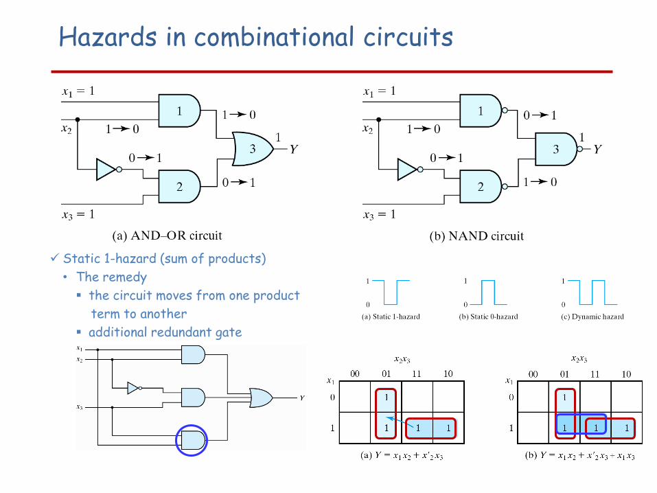
Hazards in combinational circuits
Static 1-hazard (sum of products)
• The remedy
the circuit moves from one product
term to another
additional redundant gate

Hazards in sequential circuits
An asynchronous example:
111 110111 010

Remove Hazards with Latches The implementation of the asynchronous circuits with SR latches can
remove static hazards
SR Latch (NOR type)
• Allow 1-hazard (a momentary 0 has no effect)
• The network realizing S and R must be free of 0-hazards.
S’R’ Latch (NAND type)
• Allow 0-hazard (a momentary 1 has no effect)
• The network realizing S and R must be free of 1-hazards.
Note that a sum-of-products implementation is automatically free of static 0-hazards and a product-of-sums implementation is free of static 1-hazards.

Hazard-Free Realization
S-R Latch (NOR type):
S-R Flip-Flop Driven by Equivalent Network Structure
2-level AND-OR Networks (in general faster)

Essential HazardsBesides static and dynamic hazards, another type of hazard
in asynchronous circuits is called: Essential Hazard
It is caused by unequal delays along two or more paths that originate from the same input
Cannot be corrected by adding redundant gates
Can only be corrected by adjusting the amount of delay in the affected path• Each feedback path should be examined carefully !!

Design Example
Recommended Design Procedure:
1. State the design specifications.
2. Derive a Primitive Flow Table.
3. Reduce the Flow Table by merging rows.
4. Make a race‐free binary state assignment.
5. Obtain the transition table and output map.
6. Obtain the logic diagram using SR latches.

Design Example
1) Design Specifications:
The objective is to design a negative‐edge‐triggered T flip‐flop. The circuit has two inputs T (toggle) and C (clock) and one output Q. The output state is complemented if T=1 and the clock changes from 1 to 0 (negative‐edge‐triggering). Otherwise, under all input condition, the output remains unchanged.• A Negative-Edge-Triggered T FF
• Two inputs : T, C
• Flip-Flop changes state when T = 1 and C changes from 1 to 0
• Q remains constant under all other conditions
• T and C do not change simultaneously

Design Example
2) Primitive Flow Table
e d a b g h g b c d
T
C
Q
e f a f a b c h c d e f

Design Example3) Merging of the Flow Table
Implication Table Merger Diagram
Compatible pairs: The maximal compatibles pairs are:
U=4

Maximal Incompatibles
a
c
bh
g
f
e
d
L=4

Design Example
In this particular example, the minimal collection of compatibles is also the maximal compatibles set that satisfyalso the closed condition:
(a, f) (b, g, h) (c, h) (d, e, f)

Design Example
4) State Assignment and Transition Table
No diagonal lines in the transition diagram: No need to add extra states (race-free binary state assignment!)

Design Example
5) Logic Diagram