reduction of harmonic distortion in off-grid renewable energy...
TRANSCRIPT

Reduction of Harmonic Distortion in Off-Grid Renewable Energy Systems
Ahmed Habib Jacob Lamb
Zach Ulibarri

2
Table of Contents 1. Executive Summary .................................................................................................................... 3
2. Problem Definition...................................................................................................................... 4
3. Research Survey.......................................................................................................................... 6
4. Requirements and Specifications .............................................................................................. 10
4.1 Mechanical .......................................................................................................................... 10
4.2 Electrical ............................................................................................................................. 10
4.3 Environment ........................................................................................................................ 11
4.4 Documentation .................................................................................................................... 11
4.5 Miscellaneous ...................................................................................................................... 11
4.6 Testing ................................................................................................................................. 11
5. Design ....................................................................................................................................... 12
5.1 Design Descriptions ............................................................................................................ 12
5.1.1 Inductive Reduction ..................................................................................................... 12
5.1.2 Passive Filtering ........................................................................................................... 12
5.1.3 Active Filtering ............................................................................................................ 12
5.1.4 Unified Power Quality Controller ................................................................................ 13
5.2 Design Constraints .............................................................................................................. 13
5.2.1 Cost............................................................................................................................... 13
5.2.2 Health/Safety ................................................................................................................ 13
5.2.3 Manufacturability ......................................................................................................... 14
5.2.4 Social ............................................................................................................................ 14
5.3 Design Selection ................................................................................................................. 15
6. Budget ....................................................................................................................................... 17
7. Schedule .................................................................................................................................... 18
8. Deliverables .............................................................................................................................. 20
9. Appendix A: UPQC Example Schematic ................................................................................. 21
11. Acceptance Document ............................................................................................................ 22

3
1. Executive Summary The Pure Wave team's primary project focus is to reduce the level of total harmonic
distortion (THD) which is common in the power systems of off-grid homes. THD is used to quantify the amount by which voltage and current signals are distorted. Many modern household loads (particularly those which utilize pulse width modulation for energy conservation) are non-linear and therefore create harmonics on the voltage and current waveforms when they draw power. Since these distorted waveforms can cause damage to electrical devices, and in many cases drastically shorten their lifespans, the Pure Wave team will be creating a device which reduces the voltage and current harmonics injected by a non-linear load. By analyzing frequency spectrum data on common household appliances the team found that many, but not all, household appliances produce a third harmonic which has a greater magnitude than any other harmonic produced. Thus, to reduce the THD found in an off-grid residence, the Pure Wave team will use filtering techniques designed to attenuate the third harmonic injected by non-linear loads.
The team considered several different filtering methods before deciding to use active
filtering techniques to reduce the distortion injected by household appliances. When compared with other filtering methods, active filtering is less expensive while still being extremely effective and an active filtering device would be relatively small and easy to manufacture. Furthermore, if the active filters are created for individual appliances they can be used for power factor correction as well as harmonic reduction.
During the Spring 2013 semester the team will produce a device designed to reduce
THD, a final report describing the device specifications, and a technical report on the methods used to test the effect of capacitors and super capacitors on battery systems transients in off-grid systems. Furthermore a project webpage will be created and a presentation will be given at the NAU Undergraduate Research and Design Symposium. The final device and report will be delivered on May 3rd, 2013, and the report on testing methods will be finished by March 15th, 2013. The NAU Undergraduate Research and Design Symposium will take place on April 26, 2013.
All funding for this project is being provided by you. A spending cap of $500 has been
established, and preliminary project estimates predict the funding required will be roughly $120, well below the limit set. Although the device designed by the team must be inexpensive, the team predicts prototype designs will be more expensive than the final product due to the cost of ordering parts individually instead of in bulk. In order to test the functionality of the device created the team has included travel expenses in the budget.

4
2. Problem Definition Off grid energy is frequently used in remote locations where it would be prohibitively expensive to connect to a conventional power grid. However, many of these systems experience problems when non-linear electrical devices that use pulse width modulation (PWM) to deliver power are connected to the system. Even when off grid systems use pure sine wave DC to AC inverters, PWM devices often create harmonic distortion in the voltage and current on the system’s power lines. This distortion is also present in grid-connected power systems, but is much less apparent, as the strength of the grid often forces the signals back to near sine wave operation.
Since many inverters produce a sinusoidal waveform which is roughly 60 Hz, the 2nd
harmonic component is 120 Hz, the 3rd harmonic component is 180 Hz, and the nth harmonic component is n*60 Hz. Ideally a power supply produces an undistorted 60 Hz pure sinusoidal voltage waveform, but several common household appliances, such as computer switched –mode power supplies and laser printers, draw power in brief pulses thereby distorting both current and voltage waveforms. Said another way, many common household loads (particularly those that use PWM) will create harmonics on the voltage and current waveforms when they draw power. Furthermore, these non-linear loads only create odd-integer harmonics. Total harmonic Distortion (THD) is used to quantify the amount by which a voltage signal is distorted. A large THD value indicates that a large portion of the voltage or current is not operating at the fundamental frequency, but rather an integer multiple of it.
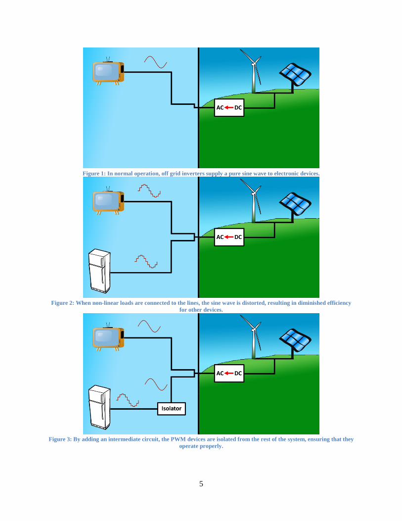
Total harmonic distortion is an important concept to consider when designing electrical systems, as a high THD can cause increased temperatures in electronics thereby shortening their lifespan. Other consequences of a high THD include lower efficiency, an increase in core temperature of electrical motors (causing damage), damage to power systems, and potential interference with telecommunication devices if the harmonics exist at the same frequency as the transmission frequency. Thus, understanding and mitigating THD levels is essential if one wants to get the most from an off grid system. To this end, the team will be creating a device which reduces the voltage and current harmonics produced by a load. The device must work reliably with all common household appliances, be easy to use, and be safe for households with pets and children. Such a device would save the user money and benefit any off grid home by reducing THD, thereby increasing the lifespan of electrical devices and increasing power quality and efficiency in the off-grid system. Figures 1, 2, and 3 show how the system will reduce THD on the power lines in the off-grid system.
5
Figure 1: In normal operation, off grid inverters supply a pure sine wave to electronic devices.
Figure 2: When non-linear loads are connected to the lines, the sine wave is distorted, resulting in diminished efficiency
for other devices.
Figure 3: By adding an intermediate circuit, the PWM devices are isolated from the rest of the system, ensuring that they
operate properly.
6
3. Research Survey Since the team's last research survey submittal on November 6, 2012, a significant
amount of time has been spent researching filtering techniques. Although there are several filtering techniques readily available, the team investigated how filtering could be done both effectively and inexpensively. The method of frequency spectrum analysis was investigated, and the specific filtering techniques researched were unified power quality conditioners, passive filters, and active filters.
Although the voltage signals generated by power sources have always had harmonic components, the magnitudes of these harmonics were generally minimal, and their effects negligible, until the use of non-linear loads became common place in the 1960s. Non-linear loads draw current from the power source in a way which is not proportional to the voltage of the supplied waveform, often times drawing energy in short bursts, or pulses, of varying width instead [1]. A common technique for drawing power in such pulses is called pulse width modulation (PWM). It is noted, however, "An unfortunate side effect of their [PWM devices] usage however, is the introduction of harmonic distortion in the power system... These harmonics flow through the power system where they can distort the supply voltage, overload electrical distribution equipment (such as transformers) and resonate with power factor correction capacitors among other issues" [2].
The tendency for devices utilizing pulse width modulation to distort the voltage waveform supplied by a power source is well known, and the issue is addressed by several sources. IEEE standard 519 suggests that a voltage signal's total harmonic distortion (THD) is less than or equal to 5% , and that the largest single harmonic is less than or equal to 3% of the fundamental voltage. IEEE provides a partial justification of these limits, stating "Higher levels of harmonics result in erratic, sometimes subtle, malfunctions of the equipment that can, in some cases, have serious consequences” [2]. Although compliance with this standard is voluntary, many efforts have been made to reduce the THD of systems. A simple observation provides an easy to implement method for controlling THD: "The key to controlling harmonic distortion is limiting the current pulses. This has been accomplished through the use of inductor coils, which may also be called reactors or chokes, on the input of the drive. The inductance of a coil creates a back electromotive force (emf), or voltage, as the current pulse passes through it. This reduces the rate of the current pulse" [3]. While the effects of this simple technique can be significant, and the improvement can be made without impacting the performance of the load, the THD of a system may still be well above those recommended by IEEE [3].
In addition to these DC link reactors, other techniques are used to reduce THD. The use of a 12 pulse transformer (12 pulse drive) design can reduce THD by approximately 90% by eliminating the 5th and 7th harmonics in the transforming windings [4]. This harmonic
7
elimination holds in theory, but can be difficult to implement practically, as this elimination requires two rectifiers sharing current exactly [5]. If exact matching is impossible or impractical, research shows “a standard six-pulse drive fed from a low pass Matrix Filter provides superior harmonic performance to a twelve-pulse drive in applications with variable loads and line voltage unbalances ranging from 0% to 3%” [5]. It may also be possible to eliminate specific harmonics using trap filters, but these filters “may cause random circuit breaker tripping and blown fuses” [4]. Alternative, situation specific THD reducing techniques also exist, but they may not provide the functionality desired for this project.
One device used for THD reduction approaches the problem by simultaneously handling several different factors which can influence the functionality of a load. The Unified Power Quality Conditioner (UPQC) is a device which uses hybrid filtering techniques to correct several power quality issues. Among its uses, we find UPQC “can be used to compensate various voltage disturbances of the power supply, to correct voltage fluctuation, and to prevent the harmonic load current from entering the power system” [6]. Thus UPQC acts as a harmonic isolator, protecting sensitive equipment from other non-linear loads. It must be noted, however, that UPQC are custom devices which utilize multiple control systems and require several transformers. Therefore, although it appears UPQC can be used to greatly reduce THD and correct a myriad of other power quality issues, the required construction is both expensive and device specific and, as such, this THD reduction method is unsuitable for this project.
A graphical THD representation provides insight into methods which can be utilized to reduce distortion on a power line. Frequency spectrum analysis is used to measure the frequency response of a signal instead of measuring the signal's time response. Using this method, a sinusoidal signal which has a theoretically infinite time response (i.e. the signal is periodic) can be represented via a finite frequency response, making analysis simpler. Since harmonic frequencies are odd integer multiples of the fundamental frequency, frequency spectrum analysis reveals a response which only has non-zero values at 60 Hz, 180 Hz, 300 Hz, etc. The results of frequency spectrum analyses for various household appliances show a characteristic common to many, though not all, residential non-linear loads: the third harmonic, 180 Hz, is the harmonic frequency with the largest magnitude, and therefore contributes most significantly to THD [7,8]. Thus if the contribution of the third harmonic can be minimized, the THD of the system will be greatly reduced. A sample frequency spectrum plot of a 4-bulb CFL lamp connected to a pure-sine wave inverter in an off-grid home is shown in Figure 4. From this figure it is clear that the largest amplitude occurs at the fundamental frequency, 60 Hz. The other frequencies all contribute to harmonic distortion, with the largest component of this distortion coming from the third harmonic, 180 Hz.

8
Figure 4: Frequency Spectrum Plot for 4 Bulb CFL Lamp [8]
Passive filters are the most basic way to remove unwanted frequencies from a signal. Passive filters use inductors, capacitors, and resistors tuned to the harmonic frequencies which are to be attenuated. In addition to removing harmonic frequencies, “well designed passive filters can be configured to provide power factor correction, reactive power compensation, or voltage support, […] and reduce the starting impact and associated voltage drops due to large loads” [6]. Furthermore, passive filters are relatively inexpensive and can be easily designed to pass specific frequencies and block others. However, passive filters have several limitations including their large size, variation in performance due to aging, and once a passive filter is installed the performance cannot be easily altered. These limitations led to alternative filters, such as active filter systems, to be sought [6,7,9]. When a filter uses an active component, such as an amplifier, it is called an active filter. Active filters can be specifically designed to remove unwanted harmonics. To do so, “an active harmonic filter injects harmonic current of opposite phase to the non-linear load current so that all harmonic currents are ideally cancelled and only the fundamental current is left to be supplied by the power system” [9]. Using active filtering to reduce THD can be much more effective than passive filtering when waveforms are highly distorted [7]. In addition to filtering unwanted harmonics, an specific types of active power filters can be used to perform power factor correction [7,9]. Thus the performance and low cost of active filters [7] make them an effective means of reducing THD.

9
Research Bibliography [1] Associated Power Technologies, Total Harmonic Distortion and Effects in Electrical Power Systems, April 2011. [Online, Accessed October 25, 2012] http://www.aspowertechnologies.com/resources/pdf/Total%20Harmonic%20Distortion.pdf [2] T. Hoevenaars, K. LeDoux, M. Colosino, Interpreting IEEE Std 519 and Meeting its Harmonic Limits in VFD Applications, May 2003. [Online, Accessed October 25, 2012] http://www.mirusinternational.com/downloads/Interpreting-IEEE-Std-519-and-Meeting-Harmonic-Limits-VFDs-PCIC-2003-15.pdf [3] The Danfoss Group, Harmonic Distortion of the AC Power Line, 2004. [Online, Accessed October 25, 2012] http://www.danfoss.com/NR/rdonlyres/37FCE24B-29AD-4842-8112-3C4B6DD0C183/0/HarmonicDistortionoftheACPowerLine.pdf [4] Yaskawa Electric America, Minimizing Total Harmonic Distortion Values, October 2006. [Online, Accessed October 26, 2012] http://www.yaskawa.com/site/dmdrive.nsf/7904b73e29cb909686256f5c00609d86/86256ec30069e43286256cc30069a44d/$FILE/AR.HARMONICS.01.pdf [5] K. Hink, Harmonic Mitigation of 12-Pulse Drives with Unbalanced Input Line Voltages. [Online, Accessed October 26, 2012] http://www.mtecorp.com/12pulse.pdf [6] E. Fuchs, M. Masoum, Power Quality in Power Systems and Electrical Machines, Burlington, Ma: Elsevier Academic Press, 2008, pp. 443- 448. [7] A. Mohammed, Analysis and Simulation of Shunt Active Power Filter for Harmonic Cancellation of Non Linear Loads, Eng. & Tech. Journal, Vol.28, No.16, 2010. [8] A. Gautam, A. Kipple, An Investigation of Off-Grid Power Quality Problems, Impacts and Possible Solutions, submitted for publication. [9] The Danfoss Group, Active Filtering is Superior [Online, Accessed November 17, 2012]. http://www.danfoss.com/NR/rdonlyres/130B566D-9CD6-4044-BDB2-707249F60828/0/Activefilteringissuperior.pdf.
10
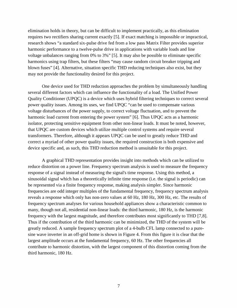
4. Requirements and Specifications Following is a set of requirements and specifications for the project that ensure it will meet the needs of the client, Dr. Allison Kipple. Specifications listed as “ideal” are the performance goals for the team, but may not be feasible. For this reason, “acceptable” specifications are given. These specifications must be met if not exceeded. These specifications have not been altered since the original project description was submitted. 4.1 Mechanical The device created by the team must be able to plug into a standard North American AC outlet. It must also have a standard North American input. The actual circuit must be contained in a 'small' box, and this box will have mounting brackets attached to help provide a user with more placement options. Since this product is designed for household use, it must be child proof and pet proof. That is, the device should be safe and tamper proof. The specifications for weight and size of the product can be found in Table 1.
Table 1: Table of mechanical specifications.
Size Weight Outlets (Output) Outlets (Input) Ideal 5''x5''x5'' 5 lbs 4 1 Acceptable 1'x1'x1' 20 lbs 1 1
4.2 Electrical Any appliance which can be plugged into a standard North American wall outlet must operate as expected when the device is being used to reduce the appliance's THD, and as such, a wide range of currents must be able to pass through the device. The THD reducing effect of the device must consistently reduce the THD of any appliance attached by at least 25%. In order to protect against current surges, the device will feature a simple fuse as they are less expensive than circuit breakers. A table of additional electrical specifications can be found in Table 2.
Table 2: Table of electrical specifications.
Voltage Range Current Range Lifespan THD Reduction Ideal 110-130 V RMS >30 A 10 Years 25% Acceptable 115-125 V RMS >20 A 5 Years 15%
11
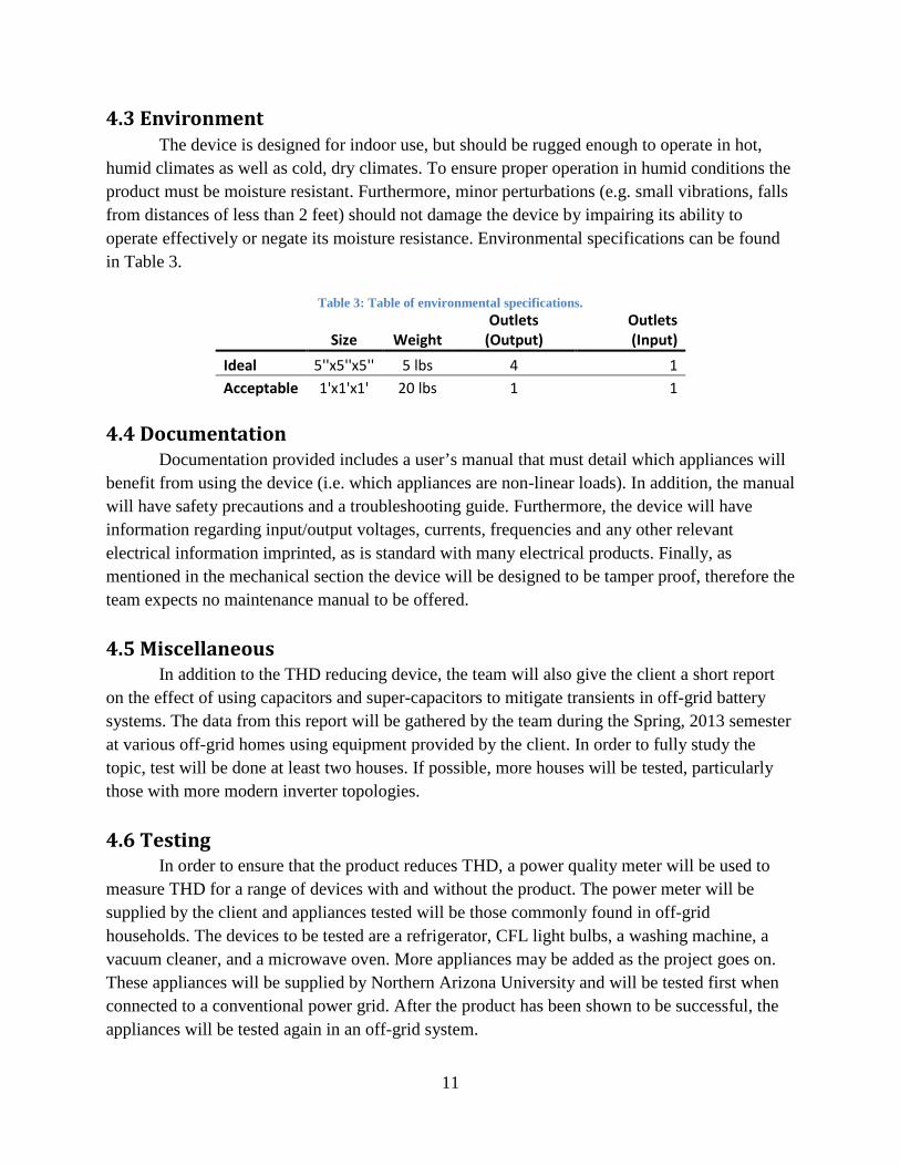
4.3 Environment The device is designed for indoor use, but should be rugged enough to operate in hot, humid climates as well as cold, dry climates. To ensure proper operation in humid conditions the product must be moisture resistant. Furthermore, minor perturbations (e.g. small vibrations, falls from distances of less than 2 feet) should not damage the device by impairing its ability to operate effectively or negate its moisture resistance. Environmental specifications can be found in Table 3.
Table 3: Table of environmental specifications.
Size Weight Outlets
(Output) Outlets (Input)
Ideal 5''x5''x5'' 5 lbs 4 1 Acceptable 1'x1'x1' 20 lbs 1 1
4.4 Documentation Documentation provided includes a user’s manual that must detail which appliances will benefit from using the device (i.e. which appliances are non-linear loads). In addition, the manual will have safety precautions and a troubleshooting guide. Furthermore, the device will have information regarding input/output voltages, currents, frequencies and any other relevant electrical information imprinted, as is standard with many electrical products. Finally, as mentioned in the mechanical section the device will be designed to be tamper proof, therefore the team expects no maintenance manual to be offered. 4.5 Miscellaneous In addition to the THD reducing device, the team will also give the client a short report on the effect of using capacitors and super-capacitors to mitigate transients in off-grid battery systems. The data from this report will be gathered by the team during the Spring, 2013 semester at various off-grid homes using equipment provided by the client. In order to fully study the topic, test will be done at least two houses. If possible, more houses will be tested, particularly those with more modern inverter topologies. 4.6 Testing In order to ensure that the product reduces THD, a power quality meter will be used to measure THD for a range of devices with and without the product. The power meter will be supplied by the client and appliances tested will be those commonly found in off-grid households. The devices to be tested are a refrigerator, CFL light bulbs, a washing machine, a vacuum cleaner, and a microwave oven. More appliances may be added as the project goes on. These appliances will be supplied by Northern Arizona University and will be tested first when connected to a conventional power grid. After the product has been shown to be successful, the appliances will be tested again in an off-grid system.
12
5. Design 5.1 Design Descriptions Several different approaches to solving the problem were considered. Brief descriptions of each of the designs are offered below.
5.1.1 Inductive Reduction Research has shown that placing an inductor in series with a non-linear load can reduce THD. This design is also effective at reducing large surge currents which can be troublesome in off-grid residences. The inductive reduction design uses a minimum of components to achieve some measure of THD reduction. The design would be much better suited to individual appliances during testing, as the component values can be easily changed as required. This would allow a large number of tests to be performed to empirically determine optimum results.
5.1.2 Passive Filtering Although the inductive reduction technique can be effective, the limited complexity of the design hampers its potential THD reduction, and thus filtering techniques were considered as a more effective alternative. A filter is a circuit that is designed to eliminate certain frequencies of electricity. Specifically, a passive filter uses resistors, inductors, and capacitors to remove undesired frequencies. The passive filter design will be to build a simple filter to eliminate the frequencies that cause the most THD. Two primary sub-designs were considered: the third harmonic filter, and the multiple harmonic filter. The third harmonic filter is designed to only attenuate the third harmonic frequency of electricity, 180 Hz. By eliminating this frequency, it is believed that THD can be reduced by a large degree without significant effects on the response of the device being filtered, as the third harmonic typically has the largest magnitude.
The multiple harmonic filter is designed to eliminate the third, fifth, and seventh harmonics. This will greatly reduce the THD in the circuit, but may cause large power loss or voltage drop.
If voltage drop is an issue, the selected design will be modified to include a
microcontroller that boosts voltage to an acceptable level.
5.1.3 Active Filtering An active filter uses operational amplifiers to remove harmonics. This can make the
device smaller or give operating characteristics that would be expensive or dangerous in a traditional passive filter (e.g. large capacitors used in passive filters can present a safety hazard even after the device is powered off). In addition, the active filter can give a gain factor greater than 1, while the passive filter necessarily drops power and voltage. As with the passive filter,

13
both third harmonic and multiple harmonic filters with optional microcontroller voltage boosters were considered.
5.1.4 Unified Power Quality Controller The Unified Power Quality Controller (UPQC) is a relatively new device typically used
in precision-machinery, such as those found in hospitals. This device uses series-active and shunt-active filters in addition to transformers to solve voltage and current harmonics. Given that a large number of components are used in the construction of such a device, this is the most complicated and expensive design considered.
The UPQC is primarily designed to provide high quality power to sensitive loads rather
than eliminate the harmonics generated by various devices. For this reason, the existing designs would be modified to better suit the intended goal of the project, which is to isolate devices that cause harmonic distortion from the rest of the power line. An example schematic of a UPQC is presented in Appendix A.
5.2 Design Constraints
5.2.1 Cost Since the final product is designed to be used in conjunction with multiple devices in the
home, the device must be made inexpensive enough that the average off-grid home owner would be able and willing to purchase one unit for each device which injects current harmonics, thereby creating harmonic distortion.
The two filtering designs would likely be very comparable in terms of cost. Although the passive filter requires large inductor and capacitor values for the high cutoffs and low frequencies used, many active filter designs require power MOSFETs, which can be expensive.
The inductive reduction design uses a minimal number of components, and so this design
would cost much less than the other THD reducing techniques.
The UPQC design is by far the most expensive of the proposed designs. This THD reduction technique relies on shunt capacitors with large values as well as several transformers and controllers, making the cost of components considerably higher than those used in any of the other designs. The cost of such a device makes it useful only for specialized applications where high quality power is needed, such as in industrial and hospital settings. As such, the cost of the UPQC makes the design unfeasible.
5.2.2 Health/Safety The device is meant to be left in a home unattended, and should therefore be safe in the
presence of children and pets. Since the inductive reduction design only uses inductors there is
14
no safety concern with this approach to reducing THD. The active filter is likewise a very safe device, as it can be easily contained in a small, tamper-proof box. The passive filter design may contain large capacitors which are potentially dangerous even after the device has been unplugged, although it too can be easily contained in a small box. The UPQC design requires the use of large capacitors as well as transformers, which have very high voltage at the terminals. If either of these components became exposed, it would present a significant danger to anyone that might touch the device. For this reason, a very large, tamper-proof container would be needed. Because of the large number of components contained within this box, heat dissipation would be a further problem.
5.2.3 Manufacturability In order to operate with the desired high cutoff response, the passive filter and inductive
reduction circuits would depend on capacitors and inductors. If the values of these components vary, the response of the filter would change. As inexpensive capacitors and inductors are only specified to within 10%, achieving high precision may be difficult when the devices enter production. By comparison, the active filter uses components which can be specified to better accuracy, making the device easier to manufacture. However, the fact that very few components are used in constructing the inductive reduction design, it maintains a slight edge in terms of manufacturability. The UPQC design will feature a large number of precision devices and will need to be custom designed. This makes it very expensive to manufacture.
5.2.4 Social One significant challenge in making the final product a success is being able to
communicate its effectiveness to the average consumer. One might think people living in off-grid homes know more about power than the average person, but this is unfortunately not the case. In order for the device to be profitable, the average user must be able to understand the benefits of using it in their daily lives. In order to effectively communicate how the device will be useful, the packaging must explain, in layman’s terms, how the device will increase the life expectancy and efficiency of every appliance being powered. The nontechnical diagram presented in the problem statement of this document will not be useful, as that explains what the device does from an electrical standpoint, rather than the benefits of the device in terms that the average person would understand. In addition to a brief summary of benefits on the device packaging, a user’s manual which provides detailed benefits of using the device must be created and included with the device.

15
5.3 Design Selection Based on the different designs that the team came up with, the third harmonic active filter
was deemed the best THD reducing method. This decision was made based on the decision matrix presented in Table 4.
Table 4: Decision Matrix for Overall Design
Design Effectiveness
(2) Cost (1)
Safety (1)
Manufacturability (.7)
Size (.5) Score
Inductive Reduction 1 10 10 10 10 34 Passive Filtering 7 9 6 7 8 37.9 Active Filtering 8 9 9 9 9 44.8
UPQC 10 1 4 1 3 27.2
Each design was rated in 5 categories. Each design was given a score of 1-10 based on its performance in that category. High scores denote better performance. Each category further has a weight associated with it, which is given in parentheses under the category. For example, cost was considered to be far more important than size, so cost is weighted at one while size is weighted at one-half. The score for each category is multiplied by the weight, and the sum of these gives the score for each design. Because the active filter design received the highest score, it was chosen as the selected design.
Effectiveness was selected as the most important category, and so it is weighted twice as
much as cost or safety. The UPQC design was given the highest score in the effectiveness category due to its ability to improve power quality in nearly any application. The two filter designs, however, are projected to be effective solutions to the problem, and thus received high scores as well. The inductive reduction method received the lowest score, as it achieves comparatively low THD reduction.
In terms of cost, the active filter and passive filters both received high scores, as detailed
in section 5.2.1. The inductive reduction design was given the highest rating, as it uses the fewest number of components.
The inductive reduction design was given the highest safety score as it only features a single inductive element. The active filter was given a high score because it has few dangerous components. It will include capacitors, but these will be of small value and present little danger to any user that may accidentally touch them. The passive design was considered to be slightly hazardous due to the potentially high-valued capacitors and inductors within it. The UPQC

16
design contains numerous dangerous components and as such, received a very poor safety rating. Further detail can be found in section 5.2.2.
Although important, manufacturability was considered to be less important than the three
previous categories because manufacturing difficulties will increase unit cost, but not to the same degree as the component cost. The inductive reduction design was once again given the highest score due to its minimal complexity. The active filter received the second highest manufacturability score because it again features a relatively small number of components, as described in section 5.2.3. The UPQC received a very low score due the large number of components and the fact that it must be designed for appliance-specific applications.
Lastly, size was given a weight of one-half because it is not as critical to the device’s
operation or marketability as the other categories. The inductive reduction design would likely be the smallest to make, so it was given the highest score. The UPQC design’s large component list makes it very large in comparison to the other designs, and thus it was given a very low score. The two filter designs were given relatively high scores, as they are not expected to take up a large amount of space. Because the active filter relies on an op-amp in lieu of passive elements, it is predicted to be slightly smaller than the passive filter design.
As the filter design had two sub-designs, third harmonic filtering and multi-level filtering,
a second design matrix was created to determine which of these methods would be most suitable for the project. This matrix is found in Table 5. The third harmonic filter was chosen as it scored higher than the multi-level filter. However, the multi-level filter design may still be implemented as a contingency if the third harmonic filter underperforms.
Table 5: Decision Matrix for Filtering Technique
Design Effectiveness
(2) Cost (1)
Safety (1)
Manufacturability (.7)
Size (.5) Score
Third Harmonic Filtering 7 10 9 8 9 43.1 Multi-Level Filtering 10 7 7 5 5 40
The third harmonic filter scored highest in cost because it will use fewer components than a multi-level filter. Because of this reduced components list, it will also be smaller and easier to manufacture. It will also be slightly safer owing to the fact that it will have less capacitors. The multi-level filter will be more effective than the third harmonic filter because it will filter out all harmonics rather than just the largest, the third harmonic. This will result in a larger reduction of THD in the system. Thus, the third harmonic filter received higher scores in all categories except effectiveness.

17
Because the third harmonic active filter design scored the highest across the two design matrices, this is the design that was chosen as the optimum solution to the problem.
6. Budget The proposed budget for the project is $122.70. This money will cover the cost of electronic components used by the team in construction of the prototype as well as travel costs. An itemized list of costs is presented in Table 6. .
Table 6: Proposed Project Budget Item Unit Cost Quantity Total Cost Power MOSFET (Model Number IRFB4620PBF) $3.77 10 $37.70 Miscellaneous Electronic Components and Packaging
$45
Travel
$40 Total Project Cost
$122.70
The final cost of the device is currently projected to be in the $20 to $30 range, but
prototyping the device will cost significantly more as spare parts are needed and the cost of individual components is higher for small orders. The bulk of the cost of constructing the prototype will be in small, inexpensive electrical components, such as resistors and small-value capacitors and inductors. These items are listed together as “miscellaneous electrical components” for brevity. The only devices that are currently being considered that cost more than a dollar per unit are the power MOSFETs, and as such, these are listed separately.
In addition, the budget includes funds for travel to various off grid homes in the northern
Arizona region. The team will have to travel to these locations to complete the field work portion of the capacitor research as well as to test isolator designs in an off-grid environment. The total of $40 was chosen as an estimate as the team does not currently know how many trips will be made or the distance travelled in each trip.
The client will pay for all costs associated with the project. The team will submit
itemized lists of components to the client along with potential suppliers. The client will then order the components and make them available to the team. Travel costs will be reimbursed to the team by the client upon submission of receipts of fuel bills. The client will also supply the team with a power quality meter for testing purposes when the first prototype device is completed.
Northern Arizona University will supply computers and software for the team to perform
designs and simulations, as well as various electrical devices to be tested.

18
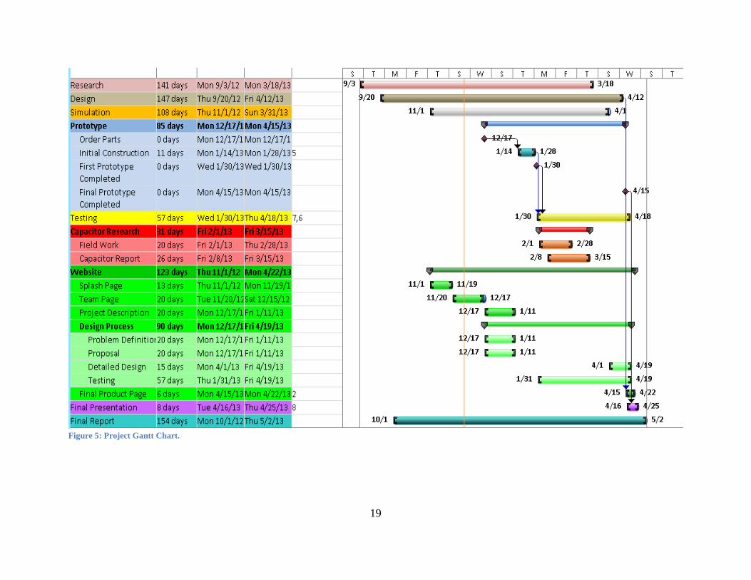
7. Schedule At the time of the writing of this document, the team had completed its initial research to see how other groups have attempted to solve the problem in the past, as well as what level of success each group achieved. It has been noted that active filtering has been used with some success in larger scale applications, and UPQC systems have been very successful in sensitive systems, albeit at a large cost. The team will continue to research possible solutions to the problems, and will give the client the preliminary parts list over NAU’s winter break. The client will order the parts so that the team will be able to begin construction as soon as the spring semester begins. Ahmed Habib will be in charge of the technical design aspects and will, with the help of the other two members of the team, continue to update the designs as new information becomes available and testing begins to offer feedback on the designs. Jacob Lamb will be in charge of documenting the process and maintaining the website. He will add new information to the website and ensure that all the data received from testing the prototypes is correct and maintained. Zach Ulibarri will be in charge of writing the report and will be the primary point of contact with the technical advisors and the client. While Jacob and Zach will serve as the primary authors for the final report and any additional documents that will be written over the course of the project, Zach will serve as the primary editor and will compile all individual contributions. All three members will contribute to the field work related to the capacitor research. The report will be primarily authored by Jacob. A Gantt Chart of the proposed project schedule can be found in Figure 5.
19
Figure 5: Project Gantt Chart.

20
8. Deliverables Several items will be given to the client as deliverables. The final project report will detail the final design and the specifications of the device that is created. This will include a fair amount of scientific data that explains how the device works as well as how effective it is in terms of the THD reduction across the tested devices. This report will be emailed to the client on May 3rd, 2012. The other primary deliverable is the prototype isolator itself. This device will be the test bench used to determine if THD reduction met the required specifications. The prototype will ideally be made to the same specifications as the final product is intended, but may merely be a proof of concept prototype. This prototype will be given to the client on May 3rd, 2012. In addition to these two primary deliverables, the team will present the client with a short technical report on the methods used to test the effect of capacitors and super-capacitors on battery transients in off-grid systems. This report will be presented to the client on the 15th of March. The team will also create a website that showcases the design process as well as the results of the isolator. This website will be stored on NAU’s servers and will offer basic and technical information on the isolator. This website will be completed by April 26th, 2012.
Lastly, the team will prepare a design presentation that will be given at the NAU Undergraduate Research and Design Symposium on April 26th, 2012. This presentation will give an overview of the system and the results of the isolator.

21
9. Appendix A: UPQC Example Schematic
This schematic was printed in Power Quality in Power Systems and Electrical Machines by E. F. Fuchs and M. A. S. Masoum. Page 447.

22
11. Acceptance Document If all terms and conditions presented in this proposal are acceptable, please sign and
return this document before December 14, 2012. By signing the document below, the signer is agreeing to all responsibilities, specifications, and deadlines presented in the proposal. If any changes to this document are required prior to signing, please contact the Pure Wave team leader, Zach Ulibarri, by emailing [email protected].
Proposal Alterations
After this document has been signed the Pure Wave team is under no obligation to accept any project changes, and, once this proposal has been accepted, any changes to the responsibilities or duties to be performed by the team must be approved by both parties.
Product Ownership Upon completion of this project, any device or designs created by the Pure Wave team in an effort to resolve the problem presented will become the intellectual property of Dr. Allison Kipple. Cessation of Duties
Pure Wave team members are no longer obligated to continue work on the project described in this proposal once the proposed project end date, May 3, 2012, has been reached. Any duties performed by team members after this date are voluntary and ownership stipulations described in this document may no longer apply. Team Signatures __________________________________________________________ Name Date __________________________________________________________ Name Date __________________________________________________________ Name Date Sponsor Signature __________________________________________________________ Name Date