reduction of blade-vortex interaction (bvi) noise … of blade-vortex interaction (bvi) noise...
TRANSCRIPT

NASA Technical Memorandum 110371
f
/_t¢?
Reduction of Blade-VortexInteraction (BVI) Noise throughX-Force Control
Fredric H. Schmitz
September 1995
National Aeronautics and
Space Administration
(NASA-TM-II0371) REOUCTION OF
_LAOE-VORTEX INTERACTION (BVI)
NOISE THROUGH X-FORCE CONTROL
(NASA. Ames Research Center) 29 P
G3/O5
N96-19055
Uncl as
0100697
https://ntrs.nasa.gov/search.jsp?R=19960013905 2018-06-02T02:31:16+00:00Z
NASA Technical Memorandum 110371
Reduction of Blade-VortexInteraction (BVI) Noise throughX--Force Control
Fredric H. Schmitz, Ames Research Center, Moffett Field, California
September 1995
National Aeronautics andSpace Administration
Ames Research CenterMoffett Field, California 94035-1000

Nomenclature
Cd
Df
f
g
H
kl
m
P
R
T
V
V
= average drag coefficient of the rotor
= drag of the helicopter's fuselage and
appendages, lb
= equivalent flat plate drag area, ft 2
= equivalent flat plate drag area of an
aerodynamically generated X-force, ft 2
= constant X-force, lb
= gravitational acceleration, ft/s 2
= H-force of the rotor, lb
= constant introduced to localize the induced
velocity
= mass of the helicopter, slugs
= point on the disk where strong BVI occurs
= rotor radius, ft
= thrust of the helicopter, Ib
= rotor induced velocity, ft/s
= non-dimensional induced velocity, v/Vr
V
Vr
VT
V
dV
dt
W
(gTPP
7
d7
dt
A7
_'TPP
_t
(3
= velocity or airspeed, knots (or ft/s)
= momentum theory hover induced velocity,ft/s
= rotor tip speed, ft/s
= non-dimensional velocity, V/Vr
= acceleration parallel to the flight path, ft/s 2
= gross weight of the helicopter, lb
= tip-path-plane angle, deg
= flight path angle, deg
= acceleration perpendicular to the flight path,
rad/s
= equivalent change in flight path angle, deg
= rotor tip-path-plane inflow, ft/s
= non-dimensional inflow, X/Vr
= advance ratio, V/Vr
= rotor solidity
Ill


Reduction of Blade-Vortex Interaction (BVI) Noise through X-Force Control
FREDRIC H. SCHMITZ
Ames Research Center
Summary
Momentum theory and the longitudinal force balance
equations of a single rotor helicopter are used to develop
simple expressions to describe tip-path-plane tilt anduniform inflow to the rotor. The uniform inflow is
adjusted to represent the inflow at certain azimuthallocations where strong Blade-Vortex Interaction (BVI) is
likely to occur. This theoretical model is then used to
describe the flight conditions where BVI is likely to occur
and to explore those flight variables that can be used tominimize BVI noise radiation. A new X-force control is
introduced to help minimize BVI noise. Several methods
of generating the X-force are presented that can be usedto alter the inflow to the rotor and thus increase the likeli-
hood of avoiding BVI during approaches to a landing.
Introduction
Rotorcrafl Blade-Vortex-Interaction (BVI) noise has been
studied extensively over the past twenty years (refs. 1-6).
Many experimental programs have been performed to
help isolate the important governing parameters of theBVI noise. Mathematical models of all levels of sophis-
tication from simple heuristic arguments to detailed
Computational Fluid Dynamics (CFD) simulations have
been developed and used to estimate the noise radiation in
the hope that the improved understanding derived fromthese models can then be used to help mitigate the
external noise radiation problem. Some success has beenachieved--but BVI still remains one of the most difficult
problems of the rotorcraft Industry.
This paper addresses the physics of the BVI problem on
very simple terms and relates these physics to the task of
using flight path control to minimize BVI noise. Decel-eration and acceleration are shown to have powerful
effects on potential BVI noise radiation. In addition, an
auxiliary control ca!led "X-force" is introduced that can
be employed to avoid rotorcraft approach conditionswhere BVI occurs. Finally, some simple methods of
generating X-force are discussed for several types ofrotorcrafl.
Necessary Conditions for BVI Impulsive
Noise
For a helicopter in forward flight, it is well known that
BVI noise occurs when the tip vortices shed from rotor
blades near the front of the rotor disk pass in close
proximity to the same or different rotor blades at latertimes near the rear and sides of the rotor disk. This is
depicted in figures 1 and 2 from the top and side views
respectively for a two bladed helicopter at an advance
ratio of about 0.17 (from ref. 7).
The view from above the rotor, in a reference frame that
moves with the rotor hub at the same velocity, shows the
geometrical complexity of the problem (fig. l). Tip
vortices shed at azimuthal positions from approximately
90 to 270 degrees are swept rearward by the forward
translational velocity, V, of the rotor where they appear
to be intersected by the same or the opposite rotor at
azimuthal positions from 270 to 90 degrees. The shed
vortices and the bound vorticity of each blade also
influence the exact position of the tip vortex filaments
with respect to the following blade in this planar view.
These apparent intersections are labeled 1 through 7 for
this particular helicopter. The sketch at an instant in timeof these vortex patterns was calculated from a classical
"free wake" computation and shows the general nature of
BVI pattern. It is known from many experimental studies
that BVI occurs on both the advancing and retreating
sides of the rotor. It is also known that the intensity of
BVI is a function of many factors including; the strength
and structure of the shed tip vortex that is passing in close
proximity to the blade, the distance from the vortex to the
blade at the vortex's closest point of passage to the blade,
the local geometry of the interaction, the velocity of theblade relative to the air when the interaction occurs, and
the relative trace tip-Mach number of the interaction. To
say the least, the problem is very complicated and has yet
to yield to robust and accurate mathematical predictions
or computational simulations.

180 °
II
90 °
I
1
I
I0o
Figure 1. Top planar view of two bladed rotor tip-vortex pattern.
2
V
Rotor wake .... ,'
a)
Rotor wake
V-_ _I_ ;" ",, , d :, , i
-.. ...... _----_,_ _- ..- - .- ..-..',.-..
b)
Rotor wake
" o i
..... #s m• i i
V ss- "'o •s • s
• .-. ............ - r-
s .--
• ..----
. . .... --'-..--'''1" •'"
c)
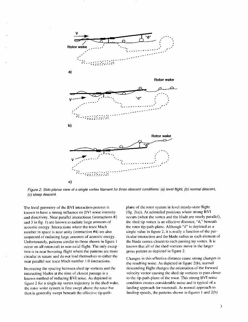
Figure 2. Side planar view of a single vortex filament for three descent conditions: (a) level flight, (b) normal descent,
(c) steep descent.
The local geometry of the BVI interaction process is
known to have a strong influence on BV1 noise intensity
and directivity. Near parallel interactions (interactions #2
and 3 in fig. 1) are known to radiate large amounts of
acoustic energy. Interactions where the trace Mach
number in space is near unity (interaction #4) are also
suspected of radiating large amounts of acoustic energy.Unfortunately, patterns similar to those shown in figure I
occur on all rotorcraft in non-axial flight. The only excep-
tion is in near hovering flight where the patterns are morecircular in nature and do not lend themselves to either the
near parallel nor trace Mach number 1.0 interactions.
Increasing the spacing between shed tip vortices and the
interacting blades at the time of closest passage is a
known method of reducing BVI noise. As depicted in
figure 2 for a single tip vortex trajectory in the shed wake,
the rotor wake system is first swept above the rotor but
then is generally swept beneath the effective tip-path-
plane of the rotor system in level steady-state flight
(fig. 2(a)). At azimuthal positions where strong BVI
occurs (when the vortex and the blade are nearly parallel),
the shed tip vortex is an effective distance, "d," beneath
the rotor tip-path-plane. Although "d" is depicted as a
single value in figure 2, it is really a function of the par-ticular interaction and the blade radius as each element of
the blade comes closest to each passing tip vortex. It is
known that all of the shed vortices move in the larger
gross pattern as depicted in figure 2.
Changes in this effective distance cause strong changes in
the resulting noise. As depicted in figure 2(b), normal
descending flight changes the orientation of the forward
velocity vector causing the shed tip vortices to pass closer
to the tip-path-plane of the rotor. This strong BVI noise
condition creates considerable noise and is typical of a
landing approach for rotorcraft. At normal approach to
landing speeds, the patterns shown in figures I and 2(b)

arctypicalforatwo-bladedrotorsystem.AdditionalbladesaddtothecomplexityoftheBVIproblembyaddingmorepotentialinteractionsforthesameadvanceratio.Eachtimeabladepassesincloseproximitytoapreviouslyshedvortex,blade-vortexinteractionnoiseisgenerated.Oneknownmethodofcontrollingthiseffectivedistanceoftheshedvorticesfromthefollowingbladesisthroughflightpathcontrol.Asdepictedinfigure2(c),furtherincreasesinrateofdescentcausethemajorityofthevorticesintheshedwaketopassabovethetip-path-planeoftherotor.Thisincreasestheeffectivedistance"d" andreducesthestrengthoftheBVInoiseradiation.Thistechniquehasbeensuccessfullyusedtohelpmitigatethenoiseonseveralhelicopters(refs.8and9).
Predictingtheprecisemissdistanceandthevortexcharacteristicsduringanencounterhasnotbeenpossiblewithtoday'stechnology.Thecomputerprogramsthathavebeendevelopedtomodeltheaerodynamics,struc-turaldynamics,andwakeofanon-axialrotorinnearproximitytothefuselagedonotcapturethenecessarydetail.Consequently,accuratenoisepredictionsarealsonotpossiblebecausetheyaredirectlyrelatedtotheimpulsiveloadingoneachbladecausedbytheseclosevortexpassages.Improvedphysicalmodelingandmoreaccuratenumericalrepresentationofthewakesystemarerequired.However,whilethesecodeshavenotalwaysperformedsatisfactorily,theycanbeusedtodiscerngeneraltrendsfortheBVIproblem.Firstthecodesmustbeadjustedtomatchexperimentaldatabychoosingkeycontrolfactors(i.e.,vortexcoresize,etc.).Thecodesarethenexercisedtopredicttrends.Aslongasthedesignsstay,reasonablyclosetothefitteddata-base,theresultsnormallyyieldconsistenttrends.A moresimple,first-orderapproach,whichisdescribedbelow,isusedin thispapertomapouttheregionswhereBVIislikelytohappen.It ishypothesizedthatthissimpleapproachisaccurateenoughtodiscerngrosscontroland/orflightpathstrategiestoavoidthelikelihoodofBVInoise.
Firstit isassumedthatBVInoiseisdirectlyrelatedtoanaveragerepresentativemissdistance"d" forthemostintenseBVIencounters.Theseoccurontheadvancingsideoftherotordiskwhenthebladeisnearlyparalleltotheshedvortex(a"broadside"encounter)orwhenthetimeoftravelfromBVIencounterpositionsalongthebladetoanobserverlocationisnearlyconstant.Thelarger"d's"depictedin figure2causeweakerBVIencountersandhencelessnoisewhilea"d"ofnearzero(head-oncollision)causeslargevaluesofBVInoiseradiation.Theaveragemissdistancecanbecalculatedby
usingsimplemomentumtheoryandthebalanceofforceequationsfors'teady-statelevelflighttofirstestimatetheaverageinflowthroughtherotordiskatchosenaggregateBVIazimuthalpositions.Theinflowcanthenbeinte-gratedtoyieldtheaveragerepresentativemissdistance,"d."Inpractice,thislaststepisavoidedandBVIisdirectlyrelatedtothenetaverageinflowthroughtherotordisk.Littleornoinflowthroughtherotorplaneispostu-latedtocausehighlevelsofBVInoisewhilelargepositiveornegativeinflowcausesweakornegligibleBVInoise.
Simplicityisthemajoradvantageofusingthisapproach.Ityieldsgoodphysicalinsightintothedominant(first-order)controlandflighttrajectoryparametersthatgovernBVInoiseandcaneasilybecorrelatedwithexistingflightdata.However,this approach is not a precise calculation
and as such can not be used to discern quantitative
changes in noise levels or for blade design. It also does
not address the question of how the pilot flies the heli-
copter using real "pilot" controls to achieve the BVI noisereductions.
Tip-Path-Plane Angle and the Longitudinal
Trim Equations
The longitudinal torce balance equations for a typical
single rotor helicopter depicted in figure 3 are shown
below. The equations are written using a "wind axis
system" which is typical in aircraft perlormance calcu-
lations. The wind axis system is chosen here for rotorcraft
performance because it lends itself to simple physical
interpretations. It should be noted that the wind axis
system becomes ill defined (singular) in hovering flight--
a performance state that is not considered in this paper.
X-Force Equation
dV
T sin(-otTpp) = Df + W sin y + H cos(-_Tpp) + m-_t (I)
Z-Force Equation
T COS(-0_Tp p ) = W COSy - H sin(-_Tp p)+ mV _t
where
H = 3 PCYrtR21"tV2_d'd ( °rH =--83P_rtR2VVT_d)
Df =/pV2f2
(2)

(_TPP
(shown
negative)
I I _ i I
TRotor tip-path-plane
• Im
!
°'".....: :o:.- ri on
W
Figure 3. Longitudinal force balance (climbing flight).
For simplicity and ease of interpretation, assume that
_TPP and 7 are small, then
sin o_Tp P = _TPP sin 7 = 7
cos _TPP =" 1.0 cos ]' = 1.0
It is also known that the "H force" as resolved in the tip-
path-plane is quite small at landing and takeoff airspeeds.
For simplicity, it will also be neglected, i.e.,
H=0
Equations 1 and 2 now become, to first-order
X-Force Equation
dV-TCXTp P = Df + W 7 + m-- (3)
dt
Z-Force Equation
T = W + mV dy (4)dt
The term mV -_t represents the apparent force that
occurs during "pull-ups" or "push-overs." During a flare
prior to landing, it effectively requires the thrust to
increase--to help arrest the helicopter's sink rate. During
an approach to a landing the pilot normally tries to
minimize large variations in flight path angle. Because
small variations in d_._y.yat landing approach speeds causedt
only small changes in thrust, changes in d7 will bedt
neglected in this analysis.
Equation 4 now simply becomes T = W and can be
substituted into equation 3, yielding:
X-Force Equation
aTPp=-Df-7 1 dV (5)W g dt
The tip-path-plane angle is simply governed by three
terms: Dr, the fuselage drag (which also includes hub
dVand interference drag); 7, the climb angle; and --, the
dt
acceleration parallel to the flight path.
Fuselage drag causes the tip-path-plane to become
negative in trimmed flight. For an AH-IG helicopter with
a 14 square foot equivalent drag area (1) at a nominal
gross weight of 10,600 lb, the variation of Df /W with
velocity is shown in figure 4 by the curve labeled 7 = 0.
It can be seen that the tip-path-plane angle becomes more
negative with increasing airspeed. The helicopter's main
rotor must tilt forward to balance the drag in steady-state
level flight.

Two scales are used in figure 4 to describe the heli-
copter's forward velocity. The non-dimensional scale
depicted by V is defined to be the actual velocity, "V,"divided by the momentum theory induced velocity in
hover, V r, where V r = _J2-2-_A' For the AH- IG
helicopter, Vr = 38.9 ft/s.
The effect of constant climb or descent angles is also
illustrated in figure 4. Positive climb angles further
decrease the tip-path-plane angle, while descents
(negative y) cause the tip-path-plane angle to become
more positive. In non-accelerating flight, the climb angle
can be chosen to maintain zero-tip-path plane angle (i.e.,
y=-Df/W).
Equation 5 also determines the effect of acceleration on
the helicopter's tip-path-plane angle. Acceleration causes
a decrease in o_TpP while deceleration causes an increase
in _TPP, an effect quite similar to the changes in climb
angle. In fact, one could think of the effect of acceleration
as a change in equivalent climb angle, i.e.,
1 dV
'SYEquivalent = g d-'_ (6)
Thus, a 0. l g acceleration parallel to the flight path is
equal to a change of 5.7 degrees of equivalent flight path
angle and hence a change in tip-path-plane angle. Accel-
eration or deceleration parallel to the flight path has a
strong influence on the helicopter's tip-path-plane angle(ref. 10).
10
Descent
angles
5
_, L = _ _. _ _."Jl_ r'_.
Climb ..,
angles
-10 I I I I I I =0 1 2 3 4 5 6
I I I I I I I i11,._
23 46 69 92 115 138
V, knots
Figure 4. Tip-path-plane angle versus forward velocity for several climb and descent angles.
6

Some additional simplifying assumptions have been
implicitly made in this balance of longitudinal force
analysis that yields the explicit expression (eq. 5) for tip-
path-plane angle. It has been assumed that the longi-
tudinal pitching moment equation is satisfied and that the
pitching moment controls employed (longitudinal cyclic,
elevator angle, etc.) do not influence the balance of forces
to first order. It has also been assumed that the engine
supplies enough power to meet the required performance
states. No real "pilot" controls have been introduced
(collective, cyclic, etc.). Instead, it has been assumed that
additional equations can be introduced along with their
associated "pilot" controls that would determine the "pilot
control" positions for each performance state.
This view of the rotorcraft performance problem is the
classical one. The performance state of the rotocraft is
determined by "X" and "Z" force balance equations. How
to fly the aircraft to achieve this performance is deter-
mined after the outer loop performance is determined. In
practice, some coupling of the moment and force balance
equations does occur. In many cases the coupling is
second order and can be neglected. The coupling has been
neglected here to highlight the physics of the force
balance equations.
The Effect of Flight path Control on Rotor
Inflow
As discussed previously, the inflow through the rotor disk
directly influences miss distances between the rotor
blades and the shed tip vortices. This situation is dia-gramatically shown in figure 5. Rotor inflow normal to
the tip-path-plane is defined to be
_TPP = V sin _TPP - v (7)
where
V = velocity of the rotorcrafi
v - induced velocity at any point on the rotor disk
Calculation of the inflow at any point on the rotor disk
requires an accurate determination of rotor induced
velocity. In general, the induced velocity is not uniform
but varies markedly both fore and aft and laterally across
the rotor disk. It is normally calculated using the strength
of the vortex elements and the vortex element positions
derived from a free-wake analysis and application of theBiot-Savart law.
A first order approximation to these miss distances can be
obtained by using a variation of simple momentum theory
and some knowledge of the non-uniform nature of the
rotor's induced velocity. Because of the closeness of the
rotor's wake to the tip-path-plane, it is assumed that the
induced velocity field in the wake and in the rotor's tip-
path-plane is the same. Initially, the induced velocity fieldis assumed to be constant across the rotor disk to be able
to derive simple expressions relating the changes of
induced velocity with changes in tip-path-plane angle.
Then local variations in the induced velocity are
accounted for and used in an approximate integration
procedure to estimate the shortest distance of a point "p"
in the rotor's wake from the rotor's tip-path-plane. In
practice, the actual time integration is not formally carried
out. The miss distance at point "p" is proportional to the
local inflow through the rotor disk.
The classical momentum theory quartic relates the
average induced velocity to the rotor's tip-path-plane
angle and the forward velocity.
2
v4 -2Vv3 sin_Tpp +V2v 2 +(+) (8)
Because T = W, equations 7 and 8 can be non-
dimensionalized by the hover induced velocity,f_
Vr = _2_A "Remembering that U.Tp pis assumed
small, equation 7 becomes
Rotor tip-path-plane_Y V sin _ ! non-uniform
/ / TPP I _ induced velocity
/'_fl/_ V _ profile
(_I'PP _ \ __.__ \ Horizon
(shown negative) _ ....... _ .... _,
shed wake position
Figure 5. A two-dimensional sketch of the rotor's velocity field.

v4 -2Vv3OtTpp + V2v2 +1 = 0 (9)
where
- v VV_----- , W_---
Vr Vr
This implicit equation can be solved for v by expanding
the induced velocity in a first order Taylor series about
small changes in ocTpP.
_vv = Vo +-- AczTp P +higher order terms (10)
o3o_TpP
avThe expressions -- and Vo are nonlinear functions
o30¢TpP
of V. Because unilorm inflow and small angles are
assumed, equation 7 becomes in non-dimensional form
_TPP = VOCTpp - v (1 l)
Substituting equation I 0 into equation 11 yields
- -- _v_TPP = VOtTPp - vo o_Tp P
3_Tpp
or
1-= -- Vc_TPP (12)V 3_--yypp
The final expression for uniform inflow is explicitly
related to the rotor's tip-path-plane angle. The induced
velocity for _TPP = 0 is plotted in figure 6. Induced
velocity rapidly falls off as a function of non-dimensional
forward velocity. The term 1 V O_p is plotted in
figure 7. It represents the change in inflow with respect to
a change in the flow normal to the rotor's tip path plane
(VO_Tpp). In the limit as V _ 0 (hover), it has a value of
0.5 but asymptotically approaches unity as V increases.
Equation 12 expresses uniform non-dimensional inflow
though the rotor disk in terms of tip-path-plane angle and
forward velocity. As discussed previously, it is knownthat the induced velocity across the rotor disk is not
uniform. It is largest toward the rear of the disk and
smallest or even negative over portions of the disk's
advancing side in the second quadrant. The most intenseblade-vortex interactions are known to occur on the
advancing side of the disk in the first quadrant around
= 45 °. The separation distances between the blade and
the shed vortices at this azimuth position are directly
affected by this less than uniform induced velocity field.
To account for the non-unitormity in the induced velocity
field, the factor K1 is introduced which effectively
reduces the inflow on the advancing side of the rotor disk
where strong BVI is known to occur. In this analysis, 0.5
is nominally chosen. Equation 12 now becomes
_TPP =-kl_°+/I- klv 30_Tpp3-_ )_O_Tp p (13)
1
.8
_o .6
.4
.2
I I I I I I1 2 3 4 5 6
g
Figure 6. Non-dimensional induced velocity, v_ , versus forward velocity, V.
I I I
3 4 5
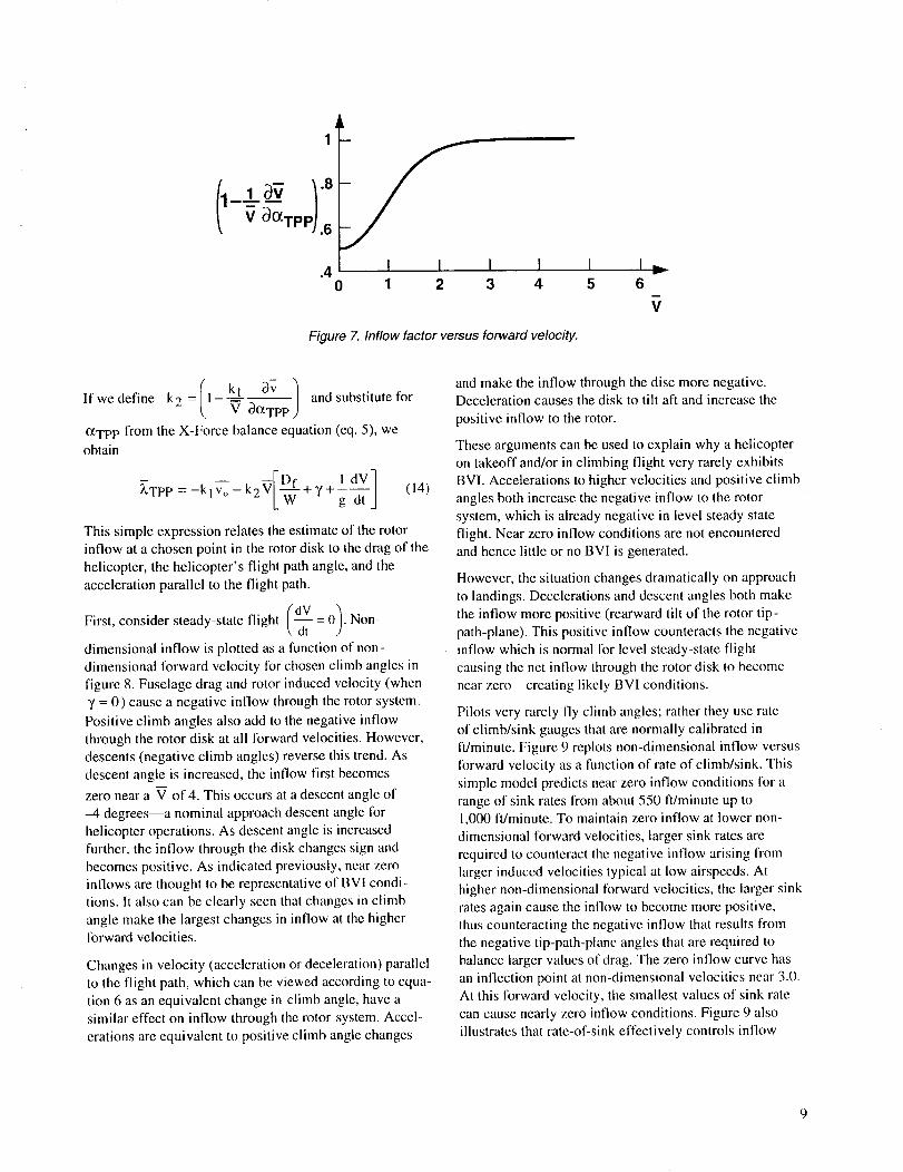
Figure 7. Inflow factor versus forward velocity.
v
6
Ifwedefine k2=/1 kl=v¢_ocTpP-c3v ) and substitute for
_TPP from the X-Force balance equation (eq. 5), we
obtain
_TPP =-kl Vo -k2V + T + g-dT ] (14)
This simple expression relates the estimate of the rotor
inflow at a chosen point in the rotor disk to the drag of the
helicopter, the helicopter's flight path angle, and the
acceleration parallel to the flight path.
First, consider steady-state flight (dV = 0/. Non-\ dt 2
dimensional inflow is plotted as a function of non-
dimensional forward velocity for chosen climb angles in
figure 8. Fuselage drag and rotor induced velocity (when
3' = 0) cause a negative inflow through the rotor system.
Positive climb angles also add to the negative inflow
through the rotor disk at all forward velocities. However,
descents (negative climb angles) reverse this trend. As
descent angle is increased, the inflow first becomes
zero near a V of 4. This occurs at a descent angle of
-4 degrees--a nominal approach descent angle lot
helicopter operations. As descent angle is increased
further, the inflow through the disk changes sign and
becomes positive. As indicated previously, near zero
inflows are thought to be representative of BVI condi-
tions. It also can be clearly seen that changes in climb
angle make the largest changes in inflow at the higherforward velocities.
Changes in velocity (acceleration or deceleration) parallelto the flight path, which can be viewed according to equa-
tion 6 as an equivalent change in climb angle, have asimilar effect on inflow through the rotor system. Accel-
erations are equivalent to positive climb angle changes
and make the inflow through the disc more negative.Deceleration causes the disk to tilt aft and increase the
positive inflow to the rotor.
These arguments can be used to explain why a helicopter
on takeoff and/or in climbing flight very rarely exhibitsBVI. Accelerations to higher velocities and positive climb
angles both increase the negative inflow to the rotor
system, which is already negative in level steady state
flight. Near zero inflow conditions are not encounteredand hence little or no BVI is generated.
However, the situation changes dramatically on approach
to landings. Decelerations and descent angles both make
the inflow more positive (rearward tilt of the rotor tip-
path-plane). This positive inflow counteracts the negative
inflow which is normal for level steady-state flight
causing the net inflow through the rotor disk to become
near zero----creating likely BVI conditions.
Pilots very rarely fly climb angles; rather they use rate
of climb/sink gauges that are normally calibrated in
ft/minute. Figure 9 replots non-dimensional inflow versus
forward velocity as a function of rate of climb/sink. This
simple model predicts near zero inflow conditions for a
range of sink rates from about 550 ft/minute up to1,000 ft/minute. To maintain zero inflow at lower non-
dimensional forward velocities, larger sink rates are
required to counteract the negative inflow arising from
larger induced velocities typical at low airspeeds. At
higher non-dimensional lbrward velocities, the larger sink
rates again cause the inflow to become more positive,thus counteracting the negative inflow that results from
the negative tip-path-plane angles that are required to
balance larger values of drag. The zero inflow curve has
an inflection point at non-dimensional velocities near 3.0.
At this forward velocity, the smallest values of sink rate
can cause nearly zero inflow conditions. Figure 9 also
illustrates that rate-of-sink effectively controls inflow
9

-1 .o I I0 1 2 3 4 5
%,%
I I I °Jr
6
138
V, knots
I I I I I I23 46 69 92 115
Figure 8. Non-dimensional Inflow at point "p" as a function of forward velocity for several flight path angles.
0.20 _\Z
-°° - •2,r__--// - R/C = 0 ft/min " \\\ ,,
-0.6 I I - _
._O8 1 1 I I I I I0 1 2 3 4 5 6
Figure 9. Non-dimensional inflow, _ versus forward velocity for several rates of climb.
over the entire forward velocity range; unlike climb/
descent angle which was only really effective at high
forward speeds.
The classical way of presenting regions where BVI noise
is likely has been on a rate-of sink versus forward
velocity plot. (refs. 8 and 9). A replotting of equation 14
in this format for a series of non-dimensional inflows is
shown in figure 10. Two scales are shown in this figure
for velocity: a dimensional scale for the AH-IG heli-
copter and the non-dimensional scale used in the general
analysis.
10

400
200
.__ -200E
E
"_ -400'3_=03CE
--800 "'_"
_ /'/
6O
--.4 •
Climb
_//i I ilfsii_,71 - . .-. iioliiii I ", iiii]i,, DescentS7
".
/I 11J ..... mw _=0 " ". _'' '"
°'_.o .1
%
%.
\I t,
80 100
qb *% • •
• _ °% %
k
•, \
"\. _ \
"M _. I
120 140
I I I I [ I
V, knots
I =.1.0 2.0 3.0 4.0 5.0 6.0
Figure 10. Rate of climb versus forward velocity for several values of non-dimensional inflow.
Inflow near zero is achieved at large sink rates at both low
and high forward airspeeds according to figure 10. How-
ever, large sink-rates at low forward airspeeds are known
to violate the assumptions of simple momentum theory.Therefore, at velocities below 40 knots at sink rates of
less than 600 ft/minute, the simple theory presented here
is invalid. This is not a serious problem for BVI noise
predictions in most cases. Approach to landings are rarely
done at airspeeds less than 40 knots. In addition, the
epicycloid-like patterns of shed tip vortices are less likely
to encounter following blades in near parallel interactions
or have trace Mach numbers near unity at these slower
airspeeds-----conditions known to be necessary to generate
strong BVI noise.
At velocities above 40 knots, the modeling predicts
near zero inflow at approximately 550 fdminute at
60-80 knots airspeeds. Above 80 knots, the sink rate to
achieve zero net inflow through the rotor disk increases,
becoming almost 1,000 ft/minute at 120 knots.
The HAl "Fly Neighborly Program" (ref. 9) uses similar
knowledge of quiet regions in rate of sink versus forward
space to help pilots minimize BVI noise. Based lbr the
most part on noise measurements in the cabin of the
helicopter, regions of loudest BVI noise levels were
mapped out as shown in figure l 1 lbr a medium weight
helicopter (ref. 9). BVI tbr this 8,000 lb class helicopter is
prevalent at about 400 ft/minute sink rate at about 60 to
80 knots--quite similar to the near zero inflow case
predicted by this simple theoretical model.
The findings that the BVI region shown in figure I l is
closed and the theoretical curves shown in figure 10 do
not yield closed regions needs some explanation. As
discussed previously, this simple theory is invalid at
airspeeds less than 40 knots at high sink rates. However,because BVI at these low airspeeds are not usually
parallel encounters or do not have trace Mach numbers
of 1, the radiated noise is not as intense as it is at higher
11

1200
1000
800
- _ Intermittent slap
- _ Continuous slapm
Loud slap
_ _ Maximum slap
40 50 90 1001 )130
Velocity, knots
Figure 11. Measured cabin noise levels as a function of rate of climb and forward velocity, "fried egg plot" (from ref. 9).
airspeeds. The measured closed boundary at low
airspeeds in figure 11 reinforces this hypothesis.
The measured BVI region in figure 11 also closes at
higher airspeeds. This simple theory does not offer an
explanation for this phenomenon either. In fact, the theory
indicates that BVI will exist at higher airspeeds at highersink rates. However, other measured full-scale acoustic
data (refs. 11 and 12), taken in the acoustic far field using
a flying microphone, support the theory. Strong BVI
pulses were measured at high sink rates at high forward
velocities. A possible explanation for these differences
may be related to the fact that higher speed BVI noise
may not always be able to be heard in the helicopter
cabin. The strong BVI regions would appear to close as
shown in figure 10, but in actuality helicopters flyingunder these conditions would still radiate BVI noise but
in directions other than towards the helicopter cabin.
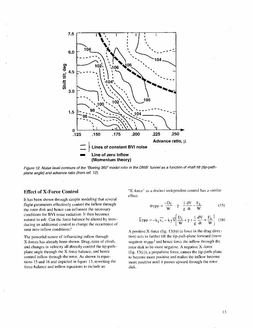
Additional acoustic data (ref. 13) from four approxi-
mately quarter scale model rotors also support the simple
theory. A portion of the acoustic data for a "Boeing 360"
model rotor test performed in the DNW wind tunnel is
shown in figure 12 on a plot of shaft angle tilt versusadvance ratio. The data were taken 25 degrees below the
plane directly in front of the model rotor. Because the test
was done using an isolated rotor in a wind tunnel, the
inflow equation (eq. 14) has to be modified to reflectthese conditions. There is no inflow due to climb,
acceleration, or helicopter drag. In the wind tunnel forzero inflow, the rotor shaft must tilt aft to balance the
negative inflow that arises from the rotor's induced
velocity. The predicted zero inflow curve for the "Boeing
360" model rotor using this theory is superimposed on the
data in figure 12. The trend of decreasing shaft tilt angle
with increasing airspeeds is well predicted by the theory.
This general trend is also confirmed in other model scale
wind tunnel test programs (refs. 14 and 15).
A closer look at figure 12 and the other acoustic data ofreferences 13-15 indicates that there are other factors
that set the level of BVI noise. Within the general trend
predicted by this momentum theory model, several small
regions of larger intensity sometimes exist. The actual
noise levels in these regions are dependent upon many
design factors of the rotor itself as well as the acoustic
phasing relationships of the BVI interactions. It alsoshould be noted that model scale BVI data taken in wind
tunnels have a tendency to under predict the measured
full scale data (ref. 16) This is a possible explanation for a
general lessening in the acoustic intensity levels with
increasing airspeed at higher airspeeds in the model scaledata of reference 12.
12
I
/ Lines of constant BVInoise
-- Line of zero inflow
(Momentum theory)
Figure 12. Noise level contours of the "Boeing 360" mode/rotor in the DNW tunnel as a function of shaft tilt (tip-path-
plane angle) and advance ratio (from ref. 12).
Effect of X-Force Control
It has been shown through simple modeling that several
flight parameters effectively control the inflow throughthe rotor disk and hence can influence the necessaryconditions for BVI noise radiation. It then becomes
natural to ask: Can the force balance be altered by intro-
ducing an additional control to change the occurrence ofnear zero inflow conditions.'?
The powerful nature of influencing inflow throughX-forces has already been shown. Drag, rates of climb,
and changes in velocity all directly control the tip-path-
plane angle through the X-force balance, and hence
control inflow through the rotor. As shown in equa-tions 15 and 16 and depicted in figure 13, rewriting the
force balance and inflow equations to include an
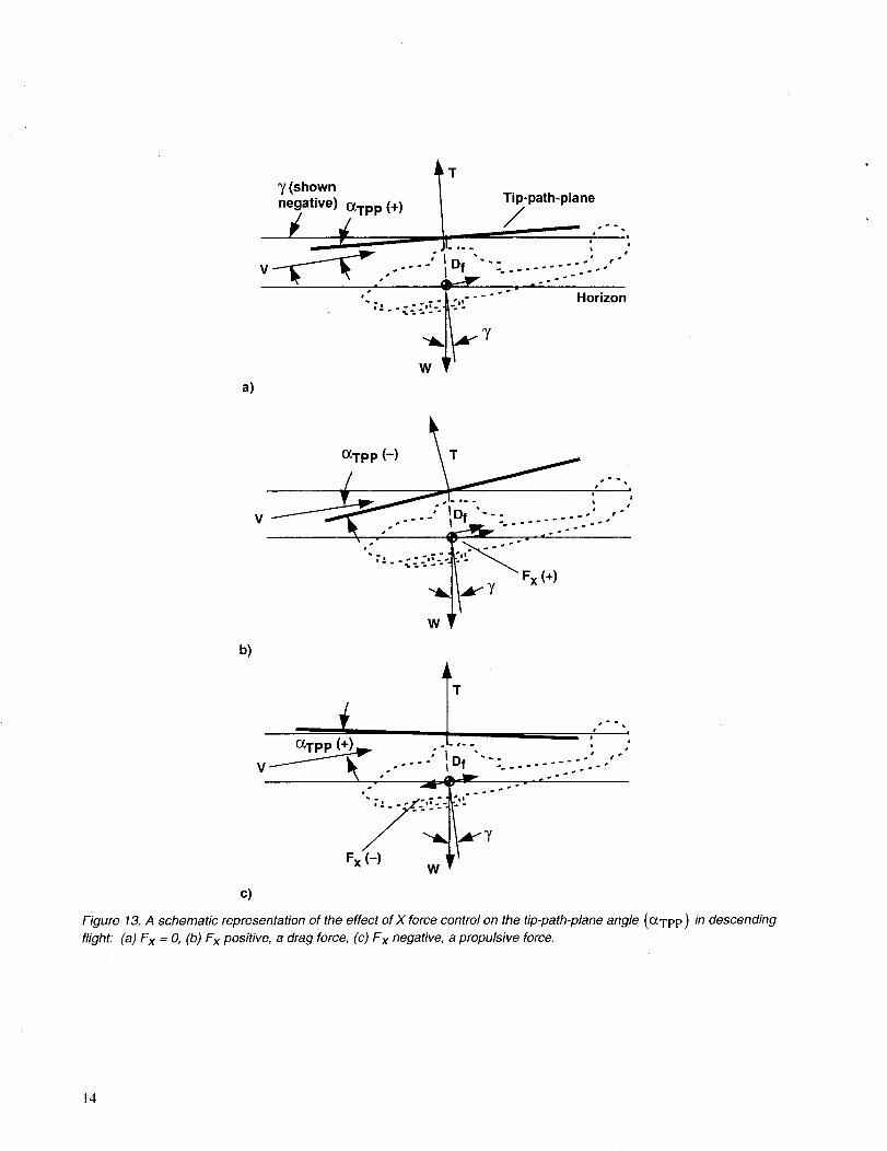
"X-force" as a distinct independent control has a similareffect.
-Dr 1 dV F xOCwpe - _, (15)
W g dt W
_Tpp =_alva_ k2V[___..+7+ 1 dV+ Fx ]7-a-TtWj (,6)
A positive X-force (fig. 13(b)) (a force in the drag direc-
tion) acts to further tilt the tip-path-plane forward (more
negative o_Tp P) and hence lorce the inflow through the
rotor disk to be more negative. A negative X-|orce
(fig. 13(c)), a propulsive force, causes the tip-path-plane
to become more positive and makes the inflow become
more positive until it passes upward through the rotordisk.
13
a)
_Ty (shownnegative) Tip-path-plane
__ OCTPP(+) / .i
V --" Df ........ " ',r"
T.,. °;.-. ° " "-- .... Horizon
Y
b)
OCTpP (-) _ T
" "-.-.;..'-'.'.'-.'°_-'_ Fx (+)
c)
TB
_.a°. l
V _ Df -.- -." . '
Fx (-)W
Figure 13. A schematic representation of the effect of X force control on the tip-path-plane angle (o_TpP) in descending
flight: (a) Fx = O, (b) Fx positive, a drag force, (c) Fx negative, a propulsive force.
14

The effect of a constant X-force which is independent of
forward airspeed on the change in inflow through therotor disk is shown by the solid curves in figure 14 tbr
two levels of positive and negative l_x. Good tip-path-W
plane control and hence inflow control is shown for
values of forward velocity above a V of 1.0. At high
values of V, X-force control becomes a powerful method
of altering inflow and hence avoiding the likelihood ofBVI noise radiation.
An X-three control that is proportional to velocity
squared (a drag control device) is also plotted in figure 14
(dashed lines) as a function of tbrward velocity. Three
levels of increased equivalent effective flat plate drag
area are shown for the AH-1G helicopter: 14, 28, and
42 square feet. The change in inflow from this X-force
drag control device is seen to be very effective at higherforward velocities but much less effective than a constant
X-force control at lower velocities.
A _ Constant X- force/
•6 _-__ . X-force~V 2Fe_ W =-.1
.4A
.2 I-- / _ Propulsive_
_0ca" _-force I
'_ _" fe 14 ft 2 Drag
-.2 __ x-f°rce
-.4_-- W_ ___') _ _ ft 2
-.6 _28
0 1 2 3 4 5 6
I I I I I I I23 46 69 92 115 138
V, knots
Figure 14. Change in inflow due to changes in X-force.
15
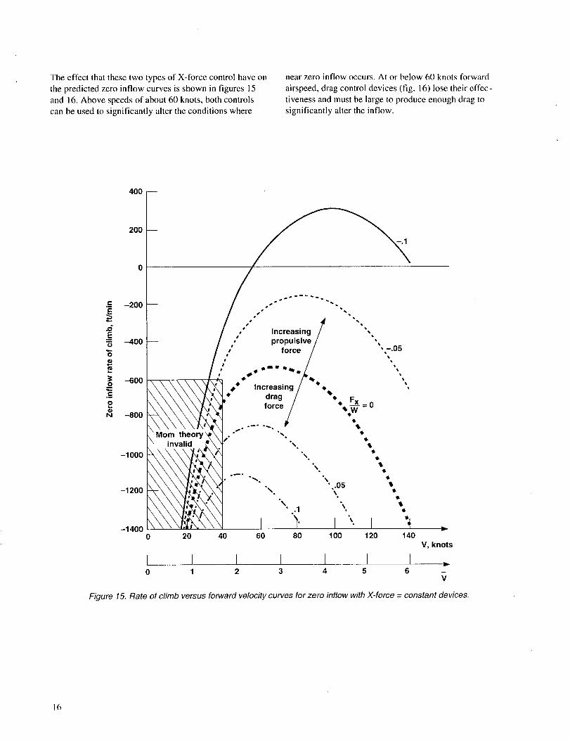
The effect that these two types of X-force control have on
the predicted zero inflow curves is shown in figures 15
and i 6. Above speeds of about 60 knots, both controls
can be used to significantly alter the conditions where
near zero inflow occurs. At or below 60 knots forward
airspeed, drag control devices (fig. 16) lose their effec-
tiveness and must be large to produce enough drag to
significantly alter the inflow.
200
-200
en
E•" -400
"6
-600Om
C.B
oQ)N --800
-1000
-1200
-1400
$
$
$
$
Mom theoryinvalid
e'" Increasing ,• propulsive/ ,,
/ force / ,--.05,,
Increasing
,t, drag /_'• F..xx
force/ *_.W• = 0
%%°
%,
0 20 40 120 140V, knots
I I I I [ I I ,.0 1 2 3 4 5 6
Figure 15. Rate of climb versus forward velocity curves for zero inflow with X-force -- constant devices.
16

.m
E
.6EO
"6
o_i
2G)N
-40O
--6OO
-80O
-1000
-1200
-1400
=
I20 40 60 80 100 120
I I I I I I0 1 2 3 4 5
140
V, knots
6
Figure 16. Rate of cfimb versus forward velocity curves for zero inflow with X-force aerodynamic drag devices
17

X-Force Controllers
A speed brake as sketched in figure 17 is one of the more
simple X-force controllers. As hypothetically shown,
panels can be mounted to the sides of the helicopter
which, when employed, generate additional drag
(X-force). In general, this class of devices will generate
an X-force that is proportional to tbrward velocity
squared and thus change the inflow according to thedashed curves in figure 14.
The effect of speed brake-like devices on the rate-of-sink
versus forward velocity plots for a series of positive and
negative inflows is shown in figure 18. An increase in the
equivalent effective flat plate drag area of twice that of
the AH-1G helicopter has been assumed to result from the
deployment of these drag devices. When these curves are
compared with the constant inflow curves of figure 10,
significant changes are apparent. At a typical landing
approach speed of 70 knots and 550 ft/minute rate-of-
0
A
T
A
Figure 17. A sketch of an X-force "brake-like" device for a single rotor helicopter.
18

sink, the AH-IG was shown likely to produce significant
amounts of BVI noise. Using the simple momentum
theory model, near zero inflow was predicted to be likely.
With the speed brake-like devices deployed, the zero
inflow curve shifts downward--requiring higher sink-
rates to produce the near zero inflow conditions. In effect,
the tip-path-plane of the rotor has been forced to tilt-further forward to maintain X-force trim which increase
the negative inflow through the rotor disk at the same sinkrate. This increased inflow decreases the likelihood of
strong BVI encounters at the 70 knots and 550 ft/minute
landing approach conditions. As shown in figure 18, at70 knots, it now takes about 850 ft/minute to generate the
near-zero inflow condition and, as a consequence, pro-
duces the likelihood of strong BVI noise. At higher
airspeeds, the effect on the flight profiles is even moredramatic.
Obtaining a pure aerodynamic X-force of significant
magnitude from drag-like devices to alter the inflow
through the rotor disk is an engineering challenge.
Another potential method of generating the required
e-
E
.6E"6"6
400
200
0
-200
--4O0
-600
--800
-1000
-1200
-1400
Climb
Descent
140
V, knots
Figure 18. Rate of sink versus forward velocity for several values of inflow--aerodynamic drag devices deployed,F x-V 2 and fe=28 ft 2.
19
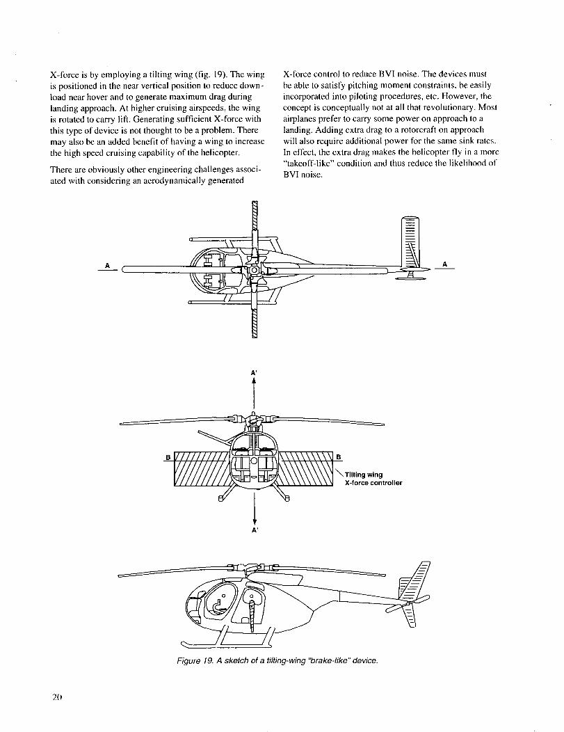
X-Jbrceisbyemployingatiltingwing(fig.19).The wing
is positioned in the near vertical position to reduce down-
load near hover and to generate maximum drag during
landing approach. At higher cruising airspeeds, the wing
is rotated to carry lift. Generating sufficient X-force with
this type of device is not thought to be a problem. There
may also be an added benefit of having a wing to increase
the high speed cruising capability of the helicopter.
There are obviously other engineering challenges associ-
ated with considering an aerodynamically generated
o
X-force control to reduce BVI noise. The devices must
be able to Satisfy pitching moment constraints, be easily
incorporated into piloting procedures, etc. However, the
concept is conceptually not at all that revolutionary. Most
airplanes prefer to carry some power on approach to a
landing. Adding extra drag to a rotorcraft on approach
will also require additional power for the same sink ratcs.
In effect, the extra drag makes the helicopter fly in a more"takeoff-like" condition and thus reduce the likelihood of
BVI noise.
r_
U
A'
T
A'
Figure 19. A sketch of a tilting-wing "brake-like" device.
20
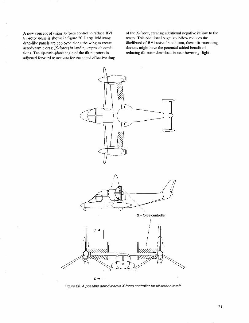
Anewconceptof using X-force control to reduce BVI
tilt-rotor noise is shown in figure 20. Large tbld away
drag-like panels are deployed along the wing to create
aerodynamic drag (X-force) in landing approach condi-
tions. The tip-path-plane angle of the tilting rotors is
adjusted forward to account for the added effective drag
of the X-force, creating additional negative inflow to the
rotors. This additional negative inflow reduces the
likelihood of BVI noise. In addition, these tilt-rotor drag
devices might have the potential added benefit of
reducing tilt-rotor download in near hovering flight.
//",\
SX - force controller
c..-J
Figure 20. A possible aoroOynamic X-forco controller for tilt-rotor aircraft.
21

A sketchofahypotheticalconstantX-forcecontrollerisshowninfigure21.Inthiscase,twoductedpropellersaremountedtoeithersideofthefuselagetoproduceaneffectiveX-force(dragorpropulsiveforce).ThepitchoftheductedrotorbladesisusedtomaintainaconstantX-forceandhencecaneffectivelycausethetip-path-plane
totiltovertheentireapproachvelocityrange-evenatlowapproachairspeeds.Theeffecttheseconstantforcecon-trollershaveontheconstantinflowcurvesisshowntorconstantdragandconstantpropulsiveforcein figures22and23respectively.
__J'__ X - force controller
Figure 21. A sketch of a possible constant X-force controller.
22
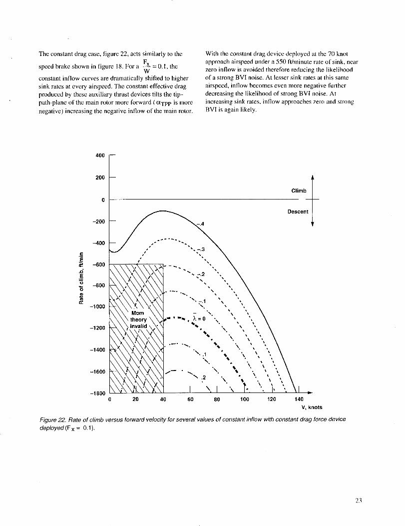
The constant drag case, figure 22, acts similarly to the
speed brake shown in figure 18. For a Fx = 0.1, theW
constant inflow curves are dramatically shifted to higher
sink rates at every airspeed. The constant effective drag
produced by these auxiliary thrust devices tilts the tip-
path-plane of the main rotor more forward ( _TPP is more
negative) increasing the negative inflow of the main rotor.
With the constant drag device deployed at the 70 knot
approach airspeed under a 550 ft/minute rate of sink, near
zero inflow is avoided theretore reducing the likelihood
of a strong BVI noise. At lesser sink rates at this same
airspeed, inflow becomes even more negative further
decreasing the likelihoo d of strong BVI noise. At
increasing sink rates, inflow approaches zero and strong
BVI is again likely.
t,,-
E
.¢1
.E0
n-
400
200
-200
-4OO
-6OO
-8O0
-1000
-1200
-1400
-1600
-1800
Climb
Descent
0 20 40 60 80 100 120 140
V, knots
Figure 22. Rate of climb versus forward velocity for several values of constant inflow with constant drag force device
deployed (F x = 0.1 ).
23

The effects of a constant propulsive force of F----Lx= -0.1W
is shown in figure 23. The thrust causes the tip-path-plane
to tilt rearward and increases the inflow through the disk
in the direction of the thrust vector. In this positive inflow
case, the shed vortices pass above the rotor's tip path
plane. The auxiliary thrust devices have now placed the
helicopter in an autogyro-like mode. At the 70 knots,
550 ft/minute rate of sink, the inflow is now positive,
thus reducing the likelihood of BVI noise. Now lower
rates of sink reverse this trend and cause near zero inflow
conditions to be approached.
r-
E
.5
.E_"5
"6
¢o
1200 _--
1000
800
600
400
200
-200
-400
-600
/
/
-8000 20 40 60 80 100 120 140
V, knots
Figure 23. Rate of climb versus forward velocity for several values of constant inflow with a constant propulsive force
device deployed (Fx = -0.1 ).
24

Some Dynamic Performance Observations
An auxiliary X-force controller to minimize BVI noise
has been shown to be an effective method of reducing the
likelihood of strong BVI noise. This simple analysis has
conceptually explored the effectiveness of a few of these
X-force producing devices using a quasi-static analysis,
where acceleration perpendicular to the flight path has
been neglected and acceleration parallel to the flight pathhas been considered as a parametric variable. In essence,
the steady-state longitudinal force equilibrium equationshave been solved.
Much of an approach to a conventional landing is per-formed in this manner. The pilot tries to maintain a con-
stant airspeed and sink-rate until he begins to approach
his landing site. At that point, the helicopter is decelerated
to reduce airspeed and is flared to arrest the rate of sink.Both of these actions tend to increase BVI. The accelera-
tion perpendicular to the flight path in a flare effectivelyincreases thrust and hence the strength of the tip vortices.
Decelerations along the flight path tilt the tip-path-plane
further aft (more positive _TPP) and increases the
positive inflow through the rotor disk. If the inflow in the
approach condition is negative without deceleration, the
positive change in inflow due to deceleration can make
the net inflow go to zero, resulting in the likelihood of
strong BVI. Fortunately, the BVI is confined to the
terminal area during deceleration and is probablytolerable.
Using a propulsive force in the "X" direction during
approach can avoid strong BVI during the flare anddeceleration. Since the inflow in this landing condition is
already positive, deceleration only tilts the tip-path-plane
further aft further increasing the positive inflow. This
moves the shed tip vortices further away from the bladesand reduces even further the likelihood of strong BVI.
Conclusions
Simple analytical modeling of the longitudinal trim
equations and rotor inflow for a single rotor helicopter
have been developed to generally describe the conditions
under which BVI is likely during approach to a landing.
The model is quasi-static, treating acceleration parallel to
the flight path as a parametric variable. This first order
modeling has shown that:
• Vehicle drag, increases in climb angle, and accel-eration all decrease the rotor's tip-path-plane angle
and thus increase the negative inflow through the
rotor.
• Increases in descent angle and deceleration increasc
the rotor's tip-path-plane angle and thus increasethe positive inflow through the rotor.
• In steady-state flight during a landing approach,
the inflow to the rotor can approach zero. During
these conditions, strong BVI is likely. The region
where this occurs can be described by a partially
bounded region in rate-of-sink versus lbrward
velocity space.
In addition, a new X-force control has been introduced
to alter the conditions under which strong BVI is likely.It has been shown that:
• The effect of both a positive and negative X-torcecontrol can be used to minimize the likelihood of
BVI noise radiation.
• Drag-like devices and constant X-force devices
have been conceptually suggested that can produce
the required X-forces. These novel concepts need
further engineering study, experimentation, andrefinement to ensure that low noise BVI conditions
can be attained without incurring too much
operational complexity or mission perlbrmance
penalties.
References
1. Cox, C. R.: Subcommittee Chairman's Report to
Membership on Aerodynamic Sources of Rotor
Noise. Reprint No. 625, 28th Annual Forum,
American Helicopter Sot., Inc., May 1972.
2. George, A. R.: Helicopter Noise: State-of-the-Art.Journal of Aircraft, vol. 15, no. 11, 1978,
pp. 707-715.
3. White, Richard P., Jr.: Thc Status of Rotor Noise
Technology. Journal of American Helicopter
Sot., vol. 25, no. I, Jan. 1980, pp. 22-29.
4. Schmitz, F. H.; and Yu, Y. H.: Helicopter Impulsive
Noise: Theoretical and Experimental Status.Journal of Sound and Vibration, vol. 109, no. 3,
Sept. 22, 1986, pp. 361-422.
5. JanakiRam, R. D.: Aeroacoustics of Rotorcraft.
AGARD Report 78 I, 1990.
6. Lowson, M. V.: Progress Towards Quieter CivilHelicopters. Aeronautical Journal, pp. 209-223,June 1992.
25

7. Tangler,JamesL.:SchlierenandNoiseStudiesofRotorsinForwardFlight.33rdAnnualNationalForum,AmericanHelicopterSociety,Inc.,May1977,pp.77.33-05-1--77.33-05-12.
8. Halwes,D.R.:FlightOperationstoMinimizeNoise.PresentedattheAmerican Helicopter Society-
AIAA-University of Texas at Arlington Joint
Symposium on Environmental Effects of VTOL
Designs, Arlington, Texas, Nov. 16-18, 1970,
and Vertiflite, Feb. 1971.
9. Helicopter Association International (HAl) Fly
Neighborly Committee. Fly Neighborly Guide,
HAl, Feb. 1992.
10. Chen, R. T. H.; Hindson, W. S.; and Mueller, A. W.:
Acoustic Flight Tests of Rotorcraft Noise-
Abatement Approaches Using Local DifferentialGPS Guidance. Presented at the American
Helicopter Society Specialists Conference on
Rotorcraft Aeromechanical Technologies,
Fairfield County, Conn., Oct. 11-13, 1995.
11. Boxwell, D. A.; and Schmitz, F. H.: Full-Scale
Measurements of Blade-Vortex Interaction
Noise. Journal of the American Helicopter
Society, vol. 27, no. 4, Oct. 1982, pp. I 1-27.
12. Boxwell, D. A.; and Schmitz, F. H.: In-flight
Acoustic Comparison of the 540 and K747 Main
Rotors for the AH-1G Helicopter. ProductionValidation Test-Government: Kaman K747
Improved Main Rotor Blade, USAAEFA Project
No. 77-38, U.S. Army, Oct. 1979, pp. 65-90.
13. Gallman, J. M.; and Liu, S. R.: Acoustic Character-
istics of Advanced Model Rotor Systems.Presented at the 47th Annual Forum of the
American Helicopter Society, 1991.
14. Shenoy, K. R.: The Role of Scale Models in the
Design of Low BVI Noise. Presented at the 41st
Annual Forum of the American Helicopter
Society, May 15-17, 1985.
15. Marcolini, M. A.; Martin, R. M.; Lorber, P. F.; and
Egolf, T. A.: Predictions of BVI Noise Patternsand Correlations with Wake Interaction Loca-
tions. Presented at the 48th Annual Forum of the
American Helicopter Society, Washington, D.C.,June 3-5, 1992.
16. Boxwell, D. A.; Schmitz, F. H.; Splettstoesser,
W. R.; and Schultz, K. J.: Helicopter Model
Rotor-Blade Vortex Interaction Impulsive Noise:
Scalability and Parametric Variations. Journal
of American Helicopter Society, vol. 32, no. I,
Jan. 1987, pp. 3-12.
26

REPORT DOCUMENTATION PAGEForm Approved
OMB No. 0704-0188
Public reportingburden for this collectionof informationis estimated to average 1 hourper response, including the time for reviewing instructions, searching existing data sources,gathering and maintaining the data needed, and completing and reviewing the collection of information. Send comments regarding this burden estimate or any other aspect of thiscollection of information, including suggestions for reducing this burden, to Washington Headquarters Services, Directorate for information Operations and Reports, 1215 JeffersonDavis Highway, Suite 1204, Arlington, VA 22202-4302, and to the Office of Management and Budget, Paperwork Reduction Project (0704-0188), Washington, DC 20503.
1. AGENCY USE ONLY (Leave blank) 2. REPORT DATE 3. REPORT TYPE AND DATES COVERED
September 1995 Technical Memorandum4. TITLE AND SUBTITLE 5. FUNDING NUMBERS
Reduction of Blade-Vortex Interaction (BVI) Noise throughX-Force Control
6. AUTHOR(S)
Fredric H. Schmitz
7. PERFORMINGORGANIZATION NAME(S)AND ADDRESS(ES)
Ames Research Center
Moffett Field, CA 94035-1000
9. SPONSORING/MONITORING AGENCY NAME(S) AND ADDRESS(ES)
National Aeronautics and Space Administration
Washington, DC 20546-0001
505-59-36
8. PERFORMING ORGANIZATIONREPORT NUMBER
A-950104
10. SPONSORING/MONITORINGAGENCY REPORT NUMBER
NASA TM- l 1037 !
11. SUPPLEMENTARY NOTES
Point of Contact: Fredric H. Schmitz, Ames Research Center, MS 258-7, Moffett Field, CA 94035-1000
(415) 604-4080
12a, DISTRIBUTION/AVAILABILITY STATEMENT
Unclassified -- Unlimited
Subject Category 05
12b. DISTRIBUTION CODE
13. ABSTRACT (Maximum 200 words)
Momentum theory and the longitudinal force balance equations of a single rotor helicopter are used to
develop simple expressions to describe tip-path-plane tilt and uniform inflow to the rotor. The uniform
inflow is adjusted to represent the inflow at certain azimuthal locations where strong Blade-Vortex Interac-
tion (BVI) is likely to occur. This theoretical model is then used to describe the flight conditions where BVI
is likely to occur and to explore those flight variables that can be used to minimize BVI noise radiation. A
new X-force control is introduced to help minimize BVI noise. Several methods of generating the X-force
are presented that can be used to alter the inflow to the rotor and thus increase the likelihood of avoiding BVI
during approaches to a landing.
SECURITY CLASSIFICATIONOF REPORT
Unclassified
14. SUBJECT TERMS
Blade-vortex interaction noise, Rotorcraft, Longitudinal trim, Helicopters,
Drag devices
17. 18. SECURITY CLASSIFICATIONOF THIS PAGE
Unclassified
NSN 7540-01-280-5500
19. SECURITY CLASSIFICATIONOF ABSTRACT
15. NUMBER OF PAGES
3O16. PRICE CODE
A03
20. LIMITATION OF ABSTRACT
Standard Form 298 (Rev. 2-89)Prescribed by ANSI Std Z39°le