reducer catalog - harmonic drive
TRANSCRIPT
Speed Reducers for Precision Motion Control
Reducer Catalog
NOTE: This is a section from our full Reducer Product Catalog. Page numbers are for reference only.
Gear Units CSF-mini Engineering Data

2
Excellent Technology for Evolving IndustriesHarmonic Drive® actuators utilize high-precision, zero-backlash Harmonic Drive® precision gears and play critical roles in robotics, semiconductor manufacturing equipment, factory automation equipment, medical diagnostics and surgical robotics. Additionally, our products are frequently used in mission-critical spaceflight applications which capture the human spirit.
With over 50 years of experience, our expert engineering and production teams continually develop enabling technologies for the evolving motion control market. We are proud of our outstanding engineering capabilities and successful history of providing customer specific solutions to meet their application requirements.
Harmonic Drive LLC continues to develop enabling technologies for the evolving motion control market, which drives the pace of global innovation.
C. Walton MusserPatented Strain Wave Gearing in 1955
■ Development of HarmonicDrive® Speed Reducers
Harmonic Drive® gears have been evolving since the strain wave gear was first patented in 1955. Our innovative development and engineering teams have led us to significant advances in our gear technology. In 1988, Harmonic Drive successfully designed and manufactured a new tooth profile, the "S" tooth. Since implementing the "S" tooth profile, improvement in life, strength and torsional stiffness have been realized. In the 1990s, we focused engineering efforts on designing gears featuring space savings, higher speed, higher load capacity and higher reliability. Then in the 2000s, significant reduction in size and thickness were achieved, all while maintaining high precision specifications.
0° 90° 180° 360°
Wave GeneratorThe Wave Generator is a thin, raced-ball bearing fitted onto an elliptical hub. This serves as a high-efficiency torque converter and is generally mounted onto the input or motor shaft.
FlexsplineThe Flexspline is a non-rigid, thin cylindrical cup with external teeth on the open end of the cup. The Flexspline fits over the Wave Generator and takes on its elliptical shape. The Flexspline is generally used as the output of the gear.
Circular SplineThe Circular Spline is a rigid ring with internal teeth. It engages the teeth of the Flexspline across the major axis of the Wave Generator ellipse. The Circular Spline has two more teeth than the Flexspline and is generally mounted onto a housing.
Circular Spline
Wave Generator
Flexspline
The Flexspline is slightly smaller in diameter than the Circular Spline and usually has two fewer teeth than the Circular Spline. The elliptical shape of the Wave Generator causes the teeth of the Flexspline to engage the Circular Spline at two opposite regions across the major axis of the ellipse.
As the Wave Generator rotates the teeth of the Flexspline engage with the Circular Spline at the major axis.
For every 180 degree clockwise movement of the Wave Generator, the Flexspline rotates counterclockwise by one tooth in relation to the Circular Spline.
Each complete clockwise rotation of the Wave Generator results in the Flexspline moving counterclockwise by two teeth from its original position, relative to the Circular Spline. Normally, this motion is taken out as output.
Operating Principle of Gears
™
A simple three-element construction combined with the unique operating principle puts extremely high reduction ratio capabilities into a very compact and lightweight package. The high-performance attributes of this gearing technology including, zero-backlash, high-torque-to-weight ratio, compact size, and excellent positional accuracy, are a direct result of the unique operating principles.

3
Excellent Technology for Evolving IndustriesHarmonic Drive® actuators utilize high-precision, zero-backlash Harmonic Drive® precision gears and play critical roles in robotics, semiconductor manufacturing equipment, factory automation equipment, medical diagnostics and surgical robotics. Additionally, our products are frequently used in mission-critical spaceflight applications which capture the human spirit.
With over 50 years of experience, our expert engineering and production teams continually develop enabling technologies for the evolving motion control market. We are proud of our outstanding engineering capabilities and successful history of providing customer specific solutions to meet their application requirements.
Harmonic Drive LLC continues to develop enabling technologies for the evolving motion control market, which drives the pace of global innovation.
C. Walton MusserPatented Strain Wave Gearing in 1955
■ Development of HarmonicDrive® Speed Reducers
Harmonic Drive® gears have been evolving since the strain wave gear was first patented in 1955. Our innovative development and engineering teams have led us to significant advances in our gear technology. In 1988, Harmonic Drive successfully designed and manufactured a new tooth profile, the "S" tooth. Since implementing the "S" tooth profile, improvement in life, strength and torsional stiffness have been realized. In the 1990s, we focused engineering efforts on designing gears featuring space savings, higher speed, higher load capacity and higher reliability. Then in the 2000s, significant reduction in size and thickness were achieved, all while maintaining high precision specifications.
0° 90° 180° 360°
Wave GeneratorThe Wave Generator is a thin, raced-ball bearing fitted onto an elliptical hub. This serves as a high-efficiency torque converter and is generally mounted onto the input or motor shaft.
FlexsplineThe Flexspline is a non-rigid, thin cylindrical cup with external teeth on the open end of the cup. The Flexspline fits over the Wave Generator and takes on its elliptical shape. The Flexspline is generally used as the output of the gear.
Circular SplineThe Circular Spline is a rigid ring with internal teeth. It engages the teeth of the Flexspline across the major axis of the Wave Generator ellipse. The Circular Spline has two more teeth than the Flexspline and is generally mounted onto a housing.
Circular Spline
Wave Generator
Flexspline
The Flexspline is slightly smaller in diameter than the Circular Spline and usually has two fewer teeth than the Circular Spline. The elliptical shape of the Wave Generator causes the teeth of the Flexspline to engage the Circular Spline at two opposite regions across the major axis of the ellipse.
As the Wave Generator rotates the teeth of the Flexspline engage with the Circular Spline at the major axis.
For every 180 degree clockwise movement of the Wave Generator, the Flexspline rotates counterclockwise by one tooth in relation to the Circular Spline.
Each complete clockwise rotation of the Wave Generator results in the Flexspline moving counterclockwise by two teeth from its original position, relative to the Circular Spline. Normally, this motion is taken out as output.
Operating Principle of Gears
™
A simple three-element construction combined with the unique operating principle puts extremely high reduction ratio capabilities into a very compact and lightweight package. The high-performance attributes of this gearing technology including, zero-backlash, high-torque-to-weight ratio, compact size, and excellent positional accuracy, are a direct result of the unique operating principles.

6
Engineering Data
008
Component
035
035
061
079
103
111
Unit
123
123
145
157
169
195
209
227
267
Additional Products
319
319
Phase Adjuster
287
287
303
311
324
325
Engineering Data
Component Sets
• CSG/CSF
• CSD
• SHG/SHF
• FB
• FR
Gear Units
Differential Gear
• CSG/CSF-2UH
• CSG-2UK
• CSF-2UP
• CSF-mini
• CSF-supermini
• CSD-2UH/2UF
• SHG/SHF-2UH/2UJ/2SH/2SO
• SHD-2SH/2UH
• FD
• FBB
• HDI
Other Products
Warranty period, terms and trademark
Safety®
• Gearheads and Actuators
Eng
inee
ring
Dat
aC
ompo
nent
Set
sG
ear
Uni
tsP
hase
Adj
uste
rsG
earh
eads
& A
ctua
tors
Engi
neer
ing
Dat
aC
ompo
nent
Set
sG
ear U
nits
Phas
e A
djus
ters
Gea
rhea
ds &
Act
uato
rs
Engi
neer
ing
Dat
aC
ompo
nent
Set
sG
ear U
nits
Phas
e A
djus
ters
Gea
rhea
ds &
Act
uato
rs
169
CSG-2UP
3
abc
0.0060.0040.004
c b
a
Gear Unit CSF-mini
170171170172172172172172172172173173174174175176176
177179180180
182182183183184184185185186186187
187189190191192194
Recommended tolerances Unit: mmTable 208-1
SizePrecision itemSymbol
Perpendicularity of the case mating face
Concentricity of the input shaftPerpendicularity of the wave generator
For peak performance of the gear, maintain the recommended assembly tolerances shown in Figure 208-1 and Table 208-1.
Recommended Tolerances for Assembly Fig. 208-1
Wave generator mounting face
Case mating face
Rec
omm
ende
d ho
usin
g to
lera
nce
Recommended allowance of the shaft h6
Installation accuracy
h6
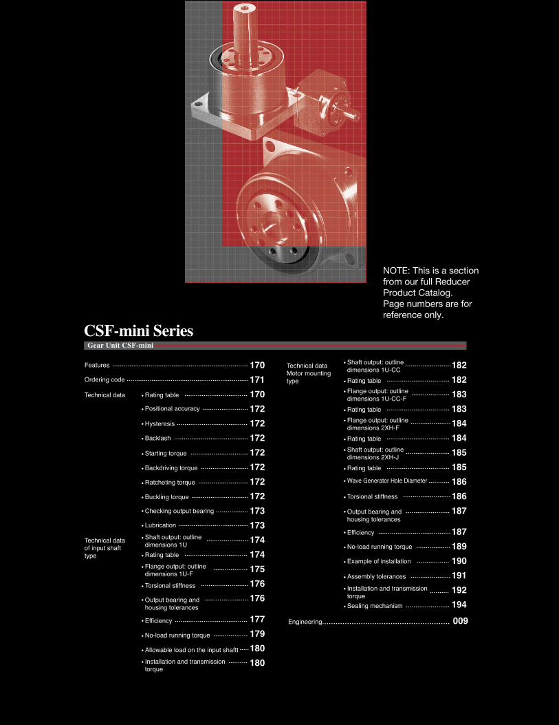
CSF-mini Series
Features
Technical data
Ordering code
Rating table
Technical data of input shaft type
Shaft output: outline dimensions 1URating tableFlange output: outline dimensions 1U-F
Torsional stiffness
Lubrication
Installation and transmission torque
Allowable load on the input shaftt
Positional accuracy
Hysteresis
Backlash
Starting torque
Backdriving torque
Ratcheting torque
Buckling torque
No-load running torque
Efficiency
Checking output bearing
Output bearing and housing tolerances
Technical data Motor mounting type
Rating table
Torsional stiffness
Installation and transmission torque
Shaft output: outline dimensions 2XH-J
Rating table
Shaft output: outline dimensions 1U-CC
Rating table
Flange output: outline dimensions 2XH-F
Rating table
Flange output: outline dimensions 1U-CC-F
Wave Generator Hole Diameter
No-load running torque
Example of installation
Assembly tolerances
Sealing mechanism
Efficiency
Output bearing and housing tolerances
Engineering........................................................ 009
NOTE: This is a section from our full Reducer Product Catalog. Page numbers are for reference only.

Engi
neer
ing
Dat
aC
ompo
nent
Set
sG
ear U
nits
Phas
e A
djus
ters
Gea
rhea
ds &
Act
uato
rs
Engi
neer
ing
Dat
aC
ompo
nent
Set
sG
ear U
nits
Phas
e A
djus
ters
Gea
rhea
ds &
Act
uato
rs
170
CSF - 14 - 100 - 2XH - F -
30
30
30
30
5
8
11
14
—
—
—
80
50
50
50
50
100
100
100
100
Nm Nm Nm Nm rpm rpm kgcm2
5
8
11
14
10000
8500
8500
8500
6500
3500
3500
3500
2.5×10⁻⁴
2.5×10⁻⁴
3.2×10⁻³
3.0×10⁻³
1.4×10⁻²
1.2×10⁻²
3.4×10⁻²
3.3×10⁻²
3050
1003050
1003050
100305080
100
0.250.40.60.91.82.42.23.55.04.05.47.87.8
0.50.91.41.83.34.84.58.3119.0182328
0.380.530.941.42.33.33.45.58.96.86.91111
0.91.82.73.36.69.08.5172517354754
Engi
neer
ing
Dat
aC
ompo
nent
Typ
eU
nit T
ype
Gea
r H
ead
Type
Diff
eren
tial G
ear
Engi
neer
ing
Dat
aC
ompo
nent
Typ
eU
nit T
ype
Gea
r H
ead
Type
Diff
eren
tial G
ear
SP
Features
CSF mini gearheads provide excellent positioning accuracy in a super-compact package.Compact 4-point contact bearing on the output side to support external loads. Available in four sizes and four ratios, the CSF mini gearheads feature shaft or flange outputs.
CSF-mini series
The HarmonicDrive® CSF-mini series consists of a wide variety of products including four sizes and six models.
Ordering Code
Series
CSF
Size Ratio*1 Model Special specification
1U= Input shaft, shaft output 1U-F= Input shaft, flange output 1U-CC= Square flange type, shaft output 1U-CC-F= Square flange type, flange output 2XH-J= Square flange type, shaft output2XH-F= Square flange type, flange output
SP= Special specification code
Blank = Standard product
*1 The reduction ratio value is based on the following configuration: Input: wave generator, fixed: circular spline, output: flexspline
Table 170-1
Rating table
Size Ratio
Rated Torque at input speed 2000rpm
Limit for Repeated Peak Torque
Limit for Average Torque
Limit for Momentary Peak Torque
Maximum Input Speed
Limit for Average Input Speed
Moment of Inertia
(1/4GD2)
Technical Data
Table 170-2
* The upper value of moment of inertia is for 1U, whereas, the lower value of it is for 2 XH.
■ Zero backlash■ Compact and lightweight■ High-torque capacity■ High-torsional stiffness■ Excellent positional accuracy■ Coaxial input and output
Features
This unit can be driven by a belt, coupling or a gear mounted on the input shaft. Available with shaft output or flange output.
Input shaft version
This gearhead is designed to be mounted to a motor, with the use of an adapter plate.
Shaft output: 1U Flange output: 1U-F
Square flange version: 2XH-J Flange output: 2XH-F
1U shaft output: 1U-CC 1U flange output: 1U-CC-F
Structure
Four-point contact ball bearing Circular spline
Input shaft (high-speed shaft)
Wave generator
Output shaft (low-speed shaft)
Output shaft (low-speed shaft)
Shaft output
Flexspline
Four-point contact ball bearing Circular spline
Wave generator(input part)
Output
Flexspline
* The rotational direction of the output shaft is opposite to that of the input shaft (wave generator) when the housing is fixed.
Fig. 171-1
Motor mounting type
Output flange
170170170170
Gear Unit CSF mini

Engi
neer
ing
Dat
aC
ompo
nent
Set
sG
ear U
nits
Phas
e A
djus
ters
Gea
rhea
ds &
Act
uato
rs
Engi
neer
ing
Dat
aC
ompo
nent
Set
sG
ear U
nits
Phas
e A
djus
ters
Gea
rhea
ds &
Act
uato
rs
171
CSF - 14 - 100 - 2XH - F -
30
30
30
30
5
8
11
14
—
—
—
80
50
50
50
50
100
100
100
100
Nm Nm Nm Nm rpm rpm kgcm2
5
8
11
14
10000
8500
8500
8500
6500
3500
3500
3500
2.5×10⁻⁴
2.5×10⁻⁴
3.2×10⁻³
3.0×10⁻³
1.4×10⁻²
1.2×10⁻²
3.4×10⁻²
3.3×10⁻²
3050
1003050
1003050
100305080
100
0.250.40.60.91.82.42.23.55.04.05.47.87.8
0.50.91.41.83.34.84.58.3119.0182328
0.380.530.941.42.33.33.45.58.96.86.91111
0.91.82.73.36.69.08.5172517354754
Engi
neer
ing
Dat
aC
ompo
nent
Typ
eU
nit T
ype
Gea
r H
ead
Type
Diff
eren
tial G
ear
Engi
neer
ing
Dat
aC
ompo
nent
Typ
eU
nit T
ype
Gea
r H
ead
Type
Diff
eren
tial G
ear
SP
Features
CSF mini gearheads provide excellent positioning accuracy in a super-compact package.Compact 4-point contact bearing on the output side to support external loads. Available in four sizes and four ratios, the CSF mini gearheads feature shaft or flange outputs.
CSF-mini series
The HarmonicDrive® CSF-mini series consists of a wide variety of products including four sizes and six models.
Ordering Code
Series
CSF
Size Ratio*1 Model Special specification
1U= Input shaft, shaft output 1U-F= Input shaft, flange output 1U-CC= Square flange type, shaft output 1U-CC-F= Square flange type, flange output 2XH-J= Square flange type, shaft output2XH-F= Square flange type, flange output
SP= Special specification code
Blank = Standard product
*1 The reduction ratio value is based on the following configuration: Input: wave generator, fixed: circular spline, output: flexspline
Table 170-1
Rating table
Size Ratio
Rated Torque at input speed 2000rpm
Limit for Repeated Peak Torque
Limit for Average Torque
Limit for Momentary Peak Torque
Maximum Input Speed
Limit for Average Input Speed
Moment of Inertia
(1/4GD2)
Technical Data
Table 170-2
* The upper value of moment of inertia is for 1U, whereas, the lower value of it is for 2 XH.
■ Zero backlash■ Compact and lightweight■ High-torque capacity■ High-torsional stiffness■ Excellent positional accuracy■ Coaxial input and output
Features
This unit can be driven by a belt, coupling or a gear mounted on the input shaft. Available with shaft output or flange output.
Input shaft version
This gearhead is designed to be mounted to a motor, with the use of an adapter plate.
Shaft output: 1U Flange output: 1U-F
Square flange version: 2XH-J Flange output: 2XH-F
1U shaft output: 1U-CC 1U flange output: 1U-CC-F
Structure
Four-point contact ball bearing Circular spline
Input shaft (high-speed shaft)
Wave generator
Output shaft (low-speed shaft)
Output shaft (low-speed shaft)
Shaft output
Flexspline
Four-point contact ball bearing Circular spline
Wave generator(input part)
Output
Flexspline
* The rotational direction of the output shaft is opposite to that of the input shaft (wave generator) when the housing is fixed.
Fig. 171-1
Motor mounting type
Output flange
171171171171
Gear Unit CSF mini

Engi
neer
ing
Dat
aC
ompo
nent
Set
sG
ear U
nits
Phas
e A
djus
ters
Gea
rhea
ds &
Act
uato
rs
Engi
neer
ing
Dat
aC
ompo
nent
Set
sG
ear U
nits
Phas
e A
djus
ters
Gea
rhea
ds &
Act
uato
rs
172172172172172
5 8 11 14
8 11 14
5 8 11 14
5 8 11 14
5 8 11 14
5 8 11 14
5 8 11 14
mm
dp
mm
R
Nm/rad N NNm×102N×102N
×10-4rad
arc min
×10-4rad
arc min
×10-4rad
arc min
8.73.08.73.08.73.0
8.73.05.82.05.82.0
8.73.05.82.05.82.0
8.73.05.82.02.91.0
30
50
80
100
×10-5rad
arc sec
×10-5rad
arc sec
×10-5rad
arc sec
×10-5rad
arc sec
28.6591735——8.718
23.849
14.124——7.315
29.160
17.536
11.2238.718
305080
100
0.530.40—
0.30
1.30.80—
0.59
3.42.0—1.5
6.44.12.82.5
305080
100
0.290.21—
0.27
0.700.55—
0.75
1.71.2—1.5
2.41.61.61.8
305080
100
2.73.2−
3.5
1112−14
2934−43
598811084
9.8 35 90 190
1.204.000.873.00
0.582.000.582.00
0.582.000.441.50
0.582.000.441.50
×10-3rad
arc min
×10-3rad
arc min
581114
4.857.39
11.4
13.520.527.535
9.1421.638.961.2
7.6319.035.458.5
0.893.466.613.2
7.41×10²
2.76×10³
7.41×10³
1.34×10⁴
90200300550
270630
11501800
Engi
neer
ing
Dat
aC
ompo
nent
Typ
eU
nit T
ype
Gea
r H
ead
Type
Diff
eren
tial G
ear
Engi
neer
ing
Dat
aC
ompo
nent
Typ
eU
nit T
ype
Gea
r H
ead
Type
Diff
eren
tial G
ear
LubricationThe standard CSF-mini gearheads are shipped already lubricated with grease. The table shows the grease that is used in the gear reducer and in the output bearing.
Gear Lubricated area Output bearing
Lubricant Harmonic Grease SK-2 Multemp HL-D
ManufacturerHarmonic Drive
Systems Kyodo Yushi
Base oil Refined oil Composite hydrocarbon oil
Thickening agent Lithium soap Lithium soap
Base Viscosity cSt (25oC) 295 280
Drop point 198oC 210oC
Appearance Green White
Positional accuracy See "Engineering data" for a description of terms.
Hysteresis See "Engineering data" for a description of terms.
Max. backlash See "Engineering data" for a description of terms.
Ratio
30
30
50
80 or more
50 or more
SpecificationSize
Ratio
Ratio
Size
Size
Table 172-1
Table 172-2
Table 172-3
RatioSize
RatioSize
Starting torque See "Engineering data" for a description of terms. Please use as reference values; the values vary based on use conditions.
Backdriving torque See "Engineering data" for a description of terms. Please use as reference values; the values vary based on use conditions.
Table 172-4Unit: Ncm
Table 172-5Unit: Nm
RatioSize
Ratcheting torque See "Engineering data" for a description of terms.
Buckling torque See "Engineering data" for a description of terms.
Table 172-6Unit: Nm
Table 172-7Unit: Nm
Size
All ratios
■ Checking procedure
■ Output bearing specifications
Table 173-1
Size
Pitch circle Offset
Basic dynamic rated load Basic static rated load
Allowable moment
load
Moment rigidity
Allowable radial load *
Allowable axial load
Basic rated load
A precision 4-point contact ball bearing is built into the CSF-mini series to directly support the external load.Check the maximum moment load, life of the 4-point contact ball bearing and static safety coefficient to fully maximize the performance of the CSF-mini series. See page 30 to 34 of "Engineering data" for each calculation formula.
(1) Checking the maximum moment load (Mmax)
(2) Checking the life
(3) Checking the static safety coefficient
Calculate the maximum moment load (Mmax).
Calculate the radial load (Frav) and the average axial load (Faav).
Calculate the static equivalent radial load coefficient (Po). Check the static safety coefficient. (fs)
Calculate the lifetimeCalculate the radial load coefficient (x) and the axial load coefficient (y).
Maximum moment load (Mmax) ≦ allowable moment (Mc)
Checking output bearing
Specifications
* Allowable radial load is the value on the center of output shaft side of both shaft type (1U) and that of gearhead shaft output type (2XH-J).* The value of the moment stiffness is the average value.
Table 173-2
Gear Unit CSF mini

Engi
neer
ing
Dat
aC
ompo
nent
Set
sG
ear U
nits
Phas
e A
djus
ters
Gea
rhea
ds &
Act
uato
rs
Engi
neer
ing
Dat
aC
ompo
nent
Set
sG
ear U
nits
Phas
e A
djus
ters
Gea
rhea
ds &
Act
uato
rs
173173173173173
5 8 11 14
8 11 14
5 8 11 14
5 8 11 14
5 8 11 14
5 8 11 14
5 8 11 14
mm
dp
mm
R
Nm/rad N NNm×102N×102N
×10-4rad
arc min
×10-4rad
arc min
×10-4rad
arc min
8.73.08.73.08.73.0
8.73.05.82.05.82.0
8.73.05.82.05.82.0
8.73.05.82.02.91.0
30
50
80
100
×10-5rad
arc sec
×10-5rad
arc sec
×10-5rad
arc sec
×10-5rad
arc sec
28.6591735——8.718
23.849
14.124——7.315
29.160
17.536
11.2238.718
305080
100
0.530.40—
0.30
1.30.80—
0.59
3.42.0—1.5
6.44.12.82.5
305080
100
0.290.21—
0.27
0.700.55—
0.75
1.71.2—1.5
2.41.61.61.8
305080
100
2.73.2−
3.5
1112−14
2934−43
598811084
9.8 35 90 190
1.204.000.873.00
0.582.000.582.00
0.582.000.441.50
0.582.000.441.50
×10-3rad
arc min
×10-3rad
arc min
581114
4.857.39
11.4
13.520.527.535
9.1421.638.961.2
7.6319.035.458.5
0.893.466.6
13.2
7.41×10²
2.76×10³
7.41×10³
1.34×10⁴
90200300550
270630
11501800
Engi
neer
ing
Dat
aC
ompo
nent
Typ
eU
nit T
ype
Gea
r H
ead
Type
Diff
eren
tial G
ear
Engi
neer
ing
Dat
aC
ompo
nent
Typ
eU
nit T
ype
Gea
r H
ead
Type
Diff
eren
tial G
ear
LubricationThe standard CSF-mini gearheads are shipped already lubricated with grease. The table shows the grease that is used in the gear reducer and in the output bearing.
Gear Lubricated area Output bearing
Lubricant Harmonic Grease SK-2 Multemp HL-D
ManufacturerHarmonic Drive
Systems Kyodo Yushi
Base oil Refined oil Composite hydrocarbon oil
Thickening agent Lithium soap Lithium soap
Base Viscosity cSt (25oC) 295 280
Drop point 198oC 210oC
Appearance Green White
Positional accuracy See "Engineering data" for a description of terms.
Hysteresis See "Engineering data" for a description of terms.
Max. backlash See "Engineering data" for a description of terms.
Ratio
30
30
50
80 or more
50 or more
SpecificationSize
Ratio
Ratio
Size
Size
Table 172-1
Table 172-2
Table 172-3
RatioSize
RatioSize
Starting torque See "Engineering data" for a description of terms. Please use as reference values; the values vary based on use conditions.
Backdriving torque See "Engineering data" for a description of terms. Please use as reference values; the values vary based on use conditions.
Table 172-4Unit: Ncm
Table 172-5Unit: Nm
RatioSize
Ratcheting torque See "Engineering data" for a description of terms.
Buckling torque See "Engineering data" for a description of terms.
Table 172-6Unit: Nm
Table 172-7Unit: Nm
Size
All ratios
■ Checking procedure
■ Output bearing specifications
Table 173-1
Size
Pitch circle Offset
Basic dynamic rated load Basic static rated load
Allowable moment
load
Moment rigidity
Allowable radial load *
Allowable axial load
Basic rated load
A precision 4-point contact ball bearing is built into the CSF-mini series to directly support the external load.Check the maximum moment load, life of the 4-point contact ball bearing and static safety coefficient to fully maximize the performance of the CSF-mini series. See page 30 to 34 of "Engineering data" for each calculation formula.
(1) Checking the maximum moment load (Mmax)
(2) Checking the life
(3) Checking the static safety coefficient
Calculate the maximum moment load (Mmax).
Calculate the radial load (Frav) and the average axial load (Faav).
Calculate the static equivalent radial load coefficient (Po). Check the static safety coefficient. (fs)
Calculate the lifetimeCalculate the radial load coefficient (x) and the axial load coefficient (y).
Maximum moment load (Mmax) ≦ allowable moment (Mc)
Checking output bearing
Specifications
* Allowable radial load is the value on the center of output shaft side of both shaft type (1U) and that of gearhead shaft output type (2XH-J).* The value of the moment stiffness is the average value.
Table 173-2
Gear Unit CSF mini

Engi
neer
ing
Dat
aC
ompo
nent
Set
sG
ear U
nits
Phas
e A
djus
ters
Gea
rhea
ds &
Act
uato
rs
Engi
neer
ing
Dat
aC
ompo
nent
Set
sG
ear U
nits
Phas
e A
djus
ters
Gea
rhea
ds &
Act
uato
rs
174
a
5 8 11 14
26.53713168
0.52.50.897
4.859.8519.513593
20.4±0.424.69.8233
M2×34
M2×320±0.42
2.635
4065.523
29.5130.52.52.618117.3
17.329209
165
30.7±0.468
15.5354
M3×44
M3×630±0.46
4.5130
5482.529.537160.53
3.921.5149
2239
26.512246
40.9±0.5010.520.5466
M3×54
M4×840±0.50
5.5240
6895.429.549.9161.53
8.42314
11.423.948
33.515328
51.1±0.5014
25.5586
M4×64
M5×1050±0.50
7.5440
5 8 11 14
26.5273168
0.52.50.81.77
4.8519.513593
20.4±0.429.8233
M2×34
M2×320.4±0.42
2.634
4045.5
329.5130.52.52.62.2117.329209165
30.7±0.4615.5354
M3×44
M3×630±0.46
4.5120
5456.53.537160.53
3.92.514939
26.512246
40.9±0.520.5466
M3×54
M4×840±0.5
5.5220
6870.44.5
49.9161.53
8.43.514
11.448
33.515328
51.1±0.525.5586
M4×64
M5×1050±0.5
7.5405
Engi
neer
ing
Dat
aC
ompo
nent
Typ
eU
nit T
ype
Gea
r H
ead
Type
Diff
eren
tial G
ear
Engi
neer
ing
Dat
aC
ompo
nent
Typ
eU
nit T
ype
Gea
r H
ead
Type
Diff
eren
tial G
ear
φABCDEFGHIJKLφM h7φNφO h6φPφQ h6□RSφTφUVWXY□ZaMass (g)
φABCDEFGHIJ KφM h7φNφO H7φPΦQ h6□R φT φUVWXY□ZaMass (g)
Fig. 174-1
Shaft output: outline dimension of 1U
Dimensions
You can download the CAD files from our website: harmonicdrive.net
Outline DimensionsFlange output: outline dimension of 1U-F
You can download the CAD files from our website: harmonicdrive.net
Outline Dimensions
(Note)V-W equally spaced
(Note)
X-Y equally spaced
Center of output shaft
Table 174-1Unit: mm
SymbolSize
Max
. dia
. of m
otor
* Refer to the confirmation drawing for detailed dimensions
Dimensions
V-W equally spaced
X-Y equally spaced
Table 175-1Unit: mm
SymbolSize
Max
. dia
. of m
otor
* Refer to the confirmation drawing for detailed dimensions
There is no positional relationship between the flat on the output shaft and the V-W tapped holes.
(Note)
Gear Unit CSF-1U

Engi
neer
ing
Dat
aC
ompo
nent
Set
sG
ear U
nits
Phas
e A
djus
ters
Gea
rhea
ds &
Act
uato
rs
Engi
neer
ing
Dat
aC
ompo
nent
Set
sG
ear U
nits
Phas
e A
djus
ters
Gea
rhea
ds &
Act
uato
rs
175
a
5 8 11 14
26.53713168
0.52.50.897
4.859.8519.513593
20.4±0.424.69.8233
M2×34
M2×320±0.42
2.635
4065.523
29.5130.52.52.618117.3
17.329209
165
30.7±0.468
15.5354
M3×44
M3×630±0.46
4.5130
5482.529.537160.53
3.921.5149
2239
26.512246
40.9±0.5010.520.5466
M3×54
M4×840±0.50
5.5240
6895.429.549.9161.53
8.42314
11.423.948
33.515328
51.1±0.5014
25.5586
M4×64
M5×1050±0.50
7.5440
5 8 11 14
26.5273
168
0.52.50.81.77
4.8519.513593
20.4±0.429.8233
M2×34
M2×320.4±0.42
2.634
4045.5
329.5130.52.52.62.2117.329209
165
30.7±0.4615.5354
M3×44
M3×630±0.46
4.5120
5456.53.537160.53
3.92.5149
3926.512246
40.9±0.520.5466
M3×54
M4×840±0.5
5.5220
6870.44.5
49.9161.53
8.43.514
11.448
33.515328
51.1±0.525.5586
M4×64
M5×1050±0.5
7.5405
Engi
neer
ing
Dat
aC
ompo
nent
Typ
eU
nit T
ype
Gea
r H
ead
Type
Diff
eren
tial G
ear
Engi
neer
ing
Dat
aC
ompo
nent
Typ
eU
nit T
ype
Gea
r H
ead
Type
Diff
eren
tial G
ear
φABCDEFGHIJKLφM h7φNφO h6φPφQ h6□RSφTφUVWXY□ZaMass (g)
φABCDEFGHIJ KφM h7φNφO H7φPΦQ h6□R φT φUVWXY□ZaMass (g)
Fig. 174-1
Shaft output: outline dimension of 1U
Dimensions
You can download the CAD files from our website: harmonicdrive.net
Outline DimensionsFlange output: outline dimension of 1U-F
You can download the CAD files from our website: harmonicdrive.net
Outline Dimensions
(Note)V-W equally spaced
(Note)
X-Y equally spaced
Center of output shaft
Table 174-1Unit: mm
SymbolSize
Max
. dia
. of m
otor
* Refer to the confirmation drawing for detailed dimensions
Dimensions
V-W equally spaced
X-Y equally spaced
Table 175-1Unit: mm
SymbolSize
Max
. dia
. of m
otor
* Refer to the confirmation drawing for detailed dimensions
There is no positional relationship between the flat on the output shaft and the V-W tapped holes.
(Note)
Gear Unit CSF-1U
Engi
neer
ing
Dat
aC
ompo
nent
Set
sG
ear U
nits
Phas
e A
djus
ters
Gea
rhea
ds &
Act
uato
rs
Engi
neer
ing
Dat
aC
ompo
nent
Set
sG
ear U
nits
Phas
e A
djus
ters
Gea
rhea
ds &
Act
uato
rs
176
5 8 11 14
1U-F1U 1U-F1U 1U-F1U 1U-F1U
5 8 11 14
1U-F1U 1U-F1U 1U-F1U 1U-F1U
T1
T2
K1
K2
K3
θ1
θ2
K1
K2
K3
θ1
θ2
K1
K2
K3
θ1
θ2
0.0100.0030.0130.0040.0160.0057.52.6196.4
0.0130.0040.0180.0050.0250.0075.62.0144.8
0.0200.0060.0270.0080.0300.0093.71.39.23.1
0.0090.0030.0110.0030.0120.0048.73.0227.5
0.0110.0030.0140.0040.0170.0056.92.4186.0
0.0150.0040.0180.0050.0200.0065.01.7134.4
0.0340.0100.0440.0130.0540.0168.63.0196.6
0.0440.0130.0670.0200.0840.0256.62.3144.7
0.0900.0270.1040.0310.1200.0363.21.17.72.6
0.0310.0090.0390.0120.0460.0149.53.2217.3
0.0390.0120.0560.0170.0670.0207.52.6165.4
0.0720.0210.0800.0240.0890.0274.11.49.83.4
0.0840.0250.1240.0370.1580.0479.53.3196.6
0.2210.0660.3000.0890.3200.0953.61.27.62.6
0.2670.0790.3330.0990.4320.1283.01.06.62.3
0.0770.0230.1090.0320.1340.040
103.6217.4
0.1770.0530.2250.0670.2360.0704.51.69.93.4
0.2060.0610.2430.0720.2910.0863.91.38.83.0
0.1880.0560.2350.0700.3350.100
113.63111
0.3350.1000.4680.1400.5680.1706.02.0165.6
0.4680.1400.6010.1790.7000.2094.31.5124.2
0.1720.0510.2100.0630.2860.085
124.03512
0.2860.0850.3780.1130.4400.1317.02.4206.8
0.3780.1130.4600.1370.5160.1545.31.8165.4
Nm
kgfm
Nm
kgfm
×104Nm/rad
kgfm/arc min
×104Nm/rad
kgfm/arc min
×104Nm/rad
kgfm/arc min
×10-4rad
arc min
×10-4rad
arc min
×104Nm/rad
kgfm/arc min
×104Nm/rad
kgfm/arc min
×104Nm/rad
kgfm/arc min
×10-4rad
arc min
×10-4rad
arc min
×104Nm/rad
kgfm/arc min
×104Nm/rad
kgfm/arc min
×104Nm/rad
kgfm/arc min
×10-4rad
arc min
×10-4rad
arc min
0.0750.00770.22
0.022
0.290.0300.75
0.077
0.800.0822.0
0.20
2.00.206.90.70
1.0
0.9
0.8
0.7
0.6
0.5
0.4
0.3
0 0.1 0.2 0.3 0.4 0.5 0.6 0.7 0.8 0.9 1.0
A
Aa
◎
AB
Bd
b
ec
φ
a
b
c
d
e
0.040
0.020
0.005
0.015
0.030
—
—
0.005
0.030
—
—
0.005
0.030
—
—
0.005
0.030
—
—
0.005
0.040
0.020
0.005
0.020
0.055
0.025
0.005
0.030
0.055
0.025
0.005
0.030
aA◎ bφ
A B
AB
dec
Engi
neer
ing
Dat
aC
ompo
nent
Typ
eU
nit T
ype
Gea
r H
ead
Type
Diff
eren
tial G
ear
Engi
neer
ing
Dat
aC
ompo
nent
Typ
eU
nit T
ype
Gea
r H
ead
Type
Diff
eren
tial G
ear
* T.I.R. Unit: mm
Fig. 176-1
Table 176-2
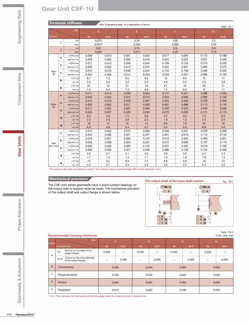
Mechanical precisionThe CSF-mini series gearheads have 4-point contact bearings on the output side to support external loads. The mechanical precision of the output shaft and output flange is shown below.
The output shaft of the input shaft version
Recommended housing tolerances
SymbolPrecision item
Size
Concentricity
Perpendicularity
Runout
Parallelism
* T.I.R.: This indicates the total reading of the dial gauge when the measuring part is rotated once.
* The values in this table are reference values. The minimum value is approximately 80% of the displayed value.
Torsional stiffness See "Engineering data" for a description of terms.
Ratio30
Ratio50
Ratio80 or more
Symbol
SizeTable 176-1
Efficiency
Example of calculation
The efficiency varies depending on the following conditions.■ Reduction ratio■ Input rotational speed■ Load torque■ Temperature■ Lubrication (type and quantity)
■ Efficiency compensation coefficient
Efficiency η (%) under the following condition is obtained from the example of CSF-8-100-1U.Input rotational speed: 1000 rpmLoad torque: 2.0 NmLubrication method: Grease lubricationLubricant temperature: 20oC
Since the rated torque of size 8 with a reduction ratio of 100 is 2.4 Nm (Ratings: Page 170), the torque ratio α is 0.83. (α=2.0/2.4≈0.83)
■ The efficiency compensation coefficient is Ke=0.99 from Graph 177-1.
■ Efficiency η at load torque 2.0 Nm: η=Ke・ηR=0.99 x 77%=76%
Graph 177-1
Table 177-1
Efficiency compensation coefficient
Com
pens
atio
n co
effic
ient
Ke
Torque ratio
Measurement condition
Grease lubricationLubricant
Name Harmonic Grease SK-2
Quality Recommended quantity
* When the load torque is higher than the rated torque, efficiency compensation value Ke is 1.
Torque ratio α = ─Load torqueRated torque
When the load torque is lower than the rated torque, the efficiency value decreases. Calculate compensation coefficient Ke from Graph 177-1.
Runout on the edge of the output flange
Runout on the inner diameter of the output flange
1U
1U-F
η =Ke・η R= Efficiency at the rated torque
η R
Load torque Rated torque in rating table (see Page 170)
Gear Unit CSF-1U

Engi
neer
ing
Dat
aC
ompo
nent
Set
sG
ear U
nits
Phas
e A
djus
ters
Gea
rhea
ds &
Act
uato
rs
Engi
neer
ing
Dat
aC
ompo
nent
Set
sG
ear U
nits
Phas
e A
djus
ters
Gea
rhea
ds &
Act
uato
rs
177
5 8 11 14
1U-F1U 1U-F1U 1U-F1U 1U-F1U
5 8 11 14
1U-F1U 1U-F1U 1U-F1U 1U-F1U
T1
T2
K1
K2
K3
θ1
θ2
K1
K2
K3
θ1
θ2
K1
K2
K3
θ1
θ2
0.0100.0030.0130.0040.0160.0057.52.6196.4
0.0130.0040.0180.0050.0250.0075.62.0144.8
0.0200.0060.0270.0080.0300.0093.71.39.23.1
0.0090.0030.0110.0030.0120.0048.73.0227.5
0.0110.0030.0140.0040.0170.0056.92.4186.0
0.0150.0040.0180.0050.0200.0065.01.7134.4
0.0340.0100.0440.0130.0540.0168.63.0196.6
0.0440.0130.0670.0200.0840.0256.62.3144.7
0.0900.0270.1040.0310.1200.0363.21.17.72.6
0.0310.0090.0390.0120.0460.0149.53.2217.3
0.0390.0120.0560.0170.0670.0207.52.6165.4
0.0720.0210.0800.0240.0890.0274.11.49.83.4
0.0840.0250.1240.0370.1580.0479.53.3196.6
0.2210.0660.3000.0890.3200.0953.61.27.62.6
0.2670.0790.3330.0990.4320.1283.01.06.62.3
0.0770.0230.1090.0320.1340.040
103.6217.4
0.1770.0530.2250.0670.2360.0704.51.69.93.4
0.2060.0610.2430.0720.2910.0863.91.38.83.0
0.1880.0560.2350.0700.3350.100
113.63111
0.3350.1000.4680.1400.5680.1706.02.0165.6
0.4680.1400.6010.1790.7000.2094.31.5124.2
0.1720.0510.2100.0630.2860.085
124.03512
0.2860.0850.3780.1130.4400.1317.02.4206.8
0.3780.1130.4600.1370.5160.1545.31.8165.4
Nm
kgfm
Nm
kgfm
×104Nm/rad
kgfm/arc min
×104Nm/rad
kgfm/arc min
×104Nm/rad
kgfm/arc min
×10-4rad
arc min
×10-4rad
arc min
×104Nm/rad
kgfm/arc min
×104Nm/rad
kgfm/arc min
×104Nm/rad
kgfm/arc min
×10-4rad
arc min
×10-4rad
arc min
×104Nm/rad
kgfm/arc min
×104Nm/rad
kgfm/arc min
×104Nm/rad
kgfm/arc min
×10-4rad
arc min
×10-4rad
arc min
0.0750.00770.22
0.022
0.290.0300.75
0.077
0.800.0822.0
0.20
2.00.206.90.70
1.0
0.9
0.8
0.7
0.6
0.5
0.4
0.3
0 0.1 0.2 0.3 0.4 0.5 0.6 0.7 0.8 0.9 1.0
A
Aa
◎
AB
Bd
b
ec
φ
a
b
c
d
e
0.040
0.020
0.005
0.015
0.030
—
—
0.005
0.030
—
—
0.005
0.030
—
—
0.005
0.030
—
—
0.005
0.040
0.020
0.005
0.020
0.055
0.025
0.005
0.030
0.055
0.025
0.005
0.030
aA◎ bφ
A B
AB
dec
Engi
neer
ing
Dat
aC
ompo
nent
Typ
eU
nit T
ype
Gea
r H
ead
Type
Diff
eren
tial G
ear
Engi
neer
ing
Dat
aC
ompo
nent
Typ
eU
nit T
ype
Gea
r H
ead
Type
Diff
eren
tial G
ear
* T.I.R. Unit: mm
Fig. 176-1
Table 176-2
Mechanical precisionThe CSF-mini series gearheads have 4-point contact bearings on the output side to support external loads. The mechanical precision of the output shaft and output flange is shown below.
The output shaft of the input shaft version
Recommended housing tolerances
SymbolPrecision item
Size
Concentricity
Perpendicularity
Runout
Parallelism
* T.I.R.: This indicates the total reading of the dial gauge when the measuring part is rotated once.
* The values in this table are reference values. The minimum value is approximately 80% of the displayed value.
Torsional stiffness See "Engineering data" for a description of terms.
Ratio30
Ratio50
Ratio80 or more
Symbol
SizeTable 176-1
Efficiency
Example of calculation
The efficiency varies depending on the following conditions.■ Reduction ratio■ Input rotational speed■ Load torque■ Temperature■ Lubrication (type and quantity)
■ Efficiency compensation coefficient
Efficiency η (%) under the following condition is obtained from the example of CSF-8-100-1U.Input rotational speed: 1000 rpmLoad torque: 2.0 NmLubrication method: Grease lubricationLubricant temperature: 20oC
Since the rated torque of size 8 with a reduction ratio of 100 is 2.4 Nm (Ratings: Page 170), the torque ratio α is 0.83. (α=2.0/2.4≈0.83)
■ The efficiency compensation coefficient is Ke=0.99 from Graph 177-1.
■ Efficiency η at load torque 2.0 Nm: η=Ke・ηR=0.99 x 77%=76%
Graph 177-1
Table 177-1
Efficiency compensation coefficient
Com
pens
atio
n co
effic
ient
KeTorque ratio
Measurement condition
Grease lubricationLubricant
Name Harmonic Grease SK-2
Quality Recommended quantity
* When the load torque is higher than the rated torque, efficiency compensation value Ke is 1.
Torque ratio α = ─Load torqueRated torque
When the load torque is lower than the rated torque, the efficiency value decreases. Calculate compensation coefficient Ke from Graph 177-1.
Runout on the edge of the output flange
Runout on the inner diameter of the output flange
1U
1U-F
η =Ke・η R= Efficiency at the rated torque
η R
Load torque Rated torque in rating table (see Page 170)
Gear Unit CSF-1U

Engi
neer
ing
Dat
aC
ompo
nent
Set
sG
ear U
nits
Phas
e A
djus
ters
Gea
rhea
ds &
Act
uato
rs
Engi
neer
ing
Dat
aC
ompo
nent
Set
sG
ear U
nits
Phas
e A
djus
ters
Gea
rhea
ds &
Act
uato
rs
178
5
81114
100.0
10.0
1.0
0.1-10 10 20 30 400
5
81114
100.0
10.0
1.0
0.1-10 10 20 30 400
5
8
1114
100.0
10.0
1.0
0.1-10 10 20 30 400
5
81114
100.0
10.0
1.0
0.1-10 10 20 30 400
1009080706050403020100-10 100 20 4030
100908070605040302010
0-10 100 20 4030
100908070605040302010
0-10 100 20 4030
1009080706050403020100-10 100 20 4030
1009080706050403020100-10 100 20 4030
1009080706050403020100-10 100 20 4030
-10 100 20 4030
9080706050403020100
-10 100 20 4030
9080706050403020100
-10 100 20 4030
9080706050403020100
1009080706050403020100-10 100 20 4030
1009080706050403020100-10 100 20 4030
1009080706050403020100-10 100 20 4030
500rpm 1000rpm 2000rpm 3500rpm
30 50 80
581114
0.260.440.811.33
0.110.190.360.58
———0.1
Engi
neer
ing
Dat
aC
ompo
nent
Typ
eU
nit T
ype
Gea
r H
ead
Type
Diff
eren
tial G
ear
Engi
neer
ing
Dat
aC
ompo
nent
Typ
eU
nit T
ype
Gea
r H
ead
Type
Diff
eren
tial G
ear
Graph 178-1Ratio 30
Size 5
Effic
ienc
y (%
)
Graph 178-2Ratio 50
Effic
ienc
y (%
)
Graph 178-3Ratio 100
Effic
ienc
y (%
)
Graph 178-4
Ratio 30Size 8
Effic
ienc
y (%
)
Graph 178-5
Ratio 50
Effic
ienc
y (%
)Graph 178-6
Ratio 100
Effic
ienc
y (%
)Graph 178-7
Ratio 30Size 11
Effic
ienc
y (%
)
Graph 178-8Ratio 50
Effic
ienc
y (%
)
Graph 178-9Ratio 100
Effic
ienc
y (%
)
Graph 178-10
Ratio 30Size 14
Effic
ienc
y (%
)
Graph 178-11
Ratio 50
Effic
ienc
y (%
)
Graph 178-12
Ratio 80 and 100
Effic
ienc
y (%
)
■ Efficiency at rated torque
Input rotational speed
Table 179-1
No-load running torqueNo-load running torque is the torque which is required to rotate the input side (high speed side), when there is no load on the output side (low speed side).
Measurement Condition
Lubrication type Grease lubrication NameTorque value is measured after 2 hours at 2000rpm input.
Harmonic Grease SK-2
Ratio
SizeRatio
Table 179-2Unit: Ncm
■ Compensation Value in Each RatioNo-load running torque of the gear varies with ratio. Graphs 179-1 to 179-4 show the values for a reduction ratio of 100. For other gear ratios, add the compensation values in the right-hand table (Table 179-2).
No-Load Torque Running Torque Compensation Value
■ No-load running torque for a reduction ratio of 100
Input speed: 500rpm
Graph 179-1
No-
load
runn
ing
torq
ue (N
cm)
Size
Ambient Temperature (oC) Ambient Temperature (oC)
Ambient Temperature (oC) Ambient Temperature (oC)
Input speed: 1000rpm
Graph 179-2
No-
load
runn
ing
torq
ue (N
cm)
Size
Input speed: 2000rpm
Graph 179-3
No-
load
runn
ing
torq
ue (N
cm)
Size
Input speed: 3500rpm
Graph 179-4
No-
load
runn
ing
torq
ue (N
cm)
Size
*The values in this graph are average values (X).
Ambient Temperature (oC) Ambient Temperature (oC) Ambient Temperature (oC)
Ambient Temperature (oC) Ambient Temperature (oC) Ambient Temperature (oC)
Ambient Temperature (oC) Ambient Temperature (oC) Ambient Temperature (oC)
Ambient Temperature (oC) Ambient Temperature (oC) Ambient Temperature (oC)
Gear Unit CSF-1U

Engi
neer
ing
Dat
aC
ompo
nent
Set
sG
ear U
nits
Phas
e A
djus
ters
Gea
rhea
ds &
Act
uato
rs
Engi
neer
ing
Dat
aC
ompo
nent
Set
sG
ear U
nits
Phas
e A
djus
ters
Gea
rhea
ds &
Act
uato
rs
179
5
81114
100.0
10.0
1.0
0.1-10 10 20 30 400
5
81114
100.0
10.0
1.0
0.1-10 10 20 30 400
5
8
1114
100.0
10.0
1.0
0.1-10 10 20 30 400
5
81114
100.0
10.0
1.0
0.1-10 10 20 30 400
1009080706050403020100-10 100 20 4030
100908070605040302010
0-10 100 20 4030
100908070605040302010
0-10 100 20 4030
1009080706050403020100-10 100 20 4030
1009080706050403020100-10 100 20 4030
1009080706050403020100-10 100 20 4030
-10 100 20 4030
9080706050403020100
-10 100 20 4030
9080706050403020100
-10 100 20 4030
9080706050403020100
1009080706050403020100-10 100 20 4030
1009080706050403020100-10 100 20 4030
1009080706050403020100-10 100 20 4030
500rpm 1000rpm 2000rpm 3500rpm
30 50 80
58
1114
0.260.440.811.33
0.110.190.360.58
———0.1
Engi
neer
ing
Dat
aC
ompo
nent
Typ
eU
nit T
ype
Gea
r H
ead
Type
Diff
eren
tial G
ear
Engi
neer
ing
Dat
aC
ompo
nent
Typ
eU
nit T
ype
Gea
r H
ead
Type
Diff
eren
tial G
ear
Graph 178-1Ratio 30
Size 5
Effic
ienc
y (%
)
Graph 178-2Ratio 50
Effic
ienc
y (%
)
Graph 178-3Ratio 100
Effic
ienc
y (%
)
Graph 178-4
Ratio 30Size 8
Effic
ienc
y (%
)
Graph 178-5
Ratio 50
Effic
ienc
y (%
)
Graph 178-6
Ratio 100
Effic
ienc
y (%
)
Graph 178-7Ratio 30
Size 11
Effic
ienc
y (%
)
Graph 178-8Ratio 50
Effic
ienc
y (%
)
Graph 178-9Ratio 100
Effic
ienc
y (%
)
Graph 178-10
Ratio 30Size 14
Effic
ienc
y (%
)
Graph 178-11
Ratio 50
Effic
ienc
y (%
)
Graph 178-12
Ratio 80 and 100
Effic
ienc
y (%
)
■ Efficiency at rated torque
Input rotational speed
Table 179-1
No-load running torqueNo-load running torque is the torque which is required to rotate the input side (high speed side), when there is no load on the output side (low speed side).
Measurement Condition
Lubrication type Grease lubrication NameTorque value is measured after 2 hours at 2000rpm input.
Harmonic Grease SK-2
Ratio
SizeRatio
Table 179-2Unit: Ncm
■ Compensation Value in Each RatioNo-load running torque of the gear varies with ratio. Graphs 179-1 to 179-4 show the values for a reduction ratio of 100. For other gear ratios, add the compensation values in the right-hand table (Table 179-2).
No-Load Torque Running Torque Compensation Value
■ No-load running torque for a reduction ratio of 100
Input speed: 500rpm
Graph 179-1
No-
load
runn
ing
torq
ue (N
cm)
Size
Ambient Temperature (oC) Ambient Temperature (oC)
Ambient Temperature (oC) Ambient Temperature (oC)
Input speed: 1000rpm
Graph 179-2N
o-lo
ad ru
nnin
g to
rque
(Ncm
)
Size
Input speed: 2000rpm
Graph 179-3
No-
load
runn
ing
torq
ue (N
cm)
Size
Input speed: 3500rpm
Graph 179-4
No-
load
runn
ing
torq
ue (N
cm)
Size
*The values in this graph are average values (X).
Ambient Temperature (oC) Ambient Temperature (oC) Ambient Temperature (oC)
Ambient Temperature (oC) Ambient Temperature (oC) Ambient Temperature (oC)
Ambient Temperature (oC) Ambient Temperature (oC) Ambient Temperature (oC)
Ambient Temperature (oC) Ambient Temperature (oC) Ambient Temperature (oC)
Gear Unit CSF-1U

Engi
neer
ing
Dat
aC
ompo
nent
Set
sG
ear U
nits
Phas
e A
djus
ters
Gea
rhea
ds &
Act
uato
rs
Engi
neer
ing
Dat
aC
ompo
nent
Set
sG
ear U
nits
Phas
e A
djus
ters
Gea
rhea
ds &
Act
uato
rs
180
a b
Fr
Fa+
0 2 4 6 8 10
10
20
30
40
5 8 11 14
4
M2
23
0.25
2.4
3.5
4
M3
35
0.85
3.6
12
4
M4
46
2.0
4.8
29
4
M5
58
3.96
6.0
57
Nm
mm
Nm
mm
b(mm) Fr(N)a(mm)Cor(N)Cr(N)Cor(N)Cr(N)58
1114
SSLF-630DDMR126
6896900ZZ
L-520WO2MR83624
605ZZ
196715
13302700
59292665
1270
176560
13001330
54170485505
10.816.6520.6
28.25
9.2518
21.924.25
8102030
5 8 11 14
3
M2
9.8
0.54
2
4
M3
15.5
2.0
13
6
M3
20.5
2.0
26
6
M4
25.5
4.6
55
Nm
Nm
mm
Engi
neer
ing
Dat
aC
ompo
nent
Typ
eU
nit T
ype
Gea
r H
ead
Type
Diff
eren
tial G
ear
Engi
neer
ing
Dat
aC
ompo
nent
Typ
eU
nit T
ype
Gea
r H
ead
Type
Diff
eren
tial G
ear
Table 180-1
Performance data for the input bearing
The input shaft type is supported by two deep groove single row ball bearings. Please check the loading on the input shaft to make sure that it is acceptable. Figure 180-1, Table 244-1, Graph 180-1 show the points of application of forces, which determine the maximum allowable radial and axial loads as indicated. The values in Graph 180-1 are valid for an average input speed of 2000 rpm and a mean bearing life of L10=7000h.
■ Performance data for the input bearing
Example: When an 8-N axial load (Fa) is applied to the size 14 input shaft, the value of the maximum allowable radial load (Fr) is 20 N.
Specification for Input Bearing
Size
Bearing A
ModelBasic dynamic
rated loadBasic static rated load
Bearing B
ModelBasic dynamic
rated loadBasic static rated load
Distance between
bearings a
Overhang length of the input shaft b
Maximum radial load
Fig. 180-1
Fa: Axial load (N)Fr: Radial load (N)
Bearing ABearing B
Supporting point of the roller bearing Graph 180-1Relation between the radial load and the axial load
Axial load Fa (N)
Radi
al lo
ad F
r (N
)Size: 14
Size: 11Size: 8
Size: 5
Table 180-2
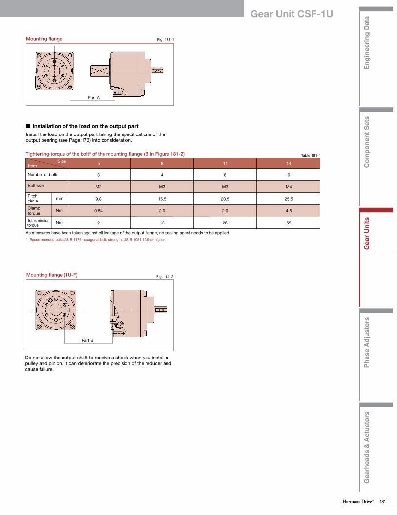
Installation and transmission torque
Check the mating surface for flatness and any burrs prior to mounting the CSF-mini product. Use the proper screws and tightening torque as specified in Table 180-2.
■ Installation on the equipment
Tightening torque of the bolt* of the mounting flange (A in Figure 181-1)
* Recommended bolt: JIS B 1176 hexagonal bolt,strength: JIS B 1051 12.9 or higher.
Number of bolts
Bolt size
PitchcircleClamp torque
Screw
Transmission torque
SizeItem
Fig. 181-1Mounting flange
Part A
Table 181-1Tightening torque of the bolt* of the mounting flange (B in Figure 181-2)
* Recommended bolt: JIS B 1176 hexagonal bolt, strength: JIS B 1051 12.9 or higher.
Number of bolts
Bolt size
PitchcircleClamp torqueTransmission torque
SizeItem
Fig. 181-2Mounting flange (1U-F)
Part B
Do not allow the output shaft to receive a shock when you install a pulley and pinion. It can deteriorate the precision of the reducer and cause failure.
Install the load on the output part taking the specifications of the output bearing (see Page 173) into consideration.
■ Installation of the load on the output part
As measures have been taken against oil leakage of the output flange, no sealing agent needs to be applied.
Gear Unit CSF-1U
Engi
neer
ing
Dat
aC
ompo
nent
Set
sG
ear U
nits
Phas
e A
djus
ters
Gea
rhea
ds &
Act
uato
rs
Engi
neer
ing
Dat
aC
ompo
nent
Set
sG
ear U
nits
Phas
e A
djus
ters
Gea
rhea
ds &
Act
uato
rs
181
a b
Fr
Fa+
0 2 4 6 8 10
10
20
30
40
5 8 11 14
4
M2
23
0.25
2.4
3.5
4
M3
35
0.85
3.6
12
4
M4
46
2.0
4.8
29
4
M5
58
3.96
6.0
57
Nm
mm
Nm
mm
b(mm) Fr(N)a(mm)Cor(N)Cr(N)Cor(N)Cr(N)58
1114
SSLF-630DDMR126
6896900ZZ
L-520WO2MR83624
605ZZ
196715
13302700
59292665
1270
176560
13001330
54170485505
10.816.6520.6
28.25
9.2518
21.924.25
8102030
5 8 11 14
3
M2
9.8
0.54
2
4
M3
15.5
2.0
13
6
M3
20.5
2.0
26
6
M4
25.5
4.6
55
Nm
Nm
mm
Engi
neer
ing
Dat
aC
ompo
nent
Typ
eU
nit T
ype
Gea
r H
ead
Type
Diff
eren
tial G
ear
Engi
neer
ing
Dat
aC
ompo
nent
Typ
eU
nit T
ype
Gea
r H
ead
Type
Diff
eren
tial G
ear
Table 180-1
Performance data for the input bearing
The input shaft type is supported by two deep groove single row ball bearings. Please check the loading on the input shaft to make sure that it is acceptable. Figure 180-1, Table 244-1, Graph 180-1 show the points of application of forces, which determine the maximum allowable radial and axial loads as indicated. The values in Graph 180-1 are valid for an average input speed of 2000 rpm and a mean bearing life of L10=7000h.
■ Performance data for the input bearing
Example: When an 8-N axial load (Fa) is applied to the size 14 input shaft, the value of the maximum allowable radial load (Fr) is 20 N.
Specification for Input Bearing
Size
Bearing A
ModelBasic dynamic
rated loadBasic static rated load
Bearing B
ModelBasic dynamic
rated loadBasic static rated load
Distance between
bearings a
Overhang length of the input shaft b
Maximum radial load
Fig. 180-1
Fa: Axial load (N)Fr: Radial load (N)
Bearing ABearing B
Supporting point of the roller bearing Graph 180-1Relation between the radial load and the axial load
Axial load Fa (N)
Radi
al lo
ad F
r (N
)
Size: 14
Size: 11Size: 8
Size: 5
Table 180-2
Installation and transmission torque
Check the mating surface for flatness and any burrs prior to mounting the CSF-mini product. Use the proper screws and tightening torque as specified in Table 180-2.
■ Installation on the equipment
Tightening torque of the bolt* of the mounting flange (A in Figure 181-1)
* Recommended bolt: JIS B 1176 hexagonal bolt,strength: JIS B 1051 12.9 or higher.
Number of bolts
Bolt size
PitchcircleClamp torque
Screw
Transmission torque
SizeItem
Fig. 181-1Mounting flange
Part A
Table 181-1Tightening torque of the bolt* of the mounting flange (B in Figure 181-2)
* Recommended bolt: JIS B 1176 hexagonal bolt, strength: JIS B 1051 12.9 or higher.
Number of bolts
Bolt size
PitchcircleClamp torqueTransmission torque
SizeItem
Fig. 181-2Mounting flange (1U-F)
Part B
Do not allow the output shaft to receive a shock when you install a pulley and pinion. It can deteriorate the precision of the reducer and cause failure.
Install the load on the output part taking the specifications of the output bearing (see Page 173) into consideration.
■ Installation of the load on the output part
As measures have been taken against oil leakage of the output flange, no sealing agent needs to be applied.
Gear Unit CSF-1U

Engi
neer
ing
Dat
aC
ompo
nent
Set
sG
ear U
nits
Phas
e A
djus
ters
Gea
rhea
ds &
Act
uato
rs
Engi
neer
ing
Dat
aC
ompo
nent
Set
sG
ear U
nits
Phas
e A
djus
ters
Gea
rhea
ds &
Act
uato
rs
182
φ
φ φ φ φ φ φ
φ
φφ
φφ
φφ φ φφ
φ
H7
5 8 11 14 5 8 11 14
+0.2 00.4
+0.2 00.4
26.530.513
12.74.80.52.51.3922
M2×36
4.859.8519.5135
173
20.4±0.429.8234.6
22.53
M2×34
M2×34
M2×327ー27
405123
21.56.50.52.51.51822
M2×3127.3
17.329209
263
30.7±0.4615.5358
344
M3×44
M3×64
M2.5×548.74.2111
5464.329.526.58.30.532
21.532
M3×4169
2239
26.512355
40.9±0.520.546
10.5466
M3×54
M4×84
M3×662.16.1176
6870
29.5337.51.53
2.5232.52
M3×417.611.423.948
33.515436
51.1±0.525.55814586
M4×64
M5×104
M4×870.47.9335
26.520.5
312.74.80.52.51.31.722
M2×36
4.8519.5135173
20.4±0.429.823
22.53
M2×34
M2×34
M2×317ー25
40313
21.56.50.52.51.52.222
M2×3127.329209263
30.7±0.4615.535344
M3×44
M3×64
M2.5×528.74.2100
54 38.33.526.58.30.532
2.532
M3×416939
26.512355
40.9±0.520.546466
M3×54
M4×84
M3×636.16.1150
68454.5337.51.53
2.53.52.52
M3×417.611.448
33.515436
51.1±0.525.558586
M4×64
M5×104
M4×845.47.9295
0-0.3
0-0.7
0-0.8
0-0.2
0-0.3
0-0.7
0-0.8
0-0.3
0-0.7
0-0.8
0-0.3
0-0.2
0-0.7
0-0.8
Engi
neer
ing
Dat
aC
ompo
nent
Typ
eU
nit T
ype
Gea
r H
ead
Type
Diff
eren
tial G
ear
Engi
neer
ing
Dat
aC
ompo
nent
Typ
eU
nit T
ype
Gea
r H
ead
Type
Diff
eren
tial G
ear
φAB*CDE*FGHIJKLMNOφP h7φQφR h6φS h6φT H7□UφVφWXφYabcdefg*h*Mass (g)
Flange output: outline dimensions 1U-CC-F
You can download the CAD files from our website: harmonicdrive.net
SymbolSize
Unit : mmTable 183-1Dimensions
Wave generator is removed when the product is delivered.
Fig. 182-1
c-d equallyspaced
e-f equallyspaceda-b equally
spacedWith locking screw
Max
. dia.
of m
otor
Wave generator installation dimension for size 5
Wave generatorReverse for motor with long output shaft
Shaft output: outline dimensions 1U-CC
You can download the CAD files from our website: harmonicdrive.net
Symbol SizeUnit : mm
Table 182-1Dimensions
*The B, E, g and h dimensions indicated by an asterisk are the mounting positions in the shaft direction and allowance of the three parts (wave generator, flexspline, circular spline). Strictly observe these dimensions as they affect the performance and strength.
Wave generator is removed when the product is delivered.
Center of output shaft
Fig. 183-1
c-d equally spaced
e-f equallyspaced
a-b equallyspaced
With locking screw
Max
. dia.
of m
otor
Wave generator installation dimension for size 5
Wave generatorReverse for motor with long output shaft
φAB*CDE*FGHIJKLMNφP h7φQφR H7φS h6φT H7□UφVφWφYabcdefg*h*Mass (g)
Outline Dimensions
*The B, E, g and h dimensions indicated by an asterisk are the mounting positions in the shaft direction and allowance of the three parts (wave generator, flexspline, circular spline). Strictly observe these dimensions as they affect the performance and strength.
* Please refer to the confirmation drawing for detailed dimensions. The dimension tolerances that are not specified vary depending on the manufacturing method. Please check the confirmation drawing or contact us for dimension tolerances not shown on the drawing.* See Fig. 040-3 on Page 040 for the shapes of the wave generator.
* Please refer to the confirmation drawing for detailed dimensions. The dimension tolerances that are not specified vary depending on the manufacturing method. Please check the confirmation drawing or contact us for dimension tolerances not shown on the drawing.* See Fig. 040-3 on Page 040 for the shapes of the wave generator.
CSF-2XH/CSF-1U-CC

Engi
neer
ing
Dat
aC
ompo
nent
Set
sG
ear U
nits
Phas
e A
djus
ters
Gea
rhea
ds &
Act
uato
rs
Engi
neer
ing
Dat
aC
ompo
nent
Set
sG
ear U
nits
Phas
e A
djus
ters
Gea
rhea
ds &
Act
uato
rs
183
φ
φ φ φ φ φ φ
φ
φφ
φφ
φφ φ φφ
φ
H7
5 8 11 14 5 8 11 14
+0.2 00.4
+0.2 00.4
26.530.513
12.74.80.52.51.3922
M2×36
4.859.8519.5135
173
20.4±0.429.8234.6
22.53
M2×34
M2×34
M2×327ー27
405123
21.56.50.52.51.51822
M2×3127.3
17.329209
263
30.7±0.4615.5358
344
M3×44
M3×64
M2.5×548.74.2111
5464.329.526.58.30.532
21.532
M3×4169
2239
26.512355
40.9±0.520.546
10.5466
M3×54
M4×84
M3×662.16.1176
6870
29.5337.51.53
2.5232.52
M3×417.611.423.948
33.515436
51.1±0.525.55814586
M4×64
M5×104
M4×870.47.9335
26.520.5
312.74.80.52.51.31.722
M2×36
4.8519.5135
173
20.4±0.429.823
22.53
M2×34
M2×34
M2×317ー25
40313
21.56.50.52.51.52.222
M2×3127.329209
263
30.7±0.4615.535344
M3×44
M3×64
M2.5×528.74.2100
54 38.33.5
26.58.30.532
2.532
M3×4169
3926.512355
40.9±0.520.546466
M3×54
M4×84
M3×636.16.1150
68454.5337.51.53
2.53.52.52
M3×417.611.448
33.515436
51.1±0.525.558586
M4×64
M5×104
M4×845.47.9295
0-0.3
0-0.7
0-0.8
0-0.2
0-0.3
0-0.7
0-0.8
0-0.3
0-0.7
0-0.8
0-0.3
0-0.2
0-0.7
0-0.8
Engi
neer
ing
Dat
aC
ompo
nent
Typ
eU
nit T
ype
Gea
r H
ead
Type
Diff
eren
tial G
ear
Engi
neer
ing
Dat
aC
ompo
nent
Typ
eU
nit T
ype
Gea
r H
ead
Type
Diff
eren
tial G
ear
φAB*CDE*FGHIJKLMNOφP h7φQφR h6φS h6φT H7□UφVφWXφYabcdefg*h*Mass (g)
Flange output: outline dimensions 1U-CC-F
You can download the CAD files from our website: harmonicdrive.net
SymbolSize
Unit : mmTable 183-1Dimensions
Wave generator is removed when the product is delivered.
Fig. 182-1
c-d equallyspaced
e-f equallyspaceda-b equally
spacedWith locking screw
Max
. dia.
of m
otor
Wave generator installation dimension for size 5
Wave generatorReverse for motor with long output shaft
Shaft output: outline dimensions 1U-CC
You can download the CAD files from our website: harmonicdrive.net
Symbol SizeUnit : mm
Table 182-1Dimensions
*The B, E, g and h dimensions indicated by an asterisk are the mounting positions in the shaft direction and allowance of the three parts (wave generator, flexspline, circular spline). Strictly observe these dimensions as they affect the performance and strength.
Wave generator is removed when the product is delivered.
Center of output shaft
Fig. 183-1
c-d equally spaced
e-f equallyspaced
a-b equallyspaced
With locking screw
Max
. dia.
of m
otor
Wave generator installation dimension for size 5
Wave generatorReverse for motor with long output shaft
φAB*CDE*FGHIJKLMNφP h7φQφR H7φS h6φT H7□UφVφWφYabcdefg*h*Mass (g)
Outline Dimensions
*The B, E, g and h dimensions indicated by an asterisk are the mounting positions in the shaft direction and allowance of the three parts (wave generator, flexspline, circular spline). Strictly observe these dimensions as they affect the performance and strength.
* Please refer to the confirmation drawing for detailed dimensions. The dimension tolerances that are not specified vary depending on the manufacturing method. Please check the confirmation drawing or contact us for dimension tolerances not shown on the drawing.* See Fig. 040-3 on Page 040 for the shapes of the wave generator.
* Please refer to the confirmation drawing for detailed dimensions. The dimension tolerances that are not specified vary depending on the manufacturing method. Please check the confirmation drawing or contact us for dimension tolerances not shown on the drawing.* See Fig. 040-3 on Page 040 for the shapes of the wave generator.
CSF-2XH/CSF-1U-CC

Engi
neer
ing
Dat
aC
ompo
nent
Set
sG
ear U
nits
Phas
e A
djus
ters
Gea
rhea
ds &
Act
uato
rs
Engi
neer
ing
Dat
aC
ompo
nent
Set
sG
ear U
nits
Phas
e A
djus
ters
Gea
rhea
ds &
Act
uato
rs
184
φW
φV
C DF
J H
K
L-M
IN
z G
φA
φU
h6
φT
h6 φV
H7
φR
h7
φS
Q
φY
φX
□W
5 8 11 14
B*□U D*
NN
e*
e*f*
φP
h7 φT
H7
φR
H7
φS
h6
φQ
φA
M
O
K-L
J
CE F
HIG
J
0.4+0.2 0
5 8 11 14
B*E*
OPO
g*g*h*
K
0.4+0.2 0
2920.515.74.8 -0.2
12.73
1.32
0.522
M2×31.76
4.8520.5135
173
22±0.429.8253
M2×32
M22
2.317ー
18.90×0.7025
43.531
24.56.5 -0.3
195.51.53
0.522
M2×32.2127.331209
263
32±0.4615.537.5
4M3X4
2M32
3.428.74.2 -0.3
28.20×1.00100
5838.330
8.3 -0.7
23.56.523
0.532
M3×42.5169
40.526.512355
43±0.5020.5506
M3×52
M42
4.536.16.1 -0.7
38.00×1.50150
7345
37.57.5 -0.8
289.52.55
1.52.52
M3×43.517.611.451
33.515436
53±0.5025.5626
M4×62
M52
5.545.47.9 -0.8
48.00×1.00295
0 0 0
0 0 0 0
2930.510
15.74.8 -0.2
12.73
1.30.5222
M2×396
4.859.8520.5135173
22±0.429.8254.63
M2×32
M22
2.327ー
18.90×0.7027
43.55120
24.56.5 -0.3
195.51.50.5322
M2×318127.317.331209263
32±0.4615.537.5
84
M3×42
M32
3.448.74.2 -0.3
28.20×1.00111
5864.32630
8.3 -0.7
23.56.52
0.5332
M3×421.516922
40.526.512355
43±0.5020.550
10.56
M3×52
M42
4.562.16.1 -0.7
38.00×1.50176
737025
37.57.5 -0.8
289.52.51.55
2.52
M3×423
17.611.423.951
33.515436
53±0.5025.562146
M4×62
M52
5.570.47.9 -0.8
48.00×1.00335
0 0 0 0
0 0 0
Engi
neer
ing
Dat
aC
ompo
nent
Typ
eU
nit T
ype
Gea
r H
ead
Type
Diff
eren
tial G
ear
Engi
neer
ing
Dat
aC
ompo
nent
Typ
eU
nit T
ype
Gea
r H
ead
Type
Diff
eren
tial G
ear
Fig. 185-1
Flange output: outline dimensions 2XH-F
a-b equally spaced c-d equally spaced
g (O-ring) i (O-ring)
Max
. dia
. of m
otor
c-d equally spaced
(note)a-b equally spaced
(note)
e-f equally spaced
Max
. dia
. of m
otor
Wave generator installation dimension for size 5
Wave generatorReverse for motor with long output shaft
Wave generator installation dimension for size 5
Wave generatorReverse for motor with long output shaft
You can download the CAD files from our website: harmonicdrive.net
Shaft output: outline dimensions 2XH-J
You can download the CAD files from our website: harmonicdrive.net
Fig. 184-1
SymbolSize
Unit : mmTable 184-1Dimensions
Wave generator is removed when the product is delivered.*The B, D, e and f dimensions indicated by an asterisk are the mounting positions in the shaft direction and allowance of the three parts (wave generator, flexspline, circular spline). Strictly observe these dimensions as they affect the performance and strength.
SymbolSize
Unit : mmTable 185-1Dimensions
Wave generator is removed when the product is delivered.*The B, E, g and h dimensions indicated by an asterisk are the mounting positions in the shaft direction and allowance of the three parts (wave generator, flexspline, circular spline). Strictly observe these dimensions as they affect the performance and strength.
Center of output shaft (Note) There is no positional relationship between the flat on the
output shaft and the a-b tapped holes.
φAB*CD*EFGHIJKLMNOφP h7φQφR H7φS h6φT H7□UφVφWXYabcφde*f*g (accessory)Mass (g)
φAB*CDE*FGHIJKLMNOPQφR h7φSφT h6φU h6φV H7□WφXφYZabcdeφfg*h*i (accessory)Mass (g)
X-Y equally spaced
* Please refer to the confirmation drawing for detailed dimensions. The dimension tolerances that are not specified vary depending on the manufacturing method. Please check the confirmation drawing or contact us for dimension tolerances not shown on the drawing.* See Fig. 040-3 on Page 040 for the shapes of the wave generator.
* Please refer to the confirmation drawing for detailed dimensions. The dimension tolerances that are not specified vary depending on the manufacturing method. Please check the confirmation drawing or contact us for dimension tolerances not shown on the drawing.* See Fig. 040-3 on Page 040 for the shapes of the wave generator.
CSF-2XH/CSF-1U-CC

Engi
neer
ing
Dat
aC
ompo
nent
Set
sG
ear U
nits
Phas
e A
djus
ters
Gea
rhea
ds &
Act
uato
rs
Engi
neer
ing
Dat
aC
ompo
nent
Set
sG
ear U
nits
Phas
e A
djus
ters
Gea
rhea
ds &
Act
uato
rs
185
φW
φV
C DF
J H
K
L-M
IN
z G
φA
φU
h6
φT
h6 φV
H7
φR
h7
φS
Q
φY
φX
□W
5 8 11 14
B*□U D*
NN
e*
e*f*
φP
h7 φT
H7
φR
H7
φS
h6
φQ
φA
M
O
K-L
J
CE F
HIG
J
0.4+0.2 0
5 8 11 14
B*E*
OPO
g*g*h*
K
0.4+0.2 0
2920.515.74.8 -0.2
12.73
1.32
0.522
M2×31.76
4.8520.5135
173
22±0.429.8253
M2×32
M22
2.317ー
18.90×0.7025
43.531
24.56.5 -0.3
195.51.53
0.522
M2×32.2127.331209
263
32±0.4615.537.5
4M3X4
2M32
3.428.74.2 -0.3
28.20×1.00100
5838.330
8.3 -0.7
23.56.523
0.532
M3×42.5169
40.526.512355
43±0.5020.5506
M3×52
M42
4.536.16.1 -0.7
38.00×1.50150
7345
37.57.5 -0.8
289.52.55
1.52.52
M3×43.517.611.451
33.515436
53±0.5025.5626
M4×62
M52
5.545.47.9 -0.8
48.00×1.00295
0 0 0
0 0 0 0
2930.510
15.74.8 -0.2
12.73
1.30.5222
M2×396
4.859.8520.5135
173
22±0.429.8254.63
M2×32
M22
2.327ー
18.90×0.7027
43.55120
24.56.5 -0.3
195.51.50.5322
M2×318127.3
17.331209
263
32±0.4615.537.5
84
M3×42
M32
3.448.74.2 -0.3
28.20×1.00111
5864.32630
8.3 -0.7
23.56.52
0.5332
M3×421.5169
2240.526.512355
43±0.5020.550
10.56
M3×52
M42
4.562.16.1 -0.7
38.00×1.50176
737025
37.57.5 -0.8
289.52.51.55
2.52
M3×423
17.611.423.951
33.515436
53±0.5025.562146
M4×62
M52
5.570.47.9 -0.8
48.00×1.00335
0 0 0 0
0 0 0
Engi
neer
ing
Dat
aC
ompo
nent
Typ
eU
nit T
ype
Gea
r H
ead
Type
Diff
eren
tial G
ear
Engi
neer
ing
Dat
aC
ompo
nent
Typ
eU
nit T
ype
Gea
r H
ead
Type
Diff
eren
tial G
ear
Fig. 185-1
Flange output: outline dimensions 2XH-F
a-b equally spaced c-d equally spaced
g (O-ring) i (O-ring)
Max
. dia
. of m
otor
c-d equally spaced
(note)a-b equally spaced
(note)
e-f equally spaced
Max
. dia
. of m
otor
Wave generator installation dimension for size 5
Wave generatorReverse for motor with long output shaft
Wave generator installation dimension for size 5
Wave generatorReverse for motor with long output shaft
You can download the CAD files from our website: harmonicdrive.net
Shaft output: outline dimensions 2XH-J
You can download the CAD files from our website: harmonicdrive.net
Fig. 184-1
SymbolSize
Unit : mmTable 184-1Dimensions
Wave generator is removed when the product is delivered.*The B, D, e and f dimensions indicated by an asterisk are the mounting positions in the shaft direction and allowance of the three parts (wave generator, flexspline, circular spline). Strictly observe these dimensions as they affect the performance and strength.
SymbolSize
Unit : mmTable 185-1Dimensions
Wave generator is removed when the product is delivered.*The B, E, g and h dimensions indicated by an asterisk are the mounting positions in the shaft direction and allowance of the three parts (wave generator, flexspline, circular spline). Strictly observe these dimensions as they affect the performance and strength.
Center of output shaft (Note) There is no positional relationship between the flat on the
output shaft and the a-b tapped holes.
φAB*CD*EFGHIJKLMNOφP h7φQφR H7φS h6φT H7□UφVφWXYabcφde*f*g (accessory)Mass (g)
φAB*CDE*FGHIJKLMNOPQφR h7φSφT h6φU h6φV H7□WφXφYZabcdeφfg*h*i (accessory)Mass (g)
X-Y equally spaced
* Please refer to the confirmation drawing for detailed dimensions. The dimension tolerances that are not specified vary depending on the manufacturing method. Please check the confirmation drawing or contact us for dimension tolerances not shown on the drawing.* See Fig. 040-3 on Page 040 for the shapes of the wave generator.
* Please refer to the confirmation drawing for detailed dimensions. The dimension tolerances that are not specified vary depending on the manufacturing method. Please check the confirmation drawing or contact us for dimension tolerances not shown on the drawing.* See Fig. 040-3 on Page 040 for the shapes of the wave generator.
CSF-2XH/CSF-1U-CC

Engi
neer
ing
Dat
aC
ompo
nent
Set
sG
ear U
nits
Phas
e A
djus
ters
Gea
rhea
ds &
Act
uato
rs
Engi
neer
ing
Dat
aC
ompo
nent
Set
sG
ear U
nits
Phas
e A
djus
ters
Gea
rhea
ds &
Act
uato
rs
186
5 8 11 14
2XH-J/1U-CC 2XH-F/1U-CC-F 2XH-J/1U-CC 2XH-F/1U-CC-F 2XH-J/1U-CC 2XH-F/1U-CC-F 2XH-J/1U-CC 2XH-F/1U-CC-F 5 8 11 14
2XH-J/1U-CC 2XH-F/1U-CC-F 2XH-J/1U-CC 2XH-F/1U-CC-F 2XH-J/1U-CC 2XH-F/1U-CC-F 2XH-J/1U-CC 2XH-F/1U-CC-F
5 11 14
2XH-F:φT H72XH-J:φV H71U-CC-F:φT H71U-CC:φT H7
8
T1
T2
K1
K2
K3
θ1
θ2
K1
K2
K3
θ1
θ2
K1
K2
K3
θ1
θ2
0.0100.0030.0130.0040.0160.0057.52.6196.4
0.0130.0040.0180.0050.0250.0075.62.0144.8
0.0200.0060.0270.0080.0300.0093.71.39.23.1
0.0090.0030.0110.0030.0120.0048.73.0227.5
0.0110.0030.0140.0040.0170.0056.92.4186.0
0.0150.0040.0180.0050.0200.0065.01.7134.4
0.0750.00770.22
0.0220.0340.0100.0440.0130.0540.0168.63.0196.6
0.0440.0130.0670.0200.0840.0256.62.3144.7
0.0900.0270.1040.0310.1200.0363.21.17.72.6
0.0310.0090.0390.0120.0460.0149.53.2217.3
0.0390.0120.0560.0170.0670.0207.52.6165.4
0.0720.0210.0800.0240.0890.0274.11.49.83.4
0.290.0300.75
0.0770.0840.0250.1240.0370.1580.0479.53.3196.6
0.2210.0660.3000.0890.3200.0953.61.27.62.6
0.2670.0790.3330.0990.4320.1283.01.06.62.3
0.0770.0230.1090.0320.1340.040
103.6217.4
0.1770.0530.2250.0670.2360.0704.51.69.93.4
0.2060.0610.2430.0720.2910.0863.91.38.83.0
0.800.0822.0
0.200.1880.0560.2350.0700.3350.100
113.63111
0.3350.1000.4680.1400.5680.1706.02.0165.6
0.4680.1400.6010.1790.7000.2094.31.5124.2
0.1720.0510.2100.0630.2860.085
124.03512
0.2860.0850.3780.1130.4400.1317.02.4206.8
0.3780.1130.4600.1370.5160.1545.31.8165.4
2.00.206.90.70
Nm
kgfm
Nm
kgfm
×104Nm/rad
kgfm/arc min
×104Nm/rad
kgfm/arc min
×104Nm/rad
kgfm/arc min
×10-4rad
arc min
×10-4rad
arc min
×104Nm/rad
kgfm/arc min
×104Nm/rad
kgfm/arc min
×104Nm/rad
kgfm/arc min
×10-4rad
arc min
×10-4rad
arc min
×104Nm/rad
kgfm/arc min
×104Nm/rad
kgfm/arc min
×104Nm/rad
kgfm/arc min
×10-4rad
arc min
×10-4rad
arc min
a
b
c
d
e
0.030
—
0.040
0.020
0.005
0.015
0.040
0.020
0.005
0.020
0.055
0.025
0.005
0.030
0.055
0.025
0.005
0.030
—
0.005
0.030
—
—
0.005
0.030
—
—
0.005
0.030
—
—
0.005
1.0
0.9
0.8
0.7
0.6
0.5
0.4
0.3
0 0.1 0.2 0.3 0.4 0.5 0.6 0.7 0.8 0.9 1.0
A
B
d
e
c
AB
a
A◎ bφ
A
B
d
Be
Ac
a
A◎ bφ
2XH-F 1U-CC-F
AB
a
A
B
d
e
c
A◎ bφ
2XH-J 1U-CC
a
A◎ bφ
A B
A
B
d
e
c
Engi
neer
ing
Dat
aC
ompo
nent
Typ
eU
nit T
ype
Gea
r H
ead
Type
Diff
eren
tial G
ear
Engi
neer
ing
Dat
aC
ompo
nent
Typ
eU
nit T
ype
Gea
r H
ead
Type
Diff
eren
tial G
ear
Table 186-2
Table 186-1Unit: mm
Hole diameter of the wave generator
Torsional stiffness
SizeSymbol
The standard hole dimension of the Wave Generator for each size is shown. The dimension can be changed within a range up to the maximum hole dimension shown in the following table to match the shaft diameter of the mounting motor.
Note 1: The standard Wave Generator has an Oldham coupling to compensate for any misalignment. The parenthesized value indicates the value for an input without an Oldham coupling (known as a solid wave generator). The size 5 is standard with a solid wave generator.
Note 2: The size of the set screw may be changed due to the hole diameter.Note 3: A keyway may be incorporated, depending on the hole diameter.Note 4: Special specifications apply to all changes of the hole diameter size.
Contact our office for details of the sizes.
See "Engineering data" for a description of terms.
Size
Symbol
Ratio 30
Ratio 50
Ratio 80
or more
* T.I.R. Unit: mm
Fig. 187-2
Table 187-1
Output bearing and housing tolerancesThe CSF-mini series gearheads have 4-point contact bearings on the output side to support external loads. The mechanical precision of the output shaft and output flange is shown below.
Fig. 187-1Shaft output Flange output
SymbolPrecision item
Size
Runout of the output shaft
Runout of the pilot hole in the output flangeConcentricity of the mounting pilotPerpendicularity of the mounting face
Runout on the output flange face
Parallelism of the mounting face and the output flange face
* T.I.R.: This indicates the total reading of the dial gauge when the measuring part is rotated once.
Efficiency The efficiency varies depending on the following conditions.■ Reduction ratio■ Input rotational speed■ Load torque■ Temperature■ Lubrication (Type and quantity)
Graph 187-1
Table 187-2
Efficiency compensation coefficient
Com
pens
atio
n co
effic
ient
Ke
Torque ratio
Measurement condition
Grease lubricationLubricant
Name Harmonic Grease SK-2
Quantity Recommended quantity
Torque ratio α = ─Load torqueRated torque
Calculation Example
■ Efficiency compensation coefficient
Efficiency η (%) under the following condition is calculated from the example of CSF-8-100-2XH.Input rotational speed: 1000 rpmLoad torque: 2.0 NmLubrication method: Grease lubricationLubricant temperature: 20oCSince the rated torque of size 8 with a reduction ratio of 100 is 2.4 Nm (Ratings: Page 171), the torque ratio α is 0.83. (α=2.0/2.4≈0.83)■ The efficiency compensation coefficient is Ke=0.99 from Graph
186-1.■ Efficiency η at load torque 2.0 Nm: η=Ke・ηR=0.99 x 77%=76%* Efficiency compensation coefficient Ke=1 holds when the load torque is greater
than the rated torque.
If the load torque is lower than the rated torque, the efficiency value lowers. Calculate compensaiton coefficient Ke from Graph 186-1 to calculate the efficiency using the following example.
Load torque Rated torque in rating table (see Page 170)
1.5 to 6 2 to 4(2 to 8)
3 to 7(3 to 8)
4 to 8(4 to 10)
η =Ke・η R= Efficiency at the rated torque
η R* The values in this table are reference values. The minimum value is approximately 80% of the displayed value.
CSF-2XH/CSF-1U-CC

Engi
neer
ing
Dat
aC
ompo
nent
Set
sG
ear U
nits
Phas
e A
djus
ters
Gea
rhea
ds &
Act
uato
rs
Engi
neer
ing
Dat
aC
ompo
nent
Set
sG
ear U
nits
Phas
e A
djus
ters
Gea
rhea
ds &
Act
uato
rs
187
5 8 11 14
2XH-J/1U-CC 2XH-F/1U-CC-F 2XH-J/1U-CC 2XH-F/1U-CC-F 2XH-J/1U-CC 2XH-F/1U-CC-F 2XH-J/1U-CC 2XH-F/1U-CC-F 5 8 11 14
2XH-J/1U-CC 2XH-F/1U-CC-F 2XH-J/1U-CC 2XH-F/1U-CC-F 2XH-J/1U-CC 2XH-F/1U-CC-F 2XH-J/1U-CC 2XH-F/1U-CC-F
5 11 14
2XH-F:φT H72XH-J:φV H71U-CC-F:φT H71U-CC:φT H7
8
T1
T2
K1
K2
K3
θ1
θ2
K1
K2
K3
θ1
θ2
K1
K2
K3
θ1
θ2
0.0100.0030.0130.0040.0160.0057.52.6196.4
0.0130.0040.0180.0050.0250.0075.62.0144.8
0.0200.0060.0270.0080.0300.0093.71.39.23.1
0.0090.0030.0110.0030.0120.0048.73.0227.5
0.0110.0030.0140.0040.0170.0056.92.4186.0
0.0150.0040.0180.0050.0200.0065.01.7134.4
0.0750.00770.22
0.0220.0340.0100.0440.0130.0540.0168.63.0196.6
0.0440.0130.0670.0200.0840.0256.62.3144.7
0.0900.0270.1040.0310.1200.0363.21.17.72.6
0.0310.0090.0390.0120.0460.0149.53.2217.3
0.0390.0120.0560.0170.0670.0207.52.6165.4
0.0720.0210.0800.0240.0890.0274.11.49.83.4
0.290.0300.75
0.0770.0840.0250.1240.0370.1580.0479.53.3196.6
0.2210.0660.3000.0890.3200.0953.61.27.62.6
0.2670.0790.3330.0990.4320.1283.01.06.62.3
0.0770.0230.1090.0320.1340.040
103.6217.4
0.1770.0530.2250.0670.2360.0704.51.69.93.4
0.2060.0610.2430.0720.2910.0863.91.38.83.0
0.800.0822.0
0.200.1880.0560.2350.0700.3350.100
113.63111
0.3350.1000.4680.1400.5680.1706.02.0165.6
0.4680.1400.6010.1790.7000.2094.31.5124.2
0.1720.0510.2100.0630.2860.085
124.03512
0.2860.0850.3780.1130.4400.1317.02.4206.8
0.3780.1130.4600.1370.5160.1545.31.8165.4
2.00.206.90.70
Nm
kgfm
Nm
kgfm
×104Nm/rad
kgfm/arc min
×104Nm/rad
kgfm/arc min
×104Nm/rad
kgfm/arc min
×10-4rad
arc min
×10-4rad
arc min
×104Nm/rad
kgfm/arc min
×104Nm/rad
kgfm/arc min
×104Nm/rad
kgfm/arc min
×10-4rad
arc min
×10-4rad
arc min
×104Nm/rad
kgfm/arc min
×104Nm/rad
kgfm/arc min
×104Nm/rad
kgfm/arc min
×10-4rad
arc min
×10-4rad
arc min
a
b
c
d
e
0.030
—
0.040
0.020
0.005
0.015
0.040
0.020
0.005
0.020
0.055
0.025
0.005
0.030
0.055
0.025
0.005
0.030
—
0.005
0.030
—
—
0.005
0.030
—
—
0.005
0.030
—
—
0.005
1.0
0.9
0.8
0.7
0.6
0.5
0.4
0.3
0 0.1 0.2 0.3 0.4 0.5 0.6 0.7 0.8 0.9 1.0
A
B
d
e
c
AB
a
A◎ bφ
A
B
d
Be
Ac
a
A◎ bφ
2XH-F 1U-CC-F
AB
a
A
B
d
e
c
A◎ bφ
2XH-J 1U-CC
a
A◎ bφ
A B
A
B
d
e
c
Engi
neer
ing
Dat
aC
ompo
nent
Typ
eU
nit T
ype
Gea
r H
ead
Type
Diff
eren
tial G
ear
Engi
neer
ing
Dat
aC
ompo
nent
Typ
eU
nit T
ype
Gea
r H
ead
Type
Diff
eren
tial G
ear
Table 186-2
Table 186-1Unit: mm
Hole diameter of the wave generator
Torsional stiffness
SizeSymbol
The standard hole dimension of the Wave Generator for each size is shown. The dimension can be changed within a range up to the maximum hole dimension shown in the following table to match the shaft diameter of the mounting motor.
Note 1: The standard Wave Generator has an Oldham coupling to compensate for any misalignment. The parenthesized value indicates the value for an input without an Oldham coupling (known as a solid wave generator). The size 5 is standard with a solid wave generator.
Note 2: The size of the set screw may be changed due to the hole diameter.Note 3: A keyway may be incorporated, depending on the hole diameter.Note 4: Special specifications apply to all changes of the hole diameter size.
Contact our office for details of the sizes.
See "Engineering data" for a description of terms.
Size
Symbol
Ratio 30
Ratio 50
Ratio 80
or more
* T.I.R. Unit: mm
Fig. 187-2
Table 187-1
Output bearing and housing tolerancesThe CSF-mini series gearheads have 4-point contact bearings on the output side to support external loads. The mechanical precision of the output shaft and output flange is shown below.
Fig. 187-1Shaft output Flange output
SymbolPrecision item
Size
Runout of the output shaft
Runout of the pilot hole in the output flangeConcentricity of the mounting pilotPerpendicularity of the mounting face
Runout on the output flange face
Parallelism of the mounting face and the output flange face
* T.I.R.: This indicates the total reading of the dial gauge when the measuring part is rotated once.
Efficiency The efficiency varies depending on the following conditions.■ Reduction ratio■ Input rotational speed■ Load torque■ Temperature■ Lubrication (Type and quantity)
Graph 187-1
Table 187-2
Efficiency compensation coefficient
Com
pens
atio
n co
effic
ient
Ke
Torque ratio
Measurement condition
Grease lubricationLubricant
Name Harmonic Grease SK-2
Quantity Recommended quantity
Torque ratio α = ─Load torqueRated torque
Calculation Example
■ Efficiency compensation coefficient
Efficiency η (%) under the following condition is calculated from the example of CSF-8-100-2XH.Input rotational speed: 1000 rpmLoad torque: 2.0 NmLubrication method: Grease lubricationLubricant temperature: 20oCSince the rated torque of size 8 with a reduction ratio of 100 is 2.4 Nm (Ratings: Page 171), the torque ratio α is 0.83. (α=2.0/2.4≈0.83)■ The efficiency compensation coefficient is Ke=0.99 from Graph
186-1.■ Efficiency η at load torque 2.0 Nm: η=Ke・ηR=0.99 x 77%=76%* Efficiency compensation coefficient Ke=1 holds when the load torque is greater
than the rated torque.
If the load torque is lower than the rated torque, the efficiency value lowers. Calculate compensaiton coefficient Ke from Graph 186-1 to calculate the efficiency using the following example.
Load torque Rated torque in rating table (see Page 170)
1.5 to 6 2 to 4(2 to 8)
3 to 7(3 to 8)
4 to 8(4 to 10)
η =Ke・η R= Efficiency at the rated torque
η R* The values in this table are reference values. The minimum value is approximately 80% of the displayed value.
CSF-2XH/CSF-1U-CC

Engi
neer
ing
Dat
aC
ompo
nent
Set
sG
ear U
nits
Phas
e A
djus
ters
Gea
rhea
ds &
Act
uato
rs
Engi
neer
ing
Dat
aC
ompo
nent
Set
sG
ear U
nits
Phas
e A
djus
ters
Gea
rhea
ds &
Act
uato
rs
188
-10 100 20 4030
1009080706050403020100
1009080706050403020100-10 100 20 4030
1009080706050403020100-10 100 20 4030
500rpm 1000rpm 2000rpm 3500rpm
-10 100 20 4030
1009080706050403020100
-10 100 20 4030
1009080706050403020100
-10 100 20 4030
1009080706050403020100
1009080706050403020100-10 100 20 4030
100908070605040302010
0-10 100 20 4030
100908070605040302010
0-10 100 20 4030
1009080706050403020100-10 100 20 4030
1009080706050403020100-10 100 20 4030
1009080706050403020100-10 100 20 4030
100.0
10.0
1.0
0.1-10 10 20 30 400
5
8
11
14
100.0
10.0
1.0
0.1-10 10 20 30 400
5
8
11
14
100.0
10.0
1.0
0.1-10 10 20 30 400
5
8
11
14
100.0
10.0
1.0
0.1-10 10 20 30 400
5
8
11
14
30 50 80
581114
0.260.440.811.33
0.110.190.360.58
———0.1
Engi
neer
ing
Dat
aC
ompo
nent
Typ
eU
nit T
ype
Gea
r H
ead
Type
Diff
eren
tial G
ear
Engi
neer
ing
Dat
aC
ompo
nent
Typ
eU
nit T
ype
Gea
r H
ead
Type
Diff
eren
tial G
ear
Ratio 30
Size 5
Effic
ienc
y (%
)
Ratio 50
Effic
ienc
y (%
)
Ratio 100
Effic
ienc
y (%
)
Ratio 30
Size 8
Effic
ienc
y (%
)
Ratio 50
Effic
ienc
y (%
)
Ratio 100
Effic
ienc
y (%
)Ratio 30
Size 11
Effic
ienc
y (%
)
Ratio 50
Effic
ienc
y (%
)
Ratio 100Ef
ficie
ncy
(%)
Ratio 30Size 14
Effic
ienc
y (%
)
Ratio 50
Effic
ienc
y (%
)
Ratio 80 and 100
Effic
ienc
y (%
)
■ Efficiency at rated torque
Input rotational speed
Table 189-1
No-load running torqueNo-load running torque is the torque which is required to rotate the input side (high speed side), when there is no load on the output side (low speed side).
Measurement condition
Lubricant Grease lubrication NameTorque value is measured after 2 hours at 2000rpm input.
Harmonic Grease SK-2
Ratio
SizeRatio
Table 189-2Unit: Ncm■ Compensation Value in Each Ratio
No-load running torque of the gear varies with ratio. The graphs indicate a value for ratio 100. For other gear ratios, add the compensation values from table on the right.
No-Load Torque Running Torque Compensation Value
■ No-load running torque for a reduction ratio of 100
Input speed: 500rpm
Graph 189-1
No-
load
runn
ing
torq
ue (N
cm)
Size
Ambient Temperature (oC)
Ambient Temperature (oC) Ambient Temperature (oC) Ambient Temperature (oC)
Ambient Temperature (oC) Ambient Temperature (oC) Ambient Temperature (oC)
Ambient Temperature (oC) Ambient Temperature (oC) Ambient Temperature (oC)
Ambient Temperature (oC) Ambient Temperature (oC) Ambient Temperature (oC)
Ambient Temperature (oC)
Ambient Temperature (oC) Ambient Temperature (oC)
Input speed: 1000rpm
Graph 189-2
No-
load
runn
ing
torq
ue (N
cm)
Size
Input speed: 2000rpm
Graph 189-3
No-
load
runn
ing
torq
ue (N
cm)
Size
Input speed: 3500rpm
Graph 189-4
No-
load
runn
ing
torq
ue (N
cm)
Size
Graph 188-7
Graph 188-10 Graph 188-11 Graph 188-12
Graph 188-8 Graph 188-9
Graph 188-1
Graph 188-4 Graph 188-5 Graph 188-6
Graph 188-2 Graph 188-3
*The values in this graph are average values (X).
CSF-2XH/CSF-1U-CC

Engi
neer
ing
Dat
aC
ompo
nent
Set
sG
ear U
nits
Phas
e A
djus
ters
Gea
rhea
ds &
Act
uato
rs
Engi
neer
ing
Dat
aC
ompo
nent
Set
sG
ear U
nits
Phas
e A
djus
ters
Gea
rhea
ds &
Act
uato
rs
189
-10 100 20 4030
1009080706050403020100
1009080706050403020100-10 100 20 4030
1009080706050403020100-10 100 20 4030
500rpm 1000rpm 2000rpm 3500rpm
-10 100 20 4030
1009080706050403020100
-10 100 20 4030
1009080706050403020100
-10 100 20 4030
1009080706050403020100
1009080706050403020100-10 100 20 4030
100908070605040302010
0-10 100 20 4030
100908070605040302010
0-10 100 20 4030
1009080706050403020100-10 100 20 4030
1009080706050403020100-10 100 20 4030
1009080706050403020100-10 100 20 4030
100.0
10.0
1.0
0.1-10 10 20 30 400
5
8
11
14
100.0
10.0
1.0
0.1-10 10 20 30 400
5
8
11
14
100.0
10.0
1.0
0.1-10 10 20 30 400
5
8
11
14
100.0
10.0
1.0
0.1-10 10 20 30 400
5
8
11
14
30 50 80
58
1114
0.260.440.811.33
0.110.190.360.58
———0.1
Engi
neer
ing
Dat
aC
ompo
nent
Typ
eU
nit T
ype
Gea
r H
ead
Type
Diff
eren
tial G
ear
Engi
neer
ing
Dat
aC
ompo
nent
Typ
eU
nit T
ype
Gea
r H
ead
Type
Diff
eren
tial G
ear
Ratio 30
Size 5
Effic
ienc
y (%
)
Ratio 50
Effic
ienc
y (%
)
Ratio 100
Effic
ienc
y (%
)
Ratio 30
Size 8
Effic
ienc
y (%
)
Ratio 50
Effic
ienc
y (%
)
Ratio 100
Effic
ienc
y (%
)
Ratio 30Size 11
Effic
ienc
y (%
)
Ratio 50
Effic
ienc
y (%
)
Ratio 100
Effic
ienc
y (%
)
Ratio 30Size 14
Effic
ienc
y (%
)
Ratio 50
Effic
ienc
y (%
)
Ratio 80 and 100
Effic
ienc
y (%
)
■ Efficiency at rated torque
Input rotational speed
Table 189-1
No-load running torqueNo-load running torque is the torque which is required to rotate the input side (high speed side), when there is no load on the output side (low speed side).
Measurement condition
Lubricant Grease lubrication NameTorque value is measured after 2 hours at 2000rpm input.
Harmonic Grease SK-2
Ratio
SizeRatio
Table 189-2Unit: Ncm■ Compensation Value in Each Ratio
No-load running torque of the gear varies with ratio. The graphs indicate a value for ratio 100. For other gear ratios, add the compensation values from table on the right.
No-Load Torque Running Torque Compensation Value
■ No-load running torque for a reduction ratio of 100
Input speed: 500rpm
Graph 189-1
No-
load
runn
ing
torq
ue (N
cm)
Size
Ambient Temperature (oC)
Ambient Temperature (oC) Ambient Temperature (oC) Ambient Temperature (oC)
Ambient Temperature (oC) Ambient Temperature (oC) Ambient Temperature (oC)
Ambient Temperature (oC) Ambient Temperature (oC) Ambient Temperature (oC)
Ambient Temperature (oC) Ambient Temperature (oC) Ambient Temperature (oC)
Ambient Temperature (oC)
Ambient Temperature (oC) Ambient Temperature (oC)
Input speed: 1000rpm
Graph 189-2
No-
load
runn
ing
torq
ue (N
cm)
Size
Input speed: 2000rpm
Graph 189-3
No-
load
runn
ing
torq
ue (N
cm)
Size
Input speed: 3500rpm
Graph 189-4
No-
load
runn
ing
torq
ue (N
cm)
Size
Graph 188-7
Graph 188-10 Graph 188-11 Graph 188-12
Graph 188-8 Graph 188-9
Graph 188-1
Graph 188-4 Graph 188-5 Graph 188-6
Graph 188-2 Graph 188-3
*The values in this graph are average values (X).
CSF-2XH/CSF-1U-CC

Engi
neer
ing
Dat
aC
ompo
nent
Set
sG
ear U
nits
Phas
e A
djus
ters
Gea
rhea
ds &
Act
uato
rs
Engi
neer
ing
Dat
aC
ompo
nent
Set
sG
ear U
nits
Phas
e A
djus
ters
Gea
rhea
ds &
Act
uato
rs
190
5 8 11 14
a
b
c
0.008
0.005
0.005
0.0100.012(0.006)
0.015(0.006)
0.0110.012(0.007)
0.015(0.007)
0.0110.017(0.008)
0.030(0.016)
Aa A
b Ac Aφ
58
1114
○○
○ ○○
3W・5W 10W 20W 30W
Engi
neer
ing
Dat
aC
ompo
nent
Typ
eU
nit T
ype
Gea
r H
ead
Type
Diff
eren
tial G
ear
Engi
neer
ing
Dat
aC
ompo
nent
Typ
eU
nit T
ype
Gea
r H
ead
Type
Diff
eren
tial G
ear
Table 190-1
Fig. 190-1 Fig. 190-2
The shaft diameter of some motors may not fit the hole diameter of the standard wave generator. In this case, the hole diameter should be changed (hole diameter size: see Page 182). Changes to the hole diameter should be performed using special specifications.
Example of installationThe following examples show a CSF-2XH miniature gearhead mounted to a motor.
Mounting flangeMounting flange
This example shows the wave generator flipped to allow for full motor shaft engagement with access to the set screws.
The table below provides a rough guide for matching a gearhead to a motor, based on the motor wattage. Note that the motor shaft diameter may not always match the diameter of the gearhead's standard input hub. The input hub can be supplied with a non-standard diameter, see Page 182
■ Motor matching table
SizeMotor capacity
Recommended assembly tolerances Unit: mmTable 191-1
SizePrecision itemSymbol
Perpendicularity of mounting flange
Concentricity of the input shaft
Perpendicularity of the input hub
* The standard Wave Generator has an Oldham coupling to compensate for any misalignment. The parenthesized value indicates the value for an input without an Oldham coupling (known as a solid wave generator). The size 5 is standard with a solid wave generator.
Maintain the recommended tolerences shown in Figure 191-1 and Table 191-1 for maximum performance of CSF mini gearheads.
Recommended assembly tolerances Fig. 191-1
Wave generator mounting face
Case mating face
Reco
mm
ende
d al
low
ance
of t
he c
ase
Recommended allowance of the shaft h6
Recommended tolerances for assembly
H7
(Note)
CSF-2XH/CSF-1U-CC

Engi
neer
ing
Dat
aC
ompo
nent
Set
sG
ear U
nits
Phas
e A
djus
ters
Gea
rhea
ds &
Act
uato
rs
Engi
neer
ing
Dat
aC
ompo
nent
Set
sG
ear U
nits
Phas
e A
djus
ters
Gea
rhea
ds &
Act
uato
rs
191
5 8 11 14
a
b
c
0.008
0.005
0.005
0.0100.012(0.006)
0.015(0.006)
0.0110.012(0.007)
0.015(0.007)
0.0110.017(0.008)
0.030(0.016)
Aa A
b Ac Aφ
58
1114
○○
○ ○○
3W・5W 10W 20W 30W
Engi
neer
ing
Dat
aC
ompo
nent
Typ
eU
nit T
ype
Gea
r H
ead
Type
Diff
eren
tial G
ear
Engi
neer
ing
Dat
aC
ompo
nent
Typ
eU
nit T
ype
Gea
r H
ead
Type
Diff
eren
tial G
ear
Table 190-1
Fig. 190-1 Fig. 190-2
The shaft diameter of some motors may not fit the hole diameter of the standard wave generator. In this case, the hole diameter should be changed (hole diameter size: see Page 182). Changes to the hole diameter should be performed using special specifications.
Example of installationThe following examples show a CSF-2XH miniature gearhead mounted to a motor.
Mounting flangeMounting flange
This example shows the wave generator flipped to allow for full motor shaft engagement with access to the set screws.
The table below provides a rough guide for matching a gearhead to a motor, based on the motor wattage. Note that the motor shaft diameter may not always match the diameter of the gearhead's standard input hub. The input hub can be supplied with a non-standard diameter, see Page 182
■ Motor matching table
SizeMotor capacity
Recommended assembly tolerances Unit: mmTable 191-1
SizePrecision itemSymbol
Perpendicularity of mounting flange
Concentricity of the input shaft
Perpendicularity of the input hub
* The standard Wave Generator has an Oldham coupling to compensate for any misalignment. The parenthesized value indicates the value for an input without an Oldham coupling (known as a solid wave generator). The size 5 is standard with a solid wave generator.
Maintain the recommended tolerences shown in Figure 191-1 and Table 191-1 for maximum performance of CSF mini gearheads.
Recommended assembly tolerances Fig. 191-1
Wave generator mounting face
Case mating face
Reco
mm
ende
d al
low
ance
of t
he c
ase
Recommended allowance of the shaft h6
Recommended tolerances for assembly
H7
(Note)
CSF-2XH/CSF-1U-CC

Engi
neer
ing
Dat
aC
ompo
nent
Set
sG
ear U
nits
Phas
e A
djus
ters
Gea
rhea
ds &
Act
uato
rs
Engi
neer
ing
Dat
aC
ompo
nent
Set
sG
ear U
nits
Phas
e A
djus
ters
Gea
rhea
ds &
Act
uato
rs
192
5 8 11 14
2
M2
25
0.25
2.4
2
2
M3
37.5
0.85
3.6
7
2
M4
50
2.0
4.8
16
2
M5
62
4.0
6.0
31
Nm
Nm
mm
mm
5 8 11 14
4
M2
23
0.25
3
3.5
4
M2
22.5
0.25
3
—
4
M3
35
0.85
6
12
4
M2.5
34
0.55
5
—
4
M4
46
2.0
8
29
4
M3
46
0.85
6
—
4
M5
58
4.0
10
57
4
M4
58
2.0
8
—
5 8 11 14
3
M2
9.8
0.54
2
4
M3
15.5
2.
13
6
M3
20.5
2.0
26
6
M4
25.5
4.6
55
Nm
Nm
mm
mm
Nm
mm
Nm
Engi
neer
ing
Dat
aC
ompo
nent
Typ
eU
nit T
ype
Gea
r H
ead
Type
Diff
eren
tial G
ear
Engi
neer
ing
Dat
aC
ompo
nent
Typ
eU
nit T
ype
Gea
r H
ead
Type
Diff
eren
tial G
ear
Part A Part C Part A Part C Part A Part C Part A Part C
Part APart B Part A
Part BPart C
Bolt tightening torque* of the mounting flange (A in Figure 193-1) /2XH type Table 192-1
Installation and transmission torque
Check the mating surface for flatness and for burrs prior to mounting the CSF-mini product. Use the proper screws and the tightening torque as specified in Table 192-1 and 192-2.
■ Installation
Number of bolts
Bolt size
Pitchcircle
Screws
Screws
Clamp torque
Transmission torque
* Recommended bolt: JIS B 1176 hexagonal bolt, strength: JIS B 1051 12.9 or higher
SizeItem
Bolt tightening torque* of the mounting flange (A and C part in Figure 193-2) /1U-CC type Table 192-2
Number of bolts
Bolt size
PitchcircleClamp torque
Transmission torque
* Recommended bolt: JIS B 1176 hexagonal bolt, strength: JIS B 1051 12.9 or higher
Size
Item
Table 193-1
Fig. 193-1
Bolt tightening torque* of the mounting flange (B in Figure 193-1 and Figure 193-2) (flange output type)
* Recommended bolt: JIS B 1176 hexagonal bolt, strength: JIS B 1051 12.9 or higher
Install the load on the output part of the CSF-mini series taking the specifications of the output bearing (see Page 173) into consideration.
■ Installation of the load on the output part
Number of bolts
Bolt size
PitchcircleClamp torqueTransmission torque
SizeItem
Output Flange is treated to prevent for grease leakage, re-sealing is not necessary.
Avoid impact to the output flange during assembly. It may result in damage to the gearhead.
Mounting flange (2XH-F) Fig. 193-2Mounting flange (1U-CC-F)
CSF-2XH/CSF-1U-CC

Engi
neer
ing
Dat
aC
ompo
nent
Set
sG
ear U
nits
Phas
e A
djus
ters
Gea
rhea
ds &
Act
uato
rs
Engi
neer
ing
Dat
aC
ompo
nent
Set
sG
ear U
nits
Phas
e A
djus
ters
Gea
rhea
ds &
Act
uato
rs
193
5 8 11 14
2
M2
25
0.25
2.4
2
2
M3
37.5
0.85
3.6
7
2
M4
50
2.0
4.8
16
2
M5
62
4.0
6.0
31
Nm
Nm
mm
mm
5 8 11 14
4
M2
23
0.25
3
3.5
4
M2
22.5
0.25
3
—
4
M3
35
0.85
6
12
4
M2.5
34
0.55
5
—
4
M4
46
2.0
8
29
4
M3
46
0.85
6
—
4
M5
58
4.0
10
57
4
M4
58
2.0
8
—
5 8 11 14
3
M2
9.8
0.54
2
4
M3
15.5
2.
13
6
M3
20.5
2.0
26
6
M4
25.5
4.6
55
Nm
Nm
mm
mm
Nm
mm
Nm
Engi
neer
ing
Dat
aC
ompo
nent
Typ
eU
nit T
ype
Gea
r H
ead
Type
Diff
eren
tial G
ear
Engi
neer
ing
Dat
aC
ompo
nent
Typ
eU
nit T
ype
Gea
r H
ead
Type
Diff
eren
tial G
ear
Part A Part C Part A Part C Part A Part C Part A Part C
Part APart B Part A
Part BPart C
Bolt tightening torque* of the mounting flange (A in Figure 193-1) /2XH type Table 192-1
Installation and transmission torque
Check the mating surface for flatness and for burrs prior to mounting the CSF-mini product. Use the proper screws and the tightening torque as specified in Table 192-1 and 192-2.
■ Installation
Number of bolts
Bolt size
Pitchcircle
Screws
Screws
Clamp torque
Transmission torque
* Recommended bolt: JIS B 1176 hexagonal bolt, strength: JIS B 1051 12.9 or higher
SizeItem
Bolt tightening torque* of the mounting flange (A and C part in Figure 193-2) /1U-CC type Table 192-2
Number of bolts
Bolt size
PitchcircleClamp torque
Transmission torque
* Recommended bolt: JIS B 1176 hexagonal bolt, strength: JIS B 1051 12.9 or higher
Size
Item
Table 193-1
Fig. 193-1
Bolt tightening torque* of the mounting flange (B in Figure 193-1 and Figure 193-2) (flange output type)
* Recommended bolt: JIS B 1176 hexagonal bolt, strength: JIS B 1051 12.9 or higher
Install the load on the output part of the CSF-mini series taking the specifications of the output bearing (see Page 173) into consideration.
■ Installation of the load on the output part
Number of bolts
Bolt size
PitchcircleClamp torqueTransmission torque
SizeItem
Output Flange is treated to prevent for grease leakage, re-sealing is not necessary.
Avoid impact to the output flange during assembly. It may result in damage to the gearhead.
Mounting flange (2XH-F) Fig. 193-2Mounting flange (1U-CC-F)
CSF-2XH/CSF-1U-CC

Engi
neer
ing
Dat
aC
ompo
nent
Set
sG
ear U
nits
Phas
e A
djus
ters
Gea
rhea
ds &
Act
uato
rs
Engi
neer
ing
Dat
aC
ompo
nent
Set
sG
ear U
nits
Phas
e A
djus
ters
Gea
rhea
ds &
Act
uato
rs
194
CSF-2XH/CSF-1U-CC
Differential Gear FD
288289290291292293
294294295296297
298
299299299300301301301
SealingSealing is required to prevent grease leakage
• Mating flange Use the O-Ring supplied with the gearhead, as well as a seal adhesive, such as gasket eliminator. Make sure the O-Ring is seated properly.
• Screw hole area Apply LOCTITE® 242 to the screw threads.
Area requiring sealing and recommended sealing methods
Area requiring sealing Recommended sealing method
Input side
Mating flange Use O-ring (supplied with the product)
Motor output shaft
Please select a motor which has an oil seal on the output shaft.
Table 194-1
FD SeriesFD Series
Features
How to use
Ordering code
Rotational direction and reduction ratio
Usage example
Technical data Rating table
Example of design
Gear selection data
Example of calculation
Example of assembly
Difference between the differential gear and the Harmonic differential
Design guide
Precaution on assembly
Precautions on handling
Outline dimensions and drawings (FD-0)
Outline dimensions and drawings (FD-2)
Efficiency
Max. allowable rotational speed
Moment of inertia
Hysteresis loss and the spring constant
Lubrication

Gea
rhea
ds &
Act
uato
rsPh
ase
Adj
uste
rsG
ear U
nits
Com
pone
nt S
ets
Engi
neer
ing
Dat
aHarmonic Drive LLC
M E M O
General Overview
320322
Quick Connect® Gearheads Rotary Actuators
Gearheads and Actuators

Engi
neer
ing
Dat
aC
ompo
nent
Set
sG
ear U
nits
Phas
e A
djus
ters
Gea
rhea
ds &
Act
uato
rs
Engi
neer
ing
Dat
aC
ompo
nent
Set
sG
ear U
nits
Phas
e A
djus
ters
Gea
rhea
ds &
Act
uato
rs
8
Engineering DataEn
gine
erin
g D
ata
Com
pone
nt S
ets
Gea
r Uni
tsPh
ase
Adj
uste
rsG
earh
eads
& A
ctua
tors
Grease lubricantPrecautions on using Harmonic Grease® 4B No.2
Oil lubricantLubricant for special environments
Tooth profile S tooth profile
Rotational direction and reduction ratio
Rating table definitions
Life
Torque limits
Product sizing and selection
Cup style
Lubrication
Silk hat style
Pancake style
Engineering Data
Starting torque
Backdriving torque
No-load running torque
Efficiency
Design guidelines
Assembly guidelines
Checking output bearing
Torsional stiffness
Vibration
Positional accuracy
Design guideline
Sealing
Checking procedureHow to calculate the maximum moment load
How to calculate the radial load coefficient (X) and axial load coefficient (Y)
How to calculate the average load
How to calculate life
How to calculate the static safety coefficient
How to calculate the life under oscillating movement
Assembly Precautions
"dedoidal" state
Bearing support of the input and output shafts
Wave Generator
Engineering Data
009010010011012012013014016018018019020021021022022023023024025026028028029030030031031032033034
Tooth Profile
Harmonic Drive developed a unique gear tooth profile that optimizes the tooth engagement. It has a special curved surface unique to the S tooth profile that allows continuous contact with the tooth profile. It also alleviates the concentration of stress by widening the width of the tooth groove against the tooth thickness and enlarging the radius on the bottom. This tooth profile (the “S tooth”) enables up to 30% of the total number of teeth to be engaged simultaneously.
Additionally the large tooth root radius increases the tooth strength compared with an involute tooth. This technological innovation results in high torque, high torsional stiffness, long life and smooth rotation.
■ S tooth profile
*Patented
Fig. 009-1 Fig. 009-2Engaged area of teethEngaged route of teeth
Conventional tooth profile
S tooth profile
Beginning of engagement
Optimum engaged status

Engi
neer
ing
Dat
aC
ompo
nent
Set
sG
ear U
nits
Phas
e A
djus
ters
Gea
rhea
ds &
Act
uato
rs
Engi
neer
ing
Dat
aC
ompo
nent
Set
sG
ear U
nits
Phas
e A
djus
ters
Gea
rhea
ds &
Act
uato
rs
9
Engineering Data
Engi
neer
ing
Dat
aC
ompo
nent
Set
sG
ear U
nits
Phas
e A
djus
ters
Gea
rhea
ds &
Act
uato
rs
Grease lubricantPrecautions on using Harmonic Grease® 4B No.2
Oil lubricantLubricant for special environments
Tooth profile S tooth profile
Rotational direction and reduction ratio
Rating table definitions
Life
Torque limits
Product sizing and selection
Cup style
Lubrication
Silk hat style
Pancake style
Engineering Data
Starting torque
Backdriving torque
No-load running torque
Efficiency
Design guidelines
Assembly guidelines
Checking output bearing
Torsional stiffness
Vibration
Positional accuracy
Design guideline
Sealing
Checking procedureHow to calculate the maximum moment load
How to calculate the radial load coefficient (X) and axial load coefficient (Y)
How to calculate the average load
How to calculate life
How to calculate the static safety coefficient
How to calculate the life under oscillating movement
Assembly Precautions
"dedoidal" state
Bearing support of the input and output shafts
Wave Generator
Engineering Data
009010010011012012013014016018018019020021021022022023023024025026028028029030030031031032033034
Tooth Profile
Harmonic Drive developed a unique gear tooth profile that optimizes the tooth engagement. It has a special curved surface unique to the S tooth profile that allows continuous contact with the tooth profile. It also alleviates the concentration of stress by widening the width of the tooth groove against the tooth thickness and enlarging the radius on the bottom. This tooth profile (the “S tooth”) enables up to 30% of the total number of teeth to be engaged simultaneously.
Additionally the large tooth root radius increases the tooth strength compared with an involute tooth. This technological innovation results in high torque, high torsional stiffness, long life and smooth rotation.
■ S tooth profile
*Patented
Fig. 009-1 Fig. 009-2Engaged area of teethEngaged route of teeth
Conventional tooth profile
S tooth profile
Beginning of engagement
Optimum engaged status

Engi
neer
ing
Dat
aC
ompo
nent
Set
sG
ear U
nits
Phas
e A
djus
ters
Gea
rhea
ds &
Act
uato
rs
Engi
neer
ing
Dat
aC
ompo
nent
Set
sG
ear U
nits
Phas
e A
djus
ters
Gea
rhea
ds &
Act
uato
rs
10
1
i=ー−1R
4
i=ーR+1R
2
i=ー1R+1
3
i=ーRR+1
5
i=−R
6
i=R+1
7
1
i=ー−1R
4
i=ーR+1R
2
i=ー1R+1
3
i=ーRR+1
5
i=−R
6
i=R+1
7
FSCSCS
WG
Rotational direction and reduction ratio
Cup StyleSeries: CSG, CSF, CSD, CSF-mini
■ Rotational direction
Series: FB and FR
■ Rotational direction
* R indicates the reduction ratio value from the ratings table.
Input Output(Note) Contact us if you use the product
as Accelerator (5) and (6).
Input: Wave Generator (WG) Output: Flexspline (FS) Fixed: Circular Spline (CS)
(1) Reducer
Input: Circular Spline Output: Flexspline Fixed: Wave Generator
(4) OverdriveInput: Flexspline Output: Wave GeneratorFixed: Circular Spline
(5) OverdriveInput: Circular Spline Output: Wave Generator Fixed: Flexspline
(6) OverdriveWhen all of the wave generator, the flexspline and the circular spline rotate, combinations (1) through (6) are available.
(7) Differential
Input: Wave Generator Output: Circular SplineFixed: Flexspline
(2) ReducerInput: Flexspline Output: Circular Spline Fixed: Wave Generator
(3) Reducer
Fig. 010-1
Series: SHG, SHF, SHD
Silk hat
* R indicates the reduction ratio value from the ratings. table
Input Output(Note) Contact us if you use the product
as an overdrive of (5) or (6).
Input: Wave Generator Output: Flexspline Fixed: Circular Spline
(1) Reducer
Input: Circular Spline Output: Flexspline Fixed: Wave Generator
(4) OverdriveInput: Flexspline Output: Wave GeneratorFixed: Circular Spline
(5) OverdriveInput: Circular Spline Output: Wave Generator Fixed: Flexspline
(6) OverdriveWhen all of the wave generator, the flexspline and the circular spline rotate, Combinations (1) through (6) are available.
(7) Differential
Input: Wave Generator Output: Circular SplineFixed: Flexspline
(2) ReducerInput: Flexspline Output: Circular Spline Fixed: Wave Generator
(3) Reducer
Fig. 010-2
Reduction ratio
Reduction ratio
Reduction ratio
Reduction ratio
Number of teeth of the Flexspline: ZfNumber of teeth of the Circular Spline: Zc
Input: Wave GeneratorOutput: FlexsplineFixed: Circular Spline
Input: Wave GeneratorOutput: Circular SplineFixed: Flexspline
■ R1 indicates the reduction ratio value from the ratings table.
1R 1
Zf-ZcZf
1R 2
Zc-ZfZc
i1 = =
i2 = =
Number of teeth of the Flexspline: 200Number of teeth of the Circular Spline: 202
Input: Wave GeneratorOutput: FlexsplineFixed: Circular Spline
Input: Wave GeneratorOutput: Circular SplineFixed: Flexspline
i1 = = =
i2 = = =
1R 1
-1100
1R 2
1101
200-202200
202-200202
Example
The reduction ratio is determined by the number of teeth of the Flexspline and the Circular Spline
■ Reduction ratio
Pancake
■ Rotational direction
1
i=ー−1R
4
i=ーR+1R
2
i=ー1R+1
3
i=ーRR+1
5
i=R+1
6
i=−R
7
Fig. 11-1
Input OutputInputOutput
InputOutputInput Output Input Output
InputOutput InputOutput
(Note) Contact us if you use the product as Accelerator (5) and (6).
Input: Wave Generator Output: Circular Spline DFixed: Circular Spline S
(1) Reducer
When all of the Wave Generator, the Circular Spline S and the Circular Spline D rotate, Combinations (1) through (6) are available.
(7) Differential
Input: Wave Generator Output: Circular Spline SFixed: Circular Spline D
(2) ReducerInput: Circular Spline DOutput: Circular Spline SFixed: Wave Generator
(3) Reducer
Input: Circular Spline S Output: Circular Spline D Fixed: Wave Generator
(4) OverdriveInput: Circular Spline SOutput: Wave GeneratorFixed: Circular Spline D
(5) OverdriveInput: Circular Spline DOutput: Wave Generator Fixed: Circular Spline S
(6) Overdrive
Engineering Data

Engi
neer
ing
Dat
aC
ompo
nent
Set
sG
ear U
nits
Phas
e A
djus
ters
Gea
rhea
ds &
Act
uato
rs
Engi
neer
ing
Dat
aC
ompo
nent
Set
sG
ear U
nits
Phas
e A
djus
ters
Gea
rhea
ds &
Act
uato
rs
11
1
i=ー−1R
4
i=ーR+1R
2
i=ー1R+1
3
i=ーRR+1
5
i=−R
6
i=R+1
7
1
i=ー−1R
4
i=ーR+1R
2
i=ー1R+1
3
i=ーRR+1
5
i=−R
6
i=R+1
7
FSCSCS
WG
Rotational direction and reduction ratio
Cup StyleSeries: CSG, CSF, CSD, CSF-mini
■ Rotational direction
Series: FB and FR
■ Rotational direction
* R indicates the reduction ratio value from the ratings table.
Input Output(Note) Contact us if you use the product
as Accelerator (5) and (6).
Input: Wave Generator (WG) Output: Flexspline (FS) Fixed: Circular Spline (CS)
(1) Reducer
Input: Circular Spline Output: Flexspline Fixed: Wave Generator
(4) OverdriveInput: Flexspline Output: Wave GeneratorFixed: Circular Spline
(5) OverdriveInput: Circular Spline Output: Wave Generator Fixed: Flexspline
(6) OverdriveWhen all of the wave generator, the flexspline and the circular spline rotate, combinations (1) through (6) are available.
(7) Differential
Input: Wave Generator Output: Circular SplineFixed: Flexspline
(2) ReducerInput: Flexspline Output: Circular Spline Fixed: Wave Generator
(3) Reducer
Fig. 010-1
Series: SHG, SHF, SHD
Silk hat
* R indicates the reduction ratio value from the ratings. table
Input Output(Note) Contact us if you use the product
as an overdrive of (5) or (6).
Input: Wave Generator Output: Flexspline Fixed: Circular Spline
(1) Reducer
Input: Circular Spline Output: Flexspline Fixed: Wave Generator
(4) OverdriveInput: Flexspline Output: Wave GeneratorFixed: Circular Spline
(5) OverdriveInput: Circular Spline Output: Wave Generator Fixed: Flexspline
(6) OverdriveWhen all of the wave generator, the flexspline and the circular spline rotate, Combinations (1) through (6) are available.
(7) Differential
Input: Wave Generator Output: Circular SplineFixed: Flexspline
(2) ReducerInput: Flexspline Output: Circular Spline Fixed: Wave Generator
(3) Reducer
Fig. 010-2
Reduction ratio
Reduction ratio
Reduction ratio
Reduction ratio
Number of teeth of the Flexspline: ZfNumber of teeth of the Circular Spline: Zc
Input: Wave GeneratorOutput: FlexsplineFixed: Circular Spline
Input: Wave GeneratorOutput: Circular SplineFixed: Flexspline
■ R1 indicates the reduction ratio value from the ratings table.
1R 1
Zf-ZcZf
1R 2
Zc-ZfZc
i1 = =
i2 = =
Number of teeth of the Flexspline: 200Number of teeth of the Circular Spline: 202
Input: Wave GeneratorOutput: FlexsplineFixed: Circular Spline
Input: Wave GeneratorOutput: Circular SplineFixed: Flexspline
i1 = = =
i2 = = =
1R 1
-1100
1R 2
1101
200-202200
202-200202
Example
The reduction ratio is determined by the number of teeth of the Flexspline and the Circular Spline
■ Reduction ratio
Pancake
■ Rotational direction
1
i=ー−1R
4
i=ーR+1R
2
i=ー1R+1
3
i=ーRR+1
5
i=R+1
6
i=−R
7
Fig. 11-1
Input OutputInputOutput
InputOutputInput Output Input Output
InputOutput InputOutput
(Note) Contact us if you use the product as Accelerator (5) and (6).
Input: Wave Generator Output: Circular Spline DFixed: Circular Spline S
(1) Reducer
When all of the Wave Generator, the Circular Spline S and the Circular Spline D rotate, Combinations (1) through (6) are available.
(7) Differential
Input: Wave Generator Output: Circular Spline SFixed: Circular Spline D
(2) ReducerInput: Circular Spline DOutput: Circular Spline SFixed: Wave Generator
(3) Reducer
Input: Circular Spline S Output: Circular Spline D Fixed: Wave Generator
(4) OverdriveInput: Circular Spline SOutput: Wave GeneratorFixed: Circular Spline D
(5) OverdriveInput: Circular Spline DOutput: Wave Generator Fixed: Circular Spline S
(6) Overdrive
Engineering Data

Engi
neer
ing
Dat
aC
ompo
nent
Set
sG
ear U
nits
Phas
e A
djus
ters
Gea
rhea
ds &
Act
uato
rs
Engi
neer
ing
Dat
aC
ompo
nent
Set
sG
ear U
nits
Phas
e A
djus
ters
Gea
rhea
ds &
Act
uato
rs
12
→
→
Life
Graph 012-1
Graph 012-2Relative torque rating
Example of application motion profile
+
−
+
−
Start
(Speed cycle)
Load
torq
ue
Start
Stop
Steady
Time
Time
Wav
e G
ener
ator
rota
tiona
l spe
ed
Mom
enta
ry P
eak
Torq
ue
Load
Tor
que
Repe
ated
Pea
k To
rque
Abnormal impact torque
Table 012-1
Formula 012-1
Table 012-2
Rating Table Definitions Torque LimitsSee the corresponding pages of each series for values.
■ Rated torqueRated torque indicates allowable continuous load torque at rated input speed.
■ Moment of Inertia The rating indicates the moment of inertia reflected to the gear input.
■ Maximum Average Input Speed Maximum Input Speed Do not exceed the allowable rating. (calculation formula of the average input speed: Page 14).
■ Limit for Repeated Peak Torque (see Graph 12-1)
During acceleration and deceleration the Harmonic Drive® gear experiences a peak torque as a result of the moment of inertia of the output load. The table indicates the limit for repeated peak torque.
■ Limit for Momentary Peak Torque (see Graph 12-1)
The gear may be subjected to momentary peak torques in the event of a collision or emergency stop. The magnitude and frequency of occurrence of such peak torques must be kept to a minimum and they should, under no circumstance, occur during normal operating cycle. The allowable number of occurrences of the momentary peak torque may be calculated by using formula 13-1.
■ Limit for Average TorqueIn cases where load torque and input speed vary, it is necessary to calculate an average value of load torque. The table indicates the limit for average torque. The average torque calculated must not exceed this limit. (calculation formula: Page 14)
■ Life of the wave generatorThe life of a gear is determined by the life of the wavegenerator bearing. The life may be calculated by using theinput speed and the output load torque.
Life
Calculation formula for Rated Lifetime
Lh=Ln ・ ・ TavTr 3
NavNr
LnTrNr
TavNav
CSF, CSD, SHF, SHD, CSF-mini
7,000 hours35,000 hours
CSG, SHG
10,000 hours50,000 hours
Series name
L10 L50 (average life)
Life of L10 or L50 Rated torqueRated input speedAverage load torque on the output side (calculation formula: Page 14)Average input speed (calculation formula: Page 14)
* Life is based on the input speed and output load torque from the rating table.
* Lubricant life not taken into consideration in the graph described above.* Use the graph above as reference values.
105 106 107 108 109 1010
0
1
2
3
4
5
6
7
8
9
10
16
17Buckling torque
Racheting torque
Fatigue strength of the flexspline
Repeated peak torque
Rated torque
Life of wave generator (L10)
Momentary peak torque
Load
torq
ue (w
hen
the
rate
d to
rque
is 1
)
Total number of input rotations
Formula 013-1
Figure 013-1
N= 1.0×10⁴
2× ×tn60
Caution
N occurancest secn rpm
Allowable occurancesTime that impact torque is appliedRotational speed of the wave generator
The flexspline bends two times per one revolution of the wave generator.
If the number of occurances is exceeded, the Flexspline may experience a fatigue failure.
Calculation formula
Warning
When the flexspline buckles, early failure of the HarmonicDrive® gear will occur.
When a highly excessive torque (16 to 17 times rated torque) is applied to the output with the input stationary, the flexspline may experience plastic deformation. This is defined as buckling torque.
■ Buckling torque
* See the corresponding pages of each series for buckling torque values.
The Flexspline is subjected to repeated deflections, and its strength determines the torque capacity of the Harmonic Drive® gear. The values given for Rated Torque at Rated Speed and for the allowable Repeated Peak Torque are based on an infinite fatiguelife for the Flexspline. The torque that occurs during a collision must be below the momentary peak torque (impact torque). The maximum number of occurrences is given by the equation below.
■ Strength of flexspline
Allowable limit of the bending cycles of the flexspline during rotation of the wave generator while the impact torque is applied: 1.0 x 10⁴ (cycles)
The torque that occurs during a collision must be below the momentary peak torque (impact torque). The maximum numberof occurrences is given by the equation below.
When excessive torque (8 to 9 times rated torque) is applied while the gear is in motion, the teeth between the Circular Spline and Flexspline may not engage properly.This phenomenon is called ratcheting and the torque at whichthis occurs is called ratcheting torque. Ratcheting may cause theFlexspline to become non-concentric with the Circular Spline. Operating in this condition may result in shortened life and a Flexspline fatigue failure. * See the corresponding pages of each series for ratcheting torque values.* Ratcheting torque is affected by the stiffness of the housing to be used when
installing the circular spline. Contact us for details of the ratcheting torque.
■ Ratcheting torque
Caution
Caution
When ratcheting occurs, the teeth may not be correctly engaged and become out of alignment as shown in Figure 013-1. Operating the drive in this condition will cause vibration and damage the flexspline.
Once ratcheting occurs, the teeth wear excessively and the ratcheting torque may be lowered.
Circular Spline
"Dedoidal" condition.
Flexspline
Engineering Data

Engi
neer
ing
Dat
aC
ompo
nent
Set
sG
ear U
nits
Phas
e A
djus
ters
Gea
rhea
ds &
Act
uato
rs
Engi
neer
ing
Dat
aC
ompo
nent
Set
sG
ear U
nits
Phas
e A
djus
ters
Gea
rhea
ds &
Act
uato
rs
13
→
→
Life
Graph 012-1
Graph 012-2Relative torque rating
Example of application motion profile
+
−
+
−
Start
(Speed cycle)
Load
torq
ue
Start
Stop
Steady
Time
Time
Wav
e G
ener
ator
rota
tiona
l spe
ed
Mom
enta
ry P
eak
Torq
ue
Load
Tor
que
Repe
ated
Pea
k To
rque
Abnormal impact torque
Table 012-1
Formula 012-1
Table 012-2
Rating Table Definitions Torque LimitsSee the corresponding pages of each series for values.
■ Rated torqueRated torque indicates allowable continuous load torque at rated input speed.
■ Moment of Inertia The rating indicates the moment of inertia reflected to the gear input.
■ Maximum Average Input Speed Maximum Input Speed Do not exceed the allowable rating. (calculation formula of the average input speed: Page 14).
■ Limit for Repeated Peak Torque (see Graph 12-1)
During acceleration and deceleration the Harmonic Drive® gear experiences a peak torque as a result of the moment of inertia of the output load. The table indicates the limit for repeated peak torque.
■ Limit for Momentary Peak Torque (see Graph 12-1)
The gear may be subjected to momentary peak torques in the event of a collision or emergency stop. The magnitude and frequency of occurrence of such peak torques must be kept to a minimum and they should, under no circumstance, occur during normal operating cycle. The allowable number of occurrences of the momentary peak torque may be calculated by using formula 13-1.
■ Limit for Average TorqueIn cases where load torque and input speed vary, it is necessary to calculate an average value of load torque. The table indicates the limit for average torque. The average torque calculated must not exceed this limit. (calculation formula: Page 14)
■ Life of the wave generatorThe life of a gear is determined by the life of the wavegenerator bearing. The life may be calculated by using theinput speed and the output load torque.
Life
Calculation formula for Rated Lifetime
Lh=Ln ・ ・ TavTr 3
NavNr
LnTrNr
TavNav
CSF, CSD, SHF, SHD, CSF-mini
7,000 hours35,000 hours
CSG, SHG
10,000 hours50,000 hours
Series name
L10 L50 (average life)
Life of L10 or L50 Rated torqueRated input speedAverage load torque on the output side (calculation formula: Page 14)Average input speed (calculation formula: Page 14)
* Life is based on the input speed and output load torque from the rating table.
* Lubricant life not taken into consideration in the graph described above.* Use the graph above as reference values.
105 106 107 108 109 1010
0
1
2
3
4
5
6
7
8
9
10
16
17Buckling torque
Racheting torque
Fatigue strength of the flexspline
Repeated peak torque
Rated torque
Life of wave generator (L10)
Momentary peak torque
Load
torq
ue (w
hen
the
rate
d to
rque
is 1
)
Total number of input rotations
Formula 013-1
Figure 013-1
N= 1.0×10⁴
2× ×tn60
Caution
N occurancest secn rpm
Allowable occurancesTime that impact torque is appliedRotational speed of the wave generator
The flexspline bends two times per one revolution of the wave generator.
If the number of occurances is exceeded, the Flexspline may experience a fatigue failure.
Calculation formula
Warning
When the flexspline buckles, early failure of the HarmonicDrive® gear will occur.
When a highly excessive torque (16 to 17 times rated torque) is applied to the output with the input stationary, the flexspline may experience plastic deformation. This is defined as buckling torque.
■ Buckling torque
* See the corresponding pages of each series for buckling torque values.
The Flexspline is subjected to repeated deflections, and its strength determines the torque capacity of the Harmonic Drive® gear. The values given for Rated Torque at Rated Speed and for the allowable Repeated Peak Torque are based on an infinite fatiguelife for the Flexspline. The torque that occurs during a collision must be below the momentary peak torque (impact torque). The maximum number of occurrences is given by the equation below.
■ Strength of flexspline
Allowable limit of the bending cycles of the flexspline during rotation of the wave generator while the impact torque is applied: 1.0 x 10⁴ (cycles)
The torque that occurs during a collision must be below the momentary peak torque (impact torque). The maximum numberof occurrences is given by the equation below.
When excessive torque (8 to 9 times rated torque) is applied while the gear is in motion, the teeth between the Circular Spline and Flexspline may not engage properly.This phenomenon is called ratcheting and the torque at whichthis occurs is called ratcheting torque. Ratcheting may cause theFlexspline to become non-concentric with the Circular Spline. Operating in this condition may result in shortened life and a Flexspline fatigue failure. * See the corresponding pages of each series for ratcheting torque values.* Ratcheting torque is affected by the stiffness of the housing to be used when
installing the circular spline. Contact us for details of the ratcheting torque.
■ Ratcheting torque
Caution
Caution
When ratcheting occurs, the teeth may not be correctly engaged and become out of alignment as shown in Figure 013-1. Operating the drive in this condition will cause vibration and damage the flexspline.
Once ratcheting occurs, the teeth wear excessively and the ratcheting torque may be lowered.
Circular Spline
"Dedoidal" condition.
Flexspline
Engineering Data

Engi
neer
ing
Dat
aC
ompo
nent
Set
sG
ear U
nits
Phas
e A
djus
ters
Gea
rhea
ds &
Act
uato
rs
Engi
neer
ing
Dat
aC
ompo
nent
Set
sG
ear U
nits
Phas
e A
djus
ters
Gea
rhea
ds &
Act
uato
rs
14
Product Sizing & Selection
NG
NG
NG
NG
NG
OK
OK
OK
OK
OK
In general, a servo system rarely operates at a continuous load and speed. The input rotational speed, load torque change and comparatively large torque are applied at start and stop. Unexpected impact torque may be applied.These fluctuating load torques should be converted to the average load torque when selecting a model number.As an accurate cross roller bearing is built in the direct external load support (output flange), the maximum moment load, life of the cross roller bearing and the static safety coefficient should also be checked.
+
ー
T 1
T 2
T 3
T 4
T n
t 1 t 2 t 3 t 4 t n
n 1
n 2
n 3
n 4
n n
Graph 14-1
OK
OK
OK
OK
OK
NG
NG
NG
NG
NG
■ Example of model number selection
Review the application motion profile. Check the specifications shown in the figure below.
■ Checking the application motion profile
Time
Time* n1, n2 and nn indicate the average values.
Load
torq
ueO
utpu
t rot
atio
nal
spee
d
Obtain the value of each application motion profile.Load torque Tn (Nm)Time tn (sec)Output rotational speed nn (rpm)
Maximum rotational speedMax. output speed no maxMax. input rotational speed ni max(Restricted by motors)
Emergency stop torqueWhen impact torque is applied Ts, ts, ns
Required life L10 = L (hours)
Normal operation patternStarting (acceleration) T1, t1, n1
Steady operation (constant velocity) T2, t2, n2
Stopping (deceleration) T3, t3, n3
Dwell T4, t4, n4
Calculate the average load torque applied on the output side from the application motion profile: Tav (Nm).
Make a preliminary model selection with the following conditions. Tav ≦ Limit for average torque torque
(See the rating table of each series).
n 1 ・t
1 +n 2 ・t
2 +・・・n n ・t
n
t 1 + t
2 +・・・ t n
no av = ————————————————
ni maxno max——————≧ R
ni av = no av・R
ni max = no max・R
Calculate the average output speed: no av (rpm)
Obtain the reduction ratio (R). A limit is placed on “ni max” by motors.
Calculate the average input rotational speed from the average output rotational speed (no av) and the reduction ratio (R): ni av (rpm)
Calculate the maximum input rotational speed from the max. output rotational speed (no max) and the reduction ratio (R): ni max (rpm)
Tav =3 n 1 ・t 1 ・|T 1 |3+n 2 ・t 2 ・|T 2 |3+・・・n n ・t n ・|T n |3
n 1 ・t 1 +n 2 ・t 2 +・・・n n ・t n
Check whether the preliminary model number satisfies the following condition from the rating table.
Ni av ≦ Limit for average speed (rpm)
Ni max ≦ Limit for maximum speed (rpm)
104
n S ・R
N S =————— ・・・・・・N
S ≦ 1.0×10⁴ 2・————・t
60
L10 = 7000・( ——— ) ・ ( ——— ) (hours)Tav ni avTr nr3
Check whether T1 and T3 are less than the repeated peak torque specification.
Check whether Ts is less than the the momentary peak torque specification.
Check whether the calculated life is equal to or more than the life of the wave generator (see Page 13).
Calculate (Ns) the allowable number of rotations during impact torque.
Calculate the lifetime.
The model number is confirmed.
Maximum rotational speedMax. output speed no max = 14 rpmMax. input speed ni max = 1800 rpm(Restricted by motors)
Emergency stop torqueWhen impact torque is applied Ts = 500 Nm, ts = 0.15 sec,
ns = 14 rpm Required life L10 = 7000 (hours)
Value of each application motion profileLoad torqueTimeOutput speed
Normal operation patternStarting (acceleration) T1 = 400 Nm, t1 = 0.3sec, n1 = 7rpmSteady operation (constant velocity) T2 = 320 Nm, t2 = 3sec, n2 = 14rpmStopping (deceleration) T3 = 200 Nm, t3 = 0.4sec, n3 = 7rpmDwell T4 = 0 Nm, t4 = 0.2 sec, n4 = 0 rpm
Tn(Nm)tn(sec)nn(rpm)
Revi
ew th
e op
erat
ion
cond
ition
s, s
ize a
nd re
duct
ion
ratio
Please use the flowchart shown below for selecting a size.Operating conditions must not exceed the performanceratings.
■ Flowchart for selecting a size
Revi
ew th
e op
erat
ion
cond
ition
s an
d m
odel
num
ber
Calculate the average load torque to the output side based on the application motion profile: Tav (Nm).
7 rpm・0.3 sec・|400Nm|3+14 rpm・3 sec・|320Nm|3+7 rpm・0.4 sec・|200Nm|3 3 Tav = 7 rpm・0.3 sec+14 rpm・3 sec+7 rpm・0.4 sec
7 rpm・0.3 sec+14 rpm・3 sec+7 rpm・0.4 sec0.3 sec + 3 sec + 0.4 sec + 0.2 secno av = ———————————————————————————— = 12 rpm
1800 rpm14 rpm——————— = 128.6 ≧ 120
ni av = 12 rpm・120 = 1440 rpm
ni max = 14 rpm・120 = 1680 rpm
Calculate the average output rotational speed: no av (rpm)
Calculate the average input rotational speed from the average output rotational speed (no av) and the reduction ratio (R): ni av (rpm)Calculate the maximum input rotational speed from the maximum output rotational speed (no max) and the reduction ratio (R): ni max (rpm)
Obtain the reduction ratio (R).
Check whether the preliminary selected model number satisfies the following condition from the rating table.
Ni av = 1440 rpm ≦ 3600 rpm (Max average input speed of size 40)Ni max = 1680 rpm ≦ 5600 rpm (Max input speed of size 40)
Make a preliminary model selection with the following conditions. Tav = 319 Nm ≦ 620 Nm (Limit for average torque for model number CSF-40-120-2A-GR: See the rating table on Page 39.)Thus, CSF-40-120-2A-GR is tentatively selected.
104
14 rpm・120N
S =————————= 1190 ≦ 1.0×10⁴ 2・————————・0.15 sec
60
L10 = 7000・( —————— ) ・ ( ————————— ) (hours)319 Nm 1440 rpm294 Nm 2000 rpm3
Check whether T1 and T3 are equal to or less than the repeated peak torque specification. T1 = 400 Nm ≦ 617 Nm (Limit of repeated peak torque of size 40)
T3 = 200 Nm ≦ 617 Nm (Limit of repeated peak torque of size 40)
Check whether Ts is equal to or less than the momentary peak torque specification. Ts = 500 Nm ≦ 1180 Nm (Limit for momentary torque of size 40)
Calculate the allowable number (Ns) rotation during impact torque and confirm ≦ 1.0×10⁴
Check whether the calculated life is equal to or more than the life of the wave generator (see Page 12).L10 =7610 hours ≧ 7000 (life of the wave generator: L10)
The selection of model number CSF-40-120-2A-GR is confirmed from the above calculations.
Calculate the lifetime.
Engineering Data

Engi
neer
ing
Dat
aC
ompo
nent
Set
sG
ear U
nits
Phas
e A
djus
ters
Gea
rhea
ds &
Act
uato
rs
Engi
neer
ing
Dat
aC
ompo
nent
Set
sG
ear U
nits
Phas
e A
djus
ters
Gea
rhea
ds &
Act
uato
rs
15
Product Sizing & Selection
NG
NG
NG
NG
NG
OK
OK
OK
OK
OK
In general, a servo system rarely operates at a continuous load and speed. The input rotational speed, load torque change and comparatively large torque are applied at start and stop. Unexpected impact torque may be applied.These fluctuating load torques should be converted to the average load torque when selecting a model number.As an accurate cross roller bearing is built in the direct external load support (output flange), the maximum moment load, life of the cross roller bearing and the static safety coefficient should also be checked.
+
ー
T 1
T 2
T 3
T 4
T n
t 1 t 2 t 3 t 4 t n
n 1
n 2
n 3
n 4
n n
Graph 14-1
OK
OK
OK
OK
OK
NG
NG
NG
NG
NG
■ Example of model number selection
Review the application motion profile. Check the specifications shown in the figure below.
■ Checking the application motion profile
Time
Time* n1, n2 and nn indicate the average values.
Load
torq
ueO
utpu
t rot
atio
nal
spee
d
Obtain the value of each application motion profile.Load torque Tn (Nm)Time tn (sec)Output rotational speed nn (rpm)
Maximum rotational speedMax. output speed no maxMax. input rotational speed ni max(Restricted by motors)
Emergency stop torqueWhen impact torque is applied Ts, ts, ns
Required life L10 = L (hours)
Normal operation patternStarting (acceleration) T1, t1, n1
Steady operation (constant velocity) T2, t2, n2
Stopping (deceleration) T3, t3, n3
Dwell T4, t4, n4
Calculate the average load torque applied on the output side from the application motion profile: Tav (Nm).
Make a preliminary model selection with the following conditions. Tav ≦ Limit for average torque torque
(See the rating table of each series).
n 1 ・t
1 +n 2 ・t
2 +・・・n n ・t
n
t 1 + t
2 +・・・ t n
no av = ————————————————
ni maxno max——————≧ R
ni av = no av・R
ni max = no max・R
Calculate the average output speed: no av (rpm)
Obtain the reduction ratio (R). A limit is placed on “ni max” by motors.
Calculate the average input rotational speed from the average output rotational speed (no av) and the reduction ratio (R): ni av (rpm)
Calculate the maximum input rotational speed from the max. output rotational speed (no max) and the reduction ratio (R): ni max (rpm)
Tav =3 n 1 ・t 1 ・|T 1 |3+n 2 ・t 2 ・|T 2 |3+・・・n n ・t n ・|T n |3
n 1 ・t 1 +n 2 ・t 2 +・・・n n ・t n
Check whether the preliminary model number satisfies the following condition from the rating table.
Ni av ≦ Limit for average speed (rpm)
Ni max ≦ Limit for maximum speed (rpm)
104
n S ・R
N S =————— ・・・・・・N
S ≦ 1.0×10⁴ 2・————・t
60
L10 = 7000・( ——— ) ・ ( ——— ) (hours)Tav ni avTr nr3
Check whether T1 and T3 are less than the repeated peak torque specification.
Check whether Ts is less than the the momentary peak torque specification.
Check whether the calculated life is equal to or more than the life of the wave generator (see Page 13).
Calculate (Ns) the allowable number of rotations during impact torque.
Calculate the lifetime.
The model number is confirmed.
Maximum rotational speedMax. output speed no max = 14 rpmMax. input speed ni max = 1800 rpm(Restricted by motors)
Emergency stop torqueWhen impact torque is applied Ts = 500 Nm, ts = 0.15 sec,
ns = 14 rpm Required life L10 = 7000 (hours)
Value of each application motion profileLoad torqueTimeOutput speed
Normal operation patternStarting (acceleration) T1 = 400 Nm, t1 = 0.3sec, n1 = 7rpmSteady operation (constant velocity) T2 = 320 Nm, t2 = 3sec, n2 = 14rpmStopping (deceleration) T3 = 200 Nm, t3 = 0.4sec, n3 = 7rpmDwell T4 = 0 Nm, t4 = 0.2 sec, n4 = 0 rpm
Tn(Nm)tn(sec)nn(rpm)
Revi
ew th
e op
erat
ion
cond
ition
s, s
ize a
nd re
duct
ion
ratio
Please use the flowchart shown below for selecting a size.Operating conditions must not exceed the performanceratings.
■ Flowchart for selecting a size
Revi
ew th
e op
erat
ion
cond
ition
s an
d m
odel
num
ber
Calculate the average load torque to the output side based on the application motion profile: Tav (Nm).
7 rpm・0.3 sec・|400Nm|3+14 rpm・3 sec・|320Nm|3+7 rpm・0.4 sec・|200Nm|3 3 Tav = 7 rpm・0.3 sec+14 rpm・3 sec+7 rpm・0.4 sec
7 rpm・0.3 sec+14 rpm・3 sec+7 rpm・0.4 sec0.3 sec + 3 sec + 0.4 sec + 0.2 secno av = ———————————————————————————— = 12 rpm
1800 rpm14 rpm——————— = 128.6 ≧ 120
ni av = 12 rpm・120 = 1440 rpm
ni max = 14 rpm・120 = 1680 rpm
Calculate the average output rotational speed: no av (rpm)
Calculate the average input rotational speed from the average output rotational speed (no av) and the reduction ratio (R): ni av (rpm)Calculate the maximum input rotational speed from the maximum output rotational speed (no max) and the reduction ratio (R): ni max (rpm)
Obtain the reduction ratio (R).
Check whether the preliminary selected model number satisfies the following condition from the rating table.
Ni av = 1440 rpm ≦ 3600 rpm (Max average input speed of size 40)Ni max = 1680 rpm ≦ 5600 rpm (Max input speed of size 40)
Make a preliminary model selection with the following conditions. Tav = 319 Nm ≦ 620 Nm (Limit for average torque for model number CSF-40-120-2A-GR: See the rating table on Page 39.)Thus, CSF-40-120-2A-GR is tentatively selected.
104
14 rpm・120N
S =————————= 1190 ≦ 1.0×10⁴ 2・————————・0.15 sec
60
L10 = 7000・( —————— ) ・ ( ————————— ) (hours)319 Nm 1440 rpm294 Nm 2000 rpm3
Check whether T1 and T3 are equal to or less than the repeated peak torque specification. T1 = 400 Nm ≦ 617 Nm (Limit of repeated peak torque of size 40)
T3 = 200 Nm ≦ 617 Nm (Limit of repeated peak torque of size 40)
Check whether Ts is equal to or less than the momentary peak torque specification. Ts = 500 Nm ≦ 1180 Nm (Limit for momentary torque of size 40)
Calculate the allowable number (Ns) rotation during impact torque and confirm ≦ 1.0×10⁴
Check whether the calculated life is equal to or more than the life of the wave generator (see Page 12).L10 =7610 hours ≧ 7000 (life of the wave generator: L10)
The selection of model number CSF-40-120-2A-GR is confirmed from the above calculations.
Calculate the lifetime.
Engineering Data

Engi
neer
ing
Dat
aC
ompo
nent
Set
sG
ear U
nits
Phas
e A
djus
ters
Gea
rhea
ds &
Act
uato
rs
Engi
neer
ing
Dat
aC
ompo
nent
Set
sG
ear U
nits
Phas
e A
djus
ters
Gea
rhea
ds &
Act
uato
rs
16
11 14 17 20 25 32
SK-1ASK-2
4B No.2
-○△
-○△
-○△
-○△
○-□
○-□
○-□
118
8
14 17 20 25 32
SK-1ASK-2
4B No.2
-○-
-○-
-○□
-○□
○△□
○△□
○△□
40 45 50 58 65 80 10090
SK-1ASK-2
4BNo.2
○△□
○-□
○-□
○-□
○-□
○-□
○-□
○-□
SK-1A SK-2 4B No.2
○○△◎
○○△◎
SK-1A SK-2
◎◎◎△
4B No.2
LGT
LGTn
Tr
Tav
20 40 60 80 100 120
4B No.2
SK-1ASK-2
1010
109
108
107
LGT=LGTn × ––––––TavTr 3
LubricationComponent Sets: CSD-2A, CSF-2A, CSG-2A, FB-2, FB-0, FR-2, SHF-2A, SHG-2A and SHD and SHG/SHF -2SO and -2SH gear units:Grease lubricant and oil lubricant are available for lubricating the component sets and SHD gear unit. It is extremely important to properly grease your component sets and SHD gear unit. Proper lubrication is essential for high performance and reliability. Harmonic Drive® component sets are shipped with a rust- preventative oil. The characteristics of the lubricating grease and oil types approved by Harmonic Drive are not changed by mixing with the preservation oil. It is therefore not necessary to remove the preservation oil completely from the gear components. However, the mating surfaces must be degreased before the assembly.
Gear Units: CSG/CSF 2UH and 2UH-LW; CSD-2UF and -2UH; SHG/SHF-2UH and 2UH- LW; SHG/SHF-2UJ; CSF Supermini, CSF Mini, and CSF-2UP.Grease lubricant is standard for lubricating the gear units. You do not need to apply grease during assembly as the product is lubricated and shipped.See Page 19 for using lubricant beyond the temperature range in table 16-2.* Contact us if you want consistency zero (NLGI No.0) for maintenance reasons.
Name of lubricant Table 016-1
Table 016-2
Harmonic Grease® SK-1AHarmonic Grease® SK-2Harmonic Grease® 4B No.2Industrial gear oil class-2 (extreme pressure) ISO VG68
Grease
Oil
SK-1A 0ºC to + 40ºCSK-2 0ºC to + 40ºC4B No.2 –10ºC to + 70ºCISO VG68 0ºC to + 40ºC
Grease
Oil
Temperature
* The hottest section should not be more than 40° above the ambient temperature.
Note: The three basic components of the gear - the Flexspline, Wave Generator and Circular Spline - are matched and serialized in the factory. Depending on the product they are either greased or prepared with preservation oil. Then the individual components are assembled. If you receive several units, please be careful not to mix the matched components. This can be avoided by verifying that the serial numbers of the assembled gear components are identical.
Table 016-3
NLGI consistency No. Mixing consistency range
Grease lubricant■ Types of lubricantHarmonic Grease® SK-1AThis grease was developed for Harmonic Drive® gears and features good durability and efficiency.
Harmonic Grease® SK-2This grease was developed for small sized Harmonic Drive® gears and features smooth rotation of the Wave Generator since high pressure additive is liquefied.
Harmonic Grease® 4B No.2This has been developed exclusively for the CSF and CSG and features long life and can be used over a wide range of temperature.
(Note)1. Grease lubrication must have proper sealing, this is essential for 4B No.2. Rotating part: Oil seal with spring is needed. Mating part: O ring or seal adhesive is needed.
2. The grease has the highest deterioration rate in the region where the grease is subjected to the greatest shear (near wave generator).
Its viscosity is between JIS No.0 and No.00 depending on the operation.
Compatible grease varies depending on the size and reduction ratio. See the following compatibility table. We recommend SK-1A and SK-2 for general use.
■ Compatible grease by size
Table 016-5
Table 016-6
Ratios 30:1
Ratios 50:1* and above
Size
Size
Size
○: Standard grease△: Semi-standard grease□: Recommended grease for long life and high load* Oil lubrication is required for component-sets size 50 or larger with a reduction ratio of 50:1.
Table 016-4
Grease
Base oil Refined oil Refined oil Composite hydrocarbon oil
Thickening agent Lithium soap base
Lithium soap base Urea
Storage life 5 years in sealed condition
5 years in sealed condition
5 years in sealed condition
Additive Extreme-pressure additive, others
Extreme-pressure additive, others
Extreme-pressure additive, others
NLGI consistency No. No. 2 No. 2 No. 1.5
Base Viscosity cSt (25ºC) 265 to 295 265 to 295 290 to 320
Drop Point 197ºC 198ºC 247ºC
Appearance Yellow Green Light yellow
Grease specification Table 016-7Grease characteristics
Grease
DurabilityFretting resistanceLow-temperature performanceGrease leakage
Excellent ◎Good ○Use Caution △
:::
The wear characteristics of the gear are strongly influenced by thecondition of the grease lubrication. The condition of the grease isaffected by the ambient temperature. The graph 017-1 shows the maximum number of input rotations for various temperatures. This graph applies to applications where the average load torque does not exceed the rated torque.
Note: Recommended Grease: SK-1A or SK-2
■ When to replace grease
Calculation formula when the average load torque exceeds the rated torque Formula 017-1
Formula Symbols Table 017-1
Grease change (if average load torque exceeds rated torque)Grease change (if average load torque is equal to or less than rated torque) See the Graph 017-1.
See the "Ratings Table" of each series.Calculation formula: See Page 014.Average load torque
Rated torque
input revolutions
input revolutions
(From Graph)
Nm
Nm
When to replace grease: LGTn (when the average load torque is equal to or less than the rated torque) Graph 017-1
Num
ber o
f inp
ut ro
tatio
ns
Grease Life
Wave Generator Life
Grease temperature (oC)
■ Other precautions1. Avoid mixing different kinds of grease. The gear should be in an individual case when installed.
2. Please contact us when you use HarmonicDrive® gears at constant load or in one direction continuously, as it may cause lubrication problems.
3. Grease leakage. A sealed structure is needed to maintain the high durability of the gear and prevent grease leakage.
■ See the corresponding pages of the design guide of each series for “Recommended minimum housing clearance,” Application guide” and “Application quantity.”
355 to 385400 to 430
000
Engineering Data

Engi
neer
ing
Dat
aC
ompo
nent
Set
sG
ear U
nits
Phas
e A
djus
ters
Gea
rhea
ds &
Act
uato
rs
Engi
neer
ing
Dat
aC
ompo
nent
Set
sG
ear U
nits
Phas
e A
djus
ters
Gea
rhea
ds &
Act
uato
rs
17
11 14 17 20 25 32
SK-1ASK-2
4B No.2
-○△
-○△
-○△
-○△
○-□
○-□
○-□
118
8
14 17 20 25 32
SK-1ASK-2
4B No.2
-○-
-○-
-○□
-○□
○△□
○△□
○△□
40 45 50 58 65 80 10090
SK-1ASK-2
4BNo.2
○△□
○-□
○-□
○-□
○-□
○-□
○-□
○-□
SK-1A SK-2 4B No.2
○○△◎
○○△◎
SK-1A SK-2
◎◎◎△
4B No.2
LGT
LGTn
Tr
Tav
20 40 60 80 100 120
4B No.2
SK-1ASK-2
1010
109
108
107
LGT=LGTn × ––––––TavTr 3
LubricationComponent Sets: CSD-2A, CSF-2A, CSG-2A, FB-2, FB-0, FR-2, SHF-2A, SHG-2A and SHD and SHG/SHF -2SO and -2SH gear units:Grease lubricant and oil lubricant are available for lubricating the component sets and SHD gear unit. It is extremely important to properly grease your component sets and SHD gear unit. Proper lubrication is essential for high performance and reliability. Harmonic Drive® component sets are shipped with a rust- preventative oil. The characteristics of the lubricating grease and oil types approved by Harmonic Drive are not changed by mixing with the preservation oil. It is therefore not necessary to remove the preservation oil completely from the gear components. However, the mating surfaces must be degreased before the assembly.
Gear Units: CSG/CSF 2UH and 2UH-LW; CSD-2UF and -2UH; SHG/SHF-2UH and 2UH- LW; SHG/SHF-2UJ; CSF Supermini, CSF Mini, and CSF-2UP.Grease lubricant is standard for lubricating the gear units. You do not need to apply grease during assembly as the product is lubricated and shipped.See Page 19 for using lubricant beyond the temperature range in table 16-2.* Contact us if you want consistency zero (NLGI No.0) for maintenance reasons.
Name of lubricant Table 016-1
Table 016-2
Harmonic Grease® SK-1AHarmonic Grease® SK-2Harmonic Grease® 4B No.2Industrial gear oil class-2 (extreme pressure) ISO VG68
Grease
Oil
SK-1A 0ºC to + 40ºCSK-2 0ºC to + 40ºC4B No.2 –10ºC to + 70ºCISO VG68 0ºC to + 40ºC
Grease
Oil
Temperature
* The hottest section should not be more than 40° above the ambient temperature.
Note: The three basic components of the gear - the Flexspline, Wave Generator and Circular Spline - are matched and serialized in the factory. Depending on the product they are either greased or prepared with preservation oil. Then the individual components are assembled. If you receive several units, please be careful not to mix the matched components. This can be avoided by verifying that the serial numbers of the assembled gear components are identical.
Table 016-3
NLGI consistency No. Mixing consistency range
Grease lubricant■ Types of lubricantHarmonic Grease® SK-1AThis grease was developed for Harmonic Drive® gears and features good durability and efficiency.
Harmonic Grease® SK-2This grease was developed for small sized Harmonic Drive® gears and features smooth rotation of the Wave Generator since high pressure additive is liquefied.
Harmonic Grease® 4B No.2This has been developed exclusively for the CSF and CSG and features long life and can be used over a wide range of temperature.
(Note)1. Grease lubrication must have proper sealing, this is essential for 4B No.2. Rotating part: Oil seal with spring is needed. Mating part: O ring or seal adhesive is needed.
2. The grease has the highest deterioration rate in the region where the grease is subjected to the greatest shear (near wave generator).
Its viscosity is between JIS No.0 and No.00 depending on the operation.
Compatible grease varies depending on the size and reduction ratio. See the following compatibility table. We recommend SK-1A and SK-2 for general use.
■ Compatible grease by size
Table 016-5
Table 016-6
Ratios 30:1
Ratios 50:1* and above
Size
Size
Size
○: Standard grease△: Semi-standard grease□: Recommended grease for long life and high load* Oil lubrication is required for component-sets size 50 or larger with a reduction ratio of 50:1.
Table 016-4
Grease
Base oil Refined oil Refined oil Composite hydrocarbon oil
Thickening agent Lithium soap base
Lithium soap base Urea
Storage life 5 years in sealed condition
5 years in sealed condition
5 years in sealed condition
Additive Extreme-pressure additive, others
Extreme-pressure additive, others
Extreme-pressure additive, others
NLGI consistency No. No. 2 No. 2 No. 1.5
Base Viscosity cSt (25ºC) 265 to 295 265 to 295 290 to 320
Drop Point 197ºC 198ºC 247ºC
Appearance Yellow Green Light yellow
Grease specification Table 016-7Grease characteristics
Grease
DurabilityFretting resistanceLow-temperature performanceGrease leakage
Excellent ◎Good ○Use Caution △
:::
The wear characteristics of the gear are strongly influenced by thecondition of the grease lubrication. The condition of the grease isaffected by the ambient temperature. The graph 017-1 shows the maximum number of input rotations for various temperatures. This graph applies to applications where the average load torque does not exceed the rated torque.
Note: Recommended Grease: SK-1A or SK-2
■ When to replace grease
Calculation formula when the average load torque exceeds the rated torque Formula 017-1
Formula Symbols Table 017-1
Grease change (if average load torque exceeds rated torque)Grease change (if average load torque is equal to or less than rated torque) See the Graph 017-1.
See the "Ratings Table" of each series.Calculation formula: See Page 014.Average load torque
Rated torque
input revolutions
input revolutions
(From Graph)
Nm
Nm
When to replace grease: LGTn (when the average load torque is equal to or less than the rated torque) Graph 017-1
Num
ber o
f inp
ut ro
tatio
ns
Grease Life
Wave Generator Life
Grease temperature (oC)
■ Other precautions1. Avoid mixing different kinds of grease. The gear should be in an individual case when installed.
2. Please contact us when you use HarmonicDrive® gears at constant load or in one direction continuously, as it may cause lubrication problems.
3. Grease leakage. A sealed structure is needed to maintain the high durability of the gear and prevent grease leakage.
■ See the corresponding pages of the design guide of each series for “Recommended minimum housing clearance,” Application guide” and “Application quantity.”
355 to 385400 to 430
000
Engineering Data

Engi
neer
ing
Dat
aC
ompo
nent
Set
sG
ear U
nits
Phas
e A
djus
ters
Gea
rhea
ds &
Act
uato
rs
Engi
neer
ing
Dat
aC
ompo
nent
Set
sG
ear U
nits
Phas
e A
djus
ters
Gea
rhea
ds &
Act
uato
rs
18
Precautions on using Harmonic Grease® 4B No.2
Harmonic Grease® 4B No.2 lubrication is ideally suited for Harmonic Drive® gears. (1) Apply the grease to each contacting joint at the beginning of operation.(2) Remove any contaminents created by abrasion during running-in period.
Table 018-1
■ Types of oilThe specified standard lubricant is “Industrial gear oil class-2 (extreme pressure) ISO VG68.” We recommend the following brands as a commercial lubricant.
Standard
Industrial gear oil class-2
(extreme pressure) ISO VG68
Mobil Oil
Mobilgear600XP68
Exxon
Spartan EP68
Shell
Omala Oil 68
COSMO Oil
Cosmo gearSE68
Japan Energy
ES gearG68
NIPPON Oil
Bonock M68, Bonock AX68
Idemitsu Kosan
Daphne super gear
LW68
General Oil
General Oil SP gear roll 68
Klüber
Syntheso D-68EP
■ When to replace oil
■ Other precautions
First time 100 hours after starting operationSecond time or after Every 1000 operation hours or every 6 monthsNote that you should replace the oil earlier than specified if the operating condition is demanding.
■ See the corresponding pages of the design guide of each series for specific details.
■ See the corresponding pages of the design guide of each series for “recommended minimum housing clearance,” Application guide” and “Application quantity.”
* Oil lubrication is required for component-sets size 50 or larger with a reduction ratio of 50:1.
1. Avoid mixing different kinds of oil. The gear should be in an individual case when installed.
2. When you use size 50 or above at max allowable input speed, please contact us as it may cause lubrication problems.
Oil lubricant
When storing Harmonic Grease 4B No.2 lubrication in the container, it is common for the oil to weep from the thickener. Before greasing, stir the grease in the container to mix and soften.
The aging before the main operation softens the applied grease. More effective greasing performance can be realized when the grease is distributed around each contact surface.Therefore, the following aging methods are recommended.• Keep the internal temperature at 80ºC or cooler. Do not start the aging at high temperature rapidly.• Input rotational speed should be 1000rpm to 3000rpm. However, the lower rotational speed of 1000rpm is more effective.
Set the speed as low as possible within the indicated range.• The time required for aging is 20 minutes or longer.• Operation range for aging: Keep the output rotational angle as large as possible.
■ Precautions(1) Stir Grease
(2) Aging (running-in)
Contact us if you have any questions for handling Harmonic Grease 4B No.2 lubrication.
Note: Strict sealing is required to prevent grease leakage.
Lubricant for special environments
Harmonic Grease 4B No.2 Harmonic Grease 4B No.2
High temperature lubricant
Low temperature lubricant Table 019-3
Table 019-2
Table 019-1Type of
lubricant Operating temperature range Available temperature range
Type of lubricant Lubricant and manufacturer
Lubricant and manufacturer
Available temperature range
Type of lubricant
Available temperature range
Grease
Grease
Grease
Oil
Oil
Mobil grease 28: Mobil Oil
Mobil SHC-626: Mobil Oil
Multemp SH-KII: Kyodo Oil
Isoflex LDS-18 special A: KLÜBER
SH-200-100CS: Toray Silicon
Syntheso D-32EP: KLÜBER
The operating temperature range of Harmonic Grease 4B No.2 lubrication is the temperature at the lubricating section with the performance and characteristics of the gear taken into consideration. (It is not ambient temperature.)
As the available temperature range indicates the temperature of the independent lubricant, restriction is added on operating conditions (such as load torque, rotational speed and operating cycle) of the gear. When the ambient temperature is very high or low, materials of the parts of the gear need to be reviewed for suitability. Contact us if operating in high temperature.
Harmonic Grease 4B No.2 can be used in the available temperature range shown in table 019-1. However, input running torque will increase at low temperatures, and grease life will be decreased at high temperatures due to oxidation and lubricant degradation.
‒30˚C to + 50˚C
‒25˚C to + 80˚C
‒40˚C to + 140˚C
‒25˚C to + 90˚C
‒5˚C to + 160˚C
‒5˚C to + 140˚C
–50˚C to + 130˚C –10˚C to + 110˚C
When the ambient temperature is special (other than the “temperature range of the operating environment” on Page 016-2), you should select a lubricant appropriate for the operating temperature range.
Engineering Data

Engi
neer
ing
Dat
aC
ompo
nent
Set
sG
ear U
nits
Phas
e A
djus
ters
Gea
rhea
ds &
Act
uato
rs
Engi
neer
ing
Dat
aC
ompo
nent
Set
sG
ear U
nits
Phas
e A
djus
ters
Gea
rhea
ds &
Act
uato
rs
19
Precautions on using Harmonic Grease® 4B No.2
Harmonic Grease® 4B No.2 lubrication is ideally suited for Harmonic Drive® gears. (1) Apply the grease to each contacting joint at the beginning of operation.(2) Remove any contaminents created by abrasion during running-in period.
Table 018-1
■ Types of oilThe specified standard lubricant is “Industrial gear oil class-2 (extreme pressure) ISO VG68.” We recommend the following brands as a commercial lubricant.
Standard
Industrial gear oil class-2
(extreme pressure) ISO VG68
Mobil Oil
Mobilgear600XP68
Exxon
Spartan EP68
Shell
Omala Oil 68
COSMO Oil
Cosmo gearSE68
Japan Energy
ES gearG68
NIPPON Oil
Bonock M68, Bonock AX68
Idemitsu Kosan
Daphne super gear
LW68
General Oil
General Oil SP gear roll 68
Klüber
Syntheso D-68EP
■ When to replace oil
■ Other precautions
First time 100 hours after starting operationSecond time or after Every 1000 operation hours or every 6 monthsNote that you should replace the oil earlier than specified if the operating condition is demanding.
■ See the corresponding pages of the design guide of each series for specific details.
■ See the corresponding pages of the design guide of each series for “recommended minimum housing clearance,” Application guide” and “Application quantity.”
* Oil lubrication is required for component-sets size 50 or larger with a reduction ratio of 50:1.
1. Avoid mixing different kinds of oil. The gear should be in an individual case when installed.
2. When you use size 50 or above at max allowable input speed, please contact us as it may cause lubrication problems.
Oil lubricant
When storing Harmonic Grease 4B No.2 lubrication in the container, it is common for the oil to weep from the thickener. Before greasing, stir the grease in the container to mix and soften.
The aging before the main operation softens the applied grease. More effective greasing performance can be realized when the grease is distributed around each contact surface.Therefore, the following aging methods are recommended.• Keep the internal temperature at 80ºC or cooler. Do not start the aging at high temperature rapidly.• Input rotational speed should be 1000rpm to 3000rpm. However, the lower rotational speed of 1000rpm is more effective.
Set the speed as low as possible within the indicated range.• The time required for aging is 20 minutes or longer.• Operation range for aging: Keep the output rotational angle as large as possible.
■ Precautions(1) Stir Grease
(2) Aging (running-in)
Contact us if you have any questions for handling Harmonic Grease 4B No.2 lubrication.
Note: Strict sealing is required to prevent grease leakage.
Lubricant for special environments
Harmonic Grease 4B No.2 Harmonic Grease 4B No.2
High temperature lubricant
Low temperature lubricant Table 019-3
Table 019-2
Table 019-1Type of
lubricant Operating temperature range Available temperature range
Type of lubricant Lubricant and manufacturer
Lubricant and manufacturer
Available temperature range
Type of lubricant
Available temperature range
Grease
Grease
Grease
Oil
Oil
Mobil grease 28: Mobil Oil
Mobil SHC-626: Mobil Oil
Multemp SH-KII: Kyodo Oil
Isoflex LDS-18 special A: KLÜBER
SH-200-100CS: Toray Silicon
Syntheso D-32EP: KLÜBER
The operating temperature range of Harmonic Grease 4B No.2 lubrication is the temperature at the lubricating section with the performance and characteristics of the gear taken into consideration. (It is not ambient temperature.)
As the available temperature range indicates the temperature of the independent lubricant, restriction is added on operating conditions (such as load torque, rotational speed and operating cycle) of the gear. When the ambient temperature is very high or low, materials of the parts of the gear need to be reviewed for suitability. Contact us if operating in high temperature.
Harmonic Grease 4B No.2 can be used in the available temperature range shown in table 019-1. However, input running torque will increase at low temperatures, and grease life will be decreased at high temperatures due to oxidation and lubricant degradation.
‒30˚C to + 50˚C
‒25˚C to + 80˚C
‒40˚C to + 140˚C
‒25˚C to + 90˚C
‒5˚C to + 160˚C
‒5˚C to + 140˚C
–50˚C to + 130˚C –10˚C to + 110˚C
When the ambient temperature is special (other than the “temperature range of the operating environment” on Page 016-2), you should select a lubricant appropriate for the operating temperature range.
Engineering Data

Engi
neer
ing
Dat
aC
ompo
nent
Set
sG
ear U
nits
Phas
e A
djus
ters
Gea
rhea
ds &
Act
uato
rs
Engi
neer
ing
Dat
aC
ompo
nent
Set
sG
ear U
nits
Phas
e A
djus
ters
Gea
rhea
ds &
Act
uato
rs
20
θer
θerθ1
θ2
R
θer=θ2 − ––––Rθ1
Positional Accuracy
Graph 021-1
Table 021-1
Table 021-2
Formula 021-1
Formula 021-2
Formula 021-3
Positional Accuracy values represent the difference between the theoretical angle and the actual angle of output for any given input. The values shown in the table are maximum values.
■ See the corresponding pages of each series for transmission accuracy values.
Example of measurement
Transmission accuracyInput angleActual output angleReduction ratio
Torsional Stiffness
θ 1 K 1
T 1 T 2
θ 2
K 2
K 3
0
−T 0 +T 00
A
A'
B
B'
Figure 20-1
Figure 20-2
Stiffness and backlash of the drive system greatly affects the performance of the servo system. Please perform a detailed review of these items before designing your equipment and selecting a model number.
Fixing the input side (wave generator) and applying torque to the output side (flexspline) generates torsion almost proportional to the torque on the output side. Figure 018-1 shows the torsional angle at the output side when the torque applied on the output side starts from zero, increases up to +T0 and decreases down to –T0. This is called the “Torque – torsion angle diagram,” which normally draws a loop of 0 – A – B – Aʼ – Bʼ – A. The slope described in the “Torque – torsion angle diagram” is represented as the spring constant for the stiffness of the HarmonicDrive® gear (unit: Nm/rad).As shown in Figure 020-1, this “Torque – torsional angle diagram” is divided into 3 regions, and the spring constants in the area are represented by K1, K2 and K3.
■ Stiffness
■ See the corresponding pages of each series for values of the spring constants (K1, K2, K3) and the torque-torsional angles (T1, T2, - θ1, θ2).
K1 ···· The spring constant when the torque changes from [zero] to [T1]K2 ···· The spring constant when the torque changes from [T1] to [T2]K3 ···· The spring constant when the torque changes from [T2] to [T3]
■ Hysteresis loss (Silk hat and cup style only)
■ See the corresponding page of each series for the hysteresis loss value.
As shown in Figure 020-1, when the applied torque is increased to the rated torque and is brought back to [zero], the torsional angle does not return exactly back to the zero point This small difference (B – B') is called hysteresis loss.
■ Backlash (Silk hat and cup style only)Hysteresis loss is primarily caused by internal friction. It is a very small value and will vary roughly in proportion to the applied load. Because HarmonicDrive® gears have zero backlash, the only true backlash is due to the clearance in the Oldham coupling, a self-aligning mechanism used on the wave generator. Since the Oldham coupling is used on the input, the backlash measured at the output is extremely small (arc-seconds) since it is divided by the gear reduction ratio.
■ Example for calculating the torsion angleThe torsion angle (θ) is calculated here using CSF-25-100-2A-GR as an example. When the applied torque is T1 or less, the torsion angle θL1 is calculated as follows: When the load torque TL1=2.9 Nm θL1 =TL1/K1 =2.9/3.1×104 =9.4×10⁻⁵ rad(0.33 arc min) When the applied torque is between T1 and T2, the torsion angle θL2 is calculated as follows: When the load torque is TL2=39 Nm θL2 =θ1+(TL2−T1)/K2 =4.4×10⁻⁴ +(39-14)/5.0×104 =9.4×10⁻⁴ rad(3.2 arc min) When a bidirectional load is applied, the total torsion angle will be 2 x θLX plus hysteresis loss.
* The torsion angle calculation is for the gear component set only and does not include any torsional windup of the output shaft.
Note: See p.120 for torsional stiffness for pancake gearing .
Torque - torsion angle diagramTorsion angle
Hysteresis loss
Torque
Spring constant diagramTorsion angle
Torque
Vibration
N = −−− ・ 60 = 450 rpm2
15
12π
KJ
f =
f Hz
KJ
Nm/radkgm2
The primary frequency of the transmission error of the HarmonicDrive® gear may cause a vibration of the load inertia. This can occur when the driving frequency of the servo system including the HarmonicDrive® gear is at, or close to the resonant frequency of the system. Refer to the design guide of each series.
The primary component of the transmission error occurs twice per input revolution of the input. Therefore, the frequency generated by the transmission error is 2x the input frequency (rev / sec).
If the resonant frequency of the entire system, including the HarmonicDrive® gear, is F=15 Hz, then the input speed (N) which would generate that frequency could be calculated with the formula below.
The resonant frequency is generated at an input speed of 450 rpm.
How to the calculate resonant frequency of the system
Formula variablesThe resonant frequency of the system
Spring constant Load inertia
See pages of each series
Engineering Data

Engi
neer
ing
Dat
aC
ompo
nent
Set
sG
ear U
nits
Phas
e A
djus
ters
Gea
rhea
ds &
Act
uato
rs
Engi
neer
ing
Dat
aC
ompo
nent
Set
sG
ear U
nits
Phas
e A
djus
ters
Gea
rhea
ds &
Act
uato
rs
21
θer
θerθ1
θ2
R
θer=θ2 − ––––Rθ1
Positional Accuracy
Graph 021-1
Table 021-1
Table 021-2
Formula 021-1
Formula 021-2
Formula 021-3
Positional Accuracy values represent the difference between the theoretical angle and the actual angle of output for any given input. The values shown in the table are maximum values.
■ See the corresponding pages of each series for transmission accuracy values.
Example of measurement
Transmission accuracyInput angleActual output angleReduction ratio
Torsional Stiffness
θ 1 K 1
T 1 T 2
θ 2
K 2
K 3
0
−T 0 +T 00
A
A'
B
B'
Figure 20-1
Figure 20-2
Stiffness and backlash of the drive system greatly affects the performance of the servo system. Please perform a detailed review of these items before designing your equipment and selecting a model number.
Fixing the input side (wave generator) and applying torque to the output side (flexspline) generates torsion almost proportional to the torque on the output side. Figure 018-1 shows the torsional angle at the output side when the torque applied on the output side starts from zero, increases up to +T0 and decreases down to –T0. This is called the “Torque – torsion angle diagram,” which normally draws a loop of 0 – A – B – Aʼ – Bʼ – A. The slope described in the “Torque – torsion angle diagram” is represented as the spring constant for the stiffness of the HarmonicDrive® gear (unit: Nm/rad).As shown in Figure 020-1, this “Torque – torsional angle diagram” is divided into 3 regions, and the spring constants in the area are represented by K1, K2 and K3.
■ Stiffness
■ See the corresponding pages of each series for values of the spring constants (K1, K2, K3) and the torque-torsional angles (T1, T2, - θ1, θ2).
K1 ···· The spring constant when the torque changes from [zero] to [T1]K2 ···· The spring constant when the torque changes from [T1] to [T2]K3 ···· The spring constant when the torque changes from [T2] to [T3]
■ Hysteresis loss (Silk hat and cup style only)
■ See the corresponding page of each series for the hysteresis loss value.
As shown in Figure 020-1, when the applied torque is increased to the rated torque and is brought back to [zero], the torsional angle does not return exactly back to the zero point This small difference (B – B') is called hysteresis loss.
■ Backlash (Silk hat and cup style only)Hysteresis loss is primarily caused by internal friction. It is a very small value and will vary roughly in proportion to the applied load. Because HarmonicDrive® gears have zero backlash, the only true backlash is due to the clearance in the Oldham coupling, a self-aligning mechanism used on the wave generator. Since the Oldham coupling is used on the input, the backlash measured at the output is extremely small (arc-seconds) since it is divided by the gear reduction ratio.
■ Example for calculating the torsion angleThe torsion angle (θ) is calculated here using CSF-25-100-2A-GR as an example. When the applied torque is T1 or less, the torsion angle θL1 is calculated as follows: When the load torque TL1=2.9 Nm θL1 =TL1/K1 =2.9/3.1×104 =9.4×10⁻⁵ rad(0.33 arc min) When the applied torque is between T1 and T2, the torsion angle θL2 is calculated as follows: When the load torque is TL2=39 Nm θL2 =θ1+(TL2−T1)/K2 =4.4×10⁻⁴ +(39-14)/5.0×104 =9.4×10⁻⁴ rad(3.2 arc min) When a bidirectional load is applied, the total torsion angle will be 2 x θLX plus hysteresis loss.
* The torsion angle calculation is for the gear component set only and does not include any torsional windup of the output shaft.
Note: See p.120 for torsional stiffness for pancake gearing .
Torque - torsion angle diagramTorsion angle
Hysteresis loss
Torque
Spring constant diagramTorsion angle
Torque
Vibration
N = −−− ・ 60 = 450 rpm2
15
12π
KJ
f =
f Hz
KJ
Nm/radkgm2
The primary frequency of the transmission error of the HarmonicDrive® gear may cause a vibration of the load inertia. This can occur when the driving frequency of the servo system including the HarmonicDrive® gear is at, or close to the resonant frequency of the system. Refer to the design guide of each series.
The primary component of the transmission error occurs twice per input revolution of the input. Therefore, the frequency generated by the transmission error is 2x the input frequency (rev / sec).
If the resonant frequency of the entire system, including the HarmonicDrive® gear, is F=15 Hz, then the input speed (N) which would generate that frequency could be calculated with the formula below.
The resonant frequency is generated at an input speed of 450 rpm.
How to the calculate resonant frequency of the system
Formula variablesThe resonant frequency of the system
Spring constant Load inertia
See pages of each series
Engineering Data
Engi
neer
ing
Dat
aC
ompo
nent
Set
sG
ear U
nits
Phas
e A
djus
ters
Gea
rhea
ds &
Act
uato
rs
Engi
neer
ing
Dat
aC
ompo
nent
Set
sG
ear U
nits
Phas
e A
djus
ters
Gea
rhea
ds &
Act
uato
rs
22
1.0
0.9
0.8
0.7
0.6
0.5
0.4
0.3
00.1 0.2 0.3 0.4 0.5 0.6 0.7 0.8 0.9 1.0
Starting Torque
Starting torque is the torque value applied to the input side at which the output first starts to rotate. The values in the table of each series indicate the maximum value, and the lower-limit value indicates approximately 1/2 to 1/3 of the maximum value.
Measurement conditions:No-load, ambient temperature: +20oC
■ See the corresponding pages of each series for starting torque values.
* Use the values in the table of each series as reference values as they vary depending on the usage conditions.
Backdriving torque is the torque value applied to the output side atwhich the input first starts to rotate. The values in the table aremaximum values, typical values are approximately 1/2 of the maximum values.Note: Never rely on these values as a margin in a system that must hold an external load. A brake must be used where back driving is not permissible.
Measurement conditions:No-load, ambient temperature: +20oC
■ See the corresponding pages of each series for backdriving torque values.
* Use the values in the table of each series as reference values as they vary depending on the usage conditions.
Backdriving Torque
No-Load Running Torque
No-load running torque is the torque which is required to rotate the input side (high speed side), when there is no load on the output side (low speed side). The graph of the no-load running torque shown in this catalog depends on the measurement conditions shown in Table 023-1. Add the compensation values shown by each series to all reduction ratios except 100:1.
■ See the corresponding pages of each series for no-load running torque values.
■ See the corresponding pages of each series for efficiency values.
Efficiency
The efficiency varies depending on the following conditions.■ Reduction ratio■ Input speed■ Load torque■ Temperature■ Lubrication (type and quantity)The efficiency characteristics of each series shown in this catalog depends on the measurement condition shown in Table 023-2.
Example of calculation
If load torque is below rated torque, a compensation factor must be employed. Calculate the compensation coefficient Ke from the efficiency compensation coefficient graph of each series and use the following example for calculation.
■ Efficiency compensation coefficient
Efficiency η (%) under the following condition is obtained from the example of CSF-20-80-2A-GR.Input rotational speed: 1000 rpmLoad torque: 19.6 NmLubrication method: Grease lubrication (Harmonic Grease SK-1A)Lubricant temperature: 20oCSince the rated torque of size 20 with a reduction ratio of 80 is 34 Nm (Ratings: Page 039), the torque ratio α is 0.58. (α=19.6/34=0.58)
■ The efficiency compensation coefficient is Ke=0.93 from Graph 023-1.
■ Efficiency η at load torque 19.6 Nm: η=Ke・ηR=0.93 x 78=73%
* Contact us for oil lubrication.
Measurement condition Table 023-1
Lubricant Greaselubrication
Name
(See pages of each series)
Torque value is measured after 2 hours at 2000 rpm input
Harmonic Grease SK-1AHarmonic Grease SK-2
Reduction ratio 100
Table 023-2Measurement condition
Grease lubrication
The rated torque shown in the rating table (see the corresponding pages on each series)
Based on recommended tolerance
Load torque
Lubricant
Installation
NameHarmonic Grease SK-1AHarmonic Grease SK-2
* Contact us for oil lubrication.
Quantity
Quantity
Recommended quantity (see the pages on each series)
Graph 023-1Efficiency compensation coefficient (CSF series)
Com
pens
atio
n co
effic
ient
Ke
η =Ke・η Rη R= Efficiency at rated torque
Torque ratio
* Efficiency compensation coefficient Ke=1 when the load torque is greater than the rated torque.
Torque ratio α = ─Load torqueRated torque
Engineering Data

Engi
neer
ing
Dat
aC
ompo
nent
Set
sG
ear U
nits
Phas
e A
djus
ters
Gea
rhea
ds &
Act
uato
rs
Engi
neer
ing
Dat
aC
ompo
nent
Set
sG
ear U
nits
Phas
e A
djus
ters
Gea
rhea
ds &
Act
uato
rs
23
1.0
0.9
0.8
0.7
0.6
0.5
0.4
0.3
00.1 0.2 0.3 0.4 0.5 0.6 0.7 0.8 0.9 1.0
Starting Torque
Starting torque is the torque value applied to the input side at which the output first starts to rotate. The values in the table of each series indicate the maximum value, and the lower-limit value indicates approximately 1/2 to 1/3 of the maximum value.
Measurement conditions:No-load, ambient temperature: +20oC
■ See the corresponding pages of each series for starting torque values.
* Use the values in the table of each series as reference values as they vary depending on the usage conditions.
Backdriving torque is the torque value applied to the output side atwhich the input first starts to rotate. The values in the table aremaximum values, typical values are approximately 1/2 of the maximum values.Note: Never rely on these values as a margin in a system that must hold an external load. A brake must be used where back driving is not permissible.
Measurement conditions:No-load, ambient temperature: +20oC
■ See the corresponding pages of each series for backdriving torque values.
* Use the values in the table of each series as reference values as they vary depending on the usage conditions.
Backdriving Torque
No-Load Running Torque
No-load running torque is the torque which is required to rotate the input side (high speed side), when there is no load on the output side (low speed side). The graph of the no-load running torque shown in this catalog depends on the measurement conditions shown in Table 023-1. Add the compensation values shown by each series to all reduction ratios except 100:1.
■ See the corresponding pages of each series for no-load running torque values.
■ See the corresponding pages of each series for efficiency values.
Efficiency
The efficiency varies depending on the following conditions.■ Reduction ratio■ Input speed■ Load torque■ Temperature■ Lubrication (type and quantity)The efficiency characteristics of each series shown in this catalog depends on the measurement condition shown in Table 023-2.
Example of calculation
If load torque is below rated torque, a compensation factor must be employed. Calculate the compensation coefficient Ke from the efficiency compensation coefficient graph of each series and use the following example for calculation.
■ Efficiency compensation coefficient
Efficiency η (%) under the following condition is obtained from the example of CSF-20-80-2A-GR.Input rotational speed: 1000 rpmLoad torque: 19.6 NmLubrication method: Grease lubrication (Harmonic Grease SK-1A)Lubricant temperature: 20oCSince the rated torque of size 20 with a reduction ratio of 80 is 34 Nm (Ratings: Page 039), the torque ratio α is 0.58. (α=19.6/34=0.58)
■ The efficiency compensation coefficient is Ke=0.93 from Graph 023-1.
■ Efficiency η at load torque 19.6 Nm: η=Ke・ηR=0.93 x 78=73%
* Contact us for oil lubrication.
Measurement condition Table 023-1
Lubricant Greaselubrication
Name
(See pages of each series)
Torque value is measured after 2 hours at 2000 rpm input
Harmonic Grease SK-1AHarmonic Grease SK-2
Reduction ratio 100
Table 023-2Measurement condition
Grease lubrication
The rated torque shown in the rating table (see the corresponding pages on each series)
Based on recommended tolerance
Load torque
Lubricant
Installation
NameHarmonic Grease SK-1AHarmonic Grease SK-2
* Contact us for oil lubrication.
Quantity
Quantity
Recommended quantity (see the pages on each series)
Graph 023-1Efficiency compensation coefficient (CSF series)
Com
pens
atio
n co
effic
ient
Ke
η =Ke・η Rη R= Efficiency at rated torque
Torque ratio
* Efficiency compensation coefficient Ke=1 when the load torque is greater than the rated torque.
Torque ratio α = ─Load torqueRated torque
Engineering Data

Engi
neer
ing
Dat
aC
ompo
nent
Set
sG
ear U
nits
Phas
e A
djus
ters
Gea
rhea
ds &
Act
uato
rs
Engi
neer
ing
Dat
aC
ompo
nent
Set
sG
ear U
nits
Phas
e A
djus
ters
Gea
rhea
ds &
Act
uato
rs
24
Design Guidelines
Design guideline
(1) Input shaft, Circular Spline and housing must be concentric.
(2) When operating, an axial force is generated on the wave generator. Input bearings must be selected to accommodate this axial load. See page 27.
(3) Even though a HarmonicDrive® gear is compact, it transmits large torques. Therefore, assure that all required bolts are used to fastened the circular spline and flexspline and that they are tightened to the recommended torque.
(4) As the flexspline is subject to elastic deformation, the A minimal clearance between the flexspline and housing is required. Refer to "Minimum Housing Clearance" on the drawing dimension tables.
(5) The input shaft and output shaft are supported by anti-friction bearings. As the wave generator and flexspline elements are meant to transmit pure torque only, the bearing arrangement needs to isolate the harmonic gearing from external forces applied to either shaft. A common bearing arrangement is depicted in the diagram.
(6) A clamping plate is recommended (item 6). Its purpose is to spread fastening forces and to avoid any chance of making physical contact with the thin section of the flexspline diaphragm. The clamping plate shall not exceed the diaphragm's boss diameter and is to be designed in accordance with catalog recommendations.
The relative perpendicularity and concentricity of the three basic Harmonic Drive® elements have an important influence on accuracy and service life.
Misalignments will adversely affect performance and reliability. Compliance with recommended assembly tolerances is essential in order for the advantages of Harmonic Drive® gearing to be fully realized. Please consider the following when designing:
Fig. 024-1
(1)
(2) (3)
(4)(5)
(6)
(5)
For the component sets, both input and output shafts must be supported by two adequately spaced bearings in order to withstand external radial and axial forces without excessive deflection. In order to avoid damage to the component set when limited external loads are anticipated, both input and output shafts must be axially fixed. Bearings must be selected whose radial play does not exceed ISO-standard C 2 class or “normal” class. The bearings should be axially and radially preloaded to eliminate backlash. Examples of correct bearing arrangements are shown in fig 025-1.
Bearing support for the input and output shaftsFig. 025-1
Output InputInput Output
Output
Input
Input
Input
Input
Output
Output
Output
Input
Motor
Output
Engineering Data

Engi
neer
ing
Dat
aC
ompo
nent
Set
sG
ear U
nits
Phas
e A
djus
ters
Gea
rhea
ds &
Act
uato
rs
Engi
neer
ing
Dat
aC
ompo
nent
Set
sG
ear U
nits
Phas
e A
djus
ters
Gea
rhea
ds &
Act
uato
rs
25
Design Guidelines
Design guideline
(1) Input shaft, Circular Spline and housing must be concentric.
(2) When operating, an axial force is generated on the wave generator. Input bearings must be selected to accommodate this axial load. See page 27.
(3) Even though a HarmonicDrive® gear is compact, it transmits large torques. Therefore, assure that all required bolts are used to fastened the circular spline and flexspline and that they are tightened to the recommended torque.
(4) As the flexspline is subject to elastic deformation, the A minimal clearance between the flexspline and housing is required. Refer to "Minimum Housing Clearance" on the drawing dimension tables.
(5) The input shaft and output shaft are supported by anti-friction bearings. As the wave generator and flexspline elements are meant to transmit pure torque only, the bearing arrangement needs to isolate the harmonic gearing from external forces applied to either shaft. A common bearing arrangement is depicted in the diagram.
(6) A clamping plate is recommended (item 6). Its purpose is to spread fastening forces and to avoid any chance of making physical contact with the thin section of the flexspline diaphragm. The clamping plate shall not exceed the diaphragm's boss diameter and is to be designed in accordance with catalog recommendations.
The relative perpendicularity and concentricity of the three basic Harmonic Drive® elements have an important influence on accuracy and service life.
Misalignments will adversely affect performance and reliability. Compliance with recommended assembly tolerances is essential in order for the advantages of Harmonic Drive® gearing to be fully realized. Please consider the following when designing:
Fig. 024-1
(1)
(2) (3)
(4)(5)
(6)
(5)
For the component sets, both input and output shafts must be supported by two adequately spaced bearings in order to withstand external radial and axial forces without excessive deflection. In order to avoid damage to the component set when limited external loads are anticipated, both input and output shafts must be axially fixed. Bearings must be selected whose radial play does not exceed ISO-standard C 2 class or “normal” class. The bearings should be axially and radially preloaded to eliminate backlash. Examples of correct bearing arrangements are shown in fig 025-1.
Bearing support for the input and output shaftsFig. 025-1
Output InputInput Output
Output
Input
Input
Input
Input
Output
Output
Output
Input
Motor
Output
Engineering Data

Engi
neer
ing
Dat
aC
ompo
nent
Set
sG
ear U
nits
Phas
e A
djus
ters
Gea
rhea
ds &
Act
uato
rs
Engi
neer
ing
Dat
aC
ompo
nent
Set
sG
ear U
nits
Phas
e A
djus
ters
Gea
rhea
ds &
Act
uato
rs
26
F F
H
φV'
8 11 14 17 20 25 32 40 45 50 58 65 80 90 100
3——
5——
638
8410
9513
11615
14615
141020
191020
191020
221325
241630
281635
281937
282240
8 11 14 17 20 25 32 40 45 50 58 65 80 90 100
105.7
146.7
177.2
207.6
2311.3
2811.3
3613.7
4215.9
4717.8
5219
6021.4
6723.5
7228.5
8431.3
9534.9
F=2×—×0.07×tan 32°TD
F=2×—×0.07×tan 30°TD
F=2×—×0.07×tan 20°TD
FDT
Nm
Nm
■ Structure of the wave generatorThe wave generator includes an Oldham's coupling type with a self-aligning structure and an integrated solid wave generator without a self-aligning structure, and which is used depends on the series.See the diagram of each series for details. The basic structure of the wave generator and the shape are shown below.
Fig. 026-1
(1) (2) (3) (1) (2) (3)
(4) (5) (6) (7)Oldham's coupling
(1) Ball Separator(2) Wave generator bearing(3) Wave generator plug(4) Insert(5) Rubwasher(6) Snap ring(7) Wave generator hub
Solid wave generator
Wave generator
Fig. 026-2Structure of Oldham's coupling
■ Maximum hole diameter of wave generator
The standard hole dimension of the wave generator is shown for each size. The dimension can be changed within a range up to the maximum hole dimension. We recommend the dimension of keyway based on JIS standard. It is necessary that the dimension of keyways should sustain the transmission torque.* Tapered holes are also available.
In cases where a larger hole is required, use the wave generator without the Oldham coupling. The maximum diameter of the hole should be considered to prevent deformation of the Wave Generator plug by load torque. The dimension is shown in the table below and includes the dimension of depth of keyway.(This is the value including the dimension of the depth of keyway.)
Fig. 027-1Hole diameter of the wave generator
Hole diameter of the wave generator hub with Oldham coupling
Size
Size
Standard dim. (H7)Minimum hole dim.Maximum hole dim.
Maximum hole diameter without Oldham CouplingTable 027-2
Table 027-1
Unit: mm
Unit: mm
Max. hole dia.φV'Min. plug thick.H-0.1
0
■ Axial Force of Wave Generator
(Note)Please contact us for further information on attaching the Wave Generator to the input (motor) shaft.
When the gear is used to accelerate a load, the deflection of the Flexspline leads to an axial force acting on the Wave Generator. This axial force, which acts in the direction of the closed end of the Flexspline, must be supported by the bearings of the input shaft (motor shaft). When the gear is used to decelerate a load, an axial force acts to push the Wave Generator out of the Flexspline cup. Maximum axial force of the Wave Generator can be calculated by the equation shown below. The axial force may vary depending on its operating condition. The value of axial force tends to be a larger number when using high torque, extreme low speed and constant operation. The force is calculated (approximately) by the equation. In all cases, the Wave Generator must be axially (in bothdirections), as well as torsionally, fixed to the input shaft.
Axial force direction of the wave generator Fig. 027-2
direction for Axial force in acceleration
direction for Axial force in deceleration
Formula 027-1Calculation example
Model name: CSF seriesSize: 32Reduction ratio: 50Output torque: 382 Nm (maximum allowable momentary torque)
F=2× ------------------------ ×0.07×tan 30°382
(32×0.00254)
F=380N
Formula for Axial Force Table 027-3
Reduction ratio Calculation formula
30
50
80 or more
Axial forceSize
Output torque
See Figure 027-2Table 027-4Symbols for Formula
Engineering Data

Engi
neer
ing
Dat
aC
ompo
nent
Set
sG
ear U
nits
Phas
e A
djus
ters
Gea
rhea
ds &
Act
uato
rs
Engi
neer
ing
Dat
aC
ompo
nent
Set
sG
ear U
nits
Phas
e A
djus
ters
Gea
rhea
ds &
Act
uato
rs
27
F F
H
φV'
8 11 14 17 20 25 32 40 45 50 58 65 80 90 100
3——
5——
638
84
10
95
13
116
15
146
15
141020
191020
191020
221325
241630
281635
281937
282240
8 11 14 17 20 25 32 40 45 50 58 65 80 90 100
105.7
146.7
177.2
207.6
2311.3
2811.3
3613.7
4215.9
4717.8
5219
6021.4
6723.5
7228.5
8431.3
9534.9
F=2×—×0.07×tan 32°TD
F=2×—×0.07×tan 30°TD
F=2×—×0.07×tan 20°TD
FDT
Nm
Nm
■ Structure of the wave generatorThe wave generator includes an Oldham's coupling type with a self-aligning structure and an integrated solid wave generator without a self-aligning structure, and which is used depends on the series.See the diagram of each series for details. The basic structure of the wave generator and the shape are shown below.
Fig. 026-1
(1) (2) (3) (1) (2) (3)
(4) (5) (6) (7)Oldham's coupling
(1) Ball Separator(2) Wave generator bearing(3) Wave generator plug(4) Insert(5) Rubwasher(6) Snap ring(7) Wave generator hub
Solid wave generator
Wave generator
Fig. 026-2Structure of Oldham's coupling
■ Maximum hole diameter of wave generator
The standard hole dimension of the wave generator is shown for each size. The dimension can be changed within a range up to the maximum hole dimension. We recommend the dimension of keyway based on JIS standard. It is necessary that the dimension of keyways should sustain the transmission torque.* Tapered holes are also available.
In cases where a larger hole is required, use the wave generator without the Oldham coupling. The maximum diameter of the hole should be considered to prevent deformation of the Wave Generator plug by load torque. The dimension is shown in the table below and includes the dimension of depth of keyway.(This is the value including the dimension of the depth of keyway.)
Fig. 027-1Hole diameter of the wave generator
Hole diameter of the wave generator hub with Oldham coupling
Size
Size
Standard dim. (H7)Minimum hole dim.Maximum hole dim.
Maximum hole diameter without Oldham CouplingTable 027-2
Table 027-1
Unit: mm
Unit: mm
Max. hole dia.φV'Min. plug thick.H-0.1
0
■ Axial Force of Wave Generator
(Note)Please contact us for further information on attaching the Wave Generator to the input (motor) shaft.
When the gear is used to accelerate a load, the deflection of the Flexspline leads to an axial force acting on the Wave Generator. This axial force, which acts in the direction of the closed end of the Flexspline, must be supported by the bearings of the input shaft (motor shaft). When the gear is used to decelerate a load, an axial force acts to push the Wave Generator out of the Flexspline cup. Maximum axial force of the Wave Generator can be calculated by the equation shown below. The axial force may vary depending on its operating condition. The value of axial force tends to be a larger number when using high torque, extreme low speed and constant operation. The force is calculated (approximately) by the equation. In all cases, the Wave Generator must be axially (in bothdirections), as well as torsionally, fixed to the input shaft.
Axial force direction of the wave generator Fig. 027-2
Direction of axial force during deceleration
Direction of axial force during acceleration or constant velocity
Formula 027-1Calculation example
Model name: CSF seriesSize: 32Reduction ratio: 50Output torque: 382 Nm (maximum allowable momentary torque)
F=2× ------------------------ ×0.07×tan 30°382
(32×0.00254)
F=380N
Formula for Axial Force Table 027-3
Reduction ratio Calculation formula
30
50
80 or more
Axial forceSize
Output torque
See Figure 027-2Table 027-4Symbols for Formula
Engineering Data

Engi
neer
ing
Dat
aC
ompo
nent
Set
sG
ear U
nits
Phas
e A
djus
ters
Gea
rhea
ds &
Act
uato
rs
Engi
neer
ing
Dat
aC
ompo
nent
Set
sG
ear U
nits
Phas
e A
djus
ters
Gea
rhea
ds &
Act
uato
rs
28
+
−
Assembly Precautions
Sealing
• Rotating Parts Oil seal with spring is needed.
• Mating flange O-ring or seal adhesive is needed.
• Screw hole area Screws should have a thread lock (LOCTITE® 242 is recommended) or seal adhesive.
(Note) If you use Harmonic Grease 4BNo.2, strict sealing is required.
The wave generator is installed after the flexspline and circular spline. If the wave generator is not inserted into the flexspline last, gear teeth scuffing damage or improper eccentric gear mesh may result. Installation resulting in an eccentric tooth mesh (Dedoidal) will cause noise and vibration, and can lead to early failure of the gear. For proper function, the teeth of the flexspline and Circular Spline mesh symmetrically.
■ Precautions on the wave generator1. Avoid applying undue axial force to the wave generator during
installation. Rotating the wave generator bearing while inserting it is recommended and will ease the process.
2. If the wave generator does not have an Oldham coupling, extra care must be given to ensure that concentricity and inclination are within the specified limits
■ Precautions on the circular spline
1. Mounting surfaces need to have adequate flatness, smoothness, and no distortion.
2. Especially in the area of the screw holes, burrs or foreign matter should not be present.
3. Adequate relief in the housing corners is needed to prevent interference with the corner of the circular spline.
4. The circular spline should be rotatable within the housing. Be sure there is not interference and that it does not catch on anything.
5. When a bolt is inserted into a bolt hole during installation, make sure that the bolt fits securely and is not in an improper position or inclination.
6. Do not apply torque at recommended torque all at once. First, apply torque at about half of the recommended value to all bolts, then tighten at recommended torque. Order of tightening bolts must be diagonal.
7. Avoid pinning the circular spline if possible as it can reduce the rotational precision and smoothness of operation.
■ Precautions on the flexspline1. Mounting surfaces need to have adequate flatness,
smoothness, and no distortion.2. Especially in the area of the screw holes, burrs or foreign
matter should not be present.3. Adequate clearance with the housing is needed to ensure no
interference especially with the major axis of flexspline 4. Bolts should rotate freely when installing through the mounting
holes of the flexspline and should not have any irregularity due to the shaft bolt holes being misaligned or oblique.
5. Do not tighten the bolts with the specified torque all at once. Tighten the bolts temporarily with about half the specified torque, and then tighten them to the specified torque. Tighten them in an even, crisscross pattern.
6. The flexspline and circular spline are concentric after assembly. After installing the wave generator bearing, if it rotates in unbalanced way, check the mounting for dedoidal or non-concentric installation.
7. Care should be taken not to damage the flexspline diaphragm or gear teeth during assembly.
Avoid hitting the tips of the flexpline teeth and circular spline teeth. Avoid installing the CS from the open side of the flexspline after the wave generator has been installed.
■ Rust preventionAlthough the Harmonic Drive® gears come with some corrosion protection, the gear can rust if exposed to the environment. The gear external surfaces typically have only a temporary corrosion inhibitor and some oil applied. If an anti-rust product is needed, please contact us to review the options.
Sealing recommendations for gear units Table 028-1
Area requiring sealing Recommended sealing method
Holes which penetrate housing
Use O-ring (supplied with the product)
Use O-ring (supplied with the product)
Installation screw / bolt
Flange surfaces
Please select a motor which has an oil seal on the output shaft.Motor output shaft
Screw lock adhesive which has effective seal (LOCTITE® 242 is recommended)
Output side
Input side
Assembly precautions
"Dedoidal" stateIt is normal for the flexspline to engage with the circular spline symmetrically as shown in Figure 029-1. However, if the ratcheting phenomenon, which is described on Page 013, is caused or if the three parts are forcibly inserted and assembled, engagement of the teeth may be out of alignment as shown in Figure 029-2. This is called "dedoidal". Note: Early failure of the gear will occur.
■ How to check "dedoidal"
Fig. 029-1Normal engagement status
By performing the following methods, check whether the gear engagement is "dedoidal".
(1) Judging by the irregular torque generated when the wave generator turns1) Slowly turn the input shaft with your hand in a no-load
condition. If you can turn it with average force, it is normal. If it turns irregularly, it may be "dedoidal".
2) Turn the wave generator in a no-load condition if it is attached to a motor. If the average current value of the motor is about 2 to 3 times the normal value, it may be "dedoidal".
(2) Judging by measuring vibration on the body of the flexspline
The scale deflection of the dial gauge draws a sine wave as shown by the solid line in Graph 029-3 when it is normally assembled. When "dedoidal" occurs, the gauge draws a deflected wave shown by the dotted line as the flexspline is out of alignment.
Fig. 029-2"Dedoidal" status
Dedoidal
Defl
ectio
n of
the
dial
gau
ge
180o rotation
360o rotation
Normal
Rotational angle of the wave generatorRotational angle of the wave generator
Fig. 029-4
Graph 029-3Deflection of the dial gauge
Measuring the deflection on the body of the flexspline
Rotational angle of the wave generator
Dial gauge
The circular Spline must not be deformed in any way during the assembly. It is particularly important that the mounting surfaces are prepared correctly
Sealing is needed to maintain the high durability of the gear and prevent grease leakage. Recommended for all mating surfaces, if the o-ring is not used. Flanges provided with o-ring grooves must be sealed when a proper seal cannot be achieved using the o-ring alone.
Engineering Data

Engi
neer
ing
Dat
aC
ompo
nent
Set
sG
ear U
nits
Phas
e A
djus
ters
Gea
rhea
ds &
Act
uato
rs
Engi
neer
ing
Dat
aC
ompo
nent
Set
sG
ear U
nits
Phas
e A
djus
ters
Gea
rhea
ds &
Act
uato
rs
29
+
−
Assembly Precautions
Sealing
• Rotating Parts Oil seal with spring is needed.
• Mating flange O-ring or seal adhesive is needed.
• Screw hole area Screws should have a thread lock (LOCTITE® 242 is recommended) or seal adhesive.
(Note) If you use Harmonic Grease 4BNo.2, strict sealing is required.
The wave generator is installed after the flexspline and circular spline. If the wave generator is not inserted into the flexspline last, gear teeth scuffing damage or improper eccentric gear mesh may result. Installation resulting in an eccentric tooth mesh (Dedoidal) will cause noise and vibration, and can lead to early failure of the gear. For proper function, the teeth of the flexspline and Circular Spline mesh symmetrically.
■ Precautions on the wave generator1. Avoid applying undue axial force to the wave generator during
installation. Rotating the wave generator bearing while inserting it is recommended and will ease the process.
2. If the wave generator does not have an Oldham coupling, extra care must be given to ensure that concentricity and inclination are within the specified limits
■ Precautions on the circular spline
1. Mounting surfaces need to have adequate flatness, smoothness, and no distortion.
2. Especially in the area of the screw holes, burrs or foreign matter should not be present.
3. Adequate relief in the housing corners is needed to prevent interference with the corner of the circular spline.
4. The circular spline should be rotatable within the housing. Be sure there is not interference and that it does not catch on anything.
5. When a bolt is inserted into a bolt hole during installation, make sure that the bolt fits securely and is not in an improper position or inclination.
6. Do not apply torque at recommended torque all at once. First, apply torque at about half of the recommended value to all bolts, then tighten at recommended torque. Order of tightening bolts must be diagonal.
7. Avoid pinning the circular spline if possible as it can reduce the rotational precision and smoothness of operation.
■ Precautions on the flexspline1. Mounting surfaces need to have adequate flatness,
smoothness, and no distortion.2. Especially in the area of the screw holes, burrs or foreign
matter should not be present.3. Adequate clearance with the housing is needed to ensure no
interference especially with the major axis of flexspline 4. Bolts should rotate freely when installing through the mounting
holes of the flexspline and should not have any irregularity due to the shaft bolt holes being misaligned or oblique.
5. Do not tighten the bolts with the specified torque all at once. Tighten the bolts temporarily with about half the specified torque, and then tighten them to the specified torque. Tighten them in an even, crisscross pattern.
6. The flexspline and circular spline are concentric after assembly. After installing the wave generator bearing, if it rotates in unbalanced way, check the mounting for dedoidal or non-concentric installation.
7. Care should be taken not to damage the flexspline diaphragm or gear teeth during assembly.
Avoid hitting the tips of the flexpline teeth and circular spline teeth. Avoid installing the CS from the open side of the flexspline after the wave generator has been installed.
■ Rust preventionAlthough the Harmonic Drive® gears come with some corrosion protection, the gear can rust if exposed to the environment. The gear external surfaces typically have only a temporary corrosion inhibitor and some oil applied. If an anti-rust product is needed, please contact us to review the options.
Sealing recommendations for gear units Table 028-1
Area requiring sealing Recommended sealing method
Holes which penetrate housing
Use O-ring (supplied with the product)
Use O-ring (supplied with the product)
Installation screw / bolt
Flange surfaces
Please select a motor which has an oil seal on the output shaft.Motor output shaft
Screw lock adhesive which has effective seal (LOCTITE® 242 is recommended)
Output side
Input side
Assembly precautions
"Dedoidal" stateIt is normal for the flexspline to engage with the circular spline symmetrically as shown in Figure 029-1. However, if the ratcheting phenomenon, which is described on Page 013, is caused or if the three parts are forcibly inserted and assembled, engagement of the teeth may be out of alignment as shown in Figure 029-2. This is called "dedoidal". Note: Early failure of the gear will occur.
■ How to check "dedoidal"
Fig. 029-1Normal engagement status
By performing the following methods, check whether the gear engagement is "dedoidal".
(1) Judging by the irregular torque generated when the wave generator turns1) Slowly turn the input shaft with your hand in a no-load
condition. If you can turn it with average force, it is normal. If it turns irregularly, it may be "dedoidal".
2) Turn the wave generator in a no-load condition if it is attached to a motor. If the average current value of the motor is about 2 to 3 times the normal value, it may be "dedoidal".
(2) Judging by measuring vibration on the body of the flexspline
The scale deflection of the dial gauge draws a sine wave as shown by the solid line in Graph 029-3 when it is normally assembled. When "dedoidal" occurs, the gauge draws a deflected wave shown by the dotted line as the flexspline is out of alignment.
Fig. 029-2"Dedoidal" status
Dedoidal
Defl
ectio
n of
the
dial
gau
ge
180o rotation
360o rotation
Normal
Rotational angle of the wave generatorRotational angle of the wave generator
Fig. 029-4
Graph 029-3Deflection of the dial gauge
Measuring the deflection on the body of the flexspline
Rotational angle of the wave generator
Dial gauge
The circular Spline must not be deformed in any way during the assembly. It is particularly important that the mounting surfaces are prepared correctly
Sealing is needed to maintain the high durability of the gear and prevent grease leakage. Recommended for all mating surfaces, if the o-ring is not used. Flanges provided with o-ring grooves must be sealed when a proper seal cannot be achieved using the o-ring alone.
Engineering Data

Engi
neer
ing
Dat
aC
ompo
nent
Set
sG
ear U
nits
Phas
e A
djus
ters
Gea
rhea
ds &
Act
uato
rs
Engi
neer
ing
Dat
aC
ompo
nent
Set
sG
ear U
nits
Phas
e A
djus
ters
Gea
rhea
ds &
Act
uato
rs
30
Frmax
Famax
Lr, La
R
N(kgf)
N(kgf)
m
m
Frav
Faav
Lr, La
R
dp
dp
La
Lr RFa
Fr
Nav = –––––––––––––––––––n1t1 + n2t2 …+ nntn
t1 + t2 …+ tn
n 1 n 3
t 1 t 2 t 3
n 2
Fa 1
Fa 2
Fa 3
Fr 1
Fr 2
Fr 3
1
0.67
<=1.5
>1.5
0.45
0.67
FaavFrav+2 (Frav (Lr+R) + Frav • La) /dp
X Y
M = Fr (Lr+R) +Fa ・Lamax max max
av
av
av
av
m
m
m
N(kgf)
N(kgf)
FaavFrav+2 (Frav (Lr+R) + Frav • La) /dp
A precision cross roller bearing is built in the unit type and the gear head type to directly support the external load (output flange) (precision 4-point contact ball bearing for the CSF-mini series).Please calculate maximum moment load, life of cross roller bearing, and static safety factor to fully maximize the performance of a housed unit (gearhead).
■ See the corresponding pages on each series for cross roller bearing specifications.
Checking Output Bearing
Checking procedure
(1) Checking the maximum moment load (Mmax)
(3) Checking the static safety coefficient
Calculate maximum moment load (Mmax).
Calculate the radial load (Frav) and the average axial load (Faav).
Calculate the static equivalent radial load coefficient (Po).
Check the static safety coefficient. (fs)
Calculate lifetime
Calculate the radial load coefficient (x) and the axial load coefficient (y).
Maximum moment load (Mmax) ≦ allowable moment (Mc)
(2) Checking the life
How to calculate the maximum moment loadMaximum moment load (Mmax) is obtained as follows.Make sure that Mmax ≦ Mc.
Formula 030-1
Table 030-1Symbols for Formula 030-1
Max. radial load See Fig. 030-1.
See Fig. 030-1.
See Fig. 030-1.
See Fig. 030-1 and "Specification of the output bearing" of each series.
Max. axial load
—
Offset amount
Fig. 030-1External load influence diagram
Load
Radial load
Axial load
Fixed
How to calculate the average load
(Average radial load, average axial load, average output speed)When the radial load and axial load vary, the life of cross roller bearing can be determined by converting to an average load.
How to calculate the average radial load (Frav) Formula 031-1
Note that the maximum radial load in t1 is Fr1 and the maximum radial load in t3 is Fr3.
How to calculate the average axial load (Faav)
How to calculate the average output speed (Nav)
Formula 031-2
Formula 031-3
Note that the maximum axial load in t1 is Fa1 and the maximum axial load in t3 is Fa3.
+
−
+
−
+
−
Graph 031-1
Time
Time
Time
Axia
l loa
dOu
tput
spe
edRa
dial
load
How to calculate the radial load coefficient (X) and axial load coefficient (Y)
Formula 031-4
Table 031-1
How to calculate the load coefficient
Symbols for Formula 031-4
Average radial load
Average axial load
Pitch circle diameter of a roller
See "How to calculate the average load." See Formula 031-1.
See "How to calculate the average load." See Formula 031-2.
See Fig. 030-1 and "Specification of the output bearing" of each series.
See fig. 030-1
See Fig. 030-1 and "Main roller bearing specifications" of each series
Offset amount
__________
(Cross roller bearing)
(4-point contact ball bearing)
(Cross roller bearing)
(4-point contact ball bearing)
Engineering Data

Engi
neer
ing
Dat
aC
ompo
nent
Set
sG
ear U
nits
Phas
e A
djus
ters
Gea
rhea
ds &
Act
uato
rs
Engi
neer
ing
Dat
aC
ompo
nent
Set
sG
ear U
nits
Phas
e A
djus
ters
Gea
rhea
ds &
Act
uato
rs
31
Frmax
Famax
Lr, La
R
N(kgf)
N(kgf)
m
m
Frav
Faav
Lr, La
R
dp
dp
La
Lr RFa
Fr
Nav = –––––––––––––––––––n1t1 + n2t2 …+ nntn
t1 + t2 …+ tn
n 1 n 3
t 1 t 2 t 3
n 2
Fa 1
Fa 2
Fa 3
Fr 1
Fr 2
Fr 3
1
0.67
<=1.5
>1.5
0.45
0.67
FaavFrav+2 (Frav (Lr+R) + Frav • La) /dp
X Y
M = Fr (Lr+R) +Fa ・Lamax max max
av
av
av
av
m
m
m
N(kgf)
N(kgf)
FaavFrav+2 (Frav (Lr+R) + Frav • La) /dp
A precision cross roller bearing is built in the unit type and the gear head type to directly support the external load (output flange) (precision 4-point contact ball bearing for the CSF-mini series).Please calculate maximum moment load, life of cross roller bearing, and static safety factor to fully maximize the performance of a housed unit (gearhead).
■ See the corresponding pages on each series for cross roller bearing specifications.
Checking Output Bearing
Checking procedure
(1) Checking the maximum moment load (Mmax)
(3) Checking the static safety coefficient
Calculate maximum moment load (Mmax).
Calculate the radial load (Frav) and the average axial load (Faav).
Calculate the static equivalent radial load coefficient (Po).
Check the static safety coefficient. (fs)
Calculate lifetime
Calculate the radial load coefficient (x) and the axial load coefficient (y).
Maximum moment load (Mmax) ≦ allowable moment (Mc)
(2) Checking the life
How to calculate the maximum moment loadMaximum moment load (Mmax) is obtained as follows.Make sure that Mmax ≦ Mc.
Formula 030-1
Table 030-1Symbols for Formula 030-1
Max. radial load See Fig. 030-1.
See Fig. 030-1.
See Fig. 030-1.
See Fig. 030-1 and "Specification of the output bearing" of each series.
Max. axial load
—
Offset amount
Fig. 030-1External load influence diagram
Load
Radial load
Axial load
Fixed
How to calculate the average load
(Average radial load, average axial load, average output speed)When the radial load and axial load vary, the life of cross roller bearing can be determined by converting to an average load.
How to calculate the average radial load (Frav) Formula 031-1
Note that the maximum radial load in t1 is Fr1 and the maximum radial load in t3 is Fr3.
How to calculate the average axial load (Faav)
How to calculate the average output speed (Nav)
Formula 031-2
Formula 031-3
Note that the maximum axial load in t1 is Fa1 and the maximum axial load in t3 is Fa3.
+
−
+ −
+
−
Graph 031-1
Time
Time
Time
Axia
l loa
dOu
tput
spe
edRa
dial
load
How to calculate the radial load coefficient (X) and axial load coefficient (Y)
Formula 031-4
Table 031-1
How to calculate the load coefficient
Symbols for Formula 031-4
Average radial load
Average axial load
Pitch circle diameter of a roller
See "How to calculate the average load." See Formula 031-1.
See "How to calculate the average load." See Formula 031-2.
See Fig. 030-1 and "Specification of the output bearing" of each series.
See fig. 030-1
See Fig. 030-1 and "Main roller bearing specifications" of each series
Offset amount
__________
(Cross roller bearing)
(4-point contact ball bearing)
(Cross roller bearing)
(4-point contact ball bearing)
Engineering Data

Engi
neer
ing
Dat
aC
ompo
nent
Set
sG
ear U
nits
Phas
e A
djus
ters
Gea
rhea
ds &
Act
uato
rs
Engi
neer
ing
Dat
aC
ompo
nent
Set
sG
ear U
nits
Phas
e A
djus
ters
Gea
rhea
ds &
Act
uato
rs
32
L10
Nav
C
Pc
fw
hour
rpm
N(kgf)
N(kgf)
——
Frav
Faav
dp
X
Y
Lr, La
R
M ave
N(kgf)
N(kgf)
m
——
——
m
m
Nm
Loc
n1
C
Pc
fw
θ
hour
cpm
N(kgf)
N(kgf)
——
Degree
fw
Pc = X • Frav + ––––––––––––––––––––– +Y・Faav2(Frav (Lr+R) + Frav • La)
dp
θ
L10 = –––––––––––– × ––––––––106
60 × NC
fw•Pc10/3
Loc = –––––––––––– × –––––––– × ––––––––
Loc = –––––––––––– × –––––––– × ––––––––
106
106
60 × n1
60 × n1
90
90
θ
θ
C
C
fw・Pc
fw・Pc
10/3
3
av
L10 = –––––––––––– × ––––––––106
60 × NC
fw•Pc3
av
Calculate life of the output bearing by Formula 032-1.You can calculate the dynamic equivalent radial load (Pc) by Formula 032-2.
Life of the output bearing
Formula 032-1 Formula 032-2
Table 032-1
Table 032-2
Symbols for Formula 032-1
Symbols for Formula 032-2
See "How to calculate the average load."
See Formula 032-2.
See Table 032-3.
See "Specification of the output bearing" of each series.
Average output rated load speed
Basic dynamic rated load
Dynamic equivalent
Load coefficient
Life ———
(Cross roller bearing)
(4-point contact ball bearing)
Load coefficient Table 032-3
Load status
Steady operation without impact and vibration
Operation with impact and vibrationNormal operation
Average radial load
Radial load coefficient
See "How to calculate the average load." See Formula 031-1.
See Formula 031-4.
Axial load coefficient See Formula 031-4.
——— See Figure 030-1.
Average axial load See "How to calculate the average load." See Formula 031-2.
Offset
Average moment load
See Fig. 030-1 and "Specification of the output bearing" of each series.
Pitch circle diameter
See Fig. 030-1 and "Specification of the output bearing" of each series.
Rated life for oscillating motion
Round trip oscillation each minute
Dynamic equivalent radial load
Load coefficient
Oscillating angle /2
Basic dynamic rated load
———
———
See Formula 032-2.
See Table 032-3.
See Fig. 033-1.
———
How to calculate life during oscillating motion
Calculate the life of the cross roller bearing during oscillating motion by Formula 033-1.
Formula 033-1
Table 033-1Symbols for Formula 033-1Oscillating angle
(Note) A small angle of oscillation (less than 5 degrees) may cause fretting corrosion to occur since lubrication may not circulate properly. Contact us if this happens.
Fig. 033-1
(Cross roller bearing)
(4-point contact ball bearing)
1 to 1.21.2 to 1.51.5 to 3
Engineering Data

Engi
neer
ing
Dat
aC
ompo
nent
Set
sG
ear U
nits
Phas
e A
djus
ters
Gea
rhea
ds &
Act
uato
rs
Engi
neer
ing
Dat
aC
ompo
nent
Set
sG
ear U
nits
Phas
e A
djus
ters
Gea
rhea
ds &
Act
uato
rs
33
L10
Nav
C
Pc
fw
hour
rpm
N(kgf)
N(kgf)
——
Frav
Faav
dp
X
Y
Lr, La
R
M ave
N(kgf)
N(kgf)
m
——
——
m
m
Nm
Loc
n1
C
Pc
fw
θ
hour
cpm
N(kgf)
N(kgf)
——
Degree
fw
Pc = X • Frav + ––––––––––––––––––––– +Y・Faav2(Frav (Lr+R) + Frav • La)
dp
θ
L10 = –––––––––––– × ––––––––106
60 × NC
fw•Pc10/3
Loc = –––––––––––– × –––––––– × ––––––––
Loc = –––––––––––– × –––––––– × ––––––––
106
106
60 × n1
60 × n1
90
90
θ
θ
C
C
fw・Pc
fw・Pc
10/3
3
av
L10 = –––––––––––– × ––––––––106
60 × NC
fw•Pc3
av
Calculate life of the output bearing by Formula 032-1.You can calculate the dynamic equivalent radial load (Pc) by Formula 032-2.
Life of the output bearing
Formula 032-1 Formula 032-2
Table 032-1
Table 032-2
Symbols for Formula 032-1
Symbols for Formula 032-2
See "How to calculate the average load."
See Formula 032-2.
See Table 032-3.
See "Specification of the output bearing" of each series.
Average output rated load speed
Basic dynamic rated load
Dynamic equivalent
Load coefficient
Life ———
(Cross roller bearing)
(4-point contact ball bearing)
Load coefficient Table 032-3
Load status
Steady operation without impact and vibration
Operation with impact and vibrationNormal operation
Average radial load
Radial load coefficient
See "How to calculate the average load." See Formula 031-1.
See Formula 031-4.
Axial load coefficient See Formula 031-4.
——— See Figure 030-1.
Average axial load See "How to calculate the average load." See Formula 031-2.
Offset
Average moment load
See Fig. 030-1 and "Specification of the output bearing" of each series.
Pitch circle diameter
See Fig. 030-1 and "Specification of the output bearing" of each series.
Rated life for oscillating motion
Round trip oscillation each minute
Dynamic equivalent radial load
Load coefficient
Oscillating angle /2
Basic dynamic rated load
———
———
See Formula 032-2.
See Table 032-3.
See Fig. 033-1.
———
How to calculate life during oscillating motion
Calculate the life of the cross roller bearing during oscillating motion by Formula 033-1.
Formula 033-1
Table 033-1Symbols for Formula 033-1Oscillating angle
(Note) A small angle of oscillation (less than 5 degrees) may cause fretting corrosion to occur since lubrication may not circulate properly. Contact us if this happens.
Fig. 033-1
(Cross roller bearing)
(4-point contact ball bearing)
1 to 1.21.2 to 1.51.5 to 3
Engineering Data

Engi
neer
ing
Dat
aC
ompo
nent
Set
sG
ear U
nits
Phas
e A
djus
ters
Gea
rhea
ds &
Act
uato
rs
Engi
neer
ing
Dat
aC
ompo
nent
Set
sG
ear U
nits
Phas
e A
djus
ters
Gea
rhea
ds &
Act
uato
rs
34
Engineering Data
Co
Po
N(kgf)
N(kgf)
Frmax
Famax
Mmax
dp
N(kgf)
N(kgf)
Nm(kgfm)
m≧3≧2≧1.5
fs
Po = Fr + ——————–––––– +0.44Fa2M
dpmax
maxmax
036037038040042042042042043043044044044046048051051052
059
fs= ——————CoPo
CSG
CSF
CSD
SHG
SHF
FB
FR
035035061079079103105
Component Set CSG/CSF
How to calculate the static safety coefficientBasic static rated load is an allowable limit for static load, but its limit is determined by usage. In this case, static safety coefficient of the cross roller bearing can be calculated by Formula 034-2.
Formula 034-1 Formula 034-2
Table 034-2Symbols for Formula 034-2
Max. radial load
Max. axial loadSee "How to calculate the maximum moment load" on Page 030.
Max. moment load
Pitch circle diameter of a roller
See Fig. 030-1 and "Specification of the output bearing" of each series.
Table 034-1
Table 034-3
Symbols for Formula 034-1
Static Safety Coefficient
Basic static rated load
Static equivalent radial load
When high rotation precision is requiredWhen shock and vibration are expected
Under normal operating condition
Operating condition of the roller bearing
See "Specification of the output bearing" of each series.
See Formula 034-2.
Features
Technical data
Ordering code
Design guide
CSG/CSF Series
Rating table
Outline drawing and dimensions
Positional accuracy
Hysteresis loss
Backlash
Torsional stiffness
Starting torque
Backdriving torque
Ratcheting torque
Buckling torque
No-load running torque
Efficiency
Lubrication
Assembly tolerances
Sealing
Installation of the three basic elements
Application

Warranty Period and Terms
Products that are described in this catalog are warranted as follows:
Under the condition that the products are handled, used and maintained properly in accordance with the technical materials, the manuals, and this catalog, all the products are warranted against defects in workmanship and materials for the shorter period of either one year after delivery or 2,000 hours of operation time.
■ Warranty period
■ Warranty terms
■ Disclaimer
All the products are warranted against defects in workmanship and materials for the warranted period. This limited warranty does not apply to any product that has been subject to:
(1) User's misapplication, improper installation, inadequate maintenance, or misuse.(2) Disassembling, modification or repair by others than Harmonic Drive Systems, Inc.(3) Imperfection caused by the other than the products.(4) Natural disasters or others outside of the control of Harmonic Drive Systems, Inc.
Our liability shall be limited exclusively to repairing or replacing the product only found by Harmonic Drive Systems, Inc. to be defective. Harmonic Drive Systems, Inc. shall not be liable for consequential damages of other equipment caused by the defective products, and shall not be liable for the incidental and consequential expenses and the labor costs for detaching and installing to the driven equipment.
Warning
Caution
: Means that improper use or handling could result in a risk of death or serious injury.
: Means that improper use or handling could result in personal injury or damage to property.
Limited ApplicationsThis product cannot be used for the following applications:* Space equipment * Aircraft equipment * Nuclear power equipment * Equipment and apparatus used in domestic homes* Vacuum equipment * Automotive equipment * Game equipment * Equipment that directly works on human bodies* Equipment for transport of humans * Equipment for use in a special environment
Please consult Harmonic Drive beforehand when intending to use one of its product for the aforementioned applications.Install a safety device that avoids an accident even if output of this product becomes uncontrollable due to breakdown when using it in equipment that affects human lives and that may trigger serious damage.
For Safe Use of Harmonic Drive® Component Set and Gear Unit
HarmonicDrive® Reducer for Precision Control
Caution
Caution
Caution
Caution
Caution
Caution
Caution
Caution
Caution
Design Precaution: Be certain to read the catalog when designing your equipment.
Use only in a specified environment.� Please ensure the following environmental conditions are
complied with:• Ambient temperature 0 to 40°C• No splashing of water or oil• Do not expose to corrosive or explosive gas• No dust such as metal powder
Install the equipment in a specified manner.� Carry out assembly precisely in the specified order according to
the catalog.� Observe our recommended tightening methods (such as bolts
used).� Operating the equipment without precise assembly can cause
troubles such as generation of vibration, reduction of life, deterioration of precision and breakdown.
Use the specified lubricant.� Using other lubricant than our recommended products can
reduce the life. Replace the lubricant in a specified condition.
� Grease is sealed in a unit product. Do not mix other kinds of grease.
Install the equipment in a specified precision.� Design and assemble parts to maintain the recommended
installation and assembly tolerances in the catalog.� Failure to keep the precision can cause troubles such as
vibration, reduction of life, deterioration of precision and breakdown.
Apply torque within the allowable range.� Do not apply torque exceeding the instantaneous allowable max.
torque. Applying excess torque can cause troubles such as loose tightening bolts, generation of backlash and breakdown.
� Striking an arm directly attached to the output shaft can damage the arm and make the output shaft uncontrollable.
Be careful in handling products and parts.� Do not impact the parts and units with a hammer, etc. Do not
scratch or dent them. Possible damage is assumed.� If you use the equipment in a damaged condition, the specified
performance may not be retained. It can also cause troubles such as breakdown.
Do not break down unit products.� Do not break down and reassemble unit products. Original
performance may not be reproduced.
Do not change a set of parts.� The product is manufactured with matched serial numbers.
The specified performance may not be retained if you have used mixed sets of parts.
Operational Precaution: Be certain to read the catalog before operating the equipment.
Warning
Warning
Caution
Caution
Treatment of waste oil and containers� Proper disposal is essential. Dispose of waste oil and waste
containers properly in accordance with applicable laws and regulations.
� Do not apply pressure on an empty container. � Do not weld, heat, drill or cut the container. The remainder
may ignite with an explosion.
Storage� Close the container tightly after use in order to prevent
contamination with dust or moisture. Avoid direct exposure to sunlight. Store at room temperature.
Precautions on handling lubricant� Use protective eyewear when handling. Avoid contact with
eyes. May cause inflammation.� Use gloves and other skin protection when handling. Avoid
contact with skin. May cause inflammation.� Do not swallow. May cause diarrhea and vomiting.� Keep out of reach of children.
First-aid� EYES: Flush with clean water for at least 15 minutes.
Consult a physician.� SKIN: Thoroughly remove with cloth or paper and wash with
soap and water.� NGESTION: Consult a physician immediately. Do not
induce vomiting.� INHALATION: Immediately seek fresh air if adverse effects
are observed.
Handling lubricant
When Discarding Actuator and Servo Driver
Please discard as industrial waste.� Please discard as industrial waste when discarding.
� Rust-proofing was applied before shipping. However, please note that rusting occurs earlier depending on the customers' storage environment.
� Although black oxide finish is applied to some of our products, it dose not guarantee the antirust effect.
All efforts have been made to assure that the information in this catalog is complete and accurate. However, Harmonic Drive LLC is not liable for any errors, omissions or inaccuracies in the reported data. Harmonic Drive LLC reserves the right to change the product specifications, for any reason, without prior notice.
328Rev 20180416
Group Companies Harmonic Drive Systems, Inc. 6-25-3 Minami-Ohi, Shinagawa-ku Tokyo 141-0013, Japan
Harmonic Drive AG Hoenbergstrasse, 14, D-6555 Limburg/Lahn Germany
Harmonic Drive®, Harmonic Gearhead®, Harmonic Planetary® and Quick Connect® are registered trade-marks of Harmonic Drive LLC. All other trademarks are property of their respective owners.
Harmonic Drive LLCBoston US Headquarters247 Lynnfield Street Peabody, MA 01960
New York Sales Office100 Motor ParkwaySuite 116Hauppauge, NY 11788
California Sales Office333 W. San Carlos Street Suite 1070San Jose, CA 95110
Chicago Sales Office137 N. Oak Park Ave., Suite 410Oak Park, IL 60301
T: 800.921.3332 T: 978.532.1800 F: 978.532.9406
www.HarmonicDrive.net