harmonic drive 2010 catalog
TRANSCRIPT

8/3/2019 Harmonic Drive 2010 Catalog
http://slidepdf.com/reader/full/harmonic-drive-2010-catalog 1/56
Precision Actuators • Gearheads • Gearing Components

8/3/2019 Harmonic Drive 2010 Catalog
http://slidepdf.com/reader/full/harmonic-drive-2010-catalog 2/56
Excellent Technology for Evolving Industries
Harmonic Drive™ actuators utilize high-precision, zero-backlash Harmonic Drive™precision gears and play critical roles in robotics, semiconductor manufacturing
equipment, factory automation equipment, medical diagnostics and surgical robot-ics. Additionally, our products are frequently used in mission-critical spaceight
applications which capture the human spirit.
We are proud of our outstanding engineering capabilities that have led to the
development of our product line of high performance actuators. We also providehigh precision, customer specic solutions to meet application requirements.
Harmonic Drive LLC continues to develop enabling technologies for the evolvingmotion control market, which drives the pace of global innovation.

8/3/2019 Harmonic Drive 2010 Catalog
http://slidepdf.com/reader/full/harmonic-drive-2010-catalog 3/56
Features
• High positioning accuracy
• High repeatability
• Compactness
• Light weight, High reduction ratio,
• High torque capacity
• Zero Backlash
• High efciency
• Quiet operation
Harmonic Drive™ High-Precision Strain Wave Gearing
StructureUtilizing a unique operating principle, the gear consists of only 3 basic parts (Wave Generator, Flexspline, and Circular Spline).It provides excellent features not found in other speed reducers.
Wave Generator
Flexspline
Circular Spline
The Wave Generator is a thin raced ball bearing tted onto an
elliptical hub. This serves as a high efciency torque converter
and is generally mounted onto the input or motor shaft.
The Flexspline is a non-rigid, thin cylindrical cup with external teeth on
the open end of the cup. The Flexspline ts over the Wave Generator and
takes on its elliptical shape. The Flexspline is generally used as the output
of the gear.
The Circular Spline is a rigid ring with internal teeth. It engages the
teeth of the Flexspline across the major axis of the Wave Generator
ellipse. The Circular Spline has two more teeth than the Flexspline
and is generally mounted onto a housing.
Operating Principle
The Flexspline is slightly smaller in diameterthan the Circular Spline and usually hastwo fewer teeth than the Circular Spline.The elliptical shape of the Wave Generatorcauses the teeth of the Flexspline to engagethe Circular Spline at two opposite regionsacross the major axis of the ellipse.
As the Wave Generator rotates the teethof the Flexspline engage with the CircularSpline at the major axis. For every 180degree clockwise movement of the WaveGenerator the Flexspline rotates counter-clockwise by one tooth in relation to theCircular Spline.
Each complete clockwise rotation of theWave Generator results in the Flexsplinemoving counter-clockwise by two teeth froits original position relative to the CircularSpline.
0°90° 360°
Structure of Harmonic Drive™ component product
Flexspline
Wave Generator
Circular Spline
Circular Spline
Wave Generator
Flexspline
Circular Spline
Flexspline
One Turn of Wave Generator
Tooth engagementThe strain wave gear has a unique tooth engagement which results in a Zero-backlash gear meshthat provides high positional accuracy and high torque with a compact form factor.
The Harmonic Drive™ strain wave gear utilizes a unique gear tooth prole which is optimized for it’sunique tooth engagement. Unlike an involute tooth prole, which is used in conventional gears, thisoptimized tooth prole (“IH tooth”) enables about 30% of the total number of teeth to be engaged atthe same time. This technological innovation results in high torque, high torsional stiffness, long lifeand smooth rotation.
The “IH” tooth prole eliminates stress concentration by widening the tooth root and providing alarge tooth root radius. This gure shows the progression of the Flexspline tooth engagement as itmeshes with the teeth of the xed Circular Spline.

8/3/2019 Harmonic Drive 2010 Catalog
http://slidepdf.com/reader/full/harmonic-drive-2010-catalog 4/56
Custom
Actuator
Optical
Galvano Scanners
Servo DriversControl
Systems
Rotary Actuators
Linear Actuators
Actuators
KDU
RH
LBC
LA
LAH-46
LNP
LAH-80
For DC Servomotors
For AC Servomotors
DC Digital Servo Drive
AC Digital Servo Drive
Ultra PrecisionDirect Drive MotorDirect Drive Motor
Compact Cylinder TypeDC Servomotors
AC Servomotors
AC Servomotor Driven
DC Servomotors Driven
Stepping Motors Driven
High-Force Positioning Type
Low-Force Positioning Type
Medium-Force Positioning Type
Low-Force Positioning Type
High-Force Positioning Type
Super-compact Encoders, Micro Encoders Micro Encoder
Seriesroduct Group
1.9~8.5 0.0082
0.39~20 50~1
1.8~28
39~820
127~3419
0.13~1.4
1.8~28
34~330
56~330
60~2
22~
17.4~1
100~
60~2
45~
45~
Product Featur
6000~12000
49
392
100 or 10kg
3000
10~20
0.9
3.7
10
3000
1
1
0
The combinations withactuator and driver maynot comply with foreignsafety standards. Pleasecontact our sales office.
Maximum DrivingForce (N)
Maximum Speed(mm/s) St
Peak Torque (Nm) Maximum S
Peak Torque (Nm) Maximum S
Specification (range)
Variation
Moment of Inertia(g.cm2)
Torque Co(N•m
Variation
Interface toAbsoluteEncoder
PulsePosition
Command
•
•
–
•
•
•
•
•
–
•
•
•
•
•
•
–
•
•
–
–
•
•
•
•
•
–
–
–
•
–
–
–
•
–
•
–
–
•
•
–
AnalogSpeed
Command
Mono-shaftControl
(Command)
Peak Torque (Nm) Maximum S
Variation
LSA High Accuracy, High Response
7.0~15.0 160~
FHA -Cmini
FHA-C
SHA
RSF Supermini
RSF mini
RSF
RKF
Miniature Flat Hollow Shaft
Flat Hollow Shaft
Flat Hollow Shaft
Ultra Compact Cylinder Type
Compact Cylinder Type
Compact Cylinder Type
Compact Cylinder Type
Sensors
Position and Control Only HS-360 Series
Position and Speed Control HA-720 Series
Position and Speed Control HA-680 Series
Position and Speed Control HA-655 Series
With 1 Axis Control Function HA-675 Series
Multiple Communication Modes RTL Series
Multiple Operating Modes REL Series
Multiple Operating Modes DCJ Series
Multiple Operating Modes DDP Series
Multiple Operating Modes DEP Series

8/3/2019 Harmonic Drive 2010 Catalog
http://slidepdf.com/reader/full/harmonic-drive-2010-catalog 5/56
C mini (Page 8) FHA-C (Page 9) SHA (Page 10) RSF Supermini (Page 12) RSF Mini (Page 13)
LA (Page 19) LAH-46 (Page 20) LAH-80 (Page 20) LNP (Page 21)
HS-360
(Pages 27)
DCJ
Pages 24-25)
DDP
(Pages 24-25)
DEP
(Pages 24-25)RTL/REL
(Pages 24-25)
HA-680
(Pages 26)
HA-720
(Pages 26)
HA-655/HA-675
(Pages 27)
LSA (Page 22)
Micro Encoder (Page 23)
KDU (Page 17)
LBC (Page 18)
RH (Page 16)
RKF (Page 15)RSF (Page 14)

8/3/2019 Harmonic Drive 2010 Catalog
http://slidepdf.com/reader/full/harmonic-drive-2010-catalog 6/56
18~2600
0.5~28
7.8~2200
1/50~1/160
1/30~1/100
1/5~1/45
30~4000
100~500
1/5
Product Fea
23~3400
12~820
1.8~9200
23~3400
9.0~1800
3.2~510
5.4~8000
28~655
1/5
1/5
1/3
1/5
1/3
1/5
1/5
1/8
23~3400
9.0~2600
23~3400
9.0~1800
23~3400
9.0~1800
0.5~28
0.13~28
12~280
1/5
1/3
1/5
1/3
1/5
1/3
1/3
1/3
1/5
23~3400
9.0~1800
23~3400
9.0~1800
12~450
12~450
1/5
1/3
1/5
1/3
1/5
1/5
Variation
Variation
Peak Torque (Nm) Red
Variation
Peak Torque (Nm) Red
Peak Torque (Nm) Reduction Ratio
Variation
Peak Torque (Nm) Red
Variation
Peak Torque (Nm) Red
Product Group
Harmonic Drive™precision product
Strain Wave Gearing
Planetary Gearing
Speed ReducersDrive System Component / Cup Type
Series
Small and Medium-capacity Type
Small Capacity Type
Small and Medium-capacity Type
Gear Head Type
Gear Head Type
Unit Type
Simple Unit Type
Phase Adjustment Unit
Cup Type
Silk Hat Type
Pancake Type
FD
HDI
Standard Type
Standard Type
CSF-GH
CSF-2XH
HPG
SHG-2SH
SHF-2SH
SHG-2SO
SHF-2SO
SHD-2SH
CSD-2UF
High-Torque Hollow Shaft Type
Flat Hollow Shaft Type
High-torque Flat Type
Flat Type
Super Flat Hollow Shaft Type
Flat Type
CSG
CSD
CSF
SHG
SHF
FB
FR
HBD
High-torque Type
Super Flat Type
Standard Type
High-torque Type
Standard Type
Standard Type
Standard Type
Standard Type
CSG-2UH
CSF-2UH
SHG-2UH
SHF-2UH
SHG-2UJ
SHF-2UJ
CSF-2XH
CSF-1U
CSD~2UH
High-torque Type
Standard Type
High-Torque Hollow Shaft Type
Hollow Shaft Type
High-Torque Hollow Shaft Type
Shaft Input Type
Compact Type
Compact Double Shaft Type
Flat Type
Unit TypeComponent sets are integratedwith a housing and combinedwith a precision cross rollerbearing for the output ange,providing a robust design thatis east to use.
Simplicity Unit Type
Component sets arecombined with a precisioncross roller bearing at theoutput. The housing isprovided by the customer’smachine structure.
Component Sets
These products consist of thethree basic components (F/S,W/G, C/S). They often providethe greatest design exibility.

8/3/2019 Harmonic Drive 2010 Catalog
http://slidepdf.com/reader/full/harmonic-drive-2010-catalog 7/56
CSG (Page 29) CSD (Page 30) CSF (Page 31) SHF (Page 33)
SHG (Page 32)
CSG-2UH (Page 34) CSF-2UH (Page 35)SHF-2UH (Page 37)
SHG-2UH (Page 36) CSF-1U, 2XH (Page 38)
FB (Page 42) FR (Page 42)
SHD-2SH (Page 41)
HDB (Page 45)
FD Series Unit Type (Page 43)
CSD-2UH (Page 39)
CSD-2UF (Page 40)
FD Series Component Type (Page 44)
CSF GH Pa e 46 HPG Pa e 47
HDI Innit-Indexer (Page 49)
HPG RA Pa e 48

8/3/2019 Harmonic Drive 2010 Catalog
http://slidepdf.com/reader/full/harmonic-drive-2010-catalog 8/56
Actuators
ModelItem
FHA-8C FHA-11C FHA-14C
Gear Ratio 30 50 100 30 50 100 30 50 100
MaximumTorque2
N•m 1.8 3.3 4.8 4.5 8.3 11 9 18 28
in-lb 15.9 29.2 42.5 39.8 73.5 97.4 79.7 159.3 247.8
MaximumPositioning Speed
r/min 200 120 60 200 120 60 200 120 60
Torque Constant100V, 200V
N•m/A 3.9 6.7 14 3.8 6.6 13 4.2 7.2 15
in-lb/A 34.5 59.3 123.9 33.6 58.4 115.1 37.2 63.7 132.8
Torque Constant24V
N•m/A 0.8 1.3 2.7 0.8 1.3 2.6 0.8 1.4 2.9
in-lb/A 7.1 11.5 23.9 7.1 11.5 23.0 7.1 12.4 25.7
Maximum
Current2
AC100V, 200V A
0.61 0.64 0.48 1.5 1.6 1.1 2.9 3.2 2.4
DC 24V 3.0 3.3 2.4 7.8 8.2 5.6 14.8 16.4 12.3
Momentof Inertia
(GD2 / 4 )
(J)
kg•m2 0.0026 0.0074 0.029 0.0060 0.017 0.067 0.018 0.050 0.20
kgf•cm•s2 0.027 0.075 0.30 0.061 0.17 0.68 0.18 0.51 2.0
One-Way Positioning
Accuracyarc/sec 150 120 120 120 90 90 120 90 90
PermissibleMoment Load
N•m 15 40 75
in-lb 133 354 664
Moment Stiffness N•m/rad 2x10⁴
4x10⁴
8x10⁴
in-lb /rad 18x104 35x104 71x104
DetectorResolution(At x 4)4
Pulses/
Revolution240,000 400,000 800,000 240,000 400,000 800,000 240,000 400,000 800,000
Power Supply V DC 24, AC 100, AC 200
Weight kg 0.40 0.62 1.2
Protection Totally closed, self-cooling (Equivalent to IP44)
Environmental Conditions
Operating temperature: 0 to 40°C • Storage temperature: -20 to +60°C. Operating and storage humidity: 20 to 80% RH (No condensation permitted).
Vibration resistance : 25m/s2 (frequency: 10 to 400Hz) • Shock resistance: 300m/s2. Indoor installation: No dust, no metal powder, no corrosive gas, no
inammable gas, no oil mist, no other foreign matter and no direct sunshine. Altitude 1000m or less. Insulation resistance: 100MΩ or higher (DC 500V).
Dielectric strength: AC 1500V/1min. Insulation class: Class B
Servo Drive
Combinations
DC24V DCJ-055-09/DDP-090-09/DEP-090-09DCJ-055-18/DDP-090-18/
DEP-090-18DDP-090-36/DEP-090-36
AC100/200 RTL-230-18/REL-230-18100V.200V HA-655-1/HA-675-1
1 The gures in the table are those at the output shaft.
2 The gures are measured when combined with an HA-655 servo driver.
3 The gures are typical values.
4 The quad encoder resolution is obtained by the formula (motor encoder resolution) x4
x (reduction ratio).
•FHA-C mini Series Ratings
Drawings (DXF) can be downloaded from our home page. URL: http://HarmonicDrive.net
These servo actuators utilize precision Harmonic Drive™ precision gear combined witha performance matched brushless servo motor and incremental encoder. The cubeshaped form factor is very compact and features a through hole in the center of theshaft. This hollow shaft may be used to pass cables, tubing or a laser beam throughthe axis of rotation.
The FHA-mini series is designed to operate with a wide range of third-party drivers,as well as Harmonic Drive LLC’s DDP Series, DCJ Series, DEP Series, HA655 andHA675 drivers.
• Large Center Through Hole
• Compact Design
• Body width from 50 mm to 75mm
• Body lenght from 48.5 mm to 66 mm
Hollow Shaft Brushless Actuators
FHA-C Mini Series
Model of Actuator A B øC øD
FHA-8C 50 48.5 33.5 6.2
FHA-11C 60 56 41 8
FHA-14C 75 66 52.5 13.5
Unit: mm
R o t a r y S e r v o A c t u a t o r
F H A - C m i n i S e r i e s

8/3/2019 Harmonic Drive 2010 Catalog
http://slidepdf.com/reader/full/harmonic-drive-2010-catalog 9/56
Actuators
ModelItem
FHA-17C FHA-25C FHA-32C FHA-40C
Gear Ratio 50 100 160 50 100 160 50 100 160 50 100 160
MaximumTorque2
N•m 39 57 64 150 230 260 281 398 453 500 690 820
in-lb 345 504 566 1328 2036 2301 2487 3522 4009 4425 6107 7257
MaximumRotational Speed
r/min 96 48 27 90 45 28 80 40 25 70 35 22
Torque ConstantN•m/A 21 42 67 22 45 72 27 54 86 31 64 102
in-lb/A 186 372 593 195 398 637 239 478 761 274 566 903
MaximumCurrent2 A 2.1 1.6 1.1 7.3 5.6 4.0 11.4 8.0 5.9 17.3 11.8 9.0
Moment
of Inertia
(GD2 / 4 )
(J)
kg•m2 0.17 0.67 1.7 0.81 3.2 8.3 1.8 7.1 18.1 4.9 19.5 50
kgf•cm•s2 1.7 6.9 17 8.3 33 85 18 72 185 50 200 510
One-Way Positioning Accuracy
arc/sec 60 40 40 40 30 30 40 30 30 40 30 30
PermissibleMoment Load
N•m 188 370 530 690
in-lb 1664 3275 4691 6107
Moment StiffnessN•m/rad 220x103 490x103 790x103 1400x103
in-lb /rad 1947x103 4337x103 6992x103 12390x103
Detector
Resolution(At x 4)4
Pulses/ Revolution 500,000 1,000,000 1,600,000 500,000 1,000,000 1,600,000 500,000 1,000,000 1,600,000 500,000 1,000,000 1,600,000
Power Supply V AC 200 AC 200 AC 200 AC 200
Weight kg 2.5 4.0 6.5 12
Protection Totally closed, self-cooling (Equivalent to IP44)
Environmental ConditionsOperating temperature: 0 to 40°C/Storage temperature: -20 to 60°C • Operating and storage humidity: 20 to 80% RH (no condensation permitted). Insula-
tion resistance: 100MΩ (DC 500V) • Dielectric strength: AC 1500V/1min. Vibration resistance: 24.5m/s2 (frequency: 10 to 400Hz) • Shock resistance: 294m/
s2. Indoor installation: No dust, no metal powder, no corrosive gas, no oil mist, no other foreign matter and no direct sunshine • Altitude 1000m or less.
Servo DriveCombinations
DC24V DDP-090-36/DEP-090-36
RTL-230-18/REL-230-18RTL-230-36REL-230-36
RTL-230-18REL-230-18
RTL-230-36REL-230-36
RTL-230-18REL-230-18
AC100
AC200RTL-230-18/REL-230-18
RTL-230-36REL-230-36
RTL-230-18REL-230-18
HA-655-2-200/HA-675-2-200 HA-655-4-200/HA-675-4-200
These servo actuators utilize precision Harmonic Drive™ precision gear combined with aperformance matched brushless servo motor and incremental encoder. Absolute encodersare also available as an option. The FHA has a low prole form factor and features a hollowshaft through the center of the output. This hollow shaft feature may be used to pass cables,tubing or a laser beam through the axis of rotation.
The FHA series is designed to operate with a wide range of third-party drivers, as well asHarmonic Drive LLC’s DDP Series, DEP Series, RTL Series, HA655 and HA675 drivers.
• High torque
• Large center through hole
• Compact cylindrical design
Hollow Shaft Brushless Actuators
FHA-C Series
•FHA-C Series Ratings
1 The gures in the table are those at the output shaft.
2 The gures are measured when combined with an HA-655 servo driver.
3 The gures are typical values.
4 The quad encoder resolution is obtained by the formula (motor encoder resolution) x4 x (reduction ratio).
Drawings (DXF) can be downloaded from our home page. URL: http://HarmonicDrive.net
Size
SymbolFHA-17C FHA-25C FHA-32C FHA-40C
øA 128 155 175 230
øB 70 85 105 130
øC 18 32 35 45
D 21 25 22 30
E 78 90.5 111.5 127
Units: mm

8/3/2019 Harmonic Drive 2010 Catalog
http://slidepdf.com/reader/full/harmonic-drive-2010-catalog 10/56
Actuators
ModelItem
SHA25A SHA32A
Gear Ratio 51 81 101 121 161 51 81 101 121 161
MaximumTorque2
N•m 127 178 204 217 229 281 395 433 459 484
in-lb 1124 1575 1805 1920 2027 2487 3496 3832 4062 4283
Maximum
Rotational Speed
r/min 109.8 69.1 55.4 46.3 34.8 94.1 59.3 47.5 39.7 29.8
Torque Constant
N•m/ A(rms)
19 31 39 46 62 21 33 42 50 66
in-lb/ A(rms)
168 274 345 407 549 186 292 372 443 584
Maximum Current2 A(rms) 8.6 7.5 7.0 6.3 5.2 17.3 15.2 13.5 12.2 9.9
Moment of Inertia GD2 / 4
(without brake) J
kg•m2 0.56 1.42 2.2 3.2 5.6 2.0 5.1 8.0 11 20
kgf•cm•s2 5.7 14.4 22 32 57 21 52 81 17 207
Moment of Inertia GD2 / 4
(with brake) J
kg•m2 0.66 1.66 2.6 3.7 6.6 2.3 5.9 9.2 13 23
kgf•cm•s2 6.7 17 26 38 67 24 60 94 135 238
One-Way Positioning Accuracy
arc•sec 50 40 40 40 40 50 40 40 40 40
Permissible
Moment Load
N•m 258 580
in-lb 2283 5133
Moment StiffnessN•m/rad 39.2 x 10⁴ 100 x 104
in-lb/rad 346.9 x 10⁴ 885 x 104
Output ResolutionPulses/
Revolution6,684,672 10,616,832 13,238,272 15,859,712 21,102,592 6,684,672 10,616,832 13,238,272 15,859,712 21,102,592
Mass (without brake) kg 2.95 5.9
Mass (with brake) kg 3.1 6.2
Protection Structure Total ly enclosed self-cooled type (equivalent to IP54)
Environmental Conditions
Operating temperature: 0 to 40°C • Storage temperature: -20 to +60°C. Operating and storage humidity: 20 to 80% RH (No condensation permitted).
Vibration resistance : 25m/s2 (frequency: 10 to 400Hz) • Shock resistance: 300m/s2. Indoor installation: No dust, no metal powder, no corrosive gas, no
inammable gas, no oil mist, no other foreign matter and no direct sunshine. Altitude 1000m or less. Insulation resistance: 100MΩ or higher (DC 500V).
Dielectric strength: AC 1500V/1min. Insulation class: Class E
Servo Drive Combinations AC-200V
REL-230-18 REL-230-18, REL-230-36
Combined Drivers HA-800-3D HA-800-6D
•SHA Series Ratings
SHA Series AC Servo Actuators provide high torque and highly accurate rotaryoperation.
These servo actuators utilize Harmonic Drive™ precision gears combined with abrushless servomotor and magnetic absolute encoder. The SHA Series is an advancedversion of current FHA series AC Servo Actuators, having larger, hollow structure in asmaller diameter size.
The SHA Series is designed to operate with a wide range of third-party drivers, as wellas Harmonic Drive LLC’s REL Series and HA-800 drivers,
• High torque
• Compact, slimmed design
• Large center-through hole
Hollow Shaft Brushless Actuators
SHA Series
1 The table shows typical output values of actuators.
2 When combined with a HA-800 driver.
3 Encoder Type: Magnetic absolute encoder. Single Motor Revolution Encoder Resolution: 217 (313,072). Motor Multi Revolution Counter: 216 (65,536) (Battery back-up).
R o t a r y S e r v o A c t u a t o r
S H A S e r i e s

8/3/2019 Harmonic Drive 2010 Catalog
http://slidepdf.com/reader/full/harmonic-drive-2010-catalog 11/56

8/3/2019 Harmonic Drive 2010 Catalog
http://slidepdf.com/reader/full/harmonic-drive-2010-catalog 12/56
Brushless Actuators
RSF Supermini Series
These extremely small servo actuators utilize zero backlash HarmonicDrive™ precision gears, a brushless servo motor and an incremental encoderto deliver precision motion control. The RSF Supermini series is designedto operate with a wide range of third party drivers as well as Harmonic DriveLLC’s DCJ Series, DDP Series, DEP Series, HA680 drivers. The units aresmall enough to t inside the nger of a robotic hand.
• Compact, Lightweight, High Output Torque
• RSF-5A is available with an optional brake.
• High Positional Accuracy
RSF-5A
Model
ItemRSF-3B RSF-5A
Gear Ratio 30 50 100 30 50 100
Power Supply Voltage (driver) V DC24±10% DC24±10%
Permissible Continuous Current A 0.65 0.66 0.56 1.11 0.92 0.76
Permissible Continuous Torque
(during operation at allowable)
Nm
in-lb
0.03 0.07 0.11 0.18 0.29 0.44
0.27 0.62 0.97 1.6 2.6 3.9
Permissible Continuous Rotation Speed (output shaft) r/min 150 90 45 150 90 45
Persmissible Continuous Stall TorqueN•m
in-lb
0.04 0.08 0.12 0.28 0.44 0.65
0.35 0.71 1.06 2.5 3.9 5.8
Instantaneous Maximum Current A 1.5 1.4 1.1 2.3 2.2 1.7
Maximum TorqueN•m
in-lb
0.13 0.21 0.3 0.5 0.9 1.4
1.15 1.86 2.66 4.4 8 12.4
Maximum Speed r/min 333 200 100 333 200 100
Torque ConstantN•m/A
in-lb/A
0.11 0.18 0.4 0.3 0.54 1.1
0.97 1.59 3.54 2.66 4.78 9.74
EMF Constant V/(r/min) 0.015 0.025 0.05 0.04 0.07 0.13
Phase Resistance (at 20˚C ) Ω 1.34 0.82
Phase Inductance mH 0.18 0.27
Moment of Inertia4
GD2 / 4 kg•m2 0.11x10⁻⁴ 0.29x10⁻⁴ 1.17x10-40.66x10-4
(0.11x10⁻³ )
1.83x10⁻⁴
(0.31x10⁻³ )
7.31x10⁻⁴
(1.23x10⁻³ )
J kgf•cm•s2 1.07x10⁻⁴ 2.98x10⁻⁴ 11.90x10-40.67x10-3
(1.13x10⁻³ )
1.87x10⁻³
(3.15x10⁻³ )
7.45x10⁻³
(12.6x10⁻³ )
One-Way Positioning Accuracy arc/sec 600 600 600 240 180 180
Permissible Radial Load
(output shaft central value)
N 36 90
lb 8 20
Permissible Thrust LoadN 130 270
lb 29 61
Encoder Pulses (motor shaft) Pulse 200 500
Encoder Resolution (output shaft: when multiplied by 4)5 Pulse/rev. 24,000 40,000 80,000 60,000 100,000 200,000
Motor Shaft Brake
Input Power Voltage V - DC24±10%
Retention
Torque
N•m - 0.18 0.29 0.44
in-lb - 0.16 0.26 0.39
Mass6
Without Brake g 31.0(except clamp lter) 66.0(except clamp lter)
With Brake g - 86.0(except clamp lter)
Servo Drive CombinationsDC24V DCJ-055-09/DDP-090-09/DEP-090-09
HA-680-4B-24 HA-680-4B-24
•RSF supermini Series Ratings
Notes:
1 The table shows typical output values of actuators.
2 the values in the table above are obtained when it is
combined with the combined driver (HA-680-4B-24).
3 All values are typical.
4 The moment of inertia is the total value of the motor
shaft and the gear’s moment of inertia values con-
verted to the output side.
The values in parentheses are for equipment with a brake.
5 The encoder resolution is (motor shaft encoder resolu-
tion when multiplied by 4) x (gear ratio).
6 The weight of clamp lter is 6g each.
R o t a r y S e r v o A c t u a t o r
R S F S u p e r m i n i S e r i e s

8/3/2019 Harmonic Drive 2010 Catalog
http://slidepdf.com/reader/full/harmonic-drive-2010-catalog 13/56

8/3/2019 Harmonic Drive 2010 Catalog
http://slidepdf.com/reader/full/harmonic-drive-2010-catalog 14/56
Brushless Actuators
RSF Series
These compact and include high-torque AC servo actuators utilize withhigh rotational accuracy, a shaft output combining Harmonic Drive™ strainwave gearing for precision control and an AC servo motor. The RSF Seriesis designed to operate with a wide range of third party drivers as well asHarmonic Drive LLC’s RTL Series, REL Series, HA-520 and HA-655 drivers.
• Compact and lightweight
• High power
• High positioning and high rotational accuracies
Model
ItemRSF-17 RSF-20A RSF-25A RSF-32A
Gear Ratio 50 100 50 100 50 100 50 100
Rated Output W 62 62 120 111 180 190 310 310
Power Supply Voltage (driver) W AC200V
Rated TorqueNm 9.8 20 19 35 29 59 49 98
inlb 87 177 168 310 257 522 434 867
Rated Rotational Speed r/min 60 30 60 30 60 30 60 30
Continuous Stall TorqueNm 9.8 20 19 35 29 59 49 98
inlb 87 177 168 310 257 522 434 867
Max. Momentary TorqueNm 34 54 56 82 98 157 220 330
inlb 301 478 496 726 867 1389 1947 2921
Max. Rotational Speed r/min 90 45 90 45 90 45 90 45
Moment of Inertia
(GD2 / 4 )kg.m2 0.047 0.19 0.098 0.39 0.19 0.77 0.67 2.7
(J) kgfcm2 0.48 1.9 1.0 4.0 2.0 7.9 6.9 27
One-Way Positioning Accuracy arc/sec 120 90 90 90
Permissible Radial LoadN 780 1400 2900 4400
Lbf 175 315 652 989
Permissible Thrust LoadN 780 1370 2900 4400
Lbf 175 308 652 989
Detector Resolution1 Pulses/ Revolution
400,000 800,000 400,000 800,000 400,000 800,000 400,000 800,000
Mass kg 2.1 2.9 4.7 8.7
Servo Drive Combinations
AC200 RTL-230-18, REL-230-18
HA-520-1R-200
HA-655-2B-200
HA-520-1R-200
HA655-2B-200
HA-520-3-200
HA-655-2B-200HA-655-4B-200
•RSF Series Ratings
Notes:
1 The aforementioned values are those at the output shaft including the
Harmonic Drive™ efciency.
2 The actuator specication is the value when mounted on the following
aluminum radiation plate:
RSF-17, RSF-20 250 x 250 x 12mm
RSF-25, RSF-32 300 x 300 x 15mm
3 The values are those on temperature rise saturation. The other values are
those at 20°C.
4 The moment of inertia is the total of the inertia moments of the motor
shaft and Harmonic Drive™ converted into the output shaft side.
5 Detector resolution is calculated using (Motor shaft encoder resolution) x
4 x (Reduction ratio).
Model A B C D±1 ø Eh7 F G Mass(kg)
RSF-17A 210 40 88 82 20 60 76 2.1
RSF-20A 242 48 98 96 85 60 93 2.9
RSF-25A 288.7 60 104.7 124 110 60 116 4.7
RSF-32A 331 80 123 128 130 80 137 8.7
Unit: mm
H e a d e r
R o t a r y S e r v o A c t u a t o r
R S F S e r i e s
8/3/2019 Harmonic Drive 2010 Catalog
http://slidepdf.com/reader/full/harmonic-drive-2010-catalog 15/56
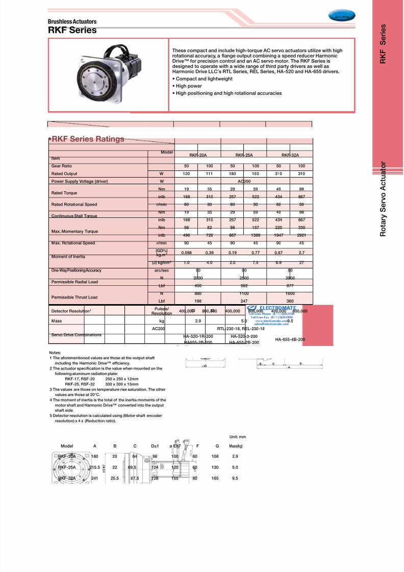
Brushless Actuators
These compact and include high-torque AC servo actuators utilize with highrotational accuracy, a ange output combining a speed reducer HarmonicDrive™ for precision control and an AC servo motor. The RKF Series isdesigned to operate with a wide range of third party drivers as well asHarmonic Drive LLC’s RTL Series, REL Series, HA-520 and HA-655 drivers.
• Compact and lightweight
• High power
• High positioning and high rotational accuracies
•RKF Series Ratings
RKF Series
Actuators
Model
ItemRKF-20A RKF-25A RKF-32A
Gear Ratio 50 100 50 100 50 100
Rated Output W 120 111 180 190 310 310
Power Supply Voltage (driver) W AC200
Rated TorqueNm 19 35 29 59 49 98
inlb 168 310 257 522 434 867
Rated Rotational Speed r/min 60 30 60 30 60 30
Continuous Stall TorqueNm 19 35 29 59 49 98
inlb 168 310 257 522 434 867
Max. Momentary TorqueNm 56 82 98 157 220 330
inlb 496 726 867 1389 1947 2921
Max. Rotational Speed r/min 90 45 90 45 90 45
Moment of Inertia
(GD2 / 4 )kg.m2 0.098 0.39 0.19 0.77 0.67 2.7
(J) kgfcm2 1.0 4.0 2.0 7.9 6.9 27
One-Way Positioning Accuracy arc/sec 90 90 90
Permissible Radial LoadN 2000 2500 3900
Lbf 450 562 877
Permissible Thrust LoadN 880 1100 1600
Lbf 198 247 360
Detector Resolution1 Pulses/ Revolution
400,000 800,000 400,000 800,000 400,000 800,000
Mass kg 2.9 5.0 9.5
Servo Drive Combinations
AC200 RTL-230-18, REL-230-18
HA-520-1R-200
HA655-2B-200
HA-520-3-200
HA-655-2B-200HA-655-4B-200
Notes:
1 The aforementioned values are those at the output shaft
including the Harmonic Drive™ efciency.
2 The actuator specication is the value when mounted on the
following aluminum radiation plate:
RKF-17, RSF-20 250 x 250 x 12mm
RKF-25, RSF-32 300 x 300 x 15mm
3 The values are those on temperature rise saturation. The other
values are those at 20°C.
4 The moment of inertia is the total of the inertia moments of themotor shaft and Harmonic Drive™ converted into the output
shaft side.
5 Detector resolution is calculated using (Motor shaft encoder
resolution) x 4 x (Reduction ratio).
Model A B C D±1 ø Eh7 F G Mass(kg)
RKF-20A 180 20 64 96 100 60 108 2.9
RKF-25A 215.5 22 69.5 124 120 60 130 5.0
RKF-32A 241 25.5 87.5 128 155 80 165 9.5
Unit: mm

8/3/2019 Harmonic Drive 2010 Catalog
http://slidepdf.com/reader/full/harmonic-drive-2010-catalog 16/56
Actuators
Model
Item
RH-5A RH-8D RH-11D RH-14D
8802 5502 4402 6006 3006 6001 3001 6002 3002
Rated Output W 1.5 1.7 1.4 8.6 6.2 13.6 12.3 20.3 18.5
Rated Voltage V 12 12 12 24 24 24 24 24 24
Maximum Momentary TorqueN•m 0.39 0.59 0.69 2.7 3.5 4.9 7.8 14 20
in-lb 3.45 5.22 6.11 23.9 31.0 43.4 60.0 123.9 177.0
Maximum Continuous StallTorque
N•m 0.24 0.39 0.43 1.5 2.3 2.5 4.4 5.4 7.8
in-lb 2.12 3.45 3.81 13.3 20.4 22.1 38.9 47.8 69.0
Rated TorqueN•m 0.16 0.29 0.29 1.4 2 2.2 3.9 3.2 5.9
in-lb 1.42 2.57 2.57 12.4 17.7 19.5 34.5 28.3 52.5
Maximum Positioning Speed r/min 180 110 90 100 50 100 50 100 50
Rated Positioning Speed r/min 88 55 44 60 30 60 30 60 30
Maximum Momentary Current A 0.83 0.78 0.77 1.6 1.1 2.4 2.1 5.4 4.1
Rated Current A 0.5 0.5 0.5 1.0 0.8 1.3 1.3 1.8 1.8
Torque ConstantN•m/A 0.69 1.11 1.38 2.1 4.2 2.46 4.91 2.92 5.76
in-lb/A 6.1 9.8 12.2 18.6 37.2 21.7 43.5 25.8 51
Moment of Inertiakg•m2 6.3x10⁻⁴ 16x10-4 25x10-4 37x10-4 150x10-4 110x10-4 430x10-4 210x10-4 810x10-4
kgf•cm•s2 0.007 0.016 0.026 0.04 0.15 0.11 0.44 0.21 0.83
One-Way Positioning Accuracy arc/sec 290 290 290 150 150 120 120 120 120
Permissible Thrust LoadN 29 29 29 98 98 196 196 392 392
lb 7 7 7 22 22 44 44 88 88
Reduction Ratio 50 80 100 50 100 50 100 50 100
Weight kg 0.09 0.09 0.09 0.3 0.3 0.5 0.5 0.77 0.77
Environmental ConditionsTime constant: Continuous • Protection: Totally closed, self-cooling • Ambient temperature: 0 to 40˚C
Ambient humidity: 35 to 80% RH (no condensation permitted)
Driver In Combination HA-360-1A HS-360-1B HS-360-1C HS-360-1D
This RH Mini Series is a DC servo actuator incorporating Harmonic Drive™precision gears, a high performance brush DC servo motor and an incrementalencoder.
• High Torque
• Precise Positional Accuracy
• Compact Design
DC Servo Actuators
RH Mini Series
•RH Series Ratings
Drawings (DXF) can be downloaded from our home page. URL: http://HarmonicDrive.net
Model of Actuator øA øB C D
RH-5A 20 5 11 78
RH-8D 33 8 21.8 107.2
RH-11D 40 10 25 125.2
RH-14D 50 12 28 148
Unit: mm
R o t a r y S e r v
o A c t u a t o r
R H
S e r i e s

8/3/2019 Harmonic Drive 2010 Catalog
http://slidepdf.com/reader/full/harmonic-drive-2010-catalog 17/56
Direct DriveMotor
KDU-13SA KDU-13WA
A 80 -4
•KDU Series Ratings
The KDU Series are Direct Drive Motors which acheive 10 arc-sec positioning
accuracy as well as ±0.5 arc-sec Repeatability with a resolution of 0.16 arc-sec.
Also, the KDU has a large Hollow Shaft design which allow cables, shafts or lasers
to pass through the axis of rotation.
— Exceptional positional accuracy
— Exceptional repeatability
— Ultra high resolution
Model
ItemKDU-13SA KDU-13WA
Maximum Torque2 Nm 7.0 15.0
In.lb 62.0 132.8
Max. Positioning Speed r/min 180 160
Torque Constant Nm/A 3.1 6.5
In.lb/A 27.4 57.5
Input Power Supply Voltage V AC 100
Moment of Inertia GD2 / 4 kg.m2 0.0047 0.0065
Moment of StiffnessNm/rad 2.4 x 10⁵
Inlb/rad 2.12 x 10⁴
Motor Position Sensor Pulse/revIncremental encoder:
23 bits (8,388,608)
Repeatability3 arc sec ± 0.5
Absolute Positioning Accuracy3 104
Mass kg 4.0 5.0
Mounting Direction Output shaft to face upward
Combined Driver HA-720-5-100
1 The table above shows output values of output shaft.
2 The values in the table above are obtained when connected to HA-720 servo driver.
3 The repeatability and absolute repeatability are the values measured in an environment of 23 ±0.3°C in temperature, 50% RH in humidity andwith output shaft facing upward in mounting direction. Please operate the product after checking “Precautions for maintaining accuracy” below.
4 Value with angular position error compensation by HA-720.
KDU SeriesDirect Drive Motor

8/3/2019 Harmonic Drive 2010 Catalog
http://slidepdf.com/reader/full/harmonic-drive-2010-catalog 18/56
Actuators
ItemModel
DriveStroke(mm)
MaximumDriving Force (N)
Resolution(µm)
MaximumSpeed (mm/s)
RepeatabilityOutside
Dimensions(mm)
Total length(mm)
LBC-25A-5D6K Brushless Motor 50 6000 0.32 20 ±5µm orless/50mm
strokeφ136 353
LBC-25A-5D12K Brushless Motor 50 12000 0.16 10
Precision Linear Actuators
LBC Series
•LBC Series Ratings
The precision lead screw provides positioning accuracy in the micron range with sub-micron repeatability. The actuator is capable of thrust forces up to 12,000 N.
This product is useful for precise positioning of heavy loads or applications where highforce is required such as molding equipment or precision presses.
L i n e a r A c t u
a t o r
L A S e r i e s
8/3/2019 Harmonic Drive 2010 Catalog
http://slidepdf.com/reader/full/harmonic-drive-2010-catalog 19/56Drawings (DXF) can be downloaded from our home page. URL: http://www.HarmonicDrive.net
Unit: mm
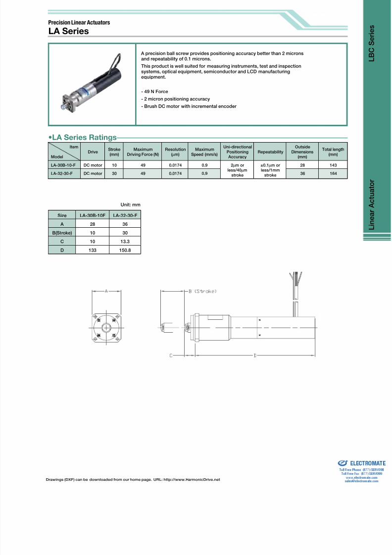
Size LA-30B-10F LA-32-30-F
A 28 36
B(Stroke) 10 30
C 10 13.3
D 133 150.8
A precision ball screw provides positioning accuracy better than 2 micronsand repeatability of 0.1 microns.
This product is well suited for measuring instruments, test and inspectionsystems, optical equipment, semiconductor and LCD manufacturingequipment.
- 49 N Force
- 2 micron positioning accuracy
- Brush DC motor with incremental encoder
Precision Linear Actuators
LA Series
Item
ModelDrive
Stroke(mm)
MaximumDriving Force (N)
Resolution(µm)
MaximumSpeed (mm/s)
Uni-directionalPositioning Accuracy
RepeatabilityOutside
Dimensions(mm)
Total length(mm)
LA-30B-10-F DC motor 10 49 0.0174 0.9 2µm orless/40µm
stroke
±0.1µm orless/1mm
stroke
28 143
LA-32-30-F DC motor 30 49 0.0174 0.9 36 164
•LA Series Ratings

8/3/2019 Harmonic Drive 2010 Catalog
http://slidepdf.com/reader/full/harmonic-drive-2010-catalog 20/56
Unit: mm
Model
SymbolLAH-46-1002-F LAH-46-3002-F
A 47 47
B(Stroke) 10 30
C 16 16
D 169 188
LAH Series
Actuators
Precision Linear Actuators
Item
ModelDrive
Stroke(mm)
MaximumDriving Force (N)
Resolution(µm)
MaximumSpeed(mm/s)
Uni-directionalPositioning Accuracy
RepeatabilityOutside
Dimensions(mm)
Totallength(mm)
LAH-46-1002-F DC motor 10 392 0.069 3.7 4µm orless/.02mm
stroke
±0.5µm orless/1mm
stroke
47 185
LAH-46-3002-F DC motor 30 392 0.069 3.7 47 204
LAH-80-5020-F-PAStepping
motor50 3000 2 10
4µm orless/2mm
stroke
±1µm orless/1mm
stroke
85 320
•LAH Series Ratings
A precision ball screw provides positioning accuracy better than 4 micronsand repeatability of 1 micron.
This product is well suited for measuring instruments, test and inspectionsystems, optical equipment, semiconductor and LCD manufacturingequipment.
- 392 to 3000 N Force
- 4 micron positioning accuracy
LAH-80
LAH-46 LAH-80
L i n e a r A c t u
a t o r
L A S e r i e s

8/3/2019 Harmonic Drive 2010 Catalog
http://slidepdf.com/reader/full/harmonic-drive-2010-catalog 21/56
Item
ModelDrive
Stroke(mm)
TableSize (mm)
Load(kg)
Resolution (µm)Maximum
Speed(mm/s)
Uni-directionalPositioning Accuracy
RepeatabilityTotal Length
(mm)
LNP-4040-13Stepping Motor
13 40x40 100.04 0.02
1.8 1.5 6.0µm or less ±0.5µm or less143.3
DC servomotor 0.056 0.028 172.5
LNP-5050-13Stepping Motor
13 50x50 100.04 0.02
1.8 1.5 6.0µm or less ±0.5µm or less153.3
DC servomotor 0.056 0.028 182.5
LNP-6060-15Stepping Motor
15 60x60 100.04 0.02
1.8 1.5 6.0µm or less ±0.5µm or less163.3
DC servomotor 0.056 0.028 192.5
LNP-7070-15Stepping Motor
15 70x70 100.04 0.02
1.8 1.5 6.0µm or less ±0.5µm or less173.3
DC servomotor 0.056 0.028 202.5
•LNP Series Ratings
Unit: mm
Model LNP-4040-13 LNP-5050-13 LNP-6060-15 LNP-770-15
Motor
Symbol
Step DC Step DC Step DC Step DC
A 103.3 132.5 103.3 132.5 103.3 132.5 103.3 132.5
B 143.3 172.5 153.3 182.5 163.6 192.5 173.3 202.5
C 40 40 50 50 60 60 70 70
D 58.1 58.1 68.5 68.5 78.5 78.5 88.5 88.5
E 20 20 20 20 20 20 20 20
A precision lead screw provides positioning accuracy better than 6 microns andrepeatability of 0.5 microns. The LNP also incorporates a high precision linear stagewhich enables direct mounting of a load to the actuator. Actuators can be combined fortwo or three axis congurations.
This product is well suited for measuring instruments, test and inspection systems,optical equipment, semiconductor and LCD manufacturing equipment.
- 10 Kg load capacity
- 6 micron positioning accuracy
- Available with Brush DC motor with incremental encoder or stepper motor
Precision Linear Actuators
LNP Series
8/3/2019 Harmonic Drive 2010 Catalog
http://slidepdf.com/reader/full/harmonic-drive-2010-catalog 22/56
Optical Scanners
ItemModel
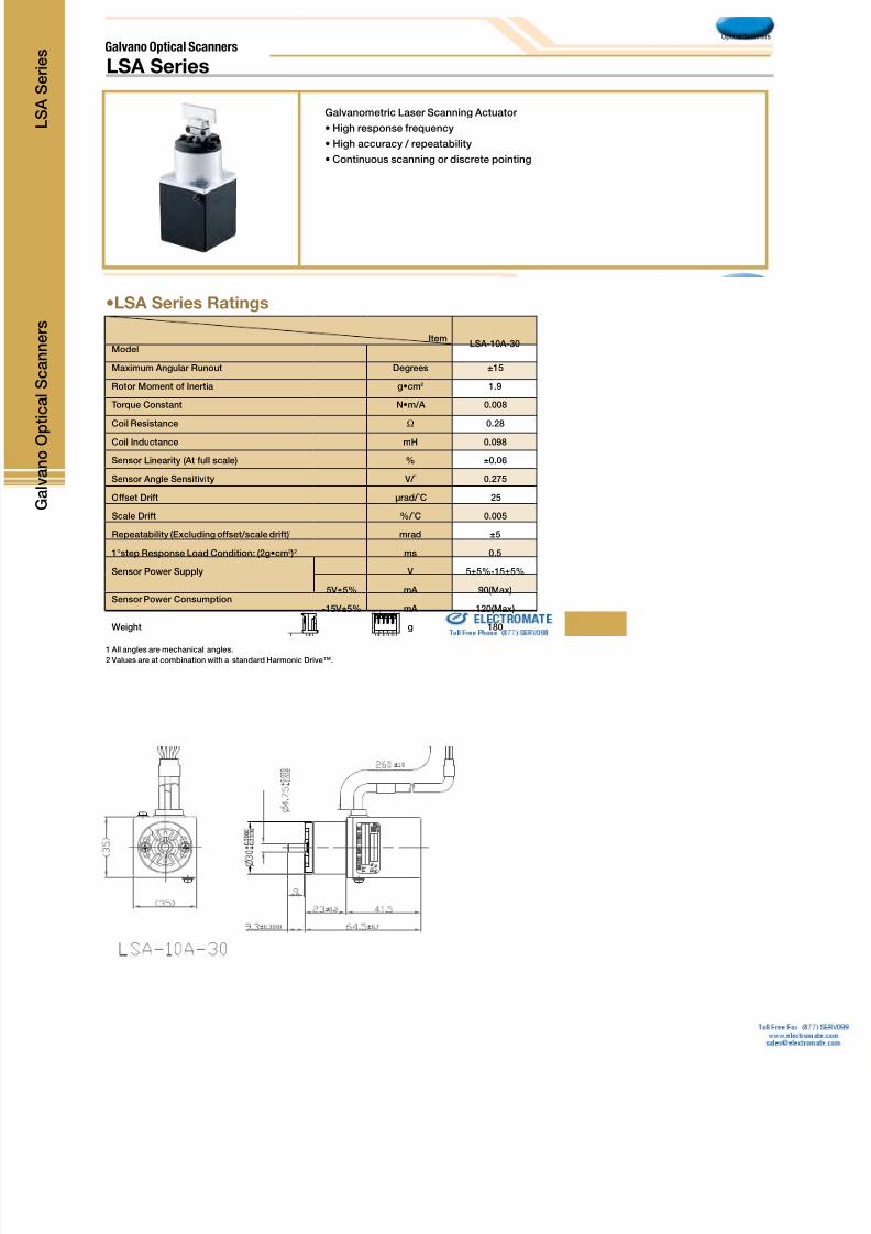
LSA-10A-30
Maximum Angular Runout Degrees ±15
Rotor Moment of Inertia g•cm2 1.9
Torque Constant N•m/A 0.008
Coil Resistance Ω 0.28
Coil Inductance mH 0.098
Sensor Linearity (At full scale) % ±0.06
Sensor Angle Sensitivity V/˚ 0.275
Offset Drift µrad/˚C 25
Scale Drift %/˚C 0.005
Repeatability (Excluding offset/scale drift)1 mrad ±5
1°step Response Load Condition: (2g•cm2 )2 ms 0.5
Sensor Power Supply V 5±5%-15±5%
Sensor Power Consumption5V±5% mA 90(Max)
-15V±5% mA 120(Max)
Weight g 180
•LSA Series Ratings
1 All angles are mechanical angles.2 Values are at combination with a standard Harmonic Drive™.
Galvanometric Laser Scanning Actuator
• High response frequency
• High accuracy / repeatability
• Continuous scanning or discrete pointing
Galvano Optical Scanners
LSA Series
G a l v a n o O p
t i c a l S c a n n e r s
L S A S e r i e s

8/3/2019 Harmonic Drive 2010 Catalog
http://slidepdf.com/reader/full/harmonic-drive-2010-catalog 23/56
Senser
ModelItem
MES-6- PC
Number of Pulses
ME -9- PC
Shaft Shape Number of Pulses•S: Single Shaft •H: Hollow shaft
Power Supply DC5V±10% DC5V±10%
Current Consumption 30mA or less (under no load) 40mA or less (under no load)
Detection System Incremental Incremental
Number of Output Pulses (Standard)[Number of Pulses/Number of Revolutions]
100 200 300 360 300 500 1000
Output Phases A, B and Z phases A, B and Z phases
Output Mode Square wave, open collector output Square wave, open collector output
Maximum Response Frequency(Number of Response Pulses)
100kHz 100kHz
Output Phase DifferenceDifference between A and B Phases 90˚±45˚
(T/4±T/8), Z Phase±T/2 (See output waveformdiagram.)
Difference between A and B Phases 90˚±45˚(T/4±T/8), Z Phase±T/2 (See output waveform
diagram.)
Permissible Maximum Positioning Speed(Mechanical)
600min-1 600min-1
Operating Temperature and Humidity0˚C~60˚C RH 35%~90%
No condensation permitted0˚C~60˚C RH 35%~90%
No condensation permitted
Storage Ambient Temperature -20˚C~80˚C -20˚C~80˚C
Weight 5g 10g
•Micro Encoder Series Ratings
06 SERIES 09 SERIES
Output Waveform Appearance Output Waveform Appearance
Accessory: Lock nut
Hollow Shaft Type Shaft Typ
Micro Encoder Series
This micro encoder series represents a combination of high resolution and theworld’s smallest form factor. It features two encoder channels with an index pulse.

8/3/2019 Harmonic Drive 2010 Catalog
http://slidepdf.com/reader/full/harmonic-drive-2010-catalog 24/56
Servo Drives
•Servo Driver Specications
DEP SeriesDCJ Series RTL & REL SeriesDDP Series
•DC Digital Servo Drive DCJ Series
•AC Digital Servo Drive RTL Series
•DC Digital Servo Drive DDP Series
•DC Digital Servo Drive DEP Series
•AC Digital Servo Drive REL Series
MODEL Vdc lc lp Control Modes Control Interface Encoder
DCJ-055-09 20-55 3 9
Indexter, Point-to-Point, PVT
Camming, Gearing, Position,
Velocity, Torque
CANopen/DeviceNet
ASCII and discrete I/O,
Stepper commands
± 10V position/velocity/torque command
PWM velocity/torque command
Master encoder (Gearing/Camming)
14 Wire Standard Incremental
Encoder Type
DCJ-055-18 20-55 6 18
DCJ-090-03 20-90 1 3
DCJ-090-09 20-90 3 9
DCJ-090-12 20-91 6 12
MODEL Vdc lc lp Control Modes Control Interface Encoder
RTL-230-18 100-240 6 18
Indexter, Point-to-Point, PVT
Camming, Gearing, Position,
Velocity, Torque
CANopen/DeviceNet
ASCII and discrete I/O,
Stepper commands
± 10V position/velocity/torque command
PWM velocity/torque command
Master encoder (Gearing/Camming)
14 Wire Standard IncrementalEncoder Type
RTL-230-36 100-240 12 36
RTL-230-40 100-240 20 40
MODEL Vdc lc lp Control Modes Control Interface Encoder
DDP-090-09 90 3 9
Indexter, Point-to-Point, PVT
Camming, Gearing, Position,
Velocity, Torque
CANopen/DeviceNet
ASCII and discrete I/O,
Stepper commands
± 10V position/velocity/torque command
PWM velocity/torque command
Master encoder (Gearing/Camming)
14 Wire Standard IncrementalEncoder Type
DDP-090-18 90 6 18
DDP-090-36 90 12 36
DDP-055-18 55 6 18
DDP-180-09 180 3 9
DDP-180-18 180 6 18
MODEL Vdc lc lp Control Modes Control Interface Encoder
DEP-090-09 90 3 9
Indexter, Point-to-Point, PVT
Camming, Gearing, Position,
Velocity, Torque
CANopen over EtherCAT (CoE)
ASCII and discrete I/O
± 10V position/velocity/torque command
Master encoder (Gearing/Camming)
14 Wire Standard IncrementalEncoder Type
DEP-090-18 90 6 18
DEP-090-36 90 12 36
DEP-055-18 55 6 18
DEP-180-09 180 3 9
DEP-180-18 180 6 18
DEP-090-09 90 3 9
4 Wire Serial CommunicationIncremental Encoder
DEP-090-18 90 6 18
DEP-090-36 90 12 36
DEP-090-09 90 3 9
HD Absolute Encoder A TypeDEP-090-18 90 6 18
DEP-090-36 90 12 36
MODEL Vdc lc lp Control Modes Control Interface Encoder
REL-230-18 100-240 6 18
Indexter, Point-to-Point, PVT
Camming, Gearing, Position,
Velocity, Torque
CANopen over EtherCAT (CoE)
ASCII and discrete I/O,
Stepper commands
± 10V position/velocity/torque command
PWM velocity/torque command
Master encoder (Gearing/Camming)
14 Wire Standard Incremental
Encoder TypeREL-230-36 100-240 12 36
REL-230-18 100-240 6 18
4 Wire Serial Communication
Incremental EncoderREL-230-36 100-240 12 36
REL-230-18 100-240 6 18
HD Absolute Encoder S TypeREL-230-36 100-240 12 36
REL-230-18 100-240 6 18
HD Absolute Encoder A TypeREL-230-36 100-240 12 36
REL-230-40 100-240 20 40
Servo Drivers
H a r m o n i c D
r i v e ™
S e r v o D r i v e r s

8/3/2019 Harmonic Drive 2010 Catalog
http://slidepdf.com/reader/full/harmonic-drive-2010-catalog 25/56
Servo Drives
•DC Digital Servo Drive DCJ Series
MODEL Vdc lc lp Supply Voltage Combination Actuator
DCJ-055-09 20-55 3 9
DC24V
FHA-8C-30 / 50 / 100-US200-E, RSF-8B-30 / 50 / 100-F100-24B,
RSF-5A-30 / 50 / 100-US050, RSF-3B-30 / 50 / 100-US020
DCJ-055-18 20-55 6 18 FHA-11C-30 / 50 / 100-US200-E
DCJ-090-03 20-90 1 3 –
DCJ-090-09 20-90 3 9 –
DCJ-090-12 20-91 6 12 –
•DC Digital Servo Drive DDP SeriesMODEL Vdc lc lp Supply Voltage Combination Actuator
DDP-090-09 90 3 9
DC24V
FHA-8C-30 / 50 / 100-US200-E, RSF-8B-30 / 50 / 100-F100-24B,
RSF-5A-30 / 50 / 100-US050, RSF-3B-30 / 50 / 100-US020
DDP-090-18 90 6 18 FHA-11C-30 / 50 / 100-US200-E
DDP-090-36 90 12 36FHA-14C-30 / 50 / 100-US200-E, FHA-17C50* / 100 / 160-US250-E-SP,
RSF-14B-30 / 50 / 100-F100-24B, RSF-11B-30 / 50 / 100-F100-24B
DDP-055-18 55 6 18 –
DDP-180-09 180 3 9 –
DDP-180-18 180 6 18 –
•DC Digital Servo Drive DEP Series
MODEL Vdc lc lp Supply Voltage Combination Actuator
DEP-090-09 90 3 9
DC24V
FHA-8C-30 / 50 / 100-US200-E, RSF-8B-30 / 50 / 100-F100-24B,
RSF-5A-30 / 50 / 100-US050, RSF-3B-30 / 50 / 100-US020
DEP-090-18 90 6 18 FHA-11C-30 / 50 / 100-US200-E
DEP-090-36 90 12 36
FHA-14C-30 / 50 / 100-US200-E, FHA-17C50* / 100* / 160-US250-E-SP,
RSF-14B-30 / 50 / 100-F100-24B, RSF-11B-30 / 50 / 100-F100-24B
DEP-090-09 90 3 9 FHA-8C-30 / 50 / 100-US200-E
DEP-90-18 90 6 18 FHA-11C-30 / 50 / 100-US200-E
DEP-90-36 90 12 36 FHA-14C-30 / 50 / 100-US200-E
DEP-090-09 90 3 9 FHA-8C-30 / 50 / 100-XXXX
DEP-90-18 90 6 18 FHA-11C-30 / 50 / 100-XXXX
DEP-90-36 90 12 36 FHA-14C-30 / 50 / 100-XXXX
DEP-055-18 55 6 18 –
DEP-180-09 180 3 9 –
DEP-180-18 180 6 18 –
MODEL Vdc lc lp Supply Voltage Combination Actuator
REL-230-18 100-240 6 18
AC100/200VFHA-8C-30 / 50 / 100-US200, FHA-11C-30 / 50 / 100-US200,
FHA-14C-30 / 50 / 100-US200
AC100VFHA-17C-50 / 100 / 160-US250-A, FHA-25C-100 / 160-US250-A,
FHA-32C-160-US250-A
AC200VFHA-17C-50 / 100 / 160-US250, FHA-25C-50 / 100 / 160-US250,
FHA-32C-50 / 100 / 160-US250, FHA-40C-100 / 160-US250
REL-230-36 100-240 12 36 AC100V FHA-25C-50-US250-A, FHA-32C-50 / 100-US250-A
AC200V FHA-40C-50-US250
REL-230-18 100-240 6 18
AC100/200VFHA-8C-30 / 50 / 100-E200, FHA-11C-30 / 50 / 100-E200,
FHA-14C-30 / 50 / 100-E200
AC100VFHA-17C-50 / 100 / 160-E250-A, FHA-25C-100 / 160-E250-A,
FHA-32C-160-E250-A
AC200VFHA-17C-50 / 100 / 160-E250, FHA-25C-50 / 100 / 160-E250,
FHA-32C-50 / 100 / 160-E250, FHA-40C-100 / 160-E250
REL-230-36 100-240 12 36 AC100V FHA-25C-50-E250-A, FHA-32C-50 / 100-E250-A
AC200V FHA-40C-50-E250
REL-230-18 100-240 6 18
AC100VFHA-17C-50 / 100 / 160-S248-A, FHA-25C-100 / 160-S248-A,
FHA-32C-160-ES248-A
AC200VFHA-17C-50 / 100 / 160-S248, FHA-25C-50 / 100 / 160-S248,
FHA-32C-50 / 100 / 160-ES248, FHA-40C-100 / 160-ES248
REL-230-36 100-240 12 36 AC100V FHA-25C-50-S248-A, FHA-32C-50 / 100-ES248-A
AC200V FHA-40C-50-S248
REL-230-18 100-240 6 18
AC200V
SHA-25-51 /81 / 101 / 121 / 161, SHA-32-161,
REL-230-36 100-240 12 36 SHA-32-51 / 81 / 101 / 121, SHA-40-121 / 161,
REL-230-40 100-240 20 40 SHA-40-51 /81 /101
•AC Digital Servo Drive RTL Series
MODEL Vdc lc lp Supply Voltage Combination Actuator
RTL-230-18 100-240 6 18
AC100/200VFHA-8C-30 / 50 / 100-US200, FHA-11C-30 / 50 / 100-US200,
FHA-14C-30 / 50 / 100-US200
AC100VFHA-17C-50 / 100 / 160-US250-A, FHA-25C-100 / 160-US250-A,
FHA-32C-160-US250-A
AC200VFHA-17C-50 / 100 / 160-US250, FHA-25C-100 / 160-US250,
FHA-32C-160-US250, FHA-40C-100 / 160-US250
RTL-230-36 100-240 12 36 AC100V FHA-25C-50-US250-A, FHA-32C-50 / 100-US250-A
AC200V FHA-40C-50-US250
RTL-230-40 100-240 20 40 AC200V –
•AC Digital Servo Drive REL Series
Combinations with Driver
•Combinations with Servo Drive and Actuator
8/3/2019 Harmonic Drive 2010 Catalog
http://slidepdf.com/reader/full/harmonic-drive-2010-catalog 26/56
Servo Drives
•Servo Driver Specications
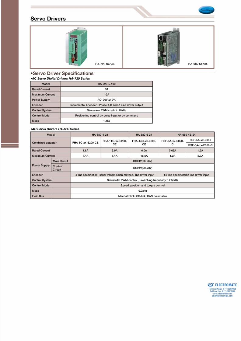
Model HA-680-4-24 HA-680-6-24 HA-680-4B-24
Combined actuator FHA-8C-xx-E200-CEFHA-11C-xx-E200-
CEFHA-14C-xx-E200-
CERSF-3A-xx-E020-
C
RSF-5A-xx-E050
RSF-5A-xx-E050-B
Rated Current 1.8A 3.9A 6.0A 0.65A 1.2A
Maximum Current 3.4A 8.4A 16.5A 1.2A 2.3A
Power Supply
Main Circuit DC24V(20-28V)
ControlCircuit
DC24V(20-28V)
Encoder 4-line speciction, serial transmission method, line driver input 14-line specication line driver input
Control System Sinusoidal PWM control , switching frequency: 12.5 kHz
Control Mode Speed, position and torque control
Mass 0.23kg
Field Bus Mechatrolink, CC-link, CAN Selectable
•AC Servo Drivers HA-680 Series
HA-720 Series HA-680 Series
Model HA-720-5-100
Rated Current 5A
Maximum Current 10A
Power Supply AC100V ±10%
Encoder Incremental Encoder: Phase A,B and Z Line driver output
Control System Sine wave PWM control: 20kHz
Control Mode Positioning control by pulse input or by command
Mass 1.4kg
•AC Servo Digital Drivers HA-720 Series
Servo Drivers

8/3/2019 Harmonic Drive 2010 Catalog
http://slidepdf.com/reader/full/harmonic-drive-2010-catalog 27/56
Servo Drives
ModelIncremental
HA-655-1-100HA-655-1B-100
HA-655-2-200HA-655-2B-200
HA-655-4-200HA-655-4B-200
HA-655-1-100HA-655-1B-100
HA-655-2-100HA-655-2B-100
HA-655-4-100HA-655-4B-100
Absolute — HA-655-2A-200 HA-655-4A-200 — HA-655-2A-100 HA-655-4A-100
Rated Current 1.0A 2.4A 1.4A 1.0A 2.4A 4A
Maximum Current 3.2A 7.3A 18.0A 3.2A 7.3A 18.0A
Power Supply
Main Circuit AC200~240V (Single phase/3 phases) +10~-15% AC100~115V (Single phase) +10~-15%
Control Circuit AC100~115V (Single phase) or
AC200~240V (Single phase) +10~-15% AC100~115V (Single phase) +10~-15%
Control System Sine wave PWM control
Control Mode Position control, speed control
Weight 1.5kg 1.5kg 1.7kg 1.5kg 1.5kg 1.7kg
ModelIncremental HA-675-1-200 HA-675-2-200 HA-675-4-200 HA-675-1-100 HA-675-2-100 HA-675-4-100
Absolute — HA-675-2A-200 HA-675-4A-200 — HA-675-2A-100 HA-675-4A-100
Rated Current 1.0A 2.4A 4.0A 1.0A 2.4A 4.0A
Maximum Current 3.2A 7.3A 18.0A 3.2A 7.3A 18.0A
Power Supply
Main Circuit AC200~240V (single phase/3 phases) +10~15% AC100~115V (Single phase) +10~-15%
Control Circuit AC100~115V (Single phase) or AC200~240V (Single
phase) +10~-15% AC100~115V (Single phase) +10~-15%
Control System Sine wave PWM controlWeight 1.5kg 1.5kg 1.7kg 1.5kg 1.5kg 1.7kg
•Servo Driver Specications•AC Servo Digital Drivers HA-655 Series
•AC Servo 1 Axis Controller Drivers HA-675 Series
HA-655 SeriesHA-675 Series HS-360 Series
Model HS-360-1A HS-360-1B HS-360-1C HS-360-1D HS-360-3
Rated Current 1.0A 1.4A 3.2A
Maximum Current 1.0A 2.6A 3.7A 4.2A 10A
Power Source Voltage AC100V (Single Phase)±10%
Encoder Incremental Encoder (A, B and Z phase output), line driver system
Control System PWM control (control device: IPM), switching frequency: 12.5kHz
Control Mode Position control by pulse train output
Weight 0.8kg 0.8kg 0.8kg 0.8kg 1.1kg
Environmental Conditions
Operating temperature: 0 to 50˚C • Storage temperature: -20 to +85˚C • Operating and storage humidity: 95% RH orlower (No condensation permitted).
Vibration resistance: 4.9m/s 2 (frequency: 0 to 55Hz) • Shock resistance: 98 m/S2. No metal shaves and chips, no dust, nooil mist and no corrosive gas.
Structure/Mounting Direction Totally enclosed, self cooling type/Wall-mount orientation
•DC Servo Drivers HS-360 Series
•Common Specifcation to Servo Driver Series
Servo Drivers

8/3/2019 Harmonic Drive 2010 Catalog
http://slidepdf.com/reader/full/harmonic-drive-2010-catalog 28/56
Servo Drives
Series Model No. Servo Drive
LSA All models PSM-130
Series Model No. Servo Drive
LA*30 HS-360-1A-100
32 HS-360-1A-100
LAH* 46HS-360-1A-100
80
LBC 25HA-655-2B-200
HA-675-2B-200
LNP*HS-360-1A-100
* RH,LA,LAH,LNP series actuators will require servo drive
encoder when used in conjunction with a HS-360 driver.
Type Motor TypeBus Voltage
Encoder Type Encoder Output FormServo Drive
V HA-360 HA-655 HA-675 HA-680 US OEM
RSF-3B Brushless DC DC24 200 Line Incremental
8 wire open collector x x x x o
14 wire line driver
(with relay cable option)x x x o o
RSF-5A Brushless DC DC24 500 Line Incremental
8 wire open collector x x x x o
14 wire line driver
(with relay cable option)x x x o o
RSF-8B, 11B, 14B Brushless DC DC24 1000 Line Incremental 14 wire line driver x x x o o
FHA-8C, 11C, 14C
Brushless DC DC24 2000 Line Incremental4 wire serial x o o x x
14 wire line driver x o o x o
Brushless DC AC100
AC2002000 Line Incremental
4 wire serial x o o x x
14 wire line driver x o o x o
FHA-17C, 25C, 32C Brushless DC AC100
AC200
2,500 Line Incremental4 wire serial x o o x x
14 wire line driver x 0 0 x 0
13bit Absolute 4 wire serial x o o x x
FHA-40C Brushless DC AC2002,500 Line Incremental
4 wire serial x o o x x
14 wire line driver x o o x o
13bit Absolute 4 wire serial x 0 0 x x
RH-5A Brush DC DC12200, 360, or 500 Line
Incremental
8 wire open collector o x x x o
14 wire line driver o x x x o
RH-8D, 11D, 14D Brush DC DC24200, 360, 500 or
1000 Line Incremental
8 wire open collector o x x x o
14 wire line driver o x x x o
Combinations with Driver
•Combinations with Actuator and Servo Drive
Rotary Actuators
Galvano Optical Scanner
Linear Actuators
H a r m o n i c D
r i v e ™
S e r v o D r i v e r s

8/3/2019 Harmonic Drive 2010 Catalog
http://slidepdf.com/reader/full/harmonic-drive-2010-catalog 29/56
Item
Model No.
Reduction
Ration
Rated Torque at2000rpm
Limit for
Repeated Peak
Torque
PermissibleMaximum
Momentary Torque
N•m In.lb N•m In.lb N•m In.lb
14
50 7.0 62 23 204 46 407
80 10 89 30 266 61 540
100 10 89 36 319 70 620
17
50 21 186 44 389 91 805
80 29 257 56 496 113 1000100 31 274 70 620 143 1266
120 31 274 70 620 112 991
20
50 33 292 73 646 127 1124
80 44 389 96 850 165 1460
100 52 460 107 947 191 1690
120 52 460 113 1000 191 1690
160 52 460 120 1062 191 1690
25
50 51 451 127 1124 242 2142
80 82 726 178 1575 332 2938
100 87 770 204 1805 369 3266
120 87 770 217 1920 395 3496
160 87 770 229 2027 408 3611
32
50 99 876 281 2487 497 4398
80 153 1354 395 3496 738 6531
100 178 1575 433 3832 841 7443
120 178 1575 459 4062 892 7894
160 178 1575 484 4283 892 7894
Item
Model No.
Reduction
Ration
Rated Torque at2000rpm
Limit for
Repeated Peak
Torque
PermissibleMaximum
Momentary Torque
N•m In.lb N•m In.lb N•m In.lb
40
50 178 1575 523 4629 892 7894
80 268 2372 675 5974 1270 11240
100 345 3053 738 6531 1400 12390
120 382 3381 802 7098 1530 13541
160 382 3381 841 7443 1530 13541
45
50 229 2027 650 5753 1235 1093080 407 3602 918 8124 1651 14611
100 459 4062 982 8691 2041 18063
120 523 4629 1070 9470 2288 20249
160 523 4629 1147 10151 2483 21975
50
80 484 4283 1223 10824 2418 21399
100 611 5407 1274 11275 2678 23700
120 688 6089 1404 12425 2678 23700
160 688 6089 1534 13576 3185 28187
58
80 714 6319 1924 17027 3185 28187
100 905 8009 2067 18293 4134 36586
120 969 8576 2236 19789 4329 38312
160 969 8576 2392 21169 4459 39462
65
80 969 8576 2743 24276 4836 42799
100 1236 10939 2990 26462 6175 54649
120 1236 10939 3263 28878 6175 54649
160 1236 10939 3419 30258 6175 54649
Model No
Symbol14 17 20 25 32 40 45 50 58 65
ø A 50 60 70 85 110 135 155 170 195 215
B 28.5 32.5 33.5 37 44 53 58.5 64 75.5 83
Speed reducer
Cup Type High Torque
CSG Series
• Compact and simple design
• High torque capacity
• High torsional stiffness
• Zero backlash
• High positioning accuracy
• Housed unit type is available (see p. 28)
• 30% higher torque than a CSF unit
L1 0
L i f e : 1 0 , 0 0 0 h
Drawings (DXF) can be downloaded from our home page. URL: http://www.HarmonicDrive.net
Comparison of Features. High Torque Harmonic Drive™ CSG Series vs. CSF Series
[When CSF is set to 100]
Permissible MaximumMomentary Torque
Average RatchetingTorque
Permissible PeakTorque
Rated
Torque
Life
(Hours)
•CSG Series Ratings
Unit: mm

8/3/2019 Harmonic Drive 2010 Catalog
http://slidepdf.com/reader/full/harmonic-drive-2010-catalog 30/56
Speed reducer
• Superior axial compactness
• Hollow through bore
• Excellent Repeatability
• Also available with extra large through bore
•CSD Series Ratings
CSD Series
Cup Type - Super Flat Type
L1 0
L i f e : 7 , 0 0 0 h
No
Symbol14 17 20 25 32 40 50
ø A h7 50 60 70 85 110 135 170
B 11 12.5 14 17 22 27 33
Unit: mm
Item
Model No.
ReductionRatio
Rated Torque at 2000 rpmLimit for Repeated
Peak TorquePermissible Maximum
Monetary Torque
N•m In.lb N•m In.lb N•m In.lb
1450 3.7 33 12 106 24 212
100 5.4 48 19 168 31 274
1750 11 97 23 204 48 425
100 16 142 37 327 55 487
20
50 17 150 39 345 69 611
100 28 248 57 504 76 673
160 28 248 64 566 76 673
25
50 27 239 69 611 127 1124
100 47 416 110 974 152 1345
160 47 416 123 1089 152 1345
32
50 53 469 151 1336 268 2372
100 96 850 233 2062 359 3177
160 96 850 261 2310 359 3177
40
50 96 850 281 2487 480 4248
100 185 1637 398 3522 694 6142
160 206 1823 453 4009 694 6142
50
50 172 1522 500 4425 1000 8850
100 329 2912 686 6071 1440 12744
160 370 3275 823 7284 1577 13956
H a r m o n i c D
r i v e ™
C o m p o n e n t S e t
C S D S e r i e s

8/3/2019 Harmonic Drive 2010 Catalog
http://slidepdf.com/reader/full/harmonic-drive-2010-catalog 31/56
Speed reducer
Cup Type
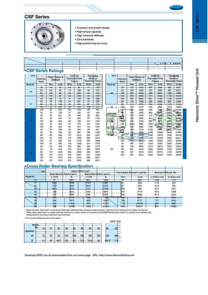
CSF Series
• Compact design
• High torque capacity
• High torsional stiffness
• Zero backlash
• High positioning accuracy
• Housed conguration is available (see p. 29)
L1 0
L i f e : 7 , 0 0 0 h
Drawings (DXF) can be downloaded from our home page. URL: http://www.HarmonicDrive.net
ModelNo
Symbol
8 11 14 17 20 25 32 40
øA 30 10 50 60 70 85 110 135
B 22.1 25.8 28.5 32.5 33.5 37 44 53
ModelNo
Symbol
45 50 58 65 80 90 100
øA 155 170 195 215 265 300 330
B 58.5 64 75.5 83 101 112.5 125
Unit: mm
Item
ModelNo.
Reduction
Ratio
Rated Torque at200rpm
Limit for RepeatedPeak Torque
PermissibleMaximum
Momentary Torque
N•m In.lb N•m In.lb N•m In.lb
45
50 176 1558 500 4425 950 8408
80 313 2770 706 6248 1270 11240
100 353 3124 755 6682 1570 13895
120 402 3558 823 7284 1760 15576
160 402 3558 882 7806 1910 16904
50
50 245 2168 715 6328 1430 12656
80 372 3292 941 8328 1860 16461
100 470 4160 980 8673 2060 18231
120 529 4682 1080 9558 2060 18231
160 529 4682 1180 10443 2450 21683
58
50 353 3124 1020 9027 1960 17346
80 549 4859 1480 13098 2450 21683
100 696 6160 1590 14072 3180 28143
120 745 6593 1720 15222 3330 29471
160 745 6593 1840 16284 3430 30356
65
50 490 4337 1420 12567 2830 25046
80 745 6593 2110 18674 3720 32922
100 951 8416 2300 20355 4750 42038
120 951 8416 2510 22214 4750 42038
160 951 8416 2630 23276 4750 42038
80
50 872 7717 2440 21594 4870 43100
80 1320 11682 3430 30356 6590 58322
100 1700 15045 4220 37347 7910 70004
120 1990 17612 4590 40622 7910 70004
160 1990 17612 4910 43454 7910 70004
90
50 1180 10443 3530 31241 6660 58941
80 1550 13718 3990 35312 7250 64163
100 2270 20090 5680 50268 9020 79827
120 2570 22745 6160 54516 9800 86730
160 2700 23895 6840 60534 11300 100005
100
50 1580 13983 4450 39383 8900 78765
80 2380 21063 6060 53631 11600 102660
100 2940 26019 7350 65048 14100 124785
120 3180 28143 7960 70446 15300 135405
160 3550 31418 9180 81243 15500 137175
Item
ModelNo.
Reduction
Ratio
Rated Torque at200rpm
Limit for RepeatedPeak Torque
PermissibleMaximum
Momentary Torque
N•m In.lb N•m In.lb N•m In.lb
8
30 0.9 8 1.8 16 3.3 29
50 1.8 16 3.3 29 6.6 58
100 2.4 21 4.8 42 9.0 80
11
30 2.2 19 4.5 40 8.5 75
50 3.5 31 8.3 73 17 150100 5.0 44 11 97 25 221
14
30 4.0 35 9.0 80 17 150
50 5.4 48 18 159 35 310
80 7.8 69 23 204 47 416
100 7.8 69 28 248 54 478
17
30 8.8 78 16 142 30 266
50 16 142 34 301 70 620
80 22 195 43 381 87 770
100 24 212 54 478 108 956
120 24 212 54 478 86 761
20
30 15 133 27 239 50 443
50 25 221 56 496 98 867
80 34 301 74 655 127 1124
100 40 354 82 726 147 1301
120 40 354 87 770 147 1301
160 40 354 92 814 147 1301
25
30 27 239 50 443 95 841
50 39 345 98 867 186 164680 63 558 137 1212 255 2257
100 67 593 157 1389 284 2513
120 67 593 167 1478 304 2690
160 67 593 176 1558 314 2779
32
30 54 478 100 885 200 1770
50 76 673 216 1912 382 3381
80 118 1044 304 2690 568 5027
100 137 1212 333 2947 647 5726
120 137 1212 353 3124 686 6071
160 137 1212 372 3292 686 6071
40
50 137 1212 402 3558 686 6071
80 206 1823 519 4593 980 8673
100 265 2345 568 5027 1080 9558
120 294 2602 617 5460 1180 10443
160 294 2602 647 5726 1180 10443
•CSF Series Ratings

8/3/2019 Harmonic Drive 2010 Catalog
http://slidepdf.com/reader/full/harmonic-drive-2010-catalog 32/56
Speed reducer
Drawings (DXF) can be downloaded from our home page. URL: http://www.HarmonicDrive.net
Silk Hat Type - High-Torque
SHG Series
• Hollow bore units available
• Zero backlash
• Excellent positioning accuracy
• Compact and simple design
• High torque capacity
• High torsional stiffness
• 30% higher torque rating than SHF series
L1 0
L i f e : 1 0 , 0 0 0 h
Model No
Symbol14 17 20 25 32 40 45 50 58 65
øA 50 60 70 85 110 135 155 170 195 215
B 28.5 32.5 33.5 37 44 53 58.5 64 75.5 83
Unit: mm
•SHG Series Ratings
10 0
10 0
10 0
10 0
10 0
130
130
130
130
15 0
40 60 80 100 120 140 160(% )
SHF SHGPermissible MaximumMomentary Torque
Average RatchetingTorque
Permissible PeakTorque
RatedTorque
Life(Hours)
[WhenSHF is set to 100]
•Comparison of Features. High Torque Harmonic Drive™ High Torque SHG Series
Item
Model No.
Reduction
Ration
Rated Torque at2000rpm
Permissible
Peak Torque
PermissibleMaximum
Momentary Torque
N•m In.lb N•m In.lb N•m In.lb
40
50 178 1575 523 4629 892 7894
80 268 2372 675 5974 1270 11240
100 345 3053 738 6531 1400 12390
120 382 3381 802 7098 1530 13541
160 382 3381 841 7443 1530 13541
45
50 229 2027 650 5753 1235 10930
80 407 3602 918 8124 1651 14611100 459 4062 982 8691 2041 18063
120 523 4629 1070 9470 2288 20249
160 523 4629 1147 10151 2483 21975
50
80 484 4283 1223 10824 2418 21399
100 611 5407 1274 11275 2678 23700
120 688 6089 1404 12425 2678 23700
160 688 6089 1534 13576 3185 28187
58
80 714 6319 1924 17027 3185 28187
100 905 8009 2067 18293 4134 36586
120 969 8576 2236 19789 4329 38312
160 969 8576 2392 21169 4459 39462
65
80 969 8576 2743 24276 4836 42799
100 1236 10939 2990 26462 6175 54649
120 1236 10939 3263 28878 6175 54649
160 1236 10939 3419 30258 6175 54649
Item
Model No.
Reduction
Ration
Rated Torque at2000rpm
Permissible
Peak Torque
PermissibleMaximum
Momentary Torque
N•m In.lb N•m In.lb N•m In.lb
14
50 7.0 62 23 204 46 407
80 10 89 30 266 61 540
100 10 89 36 319 70 620
17
50 21 186 44 389 91 805
80 29 257 56 496 113 1000
100 31 274 70 620 143 1266120 31 274 70 620 112 991
20
50 33 292 73 646 127 1124
80 44 389 96 850 165 1460
100 52 460 107 947 191 1690
120 52 460 113 1000 191 1690
160 52 460 120 1062 191 1690
25
50 51 451 127 1124 242 2142
80 82 726 178 1575 332 2938
100 87 770 204 1805 369 3266
120 87 770 217 1920 395 3496
160 87 770 229 2027 408 3611
32
50 99 876 281 2487 497 4398
80 153 1354 395 3496 738 6531
100 178 1575 433 3832 841 7443
120 178 1575 459 4062 892 7894
160 178 1575 484 4283 892 7894
H a r m o n i c D
r i v e ™
C o m p o n e n t S e t
S H G S e r i e s

8/3/2019 Harmonic Drive 2010 Catalog
http://slidepdf.com/reader/full/harmonic-drive-2010-catalog 33/56
Speed reducer
•SHF Series Ratings
• Hollow bore units available
• Compact and simple design
• Zero backlash
• High torque capacity
• High positioning accuracy
• High torsional stiffness
• Housed in is available (see p. 31))
Size
Symbol14 17 20 25 32 40 45 50 58
øA 50 60 70 85 110 135 155 170 195
B 28.5 32.5 33.5 37 44 53 58.5 64 75.5
Unit: mm
Item
Model
ReductionRatio
Rated Torqueat 2000rpm
PermissiblePeak Torque
PermissibleMaximum
Momentary Torque
N•m In.lb N•m In.lb N•m In.lb
14
30 4.0 35 9.0 80 17 150
50 5.4 48 18 159 35 310
80 7.8 69 23 204 47 416
100 7.8 69 28 248 54 478
17
30 8.8 78 16 142 30 266
50 16 142 34 301 70 620
80 22 195 43 381 87 770
100 24 212 54 478 110 974
120 24 212 54 478 86 761
20
30 15 133 27 239 50 443
50 25 221 56 496 98 867
80 34 301 74 655 127 1124
100 40 354 82 726 147 1301
120 40 354 87 770 147 1301
160 40 354 92 814 147 1301
25
30 27 239 50 443 95 841
50 39 345 98 867 86 1646
80 63 558 137 1212 255 2257
100 67 593 157 1389 284 2513
120 67 593 167 1478 304 2690
160 67 593 176 1558 314 2779
32
30 54 478 100 885 200 1770
50 76 673 216 1912 382 3381
80 118 1044 230 2036 568 5027
100 137 1212 333 2947 647 5726
120 137 1212 353 3124 686 6071
160 137 1212 372 3292 686 6071
Item
Model
Reduction Ratio
Rated Torqueat 2000rpm
Limit forRepeated Peak
Torque
PermissibleMaximum Mo-mentary Torque
N•m In.lb N•m In.lb N•m In.lb
40
50 137 1212 402 3558 686 6071
80 206 1823 519 4593 980 8673
100 265 2345 568 5027 1080 9558
120 294 2602 617 5460 1180 10443
160 294 2602 647 5726 1180 10443
45
50 176 1558 500 4425 950 8408
80 313 2770 706 6248 1270 11240
100 353 3124 755 6682 1570 13895
120 402 3558 823 7284 1760 15576
160 402 3558 882 7806 1910 16904
50
50 245 2168 715 6328 1430 12656
80 372 3292 941 8328 1860 16461
100 470 4160 980 8673 2060 18231
120 529 4682 1080 9558 2060 18231
160 529 4682 1180 10443 2450 21683
58
50 353 3124 020 9027 1960 17346
80 549 4859 1480 13098 2450 21683
100 696 6160 1590 14072 3180 28143
120 745 6593 1720 15222 3330 29471
160 745 6593 1840 16284 3430 30356
L1 0
L i f e : 7 , 0 0 0 h
Silk Hat Type
SHF Series

8/3/2019 Harmonic Drive 2010 Catalog
http://slidepdf.com/reader/full/harmonic-drive-2010-catalog 34/56
Speed reducer
• High torque capacity
• High torsional stiffness
• Compact and simple design
• Zero backlash
• High positioning accuracy
• 30% higher torque than a CSF unit
L1 0
L i f e : 1 0 , 0 0 0 h
Drawings (DXF) can be downloaded from our home page. URL: http://www.HarmonicDrive.net
ModelNo.
Symbol
14 17 20 25 32 40 45 50 58 65
øA 73 79 93 107 138 160 180 190 226 260
B 41 45 45.5 52 62 72.5 79.5 90 104.5 115
Unit: mm
• “Basic dynamic rated load” is a constant stationary radial load that achieves a basic dynamic rated life of the bearing of one million revolutions.
“Basic static rated load” is a static load that achieves a contact stress of a constant level (408kN/mm2) at the center of a contact zone between the
rolling element receiving a maximum load and track.
• The moment stiffnesses are mean values.
•Cross Roller Bearing Specication
Item
Model No.
Basic Rated LoadPermissible Moment Load Mc Moment Stiffness Km
Basic Dynamic Rated Load C Basic Stat ic Rated Load Co
x 102N lb x 102N lb N•m In.lb x 104N•m /rad In.lb /arc-min
14 47 1057 60.7 1365 41 363 4.38 113
17 52.9 1189 75.5 1697 64 566 7.75 200
20 57.8 1299 90.0 2023 91 805 12.8 330
25 96.0 2158 151 3394 156 1381 24.2 623
32 150 3372 250 5620 313 2770 53.9 1388
40 213 4788 365 8205 450 3983 91.0 2343
45 230 5170 426 9576 686 6071 141 3631
50 348 7823 602 13533 759 6717 171 4403
58 518 11645 904 20322 1180 10443 283 7287
65 556 12499 1030 23154 1860 16461 404 10403
•CSG Series Ratings
Item
Model No.
Reduction
Ration
Rated Torque at2000rpm
Limit for
Repeated Peak
Torque
PermissibleMaximum
Momentary Torque
N•m In.lb N•m In.lb N•m In.lb
14
50 7.0 62 23 204 46 407
80 10 89 30 266 61 540
100 10 89 36 319 70 620
17
50 21 186 44 389 91 805
80 29 257 56 496 113 1000
100 31 274 70 620 143 1266
120 31 274 70 620 112 991
20
50 33 292 73 646 127 1124
80 44 389 96 850 165 1460
100 52 460 107 947 191 1690
120 52 460 113 1000 191 1690
160 52 460 120 1062 191 1690
25
50 51 451 127 1124 242 2142
80 82 726 178 1575 332 2938
100 87 770 204 1805 369 3266
120 87 770 217 1920 395 3496
160 87 770 229 2027 408 3611
32
50 99 876 281 2487 497 4398
80 153 1354 395 3496 738 6531
100 178 1575 433 3832 841 7443
120 178 1575 459 4062 892 7894
160 178 1575 484 4283 892 7894
Item
Model No.
Reduction
Ration
Rated Torque at2000rpm
Limit for
Repeated Peak
Torque
PermissibleMaximum
Momentary Torque
N•m In.lb N•m In.lb N•m In.lb
40
50 178 1575 523 4629 892 7894
80 268 2372 675 5974 1270 11240
100 345 3053 738 6531 1400 12390
120 382 3381 802 7098 1530 13541
160 382 3381 841 7443 1530 13541
45
50 229 2027 650 5753 1235 10930
80 407 3602 918 8124 1651 14611
100 459 4062 982 8691 2041 18063
120 523 4629 1070 9470 2288 20249
160 523 4629 1147 10151 2483 21975
50
80 484 4283 1223 10824 2418 21399
100 611 5407 1274 11275 2678 23700
120 688 6089 1404 12425 2678 23700
160 688 6089 1534 13576 3185 28187
58
80 714 6319 1924 17027 3185 28187
100 905 8009 2067 18293 4134 36586
120 969 8576 2236 19789 4329 38312
160 969 8576 2392 21169 4459 39462
65
80 969 8576 2743 24276 4836 42799
100 1236 10939 2990 26462 6175 54649
120 1236 10939 3263 28878 6175 54649
160 1236 10939 3419 30258 6175 54649
H a r m o n i c D r i v e ™
H o u s e d U n i t
C S G S e r i e s
High Torque Type
CSG Series
8/3/2019 Harmonic Drive 2010 Catalog
http://slidepdf.com/reader/full/harmonic-drive-2010-catalog 35/56
Speed reducer
• Compact and simple design
• High torque capacity
• High torsional stiffness
• Zero backlash
• High positioning accuracy
CSF Series
Drawings (DXF) can be downloaded from our home page. URL: http://www.HarmonicDrive.net
ModelNo.
Symbol14 17 20 25 32 40 45 50 58 65
øA 73 79 93 107 138 160 180 190 226 260
B 41 45 45.5 52 62 72.5 79.5 90 104.5 115
Unit: mm
Item
Model No.
Basic Rated LoadPermissible Moment Load Mc Moment Stiffness Km
Basic Dynamic Rated Load C Basic Stat ic Rated Load Co
x 102N lb x 102N lb N•m In.lb x 104N•m /rad In.lb /arc-min
14 47 1057 60.7 1365 41 363 4.38 113
17 52.9 1189 75.5 1697 91 566 7.75 200
20 57.8 1299 90.0 2023 91 805 12.8 330
25 96.0 2158 151 3394 156 1381 24.2 623
32 150 3372 250 5620 313 2770 53.9 1388
40 213 4788 365 8205 450 3983 91.0 2343
45 230 5170 426 9576 686 6071 141 3631
50 348 7823 602 13533 759 6717 171 4403
58 518 11645 904 20322 1180 10443 283 7287
65 556 12499 1030 23154 1860 16461 404 10403
•Cross Roller Bearing Specication
•CSF Series Ratings
• “Basic dynamic rated load” is a constant stationary radial load that achieves a basic dynamic rated life of the bearing of one million revolutions.
“Basic static rated load” is a static load that achieves a contact stress of a constant level (408kN/mm2) at the center of a contact zone between the
rolling element receiving a maximum load and track.
• The moment stiffnesses are mean values.
Item
Model No.
Reduction
Ration
Rated Torque at2000rpm
Limit for
Repeated Peak
Torque
PermissibleMaximum
Momentary Torque
N•m In.lb N•m In.lb N•m In.lb
14
30 4.0 35 9.0 80 17 150
50 5.4 48 18 159 35 310
80 7.8 69 23 204 47 416
100 7.8 69 28 248 54 478
17
30 8.8 78 6 142 30 266
50 16 142 34 301 70 620
80 22 195 43 381 87 770
100 24 212 54 478 108 974
120 24 212 54 478 86 761
20
30 15 133 27 239 50 443
50 25 221 56 496 98 867
80 34 301 74 655 127 1124
100 40 354 82 726 147 1301
120 40 354 87 770 147 1301
160 40 354 92 814 147 1301
25
30 27 239 50 443 95 841
50 39 345 98 867 186 1646
80 63 558 137 1212 255 2257
100 67 593 157 1389 284 2513
120 67 593 167 1478 304 2690
160 67 593 176 1558 314 2779
32
30 54 478 100 885 200 1770
50 76 673 216 1912 382 3381
80 118 1044 304 2036 568 5027
100 137 1212 333 2947 647 5726120 137 1212 353 3124 686 6071
160 137 1212 372 3292 686 6071
Item
Model No.
Reduction
Ration
Rated Torque at2000rpm
Limit for
Repeated Peak
Torque
PermissibleMaximum
Momentary Torque
N•m In.lb N•m In.lb N•m In.lbs
40
50 137 1212 402 3558 686 6071
80 206 1823 519 4593 980 8673
100 265 2345 568 5027 1080 9558
120 294 2602 617 5460 1180 10443
160 294 2602 647 5726 1180 10443
45
50 176 1558 500 4425 950 8408
80 313 2770 706 6248 1270 11240
100 353 3124 755 6682 1570 13895
120 402 3558 823 7284 1760 15576
160 402 3558 882 7806 1910 16904
50
50 245 2168 715 6328 1430 12656
80 372 3292 941 8328 1860 16461
100 470 4160 980 8673 2060 18231
120 529 4682 1080 9558 2060 18231
160 529 4682 1180 10443 2450 21683
58
50 353 3124 1020 9027 1960 17346
80 549 4859 1480 13098 2450 21683
100 686 6160 1590 14072 3180 28143
120 745 6593 1720 15222 3330 29471
160 745 6593 1840 16284 3430 30356
65
50 490 4337 1420 12567 2830 25046
80 745 6593 2110 18674 3720 32922
100 951 8416 2300 20355 4750 42038
120 951 8416 2510 22214 4750 42038
160 951 8416 2630 23276 4750 42038
L1 0
L i f e : 7 , 0 0 0 h

8/3/2019 Harmonic Drive 2010 Catalog
http://slidepdf.com/reader/full/harmonic-drive-2010-catalog 36/56
Speed reducer
• Large hollow thru bore
• Flat prole
• Zero backlash
• High positioning accuracy
• Compact and simple design
• High torque capacity
• High torsional stiffness
• Shaft input units available
• 30% increased torque compared to SHF Units
Unit High-torque Hollow Shaft / Input Shaft Types
Simple Unit/High-torque Flat, Hollow, High-torque Flat Types
SHG Series
SHG-2UH L1 0
L i f e : 1 0 , 0 0 0 h
Drawings (DXF) can be downloaded from our home page. URL: http://www.HarmonicDrive.net
ModelNo.
Symbol
14 17 20 25 32 40 45 50 58 65
øA 54 64 75 90 115 140 160 175 201 221
B 52.5 56.5 51.5 55.5 65.5 79 85 93 106 128
Unit: mm
Item
Model No.
Basic Rated LoadPermissible Moment Load Mc Moment Stiffness Km
Basic Dynamic Rated Load C Basic Stat ic Rated Load Co
x 102N lb x 102N lb N•m In.lb x 104N•m /rad In.lb /arc-min
14 58 1304 86 1933 74 655 8.5 219
17 104 2338 163 3664 124 1097 15.1 389
20 146 3282 220 4946 187 1655 25.2 649
25 218 4901 358 8048 258 2283 39.2 1009
32 382 8587 654 14702 580 5133 100 2575
40 433 9734 816 18344 849 7514 179 4609
45 776 17444 1350 30348 1127 9974 257 6618
50 816 18344 1490 33495 1487 13160 351 9038
58 874 19648 1710 38441 2180 19293 531 13673
65 1300 29224 2230 50130 2740 24249 741 19081
• “Basic dynamic rated load” is a constant stationary radial load that achieves a basic dynamic rated life of the bearing of one million revolutions.
“Basic static rated load” is a static load that achieves a contact stress of a constant level (408kN/mm2) at the center of a contact zone between the
rolling element receiving a maximum load and track.
•Cross Roller Bearing Specication
Item
Model No.
Reduction
Ration
Rated Torque at2000rpm
Limit for
Repeated Peak
Torque
PermissibleMaximum
Momentary Torque
N•m In.lb N•m In.lb N•m In.lb
14
50 7.0 62 23 204 46 407
80 10 89 30 266 61 540
100 10 89 36 319 70 620
17
50 21 186 44 389 91 805
80 29 257 56 496 113 1000
100 31 274 70 620 143 1266
120 31 274 70 620 112 991
20
50 33 292 73 646 127 1124
80 44 389 96 850 165 1460
100 52 460 107 947 191 1690
120 52 460 113 1000 191 1690
160 52 460 120 1062 191 1690
25
50 51 451 127 1124 242 2142
80 82 726 178 1575 332 2938
100 87 770 204 1805 369 3266
120 87 770 217 1920 395 3496
160 87 770 229 2027 408 3611
32
50 99 876 281 2487 497 4398
80 153 1354 395 3496 738 6531
100 178 1575 433 3832 841 7443
120 178 1575 459 4062 892 7894
160 178 1575 484 4283 892 7894
Item
Model No.
Reduction
Ration
Rated Torque at2000rpm
Limit for
Repeated Peak
Torque
PermissibleMaximum
Momentary Torque
N•m In.lb N•m In.lb N•m In.lb
40
50 178 1575 523 4629 892 7894
80 268 2372 675 5974 1270 11240
100 345 3053 738 6531 1400 12390
120 382 3381 802 7098 1530 13541
160 382 3381 841 7443 1530 13541
45
50 229 2027 650 5753 1235 1093080 407 3602 918 8124 1651 14611
100 459 4062 982 8691 2041 18063
120 523 4629 1070 9470 2288 20249
160 523 4629 1147 10151 2483 21975
50
80 484 4283 1223 10824 2418 21399
100 611 5407 1274 11275 2678 23700
120 688 6089 1404 12425 2678 23700
160 688 6089 1534 13576 3185 28187
58
80 714 6319 1924 17027 3185 28187
100 905 8009 2067 18293 4134 36586
120 969 8576 2236 19789 4329 38312
160 969 8576 2392 21169 4459 39462
65
80 969 8576 2743 24276 4836 42799
100 1236 10939 2990 26462 6175 54649
120 1236 10939 3263 28878 6175 54649
160 1236 10939 3419 30258 6175 54649
•SHG Series Ratings
H a r m o n i c D
r i v e ™
H o u s e d U n i t
S H G S e r i e s

8/3/2019 Harmonic Drive 2010 Catalog
http://slidepdf.com/reader/full/harmonic-drive-2010-catalog 37/56
Speed reducer
• Large hollow thru bore
• Flat prole
• Zero backlash
• High positioning accuracy
• Compact and simple design
• High torque capacity
• High torsional stiffness
• Shaft input units available
Unit Hollow Shaft / Input Shaft TypesSimple Unit/Flat-hollow, Flat Types
SHF Series Unit/Standard Type
L1 0
L i f e : 7 , 0 0 0 h
Drawings (DXF) can be downloaded from our home page. URL: http://www.HarmonicDrive.net
Size
Symbol14 17 20 25 32 40 45 50 58
øA 54 64 75 90 115 140 160 172 201
B 52.5 56.5 51.5 55.5 65.5 79 85 93 106
Unit: mm
Item
Model No.
Basic Rated LoadPermissible Moment Load Mc Moment Sti ffness Km
Basic Dynamic Rated Load C Basic Stat ic Rated Load Co
x 102N lb x 102N lb N•m In.lb x 104N•m /rad In.lb /arc-min
14 58 1304 86 1933 74 655 8.5 219
17 104 2338 163 3664 124 1097 15.1 389
20 146 3282 220 4946 187 1655 25.2 649
25 218 4901 358 8048 258 2283 39.2 1009
32 382 8587 654 14702 580 5133 100 2575
40 433 9734 816 18344 849 7514 179 4609
45 776 17444 1350 30348 1127 9974 257 6618
50 816 18344 1490 33495 1487 13160 351 9038
58 874 19648 1710 38441 2180 19293 531 13673
•Cross Roller Bearing Specication
• “Basic dynamic rated load” is a constant stationary radial load that achieves a basic dynamic rated life of the bearing of one million revolutions.
“Basic static rated load” is a static load that achieves a contact stress of a constant level (408kN/mm2) at the center of a contact zone between the
rolling element receiving a maximum load and track.
Item
Model No.
Reduction
Ration
Rated Torque at2000rpm
Limit for
Repeated Peak
Torque
PermissibleMaximum
Momentary Torque
N•m In.lb N•m In.lb N•m In.lb
14
30 4.0 35 9.0 80 17 150
50 5.4 48 18 159 35 310
80 7.8 69 23 204 47 416
100 7.8 69 28 248 54 478
17
30 8.8 78 6 142 30 266
50 16 142 34 301 70 62080 22 195 43 381 87 770
100 24 212 54 478 110 974
120 24 212 54 478 86 761
20
30 15 133 27 239 50 443
50 25 221 56 496 98 867
80 34 301 74 655 127 1124
100 40 354 82 726 147 1301
120 40 354 87 770 147 1301
160 40 354 92 814 147 1301
25
30 27 239 50 443 95 841
50 39 345 98 867 186 1646
80 63 558 137 1212 255 2257
100 67 593 157 1389 284 2513
120 67 593 167 1478 304 2690
160 67 593 176 1558 314 2779
32
30 54 478 100 885 200 1770
50 76 673 216 1912 382 3381
80 118 1044 230 2036 568 5027
100 137 1212 333 2947 647 5726
120 137 1212 353 3124 686 6071
160 137 1212 372 3292 686 6071
•SHF Series RatingsItem
Model No.
Reduction
Ration
Rated Torque at2000rpm
Limit for
Repeated Peak
Torque
PermissibleMaximum
Momentary Torque
N•m In.lb N•m In.lb N•m In.lb
40
50 137 1212 402 3558 686 6071
80 206 1823 519 4593 980 8673
100 265 2345 568 5027 1080 9558
120 294 2602 617 5460 1180 10443
160 294 2602 647 5726 1180 10443
45
50 176 1558 500 4425 950 840880 313 2770 706 6248 1270 11240
100 353 3124 755 6682 1570 13895
120 402 3558 823 7284 1760 15576
160 402 3558 882 7806 1910 16904
50
50 245 2168 715 6328 1430 12656
80 372 3292 941 8328 1860 16461
100 470 4160 980 8673 2060 18231
120 529 4682 1080 9558 2060 18231
160 529 4682 1180 10443 2450 21683
58
50 353 3124 1020 9027 1960 17346
80 549 4859 1480 13098 2450 21683
100 686 6160 1590 14072 3180 28143
120 745 6593 1720 15222 3330 29471
160 745 6593 1840 16284 3430 30356

8/3/2019 Harmonic Drive 2010 Catalog
http://slidepdf.com/reader/full/harmonic-drive-2010-catalog 38/56
Speed reducer
Item
Model No.
Reduction RatioRated Torque at 2000 rpm Limit for Repeated Peak Torque
Permissible MaximumMomentary Torque
N•m In.lb N•m In.lb N•m In.lb
3
30 0.06 0.53 0.13 1.15 0.22 1.95
50 0.11 0.97 0.21 1.86 0.41 3.63
100 0.16 1.42 0.3 2.66 0.57 5.04
5
30 0.25 2.2 0.5 4.4 0.9 8.0
50 0.4 3.5 0.9 8.0 1.8 16
100 0.6 5.3 1.4 12.4 2.7 24
8
30 0.9 8.0 1.8 16 3.3 29
50 1.8 16 3.3 29 6.6 58
100 2.4 21 4.8 42 9 80
11
30 2.2 19 4.5 40 8.5 75
50 3.5 31 8.3 73 17 150
100 5 44 11 97 25 221
14
30 4 35 9 80 17 150
50 5.4 48 18 159 35 310
80 7.8 69 23 204 47 416
100 7.8 69 28 248 54 478
Item
Model No.
Basic Rated LoadPermissible Moment
Load McMoment Stiffness KmBasic Dynamic Rated
Load CBasic Static Rated
Load Co
x102N lb x102N lb N•m In.lb N•m/rad Inlb/arc.min
3 6.65 149 4.24 95 0.27 2 0.9x10² 0.2
5 9.14 205 7.63 172 0.89 8 7.41x10² 1.9
8 21.6 486 19.0 427 3.46 31 2.76x10³ 1.7
11 38.9 874 35.4 796 6.6 58 7.41x10³ 19.0
14 61.2 1376 58.5 1315 13.2 117 1.34x10⁴ 34.5
CSF-1U
CSF-2XH
Compact Gear Head Type/Double Shaft Type
L1 0
L i f e : 7 , 0 0 0 h
CSF Mini Series Unit
•4 Point Contact Bearing Specication
Drawings (DXF) can be downloaded from our home page. URL: http://www.HarmonicDrive.net
ModelNo.
Symbol
3 5 8 11 14
øA 17.5 29 43.5 58 73
B 27 17 28.7 38.3 45
C 7 22 32 43 53
Unit: mm
• Zero backlash, high positioning accuracy
• Compact and lightweight
• High torque capacity
• High radial, axial, and moment load capacity
• Features 4 point contact bearing
• Available in ratios from 30:1 up to 100:1
• Flange output• Shaft output
• Shaft input and Output
•CSF Mini Series Ratings
H a r m o n i c D
r i v e ™
H o u s e d U n i t
C S F S e r i e s

8/3/2019 Harmonic Drive 2010 Catalog
http://slidepdf.com/reader/full/harmonic-drive-2010-catalog 39/56
Speed reducer
L1 0
L i f e : 7 , 0 0 0 h
•CSD-2UH Series Ratings
Size
Symbol14 17 20 25 32 40 50
øA h7 55 62 70 85 112 126 157
B 25 26.5 29.5 37.1 43 51.7 62.5
Unit: mm
Item
Size
RatioRated Torque at 2000 rpm Repeated Peak Torque
MaximumMomentary Torque
N•m In.lb N•m In.lb N•m In.lb
1450 3.7 33 12 106 24 212
100 5.4 48 19 168 35 310
1750 11 97 23 204 48 425
100 16 142 37 327 71 628
20
50 17 150 39 345 69 611
100 28 248 57 504 95 841
160 28 248 64 566 95 841
25
50 27 239 69 611 127 1124
100 47 416 110 974 184 1628
160 47 416 123 1089 204 1805
32
50 53 469 151 1336 268 2372
100 96 850 233 2062 420 3717
160 96 850 261 2310 445 3938
40
50 96 850 281 2487 480 4248
100 185 1637 398 3522 700 6195
160 206 1823 453 4009 765 6770
50
50 172 1522 200 1770 1000 8850
100 329 2912 686 6071 1440 12744
160 370 3275 823 7284 1715 15178
• Cross Roller Bearing SpecicationItem
Model No.
Basic Rated LoadPermissible Moment
Load McMoment Stiffness Km
Basic Dynamic Rated Load C Basic Static Rated Load Co
x102N lb x102N lb N•m In.lb x104N.m/rad In.lb/arc.min
14 47 1057 60.7 1365 41 363 3.48 90
17 52.9 1189 75.5 1697 64 566 7.75 200
20 57.8 1299 90 2023 91 805 12.8 330
25 96 2158 151 3394 156 1381 24.2 623
32 150 3372 250 5620 313 2770 53.9 1388
40 213 4788 365 8205 450 3983 91 2343
50 348 7823 602 13533 759 6717 171 4403
Hollow Shaft, Unit TYPE
CSD-2UH Series
• Compact, Simple
• Lightweight
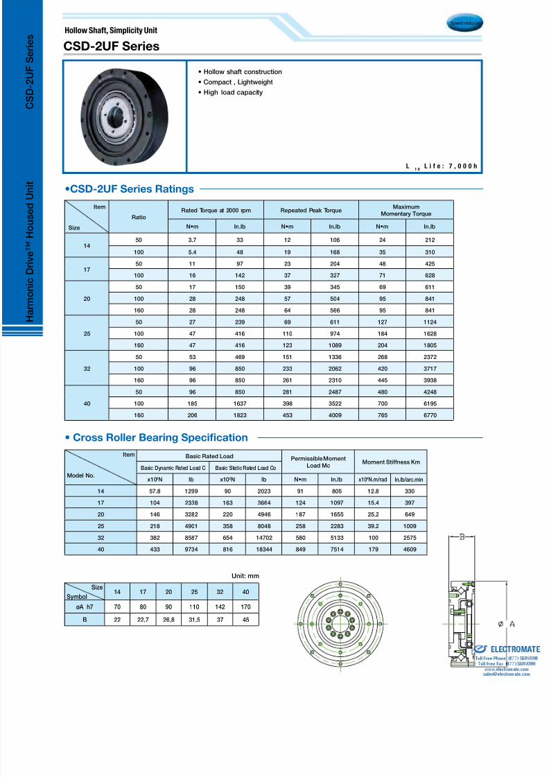
8/3/2019 Harmonic Drive 2010 Catalog
http://slidepdf.com/reader/full/harmonic-drive-2010-catalog 40/56
•CSD-2UF Series Ratings
Size
Symbol14 17 20 25 32 40
øA h7 70 80 90 110 142 170
B 22 22.7 26.8 31.5 37 45
Unit: mm
Speed reducer
Item
Size
RatioRated Torque at 2000 rpm Repeated Peak Torque
MaximumMomentary Torque
N•m In.lb N•m In.lb N•m In.lb
1450 3.7 33 12 106 24 212
100 5.4 48 19 168 35 310
17
50 11 97 23 204 48 425
100 16 142 37 327 71 628
20
50 17 150 39 345 69 611
100 28 248 57 504 95 841
160 28 248 64 566 95 841
25
50 27 239 69 611 127 1124
100 47 416 110 974 184 1628
160 47 416 123 1089 204 1805
32
50 53 469 151 1336 268 2372
100 96 850 233 2062 420 3717
160 96 850 261 2310 445 3938
40
50 96 850 281 2487 480 4248
100 185 1637 398 3522 700 6195
160 206 1823 453 4009 765 6770
Hollow Shaft, Simplicity Unit
L1 0
L i f e : 7 , 0 0 0 h
CSD-2UF Series
• Cross Roller Bearing Specication
• Hollow shaft construction
• Compact , Lightweight
• High load capacity
Item
Model No.
Basic Rated Load Permissible MomentLoad Mc
Moment Stiffness KmBasic Dynamic Rated Load C Basic Static Rated Load Co
x102N lb x102N lb N•m In.lb x104N.m/rad In.lb/arc.min
14 57.8 1299 90 2023 91 805 12.8 330
17 104 2338 163 3664 124 1097 15.4 397
20 146 3282 220 4946 187 1655 25.2 649
25 218 4901 358 8048 258 2283 39.2 1009
32 382 8587 654 14702 580 5133 100 2575
40 433 9734 816 18344 849 7514 179 4609
H a r m o n i c D
r i v e ™
H o u s e d U n i t
C S D - 2 U F S e r i e s
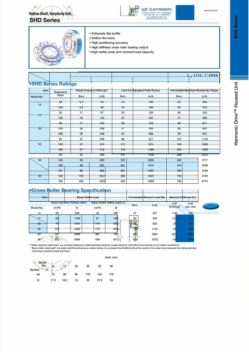
8/3/2019 Harmonic Drive 2010 Catalog
http://slidepdf.com/reader/full/harmonic-drive-2010-catalog 41/56
Speed reducer
Item
Model No.
ReductionRatio
Rated Torque at 2000 rpm Limit for Repeated Peak Torque Permissible Maximum Momentary Torque
N•m In.lb N•m In.lb N•m In.lb
1450 3.7 33 12 106 23 204
100 5.4 48 19 168 35 310
1750 11 97 23 204 48 425
100 16 142 37 327 71 628
20
50 17 150 39 345 69 611
100 28 248 57 504 95 841
160 28 248 64 566 95 841
25
50 27 239 69 611 127 1124
100 47 416 110 974 184 1628
160 47 416 123 1089 204 1805
32
50 53 469 151 1336 268 2372
100 96 850 233 2062 420 3717
160 96 850 261 2310 445 3938
40
50 96 850 281 2487 480 4248
100 185 1637 398 3522 700 6195
160 206 1823 453 4009 765 6770
Item
Model No.
Basic Rated Load Permissible Moment Load Mc Moment Stiffness Km
Basic Dynamic Rated Load C Basic Static Rated Load CoN•m In.lb
x104
N•m/radIn.lb
/arc-minx102N lb x102N lb
14 29 652 43 967 37 327 7.08 182
17 52 1169 81 1821 62 549 12.7 327
20 73 1641 110 2473 93 823 21 541
25 109 2450 179 4024 129 1142 31 798
32 191 4294 327 7351 290 2567 82.1 2114
40 216 4856 408 9172 424 3752 145 3734
•SHD Series Ratings
•Cross Roller Bearing Specication
L1 0
L i f e : 7 , 0 0 0 h
ModelNo.
Symbol
14 17 20 25 32 40
øA 70 80 90 110 142 170
B 17.5 18.5 19 22 27.9 33
Unit: mm
Hollow Shaft, Simplicity Unit
SHD Series
• Extremely at prole
• Hollow thru bore
• High positioning accuracy
• High stiffness cross roller bearing output
• High radial, axial, and moment load capacity
• “Basic dynamic rated load” is a constant stationary radial load that achieves a basic dynamic rated life of the bearing of one million revolutions.
“Basic static rated load” is a static load that achieves a contact stress of a constant level (4kN/mm2) at the center of a contact zone between the rolling element
receiving a maximum load and track.
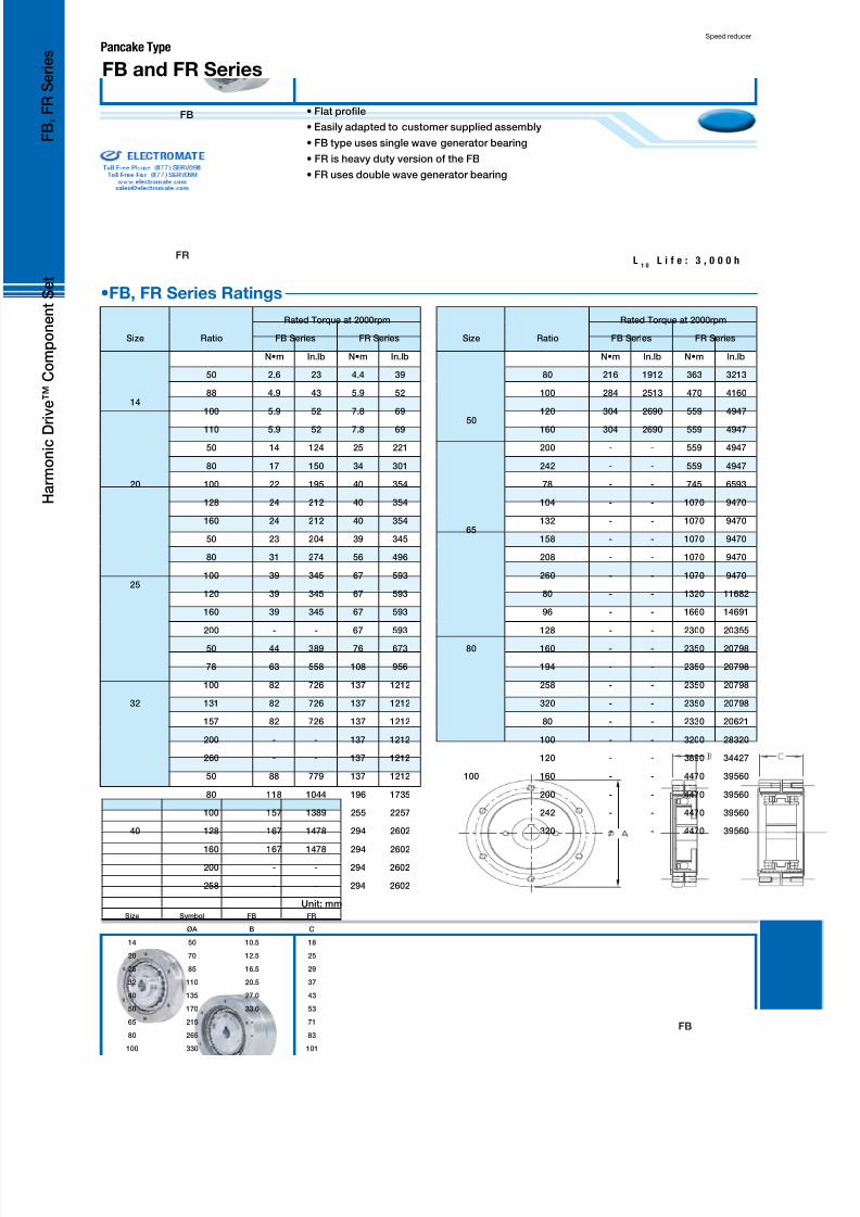
8/3/2019 Harmonic Drive 2010 Catalog
http://slidepdf.com/reader/full/harmonic-drive-2010-catalog 42/56
•FB, FR Series Ratings
FB
FR
Pancake Type
• Flat prole
• Easily adapted to customer supplied assembly
• FB type uses single wave generator bearing
• FR is heavy duty version of the FB
• FR uses double wave generator bearing
L1 0
L i f e : 3 , 0 0 0 h
Speed reducer
Size Symbol FB FR
ØA B C
14 50 10.5 18
20 70 12.5 25
25 85 16.5 29
32 110 20.5 37
40 135 27.0 43
50 170 33.0 53
65 215 - 71
80 265 - 83
100 330 - 101
Unit: mm
FB F
Size Ratio
Rated Torque at 2000rpm
FB Series FR Series
N•m In.lb N•m In.lb
14
50 2.6 23 4.4 39
88 4.9 43 5.9 52
100 5.9 52 7.8 69
110 5.9 52 7.8 69
20
50 14 124 25 221
80 17 150 34 301
100 22 195 40 354
128 24 212 40 354
160 24 212 40 354
25
50 23 204 39 345
80 31 274 56 496
100 39 345 67 593
120 39 345 67 593
160 39 345 67 593
200 - - 67 593
32
50 44 389 76 673
78 63 558 108 956
100 82 726 137 1212
131 82 726 137 1212
157 82 726 137 1212
200 - - 137 1212
260 - - 137 1212
40
50 88 779 137 1212
80 118 1044 196 1735
100 157 1389 255 2257
128 167 1478 294 2602
160 167 1478 294 2602200 - - 294 2602
258 - - 294 2602
Size Ratio
Rated Torque at 2000rpm
FB Series FR Series
N•m In.lb N•m In.lb
50
80 216 1912 363 3213
100 284 2513 470 4160
120 304 2690 559 4947
160 304 2690 559 4947
200 - - 559 4947
242 - - 559 4947
65
78 - - 745 6593
104 - - 1070 9470
132 - - 1070 9470
158 - - 1070 9470
208 - - 1070 9470
260 - - 1070 9470
80
80 - - 1320 11682
96 - - 1660 14691
128 - - 2300 20355
160 - - 2350 20798
194 - - 2350 20798
258 - - 2350 20798
320 - - 2350 20798
100
80 - - 2330 20621
100 - - 3200 28320
120 - - 3890 34427
160 - - 4470 39560
200 - - 4470 39560
242 - - 4470 39560
320 - - 4470 39560
H a r m o n i c D r i v e ™ C o m p o n e n t S e t
FB and FR Series
F B , F R S e r i e s

8/3/2019 Harmonic Drive 2010 Catalog
http://slidepdf.com/reader/full/harmonic-drive-2010-catalog 43/56
• Pancake type
• Ultra compact differential unit
• Backlash is very small and unit requires no assembly adjustment.
• FD Series Ratings
Speed reducer
SizeGearRatio
Rotational Speed r/min.
3500 RPM 2850 RPM 1450 RPM 960 RPM 500 RPM
N•m In.lb N•m In.lb N•m In.lb N•m In.lb N•m In.lb
20
80 29 257 30 266 30 266 30 266 30 266
100 30 266 31 274 36 319 36 319 36 319
128 31 274 34 301 43 381 43 381 43 381
160 32 283 35 310 45 398 49 434 49 434
25
80 46 407 50 443 57 504 57 504 57 504
100 49 434 53 469 67 593 79 699 79 699120 52 460 55 487 70 620 82 726 96 850
160 54 478 57 504 73 646 83 735 108 956
200 55 487 59 522 74 655 84 743 108 956
32
78 98 867 108 956 108 656 108 956 108 956
100 108 956 118 1044 147 1301 157 1389 157 1389
131 108 956 118 1044 157 1389 176 1558 206 1823
157 108 956 118 1044 157 1389 176 1558 216 1912
200 108 956 118 1044 157 1389 176 1558 216 1912
260 108 956 118 1044 157 1389 176 1558 216 1912
40
80 196 1735 196 1735 196 1735 196 1735 196 1735
100 235 2080 245 2168 265 2345 265 2345 265 2345
128 235 2080 245 2168 314 2779 363 3213 372 3292
160 235 2080 245 2168 314 2779 363 3213 451 3991
200 235 2080 245 2168 314 2779 363 3213 451 3991
258 235 2080 245 2168 314 2779 363 3213 451 3991
50
80 353 3124 353 3124 353 3124 353 3124 353 3124
100 441 3903 470 4160 559 4947 559 4947 559 4947
120 441 3903 470 4160 588 5204 666 5894 666 5894
160 441 3903 470 4160 588 5204 676 5983 843 7461
200 441 3903 470 4160 588 5204 676 5983 843 7461
242 441 3903 470 4160 588 5204 676 5983 843 7461
65
78 - - - - 764 6761 764 6761 764 6761
104 - - - - 1100 9735 1190 10532 1190 10532
132 - - - - 1100 9735 1250 11063 1570 13895
158 - - - - 1100 9735 1250 11063 1570 13895
208 - - - - 1100 9735 1250 11063 1570 13895
260 - - - - 1100 9735 1250 11063 1570 13895
80
80 - - - - 1370 12125 1370 12125 1370 12125
96 - - - - 1800 15930 1800 15930 1800 15930
128 - - - - 2180 19293 2490 22037 2710 23984
160 - - - - 2180 19293 2490 22037 3130 27701
194 - - - - 2180 19293 2490 22037 3130 27701
258 - - - - 2180 19293 2490 22037 3130 27701
320 - - - - 2180 19293 2490 22037 3130 27701
100
80 - - - - 2470 21860 2470 21860 2470 21860100 - - - - 3720 32922 3720 32922 3720 32922
120 - - - - 3980 35223 4560 40356 4740 41949
160 - - - - 3980 35223 4560 40356 5720 50622
200 - - - - 3980 35223 4560 40356 5720 50622
242 - - - - 3980 35223 4560 40356 5720 50622
320 - - - - 3980 35223 4560 40356 5720 50622
ModelNo.
Symbol
20 25 32 40 50 65 80 100
øA 85 95 120 145 185 235 290 360
B 73 81 95 113 132 147 178 212
Unit: mm
FD Series Unit TypePhasing Differential

8/3/2019 Harmonic Drive 2010 Catalog
http://slidepdf.com/reader/full/harmonic-drive-2010-catalog 44/56
Phasing Differential
• Pancake type
• Ultra compact differential unit
• Backlash is very small and unit requires no assembly adjustment.
Speed reducer
• FD Series Ratings
SizeGearRatio
Rotational Speed r/min.
3500 RPM 2850 RPM 1450 RPM 960 RPM 500 RPM
N•m In.lb N•m In.lb N•m In.lb N•m In.lb N•m In.lb
20
80 29 257 30 266 30 266 30 266 30 266
100 30 266 31 274 36 319 36 319 36 319
128 31 274 34 301 43 381 43 381 43 381
160 32 283 35 310 45 398 49 434 49 434
25
80 46 407 50 443 57 504 57 504 57 504
100 49 434 53 469 67 593 79 699 79 699
120 52 460 55 487 70 620 82 726 96 850
160 54 478 57 504 73 646 83 735 108 956
200 55 487 59 522 74 655 84 743 108 956
32
78 98 867 108 956 108 656 108 956 108 956
100 108 956 118 1044 147 1301 157 1389 157 1389
131 108 956 118 1044 157 1389 176 1558 206 1823
157 108 956 118 1044 157 1389 176 1558 216 1912
200 108 956 118 1044 157 1389 176 1558 216 1912
260 108 956 118 1044 157 1389 176 1558 216 1912
40
80 196 1735 196 1735 196 1735 196 1735 196 1735
100 235 2080 245 2168 265 2345 265 2345 265 2345
128 235 2080 245 2168 314 2779 363 3213 372 3292
160 235 2080 245 2168 314 2779 363 3213 451 3991
200 235 2080 245 2168 314 2779 363 3213 451 3991
258 235 2080 245 2168 314 2779 363 3213 451 3991
50
80 353 3124 353 3124 353 3124 353 3124 353 3124
100 441 3903 470 4160 559 4947 559 4947 559 4947120 441 3903 470 4160 588 5204 666 5894 666 5894
160 441 3903 470 4160 588 5204 676 5983 843 7461
200 441 3903 470 4160 588 5204 676 5983 843 7461
242 441 3903 470 4160 588 5204 676 5983 843 7461
65
78 - - - - 764 6761 764 6761 764 6761
104 - - - - 1100 9735 1190 10532 1190 10532
132 - - - - 1100 9735 1250 11063 1570 13895
158 - - - - 1100 9735 1250 11063 1570 13895
208 - - - - 1100 9735 1250 11063 1570 13895
260 - - - - 1100 9735 1250 11063 1570 13895
80
80 - - - - 1370 12125 1370 12125 1370 12125
96 - - - - 1800 15930 1800 15930 1800 15930
128 - - - - 2180 19293 2490 22037 2710 23984
160 - - - - 2180 19293 2490 22037 3130 27701
194 - - - - 2180 19293 2490 22037 3130 27701
258 - - - - 2180 19293 2490 22037 3130 27701
320 - - - - 2180 19293 2490 22037 3130 27701
100
80 - - - - 2470 21860 2470 21860 2470 21860100 - - - - 3720 32922 3720 32922 3720 32922
120 - - - - 3980 35223 4560 40356 4740 41949
160 - - - - 3980 35223 4560 40356 5720 50622
200 - - - - 3980 35223 4560 40356 5720 50622
242 - - - - 3980 35223 4560 40356 5720 50622
320 - - - - 3980 35223 4560 40356 5720 50622
ModelNo.
Symbol
20 25 32 40 50 65 80 100
øA 70 85 110 135 170 215 265 330
B 25 29 37 43 53 71 83 101
Unit: mm
H e a d e r
F D P h a s i n g
D i f f e r e n t i a l G e a r S e t
FD Series Component Type
F D S e r i e s

8/3/2019 Harmonic Drive 2010 Catalog
http://slidepdf.com/reader/full/harmonic-drive-2010-catalog 45/56
• 1:1 phasing differential between input and output
• High ratio trim adjustment
• Compact, low backlash design for end roll mounting
• HDB Series Ratings
Speed reducer
Model No.
Symbol20 25 32 40 50
ø A 70 85 110 134 170
B 26.5 34.8 42 56.5 -
Unit: m
Size Ratio
Limit for RepeatedPeak Torque
Maximum Mo-mentary Input
RPM
Rated Output Torque
Input Speed
500 RPM 1000 RPM 1500 RPM 2000 RPM 3000 RPM
lb-in Nm Oil Grease lb-in Nm lb-in Nm lb-in Nm lb-in Nm lb-in Nm
20
80 250 28
6000 3500 373.3 42 296 33 259 29 235 27 206 23100 300 34
120 350 40
160 390 44
25
80 425 48
5000 3500 616.2 70 489 55 427 48 388 44 339 38100 600 68
120 700 79
160 780 88
32
80 950 107
4500 3500 1229 139 976 110 853 96 775 88 677 76100 1200 136
120 1400 158
160 1550 175
40
80 1700 192
4000 3000 2588 292 2054 232 1795 203 1631 184 1425 161
100 2400 271
120 2700 305
160 3100 350
50
80 3100 350
3500 2500 4826 545 3831 433 3347 378 3042 344 2658 300100 4200 475
120 5200 588
160 5800 655
HDB
No Load
Starting
Torque
No Load
Starting
Torque
Input
Inertia
Input
Inertia
in-oz Ncm ib in2 kgcm2
20 4.5 3.2 0.049 0.143
25 6 4.2 0.124 0.363
32 8 5.7 0.45 1.32
40 27 19.1 1.17 3.42
50 50 35.3 3.39 9.91
HDB SeriesPhasing Differential
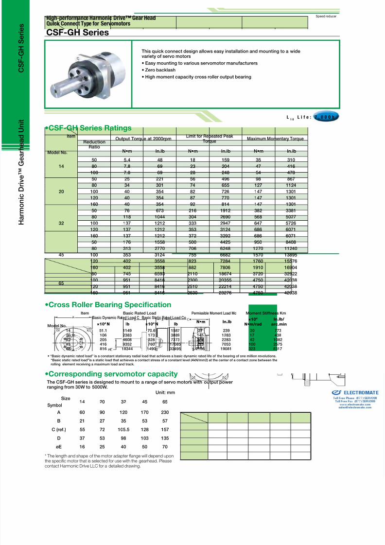
8/3/2019 Harmonic Drive 2010 Catalog
http://slidepdf.com/reader/full/harmonic-drive-2010-catalog 46/56
Speed reducerHigh-performance Harmonic Drive™ Gear HeadQuick Connect Type for Servomotors
CSF-GH Series
This quick connect design allows easy installation and mounting to a widevariety of servo motors
• Easy mounting to various servomotor manufacturers
• Zero backlash
• High moment capacity cross roller output bearing
L1 0
L i f e : 7 , 0 0 0 h
Size
Symbol14 20 32 45 65
A 60 90 120 170 230
B 21 27 35 53 57
C (ref.) 55 72 105.5 128 157
D 37 53 98 103 135
øE 16 25 40 50 70
Unit: mm
* The length and shape o the motor adapter ange will depend uponthe specifc motor that is selected or use with the gearhead. Pleasecontact Harmonic Drive LLC or a detailed drawing.
Item
Model No.
Basic Rated Load Permissible Moment Load Mc Moment Stiffness KmBasic Dynamic Rated Load C Basic Static Rated Load Co
N•m In.lb×104
N•m/rad
In.lb/
arc.min×104 N lb ×104 N lb
14 51.1 1149 70.6 1587 27 239 30 77320 106 2383 173 3889 145 1283 17 43832 205 4608 328 7373 258 2283 42 108245 416 9352 760 17085 797 7053 100 257565 816 18344 1490 33495 2156 19081 323 8317
The CSF-GH series is designed to mount to a range of servo motors with output powerranging from 30W to 5000W.
•Corresponding servomotor capacity
• “Basic dynamic rated load” is a constant stationary radial load that achieves a basic dynamic rated life of the bearing of one million revolutions.“Basic static rated load”is a static load that achieves a contact stress of a constant level (4kN/mm2) at the center of a contact zone between therolling element receiving a maximum load and track.
•Cross Roller Bearing Specication
Item
Model No.
ReductionRatio
Output Torque at 2000rpmLimit for Repeated Peak
TorqueMaximum Momentary Torque
N•m In.lb N•m In.lb N•m In.lb
14
50 5.4 48 18 159 35 310
80 7.8 69 23 204 47 416
100 7.8 69 28 248 54 478
20
50 25 221 56 496 98 867
80 34 301 74 655 127 1124
100 40 354 82 726 147 1301120 40 354 87 770 147 1301
160 40 354 92 814 147 1301
32
50 76 673 216 1912 382 3381
80 118 1044 304 2690 568 5027
100 137 1212 333 2947 647 5726
120 137 1212 353 3124 686 6071
160 137 1212 372 3292 686 6071
45
50 176 1558 500 4425 950 8408
80 313 2770 706 6248 1270 11240
100 353 3124 755 6682 1570 13895
120 402 3558 823 7284 1760 15576
160 402 3558 882 7806 1910 16904
65
80 745 6593 2110 18674 3720 32922
100 951 8416 2300 20355 4750 42038
120 951 8416 2510 22214 4750 42038160 951 8416 2630 23276 4750 42038
•CSF-GH Series Ratings
H a r m o n i c D
r i v e ™
G e a r h e a d U n i t
C S F - G H S e r i e s

8/3/2019 Harmonic Drive 2010 Catalog
http://slidepdf.com/reader/full/harmonic-drive-2010-catalog 47/56
Speed reducer
• High precision Planetary gearhead
• Low backlash: Less than 3 arc min (less than 1 arc min optional)
• Reduction ratios between 3:1 and 45:1
• Easy mounting to various servomotor manufacturers
• High torque capacity
• High moment capacity cross roller output bearing
• High efciency, 90% or higher (85% for Model 14)
• Sealed structure
• Shaft input as well as ange and shaft output versions available
High-performance Harmonic Planetary Gear Head TypeQuick Connect for Servomotors
L1 0
L i f e : 1 0 , 0 0 0 h
HPG Series
The HPG series is designed to mount to a range of servo motors withoutput power ranging from 30W to 5000W.
•HPG Series Ratings
Model
No.
GearRatio
Rated Torque at3000 rpm
RepeatedPeak Torque
Max.MomentaryPeak Torque
N•m In.lb N•m In.lb N•m In.lb
11
5 2.5 22 7.8 69 20 177
9 2.5 22 3.9 35 20 177
21 3.4 30 9.8 87 20 177
37 3.4 30 9.8 87 20 177
45 3.4 30 9.8 87 20 177
14
3 2.9 26 15 133 37 327
5 5.9 52 23 204 56 496
11 7.8 69 23 204 56 496
15 9.0 80 23 204 56 496
21 9 78 23 204 56 496
33 10 89 23 204 56 496
45 10 89 23 204 56 496
20
3 8.8 78 64 566 124 1097
5 16 142 100 885 217 1920
11 20 177 100 885 217 1920
15 24 212 100 885 217 1920
21 25 221 100 885 217 1920
33 29 257 100 885 217 1920
45 29 257 100 885 217 1920
•Corresponding servomotor capacity
Model
No.
GearRatio
Rated Torque at3000 rpm
RepeatedPeak Torque
Max.Monentary
Peak Torque
N•m In.lb N•m In.lb N•m In.lb
32
3 31 274 225 1991 507 4487
5 66 584 300 2655 650 5753
11 88 779 300 2655 650 5753
15 92 814 300 2655 650 5753
21 98 867 300 2655 650 5753
33 108 956 300 2655 650 5753
45 108 956 300 2655 650 5753
50
3 97 858 657 5814 1850 16373
5 170 1505 850 7523 1850 16373
11 200 1770 850 7523 1850 16373
15 230 2036 850 7523 1850 16373
21 260 2301 850 7523 1850 16373
33 270 2390 850 7523 1850 16373
45 270 2390 850 7523 1850 16373
65
4 500 4425 2200 19470 4500 39825
5 530 4691 2200 19470 4500 39825
12 600 5310 2200 19470 4500 39825
15 730 6461 2200 19470 4500 39825
20 800 7080 2200 19470 4500 39825
25 850 7523 2200 19470 4500 39825
Item
Model
Basic Rated Load Allowable Moment Load MC Moment Stiffness Km
Basic Dynamic Rated Load C Basic Static Rated Load CoN•m In.lb
x104
N•m/radIn.lb/
arc-minx102 N lb x102 N lb
11 31.16 700 40.87 919 9.50 84 0.88 23
14 51.1 1149 70.6 1587 32.3 286 3.0 77
20 106 2383 173 3889 183 1620 16.8 433
32 206 4631 328 7373 452 4000 42.1 1084
50 416 9352 760 17085 1076 9523 100 2575
65 906 20367 1480 33270 3900 34515 364 9373
•Cross Roller Bearing Specication
Size
Symbol11 14 20 32 50 65
A 40 60 90 120 170 230
B 15 21 27 35 53 57
C (ref.) 30.5 64 71 104 123 184.5
D 27 37 53 98 103 -
øE 8 16 25 40 50 -
*The length and shape o the motor adapter ange willdepend upon the specifc motorthat is selected or use withthe gearhead. Please contactHarmonic Drive LLC or adetailed drawing.
---- Size 65—Shat is availableas special request. ---
Unit: mm

8/3/2019 Harmonic Drive 2010 Catalog
http://slidepdf.com/reader/full/harmonic-drive-2010-catalog 48/56
Speed reducer
• High precision Planetary gearhead
• Low backlash: Less than 3 arc min (less than 1 arc min optional)
• Easy mounting to various servomotor manufacturers
• High torque capacity
• High moment capacity cross roller output bearing
• Right angle conguration allows for use in limited space
High-performance Right Angle Harmonic PlanetaryGear Head Type/Quick Connect for Servomotors
HPG RA Series
•HPG RA Series Ratings
Size RatioRated Torque
Max. AverageLoad Torque
Limit for RepeatedPeak Torque
Max. MomentaryTorque
N•m In.lb N•m In.lb N•m In.lb N•m In.lb
32
5 66 584 150 1328 150 1328
650 575311 88 779 170 1505
300 265515 92 814 170 1505
21 98 867 170 1505
50
5 170 1505 340 3009 400 3540
1850 16373
11 200 1770 400 3540
850 7523
15 230 2036 450 3983
21 260 2301 500 4425
33 270 2390 500 4425
45 270 2390 500 4425
65
5 400 3540 400 3540 400 3540
4500 39825
12 600 5310 960 8496 960 8496
15 730 6461 1200 10620 1200 10620
20 800 7080 1500 13275 1600 14160
25 850 7523 1500 13275 2000 17700
H a r m o n i c P
l a n e t a r y
®
H P G R A S e r i e s
Item
Model
Basic Rated Load Allowable Moment Load MC Moment Stiffness Km
Basic Dynamic Rated Load C Basic Static Rated Load CoN•m In.lb
x104
N•m/radIn.lb/
arc-minx102 N lb x102 N lb
32 205 4608 328 7373 452 4000 42.1 1084
50 416 9352 760 17085 1076 9523 100 2575
65 906 20367 1480 33270 3900 34515 364 9373
•Cross Roller Bearing Specication
Size A øB C D E* F G
32 120 115H7 35 107 140/175 175/197/217 130/180/220
50 170 165H7 53 144 168/200 209/234/254 130/180/220
65 230 220H8 57 226 168/200 291/316/336 130/180/220
* Left side description: The limited length of the Motor shaft is 81mm.Right side description: The limited length of the Motor shaft is 116mm.
Note:Dimensions F & G depend on the chosen Motor ange square size.Contact Harmonic Drive LLC for special ange motor combination.
Unit: mm
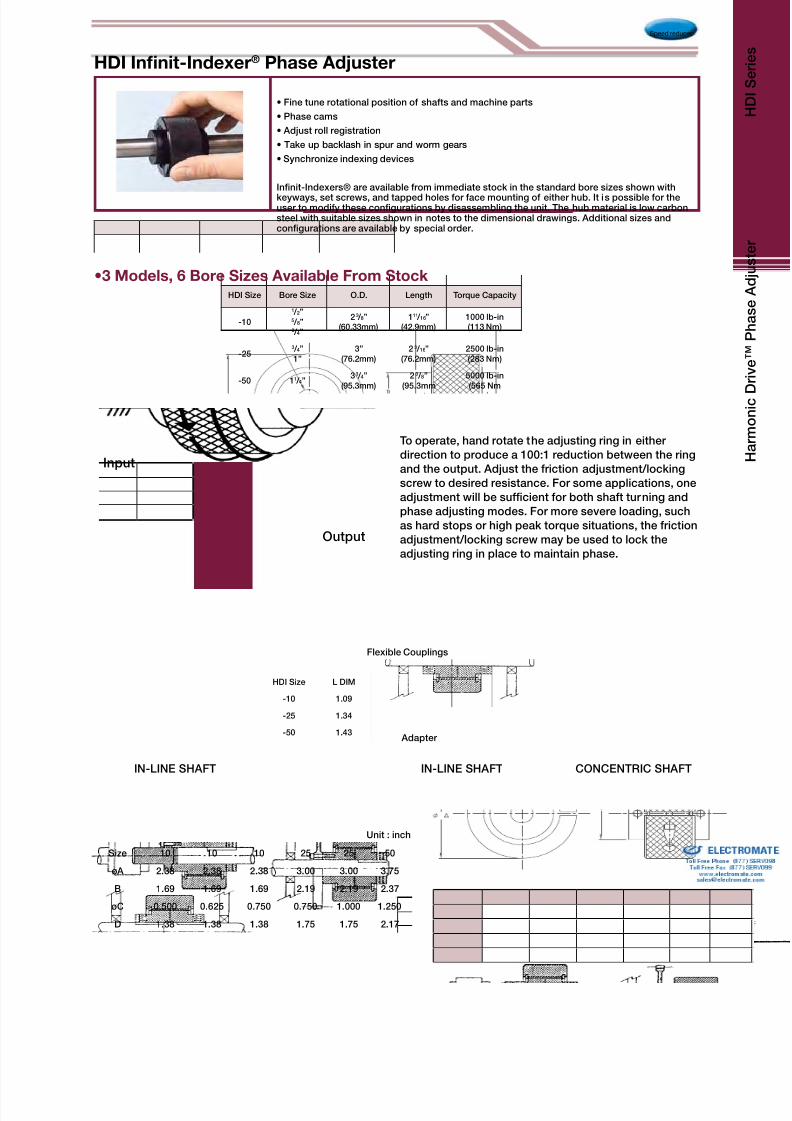
8/3/2019 Harmonic Drive 2010 Catalog
http://slidepdf.com/reader/full/harmonic-drive-2010-catalog 49/56
Speed reducer
HDI Size Bore Size O.D. Length Torque Capacity
-10
1 / 2”5 / 8”3 / 4”
2 3 / 8”(60.33mm)
111 / 16”(42.9mm)
1000 lb-in(113 Nm)
-253 / 4”1”
3”(76.2mm)
2 3 / 16”(76.2mm)
2500 lb-in(283 Nm)
-50 11 / 4”33 / 4”
(95.3mm)2 3 / 8”
(95.3mm5000 lb-in(565 Nm
•3 Models, 6 Bore Sizes Available From Stock
Input
Output
To operate, hand rotate the adjusting ring in either
direction to produce a 100:1 reduction between the ring
and the output. Adjust the friction adjustment/locking
screw to desired resistance. For some applications, one
adjustment will be sufcient for both shaft turning and
phase adjusting modes. For more severe loading, such
as hard stops or high peak torque situations, the friction
adjustment/locking screw may be used to lock the
adjusting ring in place to maintain phase.
• Fine tune rotational position of shafts and machine parts
• Phase cams
• Adjust roll registration
• Take up backlash in spur and worm gears
• Synchronize indexing devices
Innit-Indexers® are available from immediate stock in the standard bore sizes shown with
keyways, set screws, and tapped holes for face mounting of either hub. It is possible for theuser to modify these congurations by disassembling the unit. The hub material is low carbonsteel with suitable sizes shown in notes to the dimensional drawings. Additional sizes andcongurations are available by special order.
IN-LINE SHAFT IN-LINE SHAFT CONCENTRIC SHAFT
Flexible Couplings
Adapter
HDI Innit-Indexer® Phase Adjuster
HDI Size L DIM
-10 1.09
-25 1.34
-50 1.43
Size 10 10 10 25 25 50
øA 2.38 2.38 2.38 3.00 3.00 3.75
B 1.69 1.69 1.69 2.19 2.19 2.37
øC 0.500 0.625 0.750 0.750 1.000 1.250
D 1.38 1.38 1.38 1.75 1.75 2.17
Unit : inch

8/3/2019 Harmonic Drive 2010 Catalog
http://slidepdf.com/reader/full/harmonic-drive-2010-catalog 50/56
Industrial robots
Robot peripheral equipment
Primary axis
End effectors
Linear axis
Indexing table
Peripheral equipment
Joint articulation
Robotic hand
Vision sensor positioning
Torque sensing
Tool changer
Tool magazine
Work positioning equipment
Rotary table
C Axis
Machining centers
Turning centers
NC lathes
Work transfer systems
Grinders
EDM systems
Bending machines
Rolling machines
Presses
Work transfer systems
Bending axis
Work positioning
Work transfer
Printing presses
Folding machines
Paper changing machines
Paper positioning machines
Paper machines
Web tension control
Cutting blade positioning
Phase adjusting
Head box slice lip positioning
Roller height adjustment
Humanoid Robots
Robots
Humanoid Robots
Metal Machine Tools
Metal Working Machines
Printing, Bookbinding and Paper Processing Machines
Applications
CSG
CSD
CSF
SHG
SHFSHD
HPG
CSG
CSD
CSF
SHG
SHF
SHD
HPG
FHA-Mini
FHA-C
RSF
Micro
Encoder
FHA-C
RSF
LAH
CSG
CSF
SHG
SHF
HPG
FHA-C
RSF
LSA
SHG
SHF
HPG
RSF
CSG
CSF
SHG
SHF
FB
FR
FD
HPG
FHA-C
FHA-Mini
FHA-C
RSF-Supermini
RSF-Mini
MicroEncoder

8/3/2019 Harmonic Drive 2010 Catalog
http://slidepdf.com/reader/full/harmonic-drive-2010-catalog 51/56
X-ray analytical systems
Optical component inspectionsystems
Laser oscillation machines
Optical measuring instruments
Surface inspection systems
Optical disc manufacturingsystems
Laser markers
Three-dimensional manipulators
X-ray photographing and CT-NMR
systems
X-ray lm developing and take-off
machines
Surgical operation assistant robots
X, Y, Z axis drive
Indirect drivemechanisms
Condenser mirror adjustingmechanisms
Electromagnetic wave
micrometer adjustingmechanisms
Secondary mirror position control
Robot arms for maintenance
servicing
Positioning table drive
Lens positioning drive
Laser mirror drive
Prism drive
Probe drive
Sensor positioning drive
Precision joint drive
Bed lifting and inclination drive
Positioning table drive
Photometric equipment
Three-dimensionalmeasuring instruments
Metal tensile test machines
Soil-column yield strengthtest machines
Transfer systems
Positioning drive
Prism positioning drive
Indexing tables
Direct transmission tables
Mask and reticle
manufacturing
Wafer fabrication
equipment
Wafer processing
equipment
Test & Assembly equipment
Inspection equipment
Wafer transfer equipment
Wafer transfer robots
Positioning drive
Indexing tables
Wafer ipper
Valve opening/closing
Telescopes
Optical Machines
Medical Equipment
Semiconductor Manufacturing Systems
FHA-Cmini
FHA-C
RSF
RSF-Supermini
KDURH
LA
LAH
MicroEncoder
CSF
SHD
SHFHPG
FHA-C mini
RSF
RSF-Supermini
KDU
RH
LSA
MicroEncoder
FHA-Cmini
FHA-C
RSF
RH
CSF
SHF
FHA-Cmini
RSF
RSF-Supermini
KDU
RH
LSA
MicroEncoder
CSF
SHF
FHA-Cmini
RSF-Supermini
RSF
KDU
LA
LAH
LBC
CSF
SHF
HPG
CSF
SHF
Measurement, Analytical and Test Systems

8/3/2019 Harmonic Drive 2010 Catalog
http://slidepdf.com/reader/full/harmonic-drive-2010-catalog 52/56
Wood, Light Metal and Plastic Machine Tools
FHA-Cmini
FHA-C
RSF
RSF-Supermini
LAHCSG
CSF
SHG
SHF
HPG
FHA-C
CSF
FR
Oil exploration robot
Wind power equipment
Electric power equipment
Photovoltaics
RSF
FHA-C
RH
CSF
SHF
HPG
Sealing machines
Label printing machines
Label attaching machines
Robots
Work transfer systems
Shaft synchronizing drive
Roll synchronizing drive
Joint drive
Trolley drive
FHA-C
RSF
RH
CSF
SHF
FB
FR
FD
Transfer systems
Parts positioning drive
Indexing tables
Direct transmission tables
Work reversing machines
Tension controllers
Hatch opening/closing drive
Joint drive
Trolley drive
FHA-Cmini
FHA-C
RSF
RSF-Supermini
KDU
RH
LA
LAH
Paper-making Machines
Energy
Crating and Packaging Machines
Flat Panel Display Manufacturing Systems
CSF
SHF
SHD
HPG
Woodworking machines
5-shaft machining centers
Large 3-dimensionprocessing machines
Work transfer systems
Paper-making machines
Corrugated berboard box
making and printing machines
Digging angle positioning drive
Propeller angle positioning drive
Condensing board positioningdrive
Coating-process rollerpositioning drive
Paper thickness adjustingmechanism drive
Cutter knife positioning
Cutter knife traveling drive
Array process equipment
Cell process equipment
Assembly processequipment
Work transfer systems
Milling head drive
Tool revolver drive
Tool changer drive
Tool magazine drive
Work positioning machines
Rotary table drive
Tool positioning machine drive
Direct transmission shaft drive
Shaft drive
HPG
Applications

8/3/2019 Harmonic Drive 2010 Catalog
http://slidepdf.com/reader/full/harmonic-drive-2010-catalog 53/56
Drilling head drive
Tool changer drive
Tool magazine drive
Work positioning machines
Rotary table drive
Tool positioning machine drive
Shaft drive
Flight simulators
Cargo handling and transfersystems
Reconnaissance cameras
Valves
Antennas
Microphones
Cameras
Wavelength duplexers
Radars
Pan & Tilt drives
Prism drive
Communication Equipment
FHA-C mini
FHA-C
RSF
RSF-Supermini
RHLA
LSA
HPG
Electronic component
insertion machines
Solder paste dispensing
machines
Board inspection systems
Transfer systems
Printed Circuit Board Manufacturing Machines
FHA-C mini
FHA-C
RSF
RSF-Supermini
LAH
CSG
CSF
SHG
SHF
HPG
Communication Antennas
Solar cell paddles
Robotic joints
Robotic arms
Pan & Tilt drive
Joint drive
Wheel drive
Valve actuator
Trolley drive
Cargo wheel power
drive unit
Fly-by-Wire Components
CSF
SHF
SHD
Space Equipment
Aircraft
FHA-Cmini
FHA-C
RSF
RSF-Supermini
RH
CSF
HPG
Ceramic forming machines
Glass polishing machines
Sheet glass cuttingmachines
Valve opening and closing
Valve positioning
Traveling trolley drive
FHA-Cmini
FHA-C
RSF
LSA
CSF
SHF
HPG
Glass and Ceramic Manufacturing Systems
MicroEncoder

8/3/2019 Harmonic Drive 2010 Catalog
http://slidepdf.com/reader/full/harmonic-drive-2010-catalog 54/56
Semiconductor ManufacturingSystems
Optical Machines
Paper-making Machines
Flat Panel Display Manufacturing Systems
Printed Circuit BoardManufacturing Machines
Aircraft
Wood, Light Metal and PlasticMachine Tools
Rob
Humanoid Robots
Printing, Bookbindingand Paper
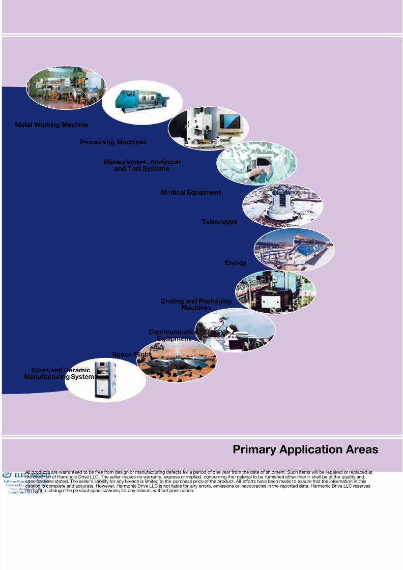
8/3/2019 Harmonic Drive 2010 Catalog
http://slidepdf.com/reader/full/harmonic-drive-2010-catalog 55/56
All products are warranteed to be free from design or manufacturing defects for a period of one year from the date of shipment. Such items will be repaired or replacethe direction of Harmonic Drive LLC. The seller makes no warranty, express or implied, concerning the material to be furnished other than it shall be of the quality andspecications stated. The seller’s liability for any breach is limited to the purchase price of the product. All efforts have been made to assure that the information in thcatalog is complete and accurate. However, Harmonic Drive LLC is not liable for any errors, omissions or inaccuracies in the reported data. Harmonic Drive LLC resethe right to change the product specications, for any reason, without prior notice.
Primary Application Are
Metal Working Machine
Processing Machines
Measurement, Analyticaland Test Systems
Medical Equipment
Telescopes
Crating and PackagingMachines
CommunicationEquipment
Space Flight
Glass and CeramicManufacturing Systems
Energy

8/3/2019 Harmonic Drive 2010 Catalog
http://slidepdf.com/reader/full/harmonic-drive-2010-catalog 56/56
Group Companies
Harmonic Drive Systems, Inc.
6-25-3 Minami-Ohi, Shinagawa-ku
Tokyo 141-0013, Japan
Harmonic Drive AGHoenbergstrasse, 14, D-6555
Limburg/Lahn Germany
Harmonic Drive LLC
247 Lynnfield StreetPeabody, MA 01960
T: 800.921.3332T: 978.532.1800F: 978.532.9406
www.HarmonicDrive.net