reduce the sediment resuspension caused …ad-a 146 898 miscellaneous paper hl-84-3 u a techniques...
TRANSCRIPT

AD-A146 898 TECHNIQUES TO REDUCE THE SEDIMENT RESUSPENSION CAUSED 1/iBY DREDGING(U) ARMY ENGINEER WATERWAYS EXPERIMENTSTATION VICKSBURG MS ENVIRONMENTAL LAB G L RAYMOND
UNCLASSIFIED SEP 84 WES/MP/HL-84- F/G 13/2 N

1.0 1 11 .5-
L138
1.2111.
'(WY RESOLUTIO TEST CHART

AD-A 146 898MISCELLANEOUS PAPER HL-84-3
U A TECHNIQUES TO REDUCE THE SEDIMENT _RESUSPENSION CAUSED BY DREDGING
by -2
Gene L. RaymondEnvironmental Laboratory
DEPARTMENT OF THE ARMYWaterways Experiment Station, Corps of Engineers
PO Box 631Vicksburg, Mississippi 39180-0631 .
September 1984
Final Report
Approved For Public Release; Distribution Unlimited
DTIC'!ECTE
~OC T3 0 84 0
HYDRAULICSPrepared for
DEPARTMENT OF THE ARMYLABORATORY US Army Corps of Engineers
Washington, DC 20314-1000
~py /0 ~ 0/0i
* . . -. '.
it to the originator.
.
The findings in this report are not to be construed as an officialDepartment of the Army position unless so designated
L.
L
by other authorized documents.
I,
The contents of this report are not to be used foradvertising, publication, or promotional purposes.Citation of trade names does not constitute anofficial endorsement or approval of the use of
such commercial products. L
,...

UnclassifiedSECURITY CLASSIFICATION OF THIS PAGE (When Date Entered)
REPORT DOCUMENTATION PAGE READ INSTRUCTIONSBEFORE COMPLETING FORM
I. REPORT NUMBER 2. GOVT ACCESSION NO. 3. RECIPIENT'S CATALOG NUMBER
Miscellaneous Paper HL-84-3 tn'qL. 5' 14. TITLE (ind Subtitle) S. TYPE OF REPORT & PERIOD COVERED
TECHNIQUES TO REDUCE THE SEDIMENT RESUSPENSION Final reportCAUSED BY DREDGING
6. PERFORMING ORG. REPORT NUMBER
7. AUTHOR(P) 8. CONTRACT OR GRANT NUMBER(e) "
Gene L. Raymond
9. PERFORMING ORGANIZATION NAME AND ADDRESS 10. PROGRAM ELEMENT. PROJECT. TASKAREA 4 WORK UNIT NUMBERSUS Army Engineer Waterways Experiment
Station
Environmental Laboratory
PO Box 631, Vicksburg, Mississippi 39180-0631
I1. CONTROLLING OFFICE NAME AND ADDRESS 12. REPORT DATE
DEPARTMENT OF THE ARMY September 1984
US Army Corps of Engineers 13. NUMBER OF PAGES
Washington, DC 20314-1000 3314. MONITORING AGENCY NAME & ADRESS(If different from Controlling Office) IS. SECURITY CLASS. (of thise report) - .
Unclassified - 0
IS&. DECLASSIFICATION/DOWNGRADINGSCHEDULE
IS. DISTRIBUTION STATEMENT (of tile Report)
Approved for public release; distribution unlimited.
17. DISTRIBUTION STATEMENT (of the abetrac entered In Block 20. If different fromt Report)
IS. SUPPLEMENTARY NOTES
Available from National Technical Information Service, 5285 Port Royal Road,
Springfield, Virginia 22161.
It. KEY WORDS (Continue on reerse side It neceeeary end Identify by block number) 5
Dredging--Technique (LC)
Sediments, Suspended (LC)
Dredges (LC)
20, A9SFACr (C..tmt A ftm.. nceeemy and Identify by block number)
-)As part of a larger effort-,under the Improvement of Operation and Main- -
tenance Techniques Program-to develop a method to predict the extent of sedi-ment resuspension and contaminant release when dredging in contaminated sedi-
ments,Lthe U. S. Army Engineer Waterways Experiment Station's Water ResourcesEngineering Group is conducting',field studiesAto evaluate new and existing -.-
dredging methods. These studies consist of efforts to determine the level ofsediment resuspended by a given dredge type in a given sediment. Whenever
(Continued) .i . -DO 'FR la 610 Of I NO V G S I S OBSOLE
TE[
" I" 1 1'
D AN 1- Unclassified
SECURITY CLASSIFICATION OF THIS PA.E (When D.e Ent,"d)
S . .*°

Unclassified
SECURITY CLASSIFICATION OF THIS PAGE1116 Date *' .
20. ABSTRACT (Continued).
-possible, the studies are conducted such that different dredges operateunder the same conditions or even in the same locations. The studies alsoevaluate the effects of various operational parameters on the resuspensionof sediments. This paper presents the results of the first 2 years of studyand includes data from both field studies and extensive literature review.
Different dredge types produce different amounts of suspended sedimentin different parts of the water column. Resuspensions caused by cutterheadand hopper dredges tend to remain in the lower water column, while bucketdredges increase resuspensions throughout the water columns. The amount ofresuspension caused by a given dredge type also depends on the operating tech-niques used with the dredge.
Sediment resuspension can be lessened by changing operating techniques,as in the case of the cutterhead, or by modifying the equipment, such asenclosing a clamshell bucket. Special purpose dredges can also be used3toreduce sediment resuspension, Cbut their lower production rates limit theirapplication.
L
Unclassified
SECURITY CLASSIFICATION OF THIS PAGE(1fl'n Date Entered)
, - . . . . . . . . . . . . -
-, -. .. . - ., . : - . . . .... . . . . . ... . ... .. _,II I. .-. " . . - .. - - ...
PREFACE
This work was conducted under the Dredging Contaminated Sediments Work
Unit as part of the Improvement of Operations and Maintenance Techniques .
(IONT) Program at the US Army Engineer Waterways Experiment Station (WES),
Vicksburg, Miss. The IOMT Program is sponsored by the Office, Chief of Engi-
neers (OCE), U. S. Army, with overall program management assigned to the WES
Hydraulics Laboratory (HL). This specific work unit was further assigned to 5
the WES Environmental Laboratory (EL) and managed through the Environmental
Effects of Dredging Programs (EEDP).
The work was conducted by MAJ Gene L. Raymond, Water Resources Engi-
neering Group (WREG), Environmental Engineering Division (EED), EL, under the
direct supervision of Mr. Michael R. Palermo, Chief, WREG; and Dr. Raymond L.
Montgomery, Special Assistant, EED; and under the general supervision of
Mr. Andrew J. Green, Chief, EED; and Dr. John Harrison, Chief, EL. Program
Manager for the IOMT was Mr. Richard A. Sager, HL, and Program Manager for Sthe EEDP was Mr. Charles C. Calhoun, Jr., EL. Messrs. J. Gottesman and
Charles Hummer were the OCE Technical Monitors.
Comander and Director of WES during the preparation of this report was
COL Tilford C. Creel, CE. Technical Director was Mr. F. R. Brown. S
This report should be cited as follows:
Raymond, G. L. 1984. "Techniques to Reduce the Sediment -
Resuspension Caused by Dredging," Miscellaneous Paper HL-84-3, IUS Army Engineer Waterways Experiment Station, Vicksburg,Mississippi.
Accession Fo.
NTIS GRA&IDTIC TAB.-
Jultiffcatio ,
Distribution/ ""-
Availability Codes1 "'Avail and/orDist Special
1 _ _ _ _,._,_
• "
•'-. ":' -I..-
CONTENTS
Page
PREFACE.......................... . ...... . .. . .. .. .. .. .... 1
*LIST OF FIGURES .. ............................. 3
CONVERSION FACTORS, U. S. CUSTOM4ARY TO METRIC (SI) UNITSOF MEASUREMENT. ............................. 4
PART I: INTRODUCTION................... .. . . ... . ... .. .. .. .....
Background. ............................. 5Purpose and Scope .. ......................... 6
*PART II: SEDIMENT RESUSPENSION FROM DREDGING. .......... ..... 7
Nature of Resuspended Sediment .......... .......... 7Characteristics of Various Dredges . .................. 8 .
Comparison of Dredge Resuspension .. ................. 15
PART III: LIMITING SEDIMENT RESUSPENSION .. ................ 18
Cutterhead Dredge Operations. .................... 18Hopper Dredge Operations. ...................... 21Clamshell Bucket Dredge Operations. ................. 23Special-Purpose Dredges .. ...................... 25L
PART IV: CONCLUSIONS AND RECOMMENDATIONS .. ................ 30
Conclusions .. ............................ 30
Recommendations .. .......................... 30
REFERENCES ............ .................... 32-
2

- . - .- - .- _
LIST OF FIGURES
No. Page
1 Characteristics of suspended solids in the water columnin the vicinity of dredging and disposal operations .. ...... 8
2 Cross-sectional view of typical cutterhead suctiondredgehead ............ ........................... 9 -.
3 Schematic representation of average suspended sedimentvalue for indicated depths and distances, James Rivercutterhead test ......... ........................ ... 10
4 Postulated double plume resulting from hopper dredgeoperations ........... ........................... ... 12
5 Locations of radials and sampling points along the radialsused for the Jacksonville clamshell comparison test ...... . 14
6 Schematic representation of average suspended sediment
levels for indicated distances and depths, Jacksonvilleclamshell comparison ......... ...................... ... 14
7 Comparison of average suspended sediment values for acutterhead operation and a clamshell operation .. ......... ... 17
8 Effect of cutterhead shape on suction height above thebottom ............ ............................. ... 20
9 Schematic front view of a cutterhead showing the cuttertooth rake angle .......... ........................ ... 21
10 Schematic drawing of a hopper dredge bin equipped with theJapanese designed Anti-Turbidity Overflow System (ATOS) . . .. 22 p
11 Average suspended sediment levels along sampling radials
during clamshell dredging for Jacksonville comparison test . . 25
12 Operating cycle of Pneuma pump ....... .................. ... 26
* 13 Clean-Up System dredgehead ........ .................... ... 27
14 Front and side view of Japanese Refresher System .. ......... ... 29
3p.
I ":.. . . . . "I :: : : : - :

CONVERSION FACTORS, U. S. CUSTOMARY TO METRIC (SI)UNITS OF MEASUREMENT
U. S. customary units of measurement used in this report can be converted to
metric (SI) units as follows:
Multiply By To Obtain
cubic yards 0.7645549 cubic metres
feet 0.3048 metres
feet per second 0.3048 metres per second
inches 25.4 millimetres
U4
ID
• °
I
Iilii -
S..'° .

TECHNIQUES TO REDUCE THE SEDIMENT RESUSPENSION CAUSED BY DREDGING
PART I: INTRODUCTION •0
Background
1. During the last 100 years, the sediments of the Nation's waterways -
have increasingly become repositories for a variety of contaminants. This
contamination is a result of river commerce, industrial activities, widespread
use of pesticides in agriculture, and intentional or inadvertent dumping of
pollutants. Regardless of the source of pollution, today's dredging activi-'4
ties frequently must be conducted within this contaminated environment. How-
ever, dredging equipment and practices in the United States evolved in an era
when the major emphasis was to achieve the greatest possible economic returns
through maximizing production, with only secondary consideration given to -
environmental impacts. As a result, conventional dredges are not specifi-
cally designed for operation in highly contaminated sediments. Therefore,
some modification of either existing equipment or operating methods may be
necessary when dredging highly contaminated sediments.
2. Sediments become contaminated because of the affinity of contami-
nants, particularly chlorinated hydrocarbon pesticides and polychlorinated
biphenyls (PCBs), for the clay-sized particles and natural organic solids
found in most river sediments. When sediments are disturbed, such as during
dredging operations, contaminants may be transferred to the water column
either through resuspension of the sediment solids, dispersal of interstitial
water, or desorption from the resuspended solids. Investigations by Fulk,
Gruber, and Wullschleger (1975) showed that, for sediment concentrations of
less than 100 g/1, the amount of pesticides and PCBs that are dissolved or
desorbed into the water column from the resuspended sediment is negligible.
They determined that basically all contaminants transferred to the water -
column were due to the resuspension of solids. They also reported that the
reduction of suspended solids concentrations due to settling resulted in a
decrease in contaminant concentrations. The spread of contaminants during
dredging operations is therefore linked to the resuspension of sediments, -
particularly clay-sized and organic particles.
3. In addition to the concern of conducting dredging operations in
S~• .. .
contaminated sediments, Federal, state, and local environmental regulatory
agencies have set standards for the resuspension of sediments in general.
The resuspension of sediments is usually referred to in the regulations in
terms of turbidity, which is an optical term describing the cloudy appearance
of water. Regulatory standards for turbidity are usually motivated by a
concern for the suspected effects of suspended material on aquatic plants or
animals.
4. The U. S. Army Engineer Waterways Experiment Station (WES) has
initiated studies to determine the relative effectiveness of various methods
of dredging contaminated sediments. These studies are being conducted as part
of the Improvement of Operation and Maintenance Techniques (IOMT) Program.
The specific environmental concerns addressed include resuspension of contam-
inated sediments and the possibility of contaminant release during the dredg-
ing operation. This question of dredging in contaminated sediments is being
addressed in three ways: the assembly and evaluation of available domestic
and foreign information concerning sediment resuspension and contaminant re-
lease, the development of appropriate laboratory tests to predict contaminant
release from resuspended sediments, and the use of field studies to monitor
performance and compare dredges operating under various conditions. j -
Purpose and Scope
5. The purpose of this paper is to present the findings from ongoing
research efforts. It will discuss the sediment resuspension characteristics
of various conventional dredges, provide a comparison between the dredge types -
with respect to sediment resuspension and water column effects, and present
D methods for limiting the sediments resuspended by conventional dredges. Sev-
eral special-purpose dredges that may have potential to limit sediment resus-
pension are also introduced. This report is based on an extensive review of
foreign and domestic information on sediment resuspensions due to dredging
and on the results of field studies conducted under the IOMT Program.
6 m
6!

PART II: SEDIMENT RESUSPENSION FROM DREDGING
Nature of Resuspended Sediment
6. Investigations by Wechsler and Cogley (1977) found that the material
resuspended during dredging consists primarily of silt, clay, and organics.
This resuspended material is sometimes referred to in terms of turbidity.
While turbidity, which describes an optical property of water, can give an
indication of the extent of sediment resuspension, it cannot be used to quan-
titatively describe the amount of resuspended sediments. Turbidity cannot be
consistently correlated with weight concentration of suspended matter because
the optically important factors of size, shape, and refractive index of the
particulate materials bear little relationship to the concentration and spe-
cific gravity of the suspended matter. Turbidity cannot be used to tell which
grain sizes contribute most to the resuspension problem. Therefore, whenever ...
possible, comparisons of dredge resuspension will be made in terms of sus-
pended solids as determined by gravimeteric analysis.
7. Wechsler and Cogley (1977) reported that the coarse-grained frac-
tions (>74 p) settle rapidly under normal conditions of water turbulence and
thus do not contribute significantly to the turbid appearance of water. Silt
comprises the nonclay mineral fraction of sediment and has a grain size of
2 to 74 p. Although silt particles, with settling rates as low as I cm/hr,
may contribute to turbidity, in most cases the clay fraction and the organic
matter are mainly responsible for the turbid appearance of water in the vi-
cinity of dredging operations.
8. Extensive reviews of the literature concerning sediment resuspen-
sion caused by dredging were conducted by Barnard in 1978 and more recently
by Herbich and Brabme (in press). They found that most conventional dredges
create low-solids-concentration plumes of silt- and clay-sized particles or
small flocs that settle through the water column at very slow rates. Although
the solids concentration in the water column in the vicinity of the dredging
operation usually does not exceed several hundred milligrams per litre, the
particles continue to settle until the solids concentration near the bottom
can exceed 10 g/2. Barnard (1978) referred to this level of solids concentra-
tion (0 to 10 g/£) as turbidity (Figure 1). Higher concentrations take on the
properties of fluid mud. Barnard noted that the nature, degree, and extent
7

DREDGED MATERIAL SUSPENSIONS
QUALITATIVE SOLIDS BULKDESCRIPTOR PROCESSES CONCENTRATION (g/R) DENSITY (g/cc) °
AVERAGE (RANGE) AVERAGE (RANGE)
O og/1 1.000INDEPENDENT
SETTLING 10g/E (5-20) 1.006 (1.003-1.012)SEDIMENTATION
LOW HINDERED OR
DENSITY ZONE SETTLING
FLUID MUD 200g/2 (175-225) 1.125 (1.109-1.140)
HIGHDENSITY
DENSITYSELF-WEIGHTTYPICAL BOTTOM CONSOLDATION 400g/V (300-500) 1.249 (1.187-1.3111
SEDIMENT
'ASSUME SOLIDS = 2.65 g/ccWATER = 1.00 g/cc
Figure 1. Characteristics of suspended solids in the water column inthe vicinity of dredging and disposal operations (Barnard 1978)
of sediment resuspension are controlled by many factors, including character-
istics of the sediment, hydrologic regime, and hydrodynamic forces.
Characteristics of Various Dredges
9. In addition to the characteristics of sediments that contribute to
resuspension, different types of dredges generate different levels of resus-
pended sediment. Both the type of equipment and the operating techniques used
with the equipment are important. This section will discuss some of the com-
monly used dredges and their potential for causing sediment resuspension dur-
ing operations.
Cutterhead dredges
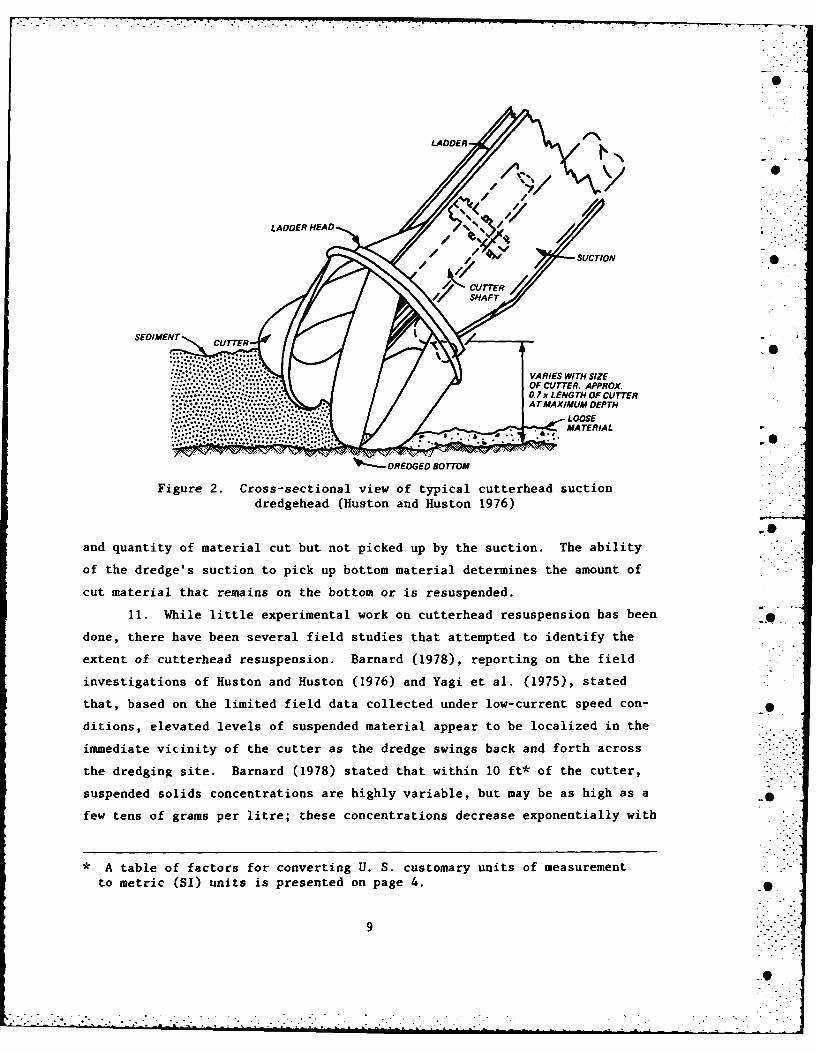
10. The cutterhead dredge is basically a hydraulic suction pipe com-
bined with a cutter to loosen material that is too consolidated to be removed
by suction alone (Figure 2). This combination of mechanical and hydraulic
systems makes the cutterhead one of the most versatile and widely used dredg- |-
ing systems; however, its use also increases the potential for sediment resus-
pension. While a properly designed cutter will cut and guide the bottom
material toward the suction efficiently, the cutting action and the turbulence
associated with the rotation of the cutter resuspend a portion of the bottom
material. The level of sediment resuspension is directly related to the type
8
0
.0:
OF CUTER. PPROXLADDER HEAD /: .V / -SUCTION •
CUTTERSHAFT '
:.." :VARIES WITH SIZE..... OF CUTTER. APPROX.
...:. ... 0. 7x L ENG TH OF CUTTER
ATMAXIMUM DEPTHL OOSE" .. _ ,, *: . MATERIAL
~~'-DREDGED BOTTOM
Figure 2. Cross-sectional view of typical cutterhead suction
dredgehead (Huston and Huston 1976)
and quantity of material cut but not picked up by the suction. The ability
of the dredge's suction to pick up bottom material determines the amount of
cut material that remains on the bottom or is resuspended.
11. While little experimental work on cutterhead resuspension has been
done, there have been several field studies that attempted to identify the
extent of cutterhead resuspension. Barnard (1978), reporting on the field
investigations of Huston and Huston (1976) and Yagi et al. (1975), stated
that, based on the limited field data collected under low-current speed con-
ditions, elevated levels of suspended material appear to be localized in the
immediate vicinity of the cutter as the dredge swings back and forth across
the dredging site. Barnard (1978) stated that within 10 ft* of the cutter,
suspended solids concentrations are highly variable, but may be as high as a _•
few tens of grams per litre; these concentrations decrease exponentially with
* A table of factors for converting U. S. customary units of measurement
to metric (SI) units is presented on page 4.
9
-! .
depth from the cutter to the water surface. Near-bottom suspended solids
concentrations may be elevated to levels of a few hundred milligrams per litre
at distances of 1000 ft from the cutter.
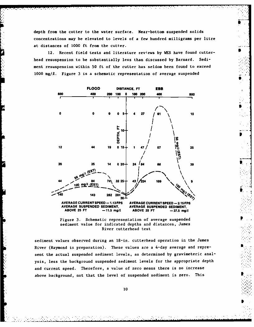
12. Recent field tests and literature reviews by WES have found cutter-
head resuspension to be substantially less than discussed by Barnard. Sedi-
ment resuspension within 50 ft of the cutter has seldom been found to exceed
1000 mg/2. Figure 3 is a schematic representation of average suspended
FLOOD DISTANCE, FT EBB800 400 200 100 0 100 200 400 600
I I I I I I I I
f X I.
0 0 0 05 4 27 /61 \ 15
10--0 / I
12 44 19 0 15" 1 47/ 57 Ve 25
/ -4:
20 25 14 0 20- 24 184 66 39
44 1- 84 74\ 32 25" 43,/A24 199
0 143 282 281 130
AVERAGE CURRENT SPEED - 1.13 FPS AVERAGE CURRENT SPEED - 2.15 FPSAVERAGE SUSPENDED SEDIMENT, AVERAGE SUSPENDED SEDIMENT,
ABOVE 25 FT -11.5 mg/ ABOVE 25 FT -37.5 mg/"
Figure 3. Schematic representation of average suspendedsediment value for indicated depths and distances, James
River cutterhead test
sediment values observed during an 18-in. cutterhead operation in the James
River (Raymond in preparation). These values are a 4-day average and repre-
sent the actual suspended sediment levels, as determined by gravimeteric anal-
ysis, less the background suspended sediment levels for the appropriate depth
and current speed. Therefore, a value of zero means there is no increase
above background, not that the level of suspended sediment is zero. This
10
!I I
.. -

figure highlights several characteristics of cutterhead dredges. First, as
pointed out by Barnard (1978) and Herbich and Brahme (in press), and suggested
by intuition, depth has an important correlation to suspended sediment level.
Secondly, even though the plume of resuspended material has its source at the 0
bottom, some material appears to move upward surprisingly fast. This upward
movement is probably connected to the action of the cutter. Finally, the ef-
fect of the different average ambient current speeds can be seen. The higher
current speed at ebb tide appears to propel the resuspended sediments higher
in the water column, thus making the overall average suspended sediment values
higher for the ebb than the flood. The salinity was similar during both
phases and well below the level required to produce stratification. The
average suspended sediment values of the flood and ebb for the upper water .
column (25-ft level and above) are 11.5 mg/2 and 37.5 mg/l, respectively.
This difference is statistically significant at the 95-percent confidence
level. In this case, the effects of dredging in higher current velocity will
be magnified over that of lower current velocities. It appears that for cur- .
rent speeds in the 2-fps range the sediment was sufficiently hindered to pre-
vent the settling rate that occurred at the lower current velocities. This
effect cannot be confirmed in the lower water column however.
Hopper dredges
13. Hopper dredges are used mainly for maintenance dredging in bar
areas and shipping channels where traffic and operating conditions rule out .".
the use of stationary dredges. As the dredge moves forward, the bottom sedi-
ment is hydraulically lifted from the channel bottom with a draghead, trans-
ported up the dragarm (i.e., trailing suction pipe), and temporarily stored in
hopper bins in the ship's hull. host modern hopper dredges have one or two
dragarms mounted on the side of the dredge and have storage capacities ranging
from several hundred to over 12,000 cu yd. During the filling operation,
pumping of the dredged material slurry into the hoppers is often continued
after the hoppers have been filled in order to maximize the amount of high-
density material in the hopper. The low-density turbid water at the surface
of the filled hoppers then overflows and is usually discharged through ports
located near the waterline of the dredge. Resuspension of fine-grained sedi-
ment during hopper dredge operations is caused by the dragheads as they are
pulled through the sediment, the turbulence generated by the vessel and its
prop wash, and the overflow of turbid water during hopper filling operations.
11!?
L ' " " " " " " '. . ; i i -

14. Field data confirm that the suspended solids levels generated by a
hopper dredge operation are primarily caused by hopper overflow in the near-
surface water and draghead resuspension in near-bottom water. In the immedi-
ate vicinity of the dredge, a well-defined upper plume is generated by the
overflow process and a near-bottom plume by draghead resuspension; 900 to
1200 ft behind the dredge, the two plumes merge into a single plume (Fig-
ure 4). As the distance from the dredge increases, the suspended solids
HOPPER DREDGE
100
NOTE: ALL DIMENSIONS ARE IN FEET.
Figure 4. Postulated double plume resulting from "hopper dredge operations (Barnard 1978)
concentration in the plume generally decreases, and the plume becomes increas-
ingly limited to the near-bottom waters. Suspended solids concentrations may
be as high as several tens of grams per litre near the discharge port and as
high as a few grams per litre near the draghead. Suspended sediment levels in
the near-surface plume appear to decrease exponentially with increasing dis-
tance from the dredge due to settling and dispersion, and the levels quickly
reach concentrations of less than 1 g/£. However, plume concentrations may
exceed background levels even at distances in excess of 3600 ft (Barnard 1978).
Bucket dredges
15. The bucket dredge consists of various types of buckets operated . 7
from a crane or derrick mounted on a barge or on land. These dredges are used
12
S~-
[ - : . -_ .:/ :. : .: : , . . . . . . . ,. . . . ... , . , . . , , .. . , . ,. . . _ . . .-_ . . ., . .. . . . .
* - rr---r- . rr--- -°
extensively for removing relatively small volumes of material, particularly
around docks and piers or within restricted areas. The sediment removed is at
nearly in situ density; however, the production rates are quite low compared
to that for a cutterhead dredge, especially in consolidated material. The
dredging depth is practically unlimited, but the production rate drops with
increases in depth. The bucket dredge usually leaves an irregular, cratered
bottom. The resuspension of sediments during bucket dredging is caused pri- .0
marily by the impact, penetration, and withdrawal of the bucket from the
bottom sediments. The effect of this material is usually limited to the near
bottom. Secondary causes are loss of material from the bucket as it is pulled
through the water, spillage of turbid water from the top and through the jaws
of the bucket as it breaks the surface, and inadvertent spillage while dumping.
This secondary loss material affects the entire water column.
16. Limited field measurements of sediment resuspension caused by
bucket dredges showed that the plume downstream of a typical bucket operation 49
may extend approximately 1000 ft at the surface and 1500 ft near the bottom.
It was also observed that the maximum suspended sediment concentration in
the immediate vicinity of the dredging operation was less than 500 mg/k and
decreased rapidly with distance from the operation due to settling and mixing
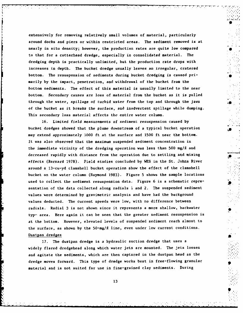
effects (Barnard 1978). Field studies concluded by WES in the St. Johns River . .
around a 13-cu-yd clamshell bucket operation show the effect of the clamshell
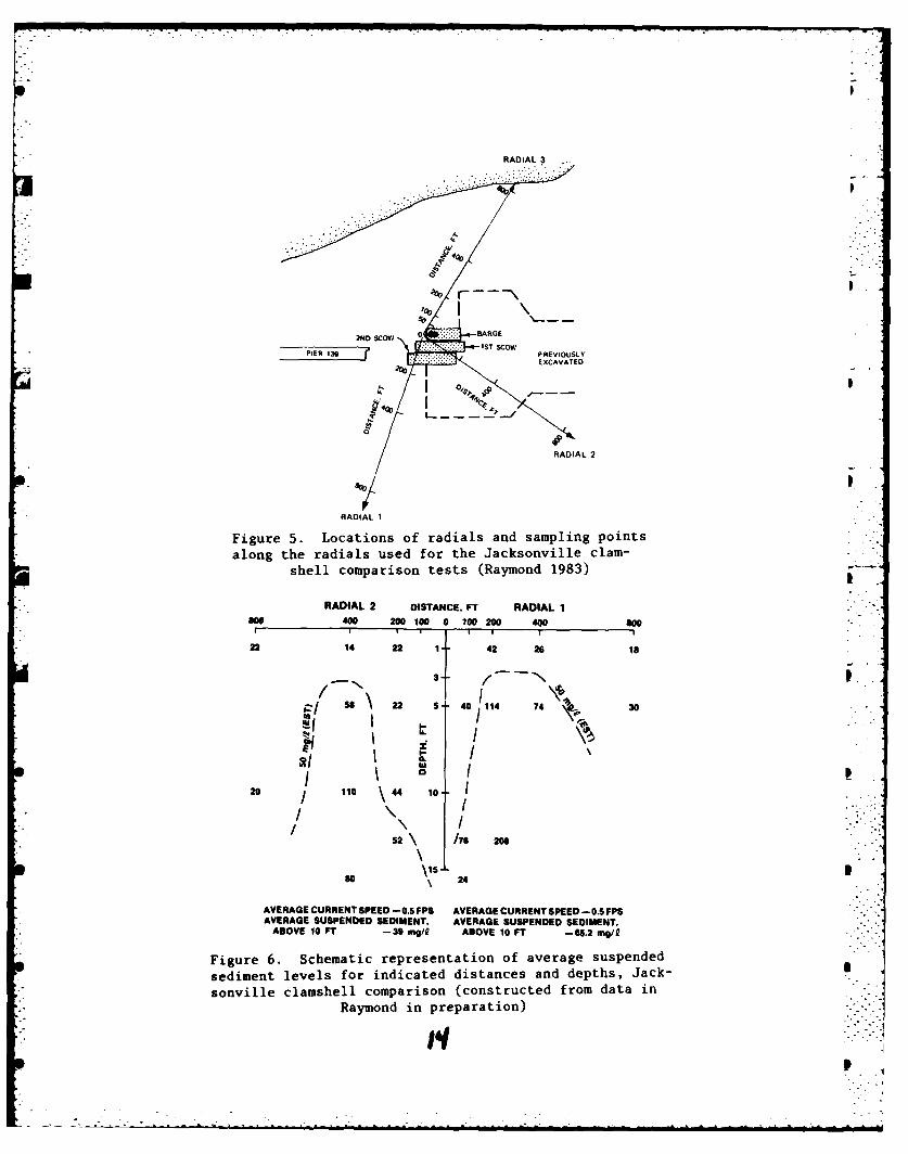
bucket on the water column (Raymond 1983). Figure 5 shows the sample locations
used to collect the sediment resuspension data. Figure 6 is a schematic repre-
sentation of the data collected along radials I and 2. The suspended sediment
values were determined by gravimetric analysis and have had the background
values deducted. The current speeds were low, with no difference between
radials. Radial 3 is not shown since it represents a more shallow, backwater
typp area. Here again it can be seen that the greater sediment resuspension is
at the bottom. However, elevated levels of suspended sediment reach almost to
the surface, as shown by the 50-mg/f line, even under low current conditions.
Dustpan dredges
17. The dustpan dredge is a hydraulic suction dredge that uses a
widely flared dredgehead along which water jets are mounted. The jets loosen
and agitate the sediments, which are then captured in the dustpan head as the
dredge moves forward. This type of dredge works best in free-flowing granular
material and is not suited for use in fine-grained clay sediments. During
13
9
RADIAL 3
Figure 5. Locations of radials and sampling points .~~• along the radials used for the Jacksonville clam-~shell comparison tests (Raymond 1983)
RADIAL 2 DISTANCE, Fr RADIAL 1 .
00400 200100 0 10020 400 0
22 14 22 42 26 18
22D S COW4 7 BAR
I T
PI1 3 PREIO1L
20 i 110 10 o I .
\ ... .:,
RAIA I
/52 \ /76 206."
AVERAGE CURRENT SPEED -0.5 FPS AVERAGE CURRENT SPEED -0.5 FPS i -[
AVERAGE SUSPENDED SEDIMENT. AVERAGE SUSPENDED SEDIMENT, •,•ASOVE 10 FT -30 ms/i ABOVE 10 FT -65.2 mag/0 ..
Figure 6. Schematic representation of average suspendedsediment levels for indicated distances and depths, Jack-
sonville clamshell comparison (constructed from data in i"" ~~Raymond in preparation) .. !
! p
RADIL 2 ISTACE, T RAIAL
goo 00 20 10 a 00 00 40 W
22 14 22 42 26 is

1982, an experiment was conducted in the fine-grained sediments of the James
River using a modified dustpan head (without water jets). The dustpan head
and a conventional cutterhead were operated in the same reach of the James •
River for comparison purposes. It was hoped that the dustpan head, using
suction only, could excavate thin layers of contaminated clay sediment with
less resuspension than a cutterhead. However, the dustpan head experienced
repeated clogging and produced at least as much resuspension as a cutterhead
operating in the same material (Raymond 1983).
Comparison of Dredge Resuspension
18. When planning a dredging operation, the project engineer may be
faced with the problem of selecting the best dredge based on the cost and
availability of different dredges, the operating conditions at the project
site, the material to be dredged, the job specifications, and the various S
environmental considerations. Since each dredging/disposal project is site-
specific, a dredge that might be ideal in one situation may not be suitable
for another. The production rate of a given dredge relative to the levels of
turbidity that may be generated, the duration of the project, and the back-
ground levels of suspended sediment and contamination should all be considered
when evaluating the potential impact of different sizes and types of dredges.
19. It is important to remember that a sophisticated and expensive
dredging system will not necessarily eliminate all sediment resuspension.
In addition, it is imperative to concurrently consider the compatibility of
all the phases of the dredging operation (excavation, transportation, and
disposal) as a total, integrated system and not as separate components. The
relative impact of each operation must be objectively evaluated relative to
its cost and overall benefits.
20. The results of field studies may provide some insight into dredge
selection when limiting sediment resuspension is an important factor. Wake-
man, Sustar, and Dickson (1975), based on their work in San Francisco Bay,
state "the cutterhead dredge seems to have the least effect on water qual-
ity during the dredging operation. This is followed by the hopper dredge
without overflow. The clamshell dredge and hopper dredge during overflow
periods both can produce elevated levels of suspended solids in the water
column." Herbich and Brahme (in press), discussing comparisons of the sediment
15

resuspension potential of different dredges operating in clay, found that the
trailing suction dredge (without overflow) and the cutterhead dredge had a
similar resuspension potential, while the clamshell dredge was determined to
produce about two and a half times as much resuspension. Field tests con-
ducted by Raymond (1983) also support this ranking. The following tabulation
was constructed from Raymond's test results and summarizes the effects of a
clamshell bucket dredge and a cutterhead dredge operating in similar fine-
grained sediments.
Resuspended Sediment, mg/IUpper Water
Dredge Type Column Near Bottom S
Cutterhead 34.6 133.5
Clamshell 105.9 134.3
These data were normalized with respect to hydrodynamic conditions and back- p
ground levels of suspended sediment. The values represent the average of all
samples taken within 800 ft of the dredge along similar radials. The tabula-
tion shows that while the effect of the cutterhead and the clamshell are simi-
lar at near-bottom levels (1 to 5 ft from the bottom), the cutterhead's effect
is much less than the clamshell's in the upper water column. This can also be
seen by comparing the 50-mg/I lines shown in Figures 3 and 6. Figure 7 is the
average of the suspended sediment values shown in Figures 3 and 6, with the
clamshell bucket values shown in parentheses. We see that the cutterhead ex-
ceeds 50 mg/i only near the bottom, and its effect is barely detectable above
5 ft. The clamshell bucket effects can be seen up to the surface. Thus, the
clamshell affects a greater portion of the water column to a greater extent
than does the cutterhead.
16
h" . . . - -'. . . . . . .. .' •

DEPT"RANGE
HEAR 2 012 5SURFACE 24), (0)4)(3
(43)HEL (3)
MID-.'.
CUTERTERHEA CLSSEL (40)W(ET
N E A R 1 1 1 1 017BOTTOM
Figure 7. Comparison of average suspended sedimentvalues for a cutterhead operation and a clamshelloperation. Values without parentheses are for thecutterhead; values within parentheses are for the
clamshell
17
PART III: LIMITING SEDIMENT RESUSPENSION
Cutterhead Dredge Operations
21. As pointed out by Barnard (1978) and Huston and Huston (1976), the
sediment resuspended by cutterhead excavation is dependent on the operating
techniques used. Indeed, the cutterhead may be the most sensitive of any
dredge type to changes in operating techniques. Barnard (1978) stated that .
the sediment resuspended by the cutter of a cutterhead dredge apparently in-
creases exponentially as thickness of cut, rate of swing, and cutter rotation
rate increase. Although suspended solids levels around the cutter also in-
crease with increasing rates of production, it is possible to maximize the S
production rate of the dredge without resuspending excessive amounts of bot-
tom sediment. Herbich and Brahme (in press), reporting on Japanese studies,
also identify the cutter's revolutions per minute, swing speed, and thickness
of material cut as important factors in determining the level of sediment .
resuspension.
22. Although many researchers have commented on the importance of these
operating factors, few have tried to quantify them. Yagi et al. (1975) and
Shiba and Koba (in press) felt that increasing the depth of cut would also lot
increase the sediment resuspension. However, efficiency experiments (i.e.,
energy required to produce a given output) conducted by Slotta, Joanknecht,
and Emrich (1977) showed that the greatest production and efficiency came from
deeper, rather than shallow cuts (a 45-deg ladder depression versus a 20-deg p
ladder depression for the same depth). Yagi et al. (1975); Shiba and Koba (in
press); and Kaneko, Watari, and Aritomi (in press) all found that the greater
the swing speed, the greater the sediment resuspension. They found this par-
ticularly to be true of swing speeds above 0.5 fps. Slotta, Joanknecht, and
Emrich (1977) found the most efficient swing speed to be 0.3 fps. Finally,
all of the above authors found cutter revolutions per minute (cutter speed) to
be a factor; however, only Shiba and Koba, based on their testing, stated that
this was the major factor. None of the authors attempted to quantify a mini- g
mum cutter speed; however, Slotta, Joanknecht, and Emrich did find that a cut-
* ter speed of 30 revolutions per minute was the most efficient. Finally, both
Yagi et al. (1975) and Kaneko, Watari, and Aritomi (in press) reported that by ..
using the suction without rotating the cutter, resuspension could be reduced pby about one half.
18
,.. J
Operational controls
23. Based on the impact of the factors described above, Huston and
Huston (1976) recommend the following operational controls to limit levels -
of sediment resuspension. These controls will reduce the amount of material ,
disturbed by the cutterhead but not entrained by the suction:
a. Large sets and very thick cuts should be avoided since theytend to bury the cutterhead and may cause high levels of re-suspension if the suction cannot pick up all of the dislodgedmaterial.
b. The leverman should swing the dredge so that the cutterheadwill cover as much of the bottom as possible. This minimizesthe formation of windrows or ridges of partially disturbedmaterial between the cuts; these windrows tend to slough intothe cuts and the material in the windrows may be susceptibleto resuspension by ambient currents and turbulence caused bythe cutterhead. Windrow formation can be eliminated by swing-ing the dredge in close concentric arcs over the dredging area.This may involve either modifying the basic stepping methodsused to advance the dredge or using a Wagger or spud carriagesystem.
c. Side slopes of channels are usually dredged by making a verti-cal box cut; the material on the upper half of the cut thensloughs to the specified slope with associated resuspension.The specified slope should be cut by making a series ofsmaller boxes. This method, called "stepping" the slope,will not eliminate all sloughing, but will help to reduce it.
d. On some dredging projects, it may be more economical toroughly cut and remove most of the material, leaving a rela-tively thin layer for final cleanup after the project has beenroughed out. However, this remaining material may be subjectto resuspension by ambient currents or prop wash from passingship traffic.
e. When layer cutting is used, the dredge will remove a singlelayer of material over a large portion of the channel; thedredge is then set back to dredge another layer. This contin-ues down to the required depth of the project. Since loosematerial is often left on the bottom after each layer isdredged, this technique should only be used where resuspensionof the remaining material will not create sediment resuspen-sion problems.
Equipment design considerations
24. Design of the cutterhead greatly influences the dredge's produc- -
tion and sediment resuspension during the dredging process. The dredge's
suction (Figure 2), which picks up the material that has been cut by the cut-
ter, can be partially responsible for sediment resuspension around the cutter
if the energy provided to the suction by the dredge pump is not great enough
19

to cause the suction to pick up all of the material disturbed by the cutter.
Water-jet booster systems or ladder-mounted submerged pumps installed on
cutterhead dredges have been found to enhance the dredge's pickup capability, . ..
increase slurry density and potential production rate, and decrease the gener-
ation of suspended solids (Barnard 1978).
25. The shape of the cutterhead also affects the sediment resuspended,
particularly if no overdepth is allowed. The cutterheads shown in Figure 80
.0
CONVENTIONAL CUTTERHEAD CONICAL CUTTERHEAD
Figure 8. Effect of cutterhead shape on suction height above the bottom
have the same length and base width. They are also depressed to the same
angle and are buried to the same depth. However, with the conical-shaped
head, the suction is brought closer to the material and the chance of entrain-
ment by the suction is improved. This shape difference would be particularly
important if the head was not completely buried.*
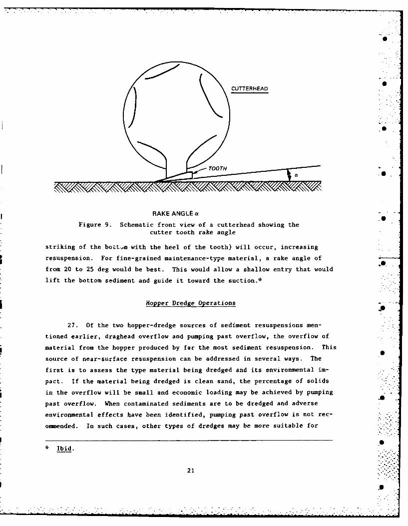
26. The angle a in Figure 9 is called the rake angle. If the rake
angle is too large, it will cause a gouging action that will sling soft
fine-grained material outward. If the rake angle is too small, heeling (the _
* Personal communication from Thomas M. Turner, Turner Consulting, Inc.,Sarasota, Fla., March 1983. Mr. Turner also provided sketches for Figures 8and 9. See also WES Environmental Laboratory files (WESEE) Memorandum forRecord, 15 April 1983, Subject: Equipment Aspects of Dredging ContaminatedSediments.
20 -S. -.
0
CUTTERHEAD .
RAKE ANGLE a
Figure 9. Schematic front view of a cutterhead showing thecutter tooth rake angle
striking of the bot-.,gm with the heel of the tooth) will occur, increasing
resuspension. For fine-grained maintenance-type material, a rake angle of
from 20 to 25 deg would be best. This would allow a shallow entry that would
lift the bottom sediment and guide it toward the suction.*
Hopper Dredge Operations .
27. Of the two hopper-dredge sources of sediment resuspensions men-
tioned earlier, draghead overflow and pumping past overflow, the overflow of
material from the hopper produced by far the most sediment resuspension. This
source of near-surface resuspension can be addressed in several ways. The
first is to assess the type material being dredged and its environmental im-
pact. If the material being dredged is clean sand, the percentage of solids
in the overflow will be small and economic loading may be achieved by pumping
past overflow. When contaminated sediments are to be dredged and adverse
environmental effects have been identified, pumping past overflow is not rec-
ommended. In such cases, other types of dredges may be more suitable for .
*Ibid.
21
- .S °
. . .

removing the contaminated sediments from the channel prism. In the case of
fine-grained materials, the settling properties of silt and clay sediments
may be such that only a minimal load increase would be achieved by pumping
past overflow (Headquarters, Department of the Army (HQDA) 1983).
28. Another approach has been suggested by the Japanese. They have
developed a relatively simple submerged discharge system for hopper dredge
overflow, called the Anti-Turbidity Overflow System (ATOS) (Herbich and Brahme
in press). The overflow collection system in the dredge was streamlined to
minimize incorporation of air bubbles, and the overflow chutes were moved
from the sides to the bottom of the dredge's hull (Figure 10). With this
arrangement, the discharge descends rapidly to the bottom with a minimum
amount of dispersion within the water column. The system can be incorporated
in existing dredges through modifications of their overflow systems. This
system has been suzcessfully incorporated in three Japanese trailing-hopper
dredges with capacities ranging from 2500 to 5000 cu yd. Tests carried out on
SHOPPER -'
OVERFLOWWEIR/INLIE HYDRAULICINCLINED vCYLINDER .
BAFFLE
OVERFLOWTROUGH-
r-- 1 P1 .FLOWOF -.-.. REGULATING ..
70W L.
O VERFL OW CHUTE "77.:1
--
Figure 10. Schematic drawing of a hopper dredgebin equipped with the Japanese designed Anti-Turbidity Overflow System (ATOS) (Herbich and 0
Brahme in press)
22
0

the dredge KAIRYU MARU indicated considerable reduction in sediment resuspen-
sion at the surface and 3 ft below the surface both beside the ship and 100 ft
behind the ship. The data comparing the sediment resuspended by a conven- --S
tional overflow system and by the ATOS are shown below:
Average Concentration ofSuspended Solids, mg/£
Conventional System ATOS3 ft below 3 ft below
Sampling Location Surface Surface Surface Surface
Beside ship 627 272 6.0 8.0
100 ft aft of ship 119 110 6.5 8.9
It should be pointed out, however, that ATOS is intended only to reduce near-
surface suspended solids, not the overall amount of suspended solids in the
water column. The ATOS device has the effect of forcing the solids plume
down to a lower level. This in itself can have the effect of limiting the
areal extent of the resuspended solids.
Clamshell Bucket Dredge Operations
29. Although Japanese experimenters have reported some reduction in
sediment resuspension with the variation of hoist speed and depth of cut,
their greatest reduction in resuspension with clamshell dredging came from
the use of a so-called "watertight" or enclosed clamshell bucket. The Port
and Harbor Institute of Japan developed a watertight bucket in which the
top is enclosed so that the dredged material is contained within the bucket.
A direct comparison of a 1-cu-m standard open clamshell bucket with a water-
tight clamshell bucket indicates that watertight buckets generate 30 to
70 percent less resuspension in the water column than the open buckets
(Barnard 1978).
30. A field test to compare the effectiveness of enclosed clamshell
buckets was conducted by WES. The resuspension produced by an enclosed
13-cu-yd bucket was compared to a 12-cu-yd standard open bucket during dredg-
ing of the St. Johns River near Jacksonville, Fla. The results of this test
are given in the tabulation on the following page.
2
23.. .
. . . . • . •

Average Suspended SedimentType of Level, mg/f*
Clamshell Sampling Upper NearBucket Radial Water Column Bottom**
Enclosed 1 27 233
2 36 300
3 81 N/At
Open 1 123 147
2 61 122
3 133 N/At
Average of all samples taken along the radial, adjusted for background
suspended sediment level.** Measurements made within 5 ft of bottom.
t Average depth along this radial is 5 ft or less.
The sampling locations and radials used in this test were shown in Figure 5.
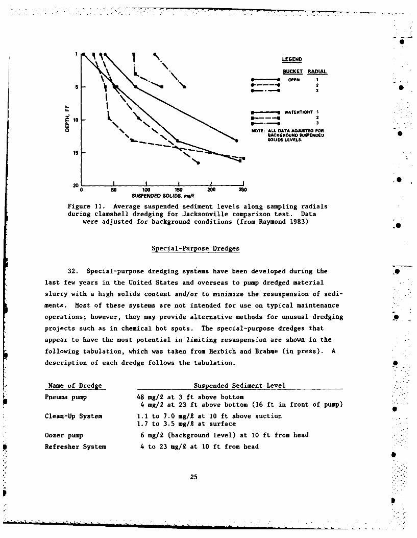
Figure 11 shows the average suspended sediment levels at increasing depths
along each radial. This test revealed a reduction in sediment resuspension
in the upper water column with the enclosed bucket (Raymond 1983). Some draw- p
backs were also revealed however. The enclosed bucket produced increased
resuspension near the bottom, probably due to a shock wave of water that pre-
cedes the watertight bucket due to the enclosed top. Also both the earlier
Japanese and the Jacksonville buckets had rubber gaskets for seals along the
cutting edge of the bucket. This limited the use of the bucket to soft
material and trash-free areas. Current design concepts include the use of
an interlocking tongue-and-groove edge to overcome the sealing problems.
31. Operationally, clamshell bucket resuspension can be lessened by en-
suring the operator does not "drop" the bucket into the sediment but allows it
to settle under its own weight, and by avoiding "sweeping." Sweeping is where
the bucket is swung across the width of the cut to smooth the bottom and level
off the high points. Sweeping occurs at the end of the cut prior to advancing
to a new cut. Sweeping does help to level the irregular bottom that results
from clamshell dredging; however, it also contributes significantly to sediment
resuspension and should not be allowed when dredging contaminated sediments.
2
24 --
.... -
1 1 \.LEGEND
1.BUCKET RADIAL
0 ---..-- OPEN I5 2
3S
i *L.. WATERTIGHT I3e.- -- § 2
NOTE: ALL DATA ADJUSTED FORBACKGROUND SUSPENDED
15 SOLIDS LEVELS.
20 I I I , I0 so 100 150 200 250
SUSPENDED SOLIDS, mf/9
Figure 11. Average suspended sediment levels along sampling radialsduring clamshell dredging for Jacksonville comparison test. Data
were adjusted for background conditions (from Raymond 1983)
Special-Purpose Dredges
32. Special-purpose dredging systems have been developed during the
last few years in the United States and overseas to pump dredged material
slurry with a high solids content and/or to minimize the resuspension of sedi-
ments. Host of these systems are not intended for use on typical maintenance
operations; however, they may provide alternative methods for unusual dredging
projects such as in chemical hot spots. The special-purpose dredges that
appear to have the most potential in limiting resuspension are shown in the
following tabulation, which was taken from Herbich and Brahme (in press). A
description of each dredge follows the tabulation. 0
Name of Dredge Suspended Sediment Level
Pneuma pump 48 mg/2 at 3 ft above bottom4 mg/£ at 23 ft above bottom (16 ft in front of pump)
Clean-Up System 1.i to 7.0 mg/k at 10 ft above suction1.7 to 3.5 mg/1 at surface
Oozer pump 6 mg/2 (background level) at 10 ft from head
Refresher System 4 to 23 mg/1 at 10 ft from head
2
25|
. .. . . . . ..-I .
,-* " -. 7
Pneuma pump
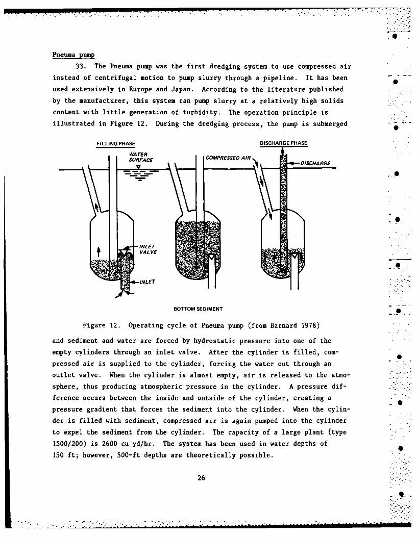
33. The Pneuma pump was the first dredging system to use compressed air
instead of centrifugal motion to pump slurry through a pipeline. It has been -
used extensively in Europe and Japan. According to the literature published
by the manufacturer, this system can pump slurry at a relatively high solids
content with little generation of turbidity. The operation principle is
illustrated in Figure 12. During the dredging process, the pump is submerged - -
FILLING PHASE DISCHARGE PHASE
WA TERSURFACE COMPRESSED AIR DISCHARGE
INLET .
VALVE : . , . 'lINLET
BOTTOM SEDIMENT
Figure 12. Operating cycle of Pneuma pump (from Barnard 1978)
and sediment and water are forced by hydrostatic pressure into one of the
empty cylinders through an inlet valve. After the cylinder is filled, com-
pressed air is supplied to the cylinder, forcing the water out through an
outlet valve. When the cylinder is almost empty, air is released to the atmo-
sphere, thus producing atmospheric pressure in the cylinder. A pressure dif- "
ference occurs between the inside and outside of the cylinder, creating a
pressure gradient that forces the sediment into the cylinder. When the cylin-
der is filled with sediment, compressed air is again pumped into the cylinder
to expel the sediment from the cylinder. The capacity of a large plant (type
1500/200) is 2600 cu yd/hr. The system has been used in water depths of 0150 ft; however, 500-ft depths are theoretically possible.
26
......- . . .,........
34. Field tests on a Pneuma model 600/100 were conducted by WES
(Richardson et al. 1982). The results of turbidity monitoring, although not
definitive, seemed to support the manufacturer's claim that the Pneuma pump
generates a low level of turbidity when operated in loosely consolidated fine- 0
grained sediments. It was also found that the Pneuma pump was able to dredge
at almost in situ density in a loosely compacted silty clay typical of many
estuarine sediments. The Pneuma pump, however, was not able to dredge sand at
in situ density.
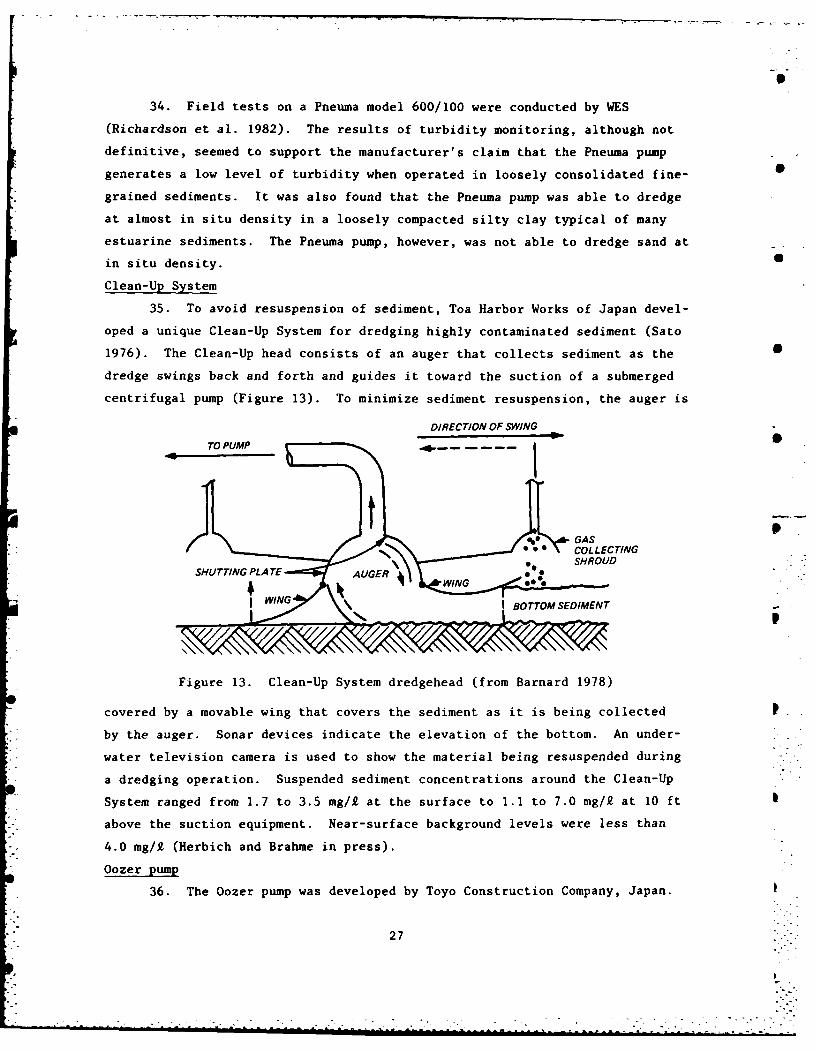
Clean-Up System
35. To avoid resuspension of sediment, Toa Harbor Works of Japan devel-
oped a unique Clean-Up System for dredging highly contaminated sediment (Sato
1976). The Clean-Up head consists of an auger that collects sediment as the 0
dredge swings back and forth and guides it toward the suction of a submerged
centrifugal pump (Figure 13). To minimize sediment resuspension, the auger is
DIRECTION OF SWING
TO PUMP
e GAS
06 COLLECTINGSHROUD "
IWIN
WING I BOTTOM SEDIMENT
\I
Figure 13. Clean-Up System dredgehead (from Barnard 1978)
covered by a movable wing that covers the sediment as it is being collected
by the auger. Sonar devices indicate the elevation of the bottom. An under-
water television camera is used to show the material being resuspended during
a dredging operation. Suspended sediment concentrations around the Clean-Up
System ranged from 1.7 to 3.5 mg/i at the surface to 1.1 to 7.0 mg/k at 10 ft
above the suction equipment. Near-surface background levels were less than
4.0 mg/i (Herbich and Brahme in press).
Oozer pump
36. The Oozer pump was developed by Toyo Construction Company, Japan.
27

The pump operates in a manner similar to the Pneuma pump system; however,
there are two cylinders (instead of three) and a vacuum is applied during the
cylinder-filling stage to achieve more rapid filling of the cylinders. The
pump is usually mounted on a dredge ladder and is equipped with special suc-
tion and cutterheads depending on the type of material being dredged. The
conditions around the dredging system, such as the thickness of the sediment
being dredged, the bottom elevation after dredging, and the amount of resus-
pension, are monitored by high-frequency acoustic sensors and an underwater
television camera. A large Oozer pump has a dredging capacity ranging from
400 to 650 cu yd/hr. During one dredging operation, suspended solids levels
within 10 ft of the dredging head were all within background concentrations of
less than 6 mg/I (Herbich and Braime in press).
Refresher System
37. Another system designed recently by the Japanese is the Refresher
System. This system is an effort to modify the cutterhead hydraulic dredge.
The Refresher uses a helical-shaped gather head to feed the sediments into the
suction, with a cover over the head to reduce resuspension (see Figure 14).
The Refresher also uses an articulated dredge ladder to keep the head level
with the bottom over a wide range of dredging depths. During several tests
in similar material, the Refresher System produced suspended sediment levels
of from 4 to 23 mg/£ within 10 ft of the dredge head as compared to 200 mg/-
with a conventional cutterhead dredge. Production for the cutterhead (26-in.
discharge) was 800 cu yd/hr while production with the Refresher System (17-in.
discharge) was 350 cu yd/hr. The researchers felt that the Refresher System
produced one fiftieth of the total resuspension produced by the operation of a
cutterhead dredge (Kaneko, Watari, and Aritomi in press).
.-.
. . ..
28 ----- --
-------- --

UNDERWATER
00
HYDRAULICCYLINDERSUCTION CONTROL PLATE
GAS COLLECTOR
.RUBBER PLATE SIGDIETO
a. Front view .
UNDER WA TER TV CAMERA
TURB DISE SOR O NI M PLA
COVER
b. Side view
Figure 14. Front and side view of Japanese Refresher System(from Kaneko, Watari, and Aritomi in press)
29
I-

PART IV: CONCLUSIONS AND RECOMMENDATIONS
Conclusions 0
38. Based on the results of the ongoing research, the following conclu-
sions can be drawn:
a. Dredging can cause the resuspension of contaminated sediments 0from the bottom into the water column. The sediments mostlikely to remain resuspended during a dredging operation--fine-grained, clay-sized, and organic particles--are the ones thatshow the greatest affinity for chemical contaminants of varioustypes. Dredging operations conducted in coarser sedimentsshould experience little difficulty with resuspension orcontamination.
b. Different dredge types produce different amounts of suspendedsediment in different parts of the water column. The cutter-head produces most of its resuspension near the bottom, as does -
the hopper dredge without overflow. The bucket dredge andhopper dredge with overflow produce suspended sediments through-out the water column. Sediments resuspended in the upper watercolumn are of particular concern since a greater potential forsuspended sediment dispersal exists in the upper water column.
c. Sediment resuspension can be lessened by changing operatingtechniques or by modifying the equipment. Many researcherssuggest that controlling cutter rotation speed, swing speed, ...
and depth of cut of a cutterhead dredge can reduce sedimentresuspension. In fact, any operating technique that improvesthe production of the cutterhead dredge will probably reduceresuspension. Hopper and bucket dredges will probably requiresome equipment modification to achieve a meaningful reductionin sediment resuspension.
d. A wide variety of special-purpose dredges are available thatappear to substantially reduce the potential for resuspensionof sediment. However, most of these dredges have low produc-tion rates, and more research is needed to evaluate their areasof application and their limitations.
Recommendations
39. Although additional research is being conducted to further quantify
the effects of the equipment and operational modifications discussed in this
paper, it is recommended that:
a. A cutterhead dredge be considered whenever possible to limitresuspension. If properly operated, the cutterhead appears toproduce the least resuspension of conventional equipment.
30
.................................
b. When it is necessary to use a bucket dredge, it should be en-closed to reduce resuspension.
c. Hopper dredges in general should not be used when sedimentresuspension is a concern. If a hopper must be used, it shouldnot be allowed to pump past overflow.
40. It is further recommended that, in addition to further field tests
of conventional dredges, the testing of special-purpose dredge elements be
conducted. This testing may require the purchase or construction of a special-
purpose dredge for evaluation purposes.
•
0
31-""

L
REFERENCES
Barnard, W. D. 1978. "Prediction and Control of Dredged Material DispersionAround Dredging and Open-Water Pipeline Disposal Operation," Technical Re-port DS-78-13, U. S. Army Engineer Waterways Experiment Station, CE, Vicks-burg, Miss.
Thilk, R., Gruber, D., and Wullschleger, R. 1975. "Laboratory Study of theRelease of Pesticides and PCB Materials to the Water Column During DredgingOperations," Contract Report D-75-6, U. S. Army Engineer Waterways ExperimentStation, CE, Vicksburg, Miss.
Headquarters, Department of the Army (HQDA). 1983. "Dredging and DredgedMaterial Disposal," Engineer Manual EM 1110-2-5025, Washington, D. C.
Herbich, J. B., and Brahme, S. B. In press. "A Literature Review and Tech- Snical Evaluation of Sediment Resuspension During Dredging," U. S. Army Engi-neer Waterways Experiment Station, CE, Vicksburg, Miss.
Huston, J. W., and Huston, W. C. 1976. "Techniques for Reducing TurbidityAssociated with Present Dredging Procedures and Operations," Contract Report D-76-4, U. S. Army Engineer Waterways Experiment Station, CE, Vicksburg, Miss.
Kaneko, A., Watari, Y., and Aritomi, N. In press. "The Specialized DredgesDesigned for the Bottom Sediment Dredging," Proceeding of the 8th U. S.,Japan Experts Conference on Toxic Bottom Sediments, Tokyo, Japan, Novem-,ber 1982, U. S. Army Engineer Water Resources Support Center, Ft. Belvoir, Va.
Raymond, G. L. 1983. "Field Study of the Sediment Resuspension Character-istics of Selected Dredges," Proceedings of the 15th Annual Texas A&N Dredg-ing Seminar, New Orleans, La., Texas A&M University, College Station, Tex.
Raymond, G. L. In preparation. "Investigations of the Sediment ResuspensionCharacteristics of Conventional Dredges," U. S. Army Engineer WaterwaysExperiment Station, CE, Vicksburg, Miss.
Richardson, T. W., et al. 1982. "Pumping Performance and Turbidity Generationof Model 600/100 Pneuma Pump," Technical Report HL-82-8, U. S. Army EngineerWaterways Experiment Station, CE, Vicksburg, Miss.
Sato, E. 1976. "Application of Dredging Techniques for Environmental Prob-lems," Proceedings of WODCON VII: Dredging, Environmental Effects and 4
Technology. S
Shiba, T., and Koba, H. In press. "Sediment Resuspension in the Vicinity ofthe Cutterhead," Proceedings of the 8th U. S./Japanese Experts Conference onToxic Bottom Sediments, Tokyo, Japan, November 1982, U. S. Army Engineer WaterResources Support Center, Ft. Belvoir, Va.
Slotta, L. S., Joanknecht, L. W. F., and Emrich, R. K. 1977. "Influence of - SCutterhead Height on Dredge Production," Proceeding of Second InternationalSymposium on Dredging Technology, BHRA-Fluid Engineering, Cranfield, Bedford,England.
Wakeman, T. H., Sustar, J. F., and Dickson, W. J. 1975. "Impacts of ThreeDredge Types Compared in San Francisco District," World Dredging and MarineConstruction, Vol 11, No. 3.
32
.- .-. ..-

Wechsler, B. A., and Cogley, D. R. 1977. "A Laboratory Study of the Turbid-ity Generation Potential of Sediments to Be Dredged," Technical Report D-77-14,U. S. Army Engineer Waterways Experiment Station, CE, Vicksburg, Miss.
Yagi, T., et al. 1975. "Effect of Operating Conditions of Hydraulic Dredgeson Dredging Capacity and Turbidity," Technical Note 228, Port and Harbor Re-search Institute, Ministry of Transport, Yokosuka, Japan.
0
3
• .I.2
• .,"I
-. I
.,I'
S
33i: :
L

.4r 4
4Vt jL L4V!47
4~1 T **q
* ,. ftt JP&' g% ,Ali ~