recovered water management study in shale wells - · pdf filemanagement study in shale wells...
TRANSCRIPT

The world’s leading sustainability consultancy
Recovered Water Management Study in Shale Wells Final Report ERM project 0243719
June 2014

Recovered Water Management Study in Shale Wells
Sponsor: International Association of Oil and Gas Producers (OGP)
Prepared By: Environmental Resources Management (ERM)
Final Report ERM project 0243719 June 2014
ERM: Reviewed by: Paola Quijano
Signature:
Title: Project Manager
Date: June 2014
Approved by: María Quintana
Signature:
Title: Partner
Date: June 2014
This report has been prepared by ERM, the trading name of Environmental Resources Management - ERM Iberia, S.A. with all
reasonable skill, care and diligence within the terms of the Contract with the client, incorporating our General Terms and Conditions of Business and taking account of the resources devoted to it by agreement with the
client.
We disclaim any responsibility to the client and others in respect of any matters outside the scope of the above.
This report has been prepared for the client and we accept no
responsibility of whatsoever nature to third parties to whom this report, or any part thereof, is made known. Any such party relies upon the report at
their own risk.

TABLE OF CONTENTS
GLOSSARY
1 EXECUTIVE SUMMARY 4
2 INTRODUCTION 7
2.1 PURPOSE OF THIS STUDY 7 2.2 SCOPE OF THIS STUDY 7 2.3 METHODOLOGY APPLIED 7 2.4 MAIN LIMITATIONS 7 2.5 STRUCTURE OF THE REPORT 8
3 GENERAL DESCRIPTION OF THE HYDRAULIC FRACTURING PROCESS AND RECOVERED WATER QUALITY 9
3.1 OVERVIEW 9 3.2 DESCRIPTION OF THE HYDRAULIC FRACTURING TECHNIQUE 9 3.3 CHARACTERISTICS OF THE HYDRAULIC FRACTURING FLUID 10 3.4 RECOVERED WATER QUALITY 11
4 IDENTIFICATION OF RECOVERED WATER MANAGEMENT OPTIONS 15
4.1 OVERVIEW 15 4.2 IDENTIFICATION OF CURRENT MANAGEMENT PRACTICES PERFORMED GLOBALLY15 4.3 DECISION MAKING PROCESS 19
5 DESCRIPTION OF DISPOSAL / END USE OPTIONS AND TREATMENT TECHNOLOGIES FOR RECOVERED WATER 21
5.1 OVERVIEW 21 5.2 RECOVERED WATER MANAGEMENT PRACTICES AND TREATMENT
TECHNOLOGIES 21 5.3 DESCRIPTION OF DISPOSAL OPTIONS 22 5.4 DESCRIPTION OF REUSE SCENARIOS 34 5.5 SUMMARY OF THE MAIN MANAGEMENT OPTIONS 41 5.6 DESCRIPTION OF TREATMENT TECHNOLOGIES 43
6 FUTURE DEVELOPMENTS IN RECOVERED WATER MANAGEMENT FOR SHALE WELLS 52
6.1 OVERVIEW 52 6.2 FUTURE DEVELOPMENTS 52 6.3 MINIMISATION OF FRESHWATER IN THE HYDRAULIC FRACTURING FLUID 52 6.4 MAXIMISATION OF REUSE 52 6.5 IMPROVEMENT OF TREATMENT TECHNOLOGIES 53
7 CONCLUSIONS 54
8 REFERENCES 56

ERM 1 RECOVERED WATER MANAGEMENT STUDY IN SHALE WELLS
GLOSSARY Definitions of the key terminology used in this study:
• By-products: residues generated during the treatment of recovered water. By-products may have different names and forms (e.g., slurry, sludge, and backwash) depending on the specific process that generated them. They may also have similar contents according to the type of constituents treated.
• Disposal (management practice): a recovered water management practice where treated water exits the hydraulic fracturing operation and is not subsequently used in the operation. Treated recovered water is returned to the hydrological cycle (e.g., discharged into a surface water body, evaporated into the atmosphere, or injected into a deep saline aquifer).
• Drilling fluid: this fluid (often referred to as “mud”) is usually a mixture of water, clay, weighing material and chemicals that is used to raise rock cuttings, made by the drill bit during the perforation of vertical/horizontal wells, to the surface for disposal.
• Exploration and appraisal phase: exploration typically involves the acquisition and interpretation of geological data from the potential hydrocarbon layers of interest. As part of this acquisition process, operators may decide to drill wells that are designed for logging and taking core samples to obtain further geological data on the formation. Following the data appraisal, operators may then decide to flow test the well before making any further commercial decisions. This stage may also involve carrying out hydraulic fracturing procedures, depending on the geology. The information gathered during this relatively short phase helps the operators evaluate parameters such as expected flow rates and well performance, in order to better define subsequent development phase requirements and commercial viability.
• Flowback water: the water that returns to the surface from the wellbore within the first months after hydraulic fracturing. Flowback water is primarily composed of fracturing fluids and sand (or other material used as proppant in the process). It may also contain some water from the formation.
• Fracturing fluid: fluid used to stimulate the target formation during hydraulic fracturing. It is comprised of a base liquid, a selection of additives and a proppant agent, most commonly sand. In the early days of hydraulic fracturing, freshwater was generally considered to be the only option for use as base fluid, given that the type of additives used at that time were not compatible with highly saline water. Through time, research into additives has resulted in the creation of new compounds that are capable of maintaining their properties under a broad spectrum of water quality conditions. These additives maximise the potential for recovered (or brackish) water to be used in the preparation of fracturing fluid for subsequent fracturing/drilling operations.

ERM 2 RECOVERED WATER MANAGEMENT STUDY IN SHALE WELLS
• Groundwater: as defined by the U.S. Ground Water Protection Council, groundwater refers to water contained in geological media which has been designated by a state as usable for domestic, industrial or municipal purposes1.
• Hydraulic fracturing: a technique that is used by the oil and gas industry to stimulate a specific target formation that would otherwise not produce at economic rates. Fracturing is used in some hydrocarbon-bearing rocks with low permeability, such as shale, after the drilling process. The technique consists of pumping a highly pressurised fluid, primarily water containing a propping agent (“proppant”), such as sand, down the wellbore and into the formation, to create an extensive network of fractures in the hydrocarbon-bearing rock. The proppant holds the fractures open allowing fluids to be produced from the reservoir formations.
• NORM: an acronym for Naturally Occurring Radioactive Materials, which include radioactive elements found in the environment such as uranium, thorium and potassium, and any of their radioactive decay products, such as radium and radon. These elements have always been present in the earth’s crust and within the tissues of all living beings.
• Pilot and development phase: this is based on the results of the exploration and appraisal phase and is operator’s plan for the full development of the field, including the construction and operation of processing facilities, pipelines, and drilling and stimulation of wells in the areas where the oil and gas will be commercially extracted. The step before full development is a pilot project which involves the same components as full development but on a smaller scale. This helps the operator refine the design for the development. The main characteristic of a development phase is the permanency of facilities as it is associated with long term operation.
• Produced formation water: water that exists in subsurface formations (also known as formation water) and is brought to the surface during oil and gas extraction. Usually this water is known as produced water.
• Proppant: A granular substance, often sand, that is mixed with and carried by fracturing fluid pumped into a shale well. Its purpose is to keep cracks and fractures that occur during the hydraulic fracturing process open so trapped natural gas can escape
• Recovered water: a combination of flowback and produced water that returns to the surface from the wellbore after hydraulic fracturing.
• Reuse (management practice): a recovered water management practice where the treated recovered water is subsequently used in either hydraulic fracturing activities or other industrial processes.
1 1 According to the Water Framework Directive (DIRECTIVE 2000/60/EC) - Article 2: groundwater means all water which is below the surface of the ground in the saturation zone and in direct contact with the ground or subsoil. The main difference between this definition and the definition that will be used in this study is that the latter refers to water usage as a criterion to define the concept of groundwater.

ERM 3 RECOVERED WATER MANAGEMENT STUDY IN SHALE WELLS
• Shale formation: shale is a fine-grained sedimentary rock that forms from the compaction of silt and clay-size mineral particles and has a fissile (readily splitting) and laminated (made of thin layers) texture. A shale formation is an extension of this type of material that is sufficiently distinct from other surrounding geological layers to be differentiated. Most shale formations are considered source rock reservoirs for other traditional hydrocarbon reservoirs.
• Shale Gas Play: A set of discovered, undiscovered or possible natural gas accumulations that exhibit similar geological characteristics. Shale plays are located within basins, which are large-scale geologic depressions, often hundreds of miles across, which also may contain other oil and natural gas resources

ERM 4 RECOVERED WATER MANAGEMENT STUDY IN SHALE WELLS
1 EXECUTIVE SUMMARY
Hydraulic fracturing is a well stimulation technique that has been used in the oil and gas industry for the past 65 years to improve production from hydrocarbon containing formations. It is not exclusive to shale formations. However, because of the very low to nonporous characteristics of shale formations, hydraulic fracturing is always required as part of the oil and gas extraction.
After a shale well has been hydraulically fractured, produced and flowback water returns to the surface inside a steel pipe. For the scope of this study, all fluids (including flowback and produced water) that flow back to the surface in the first weeks to months after the fracturing of a shale well, are considered to be recovered water.
Water management is a key consideration throughout all the stages of shale play development, from an early exploration phase where only a handful of wells are stimulated to a mature development phase where there may be hundreds of wells stimulated.
A basic water management cycle showing the identified management practices is presented in Figure 1.1.
Figure 1.1 Water cycle overview with identified management practices
Source: prepared by ERM, 2014
This report covers only one key aspect of the entire water management cycle in shale operations: the management practices adopted in regard to the recovered water that exits from a shale oil/gas well following stimulation.
Other aspects of the water management cycle, such as the sourcing of water transport and storage, as well as related issues, such as availability and demand by other users, are not included in this report.
Shale plays differ widely in their geological characteristics (depth, thickness, total porosity, mineral and hydrocarbon content). The volume of water recovered after hydraulic fracturing varies in terms of quantity (e.g., volume)

ERM 5 RECOVERED WATER MANAGEMENT STUDY IN SHALE WELLS
and quality (e.g., concentration of heavy metals, salinity, and radionuclides), and depends a great deal on the geology of the particular shale play.
There are several proven methods for handling recovered water that have been used successfully by the industry over the past decades. The features of specific practice may vary greatly between shale plays. The final decision on which recovered water management practice to apply to a shale well is subject to a number of site-specific conditions including, but not limited to, the characteristics of the formation, existing available management options, the phase of the operations (e.g., exploration versus development), the regulatory framework, and the environmental and social conditions in the area.
Two broad management practice categories have been identified for effectively handling the recovered water once it reaches the surface: disposal and reuse. The main difference between these practices is the final end use of the recovered water. Particular management scenarios have been identified for both of these categories, as represented in Figure 1.2. Based on the management option and scenario selected, a fit-for-purpose treatment train must be designed to achieve the target parameters required for the water before its final disposal or reuse.
Figure 1.2 Current Recovered Water Management Practices in Shale Wells
Source: Prepared by ERM, 2014
If the disposal management option is selected, the recovered water will not subsequently be used in the shale operation. Within this option, three possible scenarios have been identified: i) discharge, where treated recovered water is usually sent to a surface water body; ii) evaporation, where treated recovered water evaporates into the atmosphere; and iii) underground injection, where treated recovered water is injected into a deep underground aquifer.
For the reuse option, two scenarios have been identified: i) reuse within the same shale operation as fracturing/drilling fluid, after undergoing variable levels of treatment (from basic to intermediate); and ii) reuse in other processes after undergoing advanced desalination treatment.
Within a single water management practice, various factors may affect otherwise equivalent scenarios. These include the choice of particular water treatment technologies, the availability of third party services and

ERM 6 RECOVERED WATER MANAGEMENT STUDY IN SHALE WELLS
infrastructure in the area, and the need to transport recovered water. For this reason, two individual scenarios of the same type may differ considerably in cost.
Treatment technologies vary considerably according to the target constituent(s), their underlying physical/chemical process (which mainly determines energy-input requirements), and the resultant by-product of the treatment.
From a global perspective, the majority of management practices employed are currently the disposal type (i.e., underground injection). Even so, there is a growing trend towards reuse practices, given current water supply constraints in certain areas and the limited availability of disposal wells, as this indirectly influences the running costs of an operation. The use of disposal wells is amongst the most cost-effective options, it is widely used in conventional plays, and has a low environmental impact when properly managed. For these reasons it is widespread in countries where shale activities are just starting up (e.g., China, Argentina, and Mexico), as well as in countries where a mature shale market exists (e.g., the United States).
Reuse scenarios are gradually becoming more popular, especially in the United States where more than 80% of the world’s shale extraction is performed. These scenarios make more sense when used in large-scale shale development activities where there are many wells to be fractured. Also, water constraints and a lack of available underground disposal facilities further drives operators towards reuse practices as part of their water management strategy.
Considering the existing challenges for recovered water management in shale wells, three main focus areas for future developments have been identified:
• Minimisation of water volumes required in the fracturing fluid;
• Maximisation of reuse; and
• Improvement of treatment technologies.
In summary, there is no fit-all management practice/scenario that can be applied to every social, environmental, operational and/or economic setting. Management practices differ in every case and are selected based on the intended use for the recovered water.
The water management scenarios identified also have associated environmental impacts due to the various activities involved in a particular scenario. Nonetheless, since all of the management practices identified are proven and have been in use for many years, applying existing industry standards makes these practices environmentally safe when they are managed correctly.

ERM 7 RECOVERED WATER MANAGEMENT STUDY IN SHALE WELLS
2 INTRODUCTION
2.1 PURPOSE OF THIS STUDY
Environmental Resources Management (ERM) has been commissioned by the Oil and Gas Producers Association (OGP) to carry out this study for the purpose of developing a brief review of current and potentially viable recovered water management practices occurring in shale oil/gas wells.
2.2 SCOPE OF THIS STUDY
This report covers only one key aspect of the entire water management cycle in shale operations (Figure 1.1), relating to the management practices adopted in regard to the recovered water that exits from a shale oil/gas well following stimulation.
Other aspects of the water management cycle such as the sourcing of water transport and storage, as well as related issues such as availability and demand by other uses are not included in this report.
2.3 METHODOLOGY APPLIED
The present report is the result of a desktop study based on publicly available information and expert opinions on existing and potentially viable water management practices for recovered water in shale developments around the world. This desktop exercise has been validated and complemented wherever possible with first-hand information provided by different oil and gas operators by means of personal interviews. The operators that participated in this process have provided information on their own field experience in applying the identified management options in different geographies.
Furthermore, ERM has worked in collaboration with Mr. John Veil, an internationally recognised expert in this field, who has provided technical oversight in the development of this document.
2.4 MAIN LIMITATIONS
Due to the nature of the information sources used in this study, the bulk of available resources refer to shale developments in the United States, with relatively little information available on other areas such as Asia and Europe.
It is worth noting that the research focused on the most common current practices; numerous references have been found describing particular management practices in specific locations where these can no longer be considered current practice in shale operations. In view of this, the report strives to keep its findings within a limited and recent time window to properly describe the present state-of-the-art of global water management practices associated with hydraulic fracturing.

ERM 8 RECOVERED WATER MANAGEMENT STUDY IN SHALE WELLS
Water treatment technologies are continuously evolving, driven by the target constituent that poses the biggest challenge for achieving a water of sufficient quality for reuse in the industry or other applications, that is, a high concentration of TDS. There are many versions of similar technologies currently being researched, and this report does not attempt to describe every possible version available, only those considered to be currently available in the marketplace.
2.5 STRUCTURE OF THE REPORT
This report focuses on the different characteristics of the identified water management practices, including: technical functioning, energy use, technical/practical limitations, advantages and disadvantages and the identification and management of the by-products created during the treatment of recovered water. Furthermore, it contains a general description of where the identified practices are used internationally, along with their relative importance in terms of shale gas/oil production, in order to identify which practices are currently the most commonly performed globally.
For completeness, the report describes the characteristics of the liquids involved in the hydraulic fracturing process, beginning with the water source for the base fluid, and describing the various chemical additives which may be mixed with it to form the stimulation fluid. This is followed by a description of how the fluid interacts with the underground shale formation water to ultimately produce a recovered water flow that reaches the surface through the wellbore and which must be properly managed according to various factors including its quality/quantity.
ERM 9 RECOVERED WATER MANAGEMENT STUDY IN SHALE WELLS
3 GENERAL DESCRIPTION OF THE HYDRAULIC FRACTURING PROCESS AND RECOVERED WATER QUALITY
3.1 OVERVIEW
Hydraulic fracturing is a well stimulation technique that has been used in the oil and gas industry for the past 65 years to improve production from hydrocarbon-containing formations. The procedure used depends on the properties of the geological formation where the hydrocarbon deposits are. The technique is not exclusive to shale formations, but their very low to nonporous characteristics mean that hydraulic fracturing is used as part of the oil and gas extraction strategy. The recovered water is a by-product of the hydraulic fracturing technique.
Shale plays differ widely in their geological characteristics (depth, thickness, total porosity, mineral and hydrocarbon content). The geological characteristics of the shale formation at each specific site are key factors influencing both the hydraulic fracturing fluid to be used in the process and the quality of the recovered water associated to the fracturing.
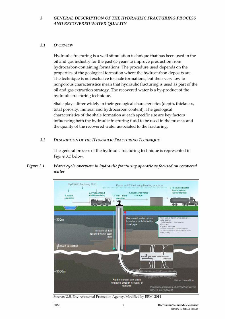
3.2 DESCRIPTION OF THE HYDRAULIC FRACTURING TECHNIQUE
The general process of the hydraulic fracturing technique is represented in Figure 3.1 below.
Figure 3.1 Water cycle overview in hydraulic fracturing operations focused on recovered water
Source: U.S. Environmental Protection Agency. Modified by ERM, 2014

ERM 10 RECOVERED WATER MANAGEMENT STUDY IN SHALE WELLS
In general terms, the technique consists of pumping a hydraulic fracturing fluid (a blend of water, proppant and additives) down the wellbore through an isolated steel pipe to reach the target formation. This pumping is done under high pressure to create a network of fractures in the hydrocarbon-bearing rock. The purpose of the proppant in the fracturing fluid is to hold the fractures open creating pathways that allow oil and gas to be produced from the reservoir formations and flow up the wellbore along with the injected fluids during flowback and during the subsequent well production phase.
The fracturing process happens at different stages along the leg of the well that is in contact with the shale formation (normally a horizontal leg). The process starts with the section of the well that is farthest from the vertical portion of the well. Each stage is kept under pressure for few hours, and at the end of each stage, a plug is set to isolate that fractured interval and allow the fracturing of the next stage. This process is repeated as many times as there are stages designed for each specific well. When the well is ready to be brought into production, the plugs are drilled out.1
Once the plugs are drilled out, the pressure is released and the direction of fluid flow reverses. The well is “cleaned up” by allowing water and excess proppant to flow up through the isolated steel pipe to the surface and the recovered water is captured and stored in closed steel tanks.
Operators strive to minimise proppant return, since the ultimate goal of a hydraulic stimulation is to convey and deposit the proppant within the fractures in the shale to maximise hydrocarbon flow.
The first water that returns to the surface is mainly known as flowback water and is basically the fracturing fluid that has been in contact with the shale formation. In some cases (depending on the retention characteristics of the formation, i.e., dry or wet formations), flowback water is mixed with formation water.
After the main volume of flowback has returned to the surface, often a low volume of produced formation water continues to exit the well. For the purpose of this study, any water that leaves the well after hydraulic fracturing is referred to as recovered water.
The recovered water is captured and stored in tanks on the surface before being sent to treatment and final disposal or reuse, which may take place onsite or offsite. In the case of offsite management, the recovered water is transported, typically by trucks, to an appropriate facility for proper management.
3.3 CHARACTERISTICS OF THE HYDRAULIC FRACTURING FLUID
The fracturing fluid is an engineered product and its final composition is defined only after the geological characteristics of the shale formation that will be stimulated have been analysed.
1 This technique is popularly referred to as “plug-and-perf” and is one of several multi-stage techniques used.

ERM 11 RECOVERED WATER MANAGEMENT STUDY IN SHALE WELLS
The most common base for the hydraulic fracturing fluid is water, mixed with proppant (typically sand), and a very limited proportion of additives. As reference values, it can be estimated that around 99.5% of the fluid is a mixture of water and sand, and the remaining 0.5% is additives.
The water can be obtained from various sources including surface water bodies, groundwater, the public water supply, industrial effluent or reused water from other fracturing activities. Nowadays, operators try to reduce the water volume that is used in the hydraulic fracturing fluid as much as possible, and they often reuse water in the process where it is practical. This results from an evolution of both the hydraulic fracturing technique itself and the additives, which have been improved by increasing their compatibility with different water qualities. In addition, operators have a strong interest in employing sustainable water practices.
Additives are used in hydraulic stimulation operations to elicit certain properties and characteristics that aid and enhance the operation. Therefore they are selected based on both the specific conditions of the shale formation and the desired characteristics of the hydraulic fracturing fluid. In this way, additives are used where needed with different purposes, including as a breaker, bactericide or biocide, clay stabilizer or control, corrosion inhibitor, crosslinker, friction reducer, gelling agent, iron control, scale inhibitor, and surfactant. Developments in this area have significantly reduced the quantity and toxicity of the additives required to hydraulically stimulate target reservoirs.
While the specific composition of the stimulation fluid varies according to the geological characteristics of the reservoir and the specific needs of the project, the range of additive types generally remains the same. There are different compositions available for each additive type, although only one composition is generally used in any given shale well. In addition, not all additive types may be used in every stimulation job, typically only 3-8 different additives compatible with the shale reservoir are used to obtain the characteristics necessary for stimulation.
3.4 RECOVERED WATER QUALITY
Recovered water consists of a mixture of the hydraulic fracturing fluid, including water, additives and proppant (typically sand), dissolved material from the shale formation that was in contact with the fluid, and formation water (also known as produced water), should it exist.
Recovered water parameters can vary widely between the different shale plays depending on the composition of the formation, but they can contain one or more of the following:
• Dissolved solids (chlorides, sulphates, and calcium), defined as total dissolved solids (TDS);
• Suspended solids – usually proppant and mineral scales (calcium carbonate and barium sulphate);
• Dispersed clay fines, colloids and silts;

ERM 12 RECOVERED WATER MANAGEMENT STUDY IN SHALE WELLS
• Traces of metals (calcium, magnesium, barium, strontium);
• Bacteria - acid producing bacteria and sulphate reducing bacteria,
• Iron solids (iron oxide and iron sulphide);
• Traces of oil and grease (more common if the shale formation produces primarily crude oil);
• Traces of naturally occurring radioactive material (NORM).
A summary of the different factors that influence recovered water quality is provided in Figure 3.2.
Figure 3.2 Recovered water quality
Source: Prepared by ERM, 2014
Most of the constituents of recovered water were originally part of the shale formation and the naturally occurring water that resides in it, which leaches/mixes with the flowback water while it resides in the formation during the hydraulic fracturing process. Produced formation water contains high levels of TDS on its own, and minerals leached out from the shale (e.g. barium, calcium, iron and magnesium) (Schramm, 2011); it may also contain dissolved hydrocarbons (e.g., methane, ethane, and propane) along with NORM (e.g., radium isotopes).
3.4.1 Factors influencing the volume of recovered water
One of the main factors influencing the volume of recovered water is the volume of hydraulic fracturing fluid that is used in the process, but the characteristics of the formation are also a key factor to be considered.
As previously mentioned, all shale plays are different and their geological characteristics are very site specific. For instance, each shale play has its own retention characteristics which play an important role in both the recovered water volume and quality.

ERM 13 RECOVERED WATER MANAGEMENT STUDY IN SHALE WELLS
Much of the water that is introduced as hydraulic fracturing fluid into a dry formation will be retained. This process is known as imbibition. Therefore the volume of water that returns to the surface as recovered water is significantly less than the volume injected as fracturing fluid. Furthermore, a dry formation does not contain much produced formation water, so the quality of the water recovered at the surface will primarily depend on the parameters of the hydraulic fracturing fluid, and the geological characteristics of the formation will have a limited influence. The opposite occurs with a wet formation, where existing produced formation water determines both the quality and volume of recovered water.
As a typical reference value, it may be expected that from 20 to 40% of the fluids pumped into the well for the hydraulic stimulation can be recovered when they flow back to surface. In some circumstances this may be as much as 100%). The additional fluids will remain trapped due to absorption and surface tension in the rock and clays of the shale formations.
3.4.2 Temporal variation in quality and volume of recovered water
Over an extended period of time, the volume of recovered water from a given well will decrease, but during the same time period, the concentration of many of the constituents will rise (Figure 4.3)
Recovered water starts out with a relatively low salinity (moderate TDS, similar to the injected water), and the salinity/TDS generally increases with time. There is a lack of published data on the chemical characteristics through time of recovered water from shale wells, and very little data showing concentrations (Hayes, 2009; Acharya et al., 2011). The limited information available does suggest that the water which does not initially return to the surface remains in contact with the new rock surfaces created as a result of the stimulation process and is able to dissolve certain constituents from the shale. The longer the water remains in the fractures or pore spaces, the higher the level of dissolved constituents is likely to be, until it reaches the saturation or equilibrium point. Produced waters which have been in contact with the shale reservoir for millions of years are much less variable in quality. This variation in both volume and quality of recovered water over time (the volume of water decreases whilst the constituent concentration increases) makes treating the recovered water more challenging through time.

ERM 14 RECOVERED WATER MANAGEMENT STUDY IN SHALE WELLS
Figure 3.3 Variability of TDS concentration through time in selected Marcellus shale wells
Source: Prepared by ERM, 2014 (with data from Hayes, 2009)
0
50
100
150
200
250
300
350
400
Day 0* Day 1 Day 5 Day 14 Day 90
TDS
/ Th
ousa
nds (
mg/
L)
C
H
I
J
O
P

ERM 15 RECOVERED WATER MANAGEMENT STUDY IN SHALE WELLS
4 IDENTIFICATION OF RECOVERED WATER MANAGEMENT OPTIONS
4.1 OVERVIEW
The variable volume and quality of recovered water during the fracturing process at a single site and across different shale plays, makes water management a key and challenging process in shale wells. The final decision on the recovered water management practice in shale wells is subject to a number of site specific conditions including, but not limited to, the characteristics of the formation, existing available management options, phase of the operations (e.g., exploration versus development), regulatory framework, and environmental and social conditions in the area.
This section presents a summary of current water management practices that are used globally in shale wells and provide a general overview of the framework and factors existing behind the decision making process for selecting the most appropriate recovered water management practice for a specific site.
4.2 IDENTIFICATION OF CURRENT MANAGEMENT PRACTICES PERFORMED GLOBALLY
In order to identify the current management practices that are globally applied to shale wells, ERM has conducted a desktop review of publicly available information followed by a validation process through interviews with various operators.
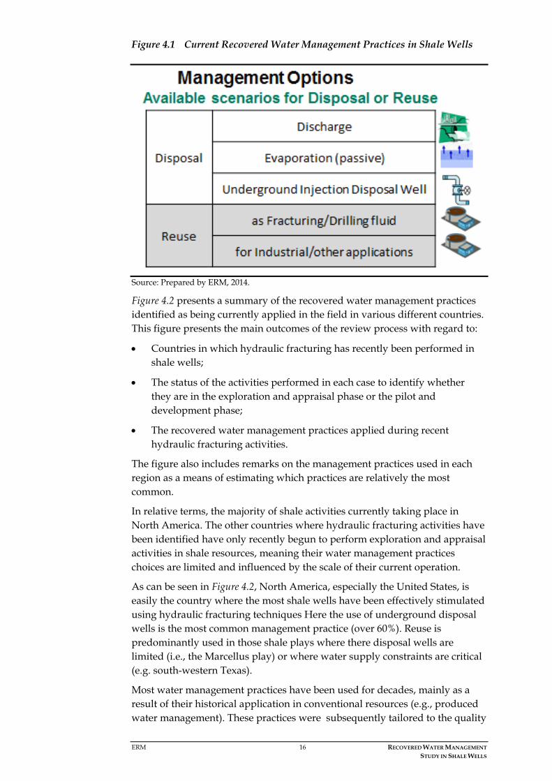
As a result of these reviews, two broad management practice categories have been identified for effectively handling recovered water once it reaches the surface: disposal and reuse. The basic difference between them is the final end use of the recovered water. For each of these two broad management practices, particular scenarios have been identified, as represented in Figure 4.1. Based on the management option and scenario selected, a fit-for-purpose treatment train must be designed to achieve the target parameters required for the water before its final disposal or reuse.
ERM 16 RECOVERED WATER MANAGEMENT STUDY IN SHALE WELLS
Figure 4.1 Current Recovered Water Management Practices in Shale Wells
Source: Prepared by ERM, 2014.
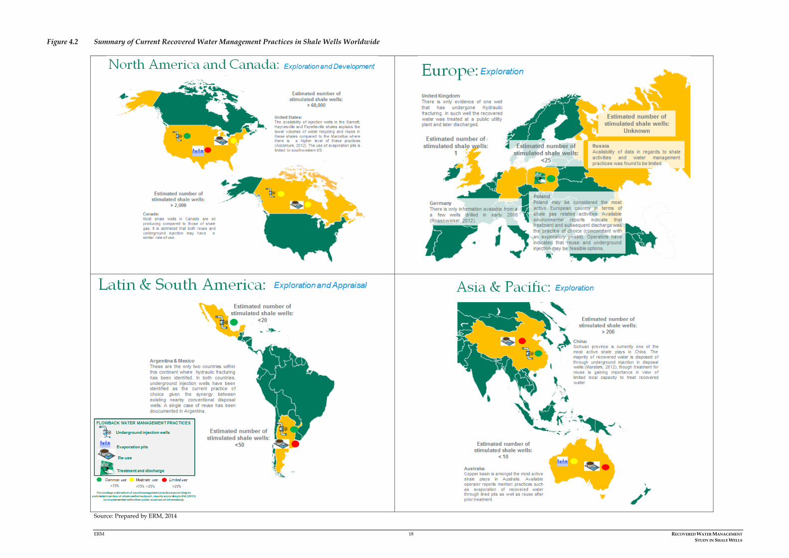
Figure 4.2 presents a summary of the recovered water management practices identified as being currently applied in the field in various different countries. This figure presents the main outcomes of the review process with regard to:
• Countries in which hydraulic fracturing has recently been performed in shale wells;
• The status of the activities performed in each case to identify whether they are in the exploration and appraisal phase or the pilot and development phase;
• The recovered water management practices applied during recent hydraulic fracturing activities.
The figure also includes remarks on the management practices used in each region as a means of estimating which practices are relatively the most common.
In relative terms, the majority of shale activities currently taking place in North America. The other countries where hydraulic fracturing activities have been identified have only recently begun to perform exploration and appraisal activities in shale resources, meaning their water management practices choices are limited and influenced by the scale of their current operation.
As can be seen in Figure 4.2, North America, especially the United States, is easily the country where the most shale wells have been effectively stimulated using hydraulic fracturing techniques Here the use of underground disposal wells is the most common management practice (over 60%). Reuse is predominantly used in those shale plays where there disposal wells are limited (i.e., the Marcellus play) or where water supply constraints are critical (e.g. south-western Texas).
Most water management practices have been used for decades, mainly as a result of their historical application in conventional resources (e.g., produced water management). These practices were subsequently tailored to the quality

ERM 17 RECOVERED WATER MANAGEMENT STUDY IN SHALE WELLS
and volume of recovered water in shale operations. As a result, the considerable current experience (and ongoing research) in both shale and conventional resources has resulted in water management activities being conducted to high environmental and social standards, whilst still remaining economically viable.
It is not the purpose of this study to provide exhaustive country-by-country information on the management practices used, rather to give a general overview of the current status of these management options across the globe.
ERM 18 RECOVERED WATER MANAGEMENT STUDY IN SHALE WELLS
Figure 4.2 Summary of Current Recovered Water Management Practices in Shale Wells Worldwide
Source: Prepared by ERM, 2014

ERM 19 RECOVERED WATER MANAGEMENT STUDY IN SHALE WELLS
4.3 DECISION MAKING PROCESS
The choice of a water management practice is usually decided before stimulation but, as mentioned above, it is subject to a number of factors. The most important factor is how clean the water should be to enable the intended end use.
Exploratory drilling delivers key information on the shale geology, meaning the relative volumes of fracturing fluids may be calculated, as well as the expected volume of recovered water that is to be managed. Nonetheless, selecting a practice can be quite challenging as many of the influencing factors may vary within the same shale play; this is why each well must have a tailor-made water management strategy.
Figure 4.3 Decision Making Process for Recovered Water Management in Shale Wells
Source: Prepared by ERM, 2014
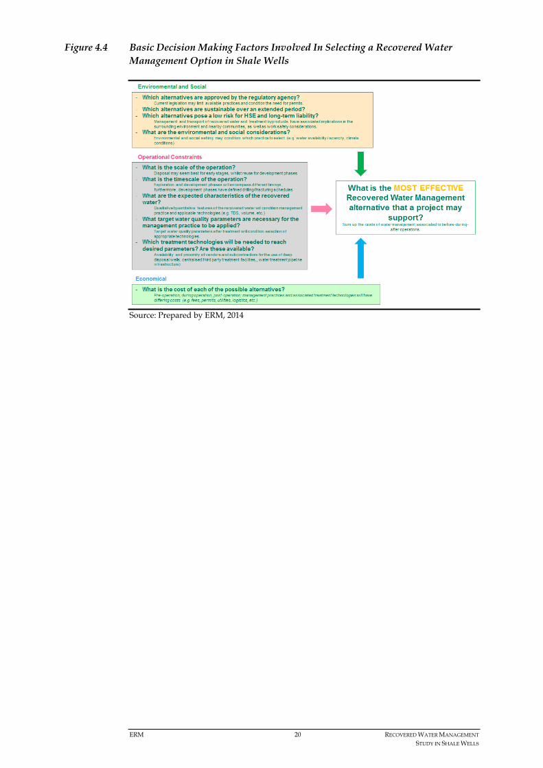
A summary of some of the main decision making factors involved is presented in Figure 4.4.
ERM 20 RECOVERED WATER MANAGEMENT STUDY IN SHALE WELLS
Figure 4.4 Basic Decision Making Factors Involved In Selecting a Recovered Water Management Option in Shale Wells
Source: Prepared by ERM, 2014

ERM 21 RECOVERED WATER MANAGEMENT STUDY IN SHALE WELLS
5 DESCRIPTION OF DISPOSAL / END USE OPTIONS AND TREATMENT TECHNOLOGIES FOR RECOVERED WATER
5.1 OVERVIEW
This section presents a more detailed description of each of the existing recovered water management practices mentioned in the previous sections. The description includes details on technical functioning and energy use, technical and practical limitations, and advantages, as well as the identification and management of any by-products created during the treatment and management of recovered water.
This section also provides a general overview of viable technologies that are applied in the field for treating recovered water associated to shale wells. For reference purposes, information on the most common treatment technologies associated to each management practice has been provided.
As many factors influence the decision of which water management practices are used, there is intrinsic variation. Two situations where the same management practice is applied may vary in terms of actual costs (e.g., using an existing facility versus constructing a new one), energy requirements, limitations, and so on, determined by the factors outlined in Figure 4.4.
5.2 RECOVERED WATER MANAGEMENT PRACTICES AND TREATMENT TECHNOLOGIES
As mentioned in previous sections, two broad management practice categories for effectively handling recovered water once it reaches the surface have been identified: disposal and reuse. Within each of these practices, different scenarios have been identified including discharge to surface water, underground injection into disposal wells, passive evaporation ponds, and reuse in fracturing/drilling fluids or other industries.
According to the end use of the recovered water, applicable regulatory/industry considerations will condition both its suitability and the treatment technologies required for selected management practice.
The process by which recovered water attains these parameters is commonly known as a treatment train, and this can range from simple treatments, such as the basic settling of suspended solids, to highly specialised processes that are able to produce clean fresh water.
Figure 5.1 presents a summary of the most common treatment technologies used for recovered water. They have been grouped by main target parameters.

ERM 22 RECOVERED WATER MANAGEMENT STUDY IN SHALE WELLS
Figure 5.1 Main Treatment Technologies Available for Recovered Water in Shale Wells
Source: Prepared by ERM, 2014
Section 5.6 further details the listed treatment technologies along with their main features, categorised by the main target constituents that are found in recovered water.
For each of the identified scenarios, there will usually be a basic treatment train related to the constituents that are to be dealt with. Even though several treatment technologies have been described, not all of them are commonly used.
The following sections provide a description of each management practice and the basic treatment trains associated to each management practice scenario. Where more than one treatment technology for any given constituent is available, the most commonly used technology associated to that specific scenario is marked in bold and underlined. Furthermore, specific by-products from the treatment are also identified.
5.3 DESCRIPTION OF DISPOSAL OPTIONS
There are a limited number of disposal options for water recovered from shale wells. Disposal options are effective when applied in the early phases of the project (during the exploration and appraisal phase) where the volumes of recovered water are relatively low or moderate when compared to other advanced phases of the project (e.g., full development phase) and where reuse is not a feasible option.
5.3.1 Disposal: Discharge to Surface Water
Discharge to surface water typically refers to treated recovered water being released into a surface water body that is normally also used as a source for domestic or industrial purposes. This input may also influence the current environmental conditions of the water body (e.g., it could support minimum

ERM 23 RECOVERED WATER MANAGEMENT STUDY IN SHALE WELLS
river flows or wetlands), especially in areas where water may be scarce. Discharge is not a common management option for recovered water in shale wells, and it is not allowed in the US. In areas where discharge is allowed and is chosen by the operator, an extensive treatment process is necessary to remove any oil and grease, TSS, metals, and TDS to achieve water quality that complies with the applicable standards. One of the major limitations in the application of this management practice in shale wells is the high salinity of the recovered water. The cost of treating the recovered water (pre-treatment and desalination) in treatment plants to achieve the desired water quality involves a high energy demand, meaning this practice less sustainable when the whole process is reviewed. If discharge was permitted to a saline water body, like a sea or a saline aquifer, the requirement for reaching an acceptable level TDS may be less than for a fresh water body. The other requirements would not change. The discharge of recovered water into a saline water body is not currently practiced.
So far, discharge to surface water has only been the method of choice in a small number of sites, and where it has been applied, it has mainly been for early stimulations in the exploration and appraisal phases (e.g., in the UK, Poland, and Australia). This is mostly because of the combined conditions of restrictions in use or non-availability of underground disposal wells and no practical subsequent reuse of the recovered water. It can be concluded that this is by far the least practical and sustainable option for managing recovered water. Treatment train for disposal: discharge to surface water
In order to use discharge as a disposal option for highly saline water (as is the case of the recovered water), treatment plants must remove the salt from the water. Before the water is desalinated, it must be pre-treated to remove solids, oil and grease, and often metals.
Figure 5.2 shows the common/potential treatment train for discharging treated recovered water to a surface water body. The final design of the treatment train is subject to both the quality of the recovered water (site specific) and the standard limits for discharge into surface water bodies defined in each country.

ERM 24 RECOVERED WATER MANAGEMENT STUDY IN SHALE WELLS
Figure 5.2 Common potential treatment train for Disposal: Discharge Scenario
Source: Prepared by ERM, 2014 Technical Description of Disposal: Discharge to Surface Water
A comprehensive description of this management scenario and its technical diagram is presented in Factsheet 1 below.

25
Practice Description :
Recovered water is discharged to a surface water body, usually after being sent to a certified wastewater treatment facility to attain water quality parameters within applicable discharge limits.
Energy Use:
Moderate to high, depending on technologies used to condition wa-ter properties to applicable discharge limits.
Targeted Water Quality Parameters:
Will ultimately depend on existing regulations for discharge, which may require high standards in terms of TDS/chemical concentrations. May require anything from basic settling/filtration to more advanced desalination treatments.
Treatment by-product(s):
Will depend on treatment train; typically a combination of sludge, other solids, and concentrated brine; all these may be of variable toxicity, with considerable concentrations of metals and radionucli-des.
Management Practices for Recovered Water Treatment
Fact Sheet 1
DISPOSAL –Discharge
General Notes
Outside the U.S. discharge is usually the preferred option during
exploration phases, provided there are no subsequent fracturing
activities and/or absence of other management options.
Disadvantages:
- May require treatment to a relatively high standard with associa-
ted high costs (e.g. high TDS water)
- It is possible that existing treatment facilities may struggle to
handle certain volumes/qualities of recovered water.
Advantages:
- Minimal permitting costs when dealing with low volumes of reco-
vered water
- Use of existing facilities
- Although not common practice, discharging to the sea would
require less intensive TDS (salinity) treatment , and hence would
probably be of lower cost.
Main Associated Impacts
(S/H: Social /Health; E: Environmental)
Type Description Value
S/H Limited pollution risk to domestic/
industrial surfacewater users Low
E Water is discharged according to
applicable legislation Low
Cost
Phase Description Value
Prior to
Operation: Related to obtaining permits. Low
During
Operation:
Will depend mostly on fees related
to applied treatment technologies
which can be costly (depending on
quality needs of environment for
discharge).
Moderate - High
After
Operation: Negligible costs Low
Main Considerations for Selection
Distance/volume of water transport to a treatment facility.
It is probable that water may need desalination before dischar-ge with associated high running costs given expensive techno-logy needed to treat this parameter.
Water transport truck. Source: courtesy of OGP members, 2014
Outfall pipe. Source: courtesy of OGP members, 2014

ERM 26 RECOVERED WATER MANAGEMENT STUDY IN SHALE WELLS
Technical Diagram of Disposal: Discharge to Surface Water
Source: Prepared by ERM, 2014

ERM 27 RECOVERED WATER MANAGEMENT STUDY IN SHALE WELLS
5.3.2 Disposal: Passive Evaporation
Evaporation is used in some arid locations as a disposal practice for recovered water from shale wells. It consists of isolated, lined, shallow ponds where water is stored and evaporated from using the natural energy of the sun and the wind.
This practice has been identified mainly in the western United States and Australia. Typically it is used in remote areas and places that have significant open spaces where shallow evaporation ponds can be located. There are several third-party commercial waste disposal companies in the United States that use evaporation as their primary method of managing water. Unless the air is dry and there are local winds, evaporation does not occur quickly enough to be an economical practice. Treatment train for disposal: passive evaporation
Evaporation does not require pre-treatment to remove contaminants. Nevertheless, if the recovered water contains any free oil, it should be removed before the water is sent to the pond. Any oil floating on a pond surface will necessitate the entire pond being covered with netting to protect migratory birds.
Figure 5.3 shows the common/potential treatment train for the passive evaporation of recovered water.
Figure 5.3 Common potential treatment train for Disposal: Passive Evaporation Scenario
Source: Prepared by ERM, 2014 Technical description of disposal: Passive evaporation
A comprehensive description of this management scenario and its technical diagram is presented in Factsheet 2.

28
Prac ce Descrip on :
Passive evapora on from permi ed lined evapora on ponds. These are rela vely shallow and recovered water will typically need oil/grease pre‐treatment (requiring use of addi onal lined slud‐ge/se lement ponds).
Energy Use:
Low, associated to pre‐treatment; low energy requirements for basic oil/water separa on (acceptance pits, gun barrel tanks or other).
Targeted Water Quality Parameters:
Low hydrocarbon content of flowback water (non‐sheen producing) for be er evapora on results.
Treatment by‐product(s):
Oil/grease sludge from pre‐treatment (sludge/se lement ponds) and sediments (the la er associated to pond liner disposal and pond closure).
Management Prac ces for Recovered Water Treatment
Fact Sheet 2
DISPOSAL – Evapora on
General Notes
This op on is used primarily in a few western U.S. states and Austra‐
lia with large open land areas and dry climates, but it represents only
a small percentage of the total water management prac ces cu‐
rrently in use worldwide.
Disadvantages:
‐ Not prac cable in humid climates;
‐ May create air quality and salt deposi on problems (excessive
buildup of sediments);
‐ NORM control.
Advantages:
‐ Rela vely low cost in comparison to other prac ces;
‐ In arid climates, takes advantage of natural condi ons of humi‐
dity, sun, and wind;
‐ Typically located in remote areas.
Main Associated Impacts
(S/H: Social /Health; E: Environmental)
Type Descrip on Value
S/H Vola le organic compounds (VOCs) may
cause air pollu on issues in the inme‐
diate surroundings.
Moderate
E Covering of water/sludge pits will pre‐
vent avifaunal contact. Low
Phase Descrip on Value
Prior to
Opera on:
Related to pit permi ng and
construc on. Moderate
During
Opera on:
Related to opera onal features of
selected pre‐treatment for oil/
water separa on .
Low
Cost
A er
Opera on:
Related to pit closure and restora‐
on Low
Main Considera ons for Selec on
Geographical loca on of the pits, being only prac cable in areas with an arid climate. Evaporation pond in Australia. Source: courtesy of OGP members

ERM 29 RECOVERED WATER MANAGEMENT STUDY IN SHALE WELLS
Technical Diagram of Disposal by Passive Evaporation
Source: Prepared by ERM, 2014

ERM 30 RECOVERED WATER MANAGEMENT STUDY IN SHALE WELLS
5.3.3 Disposal: Underground Injection Disposal Wells
Underground injection into disposal wells is the most commonly used practice for disposing of recovered water from shale wells. This practice is actually very common for disposing of water not only from shale wells but also other common types of hydrocarbon formations. Clark and Veil (2009) showed that 98% of the produced water from all types of onshore wells in the U.S. is managed through this practice. In the specific case of recovered water from shale wells in the U.S., nearly all of it is sent to disposal wells.
Underground injection consists of sending recovered water into isolated formations. This may be done by either using old wells that are technically modified to become disposal wells, or the third party commercial wells that are drilled specifically for this purpose. Not all wells can be used as disposal wells. The well site must be studied in order to guarantee the technical feasibility of converting it into a disposal well. Disposal wells are monitored and controlled and have to comply with the existing regulatory framework applicable to them. Treatment train for disposal: underground injection disposal wells
When water is injected into a disposal well only minimal pre-treatment is needed, in order to prevent the formation from plugging.
Figure 5.4 shows the common/potential treatment train for underground injection of recovered water into disposal wells.
Figure 5.4 Common potential treatment train for Disposal: Underground Injection Disposal Well Scenario
Source: Prepared by ERM, 2014
The pre-treatment will typically involve passing the recovered water through an oil/water separator so free oil can rise to the top and be skimmed off. This way, solids can fall to the bottom and can be captured and removed later as sludge. Very few if any chemical additives are used but this depends on the quality of the recovered water and the characteristics of the disposal well.
Considering that the existing regulations relating to the management of disposal wells vary widely between countries, additional treatments may be required, for instance to remove metals or microbes, as happens in Argentina.

ERM 31 RECOVERED WATER MANAGEMENT STUDY IN SHALE WELLS
Technical description of disposal: underground injection in disposal wells
A comprehensive description of this management scenario and its technical diagram is presented in Factsheet 3.

32
Prac ce Descrip on :
This management prac ce involves injec ng liquids into an isolated reservoir through the use of a permi ed well that is specifically de-signed for the disposal of produced & flowback water associated to conven onal and shale explora on.
Energy Use:
Low‐Moderate, associated with pre-treatment energy requirements and high volume pumps for injec on.
Targeted Water Quality Parameters:
Basically pre-treatment for TSS (e.g. by gravity se ling or filtra on), oil/grease (e.g. separators) and in some cases microbes (e.g. bioci-des) is needed prior to disposal, but may require further treatment depending on disposal well management prac ces.
Treatment by‐product(s):
Only by-products of pre-treatment, where necessary, usually sludge which is normally managed as industrial waste and may contain me-tals and NORM.
Management Prac ces for Recovered Water Treatment
Fact Sheet 3
DISPOSAL -Injec on in Disposal Well
General Notes
In the US, EPA and state agencies recognise this as a safe, widely
used, proven, and effec ve method for disposing of wastewater.
Disposal wells can be permi ed either by operators for their own
use or by third-party commercial waste management companies.
Disadvantages:
- Pre-treatment o en required to prevent forma on plugging;
- Trucking will be o en required to reach disposal site;
- Forma on permeability, storage capacity and pressure can be
limi ng factors for disposal well loca ons;
- Few cases of low magnitude seismic events have been linked to
improperly sited/managed disposal wells
Advantages:
- This type of well is commonly available in conven onal oil and gas producing plays;
- Abandoned O&G wells can be converted to disposal wells (subject to prior technical studies and modifica ons);
- Can handle large volumes of waste;
- Tend to have rela vely low cost (if using exis ng wells or suppor-ng a large number of shale ac vi es (e.g. s mulated wells)
Main Associated Impacts
(S/H: Social /Health; E: Environmental)
Type Descrip on Value
S/H Social/health impacts are very low, or
even negligible for a properly mana-
ged disposal well
Low
E Injec on of recovered water in isola-
ted forma ons limits any environmen-
tal incidence
Low
Phase Descrip on Value
Prior to
Opera on:
Related to obtaining injec on per-
mits ; or conversion of old well if non
existent
Low* (if using
an exis ng
well)
During
Opera on:
Related to pre-treatment, and addi-
onal costs of commercial disposal. Low
Cost
A er
Opera on:
Related to plugging and abandon-
ment of the well. Low
Main Considera ons for Selec on
Regulatory framework may limit the applicability of this
prac ce;
Availability of geological features that support injec on will limit loca ons where this type of well may be drilled
Target water quality parameters before disposal are dicta-ted by regulators
Injec on well at Commercial Disposal Falicity in Texas.
Source: courtesy of OGP members, 2014

ERM 33 RECOVERED WATER MANAGEMENT STUDY IN SHALE WELLS
Technical Diagram of Disposal: Underground Injection in Disposal Wells
Source: Prepared by ERM, 2014

ERM 34 RECOVERED WATER MANAGEMENT STUDY IN SHALE WELLS
5.4 DESCRIPTION OF REUSE SCENARIOS
There are many factors that may favour water reuse practices as opposed to disposal. The volumes of water needed to perform a well stimulation may be a critical constraint in areas where this resource is scarce, or disposal practices, which are generally reckoned to be very cost effective, may not be so in a particular situation. Important features of the recovered water itself that influence this decision include:
1) The volume of recovered water: wells that produce significant and continuous volumes of recovered water are preferred for reuse due to the logistics involved in storing and transporting the water.
2) The quality of recovered water: salt content, total suspended solids and hardness of the recovered water may affect possible reuse. Nevertheless, recent technological developments have increased the possibilities for reusing recovered water in fracturing and drilling processes.
Depending on the quality, a reuse scenario may be an effective recovered water management strategy, but there are a number of limitations that may not be fully applicable to shale wells. Reuse is considered a sustainable and practical option for pilot or development phases, and of more limited application in exploration and appraisal phases.
The main reuse scenarios associated to recovered water are described in terms of the level/intensity of treatment (e.g., from basic filtration, through chemical processes, up to intensive desalination technologies) required to achieve particular end-uses, either within shale operations or other industrial processes.
5.4.1 Reuse in Fracturing or Drilling Fluids
Following a basic or intermediate treatment, recovered water from shale wells can be reused either in fracturing fluids or even as drilling fluid for other shale wells. This is a very cost-effective practice as it reduces an operator’s expenses in both water sourcing and recovered water management.
The main limitation in the application of this management practice is that it requires other wells to be ready for hydraulic fracturing or drilling at the time when the recovered water is produced in another location. In addition, the feasibility of this practice also relies on the distance between the locations where recovered water is produced and reused, as well as the question of whether there is sufficient recovered water for subsequent operations. Treatment train for reuse: fracturing or drilling fluid
The treatment train for this scenario depends on the quality of the recovered water that is collected and on the quality of water required where it will be reused. Therefore, two general treatment trains have been defined: basic treatment and intermediate treatment.

ERM 35 RECOVERED WATER MANAGEMENT STUDY IN SHALE WELLS
In basic treatment, the recovered water is passed through simple filtration devices (often bag/sock/cartridge filters and oil/water separators) to remove large solid particles and oil/grease. The filtered water is blended with other water sources to make up the drilling or fracturing fluid for future wells in the same field. This simple process is performed onsite with water easily transferred to nearby wells for reuse. This basic treatment does not remove oil, metals, or compounds other than large solid particles.
The intermediate treatment is more comprehensive than the basic level. The endpoint in this case is clean brine. This means that the treatment is designed to remove finely dispersed oil, metals, and scale-causing compounds, but no TDS are removed.
Figure 5.5 shows the common/potential treatment train for the basic and intermediate treatment of recovered water for reuse as fracturing/drilling fluid.
Figure 5.5 Common potential treatment train for Reuse in fracturing and drilling fluid: (Basic and intermediate treatment)
Source: prepared by ERM, 2014 Technical description reuse: basic and intermediate water treatment
A comprehensive description of this management scenario and its technical diagram is presented in Factsheet 4.

36
Prac ce Descrip on :
Storage of recovered water in a permi ed lined reservoir or sealed tanks and reuse for the subsequent s mula on/drilling of another well a er BASIC (e.g. filtra on, separa on) and/or INTERMEDIATE (e.g. clarifica on, oxida on) treatment steps.
Energy Use:
Low‐Moderate: Basic treatment is usually not energy intensive, but intermediate level may be energy intensive
Targeted Water Quality Parameters:
Brine water can be as effec ve as freshwater. Parameters such as: pH, iron, bicarbonate, calcium, magnesium, boron, sulphate, TDS, sodium, chloride, potassium and bacteria can limit reuse.
By‐product(s) of treatment:
Accumulated solids; sludge with high concentra ons of metals and NORM
Management Prac ces for Recovered Water Treatment‐
Fact Sheet 4
REUSE – Fracturing/Drilling fluid (Basic & Intermediate)
General Notes
In a development scenario, recovered water can be stored in centra‐
lised pits for reuse ‐‐ o en mixed with fresh water to achieve desired
quali es for reuse. Centralised loca ons imply larger pits, which may
have addi onal permi ng requirements.
Disadvantages:
‐ Requires storage facili es;
‐ Lined pits or tanks may be required;
‐ Water can only be recycled a finite number of mes before quali‐
ty forces disposal or further ADVANCED treatment;
‐ Must have a new well wai ng to be s mulated so long‐term wa‐
ter storage is avoided.
Advantages:
‐ Minimises costs of operators having to source water and later
treatment of recovered water;
‐ Sustainable approach that conserves water resource;
Main Associated Impacts
(S/H: Social /Health; E: Environmental)
Type Descrip on Value
S/H Poten al for exposure to VOCs if
pits are used, will be significantly
lower using tanks
Low
E Reuse scenarios minimise impact,
by products from pre‐treatment are
manageable
Low
Phase Descrip on Value
Prior to
Opera on:
Related to permi ng and reservoir
construc on; or Low in case of tanks. Low‐Moderate
During
Opera on:
Assumes no trucking and/or
minimum pre‐treatment. Low
Cost
A er
Opera on:
Related to size of pit and closure
requirements; or Low in case of
tanks.
Low ‐ Moderate
Main Considera ons for Selec on
Dilu on (prac ce also called "Blending"), can be a prac cal and cost effec ve method of treatment before reuse;
Volume of water recovered should be large enough to limit water intake from other sources;
Other drilling/fracturing ac vi es must be performed in the vicinity to take full advantage of this management op on;
Higher levels of parameters such as TDS and metals a er every subsequent fracturing will warrant further treatment to make reuse compa ble
Discharge of recovered water to a centralised pit for reuse
Source: courtesy of OGP members, 2014
Recovered water may undergo se ling in sealed tanks for
later reuse. Source: courtesy of OGP members, 2014

ERM 37 RECOVERED WATER MANAGEMENT STUDY IN SHALE WELLS
Technical Diagram Reuse: Basic and intermediate water treatment
Source: Prepared by ERM, 2014

ERM 38 RECOVERED WATER MANAGEMENT STUDY IN SHALE WELLS
5.4.2 Reuse in other industrial activities
In order to reuse water in other industrial activities advanced treatment is required and the endpoint is clean fresh water with low TDS. Currently, not very much recovered water is treated to this level and reused in oil and gas operations or in other industries. It is applied in locations with no other lower-cost water treatment options asw well as in areas with water shortages.
In very dry locations, with long-term water shortages like west Texas, some operators use advanced treatment processes in order to generate their own dedicated water supply. Recovered water that undergoes successive basic/intermediate treatment steps gradually increases in TDS to the point where it can no longer be used in the shale operation. For this reason, if water is going to be continuously reused, it is necessary to desalinate it Treatment train for reuse: other industrial activities
For advanced treatment, the basic and intermediate procedures explained above are applied followed by desalination technologies, such as thermal distillation, which are expensive. It is important to note that most recovered water has TDS higher than 40,000 mg/L (Veil, 2012), and therefore reverse osmosis is not a practical option.
Figure 5.6 shows the common/potential treatment train for the advanced treatment of recovered water for reuse in other industrial activities.
Figure 5.6 Common potential treatment train for Reuse in other industrial activities
Source: Prepared by ERM, 2014 Technical description for reuse: other industrial sectors
A comprehensive description of this management scenario is presented in Factsheet 5.
39
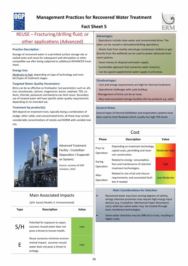
Prac ce Descrip on :
Storage of recovered water in a permi ed surface storage site or sealed tanks and reuse for subsequent well s mula on or other compa ble use a er being subjected to addi onal ADVANCED treat-ment.
Energy Use:
Moderate to high, depending on type of technology and num-ber/types of treatment stages.
Targeted Water Quality Parameters:
Brine can be as effec ve as freshwater, but parameters such as: pH, iron, bicarbonate, calcium, magnesium, boron, sulphate, TDS, so-dium, chloride, potassium and bacteria can limit reuse. Secondary use of treated water will have specific water quality requirements depending on its intended use.
Treatment by‐product(s):
Will depend on treatment train, typically being a combina on of
sludge, other solids, and concentrated brine; all these may contain
considerable concentra ons of metals and NORM with variable toxi-
city.
REUSE – Fracturing/drilling fluid; or
other applica ons (Advanced)
General Notes
Several types of thermal dis lla on and evapora on systems have
been used to treat flowback which usually has high TDS levels.
Disadvantages:
- Cost and energy requirements are high for thermal treatment;
- Opera onal challenges with scale buildup;
- Management of brine can be an issue.
- May need associated storage facili es (for by-products e.g. salts)
Advantages:
- Byproducts include clean water and concentrated brine. The
la er can be reused in s mula on/drilling opera ons;
- Waste heat from nearby natural gas compressor sta ons or gas
directly from the wellhead can be used to power advanced treat-
ment systems.
- Saves money on disposal and water supply;
- Sustainable approach that conserves water resource;
- Can be a good supplemental water supply in arid areas.
Main Associated Impacts
(S/H: Social /Health; E: Environmental)
Type Descrip on Value
S/H Poten al for exposure to vapor;
assumes reused water does not
pose a threat to human health.
Low
E Reuse scenarios minimise environ-
mental impact; assumes reused
water does not pose a threat to
ecology.
Low
Phase Descrip on Value
Prior to
Opera on:
Depending on treatment technology
capital costs, permi ng and reser-
voir construc on.
Moderate-High
During
Opera on:
Related to energy consump on,
fees and maintenance of selected
treatment technologies.
High
Cost
A er
Opera on:
Related to size of pit and closure
requirements; and associated facili-
es if needed
Low-Moderate
Main Considera ons for Selec on
Recovered water may have varying degrees of salinity, energy intensive processes may require high energy input devices (e.g. Crystalliser, Mechanical Vapor Recompres-sion); while less saline water may be treated through basic membrane technologies.
Some water chemistry may be difficult to treat, resul ng in higher costs.
Advanced Treatment
Facility : Crystallizer
(Separa on / Evapora -
on System)
Source: courtesy of OGP
members, 2014.
Management Prac ces for Recovered Water Treatment
Fact Sheet 5

ERM 40 RECOVERED WATER MANAGEMENT STUDY IN SHALE WELLS
Technical Description for Reuse in other Industrial Sectors
Source: Prepared by ERM, 2014

ERM 41 RECOVERED WATER MANAGEMENT STUDY IN SHALE WELLS
5.5 SUMMARY OF THE MAIN MANAGEMENT OPTIONS
Table 5.1 presents a summary of the identified water management practices, along with a brief explanation of their main attributes, for comparative purposes.
Based on a qualitative assessment of aspects such as energy use, financial cost, and environmental and social impacts, it can be concluded that both reuse of recovered water, either in fracturing or drilling fluids (i.e., only basic-intermediate treatment required), and underground injection into disposal wells constitute effective recovered water management scenarios from an economic/environmental perspective.
On the other hand, practices that may be considered less financially viable or environmentally effective, according to the criteria used, are discharge into surface water bodies and reuse in other industrial activities, given the advanced treatment technologies required, especially for TDS removal. Although the described impacts may be very similar and relatively low (green in Table 5.1) due to the industry’s ability to mitigate them, the energy/cost factors can vary greatly. However, in practice, when a management practice is being selected, the other factors mentioned in previous sections are also considered. These include the different operational conditions of the exploration versus development phase, and social setting.

ERM 42 RECOVERED WATER MANAGEMENT STUDY IN SHALE WELLS
Table 5.1 Summary of Key Aspects of Identified Management practices
*: Transport issues have not been considered since these may apply to varying degrees to all management practices Source: Prepared by ERM, 2014.
Factsheet Management Category Type Description Energy Use Cost* Main Associated
Social/Health ImpactsMain Associated
Environmental Impacts
1 Disposal DischargeRecovered water is discharged to a surface water body, usually after
being sent to a certified wastewater treatment facility to attain parameters within acceptable discharge limits.
High standard discharge parameters may necessitate intensive treatment
Will depend mostly on fees related to applied treatment technologies which can be expensive, unless
discharged to sea which would limit level of TDS removal
Limited pollution risk to domestic/industrial surfacewater
users
Impact is low since water is treated to applicable standards
2 Disposal EvaporationPassive evaporation from permitted lined evaporation ponds
constructed specifically for this use. These are only valid in arid climates
Limited pre-treatment energy requirements will have a relatively
low power consumption
Ponds require a large surface area to handle large volumes of recovered
water
Volatile organic compounds (VOCs) may cause localised air pollution
issues
Impact is low as water/sludge pits are covered with nets to prevent contact
with avifauna
3 Disposal Underground injection well
Injection into permitted disposal wells. This is a popular option where it is permitted, especially during development phases, but specific geological requirements limit locations where these wells can be
drilled.
Related to pre-treatment energy requirements and use of high volume pumps for injection
Relatively low pre-treatment costs and fees
Limited risk of groundwater pollution from wells that are managed
correctly
Impact is low due to injection in deep isolated formations
4 Reuse as fracturing/drilling
fluid
Recovered water trated to basic/intermediate level is stored in permitted reservoirs/tanks and reused in subsequent
stimulation/drilling. Brine can reused for succesive fracturing, but will have limited reuse cycles until further treatment is applied
Basic treatment is usually not energy intensive, but intermediate
level may be so
Site pre-treatment and use of ponds/tanks that need associated
permits and construction
Potential exposure to vapours if pits are used, negligible exposure with
tanks
Reuse scenarios minimise environmental risks/impacts, limited number/volume of by products from
pre-treatment
5 Reuseas fracturing/drilling fluid; other industrial
uses
Recovered water treated to advanced level is stored in permitted reservoirs/tanks and reused in subsequent stimulation/drilling or other compatible use. Creates a pure water stream that can have a wider
variety of uses, as well as significant dry deposits.
Desalination technologies are generally energy intensive
Usually requires a comprehensive treatment train (basic, intermediate and advanced) with associated fees
for treatment
Potential exposure to vapours if pits are used, negligible with tanks;
reused water does not pose a threat to human health
Reuse scenarios minimise environmental risks/impacts; reused
water does not pose a threat to ecology

ERM 43 RECOVERED WATER MANAGEMENT STUDY IN SHALE WELLS
5.6 DESCRIPTION OF TREATMENT TECHNOLOGIES
The preceding sections have described the different management practices that have been identified and their associated treatment trains. This section further describes each of the treatment technologies involved including:
• A basic description of how the technology works (including a photo of typical equipment used);
• The main target constituents to be treated (note that certain technologies may be able to further treat other constituents);
• The relative costs and energy use;
• Advantages and disadvantages of the technology; and
• Treatment by-products.
For completeness, microbe removal technologies have been included, although these are not considered to be treatment for recovered water, as they are usually used in the development of new fracturing fluid.

ERM 44 RECOVERED WATER MANAGEMENT STUDY IN SHALE WELLS
5.6.1 Treatment technologies focused on Total Suspended Solids and Heavy Metal removal
Mechanism/Process: Filtration
Description: Removal of large solids like sand and mineral scales through simple media filters or bag/sock filters.
Granular Activated Carbon media filter
Source: OGP, 2014 Target parameters: -Total Suspended Solids (TSS)
Cost/Energy use: Running costs and energy use are relatively low.
Advantages: -Low cost, low energy use -Effective TSS removal for pre-treatment
Disadvantages: -Grain size and distribution affects hydraulic performance of filtration process and efficiency of particle removal; - Time: slow head-loss accumulation plus high capacity for accumulating solids will produce long filter runs -Filter maintenance
By-product of treatment: -Used bag/sock filters -Used media -Backwash of media filters
Mechanism/Process: pH adjustment, coagulation/flocculation, sedimentation, and clarification Description: Designed to remove metals from flowback and produced water; lime or another chemical is added to raise the pH. This supports formation of metal sludges (metal hydroxides when lime is used). Coagulants are added to promote flocculation/settling, and then the wastewater is sent to a clarifier. The sludge is often dewatered in a filter press.
pH adjustment equipment Source: OGP, 2014
Target parameters: -Total Suspended Solids -Heavy Metals
Cost/Energy use: Relatively low in terms of equipment & energy costs
Advantages: - Straightforward process that has been used for years. - Efficient removal of metals
Disadvantages: Waste handling/disposal
By-product of treatment: Sludge with variable content of heavy metals; a filterpress can dewater sludge to form a cake like by-product.

ERM 45 RECOVERED WATER MANAGEMENT STUDY IN SHALE WELLS
Mechanism/Process: Oxidation
Description: Organics and metal removal; may include ozone, peroxide or oxygen; strong oxidizer reacts with organic or inorganic material and precipitates to be removed from solution. May include cavitation and electrochemical decomposition.
Mobile treatment system that uses
various oxidation processes
Source: Hydrozonix, 2014
Target parameters: -Total Suspended Solids -Heavy metals -Free oil -Microbes
Cost/Energy use: - Moderate cost of oxidizer materials - Low energy use
Advantages: - Efficient with high throughput for primary treatment of soluble constituents - Treats ionic constituents as well as organics - Mobile technology available
Disadvantages: - Handling and storage of oxidizer - Relatively high maintenance and waste disposal costs
By-product of treatment: Precipitate slurry
Mechanism/Process: Electrocoagulation (EC)
Description: Electrocoagulation is a process for destabilising suspended, emulsified or dissolved contaminants in an aqueous medium by introducing an electrical current into it. The electrical current provides the electromotive force that causes the chemical reactions. The current is introduced into the water via parallel electrodes made of various metals generally selected to optimise the removal process.
Electrocoagulation equipment
Source: OGP, 2014
Target parameters: - Total Suspended solids - Heavy metals
Cost/Energy use: Moderate cost & energy use
Advantages: - Lower sludge production than competing technologies - Simple equipment, easy to operate - Chemical-free procedure. The sludge formed by EC tends to settle readily and is easy to de-water, because it is composed of mainly metallic oxides/hydroxides.
Disadvantages: - The electrodes dissolve into the wastewater streams as a result of oxidation, and need to be replaced regularly - The use of electricity may be expensive; - In some EC systems an impermeable oxide film can form on the cathode, leading efficiency loss in the EC unit
By-product of treatment: Small volumes of suspended solids and sludges.

ERM 46 RECOVERED WATER MANAGEMENT STUDY IN SHALE WELLS
5.6.2 Treatment technologies focused on Total Suspended Solids and Oil removal.
Mechanism/Process: Oil/Water separators
Description: De-oiler; separation of phase-separated oil under gravity effects (e.g., inclined/corrugated plate separators)
Oil/Water separator Source: OGP, 2014
Target parameters: - Oil - Total Suspended Solids
Cost/Energy use: Relatively low in terms of equipment & energy costs
Advantages: -Minimal energy required (only for pumps) -Effective for removing bulk oil and suspended solids. Equipment resistant to breakdowns
Disadvantages: -Works well for free oil, but not as effective on dispersed and soluble oil. Performance can be improved by adding flocculants
By-product of treatment: - Oil sludge
Mechanism/Process: Hydrocyclone (liquid/liquid type)
Description: De-oiler; separation of phase-separated oil under centrifugal force generated by pressurised, tangential input of influent stream
Hidrocyclone unit Source: OGP, 2014
Target parameters: - Oil - Total Suspended Solids
Cost/Energy use: Moderate: maintenance & energy costs Low energy use
Advantages: -Equipment is compact -High efficiency and throughput for fine oil particles -Most commonly employed mobile technology
Disadvantages: - No solid separation - Too many solids (sand) in the inflow can damage the metal surfaces of the hydrocyclone.
By-product of treatment: Slurry

ERM 47 RECOVERED WATER MANAGEMENT STUDY IN SHALE WELLS
Mechanism/Process: Flotation (Dissolved Gas flotation / Induced Gas Flotation) with or without addition of chemicals Description: Flotation technologies introduce bubbles of air or other gas into the bottom of a sealed tank. As the bubbles rise, they attach to oil droplets and solid particles and lift them to the surface where they can be skimmed off.
Dissolved Air flotation Source: OGP, 2014
Target parameters: - Total Suspended Solids - Oil
Cost/Energy use: Moderate cost & energy use
Advantages: - Few moving parts - Efficiency due to coalescence - Simple operation
Disadvantages: - Maintenance of pumps and skimmers - Does not remove soluble oil
By-product of treatment: Oil skim

ERM 48 RECOVERED WATER MANAGEMENT STUDY IN SHALE WELLS
5.6.3 Treatment technologies focused on Total Dissolved Solids (desalination)
Mechanism/Process: Reverse Osmosis Description: Membrane filtration technology that uses pressurised water to remove 0.0005 - 0.00005 micron sized constituents. The common upper limit for TDS removal using this technology is approximately 40,000 mg/L
Reverse Osmosis units Source: J. Veil, 2014
Target parameters: - Total Dissolved Solids (salinity) - Heavy Metals - Microbes
Cost/Energy use: High cost & energy use
Advantages: - Can remove very small ions like chlorides as well as metals and microbes
Disadvantages: - Moderate to high costs - Requires extensive pre-treatment to remove suspended solids to avoid membranes fouling
By-product of treatment: Concentrated brine
Mechanism/Process: Membrane technology: Micro-, Ultra-, Nano-FILTRATION (from larger to smaller pore diameter) Description: Membrane filtration; water under pressure to remove constituents: micro = 10 - 0.1 micron mesh; ultra= 0.05 - 0.005 micron mesh; nano = 0.005 - 0.0005 micron mesh. As the membrane pore size decreases, the pressure (and hence energy) required to push the water solution through the membrane increases. In addition, the tendency to foul the membrane increases as the pore size decreases. For this reason, membrane filtration is often conducted in stages
Membrane filter Source: J. Veil, 2014
Target parameters: -Total Dissolved Solids (salinity) -Total Suspended solids -Heavy Metals -Microbes
Cost/Energy use: High; due to the energy & pressure required
Advantages: - Compact - Mobile technology available - High levels of fresh water recovered - The smaller the pores, the smaller the molecules that can be removed
Disadvantages: - Relatively high energy/pressure requirement - The smaller the pores, the greater the potential for fouling and greater the need for pre-filtration.
By-product of treatment: Concentrated residues during membrane cleaning

ERM 49 RECOVERED WATER MANAGEMENT STUDY IN SHALE WELLS
Mechanism/Process: Thermal distillation/Evaporation
Description: Desalinisation; using heat to turn water containing high levels of TDS to steam; the steam is then condensed to create clean water, leaving behind a smaller volume of highly concentrated brine. Common technologies include mechanical vapour recompression (MVR), capable of treating TDS in excess of 40,000 mg/L. Historically, thermal distillation has not been cost-effective for treating produced water, but with relatively small volumes of high salinity flowback water the technology has been applied, particularly when the operator wants good water for reuse.
Evaporator Source: J. Veil, 2014
Target parameters: -Total Dissolved Solids (salinity)
Cost/Energy use: - High cost/energy requirements.
Advantages: - Mobile technology available; - Creates high quality clean water
Disadvantages: - High energy requirement - Requires pre-treatment (e.g. flocculation, filtration, settling) to avoid fouling and corrosion.
By-product of treatment: Concentrated brine
Mechanism/Process: Crystallisation Description: Crystallisation essentially involves evaporating all the water to generate a solid by-product. Cost considerations for this treatment technology include: feed water quality versus target TDS concentrations, zero liquid discharge objectives, high energy input, limited non-mobile facilities, and disposal of solid waste. Depending on the number of evaporation steps, this technology can evaporate up to 95% of the water content, and is therefore considered a disposal technology.
Crystalliser Source: J. Veil, 2014
Target parameters: -Total Dissolved Solids (salinity)
Cost/Energy use: Very high, given the large energy requirement.
Advantages: - Eliminates the need for any wastewater to leave the site. - Potential to be a zero liquid discharge (ZLD) system.
Disadvantages: - Extremely high energy requirements often make this not cost-effective.
By-product of treatment: Dry solids and/or dense sludge.

ERM 50 RECOVERED WATER MANAGEMENT STUDY IN SHALE WELLS
5.6.4 Treatment technologies focused on Microbe removal
Mechanism/Process: Chemical biocides Description: Disinfection; kills many microbes that may cause biofouling. A commonly used biocide is chloride.
Biocide injection skid Source: OGP, 2014
Target parameters: - Microbe removal
Cost/Energy use: Low: material costs
Advantages: - Cheap - Simple - Helps protect piping and surface equipment from fouling - Mobile technology available
Disadvantages: - Not effective on all microbes - Does not affect a wide range of constituents; - Handling and storage of biocide
By-product of treatment: Small volumes of suspended solids
Mechanism/Process: UV light Description: Usually takes place prior to adding biocides. Ultraviolet injection
Source: OGP, 2014 Target parameters: - Microbe removal
Cost/Energy use: Low cost & energy use
Advantages: - Reduces volume of biocide required to kill or inhibit microbe growth; - No disinfection by-product
Disadvantages: - No residual kill capacity - Pre-treatment required to filter suspended solids, TDS, soluble molecules, humic acids, and minerals - Reuse practices may be incompatible with the process unless the fluid has low levels of TDS
By-product of treatment: None

ERM 51 RECOVERED WATER MANAGEMENT STUDY IN SHALE WELLS
Mechanism/Process: Ozone Description: Destroys bacteria and other microorganisms through an infusion of ozone. Mobile treatment system
that uses ozone, among other oxidation processes Source: Hydrozonix, 2014
Target parameters: - Microbe removal
Cost/Energy use: Moderate cost Low energy use
Advantages: - Capable of removing bacteria without producing residual by-products - Treatment equipment is small
Disadvantages: - Moderate operational cost - Does not inhibit re-growth like biocides - Toxicity issues associated with ozone generation - Long-term disinfectant power of ozone is directly related to COD (Chemical Oxygen Demand)
By-product of treatment: None

ERM 52 RECOVERED WATER MANAGEMENT STUDY IN SHALE WELLS
6 FUTURE DEVELOPMENTS IN RECOVERED WATER MANAGEMENT FOR SHALE WELLS
6.1 OVERVIEW
The preceding chapters describe the currently viable recovered water management practices and the most common treatment technologies used in shale wells. This section presents an overview of potential future trends expected in management practices.
As previously explained, recovered water is one of the final elements of the water cycle in shale activities and is preceded by water sourcing and the preparation of fracturing fluids. Therefore, any future developments in these other elements will also impact the development or evolution of recovered water management practices.
6.2 FUTURE DEVELOPMENTS
Considering the challenges for the recovered water management in shale wells, three main focus areas for future developments have been identified:
• Minimisation of the freshwater volumes required in the fracturing fluid;
• Maximisation of reuse; and
• Improvement of treatment technologies.
6.3 MINIMISATION OF FRESHWATER IN THE HYDRAULIC FRACTURING FLUID
One of the challenges for recovered water management is the volume of water required, especially in locations where water sources are limited. It is therefore expected that future developments in fracturing technologies will focus on minimising the volume of water necessary for the fracturing fluids. New developments are evolving towards the use of non-freshwater sources (e.g., water from other industrial processes or brackish water), as well as the use of other media (i.e., not water) that can be used for hydraulic fracturing operations (e.g., waterless fracturing fluids). However, these are not used nearly as often as water; examples include liquid carbon dioxide, liquid propane, nitrogen gas foams and gels. Nevertheless, the use of other types of fluids may present other challenges such as safety risks (e.g., due to toxicity) which must be properly addressed (Zhu & Tomson, 2013).
6.4 MAXIMISATION OF REUSE
In the early days of hydraulic fracturing, freshwater was generally considered the only option for use as base fluid, given that the type of additives used at that time were not compatible with highly saline water. Over time, research into additives led to the creation of new compounds (e.g., scale control additives, gelling/viscosity agents such as cross-linkers) capable of maintaining their properties under a broad spectrum of water quality conditions (e.g., high TDS content), thus maximising the potential recovered

ERM 53 RECOVERED WATER MANAGEMENT STUDY IN SHALE WELLS
(or brackish) water to be used to prepare fracturing fluid for subsequent fracturing/drilling operations.
There are many proven treatment solutions for recovered water from shale wells, but the methods for applying these treatment approaches are usually decided on a well-by-well basis, given the drastic fluctuations in the rate of water flow, as well as the concentration of contaminants (Thakre & Shenkar, 2011). Nonetheless, factors such as water stress and scarcity at specific locations will undoubtedly favour those technologies that allow high volumes of recovered water to be reused. For these reasons it is expected that large scale fracturing operations where water is not abundant will continue to focus on the recycling of recovered water for reuse.
6.5 IMPROVEMENT OF TREATMENT TECHNOLOGIES
Treatment technologies have been shown to be widely applicable according to the target parameters, with different implications for energy costs, treatment of by-products and practical limitations when they are used in on-site scenarios; in view of this, future water management technologies are likely to focus on the following questions:
• How does the technology work? Novel treatments may either rely on proven principles such as membrane separation treatments (e.g., forward osmosis which reduces fouling, increases energy efficiency and lowers capital costs (Coday et al. 2014)) or other principles like dewvaporation, carrier gas extraction (CGE) and directional solvent extraction (DSE) (Narayan, 2014). It is expected that ongoing research and continuously changing economic and technological conditions will broaden the current limited use in shale development.
• What inputs are needed? (e.g., energy, chemicals) reducing energy consumption affects both cost and environmental impact; the same applies to minimising transportation (e.g., onsite treatment).
• What by-products are generated? Also including their management and/or disposal.
• How to reduce treatment costs? A lower cost structure should be attained with practices remaining sustainable.
• What are the water quality limits for the treatment technology? Technology is shifting towards a wide range of water qualities being treated with the same technology or group of technologies.
• How can solutions be applied to a variety of reservoir conditions? Technical solutions will have to be rugged enough to move from one well to another and withstand both the harsh environment on a pad and transportation across the terrain.
Water management is a promising business, with a wide variety of vendors offering different solutions for recovered water treatment. The need for reliable, safe, and cost-effective solutions for treating recovered water has begun to drive forward innovation and development in this market sector, with oil and gas exploration companies, vendors and universities involved in looking for innovations specific to deployment in a particular shale play. Nowadays, water management is a lucrative and competitive environment that is generating products that will change the face of water management throughout the water industry (Thakre & Shenkar, 2011).

ERM 54 RECOVERED WATER MANAGEMENT STUDY IN SHALE WELLS
7 CONCLUSIONS
• Hydraulic fracturing is a well stimulation technique that has been used in the oil and gas industry for the past 65 years to improve production from hydrocarbon-containing formations.
• After a shale well has been hydraulically fractured, water flows back to the surface (recovered water) throughout the following weeks to months.
• The volume and quality of the recovered water is highly variable and depends on the particular shale play geology. The total dissolved solids (i.e., salinity) are one of the most important parameters to take into consideration when selecting a treatment technology and considering the overall cost effectiveness of a management practice.
• Recovered water management is a key aspect of shale development, and there are a variety of proven and environmentally manageable disposal-reuse scenarios.
• There are many factors involved in the selection of a recovered water management option. These range from environmental aspects (e.g., physical, social, and regulatory issues) to operational and economical considerations. Choosing a management option is part of a process linked to evolving knowledge of the shale play gained through exploration activities.
• The aforementioned factors may differ greatly between shale plays across the globe. They include, but are not limited to, recovered water chemistry, the availability of disposal options, and the availability of source water. It is therefore expected that no single water management strategy predominates and the most likely scenario involves a combination of disposal-reuse strategies that evolve throughout the development of a particular shale play.
• The current international management practices tend towards disposal scenarios through the use of underground injection wells. The popularity of this strategy stems from the fact that it is commonly used in conventional resources and also that wells for injection are readily available in shale plays located where other conventional activities have already taken place.
• In locations with no existing or prior oil & gas development activities, disposal strategies are usually more typical during the early development of a shale play, due to the limited extent of fracturing operations (i.e., there is no other well waiting to be fractured so reuse of fluids is not needed). As a shale play develops, reuse strategies become more important if there are no economic options for disposal or water is scarce.
• Treatment technologies are a common feature of water management practices, and they are selected according to the intended end use of the treated recovered water. Most treatment technologies are not stand-alone; multiple treatment types/stages are needed to address the target constituents of recovered water, including salt content, metals, naturally occurring radioactive material, and hydrocarbons/organics. Treatment

ERM 55 RECOVERED WATER MANAGEMENT STUDY IN SHALE WELLS
technologies have distinct energy requirements and chemical inputs, and produce by-products which may need further management.
• Future developments in recovered water management will focus on minimising the volume of water required (e.g., through the use of other media to carry proppant, such as gels, foam, and gases), maximising reuse (e.g., by developing fracturing fluid additives that are robust enough to be used in a broad variety of water qualities), and improving treatment technologies (e.g., through research on technologies that are more efficient, capable of handling large volumes of variable quality recovered water, and which are readily deployable in the field, as well as being cheaper).

ERM 56 RECOVERED WATER MANAGEMENT STUDY IN SHALE WELLS
8 REFERENCES
ACCENTURE, (2012); Water and Shale Gas development: leveraging the US experience in new shale developments, 72 p.
Acharya, H.R., C. Henderson, H. Matis, H. Kommepalli, B. Moore, and H. Wang, (2011); Cost Effective Recovery of Low-TDS Frac Flowback Water for Reuse, prepared for the U.S. Department of Energy, National Energy Technology Laboratory by GE Global Research, June, 100 p.
ARI, (2011); World Shale Gas Resources: An Initial Assessment of 14 Regions outside the United States, prepared for the Energy Information Administration by Advanced Resources International, April. Available online http://www.eia.gov/analysis/studies/worldshalegas/pdf/fullreport.pdf
Clark, C. E. and J. A. Veil., (2009); Produced Water Volumes and Management Practices in the United States
Coday, B.D, P. Xub, E. G. Beaudry , J.Herron , K. Lampi , N. T. Hancock, T. Y. Cath (2014); The sweet spot of forward osmosis: Treatment of produced water, drilling wastewater, and other complex and difficult liquid streams, Desalination 333, pp 23-35
GWPC & ALL Consulting, (2009); Modern Shale Gas Development in the United States: A Primer, prepared by the Ground Water Protection Council and ALL Consulting for the U.S. Department of Energy, National Energy Technology Laboratory
Hayes, T., (2009); Sampling and Analysis of Water Streams Associated with the Development of Marcellus Shale Gas, prepared for the Marcellus Shale Coalition by Gas Technology Institute, December 31, 210 p.
Horn, A.D., (2009); Breakthrough Mobile Water Treatment Converts 75% of Fracturing Flowback Fluid to Fresh Water and Lowers CO2 Emissions, Society of Petroleum Engineers, SPE 121104
Mantell, M.E. (2011); Produced Water Reuse and Recycling Challenges and Opportunities Across Major Shale Plays, EPA Hydraulic Fracturing Study Technical Workshop #4 Water Resources Management March 29-30, 2011
Marsters, P.V. 2012. A Revolution on the Horizon: The Potential of Shale Gas Development in China and its Impact on Water Resources. China Environment Series 12. Special Water and Energy issue. Wilson Center China Environment Forum. 180 pp.
Narayan, P. (2014); Desalination options for high TDS oil and gas produced water, Presentation at 24th Annual Produced Water Society Seminar
Schramm, E. (2011); What is flowback, and how does it differ from produced water?, Institute for Energy and Environmental Research of Northeastern Pennsylvania Clearinghouse website. Available online (visited on March 21st, 2011): http:energy.wilkes.edu/205.asp
ERM 57 RECOVERED WATER MANAGEMENT STUDY IN SHALE WELLS
Thakre, P. and L. Shenkar., (2011); Building Momentum for Advanced Water Technology Solutions: The Marcellus Effect, The Artemis Project, 52 p.
Veil, J.A., (2010); Water Management Technologies Used by Marcellus Shale Gas Producers, ANL/EVS/R-10/3, prepared for the U.S. Department of Energy, National Energy Technology Laboratory, July, 59 p.
Veil, J.A. (2010); Draft Topic Paper on Water Management
Veil, J.A., (2011); Water Management Practices Used by Fayetteville Shale Gas Producers, prepared for the U.S. Department of Energy, National Energy Technology Laboratory
Veil, J. A. (2012); Overview of Shale Gas Water Issues, Proceedings of the Water Environment Federation, 2012(15), pp 2030-2049
Zhu, H and R. Tomson, (2013); Exploring Water Treatment, Reuse and Alternative Sources in Shale Production - Shale Play Water Management Magazine, V. 1-3

ERM has over 140 offices across the following countries and territories worldwide Argentina New Zealand Australia Panama Belgium Peru Brazil Poland Canada Portugal China Puerto Rico Colombia Romania France Russia Germany Singapore Hong Kong South Africa Hungary South Korea India Spain Indonesia Sweden Ireland Taiwan Italy Thailand Japan United Arab Emirates Kazakhstan UK Malaysia US Mexico Vietnam The Netherlands ERM Iberia Gran Via de les Corts Catalanes 604, 7º, 1ª 08007 Barcelona Tel. 34 93 317 2020 Fax + 34 93 318 9103 Paseo de la Castellana 184, 3º. 28046 Madrid Tel. 34 91 411 1440 Fax + 34 91 563 6213 Av. João Crisóstomo, Nº 30, 1º andar 1050-127 Lisbon Tel. + 35 121 813 0380