reconditioning of aluminium engines · in addition to the normal machining procedures for aluminium...
TRANSCRIPT

ServiceTips & Information
Reconditioning ofAluminium Engines

2 | Reconditioning of Aluminium Engine Blocks MSI Motor Service International
Reconditioning of Aluminium Engine BlocksImpressum
Date 08.061. EditionArtikel-Nr. 50 003 804-02ISBN 978-3-86522-197-1
Published by:© MSI Motor Service International GmbHUntere Neckarstraße74172 Neckarsulm, Germany
Editors:Alexander SchäferUwe SchillingSimon Schnaibel
Technical Contributors:Reiner HolweinJohann SzopaBernd WaldhauerUllrich ZuckerDr. Eduard KöhlerWilli Pröschle
Graphical design:Uwe SchillingSimon Schnaibel
Production:Margot SchneiderHela Werbung GmbH, Heilbronn
Wir bedanken uns für die freundliche Unterstützung der KS Aluminium Technologie AG.
This document must not be reprinted, duplicated or translated in full or in part without our prior written con-sent and without reference to the source of the material.
All content including pictures and diagrams is subject to alteration.We accept no liability.
MSI Motor Service International.Und was dahinter steckt.
Die MSI Motor Service International GmbH ist die Vertriebsorganisation für die weltweiten Aftermarket-Aktivitäten der KOLBENSCHMIDT PIERBURG AG.
Unter den Premium-Marken KOLBEN-SCHMIDT, PIERBURG und TRW liefern wir ein umfassendes, bedarfsgerech-tes Sortiment von Produkten im und am Motor. Den Werkstätten und Moto-reninstandsetzern stehen Motorkom-ponenten für über 2000 verschiedene Motoren zur Verfügung.Alle Produkte erfüllen den hohen Anspruch an Qualität, Wirtschaftlich-keit und Umweltschutz.
Die KOLBENSCHMIDT PIERBURG AG als weltweit bedeutender Automobilzuliefe-rer entwickelt innovative Lösungen für Komponenten, Module und Systeme rund um den Motor für fast alle Hersteller. An 23 Fertigungsstandorten in Europa, Nord-und Südamerika sowie in China werden 11400 Mitarbeiter beschäftigt.

MSI Motor Service International Reconditioning of Aluminium Engine Blocks | 3
Reconditioning of Aluminium Engine BlocksFOREWORD
Since they were fi rst introduced, engines with aluminium engine blocks have continued to enjoy increasing popularity. The potential in the fi eld of engine con-struction for passenger cars offered by the reduction in weight has by no means been exhausted. Especially in the case of diesel engines, because of their heavy, robust construction, there is still much potential for saving weight. Therefore the substitution of aluminium for grey cast iron in passenger car engine blocks will continue in the future with greater impetus. The developments in the fi eld of new sliding surface designs are in a state of constant competition between that which is technically feasible, that which is technically necessary and that which is economical. With the worldwide distribution of vehicles equipped with aluminium engine blocks and the ever increasing vehicle mileage, the need for competent engine reconditioning continues to increase.
On the subject
The need for information with respect to engine technology and reconditioning for aluminium engine blocks is enormous. Daily enquiries from customers on this subject bear witness to this. The present brochure was produced as a com-pendium of information that deals extensively and in a concentrated form with the production, design, reconditioning and repair of aluminium engine blocks for engine reconditioners, workshops and other professionals.
In addition to the normal machining procedures for aluminium cylinder bores, solutions for special problems are also handled as they occur during the repair and reconditioning of the aluminium engine blocks. For example, alternative repair solutions are given for all those aluminium engine blocks of which the cylinder sliding surfaces are coated in a complicated process after casting or also after fi nishing in order to obtain the desired sliding surface properties.
Due to increasing requirements in the machining of sliding surfaces, it was also necessary to update the existing range of MSI tools for fi nishing aluminium silicon sliding surfaces to the current standard of series production. In co-opera-tion with KS Aluminium Technologie AG, the market leader in western Europe in the production of aluminium engine blocks in the high-end market and numerous additional specialists and acknowledged professionals, the machin-ing processes currently employed for cylinder fi nishing in series production have been recorded, adapted and developed further for professional engine reconditioners.
Aluminium engine blocks – the trend

4 | Reconditioning of Aluminium Engine Blocks MSI Motor Service International
Reconditioning of Aluminium Engine Blocks
1 Foreword ..............................................................................................3
1.1 Trademarks, liability, patent rights, safety instructions ..6
2 Basic principles of aluminium engine blocks ...............................8
2.1 General .......................................................................................8 2.1.1 Reasons for application of aluminium engine blocks ....................8 2.1.2 Aluminium engine blocks for diesel engines as well? ....................9
2.2 Casting Processes ..................................................................10 2.2.1 Overview: Moulds and their associated casting processes .........10 2.2.2 Sand casting ...............................................................................10 2.2.3 Die casting ..................................................................................11 2.2.4 High pressure die casting ...........................................................12 2.2.5 Squeeze casting .........................................................................13
2.3 Engine block Concepts............................................................14 2.3.1 Different types of engine block design ........................................14 2.3.2 Water jacket construction ...........................................................17 2.3.3 Cylinder head bolt connection ....................................................18 2.3.4 Piston pin installation bores in the cylinder wall .........................19 2.3.5 Crankcase ventilation openings ..................................................20
2.4 Sliding Surface Technologies ................................................21 2.4.1 Overview of the different sliding surface technologies ................21 2.4.2 ALUSIL ® cylinder sliding surfaces ...............................................22 2.4.3 LOKASIL ® cylinder sliding surfaces .............................................24 2.4.4 Titan-nitride-coated cylinder sliding surfaces .............................25 2.4.5 Nickel-coated cylinder sliding surfaces .......................................26 2.4.6 Iron-based plasma vaporisation coating .....................................27 2.4.7 Laser alloyed cylinder sliding surfaces ........................................28 2.4.8 Cylinder liners and inserts made of grey cast iron .......................28 2.4.9 Encapsulated aluminium liner inserts (ALUSIL ®, Silitec®)............30
3 Repair and machining procedures .............................................32
3.1 Rair considerations and recommendations .........................32 3.1.1 Determining and distinguishing between the different sliding surface technologies ..................................................................32 3.1.2 Availability of suitable repair pistons ..........................................34 3.1.3 Irreparable aluminium engine blocks? ........................................34 3.1.4 When are repair cylinder liners recommended ............................35 3.1.5 Worn and damaged aluminium silicon cylinder sliding surfaces ..36 3.1.6 Worn nickel, chrome or iron coated cylinder sliding surfaces ......36 3.1.7 Damaged laser alloyed cylinder sliding surfaces .........................37 3.1.8 Determining the existing roughness parameters of cylinder sliding surfaces ..........................................................................38 3.1.9 Overview of repair possibilities ...................................................39
3.2 Installing aluminium and grey cast iron cylinder liners ........................................................................40 3.2.1 Cylinder liners for grey cast iron engine blocks ...........................40
INTRODUCTION
MSI Motor Service International Reconditioning of Aluminium Engine Blocks | 5
Reconditioning of Aluminium Engine Blocks
3.2.2 Installing cylinder liners in aluminium engine blocks ..................42 3.2.3 Shaping cylinder counterbores in aluminium engine blocks ........43 3.2.4 Manufacturing the necessary cylinder liners (ALUSIL ®, grey cast iron) .............................................................44 3.2.5 Preparing the cylinder liner counterbores in the engine block .....48 3.2.6 Shrinking of cylinder liners .........................................................50
3.3 Machining aluminium cylinder sliding surfaces ..................... 53 3.3.1 Machines and tools required ......................................................53 3.3.2 Overview of the individual machining steps ................................54
3.4 Finish-drilling the cylinders .................................................55 3.4.1 Drilling tools and cutting material ...............................................55 3.4.2 Machining parameters for drilling ...............................................56
3.5 Honing ......................................................................................57 3.5.1 What is honing? ..........................................................................57 3.5.2 The purpose of honing ................................................................58 3.5.3 Comparing the honing of grey cast iron to the honing of aluminium ..............................................................................58 3.5.4 Requirements of the honing tool and of the honing stones ..........60 3.5.5 Cooling lubricant for honing and mechanical exposure process ..62 3.5.6 Machining parameters for honing ...............................................62
3.6 Exposing the silicon cristals ............................................... 64 3.6.1 What is the exposure process? ....................................................64 3.6.2 Different silicon exposure processes ..........................................64 3.6.3 Checking the results ...................................................................68
3.7 Problems and solutions in the machining of cylinder bores ........................................................................ 70 3.7.1 Errors in the geometry of cylinder bores .....................................70 3.7.2 Errors in cylinder bore geometry due to wrong machining ...........72 3.7.3 Cylinder bore ovality caused by bolt distortions..........................74 3.7.4 Problems in the machining of blind hole bores ...........................75 3.7.5 Cross-drilled bores in the cylinder wall .......................................76
3.8 KS Tools for machining aluminium cylinder bores ........... 77
4 Attachment ........................................................................................ 84
4.1 The small study of surfaces .................................................. 84
4.2 Frequently asked questions ..................................................86
4.3 Technical brochures ...............................................................90
4.4 Pull-out technical data ..........................................................93
4.5 About MSI Motor Service International ..............................99
INTRODUCTION

6 | Reconditioning of Aluminium Engine Blocks MSI Motor Service International
Reconditioning of Aluminium Engine Blocks
LOKASIL ®, ALUSIL ®, galnikal ®, silumin ® are registered trademarks, brand or product names of Kolbenschmidt Pierburg AG.Silitec ® is a registered trademark, brand or product name of DaimlerChrysler AG.
Trademarks usedNikasil ®, Chromal ® and Silumal ® are registered trademarks, brand or product names of Mahle AG.Other brand or product names mentioned in this brochure are regis-
tered trademarks or product names of their manufacturers or of other companies.
been carefully researched and com-piled. Nevertheless, errors can occur, information can be translated incor-rectly, information may be missing, or the information provided may have changed in the meantime. Therefore, we cannot guarantee or accept legal responsibility for the correctness, completeness, update status or qual-ity of the information provided. We do not accept any liability for dam-ages, especially direct or indirect and material and immaterial arising from the use or misuse of information or incomplete or erroneous information contained in this brochure unless caused by a deliberate act or gross negligence on our part.
LiabilityAll information in this brochure has Please understand that, due to the
variety of already existing and future engine block constructions, we are not able to give information referring to specifi c manufacturers, nor give specifi c repair recommendations. Constructions vary from engine to engine, some substantially. It is left to the discretion and experience of the engine reconditioner to check and decide whether, and to what extent, a repair procedure described in this brochure can be used in a specifi c case. Therefore, the information given shall be used, and the repair pro-cedures described shall be applied solely at the risk and responsibility of the engine reconditioner. Likewise, we shall not be liable for damages arising because the engine reconditioner
does not have the necessary technical expertise, the required knowledge of, or experience in repairs.
The extent to which the technical procedures and repair instructions de-scribed here will be able to be applied to future generations of engines can-not be predicted and must be checked by the engine reconditioner in each specifi c case.
This information is published without reference to any possible patents or third party rights. We draw express attention to the fact that some ma-chining procedures described in this brochure, in particular sliding surface
Patentshoning and certain silicon exposing procedures, affect existing patents of KS Aluminium Technologie AG. There-fore the written consent of all own-ers of patents and licenses must be obtained before using the described
procedures in series production, and license fees must be paid.
All jobs described in this brochure must be performed only by properly trained specialist personnel with the appropri-ate equipment (protective clothing, gog-gles, gloves, ear protection, etc.). Each of the relative safety conditions and
Safety Instructions accident prevention regulations must be determined, and in each case complied with, by the engine reconditioner him-self. Special caution and responsible handling are advised, particularly when dealing with hot components, when
using liquid nitrogen and dry ice, and when machining to remove chips.
Anmerkungen

MSI Motor Service International Reconditioning of Aluminium Engine Blocks | 7
Basic Principles of Aluminium Engine Blocks

8 | Reconditioning of Aluminium Engine Blocks MSI Motor Service International
Reconditioning of Aluminium Engine Blocks
2.1 General
2.1.1 Reasons for application of aluminium engine blocks
With its multible alloys, aluminium is a typical light construction material that offers a real alternative to the classic iron materials used in many components. With only one third of the density, the corresponding aluminium alloys receive good marks for durability so that cast aluminium parts can be produced with similar fatigue strength and considerable weight advantages. Other advantages are a high sliding surface quality with multiple sliding surface treatment possibilities, corrosion resistance and an accuracy of measurement that is achieved due to excellent machinabil-ity. Finally, good recycling possibilities make the manufacturing inexpensive.
Especially in the case of motor vehicles, weight has a considerable infl uence on fuel consumption. More weight means more masses to ac-celerate and higher rolling and slope resistance. The weight of the vehicle is therefore of primary signifi cance for almost all driving states that consume fuel. More fuel consumption also means greater pollution emissions. Against a background of scarcer resources and increasing fuel prices, the importance of reducing the weight of a vehicle is therefore increasing continuously.
For engine designers, it has always been a challenge to manufacture an engine block, as the heaviest single component of a motor vehicle, in addi-tion to the cylinder heads and pistons, from aluminium. Here, by convert-ing from grey cast iron to aluminium, weight reductions of 40 to 50% are
possible. In addition to a reduction in the weight, the thermal balance in particular can also be controlled much more easily because the thermal conductivity of aluminium is approxi-mately three times greater than that of grey cast iron. The engine warms up faster and more evenly. Therefore the weight saving is not limited to the weight of the engine block alone. Because of the improved thermal conductivity and heat radiation of the engine block, the coolant quantity can also be reduced.
Basic Principles
Fig. 1 Waage Aluminium vs. Grauguss

MSI Motor Service International Reconditioning of Aluminium Engine Blocks | 9
Reconditioning of Aluminium Engine Blocks
2.1.2 Aluminium engine blocks for diesel engines as well?
Until the middle of the nineties, a deviation from grey cast iron engine blocks for diesel engines hardly occurred, even though in principle, the greater engine weight in this case offers greater weight advantages than for petrol/gasoline engines. Previously, signifi cantly greater technical demands on the engine block appeared almost to preclude a deviation from the grey cast iron that had proven the test of time. In addi-tion, applications that associated the diesel engine with light construction were rather scarce. But within a few years a remarkable change has oc-curred. Since its introduction in series production at the beginning of the nineties, the diesel engine for passen-ger cars with direct injection and ex-haust gas turbo charging has enjoyed enormous success. The reason for this is the greater mileage achieved with less fuel consumption. This way the diesel direct fuel injection engine has progressed from being a peripheral phenomenon to becoming the contem-porary drive for passenger vehicles.
With the distribution of diesel en-gines, the obligation to apply light construction criteria already used for petrol/gasoline engines, also increases. Against this background, diesel direct fuel injection engines for passenger vehicles are also being
equipped increasingly more with aluminium engine blocks. At fi rst, aluminium represents a certain chal-lenge for use in diesel engines. More or less specifi c problem solutions are required based on certain criteria (greater work loads, greater mechani-cal and thermal loads). In cases where aluminium does not show optimum characteristics compared to grey cast iron, this can be compensated by
design options. On the other hand, in addition to less density, an aluminium engine block benefi ts from a high specifi c elasticity module and excel-lent thermal conductivity, which at the same time considerably relieves the areas of the engine block that have greater thermal loads.
Basic Principles
Fig. 2
10 | Reconditioning of Aluminium Engine Blocks MSI Motor Service International
Reconditioning of Aluminium Engine BlocksBasic Principles
2.2 Casting processes
2.2.1 Overview: Moulds and their associated casting processes
Casting process Sand moulds Permanent steel moulds with sand cores Permanent steel moulds
Gravity casting X X X
Low-pressure casting X X X
Pressure casting (X) X
Squeeze casting X
The table gives a small overview of the casting processes and associated moulds used for casting aluminium. In
the following subsections the respec-tive process is discussed in greater
details and the advantages and disad-vantages are explained.
Fig. 1
2.2.2 Sand casting
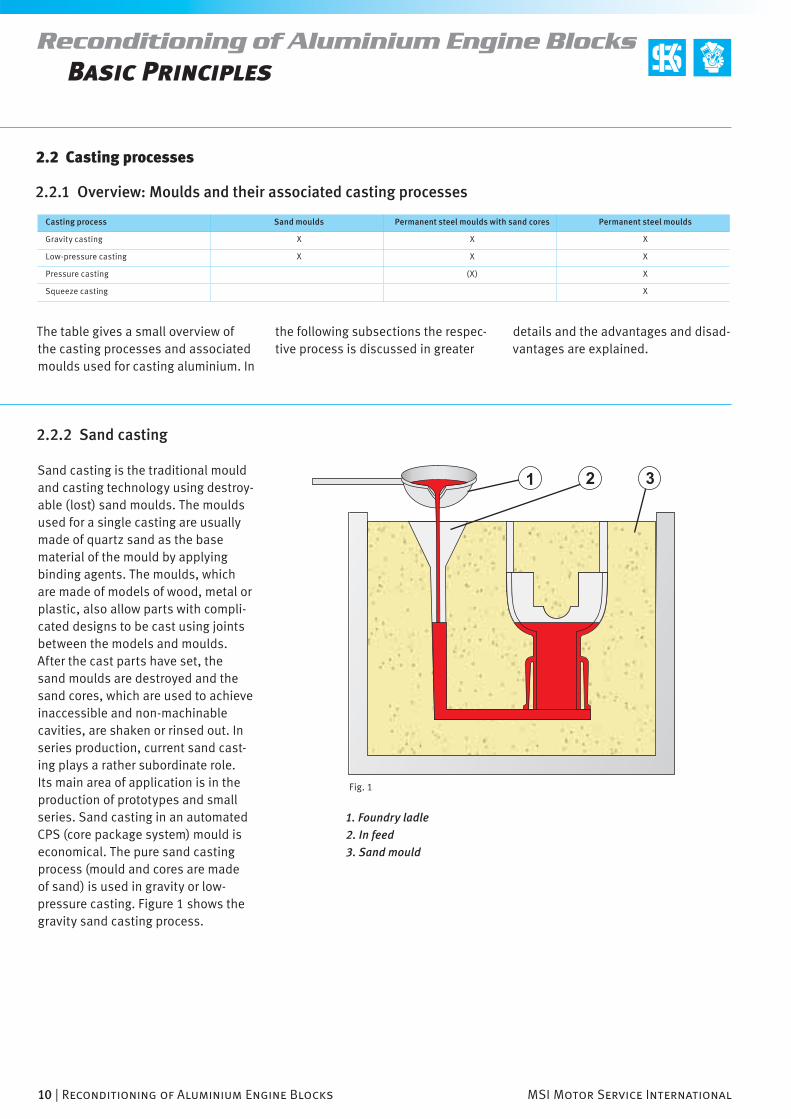
Sand casting is the traditional mould and casting technology using destroy-able (lost) sand moulds. The moulds used for a single casting are usually made of quartz sand as the base material of the mould by applying binding agents. The moulds, which are made of models of wood, metal or plastic, also allow parts with compli-cated designs to be cast using joints between the models and moulds. After the cast parts have set, the sand moulds are destroyed and the sand cores, which are used to achieve in accessible and non-machinable cavities, are shaken or rinsed out. In series production, current sand cast-ing plays a rather subordinate role. Its main area of application is in the production of prototypes and small series. Sand casting in an automated CPS (core package system) mould is economical. The pure sand casting process (mould and cores are made of sand) is used in gravity or low- pressure casting. Figure 1 shows the gravity sand casting process.
1. Foundry ladle
2. In feed
3. Sand mould

MSI Motor Service International Reconditioning of Aluminium Engine Blocks | 11
Reconditioning of Aluminium Engine BlocksBasic Principles
2.2.3 Die casting
In die casting the liquid aluminium is cast into permanent metallic moulds made of cast iron or hot-work steels. In this casting process, however, the
construction and freedom of design depend on whether production is based on gravity or low-pressure casting. Contrary to sand casting, die
casting results in a higher surface quality and improved accuracy of measurement in the cast parts.
Gravity die castingIn gravity die casting the mould is fi lled solely by the infl uence of gravity on the liquid metal at atmospheric air pressure. Casting is done manually or by partially or fully automated casting machines. This process affords suffi -cient freedom of design because cast-ing cores can be made of sand (Fig. 3). This way, setback sections or cavities that would be inaccessible for machin-ing can also be produced. Because of a faster, targeted setting of the molten metal, gravity die casting produces a more refi ned structure, a higher degree of strength and unlimited heat treatment possibilities compared to sand casting.
Fig. 2
1. Foundry ladle
2. In feed
3. Hydraulic cylinder
4. Chill
5. Chamfer edge
6. Sand core
Fig. 3

12 | Reconditioning of Aluminium Engine Blocks MSI Motor Service International
Reconditioning of Aluminium Engine BlocksBasic Principles
Fig. 1
Low-pressure die castingIn low-pressure die casting the molten metal is lifted by a relatively low over-pressure (for aluminium alloys 0.2 to 0.5 bar) into the mould and congealed under this pressure. The pressure here is actually the fi lling pressure required to convey the liquid metal in the cast-ing machine upward into the mould. The fi lling pressure is maintained until the congealing has progressed from the furthest point up to the chamfer edge of the raising tube (casting mould inlet). This congealing, which is directed in an almost ideal way, and the turbulence-free mould fi lling is an essential reason for the high quality of low-pressure cast parts. As is the case with gravity die casting, cores of sand can be used in this process as well, which allows for ample freedom in workpiece design.
1. Hydraulic cylinder
2. Steel chill
3. Rising tube
4. Casting furnace with molten metal
5. Lift table
6. Lifting device
2.2.4 High pressure die casting
In high pressure die casting the molten metal is forced into permanent moulds made of tempered hot-work steel under high pressure and at a high speed. The metal fl ows into the mould cavity under pressure. Toward the end of the mould fi lling process the pressure on the liquid metal increases to 700–1000 bar. The pres-sure is maintained while the metal is
congealing. This allows the most exact reproduction of the mould cavity com-pared to other casting processes. This produces very narrow dimensional tol-erances, acutance and a good surface quality with little additional machin-ing. The high output produces a very economical casting process. There are, however, certain disadvantages to this process. Generally a double heat
treatment with increasing strength is not possible because under circum-stances air or gas pitting trapped in the material – due to the way that the mould is force-fi lled – create problems. Current design restrictions must also be mentioned because in high pressure die casting, no current sand cores can be used for casting cavities. Current sand cores would be
MSI Motor Service International Reconditioning of Aluminium Engine Blocks | 13
Reconditioning of Aluminium Engine Blocks
Fig. 2
Basic Principles
Fig. 3
destroyed by the high casting pres-sure, which would render the cast part unusable. Casting technology, however, continues to be developed. At present sand cores that can resist the high casting pressures in pressure casting are being developed.
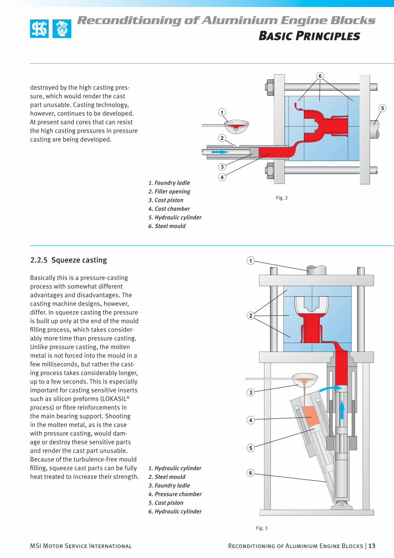
2.2.5 Squeeze casting
Basically this is a pressure-casting process with somewhat different advantages and disadvantages. The casting machine designs, however, differ. In squeeze casting the pressure is built up only at the end of the mould fi lling process, which takes consider-ably more time than pressure casting. Unlike pressure casting, the molten metal is not forced into the mould in a few milliseconds, but rather the cast-ing process takes considerably longer, up to a few seconds. This is especially important for casting sensitive inserts such as silicon preforms (LOKASIL® process) or fi bre reinforcements in the main bearing support. Shooting in the molten metal, as is the case with pressure casting, would dam-age or destroy these sensitive parts and render the cast part unusable. Because of the turbulence-free mould fi lling, squeeze cast parts can be fully heat treated to increase their strength.
1. Hydraulic cylinder
2. Steel mould
3. Foundry ladle
4. Pressure chamber
5. Cast piston
6. Hydraulic cylinder
1. Foundry ladle
2. Filler opening
3. Cast piston
4. Cast chamber
5. Hydraulic cylinder
6. Steel mould

14 | Reconditioning of Aluminium Engine Blocks MSI Motor Service International
Reconditioning of Aluminium Engine BlocksBasic Principles
Fig. 1PSA 4 Zyl. (Reihe)
Fig. 2Audi V8
2.3.1 Different types of engine block design
There are different concepts and production processes for aluminium engine blocks that compete with each other. The respective technical and
2.3 Engine block concepts
economical advantages and disadvan-tages must be weighed against each other carefully in the design of engine blocks. The following sections give
an overview of the different types of engine block construction.
Solid blocks are engine block con-structions that have neither wet cylinder liners nor a screwed bearing housing in the form of a bedplate (Fig. 1). To obtain certain surfaces or degrees of stability, solid blocks can, however, have the appropriate inserts in the cylinder bore area (grey cast iron inserts, LOKASIL® preforms) and inserts made of grey cast iron or malleable cast iron as well as fi bre reinforcements in the area of the main bearing bore. They are, however, not the latest state of the art.
Solid blocks
Two-piece blocks (with bedplate)In this type of construction the main bearing cover of the crankshaft is included in a separate bedplate (Fig. 2). The bedplate is screwed to the cylinder crankcase and has sphero cast reinforcements anchored in the aluminium in order to control the main bearing clearance better or to com-pensate for the increased, specifi c thermal expansion of the aluminium. This produces extremely rigid engine block constructions. As with solid blocks, inserts can be cast for the cylinder bore area here as well.

MSI Motor Service International Reconditioning of Aluminium Engine Blocks | 15
Reconditioning of Aluminium Engine BlocksBasic Principles
Fig. 3Porsche 6 Zyl. (Boxer)
Fig. 4Volvo 5 Zyl. (Diesel)
“Open deck” construction with individual, free-standing cylinder tubesIn this construction the water jacket is open to the face of the cylinder head and the cylinder tubes stand free within the engine housing (Fig. 3). The heat transfer from the cylinder tubes to the coolant is very even and advantageous because the coolant is distributed on all sides. The relatively large distance between the cylinders, however, has a negative effect on the length of the engine construction for engines with multiple cylinder rows. Due to the upwards open, relatively simply maintained coolant chamber, the use of sand cores can be omitted in production. Thus the engine blocks can be made using a low-pressure and well as a pressure casting process.
“Open deck” construction with cylinder tubes cast togetherA logical consequence of the reduc-tion in the length of the construction for engine blocks with free standing cylinder tubes is a reduction in the distance between the cylinders. By placing the cylinders closer together, however, the cylinder tubes must be designed to be cast together (Fig. 4). Not only does this help the length of the engine construction, but it also improves the rigidity in the upper cylinder area. This can save 60–70 mm from the length of the construc-tion of six-cylinder row engines, for example. This can reduce the wall between the cylinders to 7–9 mm. These advantages outweigh the dis-advantage of cooling without a water jacket between the cylinders.

16 | Reconditioning of Aluminium Engine Blocks MSI Motor Service International
Reconditioning of Aluminium Engine BlocksBasic Principles
Fig. 1Mercedes 4 Zyl. (Reihe)
Fig. 2PRV V6
“Closed deck” constructionIn this engine block construction, unlike the open deck construction, the cylinder deck is closed up to the water penetration openings on the side of the cylinder heads (Fig. 1). This is especially advantageous for the cylinder head sealing. This type of construction also offers advantages when an existing grey cast iron engine block is being converted to aluminium. Because the type of construction is comparable (cylinder head sealing surface), the cylinder head and cylin-der head sealing require only minor modifi cations or none.
Unlike the open deck construction, the closed deck model is naturally more diffi cult to manufacture. The rea-son is the closed water jacket and the water jacket sand core that it requires.
Also the use of sand cores makes the maintenance of smaller tolerances in the thickness of the cylinder walls more diffi cult. Closed deck engine blocks can be produced by grav-ity as well as low-pressure casting processes.
Because of the cylinder tubes that are cast together above and the greater rigidity in the upper cylinder area, this construction has greater load reserves compared to the “open deck” con-struction.
Aluminium engine blocks with wet linersThese cylinder blocks are mostly manufactured from an inexpensive aluminium alloy using high pressure die casting and equipped with wet cylinder liners made of grey cast iron. A prerequisite for this engine design is the control of an “open deck” con-struction with the sealing problems associated with it. This is a type of construction that is no longer used is the series production of engines for passenger vehicles. A typical example from the KS production line was the V6 block of the PRV (Peugeot/Renault/Volvo) engine (Fig. 2).
These engine blocks are still used today to build sports car and racing
car engines where cost is not such an issue. Here, however, no grey cast iron liners are used, but rather high-tensile, wet aluminium liners with nickel-coated cylinder sliding surfaces.
MSI Motor Service International Reconditioning of Aluminium Engine Blocks | 17
Reconditioning of Aluminium Engine BlocksBasic Principles
Fig. 4
Fig. 3
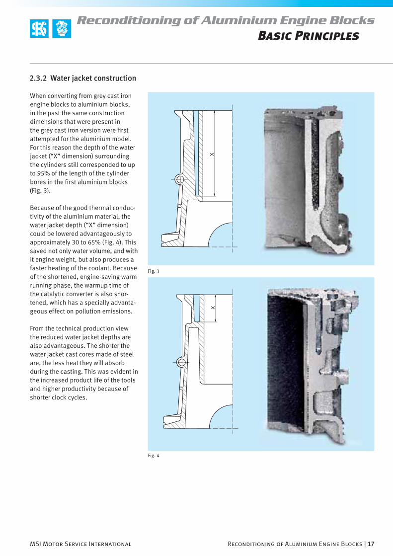
2.3.2 Water jacket construction
When converting from grey cast iron engine blocks to aluminium blocks, in the past the same construction dimensions that were present in the grey cast iron version were fi rst attempted for the aluminium model. For this reason the depth of the water jacket (“X” dimension) surrounding the cylinders still corresponded to up to 95% of the length of the cylinder bores in the fi rst aluminium blocks (Fig. 3).
Because of the good thermal conduc-tivity of the aluminium material, the water jacket depth (“X” dimension) could be lowered advantageously to approximately 30 to 65% (Fig. 4). This saved not only water volume, and with it engine weight, but also produces a faster heating of the coolant. Because of the shortened, engine-saving warm running phase, the warmup time of the catalytic converter is also shor-tened, which has a specially advanta-geous effect on pollution emissions.
From the technical production view the reduced water jacket depths are also advantageous. The shorter the water jacket cast cores made of steel are, the less heat they will absorb during the casting. This was evident in the increased product life of the tools and higher productivity because of shorter clock cycles.

18 | Reconditioning of Aluminium Engine Blocks MSI Motor Service International
Reconditioning of Aluminium Engine BlocksBasic Principles
Fig. 1
Fig. 3
Fig. 2
2.3.3. Cylinder head bolt connection
1. Force used to tighten the cylinder head fastening bolts / 2. Pressure applied by cylinder head and cylinder head gasket. /
3. Cylinder deformation (highly exaggerated) / 4. Top bolt thread / 5. Bottom bolt thread
To keep cylinder distortions to a minimum while the cylinder head is being installed, the threading ridges
– the material accumulation for the tap holes of the cylinder head bolts
– are attached to the outer wall of the engine block. A direct contact with the cylinder wall would have caused greater deformations unevenly as the bolts were being tightened. Further improvements will also produce deep located threads. Figures 1 and 2 explain the differences in the cylinder distortions produced by high and low bolt threads.
There are further possibilities by using fl ush-mounted steel nuts instead of the normal tap holes to avoid distor-tion and strength problems (especially in the case of diesel direct injection engines). In some constructions, long tie rod bolts, that are practically screwed through the cylinder deck (Fig. 3) or screwed directly to the bear-ing bridge, are used (Fig. 4).
1. Washer
2. Cylinder head bolt
3. Steel thread insert
4. Tension rod bolt
5. Main bearing cover

MSI Motor Service International Reconditioning of Aluminium Engine Blocks | 19
Reconditioning of Aluminium Engine BlocksBasic Principles
Fig. 5
Fig. 4
1. Washer
2. Tension rod bolt
3. Bearing bridge
4. Main bearing cover
2.3.4. Piston pin installation bores in the cylinder wall
When fl at (boxer) engines are being built, there are installation problems with the piston pins of one cylinder row because of their design. This is because both halves of the crank-case must be screwed together in order to install the pistons of the second cylinder row or to screw the conrods to the relative conrod bear-
ing pin. Because the crankshaft is no longer accessible after both halves of the crankcase have been screwed together, the conrods are screwed without pistons to the respective conrod bearing pins of the crankshaft, and the pistons are inserted after both crankcase halves have been screwed together. The missing piston pins are
inserted through cross-drilled bores in the lower cylinder area (Fig. 5) to connect the pistons to the conrods. The installation bores run through the cylinder sliding surfaces in an area that does not come into contact with the piston rings.

20 | Reconditioning of Aluminium Engine Blocks MSI Motor Service International
Reconditioning of Aluminium Engine BlocksBasic Principles
Fig. 1
Fig. 2
2.3.5 Crankcase ventilation openings
Newer crankcases are equipped with ventilation openings above the crank-shaft and below the cylinders (Figs. 1 and 2). Ventilation is hindered inside the crankcase when the side walls and the main bearing support con-nected to them are reduced. The ven-tilation openings allows the air below the piston that is displaced by the piston movement from the top to the bottom top dead centre to escape on the side and presses it into the place where the piston is moving directly in the direction of the top dead centre. The air is exchanged faster and more effectively because it no longer has to travel the long way around the crank-shaft. The reduced drag also pro-duces a noticeable increase in power. Depending on the distance between the cylinders and the crankshaft, the ventilation openings are either in the area of the main bearing connection below the cylinder sliding surfaces, inside the cylinder sliding surfaces or somewhere in between.

MSI Motor Service International Reconditioning of Aluminium Engine Blocks | 21
Reconditioning of Aluminium Engine BlocksBasic Principles
Fig. 3
2.4 Sliding surface technologies
The pivotal point of each aluminium engine block design is a very exact defi nition of the requirement profi le. The central component of each design is the cylinder sliding surface. Because suffi cient tribological properties cannot be realised with the current aluminium casting materials, in this respect a suitable process has to be found for each application that will pro-vide optimum strength for the cylinder sliding surfaces during production and that will also be economical.
As before, great differences still exist in the sliding surface designs of petrol and diesel engines. Although the development of aluminium sliding surfaces for petrol engines has progressed considerably, and the ALUSIL® process has also been introduced extensively in engine production, so far this has not been the case with diesel engines. Thus for diesel engines, cylinder liners made of grey cast iron still represent the norm for applications. At the moment
the development of sliding surfaces is tending toward coating cylinder sliding surfaces with iron materials. This is done either by thermal spray (plasma coating), by electric arc wire thermal spray, or PVD processes. These processes are described in greater detail in the following sections.
2.4.1 Overview of the different sliding surface technologies
Sliding Surface Technologies for Aluminium Engine Blocks
monolithic heterogeneous quasi monolithic
hypereutectic Al-Si alloy (ALUSIL®) cylinder liners or cylinder liner inserts
cast-in cylinder liner inserts
grooved cast iron liner inserts
rough cast iron cylinder liner inserts
grey cast liner inserts with outer aluminium coating
ALUSIL ®-liner inserts
SILITECH ®-cylinder liner inserts
shrunk cylinder liners
grey cast iron cylinder liners
ALUSIL ®
cylinder liners
wet cylinder liners
grey cast iron cylinder liners
ALUSIL ®
cylinder liners
aluminium cylinder liners with nickel coating
coated cylinder bores
nickel coating
chrome plating
plasma coating
electric arc wirethermal spray
TiAlN, TiN thin layer PVD coating
llocal material-engineering
laser alloy with silicon
AL matrix-bond material
(LOKASIL®)

22 | Reconditioning of Aluminium Engine Blocks MSI Motor Service International
Reconditioning of Aluminium Engine Blocks
Fig. 1
Basic Principles
Fig. 2Picture: Taylor Hobson
In the ALUSIL ® process, the entire engine housing consists of a hyper-eutectic aluminium silicon alloy. The increased silicon content, which contains 17% silicon in the most frequently used ALUSIL ® alloy (AlSi-17Cu4Mg), is typical of such a hyper-eutectic alloy.
In contrast to the hypereutectic alloy, a eutectic aluminium silicon alloy contains only 12–13% silicon. With this silicon content the saturation degree is reached. A greater silicon content will cause primary silicon crystals to form when the molten metal coagulates. This means that the silicon content that cannot be alloyed to the aluminium due to the saturation of the aluminium crystallises will be de posited in the (saturated) alu-minium silicon alloy (eutectic). A small amount of phosphorous is added to the molten metal to help the silicon crystallisation process. The silicon crystals grow around a hetero geneous aluminium phosphide nucleus. The size of the silicon crystals ranges from 20 to 70 µm. After the appropri-ate processing and exposing of these primary silicon crystals, they form the hard, wear-resistant cylinder sliding surface for the pistons and the piston rings without additional reinforcement. Figure 1 – This is an enlarged faxfi lm1 image showing a fi nished ALUSIL ® cylinder sliding surface (mechanical exposure). The prominent exposure of the crystals in the aluminium matrix can be seen clearly. The longer the coagulation process, the larger the silicon crystals become. The different cooling rates within the engine block cause silicon crystals to form in the lower cylinder area somewhat larger than in the upper cylinder area which
2.4.2 ALUSIL® cylinder sliding surfaces
1 Faxfi lm – thin mouldable transparent fi lm for transfering surface structures.
100 µm
100 µm
100 µm
100 µm
MSI Motor Service International Reconditioning of Aluminium Engine Blocks | 23
Reconditioning of Aluminium Engine BlocksBasic Principles
Fig. 3
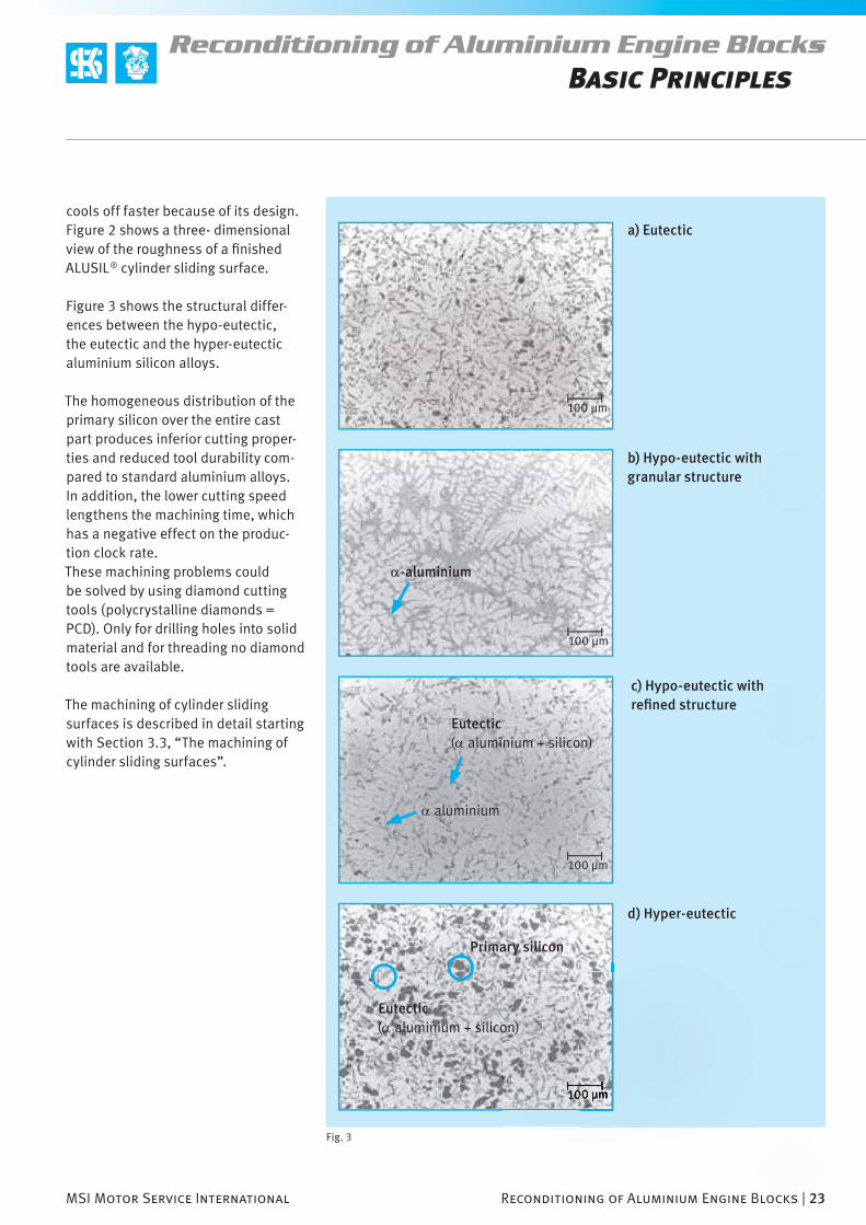
cools off faster because of its design. Figure 2 shows a three- dimensional view of the roughness of a fi nished ALUSIL ® cylinder sliding surface.
Figure 3 shows the structural differ-ences between the hypo-eutectic, the eutectic and the hyper-eutectic aluminium silicon alloys.
The homogeneous distribution of the primary silicon over the entire cast part produces inferior cutting proper-ties and reduced tool durability com-pared to standard aluminium alloys. In addition, the lower cutting speed lengthens the machining time, which has a negative effect on the produc-tion clock rate.These machining problems could be solved by using diamond cutting tools (polycrystalline diamonds = PCD). Only for drilling holes into solid material and for threading no diamond tools are available.
The machining of cylinder sliding surfaces is described in detail starting with Section 3.3, “The machining of cylinder sliding surfaces”.
a) Eutectic
α-aluminium
b) Hypo-eutectic with granular structure
α aluminium
Eutectic (α aluminium + silicon)
Primary silicon
Eutectic (α aluminium + silicon)
c) Hypo-eutectic with refi ned structure
d) Hyper-eutectic

50 : 1
20 : 1
24 | Reconditioning of Aluminium Engine Blocks MSI Motor Service International
Reconditioning of Aluminium Engine Blocks
Fig. 1
Basic Principles
2.4.3 LOKASIL ® cylinder sliding surfaces
In the LOKASIL ® process a standard pressure-cast alloy (e.g. AlSi9Cu3) is enriched locally with silicon in the area of the cylinder sliding surfaces. This is accomplished with highly porous, cylindrical silicon preforms that are inserted in the casting mould and squeezed into the engine block under high pressure in the squeeze casting process (see also Sec-tion 2.2.5, “Squeeze casting”). The alu minium alloy (900–1000 bar) is squeezed (infi ltrated) through the pores of the silicon preform under high pressure.
This way, the silicon crystals required to reinforce the cylinder sliding sur-face are purposely present only in the area of the cylinder sliding surfaces. This local silicon enrichment produces sliding surface properties equivalent to those of the LOKASIL ® process. The lower silicon content in the aluminium alloy produces engine blocks that can be machined very well except for the cylinder sliding surfaces, contrary to the LOKASIL ® process. Figure 1 shows a cross-section of an engine block manufactured using the LOKASIL ® process with microscopic enlargements of 20 or 50 times. It is easy to see the silicon enrichment in the area of the cylinder sliding surfaces (darker area).
The silicon preforms (Fig. 2) come in two different versions. A distinc-tion is made between LOKASIL ® I and LOKASIL ® II. Both versions are fi rst baked in a furnace before being
mately 5–7% fi bre and 15% silicon after being cast into the engine block. With LOKASIL ® II, the silicon portion is approximately 25% and the inorganic binder is about 1%. With LOKASIL ® I the size of the silicon particles is
poured into the engine block. In the process a synthetic resin bond is burned off and an inorganic binder is activated to hold the silicon crystals together until casting.
With LOKASIL ® I, the prepared tool combination will contain approxi-
MSI Motor Service International Reconditioning of Aluminium Engine Blocks | 25
Reconditioning of Aluminium Engine BlocksBasic Principles
Fig. 5
Fig. 2
Fig. 3 Fig. 4
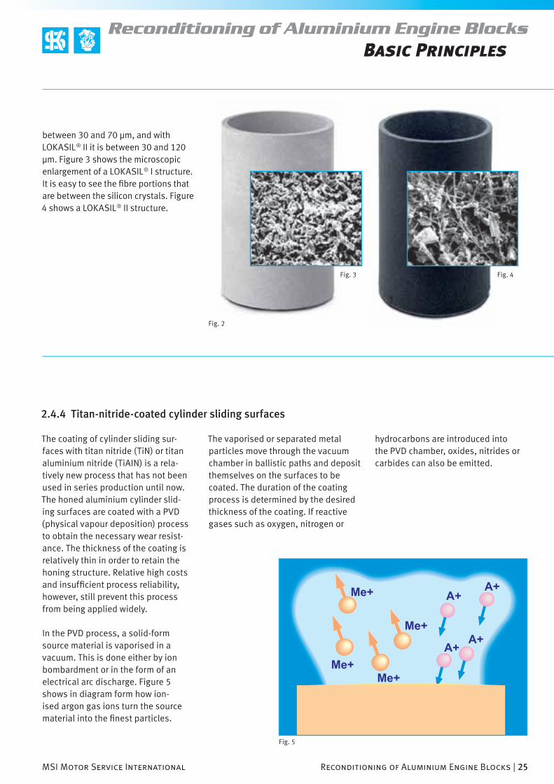
between 30 and 70 µm, and with LOKASIL ® II it is between 30 and 120 µm. Figure 3 shows the microscopic enlargement of a LOKASIL ® I structure. It is easy to see the fi bre portions that are between the silicon crystals. Figure 4 shows a LOKASIL ® II structure.
2.4.4 Titan-nitride-coated cylinder sliding surfaces
The coating of cylinder sliding sur-faces with titan nitride (TiN) or titan aluminium nitride (TiAIN) is a rela-tively new process that has not been used in series production until now. The honed aluminium cylinder slid-ing surfaces are coated with a PVD (physical vapour deposition) process to obtain the necessary wear resist-ance. The thickness of the coating is relatively thin in order to retain the honing structure. Relative high costs and insuffi cient process reliability, however, still prevent this process from being applied widely.
In the PVD process, a solid-form source material is vaporised in a vacuum. This is done either by ion bombardment or in the form of an electrical arc discharge. Figure 5 shows in diagram form how ion-ised argon gas ions turn the source material into the fi nest particles.
The vaporised or separated metal particles move through the vacuum chamber in ballistic paths and deposit themselves on the surfaces to be coated. The duration of the coating process is determined by the desired thickness of the coating. If reactive gases such as oxygen, nitrogen or
hydrocarbons are introduced into the PVD chamber, oxides, nitrides or carbides can also be emitted.

26 | Reconditioning of Aluminium Engine Blocks MSI Motor Service International
Reconditioning of Aluminium Engine BlocksBasic Principles
Fig. 1
Fig. 2
2.4.5 Nickel-coated cylinder sliding surfaces
In the past cylinder sliding surfaces were coated for a time with a nickel silicon dispersion layer (Ni-SiC) to achieve the necessary wear resistance by galvanising it onto the fi nely machined cylinder sliding surface. galnikal® and Nikasil® became known as brand names for this process. The average thickness of the nickel coating is between 10 and 50 µm. To improve the wear resistance, hard phases of silicon carbide (7–10% volume) are embedded in the coating. The size of the grains of silicon car-bide is between 1–3 µm. Inexpensive aluminium alloys such as silumin® (e.g. AlSi9Cu3) can be used as base material for engine blocks. Figure 2 shows a microscopic enlargement of a cross-section of a nickel-coated cylinder sliding surface.
Because of the uneven thickness of the nickel coating that occurs in the gal-
vanising process, the cylinder sliding surfaces still have to be smoothed and shaped by a normal honing process after the nickel coating. Compared to the grey cast iron liners, nickel coating is relatively smooth and does not have any graphite cores in which lubri-cation oil can be deposited. Therefore the concluding honing operation is especially important to produce oil distribution channels and to improve the oil retention volume of the cylinder sliding surface.
Nickel coatings require high invest-ments in galvanisation systems and decontamination units for the pre-treatment baths. Last but not least, the disposal of the nickel sludge that accumulates has a negative effect on the production costs. Nickel coating has been used mainly in the series production of single cylinders. Multi-cylinder blocks with nickel coating, on
the contrary, are used only on a case-by-case basis as a solution in series production. There have been produc-tion problems with casting porosity in the cylinder surface that have caused the coatings to become detached. In the past there have also been problems associated with sulphurous fuel with frequent short- distance driving. In the case of engines that seldom or never reached their operating temperatures, the short-distance driving caused condensates to be formed that pro-duced sulphurous acids together with sulphur contents from the combustion of sulphurous acids. These acidic combustion products have resulted in corrosion, the detaching of the coating mentioned, and fi nally a departure from nickel coated cylinder running surfaces in the production of engines for passenger car series.
Unlike the ALUSIL® process, a rege-neration of the cylinder bores in the reconditioning process – including a new nickel coating – is possible only at a great cost and with great diffi cu-lty. Without an appropriate special operation, this is almost impossible. Figure 1 shows a fi nned aluminium cylinder of a motorcycle engine with galnikal® coating.
MSI Motor Service International Reconditioning of Aluminium Engine Blocks | 27
Reconditioning of Aluminium Engine Blocks
Fig. 3
Fig. 4
Basic Principles
Fig. 5
2.4.6 Iron-based plasma vaporisation coating
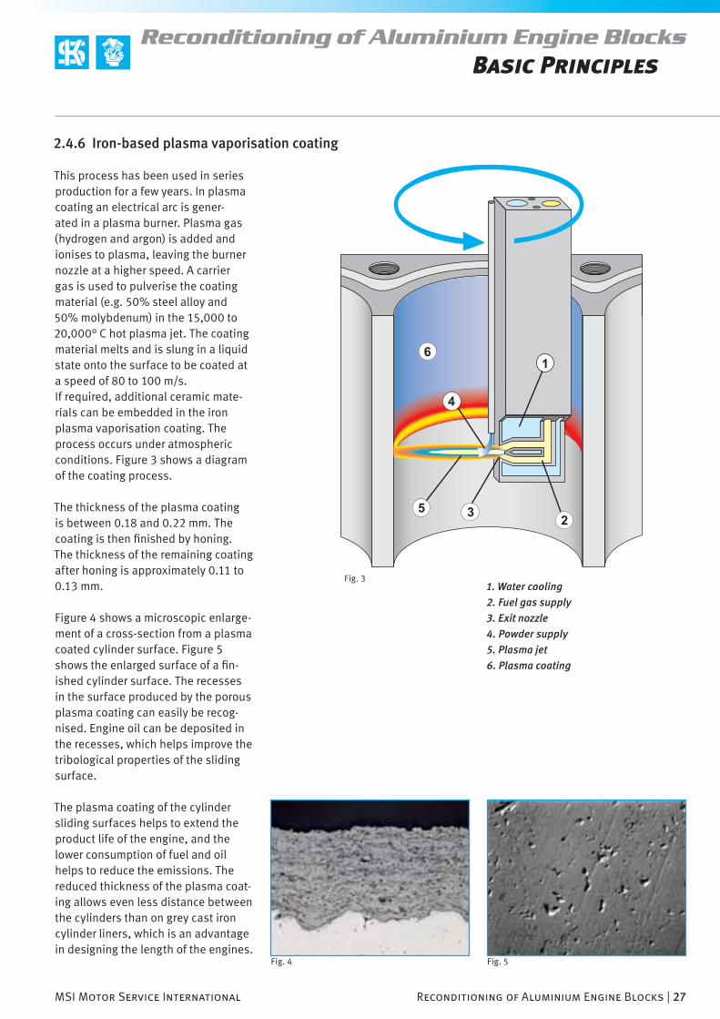
This process has been used in series production for a few years. In plasma coating an electrical arc is gener-ated in a plasma burner. Plasma gas (hydrogen and argon) is added and ionises to plasma, leaving the burner nozzle at a higher speed. A carrier gas is used to pulverise the coating material (e.g. 50% steel alloy and 50% molybdenum) in the 15,000 to 20,000° C hot plasma jet. The coating material melts and is slung in a liquid state onto the surface to be coated at a speed of 80 to 100 m/s.If required, additional ceramic mate-rials can be embedded in the iron plasma vaporisation coating. The process occurs under atmospheric conditions. Figure 3 shows a diagram of the coating process.
The thickness of the plasma coating is between 0.18 and 0.22 mm. The coating is then fi nished by honing. The thickness of the remaining coating after honing is approximately 0.11 to 0.13 mm.
Figure 4 shows a microscopic enlarge-ment of a cross-section from a plasma coated cylinder surface. Figure 5 shows the enlarged surface of a fi n-ished cylinder surface. The recesses in the surface produced by the porous plasma coating can easily be recog-nised. Engine oil can be deposited in the recesses, which helps improve the tribological properties of the sliding surface.
The plasma coating of the cylinder sliding surfaces helps to extend the product life of the engine, and the lower consumption of fuel and oil helps to reduce the emissions. The reduced thickness of the plasma coat-ing allows even less distance between the cylinders than on grey cast iron cylinder liners, which is an advantage in designing the length of the engines.
1. Water cooling
2. Fuel gas supply
3. Exit nozzle
4. Powder supply
5. Plasma jet
6. Plasma coating
28 | Reconditioning of Aluminium Engine Blocks MSI Motor Service International
Reconditioning of Aluminium Engine Blocks
Fig. 1
Basic Principles
2.4.7 Laser alloyed cylinder sliding surfaces
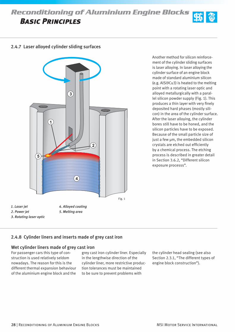
1. Laser jet
2. Power jet
3. Rotating laser optic
2.4.8 Cylinder liners and inserts made of grey cast iron
grey cast iron cylinder liner. Especially in the lengthwise direction of the cylinder liner, more restrictive produc-tion tolerances must be maintained to be sure to prevent problems with
the cylinder head sealing (see also Section 2.3.1, “The different types of engine block construction”).
Wet cylinder liners made of grey cast ironFor passenger cars this type of con-struction is used relatively seldom nowadays. The reason for this is the different thermal expansion behaviour of the aluminium engine block and the
Another method for silicon reinforce-ment of the cylinder sliding surfaces is laser alloying. In laser alloying the cylinder surface of an engine block made of standard aluminium silicon (e.g. AlSi9Cu3) is heated to the melting point with a rotating laser optic and alloyed metallurgically with a paral-lel silicon powder supply (Fig. 1). This produces a thin layer with very fi nely deposited hard phases (mostly sili-con) in the area of the cylinder surface. After the laser alloying, the cylinder bores still have to be honed, and the silicon particles have to be exposed. Because of the small particle size of just a few µm, the embedded silicon crystals are etched out effi ciently by a chemical process. The etching process is described in greater detail in Section 3.6.2, “Different silicon exposure processs”.
4. Alloyed coating
5. Melting area
MSI Motor Service International Reconditioning of Aluminium Engine Blocks | 29
Reconditioning of Aluminium Engine Blocks
Fig. 2 Fig. 3
Basic Principles
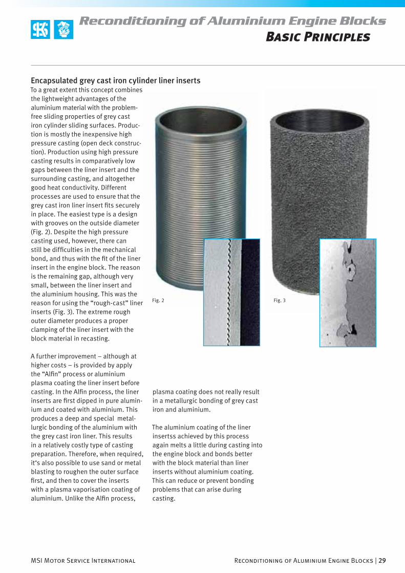
Encapsulated grey cast iron cylinder liner insertsTo a great extent this concept combines the lightweight advantages of the aluminium material with the problem-free sliding properties of grey cast iron cylinder sliding surfaces. Produc-tion is mostly the inexpensive high pressure casting (open deck construc-tion). Production using high pressure casting results in comparatively low gaps between the liner insert and the surrounding casting, and altogether good heat conductivity. Different processes are used to ensure that the grey cast iron liner insert fi ts securely in place. The easiest type is a design with grooves on the outside diameter (Fig. 2). Despite the high pressure casting used, however, there can still be diffi culties in the mechanical bond, and thus with the fi t of the liner insert in the engine block. The reason is the remaining gap, although very small, between the liner insert and the aluminium housing. This was the reason for using the “rough-cast” liner inserts (Fig. 3). The extreme rough outer diameter produces a proper clamping of the liner insert with the block material in recasting.
A further improvement – although at higher costs – is provided by apply the “Alfi n” process or aluminium plasma coating the liner insert before casting. In the Alfi n process, the liner inserts are fi rst dipped in pure alumin-ium and coated with aluminium. This produces a deep and special metal-lurgic bonding of the aluminium with the grey cast iron liner. This results in a relatively costly type of casting preparation. Therefore, when required, it‘s also possible to use sand or metal blasting to roughen the outer surface fi rst, and then to cover the inserts with a plasma vaporisation coating of aluminium. Unlike the Alfi n process,
plasma coating does not really result in a metallurgic bonding of grey cast iron and aluminium.
The aluminium coating of the liner insertss achieved by this process again melts a little during casting into the engine block and bonds better with the block material than liner inserts without aluminium coating. This can reduce or prevent bonding problems that can arise during casting.

30 | Reconditioning of Aluminium Engine Blocks MSI Motor Service International
Reconditioning of Aluminium Engine Blocks
Fig. 1
Fig. 2
Basic Principles
2.4.9 Encapsulated aluminium liner inserts (ALUSIL®, Silitec®)
In addition to the manufacturing of monolithic engine blocks from ALUSIL® material, engine blocks can also be manufactured with aluminium liner inserts with high silicon contents (ALUSIL®, Silitec®). In this process, the silicon enrichment required for cylinder reinforcement is present only in the area of the cylinder sliding surfaces. The rest of the engine block consists of a standard aluminium silicon alloy (e.g. AlSi9Cu3).
Spray-compacted encapsulated liner insertsThis is a still relatively new process for manufacturing aluminium liner inserts with high silicon contents (Silitec®). The liner material required for casting is produced in what is referred to as a “spray compaction” process. For purposes of simplicity and clarity, the term “Silitec®” is used in the following text. In a chamber a molten aluminium mass is fi nely atomised by a carrier gas (nitrogen) and the workpiece is built up layer by layer (Fig. 1). The shape of the spray pattern determines the later shape of the semi-fi nished product. In principle, this process can be used to manufacture pipes, discs, rods or metal plates in one step. Technically, spray compacting lies between sintering and mould casting in the production process. Contrary to conventional casting materials, it is possible to manufacture materials with unusual compounds similarly to sintering. In this process the silicon content can be as much as 25%. The result is very fi ne structure with homo-geneous element and phase distribu-tions and with good malleability.
The raw material obtained this way in a round shape is converted in an extru-sion process to pipes, which are then sawed into pieces as inserts for the engine block (Fig. 3). To improve the bonding, the surfaces of the liners are
roughened by blasting before casting. Faster high pressure casting process is used because of the risk of melting the Silitec® liners.
The cylinder bores are then machined like the other aluminium silicon cylinder sliding surfaces. The sili-con crystals, which have a size of 4–10 µm, are distributed very fi nely throughout the structure of the inserts (Fig. 2). Because the particles are very small, the silicon crystals exposure places special demands on the fi nish-ing of the cylinder sliding surfaces. Therefore, in series production etch-ing exposure with caustic soda is preferred for engine blocks manufac-tured using this process.
1. Crucible
2. Molten metal
3. Ring nozzle
4. Spray booth
5. Spray pattern
6. Workpiece
7. Rotary table
gleichmäßige Verteilung der Siliziumkristalle

MSI Motor Service International Reconditioning of Aluminium Engine Blocks | 31
Repair and machining procedures

32 | Reconditioning of Aluminium Engine Blocks MSI Motor Service International
Reconditioning of Aluminium Engine BlocksRepair and machining procedures
With increasing frequency the work-shop or also the reconditioning shop must acknowledge that in the develop-ment of vehicle components provision was not made by the designer for repair and overhaul for technical or cost reasons. Many modules or com-ponents have the same destiny and land in the scrap pile due to the lack of available parts, even for smaller errors, although they might be able to be repaired with the appropriate effort and know-how.
3.1 Repair considerations and recommendations
This trend can also be noticed in the development of engine blocks. Today many new techniques are used for cylinder machining and sliding surface coating that cannot be reproduced in the reconditioning fi eld due to the lack of available production facilities and fi nishing machines.
With the repair and replacement solu-tions described below, the appropriate equipment, and the experience and
skill of the engine reconditioner, a majority of aluminium blocks can, how-ever, be brought to a functioning and technically correct state again.
3.1.1 Determining and distinguishing between the different sliding surface technologies
Diesel enginesWith diesel engines it can still be assumed – at least for now – that the cylinder sliding surfaces consist either of grey cast iron liner inserts or are coated with an iron material in a plasma vaporisation or electric arc wire thermal spray. At present the appropriate ALUSIL® or equivalent processes are also being tested and developed further. This has already produced many promising results. The use of aluminium silicon sliding surfaces in diesel engines is, however, not anticipated in series production in the short term because of higher technical requirements with respect to the wear resistance of the cylinder sliding surfaces and the rigidity of the engine housing (mainly cylinder peak pressure).
Petrol enginesIn petrol engines, in the case of aluminium engine blocks the ALUSIL® process has enjoyed greater popu-larity. The machining and exposure processes have been developed to the extent that the potential of the aluminium engine block can be fully exploited in the meantime. There are, however, still challenges for several petrol direct fuel injection engines for which one is still trying to optimise the tribological properties and thus the wear resistance of the cylinder sliding surface. Inline or V-type engines that were produced in the mid nineties can still have a nickel or chrome coating on the cylinder sliding surface. Above all, single cylinder engines, such as those used in motor-cycles, were given nickel or chrome coatings.
In case of doubt, a screw driver or similar object can be used to deter-
mine whether the sliding surface is coated (nickel or chrome) or whether it is made of aluminium silicon (ALUSIL®, LOKASIL®, Silitec®). If it is an uncoated aluminium silicon cylinder sliding surface, it will be easy to penetrate the surface and leave a scratch with the tip of a screwdriver (it is recom-mended that the test be made in an area of the cylinder sliding surface that has not come into contact with the piston rings). If it is a nickel or chrome coated cylinder, the blade will not be able to penetrate the surface and will only be able to make slight marks, if any, on the surface. Another feature of nickel coated cylinder sliding surfaces is the more yellow-ish colour of the nickel as compared to aluminium. Furthermore, honing marks will be present in the nickel coated cylinder sliding surface. This is because a follow-up honing opera-tion of the cylinder sliding surfaces is
MSI Motor Service International Reconditioning of Aluminium Engine Blocks | 33
Reconditioning of Aluminium Engine BlocksRepair and machining procedures
Fig. 1 Fig. 2
still necessary after the nickel coating. With aluminium silicon sliding surfaces, on the other hand, little or no honing marks should be detectable, if the slid-ing surface is still in its original state.
In summary, it can be said that wher-ever the scratch test is positive and a scratch is made, an aluminium silicon sliding surface is present, and drilling and machining are possible using the ALUSIL® process. Furthermore, an ALUSIL® liner can be inserted if neces-sary because of a damaged sliding surface (see Section 3.2.2, “Inserting cylinder liners in aluminium blocks”).
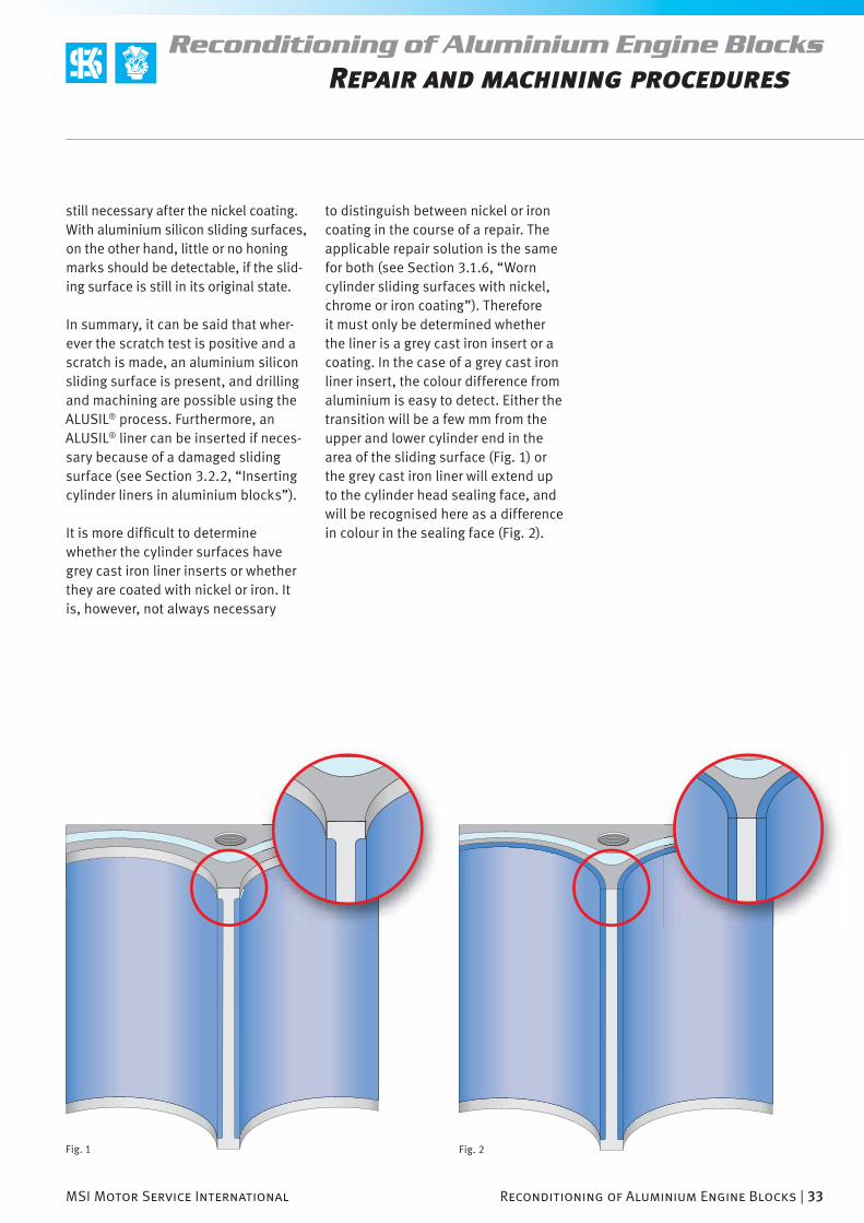
It is more diffi cult to determine whether the cylinder surfaces have grey cast iron liner inserts or whether they are coated with nickel or iron. It is, however, not always necessary
to distinguish between nickel or iron coating in the course of a repair. The applicable repair solution is the same for both (see Section 3.1.6, “Worn cylinder sliding surfaces with nickel, chrome or iron coating”). Therefore it must only be determined whether the liner is a grey cast iron insert or a coating. In the case of a grey cast iron liner insert, the colour difference from aluminium is easy to detect. Either the transition will be a few mm from the upper and lower cylinder end in the area of the sliding surface (Fig. 1) or the grey cast iron liner will extend up to the cylinder head sealing face, and will be recognised here as a difference in colour in the sealing face (Fig. 2).

34 | Reconditioning of Aluminium Engine Blocks MSI Motor Service International
Reconditioning of Aluminium Engine BlocksRepair and machining procedures
Fig. 1
3.1.2 Availability of suitable repair pistons
An important criterion for selecting the repair process is the availability of suitable repair pistons. In principle, it must fi rst be determined whether pistons are available for the engine to be reconditioned, and if so, which. No oversized pistons are available – at least not from the engine manufac-turer – for cylinder sliding surfaces that have been coated or laser-alloyed afterwards. Engine manufacturers usually assume that such engines will not be able to be repaired due to the lack of suitable repair and coating equipment.
In the ALUSIL®, LOKASIL® and Silitec® concepts, and with grey cast iron liner inserts, redrilling to the next oversize is possible, at least in theory. Because with these techniques there is no cylinder coating, a material surface will be ready for fi nishing after the redrilling. The only requirement for
redrilling is the availability of over-sized pistons. There is no guarantee that they will be available as replace-ment parts. Interest on the part of engine and piston manufacturers in offering replacement pistons is surely greater for engines that are used more frequently and produced in larger quantities than for high-end market large volume engines that in part are
manufactured only in small quanti-ties. In other words, the availability of oversized pistons is dictated by their demand and sales potential.
3.1.3 Irreparable aluminium engine blocks?
One renowned vehicle manufacturer advises that certain engine blocks must be replaced completely if the bearing caps of the main crankshaft bearings are opened. By relieving the pressure from the bolts, the internal structure would expand, which would produce distortions in the the main bearing center line. Therefore the manufacturer in question still pro-vides the engine block, the crank-shaft, the main bearing bolts, etc., as a complete assembly unit. Individual parts for this engine block are not listed in the spare parts catalogue of the engine manufacturer, neither are they supplied.
We pass on this statement without any judgement because we know that the engine reconditioning shops have competent specialists that consider it a special challenge to be able to offer their customers a technically perfect and economically viable engine recon-ditioning.
The quality demands for engines to be reconditioned are surely not as high as those of a series production, for example. For a supplier of engine blocks for series vehicles, a distortion of 5 µm can present a major problem, whereas the engine reconditioner frequently cannot measure this kind of small deviations with the instru-
ments available to him, or if so, only approximately. In case of doubt, here as well, “the proof of the pudding is in the eating”. After the crankshaft has been removed and the bearing cover has been screwed back on, it will not take much time to determine the extent of the distortions of the main bearing center line. Generally it can be said that the distortions of the main bearing centerline must be less than the main bearing clearance.

MSI Motor Service International Reconditioning of Aluminium Engine Blocks | 35
Reconditioning of Aluminium Engine BlocksRepair and machining procedures
Fig. 2
3.1.4 When are repair cylinder liners recommended?
If only a single cylinder bore or sliding surfaces of an engine block is dam-aged, for example, due to valve or piston damage, it is recommended that a cylinder liner be inserted only in the damaged cylinder. A complete renovation and reconditioning of all cylinders of an engine block by using repair liners is less recommended due to the cost of the repair and mate-rial. This applies to aluminium silicon sliding surface techniques as well as to the nickel or iron coated cylinder sliding surfaces. The redrilling of aluminium silicon sliding surfaces that can be reconditioned is always preferable to inserting repair liners. Inadvertent distortions and debilita-tion of the engine block caused by a
repair cannot always be ruled out. The walls between the cylinders are often designed to be very thin. Often the cylinder wall (Fig. 2) is only 5–7 mm wide. If liners are inserted in cylinders directly adjacent to each other, only a very thin wall will remain between the cylinder bores to be reconditioned. In certain cases, this could have a negative impact on the stability of the engine. From a technical point of view
it is much better to retain the good monolithic properties of the engine block as much as possible than to intentionally create a heterogeneous bond. It is better to repair “as much as necessary” than “as much as pos-sible”.

36 | Reconditioning of Aluminium Engine Blocks MSI Motor Service International
Reconditioning of Aluminium Engine BlocksRepair and machining procedures
Damaged aluminium silicon cylinder sliding surfacesFor damaged cylinder sliding surfaces that were manufactured using the ALUSIL®, LOKASIL®, Silitec® or com-parable process (laser alloy), cylinder sleeves (castings) made of ALUSIL® alloy (AlSi17Cu4Mg) are available in two different sizes from the KS product range (see Section 3.2.4.
“Manufacturing the necessary cylinder liners”). The material composition of the ALUSIL® castings is identical to the composition of the original engine blocks manufactured using the ALUSIL® process.
The difference in the size of the particles of primary silicon crystals formed to those of LOKASIL® and Silitec® is of less importance to the
reconditioning and sliding properties. In the above mentioned process, the size of the silicon particles varies in the production for technical reasons. Generally, larger silicon crystals are more advantageous for fi nishing (hon-ing and relieves) and cannot break off from the cylinder wall so easily. The very small size of the silicon particles in the Silitec® liner inserts is a result of the production process (spray compaction) and the subsequent forming process required (extrusion moulding). As larger particles would decrease the pliability, the intended size of the silicon particles is consid-ered a compromise between mallea-bility and suitability for fi nishing. Thus the insertion of ALUSIL® liners in an
engine block manufactured using the Silitec® process represents a techni-cally sound repair solution.
The manner in which the neces-sary liners are produced, inserted and machines is described in detail starting with Section 3.2, “Installing aluminium and grey cast iron cylinder liners”.
3.1.6 Worn nickel, chrome or iron coated cylinder sliding surfaces
This type of cylinder sliding surface cannot be reconditioned by redrilling to an oversize diameter. The coating of the sliding surface is very thin and would be eliminated completely by redrilling. Recoating can be performed only by specialised businesses that have the appropriate equipment to reapply a nickel coating to individual cylinders (e.g. for motorcycles). For multi-cylinder engine blocks it is almost impossible to fi nd a business that is able to perform such jobs. For iron coatings (plasma vaporisation
coating, manifestations of electric arc wire) no businesses at all are known that would be in a position to recoat individual engine blocks.
Therefore, for damaged cylinder slid-ing surfaces we always recommend the repair of the damaged cylinder bores. Whether it would make sense to furnish such an engine with grey cast iron liners completely depends on the cost and also on the intended result. Therefore, a costly, complete installation of liners in engine blocks
3.1.5 Worn and damaged aluminium silicon cylinder sliding surfaces
is described in detail starting with Section 3.3, The machining of alumin-ium cylinder sliding surfaces“.
Worn aluminium silicon cylinder sliding surfacesCylinders in engines with aluminium silicon cylinder sliding surfaces (ALUSIL®, LOKASIL®, Silitec® etc.) can be reconditioned the same way as grey cast iron. In other words, the
engine block can be restored to a functioning state with feasible time and material costs by redrilling and honing to the next oversize diam-eter. The machining of the cylinders
that are still available is less advis-able. In the case of aluminium engines of older vehicles from collectors for which engine blocks are no longer available, the installation of a com-plete set of grey cast iron liners may be the only possibility to salvage the engine block and to make the vehicle roadworthy again.

MSI Motor Service International Reconditioning of Aluminium Engine Blocks | 37
Reconditioning of Aluminium Engine BlocksRepair and machining procedures
Note
Here it should also be added that in the case of the above mentioned coatings, only grey cast iron liners can be considered as replacements. ALUSIL® liners cannot be used because iron-coated (lately also plastic-coated) pistons are required for ALUSIL® cylinder sliding surfaces. The pistons available for the above mentioned engines do not have the appropriate coating, which rules out a change to ALUSIL® cylinder sliding surfaces. It is not possible to coat the existing pistons afterwards.
Recommendation
Because of the changing thermal expansion behaviour when grey cast iron liners are used in previously coated cylinder bores (the grey cast iron liners heat up somewhat more slowly), it‘s recommended to increase the piston installation clearance by 0.01 mm to 0.02 mm. The diameters of the cylinder bores provided must be increased by this amount.
3.1.7 Damaged laser alloyed cylinder sliding surfaces
Here the same applies as for iron-coated cylinder sliding surfaces. Redrilling to an oversized diameter is not possible because the silicon alloy coating is too thin. For this reason, oversized pistons are not available.
Since these cylinder sliding surfaces are of aluminium silicon, and the pis-tons and rings – as with the ALUSIL® process – slide over exposed, promi-nent silicon crystals, the cylinders can be repaired by installing ALUSIL®
liners. This way the diameters of the cylinders can be retained and standard pistons can be installed.

38 | Reconditioning of Aluminium Engine Blocks MSI Motor Service International
Reconditioning of Aluminium Engine BlocksRepair and machining procedures
Fig. 1
3.1.8 Determining the existing roughness parameters of cylinder sliding surfaces
To determine the quality of the honing, the cylinder sliding surfaces can be checked with a roughness tester after fi nishing. Due to the number of differ-ent engines, it is not possible within the scope of this brochure to provide comparison data for each engine. We are sure that everyone realises that the engine manufacturers do not divulge their production data. For this reason, only guidelines can be given in the machining part starting with Section 3.3 “Machining aluminium cyl-
inder sliding surfaces”. But any engine reconditioner with a roughness tester (see MSI catalogue “tools and test equipment”) can measure the sliding surfaces of each engine block to be reconditioned before starting the job. Here the measurement must neces-sarily be taken from an upper or lower area of the cylinder end that does not came into contact with the piston rings. The data acquired in this man-ner should be suffi ciently accurate for the repair. Whether the measured
values can be achieved by the repair will ultimately depend on the equip-ment available and on the engine reconditioner and his experience.

MSI Motor Service International Reconditioning of Aluminium Engine Blocks | 39
Reconditioning of Aluminium Engine BlocksRepair and machining procedures
3.1.9 Overview of repair possibilities
The following overview explains the types of repairs that are possible from a purely technical point of view, simplifi ed once again in graphs and charts. Whether one repair or the other is economically feasible will depend on the extent of the repair and local labour costs, and must be considered separately.
Fig. 2
Grey cast iron liner inserts
Reconditioning ofone cylinder
Yes No
Reconditioning ofall cylinders
are oversized pistons available?
Redrilling and and honing to an oversize diameter
Aluminium-silicon cylinder sliding sur-faces ALUSIL®, LOKASIL®, Silitec® etc.
Cylinder sliding surface coatings of iron, nickel, chrome base
Repair ofone cylinder
Installation ofa repair liner
Redrilling and honing to standard cylinder diameter
Repair ofall cylinders
Installation of repair liners
For grey cast liner insertsis it feasible???

40 | Reconditioning of Aluminium Engine Blocks MSI Motor Service International
Reconditioning of Aluminium Engine BlocksRepair and machining procedures
Fig. 1
3.2.1 Cylinder liners for grey cast iron engine blocks
This section describes how to install dry grey cast iron liners in grey cast iron engine blocks or how to replace them. Here there are some differences from the following chapters which deal with the insertion of aluminium or grey cast iron liners in aluminium engine blocks.
There are essentially two types of dry cylinder liners that are used in grey cast iron engine blocks. One version is referred to as a “slip fi t” liner, and the other a “press fi t” liner. Unlike aluminium blocks, from the outset the engine manufacturer has made provision for reconditioning by replac-ing the cylinder liners. Both types of liners are available from the engine manufacturer or on the open parts market.
The name itself explains the way in which these liners are installed. The construction is the same for both liners. Both versions have an outside diameter that is manufactured to size and often a liner fl ange in the area of the cylinder head mounting surface. The only difference – without taking into account the dimensions – is that with press fi t liners the cylinder sliding surfaces must still be fi nished
3.2 Installing aluminium and grey cast iron cylinder liners
(honed) after liner fi tment, while the slip fi t liners are already fi nished and honed.
The advantage of both types of con-struction is that engine blocks can be reconditioned again and again by installing new cylinder liners. The slip fi t version can be installed in the workshop by any mechanic even with-out the support of machines.

MSI Motor Service International Reconditioning of Aluminium Engine Blocks | 41
Reconditioning of Aluminium Engine BlocksRepair and machining procedures
Slip fi t cylinder linersCompared to the cylinder counter-bores, these liners have a slightly smaller diameter. Because of the resulting installation clearance of
–0.01 to 0.03 mm, the liners can be installed and removed manually without much force. With this type of design the liner fl ange is absolutely necessary to secure the liner in the
intended position inside the engine block during engine operation. The liner fl ange is clamped down in the engine block and fi xed in an axial direction by the surface pressure of the cylinder head gasket. The disad-vantages of the slip fi t liner are the low clearance between the cylinder liner and the liner counterbore and the
Press fi t cylinder linersCompared to the cylinder counter-bores, press fi t cylinder liners have a slightly larger outside diameter. Because of an overlap of –0.03 to 0.08 mm (depending on the diameter of the liner), the liners have to be pressed cold into the engine block by a press. Because of the pressure used to force-fi t the liners into the engine block, the liners can become slightly oval and uneven during instal-lation. To take this into account, the cylinder liners come with a smaller inside diameter of approximately
1 mm (semi-fi nished) and must still be adjusted to size by drilling and honing after press fi tting. Because this kind of liner has a press fi t inside the engine block, a liner fl ange is not absolutely necessary, or is not provided to fi x the liner in the engine block for some engine designs.
But in the case of press fi t liners with a liner fl ange we recommend that it be retained. Especially in critical oper-ating situations, when the piston is seized inside the cylinder, the surface
resulting, somewhat reduced, thermal transfer between the liner and the engine block.
pressure on the outside diameter of the liner is often not suffi cient to hold the liner in position. It is pulled downward by the frictional grip of the piston when it is being seized and crushed properly by the crank web of the crankshaft.

42 | Reconditioning of Aluminium Engine Blocks MSI Motor Service International
Reconditioning of Aluminium Engine BlocksRepair and machining procedures
Compared to the aluminium material of the engine block, grey cast iron liners have a lower specifi c thermal expansion. The grey cast iron liners will expand only about half as far during operation as the surround-ing aluminium engine block. For this reason the overlap (press fi t) in the aluminium engine block must be greater than in a grey cast iron engine block. Because of the greater overlap and the reduced strength of the alu-minium engine blocks, the grey cast iron liners must not be pressed in. The
3.2.2 Installing cylinder liners in aluminium engine blocks
pressure required for pressing would ruin the engine block under certain circumstances.
Aluminium liners do have the same thermal expansion coeffi cient as an aluminium engine block, but because of their reduced strength would be severely deformed or destroyed during press fi tting. Furthermore, aluminium cylinder liners would be seized immediately in the cylinder counterbore due to the surface pres-sure required. The pressure required
for press fi tting would increase dramatically and the liner and the engine block would be destroyed.
When repair liners made of aluminium or grey cast iron are installed in an aluminium engine block, they must basically be inserted into the engine block by the shrinking process.
Slip fi t versions of liners such as those often used in grey cast iron engine blocks cannot be used in aluminium engine blocks at all because of stress problems. Generally, press fi tting of grey cast iron and aluminium cylinder liners is not possible in aluminium engine blocks.
Note!
Fig. 1
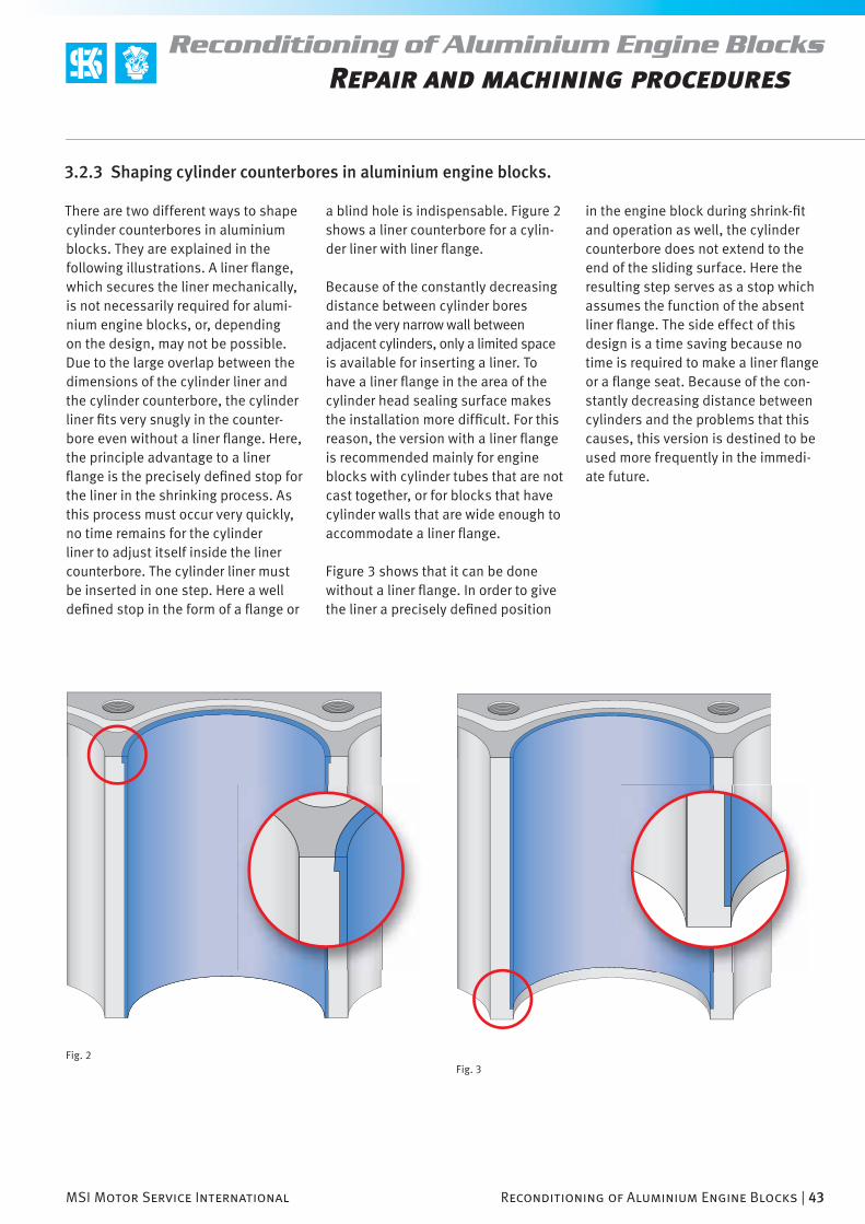
MSI Motor Service International Reconditioning of Aluminium Engine Blocks | 43
Reconditioning of Aluminium Engine BlocksRepair and machining procedures
3.2.3 Shaping cylinder counterbores in aluminium engine blocks.
There are two different ways to shape cylinder counterbores in aluminium blocks. They are explained in the following illustrations. A liner fl ange, which secures the liner mechanically, is not necessarily required for alumi-nium engine blocks, or, depending on the design, may not be possible. Due to the large overlap between the dimensions of the cylinder liner and the cylinder counterbore, the cylinder liner fi ts very snugly in the counter-bore even without a liner fl ange. Here, the principle advantage to a liner fl ange is the precisely defi ned stop for the liner in the shrinking process. As this process must occur very quickly, no time remains for the cylinder liner to adjust itself inside the liner counterbore. The cylinder liner must be inserted in one step. Here a well defi ned stop in the form of a fl ange or
a blind hole is indispensable. Figure 2 shows a liner counterbore for a cylin-der liner with liner fl ange.
Because of the constantly decreasing distance between cylinder bores and the very narrow wall between adjacent cylinders, only a limited space is available for inserting a liner. To have a liner fl ange in the area of the cylinder head sealing surface makes the installation more diffi cult. For this reason, the version with a liner fl ange is recommended mainly for engine blocks with cylinder tubes that are not cast together, or for blocks that have cylinder walls that are wide enough to accommodate a liner fl ange.
Figure 3 shows that it can be done without a liner fl ange. In order to give the liner a precisely defi ned position
in the engine block during shrink-fi t and operation as well, the cylinder counterbore does not extend to the end of the sliding surface. Here the resulting step serves as a stop which assumes the function of the absent liner fl ange. The side effect of this design is a time saving because no time is required to make a liner fl ange or a fl ange seat. Because of the con-stantly decreasing distance between cylinders and the problems that this causes, this version is destined to be used more frequently in the immedi-ate future.
Fig. 2Fig. 3
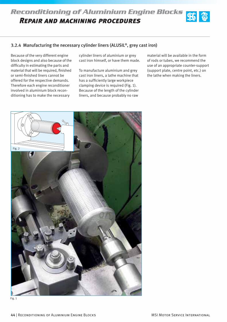
44 | Reconditioning of Aluminium Engine Blocks MSI Motor Service International
Reconditioning of Aluminium Engine BlocksRepair and machining procedures
Fig. 2
Fig. 1
Because of the very different engine block designs and also because of the diffi culty in estimating the parts and material that will be required, fi nished or semi-fi nished liners cannot be offered for the respective demands. Therefore each engine reconditioner involved in aluminium block recon-ditioning has to make the necessary
3.2.4 Manufacturing the necessary cylinder liners (ALUSIL®, grey cast iron)
cylinder liners of aluminium or grey cast iron himself, or have them made.
To manufacture aluminium and grey cast iron liners, a lathe machine that has a suffi ciently large workpiece clamping device is required (Fig. 1). Because of the length of the cylinder liners, and because probably no raw
material will be available in the form of rods or tubes, we recommend the use of an appropriate counter-support (support plate, centre point, etc.) on the lathe when making the liners.

MSI Motor Service International Reconditioning of Aluminium Engine Blocks | 45
Reconditioning of Aluminium Engine BlocksRepair and machining procedures
Fig. 4Fig. 3
Aluminium linersFor making aluminium liners, ALUSIL® cylinder sleeves are available in two different sizes (Figs. 3 and 4). The material composition of these slee-ves is identical to that of the original
ALUSIL® engine blocks. The mate-rial, however, is suitable not only for ALUSIL ® blocks, but also for repairing engine blocks that were produced using the LOKASIL® and Silitec®
Grey cast iron linersIn principle, any wet or dry cylinder liner that has the appropriate diameter and can be manipulated to suit the
Note
In the catalogue CD or the online shop of MSI Motor Service International GmbH (the Internet address is on the back cover of the brochure) the appropriate cylinder liners made of grey cast iron can be selected under the heading “search according to measurements”.
desired purpose can be used to make the necessary grey cast iron liners.
processes and for laser alloyed cylin-der sliding surfaces.
D d L n° KS
85 mm 74 mm 160 mm 89 571 190
105 mm 84 mm 160 mm 89 572 190

46 | Reconditioning of Aluminium Engine Blocks MSI Motor Service International
Reconditioning of Aluminium Engine BlocksRepair and machining procedures
Liner measurements, degree of contraction
The necessary repair liners can be made based on the following meas-urements. The measurements apply to ALUSIL® as well as to grey cast iron liners.
In calculating the exact geometry of the liners to be made, we recommend that the liner walls be kept as thick as possible before shrink-fi t. In other words, the liner walls will be reduced to the desired thickness of 1.5 to 3 mm by drilling and honing after shrinking and fi nishing. This way the liners will remain as round as possible before and during installation and will be able to be inserted well into the cylinder counterbore. Because of the increased thickness of the material, it will take more time for the tempera-tures to adjust and for the liner to be fi xed during the shrinking process. When the liner is being made, the measurement of the outside diameter will also be more exact than for a very thin liner, which can be deformed by a few 1/100 mm solely by the pressure of the measuring instrument.
Measurement of the cylinder liner Setpoints
Length of cylinder liner L = length of cylinder +0.2 mm
Outside diameter of cylinder liner Ød = A + X
Overlap (amount of contraction) X = 0.08–0.1 mm
Required thickness of liner wall after cylinder fi nishing
> = 1.5 mm
Maximum thickness of liner wall after cylinder fi nishing
3 mm
Surface roughness of outer diameter of the liner (ØD)
Rz 6.3 µm
Surface roughness of other machined areas
Rz 25 µm
Admissible ovality of liner 0.02 mm
Liner fl ange measurements Setpoints
Flange diameter ØD = Ød +2 mm
Flange height = C +0.2 mm
Cylinder counterbore measurements Setpoints
Diameter of cylinder counterbore A
Diameter of fl ange seat counterbore B = ØD +0.1 mm
Height of fl ange seat counterbore C = 4–5 mm

MSI Motor Service International Reconditioning of Aluminium Engine Blocks | 47
Reconditioning of Aluminium Engine BlocksRepair and machining procedures
Fig. 1
Tip
Because of the minimum difference between the dimensions of the liner and the engine block counterbore, it often happens that the cylinder counterbore is drilled a few 1/100 mm larger, which will cause a liner
that has already been made to have a diameter that is too small. For this reason we recommend that the liner counterbores fi rst be made in the engine block and measured using a bore gauge and only then that the
cylinder liners be machined to the pro-per overdimension. This will ensure that the necessary overlap (amount of contraction) is maintained.

48 | Reconditioning of Aluminium Engine Blocks MSI Motor Service International
Reconditioning of Aluminium Engine BlocksRepair and machining procedures
Fig. 1
Fig. 2
The main crankshaft bearing covers are installed with embedded bear-ing shells (used or new) and screwed down using the tightening torque specifi ed by the engine manufacturer. Then the engine block is placed on the drilling mill, roughly aligned and fastened. Next the alignment is fi ne-adjusted by placing compensating plates underneath or by swivelling the machining table until the engine block is brought into the fi nal machining position.
To ensure that the cylinder counter-bores are at an exact right angle to the crankshaft axis during machin-ing, we recommend that the block be aligned not only based on the end face of the engine block, but that the rectangularity also be checked by running the dial gauge vertically along the cylinder bores (lengthwise and across the crankshaft axis). The most precise procedure for aligning the engine block exactly on the fi nishing machine, however, is to measure the main crankshaft bearing gap and the alignment of the engine block in the X and Y axes with reference to the crankshaft axis. Any existing misalign-ments in the surface parallelism of the cylinder head sealing face and the rectangularity of the cylinder bores caused by earlier machining can be discovered or corrected this way. This procedure is especially recommended if the end face of the engine block has to be machined in two or more steps with respect to the cylinder blocks, as is the case with V and W shaped cylinder arrangements.
3.2.5 Preparing the cylinder liner counterbores in the engine block

MSI Motor Service International Reconditioning of Aluminium Engine Blocks | 49
Reconditioning of Aluminium Engine BlocksRepair and machining procedures
Fig. 3
Fig. 4
Fig. 5
Carbide or diamond tipped tools can be used to prepare the counterbores to support the liners. The higher the speed, the less material removed, and the sharper the tool, the better the surface quality of the counterbore will be. To obtain counterbores that are exactly round and have the precise measurements, the following steps are recommended for machining the cylinder counterbores:
Stage 1: Predrilling with a material removal of max. 0.5 mm per step
Stage 2: Finish drilling with a material removal of max. 0.1 mm
The following steps apply only to lin-ers with liner fl ange. See Section3.2.3, “Shaping the liner fi t in alumin-ium engine blocks”
Stage 3: Preparing and machining the fl ange seat counterbore to the desired “C” depth
Stage 4: Chamfering the upper edge of the cylinder counterbore to avoid fi tting problems caused by lack of precision between the shape of the liner fl ange and the upper edge of the cylinder counterbore. (Recommended dimen-sions: 0.5 mm x 45° (see Figure 2))
Rebushing of adjacent cylinder boresEvery engine block is different. It cannot always be predicted how the material will behave during recon-ditioning. For engine blocks with cylinder tubes that are cast together and have a narrow wall (Fig. 3) it might be recommendable fi rst to prepare one cylinder counterbore, and then to shrink the liner. The adjacent cylinder counterbore would then be drilled and rebushed in a completely separate step. This would minimise or rule out deformations in the cylinder coun-terbore of the adjacent cylinder that could be caused by the contraction of the fi rst liner.
In engine blocks with standalone cylinder tubes that were not cast together (Fig. 4) there are no problems of this nature due to the absence of a mechanical bond with the neighbour-ing cylinders. Here the cylinder coun-terbores can be drilled in immediate succession.
Cylinder counterbore measurements Setpoints
Diameter of cylinder counterbore A
Diameter of fl ange seat counterbore B = ØD +0.1 mm
Height of fl ange seat counterbore C = 4–5 mm

50 | Reconditioning of Aluminium Engine Blocks MSI Motor Service International
Reconditioning of Aluminium Engine BlocksRepair and machining procedures
Fig. 1
Fig. 2
Shrinking cylinder liners with dry iceDry ice can be used to cool cylinder liners down to about –80° C. A rela-tively simple way to make dry ice is to use the CO2 (carbon dioxide) in the compressed bottle of the rising tube. Regarding the physical principle: Dry ice is produced by the sudden rapid expansion of the gas when it fl ows out. The dry ice can be collected in an insulated container. This insulated container should meet the necessary insulation and strength requirements. Figure 1 shows a leather bag used for this purpose. The liners are placed in an appropriate container (a cardboard box is suffi cient) and surrounded with dry ice to cool down.
Shrinking the cylinder liners with liquid nitrogenThe cylinder liner is placed in liquid nitrogen (Fig. 2) which causes it to reach a temperature of –180° to
–200° Celsius. Liquid nitrogen can be obtained from the local gas dealer.
3.2.6 Shrinking of cylinder liners
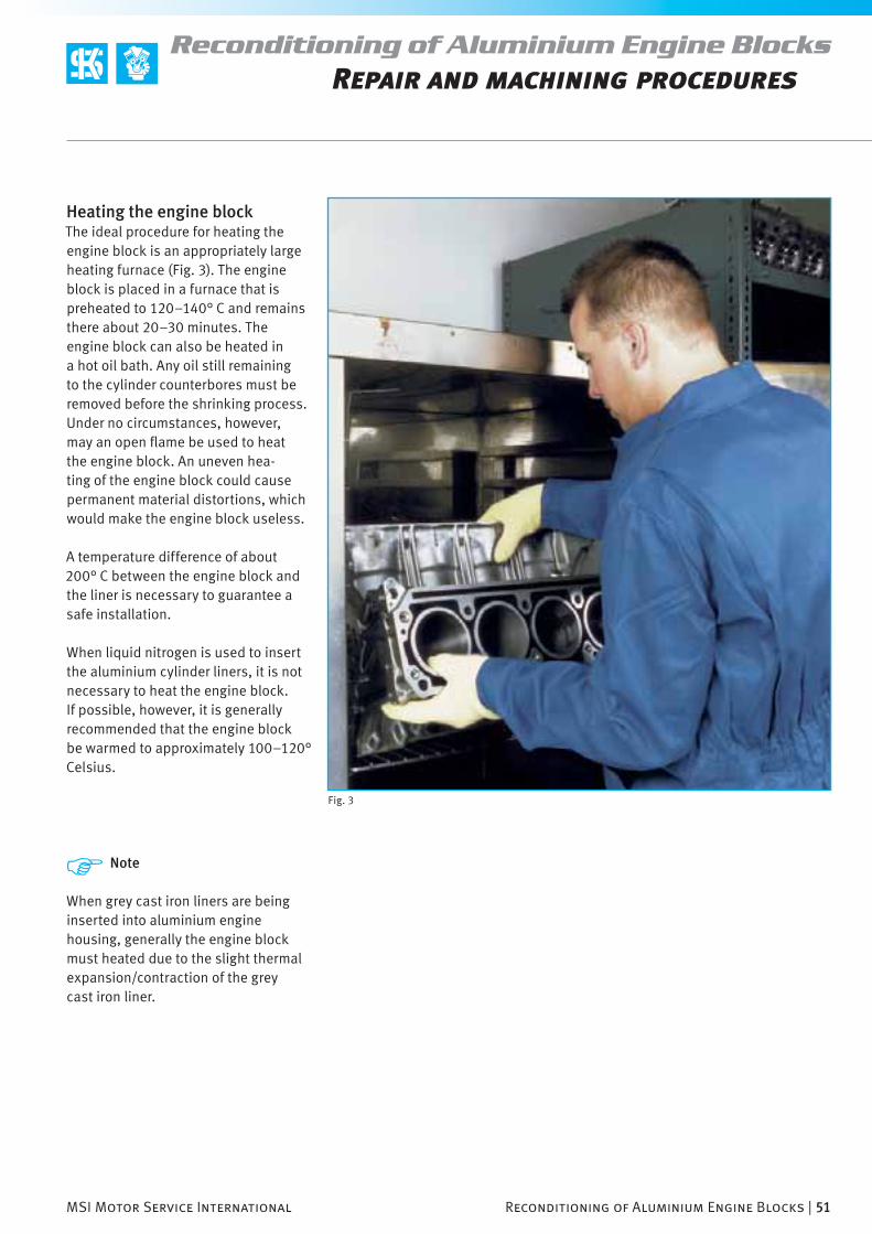
MSI Motor Service International Reconditioning of Aluminium Engine Blocks | 51
Reconditioning of Aluminium Engine BlocksRepair and machining procedures
Fig. 3
Heating the engine blockThe ideal procedure for heating the engine block is an appropriately large heating furnace (Fig. 3). The engine block is placed in a furnace that is preheated to 120–140° C and remains there about 20–30 minutes. The engine block can also be heated in a hot oil bath. Any oil still remaining to the cylinder counterbores must be removed before the shrinking process. Under no circumstances, however, may an open fl ame be used to heat the engine block. An uneven hea-ting of the engine block could cause permanent material distortions, which would make the engine block useless.
A temperature difference of about 200° C between the engine block and the liner is necessary to guarantee a safe installation.
When liquid nitrogen is used to insert the aluminium cylinder liners, it is not necessary to heat the engine block. If possible, however, it is generally recommended that the engine block be warmed to approximately 100–120° Celsius.
Note
When grey cast iron liners are being inserted into aluminium engine housing, generally the engine block must heated due to the slight thermal expansion/contraction of the grey cast iron liner.

52 | Reconditioning of Aluminium Engine Blocks MSI Motor Service International
Reconditioning of Aluminium Engine BlocksRepair and machining procedures
Fig. 1
Fig. 2
Smoothing the surface of the engine blockAfter the liner(s) have been inserted and the engine block has been alig-ned, the surface of the engine block has to be smoothed (Fig. 2). 0.1 mm of the material should be removed to ensure a completely fl at surface.
Inserting the cylinder liner The insertion of the cylinder liner (Fig. 1) is not a problem at all. The cooling down of the cylinder liner reduces the diameter by about 0.15 mm, while the heating of the engine block enlarges the cylinder coun-terbore by about 0.10 mm, so that when the liner is inserted, there will be a clearance of –0.15 to 0.20 mm less the desired overlap. The cylinder liners, however, must be inserted rela-tively quickly and in one step. During insertion, the liner must literally drop into the cylinder counterbore. It can, however, spring back a bit when being placed in the engine block. For this reason, the liner must be held down briefl y by a piece of wood or plastic so that it will not be fi xed in a sprung back state. The liner will be fi xed as soon as the temperature between the cylinder liner and the counterbore is balanced. If the cylinder liner becomes fi xed in the wrong position, the shrink-ing process will have been unsuccess-ful and must be repeated. Reinsertion, even with the assistance of a press, is not possible. The damaged cylinder liner must be drilled out by the drilling machine and removed. In this case the liner will have to be drilled until the thickness of the remaining wall is 0.3–0.5 mm and then the remaining part will have to be removed with a screwdriver.
Important!
For the best possible sealing effect of the cylinder head sealing, the roughness of the fl at surface should correspond to the value prescribed by the engine manufacturer.

MSI Motor Service International Reconditioning of Aluminium Engine Blocks | 53
Reconditioning of Aluminium Engine BlocksRepair and machining procedures
Fig. 3
3.3.1 Machines and tools required
Aluminium blocks are machined differently from grey cast iron engine blocks. The following machining processes are associated closely with the aluminium cylinder machining processes used in series production with respect to process reliability. The following machining steps and parameters described are specially oriented to the KS machining tools mentioned in Section 3.8, “KS tools for machining aluminium cylinder
3.3 Machining aluminium cylinder sliding surfaces (The KS aluminium honing process)
bores”. Any deviation or change from these norms will have an impact on the surface quality.
Every engine reconditioner can use the following information to check and decide for himself whether the alu-minium cylinder sliding surfaces can be machined using the machines and tools available to him. Under certain circumstances, changes will have to be made to existing machines in order
to realise the necessary machining parameters. The machining processes described in the following sections provide precise information on the requirements for machines, tools and cutting material.

54 | Reconditioning of Aluminium Engine Blocks MSI Motor Service International
Reconditioning of Aluminium Engine BlocksRepair and machining procedures
Fig. 1
3.3.2 Overview of the individual machining steps
The hardness of the bond in metal-lically bonded diamond honing stones has a strong infl uence on the wear characteristics and thus on the self-sharpening effect of the stones. This means that such tools must be checked from time to time and sharp-ened if necessary in order to maintain the cutting capacity. If a necessary sharpening of dull honing stones is not performed, you will still have good cutting capacity. But the loss of silicon crystals on the cylinder surface that this will cause can no longer be compensated by subsequent honing. For this reason we recommend only the use of synthetic resin-bonded KS diamond honing stones for the fi nal honing. The material removal capac-ity and self-sharpening process of the stones is good, the machining results are optimal, and the somewhat increased time required for machining is of little importance.
Figure 1 shows the individual ma-chining steps in diagram form. In the machining of aluminium silicon surfaces is must be emphasised that each of the machining steps described is important for the fi nal result. An error made during drilling (e.g. the use of incorrect or dull tools, or failure to stay within the machining parameters) cannot be corrected in the subsequent machining steps. The same applies for the following honing process. Only compliance with the given machining parameters will ensure that the silicon crystals – which represent the hard and wear-resistant reinforcement of the cylinder surface – will be cut with precision and not be torn out.
In series production the actual honing process is divided into two steps, pre and fi nal honing. Prehoning occurs in series production by using honing stones made of metallically bonded diamonds, and can be omitted in the reconditioning of aluminium engine blocks. The prehoning step is per-formed in series production for the sake of shorter machining time and longer tool life. This step is not advan-tageous for the engine reconditioner. The reason is the higher cost of tools and machining.
1. After drilling
2. After honing
3. After the silicon exposure

MSI Motor Service International Reconditioning of Aluminium Engine Blocks | 55
Reconditioning of Aluminium Engine BlocksRepair and machining procedures
Fig. 2 – WALTER AG
Fig. 3 – WALTER AG
3.4.1 Drilling tools and cutting material
In the manufacturing of engine blocks, multiple blade cutters are employed to drill the cylinder bores (Fig. 3). But for engine reconditioning, the usual single-blade cutters are suitable. The prerequisite for this is the correct cut-ting material.
To keep the rate of destruction of the silicon crystals in the cylinder wall to a minimum, the fi ne drilling of the cylinder bores must be done with PCD cutters. PCD is the abbreviation for polycrystalline diamonds. These are synthetically produced diamonds that are fi nely distributed by a sinter-ing process and embedded in a metal matrix.
When PCD‘s are used for cutting, the diamond layer is applied to a hard metal base. A polycrystalline diamond is up to 500 times more wear-resistant than hard metal.The hardness of the PCD layer is almost that of a monocrystalline dia-mond. It has an excellent mechanical wear resistance, extreme toughness and high thermal conductivity. Only when faultless PCD cutters are used is it possible to ensure that silicon crystals embedded in the aluminium matrix will be cut precisely and clean-ly, and will not be torn out. Therefore, a constant surface quality inside a cylinder bore can only be produced by using diamond cutters.
3.4 Finish-drilling the cylinders
Note
Hard metal cutters must not be used to drill cylinder bores. Hard metal cutters would wear (become dull) on the very hard silicon crystals within a short time. This would increase the cutting pressure dramatically, and thus the degree of destruction of the crystals in the aluminium matrix. The increased cutting pressure will not only destroy the crystals on the surface, but will also damage the underlying crystals (depth damage). In the subsequent honing process these broken crystals will be cut. They won‘t break off immediately during honing, but it will be only a matter of time until they are loosened by the piston rings, break off during engine operation, and
cause abrasive wear on the pistons and cylinder surface. You can picture this like a fractured pane of glass with a lot of cracks. It still remains in the frame, but will not be able to with-stand subsequent pressure, and will ultimately fall out.
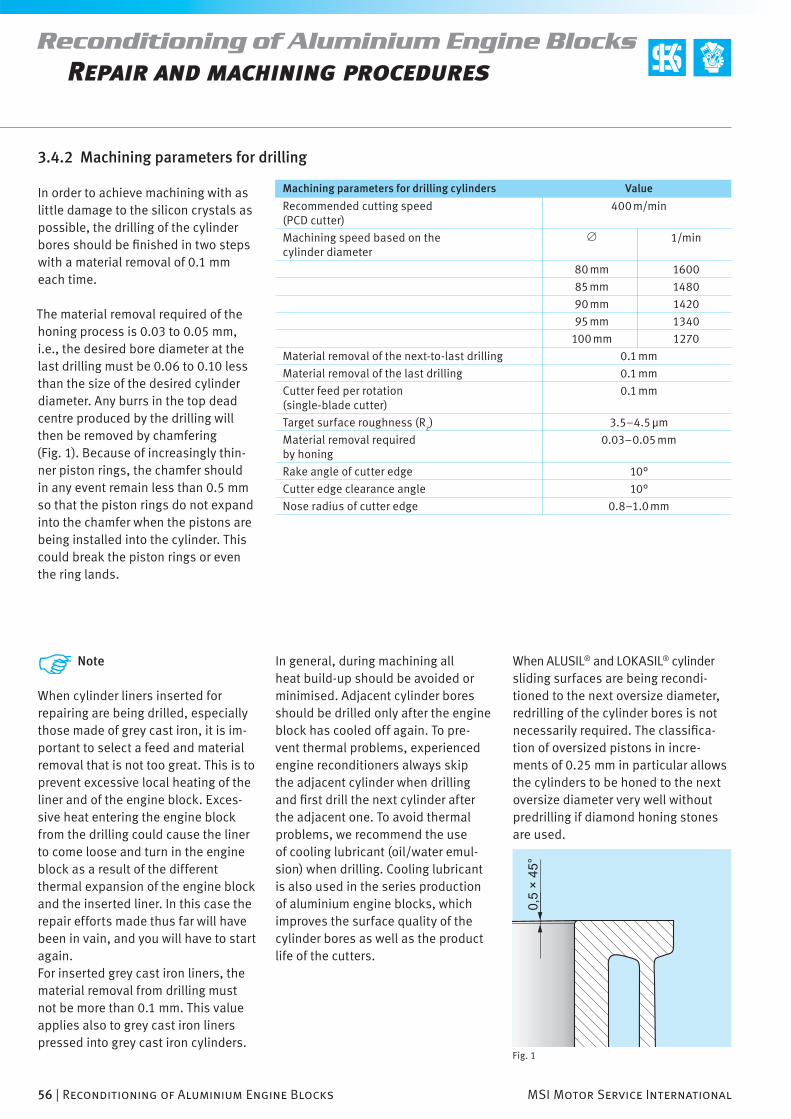
56 | Reconditioning of Aluminium Engine Blocks MSI Motor Service International
Reconditioning of Aluminium Engine BlocksRepair and machining procedures
Fig. 1
3.4.2 Machining parameters for drilling
In order to achieve machining with as little damage to the silicon crystals as possible, the drilling of the cylinder bores should be fi nished in two steps with a material removal of 0.1 mm each time.
The material removal required of the honing process is 0.03 to 0.05 mm, i.e., the desired bore diameter at the last drilling must be 0.06 to 0.10 less than the size of the desired cylinder diameter. Any burrs in the top dead centre produced by the drilling will then be removed by chamfering (Fig. 1). Because of increasingly thin-ner piston rings, the chamfer should in any event remain less than 0.5 mm so that the piston rings do not expand into the chamfer when the pistons are being installed into the cylinder. This could break the piston rings or even the ring lands.
Note
When cylinder liners inserted for repairing are being drilled, especially those made of grey cast iron, it is im-portant to select a feed and material removal that is not too great. This is to prevent excessive local heating of the liner and of the engine block. Exces-sive heat entering the engine block from the drilling could cause the liner to come loose and turn in the engine block as a result of the different thermal expansion of the engine block and the inserted liner. In this case the repair efforts made thus far will have been in vain, and you will have to start again.For inserted grey cast iron liners, the material removal from drilling must not be more than 0.1 mm. This value applies also to grey cast iron liners pressed into grey cast iron cylinders.
In general, during machining all heat build-up should be avoided or minimised. Adjacent cylinder bores should be drilled only after the engine block has cooled off again. To pre-vent thermal problems, experienced engine reconditioners always skip the adjacent cylinder when drilling and fi rst drill the next cylinder after the adjacent one. To avoid thermal problems, we recommend the use of cooling lubricant (oil/water emul-sion) when drilling. Cooling lubricant is also used in the series production of aluminium engine blocks, which improves the surface quality of the cylinder bores as well as the product life of the cutters.
Machining parameters for drilling cylinders Value
Recommended cutting speed (PCD cutter)
400 m/min
Machining speed based on the cylinder diameter
Ø 1/min
80 mm 1600
85 mm 1480
90 mm 1420
95 mm 1340
100 mm 1270
Material removal of the next-to-last drilling 0.1 mm
Material removal of the last drilling 0.1 mm
Cutter feed per rotation (single-blade cutter)
0.1 mm
Target surface roughness (Rz) 3.5–4.5 µm
Material removal required by honing
0.03–0.05 mm
Rake angle of cutter edge 10°
Cutter edge clearance angle 10°
Nose radius of cutter edge 0.8–1.0 mm
When ALUSIL® and LOKASIL® cylinder sliding surfaces are being recondi-tioned to the next oversize diameter, redrilling of the cylinder bores is not necessarily required. The classifi ca-tion of oversized pistons in incre-ments of 0.25 mm in particular allows the cylinders to be honed to the next oversize diameter very well without predrilling if diamond honing stones are used.
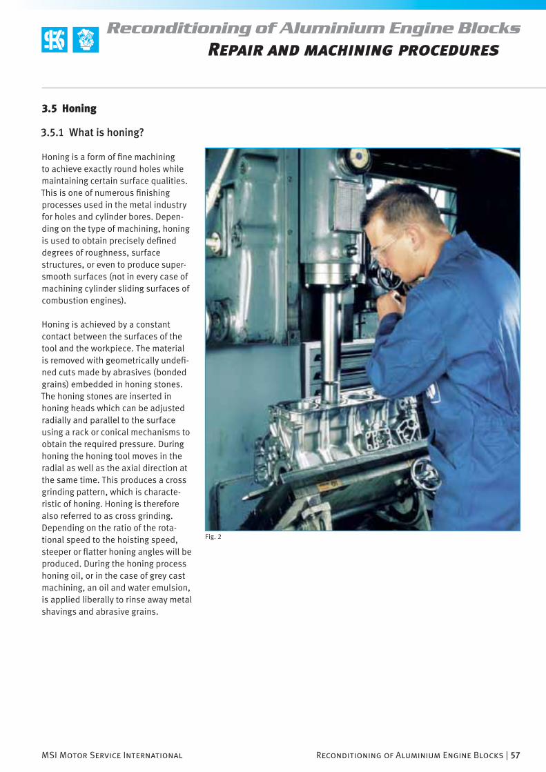
MSI Motor Service International Reconditioning of Aluminium Engine Blocks | 57
Reconditioning of Aluminium Engine BlocksRepair and machining procedures
Fig. 2
3.5.1 What is honing?
Honing is a form of fi ne machining to achieve exactly round holes while maintaining certain surface qualities. This is one of numerous fi nishing processes used in the metal industry for holes and cylinder bores. Depen-ding on the type of machining, honing is used to obtain precisely defi ned degrees of roughness, surface structures, or even to produce super-smooth surfaces (not in every case of machining cylinder sliding surfaces of combustion engines).
Honing is achieved by a constant contact between the surfaces of the tool and the workpiece. The material is removed with geometrically undefi -ned cuts made by abrasives (bonded grains) embedded in honing stones. The honing stones are inserted in honing heads which can be adjusted radially and parallel to the surface using a rack or conical mechanisms to obtain the required pressure. During honing the honing tool moves in the radial as well as the axial direction at the same time. This produces a cross grinding pattern, which is characte-ristic of honing. Honing is therefore also referred to as cross grinding. Depending on the ratio of the rota-tional speed to the hoisting speed, steeper or fl atter honing angles will be produced. During the honing process honing oil, or in the case of grey cast machining, an oil and water emulsion, is applied liberally to rinse away metal shavings and abrasive grains.
3.5 Honing

58 | Reconditioning of Aluminium Engine Blocks MSI Motor Service International
Reconditioning of Aluminium Engine BlocksRepair and machining procedures
3.5.2 The purpose of honing
Finishing by honing not only produces holes or cylinder bores with the desired diameter and surface quality. It can also correct errors in the geom-etry of the bore arising from previous machining steps, or errors that could not be corrected previously. Below is a list of the most frequent shape and surface errors.
Cone shape Trumpet shape
Barrel shape Waviness
curved bore
drilling grooves
inclined bore
Ovality Undersize
3.5.3 Comparing the honing of grey cast iron to the honing of aluminium
The roughness of aluminium silicon sliding surfaces does not depend on the size of the grain of the abrasive used and on the depth that can be achieved by the honing pattern (cross grinding), as is the case in the honing of grey cast iron. Moreover, the rough-ness profi le is determined by the size of the grain of the primary silicon crystals present in the ALUSIL® and the depth of its exposure.
The differences between a honed grey cast iron cylinder surface and an ALUSIL® surface are explained below. Figure 1 shows a plateau-honed grey cast surface and a roughness graph, while Figure 2 shows an ALUSIL® cylin-der surface with a roughness graph.
The surface structure that is character-istic of the grey cast iron cylinder slid-ing surface (cross grinding) has ridges (valleys) for oil retention and plateaus that are created in different machin-ing steps by honing. The plateaus that represent the sliding surface for the piston rings are produced in a fi nal step by cutting off the profi le peaks. Therefore, the pressure applied by the

MSI Motor Service International Reconditioning of Aluminium Engine Blocks | 59
Reconditioning of Aluminium Engine BlocksRepair and machining procedures
honing stone, the honing angle, the size of the grain and the honing speed are important parameters for obtain-ing the right surface topography.
Note
Because of the complexity of the subject, the honing of grey cast iron cylinder bores is not within the scope of this brochure. Therefore we recom-mend that you study our brochure entitled “Honing grey cast iron engine blocks”. Ordering information is given in the attachment to this brochure.
In the case of ALUSIL® cylinder sliding surfaces, the shape and size of the silicon crystals embedded in the aluminium produce the plateaus on which the pistons and piston rings run. The distance between the silicon crystals determines the width and the shape of the profi le valleys, while the depth of the exposure corresponds to the depth of the profi le valley.
Important!
To obtain best machining results from honing ALUSIL® attention must be paid to the silicon, that the crystals are cut properly and are not torn out from the surface. This is achieved only by the appropriate honing stones and the correct machining parameters.
In the subsequent exposure of the silicon crystals, it is mainly the depth of the exposure that is of signifi cance. In the mechanical exposure process, the silicon grains are still somewhat rounded, which has a positive impact on the sliding behaviour of the piston rings. In the case of etching, the sharp edges of the silicon crystals that are produced by cutting are not rounded, which produces a somewhat greater wear on the piston rings during the engine break-in.
Fig. 1
Fig. 2
Rpk
0.31 µmR
k 1.82 µm
Rvk
2.25 µmR
a 0.71 µm
Rz 7.02 µm
Mr2
75 %
Rpk
0.39 µmR
k 0.55 µm
Rvk
0.16 µmR
a 0.21 µm
Rz 1.35 µm
Mr2
92 %

60 | Reconditioning of Aluminium Engine Blocks MSI Motor Service International
Reconditioning of Aluminium Engine BlocksRepair and machining procedures
Fig. 1 Fig. 2
Fig. 3
3.5.4 Requirements of the honing tool and of the honing stones
Honing toolsWhen aluminium is being machined, the honing and the exposure process-es must be carried out together using multiple-stone honing tools. To obtain an exact bore geometry, 5 to 8 honing stones must be distributed around the circumference (Fig. 1).In the case of multiple-stone honing heads, the cutting stones are adjusted hydraulically or electromechanically by a central cone spreading device (Fig. 3). The more suitable machines are those that adjust the honing stones hydraulically because the pres-sure and thus the degree of contact can be adjusted very fi nely.
Manual, mechanical stone adjusting devices, as in the case of the gear rack device (Fig. 2) cannot be adjusted with the necessary precision. Espe-cially the low cutting pressures that must be maintained when machining aluminium can hardly be applied and adjusted manually.Therefore, standard honing tools with 2 or 4 honing stones that are manipu-lated manually by gear racks are not suitable for machining aluminium. They cannot achieve the desired surface quality and bore geometry. Furthermore, guide shoes may not be used for honing aluminium.
1. Cardan joint
2. Honing tool
3. Annular spring
4. Honing stone
5. Honing stone support
6. Feed cone

MSI Motor Service International Reconditioning of Aluminium Engine Blocks | 61
Reconditioning of Aluminium Engine BlocksRepair and machining procedures
Fig. 4
Honing stonesBecause of special requirements, only abrasives with plastic bonded diamonds may be used when hon-ing aluminium cylinder sliding sur-faces. The hardness of the diamonds ensures a precise cutting of the hard phases of the silicon embedded in the aluminium. The plastic bond of the diamond cutting stones prevents the problems that are known to occur with ceramic cutting stones in the honing of aluminium.
The stones are also self-sharpening with soft material like aluminium, i.e., the bonding of the diamonds is suf-fi ciently fi xed to hold the diamonds during honing, and on the other hand, soft enough the allow diamond grains that have become dull to break off.Keeping to the machining parameters prevents the embedded silicon crys-tals from being destroyed or broken off and prepares the surface in the
best way for the subsequent exposure process. The KS diamond cutting stones (see Section 3.8, “KS tools for machining aluminium cylinder bores”) were developed and adapted specially for machining ALUSIL®, LOKASIL® and comparable aluminium silicon materials.
Note
Ceramic honing stones such as those that have been used and even recommend for engine reconditioning do not have the machining properties and the necessary process reliability required today. Vitrifi ed abrasives of silicon carbide or corundum are hardly suitable for the precise and proper cutting of silicon crystals. Because of the hardness of the silicon crys-tals, the wear resistance of ceramic abrasives is inadequate to ensure the necessary tool life with clean machi-ning results.
The bonding of the abrasive grains in ceramic honing stones is too hard for
machining aluminium cylinder sliding surfaces. The self-sharpening effect of ceramic honing stones, such as the tearing off or splintering of cutting grains that become dull in the honing of grey cast iron, does not occur when aluminium is being honed. The dull cutting grains remain in the stone, which increases the cutting pressure. The silicon crystals embedded in the cylinder wall, which are indispensable components associated with the run-ning of the piston rings, cannot with-stand excessive cutting pressure and are torn and destroyed. Furthermore, if the honing stones are contamina-ted (oversmeared) with aluminium,
the cylinder surfaces that have been machined, and are almost ready, are often ruined. In this case, the alumini-um rubbed onto the honing stones will create spiral shaped scratches on the sliding surface within a few rotations, which will render the entire honing useless.

62 | Reconditioning of Aluminium Engine Blocks MSI Motor Service International
Reconditioning of Aluminium Engine BlocksRepair and machining procedures
Fig. 2
3.5.5 Cooling lubricant for honing and mechanical exposure process
Common commercial honing oil can be used as a cooling lubricant for honing KS aluminium and also for mechani-cal exposuring process. The viscosity should be in the low or medium range. High viscose (viscid) honing oil and
Important!
The quality and characteristics of the cooling lubricant have a considerable infl uence on the honing quality. Care must therefore always be taken to ensure that the oil and the oil fi lter are changed in regular intervals.
3.5.6 Machining parameters for honing
The “KS aluminium honing” is carried out at higher rotational speeds and at a slower hoisting speed compared to the the honing of grey cast iron. This produces very fl at honing angles. This has proven to be advantageous in keeping the degree of silicon destruc-tion as low as possible. Also the cutting pressure present in the honing stones is much lower than is the case with the honing of grey cast iron. The aluminium to be removed is very soft and can be machined quite easily with the KS diamond honing stones. Because of the reduced hardness of the aluminium silicon alloy, the pres-sure on the cylinder wall must not be too great. The cylinder wall would be
deformed under high pressure, which would deteriorate the bore geometry (please refer to Section 3.7.2, “Errors in cylinder bore geometry due to wrong machining”). For this reason the width of the diamond honing stones offered by KS is only about half that of standard honing stones, such as those made of ceramic. At the same specifi c pressure applied by the hon-ing stones, the pressing force can be reduced by a half with half the width of the honing stones (Fig. 2). This will effectively prevent or minimise defor-mations of the cylinder wall caused by excessive pressure.
Honing with KS diamond honing stones bonded with synthetic resin should take at least 90 seconds per cylinder bore. Shorter machining times indicate excessive pressure applied to the honing stones and will result in increased wear on the stones.
oil/water emulsions must not be used with the honing stones offered here.

MSI Motor Service International Reconditioning of Aluminium Engine Blocks | 63
Reconditioning of Aluminium Engine BlocksRepair and machining procedures
Note
Honing causes the cylinder bores to heat up. Because of the thermal expansion of the engine block asso-ciated with this process, the cylinder diameter should be tested (measured) only after it has cooled off to room temperature.
Important!
To prevent the stones from being clogged with rubbed-on aluminium particles, and to improve lubrication, honing should be interrupted briefl y after each 30 seconds. Contact of the stones with the cylinder wall should be interrupted. The work should be continued only after the cutting sur-face has been wetted and rinsed with honing oil. In order for the stones to wear evenly, in series production the rotational direction of the honing tool is reversed each time a new cylinder bore is machined.
Machining parameters for honing Value
Recommended rotational speed for honing 250–350 1/min
Minimum rotational speed for honing 200 1/min
Maximum rotational speed for honing 400 1/min
Hoisting speed of the honing head based on the Rotational speed
1/min m/min
400 16
350 14
300 12
200 8
Honing angle (product of rotation speed and hoisting speed) 15–20°
Required material removal based on the diameter of the cylinder
0.06–0.1 mm
Recommended pressure applied by honing stone 30 N/cm²
Maximum pressure applied by honing stone 40 N/cm²
Total machining time per cylinder bore (guideline) > = 90 s
Target surface roughness (Ra) 0.06–0.10 µm
Honing stone overrun in TDC and BDC based on the length of the honing stone
W 30 %
Target degree of destruction of silicon crystals 5–10 %
Maximum admissible degree of destruction of silicon crystals max. 30 %
Admissible ovality of cylinder bores (production tolerance)
+/–6 µm

64 | Reconditioning of Aluminium Engine Blocks MSI Motor Service International
Reconditioning of Aluminium Engine BlocksRepair and machining procedures
Fig. 1
Fig. 2
Fig. 3
3.6.1 What is the exposure process?
An exposure is a recess in the alumi-nium matrix surrounding the silicon crystals. The exposure process is necessary because aluminium, as an essential sliding element for piston rings, is too soft and therefore not suffi ciently durable. For this reason, the silicon crystals are “exposed”
3.6 Exposing the silicon crystals
from the surrounding aluminium to up a certain depth in the last work step. This allows the piston and the rings to run over a very hard, and thus very durable surface reinforced with silicon crystals. Depending on the require-ments of the engine and the exposure process used, the depth of the expos-
ure (Rpk
) is between 0.3 and 0.7 µm. The minimum exposure depth of R
pk,
however, should not fall below 0.3 µm.
Exposure by etchingIn the etching exposure process, the aluminium surrounding the silicon crystals is etched away with a 10–20% caustic soda at 60°C. The duration of the etching process is determined by the depth of the ex-posure. The etching produces a very deep exposure in a process that is gentle on the silicon crystals. Unlike the mechanical or lapping exposing, the edges of the silicon crystals are not rounded off. Their edges remain as sharp as they were cut in the hon-ing process (Fig. 1). The sharp edges cause the piston rings to wear a bit more when the engine is being run in. Etching is no longer used in the series production of engine blocks manufac-tured using the ALUSIL® and LOKASIL® processes. The actual etching process is not a problem, but the equipment and effort required for handling and cleaning baths is too great and thus too expensive.
For engine blocks that are manufac-tured using the Silitec® process, the gentler etching process continues to be used at the present because of the very small silicon crystals (2–4 µm). The mechanical exposure process has not been able to be applied in this process because of insuffi cient proc-ess reliability.
Figures 2 and 3 show the surface of an etched exposure of a cylinder bore of an aluminium engine block manu-factured using the LOKASIL® process enlarged approximately 150 and 300 times respectively.
3.6.2 Different silicon exposure processes

MSI Motor Service International Reconditioning of Aluminium Engine Blocks | 65
Reconditioning of Aluminium Engine BlocksRepair and machining procedures
Fig. 4
Fig. 5
Exposure with lapping paste (Current exposure process for ALUSIL® and LOKASIL® cylinder sliding surfaces)
This process is used exclusively for reconditioning aluminium engine blocks. In this type of exposure, the surrounding aluminium is removed by an abrasive paste with silicon parti-cles. Neither a mandrel nor a lapping sleeve is used in this case, but rather felt strips are used to apply the lap-ping paste (Fig. 5).
Here the loose cutting grains are responsible for the exposure process. The exposure process is very easy from the handling aspect and can be executed with minimum effort. The subsequent cleaning of the engine block with lapping paste, however, is more complicated than is the case with a mechanical exposure process. For this reason, the lapping exposure process is not used in series produc-tion. Because of the size of the silicon grains in the paste and the packing density of the silicon crystals on the surface of the cylinder bore, the paste must be adapted to the respective application. To obtain certain expo-sure depths the abrasive grains of the lapping paste must be smaller than the space between the silicon crystals of the cylinder surface. The lapping paste offered in Section 3.8,
“Tools” is suited for machining Silitec® cylinder sliding surfaces as well as for cylinder sliding surfaces manufac-tured using the ALUSIL® and LOKASIL® processes. Although the lapping exposure process is applicable to all 3 variants mentioned, for ALUSIL® and LOKASIL® cylinder sliding surfaces, however, the mechanical exposure process is preferable.

66 | Reconditioning of Aluminium Engine Blocks MSI Motor Service International
Reconditioning of Aluminium Engine BlocksRepair and machining procedures
Machining parameters for the lapping exposure processInexpensive tools can be used for the lapping exposure process. Standard honing heads with adjustable gear racks and felt strips can be used. To obtain the same results for all the cylinder bores, unused lapping paste should always be applied to each additional cylinder sliding surface to be machined. Because abrasive grains must roll off onto the surface, the pressure applied must be very low. The low pressure allows the grains to
lodge between the felt strip and the cylinder wall to accomplish the expo-sure process. If too much pressure is applied, the lapping paste will rather be pressed away from the cylinder wall and removed.
Guide shoes, which are necessary for honing steel and grey cast iron in order to obtain perfect bore geometry, should not be used in the lapping exposure process. This could dete-
riorate the surface quality and could destroy the silicon crystals. Besides, the bore geometry cannot be changed in the lapping exposure process. The material removal is just in the range of micro millimetres.
Machining parameters for the lapping exposure process Parameters
Recommended rotational speed for the exposure process 180–230 1/min
Recommend duration of exposure process approx. 60 s
Stone overrun based on the length of the stone max. 15 %
Possible change in diameter of cylinder as a result of lapping exposing ≈ 1 µm
Maximum recommended pressure applied by honing stone 20 N/cm²
Recommended depth of exposure (Rpk
) 0.4–0.7 µm
Minimum depth of exposure (Rpk
) 0.3 µm
Attention!
Any remaining lapping paste that is not removed after the engine block has been machined can produce wear in an engine. The fi ne, sharp silicon grains in the paste are like sand in their effect and cause considerable abrasion. To ensure that all loose particles are removed from the cylinder surfaces when the engine is being cleaned, we recommend that the cylinder bores be wiped off with a micro fi bre or similar cloth soaked in petrol after the actual washing process.

MSI Motor Service International Reconditioning of Aluminium Engine Blocks | 67
Reconditioning of Aluminium Engine BlocksRepair and machining procedures
Fig. 1
Fig. 2
Mechanically produced exposure (New KS exposure process for ALUSIL® and LOKASIL® cylinder sliding surfaces)In the case of a mechanically produced exposure, the aluminium is removed by highly porous exposing stones specially developed by KS. The porous, synthetic resin based material contains ceramic abrasive grains made of pure corundum. Because of the porous structure and elasticity of the bonding, the exposing stones are very soft and yielding. Because they are yielding, the stones possess a property that yields to the silicon crystal protruding from the cylinder wall, while the softer alu-minium between the silicon crystals is removed. In the mechanical exposure process the sharp edges of the silicon crystals are also rounded off (Figs. 1
and 2), which results in less wear on the piston rings.This exposure process, patented by KS Aluminium Technologie AG, has become the standard exposure proc-ess for ALUSIL® and LOKASIL® cylinder sliding surfaces in series production. In addition to shorter cycle times, the mechanical exposure process allows the use of normal honing oil, and is a seamless addition to the preceding machining steps. This process can achieve medium exposure depths. The deeper the exposure to be produced, the higher the pressure applied by the exposing stones must be. Higher pres-sure applied, however, reduces the product life of the exposing stones.
Machining parameters for the mechanical exposure process Value
Recommended rotational speed for the exposure process approx. 200 1/min
Hoisting speed approx. 8 m/min
Stone overrun based on the length of the stone max. 15 %
Exposure angle (honing angle) 15–20°
Change in diameter of cylinder caused by the mechanical exposure ≈ 1–3 µm
Recommended pressure applied by honing stone 30 N/cm²
Recommended depth of exposure (Rpk
) > = 0.4 µm
Minimum depth of exposure (Rpk
) 0.3 µm
Recommend duration of exposure process 2 x 30s ***
Cooling lubricant (do not use oil/water emulsion) Honing oil
*** To expose the silicon crystals on all sides, in the mechanical exposure process the rotational direction of the tool must be changed every 30 seconds.
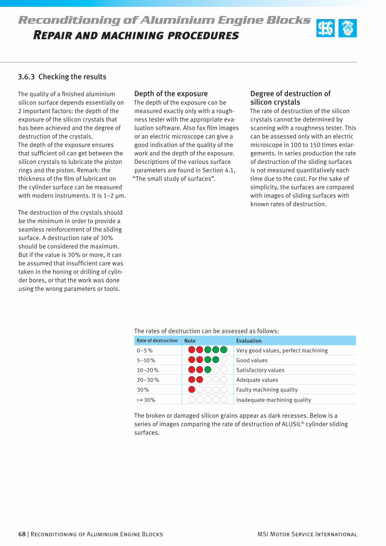
68 | Reconditioning of Aluminium Engine Blocks MSI Motor Service International
Reconditioning of Aluminium Engine BlocksRepair and machining procedures
The quality of a fi nished aluminium silicon surface depends essentially on 2 important factors: the depth of the exposure of the silicon crystals that has been achieved and the degree of destruction of the crystals.The depth of the exposure ensures that suffi cient oil can get between the silicon crystals to lubricate the piston rings and the piston. Remark: the thickness of the fi lm of lubricant on the cylinder surface can be measured with modern instruments. It is 1–2 µm.
The destruction of the crystals should be the minimum in order to provide a seamless reinforcement of the sliding surface. A destruction rate of 30% should be considered the maximum. But if the value is 30% or more, it can be assumed that insuffi cient care was taken in the honing or drilling of cylin-der bores, or that the work was done using the wrong parameters or tools.
3.6.3 Checking the results
Depth of the exposureThe depth of the exposure can be measured exactly only with a rough-ness tester with the appropriate eva-luation software. Also fax fi lm images or an electric microscope can give a good indication of the quality of the work and the depth of the exposure. Descriptions of the various surface parameters are found in Section 4.1,
“The small study of surfaces”.
Degree of destruction of silicon crystalsThe rate of destruction of the silicon crystals cannot be determined by scanning with a roughness tester. This can be assessed only with an electric microscope in 100 to 150 times enlar-gements. In series production the rate of destruction of the sliding surfaces is not measured quantitatively each time due to the cost. For the sake of simplicity, the surfaces are compared with images of sliding surfaces with known rates of destruction.
The rates of destruction can be assessed as follows:Rate of destruction Note Evaluation
0–5 % Very good values, perfect machining
5–10 % Good values
10–20 % Satisfactory values
20–30 % Adequate values
30 % Faulty machining quality
> = 30% Inadequate machining quality
The broken or damaged silicon grains appear as dark recesses. Below is a series of images comparing the rate of destruction of ALUSIL® cylinder sliding surfaces.
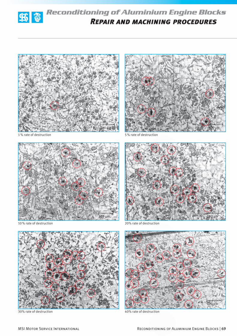
100 µm100 µm
100 µm100 µm
100 µm100 µm
MSI Motor Service International Reconditioning of Aluminium Engine Blocks | 69
Reconditioning of Aluminium Engine BlocksRepair and machining procedures
1 % rate of destruction 5 % rate of destruction
10 % rate of destruction 20% rate of destruction
30% rate of destruction 40% rate of destruction
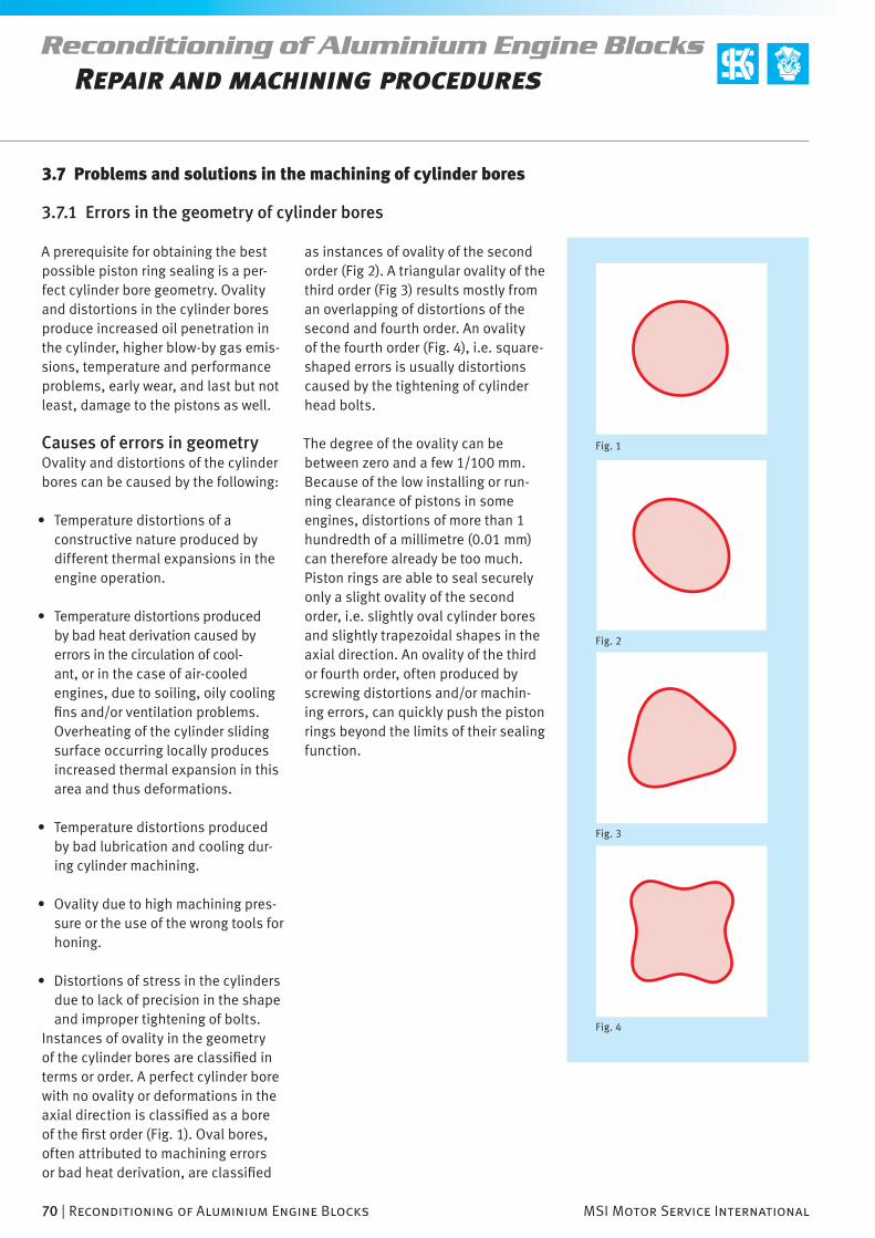
70 | Reconditioning of Aluminium Engine Blocks MSI Motor Service International
Reconditioning of Aluminium Engine BlocksRepair and machining procedures
Fig. 1
Fig. 2
Fig. 3
Fig. 4
3.7 Problems and solutions in the machining of cylinder bores
3.7.1 Errors in the geometry of cylinder bores
A prerequisite for obtaining the best possible piston ring sealing is a per-fect cylinder bore geometry. Ovality and distortions in the cylinder bores produce increased oil penetration in the cylinder, higher blow-by gas emis-sions, temperature and performance problems, early wear, and last but not least, damage to the pistons as well.
Causes of errors in geometryOvality and distortions of the cylinder bores can be caused by the following:
• Temperature distortions of a constructive nature produced by different thermal expansions in the engine operation.
• Temperature distortions produced by bad heat derivation caused by errors in the circulation of cool-ant, or in the case of air-cooled engines, due to soiling, oily cooling fi ns and/or ventilation problems. Overheating of the cylinder sliding surface occurring locally produces increased thermal expansion in this area and thus deformations.
• Temperature distortions produced by bad lubrication and cooling dur-ing cylinder machining.
• Ovality due to high machining pres-sure or the use of the wrong tools for honing.
• Distortions of stress in the cylinders due to lack of precision in the shape and improper tightening of bolts.
Instances of ovality in the geometry of the cylinder bores are classifi ed in terms or order. A perfect cylinder bore with no ovality or deformations in the axial direction is classifi ed as a bore of the fi rst order (Fig. 1). Oval bores, often attributed to machining errors or bad heat derivation, are classifi ed
as instances of ovality of the second order (Fig 2). A triangular ovality of the third order (Fig 3) results mostly from an overlapping of distortions of the second and fourth order. An ovality of the fourth order (Fig. 4), i.e. square-shaped errors is usually distortions caused by the tightening of cylinder head bolts.
The degree of the ovality can be between zero and a few 1/100 mm. Because of the low installing or run-ning clearance of pistons in some engines, distortions of more than 1 hundredth of a millimetre (0.01 mm) can therefore already be too much. Piston rings are able to seal securely only a slight ovality of the second order, i.e. slightly oval cylinder bores and slightly trapezoidal shapes in the axial direction. An ovality of the third or fourth order, often produced by screwing distortions and/or machin-ing errors, can quickly push the piston rings beyond the limits of their sealing function.

MSI Motor Service International Reconditioning of Aluminium Engine Blocks | 71
Reconditioning of Aluminium Engine BlocksRepair and machining procedures
legislation, even new vehicles are required to comply with the correct exhaust gas emission values. Long engine break-in times in which the optimum operating parameters adjust themselves only after the fi rst several thousand kilometres are no longer desired, and are no longer practical.
The mechanical exposing of the silicon crystals within the framework of the fi nishing of ALUSIL® and LOKASIL® cylinder sliding surfaces –in addi-tion to removing the surrounding aluminium and creating tribologically favourable conditions– also serves to provide the piston rings with the opti-mum sliding properties. The relatively sharp edges of the silicon crystals produced by honing are rounded off in the mechanical exposure proc-ess, which can be compared with the traditional engine break-in attrition. When the cylinder sliding surface is being smoothed and the peaks of the silicon crystals are being removed by the piston rings, the rings lose part of their intended properties and product life by early abrasion.
On the other hand, as a result of very hard silicon crystals that have already been optimised in their shape dur-ing machining, the cylinder sliding surface will not change from the fi rst engine start-up for a very long time. This means ovality and other defor-mations in the cylinder surface will not (be able to) be smoothed by the piston rings. This is quite different from the earlier customs in engine construction where the cylinder bore and also the piston rings had to adjust to each other by attrition during en-gine break-in. Therefore the cylinder surfaces were honed roughly and the
Especially in the case of the piston de-signs of more recent models in which the height of the piston rings is nearly 1 mm or even less, the sealing prob-lem increases more with oval cylinder bores. The designed reduction in the height of the piston rings is intended to reduce internal friction losses in the engine and thus to reduce the consumption of fuel. Because of the decreased contact area of such rings on the cylinder wall, the piston ring tension must also be reduced. Other-wise, the specifi c surface pressure of the rings would be too great, and the tribological properties would deterio-rate. Provided that the bore geometry is correct, this designed reduction in piston ring tension does not have any negative impact on the sealing effect. The rings seal very well, produce only slight friction losses, and have a long product life. In the case of oval or distorted cylinders, the reduced piston ring tension, however, causes the rings to adjust very slowly, if at all, to the cylinder wall and thus not to be able to perform their intended sealing function.
In the case of modern engines, the break-in of the parts happens already during machining. In other words, the sliding surfaces of cylinder bores and piston rings are manufactured so that brand new engines have optimum operating conditions right from the start. The surface quality is optimised during production to the extent that already the fi rst time the engine starts there will be practically no attrition caused during engine break-in, and the parts can expect a longer product life.
This is especially important today because due to strict exhaust gas
piston rings had high tangential ten-sions. Today the quality of the cylinder sliding surface almost reaches the op-timum during engine production, and the piston rings work far better and longer than in years gone by, in spite of reduced tangential tension.
In order to obtain the best possible results from the machining of cylin-der sliding surfaces, it is extremely important to know the processes in the engine and the causes of cylinder distortions and ovality. They can be reduced considerably and limited to a minimum during machining with the proper measures.

72 | Reconditioning of Aluminium Engine Blocks MSI Motor Service International
Reconditioning of Aluminium Engine BlocksRepair and machining procedures
Fig. 2
Fig. 1
Fig. 3
Ovality can be produced by deformations and distortions (overheating) during drilling or honing (excessive pres-sure applied by honing stones). Often in order to obtain a good material removal, the cutting pressure on the honing tool is increased beyond the normal amount. This is often the case if the honing stones have become dull. Depending on the construction and thickness of the cylinder wall, the material will give way to the pressure applied by the honing stones. The facts are presented in Figures 1 to 3. In Figure 2 it is evident that the cylinder wall in the area of the water ducts has been temporarly deformed under the high pressure of the honing tool. After machining, the cylinder wall springs back to its original position. In this case the cylinder bore gets an oval shape (Fig. 3).
3.7.2 Errors in cylinder bore geometry due to wrong machining
1. Before machining, the cylinder bore is still basically round
2. Deformation caused by excessive machining pressure
3. After machining, the bore is oval shaped
Important!
To obtain an exact bore geometry in the machining of aluminium, multiple stone honing heads with at least fi ve honing stones distributed around the circumference are required. The use of honing tools with a small amount
of stones, or honing without a precise arrangement of honing stones (for example, in the case of spring-loaded honing tools for the semi-professional fi eld) can cause ovality.

MSI Motor Service International Reconditioning of Aluminium Engine Blocks | 73
Reconditioning of Aluminium Engine BlocksRepair and machining procedures
Trumpet shape can occur if work is done with a honing stone overrun that is too great or with honing stones that are too
Waviness can occur if honing is done with very short honing stones or if a trumpet shape has to be corrected in a narrow area by making the honing tool dwell. Not only will this cause material to be removed in the narrow part, but also in other undesired places inside the bore. If necessary at all, these kinds of corrections should be made only
by dwelling in the narrow place while performing specifi c short strokes at the same time. Experience and good equipment are necessary for such actions to have successful results.
Barrel shapeoccurs when honing is done with honing stones that are too short or with a honing stone overrun that is
Cone shapeis the result of a wrong stroke position. The stone overrun on the side with the larger diameter is too great. Solution: correct the stroke position or use shorter honing stones if the honing
long. Solution: reduce the stone over-run or use shorter honing stones.
too small. Solution: increase the stone overrun or use longer honing stones.
stone overrun is inadequate because of access problems (e.g. in the area of the main bearing gap).

74 | Reconditioning of Aluminium Engine Blocks MSI Motor Service International
Reconditioning of Aluminium Engine BlocksRepair and machining procedures
Fig. 1
As described in Section 2.3.4, “Tightening the cylinder head bolts”, distortions occur in the upper cylinder area when the cylinder head bolts are tightened. In the case of problem engines, especially those that tend to have problems with oil consump-tion, such ovality must be taken into account from the beginning in the machining process.
3.7.3 Cylinder bore ovality caused by bolt distortions
TestIt is easy to check whether there are distortions in the cylinder bores caused by the tightening of bolts, and if so, to what degree. After removing the pistons and the crankshaft drive, the cylinder head is mounted and tightened with the specifi ed tighten-ing torque. The bore gauge is inserted from the crankshaft side in the cylin-der bores to measure them.
SolutionOvality in the cylinder bore in the 1/100 mm range caused by tighten-ing the bolts (please refer to Section 2.3.3, “Tightening the cylinder head bolts”) can be minimised by using a torque plate. A torque plate is com-posed of a steel plate several centi-metres thick (at least 4 cm). Except for the water ducts, it has the same openings as the engine block (Fig.1).
By screwing on the torque plate (including the cylinder head gasket) and tightening the cylinder head bolts with the specifi ed tightening torque, the same tension ratios as if the cylinder head were mounted are created. In this case, distortions in the cylinder bores that could be produced by tightening the cylinder head bolts are defi ned, created and taken into account in the machining process by drilling and honing. This will ensure that the cylinder bores in the later engine operation (correct machining provided) will be as round and cylin-drical as possible.
RecommendationIn order to rule out distortion prob-lems in machining from the outset, and to obtain the best result possible, it‘s generally recommend to use a torque plate. When reconditioning en-gines that tend to distortion problems, some engine reconditioners even go so far as to rinse out the water jacket of the engine block with hot water when machining cylinder bores in order to replicate the conditions pre-vailing in the later engine operation as closely as possible.
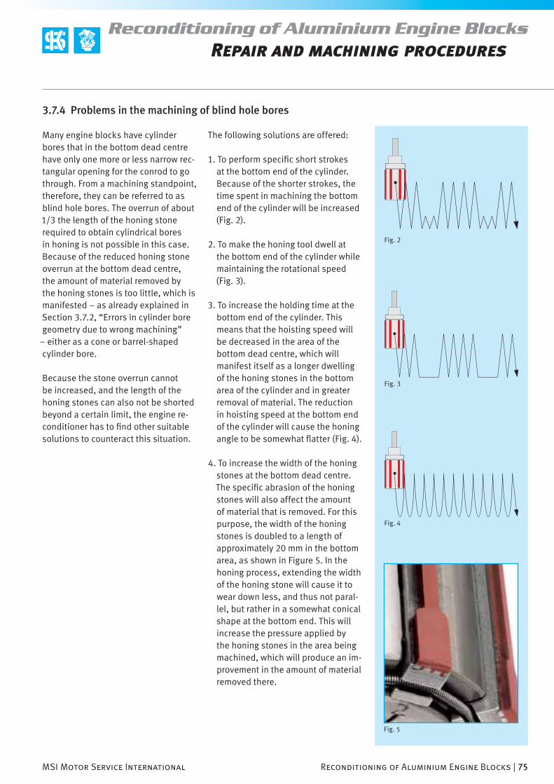
MSI Motor Service International Reconditioning of Aluminium Engine Blocks | 75
Reconditioning of Aluminium Engine BlocksRepair and machining procedures
Fig. 3
Fig. 2
Fig. 4
Fig. 5
3.7.4 Problems in the machining of blind hole bores
Many engine blocks have cylinder bores that in the bottom dead centre have only one more or less narrow rec-tangular opening for the conrod to go through. From a machining standpoint, therefore, they can be referred to as blind hole bores. The overrun of about 1/3 the length of the honing stone required to obtain cylindrical bores in honing is not possible in this case. Because of the reduced honing stone overrun at the bottom dead centre, the amount of material removed by the honing stones is too little, which is manifested – as already explained in Section 3.7.2, “Errors in cylinder bore geometry due to wrong machining”
– either as a cone or barrel-shaped cylinder bore.
Because the stone overrun cannot be increased, and the length of the honing stones can also not be shorted beyond a certain limit, the engine re-conditioner has to fi nd other suitable solutions to counteract this situation.
The following solutions are offered:
1. To perform specifi c short strokes at the bottom end of the cylinder. Because of the shorter strokes, the time spent in machining the bottom end of the cylinder will be increased (Fig. 2).
2. To make the honing tool dwell at the bottom end of the cylinder while maintaining the rotational speed (Fig. 3).
3. To increase the holding time at the bottom end of the cylinder. This means that the hoisting speed will be decreased in the area of the bottom dead centre, which will manifest itself as a longer dwelling of the honing stones in the bottom area of the cylinder and in greater removal of material. The reduction in hoisting speed at the bottom end of the cylinder will cause the honing angle to be somewhat fl atter (Fig. 4).
4. To increase the width of the honing stones at the bottom dead centre. The specifi c abrasion of the honing stones will also affect the amount of material that is removed. For this purpose, the width of the honing stones is doubled to a length of approximately 20 mm in the bottom area, as shown in Figure 5. In the honing process, extending the width of the honing stone will cause it to wear down less, and thus not paral-lel, but rather in a somewhat conical shape at the bottom end. This will increase the pressure applied by the honing stones in the area being machined, which will produce an im-provement in the amount of material removed there.

76 | Reconditioning of Aluminium Engine Blocks MSI Motor Service International
Reconditioning of Aluminium Engine BlocksRepair and machining procedures
Fig. 1
As explained in Sections 2.3.4 and 2.3.5, in some engine constructions the cylinder bores have holes for installing piston pins and openings for crankcase ventilation. When sliding over partially sharp edges, the honing stones wear down more than when they are machining smooth cylinder
3.7.5 Cross-drilled bores in the cylinder wall
surfaces. As already explained in the previous section, the uneven abrasion of the honing stones can be compen-sated by extending the width of the honing stones. In addition, when the honing stones overrun the open-ings, they will follow the shape of the cylinder longer and will not bounce
so easily in the opening. This will increase the product life of the stones and will improve the roundness and the geometry of the cylinder bore.

MSI Motor Service International Reconditioning of Aluminium Engine Blocks | 77
Reconditioning of Aluminium Engine BlocksRepair and machining procedures
Fig. 2
Fig. 3
Fig. 4
3.8 KS Tools for machining aluminium cylinder bores
KS maschining stones for the honing and mechanical exposure processes
For the fi rst time MSI offers the recon-ditioning industry stones for the hon-ing and exposure processes that fully satisfy the necessary requirements for fi nishing aluminium silicon cylinder sliding surfaces. This is cutting and exposure material that is used in the KS engine block series produc-tion, and that is not available in retail tool shops. The use of these tools in compliance with the aforementioned machining parameters will ensure a high degree of process reliability with machining qualities that have not been achieved in the reconditioning sector until now.
The high-quality KS machining stones are durable enough for the profes-
sional machining of several thousand cylinder bores. Adherence to the prescribed machining parameters and proper handling are a prerequisite for obtaining a long product life for the tools.
Because of the plastic bonding, the honing stones can withstand tempera-tures only up to a maximum of 80° C. For this reason the machining stones cannot be welded to a mounting plate. With regard to a long product life we recommend that the KS honing and exposing stones be protected from direct sunlight and constant contact with oil or other chemicals. Therefore, after being used in a machining pro-cedure, the stones must be cleaned of any remaining oil and soiling, and stored in a dark place. Solvents must not be used for cleaning.
Because of the variety and diversity of fi nishing machines and tools that exist in the fi eld, the KS machining stones are supplied as individual units. The machining stones must be attached locally by a professional by gluing (Fig. 2) with a common single or dual-component glue, or by clamp-ing (Fig. 3 and Fig. 4) individually.
Fastening the KS diamond honing stones
Variant 1:Gluing the honing stones to a carrier followed by clamping
1. Glue2. Diamond honing stone3. Mounting plate with groove
4. Clamping screw5. Stone holder with clamp6. Spacer
Variant 2:Clamping the stones

78 | Reconditioning of Aluminium Engine Blocks MSI Motor Service International
Reconditioning of Aluminium Engine BlocksRepair and machining procedures
Fig. 1
Fastening the KS exposing stones
The exposing stones are too soft and porous to be clamped. They can be attached to a holder only by gluing. Common single or dual-component glues that are suffi ciently tough and resistant to oils, acids and alkalines are suitable for gluing.
1. Glue2. Exposing stone3. Mounting plate4.Clamping screw5. Stone holder with clamp
Gluing the exposing stones followed by clamping
Exposing stones cannot be clamped

MSI Motor Service International Reconditioning of Aluminium Engine Blocks | 79
Reconditioning of Aluminium Engine BlocksRepair and machining procedures
Fig. 2
KS diamond honing stones
Product designation KS diamond honing stones
Product information Plastic bonded diamond honing stone
Application Honing of aluminium cylinder sliding surfaces
Dimensions in mm L x B x H 80 x 5 x 6
Height of the metal support 3 mm
Temperature resistance max. 80°C
Minimum number of stones per honing head
5
Manner of fastening the stones
Clamping or gluing
Content of a packaged unit 2 diamond honing stones
KS order number 50 009 908
Note
The special composition of the plastic bonded diamond honing stones is intended only for machining alu-minium materials. Because of the material properties of grey cast iron or other iron materials, they cannot be machined with these honing stones.
Conditioning the honing stones before honingIn order to obtain a fl at contact surface and good machining results with the new stones from the very start, the stones mounted on the honing head should be run in in a grey cast iron cylinder with a comparable diameter and exact bore geometry (performing the honing movements). The hardness of the cylinder will have a certain abrasive effect on the stones, which will cause them to adjust to the shape of the cylinder on the surface and over the length of the stone in a short time. This process could take too long in an aluminium cylinder bore to be reconditioned, and could deteri-orate the geometry of the bore.

80 | Reconditioning of Aluminium Engine Blocks MSI Motor Service International
Reconditioning of Aluminium Engine BlocksRepair and machining procedures
Fig. 1
Fig. 2
KS silicon exposing stones
Product designation KS silicon exposing stones
Product information Exposing stones with abrasive grains of pure corundum, bonded in a porous plastic body.
Application Mechanical Exposing the silicon crystals for ALUSIL® and LOKASIL® cylinder sliding surfaces
Dimensions in mm L x B x H 80 x 10 x 10
Temperature resistance max. 80°C
Manner of fastening the machining stones Fastening by gluing
Content of a packaged unit 2 Freilegungsleisten
KS-Bestellnummer 50 009 909
Note
The edges of the exposing stones should be broken off somewhat before the fi rst use. Use sandpaper to round off the edges on an even surface (Fig. 2).

MSI Motor Service International Reconditioning of Aluminium Engine Blocks | 81
Reconditioning of Aluminium Engine BlocksRepair and machining procedures
Fig. 3
Fig. 4
KS silicon exposing paste
Product designation KS silicon exposing paste
Application Lapping exposing of silicon crystals for Silitec®, ALUSIL® and LOKASIL® cylinder sliding surfaces
Size of package 500 g
KS order number 50 009 907
Felt strips for the lapping exposing
Product designation Felt strips for the vlapping exposing
Application Lapping exposing of silicon crystals for Silitec®, ALUSIL® and LOKASIL® cylinder sliding surfaces
Dimensions in mm L x B x H approx. 89 x 10 x 10
Manner of fastening the felt strips Clamping, Sunnen system
Content of a packaged unit 2 felt strips
KS order number 50 009 863
Hinweis
Weitere Werkzeuge fi nden Sie in unserem KS-Katalog „Werkzeuge und Prüfmittel“.

82 | Reconditioning of Aluminium Engine Blocks MSI Motor Service International

MSI Motor Service International Reconditioning of Aluminium Engine Blocks | 83
Attachment

84 | Reconditioning of Aluminium Engine Blocks MSI Motor Service International
Reconditioning of Aluminium Engine BlocksAttachment
Fig. 1
Fig. 2
The real surface (workpiece surface) separates a body from its environ-ment. (DIN EN ISO 4287)
The sensor intersect process is a tech-nical measuring method for recording a two-dimensional image of a surface. A feeding system moves a scanning unit with constant speed horizontally over the surface. (DIN EN ISO 3274)
The scanned profi le is the shell of the real surface scanned according to the sensor intersect process. Its most important content is distortions in the form: deformations, waviness and roughness. (DIN EN ISO 3274, DIN 4760)
Characteristics, unless otherwise indicated, are defi ned for individual measurement sections. The results are calculated as averages of several individual measurement sections. Five individual measurement sections are considered standard for roughness characteristics. The measurement data for all the measurement sections is used as the basis for characteristic curves and the associated parameters (e.g. material portion). (DIN EN ISO 4288)
4.1 The small study of surfaces
Surface characteristics
Ra, Rq roughness averagesDIN EN ISO 4287, ASME B46.1
The Ra roughness average is the arith-
metic average of the amounts of all the values of the roughness profi le.
The Rq roughness average is the
square average of all values of the roughness profi le.
Z(x) = values of the roughness profi le.
Rz, Rmax depth of roughnessDIN EN ISO 4287, ASME B46.1
The individual roughness depth Rz1 is the sum of the height of the greatest profi le peak and the depth of the gre-atest profi le valley of the roughness profi le within an individual measure-ment section (I
r).
The Rz roughness is the arithmetic average of the individual roughness depth R
z1 of successive individual
measurement sections.
The maximum roughness depth Rmax is the greatest individual roughness depth within all the measurement sec-tions (I
n). (Cf. DIN EN ISO 4288; R
max
corresponding to Rz1max
), Rz, R
max depth

41
2
7
5
6
3
MSI Motor Service International Reconditioning of Aluminium Engine Blocks | 85
Reconditioning of Aluminium Engine BlocksAttachment
Fig. 3
Rk, Rpk, Rvk, Mr1, Mr2
DIN EN ISO 13565-1 and -2
A special fi ltering process that sup-presses ridges produces a roughness profi le according to 13565-1. A special adjustment line on the Abbott curve breaks them down into three areas from which the characteristics are determined according to 13565-2.
The core roughness depth Rk is the
depth of the core roughness profi le.
The reduced peak height Rpk
is the ave-rage height of peaks protruding from the core area.
The reduced ridges depth Rvk
is the average depth of ridges located in the core area.
Mr1
and Mr2
indicate the smallest and largest material portion of the core roughness profi le.
1. Profi le peak area2. Core area3. Profi le ridge area 4. “Peak area”5. Material portion curve (Abbott curve)6. ”Ridge area“7. Material portion

86 | Reconditioning of Aluminium Engine Blocks MSI Motor Service International
Reconditioning of Aluminium Engine BlocksAttachment
Question 1How can a Volkswagen 1.4 litre aluminium engine block with engine ID AHW be reconditioned?
AnswerThis is an engine block with grey cast iron liner inserts. Basically, this kind of cylinder can be drilled and honed the normal way and fi tted with oversized pis-tons. However, the manufacturer specifi es that for AWY, AZQ (3-cylinder, 1.2 l.), AHW, AKQ (4-cylinder, 1.4 l.) and AJV (4-cylinder 1.6 l.) engines the crankshaft and also the balance shafts – if present – do not have to be dismounted. When the bolts of the main bearing covers are loosened, the internal structure of the aluminium main bearing support will relax and the engine block will be defor-med in this area. If the bearing cover bolts have been loosened, according to the manufacturers instructions, the crankcase must be replaced together with the crankshaft, conrod, pistons, etc.
Question 2I have an ALUSIL® engine block that has to be reconditioned. Your catalogue has ALUSIL® sleeves with part numbers 89 190 571 and 89 190 572 from which one can make the necessary liners oneself. But if I have to make all 6 liners and also shrink them in the engine block, this will be very costly. I have diffi culties passing these costs on to the customer. Is there no cheaper solution?
Answer Rebushing the entire engine block is neither necessary nor advisable because ALUSIL® blocks can be rebored and fi tted with oversized pistons. The cylinder sleeves you mentioned can be used if a cylinder sliding surface is so badly da-maged that the block can no longer be repaired by using oversized pistons, for example. For this case there is the solution to use cylinder sleeves from which the engine reconditioner can make a liner with the desired diameter himself to repair a single cylinder.
4.2 Frequently asked questiones

MSI Motor Service International Reconditioning of Aluminium Engine Blocks | 87
Reconditioning of Aluminium Engine BlocksAttachment
Question 3We have an engine block with nickel-coated cylinder sliding surfaces. One of the cylinders is badly damaged. Is it possible to insert an ALUSIL® cylinder liner in this cylinder?
AnswerNo! This is not possible because traditional pistons must be used with nickel-coated cylinder sliding surfaces. But with ALUSIL® cylinder sliding surfaces, iron-coated pistons (Ferrocoat®) are necessary because aluminium pistons do not work in aluminium cylinders. But in the case of the repair mentioned, check to see whether the engine block can be repaired by inserting a grey cast iron liner. The procedure is described in Section 3.2.2., “Installing cylinder liners in aluminium engine blocks”.
Question 4We have repaired an engine block with nickel-coated cylinder sliding surfaces by inserting grey cast iron cylinder liners. Do we have to change something in the piston rings?
AnswerNo change is required to the piston rings when the cylinder surface is changed from nickel to grey cast iron. The series equipment can be retained.
RecommendationWhen grey cast iron liners are used, a change can be made to chrome-coated piston rings. Chrome rings are more resistant to the accumulation of scorch marks, are less sensitive against dirt ingress, and have a higher product life than uncoated cast rings.
Question 5We have always used ceramic honing stones to machine ALUSIL® cylinder sliding surfaces, and have always had good results. Can we repair newer engines with ALUSIL® cylinder sliding surfaces the same way?
AnswerNowadays there are far greater demands on the cylinder sliding surface than there were 15 years ago. When ceramic stones are used in the machining pro-cess, the rate of destruction of the silicon crystals will be from 40% to 60%. This is intolerable for modern engines because the design of the pistons and rings has also changed. For the machining of ALUSIL® cylinder sliding surfaces, it‘s still recommend that only the synthetic resin bonded diamond cutting stones developed by KS be used (please refer to Section 3.8. “KS tools for machining aluminium cylinder bores”).

88 | Reconditioning of Aluminium Engine Blocks MSI Motor Service International
Reconditioning of Aluminium Engine Blocks
Question 6A client has ordered the reconditioning of the engine of an vintage car with a V8 engine block and nickel-coated cylinder sliding surfaces. The customer wants the cylinder sliding surfaces to be machined authentically by redrilling followed by nickel coating. Is it even possible to reapply a nickel coating?
AnswerTo fi nd a company that can recoat such an engine block with nickel for this purpose will be very diffi cult, if not impossible. Usually, nickel recoating is not worth the effort and high costs. As a nickel recoating cannot be performed under the conditions of series production, no guarantees can be given with respect to the thickness and durability of the coating. Depending on the proper-ties of the fuel (sulphur content) a separation of the nickel coating during engine operation cannot be ruled out. The worst-case scenario would be damage to the engine.
Furthermore, no oversized pistons are provided or available for such engines. This means that the pistons have to be made specially, which can also be very costly and still not authentic. For individual cylinders with nickel or chrome coa-ting, there are several specialist companies that generally offer such services for motorcycles. We recommend a search for „Nikasil“ in the Internet.
NoteOf course, to insert grey cast iron liners in a cylinder that was previously coated with nickel is not very authentic. Especially when the engine is a collector‘s item. But in view of the anticipated costs, a professionally inserted grey cast iron liner represents an inexpensive and technically sound replacement solution.
Question 7We want to recondition an aluminium engine block in which the sliding sur-faces were previously nickel-coated by inserting grey cast iron liners. For grey cast iron engine blocks we cold press-in the liners with an overlap of 0.02 to 0.08 mm. Can this procedure be used for an aluminium block as well?
AnswerAluminium and grey cast iron have extremely different thermal expansion behaviours. During operation, the aluminium cylinder block will expand much more than the grey cast iron cylinder liner inserted. The overlap mentioned would not provide a reliable fi t for the grey cast iron cylinder liner in the alu-minium block. The liner could come loose during engine operation and cause damage to the engine. Cold pressing of the liner, as is done with grey cast iron engine blocks, is not possible with aluminium engine blocks because the liner will seize halfway into the cylinder counterbore and the applied pressure could increase to such an extent that the engine block would be destroyed. For this reason we recommend that grey cast iron liners with an overlap of 0.08 to 0.1 mm be shrunk into the engine block as described in Section 3.2.
“Installing aluminium and grey cast iron cylinder liners”.
Attachment

MSI Motor Service International Reconditioning of Aluminium Engine Blocks | 89
Reconditioning of Aluminium Engine Blocks
Question 8Can aluminium engine blocks be welded?
AnswerThat depends on the type of damage. In principle, welding is possible on an aluminium engine block. But material distortions can occur in the process the magnitude of which would depend on the scope of the welding. Welding a bro-ken support or stripped threading on the exterior of the engine block should not present any special problem. But damages on or near the cylinder bores could cause material distortions or structural changes that would render the engine block useless.
Aluminium welding jobs should generally be performed by professionals with the necessary experience and appropriate equipment. Here it must also be no-ted that the additional material to be used in the welding should have the same alloy composition as the engine block.
A prerequisite for welding is that the engine block fi rst be warmed up to approxi-mately 150° C. After welding, the engine block should be cooled off in a furnace. It should defi nitely be allowed to cool off for at least 3 to 4 hours. This can be done only in a furnace in which the temperature drops gradually to room tempe-rature. This will minimise or prevent excessive tensions within the structure and cracking as the welded areas cool off.
Question 9Can damaged threads for cylinder head bolts be repaired?
AnswerA repair is possible using common threading repair kits. When a steel thread insert is being inserted, care must be taken to ensure that it has the same length as the original threading. A steel thread insert is much stronger than one of aluminium, but the insert must also be anchored securely in the engine block. This can be done only if the thread insert is long enough.
Attachment

90 | Reconditioning of Aluminium Engine Blocks MSI Motor Service International
Reconditioning of Aluminium Engine Blocks
Article-No. Language
50 003 728 german
50 003 727 english
50 003 726 french
Article-No. Language
50 003 725 spanish
50 003 724 italian
50 003 700 russian
Article-No. Language
50 003 823 german
50 003 822 english
50 003 821 french
50 003 820 spanish
50 003 819 italian
Article-No. Language
50 003 973-01 german
50 003 973-02 english
50 003 973-03 french
Article-No. Language
50 003 734 german
50 003 733 english
50 003 732 french
Article-No. Language
50 003 731 spanish
50 003 580 russian
Article-No. Language
50 003 973-04 spanish
50 003 973-09 russian
Article-No. Language
50 003 818 arabian
50 003 817 portuguese
50 003 816 turkish
50 003 815 russian
50 003 814 czech
Attachment
4.3 Technical brochures
Article-No. Language
50 003 804-01 german
50 003 804-02 english
50 003 804-03 french
Article-No. Language
50 003 804-04 spanish
50 003 804-09 russian
Piston damagesRecognising and rectifying
Product Manual – Engine componentsBasic technical information on all KS product groups
Honing of Gray Cast Iron Cylinder Blocks
Reconditioning of Aluminium EnginesBrochure
Valve Seat InsertsTechnical information and assembly instructions
Additional languages upon request.

MSI Motor Service International Reconditioning of Aluminium Engine Blocks | 91
Reconditioning of Aluminium Engine Blocks
Article-No. Language
50 003 596-01 german
50 003 596-02 english
50 003 596-03 french
Article-No. Language
50 003 596-04 spanish
50 003 596-09 russian
Article-No. Language
50 003 939-01 german
50 003 939-02 english
50 003 939-03 french
Article-No. Language
50 003 939-04 spanish
50 003 939-09 russian
Article-No. Language
50 003 605-01 german
50 003 605-02 english
50 003 605-03 french
Article-No. Language
50 003 605-04 spanish
50 003 605-09 russian
Article-No. Language
50 003 931-01 german
50 003 931-02 english
50 003 931-03 french
Article-No. Language50 003 931-04 spanish
50 003 931-09 russian
Attachment
Tools & Testing Instruments
Technical Filter Booklet
Oil Consumption and Loss of Oil
Interior Compartment Filter

92 | Reconditioning of Aluminium Engine Blocks MSI Motor Service International
Reconditioning of Aluminium Engine Blocks
Pull-out technical dataThe following pages can be pulled out so that you can have all the necessary information on hand while working.
Language Pistons Rings Bearings
german 50 003 842 50 003 717 50 003 999
french 50 003 840 50 003 715 50 003 996
spanish 50 003 839 50 003 714 50 003 997
italian 50 003 834 50 003 708 50 003 843
arabian 50 003 838 50 003 712 50 003 995
portuguese 50 003 837 50 003 713 50 003 846
russian 50 003 835 50 003 710 50 003 844
english 50 003 841 50 003 716 50 003 998
Attachment
Piston damages / Oil Consumption & Loss of Oil Valve damagesPoster, 594 x 840 cm (DIN A1)
Language Piston damages Oil Consumption &Loss of Oil
Valve damages
german 50 003 974-01 50 003 975-01 50 003 976-01
english 50 003 974-02 50 003 975-02 50 003 976-02
french 50 003 974-03 50 003 975-03 50 003 976-03
spanish 50 003 974-04 50 003 975-04 50 003 976-04
russian 50 003 974-09 50 003 975-09 50 003 976-09
Installation of Pistons / Rings / BearingsPane, 70 x 100 cm, with attachment eyes

MSI Motor Service International Reconditioning of Aluminium Engine Blocks | 93
Reconditioning of Aluminium Engine Blocks
Tool: Drilling tools equipped with PCD inserts (PCD = polycrystalline diamonds)
Work steps: Step 1 Align the engine block on the fi nishing machineStep 2 Drill the cylinder bore up to 0.5 mm short of the fi nal dimension of the cylinder Material removal per drilling event and per cylinder maximum 0.5 mm.Step 3 Drill the cylinder bore up to 0.3 mm short of the fi nal dimension of the cylinder (next-to-last drilling operation) material removal per cylinder side maximum 0.1 mm.Step 4 Drill the cylinder bore up to 0.1 mm short of the fi nal dimension of the cylinder (last drilling operation) material removal per cylinder side maximum 0.1 mm. The thickness of the remaining wall required for honing is 0.33 to 0.55 mm.Step 5 Remove the burrs from the top end of the cylinder by chamfering (Fig. xxx).
Machining parameters for drilling cylinders Value
Recommended cutting speed (PCD cutter) 400 m/min
Machining speed based on the cylinder diameter Ø 1/min
80 mm 1600
85 mm 1480
90 mm 1420
95 mm 1340
100 mm 1270
Material removal of the next-to-last drilling 0.1 mm
Material removal of the last drilling 0.1 mm
Cutter feed per rotation (single-blade cutter) 0.1 mm
Target surface roughness (Rz) 3.5–4.5 µm
Material removal required of honing 0.03 to 0.05 mm
Rake angle of cutter edge 10°
Cutter edge clearance angle 10°
Nose radius of cutter edge 0.8–1.0 mm
Excerpt from the brochure ”Reconditioning of Aluminium Blocks“ Section 3.4 Fine drilling the cylinders
Note
To keep the rate of destruc-tion of the silicon crystals in the cylinder wall to a minimum, the fi ne drilling of the cylinder bores must be done with PCD cutters. Only when faultless PCD cutters are used is it pos-
sible to ensure that silicon crystals embedded in the aluminium matrix will be cut precisely and properly, and will not be torn.
To avoid thermal problems, we recommend the use of cooling lubricant (oil/water
emulsion) when drilling. Cooling lubricant is also used in the series produc-tion of aluminium engine blocks, which improves the surface quality of the cylin-der bores as well as the product life of the cutters.
Fine drilling of aluminium cylinder bores (Alusil®, Lokasil®, etc.)

MSI Motor Service International

MSI Motor Service International Reconditioning of Aluminium Engine Blocks | 95
Reconditioning of Aluminium Engine Blocks
Tool: KS diamond honing stones, KS part no. 50 009 908Cooling lubricant: Honing oil (do not use oil/water emulsion)
Work steps Step 1 Align the engine block on the fi nishing machine.Step 2 Set the machine parameters (rotational speed, hoisting speed, stroke position, etc.)Step 3 Hone the cylinder bore for 30 seconds at the maximum.Step 4 Stop the honing and move the tool away from the surface of the cylinder bore briefl y to rinse and moisten the stones with oil. (important)Step 5 If necessary, check the measurement of the cylinder diameter to estimate the amount of material removed.Step 6 Continue honing with steps 3 to 5 until the fi nal cylinder diameter is reached.
Important!
To prevent the stones from being clogged with rubbed-on aluminium particles, and to improve lubrication, honing should be interrupted briefly
after each 30 seconds. Contact of the stones with the cylinder wall should be interrupted. The work should be continued only after the cutting surface
has been wetted and rinsed with honing oil. In order for the stones to wear evenly, in series production the rotational direction of the honing
tool is reversed each time a new cylinder bore is machined.
Honing with KS diamond honing stones bonded with synthetic resin should
take at least 90 seconds per cylinder bore. Shorter machining times indicate
excessive pressure applied to the honing stones and will result in increased
wear on the stones.
Machining parameters for honing Value
Recommended rotational speed for honing 250–350 1/min
Minimum rotational speed for honing 200 1/min
Maximum rotational speed for honing 400 1/min
Hoisting speed of the honing head based on the Rotational speed 1/min m/min
400 16
350 14
300 12
200 8
Honing angle (product of rotation speed and hoisting speed) 15–20°
Required material removal based on the diameter of the cylinder 0.06 bis 0.1 mm
Recommended pressure applied to honing stone 30 N/cm²
Maximum pressure applied to honing stone 40 N/cm²
Total machining time per cylinder bore (guideline) > = 90 s
Target surface roughness (Ra) 0.06–0.1 µm
Honing stone overrun in TDC and BDC based on the length of the honing stone max. 30 %
Target degree of destruction of silicon crystals 5–10 %
Maximum admissible degree of destruction of silicon crystals max. 30 %
Admissible ovality of cylinder bores (production tolerance) +/– 6 µm
Honing aluminium cylinder sliding surfaces (Alusil®, Lokasil®, etc.)
Excerpt from the brochure ”Reconditioning of Aluminium Blocks“ Chapter 3.5 „Honing“

MSI Motor Service International

MSI Motor Service International Reconditioning of Aluminium Engine Blocks | 97
Reconditioning of Aluminium Engine Blocks
Excerpt from the brochure „Reconditioning of Aluminium Blocks“ Section 3.6 ”Exposing the silicon crystals“
*** To expose the silicon crystals on all sides, in the mechanical exposure pro-cess the rotational direction
of the tool must be changed every 30 seconds.
Note
In the event of exces-sive, rapid abrasion of the exposing stones, the
pressure applied may be too great and may have to be reduced. If used prop-
Machining parameters for the mechanical exposure process Value
Recommended rotational speed for the exposure process approx. 200 1/min
Hoisting speed approx. 8 m/min
Stone overrun based on the length of the stone max. 15 %
Exposure angle (honing angle) 15–20°
Change in diameter of cylinder caused by the mechanical exposure < 1 µm
Recommended pressure applied by honing stone 30 N/cm²
Recommended depth of exposure (Rpk
) > = 0.4 µm
Minimum depth of exposure (Rpk
) 0.3 µm
Recommend duration of exposure process 2 x 30 s ***
Cooling lubricant (do not use oil/water emulsion) Honing oil
erly, the exposing stones – despite their softness and porosity – will have a prod-
uct life of several hundred cylinder bores.
Tool: KS exposing stones, KS part no. 50 009 909Cooling lubricant: Honing oil (do not use oil/water emulsion)
Work steps: Step 1 Set the machine parameters (rotational speed, hoisting speed, stroke position, etc.)Step 2 Proceed with the exposure of the silicon crystals for 30 seconds.Step 3 Stop the exposure process and continue machining in the reverse direction in order to obtain an even exposure of the silicon crystals on all sides. (important) Step 4 Check the depth of the exposure with a roughness tester. If necessary, repeat the exposure process (steps 2 and 3) until the necessary exposure depth is reached.
Mechanical exposure of the silicon crystals (Alusil® und Lokasil®)

MSI Motor Service International
MSI Motor Service International Reconditioning of Aluminium Engine Blocks | 99
Reconditioning of Aluminium Engine Blocks
MSI Motor Service International
… immer aktuell !
Unsere Stärke, Ihr Profi t
Das MSI-Schulungsprogramm …Jährlich profi tieren rd. 4500 Mechaniker und Techniker von unseren Schulungenund Seminaren, die wir weltweit vor Ort oder auch in unserem Schulungszentrumin Dormagen (Deutschland) durchführen.
Know-how aus erster Hand …Als Vertriebsorganisation der Kolbenschmidt Pierburg AG liefern wir Ihnen das Knowhow zu unseren Komponenten, Modulen uns Systemen rund um den Motor
… Fachwissen, direkt von Hersteller !www.msi-motor-service.com/schulungen
Technische Informationen …Mit den Produkt-Informationen, Service-Informationen, Broschüren „Service Tipps& Infos“ und Lehrtafeln sind Sie auf dem neuesten Stand der Technik.
… Informationen aus der Praxis, für die Praxis !www.msi-motor-service.com/broschueren
MSI News …Aktuelle Themen, Informationen, Meldungen, Neuprodukte
… Informationen aus erster Hand !www.msi-motor-service.com/aktuelles
Kataloge, MSI-CD, TecDoc-CD …Mit unseren umfangreichen Katalogen, ob auf CD oder gedruckt, fi nden Sieimmer das richtige Teil zum richtigen Fahrzeug
… sicher und schnell !www.msi-motor-service.com/katalog
MSI Online Shop …der noch schnellere Zugang zu den aktuellen Produktdaten, volles Programm
… immer topaktuell !www.onlineshop.msi-motor-service.com
Ihr direkter Zugang zu unserem Leistungsprogramm …www.msi-motor-service.com

KOLBENSCHMIDT PIERBURG
MSI Motor Service International GmbH
Untere NeckarstraßeD-74172 NeckarsulmPhone +49 71 32-33 33 33Fax +49 71 32-33 28 64
Hamburger Straße 15D-41540 DormagenPhone +49 21 33-2 67-100Fax +49 21 33-2 67-111
50 003 804-02 08/06