recommended usage of dsdiff version 1.5 - sonic · pdf filerecommended usage of dsdiff version...
TRANSCRIPT
Philips Intellectual Property & Standards
Recommended usage of DSDIFF version 1.5
Version 1
Recommended usage of DSDIFF version 1.5
Version 1 2 2004-04-27
Title: Recommended usage of DSDIFF version 1.5 Version: 1 Date: 2004-04-27
DISCLAIMER Whereas Philips has taken care to ensure that the information contained in this document is accurate, this information is provided on an "as is" basis, without any warranty as to its completeness or accuracy. Royal Philips Electronics shall not be liable in any manner whatsoever for any damages, including direct, indirect or consequential, resulting from the use of this document or reliance on the accuracy of its contents. Supply of this document does not confer any license under any intellectual property right of Royal Philips Electronics to use any of those rights in any apparatus, system or any components, subassemblies or software for such apparatus or system. For any further explanation of the contents of this document, or in case of any perceived inconsistency or ambiguity of interpretation, please consult: Philips Intellectual Property & Standards System Standards and Technology Optical Storage and DRM / Super Audio CD Building SFF-8 P.O. Box 80002 5600 JB Eindhoven The Netherlands Fax.: +31 40 27 34965 or send an E-mail to: [email protected]
© Royal Philips Electronics N.V. 2002-2004 All rights reserved. Reproduction in whole or in part is prohibited without the written consent of the copyright owner.

Recommended usage of DSDIFF version 1.5 Contents
Version 1 3 2004-04-27
Contents
1 Introduction 5 1.1 PURPOSE AND SCOPE 5 1.2 DEFINITIONS, ACRONYMS AND ABBREVIATIONS 5 1.3 REFERENCES 6 1.4 DOCUMENT HISTORY 6
2 The content creation process 7 2.1 RECORDING 8 2.2 EDITING – MIXING – SOUND MASTERING 8 2.2.1 Channel conf igurations in Edited Masters 9 2.2.2 The Marker offset field 10 2.3 DST ENCODING 13 2.3.1 Checking the DST encoding algorithm 13 2.4 AUTHORING 15
3 File system limitations 16 3.1 INTRODUCTION 16 3.2 THE DIVISION METHOD 16
4 Time File 18
4.1 INTRODUCTION 18 4.2 EXTENSION OF A T IME F ILE 18 4.3 REQUIRED CHUNKS IN A T IME F ILE 19 4.4 RESTRICTIONS ON A TIME F ILE 19 4.5 IDENTIFICATION OF A TIME F ILE 19
5 File History 20
5.1 INTRODUCTION 20 5.2 FILE REVISION INFORMATION 20 5.2.1 Edited Masters 20 5.2.2 Time Files 21 5.2.3 Relation between Edited Master and Time Files 21 5.3 EXAMPLES OF USAGE OF COMMENTS 22
Recommended usage of DSDIFF version 1.5 Contents
Version 1 4 2004-04-27
Appendix A : The CRC algorithm 24
Recommended usage of DSDIFF version 1.5 Introduction
Version 1 5 2004-04-27
1 Introduction
1.1 PURPOSE AND SCOPE
This document describes the typical usage of the DSDIFF file format, a standard file format for storing DSD material [DSDIFF]. The specification is system independent, so applications across various computer platforms can use DSDIFF files. In the specification of DSDIFF [DSDIFF] chunks are defined. Some of these chunks are optional. Within this document recommendations of how and when to use the various chunks are given. Furthermore guidelines are given of how to use DSDIFF in the Super Audio CD production chain.
1.2 DEFINITIONS, ACRONYMS AND ABBREVIATIONS
CD Compact Disc CRC Cyclic Redundancy Check DSD Direct Stream Digital DSDIFF Direct Stream Digital Interchange File Format DSD File DSDIFF file containing DSD audio DST Direct Stream Transfer
Format for lossless encoded DSD audio DST File DSDIFF file containing DST encoded audio DST Frame 1/75 second of DST encoded audio
The time corresponds to the Super Audio CD Frame time Actual length in bytes is variable
EDL Edit Decision List Fs Sampling frequency for CD, being 44100Hz GMT Greenwich Mean Time IFF Interchange File Format PCM Pulse Code Modulation Silence Pattern A digitally generated DSD pattern with the following
properties: • all Channel Bytes have the same value • each Channel Byte contains 4 bits equal to zero and 4
bits equal to one Super Audio CD Frame 1/75 second of audio (is equal to CD frame length)
At 64×fs a frame covers 37632 DSD samples per channel Time File DSDIFF file containing marker information, without sound data
Recommended usage of DSDIFF version 1.5 Introduction
Version 1 6 2004-04-27
1.3 REFERENCES
[DSDIFF] Direct Stream Digital Interchange File Format, Philips, Version 1.5 / April 2004 [ScarletBook] Super Audio CD Standard (Part 2) Sony/Philips [SONYText] The Specification of the STT File Format Sony – Super Audio CD Business Centre
1.4 DOCUMENT HISTORY
Date Version Most important updates 2002-08-05 1.4/1 Initial document 2002-08-09 1.4/2 Added:
• Recommendation DST Sound Index Chunk (section 2.3) Changed:
• Recommendation EMID (section 2.2) 2002-12-03 1.4/3 Added:
• Explanation about marker offset field (section 2.2.2) • Time File Definition (chapter 4)
Changed: • Authoring Recommendation (section 2.4) • File Revision information (section 5.2)
2003-01-23 1.4/4 Changed: • Size of a division file (section 3.1)
2004-04-27 1.5/1 Added: • Relation between Edited Masters and Time files
(section 5.2.3) • Recommendations to use plain DSD in Edited Master
(section 2.4) Changed:
• Text changes in Naming Edited Masters and Time Files (section 5.2.1 and 5.2.2)
Removed: • Versions numbers of reference documents (section 1.3)
Recommended usage of DSDIFF version 1.5 The content creation process
Version 1 7 2004-04-27
2 The content creation process
Recording
EditingMixing
Sound Mastering
AuthoringEncoding
DiscManufacturing
DSDIFF generation
DSDIFF input
sound
Super Audio CD
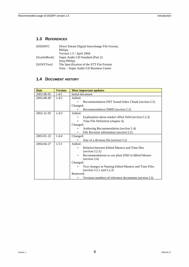
Figure 1: Schematic view of the disc content creation process
The content creation process consists of various stages. In this document the following process steps for creating a Super Audio CD disc [ScarletBook] are distinguished: 1) Recording 2) Editing – Mixing - Sound Mastering 3) Encoding 4) Authoring 5) Disc Manufacturing According to [DSDIFF] not all chunks are required in a DSDIFF file. In this chapter additional information can be found on how to use the optional chunks within a particular stage of the content creation process. The output of authoring and the input and output of the disc manufacturing are not described in this document, because the DSDIFF format is not used in those steps.
Recommended usage of DSDIFF version 1.5 The content creation process
Version 1 8 2004-04-27
2.1 RECORDING
DSD
DSDA/D
Converter
DSD recorder DSDFiles
Analogue live
DSD
D/DConverter
digital (PCM)
DSDA/DConverterAnalogue tape
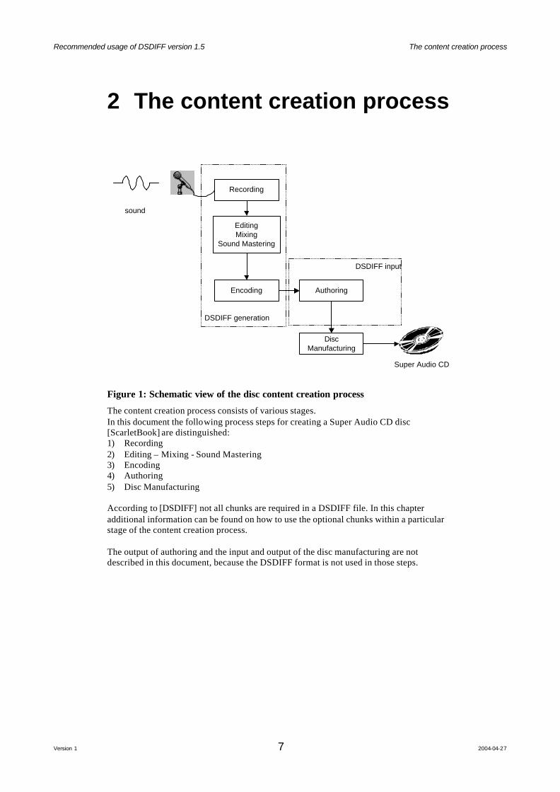
Figure 2: Schematic overview of a recorder set up with different sound sources.
There are different kind of sound sources for recording DSD signals (see Figure 2). To keep track of the used sound source the File History Sound Source Comment is defined. The following kinds of sound source types are defined within DSDIFF: • DSD, sound data directly recorded in DSD during a live recording • Analogue, sound data converted from an original recording on analogue tape • PCM, sound data converted from an original recording in the PCM domain Recommended information in a DSD file after recording: • Absolute Start time
The start time of recording within the time line • Channel ID's according to the loudspeaker set-up
If the recording is not made in such a way that it corresponds with a loudspeaker configuration defined in [DSDIFF] then the C001...C999 identifiers must be used; channel comments can be generated describing the channel contents (e.g. guitar, …)
• Comment – General Remark Description of the recording
• Comment – Operator The name or User Identification of the recording engineer
• Comment - Sound Source [DSD, Analogue, PCM] • Comment - Creating machine
The name and version of the recorder application
2.2 EDITING – MIXING – SOUND MASTERING
The Editing, Mixing and Sound Mastering processes are closely related to each other. The different steps are not chronological, the order of these phases is an artistic decision. Furthermore the tools to perform these phases can be incorporated in one machine.

Recommended usage of DSDIFF version 1.5 The content creation process
Version 1 9 2004-04-27
DSDFiles
5- or 6-channelDSD File
DSD
DSD
2-channelDSD FileDSD
DSD-Editor-Mixer
-SoundMasterconsole
Figure 3: Schematic view of the Editing – Mixing - Sound Mastering processes
Recommended information in a DSD file after Editing – Mixing – Sound Mastering: • Absolute Start time • Channel ID's • Loudspeaker Configuration • Markers
Track information, time and a description for the tracks on the disc • Title
Working title of the disc, for identification purposes • Artist
Name of the artist, for identification purposes • Edited Master ID
Identification for this production, for identification purposes. • Comment – Operator
User who created the Edited Master • Comment - Sound Source
Original sound sources, retrieved from the recording stage • Comment - Creating machine
Application or system which created the Edited Master. For the specification of Edited Masters see [DSDIFF].
2.2.1 Channel configurations in Edited Masters
The Edited Master files are described in [DSDIFF]. The post production processes together will deliver at most 2 Edited Masters. An Edited Master contains the sound data and timing information to create one area on a disc. For each of the following areas a Edited Master is generated (if the area exists): • 2-channel area • 5-channel area or 6-channel area

Recommended usage of DSDIFF version 1.5 The content creation process
Version 1 10 2004-04-27
Within an Edited Master the following channel configurations per track are possible: number of channels in file
number of used channels per track
channels in the file used channels TrackFlags
2 2 SLFT, MRGT SLFT, MRGT 5 3 MLFT, MRGT, C,
LS, RS MLFT, MRGT, C TMF2_Mute
6 3 MLFT, MRGT, C, LFE, LS, RS
MLFT, MRGT, C TMF2_Mute, TMF4_Mute
6 4 MLFT, MRGT, C, LFE, LS, RS
MLFT, MRGT, C, LFE TMF2_Mute
5 4 MLFT, M RGT, C, LS, RS
MLFT, MRGT, LS, RS TMF3_Mute
6 4 MLFT, MRGT, C, LFE, LS, RS
MLFT, MRGT, LS, RS TMF3_Mute, TMF4_Mute
6 5 MLFT, MRGT, C, LFE, LS, RS
MLFT, MRGT, LFE, LS, RS
TMF3_Mute
5 5 MLFT, MRGT, C, LS, RS
MLFT, MRGT, C, LS, RS
6 5 MLFT, MRGT, C, LFE, LS, RS
MLFT, MRGT, C, LS, RS
TMF4_Mute
6 6 MLFT, MRGT, C, LFE, LS, RS
MLFT, MRGT, C, LFE, LS, RS
Table 1: Possible channel configurations per track within an Edited Master.
Note 1: An Edited Master is restricted to 2,5 or 6 channels per file with a fixed channel identification. When a different amount of channels is wanted, the unused channels must still exist and must be filled with silence patterns. Denoting that a channel contains "digital silence" can be done with Track Mute flags. Note 2: Other channel configurations are not allowed. It is recommended that each Edited Master has a unique EMID. The 2-channel Edited Master and the multi-channel Edited Master must have different EMID's even if they belong to the same title (or disc). See also Authoring, paragraph 2.4.
2.2.2 The Marker offset field
In the Super Audio CD specification [ScarletBook] it is stated : It is recommended that both the fade-in and fade-out times of a SuperAudio CD player are less than 50ms. This means e.g. that the first notes of music may be masked by the fade-in of Super Audio CD players.
Recommended usage of DSDIFF version 1.5 The content creation process
Version 1 11 2004-04-27
Trac
kSta
rtfull output
no output
Data signal in
fade-in
Sou
nd S
tart
Data signal out
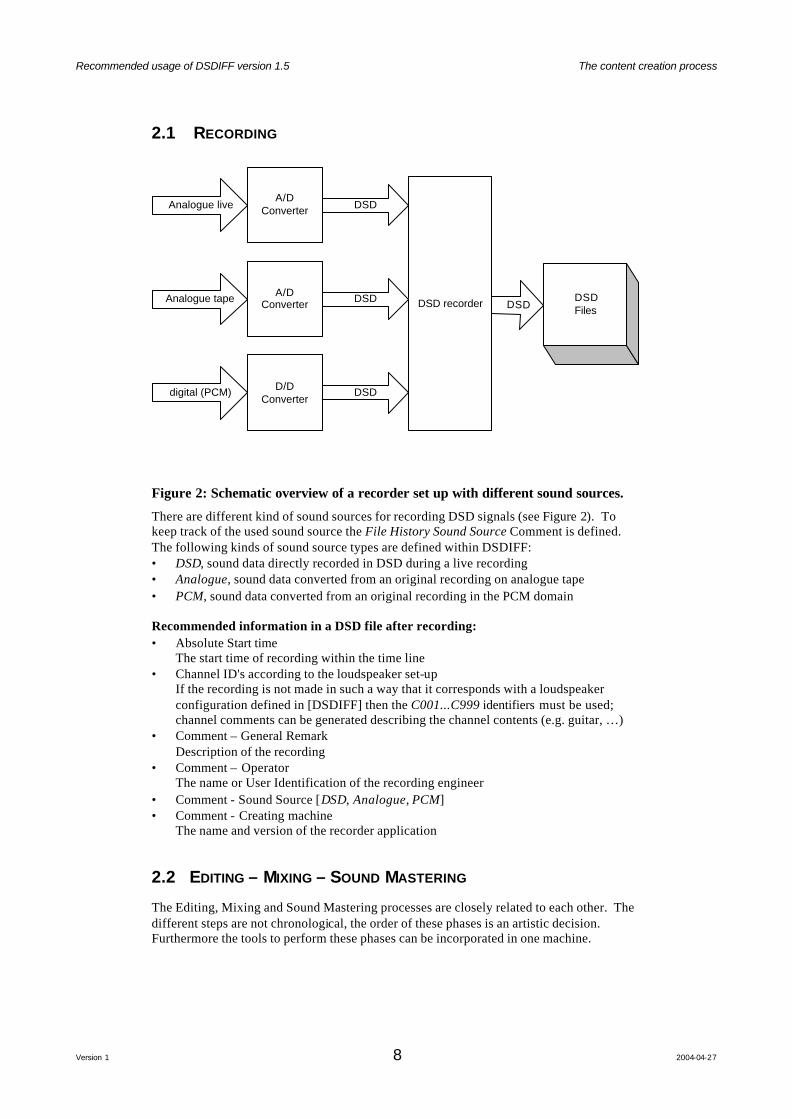
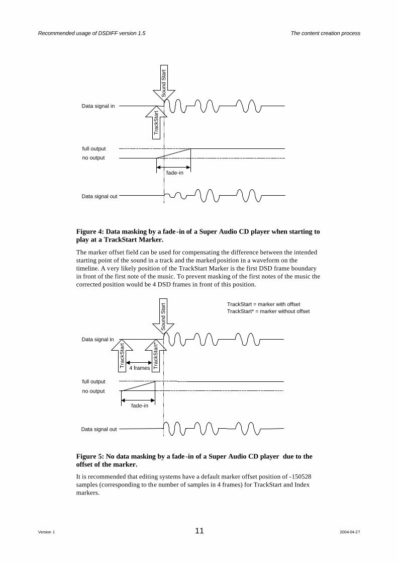
Figure 4: Data masking by a fade -in of a Super Audio CD player when starting to play at a TrackStart Marker.
The marker offset field can be used for compensating the difference between the intended starting point of the sound in a track and the marked position in a waveform on the timeline. A very likely position of the TrackStart Marker is the first DSD frame boundary in front of the first note of the music. To prevent masking of the first notes of the music the corrected position would be 4 DSD frames in front of this position.
Tra
ckS
tart
*
full output
no output
Data signal in
fade-in
Sou
nd S
tart
Data signal out
Tra
ckS
tart
4 frames
TrackStart* = marker without offsetTrackStart = marker with offset
Figure 5: No data masking by a fade -in of a Super Audio CD player due to the offset of the marker. It is recommended that editing systems have a default marker offset position of -150528 samples (corresponding to the number of samples in 4 frames) for TrackStart and Index markers.

Recommended usage of DSDIFF version 1.5 The content creation process
Version 1 12 2004-04-27
Note: resulting marker positions (marker plus offset) must always designate a point within the sound file.
Recommended usage of DSDIFF version 1.5 The content creation process
Version 1 13 2004-04-27
2.3 DST ENCODING
The encoding process compresses DSD data resulting in DST data. The compression algorithm is lossless: the process is reversible.
DSTEncoder
DST FileDSTDSD File DSD
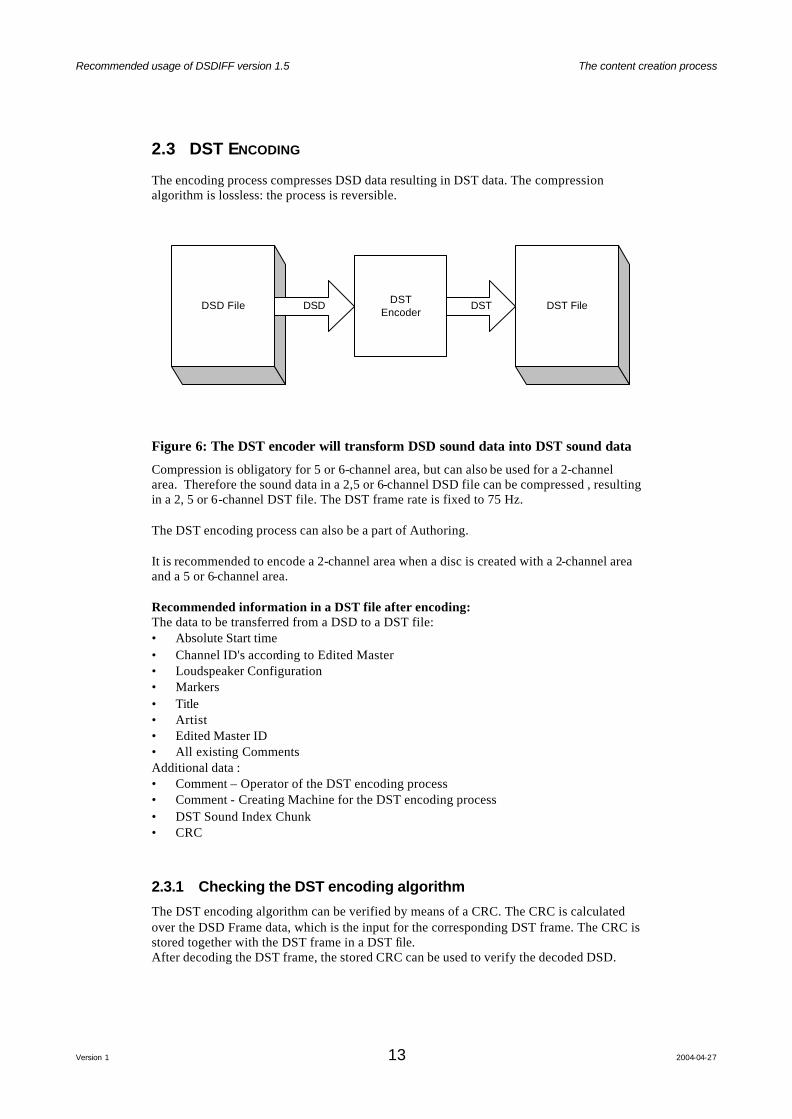
Figure 6: The DST encoder will transform DSD sound data into DST sound data
Compression is obligatory for 5 or 6-channel area, but can also be used for a 2-channel area. Therefore the sound data in a 2,5 or 6-channel DSD file can be compressed , resulting in a 2, 5 or 6-channel DST file. The DST frame rate is fixed to 75 Hz. The DST encoding process can also be a part of Authoring. It is recommended to encode a 2-channel area when a disc is created with a 2-channel area and a 5 or 6-channel area. Recommended information in a DST file after encoding: The data to be transferred from a DSD to a DST file: • Absolute Start time • Channel ID's according to Edited Master • Loudspeaker Configuration • Markers • Title • Artist • Edited Master ID • All existing Comments Additional data : • Comment – Operator of the DST encoding process • Comment - Creating Machine for the DST encoding process • DST Sound Index Chunk • CRC
2.3.1 Checking the DST encoding algorithm
The DST encoding algorithm can be verified by means of a CRC. The CRC is calculated over the DSD Frame data, which is the input for the corresponding DST frame. The CRC is stored together with the DST frame in a DST file. After decoding the DST frame, the stored CRC can be used to verify the decoded DSD.

Recommended usage of DSDIFF version 1.5 The content creation process
Version 1 14 2004-04-27
An implementation example of the CRC algorithm can be found in "Appendix A : The CRC algorithm".
DSTEncoder
DST File
DST
DSD File
CRCCalculation CRC
CRCVerification
DSTDecoder
DS
D
DST
CRC
DSD
Writing Reading
Figure 7: The DST encoder with CRC checking of the DST encoding algorithm.

Recommended usage of DSDIFF version 1.5 The content creation process
Version 1 15 2004-04-27
2.4 AUTHORING
Authoring will use DSDIFF files as input format for the sound data together with the time information. The input for Authoring will be a 2-channel Edited Master for the 2-channel area and a 5-channel or 6-channel Edited Master for the 5 or 6-channel area.
Authoring Disc ImageDSD or DST5/6 channel
File
Ext
ra D
ata
STT File Text Information
DSD or DST2-channel
File
DSD/DST
DSD/DST
Figure 8: Overview of the Authoring process.
The input for the 5 or 6-channel area should be a DSD or DST file, if the input is a DSD file the DST encoder must be part of the authoring system. The input for the 2-channel area can be either a DSD or DST file. The input files must be Edited Masters [DSDIFF]. It is recommend to use plain DSD data in an Edited Master because not all authoring systems are capable of handling Edited Masters with DST encoded data. DST encoded Edited Masters can be used for 2 channel and 5 or 6 channel areas, if it is checked that the authoring system to be used accepts DST encoded data. Recommendations regarding DSDIFF: • The recommended value for Absolute start time is zero. • The recommended value for ProgramStart is the beginning of the sound data. • The recommended length of sound data after the ProgramEnd is 2 second. This data is
called Post-roll and must contain a muted signal. When creating hybrid discs it is recommended that the marker information is identical if the same audio is placed on the CD-layer and the 2-channel area of the Super Audio CD. The Text Information [SONYText] and the Extra Data are outside the scope of this document.
Recommended usage of DSDIFF version 1.5 File system limitations
Version 1 16 2004-04-27
3 File system limitations
3.1 INTRODUCTION
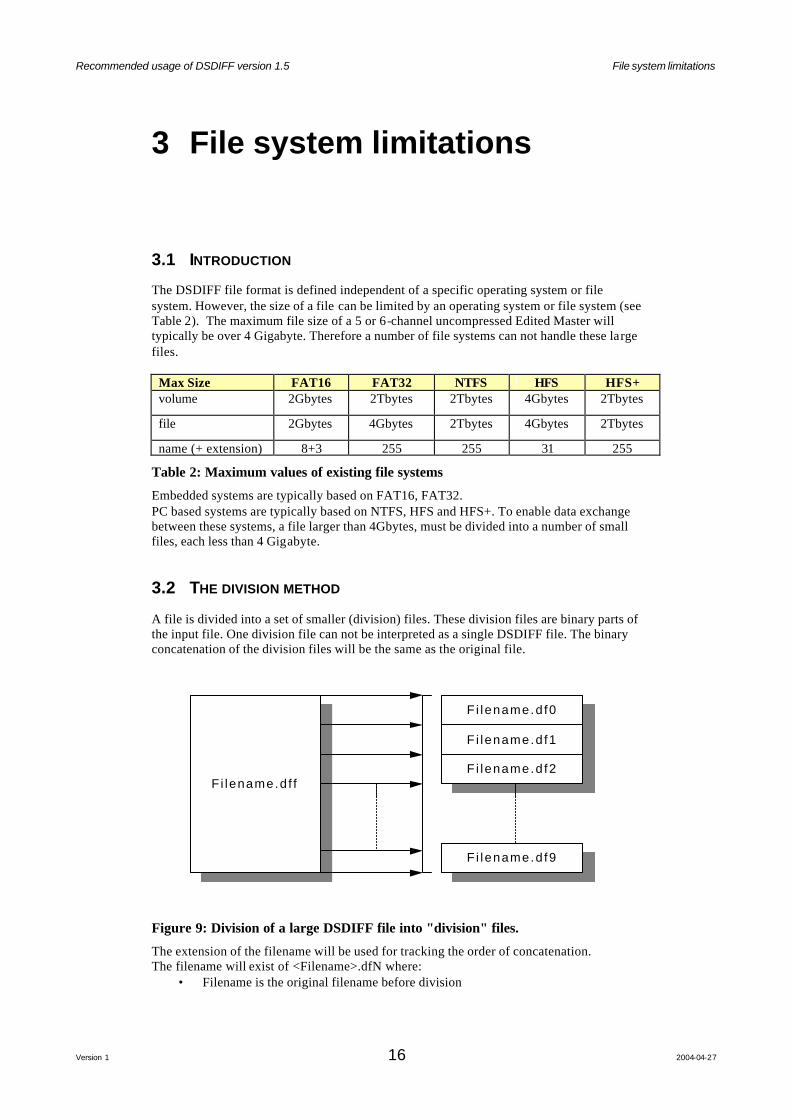
The DSDIFF file format is defined independent of a specific operating system or file system. However, the size of a file can be limited by an operating system or file system (see Table 2). The maximum file size of a 5 or 6-channel uncompressed Edited Master will typically be over 4 Gigabyte. Therefore a number of file systems can not handle these large files.
Max Size FAT16 FAT32 NTFS HFS HFS+ volume 2Gbytes 2Tbytes 2Tbytes 4Gbytes 2Tbytes
file 2Gbytes 4Gbytes 2Tbytes 4Gbytes 2Tbytes
name (+ extension) 8+3 255 255 31 255
Table 2: Maximum values of existing file systems
Embedded systems are typically based on FAT16, FAT32. PC based systems are typically based on NTFS, HFS and HFS+. To enable data exchange between these systems, a file larger than 4Gbytes, must be divided into a number of small files, each less than 4 Gigabyte.
3.2 THE DIVISION METHOD
A file is divided into a set of smaller (division) files. These division files are binary parts of the input file. One division file can not be interpreted as a single DSDIFF file. The binary concatenation of the division files will be the same as the original file.
2
Tra
ckS
tart
Dis
cSta
rt
1
Fi lename.d f fF i lename.d f f
F i lename.d f0F i lename.d f0
F i lename.d f1F i lename.d f1
F i lename.d f2F i lename.d f2
F i lename.d f9F i lename.d f9
Figure 9: Division of a large DSDIFF file into "division" files.
The extension of the filename will be used for tracking the order of concatenation. The filename will exist of <Filename>.dfN where:
• Filename is the original filename before division
Recommended usage of DSDIFF version 1.5 File system limitations
Version 1 17 2004-04-27
• N denotes the order of the division files: the extensions of the divided files [df0 ...df9] represent the order of concatenation.
A DSDIFF file can be divided into a maximu m of 10 division files.
Recommended usage of DSDIFF version 1.5 Time File
Version 1 18 2004-04-27
4 Time File
4.1 INTRODUCTION
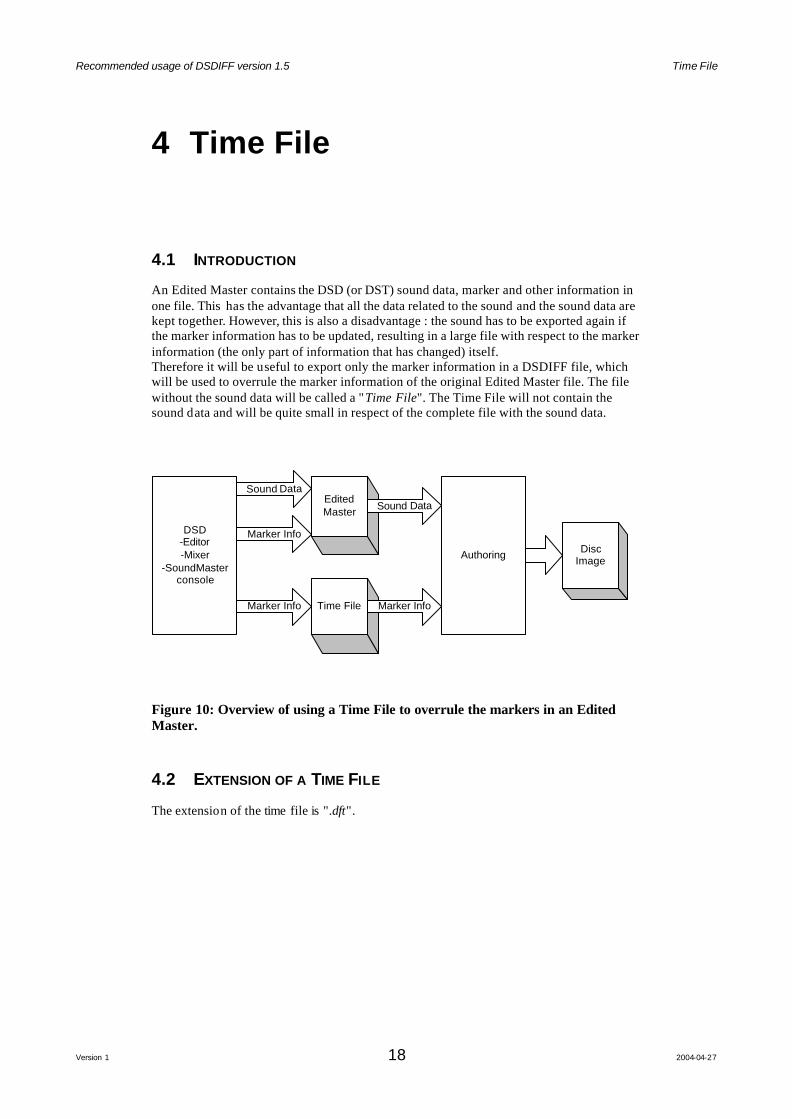
An Edited Master contains the DSD (or DST) sound data, marker and other information in one file. This has the advantage that all the data related to the sound and the sound data are kept together. However, this is also a disadvantage : the sound has to be exported again if the marker information has to be updated, resulting in a large file with respect to the marker information (the only part of information that has changed) itself. Therefore it will be useful to export only the marker information in a DSDIFF file, which will be used to overrule the marker information of the original Edited Master file. The file without the sound data will be called a "Time File". The Time File will not contain the sound data and will be quite small in respect of the complete file with the sound data.
Authoring DiscImage
EditedMaster
Time File Marker Info
DSD-Editor-Mixer
-SoundMasterconsole
Sound Data
Marker Info
Marker Info
Sound Data
Figure 10: Overview of using a Time File to overrule the markers in an Edited Master.
4.2 EXTENSION OF A TIME FILE
The extension of the time file is ".dft".
Recommended usage of DSDIFF version 1.5 Time File
Version 1 19 2004-04-27
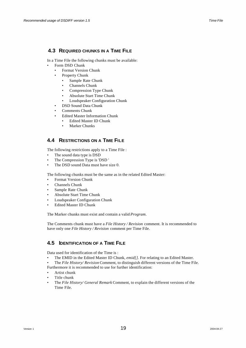
4.3 REQUIRED CHUNKS IN A TIME FILE
In a Time File the following chunks must be available: • Form DSD Chunk
• Format Version Chunk • Property Chunk
• Sample Rate Chunk • Channels Chunk • Compression Type Chunk • Absolute Start Time Chunk • Loudspeaker Configuration Chunk
• DSD Sound Data Chunk • Comments Chunk • Edited Master Information Chunk
• Edited Master ID Chunk • Marker Chunks
4.4 RESTRICTIONS ON A TIME FILE
The following restrictions apply to a Time File : • The sound data type is DSD • The Compression Type is 'DSD ' • The DSD sound Data must have size 0. The following chunks must be the same as in the related Edited Master: • Format Version Chunk • Channels Chunk • Sample Rate Chunk • Absolute Start Time Chunk • Loudspeaker Configuration Chunk • Edited Master ID Chunk The Marker chunks must exist and contain a valid Program. The Comments chunk must have a File History / Revision comment. It is recommended to have only one File History / Revision comment per Time File.
4.5 IDENTIFICATION OF A TIME FILE
Data used for identification of the Time is : • The EMID in the Edited Master ID Chunk, emid[]. For relating to an Edited Master. • The File History/ Revision Comment, to distinguish different versions of the Time File. Furthermore it is recommended to use for further identification: • Artist chunk • Title chunk • The File History/ General Remark Comment, to explain the different versions of the
Time File.
Recommended usage of DSDIFF version 1.5 File History
Version 1 20 2004-04-27
5 File History
5.1 INTRODUCTION
The Comments Chunks in DSDIFF can store different kinds of comments. One of the Comment types is the File History. The File History type has subsets, called references. By looking at all the comments designated by a File History reference a change history of the file can be made up. Specified references are : • General Remark
A remark why and how a specific operation has been performed. • Operator
The name or User Identification of the operator. • Creating Machine
The name and version of the machine or application responsible for creating the file. • Place or Zone
The information about the time zone (or location) with respect to GMT. • Revision
The revision number of the Time File. General Recommendation: When the sound data of a DSDIFF file is copied to another file it is good practice to copy all comments (in the same order) to keep the history of the file. The time stamp is leading for the order of the comments. But there will be applications writing DSDIFF files without a real time clock. These applications should specify a year less than 2000, indicating that there is no real-time clock available. Linking comments by means of using the same time stamp will also apply here. So the first set of comments generated should use the year 0, the second set year 1, etc. When time stamps less than 2000 exist then order of the comments in the DSDIFF file will be leading over the time stamp.
5.2 FILE REVISION INFORMATION
When an error in the Edited Master is noticed a new Edited Master has to be generated incorporating the fix. By generating another Edited Master or a Time File one should distinguish the different file versions.
5.2.1 Edited Masters
To distinguish the different versions of an Edited Master one should: • Create a new EMID when the audio data is changed. • Add or increase the File History / Revision number when metadata is changed, but
the audio data remain unchanged. The textual description of the reason of the remake should be added as a File History / General Remark . It is recommended to use the File History / Revision in an Edited Master when metadata is changed, while the audio data remained unchanged. An EMID can exist of: <company><project><date><time>
Recommended usage of DSDIFF version 1.5 File History
Version 1 21 2004-04-27
Example of an EMID: "Philips_SuperAudioCDProject_2004-03-22_17:00"
5.2.2 Time Files
To distinguish the different versions of a Time File one can: • Add or increase the File History / Revision number
The textual description of the change/remake should be added as a File History / General Remark. The relation between a Time File and an Edited Master is maintained by the EMID.
5.2.3 Relation between Edited Master and Time Files
Edited MasterEMID : EM1
Rev : -
Time FileEMID : EM1
Rev : (1)
A
BUpdate of Timinginformation
(Textual description of the changeis added and other information in
the chunks is copied)
Timing original Timing (1)
no Audio Data
Timing Information
Audio DataAuthoring
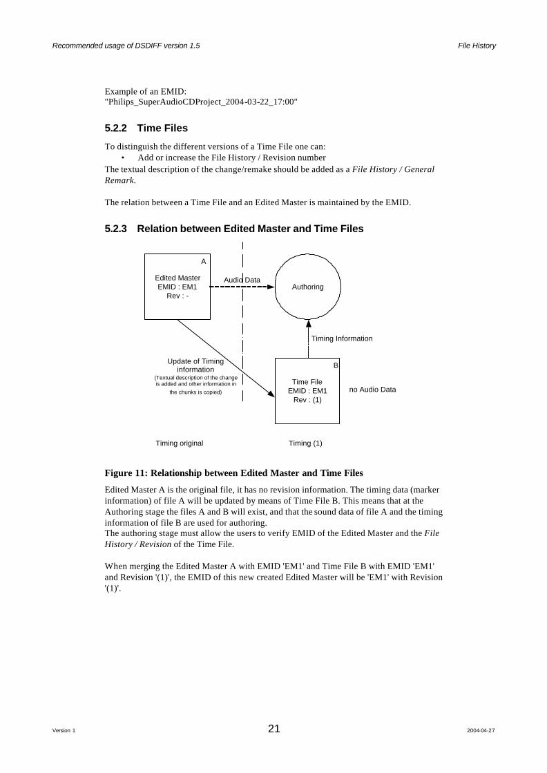
Figure 11: Relationship between Edited Master and Time Files
Edited Master A is the original file, it has no revision information. The timing data (marker information) of file A will be updated by means of Time File B. This means that at the Authoring stage the files A and B will exist, and that the sound data of file A and the timing information of file B are used for authoring. The authoring stage must allow the users to verify EMID of the Edited Master and the File History / Revision of the Time File. When merging the Edited Master A with EMID 'EM1' and Time File B with EMID 'EM1' and Revision '(1)', the EMID of this new created Edited Master will be 'EM1' with Revision '(1)'.
Recommended usage of DSDIFF version 1.5 File History
Version 1 22 2004-04-27
Time FileEMID : EM1
Rev : (1)
Edited MasterEMID : EM1
Rev : -
All Data except Audio Data(Chunks, Time Information)
Edited MasterEMID : EM1
Rev : (1)
Audio Data
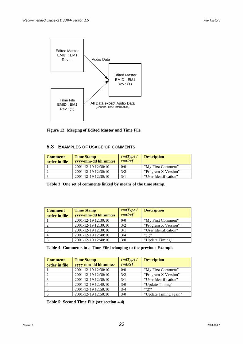
Figure 12: Merging of Edited Master and Time File
5.3 EXAMPLES OF USAGE OF COMMENTS
Comment order in file
Time Stamp yyyy-mm-dd hh:mm:ss
cmtType / cmtRef
Description
1 2001-12-19 12:30:10 0/0 "My First Comment" 2 2001-12-19 12:30:10 3/2 "Program X Version" 3 2001-12-19 12:30:10 3/1 "User Identification"
Table 3: One set of comments linked by means of the time stamp.
Comment order in file
Time Stamp yyyy-mm-dd hh:mm:ss
cmtType / cmtRef
Description
1 2001-12-19 12:30:10 0/0 "My First Comment" 2 2001-12-19 12:30:10 3/2 "Program X Version" 3 2001-12-19 12:30:10 3/1 "User Identification" 4 2001-12-19 12:40:10 3/4 "(1)" 5 2001-12-19 12:40:10 3/0 "Update Timing"
Table 4: Comments in a Time File belonging to the previous Example.
Comment order in file
Time Stamp yyyy-mm-dd hh:mm:ss
cmtType / cmtRef
Description
1 2001-12-19 12:30:10 0/0 "My First Comment" 2 2001-12-19 12:30:10 3/2 "Program X Version" 3 2001-12-19 12:30:10 3/1 "User Identification" 4 2001-12-19 12:40:10 3/0 "Update Timing" 5 2001-12-19 12:50:10 3/4 "(2)" 6 2001-12-19 12:50:10 3/0 "Update Timing again"
Table 5: Second Time File (see section 4.4)
Recommended usage of DSDIFF version 1.5 File History
Version 1 23 2004-04-27
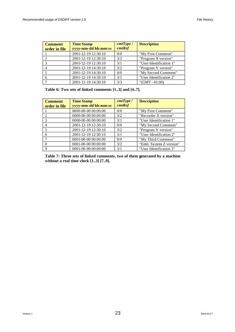
Comment order in file
Time Stamp yyyy-mm-dd hh:mm:ss
cmtType / cmtRef
Description
1 2001-12-19 12:30:10 0/0 "My First Comment" 2 2001-12-19 12:30:10 3/2 "Program X version" 3 2001-12-19 12:30:10 3/1 "User Identification 1" 4 2001-12-19 14:30:10 3/2 "Program Y version" 5 2001-12-19 14:30:10 0/0 "My Second Comment" 6 2001-12-19 14:30:10 3/1 "User Identification 2" 7 2001-12-19 14:30:10 3/3 "(GMT –01:00)
Table 6: Two sets of linked comments [1..3] and [4..7].
Comment order in file
Time Stamp yyyy-mm-dd hh:mm:ss
cmtType / cmtRef
Description
1 0000-00-00 00:00:00 0/0 "My First Comment" 2 0000-00-00 00:00:00 3/2 "Recorder X version" 3 0000-00-00 00:00:00 3/1 "User Identification 1" 4 2001-12-19 12:30:10 0/0 "My Second Comment" 5 2001-12-19 12:30:10 3/2 "Program Y version" 6 2001-12-19 12:30:10 3/1 "User Identification 2" 7 0001-00-00 00:00:00 0/0 "My Third Comment" 8 0001-00-00 00:00:00 3/2 "Emb. System Z version" 9 0001-00-00 00:00:00 3/1 "User Identification 3"
Table 7: Three sets of linked comments, two of them generated by a machine without a real time clock [1..3] [7..9].

Recommended usage of DSDIFF version 1.5 Appendix A : The CRC algorithm
Version 1 24 2004-04-27
APPENDIX A : THE CRC ALGORITHM Source code for calculating the CRC over the DSD data of size of 1 DST frame. #define CRC_CRCSize (4) // Size of the CRC in bytes #define CRC_FRAMESIZEONECHANNEL (4704) // FrameSize in bytes of one channel ULONG CRC_CalcOverDSD(int numChannels,BYTE* Message,bool Check) { // numChannels : the amount of input channels [2,5,6], this determines the length of the input message. // Message : the actual DSD stream with length of 1 Frame. // Check : TRUE, checking the CRC, message is appended with the CRC to be checked // FALSE : calculating the CRC, returned in a ULONG. ULONG Poly = 0x40000008; // polynomial, shifted 1 bit to the right const unsigned long Long_msb = 0x80000000; // used to check value of bit 31 of shift register const unsigned long Short_msb = 0x80; // used to check value of bit 7 of messagebyte int MessageByte; // used to store 1 messagebyte int i,j; // counters long unsigned Rem; // used to store contents of shift register (remainder) int numBytes = CRC_FRAMESIZEONECHANNEL*numChannels; // amount of bytes in the message if (Check) numBytes +=CRC_CRCSize; // increase with the size of the polynom // // Dat a is put through a 32 bits shift register. After all data has been processed, the // shiftregister contains the CRC value (this is called the remainder, variable REM). // When the Check option is on, the 4 CRC bytes are also put through the shift register. // If that CRC is correct, the remainder should be zero at the end. // Data is put through, MSB first. // Shifting is easy: // if bit 31 of the shift register (=Rem) is not equal to the next databit then the value // of the shift register is XOR'ed with the shift polynomial (that polynomial equals // the XOR gates of the shift register, excluding the first and the last gate). The register // is shifted 1 position to the left (a 1 is inserted at bitposition 0). Otherwise // the register is shifted 1 position to the left (a 0 is inserted at bitposition 0). Rem = 0L; // initialize shift register for (i=0;i<(numBytes);i++) // process all bytes { MessageByte = Message[i]; for (j=0;j<8;j++) // process bits of 1 byte { if ( (((MessageByte & Short_msb) == Short_msb)) != (((Rem & Long_msb) == Long_msb))) { Rem ^= Poly; // XOR and shift with value 1 Rem = (Rem << 1) + 1; } else { Rem = (Rem << 1); // no XOR, shift with value 0 } MessageByte <<= 1; // shift byte so next bit of data will be processed }; }; return (Rem); }