recommendatory urban bus specifications ii
TRANSCRIPT

Recommendatory
Urban Bus Specifications – II
Ministry of Urban Development
Government of India
www.moud.gov.in
April, 2013

Ministry of Urban Development
Government of India
www.moud.gov.in
April, 2013
Recommendatory
Urban Bus Specifications – II

Minister of Urban Development
Government of India
dey ukFk
Kamal Nath ea=h
“kgjh fodkl
Hkkjr ljdkj
Urban Bus Specifications - II 104&lh] fuekZ.k Hkou] ubZ fnYyh&110008] Qksu % 23063495] 23061162 QSDl % 23062089
104 – C, Nirman Bhawan, New Delhi – 110108, Ph: 23063495, 23061162, Fax: 23062089
MESSAGE
Urban transport has increasingly played a key role in making rapidly growing cities livable and sustainable. Sensitivity to
local context and scientific evaluation of available alternatives lies at the core of an efficient public transport system. At the same time,
the soft aspects like access to information, experience of journey and customer satisfaction play an important role in attracting and
retaining users to the system. A proactive branding and communications plan adds significantly to the system image.
As we approach the second phase of JnNURM, the Ministry of Urban Development continues to make constant efforts to
push the reforms agenda and delivery of urban infrastructure. One such initiative is to revisit the Urban Bus Specifications (introduced
in JnNURM – I) to help cities procure and run modern city buses. This document – “Urban Bus Specifications – II” lays out standards
for cities to base their choice from a definite set of options for streamlining bus operations. The specifications also include those for buses
for BRTS (Bus Rapid Transit Systems) as more and more cities embrace the concept, underpinning the need for standardization.
The specifications are prepared in consultation with the industry, academia and state transport undertakings. I congratulate
the Urban Bus Committee for successfully creating these standards that are bound to bridge the gap between user expectations and the
bus services.
(Kamal Nath)

Ministry of Urban Development
Nirman Bhawan, New Delhi - 110008
MkW- lqèkhj Ñ".kk
Dr. Sudhir
Krishna
“kgjh fodkl ea=ky;
fuekZ.k Hkou] ubZ fnYyh&110008
lfpOk] Hkkjr ljdkj
Secretary to the Government of India
Urban Bus Specifications - II 104&lh] fuekZ.k Hkou] ubZ fnYyh&110008] Qksu % 23063495] 23061162 QSDl % 23062089
104 – C, Nirman Bhawan, New Delhi – 110108, Ph: 23063495, 23061162, Fax: 23062089
FOREWORD
India’s urban population is going to nearly double by 2030. This comes as a challenge to cities that are already facing acute
shortage of quality urban transport. To ease this situation and move towards creation of sustainable infrastructure, Govt. of India launched
JnNURM in 2005. Acknowledging that urban transport was a key sector that needed significant interventions, the National Urban Transport
Policy (NUTP) was introduced in 2006 to guide the efforts by cities towards sustainable transportation systems and urban development. The
policy very clearly stated that the focus is to promote movement of people over vehicles, and recommended good quality public transport in
medium and large cities.
The current investments in public transport, especially city bus services are far from adequate to meet the emerging demand. The
High Powered Expert Committee on Urban Infrastructure and the MoUD estimated that cities in India need about 1.5 lakh buses amounting to
approximately Rs. 60,000 crores in the next 20 years. The report further cites that only 20 of 85 cities with over 0.5 million population (2009)
offer a organised city bus service. The recommendations of the Working Group on Urban Transport for 12th Five Year Plan include introduction
of organized public transport in all 2 lakh+ population cities and state capitals, as one of its goals. The report asserts that city bus services have
been and will continue to be the major mode of public transport in Indian cities. It was recommended that the buses be procured as per urban
bus specifications and managed by a special purpose vehicle. The service level benchmarks for urban transport also direct that the fleet meets
urban bus specifications.
The Ministry of Urban Development introduced Urban Bus Specifications in 2008 in view of the increased need for funding and
guidance to cities in procurement of city buses. Under the 2nd economic stimulus package of the Government of India, 61 cities procured about
13400 buses under JnNURM and in the process and brought forth some lacunae and gaps in the urban bus specifications.

Urban Bus Specifications - II 104&lh] fuekZ.k Hkou] ubZ fnYyh&110008] Qksu % 23063495] 23061162 QSDl % 23062089
104 – C, Nirman Bhawan, New Delhi – 110108, Ph: 23063495, 23061162, Fax: 23062089
The Ministry of Urban Development reached out to various stakeholders to identify potential issues to be resolved for going
forward and found that cities were operating very different types of buses across the country. These buses were often retrofitted to
accommodate modern technology (IT systems). The development of prototypes as per city’s specifications took a long time, thus delaying
procurement. Most cities did not follow any standardized maintenance manuals and codes of practice. A key learning was that inadequate
detailing of specifications created complexities in tendering process that cities were not prepared for.
In an attempt to address these issues and facilitate the process of bus procurement in anticipation of next round of funding under
JnNURM-2, MoUD constituted an Urban Bus Committee in March, 2012. The committee worked towards revising the existing urban bus
specifications to achieve uniformity in the bus manufacturing industry with minimal variants for a city to choose from. Additional objectives
included consideration for driver and passenger comfort, enhanced safety, universal design, in-built ITS technology etc. The specifications also
incorporate desired standards for reduced pollution and improved fuel efficiency. New variants to attract premier customers and specialised
buses for BRTS have been introduced.
These specifications are applicable to buses for urban operation defined as a vehicle intended for operations within the confines
of a city or a greater metropolitan area. Such operations are associated with frequent stops/starts and the bus for urban bus operations is
designed and constructed accordingly with space for standing passengers. It is intended that the specifications contained in this document will
apply to all urban bus services in the country irrespective of their sources of funding. The anticipated benefits of this publication are:
Attracting choice riders to use public transport including people with disabilities
Better working environment for drivers
Driver training and introducing customer care & complaints redressal system
Focus on R&D to improve product quality to meet stringent safety tests
Bringing efficiencies in the operations and maintenance practices
Leveraging benefits of contractual bidding for procurement process
I encourage all STUs/transport authorities/SPVs/operators and other organizations associated with urban transport to use these standards and to
facilitate comfortable, affordable, safe and reliable public transport system in cities.
Dated: April, 2013 (Dr. Sudhir Krishna)

Ministry of Urban Development
Nirman Bhawan, New Delhi - 110008
Hkkjr ljdkj
“kgjh fodkl ea=ky;
fuekZ.k Hkou] ubZ fnYyh&110008
Urban Bus Specifications - II 104&lh] fuekZ.k Hkou] ubZ fnYyh&110008] Qksu % 23063495] 23061162 QSDl % 23062089
104 – C, Nirman Bhawan, New Delhi – 110108, Ph: 23063495, 23061162, Fax: 23062089
,l- ds- Yk®fg¸kk
S. K. Lohia
OSD (UT), Ex. Officio, JS, MoUD
PREFACE
The National Urban Transport Policy (NUTP), 2006, outlines the need to create and maintain safe, affordable, rapid, comfortable, reliable and
accessible public transport in cities in India. In the discussion of available technologies for achieving sustainable public transport, the policy advocates bus based
systems. However, it was soon realized that the city buses in India suffer from a poor brand image, low on passengers, not ITS enabled and poor on ergonomics.
Taking cognizance of the need to focus on comfort, safety, reliability and efficiency of bus based public transport system in urban areas; Ministry of Urban
Development (MoUD) recommended “Specifications for Urban Buses in 2008 for the first time in India.
While approving the funding for purchase of urban buses for the mission cities under JnNURM, the urban bus specifications were made
mandatory. Consequently, these specifications facilitated the procurement of more than 13400 ITS enabled modern buses across 61 cities in India, thereby
changing the landscape of bus based public transport in the country. Today these specifications have been widely accepted within the industry.
MoUD received invaluable feedback from stakeholders on the urban bus specifications. Some of the key learning were: the need to reduce
number of variants through greater degree of standardization; ITS specifications should be integral to the bus specifications; greater focus on driver as well as
passenger comfort; more detailing of specifications and need for separate specifications for BRT buses as well as premium category buses.
With a view to synthesize the above learning and provide further impetus to a responsive bus based public transport systems in urban areas there
was a need to revise the urban bus specifications. Accordingly, MoUD on March 14, 2012 constituted a Committee to revise the urban bus specifications. The
objectives of the Committee for revision of the urban bus specifications were:
Focus on the comfort and ride quality for passengers and drivers
Enhanced safety features including accessible for persons with disability
Standardisation of bus features
Adoption of cutting edge technology integrated with ITS
Reduction in bus feature variants
Improved fuel efficiency
Separate specifications for buses for BRT operations
Introduction of new variants- premium, articulated and bi-articulated buses

Urban Bus Specifications - II 104&lh] fuekZ.k Hkou] ubZ fnYyh&110008] Qksu % 23063495] 23061162 QSDl % 23062089
104 – C, Nirman Bhawan, New Delhi – 110108, Ph: 23063495, 23061162, Fax: 23062089
Special emphasis has been given to the safety of the women passengers while deciding the specifications. Features like wider windows, lighting, CCTV cameras,
inner signage displaying helpline number, ‘foot operated micro pedal switch for emergency’ to communicate to control room, two way communication of driver
with control room and automatic vehicle location system (AVL) have been added as part of UBS-II. Moreover, features like ‘manual ramp’ & ‘exclusive space’
for wheel chair, ‘buzzer for stop request’ will make these buses more accessible for passengers with disability.
The Committee comprised members from (i) M/o Road Transport & Highways, (ii) D/o Heavy Industries, (iii) Delhi Transport Corporation (DTC), (iv) Bureau of
Police Research and Development (BPR&D), (v) Bangalore Metropolitan Transport Corporation (BMTC), (vi) Society of Indian Automobile Manufacturers
(SIAM), (vii) Association of State Road Transport Undertakings (ASTRU), (viii) Indian Association of Bus Manufacturers (IABM), (ix) Automotive Research
Association of India (ARAI), (x) Central Institute of Road Transport (CIRT), (xi) Institute of Urban Transport (IUT) (xii) Urban Mass Transit Company (UMTC)
and (xiii) Centre of Excellence CEPT, Ahmedabad. The Committee also set up Core Group to assist the Committee in researching and drafting the specifications
in consultation with industry experts, bus manufacturers, vendors, suppliers etc.
The Committee, cognizant of the lead time, required to implement advancements in bus technology and the related development costs has
prepared a road map for upgrading of specifications. The revised urban bus specifications have identified certain technology advancements which will come into
effect from April 1, 2015. The advantage of such a road map is that it obviates the need for frequent revision of the standards and specifications and helps bus
manufacturers to focus their R&D activities in a pre-charted direction.
National level stakeholders consultations on the draft revised specifications were held on 7th September, 2012 at Ahmedabad and on 1st October,
2012 at New Delhi and after considering the suggestions, feedback and inputs from various stakeholders the Committee has finalized the Urban Bus
Specifications II.
This exercise is a collective work of representatives from various Ministries, Automobile Industry, ITS Manufacturers, Research Institutes,
Associations and Experts. I sincerely thank all the members of “Urban Bus Committee” and “Core Group”, especially Mr. Ajai Mathur & Mr. Laghu Parashar
from UMTC Ltd, Prof. Shivanand Swamy & Prof. Manjiri Akalkotkar from CoE, CEPT University and Mr. A.S. Lakra, former Director, CIRT, Pune for their in-
depth involvement throughout this exercise. I am also thankful to officials from various State Governments for giving their valuable suggestions during
stakeholders workshops. I am grateful for the support and guidance received from Dr. Sudhir Krishna, Secretary, Ministry of Urban Development, Government of
India who has also been instrumental in supporting at all steps. I am also grateful to Shri Kamal Nath, Hon’ble Minister for Urban Development for providing the
vision and leadership in changing the face of urban transport in India. I strongly believe that these specifications for urban buses will give a fillip to our endeavor
to transform the urban transport scenario in the country so that public transport can be marketed as a ‘Branded product’ and public transport becomes a preferred
and safe mode of transport for all.
Dated: April, 2013 (S. K. Lohia)

Table of Content Abbreviations……………………………………………………………………………………………………....................... (i)
Chapter 01 – Scope, purpose and definitions…………………………………………………………………....................... 01
Chapter 02 – Specifications for standard size bus……………………………………………………………....................... 03
Chapter 03 – Specifications for mini and midi bus………………………………………………………………………….. 18
Chapter 04 – Specifications for standard size BRT bus……………………………………………………………………... 37
Chapter 05 – Specifications for mini and midi BRT bus……………………………………………………………………. 54
Chapter 06 – Specifications for standard size bus of premium segment……………………………………..................... 72
Chapter 07 – Specifications for midi bus of premium segment…………………………………………………………….. 96
Chapter 08 – Specifications for articulated bus for guidance………………………………………………………………. 118
Chapter 09 – Specifications for Bi-articulated bus for guidance…………………………………………………………… 139
Chapter 10 – Specifications for Intelligent Transport Systems (I.T.S.)…………………………………………………….. 161
Annexure 1 – Windshield designs
Annexure 2 – Figures
Annexure 3 – Design Type Approval
Annexure 4 – Test procedure for evaluation of AC system performance
Annexure 5 – List of participants of “Urban Bus Committee”

Abbreviations (Used in Bus Specifications)
ABS Acrylonitrile Butedienestyrene
ABS Anti skid anti brake locking system
A.C. Air Conditioned
ACX Air Conditioned Deluxe
AIS Automotive Industry Standards
AIS052 Code of Practice for Bus Body Design and Approval (Revision 1): 2008
ASTM American Standard for Testing of Materials
BIS Bureau of Indian Standards
BRTS Bus Rapid Transit System
BS Bharat Stage
C/L Centre Line
CCTV Closed Circuit Television
CLC Cabin Luggage Carrier
CMVR Central Motor Vehicle Rules
CNG Compressed Natural Gas
dbA Decibels on scale A
DC Direct Current
DIN German Standards
EBS Electronic Braking control System
ECAS Electronically Controlled Air Suspension
ELR Emergency Locking Retractors
EMS Electronic Engine Management System
ERW Electric Resistance Welding
g gram
gms/cc grams per cubic centimetre
GSR General Statutory Rules
GVW Gross Vehicle Weight
HP Horse Power
Ht. Height
Hz Hertz
ICE Internal Combustion Engine
IS Indian Standards
ISO International Organization for Standardization
ITS Intelligent Transport System
JASO Japanese Automotive Standards Organization
Kg/m3 kilogram per cubic metre
Kg Kilogram
Km Kilometers
Kmph Kilometres per hour
Kmpkg Kilometre per kilogram
Kmpl kilometre per litre
LDPE Low Density Poly-ethylene
lux unit of illumination
m/s metre per second
MDI Methylene Diphenyl Di-isocyanate
mm millimetre
NBS National Bureau of Standards
NDX Non Deluxe
NVH Noise Vibration and Harshness
oC degree Celsius
pax Passenger
PPLD Poly Propylene Low Density

PU Poly Urethane
PVB Polyvinyl butyryal
PVC Poly Vinyl Chloride
PwD People with Disability
RE bus Rear Engine bus
RMS Root Mean Square
rpm Revolutions per Minute
SAE Society of Automotive Engineers
SPV Special Purpose Vehicle
Sq.mm Square millimetre
STU State Transport Undertaking
ULSD Ultra-Low-Sulphur diesel
VM Vehicle Manufacturer
2G Second Generation
3G Third Generations
AIS Automotive Industry Standard
AMPS Advanced Mobile Phone System
API Application Programming Interface
ARAI Automotive Research Association of India
AV Audio-Video
AVI Audio Video Interleave
AVL Automatic Vehicle location System
BDC Bus Driver Console
BIS Bureau of Indian Standards
Bit Binary digit
BRTS Bus Rapid Transit System
CAN Controller Area Network.
CCC Central Control Centre
CCD Charge Coupled Device
CIRT Central Institute for Road Transport
CMVR Central Motor Vehicles Rules
COP Conformity of Production
CPU Central Processing Unit
dBm Power ratio in decibels
DC Direct Current
DCS Digital Cellular Service
oC degree Celsius
DTC Diagnostic Trouble Code
DVI Digital Visual Interface
DVR Digital Video Recording
EEPROM Electrically Erasable Programmable Read-Only Memory
EMC Electro Magnetic Compatibility
FME (F) For Mobile Equipment Female
FPS Frames per Second
GB Giga Byte
GPGGA Global Positioning System Fix Data
GPGSA Global Positioning Overall Satellite data
GPGSV Global Positioning Satellites in view
GPIO General Purpose Input Output
GPRMC Global Positioning Recommended Minimum Data
GPRS General Packet Radio Service
GPS Global Positioning System
GPVTG Global Positioning Vector track and Speed over the Ground
GSM Global System for Mobile Communications
HDMI High-Definition Multimedia Interface
Hz Hertz
IEC International Electro technical Commission
IEEE The Institute of Electrical and Electronics Engineers
Abbreviations (Used in I.T.S. Specifications)

IP Ingress Protection
IP Internet Protocol
IR Infra Red
ISI Indian Standards Institute
ISM Industrial Scientific and Medical
ISO International Organization for Standardization
ITS Intelligent Transport System
Kb Kilobit
LAN Local Area Network
LAT Latitude
LCD Liquid Crystal Display
LED Light Emitting Diode
LONG Longitude
ma Milliamps
MB Mega Byte
mCd milli Candela
MoUD Ministry of Urban Development
NAT Network Address Translation
NDA Non-Disclosure Agreement
nm Newton Meter
NMEA National Marine Electronics Association
OBITS On Bus Intelligent Transport System
OEM Original Equipment Manufacturer
PA Public Announcement System
PAL Phase Alternating Line
PCB Printed Circuit Board
PCS Personal Communications Service
PGN Parameter Group Number
PID Parameter Identifier
PIS Passenger Information System
PLCC Plastic Leaded Chip Carrier
PWD Person with Disability
PWM Pulse Width Modulation
RAM Random Access Memory
RHCP Right Hand Circular Polarization
RMS Root Mean Square
RPM Revolutions Per Minute
SCN Security Camera Network System
SCU Single Control Unit
SMA (M) ST Sub Miniature version A Male Straight
SMT Surface Mount Technology
SPN Standardized Message name,
TA Type Approval
TCP/IP Transmission Control Protocol/Internet Protocol
TCP Transmission Control Protocol
TFT Thin film transistor
Typ Typical
UBS Urban Bus Specification
UMTS Universal Mobile Telecommunications System
UV Ultraviolet
VGA Video Graphics Array
VHMD Vehicle Health Monitoring and Diagnostics
VSWR Voltage Standing Wave Ratio
WLAN Wireless Local Area Network
XML Extensible Markup Language
SD Secure Digital
Abbreviations (Used in I.T.S. Specifications)

Scope, Purpose and Definitions
Chapter - 01
Scope, Purpose and Definitions
Urban Bus Specifications – II, Ministry of Urban Development, Government of India 1
Scope & Purpose
With introduction of the National Urban Transport Policy (NUTP) in April 2006, the Government of India endorsed the idea that it’s essential
for the country to work towards building of sustainable transport infrastructure. The policy outlines the need to create and maintain safe,
affordable, rapid, comfortable, reliable and accessible public transport in cities in India. In the discussion of available technologies for achieving
sustainable public transport, the policy promulgates bus based systems. It was also realized that the bus based public transport systems are
operating in various arrangements in different cities and lack any kind of standardization.
The Ministry of Urban Development (MOUD) recognized the need and introduced specifications for urban buses in 2008. Based on this
experience, the Ministry took feedback from various stakeholders and formulated an ‘Urban Bus Committee” in March 2012 to address these
issues. The committee revised urban bus specifications to achieve uniformity in the bus manufacturing industry with minimal variants.
The Ministry of Urban Development, Government of India hereby formulates the following specifications and standards that have to be
complied with by the relevant category of buses used in urban bus services:
1. Standard bus -(A/C and Non AC)
2. Mini bus-(A/C and Non AC)
3. Midi bus -(A/C and Non AC)
4. Premium Standard Bus Segment –A/C
5. Premium Midi Bus Segment –A/C
6. Bus Rapid Transit System
a. 12 m standard BRT bus
b. 18 m articulation BRT bus for guidance only
c. 24 m Bi-articulated BRT bus for guidance only
d. Mini Bus
e. Midi Bus
7. Intelligent Transport System (I.T.S)

Scope, Purpose and Definitions
Urban Bus Specifications – II, Ministry of Urban Development, Government of India 2
These specifications are applicable to the buses for urban operation means “a vehicle intended for operations within the confines of a city or a
greater metropolitan area. Such operations are associated with frequent stops/starts and the bus for urban bus operations is designed and
constructed accordingly with space for standing passengers".
This document aims to enhance the attractiveness of buses used to provide urban services in order to encourage increased usage, with a
particular emphasis on improving accessibility for all users, including people with physical, sensory and cognitive impairments.
Definitions
Unless otherwise specified, definitions of terms used in this document shall be as per AIS-052, Code of Practice for Bus Body Design and
Approval or The Central Motor Vehicles Rules (CMVR), 1989, as applicable.

Chapter - 02
Specifications for Standard size bus

Specifications for Standard Bus
Urban Bus Specifications – II, Ministry of Urban Development, Government of India 3
Bus specifications of standard size urban bus (AC/Non-AC)
S. No. Description Specifications
Bus characteristics Maximum floor height: 400/650/9001 mm
Definition of Low Floor area
Low floor area shall not be less than 50% of the total saloon area
(excluding front wheel boxes and driver’s cab) and shall not be ramped
in the longitudinal plane
1 Propulsion system ICE, electrical, hybrid, fuel cell
2 Fuel-options Fuel to be compatible with propulsion system & prescribed emission
norms
3 Engine
3.1 Engine HP sufficient to provide:
a Rated performance at GVW in a stop/start urban operations Geared maximum speed without speed limiter to be 75 kmph
b Acceleration (metre/sec²) ≥ 0.8
c Attain bus speed of 0-30 kmph in seconds ≤ 10.5
d Maximum speed Geared maximum speed without speed limiter to be 75 kmph
e Grade ability from stop at GVW 17%
f Rated HP/torque preferably at lower rpm range Maximum engine torque required at lower range of RPM and spread
over a wider range of RPM
g Power requirements for Air conditioning system, ITS etc Required
3.2 Emission norms BS III/BS IV or latest as applicable
3.3 Engine management Engine oil pressure, engine coolant temperature, engine speed in RPM,
vehicle speed, diagnostic details message (engine specific)
3.4 Engine operational requirements
Engine should be able to operate efficiently at ambient temperatures of
approximately 0° to 50° C, humidity level from 5% to 100%, and
altitude levels of up to 2000 meters, generally operating in the semi arid
zone/hilly region prevailing in the area.
1 Cities having population ≤ 1 million (as per census 2011) can procure buses having 900 mm floor height also whereas cities having population more than 1 million (as per
census 2011) will procure either 650mm or 400mm floor height buses. Any change in composition is subject to approval of Ministry of Urban Development (MOUD), GOI. W.E.F. 1.4.2016, 900mm floor height standard size buses are to be procured only as an exception in all cities ≤ 1 million populations also.

Specifications for Standard Bus
Urban Bus Specifications – II, Ministry of Urban Development, Government of India 4
Bus specifications of standard size urban bus (AC/Non-AC)
S. No. Description Specifications
Bus characteristics Maximum floor height: 400/650/9001 mm
3.5 Engine location Optional
3.6 Transmission Purchaser to select any one transmission system. However, rear engine
buses to have either automatic or automated manual transmission system
only. (any bus delivered after 1st April, 2015 will mandatorily have
either automatic or automated manual transmission system)
a Automatic with torque convertor. Neutral during stops
b Automated manual
c Manual - synchromesh - forward speeds (minimum 5) &
constant mesh on reverse gear
4 Operational safety
Transmission system to be fitted with a mechanism which makes it
possible to engage reverse gear only when vehicle is stationary
(applicable for automatic & automatic manual transmission)
5 Clutch (where applicable) Dry, single plate, power assisted operation
5.1 Rear axle Single reduction, hypoid gears, full floating axle shafts with optimal
gear ratios suitable for urban operations
5.2 Front axle Heavy duty reverse Elliot type axle suitable for various floor heights
6 Steering system Hydraulic power steering with height and angle adjustment
7 Suspension system2 Pneumatic
7.1 Front Air bellows - 2 numbers
7.2 Rear Air bellows – 2/4 numbers
7.3 Kneeling applicable in case of air suspension
(required only for 400 mm floor height buses) 60 mm entry/exit side severally & collectively
7.4 Anti roll bars/stabilizers3 Both front and rear
7.5 Shock absorbers Hydraulic double acting 2 at front & 2/4 at rear
2 Only in case of 900 mm floor height buses, front suspension can have option of air suspension/independent/parabolic/weveller type. Irrespective of the type of
suspension, floor level of bus should not go beyond maximum floor height. Any bus delivered after 1st April, 2015 will mandatorily have air suspension or superior in both front & rear. 3 Optional in case of independent suspension

Specifications for Standard Bus
Urban Bus Specifications – II, Ministry of Urban Development, Government of India 5
Bus specifications of standard size urban bus (AC/Non-AC)
S. No. Description Specifications
Bus characteristics Maximum floor height: 400/650/9001 mm
7.6 Controls (optional) Electronically controlled air suspension system
8 Braking system
Dual circuit full air brakes, with preferably disc type arrangement for
front and drum at rear brakes. Graduated hand controlled, spring
actuated parking brakes acting on rear wheels (any bus delivered after
1st April, 2015 will mandatorily have disc brake in front)
8.1 Anti skid anti brake locking system (ABS) As per CMVR
8.2 Electronic controls Optional
9 Electrical system 24 volt DC
9.1 Batteries:
Low maintenance type lead acid batteries for 24 V system- performance
as per BIS:14257-1995 (latest). 2*12V of commensurate capacity.
Maintenance free batteries preferred.
9.2 Self starter 24V
9.3 Alternator 24V (another alternator of similar capacity for AC buses)
9.4 Electrical wiring & controls- type As specified separately under ITS specifications
10 Speed limiting device (optional): Electronic type duly approved /certified as per AIS – 018/2001 or latest,
tamper proof and be adjusted to applicable speed limit
11 Tyres Steel radial tube-less. Size and performance as per CMVR
12 Fuel tank Capable to enable bus operation ≥ 300 km between consecutive fillings
Fuel tank location Optional
13 Bus characteristics
13.1 Bus dimensions (mm)
a Overall length (over body excluding bumper) 12000 (minus tolerance of 100)
b Overall width (sole bar/floor level- extreme points) 2600 (maximum)
c Overall height (unladen - at extreme point) 3800 (maximum)
d Wheel-base 6100 (tolerance -200 +400)

Specifications for Standard Bus
Urban Bus Specifications – II, Ministry of Urban Development, Government of India 6
Bus specifications of standard size urban bus (AC/Non-AC)
S. No. Description Specifications
Bus characteristics Maximum floor height: 400/650/9001 mm
i Front overhang As per CMVR
ii Rear overhang As per CMVR
13.2 Maximum turning circle radius (mm) As per CMVR
13.3 Floor height above ground (mm)- maximum 400/650/900
13.4 Clearances (mm)
a Minimum axle clearance (mm) 190
b Wheel area clearance (mm) > 220 for parts fixed to bus body & > 170 for the parts moving vertically
with axle.
c Minimum ground clearance (un-kneeled) in mm at GVW Within the wheelbase not less than 240
13.5 Angles (degrees)
a Angle of approach (unladen) Not less than 8.5°
b Angle of departure (unladen) Not less than 9.0°
c Ramp over angle (half of break-over angle) Not less than 4.8°
14 Bus gates/Doors
14.1 Type of doors Preferably in-swing in front with option of jack knife and double jack
knife in rear door
a Operating mechanism Electro pneumatically controlled
b Opening/Closing time in seconds per operation (maximum) 4
c Positions of door controls On dashboard and also inside & outside of doors
d Passenger safety system - allowing bus motion on doors
closing and doors opening only when the bus is stopped Mandatory
14.2 Front service doors - (near side/non-driver side) √
a Minimum door aperture (without flaps) in mm 800
b Minimum clear door width (fully opened) in m 650 ± 50
Specifications for Standard Bus
Urban Bus Specifications – II, Ministry of Urban Development, Government of India 7
Bus specifications of standard size urban bus (AC/Non-AC)
S. No. Description Specifications
Bus characteristics Maximum floor height: 400/650/9001 mm
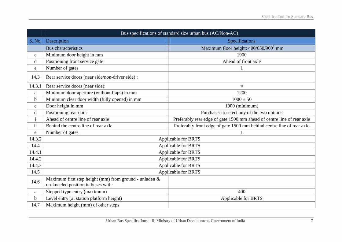
c Minimum door height in mm 1900
d Positioning front service gate Ahead of front axle
e Number of gates 1
14.3 Rear service doors (near side/non-driver side) :
14.3.1 Rear service doors (near side): √
a Minimum door aperture (without flaps) in mm 1200
b Minimum clear door width (fully opened) in mm 1000 ± 50
c Door height in mm 1900 (minimum)
d Positioning rear door Purchaser to select any of the two options
i Ahead of centre line of rear axle Preferably rear edge of gate 1500 mm ahead of centre line of rear axle
ii Behind the centre line of rear axle Preferably front edge of gate 1500 mm behind centre line of rear axle
e Number of gates 1
14.3.2 Applicable for BRTS
14.4 Applicable for BRTS
14.4.1 Applicable for BRTS
14.4.2 Applicable for BRTS
14.4.3 Applicable for BRTS
14.5 Applicable for BRTS
14.6 Maximum first step height (mm) from ground - unladen &
un-kneeled position in buses with:
a Stepped type entry (maximum) 400
b Level entry (at station platform height) Applicable for BRTS
14.7 Maximum height (mm) of other steps

Specifications for Standard Bus
Urban Bus Specifications – II, Ministry of Urban Development, Government of India 8
Bus specifications of standard size urban bus (AC/Non-AC)
S. No. Description Specifications
Bus characteristics Maximum floor height: 400/650/9001 mm
a if door ahead of rear axle 250 (applicable only for 900/650 mm floor ht. buses)
b if door behind rear axle 300 (applicable only for 900/650 mm floor ht. buses)
14.8 Ramp for wheel chair at the gates wherever required
Sunken type wrap over (manually operated) ramp, for wheel chair of
PwDs, fitted on floor at gate in front of PwD seat anchorage. Suitable
design mechanism for 650/900mm floor height considering that floor
level of bus stops are at 400mm
a Dimensions Minimum width 900 mm
b Material Aluminium alloy with anti-slip coating
c Load carrying capacity (in kilograms) > 300
d Device to prevent the wheel chair roll off the sides when the
length exceeds 1200 mm √
e Device to lock wrapped up ramp √
f Kneel ramp control: (applicable in reference of clause 7.3) Kneeling arrangement for kneeling on left side severally and combined.
Kneeling up to 60mm
g Requirement for passengers with limited mobility √
i Wheel chair anchoring - minimum for one wheel chair √
ii Priority seats - minimum 2 seats √
iii Stop request √
h Emergency doors/exits or apertures (Numbers) As per AIS 052
Dimensions in mm As per AIS 052
i Door closing requirements for bus movement - Bus could move only after door closing completed
i
Power operated service door - construction & control system
of a power operated service door to be such that a Passenger
is unlikely to be injured/trapped between the doors while
As per AIS 052

Specifications for Standard Bus
Urban Bus Specifications – II, Ministry of Urban Development, Government of India 9
Bus specifications of standard size urban bus (AC/Non-AC)
S. No. Description Specifications
Bus characteristics Maximum floor height: 400/650/9001 mm
closing.
ii Door components As per AIS 052
iii Door locks/locking systems/door retention items As per AIS 052
iv Door hinges As per AIS 052
15 Bus body
15.1 Design type approval As per Annexure-3
15.2 Bus structure - materials specs etc
Material to be decided by the manufacturer OR as per the tender
specifications issues by purchaser. Other requirements as per bus body
code. Material should fulfil strength etc. requirements indicated under
Annexure-3
15.3 Insulation
a Roof structure Material to be decided by the manufacturer OR as per the tender
specifications issues by purchaser. Other requirements as per bus body
code. Material should fulfil strength etc. requirements indicated under
Annexure-3 b Engine compartment
15.4 Aluminium extruded sections for:
a Rub rail
Aluminium extrusion IS 733/1983 or better
b Decorative moulding
c Wire cover
d Wearing strip
e Foot step edging
f Panel beading

Specifications for Standard Bus
Urban Bus Specifications – II, Ministry of Urban Development, Government of India 10
Bus specifications of standard size urban bus (AC/Non-AC)
S. No. Description Specifications
Bus characteristics Maximum floor height: 400/650/9001 mm
g Window frame
h Roof grab rail brackets
15.5 Floor type/Materials etc
a Type of floor Flat except at wheel arches in the low floor area of bus- seats may be
located over the wheel arches
b Applicable for BRTS
c Steps on floor
No steps except those
necessary for the rear high
floor area
One step in the low floor area either at
gates or across the floor. Steps may be
provided as necessary on high floor in the
rear side
d Applicable for BRTS
e Maximum floor slope 6%
f Floor surface material
12 mm thickness phenolic resin bonded densified laminated compressed
wooden floor board (both side plain surface) having density of 1.2
gms/cc conforming to IS 3513 (Part-3): type VI 1989 or latest. The
flooring should also be boiling water resistant as for marine board
BIS:710-1976/ latest and fire retardant as per BIS:5509-2000
(IS15061:2002)
g Anti – skid material 3 mm thick anti-skid type silicon grains ISO 877/76 for colour, IS5509
for fire retardancy
15.6 Safety glasses and fittings:
a
Front windscreen (laminated) glass:
Single piece laminated safety glass, plain, flat/curved with curved
corners with PVB film IS 2553 (Part-2)-1992/latest. Standard designs
for each variant of buses to be followed. (Refer Annexure 1)
Size: Standard designs for each variant of buses to be followed.
(Refer Annexure 1)
b Rear windscreen: (wherever provided) Single piece flat/curved toughened glass-plain/flat/curved at centre &

Specifications for Standard Bus
Urban Bus Specifications – II, Ministry of Urban Development, Government of India 11
Bus specifications of standard size urban bus (AC/Non-AC)
S. No. Description Specifications
Bus characteristics Maximum floor height: 400/650/9001 mm
curved at corners IS:2553 (Part-2)–1992/latest
Size: Standard designs for each variant of buses to be followed.
(Refer Annexure 1)
c Side windows: Flat, 2-piece design-top fixed/sliding & bottom sliding toughened glass
IS2553 (Part-2)-1992/latest
d Glass specifications Toughened glass IS2553(Part-2)-1992/latest
Glass thickness: 4.8-5.3mm
e Window & other glasses - material specs, thickness etc Toughened as per IS:2553 (Part-2)–1992/latest of 4.8-5.3 mm thickness
f Safety glass As per AIS 052/CMVR
g Rear view mirrors As per AIS 052
15.7 Seating and gangway etc
15.7.1 Passenger seating’s for ordinary type-1 buses As per AIS 052
a Seat layout in the low floor area 2x2
b Seat layout in the higher floor area 2x2
c Seat area/seat space per passenger (width*depth) mm 400*350
d Seat pitch - minimum (mm) As per AIS 052
e
Minimum backrest height-from floor to top of seat/ headrest As per AIS 052
Seat base height-distance from floor to horizontal front
upper surface of seat cushion mm. As per AIS 052
Seat back rest height (mm) 375
f Torso angle (degrees) Minimum 12⁰
g Seat materials ‘PPLD/LDPE’moulded AIS 023 & AIS 052 for performance
h Seat frame structure material where required: Frame structure of ERW steel tube
i Free height over seating position (mm) More than 900

Specifications for Standard Bus
Urban Bus Specifications – II, Ministry of Urban Development, Government of India 12
Bus specifications of standard size urban bus (AC/Non-AC)
S. No. Description Specifications
Bus characteristics Maximum floor height: 400/650/9001 mm
Seat base height As per AIS 052
j Clearance space for seated Passenger facing partition (mm) Minimum 350
k
Seat back/Pad material/Thickness: Polyurethane foam IS15061:2002 (padding is optional)
Type: MDI moulded IS 5509
Upholstery: Pile fabric/jekard 0.7-1mm thickness
l Area for seated passengers (sq. mm.) type 1 NDX/SDX: 400*350
m Area for standee passengers (sq. mm.) As per AIS 052
n Number of seats including one for wheel chair 32 - 34
o Number of standees Calculation as per AIS 052
p Sitting/Standing ratio Not required
q Head rest Not required
r Seats side facing location Not suggested except on wheel arches
s Seat arm Not required
t Magazine pouch Not required
u Individual seat row fans Not required
v Reading lights Not required
w Seat back rest Fixed
x Seat belts & their anchorage Not necessary except diver seat & wheel chair (performance etc. as per
AIS 052)
y Performance & strength requirements of: √
i Driver seat As per AIS 023
ii Passenger seats As per AIS 023
15.7.2 Gangway:
a Minimum interior head room (centre line of gangway) mm 1900 including that in the rear overhang area.

Specifications for Standard Bus
Urban Bus Specifications – II, Ministry of Urban Development, Government of India 13
Bus specifications of standard size urban bus (AC/Non-AC)
S. No. Description Specifications
Bus characteristics Maximum floor height: 400/650/9001 mm
i At front axle: As per AIS 052
ii At rear axle: As per AIS 052
ii Other areas As per AIS 052
b Gangway width (mm) from gates to longitudinal space
between seats (access to service doors)
(Ref figure-1) minimum 700 mm excluding armrests (armrests are not
required) and including stanchions- will be measured from seat edge to
seat edge. In case of front engine buses, clear passage available between
front seat row and engine should not be less than 400 mm.
c Gangway width (mm) in longitudinal space between seats As above
d Gangway width (mm) in longitudinal space between seats
(rear of rear edge of the rear door in rear engine bus) As above
e Driver’s working space As per AIS 052
Driver’s seat As per AIS 052
15.8 Corrosion prevention & painting
As per clause 3.17 of AIS 052 a
Corrosion prevention treatment
Internal surfaces of structural members
External surfaces of structural members
After drilling holes/welding
Intermetallic galvanic corrosion prevention
b Primer coating
c Painting:
16 Electrical system BIS marked, copper conductors with fire retardant as per
IS/ISO:6722:2006 as per appropriate class. conductor x-sec varying as
per circuit requirements, minimum cross-section 0.5 sq mm. quality
marking may also be as per equivalent or better European, Japanese, US
standards
16.1 Electrical cables:
16.2 Conductor cross section

Specifications for Standard Bus
Urban Bus Specifications – II, Ministry of Urban Development, Government of India 14
Bus specifications of standard size urban bus (AC/Non-AC)
S. No. Description Specifications
Bus characteristics Maximum floor height: 400/650/9001 mm
16.3 Safety requirements of electrical
As per AIS 052
a Fuse
b Isolation switches for electrical circuits where RMS value of
voltage exceeds 100 volts
c Location of cables away from heat sources
d Type approval of circuit diagram as per Standards related to
electric equipments/wiring
e Battery cut - off switch (isolator switch):
16.4 Wind screen wiper:
Electrically operated with two wiper arms & blades, wiper motor heavy
duty steel body with minimum 2-speed operation wiping system as per
CMVR/BIS:7827 part-1, 2, 3 (Sec.1 & 2)/latest. As per AIS 011
a Wiper motor: Variable speed with time delay relay as per AIS 011
b Wiper arm/Blade: As per AIS 019/AIS 011
16.5 Driver cabin fan 1 number, 200 mm fan as per provision of CMVR, matching interiors
16.6 Lighting - internal & external and illumination As per AIS 052
16.7 Illumination requirements/performance of:
a Dash board tell tale lighting/control lighting As per AIS 052
b Cabin lighting - luminous flux of all lamps for cabin lighting As per AIS 052 with illumination level of ≥ 100 lux & ≤ 200 lux
c Passenger area lighting -luminous flux of all lamps for
Passenger area lighting As per AIS 052 with illumination level of ≥ 100 lux and ≤ 150 lux
17 ITS enabled bus As specified separately under ITS specifications
18 Safety related items:
18.1 Driver seat belt & anchorage duly type approved. ELR recoil type, 3 point mounting as per CMVR & AIS 052 conforming
to AIS 005 & 015
18.2 Passengers seat belt: Not necessary except diver seat & wheel chair (performance etc. as per

Specifications for Standard Bus
Urban Bus Specifications – II, Ministry of Urban Development, Government of India 15
Bus specifications of standard size urban bus (AC/Non-AC)
S. No. Description Specifications
Bus characteristics Maximum floor height: 400/650/9001 mm
Number: AIS 052)
18.3 Driver/Passenger/Wheel chair seat belt anchorage
18.4 Fire extinguisher: As per AIS 052
18.5 First aid box: 1 number, as per provision of CMVR
18.6 Handrails minimum length*diameter*height above floor in
mm
Colour contrasting and slip resistant of aluminium tubing 32 mm dia, 3
mm thick. rest as per AIS 052
18.7 Handholds: Colour contrasting and slip resistant. 2 to 4 numbers. Handholds per bay.
rest as per AIS 052
18.8 Stanchions:
Vertically fitted, aluminium tubing with colour contrasting and slip
resistant. 40 mm diameter & 3.15 mm thick. Rest as per AIS 052. As an
alternative to stanchions mounted on bus floor, stanchions mounted on
top of seat frames (new version seats) be explored (refer figure-2).
18.9 Bells for Passenger convenience High visibility bell pushes shall be fitted at a height of 1.2 meter on all
alternate stanchions. These would assist PwDs
18.10 Applicable for BRTS
18.11 Window guardrails:
As per AIS 052. An additional guard rail in the rear part of bus in view
of raised seating.
a In all school buses - minimum numbers.
b In all other buses- minimum numbers.
c In AC super deluxe buses
d Other details:
i First guard rail at a height from window sill in mm
ii The distance between two guard rails in mm
18.12 Entrance/Exit guard/Step well guard: 800 mm minimum height extending ≥ 100mm more than centre line of
sitting position of the Passenger.
18.13 Emergency exit doors, warning devices etc: As per AIS 052/CMVR
18.14 Front/Rear door, stepwell lights, door open sign Incandescent bulb/LED as per AIS 008

Specifications for Standard Bus
Urban Bus Specifications – II, Ministry of Urban Development, Government of India 16
Bus specifications of standard size urban bus (AC/Non-AC)
S. No. Description Specifications
Bus characteristics Maximum floor height: 400/650/9001 mm
18.15 Mirrors right/left side exterior/interior: Convex as per AIS 001 & 002.Interior with double curvature
18.16 Towing device front/rear Heavy duty 1.2 times (minimum) the kerb weight of the bus with 30
o of
the longitudinal axis of the bus. As per CMVR & IS 9760 - ring type
18.17 Warning triangle As per AIS 052/CMVR
18.18 Fog lighting As per AIS 052/CMVR
18.19 Bumpers - front and rear
Both made of steel or impact resistant polymer or combination of both
meeting requirement of an energy absorbing system
Impact strength for bumpers Meet requirements of paragraph 6.3.1 of AIS 052
19 Miscellaneous items/requirements
19.1 Windows
a Type of window Sliding type window panes except AC bus
b Minimum height of window aperture (clear vision)4 in mm ≥ 950
c Minimum height of upper edge of window aperture from bus
floor As per AIS 052
d Minimum width of windows (clear vision zone) As per AIS 052
19.2 Cabin luggage carrier As per AIS 052
19.3 Life cycle requirements of bus (whichever is earlier) 12 years or 10,00,000 km
20 Air conditioning system - test procedure for type approval
20.1 Specifications a) For up to 42°C of saloon temperature and b) For > 42°C of saloon
temperature
20.2 Target results
a) 24± 4°C (up to 42°C)
b) Temperature gradient of 15° (> 42°C of saloon temperature) e.g. If
the saloon temperature is 45˚, then the target temperature inside the bus
is 45˚-15˚= 30˚
4 Clear vision includes partition between fixed and sliding glass subject to a maximum width of 100 mm

Specifications for Standard Bus
Urban Bus Specifications – II, Ministry of Urban Development, Government of India 17
Bus specifications of standard size urban bus (AC/Non-AC)
S. No. Description Specifications
Bus characteristics Maximum floor height: 400/650/9001 mm
c) Minimum average air velocity at air vent is 4.5 m/s
20.3 Apparatus Lab condition and heating chamber
20.4 Procedure
1. Soak for 1 hour
2. At 2000 rpm
3.Upto 42°C: pull down time 30 minutes (maximum) (for more than
42°C of saloon temperature, pull down time within 40 minutes
(maximum))
4. Thermocouple to be placed over place minimum 20 numbers. at nose
level
20.5
Air Curtains on entry/exit gates to avoid loss/gain of heat and
or cool air when doors are frequently opened for
boarding/alighting of Passenger with min air flow of
1000±50 m³/hr at each gate. Type of air curtains at entry exit
gates their power consumption etc be accounted for while
deciding engine power, etc
Required
21 Additional requirements
21.1 Air circulations and ventilation in driver's area
An air passage/duct/roof hatch to be provided in driver area at a suitable
location for proper inflow of air inside the driver cab
Drivers work area to be provided with blower or suitable device (200
mm diameter fan) to ensure proper ventilation. These devices may be
capable of 3 – speed adjustment
21.2
Maximum noise levels inside the saloon (irrespective of AC,
non-AC/fuel type/engine location)-test procedure as per AIS
020
84 dba (to be achieved a maximum noise level of 81 dba from 1st April
2015 onwards)
22 Fuel efficiency requirement While tendering purchaser may take into account the higher weightage
for more fuel efficient vehicle under standard test conditions

Chapter - 03
Specifications for Mini and Midi bus

Specifications for Mini and Midi Bus
Urban Bus Specifications – II, Ministry of Urban Development, Government of India 18
Bus specifications for Mini and Midi urban buses (AC/Non-AC)
S. No. Description Specifications
Bus characteristics Mini Buses Midi buses
Bus Floor heights in mm Maximum floor height 900 mm with inclusion of variants of having
floor height of 400 mm& 650mm
Definition of low floor area
“Low floor area shall not be less than 50% of the total saloon area
(excluding front wheel boxes and driver’s cab) and shall not be ramped
in the longitudinal plane”
1 Propulsion system ICE. electrical, hybrid, fuel cell
2 Fuel-options Fuel to be compatible with propulsion system & prescribed emission
norms
3 Engine Fuel compatible engine
3.1 Engine HP sufficient to provide :
a Rated performance at GVW in a stop/start urban
operations Geared maximum speed without speed limiter to be minimum 75 kmph
b An acceleration (meter/sec²) ≥ 0.8
c Attain bus speed of 0-30 kmph in seconds ≤ 10.5
d Maximum speed Geared maximum speed without speed limiter to be minimum 75 kmph
e Grade ability from stop at GVW 17%
f Rated HP / torque preferably at lower rpm/rpm range Maximum engine torque required at lower range of RPM and spread
over a wider range of RPM

Specifications for Mini and Midi Bus
Urban Bus Specifications – II, Ministry of Urban Development, Government of India 19
Bus specifications for Mini and Midi urban buses (AC/Non-AC)
S. No. Description Specifications
Bus characteristics Mini Buses Midi buses
g Power requirements for Air conditioning system, ITS etc. Required
3.2 Emission norms BS III/BS IV/latest as applicable
3.3 Engine management
Engine oil pressure, engine coolant temperature, engine speed in RPM,
vehicle speed, engine % load (torque), diagnostic message ( engine
specific)
3.4 Engine operational requirements
Engine should be able to operate efficiently at ambient temperatures of
approximately 0o to 50
oC, humidity level from 5% to 100%, and altitude
levels of up to 2000 meters, generally operating in the semi arid
zone/hilly region prevailing in the area.
3.5 Engine location Optional
3.6 Transmission
a Automatic with torque convertor. Neutral during stops Purchaser to select any one transmission system. However, rear engine
buses to have either automatic or automated manual transmission system
only. (any bus delivered after 1st April, 2015 will mandatorily have
either automatic or automated manual transmission system)
b Automated manual
c Manual - synchromesh - forward speeds (minimum 5) &
constant mesh on reverse gear
d Mounting Column or floor Optional
4 Operational safety
Transmission system to be fitted with a mechanism which makes it
possible to engage reverse gear only when vehicle is stationary
(applicable for automatic & automatic manual transmission)
5 Clutch (where applicable) Dry, single plate, power assisted operation

Specifications for Mini and Midi Bus
Urban Bus Specifications – II, Ministry of Urban Development, Government of India 20
Bus specifications for Mini and Midi urban buses (AC/Non-AC)
S. No. Description Specifications
Bus characteristics Mini Buses Midi buses
5.1 Rear axle Single reduction, hypoid gears, full floating axle shafts with optimal
gear ratios suitable for urban operations
5.2 Front axle Heavy duty reverse Elliot type axle suitable for various floor heights
6 Steering system Hydraulic power steering
7 Suspension system Optional (air suspension/independent/parabolic/weveller)- irrespective
of the type of suspension, floor level of bus should not go beyond
maximum floor height (any bus delivered after 1st April, 2015 will
mandatorily have air suspension or superior)
7.1 Front
7.2 Rear
7.3 Kneeling (mm) applicable in case of air suspension
(required only for 400 mm floor height buses) 60 mm entry/exit side severally & collectively
7.4 Anti roll bars /stabilizers1 Both front and rear
7.5 Shock absorbers Hydraulic double acting 2 at front & 2/4 at rear
7.6 Controls (optional) Electronically controlled air suspension system
8 Braking system
Dual circuit full air brakes, with preferably disc type arrangement for
front and drum at rear brakes. Graduated hand controlled, spring
actuated parking brakes acting on rear wheels (any bus delivered after
1st April, 2015 will mandatorily have disk brake in front)
8.1 Anti skid anti brake locking system (ABS) As per CMVR
8.2 Electronic controls (optional) √
9 Electrical system 12/242 volt DC 24 volt DC
1 Optional in case of independent suspension
2 24 Volt mandatory after April 2015

Specifications for Mini and Midi Bus
Urban Bus Specifications – II, Ministry of Urban Development, Government of India 21
Bus specifications for Mini and Midi urban buses (AC/Non-AC)
S. No. Description Specifications
Bus characteristics Mini Buses Midi buses
9.1 Batteries:
Low maintenance type lead acid batteries for 12/24 V (as applicable)
system- performance as per BIS:14257-1995( latest). 2*12V of
commensurate capacity. Maintenance free batteries preferred.
9.2 Self Starter 12/24V2 24V
9.3 Alternator 12/24V2 24V
9.4 Electrical wiring & controls -type As specified separately under ITS specifications
10 Speed limiting device (optional): Electronic type duly approved /certified as per AIS – 018/2001 or latest,
tamper proof and be adjusted to applicable speed limit
11 Tyres Steel radial tube-less. Size and performance as per CMVR
12 Fuel tank
Capacity of diesel fuel tank/ CNG cylinders adequate to enable bus
operation of up to 250 km between consecutive fillings
Fuel tank location Optional
13 Bus characteristics
13.1 Bus dimensions in mm
a Overall length (over body excluding bumper) ≤ 7000 ≤ 9400
b Overall width (sole bar/floor level- extreme points) ≤ 2200 ≤2500
c Overall height (unladen-at extreme point ) 3300 (maximum) 3800 (maximum)
d Wheel-base ≥3000 ≤ 5000
i Front overhang As per CMVR
ii Rear overhang As per CMVR

Specifications for Mini and Midi Bus
Urban Bus Specifications – II, Ministry of Urban Development, Government of India 22
Bus specifications for Mini and Midi urban buses (AC/Non-AC)
S. No. Description Specifications
Bus characteristics Mini Buses Midi buses
13.2 Turning circle radius (mm)-minimum As per CMVR
13.3 Floor height above ground (mm) - maximum 900/650/400 900/650/400
13.4 Clearances (mm)
a Axle clearance (mm) Minimum 190 mm
b Wheel area clearance (mm) > 220 mm for parts fixed to bus body & > 170 mm for the parts moving
vertically with axle.
c Minimum ground clearance (un-kneeled) at GVW Within the wheelbase not less than 240 mm.
13.5 Angles (degrees)
a Angle of approach (unladen) Not less than 8.0°
b Angle of departure (unladen) Not less than 8.5°
c Ramp over angle (half of break-over angle) Minimum 4.8°
14 Bus Gates/Doors
14.1 Entry exit gates with doors
a Operating mechanism
Electrically/Electro
pneumatically
controlled
Electro pneumatically controlled
b Maximum opening closing time in seconds per operation 4
c Positions of door controls As per AIS 052
d Passenger safety system - allowing bus motion on doors
closing and doors opening only when the bus is stopped Mandatory
14.2 Front service doors - near side: √ √

Specifications for Mini and Midi Bus
Urban Bus Specifications – II, Ministry of Urban Development, Government of India 23
Bus specifications for Mini and Midi urban buses (AC/Non-AC)
S. No. Description Specifications
Bus characteristics Mini Buses Midi buses
a Door aperture (without flaps) in mm As per AIS 052
b Clear door width (fully opened) in mm As per AIS 052
c Door height in mm As per AIS 052
d Positioning front service gate As per AIS 052
e Number of gates minimum. 1
14.3 Rear service doors (near side): where provided Optional and at the discretion of purchaser
a Door aperture (without flaps) in mm As per AIS 052
b Clear door width (fully opened ) in mm As per AIS 052
c Door height in mm As per AIS 052
d Positioning rear door with respect to centre line of rear
axle. As per AIS 052
Preferably rear edge of gate 1500 mm ahead
of centre line of rear axle or front edge of gate
1500 mm behind centre line of rear axle
e Number of gates 1
14.4 Applicable for BRTS
14.5 Applicable for BRTS
14.6 Maximum first step height (mm) from ground - unladen
& un-kneeled position in buses with:
a Stepped type entry 400 400
b No step entry/level entry (maximum) 900/650/400 900/650/400
14.7 Maximum height (mm) of other steps
a if door ahead of rear axle 250 250

Specifications for Mini and Midi Bus
Urban Bus Specifications – II, Ministry of Urban Development, Government of India 24
Bus specifications for Mini and Midi urban buses (AC/Non-AC)
S. No. Description Specifications
Bus characteristics Mini Buses Midi buses
b if door behind rear axle 300 300
14.8 Ramp for wheel chair at the gates
Sunken type wrap over (manually operated) ramp, for wheel chair of
PwDs, fitted on floor at gate in front of PwD seat anchorage. Suitable
design mechanism for 650/900mm floor ht considering that floor level
of bus stops are at 400mm
a Dimensions
As applicable for 14.8
b Material
c Load carrying capacity
d Device to prevent the wheel chair roll off the sides when
the length exceeds 1200 mm
e Device to lock wrapped up ramp
f Kneel ramp control: (applicable in reference of clause
7.3)
Kneeling arrangement for kneeling on left side severally and combined.
Kneeling up to 60mm
g Requirement for passenger with limited mobility √
i Wheel chair anchoring - minimum for one wheel chair √
ii Priority seats - minimum 2 seats √
iii Stop request- on every pillar √
h Emergency doors / exits or apertures (numbers) As per AIS 052
Dimensions in mm As per AIS 052
i Door closing requirements for bus movement Bus could move only after door closing completed

Specifications for Mini and Midi Bus
Urban Bus Specifications – II, Ministry of Urban Development, Government of India 25
Bus specifications for Mini and Midi urban buses (AC/Non-AC)
S. No. Description Specifications
Bus characteristics Mini Buses Midi buses
i
Power operated service door - construction & control
system of a power operated service door be such that a
Passenger is unlikely to be injured/trapped between the
doors while closing.
As per AIS 052
ii Door components As per AIS 052
iii Door locks/locking systems/door retention As per AIS 052
iv Door hinges As per AIS 052
15 Bus body
15.1 Design type approval As per Annexure-3
15.2 Bus structure - materials specifications etc
Material to be decided by the manufacturer OR as per the tender
specifications issues by purchaser. Other requirements as per bus body
code. Material should fulfil strength etc. requirements indicated under
Annexure-3
15.3 Insulation
a Roof structure/body Material to be decided by the manufacturer OR as per the tender
specifications issues by purchaser. Other requirements as per bus body
code. Material should fulfil strength etc. requirements indicated under
Annexure-3 b Engine compartment
15.4 Aluminium extruded sections for:

Specifications for Mini and Midi Bus
Urban Bus Specifications – II, Ministry of Urban Development, Government of India 26
Bus specifications for Mini and Midi urban buses (AC/Non-AC)
S. No. Description Specifications
Bus characteristics Mini Buses Midi buses
a Rub rail
Aluminium extrusion IS 733/1983 or better
b Decorative moulding
c Wire cover
d Wearing strip
e Foot step edging
f Panel beading
g Window frame
h Roof grab rail brackets
15.5 Floor type / materials etc
a Type of floor As per AIS 052
Flat except at wheel arches in the low floor
area of bus- seats may be located over the
wheel arches
b Type of floor Applicable only for BRTS
c Steps on floor
No steps except those
necessary on near side
gates or in rear side for
rear engine buses
No steps except those necessary on near side
gates or in rear side for rear engine buses
d Steps on floor N/A
e Maximum floor slope As per AIS 052
f Floor surface material 12 mm thickness phenolic resin bonded densified laminated compressed
wooden floor board (both side plain surface) having density of 1.2

Specifications for Mini and Midi Bus
Urban Bus Specifications – II, Ministry of Urban Development, Government of India 27
Bus specifications for Mini and Midi urban buses (AC/Non-AC)
S. No. Description Specifications
Bus characteristics Mini Buses Midi buses
gms/cc conforming to IS 3513(Part-3): type VI 1989 or latest. The
flooring should also be boiling water resistant as for marine board
BIS:710-1976/ latest and fire retardant as per BIS:5509-
2000(IS15061:2002),
g Anti – skid material 3 mm thick anti-skid type silicon grains ISO 877/76 for colour, IS5509
for fire retardancy
15.6 Safety glasses and fittings:
a
Front windscreen (laminated) glass:
Single piece laminated safety glass, plain, flat/curved with curved
corners with PVB film IS 2553 (Part-2)-1992/latest. Standard designs
for each variant of buses to be followed. (Refer Annexure 1)
Size: Standard designs for each variant of buses to be followed. (Refer
Annexure 1)
b
Rear windscreen: (wherever provided) Single piece flat/curved toughened glass-plain/flat/curved at centre &
curved at corners IS 2553 (Part-2)–1992/latest.
Size: Standard designs for each variant of buses to be followed. (Refer
Annexure 1)
c Side windows:
Flat, 2-piece design-top fixed/sliding & bottom sliding toughened glass
IS 2553 (Part-2)-1992/latest.
d Glass specifications Toughened glass IS 2553 (Part-2)-1992/latest
Glass thickness: Minimum 4.0 mm 4.8-5.3 mm
e Window & other glasses - material specifications,
thickness etc Toughened as per IS 2553 (Part-2)–1992/latest of 4.8-5.3 mm thickness
f Safety glass As per AIS 052/ CMVR

Specifications for Mini and Midi Bus
Urban Bus Specifications – II, Ministry of Urban Development, Government of India 28
Bus specifications for Mini and Midi urban buses (AC/Non-AC)
S. No. Description Specifications
Bus characteristics Mini Buses Midi buses
g Rear view mirrors As per AIS 052
15.7 Seating and gangway etc
15.7.1 Passenger seating’s for ordinary type-1 buses As per AIS 052
a Seat layout in the low floor area As per AIS 052
b Seat layout in the higher floor area
c Seat area/seat space per passenger (width*depth) mm 400*350
d Seat pitch - minimum in mm As per AIS 052
e
Minimum backrest height-from floor to top of
seat/headrest As per AIS 052
Seat base height-distance from floor to horizontal front
upper surface of seat cushion mm. As per AIS 052
Seat back rest height in mm 350 375
f Torso angle (degrees) Minimum 12⁰
g Seat materials ‘PPLD/LDPE’ moulded AIS 023 & bus code for performance
h Seat frame structure material where required: Frame structure of ERW steel tube
i Free height over seating position in mm More than 800
Seat base height: As per AIS 052
j Clearance space for seated Passenger facing partition mm As per AIS 052
k Seat back / Pad material / Thickness: (optional) Polyurethane foam IS15061:2002, 30± 5 mm (padding is optional)

Specifications for Mini and Midi Bus
Urban Bus Specifications – II, Ministry of Urban Development, Government of India 29
Bus specifications for Mini and Midi urban buses (AC/Non-AC)
S. No. Description Specifications
Bus characteristics Mini Buses Midi buses
Type: MDI moulded IS 5509
Upholstery: Pile Fabric/Jekard 0.7-1mm thickness
l Area for seated passengers (sq. mm.): 400*350
m Area for standee passengers (sq. mm.): As per AIS 052
n Number of seats including one for wheel chair 13-22 23 - 34
o Number of standees (calculation As per AIS 052) As per AIS 052
p Seats side facing location Not suggested except on wheel arches
q Seat back rest Fixed
r Seat belts & their anchorage Not necessary except diver seat & wheel chair (performance etc. as per
AIS 052)
s Performance & strength requirements of: √
i Driver seat As per AIS 023
ii Passenger seats As per AIS 023
15.7.2 Gangway:
a Minimum interior head room (centre line of gangway) in
mm
1750 mm for standee
type &1500 mm for
non standee type
1900 mm including that in the rear overhang
area.
i At front axle:
As per AIS 052 ii At rear axle:
iii Other areas

Specifications for Mini and Midi Bus
Urban Bus Specifications – II, Ministry of Urban Development, Government of India 30
Bus specifications for Mini and Midi urban buses (AC/Non-AC)
S. No. Description Specifications
Bus characteristics Mini Buses Midi buses
b Gangway width (mm) from gates to longitudinal space
between rows of seats (access to service doors)
(Refer figure-1) minimum 600 mm excluding armrests (armrests are not
required) and including stanchions- will be measured from seat edge to
seat edge. In case of front engine buses, clear passage available between
front seat row and engine should not be less than 400 mm.
c Gangway width (mm) in longitudinal space between rows
of seats As above
d Gangway width (mm) in longitudinal space between rows
of seats (rear of rear edge of the rear door in RE bus) As above
e Driver’s working space As per AIS 052
Driver’s seat As per AIS 023 & AIS 052
15.8 Corrosion prevention & painting As per clause 3.17 of AIS 052
a
Corrosion prevention treatment
As per clause 3.17 of AIS 052
Internal surfaces of structural members
External surfaces of structural members
After drilling holes / welding
Inter metallic galvanic corrosion prevention
b Primer coating
c Painting:
16 Electricals

Specifications for Mini and Midi Bus
Urban Bus Specifications – II, Ministry of Urban Development, Government of India 31
Bus specifications for Mini and Midi urban buses (AC/Non-AC)
S. No. Description Specifications
Bus characteristics Mini Buses Midi buses
16.1 Electrical cables:
BIS marked, copper conductors with fire retardant as per IS/ISO:
6722:2006 as per appropriate class. Conductor cross-section varying as
per circuit requirements, min cross-section 0.5 sq mm. Quality marking
may also be as per equivalent or better European, Japanese, US
standards
16.2 Conductor cross section As above and suitable to carry rated current (Japanese auto standard
JASO D0609-75 AV)
16.3 Safety requirements of electrical As per AIS 052
a Fuse As per AIS 052 - fuse of rated current 1.5 times the load current of
electrical equipment. Necessary in every electrical circuit
b Isolation switches for electrical circuits where RMS value
of voltage exceeds 100 volts As per AIS 052 - Isolation switch required for each such circuit
c Location of cables away from heat sources As per AIS 052 - Required for each such circuit
d Type approval of circuit diagram as per standards related
to electric equipments/wiring As per AIS 052 - Required for all items
e Cable insulation with respect to heat As per AIS 052
f Battery cut - off switch (isolator switch): Heavy-duty type capable of carrying & interrupting total circuit load. 1
each near battery/driver
16.4 Wind screen wiper:
Electrically operated with two wiper arms & blades, wiper motor heavy
duty steel body with minimum 2-Speed operation wiping system as per
CMVR/ BIS 7827 part-1, 2, 3 (Sec.1 & 2)/latest. As per AIS 011
a Wiper motor: Variable speed with time delay relay as per AIS 011
b Wiper arm/blade: As per AIS 019/AIS 011

Specifications for Mini and Midi Bus
Urban Bus Specifications – II, Ministry of Urban Development, Government of India 32
Bus specifications for Mini and Midi urban buses (AC/Non-AC)
S. No. Description Specifications
Bus characteristics Mini Buses Midi buses
16.5 Driver cabin fan 1 number, 200mm fan as per provision of CMVR, matching interiors
16.6 Lighting - internal & external and illumination As per AIS 052
16.7 Illumination requirements/performance of:
a Dash board tell tale lighting/control lighting As per AIS 052 & bulbs tested for photometry as per IS 1606:1996
b Cabin lighting - luminous flux of all lamps for cabin
lighting As per AIS 052 with illumination level of ≥ 100 lux & ≤ 200 lux
c Passenger area lighting - luminous flux of all lamps for
Passenger area lighting As per AIS 052 with illumination level of ≥ 100 lux and ≤ 150 lux
17 ITS enabled bus As specified separately under ITS specifications
18 Safety related items:
18.1 Driver seat belt & anchorage duly type approved. ELR recoil type 3 point mounting as per CMVR & AIS 052.conforming
to AIS 005&015.
18.2 Passengers seat belt:
Not necessary except diver seat & wheel chair (performance etc. as per
AIS 052) Number:
18.3 Driver/Passenger/Wheelchair seat belt anchorage
18.4 Fire extinguisher: As per AIS 052
18.5 First aid box: 1 number, as per provision of CMVR
18.6 Handrails minimum length*diameter*height above floor
in mm
Colour contrasting and slip resistant of aluminium tubing. 32 mm dia, 3
mm thick.
18.7 Handholds: Colour contrasting and slip resistant. 2 to 4 numbers. Handholds per bay

Specifications for Mini and Midi Bus
Urban Bus Specifications – II, Ministry of Urban Development, Government of India 33
Bus specifications for Mini and Midi urban buses (AC/Non-AC)
S. No. Description Specifications
Bus characteristics Mini Buses Midi buses
18.8 Stanchions:
Vertically fitted, aluminium tubing with colour contrasting and slip
resistant. 40 mm dia & 3.15 mm thick. Rest As per AIS 052. As an
alternative to stanchions mounted on bus floor, stanchions mounted on
top of seat frames (new version seats) be explored (refer figure-2).
18.9 Bells for Passenger convenience High visibility bell pushes shall be fitted at a height of 1.2 meter on all
alternate stanchions. These would assist PwDs
18.10 Left Blank
18.11 Window guardrails:
As per AIS 052. An additional guard rail in the rear part of bus in view
of raised seating.
a In all school buses - minimum numbers.
b In all other buses - minimum numbers.
c In AC super deluxe buses
d Other details:
i First guard rail at a height from window sill in mm
ii The distance between two guard rails in mm
18.12 Entrance/Exit Guard/Step well guard: 800 mm minimum height extending ≥ 100mm more than centre line of
sitting position of the Passenger.
18.13 Emergency exit doors, warning devices etc: As per AIS 052/CMVR
18.14 Front/rear door, step well lights, door open sign Incandescent bulb/LED as per AIS 008
18.15 Mirrors right/left side exterior/interior: Convex as per AIS 001 & 002. Interior with double curvature

Specifications for Mini and Midi Bus
Urban Bus Specifications – II, Ministry of Urban Development, Government of India 34
Bus specifications for Mini and Midi urban buses (AC/Non-AC)
S. No. Description Specifications
Bus characteristics Mini Buses Midi buses
18.16 Towing device front /rear Heavy duty 1.2 times (minimum) the kerb weight of the bus with 30
o of
the longitudinal axis of the bus. As per CMVR & IS 9760 - ring type
18.17 Warning triangle As per AIS 052/CMVR
18.18 Fog lighting As per AIS 052/CMVR
18.19 Bumpers - front and rear
Both made of steel or impact resistant polymer or combination of both
meeting requirement of an energy absorbing system
Impact strength for bumpers Meet requirements of Para 6.3.1 of AIS 052
19 Miscellaneous items/requirements
19.1 Windows
a Type of window Sliding type window panes except AC bus
b Minimum height of window aperture (clear vision)3 ≥ 500 mm ≥ 950 mm
c Minimum height of upper edge of window aperture from
bus floor As per AIS 052
d Minimum width of windows (clear vision zone) As per AIS 052
19.2 Cabin luggage carrier As per AIS 052
19.3 Life cycle requirements of bus (whichever is earlier) 12 years or 10,00,000 km
20 Air conditioning system - test procedure for type approval
20.1 Specifications a) For up to 42°C of saloon temperature and b) > 42°C of saloon
temperature
3 Clear vision includes partition between fixed and sliding glass subject to a maximum width of 100 mm

Specifications for Mini and Midi Bus
Urban Bus Specifications – II, Ministry of Urban Development, Government of India 35
Bus specifications for Mini and Midi urban buses (AC/Non-AC)
S. No. Description Specifications
Bus characteristics Mini Buses Midi buses
20.2 Target results
a) 24+/- 4°C (Up to 42°C )
b) Temperature gradient of 15⁰ ( > 42°C of saloon temperature) eg. If
the saloon temperature is 45˚, then the target temperature inside the bus
is 45˚-15˚= 30˚
c) Minimum average air velocity at air vent is 4.5 m/s
20.3 Apparatus Lab condition and heating chamber
20.4 Procedure
1. Soak for 1 hour
2. At 2000 rpm
3.Upto 42°C: pull down time 30 minutes (maximum)( for more than
42°C of saloon temperature, pull down time within 40 minutes
(maximum))
4. Thermocouple to be placed over place minimum 20 numbers. at nose
level
20.5
Air curtains on entry /exit gates to avoid loss/gain of heat
and or cool air when doors are frequently opened for
boarding / alighting of Passenger with min air flow of
1000±50 m³/hr at each gate. Type of air curtains at entry
exit gates their power consumption etc be accounted for
while deciding engine power, etc
Required
21 Additional requirements
21.1 Air circulations and ventilation in driver's area An air passage/duct/roof hatch to be provided in driver area at a suitable
location for proper inflow of air inside the driver cab

Specifications for Mini and Midi Bus
Urban Bus Specifications – II, Ministry of Urban Development, Government of India 36
Bus specifications for Mini and Midi urban buses (AC/Non-AC)
S. No. Description Specifications
Bus characteristics Mini Buses Midi buses
Drivers work area to be provided with blower or
suitable device (200 mm diameter fan) to ensure
proper ventilation. These devices may be capable of 3
– speed adjustment;
21.2
Maximum noise levels inside the saloon (irrespective of
AC, Non-AC/fuel type/engine location)-test procedure as
per AIS020
84 dba ( to be achieved a maximum noise level of 81 dba from 1st April
2015 onwards)
22 Fuel efficiency requirement While tendering purchaser may take into account the higher weightage
for more fuel efficient vehicle under standard test conditions

Chapter - 04
Specifications for Standard size
BRT bus

Specifications for Standard Size BRT Bus
Urban Bus Specifications – II, Ministry of Urban Development, Government of India 37
Bus specifications of standard BRTS bus (AC/Non-AC)
S. No. Description Specifications
Bus characteristics Maximum floor height:400/650/900 mm
Definition of Floor area Floor height of 400, 650 or 900 mm shall be uniform inside the vehicle
1 Propulsion system ICE, electrical, hybrid, fuel cell
2 Fuel-options Fuel to be compatible with propulsion system & prescribed emission
norms
3 Engine
3.1 Engine HP sufficient to provide:
a Rated performance at GVW in a stop/start urban operations Geared maximum speed without speed limiter to be 75 kmph
b Acceleration (meter/sec²) ≥ 0.8
c Attain bus speed of 0-30 kmph in Seconds ≤ 10.5
d Maximum speed Geared maximum speed without speed limiter to be 75 kmph
e Grade ability from stop at GVW 17%
f Rated HP/torque preferably at lower rpm range Maximum engine torque required at lower range of RPM and spread over
a wider range of RPM
g Power requirements for Air conditioning system, ITS, etc Required
3.2 Emission norms BS III/BS IV or latest as applicable
3.3 Engine management Engine oil pressure, engine coolant temperature, engine speed in RPM,
vehicle speed, diagnostic details message (engine specific)
3.4 Engine operational requirements
Engine should be able to operate efficiently at ambient temperatures of
approximately 0° to 50° C, humidity level from 5% to 100%, and altitude
levels of up to 2000 meters, generally operating in the semi arid zone/hilly
region prevailing in the area.
3.5 Engine location Optional
3.6 Transmission
a Automatic with torque convertor. Neutral during stops Purchaser to select any one transmission system.
b Automated manual

Specifications for Standard Size BRT Bus
Urban Bus Specifications – II, Ministry of Urban Development, Government of India 38
Bus specifications of standard BRTS bus (AC/Non-AC)
S. No. Description Specifications
Bus characteristics Maximum floor height:400/650/900 mm
c Manual - synchromesh - forward speeds (minimum 5) &
constant mesh on reverse gear Not applicable for BRTS
4 Operational safety
Transmission system to be fitted with a mechanism which makes it
possible to engage reverse gear only when vehicle is stationary (applicable
for automatic & automatic manual transmission)
5 Clutch (where applicable) Dry, Single plate, power assisted operation
5.1 Rear axle Single reduction, hypoid gears, full floating axle shafts with optimal gear
ratios suitable for urban operations
5.2 Front axle Heavy duty reverse Elliot type axle suitable for various floor heights
6 Steering system Hydraulic power steering with height and angle adjustment
7 Suspension system1 Pneumatic
7.1 Front Air bellows - 2 numbers
7.2 Rear Air bellows – 2/4 numbers
7.3 Kneeling Not Required
7.4 Anti roll bars/stabilizers2 Both front and rear
7.5 Shock absorbers Hydraulic double acting 2 at front & 2/4 at rear
7.6 Controls (optional) Electronically controlled air suspension system
8 Braking system
Dual circuit full air brakes, with preferably disc type arrangement for front
and drum at rear brakes. Graduated hand controlled, spring actuated
parking brakes acting on rear wheels (Any bus delivered after 1st April,
2015 will mandatorily have disc brake in front)
1 Only in case of 900 mm floor height buses, front suspension can have option of air suspension/independent/parabolic/weveller type. Irrespective of the type of
suspension, floor level of bus should not go beyond maximum floor height. Any bus delivered after 1st April, 2015 will mandatorily have air suspension or superior in both front & rear. 2 Optional in case of independent suspension

Specifications for Standard Size BRT Bus
Urban Bus Specifications – II, Ministry of Urban Development, Government of India 39
Bus specifications of standard BRTS bus (AC/Non-AC)
S. No. Description Specifications
Bus characteristics Maximum floor height:400/650/900 mm
8.1 Anti skid anti brake locking system (ABS) As per CMVR
8.2 Electronic controls Optional
9 Electrical system 24 volt DC
9.1 Batteries:
Low maintenance type lead acid batteries for 24 V system- performances
as per BIS: 14257-1995 (latest). 2*12V of commensurate capacity.
Maintenance free batteries preferred.
9.2 Self Starter 24V
9.3 Alternator 24V (another alternator of similar capacity for AC buses)
9.4 Electrical wiring & controls -type As specified separately under ITS specifications
10 Speed limiting device (optional) Electronic type duly approved/certified as per AIS – 018/2001 or latest,
tamper proof and be adjusted to applicable speed limit
11 Tyres Steel radial tube-less. Size and performance as per CMVR
12 Fuel Tank Capable to enable bus operation ≥ 300 km between consecutive fillings
Fuel Tank location Optional
13 Bus characteristics
13.1 Bus dimensions mm
a Overall length (over body excluding bumper) 12000 (minus tolerance of 100)
b Overall width (sole bar/floor level- extreme points) 2600 (maximum)
c Overall height (unladen - at extreme point) 3800 (maximum)
d Wheel-base 6100 (tolerance of -200 + 400)
i Front Overhang As per CMVR
ii Rear Overhang As per CMVR
13.2 Maximum turning circle radius (mm) As per CMVR
13.3 Floor height above ground (mm) ≤ 400/650/900 (tolerance -20)
13.4 Clearances (mm)

Specifications for Standard Size BRT Bus
Urban Bus Specifications – II, Ministry of Urban Development, Government of India 40
Bus specifications of standard BRTS bus (AC/Non-AC)
S. No. Description Specifications
Bus characteristics Maximum floor height:400/650/900 mm
a Minimum Axle clearance (mm) 190 mm
b Wheel area clearance (mm) > 220 mm for parts fixed to bus body & > 170 mm for the parts moving
vertically with axle.
c Minimum ground clearance (un-kneeled) at GVW Within the wheelbase not less than 240mm.
13.5 Angles (degrees)
a Angle of approach (unladen) Not less than 8.5°
b Angle of departure (unladen) Not less than 9.0°
c Ramp over angle (half of break-over angle) Not less than 4.8°
14 Bus Gates/Doors
14.1 Type of doors Preferably in-swing in front with option of jack knife and double jack
knife in rear door
a Operating mechanism Electro pneumatically controlled
b Opening/Closing time in seconds per operation (maximum) 4
c Positions of door controls On dashboard and also inside & outside of doors
d Passenger safety system - allowing bus motion on doors
closing and doors opening only when the bus is stopped Mandatory
14.2 Front service doors (refer "A" in fig -1) - (near side/non-
driver side) √ √
a Minimum door aperture (without flaps) in mm 800
b Minimum clear door width (fully opened) in mm 650 ± 50
c Minimum door height in mm 1900
d Positioning front service gate Ahead of front axle
e Number of gates 1
14.3 Rear service doors (Near side/non-driver side)

Specifications for Standard Size BRT Bus
Urban Bus Specifications – II, Ministry of Urban Development, Government of India 41
Bus specifications of standard BRTS bus (AC/Non-AC)
S. No. Description Specifications
Bus characteristics Maximum floor height:400/650/900 mm
14.3.1 Not Applicable for BRTS
14.3.2
Rear service doors -refer "C" in figure 1 (near side/non-
driver side); steps required for non BRTS operations, steps
not required for level boarding
Optional for Purchaser
a Minimum door aperture (without flaps) in mm 1200 (minimum)
b Minimum clear door width (fully opened ) in mm 1000 ± 50
c Minimum Door height in mm 1850
d Positioning rear door Purchaser to select any one of the two options.
i Ahead of centre line of rear axle Preferably rear edge of gate 1500 mm ahead of centre line of rear axle
ii Behind the centre line of rear axle Preferably front edge of gate 1500 mm behind centre line of rear axle
e Number of gates 1
14.4 Entry/Exit door between wheels (near side/non driver)
14.4.1
Entry/Exit door; refer "B" in figure 3– between wheels
(near side/non driver side) ; steps required for non BRTS
operations; steps not required for level boarding
Option one door & steps optional - purchaser to decide option one or two
or three
a Door aperture (without flaps) in mm 1200
b Clear door width (fully opened) in mm 1000 ± 50
c Door height in mm 1900 (minimum)
d Fixed Partition between gates - full height Optional (Purchaser to decide)
e Width of partition in mm 400 (maximum)
f Location of partition
Vertical centre line of partition maximum 5800 mm and minimum 4300
mm from the front edge of bus; (Purchaser to specify preferred distance as
per their BRT facility)
g Positioning doors with respect to partition. One on each side of the partition
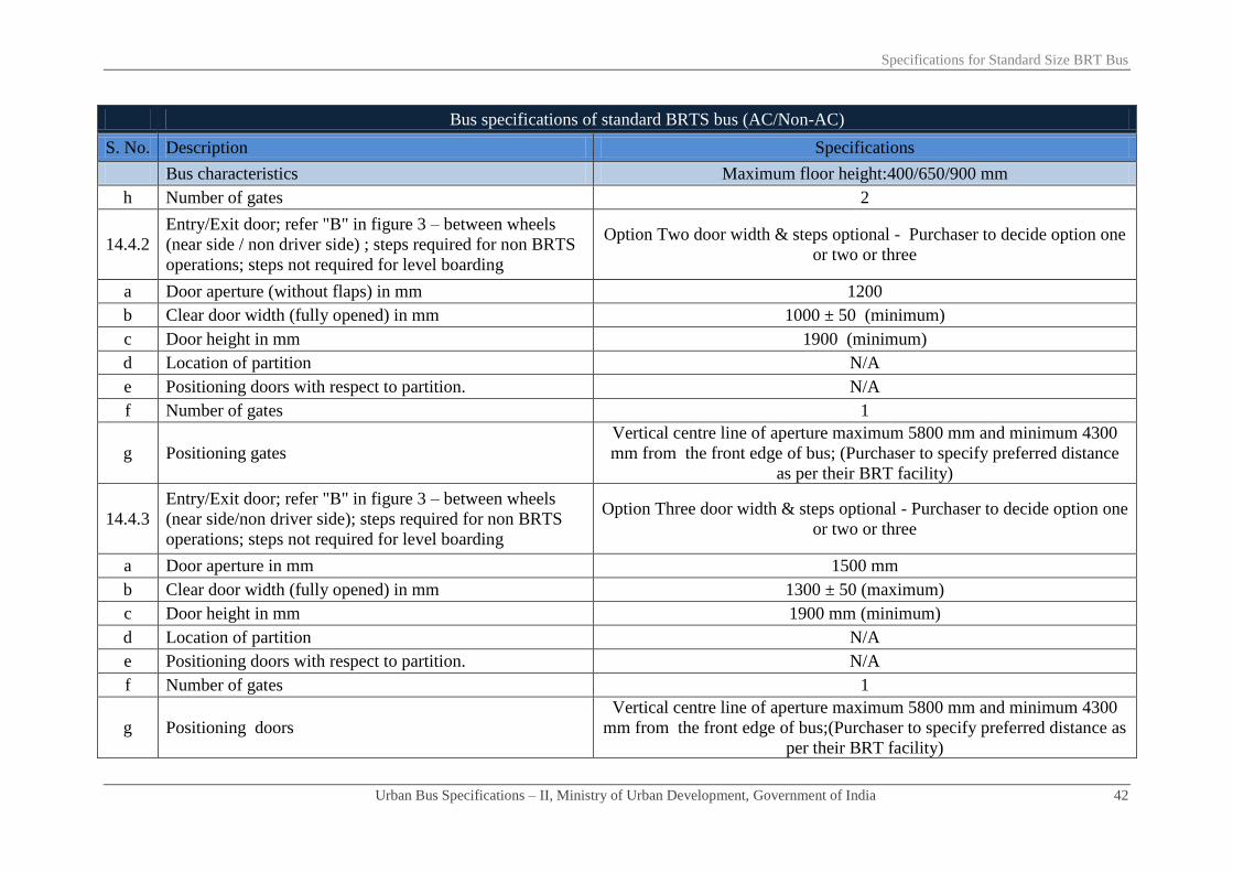
Specifications for Standard Size BRT Bus
Urban Bus Specifications – II, Ministry of Urban Development, Government of India 42
Bus specifications of standard BRTS bus (AC/Non-AC)
S. No. Description Specifications
Bus characteristics Maximum floor height:400/650/900 mm
h Number of gates 2
14.4.2
Entry/Exit door; refer "B" in figure 3 – between wheels
(near side / non driver side) ; steps required for non BRTS
operations; steps not required for level boarding
Option Two door width & steps optional - Purchaser to decide option one
or two or three
a Door aperture (without flaps) in mm 1200
b Clear door width (fully opened) in mm 1000 ± 50 (minimum)
c Door height in mm 1900 (minimum)
d Location of partition N/A
e Positioning doors with respect to partition. N/A
f Number of gates 1
g Positioning gates
Vertical centre line of aperture maximum 5800 mm and minimum 4300
mm from the front edge of bus; (Purchaser to specify preferred distance
as per their BRT facility)
14.4.3
Entry/Exit door; refer "B" in figure 3 – between wheels
(near side/non driver side); steps required for non BRTS
operations; steps not required for level boarding
Option Three door width & steps optional - Purchaser to decide option one
or two or three
a Door aperture in mm 1500 mm
b Clear door width (fully opened) in mm 1300 ± 50 (maximum)
c Door height in mm 1900 mm (minimum)
d Location of partition N/A
e Positioning doors with respect to partition. N/A
f Number of gates 1
g Positioning doors
Vertical centre line of aperture maximum 5800 mm and minimum 4300
mm from the front edge of bus;(Purchaser to specify preferred distance as
per their BRT facility)

Specifications for Standard Size BRT Bus
Urban Bus Specifications – II, Ministry of Urban Development, Government of India 43
Bus specifications of standard BRTS bus (AC/Non-AC)
S. No. Description Specifications
Bus characteristics Maximum floor height:400/650/900 mm
14.5 Entry/Exit doors, refer "D" in figure 3 - for off side/driver
side location - steps not required for level boarding Required
a Door aperture in mm 1200
b Clear door width (fully opened) in mm 1000 ± 50
c Door height in mm 1900 (minimum)
d Fixed partition between gates - full height Optional (Purchaser to decide)
e Width of partition in mm 400 (maximum)
f Location of partition
Vertical centre line of partition maximum 5800 mm and minimum 4300
mm from the front edge of bus; (Purchaser to specify preferred distance
as per their BRT facility)
g Positioning doors with respect to partition. One on each side of the partition
h Number of gates 2
14.6 Maximum first step height (mm) from ground - unladen &
un-kneeled position in buses with:
a Stepped type entry (maximum) 400
b Level entry (at station platform height) No steps required
14.7 Maximum height (mm) of other steps (where required)
a if door ahead of rear axle 250
b if door behind rear axle 250
14.8 Ramp for wheel chair at the gates wherever required
Sunken type wrap over (manually operated) ramp, for wheel chair of
PwDs, fitted on floor at gate in front of PwD seat anchorage. Suitable
design mechanism for 650/900mm floor height considering that floor level
of bus stops are at 400mm
a Dimensions Minimum width 900 mm
b Material Aluminium alloy with anti-slip coating

Specifications for Standard Size BRT Bus
Urban Bus Specifications – II, Ministry of Urban Development, Government of India 44
Bus specifications of standard BRTS bus (AC/Non-AC)
S. No. Description Specifications
Bus characteristics Maximum floor height:400/650/900 mm
c Load carrying capacity (in kilograms) > 300
d Device to prevent the wheel chair roll off the sides when
the length exceeds 1200mm √
e Device to lock wrapped up ramp √
f Kneel ramp control: (applicable in reference of clause 7.3) Kneeling arrangement for kneeling on left side severally and combined.
Kneeling upto 60mm
g Requirement for passengers with limited mobility √
i Wheel chair anchoring - minimum for one wheel chair √
ii Priority seats - minimum 2 seats √
iii Stop request √
h Emergency doors/exits or apertures (Numbers) As per AIS 052
Dimensions in mm As per AIS 052
i Door closing requirements for bus movement - Bus could move only after door closing completed
i
Power operated service door - construction & control
system of a power operated service door to be such that a
Passenger is unlikely to be injured/trapped between the
doors while closing.
As per AIS 052
ii Door components As per AIS 052
iii Door locks/locking systems/door retention items As per AIS 052
iv Door hinges As per AIS 052
15 Bus body
15.1 Design type approval As per Annexure-3
15.2 Bus structure - materials specifications etc Material to be decided by the manufacturer OR as per the tender
specifications issues by purchaser. Other requirements as per bus body

Specifications for Standard Size BRT Bus
Urban Bus Specifications – II, Ministry of Urban Development, Government of India 45
Bus specifications of standard BRTS bus (AC/Non-AC)
S. No. Description Specifications
Bus characteristics Maximum floor height:400/650/900 mm
code. Material should fulfil strength etc. requirements indicated under
Annexure-3
15.3 Insulation
a Roof structure Material to be decided by the manufacturer OR as per the tender
specifications issues by purchaser. Other requirements as per bus body
code. Material should fulfil strength etc. requirements indicated under
Annexure-3 b Engine compartment
15.4 Aluminium extruded sections for:
a Rub rail
Aluminium extrusion IS 733/1983 or better
b Decorative moulding
c Wire cover
d Wearing strip
e Foot step edging
f Panel beading
g Window frame
h Roof grab rail brackets
15.5 Floor type/Materials etc
a Not applicable for BRTS
b Type of Floor Uniform flat floor
c Not applicable for BRTS
d Steps on floor No steps/hump inside bus except where required for entry/exit
e Maximum floor slope 6%
f Floor surface material
12mm thickness phenolic resin bonded densified laminated compressed
wooden floor board (both side plain surface) having density of 1.2 gms/cc
conforming to IS 3513 (Part-3): type VI 1989 or latest. The flooring
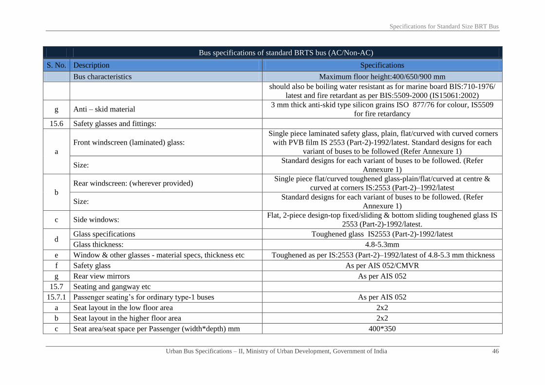
Specifications for Standard Size BRT Bus
Urban Bus Specifications – II, Ministry of Urban Development, Government of India 46
Bus specifications of standard BRTS bus (AC/Non-AC)
S. No. Description Specifications
Bus characteristics Maximum floor height:400/650/900 mm
should also be boiling water resistant as for marine board BIS:710-1976/
latest and fire retardant as per BIS:5509-2000 (IS15061:2002)
g Anti – skid material 3 mm thick anti-skid type silicon grains ISO 877/76 for colour, IS5509
for fire retardancy
15.6 Safety glasses and fittings:
a
Front windscreen (laminated) glass:
Single piece laminated safety glass, plain, flat/curved with curved corners
with PVB film IS 2553 (Part-2)-1992/latest. Standard designs for each
variant of buses to be followed (Refer Annexure 1)
Size: Standard designs for each variant of buses to be followed. (Refer
Annexure 1)
b
Rear windscreen: (wherever provided) Single piece flat/curved toughened glass-plain/flat/curved at centre &
curved at corners IS:2553 (Part-2)–1992/latest
Size: Standard designs for each variant of buses to be followed. (Refer
Annexure 1)
c Side windows: Flat, 2-piece design-top fixed/sliding & bottom sliding toughened glass IS
2553 (Part-2)-1992/latest.
d Glass specifications Toughened glass IS2553 (Part-2)-1992/latest
Glass thickness: 4.8-5.3mm
e Window & other glasses - material specs, thickness etc Toughened as per IS:2553 (Part-2)–1992/latest of 4.8-5.3 mm thickness
f Safety glass As per AIS 052/CMVR
g Rear view mirrors As per AIS 052
15.7 Seating and gangway etc
15.7.1 Passenger seating’s for ordinary type-1 buses As per AIS 052
a Seat layout in the low floor area 2x2
b Seat layout in the higher floor area 2x2
c Seat area/seat space per Passenger (width*depth) mm 400*350

Specifications for Standard Size BRT Bus
Urban Bus Specifications – II, Ministry of Urban Development, Government of India 47
Bus specifications of standard BRTS bus (AC/Non-AC)
S. No. Description Specifications
Bus characteristics Maximum floor height:400/650/900 mm
d Seat pitch - minimum (mm) As per AIS 052
e
Minimum backrest height-from floor to top of seat/headrest As per AIS 052
Seat base height-distance from floor to horizontal front
upper surface of seat cushion mm. As per AIS 052
Seat back rest height mm 375
f Torso angle (degrees) Minimum 12⁰
g Seat materials ‘PPLD/LDPE’ moulded AIS:023 & AIS 052 for performance
h Seat frame structure material where required: Frame structure of ERW steel tube
i Free height over seating position (mm) More than 900
Seat base height: As per AIS 052
j Clearance space for seated Passenger facing partition (mm) Minimum 350
k
Seat back/Pad material/Thickness: Polyurethane Foam IS15061:2002 (padding is optional)
Type: MDI Moulded IS 5509
Upholstery: Pile Fabric/Jekard 0.7-1.0 mm thickness
l Area for seated passengers (sq. mm.) type 1 NDX/SDX: 400*350
m Area for standee passengers (sq. mm.): As per AIS 052
n Number of seats including one for wheel chair 32 - 34
o Number of standees Calculation as per AIS 052
p Sitting/Standing Ratio Not required
q Headrest Not required
r Seats side facing location Not suggested except on wheel arches
s Seat arm Not required
t Magazine pouch Not required
u Individual seat row fans Not required

Specifications for Standard Size BRT Bus
Urban Bus Specifications – II, Ministry of Urban Development, Government of India 48
Bus specifications of standard BRTS bus (AC/Non-AC)
S. No. Description Specifications
Bus characteristics Maximum floor height:400/650/900 mm
v Reading lights Not required
w Seat back rest Fixed
x Seat belts & their anchorage Not necessary except diver seat & wheel chair (performance etc. as per
AIS 052)
y Performance & strength requirements of: √
i Driver seat As per AIS 023
ii Passenger seats As per AIS 023
15.7.2 Gangway:
a Minimum interior head room (centre line of gangway)
(mm) 1900 including that in the rear overhang area.
i At front axle: As per AIS 052
ii At rear axle: As per AIS 052
iii Other areas As per AIS 052
b Gangway width (mm) from gates to longitudinal space
between seats (access to service doors)
(Ref figure-1) minimum 700 mm excluding armrests (armrests are not
required) and including stanchions- will be measured from seat edge to
seat edge.
c Gangway width (mm) in longitudinal space between seats As above
d Gangway width (mm) in longitudinal space between seats
(rear of rear edge of the rear door in rear engine bus) As above
e Driver’s working space As per AIS 052
Driver’s seat As per AIS 052
15.8 Corrosion prevention & painting
As per clause 3.17 of AIS 052 a
Corrosion prevention treatment
Internal surfaces of structural members
External surfaces of structural members

Specifications for Standard Size BRT Bus
Urban Bus Specifications – II, Ministry of Urban Development, Government of India 49
Bus specifications of standard BRTS bus (AC/Non-AC)
S. No. Description Specifications
Bus characteristics Maximum floor height:400/650/900 mm
After drilling holes/welding
Inter metallic galvanic corrosion prevention
b Primer coating
c Painting:
16 Electrical system BIS marked, Copper conductors with fire retardant as per IS/ISO:
6722:2006 as per appropriate class. Conductor cross-section varying as
per circuit requirements, minimum cross-section 0.5 sq mm. Quality
marking may also be as per equivalent or better European, Japanese, US
standards
16.1 Electrical cables:
16.2 Conductor cross section
16.3 Safety requirements of electrical
As per AIS 052
a Fuse
b Isolation switches for electrical circuits where RMS value
of voltage exceeds 100 volts
c Location of cables away from heat sources
d Type approval of circuit diagram as per standards related to
electric equipments/wiring
e Battery cut - off switch (isolator switch):
16.4 Wind screen wiper:
Electrically operated with two wiper arms & blades, wiper motor heavy
duty steel body with minimum 2-Speed operation wiping system as per
CMVR/BIS:7827 Part-1, 2, 3 (Sec.1 & 2)/latest. As per AIS 011
a Wiper motor: Variable speed with time delay relay as per AIS 011.
b Wiper arm/blade: As per AIS 019/AIS 011
16.5 Driver cabin fan 1 number, 200 mm fan As per provision of CMVR, matching interiors
16.6 Lighting - internal & external and illumination As per AIS 052
16.7 Illumination requirements/performance of:

Specifications for Standard Size BRT Bus
Urban Bus Specifications – II, Ministry of Urban Development, Government of India 50
Bus specifications of standard BRTS bus (AC/Non-AC)
S. No. Description Specifications
Bus characteristics Maximum floor height:400/650/900 mm
a Dash board tell tale lighting/control lighting As per AIS 052
b Cabin lighting - luminous flux of all lamps for cabin
lighting As per AIS 052 with illumination level of ≥100 lux & ≤ 200 lux
c Passenger area lighting - luminous flux of all lamps for
Passenger area lighting As per AIS 052 with illumination level of ≥100 lux and ≤ 150 lux
17 ITS enabled bus As specified separately under ITS specifications
18 Safety related items:
18.1 Driver seat belt & anchorage duly type approved. ELR recoil type, 3 point mounting as per CMVR & AIS 052 conforming
to AIS 005 & 015
18.2 Passengers seat belt:
Not necessary except diver seat & wheel chair (performance etc. as per
AIS 052) Number/location
18.3 Driver/Passenger/wheelchair seat belt anchorage
18.4 Fire extinguisher: As per AIS 052
18.5 First aid box: 1 number, as per provision of CMVR
18.6 Handrails minimum length*diameter*height above floor in
mm
Colour contrasting and slip resistant of aluminium tubing 32 mm dia, 3
mm thick. Rest as per AIS 052
18.7 Handholds: Colour contrasting and slip resistant. 2 to 4 numbers. Handholds per bay.
Rest as per AIS 052
18.8 Stanchions:
Vertically fitted, aluminium tubing with Colour contrasting and slip
resistant. 40 mm dia & 3.15 mm thick. Rest as per AIS 052. As an
alternative to stanchions mounted on bus floor, stanchions mounted on top
of seat frames (new version seats) be explored (refer figure-2).
18.9 Not applicable for BRTS
18.10 Passenger stop request signal
High visibility bell pushes/pully chord/touch tape shall be fitted at a height
of 1.2 meter on all alternate stanchions mainly for persons with
disabilities. (optional)

Specifications for Standard Size BRT Bus
Urban Bus Specifications – II, Ministry of Urban Development, Government of India 51
Bus specifications of standard BRTS bus (AC/Non-AC)
S. No. Description Specifications
Bus characteristics Maximum floor height:400/650/900 mm
18.11 Window guardrails:
a In all school buses - minimum numbers. Not Applicable
b In all other buses- minimum numbers. As per AIS 052
c In AC super deluxe buses
As per AIS 052 d Other details:
i First guard rail at a height from window sill in mm
ii The distance between two guard rails in mm
18.12 Entrance/Exit guard/Step well guard: 800 mm minimum height extending ≥ 100mm more than centre line of
sitting position of the Passenger.
18.13 Emergency exit doors, warning devices etc: As per AIS 052/CMVR
18.14 Front/Rear door, step well lights, door open sign Incandescent bulb/LED as per AIS 008
18.15 Mirrors right/left side exterior/interior: Convex as per AIS: 001 & 002. Interior with double curvature
18.16 Towing device front/rear Heavy duty 1.2 times (minimum) the kerb weight of the bus with 30⁰ of
the longitudinal axis of the bus. As per CMVR & IS 9760 - ring type
18.17 Warning triangle As per AIS 052/CMVR
18.18 Fog lighting As per AIS 052/CMVR
18.19 Bumpers - front and rear
Both made of steel or impact resistant polymer or combination of both
meeting requirement of an energy absorbing system
Impact strength for bumpers Meet requirements of Para 6.3.1 of AIS 052
19 Miscellaneous items/requirements
19.1 Windows
a Type of window Sliding type window panes except AC bus
b Minimum height of window aperture (clear vision)3 in mm ≥ 950
3 Clear vision includes partition between fixed and sliding glass subject to a maximum width of 100 mm

Specifications for Standard Size BRT Bus
Urban Bus Specifications – II, Ministry of Urban Development, Government of India 52
Bus specifications of standard BRTS bus (AC/Non-AC)
S. No. Description Specifications
Bus characteristics Maximum floor height:400/650/900 mm
c Minimum height of upper edge of window aperture from
bus floor As per AIS 052
d Minimum width of windows (clear vision zone) As per AIS 052
19.2 Cabin luggage carrier As per AIS 052
19.3 Life cycle requirements of bus (whichever is earlier) 12 years or 10,00,000 km
20 Air conditioning system - test procedure for type approval
20.1 Specifications a) For up to 42°C of saloon temperature and b) For > 42°C of saloon
temperature
20.2 Target results
a) 24± 4°C (up to 42°C )
b) Temperature gradient of 15° ( > 42°C of saloon temperature) eg. If the
saloon temperature is 45o, then the target temperature inside the bus is 45
o-
15o= 30
o
c) Minimum average air velocity at air vent is 4.5 m/s
20.3 Apparatus Lab condition and heating chamber
20.4 Procedure
1. Soak for 1 hour
2. At 2000 rpm
3.Upto 42°C: pull down time 30 minutes (maximum) (for more than 42°C
of saloon temperature, pull down time within 40 minutes (maximum))
4. Thermocouple to be placed over place minimum 20 numbers at nose
level
20.5
Air curtains on entry/exit gates to avoid loss/gain of heat
and or cool air when doors are frequently opened for
boarding/alighting of Passenger with min air flow of
1000±50 m³/hr at each gate. Type of air curtains at entry
exit gates their power consumption etc be accounted for
while deciding engine power, etc
Required

Specifications for Standard Size BRT Bus
Urban Bus Specifications – II, Ministry of Urban Development, Government of India 53
Bus specifications of standard BRTS bus (AC/Non-AC)
S. No. Description Specifications
Bus characteristics Maximum floor height:400/650/900 mm
21 Additional requirements
21.1 Air circulations and ventilation in driver's area
An air passage/duct/roof hatch to be provided in driver area at a suitable
location for proper inflow of air inside the driver cab
Drivers work area to be provided with blower or suitable device (200 mm
diameter fan) to ensure proper ventilation. These devices may be capable
of 3 – speed adjustment
21.2
Maximum noise levels inside the saloon (irrespective of
AC, non-AC/fuel type/engine location)-test procedure as
per AIS 020
84 dba (to be achieved a maximum noise level of 81 dba from 1st April
2015 onwards)
22 Fuel efficiency requirement While tendering purchaser may take into account the higher weight age for
more fuel efficient vehicle under standard test conditions

Chapter - 05
Specifications for Mini and Midi
BRT bus

Specifications for Mini and Midi BRT Bus
Urban Bus Specifications – II, Ministry of Urban Development, Government of India 54
Bus specifications for Mini and Midi BRT buses (AC/Non-AC)
S. No. Description Specifications
Mini Buses Midi buses
Maximum Bus Floor heights in mm
Floor height of 400,
650 or 900 mm shall
be uniform inside
the vehicle
Floor height of 400,
650 mm shall be
uniform inside the
vehicle
Floor height of
900 mm shall
be uniform
inside the
vehicle
Definition of Low Floor area
“Low floor area shall not be less than 50% of the total saloon
area (excluding front wheel boxes and driver’s cab) and shall
not be ramped in the longitudinal plane”
1 Propulsion System ICE, Electrical, Hybrid, Fuel Cell
2 Fuel-options Fuel to be compatible with propulsion system & prescribed
emission norms
3 Engine Fuel compatible engine
3.1 Engine HP sufficient to provide:
a Rated performance at GVW in a stop/start urban operations Geared maximum speed without speed limiter to be 75 kmph
b Acceleration (meter/sec²) ≥ 0.8
c Attain Bus speed of 0-30 kmph in seconds ≤ 10.5
d Maximum speed Geared maximum speed without speed limiter to be 75 kmph
e Grade ability from stop at GVW 17%
f Rated HP/torque preferably at lower rpm range Maximum engine torque required at lower range of RPM and
spread over a wider range of RPM
g Power requirements for Air conditioning system, ITS, etc Required
3.2 Emission norms BS III/BS IV/latest as applicable

Specifications for Mini and Midi BRT Bus
Urban Bus Specifications – II, Ministry of Urban Development, Government of India 55
Bus specifications for Mini and Midi BRT buses (AC/Non-AC)
S. No. Description Specifications
Mini Buses Midi buses
3.3 Engine management
Engine oil pressure, engine coolant temperature, engine speed
in RPM, vehicle speed, engine % load (torque), diagnostic
message (engine specific)
3.4 Engine operational requirements
Engine should be able to operate efficiently at ambient
temperatures of approximately 0o to 50
oC, humidity level
from 5% to 100%, and altitude levels of upto 2000 meters,
generally operating in the semi arid zone/hilly region
prevailing in the area.
3.5 Engine location Optional
3.6 Transmission
a Automated Manual Transmission (AMT) Purchaser to select any one transmission system. However,
rear engine buses to have either automatic or automated
manual transmission system only. (any bus delivered after 1st
April, 2015 will mandatorily have either automatic or
automated manual transmission system)
b Manual synchromesh - forward speeds (minimum 5) & constant mesh
on reverse gear (MT)
c Automatic transmission with torque convertor. Neutral during stops
d Mounting Column or floor Optional
4 Operational safety
Transmission system to be fitted with a mechanism which
makes it possible to engage reverse gear only when vehicle is
stationary (applicable for automatic & automatic manual
transmission)
5 Clutch (where applicable) Dry, single plate, power assisted operation
5.1 Rear axle Single reduction, hypoid gears, full floating axle shafts with
optimal gear ratios suitable for urban operations
5.2 Front axle Heavy duty reverse Elliot type axle suitable for various floor
heights
6 Steering system Hydraulic power steering

Specifications for Mini and Midi BRT Bus
Urban Bus Specifications – II, Ministry of Urban Development, Government of India 56
Bus specifications for Mini and Midi BRT buses (AC/Non-AC)
S. No. Description Specifications
Mini Buses Midi buses
7 Suspension system Optional (air suspension/Independent/parabolic/weveller)-
irrespective of the type of suspension, floor level of bus
should not go beyond maximum floor height (any bus
delivered after 1st April, 2015 will mandatorily have air
suspension or superior)
7.1 Front
7.2 Rear
7.3 Kneeling (mm) applicable in case of air suspension Not Required
7.4 Anti roll bars/stabilizers1 Both front and rear
7.5 Shock absorbers Hydraulic double acting 2 at front & 2/4 at rear
7.6 Controls (optional) Electronically controlled air suspension system
8 Braking system
Dual circuit full air brakes, with preferably disc type
arrangement for front and drum at rear brakes. Graduated
hand controlled, spring actuated parking brakes acting on rear
wheels (any bus delivered after 1st April, 2015 will
mandatorily have disc brake in front)
8.1 Anti skid anti brake locking system (ABS) As per CMVR
8.2 Electronic controls (optional) √
9 Electrical system 12/242 volt DC 24 volt DC
9.1 Batteries:
Low maintenance type lead acid batteries for 12/24 V (as
applicable) system- performances as per BIS: 14257-1995
(latest). 2*12V of commensurate capacity. Maintenance free
batteries preferred.
9.2 Self starter 12/24V2 24V
1 Optional in case of independent suspension
2 24 Volt mandatory after April 2015

Specifications for Mini and Midi BRT Bus
Urban Bus Specifications – II, Ministry of Urban Development, Government of India 57
Bus specifications for Mini and Midi BRT buses (AC/Non-AC)
S. No. Description Specifications
Mini Buses Midi buses
9.3 Alternator 12/24V2 24V
9.4 Electrical wiring & controls –type As specified separately under ITS specifications
10 Speed limiting device (optional):
Electronic type duly approved/certified as per AIS –
018/2001 or latest, tamper proof and be adjusted to applicable
speed limit
11 Tyres Steel radial tube-less. Size and performance as per CMVR
12 Fuel tank
Capacity of diesel fuel tank/CNG cylinders adequate to
enable bus operation of up to 250 km between consecutive
fillings
Fuel tank location Optional
13 Bus characteristics
13.1 Bus dimensions in mm
a Overall length (over body excluding bumper) ≤ 7000 9000 (tolerance + 400 mm)
b Overall width (sole bar/floor level- extreme points) ≤ 2200 ≤ 2500 (≤ 2200 Preferred; Purchaser to
specify)
c Overall height (unladen-at extreme point) 3300 (maximum) 3800 (maximum)
d Wheel-base ≥ 3000 ≤ 5000
i Front overhang As per CMVR
ii Rear overhang As per CMVR
13.2 Turning circle radius (mm) - minimum As per CMVR
13.3 Floor height above ground (mm) 900/650/400 ± 20 650/400 ± 20 900 ± 20
13.4 Clearances (mm)
a Axle clearance (mm) Minimum.190 mm
b Wheel area clearance (mm) > 220 mm for parts fixed to bus body & > 170 mm for the

Specifications for Mini and Midi BRT Bus
Urban Bus Specifications – II, Ministry of Urban Development, Government of India 58
Bus specifications for Mini and Midi BRT buses (AC/Non-AC)
S. No. Description Specifications
Mini Buses Midi buses
parts moving vertically with axle.
c Minimum ground clearance (un-kneeled) at GVW Within the wheelbase not less than 240mm.
13.5 Angles (degrees)
a Angle of approach (unladen) Not less than 8.0°
b Angle of departure (unladen) Not less than 8.5°
c Ramp over angle (half of break-over angle) Minimum 4.8°
14 Bus Gates/Doors
14.1 Entry exit gates with doors
a Operating mechanism
Electrical/Electro
pneumatically
controlled
Electro pneumatically controlled
b Maximum opening closing time in seconds per operation 4
c Positions of door controls As per AIS 052
d Passenger safety system - allowing bus motion on doors closing √
14.2 Front service doors - near side: √
a Door aperture (without flaps) in mm As per AIS 052
b Clear door width (fully opened) in mm As per AIS 052
c Door height in mm As per AIS 052
d Positioning front service gate As per AIS 052
e Number of gates minimum. 1
14.3 Rear service doors (near side): where provided Optional and at the discretion of purchaser
a Door aperture (without flaps) in mm As per AIS 052
b Clear door width (fully opened) As per AIS 052

Specifications for Mini and Midi BRT Bus
Urban Bus Specifications – II, Ministry of Urban Development, Government of India 59
Bus specifications for Mini and Midi BRT buses (AC/Non-AC)
S. No. Description Specifications
Mini Buses Midi buses
c Door height As per AIS 052
d Positioning rear door with respect to centre line of rear axle As per AIS 052
Preferably rear edge of gate 1500 mm
ahead of centre line of rear axle or
front edge of gate 1500mm behind
centre line of rear axle
e Number of gates 1
14.4 Entry/Exit door – between wheels (near side/non driver side); station
platform 400/650/900 mm level boarding Required
a Door aperture in mm 1200 mm or 1500 mm (Purchaser to specify)
b Clear door width (fully opened) 1000 ± 50 minimum for 1200 mm or 1300 ± 50 maximum
for 1500 mm
c Door height 1900 mm (minimum)
d
Fixed partition between gates - full height N/A
Width of partition in mm N/A
Location of partition N/A
e Positioning doors with respect to partition. N/A
f Number of gates 1
g Positioning doors Vertical centre line of the door aperture is centre line of
wheel base
14.5 Location of gates Location on off side/driver side (to match the height of
platform without steps)
a Door aperture (without flaps) in mm 1500 800
b Clear door width (fully opened) 1300 ± 50 650
c Door height 1900 mm (minimum)

Specifications for Mini and Midi BRT Bus
Urban Bus Specifications – II, Ministry of Urban Development, Government of India 60
Bus specifications for Mini and Midi BRT buses (AC/Non-AC)
S. No. Description Specifications
Mini Buses Midi buses
d Number of gates minimum 1 2
d
Fixed partition between gates - full height N/A Optional (Purchaser to decide)
Width of partition in mm N/A 400 (maximum)
Location of partition N/A Vertical centre line of the partition is
centre line of wheel base
e Positioning doors with respect to partition. One on each side of partition
f Number of gates 1 2
14.5 Intentionally left blank
14.6 Maximum first step height (mm) from ground - unladen & un-kneeled
position in buses with:
a Stepped type entry 400
b No step entry/level entry (at station platform height.) 900/650/400 900/650/400
14.7 Maximum height (mm) of other steps In no case, bus floor height should go beyond the maximum
floor height.
a if door ahead of rear axle 250 250
b if door behind rear axle 250 250
14.8 Ramp for wheel chair at the gates, as applicable
Sunken type wrap over (manually operated) ramp, for wheel
chair of PwDs, fitted on floor at gate in front of PwD seat
anchorage. Suitable design mechanism for 650/900mm floor
height considering that floor level of bus stops are at 400mm
a Dimensions
As applicable for 14.8
b Material
c Load carrying capacity
d Device to prevent the wheel chair roll off the sides when the length
exceeds 1200mm

Specifications for Mini and Midi BRT Bus
Urban Bus Specifications – II, Ministry of Urban Development, Government of India 61
Bus specifications for Mini and Midi BRT buses (AC/Non-AC)
S. No. Description Specifications
Mini Buses Midi buses
e Device to lock wrapped up ramp
f Kneel ramp control: (applicable in reference of clause 7.3) Kneeling arrangement for kneeling on left side severally and
combined. Kneeling up to 60mm
g Requirement for passenger with limited mobility √
i Wheel chair anchoring - minimum for one wheel chair √
ii Priority seats - minimum 2 seats √
iii Stop request- on every pillar √
h Emergency doors/exits or apertures (numbers) As per AIS 052
Dimensions in mm As per AIS 052
i Passenger safety system - allowing bus motion on doors closing and
doors opening only when the bus is stopped Mandatory
i
Power operated service door - construction & control system of a
power operated service door be such that a Passenger is unlikely to be
injured/trapped between the doors while closing.
As per AIS 052
ii Door components As per AIS 052
iii Door locks/locking systems/door retention items As per AIS 052
iv Door hinges As per AIS 052
15 Bus body
15.1 Design type approval As per Annexure-3
15.2 Bus structure - materials specifications etc
Material to be decided by the manufacturer OR as per the
tender specifications issues by purchaser. Other requirements
as per bus body code. Material should fulfil strength etc.

Specifications for Mini and Midi BRT Bus
Urban Bus Specifications – II, Ministry of Urban Development, Government of India 62
Bus specifications for Mini and Midi BRT buses (AC/Non-AC)
S. No. Description Specifications
Mini Buses Midi buses
requirements indicated under Annexure-3
15.3 Insulation
a Roof structure/body Material to be decided by the manufacturer OR as per the
tender specifications issues by purchaser. Other requirements
as per bus body code. Material should fulfil strength etc.
requirements indicated under Annexure-3 b Engine compartment
15.4 Aluminium extruded sections for:
a Rub rail
Aluminium extrusion IS 733/1983 or better
b Decorative moulding
c Wire cover
d Wearing strip
e Foot step edging
f Panel beading
g Window frame
h Roof grab rail brackets
15.5 Floor type/materials etc
a Type of floor N/A
b Type of floor Uniform floor inside bus without steps
c Steps on floor Not required
d Steps on floor N/A
e Maximum floor slope As per AIS 052
f Floor surface material
12mm thickness phenolic resin bonded densified laminated
compressed wooden floor board (both side plain surface)
having density of 1.2 gms/cc conforming to IS 3513(Part-3):
type VI 1989 or latest. The flooring should also be boiling

Specifications for Mini and Midi BRT Bus
Urban Bus Specifications – II, Ministry of Urban Development, Government of India 63
Bus specifications for Mini and Midi BRT buses (AC/Non-AC)
S. No. Description Specifications
Mini Buses Midi buses
water resistant as for marine board BIS:710-1976/ latest and
fire retardant as per BIS:5509-2000(IS15061:2002)
g Anti – skid material 3 mm thick anti-skid type silicon grains ISO 877/76 for
colour, IS5509 for fire retardancy
15.6 Safety glasses and fittings:
a
Front windscreen (laminated) glass:
Single piece laminated safety glass, plain, flat/curved with
curved corners with PVB film IS 2553 (Part-2)-1992/latest.
Standard designs for each variant of buses to be followed
(Refer Annexure 1)
Size: Standard designs for each variant of buses to be followed.
(Refer Annexure 1)
b
Rear windscreen: (wherever provided) Single piece flat/curved toughened glass-plain/flat/curved at
centre & curved at corners IS 2553(Part-2)–1992/latest
Size: Standard designs for each variant of buses to be followed.
(Refer Annexure 1)
c Side windows: Flat, 2-piece design-top fixed/sliding & bottom sliding
toughened glass IS 2553 (Part-2)-1992/latest.
d Glass specifications Toughened glass IS2553 (Part-2)-1992/latest
Glass thickness: Minimum 4.0 mm 4.8-5.3mm
e Window & other glasses - material specifications, thickness etc Toughened as per IS 2553 (Part-2)–1992/latest of 4.8-5.3
mm thickness
f Safety glass As per AIS 052/CMVR
g Rear view mirrors As per AIS 052
15.7 Seating and gangway etc
15.7.1 Passenger seating for ordinary type-1 buses As per AIS 052
a Seat layout in the low floor area As per AIS 052

Specifications for Mini and Midi BRT Bus
Urban Bus Specifications – II, Ministry of Urban Development, Government of India 64
Bus specifications for Mini and Midi BRT buses (AC/Non-AC)
S. No. Description Specifications
Mini Buses Midi buses
b Seat layout in the higher floor area
c Seat area/seat space per Passenger (width*depth) mm 400*350
d Seat pitch - minimum in mm As per AIS 052
e
Minimum backrest height-from floor to top of seat/headrest As per AIS 052
Seat base height-distance from floor to horizontal front upper surface
of seat cushion mm. As per AIS 052
Seat back rest height in mm 350 375
f Torso angle (degrees) Minimum 12⁰
g Seat materials ‘PPLD/LDPE’ moulded AIS:023 & bus code for
performance
h Seat frame structure material where required: Frame Structure of ERW steel tube
i Free height over seating position in mm More than 800
Seat base height: As per AIS 052
j Clearance space for seated Passenger facing partition mm AIS 052
k
Seat back/Pad material/Thickness: (optional) Polyurethane foam IS15061:2002, 30±5 mm (padding is
optional)
Type: MDI moulded IS 5509
Upholstery: Pile Fabric/Jekard 0.7-1mm thickness
l Area for seated passengers (sq.mm.): 400*350
m Area for standee passengers (sq.mm.): As per AIS 052
n Number of seats including one for wheel chair 13-22 23-34
o Number of standees (calculation as per AIS 052) As per AIS 052
p Seats side facing location Not suggested except on wheel arches
q Seat back rest Fixed

Specifications for Mini and Midi BRT Bus
Urban Bus Specifications – II, Ministry of Urban Development, Government of India 65
Bus specifications for Mini and Midi BRT buses (AC/Non-AC)
S. No. Description Specifications
Mini Buses Midi buses
r Seat belts & their anchorage Not necessary except diver seat & wheel chair (performance
etc. as per AIS 052)
s Performance & strength requirements of: √
i Driver seat As per AIS 023
ii Passenger seats As per AIS 023
15.7.2 Gangway:
a Minimum interior head room (centre line of gangway) in mm
1750 mm for
standee type &1500
mm for non standee
type
1900 mm including that in the rear
overhang area.
i At front axle:
As per AIS 052 ii At rear axle:
iii Other areas
b Gangway Width (mm) from gates to longitudinal space between rows
of seats (Access to service doors)
(Refer figure-1) minimum 600 mm excluding armrests
(armrests are not required) and including stanchions- will be
measured from seat edge to seat edge.
c Gangway Width (mm) in longitudinal space between rows of seats As above
d Gangway Width (mm) in longitudinal space between rows of seats
(rear of rear edge of the rear door in RE bus) As above
e Driver’s working space As per AIS 052
Driver’s seat As per AIS 023 & AIS 052
15.8 Corrosion prevention & painting As per clause 3.17 of AIS 052
a Corrosion prevention treatment
As per clause 3.17 of AIS 052 Internal surfaces of structural members

Specifications for Mini and Midi BRT Bus
Urban Bus Specifications – II, Ministry of Urban Development, Government of India 66
Bus specifications for Mini and Midi BRT buses (AC/Non-AC)
S. No. Description Specifications
Mini Buses Midi buses
External surfaces of structural members
After drilling holes/welding
Inter metallic galvanic corrosion prevention
b Primer coating
c Painting:
16 Electricals
16.1 Electrical cables:
BIS marked, copper conductors with fire retardant as per
IS/ISO: 6722:2006 as per appropriate class. Conductor cross-
section varying as per circuit requirements, minimum cross-
section 0.5 sq mm. Quality marking may also be as per
equivalent or better European, Japanese, US standards
16.2 Conductor cross section As above and suitable to carry rated current (Japanese auto
Standard JASO D0609-75 AV)
16.3 Safety requirements of electrical As per AIS 052
a Fuse
As per AIS 052 - fuse of rated current 1.5 times the load
current of electrical equipment. Necessary in every electrical
circuit
b Isolation switches for electrical circuits where RMS value of voltage
exceeds 100 volts
As per AIS 052- Isolation switch required for each such
circuit
c Location of cables away from heat sources As per AIS 052- Required for each such circuit
d Type approval of circuit diagram as per standards related to electric
equipments/wiring As per AIS 052 - Required for all items
e Cable insulation with respect to heat As per AIS 052
f Battery cut - off switch (isolator switch): Heavy-duty type capable of carrying & interrupting total
circuit load. 1 each near battery/driver
16.4 Wind screen wiper: Electrically operated with two wiper arms & blades, wiper

Specifications for Mini and Midi BRT Bus
Urban Bus Specifications – II, Ministry of Urban Development, Government of India 67
Bus specifications for Mini and Midi BRT buses (AC/Non-AC)
S. No. Description Specifications
Mini Buses Midi buses
motor heavy duty steel body with minimum 2-Speed
operation wiping system as per CMVR/BIS 7827 part-1, 2, 3
(Sec.1 & 2)/latest. As per AIS 011
a Wiper motor: Variable speed with time delay relay as per AIS11.
b Wiper arm/blade: AIS 019/AIS011
16.5 Driver cabin fan 1 number, 200mm fan as per provision of CMVR, matching
interiors
16.6 Lighting - internal & external and illumination As per AIS 052.
16.7 Illumination requirements/performance of:
a Dash Board Tell tale lighting/control lighting As per AIS 052 & bulbs tested for photometry as per IS
1606:1996
b Cabin Lighting - luminous flux of all lamps for cabin lighting As per AIS 052 with illumination level of ≥ 100 lux & ≤ 200
lux
c Passenger area lighting - luminous flux of all lamps for Passenger
area lighting
As per AIS 052 with illumination level of ≥ 100 lux and ≤
150 lux
17 ITS enabled bus As specified separately under ITS specifications
18 Safety related items:
18.1 Driver seat belt & anchorage duly type approved. ELR recoil type, 3 point mounting as per CMVR & AIS 052
conforming to AIS: 005&015.
18.2 Passengers seat belt:
Not necessary except diver seat & wheel chair (performance
etc. as per AIS 052) Number:
18.3 Driver/Passenger/wheelchair Seat Belt Anchorage
18.4 Fire extinguisher: As per AIS 052
18.5 First aid box: 1 number, as per provision of CMVR

Specifications for Mini and Midi BRT Bus
Urban Bus Specifications – II, Ministry of Urban Development, Government of India 68
Bus specifications for Mini and Midi BRT buses (AC/Non-AC)
S. No. Description Specifications
Mini Buses Midi buses
18.6 Handrails Minimum length*diameter* height above floor in mm Colour contrasting and slip resistant of aluminium tubing 32
mm dia, 3 mm thick.
18.7 Handholds: Colour contrasting and slip resistant. 2 to 4 Numbers. hand
holds per bay
18.8 Stanchions:
Vertically fitted, aluminium tubing with Colour contrasting
and slip resistant. 40 mm dia & 3.15 mm thick. Rest As per
AIS 052. As an alternative to stanchions mounted on bus
floor, stanchions mounted on top of seat frames (new version
seats) be explored (ref figure-2).
18.9 Bells for Passenger convenience High visibility bell pushes shall be fitted at a height of 1.2
meter on all alternate stanchions. These would assist PwDs
18.10 Left blank
18.11 Window Guardrails:
As per AIS 052.
a In all school buses - minimum numbers.
b In all other buses - minimum numbers.
c In AC super deluxe buses
d Other details:
i First guard rail at a height from window sill in mm
ii The distance between two guard rails in mm
18.12 Entrance/Exit Guard/Step well guard: 800 mm minimum height extending ≥ 100 mm more than
centre line of sitting position of the Passenger.
18.13 Emergency exit doors, warning devices etc: As per AIS 052/CMVR
18.14 Front/rear door, step well lights, door open sign Incandescent bulb/LED as per AIS 008
18.15 Mirrors right/left side exterior/interior: Convex as per AIS 001 & 002. Interior with double curvature
18.16 Towing device front/rear Heavy duty 1.2 times (minimum) the kerb weight of the bus
with 30o of the longitudinal axis of the bus. As per CMVR &

Specifications for Mini and Midi BRT Bus
Urban Bus Specifications – II, Ministry of Urban Development, Government of India 69
Bus specifications for Mini and Midi BRT buses (AC/Non-AC)
S. No. Description Specifications
Mini Buses Midi buses
IS 9760 - ring type
18.17 Warning triangle As per AIS 052/CMVR
18.18 Fog Lighting As per AIS 052/CMVR
18.19 Bumpers - front and rear
Both made of Steel or impact resistant polymer or
combination of both meeting requirement of an energy
absorbing system
Impact strength for bumpers Meet requirements of Para 6.3.1 of AIS 052
19 Miscellaneous items/requirements
19.1 Windows
a Type of window Sliding type window panes except AC bus
b Minimum height of window aperture (clear vision)3 ≥ 500 mm ≥ 950 mm
c Minimum height of upper edge of window aperture from bus floor As per AIS 052
d Minimum width of windows (clear vision zone) As per AIS 052
19.2 Cabin luggage carrier As per AIS 052
19.3 Life cycle requirements of bus (whichever is earlier) 12 years or 10,00,000 km
20 Air conditioning system - test procedure for type approval
20.1 Specifications a) For up to 42°C of saloon temperature and b) For > 42°C
of saloon temperature
20.2 Target results
a) 24+/- 4°C (Up to 42°C )
b) Temperature Gradient of 15⁰ ( > 42°C of saloon
temperature) e.g. If the saloon temperature is 45o, then the
3 Clear vision includes partition between fixed and sliding glass subject to a maximum width of 100 mm

Specifications for Mini and Midi BRT Bus
Urban Bus Specifications – II, Ministry of Urban Development, Government of India 70
Bus specifications for Mini and Midi BRT buses (AC/Non-AC)
S. No. Description Specifications
Mini Buses Midi buses
target temperature inside the bus is 45o-15
o= 30
o
c) Min avg. air velocity at air vent is 4.5 m/s
20.3 Apparatus Lab condition and heating chamber
20.4 Procedure
1. Soak for 1 hour
2. At 2000 rpm
3.Upto 42°C: pull down time 30 minutes (maximum) (for
more than 42°C of saloon temperature, pull down time within
40 min (maximum))
4. Thermocouple to be placed over place minimum 20
numbers. at nose level
20.5
Air curtains on entry/exit gates to avoid loss/gain of heat and or cool
air when doors are frequently opened for boarding/alighting of
Passenger with min air flow of 1000±50 m³/hr at each gate. Type of
air curtains at entry exit gates their power consumption etc be
accounted for while deciding engine power, etc
Required
21 Additional requirements
21.1 Air circulations and ventilation in driver's area
An air passage/duct/roof hatch to be provided in driver area at
a suitable location for proper inflow of air inside the driver
cab
Drivers work area to be provided with blower or
suitable device (200 mm diameter fan) to ensure
proper ventilation. These devices may be capable of 3
– speed adjustment
21.2 Maximum noise levels inside the saloon (irrespective of AC, non-
AC/fuel type/engine location)-test procedure as per AIS 020
84 dba (to be achieved a maximum noise level of 81dba from
1st April 2015 onwards)

Specifications for Mini and Midi BRT Bus
Urban Bus Specifications – II, Ministry of Urban Development, Government of India 71
Bus specifications for Mini and Midi BRT buses (AC/Non-AC)
S. No. Description Specifications
Mini Buses Midi buses
22 Fuel efficiency requirement
While tendering purchaser may take into account the higher
weight age for more fuel efficient vehicle under standard test
conditions

Chapter - 06
Specifications for Standard size bus of
Premium segment

Specifications for Standard Size Bus of Premium Segment
Urban Bus Specifications – II, Ministry of Urban Development, Government of India 72
Bus specifications for Standard Bus of Premium Segment (Air conditioned)
S. No. Description Specifications
Bus characteristics Maximum floor height:900 mm
Bus floor heights
As per AIS 052 (this segment of buses are envisaged to be more comfortable for
seating passengers with lesser standees). However all buses to be delivered after 1st
April 2015 will follow the same definition as in the case of non-premium buses) i.e.
“low floor area shall not be less than 50% of the total saloon area (excluding front
wheel boxes and driver’s cab) and shall not be ramped in the longitudinal plane”
1 Propulsion system Internal combustion engine, electrical, hybrid, fuel cell
2 Fuels-options Diesel/CNG/ULSD/hydrogen
3 Engine
3.1 Fuel recommended Fuel to be compatible with propulsion system.
3.2 Engine HP sufficient to provide:
a Rated performance at GVW in a stop/start urban
operations Maximum vehicle speed of up to 75 kmph bus GVW
b Acceleration (meter/sec²) complemented with
minimum 1000 Nm torque 0.8
c Attain bus speed of 0-30 kmph 9.0 seconds
d Maximum speed ≤ 75 kmph
e Grade ability from stop at 1.5 GVW 17%
f Rated HP/torque preferably at lower rpm range HP rating designed to provide rated torque of minimum 1000 Nm (under full load)
preferably at lower range.
3.3
Maximum Fuel efficiency kmpl or kmpkg. Vehicle
Manufacturer to specify fuel efficiency in terms of
kmpl or kmpkg under standard 13 mode urban
operating cycle and rated loading. While tendering,
purchaser may take into account the higher weight
age for more fuel efficient vehicle
√
3.4 Emission norms BS III/BS IV or latest as applicable

Specifications for Standard Size Bus of Premium Segment
Urban Bus Specifications – II, Ministry of Urban Development, Government of India 73
Bus specifications for Standard Bus of Premium Segment (Air conditioned)
S. No. Description Specifications
Bus characteristics Maximum floor height:900 mm
3.5 Electronic engine management (EMS) system with
following provisions amongst others:
Full electronic management of engine including on-board diagnostic and driver
alerts e.g. engine oil pressure, engine coolant temperature, engine speed in RPM,
vehicle speed, diagnostic details message (engine specific)
a Fault tracing and diagnostics √
b
Information generation about driver and vehicle
performance as specified as part of ITS
specifications
√
3.5.1 Typical EMS parameters √
a Fuel feed & fuel delivery system status related to: √
i Feed pump pressure √
ii Fuel delivery pressure √
iii Booster pressure and temperature √
b Coolant Status related to: √
i Coolant level √
ii Coolant temperature √
iii Coolant pressure √
c Engine oil status related to: √
i Oil level √
ii Oil temperature √
iii Oil pressure √
d Accelerator pedal position √
e Water in fuel indicator √
f Injector status √
g Engine position timing sensor √
h Engine speed sensor √

Specifications for Standard Size Bus of Premium Segment
Urban Bus Specifications – II, Ministry of Urban Development, Government of India 74
Bus specifications for Standard Bus of Premium Segment (Air conditioned)
S. No. Description Specifications
Bus characteristics Maximum floor height:900 mm
i Control and information links √
i SAE J1939 control link √
ii SAE J158 / J1708 Information link √
3.6 Engine operational requirements
Engine should be able to operate efficiently at ambient temperatures of
approximately 0o to 50
oC, humidity level from 5% to 100%, and altitude levels of up
to 2000 meters, generally operating in the semi arid zone/hilly region prevailing in
the area.
3.7 Engine location Rear
3.8
Transmission-heavy duty-
Automatic with torque convertor and in-built
retarder - hydrodynamic type. Neutral during stops.
Reduced engine load at stops (NBS)
√
4 Operational safety - transmission related
4.1 Reverse gear engagement
Transmission system to be fitted with a mechanism which makes it possible to
engage reverse gear only when vehicle is stationary (applicable for automatic &
automatic manual transmission)
4.2 An interlock to prevent the movement of bus when
doors opened √
4.3 Drive shaft lubrication for life √
5 Clutch (front and rear axle) Not applicable
6 Steering system Hydraulic power steering with height and angle adjustments provision. Adjustable
steering column.
7 Suspension system Fully pneumatic complete with ECAS/electronic management and control systems
7.1 Front Air bellows - 2 numbers

Specifications for Standard Size Bus of Premium Segment
Urban Bus Specifications – II, Ministry of Urban Development, Government of India 75
Bus specifications for Standard Bus of Premium Segment (Air conditioned)
S. No. Description Specifications
Bus characteristics Maximum floor height:900 mm
7.2 Rear Air bellows – 2/4 numbers
7.3 Kneeling (mm) 60mm entry/exit side severally & collectively
7.4 An interlock to prevent movement of bus when
kneeled/kneeling √
7.5 Anti roll bars/stabilizers1 Both front and rear
7.6 Shock absorbers Hydraulic double acting 2 at front & 2/4 at rear
7.7 Controls Electronically controlled air suspension or superior system
a Electronic control suspension system for √
b Controlling floor level √
c Enhancing comfort by absorbing shocks in case of
road irregularities √
d Uniform spring rate in all loading conditions √
e Self correction of bellow height to √
i Help protect driveline angularity related problems √
ii Counter road unevenness √
iii Monitor bellow failures √
iv Provide passenger comfort √
8 Braking System
Dual circuit full air brakes, with disc type arrangement for front and rear brakes.
Full pneumatic electronically controlled disc brakes with brake blending and
rollback prevention system. Graduated hand controlled, spring actuated parking
brakes acting on rear wheels.
1 Optional in case of independent suspension

Specifications for Standard Size Bus of Premium Segment
Urban Bus Specifications – II, Ministry of Urban Development, Government of India 76
Bus specifications for Standard Bus of Premium Segment (Air conditioned)
S. No. Description Specifications
Bus characteristics Maximum floor height:900 mm
8.1
Anti skid anti brake locking system (ABS)
necessary for urban driving cycle: i) involving high
levels of unexpected braking requirements, ii)
calling for excessive panic braking particularly in
rainy season. iii) Requiring enhanced
manoeuvrability, smooth stopping and low wear
and tear of involved components.
√
8.2
Electronic braking control system (EBS) for
uniform distribution of braking force on all wheels,
contributing to smooth braking, optimizing braking
with minimal pedal force thereby reducing driver
fatigue.
√
8.3 Electronic monitoring of brakes
a Brake pad condition √
b Brake pad temperature condition √
9 Electrical system 24 volt DC
9.1 Batteries
Low maintenance type lead acid batteries for 24 V system- performances as per
BIS: 14257-1995 (latest). 2*12V batteries of 180 Ah capacity. Maintenance free
batteries preferred.
9.2 Self starter 24V
9.3 Alternator 24V- another alternator of similar capacity for AC.
9.4 Electrical wiring & controls- type As specified separately under ITS specifications
10 Speed limiting device (optional): Electronic type duly approved/certified as per AIS: 018/2001 or latest, tamper proof
and be adjusted to applicable speed limit
11 Tyres Steel radial tube-less. Size and performance as per CMVR

Specifications for Standard Size Bus of Premium Segment
Urban Bus Specifications – II, Ministry of Urban Development, Government of India 77
Bus specifications for Standard Bus of Premium Segment (Air conditioned)
S. No. Description Specifications
Bus characteristics Maximum floor height:900 mm
12 Fuel tank
On-board fuel storage capacity adequate for bus operation of over 300 km between
consecutive fillings
Fuel tank location Optional
13 Bus characteristics
13.1 Bus dimensions mm
a Overall length (over body excluding bumper) 12000 (minus tolerance of 100)
b Overall width (sole bar/floor level- extreme points) 2600 (maximum)
c Overall height (unladen-at extreme point ) 3800(Maximum)
d Wheel-base 6100 (tolerance: -200 + 400)
e Front overhang As per CMVR
f Rear overhang As per CMVR
13.2 Turning circle radius (mm) As per CMVR
13.3 Floor height above ground (mm) ≤ 900
13.4 Clearances (mm)
a Axle clearance (mm) Minimum190
b Minimum ground clearance (un-kneeled) at GVW Within the wheelbase not less than 240mm.
13.5 Angles (degrees)
a Angle of approach (unladen) Required ≥ 8.5⁰ (can be proportionately reduced with respect to floor height but
should not be less than 8.0⁰)
b Angle of departure (unladen) Required ≥ 9.0⁰ (can be proportionately reduced with respect to floor height but
should not be less than 8.5⁰)
c Ramp over angle (half of break-over angle) ≥ 4.8⁰
14 Bus gates/Doors

Specifications for Standard Size Bus of Premium Segment
Urban Bus Specifications – II, Ministry of Urban Development, Government of India 78
Bus specifications for Standard Bus of Premium Segment (Air conditioned)
S. No. Description Specifications
Bus characteristics Maximum floor height:900 mm
14.1 Location of gates Location on near side
14.2 Type of doors Swing in/out type
a Operating mechanism Electro pneumatically controlled
b Opening closing time in seconds per operation ≤ 4
c Positions of door controls ensuring display of
open/close status on dash board
On dashboard, as also inside & outside of doors for emergency operation and at
stanchions for Passenger access
d
Passenger safety system - allowing bus motion on
doors closing and doors opening only when the bus
is stopped
Mandatory
14.3 Front service doors - near side: √
a Door aperture (without flaps) in mm 1200 (minimum)
b Clear door width (fully opened) in mm 1050 ± 50 (minimum)
c Door height in mm 1900 (minimum)
d Positioning front service gate Ahead of front axle
e Number of gates 1
14.4 Rear service doors (near side): √
a Door aperture (without Flaps) in mm 1200 (minimum)
b Clear door width (fully opened) in mm 1050 ± 50 (minimum)
c Door height in mm 1900 (minimum)
d Positioning rear door Preferably rear edge of gate 1500 mm ahead of central line of rear axle or front edge
of gate 1500 mm behind central line of rear axle
e Number of gates 1
14.5 Maximum first step height (mm) from ground -
unladen & un-kneeled position in buses with:
a Stepped type entry 400

Specifications for Standard Size Bus of Premium Segment
Urban Bus Specifications – II, Ministry of Urban Development, Government of India 79
Bus specifications for Standard Bus of Premium Segment (Air conditioned)
S. No. Description Specifications
Bus characteristics Maximum floor height:900 mm
14.6 Maximum height (mm) of other steps
a if door ahead of rear axle 250
b if door behind rear axle NA
14.7 Ramp for wheel chair at the gates
Sunken type wrap over (manually operated) ramp,
for wheel chair of PwDs, fitted on floor at gate
(preferably at front gate) in front of PwD seat
anchorage. Suitable design mechanism
for > 400mm floor ht
considering that floor level of
bus stops are at 400mm
a Dimensions Width ≥ 900 mm
b Material Aluminium alloy with anti-slip coating
c Load carrying capacity > 300 kg
d Device to prevent the wheel chair roll off the sides
when the length exceeds 1200mm √
e Device to lock wrapped up ramp √
f Kneel ramp control Kneeling arrangement for kneeling on left side severally and combined. Kneeling
up to 60mm
g Requirement for passenger with limited mobility √
h Wheel chair anchoring- minimum for one wheel
chair √
i Priority seats- minimum 2 seats √
j Stop request- on every pillar √
k Place to keep PwD assists like cane, etc √
l Colour contrasting/other guidance for persons with
visual deficiencies √
m Any other provisions to meet requirement of
disabilities Act 1995 √

Specifications for Standard Size Bus of Premium Segment
Urban Bus Specifications – II, Ministry of Urban Development, Government of India 80
Bus specifications for Standard Bus of Premium Segment (Air conditioned)
S. No. Description Specifications
Bus characteristics Maximum floor height:900 mm
14.8 Emergency doors/exits or apertures (numbers) As per AIS 052
a Dimensions mm As per AIS 052
14.9 Door closing requirements for bus movement - Bus could move only after door closing completed
a
Power operated service door - construction &
control system of a power operated service door be
such that a Passenger is unlikely to be
injured/trapped between the doors while closing.
As per AIS 052
b Door components As per AIS 052
c Door locks/locking systems/door retention items As per AIS 052
d Door hinges As per AIS 052
15 Bus body
15.1 Design type approval
a
Design type approval- all bus body structures &
structural aggregates be designed to fulfil the
loading, operating & performance parameters using
finite element analysis or any other analytic
technique for: Required
Strength
Stiffness
Structural Stability
Vibration
Safety
15.2 Structural performance
a Bus structure to meet requirements of:

Specifications for Standard Size Bus of Premium Segment
Urban Bus Specifications – II, Ministry of Urban Development, Government of India 81
Bus specifications for Standard Bus of Premium Segment (Air conditioned)
S. No. Description Specifications
Bus characteristics Maximum floor height:900 mm
i Body structure strength test-
each type of vehicle be subjected to roll over test on
complete vehicle/specified representative section
thereof or to an alternate method approved by the
test agency
As per AIS 052
ii Stability As per AIS 052
iii Deflection √
iv Vibrations √
v Roll over protection √
vi
Joint strength- body panel joints meet requirements
of holding the joined panel when subjected to force
of 60% of tensile strength of weakest joined body
panel.
As per AIS 052
b Various loads:
i
Normal loads (static) = Number of
Passenger*weight of Passenger (68 Kgs.) +
Passenger luggage weight (7 Kgs). (Besides the
vehicle related loads).
√
ii
Bump loads: # Bump height = As per relevant
BIS/Indian Road Congress guidelines. # Case I:
single wheel on bump/pot hole. # Case II:
diagonally opposite wheels on Bump/Pot hole. #
Case III: both wheels (front & rear) on bump/pot
hole.
√
iii Braking loads: 0.6g (applied together). Horizontal =
0.6g load, Vertical = 1g load √

Specifications for Standard Size Bus of Premium Segment
Urban Bus Specifications – II, Ministry of Urban Development, Government of India 82
Bus specifications for Standard Bus of Premium Segment (Air conditioned)
S. No. Description Specifications
Bus characteristics Maximum floor height:900 mm
c Bus body structure evaluation by a & or b As under
i Physical testing or As per AIS 052
ii Finite element method As per AIS 052
d Required performance values/data (minimum) for
above load conditions: As under
i Strength (factor of safety) (tolerance -10%) ≥ 3 i.e. design stress ≥ 1/3rd
of yield stress
ii Stiffness (deflection) mm 5mm
iii Vibrations (lowest natural frequency) hertz 5Hz
iv
Roll over tests with the bus rolling from ground
level instead of a raised platform. Angular velocity
should not exceed 5 degrees/second. All other
procedure as per AIS031 (i) Unstable position should not occur before 35⁰. ( ii) No part of structure intrudes
into residual space. 1. Bus tilted to its unstable position
2. Bus allowed falling freely under gravity from this
position.
3. GVW of the bus to be considered
v
4. Energy absorbed by the structure {ER =Reference
energy-- potential energy of the bus in its (unstable)
equilibrium position). ER = M*g*h Where M=
Effective weight of the bus, g = Acceleration due to
gravity, h= Height of C.G. above ground level in
(unstable) equilibrium position.}.
0.75 ER
vi Buckling factor ≥ 4
15.3 Bus structure- materials specs etc
a Super structure Material to be decided by the manufacturer OR as per the tender specifications

Specifications for Standard Size Bus of Premium Segment
Urban Bus Specifications – II, Ministry of Urban Development, Government of India 83
Bus specifications for Standard Bus of Premium Segment (Air conditioned)
S. No. Description Specifications
Bus characteristics Maximum floor height:900 mm
b Under structure: issues by purchaser. Other requirements as per bus body code. Material should fulfil
strength etc. requirements indicated above
c Panelling
i Roof panelling: interior
Material to be decided by the manufacturer OR as per the tender specifications
issues by purchaser. Other requirements as per bus body code Material should fulfil
strength etc. requirements indicated above.
ii Roof panelling: exterior
iii Side panelling: interior
iv Other side panels:
v
Stretch panel: Exterior side panels of stretched steel
sheet at different waist levels along length of the
bus
vi Skirt Panel
vii Front end interior
viii Front end exterior
ix Rear end interior
x Rear end exterior
15.4 Insulation Material to be decided by the manufacturer subject to meeting requirement of flame
retardancy, fire proofing and non-in flammability as per applicable standards
a Roof structure Flame retardant/non flammable-- polyurethane/glass wool IS 15061or latest of
density 40 Kg/m3 minimum.
b Engine compartment Fire retardant preferably ceramic fibre 128 kg/m3
15.5 Aluminium extruded sections for:
a Rub rail Aluminium extrusion IS 733/1983 or better
b Decorative moulding

Specifications for Standard Size Bus of Premium Segment
Urban Bus Specifications – II, Ministry of Urban Development, Government of India 84
Bus specifications for Standard Bus of Premium Segment (Air conditioned)
S. No. Description Specifications
Bus characteristics Maximum floor height:900 mm
c Wire cover
d Wearing strip
e Foot step edging
f Panel beading
g Window frame
h Roof grab rail brackets
15.6 Floor type/Materials etc
a Type of floor Flat except at wheel arches in the low floor area of bus- seats may be located over
the wheel arches
b Steps on floor For 400 mm floor height: No steps except those
necessary for the rear high floor area
For higher floor height: steps
in the low floor area either at
gates or across the floor.
Steps may be provided as
necessary on high floor in the
rear side
c Maximum floor slope 6 %
d Floor surface material
12 mm thickness phenolic resin bonded densified laminated compressed wooden
floor board (both side plain surface) having density of 1.2 gms/cc conforming to IS
3513 (Part-3): type VI 1989 or latest. The flooring should also be boiling water
resistant as for marine board BIS 710-1976/ latest and fire retardant as per BIS
5509-2000 (IS 15061:2002)
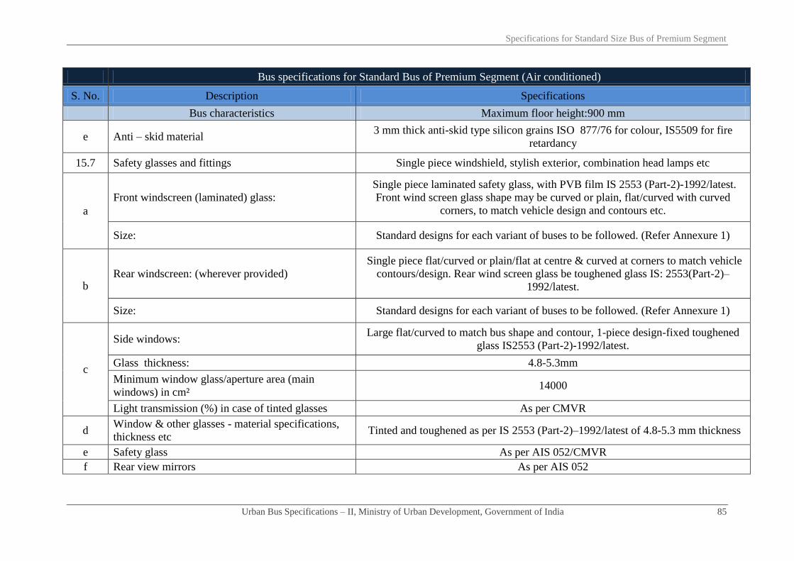
Specifications for Standard Size Bus of Premium Segment
Urban Bus Specifications – II, Ministry of Urban Development, Government of India 85
Bus specifications for Standard Bus of Premium Segment (Air conditioned)
S. No. Description Specifications
Bus characteristics Maximum floor height:900 mm
e Anti – skid material 3 mm thick anti-skid type silicon grains ISO 877/76 for colour, IS5509 for fire
retardancy
15.7 Safety glasses and fittings Single piece windshield, stylish exterior, combination head lamps etc
a
Front windscreen (laminated) glass:
Single piece laminated safety glass, with PVB film IS 2553 (Part-2)-1992/latest.
Front wind screen glass shape may be curved or plain, flat/curved with curved
corners, to match vehicle design and contours etc.
Size: Standard designs for each variant of buses to be followed. (Refer Annexure 1)
b Rear windscreen: (wherever provided)
Single piece flat/curved or plain/flat at centre & curved at corners to match vehicle
contours/design. Rear wind screen glass be toughened glass IS: 2553(Part-2)–
1992/latest.
Size: Standard designs for each variant of buses to be followed. (Refer Annexure 1)
c
Side windows: Large flat/curved to match bus shape and contour, 1-piece design-fixed toughened
glass IS2553 (Part-2)-1992/latest.
Glass thickness: 4.8-5.3mm
Minimum window glass/aperture area (main
windows) in cm² 14000
Light transmission (%) in case of tinted glasses As per CMVR
d Window & other glasses - material specifications,
thickness etc Tinted and toughened as per IS 2553 (Part-2)–1992/latest of 4.8-5.3 mm thickness
e Safety glass As per AIS 052/CMVR
f Rear view mirrors As per AIS 052

Specifications for Standard Size Bus of Premium Segment
Urban Bus Specifications – II, Ministry of Urban Development, Government of India 86
Bus specifications for Standard Bus of Premium Segment (Air conditioned)
S. No. Description Specifications
Bus characteristics Maximum floor height:900 mm
15.8 Seating and gangway etc for ACX buses generally
as per AIS 052
Ergonomically designed seats with soft cushion head seats rest, spacious gangway
etc.
15.8.1 Passenger seating’s for ACX type-1 buses As per AIS 052
a Seat layout in the low floor area 2x2
b Seat layout in the higher floor area 2x2
c Seat area/seat space per Passenger (width*depth)
mm as per AIS 052 450*450
d Seat pitch - minimum: mm as per AIS 052 750
e
Minimum backrest height- from floor to top of
seat/headrest 1100 mm from floor as per AIS 052
Seat base height- distance from floor to horizontal
front upper surface of seat cushion mm As per AIS 052
f Torso angle Minimum 15⁰ with option of reclining adjustable seats
g
Passenger seats with high back rest, contoured to
suit human body, padded and provided with head
rest
√
h Seat materials Cushioned seats with polyurethane foam as per IS15961-2002.
i Seat frame structure material where required Frame structure of ERW steel or aluminium tubes/sheets/formed sections
j Free height over seating position mm More than 900
Seat base height As per AIS 052

Specifications for Standard Size Bus of Premium Segment
Urban Bus Specifications – II, Ministry of Urban Development, Government of India 87
Bus specifications for Standard Bus of Premium Segment (Air conditioned)
S. No. Description Specifications
Bus characteristics Maximum floor height:900 mm
k Clearance space for seated Passenger facing
partition mm As per AIS 052
l
Seat back/Pad material/thickness: Polyurethane foam IS15061:2002, 50± 5 mm
Type Suitably moulded/fabricated and padded with > 50 mm foam with cloth upholstery
Upholstery Pile fabric/jekard 0.7-1.0 mm thickness
m Area for seated passengers (sq.mm) 450*450
n Area for standee passengers (sq.mm) As per bus code
o Number of seats including one for wheel chair 32 - 34
p Number of standees (calculation as per AIS 052) As per AIS 052
q Sitting/Standing Ratio Not required
r Headrest Required
s Seats side facing location Not suggested except on wheel arches
t Seat arm As per AIS 052
u Magazine pouch Required
v Individual seat row fans Required if ventilation provisions are inadequate in the event of AC failures
w Reading lights individual Required
x Seat back rest Reclining
y Seat belts & their anchorage Not necessary except diver seat & wheel chair (performance etc. as per AIS 052)
z Performance & strength requirements of driver &
passenger seats As per AIS 052
15.8.2 Gangway: Minimum 600 mm
a Minimum interior head room (centre line of
gangway) mm 1900 including that in the rear overhang area.

Specifications for Standard Size Bus of Premium Segment
Urban Bus Specifications – II, Ministry of Urban Development, Government of India 88
Bus specifications for Standard Bus of Premium Segment (Air conditioned)
S. No. Description Specifications
Bus characteristics Maximum floor height:900 mm
i At front axle: As per AIS 052
ii At rear axle: As per AIS 052
iii Other areas As per AIS 052
b
Gangway width (mm) from gates to longitudinal
space between seats (access to service doors) Minimum 600 mm
Gangway width (mm) in longitudinal space
between seats Minimum 600 mm
Gangway width (mm) in longitudinal space
between seats (rear of rear edge of the rear door in
rear engine bus)
Minimum 600 mm
c
Slope of the gangway in type I ACX bus As per AIS 052
General
Gangway slope in zone rearward of a transverse
vertical plane situated 1500 mm forward of the
centre line of the rear axle
As per AIS 052
15.9
Driver’s work place/cabin/seat etc As per AIS 052
Driver work place/cabin provided with more
privacy, safety and easy access to controls and inter
alia equipped with:
State of art driver cockpit station.
a Reverse gear camera As per ITS specifications
b Door cameras As per ITS specifications
c Lights control √
d Fans and/or other means of ventilation & air
circulation in the event of failure of AC √

Specifications for Standard Size Bus of Premium Segment
Urban Bus Specifications – II, Ministry of Urban Development, Government of India 89
Bus specifications for Standard Bus of Premium Segment (Air conditioned)
S. No. Description Specifications
Bus characteristics Maximum floor height:900 mm
e Driver’s seat generally as per AIS 023 and duly
equipped with As per AIS 023 & AIS 052
i Three way seat adjustments facility and controls √
ii Air suspension system √
15.10 Corrosion prevention & painting Corrosion prevention treatment/painting for structural members/components,
assembled structure, panels etc
a
Corrosion prevention treatment
All materials & joints would withstand a two weeks (336 hours) salt spray test in
accordance with ASTM procedure B117 with no structural detrimental effect to
normally visible surfaces & no weight loss of over 1%. Other details As per AIS 052
Internal surfaces of structural members As above
External surfaces of structural members As above for internal surfaces of tubular structural members corrosion prevention
After drilling holes/welding
As above for corrosion prevention if any riveting and or welding operations carried
out after treatment , etc,
corrosion free guaranteed life of bus items/structure in years/km
Inter metallic galvanic corrosion prevention Required
b Primer coating Suitable specification and performance
c Painting
PU paint panel etch primer, PU primer surface, PU top coat BIS 13213:1991 or
latest/international standard as applicable for exterior painting including interior
wherever required. shades–IS 5-1978 (or latest) class-A2
16 Electricals
16.1 Electrical Cables
BIS marked, copper conductors with fire retardant as per IS/ISO:6722:2006 as per
appropriate class. conductor x-sec varying as per circuit requirements, minimum
cross-section 0.5 sq mm. quality marking may also be as per equivalent or better
European, Japanese, US standards

Specifications for Standard Size Bus of Premium Segment
Urban Bus Specifications – II, Ministry of Urban Development, Government of India 90
Bus specifications for Standard Bus of Premium Segment (Air conditioned)
S. No. Description Specifications
Bus characteristics Maximum floor height:900 mm
16.2 Conductor cross section As above and suitable to carry rated current (Japanese Auto Standard JASO D0609-
75 AV)
16.3 Safety requirements of electrical As per AIS 052
a Fuse As per AIS 052 - fuse of rated current 1.5 times the load current of electrical
equipment. Necessary in every electrical circuit
b Isolation switches for electrical circuits where RMS
value of voltage exceeds 100 volts As per AIS 052. Isolation switch required for each such circuit
c Location of cables away from heat sources As per AIS 052- required for each such circuit
d Type approval of circuit diagram as per standards
related to electric equipments/wiring As per AIS 052 - required for all items
e Battery cut - off switch (isolator switch) Heavy-duty type capable of carrying & interrupting total circuit load.1 each near
battery/driver
16.4 Wind screen wiping & washing system, demister
etc:
Pantograph type electrically operated with two wiper arms & blades; wiper motor
heavy-duty steel body with minimum 2-speed operation; wiping system as per
CMVR/BIS 7827 Part-1, 2, 3 (Sec.1 & 2)/latest. As per AIS 011
a Wiper motor Variable speed with time delay relay as per IS011.20-24 cycles/sec, 24 V*150W
minimum.
b Wiper arm/blade Pantograph type. AIS 019/AIS011
c Wind screen washing system √
d Capacity of washing system tank litres minimum 10
16.5 Driver Cabin Fan 1 number, 200 mm fan. As per provision of CMVR, matching interiors
16.6 Lighting - internal & external and illumination As per AIS 052
16.7 Illumination requirements/performance of:

Specifications for Standard Size Bus of Premium Segment
Urban Bus Specifications – II, Ministry of Urban Development, Government of India 91
Bus specifications for Standard Bus of Premium Segment (Air conditioned)
S. No. Description Specifications
Bus characteristics Maximum floor height:900 mm
a Dash board tell tale lighting/control lighting As per AIS 052 & bulbs tested for photometry as per IS 1606:1996
b Cabin lighting- luminous flux of all lamps for cabin
lighting As per AIS 052 with illumination level of ≥ 100 lux & ≤ 200 lux
c Passenger area lighting -luminous flux of all lamps
for Passenger area lighting As per AIS 052 with illumination level of ≥ 100 lux and ≤ 150 lux
17 ITS As specified separately under ITS specifications
18 Safety related items
18.1 Driver seat belt & anchorage duly type approved ELR recoil type, 3 point mounting as per CMVR & bus code. Conforming to AIS
005 & AIS 015
18.2
Passengers seat belt
Not necessary except diver seat & wheel chair (performance etc. as per AIS 052) Number
18.3 Driver/Passenger/Wheelchair seatbelt anchorage
18.4 Fire extinguisher Dry chemical powder type GSR– 853 (E) dated 19.11.2000 (or latest)/As per AIS
052, 2 kg each, ISI Marked
18.5 First aid box 1 Number, as per provision of CMVR
18.6 Handrails Minimum length*diameter*height above
floor: mm
Colour contrasting and slip resistant of aluminium tubing. 32 mm diameter, 3 mm
thick.
18.7 Handholds Colour contrasting and slip resistant. 2 to 4 Numbers. Hand holds per bay. Other
details as per AIS 052
18.8 Stanchions Vertically fitted, aluminium tubing with Colour contrasting and slip resistant. 40
mm diameter & 3.15 mm thick. Other details as per AIS 052

Specifications for Standard Size Bus of Premium Segment
Urban Bus Specifications – II, Ministry of Urban Development, Government of India 92
Bus specifications for Standard Bus of Premium Segment (Air conditioned)
S. No. Description Specifications
Bus characteristics Maximum floor height:900 mm
18.9 Bells for Passenger convenience High visibility bell pushes shall be fitted at a height of 1.2 meter on all alternate
stanchions. These would assist PwDs
18.10 Entrance/Exit Guard/Step well guard: 800 mm minimum height extending ≥ 100mm more than centre line of sitting
position of the Passenger.
18.11 Emergency exit doors, warning devices etc: As per AIS 052/CMVR
18.12 Front/Rear door, step well lights, door open sign Incandescent bulb/LED as per AIS 008
18.13 Mirrors right/left side exterior/interior Convex As per AIS 001 & 002. Interior with double curvature
18.14 Towing device front/rear Heavy duty 1.2 times (minimum) the kerb weight of the bus within 30
o of the
longitudinal axis of the bus. As per CMVR & IS 9760 - Ring Type
18.15 Warning triangle As per AIS 052/CMVR
18.16 Fog lighting As per AIS 052/CMVR
18.17 Bumpers - front and rear
Both made of steel or impact resistant polymer or combination of both meeting
requirement of an energy absorbing system
Impact strength for bumpers Meet requirements of Para 6.3.1 of AIS 052
18.18 Gas leak detection system for CNG fuelled engines √ √
18.19 Fire detection system √ √
18.20 Fire suppression system √ √
19 Miscellaneous items/requirements
19.1 Windows
a Type of window Large tinted window panes for ACX bus
b Minimum height of window aperture (clear vision) ≥ 1200 mm in type I -ACX
c Minimum height of upper edge of window aperture
from bus floor As per AIS 052

Specifications for Standard Size Bus of Premium Segment
Urban Bus Specifications – II, Ministry of Urban Development, Government of India 93
Bus specifications for Standard Bus of Premium Segment (Air conditioned)
S. No. Description Specifications
Bus characteristics Maximum floor height:900 mm
d Minimum width of windows (clear vision zone) As per AIS 052
19.2 Cabin luggage carrier (CLC) As per AIS 052
a Positioning of CLC
i Width from side wall (mm) 250
ii Height from roof (mm) 200
b Design & material "ABS (acrylonitrile butadiene styrene) ASTM-BS368/better or similar to that in
Passenger aero planes
c Additional provisions at the underside of CLC √
i Individual seat reading light At the discretion of purchaser. Bus should be enabled
ii Individually adjustable air conditioning knob At the discretion of purchaser. Bus should be enabled
iii Call button At the discretion of purchaser. Bus should be enabled
19.3 Passenger entertainment and other miscellaneous
items
a Touch screen setting type TV for individual seats At the discretion of purchaser. Bus should be enabled
b Audio ports at arm rest for TV and piped music At the discretion of purchaser. Bus should be enabled
c Head phone (replaceable loose item on demand) At the discretion of purchaser. Bus should be enabled
d Folding table for each seat √
e Magazine pouch √
f Adjustable foot rest At the discretion of purchaser. Bus should be enabled
g Back rest adjustment knob in case of reclining seats √
h Power ports on each seat to facilitate use of laptop,
MP3 player, USB etc √
i Cluster of mobile phone charging points √

Specifications for Standard Size Bus of Premium Segment
Urban Bus Specifications – II, Ministry of Urban Development, Government of India 94
Bus specifications for Standard Bus of Premium Segment (Air conditioned)
S. No. Description Specifications
Bus characteristics Maximum floor height:900 mm
20 Air conditioning system - operational
conditions/other requirements etc.
20.1 Specifications a) For up to 42°C of saloon temperature and b) For > 42°C of saloon temperature
20.2 Target results a) 23+/- 1°C (for all temperature ranges)
b) Minimum average air velocity at air vent is 4.5 m/s
20.3 Apparatus Lab condition and heating chamber
20.4 Procedure
1. Soak for 1 hour
2. At 2000 rpm
3.Upto 42°C: pull down time 30 minutes (maximum) (for more than 42°C of saloon
temperature, pull down time within 40 minutes (maximum))
4. Thermocouple to be placed over place minimum 20 numbers. at nose level
20.5
Air curtains on entry/exit gates to avoid loss/gain of
heat and or cool air when doors are frequently
opened for boarding/alighting of Passenger with
minimum air flow of 1000±50 m³/hr at each gate
Optional
20.6 Individual seat air flow adjustment system Required
20.7 Air conditioning system in driver work place As in saloon
21 Noise, vibration and harshness (NVH) levels
(interior)
21.1
Maximum noise levels inside the saloon
(irrespective of AC, non-AC/fuel type/engine
location)-test procedure as per AIS 020
≤ 75 Db(A) (to be achieved a maximum noise level of 72 Db(A) from 1st April 2015
onwards)
21.2 Vibration levels

Specifications for Standard Size Bus of Premium Segment
Urban Bus Specifications – II, Ministry of Urban Development, Government of India 95
Bus specifications for Standard Bus of Premium Segment (Air conditioned)
S. No. Description Specifications
Bus characteristics Maximum floor height:900 mm
a Vibration levels at driver/Passenger seats
(meter/sec²) ≤ 0.5
b Vibration level in gangway (meter/sec²) ≤ 1
21.3
Harshness levels when measured under city driving
conditions on city roads with pot holes and speed
breakers, etc
a Noise level in saloon from drive axle, etc Nil
b Dominant frequencies to fall outside the ranges of 0.5-1 Hz, 5-7 Hz and 18-20 Hz
c Transient vibration level in seating area maximum 1g
d Transient vibration level at driver seat maximum 0.1g
22 Life cycle requirements of bus (whichever is
earlier) 15 years or 12,00,000 km

Chapter - 07
Specifications for Midi bus of Premium
segment

Specifications for Midi Bus of Premium Segment
Urban Bus Specifications – II, Ministry of Urban Development, Government of India 96
Bus specifications for Midi Bus of Premium Segment (Air conditioned)
S. No. Description Specifications
Bus characteristics Maximum floor height:900 mm
Bus floor heights
As per AIS 052 (this segment of buses are envisaged to be more comfortable for
seating passengers with lesser standees). However all buses to be delivered after 1st
April 2015 will follow the same definition as in the case of non-premium buses) i.e.
“low floor area shall not be less than 50% of the total saloon area (excluding front
wheel boxes and driver’s cab) and shall not be ramped in the longitudinal plane”
1 Propulsion system Internal combustion engine, electrical, hybrid, fuel cell
2 Fuels-options Diesel/CNG/ULSD/hydrogen
3 Engine
3.1 Fuel recommended Fuel to be compatible with propulsion system
3.2 Engine HP sufficient to provide:
a Rated performance at GVW in a stop/start urban
operations Maximum vehicle speed of up to 75 kmph bus GVW
b Acceleration (meter/sec²) complemented with
minimum 1000 Nm torque 0.9
c Attain bus speed of 0-30 kmph 9.0 seconds
d Max speed ≤ 75 kmph
e Grade ability from stop at 1.5 GVW (%) 17
f Rated HP/torque preferably at lower rpm range HP rating designed to provide rated torque of minimum 1000 Nm (under full load)
preferably at lower rpm range.
3.3
Maximum fuel efficiency kmpl or kmpkg. Vehicle
Manufacturer to specify fuel efficiency in terms of
kmpl or kmpkg under standard 13 mode urban
operating cycle and rated loading. While tendering,
purchaser may take into account the higher weight age
for more fuel efficient vehicle
√
3.4 Emission norms BS III/BS IV or latest as applicable

Specifications for Midi Bus of Premium Segment
Urban Bus Specifications – II, Ministry of Urban Development, Government of India 97
Bus specifications for Midi Bus of Premium Segment (Air conditioned)
S. No. Description Specifications
Bus characteristics Maximum floor height:900 mm
3.5 Electronic engine management (EMS) system with
following provisions amongst others:
Full electronic management of engine including on-board diagnostic and driver
alerts e.g. engine oil pressure, engine coolant temperature, engine speed in RPM,
vehicle speed, diagnostic details message (engine specific)
a Fault tracing and diagnostics √
b Information generation about driver and vehicle
performance as specified as part of ITS specifications √
3.5.1 Typical EMS parameters √
a Fuel feed & fuel delivery system status related to: √
i Feed pump pressure √
ii Fuel delivery pressure √
iii Booster pressure and temperature √
b Coolant Status related to: √
i Coolant level √
ii Coolant temperature √
iii Coolant pressure √
c Engine oil status related to: √
i Oil level √
ii Oil temperature √
iii Oil pressure √
d Accelerator pedal position √
e Water in fuel indicator √
f Injector status √
g Engine position timing sensor √
h Engine speed sensor √
i Control and information links √

Specifications for Midi Bus of Premium Segment
Urban Bus Specifications – II, Ministry of Urban Development, Government of India 98
Bus specifications for Midi Bus of Premium Segment (Air conditioned)
S. No. Description Specifications
Bus characteristics Maximum floor height:900 mm
i SAE J1939 control link √
ii SAE J1587 / J1708 Information link √
3.6 Engine operational requirements √
3.7 Engine location Rear
3.8
Transmission-heavy duty-
Automatic with torque convertor and in-built retarder -
hydrodynamic type. Neutral during stops. Reduced
engine load at stops (NBS)
√
4 Operational safety - transmission related
4.1 Reverse gear engagement
Transmission system to be fitted with a mechanism which makes it possible to
engage reverse gear only when vehicle is stationary (applicable for automatic &
automatic manual transmission)
4.2 An interlock to prevent the movement of bus when
doors opened √
4.3 Drive shaft lubrication for life √
5 Clutch Not applicable
6 Steering system Hydraulic power steering with height and angle adjustments provision. Adjustable
steering column.
7 Suspension system Fully pneumatic complete with ECAS/electronic management and control systems
7.1 Front Air bellows - 2 numbers
7.2 Rear Air bellows – 2/4 numbers
7.3 Kneeling (mm) 60 mm entry/exit side severally & collectively
7.4 An interlock to prevent movement of bus when
kneeled/kneeling √ √

Specifications for Midi Bus of Premium Segment
Urban Bus Specifications – II, Ministry of Urban Development, Government of India 99
Bus specifications for Midi Bus of Premium Segment (Air conditioned)
S. No. Description Specifications
Bus characteristics Maximum floor height:900 mm
7.5 Anti roll bars/stabilizers1 Both front and rear
7.6 Shock absorbers Hydraulic double acting 2 at front & 2/4 at rear
7.7 Controls Electronically controlled air suspension or superior system
a Electronic control suspension system for: √
b Controlling floor level √
c Enhancing comfort by absorbing shocks in case of
road irregularities √
d Uniform spring rate in all loading conditions √
e Self correction of bellow height to: √
i Help protect driveline angularity related problems √
ii Counter road unevenness √
iii Monitor bellow failures √
iv Provide passenger comfort √
8 Braking System
Dual circuit full air brakes, with disc type arrangement for front and rear brakes.
Full pneumatic electronically controlled disc brakes with brake blending and
rollback prevention system. Graduated hand controlled, spring actuated parking
brakes acting on rear wheels.
8.1
Anti skid anti brake locking system (ABS) necessary
for urban driving cycle: i) involving high levels of
unexpected braking requirements, ii) calling for
excessive panic braking particularly in rainy season.
iii) Requiring enhanced manoeuvrability, smooth
stopping and low wear and tear of involved
components.
√
1 Optional in case of independent suspension

Specifications for Midi Bus of Premium Segment
Urban Bus Specifications – II, Ministry of Urban Development, Government of India 100
Bus specifications for Midi Bus of Premium Segment (Air conditioned)
S. No. Description Specifications
Bus characteristics Maximum floor height:900 mm
8.2
Electronic braking control system (EBS) for uniform
distribution of braking force on all wheels,
contributing to smooth braking, optimizing braking
with minimal pedal force thereby reducing driver
fatigue.
√
8.3 Electronic monitoring of brakes
a Brake pad condition √
b Brake pad temperature condition √
9 Electrical system 24 volt DC
9.1 Batteries:
Low maintenance type lead acid batteries for 24 V system- performances as per
BIS: 14257-1995 (latest). 2*12V batteries of 180 Ah capacity. Maintenance free
batteries preferred
9.2 Self starter 24V
9.3 Alternator 24V- another alternator of similar capacity for AC.
9.4 Electrical wiring & controls- type As specified separately under ITS specifications
10 Speed limiting device (optional) Electronic type duly approved/certified as per AIS: 018/2001 or latest, tamper proof
and be adjusted to applicable speed limit
11 Tyres Steel radial tube-less. Size and performance as per CMVR
12 Fuel tank
On-board fuel storage capacity adequate for bus operation of over 250 km between
consecutive fillings
Fuel tank location Optional
13 Bus characteristics
13.1 Bus dimensions mm
a Overall length (over body excluding bumper) in mm ≤ 9400
b Overall width (sole bar/floor level- extreme points) in
mm 2600 (maximum)

Specifications for Midi Bus of Premium Segment
Urban Bus Specifications – II, Ministry of Urban Development, Government of India 101
Bus specifications for Midi Bus of Premium Segment (Air conditioned)
S. No. Description Specifications
Bus characteristics Maximum floor height:900 mm
c Overall height (unladen)-(at extreme point ) 3800(maximum)
d Wheel-base ≤ 5000
e Front overhang in mm As per CMVR
f Rear overhang As per CMVR
13.2 Turning circle radius (mm)-maximum 10 meters As per CMVR
13.3 Floor height above ground (mm) ≤ 900
13.4 Clearances (mm)
a Axle clearance (mm) Minimum190
b Minimum ground clearance (un-kneeled) at GVW Within the wheelbase not less than 240 mm.
13.5 Angles (degrees)
a Angle of approach (unladen) ≥ 8.0⁰
b Angle of departure (unladen) ≥ 8.5⁰
c Ramp over angle (half of break-over angle) ≥ 4.8⁰
14 Bus body
14.1 Location of gates Location on near side
14.2 Type of doors Swing in/out type
a Operating mechanism Electro pneumatically controlled
b Opening closing time in seconds per operation ≤ 4
c Positions of door controls ensuring display of
open/close status on dash board
On dashboard, as also inside & outside of doors for emergency operation and at
stanchions for Passenger access
d
Passenger safety system - allowing bus motion on
doors closing and doors opening only when the bus is
stopped
Mandatory
14.3 Front service doors - near side: √
a Door aperture (without flaps) in mm As per AIS 052

Specifications for Midi Bus of Premium Segment
Urban Bus Specifications – II, Ministry of Urban Development, Government of India 102
Bus specifications for Midi Bus of Premium Segment (Air conditioned)
S. No. Description Specifications
Bus characteristics Maximum floor height:900 mm
b Clear door width (fully opened) in mm As per AIS 052
c Door height in mm As per AIS 052
d Positioning front service gate As per AIS 052
e Number of gates 1
14.4 Rear service doors (near side): Optional
a Door aperture (without flaps) in mm As per AIS 052
b Clear door width (fully opened) in mm As per AIS 052
c Door height in mm As per AIS 052
d Positioning rear door Preferably rear edge of gate 1500 mm ahead of central line of rear axle or front edge
of gate 1500 mm behind central line of rear axle
e Number of gates 1
14.5 Maximum first step height(mm) from ground -
unladen & un-kneeled position in buses with:
a Stepped type entry 400
14.6 Maximum height (mm) of other steps
a if door ahead of rear axle 250
b if door behind rear axle NA
14.7 Ramp for wheel chair at the gates
Sunken type wrap over (manually
operated) ramp, for wheel chair of PwDs,
fitted on floor at gate (preferably at front
gate) in front of PwD seat anchorage. Suitable design mechanism for >
400mm floor ht considering that floor
level of bus stops are at 400mm a Dimensions Width ≥ 900 mm
b Material Aluminium alloy with anti-slip coating
c Load carrying capacity > 300 kg

Specifications for Midi Bus of Premium Segment
Urban Bus Specifications – II, Ministry of Urban Development, Government of India 103
Bus specifications for Midi Bus of Premium Segment (Air conditioned)
S. No. Description Specifications
Bus characteristics Maximum floor height:900 mm
d Device to prevent the wheel chair roll off the sides
when the length exceeds 1200mm √
e Device to lock wrapped up ramp √
f Kneel ramp control Kneeling arrangement for kneeling on left side severally and combined. Kneeling
up to 60mm
g Requirement for passenger with limited mobility √
h Wheel chair anchoring- minimum for one wheel chair √
i Priority seats- minimum 2 seats √
j Stop request- on every pillar √
k Place to keep PwD assists like cane, etc √
l Colour contrasting/other guidance for persons with
visual deficiencies √
m Any other provisions to meet requirement of
disabilities Act 1995 √
14.8 Emergency doors/exits or apertures (numbers) As per AIS 052
Dimensions mm As per AIS 052
14.9 Door closing requirements for bus movement - Bus could move only after door closing completed
a
Power operated service door - construction & control
system of a power operated service door be such that a
Passenger is unlikely to be injured/trapped between
the doors while closing.
As per AIS 052
b Door components As per AIS 052
c Door locks/locking systems/door retention items As per AIS 052
d Door hinges As per AIS 052

Specifications for Midi Bus of Premium Segment
Urban Bus Specifications – II, Ministry of Urban Development, Government of India 104
Bus specifications for Midi Bus of Premium Segment (Air conditioned)
S. No. Description Specifications
Bus characteristics Maximum floor height:900 mm
15 Bus body
15.1 Design type approval
a
Design type approval- all bus body structures &
structural aggregates be designed to fulfil the loading,
operating & performance parameters using finite
element analysis or any other analytic technique for:
Required Strength
Stiffness
Structural Stability
Vibration
Safety
15.2 Structural performance
a Bus structure to meet requirements of:
i Body structure strength test-
each type of vehicle be subjected to roll over test on
complete vehicle/specified representative section
thereof or to an alternate method approved by the test
agency
As per AIS 052
ii Stability As per AIS 052
iii Deflection √
iv Vibrations √
v Roll over protection √
vi Safety √

Specifications for Midi Bus of Premium Segment
Urban Bus Specifications – II, Ministry of Urban Development, Government of India 105
Bus specifications for Midi Bus of Premium Segment (Air conditioned)
S. No. Description Specifications
Bus characteristics Maximum floor height:900 mm
vii
Joint strength- body panel joints meet requirements of
holding the joined panel when subjected to force of
60% of tensile strength of weakest joined body panel.
As per AIS 052
b Various loads:
i
Normal loads (static) = Number of Passenger*weight
of Passenger (68 Kgs.) + Passenger luggage weight (7
Kgs). (Besides the vehicle related loads).
√
ii
Bump loads: # Bump height = As per relevant
BIS/Indian Road Congress guidelines. # Case I:
single wheel on bump/pot hole. # Case II: diagonally
opposite wheels on Bump/Pot hole. # Case III: both
wheels (front & rear) on bump/pot hole.
√
iii Braking loads: 0.6g (applied together). Horizontal =
0.6g load, Vertical = 1g load √
c Bus body structure evaluation As under
i Physical testing or As per AIS 052
ii Finite element method As per AIS 052
d Required performance values/data (minimum) for
above load conditions: As under
i Strength (factor of safety) (tolerance -10%) ≥ 3 i.e. design stress ≥ 1/3rd
of yield stress
ii Stiffness (deflection) mm 5mm
iii Vibrations (lowest natural frequency) hertz 5Hz

Specifications for Midi Bus of Premium Segment
Urban Bus Specifications – II, Ministry of Urban Development, Government of India 106
Bus specifications for Midi Bus of Premium Segment (Air conditioned)
S. No. Description Specifications
Bus characteristics Maximum floor height:900 mm
iv
Roll over tests with the bus rolling from ground level
instead of a raised platform. Angular velocity should
not exceed 5 degrees/sec. All other procedure as per
AIS031 (i) Unstable position should not occur before 35⁰. (ii) No part of structure intrudes
into residual space. 1 Bus tilted to its unstable position
2. Bus allowed falling freely under gravity from this
position.
3. GVW of the bus to be considered
v
4. Energy absorbed by the structure {ER =Reference
energy-- potential energy of the bus in its (unstable)
equilibrium position). ER = M*g*h Where M=
Effective weight of the bus, g = Acceleration due to
gravity, h= height of C.G. above ground level in
(unstable) equilibrium position.}.
0.75 ER
vi Buckling factor ≥ 4
15.3 Bus structure- materials specifications etc
a Super structure Material to be decided by the manufacturer OR as per the tender specifications
issues by purchaser. Other requirements as per bus body code. Material should fulfil
strength etc. requirements indicated above b Under structure:
c Panelling
i Roof panelling: interior Material to be decided by the manufacturer OR as per the tender specifications
issues by purchaser. Other requirements as per bus body code. Material should fulfil
strength etc. requirements indicated above
ii Roof panelling: exterior
iii Side panelling: interior
iv Other side panels:

Specifications for Midi Bus of Premium Segment
Urban Bus Specifications – II, Ministry of Urban Development, Government of India 107
Bus specifications for Midi Bus of Premium Segment (Air conditioned)
S. No. Description Specifications
Bus characteristics Maximum floor height:900 mm
v Stretch panel: Exterior side panels of stretched steel
sheet at different waist levels along length of the bus
vi Skirt panel
vii Front end interior
viii Front end exterior
ix Rear end interior
x Rear end exterior
15.4 Insulation Material to be decided by the manufacturer subject to meeting requirement of flame
retardancy, fire proofing and non-in flammability as per applicable standards
a Roof structure Flame retardant/non flammable-- polyurethane/glass wool IS 15061or latest of
density 40 Kg/m3 minimum.
b Engine compartment Fire retardant preferably ceramic fibre 128 kg/m3
15.5 Aluminium extruded sections for:
a Rub rail
Aluminium extrusion IS 733/1983 or better
b Decorative moulding
c Wire cover
d Wearing strip
e Foot step edging
f Panel beading
g Window frame
h Roof grab rail brackets
15.6 Floor type/Materials etc
a Type of floor Flat except at wheel arches in the low floor area of bus- seats may be located over
the wheel arches

Specifications for Midi Bus of Premium Segment
Urban Bus Specifications – II, Ministry of Urban Development, Government of India 108
Bus specifications for Midi Bus of Premium Segment (Air conditioned)
S. No. Description Specifications
Bus characteristics Maximum floor height:900 mm
b Steps on floor
For 400 mm floor height: no steps except
those necessary for the rear high floor
area
For higher floor height: steps in the low
floor area either at gates or across the
floor. Steps may be provided as
necessary on high floor in the rear side
c Maximum floor slope 6 %
d Floor surface material
12 mm thickness phenolic resin bonded densified laminated compressed wooden
floor board (both side plain surface) having density of 1.2 gms/cc conforming to IS
3513 (Part-3): type VI 1989 or latest. The flooring should also be boiling water
resistant as for marine board BIS 710-1976/ latest and fire retardant as per BIS
5509-2000 (IS 15061:2002)
e Anti – skid material 3 mm thick anti-skid type silicon grains ISO 877/76 for colour, IS5509 for fire
retardancy
15.7 Safety glasses and fittings: Single piece windshield, stylish exterior, combination head lamps etc
a Front windscreen (laminated) glass:
Single piece laminated safety glass, with PVB film IS 2553 (Part-2)-1992/latest.
Front wind screen glass shape may be curved or plain, flat with curved corners, to
match vehicle design and contours etc.
Size: Standard designs for each variant of buses to be followed. (Refer Annexure 1)
b Rear windscreen: (wherever provided)
Single piece curved or plain/flat/curved at centre & curved at corners to match
vehicle contours/design. Rear wind screen glass be toughened glass IS 2553(Part-
2)–1992/latest.
Size: Standard designs for each variant of buses to be followed. (Refer Annexure 1)
c Side windows:
Large flat/curved to match bus shape and contour, 1-piece design-fixed toughened
glass IS2553 (Part-2)-1992/latest.
Glass thickness: 4.8-5.3mm

Specifications for Midi Bus of Premium Segment
Urban Bus Specifications – II, Ministry of Urban Development, Government of India 109
Bus specifications for Midi Bus of Premium Segment (Air conditioned)
S. No. Description Specifications
Bus characteristics Maximum floor height:900 mm
Minimum window glass/aperture area (main windows)
cm² >10000
Light transmission (%) in case of tinted glasses As per CMVR
d Window & other glasses - material specs, thickness
etc Tinted and toughened as per IS 2553 (Part-2)–1992/latest of 4.8-5.3 mm thickness
e Safety glass As per bus code AIS 052/CMVR
f Rear view mirrors As per bus code AIS 052
15.8 Seating and gangway etc for ACX buses generally as
per AIS 052
Ergonomically designed seats with soft cushion head seats rest, spacious gangway
etc.
15.8.1 Passenger seating’s for ACX type-1 buses As per bus code AIS 052
a Seat layout in the low floor area 2x2
b Seat layout in the higher floor area 2x2
c Seat area/seat space per Passenger (width*depth) mm
as per AIS 052 450*450
d Seat pitch - minimum: mm as per AIS 052 750
e
Minimum backrest height -from floor to top of
seat/headrest 1100 mm from floor as per AIS 052
Seat base height- distance from floor to horizontal
front upper surface of seat cushion mm As per AIS 052
f Torso angle Minimum 15⁰ with option of reclining adjustable seats
g Passenger seats with high back rest, contoured to suit
human body, padded and provided with head rest √
h Seat materials Cushioned seats with polyurethane foam as per IS15961-2002.
i Seat frame structure material where required Frame structure of ERW steel or aluminium tubes/sheets/formed sections
j Free height over seating position mm More than 900

Specifications for Midi Bus of Premium Segment
Urban Bus Specifications – II, Ministry of Urban Development, Government of India 110
Bus specifications for Midi Bus of Premium Segment (Air conditioned)
S. No. Description Specifications
Bus characteristics Maximum floor height:900 mm
Seat base height As per AIS 052
k Clearance space for seated Passenger facing partition
mm As per AIS 052
l
Seat back/Pad material/thickness: Polyurethane foam IS15061:2002, 50± 5 mm
Type Suitably moulded/fabricated and padded with > 50 mm foam with cloth upholstery
Upholstery Pile fabric/jekard 0.7-1.0 mm thickness
m Area for seated passengers (sq.mm) 450*450
n Area for standee passengers (sq.mm) As per AIS 052
o Number of seats including one for wheel chair 23- 34
p Number of standees (calculation as per AIS 052) As per AIS 052
q Sitting/Standing ratio Not required
r Headrest Required
s Seats side facing location Not suggested except on wheel arches
t Seat arm As per AIS 052
u Magazine pouch Required
v Individual seat row fans Required if ventilation provisions are inadequate in the event of AC failures
w Reading lights individual Required
x Seat back rest Reclining
y Seat belts & their anchorage Not necessary except diver seat & wheel chair (performance etc. as per AIS 052)
z Performance & strength requirements of: √
i Driver seat (fully air suspended) AIS 023
ii Passenger seats AIS 023
15.8.2 Gangway: Minimum 600 mm
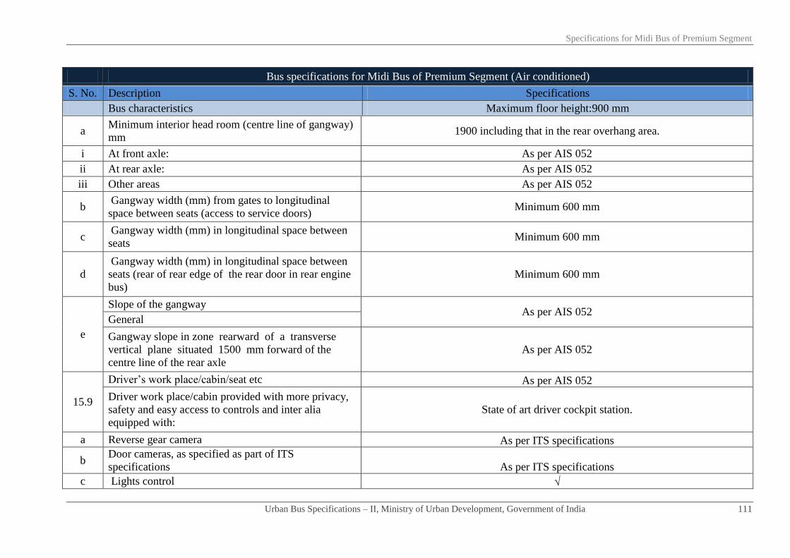
Specifications for Midi Bus of Premium Segment
Urban Bus Specifications – II, Ministry of Urban Development, Government of India 111
Bus specifications for Midi Bus of Premium Segment (Air conditioned)
S. No. Description Specifications
Bus characteristics Maximum floor height:900 mm
a Minimum interior head room (centre line of gangway)
mm 1900 including that in the rear overhang area.
i At front axle: As per AIS 052
ii At rear axle: As per AIS 052
iii Other areas As per AIS 052
b Gangway width (mm) from gates to longitudinal
space between seats (access to service doors) Minimum 600 mm
c Gangway width (mm) in longitudinal space between
seats Minimum 600 mm
d
Gangway width (mm) in longitudinal space between
seats (rear of rear edge of the rear door in rear engine
bus)
Minimum 600 mm
e
Slope of the gangway As per AIS 052
General
Gangway slope in zone rearward of a transverse
vertical plane situated 1500 mm forward of the
centre line of the rear axle
As per AIS 052
15.9
Driver’s work place/cabin/seat etc As per AIS 052
Driver work place/cabin provided with more privacy,
safety and easy access to controls and inter alia
equipped with:
State of art driver cockpit station.
a Reverse gear camera As per ITS specifications
b Door cameras, as specified as part of ITS
specifications As per ITS specifications
c Lights control √

Specifications for Midi Bus of Premium Segment
Urban Bus Specifications – II, Ministry of Urban Development, Government of India 112
Bus specifications for Midi Bus of Premium Segment (Air conditioned)
S. No. Description Specifications
Bus characteristics Maximum floor height:900 mm
d Fans and/or other means of ventilation & air
circulation in the event of failure of AC √
e Driver’s seat generally as per AIS 023 and duly
equipped with AIS 023 & AIS 052
i Three way seat adjustments facility and controls √
ii Air suspension system √
15.10 Corrosion prevention & painting Corrosion prevention treatment/painting for structural members/components,
assembled structure, panels etc
a
Corrosion prevention treatment
All materials & joints would withstand a two weeks (336 hours) salt spray test in
accordance with ASTM procedure B117 with no structural detrimental effect to
normally visible surfaces & no weight loss of over 1%. Other details as per AIS 052
Internal surfaces of structural members As above
External surfaces of structural members As above for internal surfaces of tubular structural members corrosion prevention
After drilling holes/welding
As above for corrosion prevention if any riveting and or welding operations carried
out after treatment , etc,
corrosion free guaranteed life of bus items/structure in years/km
Inter metallic galvanic corrosion prevention Required
b Primer coating Suitable specification and performance
c Painting
PU paint panel etch primer, PU primer surface, PU top coat BIS 13213:1991 or
latest/international standard as applicable for exterior painting including interior
wherever required. shades–IS 5-1978 (or latest) class-A2
16 Electricals
16.1 Electrical cables
BIS marked, copper conductors with fire retardant as per IS/ISO:6722:2006 as per
appropriate class. conductor x-sec varying as per circuit requirements, minimum
cross-section 0.5 sq mm. quality marking may also be as per equivalent or better
European, Japanese, US standards
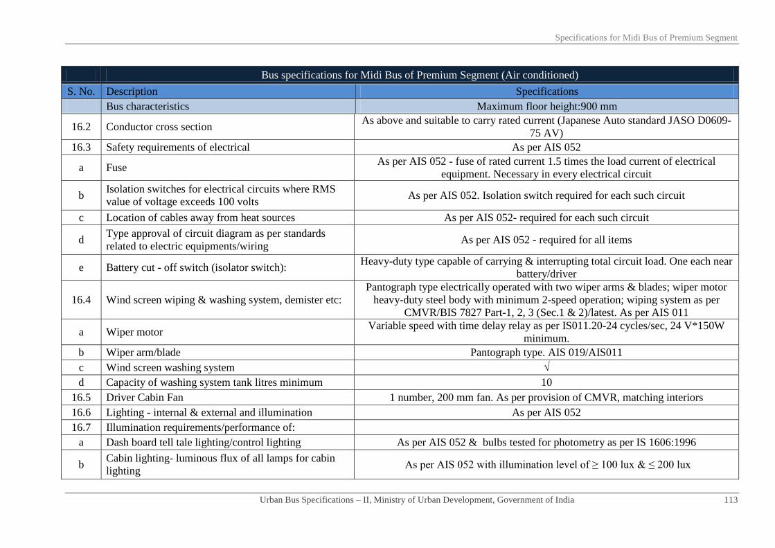
Specifications for Midi Bus of Premium Segment
Urban Bus Specifications – II, Ministry of Urban Development, Government of India 113
Bus specifications for Midi Bus of Premium Segment (Air conditioned)
S. No. Description Specifications
Bus characteristics Maximum floor height:900 mm
16.2 Conductor cross section As above and suitable to carry rated current (Japanese Auto standard JASO D0609-
75 AV)
16.3 Safety requirements of electrical As per AIS 052
a Fuse As per AIS 052 - fuse of rated current 1.5 times the load current of electrical
equipment. Necessary in every electrical circuit
b Isolation switches for electrical circuits where RMS
value of voltage exceeds 100 volts As per AIS 052. Isolation switch required for each such circuit
c Location of cables away from heat sources As per AIS 052- required for each such circuit
d Type approval of circuit diagram as per standards
related to electric equipments/wiring As per AIS 052 - required for all items
e Battery cut - off switch (isolator switch): Heavy-duty type capable of carrying & interrupting total circuit load. One each near
battery/driver
16.4 Wind screen wiping & washing system, demister etc:
Pantograph type electrically operated with two wiper arms & blades; wiper motor
heavy-duty steel body with minimum 2-speed operation; wiping system as per
CMVR/BIS 7827 Part-1, 2, 3 (Sec.1 & 2)/latest. As per AIS 011
a Wiper motor Variable speed with time delay relay as per IS011.20-24 cycles/sec, 24 V*150W
minimum.
b Wiper arm/blade Pantograph type. AIS 019/AIS011
c Wind screen washing system √
d Capacity of washing system tank litres minimum 10
16.5 Driver Cabin Fan 1 number, 200 mm fan. As per provision of CMVR, matching interiors
16.6 Lighting - internal & external and illumination As per AIS 052
16.7 Illumination requirements/performance of:
a Dash board tell tale lighting/control lighting As per AIS 052 & bulbs tested for photometry as per IS 1606:1996
b Cabin lighting- luminous flux of all lamps for cabin
lighting As per AIS 052 with illumination level of ≥ 100 lux & ≤ 200 lux

Specifications for Midi Bus of Premium Segment
Urban Bus Specifications – II, Ministry of Urban Development, Government of India 114
Bus specifications for Midi Bus of Premium Segment (Air conditioned)
S. No. Description Specifications
Bus characteristics Maximum floor height:900 mm
c Passenger area lighting -luminous flux of all lamps for
Passenger area lighting As per AIS 052 with illumination level of ≥ 100 lux and ≤ 150 lux
17 ITS As specified separately under ITS specifications
18 Safety related items
18.1 Driver seat belt & anchorage duly type approved. ELR recoil type, 3 point mounting as per CMVR & bus code. Conforming to AIS:
005 & 015.
18.2 Passengers seat belt
Not necessary except diver seat & wheel chair (performance etc. as per AIS 052) Number
18.3 Driver/Passenger/Wheelchair seatbelt anchorage
18.4 Fire extinguisher Dry chemical powder type GSR– 853 (E) dated 19.11.2000 (or latest)/As per AIS
052, 2 kg each, ISI Marked
18.5 First aid box 1 Number, as per provision of CMVR
18.6 Handrails minimum length*diameter*height above
floor in mm
Colour contrasting and slip resistant of aluminium tubing. 32 mm diameter, 3 mm
thick.
18.7 Handholds Colour contrasting and slip resistant. 2 to 4 Numbers. Hand holds per bay. Other
details as per AIS 052
18.8 Stanchions Vertically fitted, aluminium tubing with colour contrasting and slip resistant. 40 mm
diameter & 3.15 mm thick. Other details as per AIS 052
18.9 Bells for Passenger convenience High visibility bell pushes shall be fitted at a height of 1.2 meter on all alternate
stanchions. These would assist PwDs
18.10 Entrance/Exit guard/Step well guard 800 mm minimum height extending ≥ 100 mm more than centre line of sitting
position of the Passenger.
18.11 Emergency exit doors, warning devices etc: As per AIS 052/CMVR
18.12 Front/Rear door, step well lights, door open sign Incandescent bulb/LED as per AIS 008
18.13 Mirrors right/left side exterior/interior: Convex as per AIS 001 & 002. Interior with double curvature
18.14 Towing device front / rear Heavy duty 1.2 times (minimum) the kerb weight of the bus within 30o of the

Specifications for Midi Bus of Premium Segment
Urban Bus Specifications – II, Ministry of Urban Development, Government of India 115
Bus specifications for Midi Bus of Premium Segment (Air conditioned)
S. No. Description Specifications
Bus characteristics Maximum floor height:900 mm
longitudinal axis of the bus. As per CMVR & IS 9760 - Ring Type
18.15 Warning triangle As per AIS 052/CMVR
18.16 Fog lighting As per AIS 052/CMVR
18.17 Bumpers - front and rear
Both made of steel or impact resistant polymer or combination of both meeting
requirement of an energy absorbing system
Impact strength for bumpers Meet requirements of Para 6.3.1 of AIS 052
18.18 Gas leak detection system for CNG fuelled engines √
18.19 Fire detection system √
18.20 Fire suppression system √
19 Miscellaneous items/requirements
19.1 Windows
a Type of window Large tinted window panes for ACX bus
b Minimum height of window aperture (clear vision) in
mm ≥ 700 mm in type I -ACX
c Minimum height of upper edge of window aperture
from bus floor in mm As per AIS 052
d Minimum width of windows (clear vision zone) in
mm As per AIS 052
19.2 Cabin luggage carrier (CLC) As per AIS 052
a Positioning of CLC :
i Width from side wall in mm 250
ii Height from roof in mm 200
b Design & material "ABS (acrylonitrile butadiene styrene) ASTM-BS368/better or similar to that in
Passenger aero planes
c Additional provisions at the underside of CLC:- √

Specifications for Midi Bus of Premium Segment
Urban Bus Specifications – II, Ministry of Urban Development, Government of India 116
Bus specifications for Midi Bus of Premium Segment (Air conditioned)
S. No. Description Specifications
Bus characteristics Maximum floor height:900 mm
i Individual seat reading light At the discretion of purchaser. Bus should be enabled
ii Individually adjustable air conditioning knob At the discretion of purchaser. Bus should be enabled
iii Call button At the discretion of purchaser. Bus should be enabled
19.3 Passenger entertainment and other miscellaneous
items
a Touch screen setting type TV for individual seats At the discretion of purchaser. Bus should be enabled
b Audio ports at arm rest for TV and piped music At the discretion of purchaser. Bus should be enabled
c Head phone (replaceable loose item on demand) At the discretion of purchaser. Bus should be enabled
d Folding table for each seat √
e Magazine pouch √
f Adjustable foot rest At the discretion of purchaser. Bus should be enabled
g Back rest adjustment knob in case of reclining seats √
h Power ports on each seat to facilitate use of laptop,
MP3 player, USB etc √
i Cluster of mobile phone charging points √
20 Air conditioning system - operational conditions/other
requirements etc.
20.1 Specifications a) For up to 42°C of saloon temperature and b) For > 42°C of saloon temperature
20.2 Target results a) 23±1°C (for all temperature ranges)
b) Minimum average air velocity at air vent is 4.5 m/s
20.3 Apparatus Lab condition and heating chamber
20.4 Procedure
1. Soak for 1 hour
2. At 2000 rpm
3.Upto 42°C: pull down time 30 minutes (maximum) (for more than 42°C of saloon
temperature, pull down time within 40 minutes (maximum))

Specifications for Midi Bus of Premium Segment
Urban Bus Specifications – II, Ministry of Urban Development, Government of India 117
Bus specifications for Midi Bus of Premium Segment (Air conditioned)
S. No. Description Specifications
Bus characteristics Maximum floor height:900 mm
4. Thermocouple to be placed over place minimum 20 numbers. at nose level
20.5
Air curtains on entry/exit gates to avoid loss/gain of
heat and or cool air when doors are frequently opened
for boarding/alighting of Passenger with minimum air
flow of 1000±50 m³/hr at each gate
Optional
20.6 Individual seat air flow adjustment system Required
20.7 Air conditioning system in driver work place As in saloon
21 Noise, vibration and harshness (NVH) levels (interior)
21.1
Maximum noise levels inside the saloon (irrespective
of AC, non-AC/fuel type/engine location)-test
procedure as per AIS020
≤ 75 Db(A) (to be achieved a maximum noise level of 72 Db(A) from 1st April 2015
onwards)
21.2 Vibration levels
a Vibration levels at driver/Passenger seats m/s² ≤ 0.5
b Vibration level in gangway (m/s²) ≤ 1
21.3
Harshness levels when measured under city driving
conditions on city roads with pot holes and speed
breakers, etc
a Noise level in saloon from drive axle, etc Nil
b Dominant frequencies to fall outside the ranges of 0.5-1 Hz, 5-7 Hz and 18-20 Hz
c Transient vibration level in seating area maximum 1g
d Transient vibration level at driver seat maximum 0.1g
22 Life cycle requirements of bus (whichever is earlier) 15 years or 12,00,000 km

Chapter - 08
Specifications for Articulated BRT
bus for guidance

Specifications for Articulated BRT Bus
Urban Bus Specifications – II, Ministry of Urban Development, Government of India 118
Bus specifications of articulated BRTS Bus (AC /Non -AC)
S. No. Description Specifications
Bus characteristics Maximum floor height: 900 mm
Definition of Floor area Floor height shall be uniform inside the vehicle
1 Propulsion system ICE. electrical, hybrid, fuel cell
2 Fuel-options Fuel to be compatible with propulsion system & prescribed emission norms
3 Engine
3.1 Engine HP sufficient to provide:
a Rated performance at GVW in a stop/start urban
operations Geared maximum speed without speed limiter to be 75 kmph
b Acceleration (meter/sec²) ≥ 0.8
c Attain bus speed of 0-30 kmph in seconds ≤ 10.5
d Maximum speed Geared maximum speed without speed limiter to be 75 kmph
e Grade ability from stop at GVW 17%
f Rated HP/torque preferably at lower rpm range Maximum engine torque required at lower range of RPM and spread over a
wider range of RPM
g Power requirements for Air conditioning system,
ITS, etc Required
3.2 Emission norms BS III/BS IV or latest as applicable
3.3 Engine management Engine oil pressure, engine coolant temperature, engine speed in RPM,
vehicle speed, diagnostic details message (engine specific)
3.4 Engine operational requirements
Engine should be able to operate efficiently at ambient temperatures of
approximately 0⁰C to 50⁰C, humidity level from 5% to 100%, and altitude
levels of up to 2000 meters, generally operating in the semi arid zone/hilly
region prevailing in the area.
3.5 Engine location Front in the tractor module and rear in the trailer module of articulated bus
3.6 Transmission
Purchasers to select any one transmission system. a
Automatic with torque convertor. Neutral during
stops

Specifications for Articulated BRT Bus
Urban Bus Specifications – II, Ministry of Urban Development, Government of India 119
Bus specifications of articulated BRTS Bus (AC /Non -AC)
S. No. Description Specifications
Bus characteristics Maximum floor height: 900 mm
b Automated manual
4 Operational safety
Transmission system to be fitted with a mechanism which makes it possible
to engage reverse gear only when vehicle is stationary (applicable for
automatic & automatic manual transmission)
5 Clutch (where applicable) Dry, single plate, power assisted operation
5.1 Rear axle Heavy duty rigid axle
5.2 Front axle Heavy duty reverse Elliot type axle suitable the floor height of the bus
5.3 Rear middle axle – the drive axle Single reduction, hypoid gears, full floating axle shafts with optimal gear
ratios suitable for urban operations
6 Steering system Hydraulic power steering with height and angle adjustment
7 Suspension system Pneumatic
7.1 Front Air bellows - 2 numbers.
7.2 Rear Air bellows - 4 numbers.
7.3 Rear middle axle - the drive axle Air bellows - 4 numbers.
7.4 Applicable for bi-articulated
7.5 Applicable for bi-articulated
7.6 Kneeling (mm) Minimum 60mm entry/exit side severally & collectively in mixed traffic on
direct routes
7.7 Anti roll bars/stabilizers Rear middle, rear and Front
7.8 Shock absorbers Hydraulic double acting at all axles
7.9 Controls (optional) Electronically controlled air suspension or superior system
a Applicable for bi-articulated
b Applicable for bi-articulated
c Applicable for bi-articulated
d Applicable for bi-articulated

Specifications for Articulated BRT Bus
Urban Bus Specifications – II, Ministry of Urban Development, Government of India 120
Bus specifications of articulated BRTS Bus (AC /Non -AC)
S. No. Description Specifications
Bus characteristics Maximum floor height: 900 mm
8 Braking system
Dual circuit full air brakes, with preferably disc type arrangement for front
and drum at rear brakes. Graduated hand controlled, spring actuated parking
brakes acting on rear wheels (any bus delivered after 1st April, 2015 will
mandatorily have disc brake in front)
8.1 Anti skid anti brake locking system (ABS) As per CMVR
8.2 Electronic controls Required
8.3 Applicable for bi-articulated
a Applicable for bi-articulated
b Applicable for bi-articulated
c Applicable for bi-articulated
9 Electrical system 24 volt DC
9.1 Batteries
Low maintenance type lead acid batteries for 24 V system- performances as
per BIS 14257-1995 (latest). 2*12V of commensurate capacity. Maintenance
free batteries preferred.
9.2 Self starter 24V
9.3 Alternator 24V (another alternator of similar capacity for AC buses)
9.4 Electrical wiring & controls -type As specified separately under ITS specifications
10 Speed limiting device (optional) Electronic type duly approved/certified as per AIS – 018/2001 or latest,
tamper proof and be adjusted to applicable speed limit
11 Tyres Steel radial tube-less. Size and performance as per CMVR
12 Fuel tank Capable to enable bus operation ≥ 300 km between consecutive fillings
Fuel tank location Optional
13 Bus characteristics
13.1 Bus dimensions in mm
a Overall length (over body excluding bumper) in 18000 (Minus tolerance -500)

Specifications for Articulated BRT Bus
Urban Bus Specifications – II, Ministry of Urban Development, Government of India 121
Bus specifications of articulated BRTS Bus (AC /Non -AC)
S. No. Description Specifications
Bus characteristics Maximum floor height: 900 mm
mm
b Overall width (sole bar/floor level- extreme points)
in mm 2600 (maximum)
c Overall height (unladen)-(at extreme point ) in mm 3800 (maximum)
d Wheel-base
i Tractor 6100 (-200 + 400 mm tolerance)
ii Trailer: rear middle axle to rear axle 7000 (-100 mm +200 mm as tolerance)
iii Applicable for bi-articulated
e Front overhang As per CMVR
f Rear overhang of trailer As per CMVR
13.2 Maximum turning circle radius (mm) As per CMVR
13.3 Floor height above ground (mm) Maximum 900 with tolerance ± 20
13.4 Clearances (mm)
a Axle clearance (mm) Minimum.190 mm
b Wheel area clearance (mm) > 220 mm for parts fixed to bus body & > 170 mm for the parts moving
vertically with axle.
c Minimum ground clearance (un-kneeled) at GVW Within the wheelbase not less than 240 mm.
13.5 Angles (degrees)
a Angle of approach (unladen) Not less than 8.5⁰
b Angle of departure (unladen) Not less than 9.0⁰
c Ramp over angle (half of break-over angle) Not less than 4.8°
13.6 Bus articulation system – for puller/pusher type
articulated bus
a Bus articulation system - general requirements Heavy-duty articulation system

Specifications for Articulated BRT Bus
Urban Bus Specifications – II, Ministry of Urban Development, Government of India 122
Bus specifications of articulated BRTS Bus (AC /Non -AC)
S. No. Description Specifications
Bus characteristics Maximum floor height: 900 mm
Suitable for vehicles with higher axle loads
Simple and clearly defined connection surfaces
Problem-free fitting to front and rear vehicle segments
Nearly maintenance free
Robust with low sensitivity to dirt and soiling
Easy accessibility to sub systems for maintenance/replacement
Fitted with an electronic control system that detects the driving situation
Suitable mechanism for anti-jack - knife joint required
Controls driving performance and also conducts a system diagnosis for early
detection of any defects.
Interconnecting unit design to prevent separation of tractor & trailer units
even in an accident with another vehicle required
Fitting with an electronic control system that detect the driving situation,
identify faults and warns for a corrective action
b Turn table Robust design, suitable for puller/pusher type articulated bus; Suitable
mechanism to minimize honing of floor edges/prevent tripping hazard
c Horizontal articulation along longitudinal axis ± 50⁰ with 2⁰ tolerance
d Vertical articulation along transverse axis ± 10⁰ with 1⁰ tolerance
e Dampers
An integrated sensor mechanism enabling continuous monitoring of the
defined damper values.
The system to ensure a minimum damping, even on failure of the electronic
components.
2 - stage damping system may be considered as an optional system
f Bellows
The bellows completely enclosing the gangway is closed under the
articulation.
Material for the folding bellows - synthetic rubber coated polyester material

Specifications for Articulated BRT Bus
Urban Bus Specifications – II, Ministry of Urban Development, Government of India 123
Bus specifications of articulated BRTS Bus (AC /Non -AC)
S. No. Description Specifications
Bus characteristics Maximum floor height: 900 mm
made up of three layers of synthetic rubber and two layers of polyester mats.
The material sewn together and the outside seams crimped with an
aluminium reinforcement profile to give the bellows structural stiffness.
An aluminium J shaped extrusion bent to follow the contour of the bus body
with a gap under the articulated joint may be riveted to the bus body end.
The folding bellow collar may be fixed into this J section with a seal and the
bellows be held to the bus body by tensioning the cable.
A typical bus bellows installation would have two bellows that are connected
to a centre hoop located in the centre of the articulation. This centre hoop
manufactured from an aluminium extrusion forms to provide seating for the
collar of the bellows and its seal. This hoop may be steered by a pantograph
steering system that position the centre hoop so that it halves both the
horizontal articulation angle (52° maximum) and the vertical articulation
angle (11⁰ maximum)
14 Bus gates/ Doors
14.1 Type of doors Double jack knife on near side (non- driver side) and on off side (driver side)
a Operating mechanism Electro pneumatically controlled
b Opening/Closing time in seconds per operation
(maximum) 4
c Positions of door controls On dashboard, as also Inside & outside of doors
d
Passenger safety system - allowing bus motion on
doors closing and doors opening only when the bus
is stopped
Mandatory
14.2
Front service doors; refer A - figure 4 (near
side/non-driver side)- no station platform; steps
required at door
Required

Specifications for Articulated BRT Bus
Urban Bus Specifications – II, Ministry of Urban Development, Government of India 124
Bus specifications of articulated BRTS Bus (AC /Non -AC)
S. No. Description Specifications
Bus characteristics Maximum floor height: 900 mm
a Door aperture (without flaps) in mm 800 (minimum)
b Clear door width (fully opened) in mm 650 ± 50
c Door height 1900 (minimum)
d Positioning front service gate Ahead of front axle
e Number of gates 1
14.3 Tractor- entry/exit gate; refer B - figure 4 (near
side/non -driver side) location Door & steps optional - Purchaser/operator to decide
a Door aperture (without flaps) in mm 1200 (min)
b Clear door width (fully opened) in mm 1000 ± 50
c Door height in mm 1900 (minimum)
d
Fixed partition between gates - full height Optional (Purchaser to decide)
Width of partition mm 400 (maximum)
Location of partition
Vertical centre line of tractor partition or door aperture (when no partition)
maximum 6500 mm and minimum 5600 from the front edge of bus
(purchaser/operator to specify preferred distance as per their BRT facility)
e Positioning doors with respect to partition. One on each side of the partition
f Distance between tractor and trailer entry/exit gate Centre line of partition of tractor or door aperture (when no partition) to
centre line of door aperture of trailer- 6500 mm
g Number of gates 2
14.4 Trailer (near side/non driver side)
14.4.1 Trailer: entry exit gates with doors; refer C - figure
4-ahead of rear axle (near side/non-driver side)
Option one door & steps optional - purchaser/operator to decide option one
or two or three
a Door aperture (without flaps) in mm 800
b Clear door width (fully opened) in mm 650 ± 50
c Door height in mm 1900 (minimum)
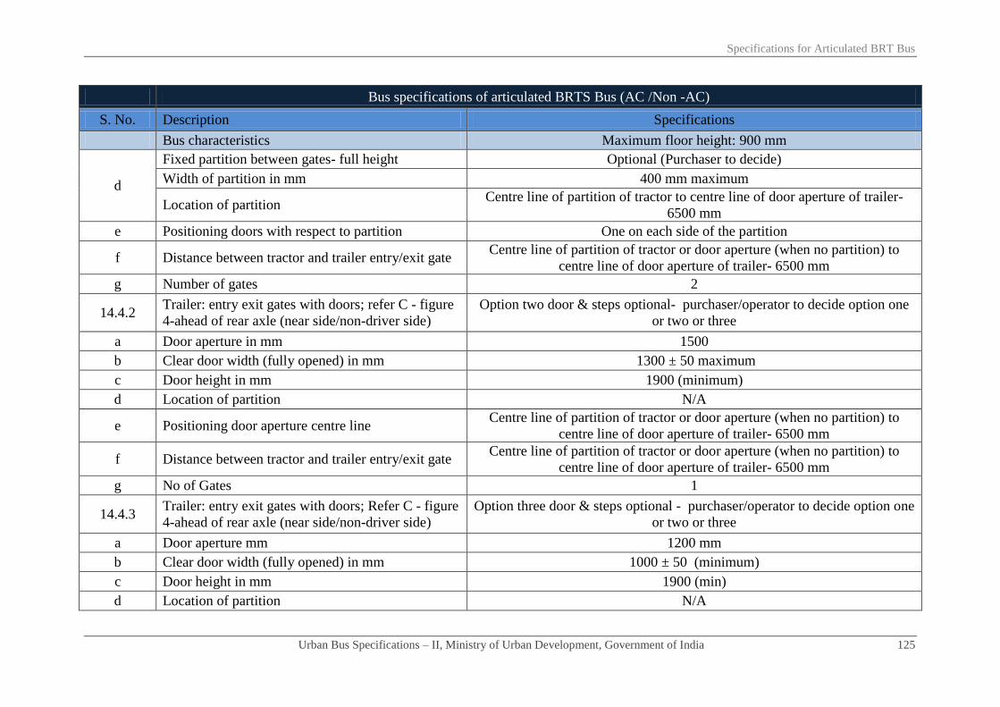
Specifications for Articulated BRT Bus
Urban Bus Specifications – II, Ministry of Urban Development, Government of India 125
Bus specifications of articulated BRTS Bus (AC /Non -AC)
S. No. Description Specifications
Bus characteristics Maximum floor height: 900 mm
d
Fixed partition between gates- full height Optional (Purchaser to decide)
Width of partition in mm 400 mm maximum
Location of partition Centre line of partition of tractor to centre line of door aperture of trailer-
6500 mm
e Positioning doors with respect to partition One on each side of the partition
f Distance between tractor and trailer entry/exit gate Centre line of partition of tractor or door aperture (when no partition) to
centre line of door aperture of trailer- 6500 mm
g Number of gates 2
14.4.2 Trailer: entry exit gates with doors; refer C - figure
4-ahead of rear axle (near side/non-driver side)
Option two door & steps optional- purchaser/operator to decide option one
or two or three
a Door aperture in mm 1500
b Clear door width (fully opened) in mm 1300 ± 50 maximum
c Door height in mm 1900 (minimum)
d Location of partition N/A
e Positioning door aperture centre line Centre line of partition of tractor or door aperture (when no partition) to
centre line of door aperture of trailer- 6500 mm
f Distance between tractor and trailer entry/exit gate Centre line of partition of tractor or door aperture (when no partition) to
centre line of door aperture of trailer- 6500 mm
g No of Gates 1
14.4.3 Trailer: entry exit gates with doors; Refer C - figure
4-ahead of rear axle (near side/non-driver side)
Option three door & steps optional - purchaser/operator to decide option one
or two or three
a Door aperture mm 1200 mm
b Clear door width (fully opened) in mm 1000 ± 50 (minimum)
c Door height in mm 1900 (min)
d Location of partition N/A

Specifications for Articulated BRT Bus
Urban Bus Specifications – II, Ministry of Urban Development, Government of India 126
Bus specifications of articulated BRTS Bus (AC /Non -AC)
S. No. Description Specifications
Bus characteristics Maximum floor height: 900 mm
e Positioning door aperture centre line Centre Line of partition of tractor or door aperture (when no partition) to
centre line of door aperture of trailer- 6500 mm
f Distance between tractor and trailer entry/exit gate Centre Line of partition of tractor or door aperture (when no partition) to
centre line of door aperture of trailer- 6500 mm
g Number of gates 1
14.5 Tractor- entry/exit doors; refer E - figure 4- for (off
side/driver side)- station platform at the same level Required
a Door aperture (without flaps) in mm 1200
b Clear door width (fully opened) in mm 1000 ± 50
c Door height in mm 1900 (minimum)
d
Fixed partition between gates- full height Optional (Purchaser to decide)
Width of partition in mm 400 (maximum)
Location of partition
Vertical centre line of partition max 6500 mm and min 5600 from the front
edge of bus (purchaser/operator to specify preferred distance as per their
BRT facility)
e Positioning doors with respect to partition One on each side of the partition
f Distance between tractor and trailer entry/exit gate Centre line of partition of tractor or door aperture (when no partition) to
centre line of door aperture of trailer- 6500 mm
g Number of gates 2
14.6 Trailer (off side /driver side)
14.6.1
Trailer- entry exit gates with doors; refer D- figure
4 -ahead of rear axle (off side/driver side)- station
platform at same level
Option one (purchaser/operator to decide on option one or two)
a Door aperture (without flaps) in mm 800
b Clear door width (fully opened) in mm 650 ± 50

Specifications for Articulated BRT Bus
Urban Bus Specifications – II, Ministry of Urban Development, Government of India 127
Bus specifications of articulated BRTS Bus (AC /Non -AC)
S. No. Description Specifications
Bus characteristics Maximum floor height: 900 mm
c Door height in mm 1900 (minimum)
d
Fixed partition between gates - full height Optional (Purchaser to decide)
Width of partition in mm 400 (maximum)
Location of partition Centre line of partition of tractor or door aperture (when no partition) to
centre line of door aperture of trailer- 6500 mm
e Positioning doors with respect to partition. One on each side of the partition
f Distance between tractor and trailer entry/exit gate Centre line of partition of tractor or door aperture (when no partition) to
centre line of door aperture of trailer- 6500 mm
g Number of gates 2
14.6.2
Trailer- entry exit gates with doors; refer D- figure
4 -ahead of rear axle (off Side/driver side)- station
platform at same level
Option two (purchaser/operator to decide on option one or two)
a Door aperture in mm 1500
b Clear door width (fully opened) in mm 1300 ± 50 maximum
c Door height in mm 1900 (minimum)
d Location of partition N/A
e Positioning door aperture centre line Centre line of partition of tractor or door aperture (when no partition) to
centre line of door aperture of trailer- 6500 mm
f Distance between tractor and trailer entry/exit gate Centre line of partition of tractor or door aperture (when no partition) to
centre line of door aperture of trailer- 6500 mm
g Number of gates 1
14.7 Applicable for bi-articulated
14.8 Applicable for bi-articulated
14.9 Applicable for bi-articulated
14.9.1 Applicable for bi-articulated

Specifications for Articulated BRT Bus
Urban Bus Specifications – II, Ministry of Urban Development, Government of India 128
Bus specifications of articulated BRTS Bus (AC /Non -AC)
S. No. Description Specifications
Bus characteristics Maximum floor height: 900 mm
14.9.2 Applicable for bi-articulated
14.10 Applicable for bi-articulated
14.11 Applicable for bi-articulated
14.12 Applicable for bi-articulated
14.12.1 Applicable for bi-articulated
14.12.2 Applicable for bi-articulated
14.13 Maximum first step height (mm) from ground-
unladen & un-kneeled position in buses with:
a Stepped type entry (maximum) 400
b Level entry (at station platform height) No steps required
14.14 Maximum height (mm) of other steps; if required 250
14.15 Ramp for wheel chair at the gates Suitable design mechanism for 900 mm floor ht considering that floor level
of bus stops are at 400mm
a Dimensions in mm Minimum width 900
b Material Aluminium alloy with anti-slip coating
c Load carrying capacity > 300 kg
d Device to prevent the wheel chair roll off the sides
when the length exceeds 1200 mm √
e Device to lock wrapped up ramp √
f Kneel ramp control: Kneeling arrangement for kneeling on left side severally and combined.
Kneeling up to 60mm
g Requirement for passenger with limited mobility √
i Wheel chair anchoring- minimum for one wheel
chair √
ii Priority seats Minimum 4 seats

Specifications for Articulated BRT Bus
Urban Bus Specifications – II, Ministry of Urban Development, Government of India 129
Bus specifications of articulated BRTS Bus (AC /Non -AC)
S. No. Description Specifications
Bus characteristics Maximum floor height: 900 mm
iii Stop request √
h Emergency doors/exits or apertures (Numbers) As per AIS 052
Dimensions in mm As per AIS 052
i Door closing requirements for bus movement Bus could move only after door closing completed
i
Power operated service door- construction &
control system of door to be such that a Passenger
is unlikely to be injured/trapped between the doors
while closing
As per AIS 052
iii Door components As per AIS 052
iii Door locks/locking systems/door retention items As per AIS 052
iv Door hinges As per AIS 052
15 Bus body
15.1 Design type approval As per Annexure-3
15.2 Bus structure - materials specifications etc
Material to be decided by the manufacturer OR as per the tender
specifications issues by purchaser. Other requirements as per bus body code.
Material should fulfil strength etc. requirements indicated under Annexure-3
15.3 Insulation
a Roof structure Material to be decided by the manufacturer OR as per the tender
specifications issues by purchaser. Other requirements as per bus body code.
Material should fulfil strength etc. requirements indicated under Annexure-3 b Engine compartment
15.4 Aluminium extruded sections for:
a Rub rail
Aluminium extrusion IS 733/1983 or better b Decorative moulding
c Wire cover

Specifications for Articulated BRT Bus
Urban Bus Specifications – II, Ministry of Urban Development, Government of India 130
Bus specifications of articulated BRTS Bus (AC /Non -AC)
S. No. Description Specifications
Bus characteristics Maximum floor height: 900 mm
d Wearing strip
e Foot step edging
f Panel beading
g Window frame
h Roof grab rail brackets
15.5 Floor type/Materials etc
a Not applicable for BRTS
b Type of floor Uniform flat floor
c Not applicable for BRTS
d Steps on floor No steps/hump inside bus except where required for entry/exit
e Maximum floor slope 6%
f Floor surface material
12mm thickness Phenolic resin bonded densified laminated compressed
wooden floor board (both side plain surface) having density of 1.2 gm/cc
conforming to IS 3513(Part-3): type VI 1989 or latest. The flooring should
also be boiling water resistant as for marine board BIS 710-1976/latest and
fire retardant as per BIS:5509-2000 (IS15061:2002)
g Anti – skid material 3mm thick anti-skid type silicon grains ISO 877/76 for colour, IS5509 for
fire retardancy
15.6 Safety glasses and fittings:
a Front windscreen (laminated) glass:
Single piece laminated safety glass, plain, flat/curved with curved corners
with PVB film IS 2553(Part-2)-1992/latest. Standard designs for each variant
of buses to be followed. (Refer Annexure 1)
Size: 2200mm width*1500mm height (minimum)*8.5±0.5mm thickness
b Rear windscreen: (wherever provided)
Single piece flat/curved toughened glass-plain/flat/curved at centre & curved
at corners IS 2553 (Part-2)–1992/latest
Size: 1900mm width*950mm height (minimum)*5.5±0.5mm thickness
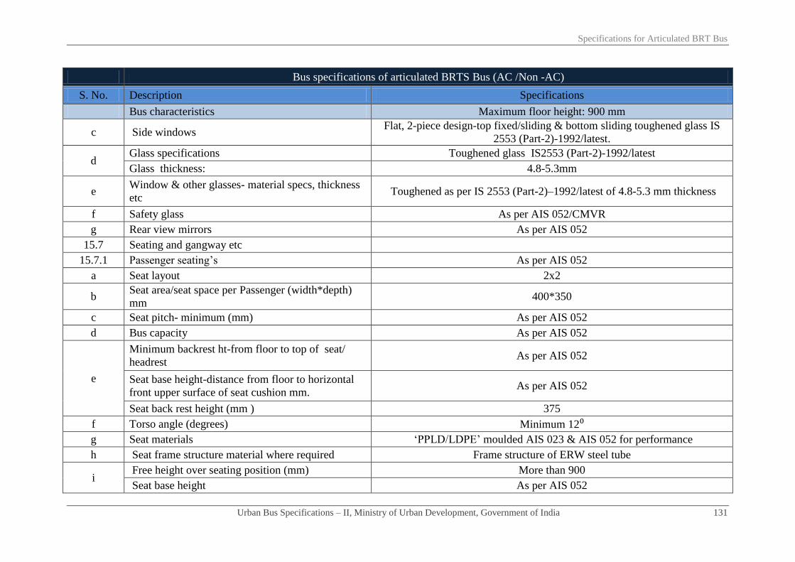
Specifications for Articulated BRT Bus
Urban Bus Specifications – II, Ministry of Urban Development, Government of India 131
Bus specifications of articulated BRTS Bus (AC /Non -AC)
S. No. Description Specifications
Bus characteristics Maximum floor height: 900 mm
c Side windows Flat, 2-piece design-top fixed/sliding & bottom sliding toughened glass IS
2553 (Part-2)-1992/latest.
d Glass specifications Toughened glass IS2553 (Part-2)-1992/latest
Glass thickness: 4.8-5.3mm
e Window & other glasses- material specs, thickness
etc Toughened as per IS 2553 (Part-2)–1992/latest of 4.8-5.3 mm thickness
f Safety glass As per AIS 052/CMVR
g Rear view mirrors As per AIS 052
15.7 Seating and gangway etc
15.7.1 Passenger seating’s As per AIS 052
a Seat layout 2x2
b Seat area/seat space per Passenger (width*depth)
mm 400*350
c Seat pitch- minimum (mm) As per AIS 052
d Bus capacity As per AIS 052
e
Minimum backrest ht-from floor to top of seat/
headrest As per AIS 052
Seat base height-distance from floor to horizontal
front upper surface of seat cushion mm. As per AIS 052
Seat back rest height (mm ) 375
f Torso angle (degrees) Minimum 12⁰
g Seat materials ‘PPLD/LDPE’ moulded AIS 023 & AIS 052 for performance
h Seat frame structure material where required Frame structure of ERW steel tube
i Free height over seating position (mm) More than 900
Seat base height As per AIS 052

Specifications for Articulated BRT Bus
Urban Bus Specifications – II, Ministry of Urban Development, Government of India 132
Bus specifications of articulated BRTS Bus (AC /Non -AC)
S. No. Description Specifications
Bus characteristics Maximum floor height: 900 mm
j Clearance space for seated Passenger facing
partition (mm) Minimum 350
k
Seat back/Pad material/thickness Polyurethane foam IS15061:2002 (padding is optional)
Type MDI Moulded IS 5509
Upholstery Pile Fabric/Jekard 0.7-1mm thickness
l Area for standee passengers (sq. mm.): As per AIS 052
m Number of seats including one for wheel chair Same as bus capacity above
n Number of standees Same as bus capacity above
o Sitting/standing Ratio Not required
p Headrest Not required
q Seats side facing location Not suggested except on wheel arches
r Seat arm Not required
s Magazine pouch Not required
t Individual seat row fans Not required
u Reading lights Not required
v Seat back rest Fixed
w Seat belts & their anchorage Not necessary except diver seat & wheel chair (performance etc. as per AIS
052)
x Performance & strength requirements of: √
i Driver seat AIS 023
ii Passenger seats AIS 023
15.7.2 Gangway:
a Minimum interior head room (centre line of
gangway) in mm 1900 including that in the rear overhang area.

Specifications for Articulated BRT Bus
Urban Bus Specifications – II, Ministry of Urban Development, Government of India 133
Bus specifications of articulated BRTS Bus (AC /Non -AC)
S. No. Description Specifications
Bus characteristics Maximum floor height: 900 mm
i At front axle: As per AIS 052
ii At rear axle: As per AIS 052
iii Other areas As per AIS 052
b Gangway width (mm) from gates to longitudinal
space between seats (access to service doors)
(Ref Figure-1) Minimum 700 mm excluding armrests (armrests are not
required) and including stanchions- will be measured from seat edge to seat
edge.
c Gangway width (mm) in longitudinal space
between seats As above
d
Gangway width (mm) in longitudinal space
between seats (rear of rear edge of the rear door in
RE bus)
As above
e Driver’s working space As per AIS 052
Driver’s seat As per AIS 052
15.8 Corrosion prevention & painting Corrosion prevention treatment/painting for structural members/components,
assembled structure, panels etc,
a
Corrosion prevention treatment
As per clause 3.17 of AIS 052
Internal surfaces of structural members
External surfaces of structural members
After drilling holes/welding
Inter metallic galvanic corrosion prevention
b Primer coating
c Painting:
16 Electrical system
BIS marked, copper conductors with fire retardant as per IS/ISO: 6722:2006
as per appropriate class. Conductor cross-section varying as per circuit
requirements, minimum cross-section 0.5 sq mm. Quality marking may also
be as per equivalent or better European, Japanese, US standards
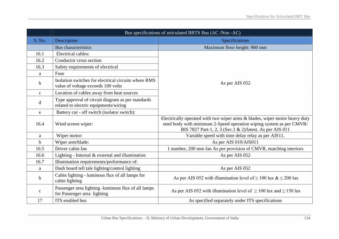
Specifications for Articulated BRT Bus
Urban Bus Specifications – II, Ministry of Urban Development, Government of India 134
Bus specifications of articulated BRTS Bus (AC /Non -AC)
S. No. Description Specifications
Bus characteristics Maximum floor height: 900 mm
16.1 Electrical cables:
As per AIS 052
16.2 Conductor cross section
16.3 Safety requirements of electrical
a Fuse
b Isolation switches for electrical circuits where RMS
value of voltage exceeds 100 volts
c Location of cables away from heat sources
d Type approval of circuit diagram as per standards
related to electric equipments/wiring
e Battery cut - off switch (isolator switch):
16.4 Wind screen wiper:
Electrically operated with two wiper arms & blades, wiper motor heavy duty
steel body with minimum 2-Speed operation wiping system as per CMVR/
BIS 7827 Part-1, 2, 3 (Sec.1 & 2)/latest. As per AIS 011
a Wiper motor: Variable speed with time delay relay as per AIS11.
b Wiper arm/blade: As per AIS 019/AIS011
16.5 Driver cabin fan 1 number, 200 mm fan As per provision of CMVR, matching interiors
16.6 Lighting - Internal & external and illumination As per AIS 052
16.7 Illumination requirements/performance of:
a Dash board tell tale lighting/control lighting As per AIS 052
b Cabin lighting - luminous flux of all lamps for
cabin lighting As per AIS 052 with illumination level of ≥ 100 lux & ≤ 200 lux
c Passenger area lighting -luminous flux of all lamps
for Passenger area lighting As per AIS 052 with illumination level of ≥ 100 lux and ≤ 150 lux
17 ITS enabled bus As specified separately under ITS specifications

Specifications for Articulated BRT Bus
Urban Bus Specifications – II, Ministry of Urban Development, Government of India 135
Bus specifications of articulated BRTS Bus (AC /Non -AC)
S. No. Description Specifications
Bus characteristics Maximum floor height: 900 mm
18 Safety related items:
18.1 Driver seat belt & anchorage duly type approved. ELR recoil type, 3 point mounting as per CMVR & AIS 052 conforming to
AIS 005 & 015
18.2 Passengers seat belt:
Not necessary except diver seat & wheel chair (performance etc. as per AIS
052) Number:
18.3 Driver/Passenger/wheelchair seat belt anchorage
18.4 Fire extinguisher: As per AIS 052
18.5 First aid box: 1 number, As per provision of CMVR
18.6 Handrails minimum length*diameter*height above
floor: mm
Colour contrasting and slip resistant of aluminium tubing 32 mm dia, 3 mm
thick. Rest as per AIS 052
18.7 Handholds: Colour contrasting and slip resistant. 2 to 4 Nos. hand holds per bay. Rest as
per AIS 052
18.8 Stanchions:
Vertically fitted, aluminium tubing with Colour contrasting and slip
resistant. 40 mm diameter & 3.15 mm thick. Rest as per AIS 052. As an
alternative to stanchions mounted on bus floor, stanchions mounted on top of
seat frames (new version seats) be explored (ref figure-2).
18.9 Not applicable for BRTS
18.10 Passenger stop request signal
High visibility bell pushes/pully chord/touch tape shall be fitted at a height
of 1.2 meter on all alternate stanchions mainly for persons with disabilities.
(optional)
18.11 Window guardrails:
a In all school buses - minimum numbers. Not Applicable
b In all other buses - minimum numbers. As per AIS 052
c In AC super deluxe buses As per AIS 052
d Other details:

Specifications for Articulated BRT Bus
Urban Bus Specifications – II, Ministry of Urban Development, Government of India 136
Bus specifications of articulated BRTS Bus (AC /Non -AC)
S. No. Description Specifications
Bus characteristics Maximum floor height: 900 mm
i First guard rail at a height from window sill mm
ii The distance between two guard rails mm
18.12 Entrance/Exit Guard/Step well guard: 800 mm minimum height extending ≥ 100 mm more than centre line of
sitting position of the Passenger.
18.13 Emergency exit doors, warning devices etc: As per AIS 052/CMVR
18.14 Front/rear door, step well lights, door open sign Incandescent bulb/LED as per AIS 008
18.15 Mirrors right/left side exterior/interior: Convex as per AIS 001 & 002. Interior with double curvature
18.16 Towing device front/rear Heavy duty 1.2 times (minimum) the kerb weight of the bus with 30
o of the
longitudinal axis of the bus. As per CMVR & IS 9760- Ring Type
18.17 Warning triangle As per AIS 052/CMVR
18.18 Fog lighting As per AIS 052/CMVR
18.19 Bumpers- front and rear
Both made of Steel or impact resistant polymer or combination of both
meeting requirement of an energy absorbing system
Impact strength for bumpers Meet requirement of Para 6.3.1 of AIS 052
19 Miscellaneous items/requirements
19.1 Windows
a Type of window Sliding type window panes except ACX bus
b Minimum height of window aperture (clear vision)1 ≥ 950 mm in type I -NDX & SDX
c Min height of upper edge of window aperture from
bus floor As per AIS 052
d Minimum width of windows (clear vision zone) As per AIS 052
19.2 Cabin luggage carrier Not required
19.3 Life cycle requirements of bus 12 years or 10,00,000 km
1 Clear vision includes partition between fixed and sliding glass subject to a maximum width of 100 mm

Specifications for Articulated BRT Bus
Urban Bus Specifications – II, Ministry of Urban Development, Government of India 137
Bus specifications of articulated BRTS Bus (AC /Non -AC)
S. No. Description Specifications
Bus characteristics Maximum floor height: 900 mm
20 Air conditioning system- test procedure for type
approval
20.1 Specifications a) For up to 42°C of saloon temperature and b) For > 42°C of saloon
temperature
20.2 Target results
a) 24± 4°C (up to 42°C)
b) Temperature gradient of 15° ( > 42°C of saloon temperature) eg. If the
saloon temperature is 45o, then the target temperature inside the bus is 45
o-
15o= 30
o
c) Minimum average air velocity at air vent is 4.5 m/s
20.3 Apparatus Lab condition and heating chamber
20.4 Procedure
1. Soak for 1 hour
2. At 2000 rpm
3.Upto 42°C: pull down time 30 minutes (maximum) (for more than 42°C
of saloon temperature, pull down time within 40 minutes (maximum))
4. Thermocouple to be placed over place minimum 20 numbers. at nose level
20.5
Air curtains on entry/exit gates to avoid loss/gain of
heat and or cool air when doors are frequently
opened for boarding/alighting of Passenger with
min air flow of 1000±50 m³/hr at each gate. Type of
air curtains at entry exit gates their power
consumption etc be accounted for while deciding
engine power, etc
Required
21 Additional requirements
21.1 Air circulations and ventilation in driver's area
An air passage/duct/roof hatch to be provided in driver area at a suitable
location for proper inflow of air inside the driver cab
Drivers work area to be provided with blower or
suitable device (200 mm diameter fan) to ensure

Specifications for Articulated BRT Bus
Urban Bus Specifications – II, Ministry of Urban Development, Government of India 138
Bus specifications of articulated BRTS Bus (AC /Non -AC)
S. No. Description Specifications
Bus characteristics Maximum floor height: 900 mm
proper ventilation. These devices may be capable of 3
– speed adjustment
21.2
Maximum noise levels inside the saloon
(irrespective of AC, non-AC/fuel type/engine
location)- test procedure as per AIS020
84 dba (to be achieved a max noise level of 81 dba from 1st April 2015
onwards)
22 Fuel efficiency requirement While tendering, purchaser/operator may take into account the higher
weightage for more fuel efficient vehicle under standard test conditions

Chapter - 09
Specifications for Bi-articulated BRT
bus for guidance

Specifications for Bi-Articulated BRT Bus for Guidance
Urban Bus Specifications – II, Ministry of Urban Development, Government of India 139
Bus specifications for Bi-articulated BRTS Bus (AC/Non -AC) for Guidance
S. No. Description Specifications
Bus characteristics Maximum floor height:900 mm
Bus floor height Floor height shall be uniform inside the vehicle
1 Propulsion system ICE. electrical, hybrid, fuel cell
2 Fuel-options Fuel to be compatible with propulsion system & prescribed
emission norms
3 Engine
3.1 Engine HP sufficient to provide:
a Rated performance at GVW in a stop/start urban operations Geared maximum speed without speed limiter to be 75 kmph
b Acceleration (meter/sec²) ≥ 0.8
c Attain bus speed of 0-30 kmph in seconds ≤ 10.5
d Maximum speed Geared maximum speed without speed limiter to be 75 kmph
e Grade ability from stop at GVW 17%
f Rated HP/torque preferably at lower rpm range Maximum engine torque required at lower range of RPM and
spread over a wider range of RPM
3.2 Emission norms BS III/BS IV or latest as applicable
3.3 Engine management Engine oil pressure, engine coolant temperature, engine speed in
RPM, vehicle speed, diagnostic details message (engine specific)
3.4 Engine operational requirements
Engine should be able to operate efficiently at ambient
temperatures of approximately 0⁰C to 50⁰C, humidity level from
5% to 100%, and altitude levels of up to 2000 meters, generally
operating in the semi arid zone/hilly region prevailing in the area
3.5 Engine location Front in tractor/rear of the second trailer module of bi-articulated
bus
3.6 Transmission
Purchasers to select any one transmission system. a Automatic with torque convertor. Neutral during stops
b Automated manual

Specifications for Bi-Articulated BRT Bus for Guidance
Urban Bus Specifications – II, Ministry of Urban Development, Government of India 140
Bus specifications for Bi-articulated BRTS Bus (AC/Non -AC) for Guidance
S. No. Description Specifications
Bus characteristics Maximum floor height:900 mm
4 Operational safety
Transmission system to be fitted with a mechanism which makes
it possible to engage reverse gear only when vehicle is stationary
(applicable for automatic & automatic manual transmission)
5 Clutch (where applicable) Dry, single plate, power assisted operation
5.1 Applicable for articulated
5.2 Applicable for articulated
5.3 Applicable for articulated
5.4.1 Rear axles of front engine Bi-articulated bus in:
a Rear axle of tractor – the drive axle Single reduction, hypoid gears, full floating axle shafts with
optimal gear ratios suitable for urban operations
b Trailer 1 (non drive axle) Heavy duty rigid axle
c Trailer 2 (non drive axle) Heavy duty rigid axle
5.4.2 Rear axles of rear engine Bi-articulated bus in:
a Trailer 1 - non drive axle Heavy duty rigid axle
b Trailer 2 - the drive axle - rear axle Single reduction, hypoid gears, full floating axle shafts with
optimal gear ratios suitable for urban operations
c Tractor - non drive rear axle Heavy duty rigid axle
6 Steering system Hydraulic power steering with height and angle adjustment
7 Suspension system Fully Pneumatic complete with ECAS/Electronic management
and control systems
7.1 Front Air bellows-2 numbers.
7.2 Applicable for articulated
7.3 Rear axle of tractor Air bellows-4 numbers
7.4 Trailer 1 Air bellows-4 numbers
7.5 Trailer 2 Air bellows-4 numbers

Specifications for Bi-Articulated BRT Bus for Guidance
Urban Bus Specifications – II, Ministry of Urban Development, Government of India 141
Bus specifications for Bi-articulated BRTS Bus (AC/Non -AC) for Guidance
S. No. Description Specifications
Bus characteristics Maximum floor height:900 mm
7.6 Kneeling (mm) Minimum 60 mm entry/exit side severally & collectively in
mixed traffic on direct routes
7.7 Anti roll bars/stabilizers1 Rear axle of tractor, trailer 1 and trailer 2; and Front axle
7.8 Shock absorbers Hydraulic double acting at all axles
7.9 Electronic controls of suspension system for: Electronically controlled air suspension or superior system
a
Controlling floor level √ √
Levelling control for manoeuvring ≤ 80mm ≤ 80mm
b Enhancing comfort by absorbing shocks in case of road
irregularities √ √
c Uniform spring rate in all loading conditions √ √
d Self correction of bellow height to:
√ √
i Help protect driveline angularity related problems
ii Counter road unevenness
iii Monitor bellow failures
iv Provide passenger comfort
8 Braking System
Dual circuit full air brakes, with preferably disc type
arrangement for front and drum at rear brakes. Graduated hand
controlled, spring actuated parking brakes acting on rear wheels
(any bus delivered after 1st April, 2015 will mandatorily have
disc brake in front)
8.1 Anti skid anti brake locking system (ABS) As per CMVR
8.2 Electronic controls Required
1 Optional in case of independent suspension

Specifications for Bi-Articulated BRT Bus for Guidance
Urban Bus Specifications – II, Ministry of Urban Development, Government of India 142
Bus specifications for Bi-articulated BRTS Bus (AC/Non -AC) for Guidance
S. No. Description Specifications
Bus characteristics Maximum floor height:900 mm
8.3 Electronic monitoring of brakes: continuous monitoring of √ √
a Brake pad condition √ √
b Brake pad temperature condition √ √
c Door- brake inter locking √ √
9 Electrical system 24 volt DC
9.1 Batteries
Low maintenance type lead acid batteries for 24 V system-
performances as per BIS 14257-1995 (latest). 2*12V of
commensurate capacity. Maintenance free batteries preferred.
9.2 Self starter 24V
9.3 Alternator 24V (another alternator of similar capacity for AC buses)
9.4 Electrical wiring & controls- type As specified separately under ITS specifications
10 Speed limiting device (optional) Electronic type duly approved/certified as per AIS – 018/2001 or
latest, tamper proof and be adjusted to applicable speed limit
11 Tyres Steel radial tube-less. Size and performance as per CMVR
12 Fuel tank
Capable to enable bus operation ≥ 300 km between consecutive
fillings
Fuel tank location Optional
13 Bus characteristics
13.1 Bus dimensions mm
a Overall length (over body excluding bumper) 25000 (-500 mm tolerance)
b Overall width (sole bar/floor level- extreme points) 2600 (maximum)
c Overall height (unladen)-(At extreme point) 3800 (maximum)
d Wheel-base

Specifications for Bi-Articulated BRT Bus for Guidance
Urban Bus Specifications – II, Ministry of Urban Development, Government of India 143
Bus specifications for Bi-articulated BRTS Bus (AC/Non -AC) for Guidance
S. No. Description Specifications
Bus characteristics Maximum floor height:900 mm
i Tractor - between centre line of front axle to centre line of its rear
axle 5900 (-100 mm tolerance)
ii Trailer 1: centre line of rear axle of tractor to centre line of axle of
trailer 1 5900 (-100 mm tolerance)
iii Trailer 2: centre line of axle of trailer 1 to centre line of axle of
trailer 2 7600 (-100+200 mm as tolerance)
e Front overhang As per CMVR
f Rear overhang of trailer 2 As per CMVR
13.2 Maximum turning circle radius (mm) As per CMVR
13.3 Floor height above ground (mm) Maximum 900 with tolerance ± 20
13.4 Clearances (mm)
a Axle clearance (mm) Minimum 190 mm
b Wheel area clearance (mm) > 220 mm for parts fixed to bus body & > 170 mm for the parts
moving vertically with axle
c Minimum ground clearance (un-kneeled) at GVW Within the wheelbase not less than 240mm
13.5 Angles (degrees)
a Angle of approach (unladen) Not less than 8.5⁰
b Angle of departure (unladen) Not less than 9.0⁰
c Ramp over angle (half of break-over angle) Not less than 4.8⁰
13.6 Bus articulation system– for puller/pusher type bi-articulated bus
a Bus articulation system - general requirements
Heavy-duty articulation system
Suitable for vehicles with higher axle loads
Simple and clearly defined connection surfaces

Specifications for Bi-Articulated BRT Bus for Guidance
Urban Bus Specifications – II, Ministry of Urban Development, Government of India 144
Bus specifications for Bi-articulated BRTS Bus (AC/Non -AC) for Guidance
S. No. Description Specifications
Bus characteristics Maximum floor height:900 mm
Problem-free fitting to front and rear vehicle segments
Nearly maintenance free
Robust with low sensitivity to dirt and soiling
Easy accessibility to sub systems for maintenance/replacement
Fitted with an electronic control system that detects the driving
situation
Suitable Mechanism for anti-jack- knife joint required
Controls driving performance and also conducts a system
diagnosis for early detection of any defects.
Interconnecting unit design to prevent separation of tractor &
trailer units even in an accident with another vehicle required
Fitting with an electronic control system that detect the driving
situation, identify faults and warns for a corrective action
b Turn table
Robust design, suitable for puller/pusher type articulated bus;
Suitable mechanism to minimize honing of floor edges/prevent
tripping hazard
c Horizontal articulation along longitudinal axis ± 50⁰ with 2⁰ tolerance
d Vertical articulation along transverse axis ± 10⁰ with 1⁰ tolerance
e Dampers
An integrated sensor mechanism enabling continuous monitoring
of the defined damper values.
The system to ensure a minimum damping, even on failure of the
electronic components.
2- stage damping system may be considered as an optional
system
f Bellows
The bellows completely enclosing the gangway is closed under
the articulation.
Material for the folding bellows- synthetic rubber coated

Specifications for Bi-Articulated BRT Bus for Guidance
Urban Bus Specifications – II, Ministry of Urban Development, Government of India 145
Bus specifications for Bi-articulated BRTS Bus (AC/Non -AC) for Guidance
S. No. Description Specifications
Bus characteristics Maximum floor height:900 mm
polyester material made up of three layers of synthetic rubber and
two layers of polyester mats. The material sewn together and the
outside seams crimped with an aluminium reinforcement profile
to give the bellows structural stiffness.
An aluminium J shaped extrusion bent to follow the contour of
the bus body with a gap under the articulated joint may be riveted
to the bus body end. The folding bellow collar may be fixed into
this J section with a seal and the bellows be held to the bus body
by tensioning the cable.
A typical bus bellows installation would have two bellows that
are connected to a centre hoop located in the centre of the
articulation. This centre hoop manufactured from an aluminium
extrusion forms to provide seating for the collar of the bellows
and its seal. This hoop may be steered by a pantograph steering
system that position the centre hoop so that it halves both the
horizontal articulation angle (52°maximum) and the vertical
articulation angle(11° maximum.)
14 Bus Gates/ Doors
14.1 Type of doors Double jack knife on near side (non- driver side) and on off side
(driver side)
a Operating mechanism Electro pneumatically controlled
b Opening closing time in seconds per operation (maximum) 4
c Positions of door controls On dashboard, as also inside & outside of doors
d Passenger safety system- allowing bus motion on doors closing Mandatory

Specifications for Bi-Articulated BRT Bus for Guidance
Urban Bus Specifications – II, Ministry of Urban Development, Government of India 146
Bus specifications for Bi-articulated BRTS Bus (AC/Non -AC) for Guidance
S. No. Description Specifications
Bus characteristics Maximum floor height:900 mm
14.2 Front service doors; refer A - figure 5- (near side/non-driver side)-
no station platform; steps required at door Required
a Door aperture (without flaps) in mm 800 (minimum)
b Clear door width (fully opened) in mm 650 ± 50
c Door height in mm 1900 (minimum)
d Positioning front service gate Ahead of front axle
e Number of gates 1
14.3 Applicable for articulated
14.4 Applicable for articulated
14.4.1 Applicable for articulated
14.4.2 Applicable for articulated
14.4.3 Applicable for articulated
14.5 Applicable for articulated
14.6 Applicable for articulated
14.6.1 Applicable for articulated
14.6.2 Applicable for articulated
14.7 Tractor entry/exit gate; refer B- figure 5 -(near side doors/non-
driver side) location Door & steps optional- purchaser/operator to decide
a Door aperture (without flaps) in mm 1200 mm
b Clear door width (fully opened) in mm 1000 ± 50
c Door height in mm 1900 (minimum)
d Fixed partition between gates - full height Optional (Purchaser to decide)
e Width of partition in mm 400 (maximum)

Specifications for Bi-Articulated BRT Bus for Guidance
Urban Bus Specifications – II, Ministry of Urban Development, Government of India 147
Bus specifications for Bi-articulated BRTS Bus (AC/Non -AC) for Guidance
S. No. Description Specifications
Bus characteristics Maximum floor height:900 mm
f Location of partition
Vertical centre line of partition max 6500 mm and min 5600 from
the front edge of bus (purchaser/operator to specify preferred
distance as per their BRT facility)
g Positioning doors with respect to partition One on each side of the partition
h Distance between tractor and trailer 1 entry/exit gate Centre line of partition of tractor or door aperture (when no
partition) to centre line of door aperture of trailer 1- 6500 mm
i Number of gates 2
14.8 Trailer 1 entry exit gate with doors; refer C- figure 5 -ahead of
trailer 1 rear axle (near side/non-driver side): Door & steps optional - purchaser/operator to decide
a Door aperture (without flaps) in mm 1200
b Clear door width (fully opened) in mm 1000 ± 50
c Door height in mm 1900 (minimum)
d Number of gates 1
e Distance between trailer 1 and trailer 2 entry/exit gate Centre line of door aperture of trailer 1 to centre line of partition
or door aperture (when no partition) of trailer 2- 6500 mm
14.9 Trailer 2 (near side/non driver side)
14.9.1 Trailer 2 entry exit gate with doors ; refer D- figure 5 ahead of
trailer 2 rear axle (near side/non-driver side)
Option one door & steps optional - purchaser/operator to decide
option one or two
a Door aperture (without flaps) in mm 800
b Clear door width (fully opened) in mm 650 ± 50
c Door height in mm 1900 (minimum)
d Fixed Partition between gates- full height Optional (Purchaser to decide)
e Width of partition in mm 400 (maximum)
f Location of partition Centre line of door aperture of trailer 1 to centre line of partition

Specifications for Bi-Articulated BRT Bus for Guidance
Urban Bus Specifications – II, Ministry of Urban Development, Government of India 148
Bus specifications for Bi-articulated BRTS Bus (AC/Non -AC) for Guidance
S. No. Description Specifications
Bus characteristics Maximum floor height:900 mm
or door aperture (when no partition) of trailer 2- 6500 mm
g Positioning doors with respect to partition. One on each side of the partition
h Distance between trailer 1 and trailer 2 entry/exit gate Centre line of door aperture of trailer 1 to centre line of partition
or door aperture (when no partition) of trailer 2- 6500 mm
i Number of gates 2
14.9.2 Trailer 2 entry exit gate with doors; refer D- figure 5 ahead of
trailer 2 rear axle (near side/non-driver side)
Option two door & steps optional- purchaser/operator to decide
option one or two
a Door aperture in mm 1500
b Clear door width (fully opened) in mm 1300 ± 50 (maximum)
c Door height in mm 1900 (minimum)
d Location of partition N/A
e Positioning door aperture centre line Centre Line of door aperture of trailer 1 to Centre Line of door
aperture of trailer 2- 6500 mm
f Distance between tractor and trailer entry/exit gate Centre Line of door aperture of trailer 1 to Centre Line of door
aperture of trailer 2- 6500 mm
g Number of gates 1
14.10 Tractor- front near side doors; refer G -figure 5 - (off side/driver
side) location Required
a Door aperture (without flaps) in mm 1200
b Clear door width (fully opened) in mm 1000 ± 50
c Door height in mm 1900 (minimum)
d Fixed partition between gates- full height Optional (Purchaser to decide)
e Width of partition in mm 400 (maximum)
f Location of partition Vertical centre line of partition max 6500 mm and min 5600 from
the front edge of bus (purchaser/operator to specify preferred

Specifications for Bi-Articulated BRT Bus for Guidance
Urban Bus Specifications – II, Ministry of Urban Development, Government of India 149
Bus specifications for Bi-articulated BRTS Bus (AC/Non -AC) for Guidance
S. No. Description Specifications
Bus characteristics Maximum floor height:900 mm
distance as per their BRT facility)
g Positioning doors with respect to partition One on each side of the partition
h Distance between tractor and trailer 1 entry/exit gate Centre line of partition of tractor or door aperture (when no
partition) to centre line of door aperture of trailer 1- 6500 mm
i Number of gates 2
14.11
Trailer 1- entry exit gate with doors; refer F- figure 5- ahead of
trailer 1 rear axle; (off Side/driver side)- station platform at same
level
Required
a Door aperture (without flaps) in mm 1200
b Clear door width (fully opened) in mm 1000 ± 50
c Door height in mm 1900 (minimum)
d Number of gates 1
e Distance between trailer 1 and trailer 2 entry/exit gate Centre line of partition of tractor or door aperture (when no
partition) to centre line of door aperture of trailer 1- 6500 mm
14.12 Trailer 2 (off side/driver side)
14.12.
1
Trailer 2 entry/exit gate with doors; refer E- figure 5 ahead of
trailer 2 rear axle (off side/driver side) Option one door & steps optional - purchaser/operator to decide
a Door aperture (without flaps) in mm 800
b Clear door width (fully opened) in mm 650 ± 50
c Door height in mm 1900 mm (minimum)
d Fixed Partition between gates- full height Optional (Purchaser to decide)
e Width of partition in mm 400 (maximum)
f Location of partition Centre line of door aperture of trailer 1 to centre line of partition
or door aperture (when no partition) of trailer 2- 6500 mm
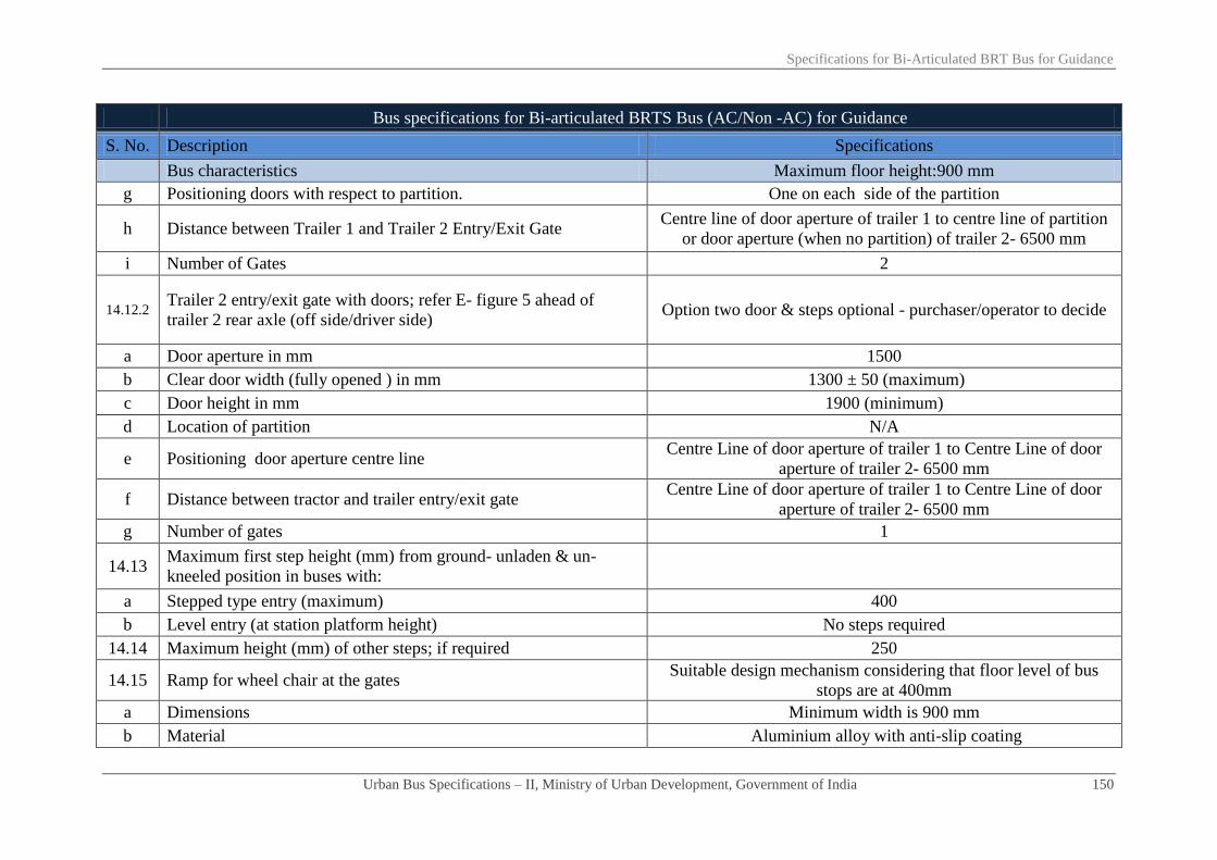
Specifications for Bi-Articulated BRT Bus for Guidance
Urban Bus Specifications – II, Ministry of Urban Development, Government of India 150
Bus specifications for Bi-articulated BRTS Bus (AC/Non -AC) for Guidance
S. No. Description Specifications
Bus characteristics Maximum floor height:900 mm
g Positioning doors with respect to partition. One on each side of the partition
h Distance between Trailer 1 and Trailer 2 Entry/Exit Gate Centre line of door aperture of trailer 1 to centre line of partition
or door aperture (when no partition) of trailer 2- 6500 mm
i Number of Gates 2
14.12.2 Trailer 2 entry/exit gate with doors; refer E- figure 5 ahead of
trailer 2 rear axle (off side/driver side) Option two door & steps optional - purchaser/operator to decide
a Door aperture in mm 1500
b Clear door width (fully opened ) in mm 1300 ± 50 (maximum)
c Door height in mm 1900 (minimum)
d Location of partition N/A
e Positioning door aperture centre line Centre Line of door aperture of trailer 1 to Centre Line of door
aperture of trailer 2- 6500 mm
f Distance between tractor and trailer entry/exit gate Centre Line of door aperture of trailer 1 to Centre Line of door
aperture of trailer 2- 6500 mm
g Number of gates 1
14.13 Maximum first step height (mm) from ground- unladen & un-
kneeled position in buses with:
a Stepped type entry (maximum) 400
b Level entry (at station platform height) No steps required
14.14 Maximum height (mm) of other steps; if required 250
14.15 Ramp for wheel chair at the gates Suitable design mechanism considering that floor level of bus
stops are at 400mm
a Dimensions Minimum width is 900 mm
b Material Aluminium alloy with anti-slip coating

Specifications for Bi-Articulated BRT Bus for Guidance
Urban Bus Specifications – II, Ministry of Urban Development, Government of India 151
Bus specifications for Bi-articulated BRTS Bus (AC/Non -AC) for Guidance
S. No. Description Specifications
Bus characteristics Maximum floor height:900 mm
c Load carrying capacity > 300 kg
d Device to prevent the wheel chair roll off the sides when the length
exceeds 1200 mm √
e Device to lock wrapped up ramp √
f Kneel ramp control Kneeling arrangement for Kneeling on left side severally and
combined. Kneeling up to 60mm
g Requirement for passenger with limited mobility √
i Wheel chair anchoring- minimum for one wheel chair √
ii Priority seats Minimum 4 seats
iii Stop request √
h Emergency doors/exits or apertures (Numbers) As per AIS 052
Dimensions (mm) As per AIS 052
i Passenger safety system - allowing bus motion on doors closing
and doors opening only when the bus is stopped Mandatory
i
Power operated service door- construction & control system of
door to be such that a Passenger is unlikely to be injured/trapped
between the doors while closing
As per AIS 052
ii Door components As per AIS 052
iii Door locks/locking systems/door retention items As per AIS 052
iv Door hinges As per AIS 052
15 Bus body
15.1 Design type approval As per Annexure-3
15.2 Bus structure- materials specifications etc Material to be decided by the manufacturer OR as per the tender

Specifications for Bi-Articulated BRT Bus for Guidance
Urban Bus Specifications – II, Ministry of Urban Development, Government of India 152
Bus specifications for Bi-articulated BRTS Bus (AC/Non -AC) for Guidance
S. No. Description Specifications
Bus characteristics Maximum floor height:900 mm
specifications issues by purchaser. Other requirements as per bus
body code. Material should fulfil strength etc. requirements
indicated under Annexure-3
15.3 Insulation
a Roof structure Material to be decided by the manufacturer OR as per the tender
specifications issues by purchaser. Other requirements as per bus
body code. Material should fulfil strength etc. requirements
indicated under Annexure-3 b Engine compartment
15.4 Aluminium extruded sections for:
a Rub rail
Aluminium extrusion IS 733/1983 or better
b Decorative moulding
c Wire cover
d Wearing Strip
e Foot step edging
f Panel beading
g Window frame
h Roof grab rail brackets
15.5 Floor type/Materials etc
a Type of floor N/A
b Type of floor Uniform flat floor
c Steps on floor N/A
d Steps on floor No steps/hump inside bus except where required for entry/exit
e Maximum floor slope 6% (As per AIS 052)
f Floor surface material 12 mm thickness phenolic resin bonded densified laminated
compressed wooden floor board (both side plain surface) having

Specifications for Bi-Articulated BRT Bus for Guidance
Urban Bus Specifications – II, Ministry of Urban Development, Government of India 153
Bus specifications for Bi-articulated BRTS Bus (AC/Non -AC) for Guidance
S. No. Description Specifications
Bus characteristics Maximum floor height:900 mm
density of 1.2 gm/cc conforming to IS 3513(part-3): type VI 1989
or latest. The flooring should also be boiling water resistant as for
marine board BIS 710-1976/latest and fire retardant as per BIS
5509-2000 (IS 15061:2002)
g Anti– skid material 3 mm thick anti-skid type silicon grains ISO 877/76 for colour,
IS5509 for fire retardancy
15.6 Safety glasses and fittings:
a
Front windscreen (laminated) glass
Single piece laminated safety glass, plain, flat, curved with
curved corners with PVB film IS 2553 (Part-2)-1992/latest.
Standard designs for each variant of buses to be followed. (Refer
Annexure 1)
Size 2200mm width*1500mm height (minimum)*8.5±0.5mm
thickness
b Rear windscreen: (wherever provided)
Single piece flat/curved toughened glass-plain/flat/curved at
centre & curved at corners IS 2553 (part-2)–1992/latest
Size 1900mm width*950mm height (minimum)*5.5±0.5mm thickness
c Side windows Flat, 2-piece design-top fixed/sliding & bottom sliding toughened
glass IS 2553 (Part-2)-1992/latest
d Glass specifications Toughened glass IS 2553 (Part-2)-1992/ latest
Glass thickness 4.8-5.3 mm
e Window & other glasses- material specifications, thickness etc Toughened as per IS 2553 (Part-2)–1992/latest of 4.8-5.3 mm
thickness
f Safety glass As per AIS 052/CMVR
g Rear view mirrors As per AIS 052
15.7 Seating and gangway etc
15.7.1 Passenger seating’s As per AIS 052

Specifications for Bi-Articulated BRT Bus for Guidance
Urban Bus Specifications – II, Ministry of Urban Development, Government of India 154
Bus specifications for Bi-articulated BRTS Bus (AC/Non -AC) for Guidance
S. No. Description Specifications
Bus characteristics Maximum floor height:900 mm
a Seat layout 2x2
b Seat area/seat space per Passenger (width*depth) mm 400*350
c Seat pitch- minimum in mm As per AIS 052
d Bus capacity As per AIS 052
e
Minimum back rest height-from floor to top of seat/headrest As per AIS 052
Seat base height-distance from floor to horizontal front upper
surface of seat cushion mm. As per AIS 052
Seat back rest height in mm 375
f Torso angle Minimum 12⁰
g Seat materials ‘PPLD/LDPE’ moulded AIS 023 & AIS 052 for performance
h Seat frame structure material where required Frame structure of ERW steel tube
i Free height over seating position in mm More than 900
Seat base height As per AIS 052
j Clearance space for seated Passenger facing partition mm Minimum 350
k
Seat back/Pad material/thickness Polyurethane foam IS 15061:2002 (padding is optional)
Type MDI moulded IS 5509
Upholstery Pile fabric/Jekard 0.7-1 mm thickness
l Area for standee passengers (sq. mm) As per AIS 052
m Number of seats including one for wheel chair Same as bus capacity above
n Number of standees Same as bus capacity above
o Sitting/Standing ratio Not required
p Headrest Not required
q Seats side facing location Not suggested except on wheel arches

Specifications for Bi-Articulated BRT Bus for Guidance
Urban Bus Specifications – II, Ministry of Urban Development, Government of India 155
Bus specifications for Bi-articulated BRTS Bus (AC/Non -AC) for Guidance
S. No. Description Specifications
Bus characteristics Maximum floor height:900 mm
r Seat arm Not required
s Magazine pouch Not required
t Individual seat row fans Not required
u Reading lights Not required
v Seat back rest Fixed
w Seat belts & their anchorage Not necessary except diver seat & wheel chair (performance etc.
as per AIS 052)
x Performance & strength requirements of: √
i Driver seat AIS 023
ii Passenger seats AIS 023
15.7.2 Gangway:
a Minimum interior head room (centre line of gangway) in mm 1900 including that in the rear over hang area
i At front axle As per AIS 052
ii At rear axle As per AIS 052
iii Other areas As per AIS 052
b Gangway width (mm) from gates to longitudinal space between
seats (access to service doors)
(Refer figure-1) minimum 700 mm excluding armrests (armrests
are not required) and including stanchions- will be measured
from seat edge to seat edge.
c Gangway width (mm) in longitudinal space between seats As above
d Gangway width (mm) in longitudinal space between seats (rear of
rear edge of the rear door in rear engine bus) As above
e Driver’s working space As per AIS 052

Specifications for Bi-Articulated BRT Bus for Guidance
Urban Bus Specifications – II, Ministry of Urban Development, Government of India 156
Bus specifications for Bi-articulated BRTS Bus (AC/Non -AC) for Guidance
S. No. Description Specifications
Bus characteristics Maximum floor height:900 mm
Driver’s seat As per AIS 052
15.8 Corrosion prevention & painting Corrosion prevention treatment/painting for structural
members/components, assembled structure, panels etc,
a
Corrosion prevention treatment
As per clause 3.17 of AIS 052
Internal surfaces of structural members
External surfaces of structural members
After drilling holes/welding
Inter metallic galvanic corrosion prevention
b Primer coating
c Painting
16 Electrical system
BIS marked, copper conductors with fire retardant as per IS/ISO
6722:2006 as per appropriate class. Conductor cross-section
varying as per circuit requirements, minimum cross-section 0.5
sq mm. Quality marking may also be as per equivalent or better
European, Japanese, US standards
16.1 Electrical cables
As per AIS 052
16.2 Conductor cross section
16.3 Safety requirements of electrical
a Fuse
b Isolation switches for electrical circuits where RMS value of
voltage exceeds 100 volts
c Location of cables away from heat sources
d Type approval of circuit diagram as per standards related to electric
equipments/wiring
e Battery cut- off switch (isolator switch)

Specifications for Bi-Articulated BRT Bus for Guidance
Urban Bus Specifications – II, Ministry of Urban Development, Government of India 157
Bus specifications for Bi-articulated BRTS Bus (AC/Non -AC) for Guidance
S. No. Description Specifications
Bus characteristics Maximum floor height:900 mm
16.4 Wind screen wiper
Electrically operated with two wiper arms & blades, wiper motor
heavy duty steel body with minimum 2-Speed operation Wiping
system as per CMVR/BIS 7827 Part-1, 2, 3 (Sec.1 & 2)/latest. As
per AIS 011
a Wiper motor Variable speed with time delay relay as per AIS11.
b Wiper arm/blade As per AIS 019/AIS011
16.5 Driver cabin fan 1 no., 200mm fan As per provision of CMVR, matching interiors
16.6 Lighting- internal & external and illumination As per AIS 052
16.7 Illumination requirements/performance of:
a Dash board tell tale lighting/control lighting as per AIS 052 & bulbs tested for Photometry as per IS
1606:1996
b Cabin lighting- luminous flux of all lamps for cabin lighting As per AIS 052 with illumination level of ≥ 100 lux & ≤ 200 lux
c Passenger area lighting- luminous flux of all lamps for Passenger
area lighting
As per AIS 052 with illumination level of ≥ 100 lux and ≤ 150
lux
17 ITS enabled bus As specified separately under ITS specifications
18 Safety related items:
18.1 Driver seat belt & anchorage duly type approved ELR recoil type, 3 point mounting as per CMVR & AIS 052
conforming to AIS 005 & 015.
18.2 Passengers seat belt
Not necessary except diver seat & wheel chair (performance etc.
as per AIS 052) Number
18.3 Driver/Passenger/Wheel chair seat belt anchorage
18.4 Fire extinguisher As per AIS 052
18.5 First aid box 1 Number, As per provision of CMVR

Specifications for Bi-Articulated BRT Bus for Guidance
Urban Bus Specifications – II, Ministry of Urban Development, Government of India 158
Bus specifications for Bi-articulated BRTS Bus (AC/Non -AC) for Guidance
S. No. Description Specifications
Bus characteristics Maximum floor height:900 mm
18.6 Hand rails minimum length*diameter*height above floor (mm) Colour contrasting and slip resistant of aluminium tubing 32 mm
dia, 3 mm thick. Rest as per AIS 052
18.7 Handholds Colour contrasting and slip resistant. 2 to 4 Numbers. Handholds
per bay. Rest as per AIS 052
18.8 Stanchions
Vertically fitted, aluminium tubing with colour contrasting and
slip resistant. 40 mm dia & 3.15 mm thick. Rest as per AIS 052.
As an alternative to stanchions mounted on bus floor, stanchions
mounted on top of seat frames (new version seats) be explored
(refer figure-2).
18.9 Not applicable for BRTS
18.10 Passenger stop request signal
High visibility bell pushes/pully chord/touch tape shall be fitted
at a height of 1.2 meter on all alternate stanchions mainly for
persons with disabilities. (optional)
18.11 Window guardrails:
a In all school buses- minimum numbers Not applicable
b In all other buses- minimum numbers As per AIS 052
c In AC super deluxe buses
As per AIS 052 d Other details:
i First guard rail at a height from window sill mm
ii The distance between two guard rails mm
18.12 Entrance/Exit guard/Step well guard 800 mm minimum height extending ≥ 100 mm more than centre
line of sitting position of the Passenger.
18.13 Emergency exit doors, warning devices etc As per AIS 052/CMVR
18.14 Front/rear door, step well lights, door open sign Incandescent bulb/LED as per AIS 008
18.15 Mirrors right/left side exterior/interior Convex as per AIS 001 & 002. Interior with double curvature
18.16 Towing device front/rear Heavy duty 1.2 times (minimum) the kerb weight of the bus with

Specifications for Bi-Articulated BRT Bus for Guidance
Urban Bus Specifications – II, Ministry of Urban Development, Government of India 159
Bus specifications for Bi-articulated BRTS Bus (AC/Non -AC) for Guidance
S. No. Description Specifications
Bus characteristics Maximum floor height:900 mm
30o of the longitudinal axis of the bus. As per CMVR & IS 9760 -
Ring Type
18.17 Warning triangle As per AIS 052/CMVR
18.18 Fog Lighting As per AIS 052/CMVR
18.19 Bumpers- front and rear
Both made of steel or impact resistant polymer or combination of
both meeting requirement of an energy absorbing system
Impact strength for bumpers Meet requirement of Para 6.3.1 of AIS 052
19 Miscellaneous items/requirements
19.1 Windows
a Type of window Sliding type window panes except ACX bus
b Minimum height of window aperture (clear vision)2 ≥ 950 mm in type I -NDX & SDX
c Min height of upper edge of window aperture from bus floor As per AIS 052
d Minimum width of windows (clear vision zone) As per AIS 052
19.2 Cabin luggage carrier Not required
19.3 Life cycle requirements of bus 12 years or 10,00,000 km
20 Air conditioning system - test procedure for type approval
20.1 Specifications a) For up to 42°C of saloon temperature and b) For > 42°C of
saloon temperature
20.2 Target results
a) 24+/- 4°C (up to 42°C)
b) Temperature gradient of 15° ( > 42°C of saloon temperature)
e.g. If the saloon temperature is 45o, then the target temperature
inside the bus is 45o-15
o= 30
o
c) Minimum average air velocity at air vent is 4.5 m/s
2 Clear vision includes partition between fixed and sliding glass subject to a maximum width of 100 mm

Specifications for Bi-Articulated BRT Bus for Guidance
Urban Bus Specifications – II, Ministry of Urban Development, Government of India 160
Bus specifications for Bi-articulated BRTS Bus (AC/Non -AC) for Guidance
S. No. Description Specifications
Bus characteristics Maximum floor height:900 mm
20.3 Apparatus Lab condition and heating chamber
20.4 Procedure
1. Soak for 1 hour
2. At 2000 rpm
3.Upto 42°C: pull down time 30 minutes (maximum) (for more
than 42°C of saloon temperature, pull down time within 40
minutes (maximum))
4. Thermocouple to be placed over place minimum 20 numbers.
at nose level
20.5
Air curtains on entry/exit gates to avoid loss/gain of heat and or
cool air when doors are frequently opened for boarding/alighting of
Passenger with min air flow of 1000±50 m³/hour at each gate. Type
of air curtains at entry exit gates their power consumption etc be
accounted for while deciding engine power, etc
Required
21 Additional requirements
21.1 Air circulations and ventilation in driver's area
An air passage/duct/roof hatch to be provided in driver area at a
suitable location for proper inflow of air inside the driver cab
Drivers work area to be provided with blower or
suitable device (200 mm diameter fan) to ensure
proper ventilation. These devices may be capable of 3
– speed adjustment
21.2 Maximum noise levels inside the saloon (irrespective of AC, non-
AC/fuel type/engine location)-test procedure as per AIS020
84 dba (to be achieved a max noise level of 81 dba from 1st April
2015 onwards)
22 Fuel efficiency requirement
While tendering purchaser/operator may take into account the
higher weightage for more fuel efficient vehicle under standard
test conditions

Chapter - 10
Specifications for Intelligent
Transport System (I.T.S.)

Specifications for Intelligent Transport System (I.T.S.)
Urban Bus Specifications – II, Ministry of Urban Development, Government of India 161
Objectives:
1. Harness currently available technologies, with convergence and relevance for the period of the ‘Plan’ and beyond.
2. Provide a clear and perceptible upgrade over 2008 specifications incorporating the various feed back of the past implementation.
3. Enhance commuter experience and quality/ substance of visual displays
4. Make vehicle more driver friendly
5. Enhance vehicle and customer safety
6. Improve operating efficiency by reducing variable costs such as fuel, brakes and human resource
7. Increased usability ,reliability and life with value for money
8. Standardize, with minimum subjectivity, requirements and responsibilities of various stake holders namely OEMs,
purchasers/operators, equipment suppliers, certifying agencies like ARAI and CIRT
9. Empower purchasers/operators with adequate information and details for tendering
10. Serve as a guideline for purchaser/operator to design ITS based infrastructure at respective control centres and/or depots for
enhancing operating efficiencies
11. Define inputs from the bus for ‘bus shelter sign’ applications (via control centre)
12. Serve as a guideline for ‘agencies’ like BIS, ARAI, CIRT and ASRTU
9.0 Electrical system
9.4 Electrical wiring & controls – type
9.4.1 Usability/Functionality/Capability
a Control power supply to and monitor status (voltage, current, faults) of all external and internal fixtures like passenger/driver
compartment illumination, fans, buzzer, horn and ITS equipments. Power to ITS equipments will be available even when the engine is
not running. This will be provided by putting the “Ignition- ON” Switch followed by switch for ITS equipments

Specifications for Intelligent Transport System (I.T.S.)
Urban Bus Specifications – II, Ministry of Urban Development, Government of India 162
b It should have an inbuilt fault identification, diagnostic and recovery system for the above
c Receive data from various sensors to assist monitoring vehicle safety/performance features such as
i Fuel /oil - level/ pressure
ii Braking pedal position
iii Accelerator pedal position and kick down
iv Brake pad condition and brake pedal temperature (in case of electronically controlled disc brakes)
v Door interlock
vi Kneeling interlock (wherever provided)
vii Gas leakage detection (wherever provided)
viii Fire detection/suppression (wherever provided)
d Diagnostic data from engine and transmission will be provided to VHMD, a minimum list of parameters mentioned is given as per
Annex 1 -clause 3,4,5 & 6
9.4.2 Architecture-multi 'Node'
a Each node with its own microprocessor (16 bit minimum)
b Memory (flash minimum 256kb, RAM minimum 64kb, EEPROM minimum128kb)
c Internal communication on CAN 2B
d Outputs suitable for
i Resistive loads, Coil loads, relay loads PWM
ii Current measurement, short circuit detection, open load detection and over Current Protection.
iii Digital high side
iv Digital low side
e Inputs

Specifications for Intelligent Transport System (I.T.S.)
Urban Bus Specifications – II, Ministry of Urban Development, Government of India 163
(1) Analog
(2) Digital high/low side
(3) for frequency/pulse counting
(4) For signal amplification
f Each node to be IP54 certified and to comply with test standards under Annex 2
9.4.3 Primary source of data input to 'SCU' for 'VHMD' via CAN 2B(J1939)
a As required under clause 17.5 and Annex1.
b All ‘CAN’ parameters will be input to SCU in standard format "standardized message name, PGN, SPN and rate
17.0 ITS enabled bus - On Bus Intelligent Transport System –OBITS
17.1 Architecture
a The architecture defines the overall inter connectivity of the different sub system inside the vehicle, communication within the sub
systems and connectivity to the backend solution for the transmission of the real time vehicle information. It shall consists of following
sub systems
i Passenger information system (PIS)
ii Automatic vehicle location system (AVL)
iii Security camera network system (SCN)
iv Vehicle health monitoring and diagnostics (VHMD)
v On-board pole mounted ticketing machines

Specifications for Intelligent Transport System (I.T.S.)
Urban Bus Specifications – II, Ministry of Urban Development, Government of India 164
b The single control unit ‘SCU’, together with single bus driver console ‘BDC’, form the nucleus of the on- bus vehicle intelligent
transport system (OBITS)
17.2 PIS System
17.2.1 Usability/Functionality/Capability
a All drivers related interfaces (input/output/feedback) for PIS must be provided on SCU & BDC
i The route programming file to be uploaded on SCU
ii Route selection function is to be provided on BDC
iii All driver related route information to be displayed on BDC
b Amber colored, alphanumeric with graphic capability
c In-built light sensor with continuously variable brightness control to enable the display intensity to change based on ambient light
conditions
d Viewing distance
i Front, side and rear signs 50 meters minimum, for single line text, in day and night.
ii Inner 15 meters minimum, for single line text in day and night.
e Display Characteristics
i Fixed, scrolling and flashing mode (with fixed route number, upto 6 characters, on front, side and rear signs).
ii Capability to show customized graphics.
iii Two lines English /one line local language.
iv Total display height should accommodate two lines in English language and the Individual heights of each line should be adjustable
to enable one line to be larger/smaller than the second line. However during next stop announcement only single line text is required
v It should be possible to display, concurrently, different messages on each of the signs (front, rear, side and inner).

Specifications for Intelligent Transport System (I.T.S.)
Urban Bus Specifications – II, Ministry of Urban Development, Government of India 165
vi It should be able to display special signs like signs for 'PWD enable bus', ‘ladies special’.
f Signs should have ability to retain the last message displayed in the memory of the sign even in the event of power failure and without
the message being reloaded from SCU. Test will be performed by disconnecting the SCU from the sign and power to the sign will be
switched ‘off’ and ‘on’ to see if the Last message is retained and displayed.
g Display and voice announcement in English and local languages using Microsoft fonts (or any other as specified in tender) via window
based software package (window 7 or latest at the time of inviting the tenders).
h The system should have a programming capability as under
i Minimum 75 routes UP and DOWN (150 numbers of destinations) on front, side and rear signs.
ii GPS triggered next stop display on Inner sign with synchronized voice announcement for minimum 75 stops on each route.
iii The inner sign should be able to display and announce upto three languages, one after the other in sequence. For example make
display and announcement in English, then Hindi to be followed by local language for benefit of the passengers. Display and
announcements should be possible "before arrival" of the bus at the bus stop, "on arrival" of the bus at bus stop and "after departure"
of the bus from the bus stop.
iv In event of GPS failure the above functionality should be possible through manual intervention on BDC.
v Display driver and conductor ID once in between the stops on Inner sign
vi Inner sign should be able to display text and customized graphics and announce upto pre-recorded messages by driver selecting 1~9
on BDC display panel of the controller.
vii Display customized graphics plus synchronized voice announcement – location based
viii Functionality of Display 'clock'-GPS based or ‘Default Messages’ on Inner sign
ix Emergency 'stop' request function- by pressing an emergency switch placed anywhere in the bus the inner sign should display 'stop'
message and buzzer located near the driver makes the sound alerting the driver to stop the bus.
i Two way communication with central control centre(CCC) via SCU
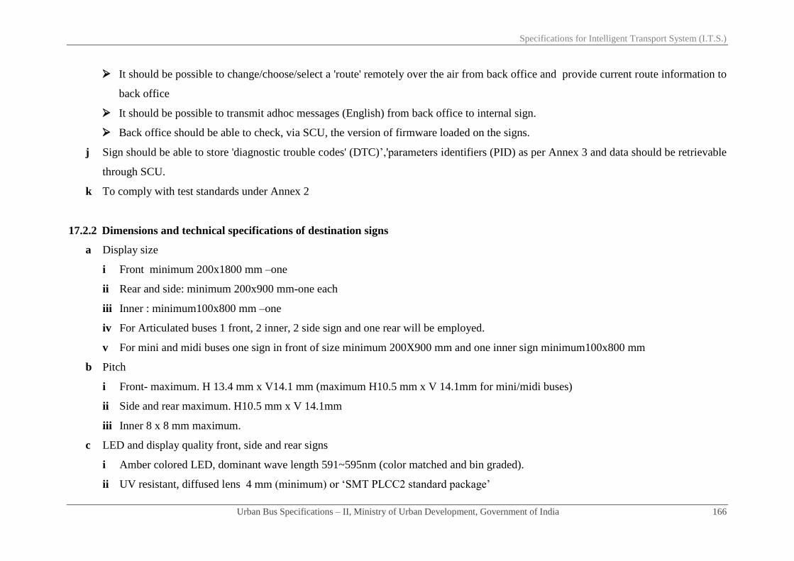
Specifications for Intelligent Transport System (I.T.S.)
Urban Bus Specifications – II, Ministry of Urban Development, Government of India 166
It should be possible to change/choose/select a 'route' remotely over the air from back office and provide current route information to
back office
It should be possible to transmit adhoc messages (English) from back office to internal sign.
Back office should be able to check, via SCU, the version of firmware loaded on the signs.
j Sign should be able to store 'diagnostic trouble codes' (DTC)’,'parameters identifiers (PID) as per Annex 3 and data should be retrievable
through SCU.
k To comply with test standards under Annex 2
17.2.2 Dimensions and technical specifications of destination signs
a Display size
i Front minimum 200x1800 mm –one
ii Rear and side: minimum 200x900 mm-one each
iii Inner : minimum100x800 mm –one
iv For Articulated buses 1 front, 2 inner, 2 side sign and one rear will be employed.
v For mini and midi buses one sign in front of size minimum 200X900 mm and one inner sign minimum100x800 mm
b Pitch
i Front- maximum. H 13.4 mm x V14.1 mm (maximum H10.5 mm x V 14.1mm for mini/midi buses)
ii Side and rear maximum. H10.5 mm x V 14.1mm
iii Inner 8 x 8 mm maximum.
c LED and display quality front, side and rear signs
i Amber colored LED, dominant wave length 591~595nm (color matched and bin graded).
ii UV resistant, diffused lens 4 mm (minimum) or ‘SMT PLCC2 standard package’

Specifications for Intelligent Transport System (I.T.S.)
Urban Bus Specifications – II, Ministry of Urban Development, Government of India 167
iii Wide viewing angle 120⁰ horizontal & 60⁰ Vertical
iv Ensure enhanced readability with full clarity on scrolls and long life usage by incorporating non multiplexed system (constant
current drive circuit) with typical LED Intensity 400~700 mCd at If =20 mA, alternatively multiplexed design (maximum 4:1) with
typical LED intensity 950~1150 mCd at 20 ma
d LED and display quality inner sign
i LED amber dot matrix viewing angle 45⁰ all around, intensity minimum 40 mCd, dominant wave length 590 ~595 nm
e Structure
i Front ,side and rear signs : light weight structure with toughened glass fixed with UV resistant adhesive in front
ii Inner sign: light weight structure with poly glass /acrylic/toughened glass.
iii Electronic devices used to be 'automotive grade' rated for temperature -25⁰C to +85⁰C (so as to meet tests specified in Annx 2) with
conformal coated PCB boards
iv Power to signs shall be supplied through bus multiplex wiring system
17.3 Automatic vehicle location (AVL) system
17.3.1 SCU will transmit raw GPS data ,of vehicle locations, in NMEA protocol , to back office control centre at user configurable frequency (
5 seconds or less),via 3G(GSM)/GPRS, for further processing and use ,including that for signs on bus stops ,BRTS and bus terminals.
17.4 Security camera network (SCN) system
17.4.1 Usability/Functionality/Capability
a The Network surveillance system shall consist of

Specifications for Intelligent Transport System (I.T.S.)
Urban Bus Specifications – II, Ministry of Urban Development, Government of India 168
i High resolution cameras, two numbers to monitor bus interiors (doors, driver zone, ticketing zone etc.) and one reversing surveillance
camera. For midi/mini buses 1 ambient and 1reversing and for articulated buses 3 ambient and 1 reversing camera to be employed.
ii Capability of 48 hour recording of images in ‘CIF’ mode (no sound) for total of four cameras. The recording will be overwritten if
not down loaded after the memory is fully utilized.
iii Capability to transfer the recordings to control centre/depot through SCU via high speed WLAN network (with back haul), in
compressed format
iv Capability to transfer the recordings using SD-card (if provided-refer 17.4.2 a below), tagged to vehicle ID, which is physically
removed and transferred to a card reader attached to the depot server.SD card will be provided in a lockable compartment.
v Capability to transfer recording using USB
b Recording functionalities
i Continuous or schedule based recording
ii Event based recording triggered by SCU (VHMD).
iii Event based recording triggered by sensors connected to the ‘recorder’(if provided separately)
iv Disconnected camera detection
v Auto shut down delay after ignition switch off
vi Auto reset after power break
vii Built in clock
viii Emergency operation: when activated by a foot operated micro pedal switch, the recording will take place at a preselected resolution
and FPS.
c SCU should be able to display on BDC one or more cameras at the same time upto maximum 4.
d BDC to display only reversing camera picture when reverse gear is engaged.

Specifications for Intelligent Transport System (I.T.S.)
Urban Bus Specifications – II, Ministry of Urban Development, Government of India 169
17.4.2 Architecture
a ‘Recording functionality’ could be provided in a ‘separate box (recorder)’ or alternatively could be in-built into SCU in which case hard
disc will be used instead of SD card for storage. The choice will be of the equipment supplier
b Power supply to ‘recorder’ will be provided through the bus multiplexing system.
c Power supply (12V regulated) to camera will be provided from
i ‘Recorder’.
ii Through the bus multiplexing system when ‘recording functionality’ is provided in SCU
17.4.3 Specifications
a ‘Camera’ specifications
i Fixed lens 3.6 mm
ii Picture resolution upto 752 H x 582 V (PAL),
iii Resolution = 420 TV lines minimum,
iv Picture sensor =1/3" CCD or better,
v IR distance 10 meters minimum ,
vi Automatic backlight compensation
vii Ingress protection rating IP66 minimum
b ‘Recorder’ specifications
i 4 Channel minimum
ii Recording resolution PAL
(1) CIF (352X288 ) upto 25 fps maximum each of 4 channel
Specifications for Intelligent Transport System (I.T.S.)
Urban Bus Specifications – II, Ministry of Urban Development, Government of India 170
(2) D1 (704X576) upto 25 fps maximum -one channels only
(3) DI (704X576) upto 12 fps maximum each of 4 channels,
iii Stream standards: ISO 1449, video compression standard H.264.
iv 48 hour (for total 4 channels) recording of images and voice in CIF mode.
17.4.4 Alternate system
IP (internet protocol) digital camera using ‘network recording' is also permitted with equal or better specifications.
17.5 Vehicle health monitoring and diagnostics (VHMD)
17.5.1 ‘SCU’ will receive vehicle health diagnostic data from multiplexing nodes and PIS signs
a The data from multiplexing nodes, on a single CAN 2B(JI939) bus will include parameters from
i Vehicle electrical system powered through multiplexing nodes
ii Vehicle safety and performance features
iii Engine and transmission
The list of such parameters is as per Annex 1. All ‘CAN’ parameters will be receivable in standard format "standardized message name, PGN,
SPN and rate.
b The data from PIS signs will include parameters specified in Annex 3
17.5.2 ‘SCU’ should be able to create log files and communicate to control centre at end of the day via WLAN the data related to parameters in
Annex 1.The log files will be overwritten if not down loaded.
17.5.3 SCU should be able to communicate to control centre, in case any of the parameters listed in Annex 1, exceed a predefined value at any
time .Such warning will also pop up real time on BDC screen. The number of such prompts will be five (maximum) at any time.

Specifications for Intelligent Transport System (I.T.S.)
Urban Bus Specifications – II, Ministry of Urban Development, Government of India 171
17.5.4 SCU should be able to display following parameters on BDC for viewing by driver/workshop technician.
a Engine oil pressure, engine coolant temperature, engine speed in RPM, vehicle speed.
b Transmission output shaft speed, transmission input shaft speed, transmission current gear, transmission oil filter restriction switch,
transmission oil life remaining, transmission service indicator, transmission sump oil temperature, transmission oil level high / low,
hydraulic retarder oil temperature
c ‘Nodes’ output status-parameters to be pre agreed at the time of tender.
d Vehicle performance/safety features such as brake condition ,door Interlock ,Kneeling interlock (wherever specified), gas leakage
detection (wherever specified), fire detection and suppression (wherever specified).The responsibility of providing requisite sensors for
such parameters rests with the OEM.
e Any other engine, transmission diagnostic data –parameters to be pre agreed at the time of tender.
17.5.5 SCU should be able to communicate to control centre, in real time, a pre selected 5 parameters (out of those mentioned above in 17.5.4).
17.6 On board hand held ticketing machine with smart card
17.6.1 Specifications
a As per MOUD letter k/14011/28/2009-metro (PT) dated 9th
may 2012.
b No compatibility required with SCU and OBITS
17.7 On board pole mounted smart card ticketing terminals
17.7.1 Specifications
a Two numbers, one each at two gates system. Specifications as per as per MOUD letter k/14011/28/2009-metro (PT) dated 9th may 2012.
17.7.2 Architecture
a SCU should be able to provide route, GPS information in XML format over TCP socket to ticketing machine.

Specifications for Intelligent Transport System (I.T.S.)
Urban Bus Specifications – II, Ministry of Urban Development, Government of India 172
b Ticketing machine should be able to connect through Ethernet port to enable it send information via the gateway on SCU. All such
transmission between ticketing machine and depot/CCC has to be 'secured' at the origin. Purchaser/operator shall make necessary
arrangement for identifying ticketing equipment and the protocol to be interfaced.
17.8 SCU and BDC architecture
17.8.1 Usability/Functionality/Capability
a Integrate and interface all features of
i Passenger information system (PIS)
ii Automatic vehicle location system (AVL)
iii Security camera network system (SCN)
iv Vehicle health monitoring and diagnostics (VHMD)
v On-board pole mounted ticketing machines
b Provide the driver/user interface/display on BDC as specified elsewhere in this document
c Display camera images on BDC as specified elsewhere in this document
d Control PIS functionality as specified elsewhere in the document
e Provide two-way voice and data link with control centre to communicate data and information as specified elsewhere in this document.
The link will be based on open public communications network services 3G (GSM) with downward compatibility with 2G
f Provide wireless LAN (WiFi) interface for wireless communications between the vehicle and depot network as specified elsewhere in
this document .This interface will not be available to passengers.
g Provide capability to upload firmware/ software and configuration of parameters on ‘SCU’ via the wireless LAN
h Provide audio interface to the driver’s microphone and earpiece or speaker using wired link to SCU (Telephone dial up is not envisaged)

Specifications for Intelligent Transport System (I.T.S.)
Urban Bus Specifications – II, Ministry of Urban Development, Government of India 173
i BDC ,on a selectable ‘menu’ will have ‘panic’ options’ for communicating pre configured messages to control centre
j Capability to store 'diagnostic trouble coded' (DTC)' ,'parameters identifiers (PID) as per Annex 3
k To comply with test standards under Annex 2
17.8.2 Technical specifications: SCU
a Processor : 32/ 64 bit
b Operating system: embedded Windows/Linux with programming software( Windows 7 or latest at the time of calling the tenders)
c Memory : flash: 2 GB minimum, RAM 512 MB minimum (RAM memory includes SCU and BDC)
d Interface : CAN 2.0, RS 485,RS 232, fast Ethernet, USB, digital outputs, digital/Analog inputs, WLAN, audio input output,, amplified
audio output
e Interface protocols :as specified elsewhere in this document
f In built GPS and 3G(GSM) modules
g WLAN
h Combi antenna using RG174 cable. The connectors on Combi antenna will be preferably SMA(M) ST plug type for GPS and FME(F)
jack type 1/4"-36UNS-2B for 3G
i In built /external two channel amplifier minimum 10 Watts rms each suitable for 4 ~8 Ohm impedance with input for external
microphone
j In-built MP3 files storage/playback function.
k Power to SCU & BDC will be supplied through bus multiplexing wiring system
17.8.3 Technical Specifications: BDC
a Display

Specifications for Intelligent Transport System (I.T.S.)
Urban Bus Specifications – II, Ministry of Urban Development, Government of India 174
i Size 5.7” diagonal minimum
ii Full color graphic TFT-640 x 480 dots minimum, capable of showing minimum 20 lines in English.
iii Viewing angle (horizontal) 60°/75° (right/left)/ (vertical) 60°/75° (up and down)
iv Adjustable back lighting
b Key board :4 keys minimum
17.8.4 Technical specifications: GPS modules
a Rating:22 tracking/66 acquisition minimum
b Tracking sensitivity :-165 dBm typ
c Navigation sensitivity ; -148 dBm typ
d Update rate I Hz (configurable to 10 Hz)
e Time to first fix cold acquisition 35 seconds typ
f Hot acquisition 1 second typ.
g Navigation accuracy 3M horizontal
17.8.5 Technical specifications: 3G(GSM) modules
a GSM/GPRS SMT quad band and UMTS (3G)
b Temperature range -40°C to +85°C
17.8.6 Technical specifications: ‘Combi’ Antenna
a AMPS 850MHz, GSM900MHz, ISM868MHz, DCS1800MHz, PCS1900MHz, 3G UMTS 2.1GHz, Wifi /Blue Tooth (2.4 GHz),GPS
(1575.42MHz). Separate WLAN antenna may be provided if necessary.
b GPRS

Specifications for Intelligent Transport System (I.T.S.)
Urban Bus Specifications – II, Ministry of Urban Development, Government of India 175
i Impedance 50 Ohm
ii Radiation pattern Omni-directional
iii Polarization linear (vertical)
c GPS
i Impedance 50 Ohms
ii VSWR <1.5:1
iii Polarization RHCP
d Waterproof IP-66
e Temperature range -40°C to +85°C
f RG174 cable
17.8.7 Fitment on bus
a All ‘OBITS’ equipment including wiring harness, antennas to be original factory fitment.
b Front, side, rear signs should be mounted with a gap with the glass so that the glass on signs and of the bus can be cleaned by swiping
c All equipment should be fitted in a way to minimize unintentional damage, shielded from direct engine heat, protected from water splash
and dust.
d All cables need to be properly anchored
e Others:
i Front sign: central
ii Rear sign: central
iii Side sign: first window ahead of rear door (central line of sign should coincide with central line of window)
iv Inner sign: centralize along the width of bus behind the driver's partition

Specifications for Intelligent Transport System (I.T.S.)
Urban Bus Specifications – II, Ministry of Urban Development, Government of India 176
v Speakers with protective grill : one each near the doors and others equally distributed across the length of the bus- Total no. 4
vi SCU, recorder, amplifier : secured and ventilated compartment right above the driver
vii BDC: ergonomically placed for driver ease
viii Camera: as specified else where
ix Ticketing machines - pole Mounted: as specified elsewhere
x Combi antenna: suitable place to define inside the bus (preferably) with direct line of view for 'affixing' the unit.
17.8.8 Communication amongst sub systems
a 'Signs' to 'SCU' RS 485
b 'Multiplexing nodes' to 'SCU' CAN 2B (J1939)
c 'Camera' to 'Recorder’ AVI or Ethernet (for ‘IP’ camera option )
d 'SCU to 'BDC' Ethernet/DVI/VGA/HDMI/RS232/RS485 as required.
e Add -on 'Ethernet switch' and CAN ports are permitted
17.8.9 Communication between SCU and depot/central control centre (CCC)
a AVL to CCC:
Raw GPS data in NMEA 0183 protocol (GPVTG, GPGGA, GPRMC, GPGSV and GPGSA) and route number via open public
communications network services 3G and download compatibility
b VHMD real time warning to CCC
Open public communications network services 3G and download compatibility
c VHMD end of the day to depot
IEEE 802.11 Wireless LAN (WiFi) via 'Back haul' at depot
d SCN 48 hour recording to depot

Specifications for Intelligent Transport System (I.T.S.)
Urban Bus Specifications – II, Ministry of Urban Development, Government of India 177
IEEE 802.11 Wireless LAN (WiFi) via 'Back haul' at depot plus SD card physical transfer/USB physical transfer
e Firmware download from Depot
IEEE 802.11 Wireless LAN (WiFi) via 'Back haul' at depot
f PIS Two way communication to depot need based, API to be pre-agreed
g Any protocol provided by ITS supplier will be under a 'NDA' amongst the parties
17.8.10Additional requirements of Purchaser/Operator
a If required, Purchaser/Operator can specify as a part of their tender requirements, unambiguously, any additional requirement in relation
to ‘interface’ with their ITS Infrastructure.
17.8.11TA' and 'COP' approvals
a The notified agencies, as under rule number 126 of CMVR, will be responsible for approvals and certification of 'OBITS' system as
defined above.
b Above approvals ,when accorded to sub system suppliers such as PIS ,SCU and BDC, etc will be valid across the board for various
purchaser/operator, OEMs and tenders
17.8.12 Warranties
a The standard warranty will be identical to the warranty of bus (up to 3 years maximum) however purchaser/operator may ask OEMs for
extended warranty /annual maintenance contract after expiry of standard warranty periods.
17.8.13 ITS Infrastructure at Purchaser/Operator
a Purchasers/Operator(s) are obligated to install the necessary ITS infrastructure and human resource to 'take over' the OBITS system from
OEMs and have their own cell for day to day operations and needs. Typical examples being: PIS route programming including voice
recordings ,maintaining up-to-date LAT LONG database, ‘Back Haul' operations.
b OEMs are obligated to provide training to such purchaser/operator(s) staff before delivery of buses.

Specifications for Intelligent Transport System (I.T.S.)
Urban Bus Specifications – II, Ministry of Urban Development, Government of India 178
c Driver Score Card/Driver rating: Purchasers/Operator(s) are obligated to make use of the information from OBITS to incorporate a
practice of ‘Driver Score Card’. A few suggested parameters are
I. Door Open while driving
II. Harsh Acceleration
III. Excessive Idling
IV. Harsh Braking
V. Over revving
VI. Over speeding
VII. Excessive Trip Mileage (Fuel Mileage)
VIII. Non Adherence to ‘Trip Schedule’ e.g. ‘Late Start’, ‘Off Route’ and ‘Duty Cycle’
IX. Driving with Faults: Warning Pop ups reported and initiative to get corrected
X. Panic Button usage
XI. Cameras switched off
XII. Internal Sign Switched off
Data from the above will be based on
VHMD Log files and SCN data downloaded at end of the day including Driver ID
Live AVL location transmitted from Bus.

Specifications for Intelligent Transport System (I.T.S.)
Urban Bus Specifications – II, Ministry of Urban Development, Government of India 179
Annexure 1: VHMD parameter list
All data will be provided by bus multiplexing node
1. Vehicle electrical system
All external and internal fixtures like passenger/driver compartment illumination and ITS equipment.
2. Vehicle safety and performance features
Fuel /Oil level/ Pressure
Braking pedal position
Accelerator pedal position and kick down
Brake pad condition and brake pedal temperature (in case of electronically controlled disc brakes)
Door interlock
Kneeling interlock (wherever provided)
Gas leakage detection (wherever provided)
Fire detection/suppression (wherever provided)
3. Engine
Engine CAN status
Engine oil pressure,
Engine coolant temperature,
Engine speed in RPM,
Vehicle speed (torque),
Diagnostic message (engine specific)

Specifications for Intelligent Transport System (I.T.S.)
Urban Bus Specifications – II, Ministry of Urban Development, Government of India 180
4. Transmission
Transmission CAN status
Transmission output shaft speed
Transmission input shaft speed
Transmission current gear
Transmission oil filter restriction switch
Transmission oil life remaining
Transmission service indicator
Transmission sump oil temperature
Transmission oil level high / low
Hydraulic retarder oil temperature
Accelerator pedal
Diagnostic message (transmission specific)
5. Diesel bus electronics data (list is indicative, to be finalized by respective purchasers/operators)
Drivers demand of engine torque percentage
Actual engine torque percentage
Engine and retarder torque
Engine speed

Specifications for Intelligent Transport System (I.T.S.)
Urban Bus Specifications – II, Ministry of Urban Development, Government of India 181
Source address controlling device
Engine starter mode
Engine demand torque percentage
Accelerator pedal 2 low Idle switch
Road speed limit status
Accelerator pedal kick down switch
Accelerator pedal low Idle Switch
Accelerator pedal position
Percent load at current speed
Remote accelerator pedal position
Accelerator pedal position 2
Vehicle acceleration rate limit status
Engine temperature
Engine coolant temperature
Fuel temperature
Engine oil temperature
Turbo oil temperature
Engine intercooler temperature
Engine intercooler thermostat opening
Engine fluid level pressure
Fuel delivery pressure

Specifications for Intelligent Transport System (I.T.S.)
Urban Bus Specifications – II, Ministry of Urban Development, Government of India 182
Extended crankcase blow by pressure
Engine oil level
Engine oil pressure
Crankcase pressure
Coolant pressure
Coolant level
6. CNG bus electronics data (list is indicative, to be finalized by respective purchaser/operators)
Engine control unit
Engine speed sensor
Atmospheric pressure sensor
Brake switch signal
EEPROM error
Vehicle speed sensor
Main relay main relay
Ignition switch
Fuel temperature sensor
Turbocharger boost pressure sensor
Boost pressure control
Accelerator pedal position sensor 1
Accelerator pedal position sensor 2

Specifications for Intelligent Transport System (I.T.S.)
Urban Bus Specifications – II, Ministry of Urban Development, Government of India 183
Analog/digital converter
Coolant temperature sensor
Fault lamp, engine control
Electric shutoff (ELAB)
Needle sensor
Secondary engine speed signal
engine speed sensor
Start-of-injection control
Injection timing solenoid valve
Voltage supply control units
Reference voltage
air temperature sensor
Control-collar travel sensor
Control-collar travel sensor
Test after running test
Control-collar travel sensor
Engine control unit
Misfire recognition

Specifications for Intelligent Transport System (I.T.S.)
Urban Bus Specifications – II, Ministry of Urban Development, Government of India 184
Annexure 2: Test Standard Compliance Document
These tests standard compliances are common to PIS signs/multiplexing nodes/controller/driver console
Sr. No Test standards compliance Specifications
1 Performance parametric test
Nine points, tri temperature/tri voltage- 18V, 27V, 32V,-25°C, room temperature,
+85°C test. At each test point the system will be powered on and shut down 5 times
as per the supplier’s designated procedure and thereafter evaluated for malfunction if
any
2 Cold IS 9000 (Part II/Sec 4)-1977 (reaffirmed 2004) at -25⁰C for 2 hours in ‘on’ condition
3 Dry heat IS 9000 (Part III/Sec 5)-1977: PIS Signs, SCU and Nodes at + 80⁰C for 16 hours in
‘on’ condition. BDC at + 80⁰C for 2 hours
4 Damp heat
IS 9000 (Part V/Sec 2)1981 at +25⁰C /+55⁰C, Humidity 95%, 24 hours for 6 cycles in
off condition. Functional test with power in ‘on’ condition at start of 2nd, 4th and 6th
cycle
5 Vibration standard AIS 012/AIS:062 -10g
Frequency 5~50Hz and return to 5Hz at a linear sweep period of 1
minute/complete sweep cycle and 10g at maximum frequency
Excursion -1.6 mm peak to peak over the specified frequency range
Test duration 60 minutes
Direction of vibration –X, Y, Z axis of device as it is mounted on the vehicle.
6 Dust and water ingress protection IS /IEC 60947-1:2004 in conjunction with IS/IEC 60529:2001– ‘PIS signs’ IP66,
‘SCU’ IP 65, ‘BDC’ IP65, ‘nodes’ IP54
7 Free fall IS 9000 (Part VII/Sec 4) Free fall at 500 mm ,(applicable to ‘nodes’ and ‘controllers’

Specifications for Intelligent Transport System (I.T.S.)
Urban Bus Specifications – II, Ministry of Urban Development, Government of India 185
Sr. No Test standards compliance Specifications
only)
8 Fire resistant
Regulation directive 95-28/EG dated 24-10-1995 horizontal Burning rate tested as
per ISO 3795 ,
Horizontal burning test HB as per UL 94 -1998 clause 7 ( for wire harness)
9 Reverse polarity protection without fuse The component must fulfil the function- and service life requirements after being
subjected to reversed polarity up to 27 V for 2 minutes.
10 Over voltage protection To ensure service life requirements and functionality. The component shall run for 60
minutes at 38V, without effecting the service life or function.
11 Insulation resistance
The Insulation résistance measured as per ISO 16750-2 with a voltage of 500 V dc shall not be less than 1Mega ohm.
12 Cranking voltage
The components shall have an electrical energy reserve that can handle voltage drop
during cranking. Component shall not reset during cranking-‘FSC B’. The supply
voltage during crank is 18.0 V for 40 ms. The test to be carried out as per ISO 7637
13 Load dump test on controller 123V ,8 Ohms 200ms pulse 5a as per standard ISO 7637-2
14 Salt spray test (AIS: 012/ IS10250) 96 hours
15 EMC/EMI
1.Electromagnetic radiation, radiated immunity and compatibility as per AIS 004 (Part 3) or
2.72/245/EEC last amended by 2009/19/EC (includes 2004/104/EC, 2005/83/EC,
2006/96/EC) and UN ECE Regulation Number 10 Rev 3:2008

Specifications for Intelligent Transport System (I.T.S.)
Urban Bus Specifications – II, Ministry of Urban Development, Government of India 186
Sr. No Test standards compliance Specifications
Note: In case of product is ‘e’ marked and a detailed test report is submitted (which
includes above tests) no fresh verification is necessary
16 Operating parameters Supply voltage 24 V± 25%
17
LED color test – dominant wave length
amber AIS -012
18
LED chromaticity coordinates
Limit towards green: y ≤ x-0.120
Limit towards red: y ≥ 0.390
Limit towards white: y ≥ 0.790-0.670x
In accordance with CIE 127 condition B
19 LED bulb/SMT intensity and viewing
angle In accordance with CIE 127 condition B

Specifications for Intelligent Transport System (I.T.S.)
Urban Bus Specifications – II, Ministry of Urban Development, Government of India 187
Annexure 3: Diagnostic trouble codes (DTC) and Parameter Identifiers (PID) list
Appendix 1 – DTC code list of PIS signs
DTC code Description
1 2 0 0 Over voltage
1 2 0 1 Low voltage
1 2 0 3 Over heat
Appendix 1.1 – PID code list of PIS signs
Example of PIDs code numbers for a LED sign. PIN code is Ascii characters.
PID code Description
100 Hardware revision
101 Serial number
102 Boot loader SW revision
103 Application SW revision
104 Font library revision
105 CPU part number

Specifications for Intelligent Transport System (I.T.S.)
Urban Bus Specifications – II, Ministry of Urban Development, Government of India 188
PID code Description
106 CPU qualification
107 CPU temperature range
108 Compilation of FW date and time
109 Flash update status
110 Test date and time
114 Article number sign level
115 Production date (production date)
116 End customer
117 Order number
118 Bus/vehicle type
119 Bus builder number (bus build)
208 Language
401 Board temp sensor
402 Internal CPU temp
600 Minimum temp CPU

Specifications for Intelligent Transport System (I.T.S.)
Urban Bus Specifications – II, Ministry of Urban Development, Government of India 189
PID code Description
601 Maximum temp CPU
602 Maximum temp board
603 Minimum temp board
604 Maximum input power voltage
605 Minimum input power voltage
606 Operating hours
607 Number of resets
Appendix 1.2 – DTC code list of controller
DTC code Comments
0 0 1 2 Watch dog reset
0 0 1 3 Low voltage reset
0 0 2 0 Lost communication, GPS satellite (GPS receiver is not available to the system.)
0 0 2 1 Invalid data, GPS signal invalid
0 0 2 2 GPS antenna error

Specifications for Intelligent Transport System (I.T.S.)
Urban Bus Specifications – II, Ministry of Urban Development, Government of India 190
0 0 2 5 USB, invalid USB mass storage device
0 0 2 6 USB, unknown USB device connected
0 0 2 7 USB, USB invalid file system
0 0 0 7 USB, overcurrent
0 2 0 0 Over voltage
0 2 0 1 Low voltage
0 2 0 3 Over heat
Appendix 1.3 – PID code list controller
Example of PIDs code numbers for control unit. PIN code is Ascii characters.
PID code Description
100 Hardware revision
.i101 Serial number
102 Boot loader SW revision
103 Application SW revision
104 Font library revision

Specifications for Intelligent Transport System (I.T.S.)
Urban Bus Specifications – II, Ministry of Urban Development, Government of India 191
105 CPU part number
106 CPU qualification
107 CPU temperature range
108 Compilation of FW date and time
110 Test date and time

Windshield Designs
Annexure - 1

Annexure – 01: Windshield Designs
Urban Bus Specifications – II, Ministry of Urban Development, Government of India

Annexure – 01: Windshield Designs
Urban Bus Specifications – II, Ministry of Urban Development, Government of India

Annexure – 01: Windshield Designs
Urban Bus Specifications – II, Ministry of Urban Development, Government of India

Annexure – 01: Windshield Designs
Urban Bus Specifications – II, Ministry of Urban Development, Government of India
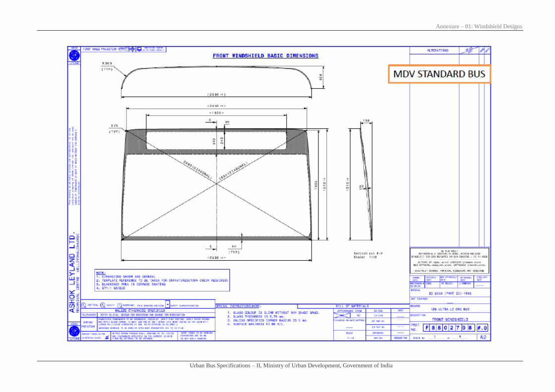
Annexure – 01: Windshield Designs
Urban Bus Specifications – II, Ministry of Urban Development, Government of India

Annexure – 01: Windshield Designs
Urban Bus Specifications – II, Ministry of Urban Development, Government of India

Annexure – 01: Windshield Designs
Urban Bus Specifications – II, Ministry of Urban Development, Government of India

Annexure – 01: Windshield Designs
Urban Bus Specifications – II, Ministry of Urban Development, Government of India

Annexure – 01: Windshield Designs
Urban Bus Specifications – II, Ministry of Urban Development, Government of India

Annexure – 01: Windshield Designs
Urban Bus Specifications – II, Ministry of Urban Development, Government of India

Figures
Annexure - 2

Annexure – 02: Figures
Urban Bus Specifications – II, Ministry of Urban Development, Government of India
Figure - 01

Annexure – 02: Figures
Urban Bus Specifications – II, Ministry of Urban Development, Government of India
Figure - 02

Annexure – 02: Figures
Urban Bus Specifications – II, Ministry of Urban Development, Government of India
12 m BRT Standard Bus
(Refer guideline for how to select doors and width)

Annexure – 02: Figures
Urban Bus Specifications – II, Ministry of Urban Development, Government of India
(Guidelines for how to select door location) 12 m BRT Standard Bus
Station Door Details
Bus Gates Details Platform Ht
Operation Option Options for Bus Gate Locations for
station position Description
900
Near Side Off Side
Front Middle Rear Middle
I BRTS with dedicated corridor only
with stations on either side
Near Side Gates A B C
N/A
Width of Door
Option 1 800 1200 (N/A) 1200 (N/A)
Option 2 1200 1500
Option 3 1200/1200 *
Steps Required Y/N If Y,
then no of Steps (No) Y (2) N N
Off Side Gates
N/A
D
Width Option 1 1200/1200 *
Steps Required Y/N N
II
BRTS with BRT corridor + extn in
Mixed Traffic (Off Side -Level
Boarding + Near Side - non-level
boarding)
Near Side Gates A B C
N/A
Width of Door
Option 1 800 1200 (N/A) 1200
Option 2 1200 1500 (N/A)
Option 3 1200/1200 (N/A)
Steps Required Y/N If Y,
then no of Steps (No) Y (2) N Y (2)
Off Side Gates
N/A
D
Width Option 1200/1200 *
Steps Required Y/N N
Note: * There are two doors with partition as per specification

Annexure – 02: Figures
Urban Bus Specifications – II, Ministry of Urban Development, Government of India
18 m BRT Articulated Bus
(Refer guideline for how to select doors and width)

Annexure – 02: Figures
Urban Bus Specifications – II, Ministry of Urban Development, Government of India
(Guidelines for how to select door location) 18 m BRT Articulated Bus
Station Door Details
Bus Gates Details Platform Ht
Operation Option
Options for Bus Gate
Locations for station
position
Description
900
Near Side Off Side
Front Tractor Trailer Tractor Trailer
I
BRTS with dedicated
corridor only with
stations on either side
Near Side Gates A B C
N/A
Width of Door
Option 1 800 1200/1200 * 1200
Option 2 1200 1500
Option 3 800/800 *
Steps Required Y/N If Y, then no of Steps
(No) Y (2) N N
Off Side Gates
N/A
E D
Width of Door
Option 1 1200/1200 * 800/800 *
Option 2 1500
Steps Required Y/N N N
II
BRTS with BRT
corridor + extn in Mixed
Traffic (Off Side -Level
Boarding + Near Side -
non-level boarding)
Near Side Gates A BC D
N/A
Width Option
Option 1 800 1200/1200 (N/A) 1200
Option 2 1200 1500 (N/A)
Option 3
800/800
(N/A)
Steps Required Y/N Y (2) Y (2)
Off Side Gates
N/A
FG E
Option 1 1200/1200 * 800/800 *
Option 2 1500
Steps Required Y/N N N
Note: * There are two doors with partition as per specification

Annexure – 02: Figures
Urban Bus Specifications – II, Ministry of Urban Development, Government of India
25 m BRT Bi-Articulated Bus
(Refer guideline for how to select doors and width)

Annexure – 02: Figures
Urban Bus Specifications – II, Ministry of Urban Development, Government of India
(Guidelines for how to select door location) 25 m BRT Bi- Articulated Bus
Station Door Details
Bus Gates Details Platform Ht
Operation Option
Options for Bus
Gate Locations for
station position
Description
900
Near Side Off Side
Front Tractor Trailer
1 Trailer 2 Tractor
Trailer
1
Trailer
2
I
Near Side Gates A B C D
N/A
Width of Door
Option 1 800 1200/1200 1200 800/800
Option 2 1200 1500
Steps Required Y/N If Y, then no of
Steps (No) Y (2) N N N
Off Side Gates
N/A
G F E
Width Option 1
Option 1 1200/1200 1200 800/800
Option 2 1500
Steps Required Y/N N N N
II
Near Side Gates A B C D
N/A
Width Option
Option 1 800 1200/1200 (N/A) 1200
Option 2 1200 1500 (N/A)
Option 3 800/800 (N/A)
Steps Required Y/N Y (2) N Y (2) N
Off Side Gates
N/A
G F E
Width Option 1
Option 1 1200/1200 1200 800/800
Option 2 1500
Steps Required Y/N N N N
Design Type Approval
Annexure - 3
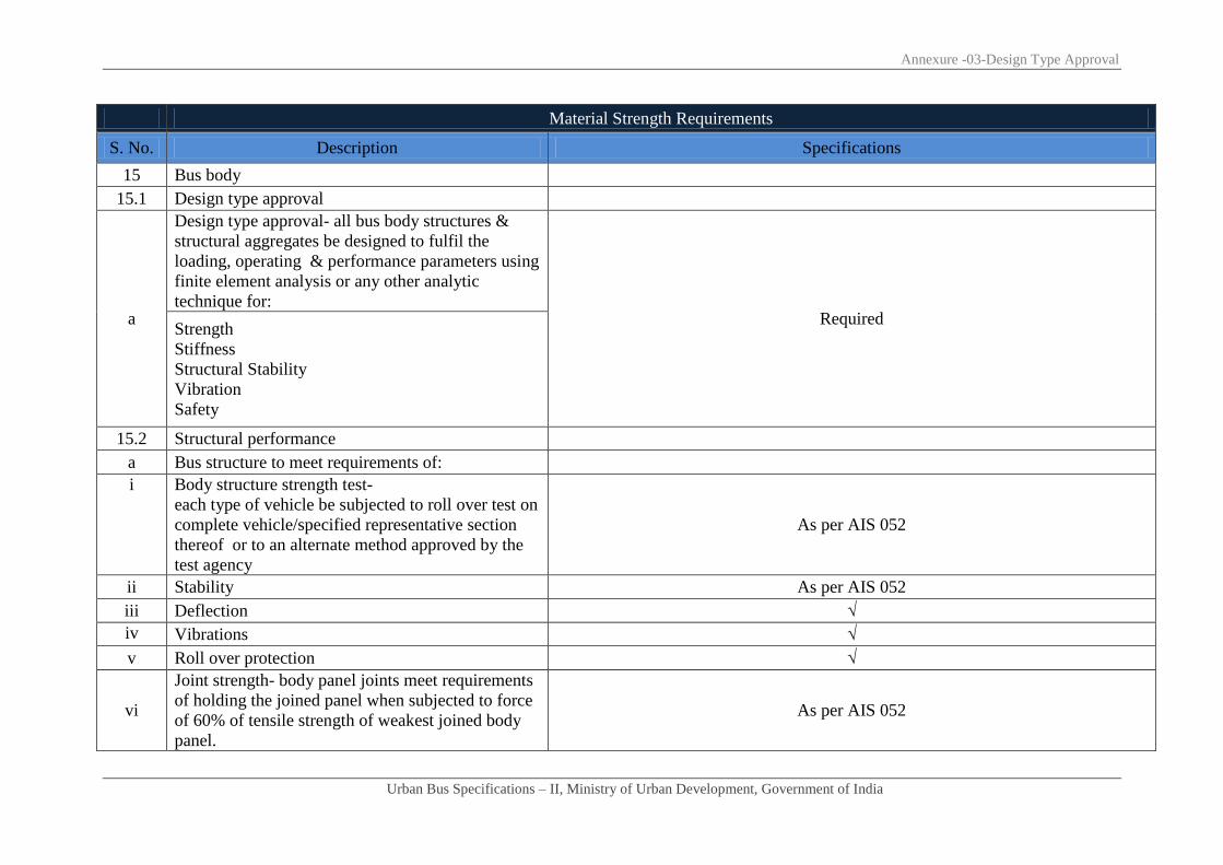
Annexure -03-Design Type Approval
Urban Bus Specifications – II, Ministry of Urban Development, Government of India
Material Strength Requirements
S. No. Description Specifications
15 Bus body
15.1 Design type approval
a
Design type approval- all bus body structures &
structural aggregates be designed to fulfil the
loading, operating & performance parameters using
finite element analysis or any other analytic
technique for: Required
Strength
Stiffness
Structural Stability
Vibration
Safety
15.2 Structural performance
a Bus structure to meet requirements of:
i Body structure strength test-
each type of vehicle be subjected to roll over test on
complete vehicle/specified representative section
thereof or to an alternate method approved by the
test agency
As per AIS 052
ii Stability As per AIS 052
iii Deflection √
iv Vibrations √
v Roll over protection √
vi
Joint strength- body panel joints meet requirements
of holding the joined panel when subjected to force
of 60% of tensile strength of weakest joined body
panel.
As per AIS 052

Annexure -03-Design Type Approval
Urban Bus Specifications – II, Ministry of Urban Development, Government of India
Material Strength Requirements
S. No. Description Specifications
b Various loads:
i
Normal loads (static) = Number of
Passenger*weight of Passenger (68 Kgs.) +
Passenger luggage weight (7 Kgs). (Besides the
vehicle related loads).
√
ii
Bump loads: # Bump height = As per relevant
BIS/Indian Road Congress guidelines. # Case I:
single wheel on bump/pot hole. # Case II:
diagonally opposite wheels on Bump/Pot hole. #
Case III: both wheels (front & rear) on bump/pot
hole.
√
iii Braking loads: 0.6g (applied together). Horizontal =
0.6g load, Vertical = 1g load √
c Bus body structure evaluation by a & or b As under
i Physical testing or As per AIS 052
ii Finite element method As per AIS 052
d Required performance values/data (minimum) for
above load conditions: As under
i Strength (factor of safety) (tolerance -10%) ≥ 3 i.e. design stress ≥ 1/3rd
of yield stress
ii Stiffness (deflection) mm 5mm
iii Vibrations (lowest natural frequency) hertz 5Hz
iv
Roll over tests with the bus rolling from ground
level instead of a raised platform. Angular velocity
should not exceed 5 degrees/second. All other
procedure as per AIS031 (i) Unstable position should not occur before 35⁰. ( ii) No part of structure intrudes
into residual space. 1. Bus tilted to its unstable position
2. Bus allowed falling freely under gravity from this

Annexure -03-Design Type Approval
Urban Bus Specifications – II, Ministry of Urban Development, Government of India
Material Strength Requirements
S. No. Description Specifications
position.
3. GVW of the bus to be considered
v
4. Energy absorbed by the structure {ER =Reference
energy-- potential energy of the bus in its (unstable)
equilibrium position). ER = M*g*h Where M=
Effective weight of the bus, g = Acceleration due to
gravity, h= Height of C.G. above ground level in
(unstable) equilibrium position.}.
0.75 ER
vi Buckling factor ≥ 4

Test procedure for evaluation of AC system
performance
Annexure - 4

Annexure -04-Bus AC Test Procedure
Urban Bus Specifications – II, Ministry of Urban Development, Government of India
1.0 Scope:-
This test procedure is applicable for testing the Air Conditioning system performance at hot ambient and very hot ambient condition on
intracity urban bus in a climatic hot chamber. This procedure does not cover durability aspects of Air conditioning system.
2.0 Test Conditions:-
2.1 The performance of bus air conditioning system is evaluated in the following operating conditions
2.2 Test shall be carried out in climatic hot chamber, on stationary bus in neutral (gear)
2.3 Test RPM: Average of two corresponding engine RPM correlated to vehicle speed of 40 KMPH for two successive gears recommended
by the manufacturer. Test RPM shall have a tolerance of + 50 RPM
2.4 AC Control Settings:-
a) Blower speed : Maximum speed
b) Temperature control : Maximum cooling
c) Air intake : Recirculation mode
d) Mode button : Cooling
2.5 Environment / Ambient condition:-
a) Ambient Temperature : 42±2°C (Hot ambient_Test Condition 1)
: 48±2°C (Very hot ambient_Test Condition 2)
b) RH : 40±5% for both test conditions.
2.6 Test Duration:-
a) Hot soaking time : 90 minutes.

Annexure -04-Bus AC Test Procedure
Urban Bus Specifications – II, Ministry of Urban Development, Government of India
b) Test duration after start of : 30 minutes (Hot ambient_Test Condition1)
engine and AC system 40 minutes (Very hot ambient_Test condition2)
3.0 Test Procedure:-
3.1 The bus under test shall be instrumented for the air conditioning performance evaluation (refer Annexure A for instrumentation inside
the bus).
3.2 After instrumentation is complete, the bus shall be parked inside the climatic hot chamber with the front end facing the wind simulation
fan. Engine and AC system is OFF.
3.3 If bus is equipped with a heating system, ensure the bus heating system is switched off during the trials. If bus is equipped with
automatic temperature control, then ensure ‘cooling’ mode is selected.
3.4 The climatic hot chamber shall be started.
3.5 The environment / ambient conditions to be set inside the hot chamber shall be as per Para 2.
3.6 Allow the hot chamber to attain temperature of 42±2°C (Test condition 1) / 48±2°C (Test condition 2).
3.7 When above chamber condition is reached doors of the bus shall be kept open. This indicates start of hot soaking of the bus.
3.8 Hot soak the bus for 90 minutes.
3.9 After hot soaking of 90 minutes the driver and two test engineers shall enter the bus and close the doors.
3.10 Initial temperature at nose level of all passenger seat locations shall be recorded before starting engine and AC system.
3.11 Engine shall be started and AC controls are to be set as described in Para 2.5. AC system is switched ON. This indicates start of the test
3.12 Wind simulation fan shall be started.

Annexure -04-Bus AC Test Procedure
Urban Bus Specifications – II, Ministry of Urban Development, Government of India
3.13 Nose level temperature at all passenger seat locations shall be recorded at 1 minute intervals for entire test duration (i.e. 30 minutes for
Test condition1 and 40 minutes for test condition 2)
3.14 Air velocity at vents provided above passenger seats shall be measured at the end of the test.
3.15 After the test is complete, the air velocity data recorded and the temperature data recorded shall be presented in a format shown in
Annexure B. Extract average passenger nose level temperature and average vent air velocity.
3.16 Average Passenger Nose Level Temperature (in °C) vs. Time (in minutes) graph shall be extracted from the test data.
3.17 From the above graph determine the average passenger nose temperature at 30th
minute (Test condition 1) / 40th
minute (Test condition
2)
4. 0 Acceptance criteria:
Bus AC system performance shall be considered acceptable if it complies as below:
4.1 Air velocity:-
The average air velocity measured at vents provided above passenger seats as described in Para 3.14 should be at least 4.5 m/s.
4.2 Average passenger nose level temperature:-
Hot ambient_Test condition 1:
The bus air conditioner should achieve average passenger nose level temperature of 24±4°C in 30 minutes
Very hot ambient_Test condition 2:
The bus air conditioner should achieve average passenger nose level temperature of 33°C in 40 minutes

Annexure -04-Bus AC Test Procedure
Urban Bus Specifications – II, Ministry of Urban Development, Government of India
Annexure A
Instrumentation Inside Bus – Sample Format
A
nn
ex
ure
7
Th
erm
oc
ou
ple
la
yo
ut
ins
ide
bu
s
To
tal m
ea
su
rem
en
t p
oin
ts -
21
EM
ER
G
DO
OR
DO
OR
1
2313
14
15
16 8
910
11
12
17
18
19
20
21
22
23
31
24
25
26
27
35
36
34
28
29
30
45
67
DO
OR
2
32
33
N1
N2
N3
N11
N10
N12
N21
Nose T
herm
ocouple
N4
N6
N8
N5
N7
N9
N13
N15
N17
N19
N14
N16
N18
N20
TOP
VIE
W
FRO
NT
VIE
W
FRO
NT
OF
BU
S
Bu
s Fl
oo
r Le
vel
10
40
5
50
0
Pas
sen
ger
RH
P
asse
nge
r LH
10
40
5
K Type Thermocouples VIEW FROM FRONT END OF BUS

Annexure -04-Bus AC Test Procedure
Urban Bus Specifications – II, Ministry of Urban Development, Government of India
Ambient Temperature: Date:
RH:
N1 N2 N3 N4 N5 N6 N7 N8 N9 N10 N11 N12 N13 N14 N15 N16 N17 N18 N19 N20 N210.0
1.0
2.0
3.0
4.0
5.0
6.0
7.0
8.0
9.0
10.0
11.0
12.0
13.0
14.0
15.0
16.0
17.0
18.0
19.0
20.0
21.0
22.0
23.0
24.0
25.0
26.0
27.0
28.0
29.0
30.0
Air
velocity at
vent (m/s)
Avg.
Temp
Passenger nose level temperature (°C)
AC Performance Test on Bus
Time
(min)
Avg Vel
Anexure B
AC Performance Test - Sample Format
* Continue recording the temperatures till 40th minute for Test Condition 2

List of participants of “Urban Bus Committee”
Annexure - 5

Annexure – 03: List of participants of Urban Bus Committee
Urban Bus Specifications – II, Ministry of Urban Development, Government of India
List of participants of “Urban Bus Committee”
S. No. Urban Bus Committee Member Designation
1 OSD (UT) & e o. JS, M/O UD Chairman
2 Representative from D/O Heavy Industries Member
3 Representative from M/o Road Transport & Highways Member
4 DG, BPR & D Member
5 MD, DTC Member
6 MD, BMTC Member
7 Director General SIAM Member
8 President , ASTRU Member
9 Director, ARAI Member
10 Director, CIRT Member
11 Prof H M Shivanand Swamy,Executive Director CEPT Member
12 DG, IUT Member
13 Mr. Ajai Mathur, MD, UMTC Convenor
14 Laghu Parashar, UMTC Member
15 Manjiri Akalkotkar, CEPT Member
16 Vivek Ogra, VbSoft Member
17 Amit Bhatt, Embarq Member
18 Director, Gets Technology Solutions Pvt. Ltd. Member
19 Executive Director, Castmaster Group Member
20 One Representative from Tata Motors Ltd Member
21 One Representative from Ashok Leyland Member
22 One Representative from Swaraj Mazda Ltd Member
23 One Representative from Volvo Buses Ltd Member
24 One Representative from JCBL Ltd Member
25 One Representative from Eicher Motors Ltd Member
26 One Representative from Sutlej Motors Ltd Member
27 One Representative from Corona Bus Manufacturer Ltd Member
28 One Representative from Mercedes Benz India Ltd Member
29 One Representative from Mahindra Navi Star Automotives Ltd. Member

Ministry of Urban Development
Government of India
www.moud.gov.in
April, 2013
Recommendatory
Urban Bus Specifications – II