27. urban bus specifications
TRANSCRIPT


COMMITTEE ON UBS
CORE GROUP ON UBS
CORE GROUP ON UBS
• Professionals/ Experts•OEMs-Bus, ITS•Asso. of bus body builders•SIAM•ASRTU•CIRT & ARAI• Operators (BMTC, DTC etc)

Comfortable & Safe for Passenger Accessible for PWD’s Better Driving Conditions Standardization of common specifications
• Regular and BRTS services Technological advancements ITS enabled Value for money

Type Floor Ht. Length Width Total Capacity
Standard 650 mm 12 m 2.6 m 70
Midi 400/650mm 9 m 2.5 m 40
Mini 900 mm 6 m 2.2 m 22
Standard BRTS 900 mm (max) 12 m 2.6 m 70
Arti-BRTS 900 mm (max) 18 m 2.6 m 110
Bi-Articulated In Process
High end In Process

Pneumatic controlled wider doors Wider gangway ≥ 700mm Higher acceleration ≥ 0.8m/s/s Engine location & fuel: optional ROH ≤ 50% of Wheel base Approach & departure angle: 8.5˚ & 9˚ Life cycle: 10 years & 750,000 kms

Gangway
ROH


Transmission system Standards for driver’s area
• Noise• Vibration and • Heat

Mandatory door closure for movement of bus
Disc brakes Design Type approval: Roll over test

To be evolved for 650/900mm floor ht ???

Multiplex wiring Vehicle Health Monitoring system Driver Console PIS inside and outside integrated with
audio announcement system Camera (inside & rear)

1. Floor inside the bus should be uniform inside the vehicle without any steps inside vehicle
2. Floor Height of the Vehiclea) 400, 650 and 900 mm if meets criteria above 1.


Drive & Non driver side door for median & side station @ 400/650/900 mm ht to match BRTS platform heightPartition between doors for both Driver and Non driver side Tractor GateExtra optional front Non Driver side gate with steps
DIAGRAM FOR ILLUSTRATION ONLYNot to Scale

3. Station Locationa) Median Station with platform height to match bus floor
height for BRTS operationb) Side Station with platform height to match bus floor height
for BRTS operation3. System may have all Median stations or all Side Stations
or combinations of Median and Side station with platform height 400 /650 / 900 mm to meet the floor height of the vehicle.
4. Vehicle door locations and floor height selection will be based on the design of BRTS element design – station location, platform height and the local conditions.
15

Door with steps for end terminals & open operationCan also act as emergency door
Single Wide door in center for faster dispersal- for operating only in the BRT corridorStep-less align with bus stop platform easy access for wheel chair user

Uniform floor height across the length Step less movement inside the bus Easy & fast dispersal of passenger across the length of the bus- lesser dwell time
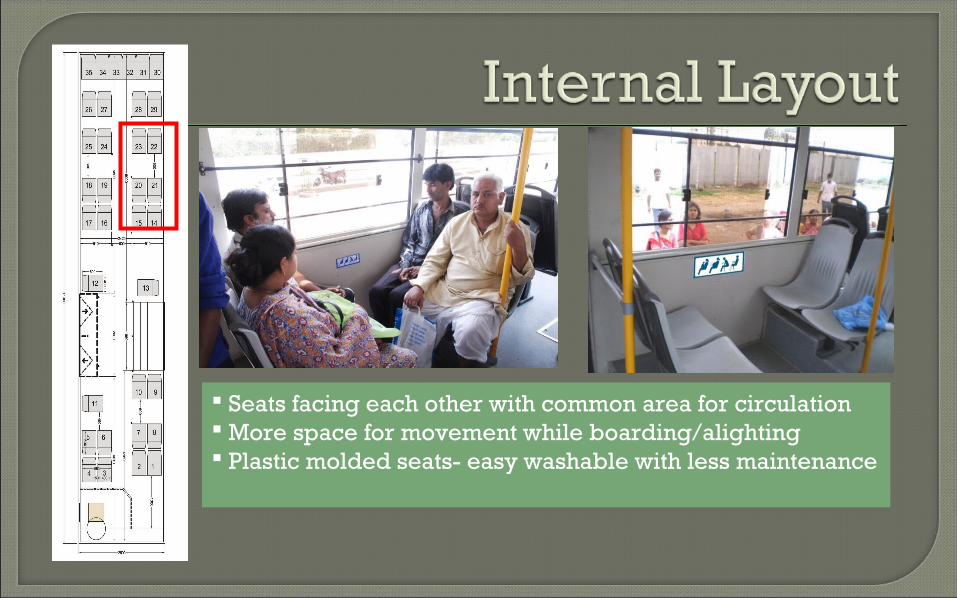
Seats facing each other with common area for circulation More space for movement while boarding/alighting Plastic molded seats- easy washable with less maintenance
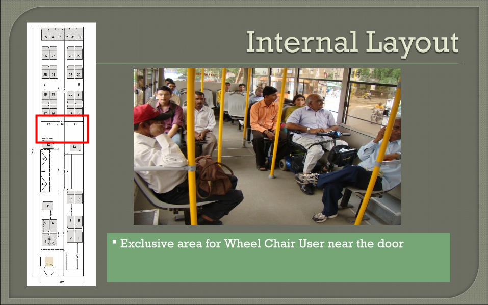
Exclusive area for Wheel Chair User near the door
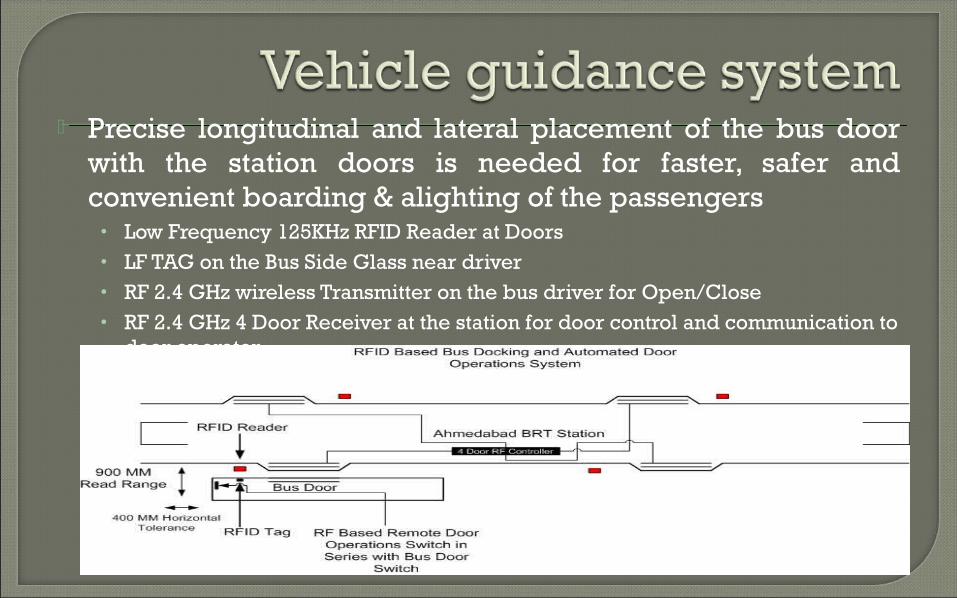
Precise longitudinal and lateral placement of the bus door with the station doors is needed for faster, safer and convenient boarding & alighting of the passengers
• Low Frequency 125KHz RFID Reader at Doors• LF TAG on the Bus Side Glass near driver• RF 2.4 GHz wireless Transmitter on the bus driver for Open/Close• RF 2.4 GHz 4 Door Receiver at the station for door control and communication to
door operator

RFID Tag
Precise & safe docking with the bus stop platform

Limited Bus Manufacturers Capacity for maintenance Unaffordable AMC No standards on fuel efficiency of buses ARAI approval is limited to ‘chassis’ only No standards to check on performance of AC
buses Standardization Station layout wrt door
locations
