recommendation l.100/l.10 (05/2021) – optical fibre cables
TRANSCRIPT
I n t e r n a t i o n a l T e l e c o m m u n i c a t i o n U n i o n
ITU-T L.100/L.10 TELECOMMUNICATION STANDARDIZATION SECTOR OF ITU
(05/2021)
SERIES L: ENVIRONMENT AND ICTS, CLIMATE CHANGE, E-WASTE, ENERGY EFFICIENCY; CONSTRUCTION, INSTALLATION AND PROTECTION OF CABLES AND OTHER ELEMENTS OF OUTSIDE PLANT
Optical fibre cables – Cable structure and characteristics
SERIES L: ENVIRONMENT AND ICTS, CLIMATE CHANGE, E-WASTE, ENERGY EFFICIENCY; CONSTRUCTION, INSTALLATION AND PROTECTION OF CABLES AND OTHER ELEMENTS OF OUTSIDE PLANT
Optical fibre cables – Cable structure and characteristics
Optical fibre cables for duct and tunnel application
Recommendation ITU-T L.100/L.10
ITU-T L-SERIES RECOMMENDATIONS
ENVIRONMENT AND ICTS, CLIMATE CHANGE, E-WASTE, ENERGY EFFICIENCY; CONSTRUCTION,
INSTALLATION AND PROTECTION OF CABLES AND OTHER ELEMENTS OF OUTSIDE PLANT
OPTICAL FIBRE CABLES
Cable structure and characteristics L.100–L.124
Cable evaluation L.125–L.149
Guidance and installation technique L.150–L.199
OPTICAL INFRASTRUCTURES
Infrastructure including node elements (except cables) L.200–L.249
General aspects and network design L.250–L.299
MAINTENANCE AND OPERATION
Optical fibre cable maintenance L.300–L.329
Infrastructure maintenance L.330–L.349
Operation support and infrastructure management L.350–L.379
Disaster management L.380–L.399
PASSIVE OPTICAL DEVICES L.400–L.429
MARINIZED TERRESTRIAL CABLES L.430–L.449
E-WASTE AND CIRCULAR ECONOMY L.1000–L.1199
POWER FEEDING AND ENERGY STORAGE L.1200–L.1299
ENERGY EFFICIENCY, SMART ENERGY AND GREEN DATA CENTRES L.1300–L.1399
ASSESSMENT METHODOLOGIES OF ICTS AND CO2 TRAJECTORIES L.1400–L.1499
ADAPTATION TO CLIMATE CHANGE L.1500–L.1599
LOW COST SUSTAINABLE INFRASTRUCTURE L.1700–L.1799
For further details, please refer to the list of ITU-T Recommendations.

Rec. ITU-T L.100/L.10 (05/2021) i
Recommendation ITU-T L.100/L.10
Optical fibre cables for duct and tunnel application
Summary
Recommendation ITU-T L.100/L.10 describes characteristics, construction, test methods and
performance criteria of optical fibre cables installed by pulling method for duct and tunnel application.
Note that Recommendation ITU-T L.10, Ed 3.0, was redesignated as ITU-T L.100/L.10, Ed 3.0, in
February 2016.
First, in order to demonstrate sufficient performance of an optical fibre, the characteristics that a cable
should possess are described. Then, the methods of examining whether a cable has the required
characteristics are described. Therein, detailed performance criteria for a cable are recommended.
Recommended technical requirements are detailed by reference to IEC 60794-3-11 on outdoor optical
fibre cables for duct, directly buried, and lashed aerial applications. Changes and additions to these
requirements suitable to the duct and tunnel cable application are recommended herein.
Required conditions may differ from the installation environment. Therefore, instances where
agreement on detailed conditions should be determined between customer and manufacturer are stated.
History
Edition Recommendation Approval Study Group Unique ID*
1.0 ITU-T L.10 1988-11-25 11.1002/1000/1414
2.0 ITU-T L.10 2002-12-22 6 11.1002/1000/6134
3.0 ITU-T L.100/L.10 2015-08-13 15 11.1002/1000/12532
4.0 ITU-T L.100/L.10 2021-05-29 15 11.1002/1000/14631
Keywords
Optical fibre cable, duct, tunnel, mechanical characteristics, environmental condition, test method.
* To access the Recommendation, type the URL http://handle.itu.int/ in the address field of your web
browser, followed by the Recommendation's unique ID. For example, http://handle.itu.int/11.1002/1000/
11830-en.

ii Rec. ITU-T L.100/L.10 (05/2021)
FOREWORD
The International Telecommunication Union (ITU) is the United Nations specialized agency in the field of
telecommunications, information and communication technologies (ICTs). The ITU Telecommunication
Standardization Sector (ITU-T) is a permanent organ of ITU. ITU-T is responsible for studying technical,
operating and tariff questions and issuing Recommendations on them with a view to standardizing
telecommunications on a worldwide basis.
The World Telecommunication Standardization Assembly (WTSA), which meets every four years, establishes
the topics for study by the ITU-T study groups which, in turn, produce Recommendations on these topics.
The approval of ITU-T Recommendations is covered by the procedure laid down in WTSA Resolution 1.
In some areas of information technology which fall within ITU-T's purview, the necessary standards are
prepared on a collaborative basis with ISO and IEC.
NOTE
In this Recommendation, the expression "Administration" is used for conciseness to indicate both a
telecommunication administration and a recognized operating agency.
Compliance with this Recommendation is voluntary. However, the Recommendation may contain certain
mandatory provisions (to ensure, e.g., interoperability or applicability) and compliance with the
Recommendation is achieved when all of these mandatory provisions are met. The words "shall" or some other
obligatory language such as "must" and the negative equivalents are used to express requirements. The use of
such words does not suggest that compliance with the Recommendation is required of any party.
INTELLECTUAL PROPERTY RIGHTS
ITU draws attention to the possibility that the practice or implementation of this Recommendation may involve
the use of a claimed Intellectual Property Right. ITU takes no position concerning the evidence, validity or
applicability of claimed Intellectual Property Rights, whether asserted by ITU members or others outside of
the Recommendation development process.
As of the date of approval of this Recommendation, ITU had not received notice of intellectual property,
protected by patents/software copyrights, which may be required to implement this Recommendation.
However, implementers are cautioned that this may not represent the latest information and are therefore
strongly urged to consult the appropriate ITU-T databases available via the ITU-T website at
http://www.itu.int/ITU-T/ipr/.
© ITU 2021
All rights reserved. No part of this publication may be reproduced, by any means whatsoever, without the prior
written permission of ITU.

Rec. ITU-T L.100/L.10 (05/2021) iii
Table of Contents
Page
1 Scope............................................................................................................................. 1
2 References ..................................................................................................................... 1
3 Definitions .................................................................................................................... 3
3.1 Terms defined elsewhere ................................................................................ 3
3.2 Terms defined in this Recommendation ......................................................... 3
4 Abbreviations and acronyms ........................................................................................ 4
5 Conventions .................................................................................................................. 4
6 Characteristics of optical fibres and cables .................................................................. 4
6.1 Optical fibre characteristics ............................................................................ 4
6.2 Mechanical characteristics .............................................................................. 5
6.3 Environmental characteristics ........................................................................ 7
6.4 Fire safety ....................................................................................................... 10
7 Cable construction ........................................................................................................ 11
7.1 Fibre coatings ................................................................................................. 11
7.2 Cable elements ................................................................................................ 12
7.3 Sheath and jacket ............................................................................................ 15
7.4 Armour ........................................................................................................... 15
7.5 Identification of cable ..................................................................................... 16
7.6 Cable sealing .................................................................................................. 16
7.7 Considerations for duct installation ................................................................ 16
Annex A – Test methods .......................................................................................................... 17
A.1 Standard test criteria ....................................................................................... 21
A.2 Test methods for cable elements .................................................................... 22
A.3 Test methods for mechanical characteristics of the cable .............................. 24
A.4 Test methods for environmental characteristics ............................................. 27
Bibliography............................................................................................................................. 33


Rec. ITU-T L.100/L.10 (05/2021) 1
Recommendation ITU-T L.100/L.10
Optical fibre cables for duct and tunnel application
1 Scope
This Recommendation:
– refers to single-mode optical fibre cables installed by pulling method to be used for
telecommunication networks in ducts and tunnels;
– recommends that optical fibre dimensional and transmission characteristics, together with
their test methods, should comply with one or more of [ITU-T G.652], [ITU-T G.653],
[ITU-T G.654], [ITU-T G.655], [ITU-T G.656], [ITU-T G.657] and [IEC 60793-1-50];
– deals with mechanical and environmental characteristics of the concerned optical fibre
cables;
– refers to the technical specifications of [IEC 60794-3-11] as applicable to the concerned
optical fibre cables;
– recommends performance criteria for those tests that are relevant to the duct and tunnel
application space.
2 References
The following ITU-T Recommendations and other references contain provisions which, through
reference in this text, constitute provisions of this Recommendation. At the time of publication, the
editions indicated were valid. All Recommendations and other references are subject to revision;
users of this Recommendation are therefore encouraged to investigate the possibility of applying the
most recent edition of the Recommendations and other references listed below. A list of the currently
valid ITU-T Recommendations is regularly published. The reference to a document within this
Recommendation does not give it, as a stand-alone document, the status of a Recommendation.
[ITU-T G.650.1] Recommendation ITU-T G.650.1 (2020), Definitions and test methods for
linear, deterministic attributes of single-mode fibre and cable.
[ITU-T G.650.2] Recommendation ITU-T G.650.2 (2015), Definitions and test methods for
statistical and non-linear related attributes of single-mode fibre and cable.
[ITU-T G.650.3] Recommendation ITU-T G.650.3 (2017), Test methods for installed
single-mode optical fibre cable links.
[ITU-T G.652] Recommendation ITU-T G.652 (2016), Characteristics of a single-mode
optical fibre and cable.
[ITU-T G.653] Recommendation ITU-T G.653 (2010), Characteristics of a dispersion-shifted
single-mode optical fibre and cable.
[ITU-T G.654] Recommendation ITU-T G.654 (2020), Characteristics of a cut-off shifted
single-mode optical fibre and cable.
[ITU-T G.655] Recommendation ITU-T G.655 (2009), Characteristics of a non-zero
dispersion-shifted single-mode optical fibre and cable.
[ITU-T G.656] Recommendation ITU-T G.656 (2010), Characteristics of a fibre and cable
with non-zero dispersion for wideband optical transport.
[ITU-T G.657] Recommendation ITU-T G.657 (2016), Characteristics of a bending-loss
insensitive single-mode optical fibre and cable.
2 Rec. ITU-T L.100/L.10 (05/2021)
[ITU-T K.29] Recommendation ITU-T K.29 (1992), Coordinated protection schemes for
telecommunication cables below ground.
[ITU-T K.47] Recommendation ITU-T K.47 (2012), Protection of telecommunication lines
against direct lightning flashes.
[ITU-T L.108] Recommendation ITU-T L.108 (2018), Optical fibre cable elements for
microduct blowing-installation application.
[ITU-T L.126] Recommendation ITU-T L.126/L.27 (1996), Method for estimating the
concentration of hydrogen in optical fibre cables.
[ITU-T L.161] Recommendation ITU-T L.161/L.46 (2000), Protection of telecommunication
cables and plant from biological attack.
[IEC 60304] IEC 60304:1982, Standard colours for insulation for low-frequency cables and
wires.
[IEC 60331-25] IEC 60331-25:1999, Tests for electric cables under fire conditions – Circuit
integrity – Part 25: Procedures and requirements – Optical fibre cables.
[IEC 60332-1-2] IEC 60332-1-2:2004, Tests on electric and optical fibre cables under fire
conditions – Part 1-2: Test for vertical flame propagation for a single insulated
wire or cable – Procedure for 1 kW pre-mixed flame.
[IEC 60332-3-24] IEC 60332-3-24:2018, Tests on electric and optical fibre cables under fire
conditions – Part 3-24: Test for vertical flame spread of vertically-mounted
bunched wires or cables – Category C.
[IEC 60708] IEC 60708:2005, Low-frequency cables with polyolefin insulation and
moisture barrier polyolefin sheath.
[IEC 60754-1] IEC 60754-1:2011, Test on gases evolved during combustion of materials from
cables – Part 1: Determination of the halogen acid gas content.
[IEC 60754-2] IEC 60754-2:2011, Test on gases evolved during combustion of materials from
cables – Part 2: Determination of acidity (by pH measurement) and
conductivity.
IEC 60793-1-1 (2017), Optical fibres – Part 1-1: Measurement methods and
test procedures – General and guidance
[IEC 60793-1-21] IEC 60793-1-21:2001, Optical fibres – Part 1-21: Measurement methods and
test procedures – Coating geometry.
[IEC 60793-1-32] IEC 60793-1-32:2018, Optical fibres – Part 1-32: Measurement methods and
test procedures – Coating strippability.
[IEC 60793-1-40] IEC 60793-1-40:2019, Optical fibres – Part 1-40: Attenuation measurement
methods.
[IEC 60793-2-50] IEC 60793-2-50:2018, Optical fibres – Part 2-50: Product specifications –
Sectional specification for class B single-mode fibres.
[IEC 60794-1-1] IEC 60794-1-1:2015, Optical fibre cables – Part 1-1: Generic specification –
General.
[IEC 60794-1-2] IEC 60794-1-2:2021, Optical fibre cables – Part 1-2: Generic specification –
Cross references table for optical cable test procedures.
[IEC 60794-1-21] IEC 60794-1-21:2015, Optical fibre cables – Part 1-21: Generic specification –
Basic optical cable test procedures – Mechanical tests methods.
Rec. ITU-T L.100/L.10 (05/2021) 3
[IEC 60794-1-23] IEC 60794-1-23:2019, Optical fibre cables – Part 1-23: Generic
specification – Basic optical cable test procedures – Cable element test
methods.
[IEC 60794-1-31] IEC 60794-1-31:2021, Optical fibre cables – Part 1-31: Sectional Specification
for cable element – Optical fibre ribbons.
[IEC 60794-1-215] IEC 60794-1-215:2020, Optical fibre cables – Part 1-215: Generic
specification – Basic optical cable test procedures – Environmental test
methods – Cable external freezing test, Method F15.
[IEC 60794-3] IEC 60794-3:2014, Optical fibre cables – Part 3: Outdoor cables – Sectional
specification.
[IEC 60794-3-11] IEC 60794-3-11:2010, Optical fibre cables – Part 3-11: Outdoor cables –
Product specification for duct, directly buried, and lashed aerial single-mode
optical fibre telecommunication cables.
[IEC 60811-202] IEC 60811-202:2012, Electric and optical fibre cables – Test methods for non-
metallic materials – Part 202: General tests – Measurement of thickness of
non-metallic sheath.
[IEC 60811-203] IEC 60811-203:2012, Electric and optical fibre cables – Test methods for non-
metallic materials – Part 203: General tests – Measurement of overall
dimensions.
[IEC 60811-501] IEC 60811-501:2012, Electric and optical fibre cables – Test methods for non-
metallic materials – Part 501: Mechanical tests – Tests for determining the
mechanical properties of insulating and sheathing compounds.
[IEC 61034-1] IEC 61034-1:2005, Measurement of smoke density of cables burning under
defined conditions – Part 1: Test apparatus.
[IEC 61034-2] IEC 61034-2:2005, Measurement of smoke density of cables burning under
defined conditions – Part 2: Test procedure and requirements.
[IEC 61196-1-313] IEC 61196-1-313:2009, Coaxial communication cables –Part 1-313:
Mechanical test methods – Adhesion of dielectric and sheath.
[ISO 11357-6] ISO 11357-6:2018, Plastics – Differential scanning calorimetry (DSC) – Part 6:
Determination of oxidation induction time (isothermal OIT) and oxidation
induction temperature (dynamic OIT).
3 Definitions
3.1 Terms defined elsewhere
For the purpose of this Recommendation, the definitions given in [ITU-T G.650.1], [ITU-T G.650.2],
[ITU-T G.650.3], and [IEC 60794-1-1] apply.
Other terms used, particularly in referencing IEC test procedures and specifications, are per
[IEC 60794-1-1] and other IEC specifications specifically referenced.
3.2 Terms defined in this Recommendation
This Recommendation defines the following terms:
3.2.1 attenuation and attenuation coefficient: Attenuation is used, herein, for brevity and
convenience, with the understanding that values on a per length basis – dB/km – are, most correctly,
attenuation coefficient.
4 Rec. ITU-T L.100/L.10 (05/2021)
3.2.2 cable weight (W): Force (N) exerted from the weight of 1 km of the cable that is suspended
vertically.
3.2.3 jacket: One or more polymer coverings comprising the main protection of the fibre cable as
part of a sheath; inner jackets or outer jackets may be used, as necessary.
3.2.4 sheath: An assembly of cable elements surrounding and protecting the fibre core; including,
but not limited to, jacket(s), strength member(s), armour(s), moisture barrier(s), etc. as necessary.
4 Abbreviations and acronyms
This Recommendation uses the following abbreviations and acronyms:
BoL Beginning of Life, as applied to cable testing and criteria
d Outer diameter, as of a cable, core tube, or other element described in the usage
(see clause 6.2.3.1).
DS Detail Specification
EoL End of Life, as applied to cable testing and criteria
LS or LM Tensile rating of a cable
LL Long-term, or residual, load rating of a cable
OD Outer Diameter
OIT Oxidative Induction Time, as applied to polyolefin materials
r or R Radius of the element described
SZ Reverse oscillating stranding
TA Lower temperature for environmental characteristics
TB Higher temperature for environmental characteristics
5 Conventions
None.
6 Characteristics of optical fibres and cables
6.1 Optical fibre characteristics
The following optical fibre types should be considered for use in cables of this Recommendation,
based on agreement between manufacturers and customers. Single-mode optical fibres should be used
as described in [ITU-T G.652], [ITU-T G.653], [ITU-T G.654], [ITU-T G.655], [ITU-T G.656] or
[ITU-T G.657]. The corresponding IEC fibre category designations are shown in Appendix V of
[b-ITU-T G Suppl.40].
6.1.1 Transmission characteristics
The typical transmission characteristics are described for each optical fibre in its respective
Recommendation. Unless specified otherwise by the users of the Recommendations, those values
apply to the corresponding cabled optical fibre.
The maximum point discontinuity at the operating wavelength(s) for fibres should be in accordance
with [IEC 60794-1-1].

Rec. ITU-T L.100/L.10 (05/2021) 5
6.1.2 Fibre microbending loss
Severe bending of an optical fibre involving local axial displacement of a few micrometres over short
distances caused by localized lateral forces along its length can result in additional attenuation in the
optical fibre and is called microbending loss. This may be caused by manufacturing and installation
strains, and also during operation by dimensional variations of cable materials due to temperature
changes.
Microbending can cause an increase in optical loss. In order to reduce microbending loss, stress
randomly applied to a fibre along its axis should be minimized during the incorporation of the fibres
into the cable, as well as during and after cable installation.
6.1.3 Fibre macrobending loss
Macrobending is the resulting curvature, typically several mm in radius, of an optical fibre.
Macrobending of an optical fibre after cable manufacture and installation can cause an increase in
optical loss. The optical loss caused by macrobending typically increases as the bending radius is
reduced.
NOTE – ITU-T G.657 optical fibres are optimized for reduced macrobending loss.
6.1.4 Fibre dimensions
Fibre core diameter as well as mode-field diameter and cladding diameter are defined by the ITU-T
G.65x-series Recommendations.
The overall fibre dimensions and related characteristics such as non-circularity and concentricity are
important in the performance of cabled fibre and in splicing and connectorization of fibres.
Accordingly, [IEC 60793-2-50] specifies critical values and measurement methods. The range of
fibre outer coating diameter should be in accordance with [IEC 60793-2-50].
6.2 Mechanical characteristics
6.2.1 Evaluation of mechanical characteristics
Cable mechanical characteristics should be evaluated using the test methods and requirements of
[IEC 60794-3-11], and applicable recommendations in clause A.3.
6.2.2 Tensile strength
Optical fibre cable is subjected to short-term loading during manufacture and installation, and may
be affected by continuous static loading and/or cyclic loading (e.g., temperature variation) during
operation. Changes in the tension of the cable due to the variety of factors encountered during the
service life of the cable can cause the differential movement of the cable components. This effect
should be considered in the cable design. Excessive cable tensile loading may increase the optical
loss and may cause increased residual strain in the fibre if the cable cannot relax. When a cable is
subjected to permanent loading during its operational life, the fibre should not experience strain
beyond values that adversely affect fibre reliability (see clause A.3.1). To avoid these issues, the
maximum tensile strength determined by the cable construction, especially the design of the strength
member, should not be exceeded.
6.2.2.1 Tensile ratings
The standard tensile rating, LS (or LM), of cables per this Recommendation should be:
1.5W, where W is the force (N) exerted from the weight of 1 km of the cable that is suspended
vertically.
If the result exceeds 2700 N, tensile rating should be 2700 N.
The long term tensile rating, LL should be 30 percent of the tensile rating LS.

6 Rec. ITU-T L.100/L.10 (05/2021)
6.2.3 Bending
Under the dynamic conditions encountered during installation, the fibre is subjected to strain from
both cable tension and bending. The strength elements in the cable and the installation bend radius
should be selected to limit this combined dynamic strain. Routing and storage may result in permanent
bends after installation. Any fibre bend radius remaining after cable installation should be large
enough to limit the macrobending loss or long-term strain limiting the lifetime of the fibre.
Minimum bending diameter is an important parameter for the physical integrity of the sheath, for
fibre strain limitation, and for fibre attenuation performance due to macrobending loss. Cables with
smaller core structures can be bent to relatively smaller bend diameters than cables having larger core
structures.
6.2.3.1 Minimum bending diameter
The standard minimum bending diameters for cables should be declared by the manufacturer. Cable
bending diameters are defined as:
Residual (Installed): 20 Cable OD or 30 Cable OD,
Loaded Condition (During Installation): 40 Cable OD.
For very small cables such as microduct cables, manufacturers may specify a fixed cable minimum
bending diameter that is independent of the cable outer diameter. It should also be noted that the
minimum bending diameter changes depending on the cable structure, such as the design and
configuration of the strength members.
NOTE – Some cable tests and specifications declare bending criteria in terms of radius of the apparatus or
sheave. Care should be taken to avoid incorrect testing.
6.2.4 Crush
A duct or tunnel cable may be subjected to crush both during installation and operational life.
Characteristically, the crushing incident involves a relatively short length of the cable. The crushing
may be short-term, as during installation, or may be long-term as over the operational life of the cable.
Cable is constructed to isolate the optical fibres from external compressive forces. The construction
and dimensions of the cable affect the resistance of the cable to performance degradation due to
crushing.
Crushing may damage the physical integrity of the cable or may increase the optical loss
(either temporarily or permanently). Excessive stress may lead to fibre fracture.
6.2.5 Impact
A duct or tunnel cable may be subjected to impact both during installation and operational life.
Although in either case the impact is a transient event, still it could result in cable performance
deformation and affect the cable over its operational life.
Cable is constructed to isolate the optical fibres from external compressive forces. The construction
and dimensions of the cable affect the resistance of the cable to performance degradation due to
impact
Impact may damage the physical integrity of the cable or may increase the optical loss
(either temporarily or permanently). Excessive stress may lead to fibre fracture.
Characteristically impact could cause visible cracks, splits, tears, or other openings on the outer
surface of the cable jacket.

Rec. ITU-T L.100/L.10 (05/2021) 7
6.2.6 Torsion
Under dynamic conditions encountered during installation and operation, a duct or tunnel cable may
be subjected to torsion. This may be under tension during installation and the torsion may remain
after the installation is complete. The torsion may be due to coiling of the cable during installation
and will often remain over the operational life of the cable. Torsion may result in optical loss of the
fibres and/or damage to the sheath including splitting of the sheath. The cable should be sufficiently
robust to resist twisting, and its design should accommodate a reasonable number of cable twists per
unit length without an increase in optical loss and/or damage to the sheath.
Characteristically torsion could cause visible cracks, splits, tears, or other openings on the outer
surface of the cable jacket.
6.2.7 Visual examination of cables
In many cases, visual examination of a duct or tunnel cable during or after testing or installation is
appropriate.
Visual examination of cables should be done using normal or normal corrected vision. Examination
using magnification is needed. This provides the most effective combination of enlargement and
depth-of-field.
6.3 Environmental characteristics
6.3.1 Evaluation of environmental characteristics
Cable environmental characteristics should be evaluated using the test methods and requirements of
[IEC 60794-3-11], and applicable discussion in clause A.4.
6.3.2 Temperature variations
During their operational lifetime, cables may be subjected to significant temperature variations. In
these conditions, the increase of attenuation of the fibres should not exceed the specified limits.
Duct and tunnel cables will typically experience a less severe range of temperature variations than
other outdoor cables. But parts of these cables may be deployed above ground or may experience
freezing within their duct or tunnel. Also, these cables may be deployed in a high temperature
environment such as in the vicinity of heating pipes. Therefore, a duct and tunnel cable should be
sufficiently robust to perform in a wide range of temperature extremes. Accordingly, it is necessary
to investigate, in advance, the operating temperature range of the location where the cable is to be
laid, and to choose a cable design suitable for that environment.
Cable elements can potentially have different thermal expansion coefficients that can cause differing
dimensional changes among the cable elements. This can cause attenuation increases of the optical
fibres due to microbending or macrobending effects. Therefore, testing of cables at temperature
extremes is recommended.
Due to the differing behaviours of cable materials at various temperatures, it should be also considered
to specify the installation temperature range. Table 1 lists normal temperature ranges appropriate for
duct and tunnel cables.

8 Rec. ITU-T L.100/L.10 (05/2021)
Table 1 – Cable normal temperature ranges
Condition Temperature range
Operation (°C) –30 to +60 [IEC 60794-3-11]
Installation (°C) 0 to +50 (PVC sheath) [b-IEC TR 62691]
–15 to +50 (PE sheath) [b-IEC TR 62691]
NOTE – Many existing specifications set the lower range limits for
operation at –40 °C. Cables tested to these criteria should be considered
compliant with the normal ranges above.
6.3.3 Water penetration
In the event of damage to the cable sheath or to a splice closure, longitudinal penetration of water in
a cable core or between components of the sheath can occur. Several types of problems with the fibre
and cable components can occur.
The presence of water in a cable core diminishes the tensile strength of the fibre, and the average time
to static failure is reduced. The degree to which this can occur depends on the performance of the
fibre coating, the length of fibre exposed, and the time of exposure. Water migrating to closures on
cable ends can have a similar effect on fibres and splices.
Water present in the cable sheath interstices is generally benign since most of the components are
non-reactive to moisture. However, corrosion of metallic components can occur, and galvanic
corrosion and production of hydrogen can be accelerated. Reduction in strength of non-metallic
strength members can occur if the materials are susceptible to reactions with moisture.
Water in the cable may freeze and, under some conditions, can cause fibre crushing with a resultant
increase in optical loss and possible fibre breakage.
The longitudinal penetration of water should be minimized or, if possible, prevented. In order to
prevent longitudinal water penetration within the cable, techniques such as filling the cable core and
sheath interstices completely with a compound or with discrete water blocks or swellable components
(e.g., tapes, roving) should be used. In the case of unfilled cables, dry-gas pressurization can be used.
Therefore, testing of cables for water penetration is recommended.
A water penetration test measures the degree to which water may penetrate a specimen of cable that
is subjected to a specified water head for a specified period of time.
6.3.4 Moisture permeation
Moisture permeates the plastic materials commonly used in cable sheaths at some rate. As with water
penetration, when moisture permeates the cable sheath and reaches the cable core, the tensile strength
and lifetime of the fibre can be reduced.
A prime deterrent against moisture damage is performance of the fibre coatings. Various materials
can be used as barriers to reduce the rate of moisture permeation through the sheath. A continuous
metallic barrier is effective to minimize or prevent moisture permeation; a minimum permeation is
achieved by a sealed longitudinal overlapped metallic foil or tape (glued, thermowelded, or welded).
In metal-free cables, filling compounds which are effective in preventing longitudinal water
propagation, do not significantly hinder radial moisture permeation through plastic sheaths.
6.3.5 Pneumatic resistance
Pneumatic resistance of unfilled (air core) cables is an important parameter in systems which use
dry-gas pressurization to protect cable cores from moisture. Such systems require some flow of the
dry gas to scavenge moisture which enters the pressurized portion of the cable – usually the core or inner jacket structure. To that end, the core must allow passage of the gas under the system design
criteria.
Rec. ITU-T L.100/L.10 (05/2021) 9
Conversely, cables may pass through a barrier for which gas leakage is to be minimized –
environmental containments and watertight bulkheads are examples. Such cables are designed with
high pneumatic resistance.
NOTE – It is intended that a cable can be pressurized only if it allows a flux of air which is in accordance with
the criteria defined in Chapter 2 of [b-ITU-T TR.ofcs].
6.3.6 Freezing
Freezing of duct cables may occur when the temperature of the ground in which the duct resides drops
below the freezing temperature. Ducts are characteristically buried below the frost line, but local
variations or transitions out of the ground may result in freezing. Tunnel cables may also experience
freezing temperatures, though this is less frequent. The maximum expansion of frozen water occurs
at –2 °C, so extreme conditions are not required for cable freezing.
The ground surrounding ducts having cables within will frequently be wet, so freezing may occur.
Ducts may transition through maintenance holes or other structures where water may pool. And ducts
may experience water within the duct between the cables and the duct walls. The effects of such
freezing primarily depend on the rigidity of the duct and the robustness of the cable. Many ducts are
flexible and do not significantly resist the expansion of frozen water, either internally or externally.
Some ducts are metallic pipes or concrete ducts and resist the forces of external freezing, but contain
the forces of water freezing within.
Water within a cable from moisture permeation or water penetration may be frozen and, under some
conditions, can cause fibre crushing with a resultant increase in optical loss and possible fibre
breakage. Cable characteristics which address water penetration and moisture permeation can
minimize such risks.
6.3.6.1 External freezing
In general, external freezing is only a hazard when the cable is confined within a rigid duct structure
such as a metallic pipe or concrete duct and the duct has water within it. This is addressed in
clause 6.3.6.2.
For the more common flexible ducts, freezing of the ground surrounding the duct or within the duct
has been found to be of little risk. Similarly, freezing of water pooled about exposed cables has been
found to be of little risk. The robustness of duct and tunnel cables necessary to meet the combined
performance criteria is generally sufficient for cables to resist crushing due to external freezing.
Testing for such conditions is addressed by clause A.4.6.
6.3.6.2 Freezing in a confined space
Freezing of water surrounding an optical cable within a rigid duct can cause significant crushing
forces due to the restrained expansion of the water as it freezes. In applications where this hazard is
expected, installation methods using extremely robust cable designs or pressure absorber elements
may be used. Testing for such conditions is addressed by clause A.4.6.
6.3.7 Ageing
Optical cables are designed to have stable performance over many years – typically 20 years or more.
Changes in the performance of fibres and cables over their lifetime are very important. End of Life
(EoL) performance of fibres and cables has been very good, due to accepted and conservative design
principles.
Testing for ageing evaluates the reaction of cable components under simulated ageing by applying
high temperatures over extended periods of time. This is not End of Life testing, but Beginning of
Life (BoL) characterization. The results of such testing may be used to reach agreement between
manufacturers and customers. Nonetheless, aspects for performance of cables in simulated ageing are
agreed; these are addressed in clause A.4.2.

10 Rec. ITU-T L.100/L.10 (05/2021)
6.3.8 Hydrogen gas
In the presence of moisture and metallic elements, hydrogen gas may be generated. Hydrogen gas
may diffuse into silica glass and increase optical loss. It is recommended that the hydrogen gas
concentration in the cable, as a result of its component parts, should be low enough to ensure that the
long-term effects on the increase of optical loss are acceptable. The method for estimating the
concentration of hydrogen gas in optical cables is given by [ITU-T L.126]. Further information can
be found in [b-IEC TR 62690].
Fibre design has minimized these effects in the wavelengths used for optical transmission. And, by
using dynamic gas pressurization and hydrogen absorbing materials, and by careful material selection
and construction, the increase in optical loss can be maintained within acceptable limits over the
operational life of the cable.
6.3.9 Lightning
Fibre cables containing metallic elements, such as metallic sheaths, strength members, hybrid cable
conventional copper pairs or coaxial units are susceptible to lightning strikes. While less susceptible
than directly-buried cables, lightning fields in the ground surrounding ducts or metallic components
in tunnel structures or adjacent cables can arc to duct and tunnel cables causing damage.
To prevent or minimize lightning damage, consideration should be given to [ITU-T K.29] and
[ITU-T K.47].
6.3.10 Vibration
Vibration effects on duct and tunnel cables may occur when the cables are installed on structures or
in areas where vibrations can be transmitted to the duct or installed cable.
When optical fibre cable ducts are installed on bridges, they will be subject to relatively high
amplitude vibrations of various low frequencies, depending on bridge construction and on the type of
traffic density. Underground optical fibre cables in ducts or tunnels may be subject to persistent
vibrations from traffic, railways, etc. or vibrations from infrequent activities such as pile-driving and
blasting operations.
In all cases, cables should withstand these vibrations without failure or performance degradation.
Care should be exercised in the choice of installation method. A well-established surveillance routine
can identify the vibration activity, allowing for a careful choice of route to minimize this problem.
6.3.11 Biotic damage
The size and deployment of an optical fibre cable can make it vulnerable to biological attacks.
Cables within ducts are less vulnerable to rodent attack than aerial or buried cables. But, cable ends
in maintenance holes may be vulnerable. Cables installed on tunnel walls may be vulnerable
throughout their length. Both types are subject to insect exposure, though damage from insects is not
common.
Duct and tunnel cables are commonly jacketed with polyethylene, which is non-nutritive to fungus.
Fire retardant jacket materials should be selected to be similarly non-nutritive.
This topic is covered in [ITU-T L.161].
6.4 Fire safety
Fire safety in duct and tunnel cables is generally an issue of installation criteria and possible fire
safety restrictions; refer to Regional and National norms.
In most countries, optical cables for tunnel or building entrance installations are required to meet fire
performance requirements. Requirements for fire performance may differ in each country. Optical
cables for tunnels or building entrances should meet fire safety regulations in each country or in

Rec. ITU-T L.100/L.10 (05/2021) 11
accordance with those of each telecommunication carrier. The following IEC standards should be
considered if no fire safety specifications are provided and should be selected according to the
application: [IEC 60331-25], [IEC 60332-1-2], [IEC 60332-3-24], [IEC 60754-1], [IEC 60754-2],
[IEC 61034-1] and [IEC 61034-2]. Guidance is found in [b-IEC TR 62222].
7 Cable construction
7.1 Fibre coatings
7.1.1 Primary coating
Silica fibre itself has an intrinsically high strength, but its strength is reduced by surface flaws.
A protective primary coating is characteristically applied immediately after drawing the fibre to size.
The optical fibre should be proof-tested. In order to guarantee long-term reliability under service
conditions, the proof-test strain may be specified, taking into account the permissible strain and
required lifetime. Agreed norms for fibre strain in testing and service are discussed in clause A.3.1.
NOTE 1 – The optical fibres should be proof tested with a strain equivalent to 1 percent or as agreed. For
certain applications, a larger proof-test strain may be necessary.
In order to prepare the fibre for splicing, it should be possible to remove the primary coating without
damage to the fibre, and without the use of materials or methods considered to be hazardous or
dangerous.
The composition of the primary coating, coloured if required, should be considered in relation to any
requirements of local light-injection and detection equipment used in conjunction with fibre jointing
methods.
NOTE 2 – Further study is required to advise on suitable testing methods for local light-injection and detection.
Primary-coated fibres should comply with the relevant optical fibre specifications in
[IEC 60793-2-50].
7.1.2 Fibre buffer (secondary coating)
A secondary coating, termed a buffer, may be applied directly over the fibre primary coating for a
variety of reasons. This is not to be confused with a buffer tube, which is discussed in clause 7.2.4.
Buffers may use single or multiple materials. The buffer may be a tight buffer, intimately in contact
with the primary coating, or a semi-tight buffer, in contact with the primary coating but intended for
removal without damaging the primary coating.
Both types of fibre buffer, if used, should comply with the requirements given in [IEC 60794-3].
NOTE – When a fibre buffer is used, it may be difficult to use local light-injection and detection equipment
associated with fibre jointing methods.
7.1.3 Fibre identification
Fibre should be easily identified by colour/tracer/marker and/or position within the cable core. If a
colouring method is used, the colours should be clearly distinguishable and have good colour
permanence properties, also in the presence of other materials, during the lifetime of the cable. The
need for fibre identification extends to the fibre units (ribbons, slots, buffer tubes, bundles,
micro-bundles, etc.). Unit identification may include colours, printed marks, position in the core, or
other appropriate means.
Guidance may be found in [b-IEC TR 63194].
7.1.4 Removability of coating
The primary and secondary coatings should be easy to remove and should not hinder the splicing, or
fitting of fibre to optical connectors.
12 Rec. ITU-T L.100/L.10 (05/2021)
7.2 Cable elements
The make-up of the cable core – in particular the number of fibres, their method of protection and
identification, the location of strength members and metallic wires or pairs, if required – should be
clearly defined.
7.2.1 Fibre bundle
Grouping of optical fibres into bundled units is a common method of organizing and identifying fibres
within cable cores. Such bundles are commonly assembled using spirally-applied threads or tapes,
often colour-coded, to assist in fibre identification. Other methods following this intent may be used.
Such bundles may reside in slotted core (see clause 7.2.3), buffer tubes (see clause 7.2.4),
micro-modules (see clause 7.2.5), or other core structures.
7.2.2 Fibre ribbon
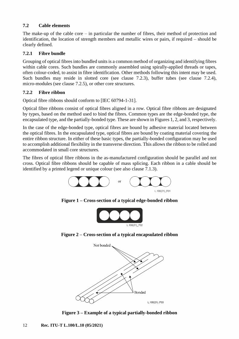
Optical fibre ribbons should conform to [IEC 60794-1-31].
Optical fibre ribbons consist of optical fibres aligned in a row. Optical fibre ribbons are designated
by types, based on the method used to bind the fibres. Common types are the edge-bonded type, the
encapsulated type, and the partially-bonded type. These are shown in Figures 1, 2, and 3, respectively.
In the case of the edge-bonded type, optical fibres are bound by adhesive material located between
the optical fibres. In the encapsulated type, optical fibres are bound by coating material covering the
entire ribbon structure. In either of these basic types, the partially-bonded configuration may be used
to accomplish additional flexibility in the transverse direction. This allows the ribbon to be rolled and
accommodated in small core structures.
The fibres of optical fibre ribbons in the as-manufactured configuration should be parallel and not
cross. Optical fibre ribbons should be capable of mass splicing. Each ribbon in a cable should be
identified by a printed legend or unique colour (see also clause 7.1.3).
Figure 1 – Cross-section of a typical edge-bonded ribbon
Figure 2 – Cross-section of a typical encapsulated ribbon
Figure 3 – Example of a typical partially-bonded ribbon

Rec. ITU-T L.100/L.10 (05/2021) 13
7.2.3 Slotted core
In order to avoid direct pressure from the outside of the cable on optical fibres, optical fibres and/or
fibre ribbons or other units may be located in slots inside a core structure. Usually, slots are provided
in a helical or reverse oscillating stranding (SZ) method configuration on a cylindrical rod. The slotted
core rod usually contains a strength member (metallic or non-metallic). The strength member should
adhere tightly to the slotted core in order to obtain temperature stability and avoid separation when a
pulling force is applied during installation. Water-blocking material may be contained within the
slots.
Figure 4 – Example of a slotted core structure cable
7.2.4 Tube (buffer tube)
A tube construction, commonly called a buffer tube or loose tube, is frequently used for protecting
and gathering optical fibres, fibre bundles, and/or fibre ribbons. The essential feature of the tube is
sufficient space inside the tube to isolate fibres, fibre bundles, or ribbons from external stress. The
tubes are commonly made of polymer materials. Cable designs incorporating loose tubes are the most
widely deployed, offering an optimized package for handling and robustness. The tubes may be
stranded around the other tubes or the central strength member. Such core structures minimize strain
and mid-span access may be easier if the SZ method is utilized. Central tube designs may also be
used. Water-blocking material may be contained in the tube, if required.
Figure 5 – Example of a loose tube cable construction

14 Rec. ITU-T L.100/L.10 (05/2021)
7.2.5 Micro-module
A micro-module is a thin-walled tubing unit (typically smaller and less robust than the buffer tube
described in clause 7.2.4). These flexible modules have bending radii similar to the unbundled fibre
or fibre bundles and are easy to strip without a tool for easy splice preparation and mid-span access.
They have no shape memory and may be used directly in an enclosure up to the splicing tray. Water-
blocking material may be contained within the micro-module, if required. Micro-modules may be
used within buffer tubes or slots. A typical micro-module is shown in Figure 6.
Figure 6 – Example of primary coated fibres protected by micro-module
7.2.6 Ruggedized fibre
When required for particular applications, further protection for a buffered fibre (see clause 7.1.2)
may be provided by surrounding one or more such fibres with an assembly of strength elements,
typically non-metallic, and an appropriate jacket material. Such assemblies are small in size and
typically reside in the cable core. Such ruggedization may be appropriate for break-out/fan-out cable
constructions.
Figure 7 – Examples of ruggedized fibre structure
7.2.7 Strength member
The duct and tunnel cable should be designed with sufficient strength members to meet installation
and service conditions so that the fibres themselves are not subjected to strain levels in excess of the
standard values (see clause A.3.1) or as agreed upon between customer and manufacturer.
Strength members mainly serve to limit tensile strain, but may also serve to limit compressive strain
as in temperature changes. The strength members may be located within the core or in the sheath
layers, or both. The strength member(s) may be either metallic or non-metallic.
When metallic strength members are used, care should be taken to avoid hydrogen generation effects
(see clause 6.3.8) and lightning hazards (see clause 6.3.9).

Rec. ITU-T L.100/L.10 (05/2021) 15
7.2.8 Water-blocking materials
Most duct and tunnel cables are water-blocked to protect the fibres from water ingress
(see clause 6.3.5 regarding air-core cables). Filling a cable – core and sheath interstices – with water-
blocking material or wrapping these areas with layers of water-swellable material, or both, are
common methods to protect the fibres from water ingress. A water-blocking element – filling
compound, water-swellable yarns or tapes, water-swelling powder, or combinations of materials –
may be used. Any materials used should not be harmful to personnel. The materials in the cable
should be compatible with one another, and, in particular, should not adversely affect the fibre. These
materials should not hinder splicing and/or connection operations (see clause A.4.7).
7.3 Sheath and jacket
The cable sheath is the assembly of elements that cover the cable core. This term may also be used to
mean the part of the assembly, which is the main covering of the cable, often termed the jacket. The
cable core should be covered with a sheath or sheaths suitable for the relevant environmental and
mechanical conditions associated with storage, installation, and operation. The sheath may be of a
composite construction and may include strength members. The sheath may include a moisture barrier
or inner jacket or armour, as needed, in addition to an outer jacket. The materials of the sheath should
be compatible with all of the elements of the cable sheath and core.
7.3.1 Moisture barrier
A moisture barrier may be one element of a cable sheath to inhibit moisture permeation
(see clause 6.3.4). If used, consideration should be given to the amount of hydrogen generated from
a metallic moisture barrier (see clause 6.3.8).
7.3.2 Inner sheath (jacket)
An inner sheath (jacket) layer may be used in the cable construction. The inner sheath may provide
additional protection under an armour, may be used to organize a cable as in break-out/fan-out cables,
or for other reasons.
7.3.3 Outer sheath (jacket)
The outer sheath (jacket) is the final covering of the cable. The selection of the outer sheath material
should be selected to resist the expected environmental hazards. The outer sheath material of duct
cables should optimize the friction forces between the cable sheath and duct. For tunnel cables, the
sheath construction – particularly the outer sheath material – should consider restrictions associated
with fire hazards.
NOTE – One of the most commonly used sheath materials is polyethylene. There may, however, be some
conditions where it is necessary to use other materials, for example, to limit fire hazards; to protect from
rodents and/or termites, etc.
7.4 Armour
Where protection from external damage (e.g., crush, impact, rodents) or additional tensile strength is
required armour should be provided.
Common armour materials are steel tapes of various constructions. Other metallic materials are
occasionally used. Heavy armour such as stranded wire servings is generally not used for duct or
tunnel cables. Hydrogen generation due to corrosion must be taken into consideration
(see clause 6.3.8).
It should be noted that the advantages of optical fibre cables, such as lightness and flexibility, will be
reduced when armour is provided.
Armour for metal-free cables may consist of aramid yarns, glass-fibre-reinforced strands, strapping
tape, etc.
16 Rec. ITU-T L.100/L.10 (05/2021)
7.5 Identification of cable
It is recommended that a visual identification of optical fibre cables be provided: this can be done by
visibly marking the outer sheath. Marking of cable length should be included in cable marking. For
identifying and length-marking cables, embossing, sintering, imprinting, hot foil, or ink-jet or laser
printing can be used by agreement between manufacturer and customer.
7.6 Cable sealing
It is recommended that an optical fibre cable should be provided with cable end-sealing and protection
during cable delivery and storage. If splicing components have been factory installed, they should be
adequately protected. Pulling devices can be fitted to the end of the cable, if required.
7.7 Considerations for duct installation
Installation of optical cables within ducts involves additional issues which should be considered. The
geometry of the duct run – access, bends, elevation changes, duct size – may inform the installation
method to be used. "Proving" of the duct – assessment that the duct is clear of debris and not crushed –
should be performed before any installation.
7.7.1 Installation method
In cable pulling, the pulling force should not exceed the cable tensile rating. The use of installation
lubrication can be of benefit.
NOTE – In addition to cable pulling, some cables in ducts are installed by blowing method, but pulling and
blowing have different cable requirements and conditions. See [ITU-T L.108] for cable requirements and
installation conditions applicable to the blowing installation.
The duct filling ratio–the comparison of the duct inner diameter to the cable outer diameter – should
be considered for determining the cable size (outer diameter). The presence of other cables already
in the duct should be considered.
7.7.2 Cable design considerations
The primary design consideration for pulling installation is the tensile rating of the optical cable.
The friction between the cable outer jacket and the duct inner surface should be carefully considered.
This is the main effect on installation tension. The duct filling ratio affects this consideration – both
in the materials and the cable size. The presence of other cables in the duct and their jacket
characteristics should be considered. The use of installation lubricants should be considered for the
installation method.

Rec. ITU-T L.100/L.10 (05/2021) 17
Annex A
Test methods
(This annex forms an integral part of this Recommendation.)
The tests are according to [IEC 60794-3-11] and the clauses below should be carried out for duct and
fibre cables. The attribute values stated herein should be used to assess conformance in the tests. It is
not intended that all tests should be carried out; see [IEC 60794-3-11] for guidance.
See [IEC 60794-3] regarding the frequency of testing; this should be agreed upon between the
manufacturer and customer.
The test methods, performance and test criteria are summarized in the following Tables A.1 to A.5.
Table A.1 – Optical fibre and cable elements test conditions
Characteristic Clause Test1 Value1, 2, 3 Note
Attenuation coefficient A.1.3 [IEC 60793-1-40] See Note 4
No Changes in
attenuation
A.1.3 – As specified in Note 5 as per [IEC 60794-1-1]
No Changes in fibre
strain
A.1.3 as applicable As specified in Note 5 as per [IEC 60794-1-1]
Test temperatures
Ambient A.1.4 as applicable Standard ambient and
expanded ambient,
see A.1.4
as per [IEC 60794-1-2]
Other temperatures A.1.5 as applicable within ± 5 °C of the
specified value
Note 1 – Tests are IEC unless otherwise specified. Letter/number tests are per the [IEC 60794-1-2] series unless
otherwise specified.
Note 2 – "as agreed" means per agreement between the manufacturer and the customer.
Note 3 – Reference to the L.100 invoking clause implies criteria not detailed in [IEC 60794-3-11] or the test method
and overly complex for this table.
Note 4 – Cabled fibre attenuation coefficient is specified in corresponding ITU-T G.65x series Recommendation.
Note 5 – No changes in attenuation/strain are related to test uncertainty as per [IEC 60794-1-1].

18 Rec. ITU-T L.100/L.10 (05/2021)
Table A.2 – Optical fibre and cable elements characteristics
Characteristic Clause Test1 Value1, 2, 3 Note
Fibre dimensions A.2.1.1 [IEC 60793-1-21] per [IEC 60793-2-50] per [IEC 60793-2-50]
Fibre coating
strippability
A.2.1.2 [IEC 60793-1-32] per [IEC 60794-3-11]
Material compatibility A.2.1.3 TBD TBD
Fibre buffers
Dimensions A.2.3.1 [IEC 60793-1-21]
or
[IEC 60811-203]
per [IEC 60794-3] or DS
Buffer strippability A.2.3.2 E5C of
[IEC 60794-1-21]
see A.2.3.2
Buffer tube
Dimensions A.2.4.1 [IEC 60811-202]
and
[IEC 60811-203]
per DS or as agreed
Tube kink A.2.4.2 G7 of
[IEC 60794-1-23]
per [IEC 60794-3-11]
Fibre ribbons [IEC 60794-1-31]
and
[IEC 60794-3-11]
Dimensions [IEC 60794-1-31] Table 1 of [IEC 60794-1-31]
Fibre separability A.2.5.2 [IEC 60794-1-31] [IEC 60794-1-31]
Strippability A.2.5.3 [IEC 60794-1-31]
and
[IEC 60793-1-32]
[IEC 60794-1-31]
Note 1 – Tests are IEC unless otherwise specified. Letter/number tests are per the [IEC 60794-1-2] series unless
otherwise specified.
Note 2 – "as agreed" means per agreement between the manufacturer and the customer.
Note 3 – Reference to the L.100 invoking clause implies criteria not detailed in [IEC 60794-3-11] or the test method
and overly complex for this table.
Rec. ITU-T L.100/L.10 (05/2021) 19
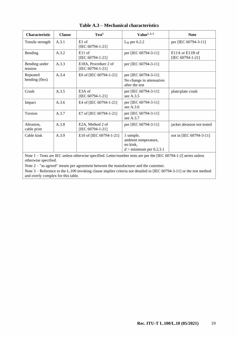
Table A.3 – Mechanical characteristics
Characteristic Clause Test1 Value1, 2, 3 Note
Tensile strength A.3.1 E1 of
[IEC 60794-1-21]
LM per 6.2.2 per [IEC 60794-3-11]
Bending A.3.2 E11 of
[IEC 60794-1-21]
per [IEC 60794-3-11] E11A or E11B of
[IEC 60794-1-21]
Bending under
tension
A.3.3 E18A, Procedure 2 of
[IEC 60794-1-21]
per [IEC 60794-3-11]
Repeated
bending (flex)
A.3.4 E6 of [IEC 60794-1-21] per [IEC 60794-3-11]
No change in attenuation
after the test
Crush A.3.5 E3A of
[IEC 60794-1-21]
per [IEC 60794-3-11]
see A.3.5
plate/plate crush
Impact A.3.6 E4 of [IEC 60794-1-21] per [IEC 60794-3-11]
see A.3.6
Torsion A.3.7 E7 of [IEC 60794-1-21] per [IEC 60794-3-11]
see A.3.7
Abrasion,
cable print
A.3.8 E2A, Method 2 of
[IEC 60794-1-21]
per [IEC 60794-3-11] jacket abrasion not tested
Cable kink A.3.9 E10 of [IEC 60794-1-21] 1 sample,
ambient temperature,
no kink,
d > minimum per 6.2.3.1
not in [IEC 60794-3-11]
Note 1 – Tests are IEC unless otherwise specified. Letter/number tests are per the [IEC 60794-1-2] series unless
otherwise specified.
Note 2 – "as agreed" means per agreement between the manufacturer and the customer.
Note 3 – Reference to the L.100 invoking clause implies criteria not detailed in [IEC 60794-3-11] or the test method
and overly complex for this table.
20 Rec. ITU-T L.100/L.10 (05/2021)
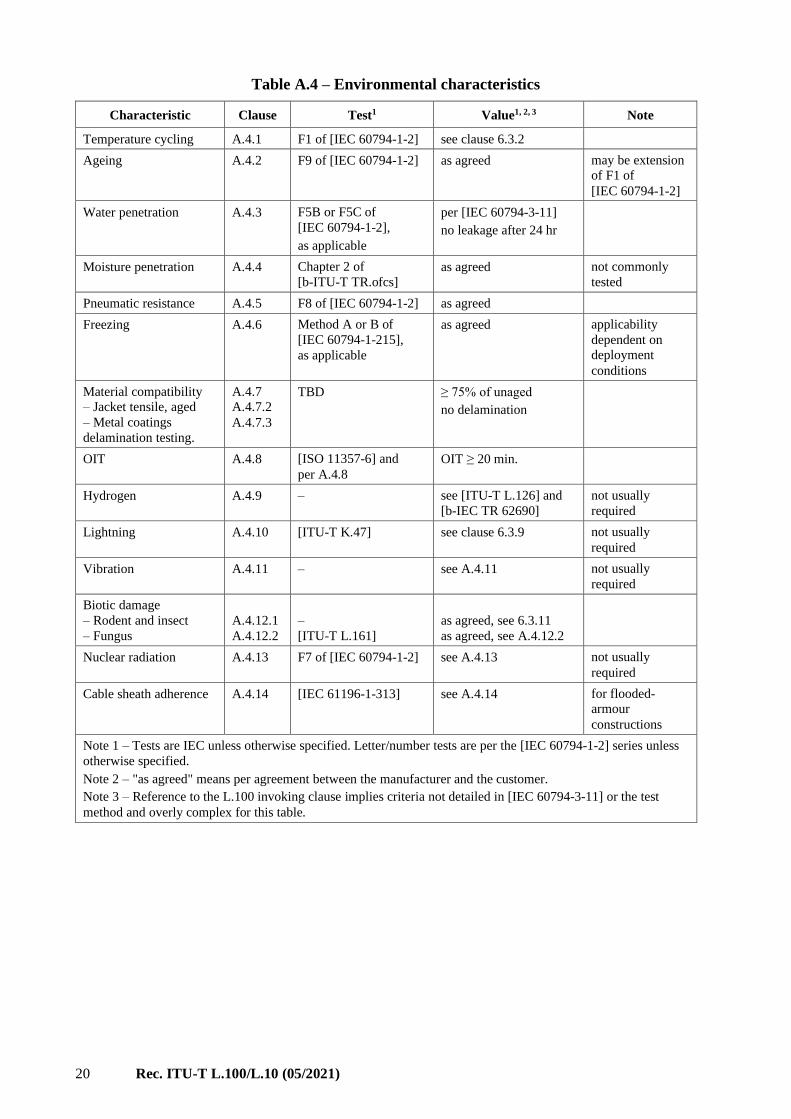
Table A.4 – Environmental characteristics
Characteristic Clause Test1 Value1, 2, 3 Note
Temperature cycling A.4.1 F1 of [IEC 60794-1-2] see clause 6.3.2
Ageing A.4.2 F9 of [IEC 60794-1-2] as agreed may be extension
of F1 of
[IEC 60794-1-2]
Water penetration A.4.3 F5B or F5C of
[IEC 60794-1-2],
as applicable
per [IEC 60794-3-11]
no leakage after 24 hr
Moisture penetration A.4.4 Chapter 2 of
[b-ITU-T TR.ofcs]
as agreed not commonly
tested
Pneumatic resistance A.4.5 F8 of [IEC 60794-1-2] as agreed
Freezing A.4.6 Method A or B of
[IEC 60794-1-215],
as applicable
as agreed applicability
dependent on
deployment
conditions
Material compatibility
– Jacket tensile, aged
– Metal coatings
delamination testing.
A.4.7
A.4.7.2
A.4.7.3
TBD ≥ 75% of unaged
no delamination
OIT A.4.8 [ISO 11357-6] and
per A.4.8
OIT ≥ 20 min.
Hydrogen A.4.9 – see [ITU-T L.126] and
[b-IEC TR 62690]
not usually
required
Lightning A.4.10 [ITU-T K.47] see clause 6.3.9 not usually
required
Vibration A.4.11 – see A.4.11 not usually
required
Biotic damage
– Rodent and insect
– Fungus
A.4.12.1
A.4.12.2
–
[ITU-T L.161]
as agreed, see 6.3.11
as agreed, see A.4.12.2
Nuclear radiation A.4.13 F7 of [IEC 60794-1-2] see A.4.13 not usually
required
Cable sheath adherence A.4.14 [IEC 61196-1-313] see A.4.14 for flooded-
armour
constructions
Note 1 – Tests are IEC unless otherwise specified. Letter/number tests are per the [IEC 60794-1-2] series unless
otherwise specified.
Note 2 – "as agreed" means per agreement between the manufacturer and the customer.
Note 3 – Reference to the L.100 invoking clause implies criteria not detailed in [IEC 60794-3-11] or the test
method and overly complex for this table.

Rec. ITU-T L.100/L.10 (05/2021) 21
Table A.5 – Cable construction
Characteristic Clause Test1 Value1, 2, 3 Note
Dimensions A.2.6.1 [IEC 60811-202] and
[IEC 60811-203]
as agreed
Cable OD A.2.6.2 [IEC 60811-203] stated by manufacturer,
per [IEC 60794-3-11]
Sheath thickness A.2.6.3 [IEC 60811-203] per [IEC 60794-3-11] or
as agreed
Moisture barrier
adhesion
A.2.6.4 [IEC 60708] per [IEC 60794-3-11]
Note 1 – Tests are IEC unless otherwise specified. Letter/number tests are per the [IEC 60794-1-2] series unless
otherwise specified.
Note 2 – "as agreed" means per agreement between the manufacturer and the customer.
Note 3 – Reference to the L.100 invoking clause implies criteria not detailed in [IEC 60794-3-11] or the test method
and overly complex for this table.
A.1 Standard test criteria
A.1.1 Tensile strength of duct and tunnel cables
Testing for criteria involving cable tensile strength should be carried out using the tensile rating of
clause 6.2.2.
A.1.2 Temperature test values for duct and tunnel cables
Testing for criteria involving defined temperature extremes should be considered to be carried out
using the temperature ranges. Some tests may specify specific test temperatures different from the
standard temperature ranges.
A.1.3 Attenuation coefficient and changes (no change and allowable change) in
attenuation/strain in cable testing
Herein, the term "attenuation" may be understood to mean "attenuation coefficient," depending on
the attribute.
Unless otherwise specified, testing for attenuation requirements should be carried out at 1550 nm for
all single-mode fibres, subject to the ITU-T Recommendations on fibre in Table 1.
Unless otherwise specified, changes in attenuation should be calculated with respect to the attenuation
values before the start of the test. In most cases, this measurement should be at ambient temperature
(see clause A.1.4).
Unless otherwise specified, for tests with attenuation requirements the attenuation increase or
decrease at the completion of the test should be no change.
Unless otherwise specified, the defined values for "no change" should be per [IEC 60794-1-1], which
are:
• single-mode, no change in attenuation ≤ 0.05 dB or ≤ 0.05 dB/km at 1550 nm
• all types, no change in fibre strain ≤ 0.05%
A.1.4 Ambient temperatures for cable testing
The ambient temperatures for cable testing should be according to [IEC 60794-1-2] as shown in
Table A.6. All testing should use the expanded ambient criteria unless disallowed by the test
procedure or as agreed.

22 Rec. ITU-T L.100/L.10 (05/2021)
Table A.6 – Ambient temperature, relative humidity, and atmospheric pressure
Condition Standard Ambient Expanded Ambient
Temperature 23°C ± 5°C 25°C ± 15°C
Relative Humidity 20% to 70% 5% to 95%
Atmospheric Pressure Site Ambient Site Ambient
A.1.5 Temperature precision at extremes
The temperature value at test temperatures other than ambient should be within ± 5 ºC of the specified
values (see clause 6.3.2 and clause A.1.4).
A.2 Test methods for cable elements
A.2.1 Tests applicable to optical fibres
In this clause, optical fibre test methods for assessing fibres and test methods related to splicing and
other joining methods are described. Mechanical and optical characteristics test methods for optical
fibres are described in [ITU-T G.650.1], [ITU-T G.650.2] and [IEC 60793-1-xx] fibre test methods
series.
A.2.1.1 Dimensions
For measuring the primary coating diameter, method [IEC 60793-1-21] should be used.
The measured dimensions for cabled fibre should be per [IEC 60793-2-50] or as agreed.
A.2.1.2 Coating strippability
For measuring the strippability of primary or secondary fibre coatings, method [IEC 60793-1-32]
should be used. The strip force should be according to [IEC 60794-3-11].
A.2.1.3 Compatibility with filling materials
When fibres come into contact with a filling material used for waterproofing, stability of the fibre
coating and the filling material should be examined by tests after accelerated ageing.
Compatibility of optical fibres and buffers with a filling material should be tested per
[IEC 60794-3-11].
Dimensional stability and coating transmissivity should be examined by the test method as agreed.
A.2.2 Tests applicable to fibre units
A.2.2.1 Colour coding of fibre
There is no international standard on fibre colour coding. The fibre colouring should comply with the
detail specification, which may reflect in National or Regional norms. See [b-IEC TR 63194] for
guidance.
Colours used should comply with [IEC 60304].
A.2.2.2 Fibre and unit identification
Fibre and unit identification should also comply with the detail specification, which may reflect in
National or Regional norms. See [b-IEC TR 63194] for guidance.
Colours used should comply with [IEC 60304].

Rec. ITU-T L.100/L.10 (05/2021) 23
A.2.3 Tests applicable to buffered optical fibres
A.2.3.1 Dimensions
The outer diameter of all types of fibre secondary coatings (buffers) should comply with
[IEC 60794-3] or with the detail specification. The diameter tolerance should comply with
[IEC 60794-3].
Measurements should be performed using [IEC 60793-1-21] or [IEC 60811-203].
A.2.3.2 Buffer strippability
Buffers should be strippable in a manner consistent with their intended method of connectorization
or splicing.
Buffers should be cable of being stripped using the parameters as shown in Table A.7. Stripping
methods and measurements should be performed according to [IEC 60794-1-21] method E5C.
Table A.7 – Strip lengths and forces for buffer strippability test
Buffer type Material stripped Strip Length Strip force
Tight Remove buffer and primary
coating as a unit
15 mm ± 1.5 mm 1.3 N to 13 N
Semi-tight Remove buffer, primary
coating intact
15 mm ± 1.5 mm < 13 N
Easily-removable semi-tight Remove buffer, primary
coating intact
150 mm as agreed
A.2.4 Tests applicable to buffer tubes
A.2.4.1 Dimensions
Buffer tube dimensions should be according to the detail specification or as agreed between
manufacturer and customer.
For measuring buffer tubes the methods of [IEC 60811-202] and [IEC 60811-203] should be used.
A.2.4.2 Tube kink
Tube kinking characteristics and testing should be according to [IEC 60794-3-11].
For measuring kink characteristics of tubes, [IEC 60794-1-23] method G7 should be used.
A.2.5 Tests applicable to ribbons
Testing of fibre ribbons should be according to [IEC 60794-1-31] and [IEC 60794-3-11].
A.2.5.1 Dimensions
Fibre ribbon dimensions should be according to [IEC 60794-1-31], Table 1. Ribbon dimensions
should be measured according to [IEC 60794-1-31].
A.2.5.2 Separability of individual fibres from a ribbon
Separability of individual fibres from a ribbon should be according to [IEC 60794-1-31].
A.2.5.3 Strippability
Strippability of ribbons, as a whole or in units, should be according to [IEC 60794-1-31] and as
follows.

24 Rec. ITU-T L.100/L.10 (05/2021)
At least 25 mm of the matrix and the fibres' protective coatings should be removable with
commercially available stripping tools from aged and unaged ribbons. There should be no fibre
breakage. Any remaining coating residue should be readily removable using isopropyl alcohol wipes.
Ribbon ageing is under study. Stripping force should be measured using [IEC 60793-1-32] as
applicable to the multiple fibres in a ribbon.
A.2.6 Cable element measurements
A.2.6.1 Dimensions
Dimensions for other tubes, slotted core, micro-modules, other ruggedized fibres, strength members,
jackets, or other cable elements should be as agreed between the manufacturer and customer.
Measurement of these cable elements should use methods [IEC 60811-202] and [IEC 60811-203], as
applicable.
A.2.6.2 Cable diameter
The cable outer diameter should not exceed the maximum stated by the manufacturer in accordance
with [IEC 60794-3-11].
The measurement should be in accordance with [IEC 60811-203].
A.2.6.3 Sheath thickness
The sheath thickness of duct and tunnel cable should be in accordance with [IEC 60794-3-11], or as
alternately agreed between the manufacturer and customer.
Measurement should be in accordance with [IEC 60811-203].
A.2.6.4 Moisture barrier adhesion
If a moisture barrier tape is used, it should be in accordance with [IEC 60794-3-11].
The adhesion of the tape to the sheath should be tested in accordance with [IEC 60708].
A.3 Test methods for mechanical characteristics of the cable
This clause recommends appropriate tests and test methods for verifying the mechanical
characteristics of duct and tunnel cables.
Performance and acceptance criteria and testing should comply with [IEC 60794-3] and
[IEC 60794-3-11] and the clauses below. Testing should be done according to [IEC 60794-1-21] and
its subordinate specifications.
A.3.1 Tensile strength
This test method applies to duct and tunnel cables installed under all environmental conditions.
Measurements are made to examine the behaviour of the fibre attenuation and fibre strain as a function
of the load on a cable during installation and during its lifetime.
The cable should perform in accordance with [IEC 60794-3-11], using the criteria below.
The rated tensile load, also termed short-term load, LS, should be the nominal value consistent with
the tensile load ratings of clause 6.2.2.1. The residual load, or long-term load, LL, should be 30% of
LS, as per clause 6.2.2.1.
A tensile rating in excess of LS may be declared by the manufacturer. But, testing should be carried
out at the rated tensile load.

Rec. ITU-T L.100/L.10 (05/2021) 25
The maximum changes in attenuation should be:
– Attenuation changes should not be specified at LS, as this is a sort term load event.
– There should be no change in attenuation at LL and after removal of the load; see clause A.1.3.
The fibre strain under load should be:
– ≤ 60% of the fibre proof strain under load LS;
– ≤ 20% of the fibre proof strain under load LL, for fibres proof tested at 1% strain; or
≤ 17% of the fibre proof strain under load LL, for fibres proof tested at greater than 1% up to
2% strain.
The test should be carried out in accordance with [IEC 60794-1-21] method E1.
There should be no damage to the sheath or cable elements under visual examination.
A.3.2 Bending
This test method applies to duct and tunnel cables installed under all environmental conditions.
The purpose of this test is to determine the ability of optical fibre cables to withstand coiling or
bending around a pulley, simulated by a test mandrel.
The cable should perform in accordance with [IEC 60794-3-11].
This test should be carried out in accordance with [IEC 60794-1-21] method E11. The bending
diameter should be according to clause 6.2.3.1. The mandrel or sheave diameter should be ± 10% of
the specified value.
A.3.3 Bending under tension
This test method applies to duct and tunnel cables installed under all environmental conditions.
The purpose of this test is to determine the ability of an optical fibre cable to withstand bending
around rollers or bows during installation, when a specified load is applied.
This test should be carried out in accordance with [IEC 60794-1-21] method E18A, procedure 2:
– tension: cable rated tensile load, LS;
– length of cable tested in the bend:
distance required for the circuit between the roller/sheave exits,
plus 10 m;
– length of cable/end preparation:
no end preparation required for cable length of 100 m or greater
cable elements fixed together at either end for cable lengths less
than 100 m;
– radius of rollers/sheaves, R:
1/2 (20 d or 40 d, per clause 6.2.3.1), ± 10%;
– bending angle, θ: between 90º and 135º;
– number of cycles: 3.
There should be no change in attenuation after the test.
There should be no visible cracking of the sheath components when removed successively and
examined.
A.3.4 Repeated bending
This test method applies to duct and tunnel cables installed under all environmental conditions.
The purpose of this test is to evaluate the ability of optical fibre cables to undergo repeated bending
associated with normal handling and service.

26 Rec. ITU-T L.100/L.10 (05/2021)
The cable should perform in accordance with [IEC 60794-3-11], and tested in accordance with
[IEC 60794-1-21] method E6 with the following criteria:
– mandrel radius, r: 1/2 20 d (per clause 6.2.3.1), with a minimum value of 150 mm, ± 10%.
The maximum increase in attenuation during the test should be:
– 0.15 dB at 1550 nm for single-mode fibres.
There should be no change in attenuation after the test.
There should be no visible cracking of any armour or shield greater than 5 mm in length. Inspection
should be performed using 5 magnification. There should be no visible damage to the other cable
elements.
A.3.5 Crush
This test method applies to duct and tunnel cables installed under all environmental conditions.
The appropriate test method for most terrestrial cables is the plate-plate crush method.
The cable should perform in accordance with [IEC 60794-3-11], and tested in accordance with
[IEC 60794-1-21] method E3A using the following criteria:
• Short term test segment – load applied for 1 min;
• Long term test segment – load applied for 10 min;
• Plate/plate loads, per [IEC 60794-3-11] as shown in Table A.8;
• Measure attenuation at the end of the long term loading, before releasing the load.
There should be no change in attenuation at the end of the long term loading.
Table A.8 – Plate/plate loads for crush test
Short term Long term
Unarmoured cable 1.5 kN 0.75 kN
Armoured cable 2.2 kN 1.1 kN
A.3.6 Impact
This test method applies to duct and tunnel cables installed under all environmental conditions.
The purpose of this test is to evaluate the ability of optical fibre cables to survive impacts associated
with normal installation and handling.
The cable should perform in accordance with [IEC 60794-3-11], and tested in accordance with
[IEC 60794-1-21] method E4 using the following criteria:
• Use the standard, flat hammer (300 mm minimum face radius);
• Strike the cable 1 time in each of 3 different places, spaced not less than 150 mm ± 15 mm
apart;
• Use an impact energy of:
10 J for non-armoured cable;
20 J for armoured cable.
A.3.7 Torsion
This test method applies to duct and tunnel cables installed under all environmental conditions.
The purpose of this test is to evaluate the ability of optical fibre cables to accommodate torsion
associated with normal installation and handling.

Rec. ITU-T L.100/L.10 (05/2021) 27
The cable should perform in accordance with [IEC 60794-3-11], and tested in accordance with
[IEC 60794-1-21] method E7 using the following criteria:
• Length under test: 2 m;
• Sample rotation: 180º in each direction;
• 5 cycles.
NOTE – Different sample lengths and rotations equivalent to 90º/m may be used.
After the test, there should be no change in attenuation.
A.3.8 Abrasion of cable printing
This test method applies to duct and tunnel cables installed under all environmental conditions.
The purpose of this test is to evaluate the permanence of cable printing.
The cable should perform in accordance with [IEC 60794-3-11], and tested in accordance with
[IEC 60794-1-21] method E2A, Method 2. This method tests the print using the felt pad method.
After the test, the cable printing should still be legible.
A.3.9 Kink
This test method applies to duct and tunnel cables installed under all environmental conditions.
The purpose of this test is to evaluate the ability of optical fibre cables to undergo normal handling
without kinking.
This test should be carried out in accordance with [IEC 60794-1-21] method E10. The test criteria
should be:
• Test 1 sample;
• Perform the test at ambient temperature.
The cable should not kink at a loop diameter greater than the cable minimum bend diameter
(see clause 6.2.3.1). There should be no attenuation requirement.
A.4 Test methods for environmental characteristics
This clause recommends the appropriate tests and test methods for verifying the environmental
characteristics of duct and tunnel cables.
Performance and acceptance criteria and testing should comply with [IEC 60794-3] and
[IEC 60794-3-11] and the clauses below. Testing should be done according to [IEC 60794-1-2] and
its subordinate specifications.
Appropriate temperature ranges for duct and tunnel cables are shown in clause 6.3.2, Table 1. Unless
other temperature ranges are specified for particular applications, the values in Table 1 should be
used.
A.4.1 Temperature cycling
This test method applies to duct and tunnel cables installed under all environmental conditions.
Testing is carried out by temperature cycling to determine the stability of the attenuation of a cable
due to temperature changes, which may occur during operation.
The cable should perform in accordance with [IEC 60794-3-11], and tested in accordance with
[IEC 60794-1-2] method F1 at the operational temperature per clause 6.3.2, Table 1. These
temperatures are TA2 and TB2 of method F1. Other temperature values or intermediate values in
method F1 should be as agreed between manufacturer and customer.

28 Rec. ITU-T L.100/L.10 (05/2021)
Attenuation changes at all temperatures should be calculated as deviations from the value at the initial
measurement at ambient temperature.
There should be no change in attenuation at ambient temperature after the test.
A.4.2 Ageing
This test method applies to duct and tunnel cables installed under all environmental conditions.
The purpose of this test is to evaluate the reaction of cable components under simulated ageing by
applying a high temperature to accelerate ageing.
This test should be carried out in accordance with [IEC 60794-1-2] method F9, usually as an extension
of the temperature cycling test of clause A.4.1.
Attenuation changes at the end of the ageing period should be calculated as deviations from the value
at initial ambient for this test. If this test is carried out as an extension of the temperature cycling test,
the initial ambient point for ageing is at the end of the temperature cycling test. Unless otherwise
specified, the attenuation change at the end of the test should be:
• 0.25 dB/km, maximum, and 0.10 dB/km, average, at 1550 nm for single-mode fibres.
A.4.3 Longitudinal water penetration
This test method applies to water-blocked outdoor cables installed under all environmental
conditions.
The intention is to check that all the interstices of a cable are sufficiently filled with a compound or
water blocking material to prevent water penetration within the cable.
The cable should perform in accordance with [IEC 60794-3-11]. Testing should be carried out in
accordance with [IEC 60794-1-2] method F5B or [IEC 60794-1-2] method F5C, as appropriate to the
design.
There should be no leakage at the end of the cable after 24 hours in the test or retest, as per
[IEC 60794-1-2] method F5.
A.4.4 Moisture permeation
This test method applies to duct and tunnel cables installed under all environmental conditions.
This test applies to cables supplied with a longitudinal overlapped metallic foil. The moisture
permeation can be tested according to the test method as described in Chapter 2 of [b-ITU-T TR.ofcs].
Requirements should be agreed between the manufacturer and customer.
A.4.5 Pneumatic resistance
If a gas pressurization system is used to protect non-water-blocked duct or tunnel optical fibre cables,
this test may be appropriate.
The purpose of this test is to assure that an adequate amount of gas flow will pass through the cable.
This test should be carried out in accordance with [IEC 60794-1-2] method F8. The specimen length
and maximum pneumatic resistance should be according to a detail specification agreed between the
manufacturer and customer.
If the intent is to provide gas blocking in a cable, the referenced test method should be used with
minimum pneumatic resistance criteria as agreed between the manufacturer and customer.
A.4.6 Freezing
Freezing testing comprises two related test methods applicable to optical fibre cables installed under
environmental conditions in which freezing of the ground surrounding the cable or duct containing
the cable may occur. The cases are a cable within a duct buried directly in the ground or similarly

Rec. ITU-T L.100/L.10 (05/2021) 29
surrounded by a medium which can freeze and a cable in a buried duct which is subject to water
intrusion. The latter is of most usefulness for duct and tunnel cables (see clause 6.3.6).
A.4.6.1 Freezing in an unconfined space
This test is not often used for duct and tunnel cable. The purpose of the external freezing test is to
simulate freezing of the medium surrounding a buried cable, as in wet earth or water. It is not intended
to simulate freezing of a cable in a duct or pipe (see clause 6.3.6 for the applicability of this test).
It may be useful for evaluating duct and tunnel cables not normally intended for outdoor installation.
This test should be carried out in accordance with method [IEC 60794-1-215] method F15A.
Unless otherwise specified, the allowable change in attenuation when the cable is frozen should be:
• ≤ 0.15 dB/km at 1550 nm.
Unless otherwise specified, there should be no change in attenuation at ambient temperature after the
test.
A.4.6.2 Freezing of cable in a duct
The purpose of the external freezing test for cable within a duct is to simulate freezing of the medium
surrounding a buried duct or freezing temperatures affecting an aerial duct containing a cable or
cables into which water might collect and surround the cable (see clause 6.3.6 for the applicability of
this test). In applications where water intrusion into a rigid duct is considered, it is common to install
cables along with pressure absorbing elements within the duct. The intent of this test is to evaluate
the assembly of the cable, and pressure absorber elements, if any, and the duct when frozen.
This test should be carried out in accordance with method [IEC 60794-1-215] method F15B.
Unless otherwise specified, the allowable change in attenuation when the cable is frozen should be:
• ≤ 0.15 dB/km at 1550 nm.
Unless otherwise specified, there should be no change in attenuation at ambient temperature after the
test.
A.4.7 Material compatibility
This test method applies to duct and tunnel cables installed under all environmental conditions. This
test may apply to all duct and tunnel cables, but particularly applies to cables using polymeric gels or
flooding compounds. Cables not utilizing the above should be tested as agreed between manufacturer
and user, following the intent of this clause.
This test method is intended to ensure compatibility of the cable materials (e.g., fibres, plastics, water
blocking materials, and metals) over the cable's lifetime. The procedure simulates lifetime exposure
by ageing a whole-cable specimen or selected elements of a cable at an elevated temperature over a
period of time. Fibre and buffered fibre compatibility testing is addressed in clauses A.2.1 and A.2.3,
which may be done in conjunction with this test.
A.4.7.1 Procedure for ageing
Ageing of completed cable specimens is under study. Control specimens for "before ageing"
comparison or testing should be maintained.
After ageing, the components should be removed from the cable or element assemblies and tested as
follows.
A.4.7.2 Jacket tensile strength and elongation testing – after ageing
Jacket material tensile and elongation should be tested in accordance with [IEC 60811-501]. The aged
jacket shall retain a minimum of 75% of its unaged tensile strength and elongation values.

30 Rec. ITU-T L.100/L.10 (05/2021)
A.4.7.3 Metal coatings delamination testing – after ageing
Plastic coatings on metal tapes should show no visual evidence of delamination.
A.4.8 Oxidative induction time, OIT – for polyolefin filling and jacket materials
Filling compounds and polyolefin-base jacket materials in all duct and tunnel cables installed in all
environmental conditions should be tested to assess the level of stabilization of the material. The
oxidative induction time, OIT, test performs such an assessment using differential scanning
calorimetry (DSC) techniques.
The mass of the specimen should be per [ISO 11357-6]. A filling compound sample may be either
from incoming material or from a finished cable. Jacket material should be from a finished cable or
specifically manufactured simulated cable jackets.
The specimen should be tested per [ISO 11357-6] with the following modifications and clarifications:
• For filling compound – the test temperature should be 190ºC ± 0.5ºC;
• For polyolefin jacket material – the test temperature should be 199ºC ± 1ºC;
• The rate of heating of the test sample should be 10ºC/min;
• An aluminium pan should be used in place of the copper crucible (pan);
• Screens should not be used;
• The torque rheometer is not required.
The minimum OIT should be 20 minutes for filling compound or jacket material.
A.4.9 Hydrogen
This test rarely applies to duct and tunnel cables. This test method applies to optical fibre cable
installed in a submarine environment or in higher atmospheric pressure applications. In the unusual
case where a duct or tunnel cable resides in a hermetically sealed duct, hydrogen testing may be
considered.
In the case of a metal-free cable or one employing a moisture barrier sheath with a selection of cable
components which are low in the generation of hydrogen, either by themselves or in combination
with others (for example, water), the build-up of hydrogen gas within the cable core will not lead to
a significant increase in optical loss.
For other cable constructions, [ITU-T L.126] and [b-IEC TR 62690] should be consulted.
A.4.10 Lightning
While of secondary importance to duct and tunnel cables, lightning testing should be considered
(see clause 6.3.9).
When a metallic material is used as a cable element, the lightning protection of a cable may undergo
a test described in [ITU-T K.47], subject to agreement between the customer and manufacturer.
A.4.11 Vibration
Vibration testing should be as agreed between the manufacturer and customer (see clause 6.3.9).
Vibration testing per [IEC 60794-1-21], method E19, Aeolian vibration, or method E26, Galloping,
is generally not applicable to duct and tunnel cables.
A.4.12 Biotic damage
A.4.12.1 Rodent and insect damage
Testing for resistance of duct and tunnel cable to damage from rodent or insect attach should be as
agreed between the manufacturer and customer (see clause 6.3.11).

Rec. ITU-T L.100/L.10 (05/2021) 31
A.4.12.2 Fungus resistance of jackets
Fungus evaluation is applicable to cables installed in all environmental conditions. Polyethylene
jacket materials commonly used in duct and tunnel cables are inherently non-nutritive to fungus.
Other jacket materials, including those which may be applied for fire rated cables or as outer jackets,
may require evaluation for fungus resistance.
The test methods and requirements should be as agreed between manufacturer and user.
[ITU-T L.161] may be consulted for guidance. Test methods for assessing fungus resistance are under
development in IEC.
A.4.13 Nuclear radiation
This test method assesses the suitability of optical fibre cables to be exposed to nuclear radiation.
This test should be carried out in accordance with [IEC 60794-1-2] method F7.
A.4.14 Cable sheath adherence
This test applies to duct and tunnel cables installed under all environmental conditions. A range of
installation techniques can apply a frictional force to the outer jacket, which may cause the jacket to
slip with respect to the underlying cable – either in tension or compression.
The test is applicable to cables in which the jacket is not adhesively bonded to the underlying cable
structure. Generally, these are dielectric or metallic cables without strength members in the jacket or
armoured cables, all with flooding compound applied over the inner structure or the shield or armour.
Cables which are not water blocked are also subject to this test. Cables using a bonded armour
construction are not tested due to the inherently high longitudinal bond strength of such constructions.
The test measures the resistance of the cable sheath components (shield or armour and the overlaying
jacket) to separation, one from another, by measuring the force required to pull the cable core and
metallic covering out of the jacket.
Cables should be tested according to [IEC 61196-1-313] or following the intent, as modified below.
The test should be at expanded ambient temperature per clause A.1.4.
A.4.14.1 Test procedure
In using the terminology of the referenced test method, the "conductor" or "outer conductor" should
be the core assembly without the jacket. The "dielectric" or "sheath" should be the cable jacket.
The tested specimen should be of sufficient length to provide the test length of 300 mm ± 15 mm, per
Figure A.1, and the prepared length of core and jacket. The prepared lengths of core and split jacket
should be a length convenient for testing, generally about 100 mm each. The test may also be
performed using the test plate of the referenced test rather than preparing the jacket.
The test should be performed per [IEC 61196-1-313], as shown in Figure A.1, for illustration.

32 Rec. ITU-T L.100/L.10 (05/2021)
Figure A.1 – Sheath adherence test apparatus and sample
A.4.14.2 Requirements
The sheath adherence should have a value greater than 14 N/mm of the circumference of the inner
surface of the jacket. That circumference is most conveniently measured as the outer circumference
of the armour, shield, or underlying cable structure.

Rec. ITU-T L.100/L.10 (05/2021) 33
Bibliography
[b-ITU-T TR.ofcs] ITU-T Technical Report TR-OFCS (2015), Optical fibres, Cables and
Systems. https://www.itu.int/pub/T-TUT-HOME-2015-OFCS
[b-IEC 60793-2] IEC 60793-2 (2019), Optical fibres – Part 2: Product specifications –
General.
[b-IEC TR 62222] IEC TR 62222 (2021), Fire performance of communication cables
installed in buildings.
[b-IEC TR 62690] IEC TR 62690 (2014), Hydrogen effects in optical fibre cables –
Guidelines.
[b-IEC TR 63194] IEC TR 63194 (2019), Guidance on colour coding of optical fibre cables.
[b-IEC TR 62691] IEC TR 62691 (2016), Optical fibre cables – Guidelines to the
installation of optical fibre cables.
[b-ITU-T G Suppl.40] ITU-T G-series Recommendations – Supplement 40 (2018), Optical fibre
and cable Recommendation and standards guideline.
[b-ITU-T G Suppl.59] ITU-T G-series Recommendations – Supplement 59 (2018), Guidance on
optical fibre and cable reliability.


ITU-T L-SERIES RECOMMENDATIONS
ENVIRONMENT AND ICTS, CLIMATE CHANGE, E-WASTE, ENERGY EFFICIENCY; CONSTRUCTION,
INSTALLATION AND PROTECTION OF CABLES AND OTHER ELEMENTS OF OUTSIDE PLANT
OPTICAL FIBRE CABLES
Cable structure and characteristics L.100–L.124
Cable evaluation L.125–L.149
Guidance and installation technique L.150–L.199
OPTICAL INFRASTRUCTURES
Infrastructure including node elements (except cables) L.200–L.249
General aspects and network design L.250–L.299
MAINTENANCE AND OPERATION
Optical fibre cable maintenance L.300–L.329
Infrastructure maintenance L.330–L.349
Operation support and infrastructure management L.350–L.379
Disaster management L.380–L.399
PASSIVE OPTICAL DEVICES L.400–L.429
MARINIZED TERRESTRIAL CABLES L.430–L.449
E-WASTE AND CIRCULAR ECONOMY L.1000–L.1199
POWER FEEDING AND ENERGY STORAGE L.1200–L.1299
ENERGY EFFICIENCY, SMART ENERGY AND GREEN DATA CENTRES L.1300–L.1399
ASSESSMENT METHODOLOGIES OF ICTS AND CO2 TRAJECTORIES L.1400–L.1499
ADAPTATION TO CLIMATE CHANGE L.1500–L.1599
LOW COST SUSTAINABLE INFRASTRUCTURE L.1700–L.1799
For further details, please refer to the list of ITU-T Recommendations.
Printed in Switzerland Geneva, 2021
SERIES OF ITU-T RECOMMENDATIONS
Series A Organization of the work of ITU-T
Series D Tariff and accounting principles and international telecommunication/ICT economic and
policy issues
Series E Overall network operation, telephone service, service operation and human factors
Series F Non-telephone telecommunication services
Series G Transmission systems and media, digital systems and networks
Series H Audiovisual and multimedia systems
Series I Integrated services digital network
Series J Cable networks and transmission of television, sound programme and other multimedia
signals
Series K Protection against interference
Series L Environment and ICTs, climate change, e-waste, energy efficiency; construction,
installation and protection of cables and other elements of outside plant
Series M Telecommunication management, including TMN and network maintenance
Series N Maintenance: international sound programme and television transmission circuits
Series O Specifications of measuring equipment
Series P Telephone transmission quality, telephone installations, local line networks
Series Q Switching and signalling, and associated measurements and tests
Series R Telegraph transmission
Series S Telegraph services terminal equipment
Series T Terminals for telematic services
Series U Telegraph switching
Series V Data communication over the telephone network
Series X Data networks, open system communications and security
Series Y Global information infrastructure, Internet protocol aspects, next-generation networks,
Internet of Things and smart cities
Series Z Languages and general software aspects for telecommunication systems