rebranded site planning guide 027264f
TRANSCRIPT

Cyberknife® System and Cyberknife® VSITM System
Site Planning Guide


Cyberknife® System and Cyberknife® VSITM System
Site Planning Guide

Cyberknife® System Cyberknife® VSITM System
Site Planning Guide
Copyright © 2001-2012 by Accuray, Incorporated
All Rights Reserved
Part number: 027264
Revision: F
Date:
EC Declaration of Conformity
Application of Council Directive: 93/42/EEC
Manufacturer’s name: Accuray, Incorporated
Manufacturer’s address: 1310 Chesapeake Terrace, Sunnyvale, CA 94089
Type of equipment: Radiotherapy equipment
Note: Any modification of the named device without written authorization by Accuray, Inc. will invalidate this declaration.
Copyright Information
This document, the software (© 2001-2012) and products to which this document refers, and any other related materials are the copyrighted and proprietary information of Accuray Incorporated and may not be used or distributed without written authorization of Accuray Incorporated. No part of this document may be photocopied, reproduced, or translated into another language without written permission from Accuray Incorporated.
Accuray Incorporated reserves the right to revise this publication and to make changes in content from time to time without obligation on the part of Accuray Incorporated to provide notification of such revision or change.
Accuray Incorporated provides this document without warranty of any kind, either implied or expressed, including, but
not limited to, the implied warranties of merchantability and fitness for a particular purpose. Accuray Incorporated and
its principals, officers, representatives, subsidiaries, employees, agents, heirs and assigns assume no responsibility
or liability, either express or implied, for injury, death, or losses to consumers, users or service personnel resulting
from improper handling of the Accuray® products by unauthorized, untrained or otherwise unqualified personnel.
Accuray Incorporated expressly denies any responsibility or liability for abuse, neglect, misuse or tampering with
Accuray system components by persons not authorized, trained or otherwise associated with Accuray Incorporated.
CyberKnife® is a trademark of Accuray, Inc. All other products or services mentioned in this manual are identified by
the trademark or service marks of their respective companies or organizations. Accuray Incorporated disclaims any
responsibility for specifying which marks are owned by which companies or organizations.

P/N 027264, Rev F v
TABLE OF CONTENTS Introduction .................................................................................................................... 1
Scope ....................................................................................................................................................... 1 Overview ................................................................................................................................................... 1 Regulatory Needs ..................................................................................................................................... 1 Accuray Contact Information .................................................................................................................... 2 Roles and Responsibilities ....................................................................................................................... 3
1. System Components, Descriptions and Site Planning Considerations ............... 7 1.1 Treatment Room (also known as the Vault or Bunker) ....................................................................... 7 1.2 Control Room ................................................................................................................................... 13 1.3 Equipment Room .............................................................................................................................. 15 1.4 Treatment Planning Room(s) ........................................................................................................... 17
2. Radiation Shielding Guidelines .............................................................................. 18 Initial Site Planning ................................................................................................................................. 18 Radiation Shielding for the CyberKnife® Robotic Radiosurgery System ................................................ 18
3. Room Specifications ................................................................................................ 23 3.1 Treatment Room ............................................................................................................................... 23 3.2 Control Room ................................................................................................................................... 29 3.3 Equipment Room .............................................................................................................................. 30 3.4 Treatment Planning Room(s) ........................................................................................................... 31 3.5 Sample Drawings ............................................................................................................................. 31
4. Electrical and Environmental Requirements ......................................................... 34 4.1 Electrical ........................................................................................................................................... 34 4.2 Environmental ................................................................................................................................... 35
5. Other System Implementation Considerations ..................................................... 38 5.1 Pre-Installation Process .................................................................................................................... 38 5.2 CyberKnife® Shipping and Rigging Considerations .......................................................................... 40 5.3 CT Scanners Used for Patient Imaging ............................................................................................ 42 5.4 Information Technology Needs ......................................................................................................... 43 5.5 Sulfur Hexafluoride (SF6) Gas ......................................................................................................... 45 5.6 Power Conditioners .......................................................................................................................... 45 5.7 Patient Positioning Lasers ................................................................................................................ 46 5.8 Intercoms .......................................................................................................................................... 47 5.9 Closed Caption TV (CCTV) .............................................................................................................. 48 5.10 Quality Assurance and Commissioning Tools and Equipment ....................................................... 49


P/N 027264, Rev F 1
INTRODUCTION
Scope This guide covers both the CyberKnife® System and the CyberKnife VSITM System.
Overview This guide was written to provide essential information to our customers and their contractors in the design and construction of their CyberKnife Robotic Radiosurgery System suite. The information in this guide is meant to provide a starting point of general information, upon which site-specific information can be added.
Each customer will be assigned a dedicated Site Planner, who will provide both remote and onsite assistance.
Accuray’s goal during the site planning process is to help our customers achieve both a timely and trouble-free CyberKnife System installation.
Regulatory Needs In the United States, Accuray is available to assist our customers with their CON (Certificate of Need) or OSHPD (Office of Statewide Health Planning and Development) processes, if they are applicable to their state. The Accuray Sales representative will act as the contact for the CON process, and the Site Planner for the OSHPD process.
Internationally, Accuray, or our distributor, is available to assist our customers with any regulatory needs that they may have.
The customer is responsible for all permits and meeting all requirements relating to local, state and national codes, regulations, registration and ordinances affecting the site planning, site preparation, construction, system installation and system maintenance.
All Accuray customers are responsible for all reports and submissions to any governing body related to radiation surveys, radiation safety and physics reports.
In the United States, the customer is responsible for meeting any requirements of HIPAA (Health Insurance Portability & Accountability Act of 1996) which may affect the design of the CyberKnife suite, or the control of any patient data.
Please refer any other questions of a regulatory nature to your Accuray Sales representative, Site Planner or Regulatory personnel.

Introduction
2 P/N 027264, Rev F
Accuray Contact Information Corporate Corporate Information
Accuray Incorporated 1310 Chesapeake Terrace Sunnyvale, CA 94089 Customer Support: +1.877.668.8667
Americas Site Planning General Email Contact
Asia-Pacific Site Planning Hong Kong Address and Phone
Suites 1702-1704, Tower 6 The Gateway, Harbour City 9 Canton Road, T.S.T. Hong Kong Office: +852.2247.8688 Fax: +852.2175.5799
Accuray Japan K.K. Site Planning Japan Address and Phone Shin Otemachi Building 7F 2-2-1 Otemachi, Chiyoda-ku Tokyo 100-0004 Japan Office: +81.3.6265.1526 (main number) General Email Contact [email protected]
European Site Planning Paris Address and Phone
Tour Atlantique 25e
1 Place de la Pyramide 92911 Paris La Défense Cedex France Office: +33.1.5523.2020 Fax: +33.1.5523.2039
General Email Contact

Introduction
P/N 027264, Rev F 3
Roles and Responsibilities Listed below are general roles and responsibilities for making the CyberKnife® site preparation and system installation a success for all parties.
Accuray Project Manager
• Facilitate A-to-Z meeting with customer and contractors to review the entire process from point-of-sale to first patient treatment. Collect contact information for all attendees and distribute.
• If desired by customer, assist in securing bids from one or more of Accuray’s Preferred Vendors (Design/Build firms).
• Help to establish an installation date that meets the needs of the customer, their contractors and Accuray.
Designer
• Given a base drawing from the customer or their architect, prepare Site-Specific Drawings that meet the needs of both the customer and Accuray.
Site Planner
• Attend A-to-Z meeting to support any site planning questions and needs.
• Act as facilitator between the customer and Accuray in the development of the site-specific drawings.
• Provide construction document review.
• Typically visit the customer site at the following milestones: final design review, construction kick-off, conduit and pull box inspection (prior to pouring concrete into floor pit), pre-installation work, pre-delivery check and system delivery.
• Schedule delivery of the pre-installation kit to coincide with completion of the raw vault and floor pit. Will schedule and install the kit over a 1 to 1 ½ day period.
• Order all site-specific CyberKnife® items, including pre-installation material, interconnect cables, power kits, RoboCouch® Column Covers, etc.
• Supply and review all Accuray-provided emergency switches and material with the Electrician during the pre-installation.
• Discuss all IT needs with customer IT department to assure that IT network is fully functional at time of system delivery.
• Discuss needs for CT Overlay kits on all CT scanners to be used with the CyberKnife System.
• Review the parking and staging areas, the rigging path (along with structural soundness for equipment weight and size), and the delivery timelines for the CyberKnife System in order to mitigate any potential issues.
• Perform Pre-Delivery check at least one week before system delivery.

Introduction
4 P/N 027264, Rev F
Medical Physics and Clinical Support
• Help customer physicist and Accuray drafter with any shielding study questions.
• Provide support during system commissioning and provide a clinical readiness visit prior to Go-Live.
Customer Radiation Oncology Director
• Attend A-to-Z meeting with Accuray to better understand the process from point-of-sale to first patient treatment.
Physicist
• Attend A-to-Z meeting with Accuray to better understand the process from point-of-sale to first patient treatment.
• Perform a shielding study for the CyberKnife® Treatment Room (Vault) to assure adequate shielding. See this guide (Section 2) and the Accuray Shielding White Paper for additional information.
• If needed ahead of system delivery, request a copy of the Accuray Physics Essentials Guide.
• Assure that all necessary radiation permits and licenses are secured ahead of system delivery.
• Identify desired location for Physics conduit.
• Work internally or with General Contractor to identify and order a CCTV system,
• Intercom and Patient Positioning Lasers. These items are not supplied by Accuray. See this guide (Section 5) for more information on all items.
• Assist in assuring that all CT Scanners to be used for scanning CyberKnife® patients are properly outfitted with a flat overlay prior to system delivery. Assist in scheduling around 30 minutes of access to the scanner during the fourth day (approximately) of Accuray’s install. Assist in making sure that all CT scanners to be used with the CyberKnife have been properly set up for exporting images to the CyberKnife System (Section 5).
• Assure all customer-supplied QA and Commissioning Tools are on site prior to system delivery. A complete list of required equipment is in this guide (Section 5).
• Assure that a bottle of SF6 gas is present at the site prior to system delivery. See this guide for more information on what is needed (Section 5).
• Be available for Pre-Delivery check to review any open physicist items.
• Attend Accuray Technical Training ahead of system delivery. Be available during installation for any help and support needed by Accuray. Work with Accuray on any availability needed during holidays. Be available for the entire Acceptance Testing Procedure (ATP).
• Allow sufficient time for system commissioning. Accuray suggests at least four weeks, but timeline will be dependent on customer capabilities.

Introduction
P/N 027264, Rev F 5
IT Department
• Provide and pull network cables, were needed.
• Provide necessary IP addresses
Radiology Department (if applicable)
• Assure that all CT scanners to be used in image collection for the CyberKnife® System are fully set up for image data set exportation to CyberKnife System.
Facilities / Security (if applicable)
• Review the parking and staging areas, the rigging path, and the delivery timelines for the CyberKnife System in order to mitigate any potential issues.
Design/Build Architect
• Attend A-to-Z meeting with Accuray to better understand the process from point-of-sale to first patient treatment.
• Supply Accuray with a base drawing of the CyberKnife® suite area (as-built existing facility) in AutoCAD format. Other formats (such as PDF or paper) will require a longer turn-around time in drawing preparation.
• Help to assure that the site construction meets all of the requirements outlined in the Site Planning Guide. Assure that Accuray’s minimum space and ceiling height dimensions are built into the design.
• Submit architectural, construction, electrical, plumbing and mechanical documents to regulatory agencies for approval as needed.
• Facilitate a 90% design review for Accuray to assure that all CyberKnife needs are covered in the plan. Include Accuray Site Specific Drawings in construction drawings.
• Provide Accuray with As-built documentation at the conclusion of the project.
General Contractor
• Attend A-to-Z meeting with Accuray to better understand the process from point-of-sale to first patient treatment.
• Review Accuray Pre-Delivery Checklist at start of project to better understand all deliverables prior to system delivery.
• Responsible for ensuring the site construction meets all of the requirements outlined in the Site Planning Guide and those of all government regulatory agencies.
• Submit architectural, construction, electrical, plumbing and mechanical documents to regulatory agencies for approval as needed.
• Provide structural changes to CyberKnife suite area as needed, including any new or additional shielding.

Introduction
6 P/N 027264, Rev F
• Supply all casework, cabinetry, sinks, doors and other millwork.
• Provide all electrical and mechanical systems required for room occupancy, including plumbing, fire protection systems, HVAC, lighting and power distribution.
• Order and install (or arrange for installment) the CCTV system, Intercom and Patient Positioning Lasers. These are not supplied by Accuray (Section 5).
• Provide material and equipment storage during construction. This primarily consists of the three pre-install kit crates. Crates need to be stored until work is performed and help may be needed in the unloading of the crates and transport and setting of the material (Section 5).
• Keep area as clean as possible during Accuray’s pre-installation work. Thoroughly clean all areas prior to system delivery.
• Review type of flooring to be installed in CyberKnife® Treatment Room. If flooring is soft or easily marked, either postpone installation of floor until after CyberKnife installation, or assure that flooring is completely covered in a thick paper. Due to the weight and positioning of our equipment, Accuray can not assume damage to flooring that isn’t protected.
• Attend Pre-Delivery Check with Accuray approximately one week before system delivery and agree on any follow-up item timelines.
• Review the parking and staging areas, the rigging path (along with structural soundness for equipment weight and size), and the delivery timelines for the CyberKnife System in order to mitigate any potential issues.
• Maintain CyberKnife suite area dust free and vandal-proof during the CyberKnife delivery, installation and during subsequent construction.
Electrician
• Responsible for monitoring incoming power and providing a power conditioner if required as outlined in the Site Planning Guide.
• Assure all conduits and pull boxes are installed in sizes, lengths and locations as shown on Accuray’s site-specific drawings.
• Assure that cable management (typically J-hook system) is installed at the correct height and position and before system delivery.
• Make sure that the Main Disconnect panel and exclusionary zone are located as shown on Accuray’s site-specific drawing. Power and fuses need to be available prior to system delivery.
• Install the Junction Box and terminal strip (also called Customer Interface Box (CIB)), all emergency pushbuttons, switches and relays, and interconnect wiring prior to system delivery.
• Make sure that Accuray is aware of and has approved the positioning of any transformers, power conditioners, data servers, telephone racks, etc. in the Equipment Room so that they don’t interfere with the positioning and service of our equipment.

P/N 027264, Rev F 7
1. SYSTEM COMPONENTS, DESCRIPTIONS AND SITE PLANNING CONSIDERATIONS
1.1 Treatment Room (also known as the Vault or Bunker) The Treatment Room typically contains the following components:
NOTE: The CyberKnife® System numbers in bold refer to the identifiers on the Site-Specific Drawings.
Accuray Supplied Treatment Manipulator (Item 1a - floor mounted)
Description: A six-axis manipulator used for positioning and pointing the Linear Accelerator (LINAC) for patient treatment.
Site planning considerations: The manipulator is bolted to a floor frame that is embedded in the floor concrete during the pre-installation process (See Section 5.1: Pre-Installation Process). A cable pull box will need to be installed behind the floor frame, with conduits running from the pull box to the Equipment Room (details will be shown on the Site-Specific Drawings). The movement of the manipulator and LINAC within the room dictates room space requirements, including horizontal distances between finished walls and vertical distances between the finished floor and finished ceiling. See Section 3: Room Specifications for more information.
Linear Accelerator (LINAC) (Item 1b - mounted to the Treatment Manipulator)
Description: The LINAC delivers the radiation treatment to the patient and is a compact 6MV LINAC at 600 MU/min, 800 MU/min or 1000 MU/min. Please refer to your sales agreement for the correct configuration for your CyberKnife® System.
Site planning considerations: For the LINAC, there are mainly shielding considerations. Please see Section 2: Radiation Shielding Guidelines.
Interchangeable Secondary Collimators (Items 1c - typically stored in cabinets or on the optional Xchange® Robotic Collimator Changer.)
Description: Collimators are in diameters of 5.0, 7.5, 10.0, 12.5, 15.0, 20.0, 25.0, 30.0, 35.0, 40.0, 50.0, and 60.0 millimeters.
Site planning considerations: These twelve collimators, plus additional solid and pinhole collimators, weigh approximately 20 pounds each (9.07 Kg) and require adequate storage shelving or drawers. Please plan for a total weight of at least 280 pounds (127 Kg).
WARNING: Standard shelving construction may not support this weight and may create a safety hazard if it collapses. NOTE: If the Xchange® Changer has been purchased, then this storage shelving is not required.

System Components, Descriptions and Site Planning Considerations
8 P/N 027264, Rev F
Treatment Manipulator Teach Pendant (Item 1d - wall mounted)
Description: This is a hand held panel used to manually control the Treatment Manipulator. It is installed somewhere convenient on a wall near the Manipulator.
Site planning considerations: A conduit will need to be installed from the pull box behind the Treatment Manipulator through the concrete floor to the wall and then up the wall to a single gang electrical box on the wall, located at 48 inches (1.22 meters) above finished floor. A cover with at least a one inch (25 millimeters) center hole should be provided for the box. Accuray will provide and install the wall mounted bracket over the box on the wall at the time of the system installation.
In-Floor Image Detectors (Quantity=2) (Item 2 – floor mounted – at and below floor level)
Description: The detectors are used along with the X-ray Sources to correctly position the patient for treatment and to monitor patient positioning during treatment. They are installed in an Accuray-supplied fiberglass tub that sits at and below floor level, with the top of the tub covers sitting flush with the finished floor.
Site planning considerations: The fiberglass tub will be embedded in concrete during the pre-installation process. It is important for the room’s finished flooring to fit up against the edges of the tub channel pieces so that the detector covers fit closely against the flooring for a finished look. See Accuray’s Site Specific Drawings for more information on the relationships between the fiberglass tub, concrete floor, detector covers and the finished flooring. Also see Section 5.1: Pre-installation Process.
X-ray Sources (Quantity=2) (Item 3a - ceiling mounted)
Description: The oil-cooled X-ray Sources are used as part of a larger system to track patient positioning. They are attached to the cap ceiling, via unistruts, above the imaging detectors.
Site planning considerations: The unistruts and related hardware used to support the X-ray Sources will be supplied by and attached to the ceiling cap by Accuray personnel during the pre-installation process (See Section 5.1: Pre-Installation Process). For a steel ceiling cap, the customer’s contractor will need to weld adaptor plates (supplied by Accuray) to the steel ceiling. For vaults with ceiling caps 12 feet (3.66 meters) or higher Accuray will install an extension kit for the unistruts that includes side bracing. Conduits [6 inches (150 millimeters) and/or 4 inches (100 millimeters)] from each X-ray Source to the X-ray Generators will need to be installed by the customer. Details will be shown on the Site Specific Drawings. Because the Accuray system installers will need to adjust the location of the unistruts and because the X-ray Sources and/or cables may need to be changed out during the lifetime of the CyberKnife® System, it is necessary for Accuray to have access to these areas through the ceiling. While a fixed ceiling may work in some areas of the Treatment Room, we will need a drop down ceiling (or at least large access panels) around the X-ray Source unistruts. The cables going to the X-ray Sources will need to be routed down from the ceiling or from the inside of the side wall of the soffit – so appropriate 4 inch (100 millimeter) grommets or openings should be planned for.

System Components, Descriptions and Site Planning Considerations
P/N 027264, Rev F 9
X-ray Source Heat Exchangers (Quantity=2) (Item 3b - ceiling mounted)
Description: The heat exchangers are oil-based and are used to cool the X-ray Sources.
Site planning considerations: The exchangers can be positioned almost anywhere against the ceiling cap or walls above the finished ceiling line, as long as there is sufficient clearance for service and replacement. Due to cable length restrictions, they can not be placed in the Equipment Room. Accuray will place anchors and mounting plates to the ceiling cap during the pre-installation process, and then the heat exchangers will be mounted to the plates during the system installation process. The plates will act as a visual guide of where not to install any HVAC, lighting and other components that might provide an obstacle to installing the heat exchangers. Please see Section 5.1: Pre-Installation Process for more information.
X-ray Generators (Quantity=2) (Item 4 - floor mounted)
Description: These two cabinets supply high-voltage power to the X-ray Sources.
Site planning considerations: The Generators may be located in the Treatment, Equipment or Control Rooms. For service reasons, we recommend placement within the Equipment Room if adequate square footage is available and total cable length to the X-ray Sources is less than 80 feet (24.4 meters). If not, they can be placed in the Treatment or Control Rooms. They can be placed in a closet or large cabinet as long as service access and adequate cooling are planned for. Please refer to the Site-Specific Drawings for more information.
Standard Treatment Couch (Item 5 - floor mounted)
Description: The Standard Treatment Couch is used to position the patient for treatment using automatic patient positioning technology. The maximum patient load capacity of the Standard Treatment Couch is 350 pounds (159 Kg). It includes a couch top, head base plate, hand control pad, and display.
Site planning considerations: During the pre-installation process, Accuray will install a small conduit for providing cabling access from the imaging tub to the base of the table. During installation, Accuray will drill and anchor the couch to the floor.
Synchrony® Respiratory Tracking System Camera (Item 6 – ceiling mounted)
Description: The Synchrony® System is used to monitor patient motion and adjust the treatment to match the patient movement. Within the Treatment Room, it consists of a camera bar mounted to the ceiling near the foot of the table.
Site planning considerations: Accuray will install a plate and bar(s) to the concrete or steel ceiling cap during the pre-installation process. For steel ceilings, the customer’s contractor will need to weld an adaptor plate (supplied by Accuray) to the steel ceiling. Ceiling access should be allowed in this area, similar to the X-ray Sources, as the cable or hardware may need to be changed out during the lifetime of the CyberKnife® System.

System Components, Descriptions and Site Planning Considerations
10 P/N 027264, Rev F
Emergency Components
Description: There is an Emergency Power Off (EPO) switch (quantity=1) installed within the Treatment Room, located near the Treatment Room door. There are Emergency Motion Off (EMO) switches (quantity=4) installed within the Treatment Room, one near the center of each wall.
Site planning considerations: Accuray supplies the switch mechanisms, pushbuttons and labels – the customer supplies the boxes, covers, conduits, wiring and installation. All boxes are single gang electrical boxes, placed 48 inches (1.22 meters) above the finished floor. All covers should be single gang stainless steel with a 7/8 inch (22.3 millimeters) hole punched in the center. Plastic covers are not recommended as they tend to crack.
Accuray Supplied (optional) Iris™ Variable Aperture Collimator [Item 1e – stored on the Xchange® Changer (which will be included in the purchase)].
Description: Uses tungsten leaves to rapidly manipulate beam geometry. With the purchase of the IrisTM Collimator that includes the Xchange® Changer, the customer will receive a full set of fixed collimators in diameters of 5.0, 7.5, 10.0, 12.5, 15.0, 20.0, 25.0, 30.0, 35.0, 40.0, 50.0 and 60.0 millimeters.
Site planning considerations: See considerations for the Xchange Changer.
RoboCouch® Patient Positioning System (Item 7a - floor mounted)
Description: The RoboCouch® System (optional to the Standard Treatment Couch) sits diagonally from the Treatment Manipulator, and includes a column cover supplied by Accuray (See Section 3.1.1.1: Physical Requirements). The maximum patient load capacity of the RoboCouch System is 500 pounds (227 Kg). It comes standard with a flat top, but may be ordered with the optional Seated Load patient support system.
Site planning considerations: The column cover comes in the color Glacier White. The column cover is either the capped model (at 80 inches from the floor), which is the default selection, or the extended model that goes all the way to the finished ceiling. If the cables coming to the RoboCouch System are brought in through the floor (typical), then the capped model is used. If the cables need to come down from the ceiling (typically only for some upgrades), then the extended model is used. The RoboCouch System bolts to a floor frame that is embedded in concrete during the pre-installation process. Accuray will typically install the RoboCouch System floor frame at all customer sites, even if the customer did not purchase this option. This will make installation easier should the customer decide to purchase the RoboCouch System upgrade at a later date. A pull box with a conduit running to the Equipment Room will need to be installed, along with a small conduit to the wall for the control module. Details will be shown on the Site-Specific Drawings.
RoboCouch® System Control Module (Item 7b - wall mounted)
Description: The RoboCouch® System has a control module that contains a control wand and other electronics. It is located on a wall within easy reach of the operator of the RoboCouch System during patient loading and set-up.

System Components, Descriptions and Site Planning Considerations
P/N 027264, Rev F 11
Site planning considerations: A small conduit [1 ½ inches (38 millimeters)] and a single gang electrical box will need to be installed near the RoboCouch System for the control module. They will be shown on the Site-Specific Drawings.
Xchange® Robotic Collimator Changer (Item 8 - floor mounted)
Description: The Xchange® Changer sits near the Treatment Manipulator. It holds the interchangeable secondary collimators (plus the Iris™ Collimator, if applicable) allowing the manipulator to change collimators on its own.
Site planning considerations: A small conduit [2 inches (50 millimeters)] and electrical box [8 inch square (200 millimeters)] will need to be installed in the concrete floor for the Xchange Changer. These will be shown on the Site-Specific Drawings. Accuray will typically ask that the conduit and electrical box be installed at all customer sites, even if the customer did not purchase the Xchange Changer option. This will make installation of it easier should the customer decide to purchase the upgrade at a later date.
NOTE: Due to light sensitivity, lights should not be placed in the ceiling directly above the Xchange Changer as shown on the Accuray Site-Specific Drawings.
Accuray Item Specifications Listed below are the typical specifications for the items listed above. Please keep in mind that some of these items, like the Treatment Manipulator and RoboCouch® System, are not square in nature, and move in space, so are not easy to define. We have attempted to define their specifications either in their shipping position or at rest in their home position.
Table 1: Treatment Room Equipment Specifications
DESCRIPTION L x W x H (IN) L x W x H (MM) WEIGHT (LBS)
WEIGHT (KGS)
1a Treatment Manipulator 96 x 48 x 84 2440 x 1220 x 2130 2850 1295
1b Linear Accelerator See #1a See #1a 542 246
1c Interchangeable Secondary Collimators
2.75 x 2.5 x 2.5 ea
70 x 64 x 64 ea 280 (all) 127 (all)
1d Treatment Manipulator Teach Pendant
13 x 10 x 3 330 x 254 x 76 3 1.36
1e IrisTM Collimator (optional) 6 x 6 x 10.5 152 x 152 x 267 50 22.7
2 In-Floor Image Detectors (Quantity=2)(for both)
110 x 28.5 x 10.5
2794 x 724 x 267 950 159
3a X-ray Sources (Quantity=2)(each)
20 x 14 x 16 506 x 358 x 405 160 73

System Components, Descriptions and Site Planning Considerations
12 P/N 027264, Rev F
DESCRIPTION L x W x H (IN) L x W x H (MM) WEIGHT (LBS)
WEIGHT (KGS)
3b X-ray Source Heat Exchangers (Quantity=2)(each)
9.7 x 9.2 x 4.75 244 x 232 x 121 13.5 6.13
4 X-ray Generators (Compact)(Quantity=2) (each)
24 x 15 x 27 609 x 381 x 685 332 150
5 Standard Treatment Couch 89 x 22 x 38 2260 x 560 x 970 350 159
6 Synchrony® System Camera 36 x 18 x 75 915 x 457 x 1905 25 11.34
7a RoboCouch System (optional)
88 x 41 x 80 2235 x 1041 x 2023 3750 1701
7b RoboCouch System Control Module (optional)
13 x 6 x 11 330 x 153 x 280 3 1.36
8 Xchange® Changer (optional)
42 x 26 x 34 1072 x 664 x 857 198 90
Customer Supplied (required) Phone
This phone is used for routine, service and emergency communication.
Sink
The sink is needed for hand washing, patient clean-up and mask preparation.
Patient Positioning Lasers
Please see Section 5.7: Patient Positioning Lasers
Hands-free Patient Intercom
Please see Section 5.8: Intercoms
Closed Caption TV (CCTV) Cameras
Please see Section 5.9: Closed Caption TV (CCTV)
Adequate storage
For secondary collimators (unless the Xchange® Changer has been purchased), QA and commissioning tools and equipment, patient masks, body immobilization devices, etc. The customer (primarily the Physicist) can provide recommendations on what storage may be needed. The Site-Specific Drawings will show areas of the Treatment Room where it is generally acceptable to install sinks and cabinets.

System Components, Descriptions and Site Planning Considerations
P/N 027264, Rev F 13
Customer Supplied (optional – unless required by local regulations) Nurse Call Button(s)
Medical Gas Lines
Customers have the choice of installing medical gas and vacuum outlets directly in the Treatment Room, or using mobile gas carts instead. Anesthesia may be required for some patients – especially children. Please consult with the site administrator and/or physicians to determine their exact needs for medical gasses. Typical installations may include any of the following lines:
• Oxygen • Air • Nitrous Oxide • Vacuum • Waste Anesthetic Gas Disposal
Remote patient monitoring
This is typically used for monitoring anesthetized or other critical patients and can be accomplished via several methods:
• The mobile monitoring system can be kept in the Treatment Room, with one of the pan/zoom cameras focused on the screen for viewing in the operator’s area.
• The remote monitoring cables can be run through the physics port that exists between the Treatment Room and the Control Room.
• A separate conduit can be designed and built into the wall for the purpose of patient monitoring. • The customer can have a system built into the Treatment Room.
1.2 Control Room The Control Room can be configured in many ways, depending upon the site layout and desire of the customer. Typically, it includes the following equipment:
Accuray Supplied User Control Console (Item 9 - placed on a desktop or countertop)
Description: This console consists of a computer, LCD flat panel monitor, keyboard and mouse. The computer can sit on the floor or desktop, with the remainder of the equipment on the desktop.
LINAC Control and EPO (Emergency Power Off) Panel (Item 10 - placed on a desktop or countertop)
Description: These two control boxes sit side-by-side on the Control Room countertop, within easy reach of the operator. Their overall measurements are 15 inches wide x 10 inches deep x 6 inches high (381 x 254 x 152 millimeters).
Synchrony® System Workstation (Item 11 - placed on a desktop or countertop)
Description: This consists of one computer, LCD flat panel monitor, keyboard and mouse. Note: The Synchrony® System computer, itself, is located in the equipment room.
System Components, Descriptions and Site Planning Considerations
14 P/N 027264, Rev F
CyberKnife® System Administrative Workstation (Item 12 - placed on a desktop or countertop)
Description: This system hosts applications for performing patient, user and treatment plan administration tasks. This workstation consists of a computer, LCD flat panel monitor, keyboard and mouse. The computer can sit on the floor or desktop, with the remainder of the equipment on the desktop.
Emergency Component
Description: There is a Door Override Key switch (quantity=1) for bypassing the Treatment Room door interlock. It is used during system testing and calibration. Note: Accuray supplies the key, switch mechanism and label – the customer supplies the single gang electrical box, single stainless steel cover with a 7/8 inch (22.3 millimeters) hole in the center, conduits, wiring and installation.
Customer Supplied (required) Phone with long distance access
The phone is used for routine, service and emergency communication. Accuray will need the phone number prior to installation.
Hands-free Main Intercom
See Section 5.8: Intercoms
Closed Caption TV (CCTV) Monitoring System
See Section 5.9: Closed Caption TV (CCTV)
Customer network data port with Internet access
This is needed by Accuray during system installation and service activities.
Emergency Components
“X-ray On” light positioned above the Treatment Room door. The customer supplies all materials related to this light, with the exception of the 24v to 120v relay which is supplied by Accuray. The CyberKnife® System supports the use of multiple lights driven off of various system signals. If more than one light is desired, please contact your Accuray Site Planner for more information.
A physics conduit port (Dosimetry tube) into the Treatment Room
This is used for running QA and Commissioning tools and equipment cables between the Control Room and Treatment Room. It is typically a 4 inch (100 millimeters) conduit that runs from the top of the Control Room desk to the lower wall of the Treatment Room at a 45 degree angle, both vertically and horizontally, with access boxes and/or doors on either end.
NOTE: For site planning considerations for the Control Room, please see Section 3: Room Specifications.

System Components, Descriptions and Site Planning Considerations
P/N 027264, Rev F 15
1.3 Equipment Room The Equipment Room is typically located adjacent to or close to the shielded walls of the Treatment Room and is intended to hold the bulk of support equipment needed for the CyberKnife® System. The distance from the Equipment Room to both the Treatment and Control Rooms is limited by the maximum cable lengths allowed between system components.
Accuray Supplied Controller (for the Treatment Manipulator) (Item 13 - floor mounted)
Modulator (Item 14 - floor mounted)
Computer Rack (Item 15 - floor mounted)
Power Distribution Unit (PDU) Rack (Item 16 - floor mounted)
Mechanical Rack (Item 17 - floor mounted)
NOTE: The mechanical rack includes the chiller, which is self-contained (does not require a chilled water source for operation).
NOTE: This equipment can either sit on the floor (on their rollers), or be anchored to the concrete slab as required by OSHPD or other seismic requirements.
Accuray Supplied (optional) Controller (for the optional RoboCouch® System) (Item 18 - floor mounted)
If the Standard Treatment Couch has been purchased, this controller is not needed. However, as the customer may upgrade to the RoboCouch® System in the future, we recommend that floor space be built into the room for future need of this controller. Please see Section 3: Room Specifications.
Accuray Item Specifications Listed in the following table are the typical specifications for the items listed above.
Table 2: Equipment Room Equipment Specifications
13 Controller (for Treatment Manipulator) 23x32x61 584 x 813 x 1550 407 185
14 Modulator 48x31x44 1220 x 790 x 1120 800 363
15 Computer Rack 38x25x71 965 x 635 x 1803 672 305
16 Power Distribution Unit (PDU) Rack 38x25x51 965 x 635 x 1295 957 434
17 Mechanical Rack 38x25x71 965 x 635 x 1803 530 240
18 Controller (for optional RoboCouch System) 23x32x61 584 x 813 x 1550 407 185
NOTE: There are operating and service clearances around this equipment. Please refer to the Site-Specific Drawings.
System Components, Descriptions and Site Planning Considerations
16 P/N 027264, Rev F
Customer Supplied (required) Main Power Disconnect
Please see Section 4.1: Power Requirements.
Air Conditioning Unit
Please see Section 4.2: Environmental Requirements.
Junction Box (sometimes referred to as Customer Interface Box (CIB))
This needs to be a simple electrical wall box, approximately 12 inches wide by 12 inches tall by 4 inches deep (300 millimeters wide by 300 millimeters tall by 100 millimeters deep) with an 18 to 20 point terminal strip inside. On one side of the terminal strip is the wiring from the EPO’s, EMO’s, Key switch, Door switch, and “Xray On” light circuitry. All of this wiring is run by the electrician. On the other side of the terminal strip is the wiring that goes to the emergency circuitry (ESCC) within the CyberKnife® System. This cable is run by Accuray.
Cable Management System
We typically recommend a triple-tier J-hook style cable system to run around the perimeter of the room, with the lowest point of the J-hooks either at 75 inches (1900 millimeters) or 12 inches (300 millimeters) above the finished floor. Please see the Site-Specific Drawings for the required location in your Equipment Room and for our latest recommendations in material. Other types of cable management systems can work as well – please consult your Accuray Site Planner.
Network Drops
Two CAT-6 connections to the facility network are needed: One for connecting to the CyberKnife router/firewall to enable communication between CyberKnife LAN and hospital LAN. Second connection is for field service use and/or spare.
Please see Section 5.4: Information Technology Needs of this document for more information, or Accuray’s IT Guide (Part Number 025168)
Phone
This is needed during system repair.
Customer Supplied (optional) Power Conditioner (Voltage Stabilizer)
Please see Section 4.1: Power Requirements.
NOTE: For additional site planning considerations for the Equipment Room, please see Section 3: Room Specifications.

System Components, Descriptions and Site Planning Considerations
P/N 027264, Rev F 17
1.4 Treatment Planning Room(s) The Treatment Planning Room(s) can be located anywhere, and configured in many ways, depending upon the site layout and desire of the customer. It’s important that this room be ready for equipment install and setup prior to system installation. Typically, the Treatment Planning Room includes the following equipment:
Accuray Supplied MultiPlan® Treatment Planning System (Item 19 - placed on a desktop or countertop)
A certain number of these workstations (usually 1 or 2) will come standard with the CyberKnife®
System. These are normally located in a Treatment Planning Room or Physicist’s office. However, they can be located in the Control Room or any other location that has direct access to the CyberKnife System network, facility network or internet. Additional units can be purchased by the customer.
Color Laser Printer (Item 20 - placed on a desktop or countertop)
The printer is normally located near the main MultiPlan System.
Accuray Supplied (optional) MultiPlan MD Suite System(s) (Item 21 - placed on a desktop or countertop)
If one or more MultiPlan MD Suite Systems are purchased, they may be hooked up directly to the CyberKnife System network such as the Treatment Planning Room, or anywhere there is facility network or internet access (such as the physicist’s office, a doctor’s office, a home office, etc.).
Customer Supplied (required) Network Drops
Minimum of four needed; eight recommended. If the remote workstation or printer is less than 328 feet (100 meters) in network cable run distance from the Equipment Room, then an independent CAT-6 network cable can be run between the location of the remote workstation and the Equipment Room.
If the network cable run distance is more than 328 feet (100 meters) then the remote workstation or printer will need access to the facility’s network and an IP address will need to be assigned.
Please see the Section 5.4: Information Technology Needs of this document, or Accuray’s IT Guide (Part Number 025168), for more information.

18 P/N 027264, Rev F
2. RADIATION SHIELDING GUIDELINES
Initial Site Planning Primary barrier thicknesses will likely be between 48 and 60 inches (1219 to 1524 millimeters) of standard density concrete (2.4 g/cm3 nominal density), depending upon workload, limits, occupancy factors and local regulations. In general, all walls are considered primary barriers with a 5% use factor.
For initial site planning, we recommend using 60 inches (1524 millimeters) on all primary barriers with adjacent public areas. We recommend using 42 inches (1067 millimeters) on all secondary barriers, including the ceiling. In the Gantry LINAC Vault layout, the CyberKnife® System can be configured to limit the treatment beams to only the primary barriers designed for the LINAC. In such an installation, the rest of the walls are considered as secondary barriers and will likely require about 42 inches (1067 millimeters) of shielding.
For specific shielding guidelines, please see the section below.
NOTE: The customer is ultimately responsible for determining the proper shielding for the Treatment Room.
Radiation Shielding for the CyberKnife® Robotic Radiosurgery System
System Description The CyberKnife System utilizes a compact X-band linear accelerator mounted on a robotic manipulator. The CyberKnife System delivers dose from paths which are composed of a series of nodes. The CyberKnife System can deliver radiation from twelve different positions per node. Figure 1 shows the possible node positions for a three path treatment. Single path treatments are also available. When planning a CyberKnife treatment, the specific nodes and positions at those nodes are determined. During treatment delivery, the manipulator will move the accelerator from node to node in series while dose is delivered at only those nodes selected during the treatment planning process.

Radiation Shielding Guidelines
P/N 027264, Rev F 19
Figure 1: Possible Node Configurations
The two objects shown above the Treatment Manipulator and linear accelerator are diagnostic X-ray sources. Images from these sources are used to determine patient position prior to and during patient treatment. During treatment delivery, the system acquires images at treatment nodes which are used to determine patient position. This information is fed to the manipulator system and any necessary corrections are made prior to delivery.
CyberKnife® Specifications
Table 3: CyberKnife Specifications
Beam Energy 6 MV
Output Rate 400 monitor units (MU) to 1000 MU per minute (at 80 centimeters)(Output depends upon configuration purchased)
Reference Calibration Condition 1 MU is nominally equal to 1 cGy at 800 millimeters SAD, using a 60 millimeter diameter secondary collimator and at 15 millimeter depth in water
Field Sizes 12 collimators available producing circular fields from 5 millimeters to 60 millimeters at 800 millimeter SAD
Radiation Shielding Guidelines
20 P/N 027264, Rev F
Permissible Exposure Limits – Integrated versus Instantaneous Dose Rate Limits Typically, integrated dose rate limits are used for radiation therapy facility barrier design: 20 microSv per week for uncontrolled areas and 100 microSv per week for controlled areas. Due to the low use factor of the CyberKnife® System, barriers design for integrated dose limits may have areas with high instantaneous dose rates. Consideration should be given to incorporating a 2 mrem dose “in any hour” limit for public areas such as has been adopted in several American States.
Nominal Treatment Distance The CyberKnife System is not an isocentric treatment device. However, a room (imaging center) is identified, which is where the beams of the two diagnostic imaging sources intersect. The treatment volume is rarely at the room isocenter but is usually within 10 centimeters of the room isocenter. The nominal treatment distance for brain treatments is 800 millimeters. There is also a head path available with a 650 millimeter treatment distance. This path is typically reserved for trigeminal neuralgia treatments. Treatment distance for spine and body cases vary from 900 – 1100 millimeters.
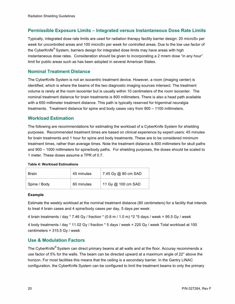
Workload Estimation The following are recommendations for estimating the workload of a CyberKnife System for shielding purposes. Recommended treatment times are based on clinical experience by expert users: 45 minutes for brain treatments and 1 hour for spine and body treatments. These are to be considered minimum treatment times, rather than average times. Note the treatment distance is 800 millimeters for skull paths and 900 – 1000 millimeters for spine/body paths. For shielding purposes, the doses should be scaled to 1 meter. These doses assume a TPR of 0.7.
Table 4: Workload Estimations
Brain 45 minutes 7.45 Gy @ 80 cm SAD
Spine / Body 60 minutes 11 Gy @ 100 cm SAD
Example
Estimate the weekly workload at the nominal treatment distance (80 centimeters) for a facility that intends to treat 4 brain cases and 4 spine/body cases per day, 5 days per week:
4 brain treatments / day * 7.46 Gy / fraction * (0.8 m / 1.0 m) ^2 *5 days / week = 95.5 Gy / week
4 body treatments / day * 11.02 Gy / fraction * 5 days / week = 220 Gy / week Total workload at 100 centimeters = 315.5 Gy / week
Use & Modulation Factors The CyberKnife® System can direct primary beams at all walls and at the floor. Accuray recommends a use factor of 5% for the walls. The beam can be directed upward at a maximum angle of 22° above the horizon. For most facilities this means that the ceiling is a secondary barrier. In the Gantry LINAC configuration, the CyberKnife System can be configured to limit the treatment beams to only the primary

Radiation Shielding Guidelines
P/N 027264, Rev F 21
barriers that were designed for the previous LINAC installation. In such an installation, for shielding calculations, the rest of the walls can be treated as secondary barriers.
Accuray recommends a modulation factor (MU per cGy) of 15 for head and spine/body paths. Figure 2 on the next page shows the target location and the position of the back of the waveguide for a CyberKnife device.
Figure 2: LINAC Dimensions
Key to Figure 2
A = Robot Joint 6 Axis B = Gun Plane C= Target Point
TVL Values Rogers, et al. have used Monte Carlo techniques to estimate TVLs (primary beam) for use with the CyberKnife® System. Accuray recommends using the equilibrium values (TVLe) from the table below.

Radiation Shielding Guidelines
22 P/N 027264, Rev F
Table 5: TVL Values
TVL data for ordinary concrete and lead. 1Ordinary concrete composition NBS04 as given by Rodgers.4
Density (g/cm3) 2.35 2.35 11.34 11.34
SDD 4.8 m 6.8 m 3.3 m 5.3 m
TVL1 (cm) 29.4 31.2 4.8 5.1
TVLe (cm) 31.9 32.4 5.05 5.25
Leakage Rates The CyberKnife System LINAC is shielded to limit the leakage around the LINAC to an average of about 0.03% of the primary beam. Maximum value of leakage rate at distance of 1 meter from the electron beam path is limited to 0.1% of the primary beam dose rate at 80 cm from the x-ray target as measured as an average over an area no greater than 10 cm x 10 cm. Both leakage and TVL values are smaller around the back of the LINAC. Leakage TVLe around the rest of the LINAC is 29.2 +/- 0.4 cm of concrete. Typically only 50% of the leakage dose value is comprised of radiation that is of sufficient energy to penetrate more than one TVL of concrete. See Accuray Shielding White Paper P/N 500627.A for details on the use of “high energy leakage” value for shielding calculations.
Groundshine Radiation Groundshine radiation may be a problem under any direct shielded doors or secondary shielded walls. Please refer to Page 82 of the NCRP report 151 mentioned below for more information.
CyberKnife® Shielding Publications Shielding White Paper, Part Number: 500627.A (contact Accuray, or download from Site Planning page at www.accuray.com)
NCRP report 151 has dedicated sections on CyberKnife® System shielding (section 7.2 and section 5.7). http://www.ncrppublications.org

P/N 027264, Rev F 23
3. ROOM SPECIFICATIONS
3.1 Treatment Room Treatment Room Size Specifications The CyberKnife System can be installed with two different types of shielding layouts:
• Standard CyberKnife Vault layout shielding • Gantry LINAC Vault layout shielding with or without inferior wall
Standard CyberKnife Vault Layout Shielding
Gantry LINAC Vault Layout

Room Specifications
24 P/N 027264, Rev F
Gantry LINAC Vault Layout with optional Inferior Wall
Figure 3: Shielding Layouts
Furthermore, each shielding layout can be installed in three different sizes of floor space and/or ceiling height:
Recommended Size
• Ideal amount of space for the CyberKnife® System to operate • Provides ample space for a sink, counters and storage cabinets
Minimum Size
• Minimum size that will fully accommodate the CyberKnife System • Provides minimal space for a sink, counters and storage cabinets
Absolute Minimum Size
• Absolute minimum amount of space to accommodate the CyberKnife System • Provides little to no additional space for a sink, counters and storage cabinets
Table 6: Summary of Available CyberKnife System installation layouts
Standard CyberKnife Shielding Conventional Gantry LINAC Shielding
Recommended Floor Space Recommended Floor Space
21’ X 22’ X 9’10” 21’ X 22’ X 9’10”
6.4m X 6.7m X 3.0m 6.4m X 6.7m X 3.0m
Minimum Floor Space Minimum Floor Space
18’ X 19’ X 9’10” 18’ X 19’ X 9’10”
5.5m X 5.8m X 3.0m 5.5m X 5.8m X 3.0m

Room Specifications
P/N 027264, Rev F 25
Absolute Minimum Floor Space Absolute Minimum Floor Space
16’ X 19’ X 9’ 16’ X 19’ X 9’
4.88m X 5.8m X 2.74m 4.88m X 5.8m X 2.74m
Table 7: Benefits and Limitations of Installation Layout
Treatment Vault Types
Potentially reduced shielding
costs
Potentially reduced time to
“Go Live”
Minimum size
Equipment Room
Full Treatment Node Set
Compatible with
RoboCouch
Possible incompatibility
with some future
upgrades
Conventional Gantry LINAC Shielding
1. Small Footprint (16’X19’X9’) (4.88 X5.8m X2.74m)
Yes Yes Yes Yes
2. Standard Footprint (18’X19’X9’10”) (5.49mX5.79mX3m)
Yes Yes Yes Yes Yes
CyberKnife Shielding
3. Small Footprint (16’X19’X9’) (4.88mX5.8mX2.74m)
Yes Yes Yes
4. Standard Footprint (18’X19’X9’10”) (5.49mX5.79mX3m)
Yes Yes Yes
Room Specifications
26 P/N 027264, Rev F
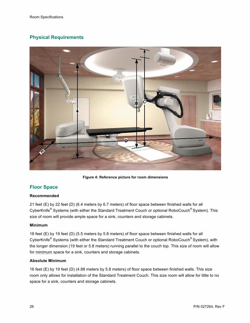
Physical Requirements
Figure 4: Reference picture for room dimensions
Floor Space Recommended
21 feet (E) by 22 feet (D) (6.4 meters by 6.7 meters) of floor space between finished walls for all CyberKnife® Systems (with either the Standard Treatment Couch or optional RoboCouch® System). This size of room will provide ample space for a sink, counters and storage cabinets.
Minimum
18 feet (E) by 19 feet (D) (5.5 meters by 5.8 meters) of floor space between finished walls for all CyberKnife® Systems (with either the Standard Treatment Couch or optional RoboCouch® System), with the longer dimension (19 feet or 5.8 meters) running parallel to the couch top. This size of room will allow for minimum space for a sink, counters and storage cabinets.
Absolute Minimum
16 feet (E) by 19 feet (D) (4.88 meters by 5.8 meters) of floor space between finished walls. This size room only allows for installation of the Standard Treatment Couch. This size room will allow for little to no space for a sink, counters and storage cabinets.

Room Specifications
P/N 027264, Rev F 27
NOTE: Using the absolute minimum dimension could possibly limit the number of available system upgrades in the future. Currently, all available products are compatible with this room dimension with the exception of the RoboCouch Patient Positioning System.
NOTE: The CyberKnife System equipment within the Treatment Room does not take up the entire square footage of the 18 feet by 19 feet (5.5 meters by 5.8 meters) or 16 feet by 19 feet (4.88 meters by 5.8 meters), but does use the majority of space within this area depending upon the configuration of the system. The Accuray customer Site-Specific Floor Plan drawing will show the customer where it is safe to install sinks, cabinets and other pieces of customer supplied equipment within the room.
NOTE: The center of the Treatment Manipulator must be at least 66 inches (1676 millimeters) away from any wall, column or other obstruction, in order to allow the manipulator to freely move during system operation.
NOTE: The room dimensions mentioned above only include the floor space of the actual Treatment Room and do not include any floor space dedicated to a maze walkway or the swing path of a direct-shielding door.
Ceiling Cap Height Recommended
11 feet (C) or greater (3.35 meters or greater) height between finished floor and rough ceiling cap (whether concrete or steel). This will allow for plenty of room for HVAC, lighting, etc. to be located between the finished ceiling and the ceiling cap.
Minimum
10 feet (C) (3.05 meters) between floor and rough ceiling cap.
Absolute Minimum
9 feet 2 inches (C) (2.8 meters) between floor and rough ceiling cap.
NOTE: Using the absolute minimum dimension could possibly limit the number of available system upgrades in the future. Currently, all available products are compatible with this room dimension with the exception of the RoboCouch® System.
Finished Ceiling Height Minimum (within Treatment Manipulator Operating Area)
9 feet 10 inches (B) (3 meters) height between the finished floor and the finished ceiling within the Treatment Manipulator operating area [13 foot (3.97 meter) diameter circle centered on isocenter]. Please see the Site-Specific Clearance and Elevation drawing for representation of this circle.
Absolute Minimum (within Treatment Manipulator Operating Area)
9 feet (B) (2.743 meters) height between finished floor and finished ceiling within the Treatment Manipulator operating area [13 foot (3.97 meter) diameter circle centered on isocenter]. Please see the Site-Specific Clearance and Elevation drawing for representation of this circle.
Room Specifications
28 P/N 027264, Rev F
NOTE: Using the absolute minimum dimension could possibly limit the number of available system upgrades in the future. Currently, all available products are compatible with this room dimension with the exception of the RoboCouch® Patient Positioning System.
Minimum (over Treatment Manipulator and Xchange® Table)
9 feet (A) (2.743 meters) height between finished floor and finished ceiling outside of the Treatment Manipulator operating area, directly over the back of the Treatment Manipulator and over the Xchange® Table. Please see the Site-Specific Clearance and Elevation drawing for representation of this area.
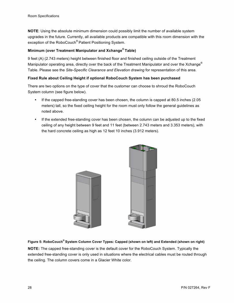
Fixed Rule about Ceiling Height if optional RoboCouch System has been purchased
There are two options on the type of cover that the customer can choose to shroud the RoboCouch System column (see figure below).
• If the capped free-standing cover has been chosen, the column is capped at 80.5 inches (2.05 meters) tall, so the fixed ceiling height for the room must only follow the general guidelines as noted above.
• If the extended free-standing cover has been chosen, the column can be adjusted up to the fixed ceiling of any height between 9 feet and 11 feet (between 2.743 meters and 3.353 meters), with the hard concrete ceiling as high as 12 feet 10 inches (3.912 meters).
Figure 5: RoboCouch® System Column Cover Types: Capped (shown on left) and Extended (shown on right)
NOTE: The capped free-standing cover is the default cover for the RoboCouch System. Typically the extended free-standing cover is only used in situations where the electrical cables must be routed through the ceiling. The column covers come in a Glacier White color.
Room Specifications
P/N 027264, Rev F 29
Minimum Door Clearance For rigging in equipment from the shipping truck to inside the Treatment Room, door clearances for the rig path need to be:
Recommended
48 inches wide by 84 inches tall (1219 by 2134 millimeters).
Minimum
43 inches wide by 84 inches tall (1092 by 2134 millimeters).
NOTE: There are some floor space clearances required for rigging in the Treatment Manipulator and RoboCouch® System (if purchased). Accuray can help to assess suitability of rigging path.
Recommended Equipment Orientations within the Treatment Room Because of the flexibility of orienting the CyberKnife® System within a vault, Accuray will help to determine the best orientation for your site based on:
• Ease of patient loading • Exact system configuration • System clearances • Shielding considerations • Ease of access to sinks and cabinets • Customer preferences
Please contact your Site Planner or Designer if you have any questions during the design process.
3.2 Control Room Minimum Floor Space 100 square feet (9.3 square meters), with enough counter space for at least 2 people and 3 to 4 workstations. This room should be large enough to easily accommodate four to five people during any training and Go-Live activities.
Recommended Location The Control Room should be located within eyesight of the Treatment Room door, and should be shielded from public view as much as possible.
Minimum Door Clearance For moving workstations into the Control Room, any typical door clearance is acceptable.
NOTE: If the Equipment Room is located off of the Control Room, any doors into the Control Room must meet the same minimum door clearance as the Equipment Room.

Room Specifications
30 P/N 027264, Rev F
3.3 Equipment Room Recommended Floor Space 160 square feet (15 square meters) if the X-ray Generators are located in the Equipment Room.
145 square feet (13.5 square meters) if the X-ray Generators are located outside of the Equipment Room.
Minimum Floor Space 145 square feet (13.5 square meters) if the X-ray Generators are located in the Equipment Room.
130 square feet (12 square meters) if the X-ray Generators are located outside of the Equipment Room.
NOTE: No side of the Equipment Room should be less than 7 feet (2.1 meters) long, in order to provide adequate installation and service access to the equipment. This rule changes to 10 feet (3.05 meters) for Equipment Rooms with the Minimum Floor Space.
Fixed Rule about Floor Space Additional floor space must be built into the Equipment Room for any customer-supplied equipment such as transformers, power conditioners (voltage stabilizers), floor mounted air conditioning units, data and server equipment, phone equipment, storage cabinets, etc. Service access and regulatory requirements must be considered when planning for adequate space around each piece of Accuray or customer-supplied equipment.
Recommended Location Due to limited cable lengths between most equipment, the Equipment Room should be located adjacent to the Treatment Room, and as close to the Treatment Manipulator as possible.
NOTE: As a rule of thumb, the maximum cable length run from the Treatment Manipulator pull box to the Equipment Room pull box should be no more than 30 feet (9.1 meters).
Fixed Rule about Location System operators must be able to access the Equipment Room during patient treatment. The equipment in the Equipment Room (with the exception of the X-ray Generators) can not be located in the Treatment Room, nor can they be located in a room that is entered into by going through the Treatment Room, nor can they be located on a different floor from the Control Room.
Minimum Finished Ceiling Clearance 7 feet (2.135 meters) between finished floor and finished ceiling.
Minimum Door Clearance 3 feet wide by 7 feet high (.914 by 2.134 meters) for rigging the equipment into the Equipment Room, door clearances for the rig path need to be a standard.
NOTE: The Equipment Room door(s) must be lockable, so that the room can not be accessed during treatment by anyone other than the operators.
Room Specifications
P/N 027264, Rev F 31
3.4 Treatment Planning Room(s) Workspace Enough workspace for two or more workstations and a desktop color laser printer. Accuray will attempt to show the exact number of purchased workstations on the customer Site-Specific Drawings. Otherwise, we will show a generic setup. Please contact your Accuray Site Planner for additional information.
Recommended Location The Treatment Planning Room should be located within 328 feet (100 meters) network cable run length to the Equipment Room. This will facilitate better I.T. connection speeds, as it will allow direct connection between the workstations located in this room and the CyberKnife® System internal network.
Locating the Treatment Planning Room at a further location will require connecting the workstations and printer to the facility network and may significantly slow down the transfer speed of treatment plans. Please see the I.T. section of this document, or Accuray’s IT Guide (Part Number 025168) for more information.
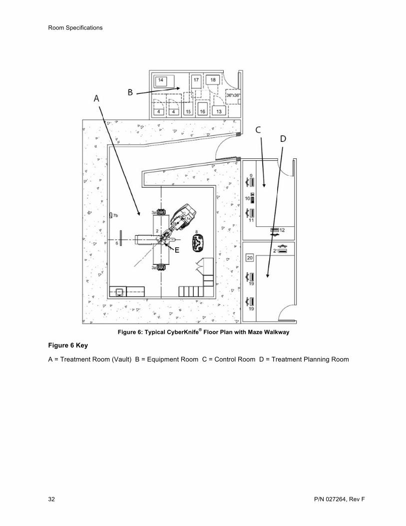
3.5 Sample Drawings The following two illustrations show two typical floor plan layouts. For a complete package of sample drawings and design details, please contact your Accuray Site Planner.
Room Specifications
32 P/N 027264, Rev F
Figure 6: Typical CyberKnife® Floor Plan with Maze Walkway
Figure 6 Key
A = Treatment Room (Vault) B = Equipment Room C = Control Room D = Treatment Planning Room
Room Specifications
P/N 027264, Rev F 33
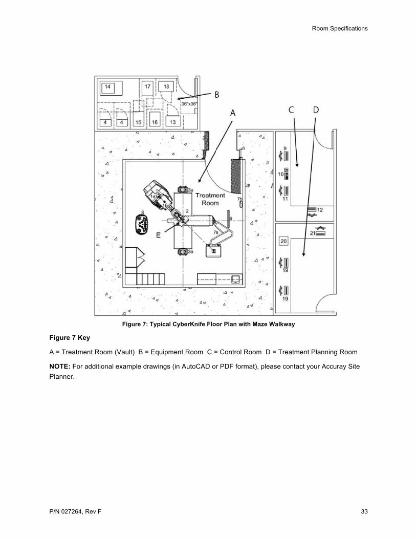
Figure 7: Typical CyberKnife Floor Plan with Maze Walkway
Figure 7 Key
A = Treatment Room (Vault) B = Equipment Room C = Control Room D = Treatment Planning Room
NOTE: For additional example drawings (in AutoCAD or PDF format), please contact your Accuray Site Planner.

34 P/N 027264, Rev F
4. ELECTRICAL AND ENVIRONMENTAL REQUIREMENTS
4.1 Electrical Power Requirements It is recommended to supply 480 VAC, 3-phase, 100 Amps, 55 kVA power to the Main Power Disconnect. However, the CyberKnife® System Power Distribution Unit (PDU) will accept input power in the range of 200 VAC through 480 VAC. For any input voltages at 240 VAC and below, 150 Amps is required.
The Main Power Disconnect typically needs a 36 inch square (914 millimeter square) exclusionary area directly in front of it for regulatory requirements. We recommend that it be located next to the door of the Equipment Room, with the Junction Box located between the Main Power Disconnect and the door. The customer is responsible for the Disconnect box, fuses and all conduits and wiring from the original power source to the box. Accuray will supply and run the power cable from the Disconnect Box to the CyberKnife System PDU. The CyberKnife System does not use a neutral leg. A grounding lug is to be supplied by the electrical contractor with the following specifications: A 4 gauge lug terminating to grounded building steel or earth within the main power disconnect.
The Main Disconnect can be located on an outside wall of the Equipment Room, as long as it remains within the cable limitations of the PDU. Accuray can help to locate the best position.
Power Conditioner (Voltage Stabilizer) A power conditioner will be required of the customer if the input voltage can not be regulated to within +/- 5% phase to phase. Please see Section 5.6: Power Conditioners for more information.
Uninterruptable Power Supply (UPS) A UPS is provided to power the Treatment Delivery, Data Server, LCD monitor and networking devices in the event of a power failure to reduce risk of lost or damage to data.
A UPS is not provided for other workstations such as the Multiplan®
MD suites, Administrative Workstation, and etc. Although not required, it is recommended and customer may at its discretion and expense provide additional UPS to protect these devices.

Electrical and Environmental Requirements
P/N 027264, Rev F 35
4.2 Environmental Treatment Room The Treatment Room should be kept between 50° F and 85° F (10° C and 30° C), twenty-four hours per day, seven days per week, with a range of 30 to 70% relative humidity.
The heat generated by the equipment in the Treatment Room is:
Table 8: Treatment Room Cooling Specifications
ITEM DESCRIPTION BTLU/h Kilowat
1a Treatment Manipulator 0 0
1b Linear Accelerator 0 0
1c Interchangeable Secondary Collimators 0 0
1d Treatment Manipulator Teach Pendant 0 0
1e IrisTM Collimator (Optional) 0 0
2 In-Floor Image Detectors (Quantity=2) 1230 .36
3a X-ray Sources (Quantity=2) 0 0
3b X-ray Source Heat Exchangers (Quantity=2) 2400 .7
4 X-ray Generators (Quantity=2) (may be located in another room)
1100 .322
5 Standard Treatment Couch 0 0
6 Synchrony® System Camera 0 0
7a RoboCouch® System (Optional) 0 0
7b RoboCouch System Wall Module (Optional) 0 0
8 Xchange® Changer (Optional) 0 0
Total with X-ray Generators in Treatment Room 4730 1.382
Total without X-ray Generators in Treatment Room 3630 1.06

Electrical and Environmental Requirements
36 P/N 027264, Rev F
Control Room There are no special requirements with regard to the CyberKnife® System in the Control Room.
Equipment Room Because the CyberKnife System is kept running at all times, the Equipment Room must be kept between 50° F and 75° F (10° C and 24° C), with a range of 30 to 70% relative humidity, twenty-four hours per day, seven days per week. The heat generated by the equipment in the Equipment Room is:
Table 9: Equipment Room Cooling Specifications
ITEM DESCRIPTION BTU/h KW
4 X-ray Generators (Quantity=2) (may be located in another room)
1100 .322
13 Controller (for Treatment Manipulator) 4700 1.377
14 Modulator 11600 3.4
15 Computer Rack 3800 1.114
16 Power Distribution Unit (PDU) Rack 2600 .762
17 Mechanical Rack 6300 1.85
18 Controller (for RoboCouch System) 4700 1.377
DESCRIPTION TOTAL BTU/h TOTAL KW
Total without X-Ray Generators in Equipment Room, and without optional RoboCouch® Controller
29000 8.5
Total with X-ray Generators in Equipment Room, and without optional RoboCouch Controller
30100 8.825
Total without X-ray Generators in Equipment Room, and with optional RoboCouch Controller
33700 9.88
Total with X-ray Generators in Equipment Room, and with optional RoboCouch Controller
34800 10.2

Electrical and Environmental Requirements
P/N 027264, Rev F 37
NOTE: We recommend planning for the maximum capacity of the room (34,800 BTU/h or 10.2 Kilowatts) in case the additional options are installed at a later date. Most of our customers install a minimum 3 ton air conditioner to achieve the cooling needs of this room.
Cooling requirements for the Equipment Room are between 30,000 and 35,000 BTU/h (8.8 to 10.26 Kilowatts), depending upon whether the X-ray Generators are located in the room and if the RoboCouch System has been purchased (which requires an additional controller). We recommend all sites plan for the RoboCouch System, as the customer may upgrade to it at a later date. Typically, our customers install a minimum three ton air conditioning unit for this room. Please see Section 4: Electrical and Environmental Requirement for more information.
Treatment Planning Room(s) There are no special requirements with regard to the CyberKnife® System for the Treatment Planning Rooms.
System Storage (Non-operating condition) Guidelines If the CyberKnife System must be stored for any length of time in a crated or uncrated condition, please follow these guidelines:
• Store in an environmentally protected indoor area free from dust and any potential water damage • Make sure the area is temperature controlled between 40° F and 90° F (5° C and 32° C) • Assure the area is humidity controlled to less then 80%, non-condensing • Assure the area is locked to prevent against vandalism
NOTE: Approximately 400 square feet (37.2 square meters) is needed for storing a crated CyberKnife®
System.

38 P/N 027264, Rev F
5. OTHER SYSTEM IMPLEMENTATION CONSIDERATIONS
5.1 Pre-Installation Process Contents of Shipping Crates The pre-install kit crates contain the fiberglass imaging tub, the Treatment Manipulator floor frame, the RoboCouch® System floor frame (although in rare circumstances, it may not be installed), the X-ray Source ceiling mount kits, Synchrony® System ceiling mount kit, emergency off and key switches, a dolly and other related hardware.
For any rigging or storage purposes, the crate measurements are typically:
Table 10: Pre-Install Crate Measurements and Weights
CRATE CONTENTS LENGTH WIDTH HEIGTH WEIGHT
Large Fiberglass Tub 127 inches 3226 mm
44 inches 1118 mm
22 inches 559 mm
582 lbs 264 kgs
Medium Treatment Manipulator Frame
73 inches 1854 mm
48 inches 1219 mm
16 inches 406 mm
655 lbs 297 kgs
Small RoboCouch Frame 36 inches 29 inches 17 inches 250 lbs
914 mm 737 mm 432 mm 114 kgs
Shipping and Rigging The pre-install kit crates are normally shipped to the site when the floor pit is ready – typically at least four to five weeks before construction is completed and the CyberKnife®
System is delivered. Accuray will schedule and pay for the shipment of the three crates to the customer location. We ask that the customer or their contractor receive the shipment and store it in a safe area until Accuray personnel arrive to unpack the crates and move the material into the CyberKnife System suite area. If stacking the crates, please place the medium and small crates on the ground, and stack the large crate on top.
Site Preparation The pre-install kit should be installed in the window of time between the completion of construction on the raw concrete vault (or demolition if renovating a vault) and the point just before finished walls and ceiling, and any ceiling work (HVAC, sprinklers, lighting, etc.) begin to be added.
Accuray will need access to the ceiling cap (concrete or steel) for anchoring (or welding for steel ceilings) our X-ray Source unistruts and plates, and Synchrony® plate and pole (please see Site-Specific Pre-Installation plan for locations) We will also need the floor pit completed and cleaned out of any trash

Other System Implementation Considerations
P/N 027264, Rev F 39
and/or water. The rest of the inside of the vault should be as empty of material as possible to allow free movement of ladders, tools and equipment by Accuray. The conduits and pull boxes for the Treatment Manipulator and RoboCouch® frames will need to have been installed.
Tools and labor that Accuray will need the contractor to supply are:
• Ladder of sufficient height to do ceiling work (power lift for ceilings over twelve feet) • Electricity for hand tools (typically 120VAC in the US, or equivalent internationally) • Wet/Dry vacuum • Portable lighting for safe work • Hard hats, vests and safety glasses if required • Basic cooling/heating as necessary if temperatures are extreme • Dust ventilation, as required • Additional labor (1 to 2 people) for a few minutes to help lift and install the floor frames onto the
anchors
Accuray Pre-Installation Process During this process, Accuray (or an approved contractor) will complete the following:
• Locate Isocenter within the room and verify measurements to all walls
• Lay templates on the bottom of the floor pit to mark locations of anchors for both floor frames and the ceiling installation work (plates and unistruts)
• For ceiling work, Accuray will drill and place four Hilti concrete anchors for each plate, install the plates/unistruts and secure to the anchors. The unistruts will be cut to the proper length to support the X-ray Sources (to be installed during system installation).
• Accuray will drill and place anchors in the bottom of the floor pit for both floor frames. Accuray will install the frames (with additional labor help as needed) onto the anchors and then level and secure the frames to the anchors. The Treatment Manipulator frame weights 350 pounds (159 kilograms) and the RoboCouch® frame weights 192 pounds (87 kilograms).
• Accuray will then install the fiberglass tub inside the pit, leveling and anchoring it to the concrete floor. A conduit connector will be installed between the Treatment Manipulator floor frame and the tub and secured with duct tape.
• All bolt holes in the frames and any connections between pieces will be secured with duct tape to prevent any concrete paste from seeping through.
• All pads on the frames will be marked to indicate where their level should end up in relation to the poured concrete floor. Some will be marked ¼” (6 to 7 millimeters) above finished floor (assuming standard vinyl flooring – if non-standard flooring, such as ceramic tiles are installed then this number will change) and others marked flush with finished floor. When poured, the top of the finished concrete floor should be flush with the outer lip of the fiberglass tub (please see Accuray Site-Specific Drawings for more information).

Other System Implementation Considerations
40 P/N 027264, Rev F
Customer / Contractor Follow-up Work The contractor will be responsible for the following:
• Securing a connection between the rectangle conduit coming out of the back of the Treatment Manipulator floor frame and the contractor’s pull box. The wall of the box around the conduit should be securely sealed so that concrete from the pit doesn’t flow into the pull box.
• Pouring concrete into the pit as soon as possible to reduce the chance of the frames or fiberglass tub from accidentally being altered from their correct position.
• Pouring concrete as easily as possible around the fiberglass tub to avoid any warping or movement of the tub walls or top rim. Make sure that the concrete/grout flows completely under the tub – a vibrator may need to be used.
The electrician will be responsible for the following:
• Installing the EPO, EMO, Door Override Key Switch and X-Ray On light relay (if needed). For the EPO, EMO and Door Override Key Switch, Accuray supplies the push buttons, switches and labels. The electrician supplies the single gang boxes, covers, conduits, wiring and installation.
Additional Site Work by Accuray After the pre-installation work is completed, Accuray will:
• Inspect and measure all cable conduits to make sure lengths are per the drawings • Inspect the Equipment Room to make sure that all Power Distribution Boxes, pull boxes and other
customer supplied equipment (HVAC, Power Conditioners, etc.) are in the locations per the plans • Walk the rig route that the CyberKnife® System will take to measure clearances and assure
adequate staging area at the location the equipment will be taken off of the shipping truck. • Be available to answer any questions.
5.2 CyberKnife® Shipping and Rigging Considerations CyberKnife System Contents The following table lists typical crate measurements for any rigging or storage purposes.
Table 11: CyberKnife® System Crate Measurements and Weights
CONTENTS
DIMENSIONS INS DIMENSIONS MMS
WEIGHT LBS WEIGHT KGS
1 Treatment Manipulator 96” x 60” x 89” 2438x1524x2261
3,836 lbs 1,740 kgs
2 Controller 29” x 38” x 65” 737x965x1651
592 lbs 269 kgs
3 Standard System Cables / Sub Systems 46” x 67” x 29” 1168x1702x737
418 lbs 190 kgs

Other System Implementation Considerations
P/N 027264, Rev F 41
4 System Covers 50” x 94” x 50” 1270x2388x1270
650 lbs 295 kgs
5 System Covers 43” x 79” x 26” 1092x2007x660
296 lbs 134 kgs
6 Detector Base Frame 33” x 115” x 12” 838x2921x305
242 lbs 110 kgs
7 Double Bay Rack, PARS, Printer, MultiPlan® System
49” x 86” x 86” 1245x2184x2184
1,500 lbs 680 kgs
8 Chiller 37” x 48” x 64” 940x1219x1626
612 lbs 278 kgs
9 PDU 34” x 42” x 62” 864x1069x1575
1,176 lbs 533 kgs
10 Modulator and LINAC boxes 48” x 86” x 60” 1220x2185x?
1,750 lbs 794 kgs
11 LINAC Head 48” x 86” x 54” 1220x2185x1372
780 lbs 354 kgs
12 X-ray Sources and X-ray Generators 48” x 86” x 60” 1220x2185x1524
1,238 lbs 562 kgs
13 Generator Covers and Detectors 49” x 86” x 60” 1245x2184x1524
630 lbs 286 kgs
14 Imaging Tub Components, Lead Shielding
47” x 86” x 39” 1194x2184x991
1,014 lbs 460 kgs
15 Ladder 32” x 110” x 20” 813x2794x508
150 lbs 68 kgs
16 QA Tools, Documentation and Software 47” x 66” x 39” 1194x1676x991
372 lbs 169 kgs
17 Secondary Collimators 30” x 20” x 14” 762x508x356
170 lbs 77 kgs
NOTE: These measurements and weights may vary or change over time.
Shipping and Rigging The CyberKnife System is normally shipped to arrive at the site around 7:00AM on the first day of the scheduled installation, typically a Tuesday. However, other days of the week and times can be scheduled according to what works best for the customer and Accuray.
Unless the contract calls for another arrangement, Accuray will schedule and pay for the shipment of the system crates to the customer location.

Other System Implementation Considerations
42 P/N 027264, Rev F
The customer contract will determine whether the customer or Accuray is responsible for scheduling and paying for the rigging of the system from the shipping truck into the customer facility. The Accuray site planner can answer any questions the customer has on rigging responsibility.
If Accuray is responsible for the rigging, we will typically use our shipping company as the rigger for the job. Accuray will be responsible for the first $8,000 of the rigging costs, which represents a typical rig job. The customer will be responsible for the remainder of the cost (this typically occurs if a crane or other special equipment is required). If the customer is responsible for the rigging, our shipping company is available to do the rigging for a fee. We do recommend this option, as they are the most familiar with our equipment and the rigging needs of transporting the equipment into your facility. Your Accuray Site Planner can help to get you in touch with the right contact person at our shipping company.
If you would like to arrange to have the rigging done by a local company, listed below is the manpower and equipment that will be needed for the rig-in:
Rig-in Manpower and Equipment Needed Manpower
• One experienced rigger, two additional movers. • Our installers will be present to help answer questions and assist with some work.
Equipment
• An 8,000 pound (3600 Kg) forklift with 8 foot (2.4 meter) fork blades • One electric two-ton pallet jack • One hand-operated genie lift (>300 lbs capacity)(136 kg) • One J-bar • Eight (8) four-wheel dollies • Two metal plates for crossing doorways • Floor protection for the length of the route (masonite or lexan sheets 4 foot by 8 foot)(1.2 meter
by 2.4 meter). The heaviest piece to move is the Treatment Manipulator at 2,850 lbs (1,293 Kg). • Basic tools for uncrating the equipment • Tarps to cover or “stage” the equipment if the weather is bad • Straps
NOTE: Because the rig-in typically starts at 7:00AM, the rigging equipment will need to be delivered either before 7:00 AM or the night before (preferred).
5.3 CT Scanners Used for Patient Imaging CT scanner Selection The CyberKnife® System has been designed to deliver patient treatment with sub-millimeter accuracy. In order to ensure this high level of patient care and treatment, the image data sets that are sent from the customer’s CT scanner(s) to the CyberKnife System need to follow certain guidelines:

Other System Implementation Considerations
P/N 027264, Rev F 43
Minimum Requirements
A minimum 16-slice CT scanner should be used for Synchrony® cases. This will assure reasonably short scan times, high image quality, minimal fiducial movement, and minimum artifacts and movement due to patient breathing.
Minimum Requirements:
No more than 1.5 millimeter slice thickness must be used in order to maximize treatment accuracy.
NOTE: Variable slice thickness cannot be used with the CyberKnife® System.
Minimum Requirements:
Slice quantity: A maximum of 512 slices should be taken for Extra-Cranial (EC) cases.
4D Software Option:
If the customer has purchased Accuray’s 4D software option, they must have a CT scanner with a 4D option, as well. The current CT scanners supported by this option are:
• GE Discovery ST • Siemens Sensation Open • Philips Brilliance Big Bore
NOTE: If your facility’s CT scanner(s) cannot meet any of the requirements listed above, or you have any questions about these guidelines, please contact your Accuray Account Manager or Site Planner for more information.
CT Overlay Kits Each CT scanner used to supply image data sets to the CyberKnife System must have a flat overlay for the CT cradle, a 2 inch (51 millimeters) thick pad and a CIVCO base plate. These need to be present on the CT scanner at the time of system installation. They should be ordered well in advance of the installation, as lead times with the manufacturer can be as long as eight weeks.
Overlay tops are not needed for other modalities used during treatment planning, such as MRI, Angio or PET.
5.4 Information Technology Needs IP Addresses Three static IP addresses within the same subnet needed. One IP assigned to Cisco router as Management IP. The second IP also assigned to Cisco router as Forwarding IP. The third IP is assigned to the service technician for network access.
Additional static IP addresses may be needed for CyberKnife® workstations or printers that reside outside of the CyberKnife LAN.

Other System Implementation Considerations
44 P/N 027264, Rev F
Facility Network Ports Typically two are needed; one dedicated port in the Equipment Room near the equipment rack and one port in the Control Room that has (at least temporary) internet access.
Dedicated Network Ports For each system (MultiPlan®, MD Suite, CyberKnife System Administrative Workstation) and printer that resides within 328 feet (100 meters) of cable distance to the Equipment Room, we require a dedicated Cat-6 network cable to be run from the System to the Equipment Room (near the equipment rack). This will allow the system to be directly connected to the CyberKnife System network. These typically reside in the Treatment Planning Room or physicist’s office. Your Accuray Site Planner can help to define the number of systems that fall into this category. An example would be:
• Standard MultiPlan System • Standard or Optional MultiPlan System (depending upon contract) • Standard Color Laser Printer • Optional MultiPlan System • Optional MD Suite • Optional MD Suite • Additional Workstations for Future Growth • Additional Workstations for Future Growth
For more information, please see Accuray’s Installation I.T. Guide (Part Number 025168). Your site planner can provide this document to you.
Internet Access Requirements CyberKnife® PCs and workstations require Internet access to transfer diagnostic logs and enable remote access and remote management of CyberKnife devices. The following is a list of destination IP addresses and port requirements that needs to be setup or allowed through the customer’s network devices, firewalls, or routers. Enabling or permitting these specific communication rules allow Accuray Engineers to quickly obtain diagnostic logs and remote access to CyberKnife devices to resolve issues quickly that otherwise would take much longer or require a service technician to be onsite.
SOURCE DESTINATION PORT
CK-Mgmt-IP Field service e-mail access 80, 443
CK-Mgmt-IP FTP file transfers 21
CK-Mgmt-IP FTPS command/auth port 990
CK-Mgmt-IP FTPS data ports 2000 - 2010
CK-Mgmt-IP GotoAssist, GotoMyPc access 80,443,8000

Other System Implementation Considerations
P/N 027264, Rev F 45
CK-Mgmt-IP Axeda remote management 80, 443
CK-Mgmt-IP www.verisign.com 80, 443
CK-Mgmt-IP Ghsom1.axeda.com 443
CK-Mgmt-IP Ghuk1.axeda.com 443
CK-Mgmt-IP Ghjap1.axeda.com 443
CK-Mgmt-IP Ghsj1.axeda.com 443
Source CK-Mgmt-IP is the management IP of the Cisco router, which is to be determined by Network administrator and installation team.
Please contact Accuray Technical Support ([email protected]) for exact destination IP addresses.
NOTE: The IT setup work must be completed ahead of system delivery.
5.5 Sulfur Hexafluoride (SF6) Gas The customer is responsible for supplying one cylinder of chemically pure SF6 gas for use with the CyberKnife® System.
Equipment Needed Bottle of SF6 gas: At least 99.9% pure. About 20-30 inches (500 to 760 millimeters) long and 7 inches (180 millimeters) in diameter. Approximately 60 pounds (27.2 Kilograms) of gas. But, larger sizes will be fine.
Common Suppliers • Concorde Specialty Gases, Inc. – (800) 818-5109 – www.concordegas.com • Air Liquide – (407) 548-5000 – www.airliquide.com • Praxair – (800) PRAXAIR (From within US) – (716) 879-4077 (From outside US) –
www.praxair.com
NOTE: The SF6 gas is needed prior to the start of the system installation, so it will need to be ordered at least one month ahead of time.
5.6 Power Conditioners The customer is responsible for purchasing and installing a power conditioner if the input voltage can not be regulated to within +/- 5% phase to phase.

Other System Implementation Considerations
46 P/N 027264, Rev F
Equipment Needed One power conditioner with voltage regulation.
Common Supplier Transtector - (800) 882-9110-www.transtector.com (they have a specific power conditioner identified for the CyberKnife® System)
5.7 Patient Positioning Lasers The customer is responsible for purchasing and installing the lasers for use with the CyberKnife System. While these lasers are not absolutely necessary, they are highly recommended.
There should be three lasers; two cross-hair lasers with the centerline located 36 1/4 inches (920.75 millimeters) off the finished floor, on either side of isocenter, and one sagital laser located 90 inches (2286 millimeters) off the finished floor, at the foot of the patient couch, with the laser pointed down the centerline of the couch top. The positions are called out on the Accuray Site-Specific Drawings.
Equipment Needed Two cross-hair lasers and one sagital laser.

Other System Implementation Considerations
P/N 027264, Rev F 47
Installation Locations
Figure 8: Laser Installation Locations
Figure 8 Key
L1 = Laser crosshair centered 36 ¼” (921 millimeters) above finished floor L2 = Laser beam centered 90” (2286 millimeters) above finished floor
Common Suppliers • LAP - (800) 498-2674 - www.lap-laser.com • Gammex – (800) 426-6391 - www.gammex.com • Diacor – (800) 342-2679 - www.diacorinc.com
NOTE: The lasers are installed and aligned after the CyberKnife® System has been installed. Typically they are installed prior to system Go-Live.
5.8 Intercoms Comprised of a microphone and speaker. The customer is responsible for purchasing and installing the intercom for use with the CyberKnife® System.

Other System Implementation Considerations
48 P/N 027264, Rev F
Equipment Needed One intercom base station for Control Room and one intercom hands-free speaker in the Treatment Room.
Common Suppliers • Aiphone - (800) 692-0200 - www.aiphone.com • Nutone – (888) 336-3948 - www.nutone.com
NOTE: The intercom needs to be installed prior to the CyberKnife System installation.
5.9 Closed Caption TV (CCTV) This is usually comprised of a quad multi-plex monitor, used for viewing the patient in the Treatment Room from at least four different angles, along with cameras located in the Treatment Room.
Accuray recommends a minimum of four cameras, with at least two of them having pan/tilt/zoom capabilities (recommend that all four have this capability).
Two cameras should be located at or on the finished ceiling, and the other two located at isocenter height, approximately 36 inches (914 millimeters) above finished floor to center of lens. If there is a maze walkway, it’s suggested to have a fifth camera focused on the walkway.
Impact-resistant dome cameras recommended for the lower cameras. Camera monitor, pan/tilt/zoom control, keyboard and speaker to be located in the Control Room. Camera locations and quantity are to be determined by the customer (typically the Physicist). The camera manufacturer, type and capabilities are to be selected by the customer. The customer is responsible for purchasing and installing the camera system for use with the CyberKnife® System. Please provide details to the Accuray Site Planner for approval of clearance and serviceability.
Equipment Needed Four cameras and suitable viewing station.
Common Suppliers • General Electric - (888) 437-3287 - www.gesecurity.com • Panasonic – www.panasonic/business/security.com • Samsung – www.samsungsecurity.com • Nuvico – (866) 523-1700 - www.nuvico.com
NOTE: The camera system needs to be installed prior to the CyberKnife System installation as it is used during system testing and calibration.
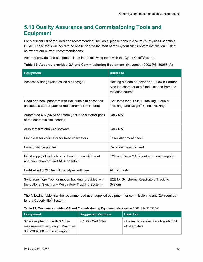
Other System Implementation Considerations
P/N 027264, Rev F 49
5.10 Quality Assurance and Commissioning Tools and Equipment For a current list of required and recommended QA Tools, please consult Accuray’s Physics Essentials Guide. These tools will need to be onsite prior to the start of the CyberKnife® System installation. Listed below are our current recommendations:
Accuray provides the equipment listed in the following table with the CyberKnife®
System.
Table 12: Accuray-provided QA and Commissioning Equipment (November 2008 P/N 500584A)
Equipment Used For
Accessory flange (also called a birdcage) Holding a diode detector or a Baldwin-‐Farmer type ion chamber at a fixed distance from the radiation source
Head and neck phantom with Ball-‐cube film cassettes (includes a starter pack of radiochromic film inserts)
E2E tests for 6D Skull Tracking, Fiducial Tracking, and Xsight® Spine Tracking
Automated QA (AQA) phantom (includes a starter pack of radiochromic film inserts)
Daily QA
AQA test film analysis software Daily QA
Pinhole laser collimator for fixed collimators Laser Alignment check
Front distance pointer Distance measurement
Initial supply of radiochromic films for use with head and neck phantom and AQA phantom
E2E and Daily QA (about a 3 month supply)
End-‐to-‐End (E2E) test film analysis software All E2E tests
Synchrony® QA Tool for motion tracking (provided with the optional Synchrony Respiratory Tracking System)
E2E for Synchrony Respiratory Tracking System
The following table lists the recommended user-‐supplied equipment for commissioning and QA required for the CyberKnife® System.
Table 13: Customer-provided QA and Commissioning Equipment (November 2008 P/N 500585A)
Equipment Suggested Vendors Used For
3D water phantom with 0.1 mm measurement accuracy • Minimum 300x300x300 mm scan region
• PTW • Wellhofer • Beam data collection • Regular QA of beam data

Other System Implementation Considerations
50 P/N 027264, Rev F
At least one calibrated Baldwin-‐Farmer type ion chamber with 6 MV buildup cap
• Per country-‐specific calibration protocol
• Absolute dose calibration • LINAC output measurements • Delivered dose measurements
Calibrated electrometer • Various • QA and beam data collection procedures involving ion chambers and/or diode detectors
Micro ion chamber • Standard Imaging Exradin A16 • PTW 31016 • Other equivalent
• Delivered dose measurements
Stereotactic diode detector • PTW 60012 • Sun Nuclear Edge Detector
• Beam data collection • Regular QA of beam data
Reference diode detector • Diode detector with approximately the same sensitivity as the stereotactic diode detector above
• Beam data collection • Regular QA of beam data
Phantom with: • plugs and holes for ion chamber and/or film inserts and/or TLDs • accurately known dimensions for structural features, insert pieces or fiducial marker locations • inhomogeneities (for Monte Carlo Dose Calculation option)
• Stereotactic Dose Verification Phantom from Standard Imaging (“Baby Blue”) • Tissue-‐equivalent slab phantoms with fiducials – multiple vendors
• Delivered dose verification • Geometric accuracy verification of CT scanner