realigning fm receivers - radiomuseum.org alignment... · chapter 13 realigning fm receivers 13-1....
TRANSCRIPT
C H A P T E R 13
REALIGNING FM RECEIVERS
13-1. Similarities to A M Superheterodyne Realignment
Although a number of special techniques are involved in FM-receiver realignment, differences between this procedure and that for other superheterodyne receivers should not be overemphasized. The F M superheterodyne receiver differs from the A M superheterodyne receiver only in the second-detector and limiter sections.
Realignment of the F M receiver need not be a highly complex process, and the technician who thoroughly understands the basic principles of this type of receiver will find realignment fairly simple, because he knows the reason for each step. Such knowledge permits short cuts and simple methods to substitute for expensive equipment and elaborate procedures.
For instance, while it is conceded that the most accurate method of F M receiver realignment is the visual method, many receivers can be satisfactorily realigned with an A M signal generator and a V T V M , without need for the oscilloscope and sweep generator.
Accordingly, realignment procedures which can be followed without visual realignment will be discussed first. This will serve the double purpose of helping the technician who has limited equipment and providing fundamental material upon which to base the later visual-realignment discussion.
The adjustments for realignment in an F M receiver are substantially the same as those found in A M superheterodynes. There are resonance adjustments on the i-f transformers, and trimmers and padders for the oscillator, mixer and r-f amplifiers. The important difference is found in the technique of adjustment of the last i-f transformer windings, which in the A M receiver couple the diode second detector to the i-f amplifier and in the F M receiver couple the F M detector section to the i-f amplifier (or limiter). Since the detector section provides the main differences between A M and F M procedures, the differences and special features involved in these circuits will be discussed first.
13-2. The Effect of F M Detector Circuits on FM-Receiver Realignment
The reason certain A M realignment procedures are not effective for F M realignment is the fact that limiting, or the similar effect in a ratio detector, is part of the F M receiving process.
444
S E C . 13-2] REALIGNING FM RECEIVERS • 445
Realignment procedures for A M receivers are concerned mainly with noting the a-j output voltage of the receiver and adjusting the various circuits for a maximum of this voltage. It is desirable in an F M receiver to adjust all front-end and i-f amplifier circuits for maximum i-f signal to the limiting stage. The a-f output signal does not vary appreciably with increases of the i-f signal above a certain threshold value and is therefore not useful for indication for r-f and i-f realignment adjustments.
Accordingly, when trimmers and padders etc. are adjusted in an F M receiver, the a-f output signal cannot ordinarily be used as an indicator of the condition of realignment.
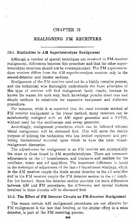
F I G . 13-1 Basic Foster-Seeley discriminator circuit. The primary winding of T2 is adjusted, with an unmodulated signal, for maximum d-c voltage across either R2 or R3. The secondary winding is adjusted for zero voltage across R2 and RS in series, in other
words, from point a to ground.
In addition, F M receivers in general are designed for as nearly as possible a "flat-top" response characteristic, so that the signal amplitude from the i-f amplifier will not vary because of frequency deviation during modulation. As was explained in Chapter 12, with such a response it is somewhat difficult to realign with only the maximum output of the stage as indicator, since the maximum will be obtained at any frequeftcy along the flat-top portion of the characteristic response curve. This explains the desirability of visual alignment. However, with some experience, a technician can do a rather accurate job with an A M generator, by "centering" the adjustment, as is explained later in this chapter.
Since the a-f output voltage is not a satisfactory indicator of the condition of realignment with an A M signal generator, the means of obtaining such an indication in standard circuits are important and wil l now be discussed.
First, consider the standard Foster-Seeley ("phase") discriminator and preceding limiter stage, as illustrated by the schematic diagram of Fig. 13-1. The signal from the i-f amplifier is applied to the limiter stage, which limits the output from this stage to a certain maximum value,

446 • RECEIVER TROUBLESHOOTING AND REPAIR [CHAP. 13
thus virtually eliminating amplitude variations from the signal applied to the discriminator circuit.
One of the functions of the limiter is to draw grid current for any signal applied to its input circuit. This grid current, passing through the grid resistor Rl, produces a bias voltage which is the IR drop across this resistor. The current amplitude, and thus the value of voltage across the resistor, are dependent upon the strength of the signal received from the i-f amplifier. Thus all realignment adjustments between the grid of the limiter and the antenna can be made using the voltage across the limiter-grid resistor as an indicator, and a maximum obtained for each. A l l alignment adjustments up to and through Tl are thus taken care of.
A position for an indicating meter for realignment of T2 must now be found in the discriminator circuit. The voltages across R2 and RS respectively both increase as the signal is tuned to resonance, but, since the voltages are in opposition, they combine in series to cancel each other and produce zero voltage at point a when the signal is exactly in resonance.
For the primary winding, the adjustment must be made for maximum signal transfer from the limiter to the discriminator. Thus, by connecting the V T V M across either R2 or R8 (but not both) the technician obtains a d-c voltage which varies with the amount of signal transferred from the limiter through T2 to the discriminator. This voltage is not an accurate indicator of realignment adjustments before the limiter circuit, since the limiter nullifies the effects of such adjustments. However, it is about the only convenient method of realigning T2 accurately without a visual setup.
The voltages across R2 and RS are, of course, d-c voltages, and the meter used should be suitable for measuring d-c voltage. Since the voltage is in the order of magnitude of a few volts, a sensitive voltmeter is desirable and a V T V M is much to be preferred. Although there is also an a-f voltage across each of these resistors, the peak value of such a voltage is not sufficient to harm the d-c voltmeter used for realignment indication. Actually, the a-f component can be eliminated during realignment by the use of an unmodulated signal generator. It is, however, often desirable to use some amplitude modulation during the preparation for realignment, so the signal can be identified by the a-f output in the loudspeaker. (Some modulation signal always filters through, in spite of limiting effects.)
The secondary winding of the discriminator transformer T2 is realigned next, but only after the primary has been adjusted for maximum signal and maximum d-c voltage across each load resistor as described above. For this secondary adjustment, the V T V M is connected between point a and ground, so it reads the difference between the opposing d-c voltages across R2 and RS respectively. With a signal known to be exactly at the specified intermediate frequency (and exactly the same as used for the realignment of the i-f amplifier section), the adjustment of the secondary-

SEC. 13-3] REALIGNING FM RECEIVERS • 447
winding trimmer or slug is simply for zero voltage: If the adjustment is not proper, this voltage will have a value either positive, or negative, depending upon whether the resonant frequency of the secondary circuit is either lower or higher than that of the signal. The trimmer or slug is then adjusted for zero d-c voltage between point a and ground, as indicated by the V T V M .
This last adjustment is the most critical of all those involved in F M -receiver realignment. To ensure its accuracy, the following two conditions must be satisfied:
1. The i-f signal must be exactly at the intermediate frequency specified for the receiver (10.7 mc is the common standard value).
2. This frequency adjustment (setting of the signal generator dial) must be maintained rigidly during all adjustments in the i-f amplifier and discriminator.
Because of the first requirement, many modern signal generators have crystaf-controlled oscillators to supply the 10.7-mc i-f signal. If the technician is to use the A M generator-realignment technique on F M receivers, it is essential that he carefully check the accuracy of the generator dial and know when the generator signal is set for exactly the desired intermediate frequency. (Some signal generators are equipped with crystal calibrators to facilitate an accurate setting.) An accuracy of about ± 50 kc should be sufficient for resettability. In other words, the technician should be able to set his signal generator to 10.7 mc and be confident that the actual frequency of the signal is within 50 kc of that exact value.
Perhaps even more important is the stability required of the generator. A small error in the intermediate frequency constantly maintained throughout the i-f and discriminator realignment is compensated by slight variations in dial calibration of the receiver. But a drift of only a few kc on the part of the signal-generator signal between the time the i-f stages are being realigned and the time the discriminator is realigned can result in a poor realignment job, and a condition in which the signal from the speaker is distorted when the tuning is for the strongest r-f signal in the i-f amplifier. Therefore, not only should the stability of the generator be good, but the generator should be allowed a sufficient warm-up before use for F M realignment, to prevent later frequency shifts during adjustment.
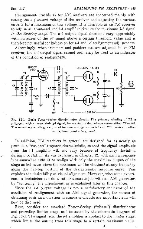
The A M generator method for realigning limiter-discriminator receivers, described above, is summarized in Table 13-1.
13-3. Ratio-Detector Realignment
The limiter stage is ordinarily omitted when the ratio detector is used, since the ratio detector does its own limiting.
Figure 13-2 shows the schematic diagram of a typical ratio-detector circuit. With this type, VTVM measurements for indication in realign-
T A B L E 13-1. A M GENERATOR METHOD FOR LIMITER-DISCRIMINATOR RECEIVERS
Connect Signal Generator
Dummy Antenna
Type of Signal
Set Signal-Generator
Frequency to Receiver Dial Set
Connect VTVM Adjust Adjust for
1. Antenna input terminals or mixer grid
Small mica capacitor
Unmodulated
Specified intermediate frequency
Any setting oscillator tuning-capacitor section shorted
Across limiter-grid resistor
I-f transformers Maximum V T V M readings and symmetry
2. Same as above Same as above
Same as above
Same as above Same as above Across either discrim. load resistor {R2 or RS in Fig. 13-1)
Discriminator-transformer primary circuit
Same as above
3. Same as above Same as above
Same as above
Same as above Same as above Across both load resistors point a to ground in Fig. 13-1
Discriminator-transformer secondary circuit
Zero d-c voltage
4. Same as above Same as above
Same as above
108 mc 108 mc Across limiter-grid resistor
Oscillator trimmer
Properly tuned signal and maximum V T V M reading
5. Same as above Same as above
Same as above
88 mc 88 mc Same as above Oscillator padder, if any, or bend coil turns
Same as above
6. Same as above Same as above
Same as above
108 mc 108 mc Same as above R-f and mixer trimmers
Maximum V T V M reading
7. Same as above Same as above
Same as above
88 mc 88mc Same as above R-f and mixer padders or bend coil turns
Same as above
NOTE: Repeat Steps 4, 5, 6, and 7 one or more times to ensure accuracy.
SEC. 13-3] REALIGNING FM RECEIVERS • 449
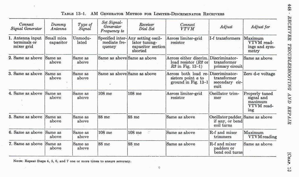
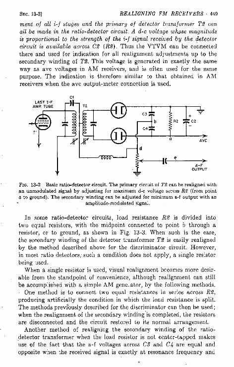
merit of all i-f stages and the primary of detector transformer T2 can all be made in the ratio-detector circuit. A d-c voltage whose magnitude is proportional to the strength of the i-f signal received by the detector circuit is available across C2 (R2). Thus the V T V M can be connected there and used for indication for all realignment adjustments up to the secondary winding of T2. This voltage is generated in exactly the same way as avc voltages in A M receivers, and is often used for the same purpose. The indication is therefore similar to that obtained in A M receivers when the avc output-meter connection is used.
FIG. 13-2 Basic ratio-detector circuit. The primary circuit of T2 can be realigned with an unmodulated signal by adjusting for maximum d-c voltage across R2 (from point a to ground). The secondary winding can be adjusted for minimum a-f output with an
amplitude-modulated signal.
In some ratio-detector circuits, load resistance R2 is divided into two equal resistors, with the midpoint connected to point b through a resistor, or to ground, as shown in Fig. 13-3. When such is the case, the secondary winding of the detector transformer T2 is easily realigned by the method described above for the discriminator circuit. However, in most ratio detectors; such a condition does not apply, a single resistor being used.
When a single resistor is used, visual realignment becomes more desirable from the standpoint of convenience, although realignment can still be accomplished with a simple A M generator, by the following methods.
One method is to connect two equal resistances in series across R2, producing artificially the condition in which the load resistance is split. The methods previously described for the discriminator can then be used; when the realignment of the secondary winding is completed, the resistors are disconnected and the circuit restored to its normal arrangement.
Another method of realigning the secondary winding of the ratio-detector transformer when the load resistor is not center-tapped makes use of the fact that the a-f voltages across CS and C4 are equal and opposite when the received signal is exactly at resonance frequency and

450 • RECEIVER TROUBLESHOOTING AND REPAIR [CHAP. 13
is amplitude-modulated by a suitable a-f signal. Because C3 and C4 are capacitors and not resistors, as in the Foster-Seeley discriminator, d-c voltages do not appear across them. However, the a-f signal does appear across each, being different in magnitude for all adjustments of the T2 secondary winding except for that adjustment producing exact resonance of that circuit, when they become equal. They are also opposite in polarity at all times, as are the d-c voltages across the load resistors in the discriminator. Thus it becomes apparent that, for an amplitude-
Fi}. 13-3 Variations of the ratio-detector circuit, showing how the VTVM may be connected to indicate condition of alignment of the transformer secondary winding.
In each case here, the adjustment is for minimum a-f output with an AM signal.
modulated signal, the a-f voltage at point b, with respect to the center of resistance R2, must be zero when the signal is exactly tuned in. Thus, the V T V M can be connected between the resistors added as described above, and point b and the a-f (a-c) voltage adjusted for zero. One advantage of this method is that the V T V M connection (to b) need not be in the detector circuit and can be made to d, e or any point in the a-f amplifier-signal circuit, including the loudspeaker circuit. Large signal amplitudes can thus be obtained, making for easy V T V M reading. However, it must be pointed out that the a-f voltage minimum is rather critical and the adjustment must be made with considerable care to avoid missing this minimum.
A number of slight variations are incorporated in the ratio detector circuits of modern receivers. The details of each are beyond the scope of this book, but the principles of operation are the same and the technician who understands the basic operation of the ratio detector will have no trouble in realignment. He will find that whenever special ratio-detector-circuit variations are used, the manufacturer's service data include detailed instructions as to procedure. To illustrate this, the following example is included.
Figure 13-4 shows the schematic diagram of the ratio-detector circuit
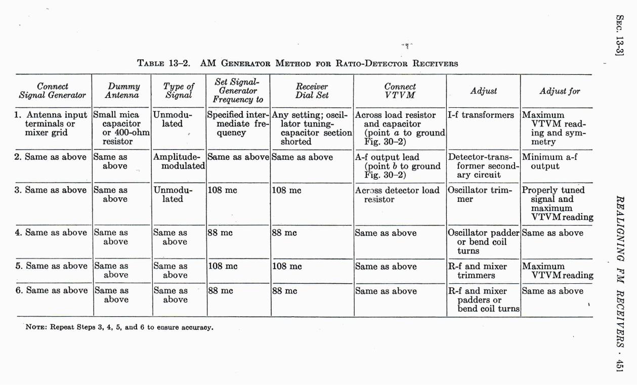
T A B L E 13-2. A M GENERATOR METHOD FOR RATIO-DETECTOR RECEIVERS
Connect Signal Generator
Dummy Antenna
Type of Signal
Set Signal-Generator
Frequency to Receiver Dial Set
Connect VTVM Adjust Adjust for
1. Antenna input terminals or mixer grid
Small mica capacitor or 400-ohm resistor
Unmodulated
Specified intermediate frequency
Any setting; oscillator tuning-capacitor section shorted
Across load resistor and capacitor (point a to ground Fig. 30-2)
I-f transformers Maximum V T V M reading and symmetry
2. Same as above Same as above
Amplitude-modulated
Same as above Same as above A-f output lead (point b to ground Fig. 30-2)
Detector-transformer secondary circuit
Minimum a-f output
3. Same as above Same as above
Unmodulated
108 mc 108 mc Across detector load resistor
Oscillator trimmer
Properly tuned signal and maximum V T V M reading
4. Same as above Same as above
Same as above
88 mc 88 mc Same as above Oscillator padder or bend coil turns
Same as above
5. Same as above Same as above
Same as above
108 mc 108 mc Same as above R-f and mixer trimmers
Maximum V T V M reading
6. Same as above Same as above
Same as above
88 mc 88 mc Same as above R-f and mixer padders or bend coil turns
Same as above
NOTE: Repeat Steps 3, 4, 5, and 6 to ensure accuracy.
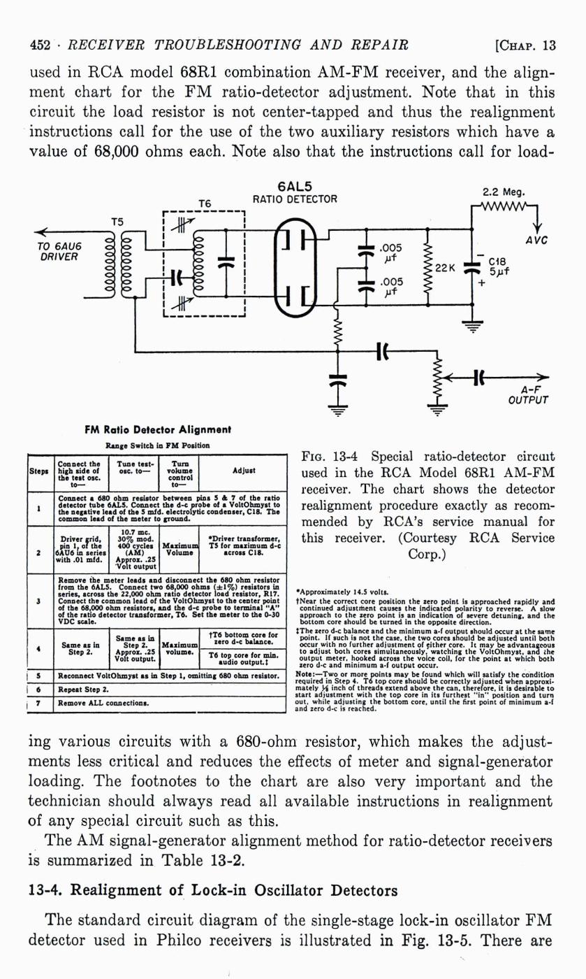
452 • RECEIVER TROUBLESHOOTING AND REPAIR [CHAP. 13
used in R C A model 68R1 combination A M - F M receiver, and the alignment chart for the F M ratio-detector adjustment. Note that in this circuit the load resistor is not center-tapped and thus the realignment instructions call for the use of the two auxiliary resistors which have a value of 68,000 ohms each. Note also that the instructions call for load-
6AL5 RATIO DETECTOR
2.2 Meg. r̂ vWvVvV̂ -l
FM Ratio Detector Alignment Range Switch in F M Position
Steps Connect the high side of the test osc.
to—
Tune test-osc. to—
Turn volume control t o -
Adjust
1 Connect a 680 ohm resistor between pins 5 & 7 of the ratio detector tube 6A.L5. Connect the d-c probe of a VoltOhmyst to the negative lead of the 5 mid. electrolytic condenser, C18. The common lead of the meter to ground.
2
Driver grid, pin 1, of the
6AU6 in series with .01 mfd.
10.7 mc. 30% mod. 400 cycles
(AM) Approx. .25 Volt output
Maximum Volume
'Driver transformer, TS for maximum d-c
across CIS.
3
Remove the meter leads and disconnect the 680 ohm resistor from the 6AL5. Connect two 68,000 ohms (±1%) resistors in series, scross the 22,000 ohm ratio detector load resistor, R17. Connect the common lead of the VoltOhmyst to the center point of the 68,000 ohm resistors, and the d-c probe to terminal " A " of the ratio detector transformer. T6. Set the meter to the 0-30 VDC scale.
4 Same as in Step 2.
Same as in Step 2.
Approz. .25 Volt output
Maximum volume.
TT6 bottom core for zero d-c balance.
4 Same as in Step 2.
Same as in Step 2.
Approz. .25 Volt output
Maximum volume. T6 top core for min.
audio output.;
Reconnect VoltOhmyst as in Step 1, omitting 680 ohm resistor.
6 Repeat Step 2.
7 Remove A L L connections.
A-F OUTPUT
FIG. 13-4 Special ratio-detector circuit used in the R C A Model 68R1 A M - F M receiver. The chart shows the detector realignment procedure exactly as recommended by RCA's service manual for this receiver. (Courtesy R C A Service
Corp.)
'Approximately 14.5 volts. tNear the correct core position the zero point is approached rapidly and continued adjustment causes the indicated polarity to reverse. A slow approach to the zero point is an indication of severe detuning, and the bottom core should be turned in the opposite direction.
{The zero d-c balance and the minimum a-f output should occur at the same point. If such is not the case, the two cores should be adjusted until both occur with no further adjustment of either core. It may be advantageous to adjust both cores simultaneously, watching the VoltOhmyst. ana the output meter, hooked across the voice coil, for the point at which both zero d-c and minimum a-f output occur.
Note:—Two or more points may be found which will satisfy the condition required in Step 4. T6 top core should be correctly adjusted when approximately H inch of threads extend above the can. therefore, it is desirable to start adjustment with the top core in its furthest " i n " position and turn out. while adjusting the bottom core, until the first point of minimum a-f and zero d-c is reached.
ing various circuits with a 680-ohm resistor, which makes the adjustments less critical and reduces the effects of meter and signal-generator loading. The footnotes to the chart are also very important and the technician should always read all available instructions in realignment of any special circuit such as this.
The A M signal-generator alignment method for ratio-detector receivers is summarized in Table 13-2.
13-4. Realignment of Lock-in Oscillator Detectors
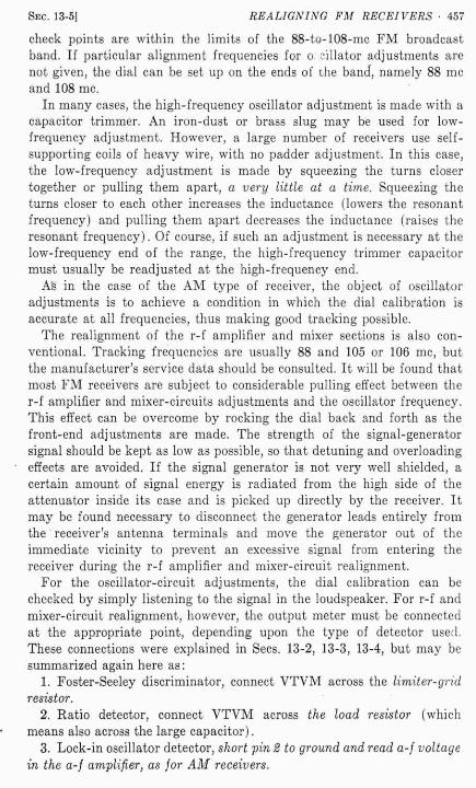
The standard circuit diagram of the single-stage lock-in oscillator F M detector used in Philco receivers is illustrated in Fig. 13-5. There are

SEC. 13-4] REALIGNING FM RECEIVERS • 453
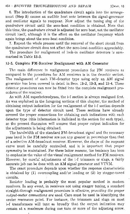
three main sections, the input circuit to which the i-f output signal is applied, the oscillator circuit, and the quadrature circuit. These are labeled in the figure. Realignment is accomplished by the following procedure:
1. Ground pin 2 of the FM1000 tube, thus short-circuiting the first grid to ground and disabling the oscillator.
2. This causes the detector to act as an A M detector. Feed an A M signal of exactly the intermediate frequency (modulated at 400 cps or other convenient audible frequency) into the i-f section and align the
F I G . 13-5 The standard circuit for the lock-in oscillator single-stage F M detector used in Philco receivers. The steps referred to correspond to the steps of the realignment
procedure in the text, with use of an unmodulated or A M signal-generator signal.
i-f section up through the last i-f transformer Tl, using the signal output of the a-f amplifier as indicator. This arrangement can also be used for realignment of the i-f and front-end sections later.
3. Remove the short circuit from pin 2 to ground and place a short circuit across the quadrature circuit, as shown in the figure for step 3.
4. Now adjust the oscillator trimmer capacitor until an audible beat note between the oscillator signal and the signal-generator signal from the i-f section is heard from the receiver's loudspeaker. Adjust the trimmer until the oscillator-signal zero beats the i-f signal. 1
5. Remove the short circuit from the quadrature circuit and lower the output voltage of the signal generator to the lowest value at which a usable signal can still be heard. This is very important and use of too strong a signal upsets the whole realignment job.
1 As the zero-beat point is approached, the audio beat note becomes lower in pitch (frequency) and disappears when the zero-beat point is reached. Further adjustment in the same direction causes the beat note to reappear with rising pitch, indicating the adjustment has gone too far; the trimmer is then turned in the other direction to again obtain the zero-beat condition.
INPUT CIRCUIT
S T E P 1 - Ground pin 2 ( Grid No.1)
S T E P 6 - Slug adjustment for zero beat
T1 LAST
I-F TRANSF.
454 • RECEIVER TROUBLESHOOTING AND REPAIR [CHAP. 13
6. The introduction of the quadrature circuit again into the arrangement (Step 5) causes an audible beat note between the signal-generator and oscillator signals to reappear. Now adjust the tuning slug of the quadrature circuit until the zero-beat condition is obtained. Note that this time, the quadrature circuit is adjusted for zero beat, not the oscillator circuit itself, although it is the effect on the oscillator frequency which again brings about the zero-beat condition.
7. Repeat the whole process until the removal of the short circuit from the quadrature circuit does not affect the zero-beat condition appreciably.
The procedure for realignment of lock-in oscillator detectors is summarized in Table 13-3.
13-5. Complete FM-Receiver Realignment with A M Generator
The main difference in realignment procedures for F M receivers as compared to the procedures for A M receivers is in the detector section. The realignment of each FM-detector type using only an A M signal generator has been covered in detail in Sees. 13-2, 13-3, and 13-4. These detector procedures can now be fitted into the complete realignment procedures of the receiver.
As with A M superheterodynes, the i-f section is always realigned first. As was explained in the foregoing sections of this chapter, the method of obtaining output indication for the realignment of the i-f section depends upon the type of detector circuit used. These sections have already covered the proper connections for obtaining such indications with each detector type (this information is italicized in the section for each type), so the present discussion will assume that proper output indication for the adjustments is being obtained.
The bandwidth of the standard FM-broadcast signal and the necessary pass band in the F M receiver are not any greater in percentage than that of a selective AM-broadcast receiver. However, the shape of the response curve must be carefully controlled, and it is important that proper symmetry be maintained. For these latter reasons, the tendency has been to emphasize the value of the visual realignment method for F M receivers. However, by careful adjustments of the i-f trimmers or slugs, a fairly accurate job can be done with an A M signal generator and V T V M .
The exact procedure depends upon whether the response characteristic is obtained by (1) overcoupling and/or loading or (2) by stagger-tuned circuits. i
Resistor loading is probably the most popular method in modern receivers. In any event, in receivers not using stagger tuning, a standard straight-through realignment procedure is effective, providing the proper output-meter connections are used. Care must be used in identifying the center resonance point. For instance, the trimmers and slugs on most i-f transformers will tune so broadly that the output indication may remain at a maximum during one turn or more of the adjusting screw.

T A B L E 13-3. A M GENERATOR METHOD FOR LOCK-IN OSCILLATOR-DETECTOR RECEIVERS
Connect Signal Generator
Dummy Antenna
Type of Signal
Set Signal-Generator
Frequency to Receiver Dial Set
Connect VTVM Adjust Adjust for
1. Antenna input terminals or mixer grid
Small mica capacitor or 400-ohni resistor
Amplitude-modulated
Specified intermediate frequency
Any setting oscillator tuning-capacitor section shorted
To a-f output with pin 2 of F M 1,000 tube shorted to ground
I-f transformers Maximum V T V M reading
2. Same as above Same as above
Unmodulated
Same as above Same as above Unshort pin 2, short quad circuit, listen to speaker output
Detector oscillator trimmer
Zero beat
3. Same as above Same as above
Same—keep minimum strength
Same as above Same as above Unshort quad circuit listen to speaker output
Detector quad circait
Zero beat
4. Antenna input terminals
Same as above
Amplitude-modulated
108 mc 108 mc Short pin 2 V T V M to a-f output
Oscillator trimmer
Properly tuned signal and maximum V T V M reading
5. Same as above Same as above
Same as above
88 mc 88 mc Same as above Oscillator padder or bend coil turns
Same as above
6. Same as above Same as above
Same as above
108 mc 108 mc Same as above R-f and mixer trimmers
Maximum V T V M reading
7. Same as above Same as above
!
Same as above
88 mc 88 mc Same as above R-f and mixer padders or bend coil turns
Same as above
NOTE: Repeat Step* 4, 5, 6, and 7.

456 • RECEIVER TROUBLESHOOTING AND REPAIR [CHAP. 13
In this case, the screw should be turned both ways until the adjustment in each direction that causes the first noticeable drop in signal output is found. The screw is then adjusted to a point midway between these two points.
If the i-f amplifier is of the stagger-tuned type, single coupling coils (impedance coupling) are nearly always used. Each tuned circuit must be adjusted at a different resonance frequency. The individual circuits of a stagger-tuned amplifier are generally sharper than those of the straight-through type, and are therefore more easily adjusted for the maximum-output condition.
As with the A M superheterodyne receiver, there is no point in feeding the i-f signal into the mixer or i-f stage grid circuit if it can be passed through the whole receiver from a connection to the antenna terminals. The same principles for injecting the i-f signal into the receiver apply here as were explained for A M receivers in Chapter 12, except that the effects of loading are much greater in the high-frequency i-f section of the F M receiver.
It is generally desirable to start at the detector circuit and realign toward the front end of the receiver, although this is not absolutely necessary.
For stagger-tuned receivers (which are seldom encountered) the generator is successively set at the different resonant frequencies, each coil being realigned at the specified frequency called for by the manufacturer. The individual resonant frequencies of stagger-tuned circuits must be obtained from an authoritative source. There is no way for the technician to "guess" or "estimate" these frequencies, since they were designated by the designer of the receiver.
For "straight-through" i-f sections, the realignment proceeds from stage to stage with the signal generator always set at the intermediate frequency and the adjustments made for maximum indications on the output meter, which must be properly connected in the detector circuit, as previously explained.
In other than stagger-tuned i-f sections, it is extremely important that the signal generator be kept adjusted to the same frequency for all detector and i-f amplifier realignment adjustments. Failure to maintain this condition will result in distortion and failure of the detector to produce a good a-f signal when the front end is properly tuned.
Except for the special output-meter connections for each detector type, as previously explained, and the care necessary in centering the response characteristic, the i-f amplifier realignment is the same as for A M receivers, as described in Chapter 12, and the technician should encounter little difficulty with it.
When the detector and i-f amplifier sections have been realigned, the oscillator circuit is next adjusted. Adjustment procedure is exactly the same as for A M receivers, except, of course, the low- and high-frequency
SEC. 13-5] REALIGNING FM RECEIVERS • 457
check ppints are within the limits of the 88-to-108-mc F M broadcast band. If particular alignment frequencies for o. dilator adjustments are not given, the dial can be set up on the ends of the band, namely 88 mc and 108 mc.
In many cases, the high-frequency oscillator adjustment is made with a capacitor trimmer. An iron-dust or brass slug may be used for low-frequency adjustment. However, a large number of receivers use self-supporting coils of heavy wire, with no padder adjustment. In this case, the low-frequency adjustment is made by squeezing the turns closer together or pulling them apart, a very little at a time. Squeezing the turns closer to each other increases the inductance (lowers the resonant frequency) and pulling them apart decreases the inductance (raises the resonant frequency). Of course, if such an adjustment is necessary at the low-frequency end of the range, the high-frequency trimmer capacitor must usually be readjusted at the high-frequency end.
As in the case of the A M type of receiver, the object of oscillator adjustments is to achieve a condition in which the dial calibration is accurate at all frequencies, thus making good tracking possible.
The realignment of the r-f amplifier and mixer sections is also conventional. Tracking frequencies are usually 88 and 105 or 106 mc, but the manufacturer's service data should be consulted. It will be found that most F M receivers are subject to considerable pulling effect between the r-f amplifier and mixer-circuits adjustments and the oscillator frequency. This effect can be overcome by rocking the dial back and forth as the front-end adjustments are made. The strength of the signal-generator signal should be kept as low as possible, so that detuning and overloading effects are avoided. If the signal generator is not very well shielded, a certain amount of signal energy is radiated from the high side of the attenuator inside its case and is picked up directly by the receiver. It may be found necessary to disconnect the generator leads entirely from the' receiver's antenna terminals and move the generator out of the immediate vicinity to prevent an excessive signal from entering the receiver during the r-f amplifier and mixer-circuit realignment.
For the oscillator-circuit adjustments, the dial calibration can be checked by simply listening to the signal in the loudspeaker. For r-f and mixer-circuit realignment, however, the output meter must be connected at the appropriate point, depending upon the type of detector used. These connections were explained in Sees. 13-2, 13-3, 13-4, but may be summarized again here as:
1. Foster-Seeley discriminator, connect V T V M across the limiter-grid resistor.
2. Ratio detector, connect V T V M across the load resistor (which means also across the large capacitor).
3. Lock-in oscillator detector, short pin 2 to ground and read a-f voltage in the a-f amplifier, as for AM receivers.
458 • RECEIVER TROUBLESHOOTING AND REPAIR [CHAP. 13
Up to this point, this chapter has covered the realignment of F M receivers by use of an A M signal generator and a V T V M . This method is somewhat slower than visual realignment, but allows the technician not owning a sweep generator and oscilloscope to realign the F M receivers which come to his bench. The more rapid and convenient visual method will now be discussed.
13-6. Principles and Advantages of Visual Realignment
Visual realignment provides a picture of the response characteristic of the receiver that the technician can observe while he makes the realignment adjustments. For this reason, great accuracy and convenience as well
v= VERTICAL OEFLECTION PLATES
H - HORIZONTAL DEFLECTION
PLATES
(B) / . N OSCILLOSCOPE SWEEP VOLTAGE ( A ) SYNCHRONIZED TO
GENERATOR FREQUENCY SWEEP
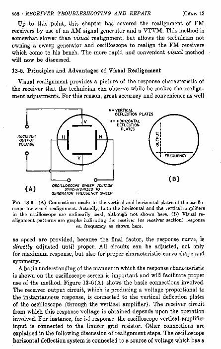
Fio. 13-6 (A) Connections made to the vertical and horizontal plates of the oscilloscope for visual realignment. Actually, both the horizontal and the vertical amplifiers in the oscilloscope are ordinarily used, although not shown here. (B) Visual realignment patterns are graphs indicating the receiver (or receiver section) response
vs. frequency as shown here.
as speed are provided, because the final factor, the response curve, is directly adjusted until proper. A l l circuits can be adjusted, not only for maximum response, but also for proper characteristic-curve shape and symmetry.
A-basic understanding of the manner in which the response characteristic is shown on the oscilloscope screen is important and will facilitate proper use of the method. Figure 13-6 (A) shows the basic connections involved. The receiver output circuit, which is producing a voltage proportional to the instantaneous response, is connected to the vertical deflection plates of the oscilloscope (through the vertical amplifier). The receiver circuit from which this response voltage is obtained depends upon the operation involved. For instance, for i-f response, the oscilloscope vertical-amplifier input is connected to the limiter grid resistor. Other connections are explained in the following discussion of realignment steps. The oscilloscope horizontal deflection system is connected to a source of voltage which has a
SEC. 13-6] REALIGNING FM RECEIVERS • 459
waveform frequency synchronized to the sweep action of the signal generator. Each time the signal-generator signal frequency is swept through its range, the oscilloscope horizontal sweep goes through a cycle (two cycles in some cases). Thus, each point along the horizontal axis of the oscilloscope corresponds to a particular frequency in the generator's sweep range.
A graph depicting the relation between receiver output voltage and frequency is developed on the oscilloscope screen, as shown in Fig. 13-6 (B).
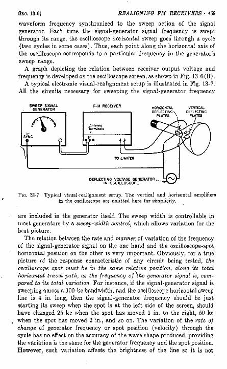
A typical electronic visual-realignment setup is illustrated in Fig. 13-7. Al l the circuits necessary for sweeping the signal-generator frequency
FIG. 13-7 Typical visual-realignment setup. The vertical and horizontal amplifiers in the oscilloscope are omitted here for simplicity.
are included in the generator itself. The sweep width is controllable in most generators by a sweep-width control, which allows variation for the best picture.
The relation between the rate and manner, of variation of the frequency of the signal-generator signal on the one hand and the oscilloscope-spot horizontal position on the other is very important. Obviously, for a true picture of the response characteristic of any circuit being tested,' the oscilloscope spot must be in the same relative position, along its total horizontal travel path, as the frequency of the generator signal is, compared to its total variation. For instance, if the signal-generator signal is sweeping across a 100-kc bandwidth, and the oscilloscope horizontal sweep line is 4 in. long, then the signal-generator frequency should be just starting its sweep when the spot is at the left side of the screen, should have changed 25 kc when the spot has moved 1 in., to the right, 50 kc when the spot has moved 2 in., and so on. The variation of the rate of change of generator frequency or spot position (velocity) through the cycle has no effect on the accuracy of the wave shape produced, providing the variation is the same for the generator frequency and the spot position. However, such variation affects the brightness of the line so it is not
460 • RECEIVER TROUBLESHOOTING AND REPAIR [CHAP. 13
constant across the pattern, being brightest where the spot velocity is the lowest.
Thus, it does not matter, as far as accuracy of response shape is concerned, whether a sine wave or sawtooth wave is used for signal frequency and oscilloscope-spot deviation, as long as both waves are the same. If they are different, "bunching" and "pulling apart" will occur in the pattern, and adjustment for symmetry is difficult.
Most sweep-signal generators designed for receiver servicing and in the price range of the service technician employ sine-wave sweep, obtained
H . 7 M C —
10.7 M O
9 .7 M C —
SINE WAVE SIGNAL GENERATOR
FREQUENCY VARIATION
L E F T S I D E O F S C R E E N .
SINE WAVE OSCILLOSCOPE SPOT POSITION VARIATION
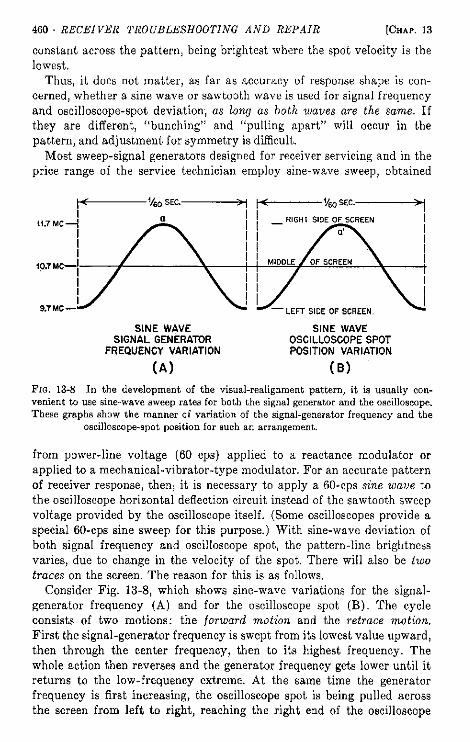
(A) (B) F I G . 13-8 In the development of the visual-realignment pattern, it is usually convenient to use sine-wave sweep rates for both the signal generator and the oscilloscope. These graphs show the manner of variation of the signal-generator frequency and the
oscilloscope-spot position for such an arrangement.
from power-line voltage (60 cps) applied to a reactance modulator or applied to a mechanical-vibrator-type modulator. For an accurate pattern of receiver response, thenj it is necessary to apply a 60-cps sine wave to the oscilloscope horizontal deflection circuit instead of the sawtooth sweep voltage provided by the oscilloscope itself. (Some oscilloscopes provide a special 60-cps sine sweep for this purpose.) With sine-wave deviation of both signal frequency and oscilloscope spot, the pattern-line brightness varies, due to change in the velocity of the spot. There will also be two traces on the screen. The reason for this is as follows.
Consider Fig. 13-8, which shows sine-wave variations for the signal-generator frequency (A) and for the oscilloscope spot (B). The cycle consists of two motions: the forward motion and the retrace motion. First the signal-generator frequency is swept from its lowest value upward, then through the center frequency, then to its highest frequency. The whole action then reverses and the generator frequency gets lower until it returns to the low-frequency extreme. At the same time the generator frequency is first increasing, the oscilloscope spot is being pulled across the screen from left to right, reaching the right end of the oscilloscope

SEC. 13-6] REALIGNING FM RECEIVERS • 461
trace at the same time the signal frequency stop's increasing, then sweeping back from right to left.
Thus, with this arrangement, one response curve is traced in the forward (left to right) trace and one in the retrace. If the resonant frequency of the i-f section of the receiver being tested is at the exact center of the sweep-frequency range of the generator, the two traces will coincide in the center; otherwise, there will be two traces, as in Fig. 13-9(B).
As is explained later in this chapter, a double trace similarly obtained is very useful in balancing discriminators and ratio detectors, by use of a "crisscross" pattern.
If both circuits are deflected by a sawtooth-shaped wave, accurate traces and the double image will result. However, the return trace will be much
(A) (B) F I G . 13-9 Typical response patterns used in the realignment of the i-f section of an F M receiver. (A) Proper response after realignment is completed; (B) response curves
resulting when the resonant frequency is a little off the frequency of the i-f signal.
less bright than the forward trace, since the oscilloscope spot moves so much more rapidly during the fast retrace, or "snap-back," portion of the waveform. But since both waves are linear with respect to time, the brightness of each trace will be constant over the limits of the trace itself. For an ideal condition in which both traces have the same brightness and this brightness is constant over- the entire range of each pattern, the signal-generator frequency variation must have a triangular waveform. That is, the frequency increase and decrease must both occur linearly and in the same time (each half of the cycle). The oscilloscope sweep voltage must of course have the same waveform. Since the usefulness of the visual-realignment method to the technician is in observation only of the shape of the response curve, and not the relative brightness of its parts, such refinements are not of particular importance, but should be understood.
To eliminate the retrace pattern, some sweep-signal generators are equipped with blanking circuits, providing a pulse signal which can be applied to the CR-tube grid or interrupting the generator signal during the retrace period. This arrangement not only eliminates the retrace pattern, but in the latter case also provides a horizontal base line, traced by the oscilloscope spot on its return from right to left, when it is now no longer deflected vertically.

462 • RECEIVER TROUBLESHOOTING AND REPAIR [CHAP. 13
When the desired response pattern has been obtained, adjustments can be made, in the appropriate section of the receiver, so as to shape that response to its proper configuration.
Although the visual response pattern shows the shape and symmetry of the characteristic, it gives no clue to its exact position in the frequency spectrum, which of course must be known for proper realignment. This information is provided by an auxiliary signal generator, called a marker generator. This device is simply a signal generator providing a steady, unmodulated signal within the sweep range being used. For instance, if the i-f response of an F M receiver is being viewed, the 10.7-mc point along the response characteristic is of special significance. The marker-generator signal is fed into the receiver, the leads from this generator connected in parallel with those from the sweep generator, or, if there is sufficient signal voltage, loosely coupled separately. The marker signal introduces an irregularity in the response curve, as shown in the pattern of Fig. 13-9. This irregularity is referred to as a "pip" and shows the symmetry of the response curve with respect to the 10.7-mc center frequency.
If the marker generator is variable, it can be adjusted to any desired frequency in the sweep range. Then the frequencies at which the characteristic falls off at the low and high extremes and other information can be determined. Marker signals are even more extensively useful in TV-receiver realignment, as explained in Chapter 14.
Another type of marking can be obtained from an absorption-type marker. This is simply a tuned circuit connected across the receiver input connections from the signal generator and resonated at the desired marking frequency. Each time the signal-generator frequency sweeps past the resonant frequency, the signal is short-circuited. Thus a small blank spot appears in the response curve at the marker frequency as illustrated in Fig. 14-3.
The connections for the vertical-plate amplifier leads of the oscilloscope must be made according to the type of detector used in the receiver to be realigned. Information about actual procedures is given in the next section.
13-7. Visual Realignment Procedure for Limiter-Discriminator Receivers
As with the A M method, visual realignment starts in the i-f and detector sections. Since the details vary with the type of detector employed, procedures are given for each type.
In the limiter-discriminator type of receiver, either the detector or the i-f amplifier can be realigned first, but it is very important that the marker frequencies be kept exact, so that errors in the coincidence of the resonant frequencies of the two sections do not creep in. Note, however, that because the complete response curve is being viewed, chances of error due to realignment of these sections at different frequencies are
SEC. 13-7] REALIGNING FM RECEIVERS • 463
not as great as for the A M generator method explained in the first part of this chapter.
As previously explained, deflection waveforms in the signal generatpr and the oscilloscope horizontal circuit must be the same. Since most sweep generators for servicing use sine-wave sweep, it is best to set the oscilloscope for sine-wave-deflection voltage, which in some cases is provided by the oscilloscope circuits themselves and is set by a selector knob on the front panel. Otherwise, an external deflection outlet may be provided on the oscilloscope panel, and the 60-cps deflection voltage from the signal generator used for horizontal deflection of the spot.
The oscilloscope vertical deflection leads are connected across the limiter-grid resistor. The i-f signal is injected into the receiver in the usual manner with the sweep width adjusted to about 200 or 300 kc. The signal generator is adjusted for the weakest usable signal and the oscilloscope horizontal- and vertical-gain controls adjusted for a reasonably sized screen pattern. Focus and brightness are adjusted to individual taste.
Usually the 60-cps sweep voltages for the signal generator and the oscilloscope are obtained from the power line, and are thus automatically synchronized. However, in cases in which the oscilloscope internal-sweep voltage is used, careful tuning of the fine frequency control on its panel may be necessary. Some signal generators are equipped with a phasing control which facilitates synchronization.
As previously explained, the response pattern is double, one trace for the forward sweep (left to right on oscilloscope screen) and the other trace for the return (see Fig. 13-8). When the sweep range of the signal is properly centered about the center frequency (correct intermediate frequency) and the resonant frequency of the circuit, being realigned, is equal to this center frequency, the two response patterns coincide and appear as a single pattern as in Fig. 13-9(A).
For best results in i-f realignment, center up the patterns by injecting the signal into the grid of the last i-f amplifier stage (before the limiter). Also inject a signal from a marker-signal generator (any stable signal generator with an unmodulated signal can be used) and adjust the marker signal to exactly the specified intermediate frequency. The center frequency of the signal generator and the trimmers on the i-f transformer following the last i-f stage (limiter input) are then adjusted simultaneously until the two patterns [Fig. 13-9(B)] coincide and are symmetrical about the marker pip, as shown in Fig. 13-9(A). T*he center frequency of the sweep generator is then kept constant at this setting. The i-f signal is injected one stage back toward the mixer; th*e adjustment now is simply for the point at which the two patterns meet in the center of the screen. This procedure is repeated for each stage in the i-f amplifier section.
As the adjustment of the circuit approaches resonance, the response
464 • RECEIVER TROUBLESHOOTING AND REPAIR [CHAP. 13
patterns not only move toward each other, but also increase in height, due to the increase in gain as the resonance condition is approached. The adjustment is therefore for maximum height and blending of the two traces into one. It is often necessary to reduce the output of the signal generator as resonance is approached to keep from overloading any of the amplifier stages and to keep the trace on the screen (the trace can also be adjusted, of course, by the height control on the scope).
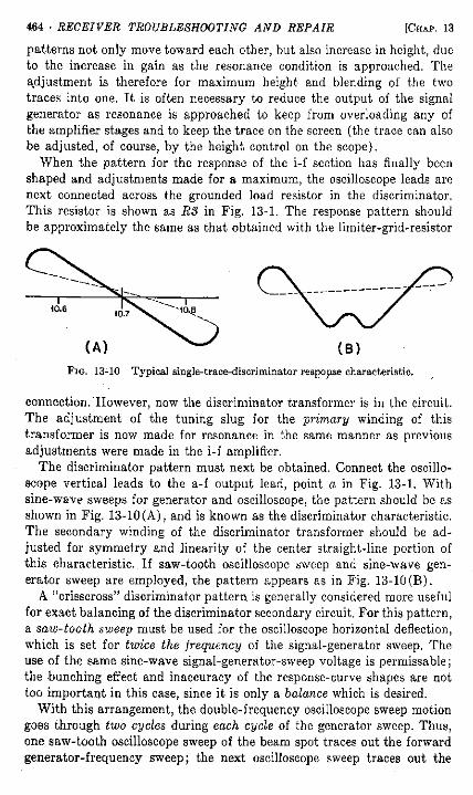
When the pattern for the response of the i-f section has finally been shaped and adjustments made for a maximum, the oscilloscope leads are next connected across the grounded load resistor in the discriminator. This resistor is shown as RS in Fig. 13-1. The response pattern should be approximately the same as that obtained with the limiter-grid-resistor
FIG. 13-10 Typical single-trace-discriminator response characteristic.
connection. However, now the discriminator transformer is in the circuit. The adjustment of the tuning slug for the -primary winding' of this transformer is now made for resonance in the same manner as previous adjustments were made in the i-f amplifier.
The discriminator pattern must next be obtained. Connect the oscilloscope vertical leads to the a-f output lead, point a in Fig. 13-1. With sine-wave sweeps for generator and oscilloscope, the pattern should be as shown in Fig. 13-10(A), and is known as the discriminator characteristic. The secondary winding of the discriminator transformer should be adjusted for symmetry and linearity of the center straight-line portion of this characteristic. If saw-tooth oscilloscope sweep and sine-wave generator sweep are employed, the pattern appears as in Fig. 13-10 (B).
A "crisscross" discriminator pattern is generally considered more useful for exact balancing of the discriminator secondary circuit. For this pattern, a saw-tooth sweep must be used for the oscilloscope horizontal deflection, which is set for twice the frequency of the signal-generator sweep. The use of the same sine-wave signal-generator-sweep voltage is permissable; the bunching effect and inaccuracy of the response-curve shapes are not too important in this case, since it is only a balance which is desired.
With this arrangement, the double-frequency oscilloscope sweep motion goes through two cycles during each cycle of the generator sweep. Thus, one saw-tooth oscilloscope sweep of the beam spot traces out the forward generator-frequency sweep; the next oscilloscope sweep traces out the
S E C . 13-7] REALIGNING FM RECEIVERS • 465
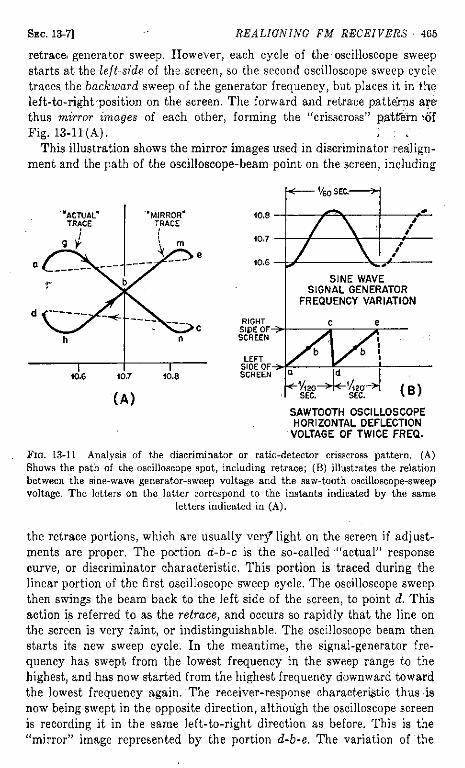
retrace generator sweep. However, each cycle of the oscilloscope sweep starts at the left side of the screen, so the second oscilloscope sweep, cycle traces the backward sweep of the generator frequency, but places it in the left-to-right, position on the screen. The forward and retrace .patterns are thus mirror images of each other, forming the "crisscross" pattern sdf Fig. 13-11 (A). • ] ... «:
This illustration shows the mirror images used in discriminator realignment and the path of the oscilloscope-beam point on the screen, including
•< Vfeo SEC >
SAWTOOTH OSCILLOSCOPE HORIZONTAL DEFLECTION
VOLTAGE OF TWICE FREQ.
F I G . 13-11 Analysis of the discriminator or ratio-detector crisscross pattern. (A) Shows the path of the oscilloscope spot, including retrace; (B) illustrates the relation between the sine-wave generator-sweep voltage and the saw-tooth oscilloscope-sweep voltage. The letters on the latter correspond to the instants indicated by the same
letters indicated in (A).
the retrace portions, which are usually very* light on the screen if adjustments are proper. The portion a-b-c is the so-called "actual" response curve, or discriminator characteristic. This portion is traced during the linear portion of the first oscilloscope sweep cycle. The oscilloscope sweep then swings the beam back to the left side of the screen, to point d. This action is referred to as the retrace, and occurs so rapidly that the line on the screen is very faint, or indistinguishable. The oscilloscope beam then starts its new sweep cycle. In the meantime, the signal-generator frequency has swept from the lowest frequency in the sweep range to the highest, and has now started from the highest frequency downward toward the lowest frequency again. The receiver-response characteristic thus is now being swept in the opposite direction, although the oscilloscope screen is recording it in the same left-to-right direction as before. This is the "mirror" image represented by the portion d-b-e. The variation of the

466 • RECEIVER TROUBLESHOOTING AND REPAIR [CHAP. 13
signal-generator frequency with time, and the variation of the horizontal deflection voltage in the oscilloscope, both plotted on the same time base, are shown in Fig. 13-11 (B). The letters on the saw-tooth line correspond to positions along the time base indicated by the same letters in Fig. 13-11 (A).
When the crisscross pattern of this type is obtained, the primary circuit of the discriminator transformer is adjusted for maximum distance between peaks g and h, and between m and n.
The secondary circuit of the discriminator transformer is adjusted for best symmetry of the whole pattern, but especially for the crossover point (b) to be in the center of the pattern. Figure 13-12 shows two incorrect patterns [(A) and (B)] and a properly-centered one (C).
( A ) ( B ) ( C )
FIG. 13-12 Three crisscross patterns, showing (A) and (B) incorrect balance and (C) proper alignment.
When the discriminator has been properly realigned for the conditions described above, the technician may proceed to the front-end portion of the receiver. These adjustments are made with the limiter-grid resistor as the connecting point for the oscilloscope leads, as in the realignment of the i-f section previously described. All front-end adjustments are then made for maximum response-curve height.
The oscillator is set successively at two points in the tuning range of the dial, exactly as in AM-broadcast superheterodyne receivers, except that the frequency values are somewhere near 88 and 108 mc respectively. Trimmer adjustments are nearly always provided, except in the case of "guillotine" and some resonant-line types of tuners, in which a screwdriver or nut-wrench adjustment varies the relative mechanical motion in each tuned circuit for tracking. In some receivers, capacitive padders for low-frequency adjustment are provided; in others, an iron-dust or brass slug is provided with an adjusting thread. If the core is iron, it increases the inductance and lowers the resonant frequency as it is inserted into the coil; if it is brass, the effect is opposite.
Many F M receivers include no padder for the oscillator circuit. In this event, the manufacturer usually recommends that, if padding at the low-frequency end of the tuning range is necessary to make the dial read correctly, the turns of the self-supporting oscillator coil (if such is used) should be compressed (to increase inductance) or pulled apart (to decrease inductance). Care should be used in this operation, since only very slight adjustments are usually necessary and it may become very difficult
SEC. 13-8] REALIGNING FM RECEIVERS • 467
to return to the proper adjustment if the wire is bent too much. In the "Pilotuner" F M converter, the oscillator padding is accomplished by a screw and washer which press against one end of the coil, allowing the coil to be compressed or released as the screw is turned.
As with A M receivers, the objective of the oscillator frequency adjustments is to make the receiver's dial read correctly as calibrated, since good tracking is then most easily obtained. It is also important that the mechanical operation of the dial be checked, and that the capacitor or other tuning device and the dial be properly coupled.
When the oscillator has been properly adjusted, the r-f amplifier realignment follows. This adjustment is quite conventional, with the high- and low-realignment frequencies ordinarily 106 and 88 mc respectively. As with the oscillator circuit, it may be necessary to adjust at the low frequency by bending the coil turns slightly together or apart. The hands should be removed completely each time an adjustment is checked, since body effects can make the indications completely false.
Ratio-Detector Receivers. The realignment procedures for this type are the same as for the limiter-discriminator type discussed above, except that the oscilloscope leads are connected differently. For instance, the complete i-f amplifier section can be realigned by connecting the oscilloscope in the detector circuit, as is now explained in the following section.
The visual-alignment procedure for limiter-discriminator receivers and other types is summarized in Table 13-4.
13-8. Visual Realignment of Ratio-Detector Receivers
The realignment procedure for a ratio detector differs from that for a discriminator only in the change of oscilloscope connections, and the fact that adjustments are not complicated by the presence of a separate limiter circuit.
Refer to Fig. 13-2 for the following discussion. It will be remembered that the voltage across the load resistor R2 and capacitor C2 is proportional to the strength of the received i-f (and thus r-f) signal carrier. Accordingly, this voltage does not vary as the signal-generator signal changes in frequency over the normal sweep range. The capacitor maintains an even voltage, which provides the limiting effect of the ratio detector. Thus this voltage cannot be used for visual realignment of the i-f amplifier stages.
However, it has been pointed out that the instantaneous voltage across either CS or C4 varies as the i-f carrier is frequency-modulated. Thus visual realignment patterns can be obtained by connecting the oscilloscope leads from point b to ground. The same crisscross pattern of Fig. 13-11 (A) is thus obtained. Since there is no limiter stage preceding the detector in this case, the i-f amplifier, if it is of the "single-peaked" response type, can be realigned from this position of the oscilloscope leads. The crisscross pattern is kept under observation and the i-f amplifier transformers
468 • naCElVER TROUBLESHOOTING AND REPAIR [CHAP. 13
and the primary of the detector transformer are adjusted for maximum peak-to^peak height. The secondary winding of the detector-transformer winding is then adjusted for symmetry, as in the case of the discriminator.
Some manufacturers recommend disconnecting the load capacitor C2 during realignment of the i-f section. This causes the detector to act as an A ; M detector, and the oscilloscope leads are connected to point a and ground, after C2 has been disconnected. It is considered desirable under such circumstances to connect a 3-v battery in place of C2 so as to simulate the d-c voltage developed by an average signal, without allowing any of the limiting effect of the capacitor. It is very doubtful whether there are any advantages to this method over simply connecting the oscilloscope leads to the audio-output point 6 and ground, where no modification of the circuit is required.
Once the ratio-detector circuit has been realigned for symmetry and i-f response, the technician can proceed to the front-end adjustments. The V T V M is connected from point a to ground and the meter method of adjustment employed, or the crisscross pattern can be used for indication and the adjustments made for maximum peak-to-peak separation.
The procedure for realignment of ratio-detector receivers by the visual method is summarized in Table 13-4.
13-9. Visual Realignment of Lock-in Oscillator-Detector Receivers
The visual realignment of this type of receiver is quite simple. The oscilloscope vertical leads are connected to the a-f output terminals (point a and ground in Fig. 13-5) or to any signal point in the a-f amplifier, such as the primary or secondary windings of the output transformer.
The i-f signal is then injected into the i-f amplifier in the usual manner. The oscillator grid, pin 2, of the FM1000 tube is then grounded to the chassis; causing the section to act as an A M detector. (The intermediate frequency in these receivers is generally 9.1 mc.)
With this setup, the regular i-f response curves can be obtained on the oscilloscope screen, and the i-f section realigned. ! After the i-f section has been realigned, the short circuit is removed
from pin 2 and ground, and the quadrature circuit is short-circuited exactly as in the A M generator realignment explained earlier in this chapter. The oscillator signal is then zero-beat with the i-f signal in the same manner as in the A M procedure.
•When the oscillator has been set for zero beat, the short circuit is removed from the. quadrature circuit and the complete detector response observed on the oscilloscope.
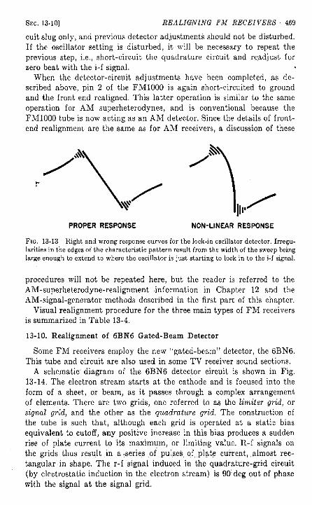
.This-complete response-is adjusted: by: manipulation of the slug adjustment on the quadrature circuit. The adjustment is made for linear response, or as close to it as possible. Figure 13-13 illustrates the proper pattern to look for and also gives an example of improper response. This last adjustment should be made by manipulation of the quadrature-cir-
SEC. 13-10] REALIGNING FM RECEIVERS • 469
cuit slug only, and previous detector adjustments should not be disturbed. If the oscillator setting is disturbed, it will be necessary to repeat the previous step, i.e., short-circuit the quadrature circuit and readjust for zero beat with the i-f signal.
When the detector-circuit adjustments have been completed, as described above, pin 2 of the FM1000 is again short-circuited to ground and the front end realigned. This latter operation is similar to the same operation for A M superheterodynes, and is conventional because the FM1000 tube is now acting as an A M detector. Since the details of front-end realignment are the same as for A M receivers, a discussion of these
FIG. 13-13 Right and wrong response curves for the lock-in oscillator detector. Irregularities in the edges of the characteristic pattern result from the width of the sweep being large enough to extend to where the oscillator is just starting to lock in to the i-f signal.
procedures will not be repeated here, but the reader is referred to the AM-superheterodyne-realignment information in Chapter 12 and the AM-signal-generator methods described in the first part of this chapter.
Visual realignment procedure for the three main types of F M receivers is summarized in Table 13-4.
13-10. Realignment of 6BN6 Gated-Beam Detector
Some F M receivers employ the new "gated-beam" detector, the 6BN6. This tube and circuit are also used in some TV receiver sound sections.
A schematic' diagram of the 6BN6 detector circuit is shown in Fig. 13-14. The electron stream starts at the cathode and is focused into the form of a sheet, or beam, as it passes through a complex arrangement of elements. There are two grids, one referred to as the limiter grid, or signal grid, and the other as the quadrature grid. The construction of the tube is such that, although each grid is operated at a static bias equivalent to cutoff, any positive increase in this bias produces a sudden rise of plate current to its maximum, or limiting value. R-f signals on the grids thus result in a series of pulses of plate current, almost rectangular in shape. The r-f signal induced in the quadrature-grid circuit (by electrostatic induction in the electron stream) is 90 deg out of phase with the signal at the signal grid.
PROPER RESPONSE NON-LINEAR RESPONSE
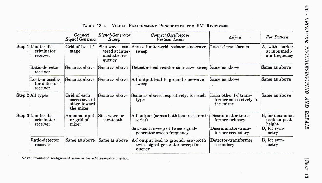
T A B L E 13-4. VISUAL REALIGNMENT PROCEDURES FOR F M RECEIVERS
Connect Signal Generator
Signal-Generator Sweep
Connect Oscilloscope Vertical Leads Adjust For Pattern
Step 1 Limiter-discriminator receiver
Grid of last i-f stage
Sine wave, centered at intermediate frequency
Across limiter-grid resistor sine-wave sweep
Last i-f transformer A, with marker at intermediate frequency
Ratio-detector receiver
Same as above Same as above Detector-load resistor sine-wave sweep Same as above Same as above
Lock-in oscillator-detector receiver
Same as above Same as above A-f output lead to ground sine-wave sweep
Same as above Same as above
Step 2 All types Grid of each successive i-f stage toward the mixer
Same as above Same as above, respectively, for each type
Each other I-f transformer successively to the mixer
Same as above
Step 3 Limiter-discriminator receiver
Antenna input or grid of mixer
Sine wave or saw-tooth
A-f output (across both load resistors in series)
Saw-tooth sweep of twice signal-generator sweep frequency
Discriminator-transformer primary
Discriminator-transformer secondary
B, for maximum peak-to-peak height
B, for symmetry
Ratio-detector receiver
Same as above Same as above A-f output lead to ground, saw-tooth twice signal-generator sweep frequency
Detector-transformer secondary
B, for symmetry
NOTE: Front-end realignment same as for A M generator method. 4

SEC. 13-10] REALIGNING FM RECEIVERS • 471
In the plate circuit, the pulses from the signal and quadrature grids are integrated so that only the relatively slow a-f variations can remain. The instantaneous integrated plate-current value depends upon the relative phase difference between the two sets of pulses. Since this phase difference depends upon the instantaneous frequency of the i-f signal received at the signal grid, the plate-current amplitude reflects the fre-
2 0 0 Ohms
FIG. 13-14 The element-arrangement and the circuit connections for the 6 B N 6 gated-beam detector for F M reception. The limiter grid is also referred to as the "signal grid."
quency variations (modulation) in the i-f signal. The plate-current variations appear as a-f voltage across the 68,000-ohm resistor in the plate circuit. Demodulation of the "FM signal has thus been completed.2
In receivers employing this detector, indication for realignment of the i-f amplifier stages can be obtained only by measurement of the r-f voltage at the signal (limiter) grid of the 6BN6. Thus the meter used must have good r-f response in the frequency range, or it must be provided with a suitable r-f probe. The steps in the realignment of the i-f and detector sections are as follows:
1. Adjust i-f transformers for maximum r-f voltage at the signal (limiter) grid of the detector.
2. Tune in an F M station for maximum deflection of the meter indicating r-f at the signal grid.
3. Adjust the quadrature-circuit coil for best sound reception. 4. Tune in a very weak signal, or remove the antenna and couple it 2 Further details about this detector are given in A. A. Ghirardi and J. R. Johnson,
Radio and Television Receiver Circuitry and Operation, Rinehart Books, Inc., New York, 1951. 11
472 • RECEIVER TROUBLESHOOTING AND REPAIR ICHAP. 13
very loosely by placing the leadin wire somewhere in the vicinity of the receiver input, so that a signal is received accompanied by a large amount of random noise (rushing or hissing noise).
5. Adjust the 200-ohm control in the cathode circuit for best signal-to-noise ratio, i.e., until the relative noise level is a minimum. If considerable adjustment is necessary, the technician may need to loosen antenna coupling to keep the noise always audible so changes in its level are discernible. Of course, a signal generator could be used, and the attenuator controls adjusted for proper level.
13-11. Prevalence of Combination A M - F M Receivers
A great majority of the F M receivers serviced by the technician will be of the combination A M - F M type, which use combination single transformers and combined separate transformers in their i-f sections of these receivers.
From the standpoint of realignment, the principal problems involved are identification of the proper portions of the combination transformers so that the realignment adjustments will be made at the proper locations. The technician will find it well worth his while to sketch a simple layout diagram of the top of the chassis, showing where each adjustment is located and what its purpose is, if such a diagram is not already available in the manufacturer's service data. Pencil markings on the chassis and the transformer cans do no harm and can be tremendously helpful. If the adjustments are not all easily identifiable, the A M i-f adjustments may be tampered with during an attempt to find the F M i-f adjustments and vice versa. Thus a whole realignment step may have to be repeated.
In most combination receivers, the manufacturer recommends that the F M i-f adjustments be made first, since their relative adjustment affects the A M section.
In certain receivers featuring A M , F M , and TV reception, the F M operation involves use of part of the TV sound section, whose i-f section is common with the F M i-f section.
S U M M A R Y
The realignment of FM receivers is basically the same as the realignment of A M superheterodyne receivers and differs therefrom mainly in the handling of the detector sections.
Although the visual-realignment method is more rapid and sometimes more accurate than the A M signal generator method, the latter is quite satisfactory for shops in which a sweep generator and oscilloscope are not available.
The special realignment problems in FM receivers have to do with locating the proper connections for the VTVM (in the meter method) or the oscilloscope (in the visual method) for each of the three types of detectors generally in use.
SUMMARY] REALIGNING FM RECEIVERS • 473
Indication must be obtained, first, of the strength of the i-f signal delivered to the detector, for i-f amplifier adjustments, and second, of. detector balance and/or linearity.
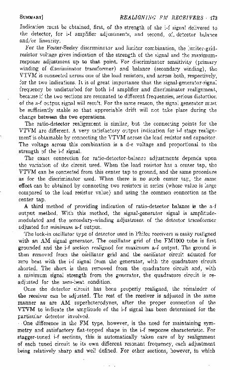
For the Foster-Seeley discriminator and limiter combination, the limiter-grid-resistor voltage gives indication of the strength of the signal and the maximum-response adjustment up to that point. For discriminator sensitivity (primary winding of discriminator transformer) and balance (secondary winding), the VTVM is connected across one of the load resistors, and across both, respectively, for the two indications. It is of great importance that the signal-generator-signal frequency be undisturbed for both i-f amplifier and discriminator realignment, because, if the two sections are resonated to different frequencies, serious distortion of the a-f output signal will result. For the same reason, the signal generator must be sufficiently stable so that appreciable drift will not take place during the change between the two operations.
The ratio-detector realignment is similar, but the connecting points for the VTVM are different. A very satisfactory output indication for i-f stage realignment" is obtainable by connecting the VTVM across the load resistor and capacitor. The voltage across this combination is a d-c voltage and proportional to the strength of the i-f signal.
The exact connection for ratio-detector-balance adjustments depends upon the variation of the circuit used. When the load resistor has a center tap, the VTVM can be connected from this center tap to ground, and the same procedure as for the discriminator used. When there is no such center tap, the same effect can be obtained by connecting two resistors in series (whose value is large compared to the load resistor value) and using the common connection as the center tap.
A third method of providing indication of ratio-detector balance is the a-f output method. With this method, the signal-generator signal is amplitude-modulated and the secondary-winding adjustment of the detector transformer adjusted for minimum a-f output.
The lock-in oscillator type of detector used in Philco receivers is easily realigned with an A M signal generator. The oscillator grid of the FM1000 tube is first grounded and the i-f section realigned for maximum a-f output. The ground is then removed from the oscillator grid and the oscillator circuit adusted for zero beat with the i-f signal from the generator, with the quadrature circuit shorted. The short is then removed from the quadrature circuit and, with a minimum signal strength from the generator, the quadrature circuit is readjusted for the zero-beat condition.
Once the detector circuit has been properly realigned, the remainder of the receiver can be adjusted. The rest of the receiver is adjusted in the same manner as are A M superheterodynes, after the proper connection of the V T V M to indicate the amplitude of the i-f signal has been determined for the particular detector involved.
One difference in the F M type, however, is the need for maintaining symmetry and satisfactory flat-topped shape in the i-f response characteristic. For stagger-tuned i-f sections, this is automatically taken care of by realignment of each tuned circuit to its own different resonant frequency, each adjustment being relatively sharp and well denned. For other sections, however, in which
474 • RECEIVER TROUBLESHOOTING AND REPAIR [CHAP. 13
overcoupling and loading are used, the broadness of the response may make it difficult to obtain a definite maximum-output indication. In this case, the trimmers or slugs should be manipulated until the signal drop-off on each side is indicated, and then carefully centered between the drop-off points.
Another special feature in many F M receivers is the use of self-supporting air-wound coils. It is often recommended by the manufacturer that padding at the low-frequency end of the tuning range be accomplished by bending the turns closer or farther apart.
Visual realignment has the advantage that the complete response curve of the receiver (or one section of it) can be observed at all times during the realignment procedures, thus allowing adjustments to be made more accurately and rapidly.
Visual patterns are obtained by use of a sweepTsignal generator and an oscilloscope for indication. As the sweep-signal-generator frequency moves through the sweep range, it is synchronized with the motion of the beam spot of the oscilloscope as it moves across the cathode-ray-tube screen. At the same time, the vertical deflection of the beam spot is proportional to the response of the receiver, thus causing the response characteristic to be traced out.
Best results in obtaining a visual pattern are obtained by use of similar sweep-voltage waveforms in both the signal generator and the oscilloscope horizontal circuit. Many signal generators sweep according to a sine-wave form; others use a saw-tooth-sweep voltage, or provide for both.
The connections for the oscilloscope for each portion of the realignment procedure are the same as for the corresponding operations with the VTVM, except for the realignment of the i-f section in the ratio-detector receiver. In this case, the oscilloscope is connected to the a-f output lead rather than to the load resistor.
In realignment of the discriminator and ratio-detector circuits, the crisscross type of pattern is most useful. This pattern is obtained by using an oscilloscope sweep frequency which is twice the signal-generator sweep frequency. Adjustment of the primary of the detector transformer for maximum peak-to-peak spacing and the secondary for center crossover location is possible with this pattern.
The visual realignment of the lock-in oscillator detector consists of two main operations. First, the oscillator grid of the F M 1 0 0 0 tube is grounded and the i-f transformers up to the detector are adjusted with the oscilloscope connected to the a-f output lead of the detector or to any signal point in the a-f amplifier.
The zero-beat condition with the quadrature circuit shorted is then obtained as in A M generator realignment. The short is then removed from the quadrature circuit and, with the oscilloscope leads connected to the a-f output, the response pattern is adjusted for best linearity with a minimum usable signal input.
Many of the F M receivers encountered by the technician will be the combination A M - F M type. The combination arrangement does not affect the procedures described above, except that care must be used in making proper identification of the F M and A M portions of the receiver, and most receivers are designed so that the F M portion of the i-f section should be realigned before the AM portion.

R E V I E W QUESTIONS] REALIGNING FM RECEIVERS • 475
R E V I E W QUESTIONS
13-1. What circuit section of the F M superheterodyne receiver is handled differently in realignment than the same section in the AM superheterodyne receiver?
13-2. What important action in the FM-receiver circuit makes for most of the differences in realignment procedure from the A M superheterodyne receiver?
13-3. Where should the VTVM leads be connected in a Foster-Seeley discriminator circuit to obtain output indication for realignment of the i-f amplifier section ?
' 13-4. What VTVM lead connections should be used for balancing the Foster-Seeley discriminator?
13-5. With what VTVM connection is the primary winding of the discriminator transformer best realigned?
13-6. What important condition is required concerning the frequency of the signal-generator signal during realignment of the i-f and detector sections?
13-7. Explain your answer to Q. 13-6. 13-8. What connection of the VTVM leads in the ratio detector gives a d-c
voltage indicative of the strength of the i-f signal from the i-f amplifier? 13-9. Explain how a ratio detector can be balanced by use of an amplitude-
modulated signal from the signal generator and an a-c VTVM. 13-10. Why do manufacturers sometimes recommend connection of a resistor
across a tuned circuit during realignment? 13-11. What connection is made in the lock-in oscillator detector to transform
it into an A M detector for i-f amplifier realignment? 13-12. What requirement is there with respect to the strength of the applied
generator signal during lock-in oscillator realignment? Why is this requirement necessary ?
13-13. What important information, not'necessary for overcoupled and loaded types, is necessary for the proper realignment of stagger-tuned i-f amplifier sections ?
13-14. In some receivers which are not equipped with low-frequency capacitor or slug padders, what method can be used for low-frequency padding of the oscillator ?
13-15. What are'the variables represented by the horizontal and the vertical directions in the graph swept out on the oscilloscope screen in visual realignment ?
13-16. What is the purpose of a marker generator in connection with visual realignment? When properly used, what is its effect on the response-characteristic picture ?
13-17. When a crisscross pattern is used for discriminator realignment, what characteristics of the pattern can be used (a) for discriminator-transformer primary and (b) discriminator-transformer secondary adjustments?
13-18. What precautions are important in the realignment of combination AM-FM receivers?