real time support and energy efficiency in wireless sensor networks238368/... · ·...
TRANSCRIPT
Technical report, IDE0805, January 2008
REAL-TIME SUPPORT AND ENERGY EFFICIENCY IN
WIRELESS SENSOR NETWORKS
Master Thesis in Computer System Engineering
Mahmood Ali and Sai Kumar Ravula
School of Information Science, Computer and Electrical Engineering
Halmstad University

Real Time Support and Energy Efficiency in WSN
ii

Real Time Support and Energy Efficiency in WSN
iii
REAL-TIME SUPPORT AND ENERGY EFFICIENCY IN
WIRELESS SENSOR NETWORKS
Master’s thesis in Computer System Engineering
School of Information Science, Computer and Electrical Engineering Halmstad University
Box 823, S-301 18 Halmstad, Sweden
January 2008

Real Time Support and Energy Efficiency in WSN
iv

Real Time Support and Energy Efficiency in WSN
v
Preface We would like to thank our supervisors Magnus Jonsson and Annette Böhm for giving us an opportunity to work under their supervision and guidance through out the Master’s thesis. Their valuable suggestions and ideas have given us great scope and flexibility to work in the best possible way to achieve our goals in this project. We would also like to thank our friends and families for their moral support during our thesis work. Mahmood Ali & Sai Kumar Ravula Halmstad University 2008

Real Time Support and Energy Efficiency in WSN
vi

Real Time Support and Energy Efficiency in WSN
vii
Abstract Wireless sensors nodes are made up of small electronic devices which are capable of sensing, computing and transmitting data from harsh physical environments like a surveillance field. These sensor nodes majorly depend on batteries for energy, which get depleted at a faster rate because of the computation and communication operations they have to perform. Communication protocols can be designed to make efficient utilization of energy resources of a sensor node and to obtain real time functionality. A set of previously reported routing and MAC (Medium Access Control) layer protocols has abilities to achieve energy efficiency and supports real-time functionality. A detailed study of these protocols has been carried out and comparison tables give an overview of the protocol’s performance on some factors like latency, scalability and energy awareness. Conclusions have been drawn using the comparison table parameters of how the protocol performs when utilized for a surveillance application and what kind of tradeoff they show. The conclusions and tabular information drawn here are from our theoretical analysis of protocols referred from journals; there is no simulation work done in this thesis.

Real Time Support and Energy Efficiency in WSN
viii

Real Time Support and Energy Efficiency in WSN
9
Table of Content 1. Introduction ...................................................................................................11
2. Problem Statement ........................................................................................13 3.1.1 Flat Routing............................................................................................................. 17 3.1.2 Hierarchical Routing............................................................................................... 17 3.1.3 Location-based Routing .......................................................................................... 17
3.2 Protocol Operation Based Routing Protocols............................................................ 18 3.2.1 Multi path-based ..................................................................................................... 18 3.2.2 Query-based ............................................................................................................ 18 3.2.3 Negotiation-based ................................................................................................... 18 3.2.4 Quality of Service (QoS)-based............................................................................... 19 3.2.5 Coherent-based ....................................................................................................... 19
3.3 Additional Classifications ............................................................................................ 19
4. Detailed Study of Routing Protocols ...........................................................21 4.1 LEACH (Low Energy Adaptive Clustering Hierarchical) ....................................... 21 4.2 PEGASIS (Power Efficient Gathering in Sensor Information Systems) ................ 24 4.3 SPIN (Sensor Protocol for Information via. Negotiation) ........................................ 27 4.4 GEAR (Geographic and Energy Aware Routing)..................................................... 31 4.5 GAF (Geographic Adaptive Fidelity) ......................................................................... 35 4.6 MECN (Minimum Energy Communication Network) ............................................. 38 4.7 SAR (Sequential Assignment Routing) ...................................................................... 40 4.8 SPEED Routing Protocol............................................................................................. 42
5. Comparison of Routing Protocols................................................................45
6. MAC (Medium Access Control)...................................................................49 6.1 Multiple Access Schemes ............................................................................................. 49
6.1.1 TDMA...................................................................................................................... 49 6.1.2 FDMA...................................................................................................................... 49 6.1.3 CDMA...................................................................................................................... 49
7. Carrier Sense Multiple Access (CSMA)......................................................49
8. Detailed Studies of MAC Protocols .............................................................51
8.1 Sensor-MAC (SMAC) Protocol................................................................................... 51 8.2 Timeout-MAC (TMAC) Protocol ............................................................................... 54 7.3 Sparse Topology and Energy Management (STEM)................................................ 57 8.4 Traffic Aware Energy Efficient MAC........................................................................ 59 8.5 Distributed Energy Aware MAC Protocol................................................................. 62 8.6 Power Aware Cluster TDMA (PACT) ....................................................................... 66 8.7 A Lightweight Medium Access Protocol (LMAC) .................................................... 68
10. Conclusion....................................................................................................75
11. References ....................................................................................................77

Real Time Support and Energy Efficiency in WSN
10
Real Time Support and Energy Efficiency in WSN
11
1. Introduction Advances in wireless communication made it possible to develop wireless sensor networks (WSN) consisting of small devices, which collect information by cooperating with each other. These small sensing devices are called nodes and consist of CPU (for data processing), memory (for data storage), battery (for energy) and transceiver (for receiving and sending signals or data from one node to another). The size of each sensor node varies with applications. For example, in some military or surveillance applications it might be microscopically small. Its cost depends on its parameters like memory size, processing speed and battery [1]. Today, wireless sensor networks are widely used in the commercial and industrial areas such as for e.g. environmental monitoring, habitat monitoring, healthcare, process monitoring and surveillance. For example, in a military area, we can use wireless sensor networks to monitor an activity. If an event is triggered, these sensor nodes sense it and send the information to the base station (called sink) by communicating with other nodes. The use of wireless sensor networks is increasing day by day and at the same time it faces the problem of energy constraints in terms of limited battery lifetime. As each node depends on energy for its activities, this has become a major issue in wireless sensor networks. The failure of one node can interrupt the entire system or application. Every sensing node can be in active (for receiving and transmission activities), idle and sleep modes. In active mode nodes consume energy when receiving or transmitting data. In idle mode, the nodes consume almost the same amount of energy as in active mode, while in sleep mode, the nodes shutdown the radio to save the energy. The following steps can be taken to save energy caused by communication in wireless sensor networks [2].
• To schedule the state of the nodes (i.e. transmitting, receiving, idle or sleep). • Changing the transmission range between the sensing nodes. • Using efficient routing and data collecting methods. • Avoiding the handling of unwanted data as in the case of overhearing.
In WSNs the only source of life for the nodes is the battery. Communicating with other nodes or sensing activities consumes a lot of energy in processing the data and transmitting the collected data to the sink. In many cases (e.g. surveillance applications), it is undesirable to replace the batteries that are depleted or drained of energy. Many researchers are therefore trying to find power-aware protocols for wireless sensor networks in order to overcome such energy efficiency problems as those stated above. All the protocols that are designed and implemented in WSNs should provide some real-time support as they are applied in areas where data is sensed, processed and transmitted based on an event that leads to an immediate action. A protocol is said to have real-time support if and only if it is fast and reliable in its reactions to the changes prevailing in the network. It should provide redundant data to the base station or sink using the data that is collected among all the sensing nodes in the network. The delay in transmission of data to the sink from the sensing nodes should be short, which leads to a fast response.

Real Time Support and Energy Efficiency in WSN
12

Real Time Support and Energy Efficiency in WSN
13
2. Problem Statement The purpose of this project is to find protocols that are energy efficient and support real-time traffic for environments like habitat monitoring or area surveillance. Wireless sensor nodes which are battery operated are used for detecting and collecting information from the areas where there is very little scope for manual handling to recharge or change batteries. These sensing nodes collect the information and pass them on to the network towards the sink for further actions. For a better functioning and a longer lifetime for a sensing node within the network, we need to consider its energy consumption as a major factor of concern. Unfortunately there is no in depth study carried out in this area, but many authors have made individual contributions towards this field restricting their work towards finding out suitable routing protocols that are used for a specific surveillance application. Here these node detect and collects information regarding any object that is moving or any event that’s triggered. The network carrying this information uses an ordinary protocol stack which carries out the general process of transmission without any concerns for energy efficiency factor. The Following are the assumptions for the surveillance applications in wireless sensor networks which are used as a frame of reference in the further study [4].
• Wireless sensor networks consist of a number of sensing nodes which are distributed in a wide area. They sense an event occurring in the environment and these sensing nodes are distributed or placed according to the requirements of the application.
• The base station (sink), which collects data from other nodes, interacts with a user (someone interested in monitoring the activity). Data can be collected in many ways from a sensing node to a sink node like using hopping techniques or transmitting data at certain frequencies. Sinks have more advanced features than sensing nodes in terms of data transmissions and processing capabilities, memory size and energy reserves. There can be multiple sinks for a network so that there is no single point of failure.
• Energy dissipation is a major factor in WSNs during communication among the nodes. Energy should be saved, so that the batteries do not get depleted or drained quickly as these are not easily replaceable in applications such as surveillance.
• Quality of service ensures the effective communication within the given or bounded delay time. Protocols should check for network stability, redundant data should be transmitted over the network for any type of traffic distribution. It also needs to maintain certain resource limiting factors, such as bandwidth, memory buffer size and processing capabilities.
• The transmission mode plays an important role in WSNs. Nodes can take single-hop or multi-hop depending upon the type of network topology chosen for communicating or transmitting data to other nodes within the network.
• The sensor nodes can be mobile or static depending on the application. • In surveillance applications, sensor nodes are placed in unattended areas so it should
be self-organizing and self-creating. In a wireless sensor network there are two types of protocols used to carry out the communication process between the nodes, so that they can transfer the collected data towards the sink. Routing protocols and Medium Access Control (MAC) protocols are used. The basic communication types considered send periodic data or event-driven data to the base station or to the sink. The other major type extracts data from a particular location or specific

Real Time Support and Energy Efficiency in WSN
14
nodes or set of nodes (region); here there is a requirement of multicasting and broadcasting capabilities. Routing protocols fulfil these requirements along with energy conservation and focus on Quality of Service (QoS) factors. The MAC layer is a sub-layer of the data-link layer. It provides efficient usage of the communication channel so that nodes can access the channel without collision. It helps the node to access the channel for data transmission. The MAC protocol plays an important role in energy saving, throughput, QoS and minimum delay. A study is carried to find out the best protocols that suits for a given network topology, and also to evaluate them depending upon their transmission, communication and energy utilization factors. A survey of routing protocols and MAC protocols provides information about which protocols that are especially suitable for surveillance applications, both in terms of real-time requirements and energy efficiency. Before going into the detailed study of routing and MAC protocols, a brief description of all the factors that affect the working of these protocols are studied. Depending upon these factors we draw conclusions about the protocols functioning. The performance of wireless sensor networks is based on the following factors [3]. Latency: Latency is defined by how much time a node takes to sense, or monitor and communicate the activity. It also depends on the application at hand. Sensor nodes collect information, process it and send it to the destination. Latency in a network is calculated based on these activities as well as how much time a sensor takes to forward the data in heavy load traffic or in a low density network. Scalability: Scalability is an important factor in wireless sensor networks. A network area is not always static, it changes depending upon the user requirements. All the nodes in the network area must be scalable or able to adjust themselves to the changes in the network structure depending upon the user [4]. Energy Awareness: Every node uses some energy for activities like sensing, processing, storage and transmission. A node in the network should know how much energy will be utilized to perform a new task that is submitted, the amount of energy that is dissipated can vary from high, moderate to low depending upon the type of functionality or activity it has to perform. Node Processing Time refers to the time taken by the node in the network for performing all the operation starting from the sensing activity to processing the data or storing data within the buffers and transmitting or receiving it over the network. Transmission Scheme: Sensor nodes which collect the data transmit it to the sink or the base station either using the flat or in multi hop routing schemes. Network Power Usage: All the sensor nodes in the network use a certain amount of network power which helps them to perform certain activities like sensing or processing or even forming groups within the network area. The amount of energy or power utilized by the sensor nodes or a group of sensors within the network is known as network power usage.

Real Time Support and Energy Efficiency in WSN
15
Contention Based or Contention free Protocols MAC protocols are divided into two groups contention-based and contention-free. In the contention-based group, the protocol allows the multiple nodes to access the single channel. Each node has to sense the medium before sending the data. Collision can occur frequently, and retransmission is required. IN contention-free protocols, on the other hand, the channel is divided into time slots. Each node uses the time slot to send the data. It provides collision free communication because each node knows in advance about the time slots. Synchronization: When sensors nodes in a network ensure that the receiving end can recognize the data that is transmitted at the other end in the exact order it is sent, this is known as synchronization between two nodes where the flow of data and receiving is done at the same rate. The node needs to have same notion of time in order to go to sleep and wake up at the same time. Control Packet: A packet which is sent before the transmission between two nodes is known as control packet. Control packet contains the number of data bits sent, the address of the destination node and certain flags which can avoid collisions during transmission.

Real Time Support and Energy Efficiency in WSN
16
Real Time Support and Energy Efficiency in WSN
17
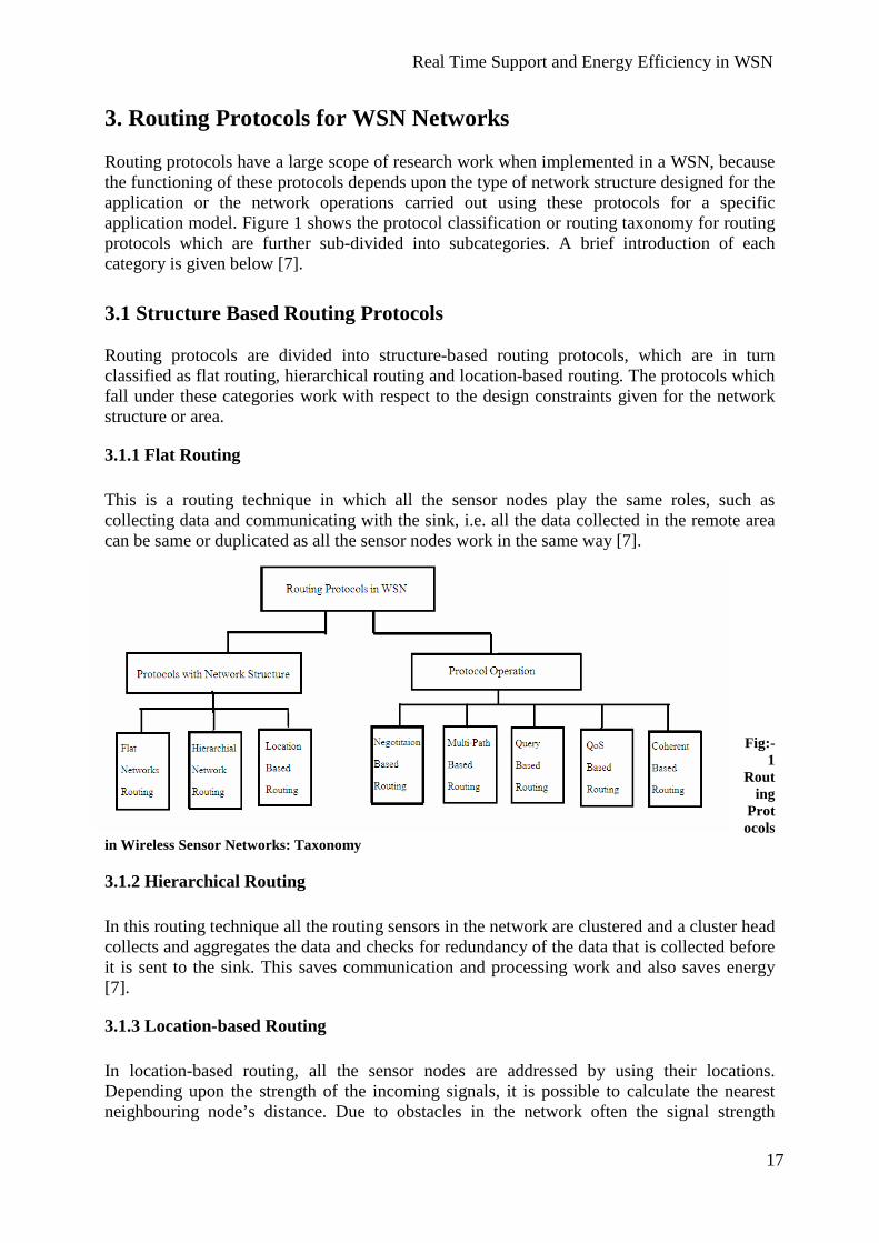
3. Routing Protocols for WSN Networks Routing protocols have a large scope of research work when implemented in a WSN, because the functioning of these protocols depends upon the type of network structure designed for the application or the network operations carried out using these protocols for a specific application model. Figure 1 shows the protocol classification or routing taxonomy for routing protocols which are further sub-divided into subcategories. A brief introduction of each category is given below [7].
3.1 Structure Based Routing Protocols Routing protocols are divided into structure-based routing protocols, which are in turn classified as flat routing, hierarchical routing and location-based routing. The protocols which fall under these categories work with respect to the design constraints given for the network structure or area.
3.1.1 Flat Routing This is a routing technique in which all the sensor nodes play the same roles, such as collecting data and communicating with the sink, i.e. all the data collected in the remote area can be same or duplicated as all the sensor nodes work in the same way [7].
Fig:-
1 Rout
ing Protocols
in Wireless Sensor Networks: Taxonomy
3.1.2 Hierarchical Routing In this routing technique all the routing sensors in the network are clustered and a cluster head collects and aggregates the data and checks for redundancy of the data that is collected before it is sent to the sink. This saves communication and processing work and also saves energy [7].
3.1.3 Location-based Routing In location-based routing, all the sensor nodes are addressed by using their locations. Depending upon the strength of the incoming signals, it is possible to calculate the nearest neighbouring node’s distance. Due to obstacles in the network often the signal strength

Real Time Support and Energy Efficiency in WSN
18
becomes weaker and nodes find it difficulty in finding the nearest neighbour nodes, SMECN performs well in such situations also by creating a sparse graph of the network nodes before transmitting to the next node. All the nodes in the network exchange this data in order to know about neighbouring nodes. This is useful for communicating and transferring information. As energy is the major factor of concern in routing protocols, location-based schemes demand that nodes should change their state from active to sleep mode when there is no activity. The more nodes in sleep mode, the more energy is saved. There are many location-based schemes of which GAF (Geographic Adaptive Fidelity) and GEAR (Geographic and Energy aware Routing) are two examples.
3.2 Protocol Operation Based Routing Protocols Routing protocols taxonomy has another basic and important classification, namely operation-based routing protocols, which is in turn divided into multi-path based, query-based, negotiation-based, quality-of-service (QoS) based and coherent-based routing protocols. The protocols which come under this classification work according to the network-structure operation, or the way the structure needs the protocols to work depending upon the sudden changes it undergoes.
3.2.1 Multi path-based These protocols are efficient in handling multiple paths. Nodes send the collected data on multiple paths rather than using a single path. The reliability and fault tolerance of the network increases as there is, as long as it is possible, an alternative path when the primary path fails.
3.2.2 Query-based Query-based routing propagates the use of queries issued by the base station. The base station sends queries requesting for certain information from the nodes in the network. A node, which is responsible for sensing and collecting data, reads these queries and if there is a match with the data requested in the query it starts sending the data to the requested node or the base station (here). This process is known as Directed Diffusion [6] where the base station sends interest messages on to the network. These interest messages, which move in the network, create a path while passing through all the sensor nodes. Any sensor node, which has the data suitable to the interest message, sends collected data along with the interest message towards the base station. Thus, less energy is consumed and data aggregation is performed on a route.
3.2.3 Negotiation-based These protocols use high-level descriptors coded in high level so as to eliminate the redundant data transmissions. Flooding is used to disseminate data, due to the fact that flooding data are overlapped and collisions occur during transmissions. Nodes receive duplicate copies of data during transmission. The same data content is sent or exchanged again and again between the same set of nodes, and a lot of energy is utilized during this process. Negotiation protocols like SPIN [15] are used to suppress duplicate information and prevent redundant data from being sent to the next neighboring nodes or towards the base station by performing several negotiation messages on the real data that has to be transmitted [3].
Real Time Support and Energy Efficiency in WSN
19
3.2.4 Quality of Service (QoS)-based In this type of routing protocol, both quality and energy have to be maintained within the network. Whenever a sink requests for data from the sensed nodes in the network, the transmission has to satisfy certain quality-of-service parameters, such as, for example, bounded latency (data has to be sent as soon as it is sensed without delaying any further) and bandwidth consumed. Sequential Assignment Routing (SAR) [26] is one of the first routing protocols that use the notion of QoS in routing decisions. Routing decision in SAR depends on three factors: energy consumption within the network by the sink and the nodes, QoS of each path in the network, and priority level of each packet sent [8].
3.2.5 Coherent-based In a WSN, the sensor nodes collect data and send it to the nearest neighbours or the sink within the network. In this process, the processing of the collected data is the most important event. There are two types of data-processing techniques followed within the network structure: coherent and non-coherent data processing based routing. All the nodes within the network collect the data and process it before sending to the next nearest node for further processing. This technique is called non-coherent data process routing and the nodes that perform further processing on the data are called aggregators. In coherent routing, after minimum processing, the data is forwarded to the aggregators. This minimum processing includes functions like time stamping or duplicate suppression. This technique is energy efficient as all the processing is done by the nodes, which reduces the total time and energy consumption [8].
3.3 Additional Classifications Protocols are further classified as proactive, reactive and hybrid, depending on the type of communication routes processed within the network for data transmission from the source to sink. In Proactive routing protocols all the paths are calculated before the sink makes an initiation to communicate with the nodes in the network, where as in Reactive routing protocols, the path values are calculated only when required. Whenever a sink wants to contact a particular node, the path values are calculated and the best path is selected for data transmission. Hybrid routing protocols, as the name suggests, is a combination of both proactive and reactive protocols, which decides whether to calculate the path from the sink to the source, depending on the type of communication. Generally, it is suggested that table-driven (proactive) routing protocols are better when we consider the nodes as static. The reason is that a lot of energy can be saved compared to reactive routing protocols that depend on the discovery of the best route path for data transmission. In proactive routing it is not necessary to search for the nearest neighbours for every next hop when data is transmitted.

Real Time Support and Energy Efficiency in WSN
20

Real Time Support and Energy Efficiency in WSN
21
4. Detailed Study of Routing Protocols Routing protocols are divided into many categories like structure-based routing protocols and operation-based routing protocols. All these sub layers like flat routing, location-based, multi-path-based, query-based and negotiation-based comes under the classes like hierarchical-based routing, data-centric routing, location-based routing and network flow – quality-of-service based routing protocols.
4.1 LEACH (Low Energy Adaptive Clustering Hierarchical) The current interest in wireless sensor networks has led to the emergence of many application oriented protocols of which LEACH is the most aspiring and widely used protocol [9]. LEACH can be described as a combination of a cluster-based architecture and multi-hop routing. The term cluster-based can be explained by the fact that sensors using the LEACH protocol functions are based on cluster heads and cluster members. Multi-hop routing is used for inter-cluster communication with cluster heads and base stations. Simulation results shown in [12] that multi-hop routing consumes less energy when compared to direct transmission. We have stated that wireless sensors sense data, aggregate them and then send data to the base station from a remote area using the radio transmission scheme as communication medium. Data which is collected by the sensors is sent to the base station. During this process a lot of problematic issues occur, such as data collision and the data aggregation. LEACH is well-suited to reduce the data aggregation issues using a local data fusion which performs a compression of the amount of data that is collected by the cluster head before it sends it to the base station. All sensors form a self-organized network by sharing the role of a cluster head at least once. Cluster head is majorly responsible for sending the data that is collected by the sensors to the base station. It tries to balance the energy dissipation within the network and enhances the network’s life time by improving the life time of the sensors [10]. The operations that are carried out in the LEACH protocol are divided into two stages, the set-up phase and the steady-state phase. Set-up Phase In the set up phase, all the sensors within a network group themselves into some cluster regions by communicating with each other through short messages. At a point of time one sensor in the network acts as a cluster head and sends short messages within the network to all the other remaining sensors. The sensors choose to join those groups or regions that are formed by the cluster heads, depending upon the signal strength of the messages sent by the cluster heads. Sensors interested in joining a particular cluster head or region respond back to the cluster heads by sending a response signal indicating their acceptance to join. Thus the set-up phase completes [12]. The cluster head can decide the optimal number of cluster members it can handle or requires. Before it enters the steady-state phase, certain parameters are considered, such as the network topology and the relative costs of computation versus the communication. A TDMA Schedule is applied to all the members of the cluster group to send messages to the cluster head, and then to the cluster head towards the base station. Figure 2 below shows two phases of a sensor in a LEACH protocol: all the sensors form as cluster members to the cluster heads and in the

Real Time Support and Energy Efficiency in WSN
22
second phase cluster heads perform the transmission of data to the sink in a multi-hop structure. A direct transmission scheme is also shown below
Fig:2 LEACH operation showing set-up, steady state phases using multi-hop, also showing direct transmission Steady State Phase As soon as a cluster head is selected for a region, all the cluster members of that region send the collected or sensed data in their allotted TDMA slots to the cluster head. The cluster head transmits this collected data in a compressed format to the base station which completes the second phase, called the Steady State Phase. Once the steady-state finishes the data transmission to the sink, the whole process comes to an end and a new search for the forming of cluster heads for a region and new cluster-member formation begins. In short, it can be said that a new set/up phase and steady state starts with the end of data transmission done to the sink. This alternative selection of cluster heads within the region, which is carried among the sensors in a self-organized way helps in reducing or lowering the energy that is utilized. There is a possibility that all the sensors might not be too close to the cluster head so the amount of energy that is utilized by the farther sensor is not equal to the amount of energy utilized by the nearest node. In order to minimize this, cluster heads formation or the role of

Real Time Support and Energy Efficiency in WSN
23
cluster head is performed by a rotation among all the nodes in the group. LEACH minimises global energy usage by distributing the load of the network to all the nodes or cluster members at different intervals [12]. All the cluster heads send the data which is collected towards the base station in a compressed format. All the cluster heads may not be close to the base station so they send the compressed data to the neighbouring cluster heads, and in this way, a multi-hop routing network is formed. LEACH plays a randomised rotation of the cluster head in order to save the high energy that is dissipated while transmitting data to the base station. This rotation is observed within all the sensors so as not to drain the energy or battery of a single sensor. Now, let us consider some facts about LEACH when compared to direct transmission schemes. If we consider a random network where there are 0 or 100 % cluster heads, the amount of energy dissipated by the cluster heads and their cluster member is equal to the energy that is dissipated in a direct communication. This shows us that if we have an optimal number of cluster heads in our network that works in transmitting the collected data from their respective cluster members, we can possibly achieve better results by way of saving energy dissipation. Let us assume that there are N1 cluster heads in the network, which maintains perfect energy balancing within the sensors in the network. If the amount of cluster nodes is less than N1, all the nodes in the network have to transfer the collected data at a higher transmission range in order to reach a particular cluster head. If there are more than N1 cluster heads, the distant node in the network has to transmit the collected data to the nearest cluster head, which does not reduce the sustainability [11] [12]. Multiple Clustering Let us assume that cluster A is sending or sharing data with cluster B. If this transmission affects the nearby cluster C, the data is either corrupted or destroyed by the interference of the neighbouring cluster C. In order to reduce this issue, LEACH has introduced CDMA codes, i.e. when a node in a group has decided to become a cluster head, it chooses a code from the list of spreading codes on random and announces it within the network and the group. This helps it in filtering or sorting out the data that is received from other groups containing different spreading codes [12]. Hierarchical Clustering We have seen that cluster members can randomly form cluster heads within the groups as well as multiple clusters to avoid data collisions using CDMA code techniques. This can be extended to forming hierarchical clusters. Here the cluster heads communicate with the super cluster heads, i.e. the cluster heads of the above hierarchy and so on, towards the base station. This simplifies the data transmission process in large networks, which saves a tremendous amount of energy [12]. Simulations of LEACH are reported in [10], where LEACH is compared to LEACH-C, MTE routing and static clustering in terms of system lifetime, energy dissipation, amount of data transfer, and latency. The test code is provided at http://www-mtl.mit.edu/research/icsystems/uamps/cadtools.

Real Time Support and Energy Efficiency in WSN
24
Protocol Performance in surveillance applications LEACH uses cluster-formation using the nodes deployed on the network to sense data and forwards it to the base station. As we focus on surveillance applications, it is not possible to accept that LEACH uses a minimum number of nodes to form clusters, i.e. the number of cluster members required by a cluster head is limited because a large number of cluster members can create overhead or high traffic loads at the sink. In a surveillance application we cannot ne restricted to a specific number of nodes that have to sense an area like a war field. A continuous data-delivery model is opted for by LEACH to transfer a maximum amount of data to the sink. If we use LEACH in a habitat-monitoring application like retina scanning, there is a possibility that the performance is much better as the network density is small and requires only one time-node deployment. These lead it to pose low latency and high scalability with larger network life time. The one factor which is ignored in LEACH is the quality of service. While concentrating on energy conservation forming clusters to transfer data, the QoS factor is kept low which shows that if a cluster head is failed in transmitting data there is no other path to resend the lost data packet. The topology i.e. the structure of cluster formation changes every time a transmission of data is completed with the sink or base station.
4.2 PEGASIS (Power Efficient Gathering in Sensor Information Systems) Wireless sensor nodes sense data and send it directly to the base station or they perform a clustering procedure as in LEACH. LEACH is known for cluster formation which contains cluster members sensing the data and the cluster head which gathers the data collected in a fused manner (all the data is sent as a single packet) to the base station. This procedure has gained in conserving a lot of energy that would otherwise be wasted. PEGASIS is an extension to LEACH; it has better ways of conserving energy which last even more than using cluster mechanism in LEACH [12]. If we have nodes in the network which are at some distance from the base station, the easiest and the simplest way of transmitting the sensed data to the base station is to transmit it directly, which may lead to quicker depletion of energy in all the nodes. The nodes at a large distance away from the base station are depleted quicker than the nodes which are closer to the base station as they need some extra energy to reach the farthest base station. Another approach where energy is consumed in low amounts is by forming cluster heads and cluster members using the sensor nodes in the network. Cluster members perform the sensing and computing the data (Data Fusion) and the cluster heads transmit the fused data to the base station. All the nodes in the network take their chance to act as cluster heads to send the fused data to the base station; again the farthest cluster head needs some extra energy to send the data to the base station. The key idea in using PEGASIS is that it uses all the nodes to transmit or receive with its closest neighbour nodes. This is achieved by the formation of a chain as shown in the Figure 3 below. All the nodes which collect the data fuse it with the data received by the neighbour node and transmit it to the next-nearest neighbour. In this way all the nodes receive and fuse their data, and pass it to the next neighbour in a chain format till they all reach the base station. Every node in the network takes turns as a leader of the chain and the one responsible to transmit the whole fused data collected by the chain of nodes to the base station [13]

Real Time Support and Energy Efficiency in WSN
25
Fig:-3 Formation of chain using nodes in PEGASIS In this way the average amount of energy spent by each node is reduced. Greedy algorithms are used to see that all nodes are used during the chain formation. PEGASIS assumes that all the nodes with varying or low energy levels can be compensated in order to to calculate the energy cost of the transmissions with the remaining energy they are left with. It is not necessary that all the nodes need to know its neighbouring nodes, the base station can determine the path or form the chain for all nodes, or all the nodes can determine their neighbouring nodes by sending a signal. Depending upon the signal strength, the nodes adjust their signal such that they hear only the nearest neighbours in the network. From Figure 4 below the operation of PEGASIS is clearly understood. A greedy algorithm is applied to form a chain among all the best nodes that are at a one-hop distance from each other and to the base station. If the farthest node is selected, it starts transmitting the data. For example, if node 4 start the chain formation process and it sends the signal to the nodes in the network to find the nearest neighbour, node 3 is the nearest, so it transmits the sensed data. Upon receiving the data from node 4 node 3 starts finding the nearest neighbour by sending signals and when it finds that node 2 is the nearest, it fuses its own data with the data received from node 4 and transmits all this data to node 2. Node 2 finds node 1 as the nearest and transmits the sensed data with the fused data (the whole data is formatted a single packet). Now node 1 is the nearest node to the base station, so it acts as a leader and transmits all the data. Only the first node in the chain have nothing to fuse except the data it has during the chain formation, the remaining nodes all have some data to append with the received data from other nodes [13].

Real Time Support and Energy Efficiency in WSN
26
Fig: 4 Flow of Data in PEGASIS forming Chain to reach BS This approach will distribute the energy load evenly among the sensor nodes in the network as it uses all the nodes of the network to form the chain and perform simple data forwarding operations. If any node dies in the chain, a new chain is formed, eliminating the dead nodes. From the simulation reported in [13], it is clear that PEGASIS improves on LEACH by saving energy at different stages, such as for example cluster-member forming and cluster heads. Here all the nodes have an equal chance of becoming the leader once and transmit data to the base station in one round. An energy balance is estimated on the nodes in the network which conserves lot of energy. The amount of nodes that die during the chain process is reduced when compared to LEACH for all types of network sizes and topologies. The network lifetime is increased, as all the nodes actively participate and deplete the equal amount of energy on the whole [13]. A simulation analysis of PEGASIS is reported in [13], comparing it with the LEACH protocol using different network topologies. Many experimental results proved that PEGASIS is supporting longer network lifetime, more balanced energy dissipation and higher performance. Protocol Performance in surveillance applications PEGASIS uses a greedy algorithm to form a chain using the nodes in the network to transmit data to the base station; it has no location awareness of the sensor nodes in the network and looks only for the closest neighbour that it can reach. Discovering a new route is difficult if a node fails, as it has a fixed path every time before it starts a new route towards the sink for transmission. Though its approach in conserving energy is better, it lacks in maintaining focus on quality-of-service factors. For instance, it cannot resist uneven traffic distribution for all those nodes which are not in the single-hop range, it has to make a multi-hop structure for adding such nodes.

Real Time Support and Energy Efficiency in WSN
27
4.3 SPIN (Sensor Protocol for Information via. Negotiation) A wireless sensor network consists of many sensors that are deployed in different regions and range. Accessing a particular event’s data from a specific region or area can make a lot of difference; immediate action can be taken on getting that specific and concise data from a specifically targeted area. Data is collected from all sensors and transmitted redundantly over the network, which leads to inefficient utilization of energy and processing while aggregating the same set of data at the sink. In order to solve these types of issues, data centric routing schemes have evolved, which send queries from the sink to the sensors in the network within a selected location. Attributes are used to request data from the sensors. SPIN (Sensor Protocols for Information via. Negotiation) is the first data-centric protocol that was designed for wireless sensor networks and has many similarities to direct diffusion. It is efficient in reducing the redundant data and save energy [16]. The motivation behind developing SPIN is due to the dissemination of data. Dissemination is the process of collecting the observations of the whole set of individual sensors which are deployed in the network, where all sensors are treated as sink nodes. The work assigned to these sensors is to collect the complete view of the environment in the form of data, and enhance a fault-tolerant network structure. Energy consumption both during computation and communication must be controlled to extend the life time of the sensors within the network. A few drawbacks in the sophisticated protocols like implosion, overlapping and resource blindness have led to the development of SPIN [15]. Data Implosion Conventional protocols like classic flooding send a piece of data to each and every node, which copy the received data and send them to their neighboring nodes. In this way data is disseminated quickly within the network and uses a large amount of bandwidth assuming that all the links are connected between nodes. This can be clearly understood from Figure 5 shown below [R.14]. Here node A sends a piece of data to its nearest neighbor’s node B and node C. After receiving the data, node B and node C copy and send the data to its nearest neighbors node D without trying to find out whether it already has the data or if it really needs to have the data collected by node A. Now node D has duplicate copies of data which are sent by both node B and node C not knowing that either of them are sending it to the same neighbor node D. This leads to implosion where energy is wasted in terms of both communication and computation [14]. Fig: 5 Conventional Classical Flooding with implosion problem

Real Time Support and Energy Efficiency in WSN
28
Data Overlapping: Sensor nodes which are distributed over a large area, often overlap within their geographic region and they carry overlapped data that is sensed in these areas. This concept is clear from Figure 6 which is shown below and redrawn from [R.14]. Here node A collects data from region X and sends it to its nearest neighbor C as (a, c) and the node B collects the data from its region Y and sends it to the nearest neighbor C as (b, c). The figure shows further that node C which has received data from both node A and B has a common data (c). This data which represents as ‘c’ is that which is collected from the region of the intersection of the regions X of node A and region Y of node B. Sending two similar or duplicate copies of data to the same node C leads to a lot of energy waste in terms of both computation and bandwidth . Implosion can be solved in SPIN as it is restricted to the network topology but overlapping includes both the network topology and mapping of sensor nodes [14]. Fig: 6 showing the Geographic Overlap mechanism Resource blindness In the conventional protocols like classic flooding, the sensors perform the sensing and sending activities without any concern about the amount of energy that is left in the neighbor sensors. A network sensor does not look for the amount of energy that is required for the computation process of achieving new data from its neighbor nodes or during the communication of the data that is transmitted to the next neighbor. SPIN protocol overcomes these issues of flooding and resource blindness using negotiations and resource adaptation. To eliminate the flooding and overlap effects on the network, SPIN nodes negotiate with each other before transmitting data. SPIN checks that only useful information is transferred within the network. Data that needs to be transmitted to the neighboring nodes is addressed using a meta-data name. SPIN uses three types of messages also called Meta data before transmitting data among the neighbors in the network. Every node that wants to share the data with the nodes in the network sends this meta-data to enquire or know if any of the nodes are interested in exchanging data. Meta-data are used for exchanging information, as sharing directly sensor data between two nodes is expensive in terms of energy. Nodes cannot respond to all the data messages sent by all other nodes

Real Time Support and Energy Efficiency in WSN
29
because of the changing topology or network structure. To save energy resources, these meta-data help the node to choose specific type of data from specific nodes [14]. Meta-data describes the characteristics of the data or information that needs to be shared. The meta-data must be smaller in size than the original data and it should be easily distinguishable from other data types. Meta-data are application-specific and they always take their geographic location or a unique ID while communicating with the neighbor nodes. Three types of meta-data messages are exchanged between the nodes: ADV: - A new advertisement meta-data is used when a SPIN node has some new piece of information that it would like to share or exchange with other nodes in the network. REQ: - A request meta-data is sent by the SPIN node which is interested in participating in data exchange with the node that has a new or interesting type of data. DATA: - The actual data that has to be shared between two nodes which are involved in exchange. The SPIN node A has new information within it and would like to share it with the nodes in the network. It sends an ADV message to the nearest neighbors. This ADV meta-data has the field which describes what type of data it is and what communication time and computations are required. Upon receiving this meta-data, the nodes which are interested in having this new data will send back an REQ meta-data to the node, and those which are not interested in the new data do not respond. Once the transmitting node receives the REQ message, it starts transmitting the DATA. In this way, the data which is received by the nodes starts to disseminate to the nearest nodes [15]. Here we can see that only nodes which are in need of the data or interested in having the new data respond back to the ADV-sent node and this eliminates the overlapping and implosion within the network. SPIN-I belongs to the SPIN family, which uses a three-way handshaking process to transmit the information within the whole network. SPIN-I needs to have the knowledge of all the neighbor nodes which are at a single-hop distance so that it can easily reestablish communication with them, if there is a communication or path loss between nodes by sending messages like Re-Adv and Re-Req instead of ADV and REQ [15] . In Figure 7, we can see that a node wants to share data with its neighbor nodes. It sends an ADV message and if there is any node interested in receiving data, it sends a response message back to REQ. Thus the node starts sending the DATA to the requested sensor. Once the node receives the data, it starts sending ADV messages to all other neighbor nodes to see if any node is interested. If the neighbor nodes are interested, they send back response messages or if the node is not capable of further computation like sending an REQ messages or receiving DATA it does not respond back. These are the five stages a node can pass through depending upon the energy reserves it has and need for data.

Real Time Support and Energy Efficiency in WSN
30
Fig: 7 Five stages of SPIN showing the Three-Way Handshaking SPIN-II, which is a slight update of SPIN-I, has the ability to prevent the nodes from resource blindness. All the nodes have their own resource managers which keep updating the node about the amount of energy that is left within in order to further carry on the process of data sharing or data transferring. If a node has much lower energy than the required amount, it stops responding to the ADV messages sent by other nodes which are interested in sharing data or it does not send any more REQ messages to the nodes from which it is interested in receiving. Nodes participation is reduced within the network when it approaches a very low energy say threshold level. Whenever it receives ADV messages it initiates a process only when it is sure that it can complete all the three stages of data receiving from the neighbor nodes [15]. Heinzelmann et al [15] has reported simulations of SPIN protocol family using SPIN-I, SPIN-II, SPIN with flooding and SPIN with gossiping and an ideal dissemination. Gossiping is an alternative to classic flooding in which energy is conserved while transmitting data to its neighbors. A node forwards the data to a randomly-selected neighbor in the network but not to all the neighbors as in classic flooding. As a single random node is chosen to transmit the data no implosion is observed in the network. A single data packet travels to the node and when that nodes starts sharing the data packet with all the other nodes in the network that are interested a time delay is observed in the network. It is also not safe to use gossiping in all types of scenarios because if there is a loss of connection in the network, data is never passed on to the next node. From the Figure 8 below we can see that node A sends the data to B and node B transmits the data to node C. It saves a copy for further use in its memory and if there is a connection lost between its neighbor nodes D it can never send data to it. In order o send data to D, node C has to back track to node B and see some other alternative of sending data which may at times leads to the overlapping issue. This approach can be clearly understood from Figure 8 given below. Energy dissipation is very low when compared to classic flooding; it has very few computations and communications that are carried out between nodes [14].

Real Time Support and Energy Efficiency in WSN
31
Fig:-8 showing the Gossiping in wireless sensor networks On implementing SPIN we can observe the amount of data acquired at a point of time and the energy dissipated over time intervals is high when the energy resources are unlimited. When this energy resource is limited the amount of energy performance is 25% energy of the amount of energy required in flooding. Further, SPIN-II distributes 60% more data per unit energy than flooding as calculated in the simulation carried in [15]. Thus, we can conclude that SPIN-I and SPIN-II are simple protocols that efficiently disseminate data and are well-suited for environments where sensors are mobile (move) and forwarding decision can be taken based on the local neighborhood information. In [14], simulations using the network simulator NS-II and protocols like SPIN, SPIN-II, gossiping, and flooding, are reported. The results stated that SPIN-I achieves comparable results to classic flooding protocols, and in some cases outperforms classic flooding. In terms of energy, SPIN-I uses only 25% as much energy as classic flooding protocol. SPIN-II is able to distribute 60% more data per energy unit than flooding. Protocol Performance in surveillance applications SPIN uses the technique of gathering information by sending queries from an exact location. For a surveillance application it is a must to get a particular type of data from an event-triggered region. It supports movement among the nodes which helps in changing the geographic location and covering a vast area of surveillance and can also adjust to the topology changes that take place. It shares data with neighbour nodes only when they are interested in alternatively saving much of the energy in computation and communication.
4.4 GEAR (Geographic and Energy Aware Routing) Sensor networks are usually largely composed of deployed sensor nodes in a vast area which are scattered randomly in order to gather all sorts of data on an event that is triggered. The major disadvantage to these randomly-scattered sensor nodes in a particular application like surveillance is that they are unattended. Because of this energy has become a major issue of concern as the sensor nodes cannot be replaced or replenished at regular intervals. In
Real Time Support and Energy Efficiency in WSN
32
applications like surveillance it would be far better if we know the exact position of the sensors in order to locate particular information of events like tracking movements of armed vehicles during night time or on a foggy day. We need to have an efficient query processing within the network so that we can disseminate a query to a particular region, for which location knowledge is a must. Unless we know the exact position of the target region, we cannot direct the query and get the required data or information from specified sensing nodes and save energy of all other remaining sensors which are drained by using the flooding data mechanism all over the network. Conventional routing protocols used many greedy algorithms to forward data to a specified region like Restricted flooding which was of major concern in the early protocols using a search mechanism to navigate through holes (the nodes which are totally drained of energy but still in the network as if they are part of the communication path). GPSR (Greedy Perimeter Stateless Routing) used a planar graph for a network graph to disseminate packets [17]. Scalable Location Update Routing Protocol which uses a scheme that has the complete knowledge of the route path i.e. is it has perfect information of the location of all the nodes in the networks using which it destines the packets to reach a particular source or destination in a pre described path [17]. GEAR Algorithm Let us now discuss the working and structure of GEAR routing protocol. Here we are concerned with a protocol that disseminates queries directly to the sensor nodes of a network and extract the required data from a specific region called target region. The Geographic and Energy Aware Routing (GEAR) scheme uses an energy-aware and geographically-informed neighbour selection heuristic to route a data packet to a target region. It proceeds internally by applying a recursive geographic forwarding technique to disseminate a data packet directly to the sensor node inside the target region. Two scenarios are possible while forwarding a data packet to the target region i.e:
i) If we have a neighbour node closer to the target region, then GEAR picks up the next hop towards a node that is much closer to the destination or target region.
ii) If we have all the neighbour nodes farther from the target region, then GEAR picks the next hop towards the neighbour node depending upon the neighbour cost.
Once a packet is delivered to a target region, an internal-routing scheme starts. Here a recursive geographic-forwarding algorithm is usually used to disseminate the data packet to the target node. Under low traffic conditions, when recursive geographic forwarding scheme does not apply as it starts draining energy by rotating around the holes with the data packet in search of target node, we use a restricted flooding approach [19]. Assumptions
1) A packet that is disseminated over the network has a target node in some region. 2) Every node in the network knows its own location and the amount of energy it needs
to further continue the processing 3) Every node needs to know the location and energy level of its neighbour protocols by
sending a simple HELLO protocol.

Real Time Support and Energy Efficiency in WSN
33
4) Every link in the network is bi-directional: if a node can listen to other node Ki, it can also have a transmission range Ki.
Cost function can be minimized as c (K, S) when all the nodes have equal amount of energy, In this situation the classical greedy geographic-routing algorithm is performed by randomly choosing a nearest neighbour to the target region S. Cost function c (K, S) can be minimized when all the nodes in the network are at equidistance to each other: in this position it performs the load splitting among the neighbours [20]. Algorithm Implementation From figure 7 we can see that the node K has neighbours which are at equidistance from the target region. So according to the algorithm assumptions, a classical greedy choice of next hop selection is done so that the learned cost is minimized as l (Ki, S). The next hop neighbour is chosen to route the packets. If the node K receives a data packet, it transfers it to this nearest neighbour as it has updated its learned cost. Minimizing the learned cost alters the consumption of energy in the network, so that a balanced energy usage is done in selecting and forwarding the data packet to the nearest neighbour. Here the learned cost l (Ki, S) is equal to the estimated cost of the neighbouring node Ki as there are no holes (drained nodes in between). From Figure 9 we can see that when a node K has neighbouring nodes far from the target region, its learned cost l (K,R) has to be updated and because of the holes in the network its value becomes not equal to the estimated cost e(Ki,R). Let us assume that there are nodes in the network of which some node K has its neighbour nodes as B, C, D, G, H and I of which the nodes G, H, I are depleted or drained of energy and cannot be used for routing packets to the destination region S. When the region S receives a data packet X it has a chance to forward it to any of the neighbouring nodes B, C, D which are nearer to the target node S than itself. It calculates the estimated cost and checks with its learned cost so that the nearest neighbour with least cost value is chosen as the next hop neighbour. Suppose the learned cost of the following nodes is as follows: B � c( B,S) = l ( B,S) = 2.5 C � c (C,S) = l ( C,S) = 2 and D� c (D,S) = l (D,S) = 2.5 Fig:-9 showing the routing path via. Calculating the learned cost Now the node K chooses the least cost neighbour as C and it forwards the received packets. Upon receiving the packet node, C checks for its neighbour nodes and finds that all the other

Real Time Support and Energy Efficiency in WSN
34
nodes except node D and B are drained (G,H,I) so it chooses a least cost path towards the target node S. It now updates the learned cost value as l (C, S) = l (B, S) + c (C, B) which implies as �l (C, S) = 2.5 + 1 = 3.5. As the node K receives a data packet X, it forwards it to the nearest neighbour C and from C the packet is traversed along the route B towards the destination S node. As the learned cost value of K� B is less when compared to K�C � B, K tries to update its learned-cost value favouring node B after oscillating several times between node B and C traversing data packet X. Once the data packet safely reaches the target node S through the least cost route selected, the learned cost value will be corrected to one hop back. If the path length K� S is n, the learned cost will converge after the node delivers n number of packets towards the same destination node S. This will enhance the route by effectively circumventing holes in the network and at the same time it will avoid routes that lead to the depleting nodes surrounding the holes [21]. Recursive Geographic Forwarding Once the packet is forwarded from node B, it reaches the boundary of the target region S. This can be seen in Figure 10 below, denoted in red circle as node B. From region S the packet has to be targeted to the exact node, which can be done by any conventional flooding protocol. If we use a conventional flooding scheme, the data packet X has to be broadcasted and all the nodes in the region get this data packet X even though they are not intended to receive it. This causes a lot of energy consumption and is also very expensive. In order to reduce these inefficiencies, an energy-efficient routing algorithm is introduced. The recursive geographic forwarding algorithm is used to disseminate the packet inside the target region S. Once the data packet reaches its target region, it checks for the presence of the target node in the region S. If we assume that there are a large number of nodes within the target region, it becomes expensive to check with all the nodes in the region. Sub regions are created in the target region and the data packet is duplicated into an equal number of sub regions and then sent. This forwarding strategy continues within the sub regions until the appropriate target node is reached. If the sub region contains only one target node there would be no more recursive splitting of the data packet within the target region S. In order to find out weather there exits only one node we have to check whether the farthest node is in the transmission range and there exist no other neighbour node to the target node [21]. Fig:-10 Recursive Geographic Forwarding GEAR uses an energy-aware and geographically-informed neighbour selection heuristic procedure to route a packet to the destination or target region. It uses a recursive geographic
Real Time Support and Energy Efficiency in WSN
35
forwarding or restricted forwarding strategy depending upon the density of the network. This leads to a balanced-energy consumption within the network and also extends its network life time. It has been proven that GEAR is efficient in routing maximum percent of data packet to the destination when compared with conventional protocols like GPSR. both in uniform and non-uniform traffic situations. GEAR has a moderate latency factor as it does not support one particular communication path. It keeps on changing depending upon the cost factor and it has a limited scalability as nodes get drained easily by rotating the data within the region if there is no destination node found. Data on the network travels in those paths which are already calculated, as the least cost paths which makes it achieve an average traffic overhead on the network [19][21]. Simulation of GEAR is reported in [18]. Situations like uniform traffic and non-uniform clustered traffic with varying network sizes are simulated. The simulation results show that for both kinds of traffic GEAR delivers significantly 40 to 100 times more packets than flooding and delivers 25-35% more packets than GPSR. Protocol Performance in surveillance applications GEAR uses an energy-aware and geographically-informed neighbor selection process to route data in large amounts to the base station and a hybrid data-delivery model is implemented to transfer data to the base station as every node has to perform some least cost path calculations before forwarding the data to the destination. GEAR can handle average amounts of data traffic on the network and it can handle nodes from 20 to 100, which resembles a small network. When used in surveillance application like home or office monitoring, GEAR [21 can perform well and show better results as the node deployment in this kind of application is iterative. The quality of service factor is low in this protocol as it has network instabilities and resource limitations like limited battery, limited bandwidth and memory.
4.5 GAF (Geographic Adaptive Fidelity) Almost all protocols are efficient in routing packets and in saving a lot of energy by forming clusters or organising a random coordinator to do the functional job, but they all lack in few things which are almost unavoidable, such as overhearing on the medium or network, protocol like PAMAS [22]. Every time a packet is forwarded, all the nodes have to check whether the packet is destined for them or if they have to forward it to some other neighbouring node so that it reaches the correct destination. We have seen that nodes consume a vast amount of energy while sending or receiving data, it is stated that nodes uses some physical amount of energy when they are in the idle or listening state. Energy dissipation during the idle state cannot be ignored, as it is statistically proven that the energy consumed by a node in idle-receive-transmit is in the ratio of 1:1.2:1.7 [23]. The ratio shows that the amount of energy that is wasted when the node is in idle state is less that that compared to receiving data from other nodes and transmitting data to the neighbour nodes or to the sink. The energy that is wasted when the nodes are in the idle state can be saved by turning off the radios when they are not in use, because energy cannot be saved only by reducing the number of transmissions or receptions of data packets or even by reducing the functions at the sensing nodes. One advantage of turning off the radios is that we can save not only the energy that is wasted during the idle state, but also conserve energy that is wasted by all the nodes in the

Real Time Support and Energy Efficiency in WSN
36
region by overhearing the same data packet. Switching off the intermediate nodes in an order can make us achieve connectivity within the network while there are multiple paths existing between nodes. This can be illustrated using an example which implements this theory [18]. Figure 11 below redrawn from [18] shows the virtual grid formation using the nodes in the network for GAF. There are 5 nodes in the network and node 1 can communicate with nodes 2, 3, and 4 and these three nodes in turn communicate with node 5. If node 1 wants to communicate with node 5, it has to pass through any of the 2, 3 and 4 nodes. If we assume that all these nodes 2, 3 and 4 are equal in all functionalities, we can make one node active and let the other two nodes 2 and 3 go to sleep so that we can conserve the energy that is wasted by only making them active for overhearing the traffic that is passing through one of these nodes to reach node 5. This is known as routing fidelity where both nodes 1 and 5 are communicating by making intermediate nodes go into sleep mode and using only one efficient node as their routing partner. Fig:-11 Virtual Grid in Geographic Adaptive Fidelit y [R.18] GAF Algorithm The name Geographic Adaptive Fidelity states that it locates nodes in the network and makes the best use of them to have a better fidelity. All the nodes use a location-identification technique to locate itself within the network along with its nearest neighbours by using location-information systems like GPS. In GAF, all the nodes arrange themselves according to grids also called virtual grids. All the nodes in the network divide themselves in virtual grids and all those nodes which are under a same grid coordinate among themselves to see who will go into sleep state and for how long. Load balancing is performed and a single node will not get drained with extraneous work. It can also be very simple to define virtual grids as all the nodes which are in grid A can communicate with all the nodes in grid B that are adjacent. The time for sleeping is decided or depends on the application and system information. GAF has three state transitions, namely discovery, active and sleeping. Initially Every node starts with the discovery state. In this state the node turns on its radio and starts sending discovery messages to find the adjacent nodes in the same grid. Every discovery message is a combination of certain parameters, such as: Node State: - Discovery, Active or Sleeping Node ID: - The node itself or its current location

Real Time Support and Energy Efficiency in WSN
37
Grid ID: - Every node in the network uses its location information from GPS and its grid size in order to determine its grid id (enat):- Estimated node active time, this value can be set equal to node lifetime, which means that the nodes keeps on using the energy until it dies or drains out of energy. Using these parameters as a node enters a discovery state, it sets its time Td (Discovery time) and sends discovery messages to all the nearest neighbours in its own grid. After broadcasting this discovery message it enters the active state. A node can fall into sleep state if there are other nodes in the grid which are equivalent in handling the fidelity before falling into the active state. In the active state the node sets a timeout value Ta which shows the remaining amount of time for which a node is intended to stay in active state. During its active state a node re-broadcasts its discovery message for given time intervals Td and goes into the sleep state if it finds another node which is equivalent or has an node with higher node rank that can handle communication or routing process. All these three types of state processing can be seen in the Figure 12 given below, which shows node performance during the discovery, active and sleep state [19]. A node enters into sleeping state either from the discovery state or the active state. Before it goes into the sleeping state it cancels all the timers like Ta and Td and power down the radio. In order to get back or wake up into the discovery state, the node has to complete the sleep time Ts, which is decided by the application or system. Fig:-12 showing three state transitions in Geographic Adaptive Fidelity In order to maintain a constant communication medium or routing path between the nodes, GAF has to follow some load-balancing scheme so as to make all the nodes work efficiently and see that the nodes lifetime increases. This can be achieved by assuming that all the nodes in the region are equal, and no node is used fully or depleted till it dies. If the nodes that are in active state for the time interval Ta are brought back to the discovery state, a chance is given to all those nodes which are in the discovery state to handle the further process, among those which strive to become active node members, there might be some nodes with more energy resources, or higher-rank nodez. These nodes set the timer Ta equal to enat and start advertising their discovery messages. The nodes which are in sleeping state set their timers equal to enat, i.e. the sleeping time.

Real Time Support and Energy Efficiency in WSN
38
From the analytical analysis shown in [18] it is clear that the overhead issue in GAF is very low, while there are certain drawbacks like packet loss and route latency. The network lifetime depends upon the density of nodes if there are many nodes in the virtual grid there is maximum scope of high network lifetime because at least one node will stay awake in the grid while all the other are in sleep state handling the route fidelity. If the node density is low there are a lot of chances that the nodes keep on moving so at times if there are no active nodes in the grid the communication path is lost [18]. Simulations of GAF are reported in [20], using a snapshot of ns-2.1b6. GAF is added with AODV implementation from AODV designers and GAF with DSR to compare the performance in terms of energy dissipation and data delivery quality. The simulation result shows that GAF can consume 40-60% less energy than an unmodified ad hoc routing protocol. It also increases the network lifetime proportionally to the node density. Protocol Performance in surveillance applications GAF is one of the location-based routing protocols which route data in large amounts from the nodes that are placed randomly. It uses some GPS location system to track all the nearest neighbors and performs a multi-hop structure in transferring the sensed data to the base station or the sink. Using location information GAF stands high in object tracking by using low power on the network, and proportionally increasing the lifetime of the network. If GAF is applied in a surveillance application it shows better performance as the scalability of the network is static and it poses a moderate latency over the network which makes it produce faster results. The quality of service factor is low because there is no redundant path available if there is a packet loss or if the node is not capable of finding the best path and falls into the energy drained nodes also called (holes). The delay factor is also high as it has to every time calculates for the best path among the nodes and this leads to lot of data waiting in the buffers.
4.6 MECN (Minimum Energy Communication Network) Sensor nodes energy efficient performance is achieved only when they track information about their neighbouring nodes. This information helps in maintaining efficient communication paths and also saves energy, so that they do not get drained at once. Neighbour information is achieved by using location information from systems like GPS. MECN [24] constructs a minimum energy efficient communication network with the nodes for a wireless sensor network. All the nodes in the network have the knowledge of their neighbouring nodes. MECN constructs a small relay region in the surroundings of the node and starts transmission of data to a particular destination node using the intermediate nodes as relay nodes [24]. There are three types of nodes, a transmitting node, a receiving node and a relay node. MECN constructs an enclosure or a sparse graph as shown in the Figure 13 below with all those nodes which act as a neighbouring node to the transmitting node. It selects the path between the transmit node and the receive node from the enclosure graph using the relay nodes which aims at minimum energy dissipation when compared to energy dissipated in direct transmission from the transmit node to receive node.

Real Time Support and Energy Efficiency in WSN
39
Fig:-13 Enclosure and Relay region of transmit-ready node pair MECN finds a relay region for every node in the network using certain path value calculation algorithms like Belmann Ford where the energy consumption factor is considered as its cost factor. Using these relay regions, whenever a node is ready to perform transmission it checks for all its neighbouring nodes relay regions or finds the least cost paths that lead to the destination. It then performs a union of those who form an enclosure or boundary of that sub network. All the relay regions found are globally optimal links in reference to the amount of energy they consume. A condition states that if the destination node is somewhere within the sub network, then the amount of energy used to communicate with it is considerably lower than in direct transmission. [24] The actual concept of MECN is to find the relay regions of the nodes and form a sub network with transmit and receive nodes using the lowest possible number of relay nodes to consume minimum energy and efficient communication path. All the relay nodes are bounded in a sparse or enclosure graph because the region beyond the boundary or the deployment region has many other nodes. If a node on the edges of the enclosure graph tries to communicate with the nodes outside the boundary, it may consume more energy if they are assumed to be one of the acting relay nodes to the destination node. If a transmit node finds new relay nodes other than the efficient relay paths existing, they are instead used as power efficient transmission routes which are kept aside. Using least cost energy paths, MECN is able to find out global minimum paths that can be used for efficient communication in the network. It is assumes that every node within the enclosure graph is able to communicate with all the other nodes within its reach for data transferring, but this is not true because there are lot of obstacles in the network or enclosure graph here, like new node deployments (adding new nodes to the network which may include addition to the enclosure graph) and older nodes failures (older nodes get drained and die). MECN can quickly act and replenish its setting to the newly deployed nodes and node failures. SMECN is an extension to MECN, guarantees much more reliable and energy efficient networks where every node is able to communicate with every other node [25]. SMECN constructs a sub network which is much more energy efficient in relaying. Suppose if MECN constructed a boundary with G as its sub network, SMECN constructs an G’ sub network which is much smaller but has all the nodes that are present in G. It has the same set of nodes with less number of edges. Maintaining a sub network which is more efficient but with fewer edges alternatively produces much overhead in the traffic on the network which adds to disadvantage of SMECN [25]

Real Time Support and Energy Efficiency in WSN
40
MECN has moderate latency, all the nodes in the network has to find all the relay nodes which are near to the destination nodes to transfer the data which leads to the data waiting at the destination end. Formation of relay nodes and boundary can create an overhead on the network due to fewer edges (paths) that form the sub network and connect the destinations. MECN looks upon creating new sub networks and finding the least cost paths that provide more energy efficient networks with a reliable connection it does not concentrate on the Quality of Service factor which is low as nodes in MECN has to check with sub relay regions and they always need to calculate the least cost path and if these paths are lost then all the data transferred is delayed unless a new sub route is formed which shows high latency and this violates the real time data transfer. A simulation analysis of MECN is reported in [24], both a stationary network with nodes deployed over a square region of 1 km on each side, and a set of mobile nodes, to measure the energy consumption. The results show that the average power consumption per node is significantly low. Protocol Performance in surveillance applications MECN uses a sparse graph in detecting all the neighbour nodes for further transmissions of data and if there is a node dies and the path fails, it has to recalculate the new route which leads to lot of delay and does not support real time compatibility for wireless sensor networks. MECN has a best factor that it uses the GPS and has the location information of all the nearest nodes in the network.
4.7 SAR (Sequential Assignment Routing) Sensor networks need to maintain the energy efficiency within the nodes by following either a table driven approach or a multi path routing. Sequential Assignment Routing (SAR) is the first of its kind which concentrates more on the energy efficiency and QoS factors. Creating multiple paths from the nodes to the sink helps in achieving a more energy efficient structure and also maximizes the fault tolerance of the network. Multiple paths are created in a tree structure as shown in the Figure 14 below, each rooted from the nearest neighbours of the sink node. Each node tries to increase the tree or extend its roots by adding all those other neighbour nodes connecting the sink node. Nodes in the network which are low in energy reserves and which do not support real time factors like redundancy, bounded latency are deleted or ignored to be added as paths towards the sink. When a tree construction is completed we can see that every node has multiple paths from it through other nodes to reach some other node or to reach the sink. Using this structure, every node is capable of transmitting to all the other nearest single hop neighbours. Two factors are considered while performing the tree construction using the nodes in the network: (1) The amount of energy that can be utilized by the node if used as a multi path for reply of the packets without getting depleted.

Real Time Support and Energy Efficiency in WSN
41
(2) A QoS metric is considered which states that the lower the QoS metric the higher the QoS factor of the network [26].
Fig:-14 SAR Implementation: A Path exits from node to sink. Using the multiple paths, every node uses a Sequential Assignment Routing algorithm to route packets to the sink considering the energy reserves, QoS metric and the priority level of a packet. The source node decides the path selection depending upon the path cost and delay factors of the neighbouring node and the energy reserves. Using the QoS factor and the priority level of each packet the QoS metric is calculated. SAR algorithm makes the network lifetime maximised using an average weighted QoS metric [26]. SAR maintains a path table which has all the best cost paths of the neighbour nodes. Whenever a node has to perform transmission, it checks for the best suitable and least cost path. SAR shows an optimised performance focusing on lowering of the energy consumption of each packet without considering its priority. A routing table update revolves around the network so as to update all the routing tables of the network in order to find out the depleted nodes in the network and ignore any further communication through the ruined path. SAR creates multiple trees where the roots of each tree is at one hop neighbour from the sink, A set of algorithms are used for performing organization, management and mobility management in the network so that it avoids overhead of the network traffic. SAR adapts quickly to node failures in the network, by using an handshaking procedure that enforces routing table consistency within the upstream and the downstream neighbour on each path, such that when ever there is an failure in the network the path table gets updated so that the new paths are elected to reduce traffic overheads and loss of data by utilizing more than the required energy [26]. Protocol Performance in surveillance applications SAR is the first routing protocol which has a reliable quality of service; it supports redundant paths so that it can adjust easily for node failures which helps when used in surveillance applications so that there is no data loss. SAR supports topology changes and gathers data in large amounts and also has very low latency during transmission towards the base station as it uses tree structure. This helps in transmitting the most important data of an event at the

Real Time Support and Energy Efficiency in WSN
42
earliest for the user to perform a high level task. A continuous data delivery model is followed in data transmission.
4.8 SPEED Routing Protocol Wireless sensor applications are regarded as the most important and are designed to react to changes around. The information they provide in applications like surveillance and earthquake response systems need are examples of their support to real-time data. The data provided in these applications need to meet the real-time requirements as they are not valued if there is a slight delay in reaching the user end or the destination node (sink) for a particular action to be taken. Delays during the sensing operation and transmission process may directly lead to a low quality of service factor and there will be no meaning to the data achieved. A multi-hop wireless network as end-to-end delay which is dependent of the single hop delay and also the distance a data packet has to travel from the source to destination. If data sensed in the sensors on a wireless network is transmitted under the condition that the delay is proportional of the distance the data has to travel from a source to destination, a real-time communication is build. This type of service can be termed as soft-real time communication where the data does not cross the end-to-end delay deadlines [27]. SPEED achieves spatiotemporal requirements by using a combination of time aware feedback control mechanism and a spatial aware non deterministic geographic forwarding scheme. SPEED utilizes a geographic location algorithm to locate all the nearest neighbours by using geographic localised algorithms, depending upon which routing decisions are made. In reactive routing algorithms there can be large delays on the network if there are no paths from the source to a new destination. SPEED overcomes this issue by using a combination of both MAC layer and the network adaptation layer to avoid congestion and avoid hotspots (data flow blocked at a node due to some congestion issues). The SPEED protocol has different components which control the network adaptation layer to avoid traffic congestions, and route data packets safely through the MAC layer
1) Application API and Packet Format 2) A delay estimation exchange scheme 3) A Non deterministic Geographic Forwarding Algorithm (NGF) 4) A Neighbourhood Feedback Loop (NFL) 5) Backpressure Rerouting 6) Last mile processing
NGF is used for achieving desired delivery speed by choosing the next hop node using the geographic forwarding technique, the data traffic at the network adaptation layer are reduced or diverted during congestions by using the NFL and Backpressure Rerouting techniques, so that NGF can choose among the next hop neighbour to route further. Last mile processing is used to support three types of real-time communication services; they are real-time unicast, real-time multicast and real-time anycast within a sensor network. Delay estimation is used to find whether there is a chance for congestion on the network. Every component in detail is presented in [27]. The SPEED protocol operation can be defined by using the basic component of the protocol structure, Non deterministic Geographic Forwarding. Let us assume a sensor field in which a number of sensors are scattered all the way. If a node says I want to transmit data to particular destination nodes, it first has to find out all the sensors which are in the nearest first hop

Real Time Support and Energy Efficiency in WSN
43
forwarding neighbour distance. It finds all the nodes that are at the nearest first hop distance in the radio range of node I. All these nodes are termed as NS (I) and the source node I is at distance of L from the destination node. All these nodes which are in the radio range of node I and at a distance of the next hop forwarding node to the destination are termed as Lnext. These nodes which are near to the destination and also in the radio range of node I are termed as the Forwarding candidate set FSi (Destination). Before node I transmits the data to the next hop neighbour it calculates the relay speed, from the neighbour node set (NS) and not by following a routing table or flow information. Depending upon the FSi (Destination) nodes and the destination node distance the packets are routed which is shown in the Figure 15 below. A backpressure rerouting procedure is started to stop further dropping of the data packets if congestion occurs at a node. Before these packets are routed to the nearest neighbour in FSi, NGF divides the FSi region into two sub regions one having all those nodes which have the relay speed larger than a certain threshold speed which is set as S (setpoint), and the other nodes are not up to the threshold speed to forward packets. Always packets are chosen with higher relay speed as the next hop forwarding candidate. If there are no nodes in the first sub region then the NFL component is used to calculate the relay ratio which is used as feedback by the NGF. A packet is not dropped in SPEED, as it keeps on searching for an alternative route by implementing back pressure rerouting [27]. Fig: 15 SPEED showing the Neighbour Set and Forward Set nodes As the name suggests, backpressure rerouting means when there is congestion or some path loss in the path the data come back one step behind and searches for a new path to reach the destination. This can be clearly understood from Figure 16. Here the node 5 transmits data to node 9 and 10 and due to heavy traffic the relay speed of node 9 and 10 are low. Using the MAC layer feedback, node 5 detects that node 9 and 10 are congested and reduces the chance of using these nodes. It alternatively searches for alternative paths like selecting the node which has the desired speed less than or equal to the setpoint.

Real Time Support and Energy Efficiency in WSN
44
If there are no other nodes in the region then a backpressure beacon is implemented which gives a feedback to the NGF that it reduces the chances of selecting the node 5 for further transmission of data and rather select some other destination path to transmit. If the same situation arises with the node 3 where it has to drop packets again, back pressure routing is implemented so that now the path selection is carried out by node 2. Back pressure rerouting is used by SPEED at the network adaptation layer to avoid congestions and packet dropping due to insufficient nodes having the desired speed setpoint. Fig: 16 the backpressure rerouting process when the nodes 9 and 10 in congestion. When SPEED is evaluated using glmosim [28] it is found that it provides end-to-end delay of packets which is independent of the distance between the source and destination for different congestion levels with a low miss ratio when compared with conventional ad-hoc routing protocols like AOVD [29] and DSR [30], a low and controlled overhead, less energy conserved during communication and high packet delivery ration even in high traffic density. It helps in balancing the traffic load to increase the system lifetime [27] A simulation analysis of SPEED is reported in [27]. They used GloMoSim, a scalable discrete event simulator developed at UCLA. Here, SPEED is compared with seven other protocols like AODV, DSR, GF, GPSR, SPEED-S, SPEED-T and the simulation results show that a reasonable end-to-end delay under different congestion levels is provided with low miss ratio and overhead. Low communication energy consumption is also observed. Protocol Performance in surveillance applications SPEED has better features on a surveillance application because it follows redundant paths if there is a node failure. It has high quality of service focus, like low delay of data transmission to the destination and can cope with unpredictable data traffic that is prevailing in the network, which is on of the most important aspect in the surveillance field. It has a limited scalability of nodes. It has high energy awareness and it follows a continuous data delivery model. It has a backpressure rerouting scheme which helps it when there are congestions or node failures. It has the location awareness of all the nodes that are in the network using some localised location algorithms.

Real Time Support and Energy Efficiency in WSN
45
5. Comparison of Routing Protocols The study of routing protocols in detail made it easy to evaluate each protocol roughly depending upon the factors that are already mentioned in the beginning of this thesis. An evaluation is done on all the protocols depending upon their operation using the sensor nodes in the network. Table-I shows the operability of protocols with regard to Latency, Scalability, Mobility and Energy Awareness. Each protocol is also given a paragraph below to motivate the table entries.
Table 1 Routing Protocols
Table-II describes the factors like Quality of Service, Transmission Modes used by the sensors during the protocol operation and the overhead that is caused while performing the
Characteristics Energy Awareness
Protocols
Latency Scalability Connectivity Adaptation
Low Moderate High
LEECH
Low when the network
is small
High Cluster heads lead the transmission
High uses clustering technique to save energy
PEGASIS
High, if network density is
high
High Single node of the chain is
responsible in transmission
High it forms chain using nodes to reach the base
station
SPIN
Moderate if the network
is large
Moderate Data shared with interested nodes, to reach sink
Moderate, The nodes which have energy
resources only take part in transmission
GEAR
Moderate, Checks for
drained nodes
Moderate Calculates the least cost
paths to reach sink
Moderate, same path used until new path is
calculated
GAF
Moderate, uses limited
nodes
High One node from the grid is used remaining go to sleep state
High, Node use sleep, discovery, awake states
MECN
Moderate, few edges in
the relay region
Low Relay nodes are used to reach the sink
Moderate, constructs sparse graph for every
transmission
SAR
Low, Multi path exists
Moderate Tree is designed from sink to nodes
High, calculates the best path and does not deplete all the nodes in network
SPEED
Low, always tries to reduce
congestions
Moderate Paths are built using least
cost algorithms
High, Always uses multiple paths to transmit
data,
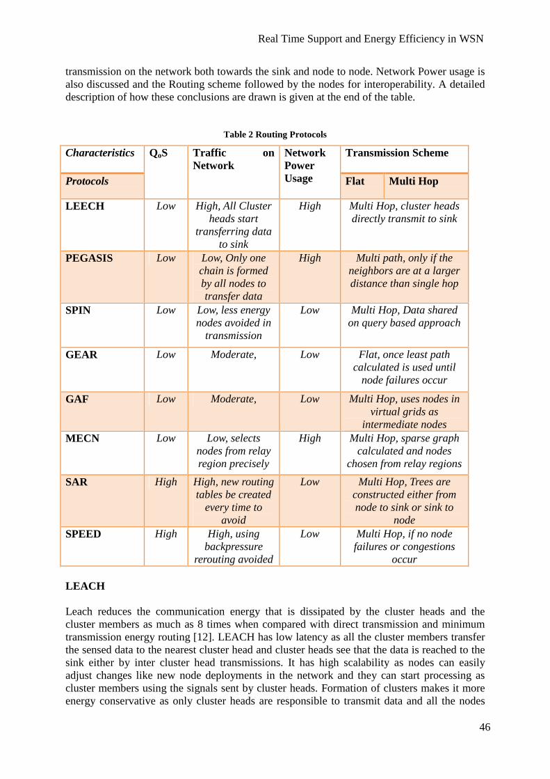
Real Time Support and Energy Efficiency in WSN
46
transmission on the network both towards the sink and node to node. Network Power usage is also discussed and the Routing scheme followed by the nodes for interoperability. A detailed description of how these conclusions are drawn is given at the end of the table.
Table 2 Routing Protocols
LEACH Leach reduces the communication energy that is dissipated by the cluster heads and the cluster members as much as 8 times when compared with direct transmission and minimum transmission energy routing [12]. LEACH has low latency as all the cluster members transfer the sensed data to the nearest cluster head and cluster heads see that the data is reached to the sink either by inter cluster head transmissions. It has high scalability as nodes can easily adjust changes like new node deployments in the network and they can start processing as cluster members using the signals sent by cluster heads. Formation of clusters makes it more energy conservative as only cluster heads are responsible to transmit data and all the nodes
Characteristics Transmission Scheme
Protocols
QoS
Traffic on Network
Network Power Usage Flat Multi Hop
LEECH Low High, All Cluster heads start
transferring data to sink
High Multi Hop, cluster heads directly transmit to sink
PEGASIS Low Low, Only one chain is formed by all nodes to transfer data
High Multi path, only if the neighbors are at a larger distance than single hop
SPIN Low Low, less energy nodes avoided in
transmission
Low Multi Hop, Data shared on query based approach
GEAR Low Moderate, Low Flat, once least path calculated is used until
node failures occur GAF Low Moderate, Low Multi Hop, uses nodes in
virtual grids as intermediate nodes
MECN Low Low, selects nodes from relay region precisely
High Multi Hop, sparse graph calculated and nodes
chosen from relay regions SAR High High, new routing
tables be created every time to
avoid
Low Multi Hop, Trees are constructed either from node to sink or sink to
node SPEED High High, using
backpressure rerouting avoided
Low Multi Hop, if no node failures or congestions
occur
Real Time Support and Energy Efficiency in WSN
47
follow randomised rotation to form cluster head. It has a low quality of service factor as it has resource limitations like limited processing which is done with very less memory buffer size. It has an unpredictable traffic pattern as all nodes in the network keep on changing the cluster regions. PEGASIS The chain formation in PEGASIS leads to a high latency as all the data has to pass through the chain to reach the base station, if the farthest or the first node of the chain has important information which has to be passed immediately will have to travel through the entire chain. It can easily add the newly deployed nodes in the chain as it is not a fixed transmitting path. If it finds a new node which saves much more energy it adds it during the chain formation. It has high energy awareness due to formation of chain structure to reach the base station which is much more energy conserving that cluster formation in LEACH. A low overhead is seen on the network as there are no other nodes which transmit other than all nodes that form the chain and only one node is responsible which is near to the destination or the sink to transmit. The quality of service factor is low as there is a delay in the data transmission and no processing capabilities, all nodes fuse some data with the data packet while forwarding to other nodes in the chain. Network instability like a node failure or link failure or power failure can cause loss of data. SPIN SPIN has moderate latency factor as it has to see that all ensures that all the interested nodes in the network achieve the required data. It has a moderate scalability because when ever a new node enters it sends signals or request for data sharing and all those nodes which are low in energy does not respond for any action to save energy, moderate energy awareness can be seen in SPIN as the nodes which are interested only take part in data sharing and the one which has low energy reserves stops responding to the messages sent by neighboring nodes. It has very low data overhead on the network as only few nodes take part in transmission. It keeps its quality of service factor low as there are redundant data in the network; all the nodes share the same data. Memory is wasted as all the nodes share same data, and it is not an end to end transmission many nodes interfere while transmitting the data to the sink or base station. GEAR GEAR has moderate energy efficiency as the nodes only follow the least cost paths that are calculated, until a new path is found which is much more least path than the earlier, this shows that even after using the least cost paths it fails in conserving more energy. It has a low latency as the time taken by a node to transmit between the source nodes to the destination region and from their to the destination node in the region. An average overhead is seen during transmission, if nodes find drained nodes in the network they stop data transmission until a new least cost path is found. The quality of service is low as it has certain network instabilities like link failure, power failure or topology changes can bring down data transmission. Lots of bandwidth is wasted in searching the destination region and then the destination node using different kinds of algorithms.
Real Time Support and Energy Efficiency in WSN
48
GAF Latency is moderate because when a source nodes wish to forward the data to the neighbour grid, all the nodes in that grid see that only one among them remain active to continue the forwarding strategy and the rest nodes go to sleep. It has a high scalability, any number of nodes can join the network and they divide themselves into grids and when there is more than one node, one of them goes to sleep to conserve energy. This makes it achieve high energy awareness as all the nodes changes states from active, discovery and sleep. As intermediate nodes are in sleep state, very few nodes take part in transmission gives low overhead of data in the network. It has very low quality of service factor as it has unpredictable traffic pattern, non end to end transmission prevails. MECN It has low scalability as if new nodes added to the sparse graph it does not consider them even though they are the nearest nodes to the base station. This also leads to low latency as each node has to calculate the sparse graph for its nearest neighbours every time it has data to transmit. Lot of energy is wasted in this sparse graph construction every time a node starts transmission. Even though its not considerable amount of energy it makes MECN a moderate energy aware protocol. A low quality of service factor is found as it has network instabilities like link failure, power failure, and limited bandwidth. SAR SAR has low latency factor as nodes always follows a routing table which shows a least cost path from the node to the sink, and there is for sure one path existing to the destination, QoS is more when compared with other conventional protocols, It has no resource limitations like limited bandwidth, transmission power, memory buffers. It has a limited scalability factor as it has to construct routing table for the newly deployed nodes which is costly. It has fault tolerance and easy node recovery for node failures. The power usage is very low and least compared because it constructs tree structure with only those nodes which are energy reserved and capable of QoS metric, the one which do not qualify are ignored from forming the roots in the tree. SPEED SPEED is one of the best routing protocols, it has low latency because all the nodes are directly connected so no delay in data transmission among nodes, even if there is a node failure using backpressure rerouting a new path is found to continue the data transmission process. It see the best possible paths with least cost which proves it be an energy conservative protocol. It always has low overhead because it balances the network in such a way that there are no congestions in the network, with a high quality of service factors like, no data redundancy, no resource limitations like limited processing, memory buffer size and even if link failure there back up for data transmission.

Real Time Support and Energy Efficiency in WSN
49
6. MAC (Medium Access Control) In wireless sensor networks, energy efficiency is the major issue and during communication different nodes send data at the same to the sink or base station so collision may occur and these packets can be corrupted and for retransmission energy is consumed. A properly designed MAC protocol allows the node to access the channel in a way to save energy and can support quality of service. A MAC protocol is normally based on one or several multiple access schemes like TDMA, CDMA, and FDMA (explained below).
6.1 Multiple Access Schemes Following are the paragraphs showing the Multiple Access Schemes used in WSNs.
6.1.1 TDMA The purpose of Time Division Multiple Access is to give time slot to the nodes so that different nodes can access the channel without collision. In WSNs, different nodes communicate with a base station or sink node. Using TDMA, a time slot is given to the node so that each node can send data to sink in that time slot and during the inactive slots nodes sleep to save energy. In this case, nodes can use full bandwidth during the time slot. In this scheme, clock synchronization is required to avoid collisions; therefore sinks have to broadcast the clock synchronization packet to all nodes while it has to receive the packet to avoid the collision. While receiving the packet it has to be reactive from sleep mode, as the active modes energy is consumed in this case.
6.1.2 FDMA In TDMA, each node has to be in active mode to receive the synchronization packet and might have extra communication delay caused by the time based access. FDMA avoids this problem by dividing the bandwidth in multiple channels so that each node can have its own channel to send the data without delaying. In FDMA nodes exchange their schedules in order to get synchronized.
6.1.3 CDMA Code Division Multiple Access is a technique in which different node use different codes in sending the packet and it provides the simultaneous transmission with slight interference. It overcomes the drawback of communication delay in TDMA and limited bandwidth in FDMA as it provides the full bandwidth to the nodes.
7. Carrier Sense Multiple Access (CSMA) In carrier sense multiple access, the nodes sense the channel. If the channel is free then they send the packet using full bandwidth. In this technique nodes lose a lot of energy because they keep sensing medium all the time. In dense network, the transmission suffers from frequent collisions and the communication delay increases. In the next section we will discuss protocols building upon the CSMA scheme.

Real Time Support and Energy Efficiency in WSN
50

Real Time Support and Energy Efficiency in WSN
51
8. Detailed Studies of MAC Protocols Now we will discuss about MAC protocols used in wireless sensor networks. A well designed MAC protocol can give energy efficiency and real time support to a wireless application. We will discuss how the protocols work, their features and their performance in a surveillance application.
8.1 Sensor-MAC (SMAC) Protocol In wireless sensor networks most important feature is the lifetime of the network which depends on the battery of a node and to make it energy efficient we need a suitable MAC protocol. There are different reasons due to which a node wastes a lot of energy like overhearing, idle listening and collisions. The SMAC protocol has an ability to overcome these factors that cause energy wastage. Ye, Heidemann, and Estrin [31] implemented the Sensor-MAC protocol on a Mote developed at University of California, Berkeley and they used the TinyOS platform. Tippanagoudar, Mahgoub, and Badi [58] implemented the SMAC protocol in the java based simulator JIST/SWANS and in NS2. Features of SMAC Following are the features of the SMAC protocol.
• Overhearing Avoidance • Collision Avoidance • Periodic Listening • Message Passing
Periodic Listening The SMAC protocol uses a periodic listening scheme to save energy, because due to idle state of a node, it wastes a lot of energy. In order to overcome the problem, the SMAC protocol puts the node in sleep state. If there is no event, then the node goes to sleep state and turns off the radio to save the energy. Listen Sleep Listen Sleep Time Fig: - 17 periodic listening scheme of SMAC protocol Figure 17 shows the periodic listening scheme of the SMAC protocol. Sleeping and listening times vary from application to application. Each node in a wireless sensor network has its own sleep and listening schedule but to reduce the control overhead, neighboring nodes synchronize together so that they sleep and listen at the same time [31].
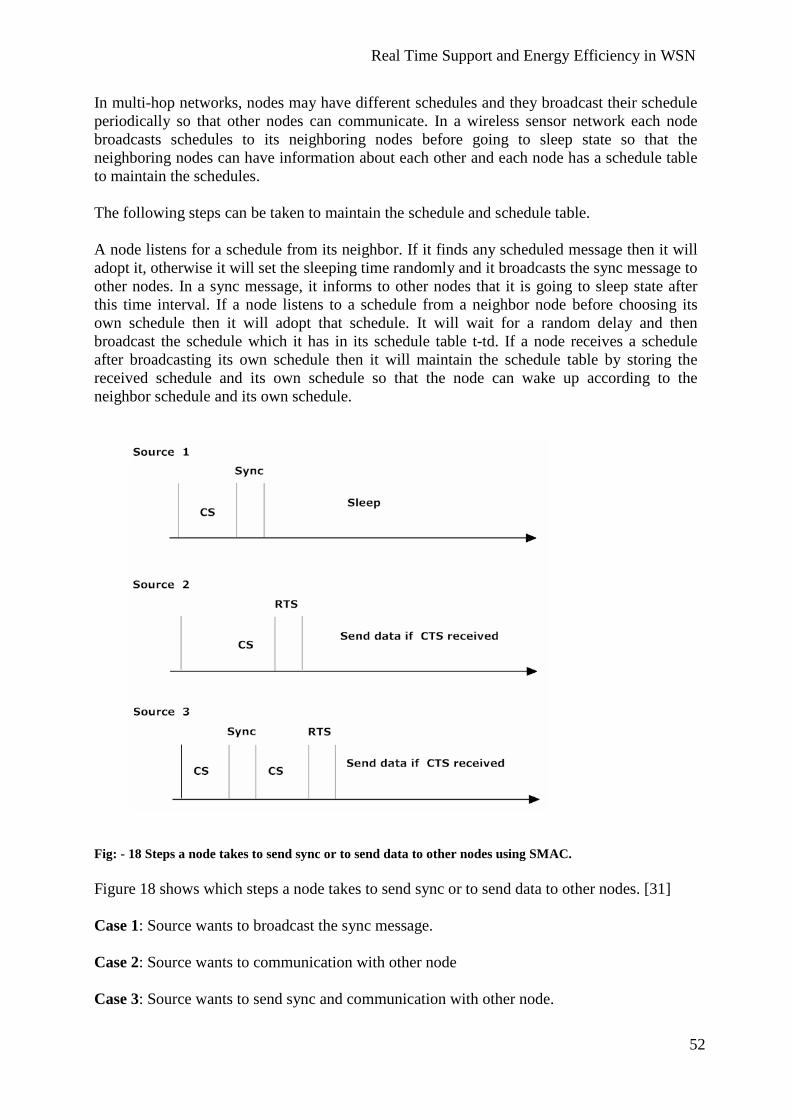
Real Time Support and Energy Efficiency in WSN
52
In multi-hop networks, nodes may have different schedules and they broadcast their schedule periodically so that other nodes can communicate. In a wireless sensor network each node broadcasts schedules to its neighboring nodes before going to sleep state so that the neighboring nodes can have information about each other and each node has a schedule table to maintain the schedules. The following steps can be taken to maintain the schedule and schedule table. A node listens for a schedule from its neighbor. If it finds any scheduled message then it will adopt it, otherwise it will set the sleeping time randomly and it broadcasts the sync message to other nodes. In a sync message, it informs to other nodes that it is going to sleep state after this time interval. If a node listens to a schedule from a neighbor node before choosing its own schedule then it will adopt that schedule. It will wait for a random delay and then broadcast the schedule which it has in its schedule table t-td. If a node receives a schedule after broadcasting its own schedule then it will maintain the schedule table by storing the received schedule and its own schedule so that the node can wake up according to the neighbor schedule and its own schedule. Fig: - 18 Steps a node takes to send sync or to send data to other nodes using SMAC. Figure 18 shows which steps a node takes to send sync or to send data to other nodes. [31] Case 1: Source wants to broadcast the sync message. Case 2: Source wants to communication with other node Case 3: Source wants to send sync and communication with other node.

Real Time Support and Energy Efficiency in WSN
53
In case 1, the Source wants to broadcast the sync packet which includes the Source address and the information about time to sleep. To do that first it will sense the medium for a moment. If it founds the medium free then it will stop carrier sensing and will broadcast the sync message. In case 2, the Source want to communicate with other nodes and for communication first it has to occupy the medium by sensing the medium. If it is free, the node will send the RTS (Request to Send) message to the other node and will wait for the CTS (Clear to Send) message from the destination node to establish the connection. After receiving the CTS message, the Source can transfer the data. In case 3, the Source wants to inform other nodes about its schedule and also wants to transfer the data. First it will start carrier sensing and send the sync message. After this it will again sense the medium either by using the medium or if it is free it gets a medium, then it starts sending the RTS message to the nodes for transferring the data and it will wait for CTS message from the destination end. Once it receives the CTS, it will start transferring the data. Collision Avoidance In a wireless sensor network multiple nodes can talk with a single node. If multiple nodes send messages at the same time, then there is a chance for collision to occur which causes a waste of energy. To overcome this problem, the SMAC protocol uses the physical and virtual carrier sense [32]. Whenever a node transmits a packet, it also includes the time duration of the transmission specifying how long it will communicate with other nodes. The purpose of this information is if any node receives a packet which is not intended for it, then it will keep quiet during the transmission. It will store this information in a variable called network allocation vector (NAV) [31]. It will set the timer with respect to the NAV value and when the NAV value becomes zero, the node will be able to transmit its data because the medium is free now. In physical carrier sense, each node senses the medium for a certain amount of time. If it finds the medium free, it starts transferring the data, otherwise it will go to the sleep state and sets the timer to awake itself so that it can start sensing the medium again. Overhearing Avoidance Overhearing also consumes a lot of energy because a node receives a message which is not intended or destined for it. In the SMAC protocol, whenever a node receives a packet which is not for it, then the node receives a control message and goes to sleep state until the transmission completes. A control packet is smaller than the data packet and if a node keeps listening to the data packet on the medium it uses a lot of energy though it is not the appropriate destination to receive the data packet. SMAC lets the node listen to the control packet and send it into sleep state; the node set its timer with respect to NAV value to awake itself. Adaptive Listening The SMAC protocol saves energy by putting the node in sleep state periodically but due to periodic sleeping, latency increases in multi-hop networks, when there is information that has to be passed on the network. SMAC uses the adaptive listening technique to decrease the

Real Time Support and Energy Efficiency in WSN
54
latency. It wakes up the nodes which overhear the packet at the end of a transmission using to the control packet they received as described above. The node will not need to wait listening to the schedule of the neighbor node and it can send the message immediately. If there is no information during the adaptive listening then the node will go into sleep state. [32] Message Passing In a wireless sensor network a message contains information about an event that occurred. The message can be small or long, usually long messages increase the latency and can also waste the energy. If the few bits are corrupted in first transmission then a retransmission is done due to which lots of energy is consumed. A long message can be divided into small packets but for transmission of each packet control packet is needed and due to control packet for each small packet transmission delay will be increased. The SMAC protocol divides the long packet into small fragments and sends them in burst. SMAC uses only one packet for RTS and CTS for the whole transmission. In this situation when a packet is sent, the Source waits for the ACK and if it gets the ACK packet it transfers the next fragment. On the other hand, if it does not get any ACK it increases the transmissions time by one fragment and retransmit that fragment. The current transmission can be corrupted at the Source end if the Source does not get an ACK from the destination. If an existing node wakes up during the transmission process, it can start using the medium if it finds it free. This may lead to disturbance in the transmission at the destination side. To avoid this, each packet contains the field for transmission duration. If a new node joins the network during the transmission, after receiving the RTS or CTS packet it will go to sleep state and when it wakes up, it will be able to get information about extended period of time if there is a packet loss. Protocol Performance in surveillance applications SMAC protocol reduces the energy consumption through overhearing, avoidance and message passing. It also makes the node energy efficient through periodic listening and sleeping scheme. If we look at SMAC with respect to surveillance applications, then it will be suitable when the network structure is static and there is a constant data rate because it uses the constant duty cycle and if there is a variation in the traffic then most of the energy of the node will be wasted in the idle state. [33]
8.2 Timeout-MAC (TMAC) Protocol In wireless sensor networks, idle listening wastes lots of energy of a node. The SMAC protocol tries to reduce the idle listening time through a periodic sleeping / listening scheme. If there is dynamic traffic, then there are some chances of idle states in SMAC, for example if there is a small message which takes 10 seconds to transmit and receive. SMAC uses around 20 seconds to receive and transmits the message. This is actually referred as active time which will be 10 seconds and its idle time will be 10 seconds. It means, it is wasting 50% of energy by idle listening. To overcome this problem, The TMAC protocol introduces the time out scheme in which a threshold value is defined and if a node does not hear anything within the duration of the threshold value then it will go to sleep state. Langendoen [34] carried out simulations of the TMAC protocol in OMNeT++, which is a C++-based discrete event simulation package developed at the Technical University of Budapest and then they implemented this protocol on the EYES hardware.

Real Time Support and Energy Efficiency in WSN
55
SMAC
TX I RX I
A S A S TIME TMAC TX TA RX TA A S A S TIME Fig:- 19 the comparison between SMAC and TMAC duty cycles S = SLEEP, A = ACTIVE, I = IDLE Figure 19 shows the comparison between SMAC and TMAC duty cycles. We can see that SMAC uses the constant sleeping/listening time while TMAC’s listening and sleeping time changes according to the traffic. In SMAC, a node uses less active time if there is variation in messages rate and the rest of the time, the node stays in idle state. On the other hand, TMAC active time varies with message rate. It uses the time-out value to reduce the idle listening. Overhearing Like SMAC, TMAC also uses a control packet to avoid overhearing. A node will only listen to the control packet and will go to sleep state and set the timer to awake itself according to the information in the control packet. Control packets are smaller than data packets and contain information about how long the transmission will continue so that other nodes remain in sleep state during this transmission. Synchronization Synchronization is important to increase the performance of the network. TMAC uses the SMAC synchronization scheme in which a group of nodes makes a virtual cluster and for synchronization each node broadcasts the sync packet in the network which contains a schedule of the node, so that other nodes can know when it will go to sleep state. Due to the early sleeping problem, synchronization of listening period can be broken [35]. TMAC gives two solutions to solve the early sleeping problem in which a destination goes to sleep state while the Source has data to send.
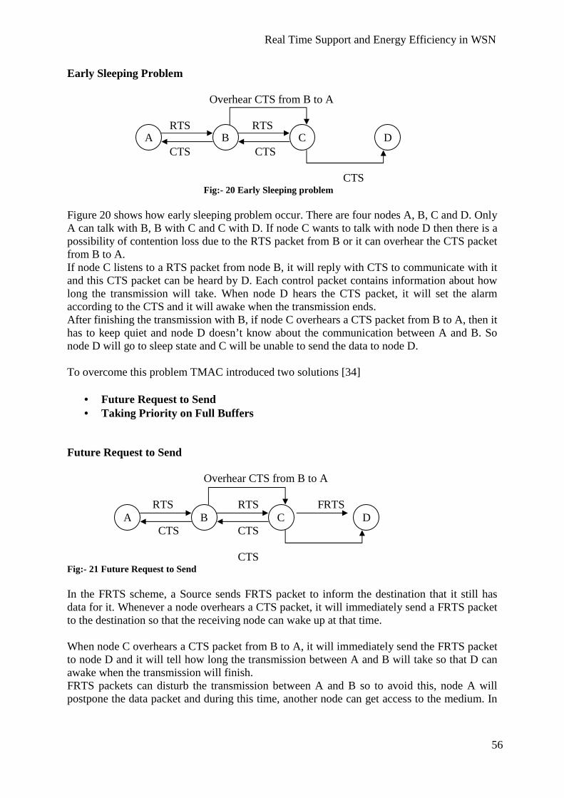
Real Time Support and Energy Efficiency in WSN
56
A B C D
A B C D
Early Sleeping Problem Overhear CTS from B to A
RTS RTS CTS CTS
CTS Fig:- 20 Early Sleeping problem
Figure 20 shows how early sleeping problem occur. There are four nodes A, B, C and D. Only A can talk with B, B with C and C with D. If node C wants to talk with node D then there is a possibility of contention loss due to the RTS packet from B or it can overhear the CTS packet from B to A. If node C listens to a RTS packet from node B, it will reply with CTS to communicate with it and this CTS packet can be heard by D. Each control packet contains information about how long the transmission will take. When node D hears the CTS packet, it will set the alarm according to the CTS and it will awake when the transmission ends. After finishing the transmission with B, if node C overhears a CTS packet from B to A, then it has to keep quiet and node D doesn’t know about the communication between A and B. So node D will go to sleep state and C will be unable to send the data to node D. To overcome this problem TMAC introduced two solutions [34]
• Future Request to Send • Taking Priority on Full Buffers
Future Request to Send
Overhear CTS from B to A RTS RTS FRTS CTS CTS CTS Fig:- 21 Future Request to Send In the FRTS scheme, a Source sends FRTS packet to inform the destination that it still has data for it. Whenever a node overhears a CTS packet, it will immediately send a FRTS packet to the destination so that the receiving node can wake up at that time. When node C overhears a CTS packet from B to A, it will immediately send the FRTS packet to node D and it will tell how long the transmission between A and B will take so that D can awake when the transmission will finish. FRTS packets can disturb the transmission between A and B so to avoid this, node A will postpone the data packet and during this time, another node can get access to the medium. In

Real Time Support and Energy Efficiency in WSN
57
order to hold the medium, node A will send the Data Send (DS) packet and after the DS packet it will send the data packet. Taking Priority on Full Buffers Taking priority on full buffers is another scheme to overcome the early sleeping problem. In this scheme, when a node buffer (memory containing routing information) is full then it will prefer sending to receiving. Whenever a node receives a RTS packet which is destined for it and if its buffer is full, then it will immediately send its own RTS packet instead of replying with a CTS packet. In this situation, the node has higher chances of getting access to the medium. On the other hand the transmission flow will be limited. The taking priority on full buffers scheme is good for node to sink or node to node communication. It is not good for omni directional communication where traffic load is high and due to limited flow, latency can be increased. TMAC uses this scheme only when node looses access to the medium two times. Protocol Performance in surveillance applications The TMAC protocol is an improvement of SMAC and it handle the situation of varying traffic using time-out values. Synchronization is the same as in SMAC and it handles the early sleeping problem by sending FRTS packet and a buffer priority scheme. In surveillance applications, nodes are scattered in large areas and to process an event or send it to a sink, multi-hop communication is required. TMAC has an advantage over SMAC because it reduces the latency through Future Request To Send. But in heavy traffic TMAC suffers from high latency and limited throughput. [36]
7.3 Sparse Topology and Energy Management (STEM) Most of the applications in wireless sensor networks (like surveillance, monitoring, battlefield application etc) require fast forwarding of data. These applications consist of large networks, containing large numbers of nodes. Whenever a node senses an event it should forward the data towards the sink. Each node within the area where the event occurred should participate in forwarding the information to sink so that the end user can see the event occurrence in a specific area. On the other hand, each node should be energy efficient to prolong the life of the network and for this purpose each node should turn off the radio periodically or when there is no event to sense. STEM is an event triggered protocol used for applications where nodes spend most of the time in waiting for an event. If any event occurs then it forwards the data to the desired nodes. In a wireless sensor network a node spends huge part of energy sensing an event and forwarding it into the network refers as transferring state. STEM reduces the energy in monitoring state and reduces the latency between monitoring and transferring states. In the work reported in [37], the authors used the Parse platform (A parallel simulation environment for complex system) to simulate STEM. Parse is an event-driven parallel simulation language. Coordination among Nodes To trace an event and forward it to the sink node, all nodes must be synchronized. In event triggered networks, most of the time nodes remain in monitoring state and waste lots of

Real Time Support and Energy Efficiency in WSN
58
A B
energy. There are two topology management techniques, SPAN and GAF, introduced in [38] and shortly described below. SPAN SPAN is a technique which is used in multi hop networks to save energy. The idea of span is that when a specific number of nodes are sharing a channel, then only a small number of nodes can forward data. SPAN allows the nodes to make local decisions on the basis of the energy it has and it is helpful for others nodes if it stays awake or to sleep. In SPAN, the lifetime of a network is based on the idle-to-sleep relation and the density of the network. If the relation between idle and sleep time and the density of the network increases, then the lifetime of the network will also increase. GAF In the Geographic Adaptive Fidelity approach, the sensor network is divided into grids and the grid size is constant, it does not depend on the density of nodes in the network. In each grid, only one node remains active and the rest of the nodes remain in sleep state. Working of STEM STEM uses two radios to save energy of a wireless sensor network. One is a data radio and the other is a wake up radio. The wake up radio lets the data radio remain in sleep state until it finds an event to transfer or to operate. The wake up radio uses a low duty cycle and it periodically listens for events. If there is any event which has to be processed, then it activates the data radio. There is another technique to save the energy by putting the one part of the radio in sleep state while second part in monitoring state [39]. Instead of heaving two radios one radio can be used and switch between the wake up and transfer state using different frequencies. This can lead to a problem if a target node transferring data wishes to wakeup another node. It has to postpone the current information and latency will increase. If a node away from sink and it sensed an event which is not sensed by the node near to sink. It cannot forward the information to sink because the next node is in sleep state. To handle this kind of situation, STEM lets the nodes turn on their radio periodically and listen if any node wants to communicate with them.
f 1 wake up f 2 Data Fig:- 22 STEM Figure 22 shows the idea of STEM, in which two radios are used having frequency f1 and f2. Suppose node A sensed an event and it wants to transfer the information to node B. Then it will send a signal called beacon to wake up the node B and it will wait for the acknowledgment from B and the time interval of connection between node A and B is sufficient to send and receive the acknowledgment. After receiving the acknowledgment from node B, node A will transfer the data and both node A and B will keep their radios on until they finish the communication. In STEM, nodes also turn their data radios on to avoid the collision of beacons and if the node hears any collision then it will not respond. If any node

Real Time Support and Energy Efficiency in WSN
59
awakes due to the collision and it is not the targeted node, it will turn on its data radio and wait for a short time. If it does not find any data, it will turn off its data radio and will go to monitoring state. STEM and GAF STEM is useful for event triggered applications where nodes are scattered. The combination of GAF and STEM will work fine in this situation with combining the grid feature of GAF and connection setup feature of STEM. GAF saves energy by dividing the network into grids and then selecting a node as a leader. The leader remains active while the rest of nodes in the grid remain in sleep state. In the leader selection process, every node will start a discovery process to become a leader. The node that has more energy than others will be elected as a leader and it will perform functions like data aggregation and routing [53]. In the combination of STEM and GAF, a leader will perform STEM operations. To avoid multiple leaders in a grid, if a node wants to be a leader, it has to setup a connection with an existing leader using STEM. [37] Protocol Performance in surveillance applications Sparse Topology and Energy Management is an efficient technique in energy saving specially in surveillance application where hundreds of nodes are placed in the area and waiting for an event to transfer. The combination of GAF and STEM is good approach for large network where it is needed to subdivide the network into small grids to increase the performance of the network. It is a good technique for energy saving and to reduce the setup latency between nodes which helps in build up faster communication paths. The data can be transferred between nodes with short delay which shows its real time support for event triggered data transfer through the network, but on the other hand it is expensive to have two radio which increase the overall network cost. It also consumes some amount of energy to wake up the data radio.
8.4 Traffic Aware Energy Efficient MAC Traffic Aware Energy Efficient MAC uses the same technique to save the energy as used in SMAC but instead of fixed duty cycle, it makes the duty cycle adaptive according to the traffic information. Due to the fixed duty cycle when using the SMAC protocol, a node consumes energy when there is nothing to process because it has to stay in its listen state. In SMAC, a node uses control messages for communication. For synchronization, SMAC uses sync messages and each node can send or receive the sync packet in its listen period. The neighboring nodes form virtual clusters and in each cluster all nodes have the same schedule which reduces the latency. If a node wants to communicate with other nodes, then it has to send a RTS packet and the destination will response with CTS packet. After receiving the CTS packet, the Source can send the data and both nodes should active until the communication is finished. [31] The TMAC protocol follows the SMAC scheme and the energy consumption is same at a constant message rate while it shows better result than SMAC when there is variation in messages rate. In TMAC, each node tries to transmit its queued packet at the beginning of each frame with maximum rate to win the medium. If a node losses a contention it should go to sleep state and wait the entire frame which may cause energy waste, low throughput and increased latency. [40]
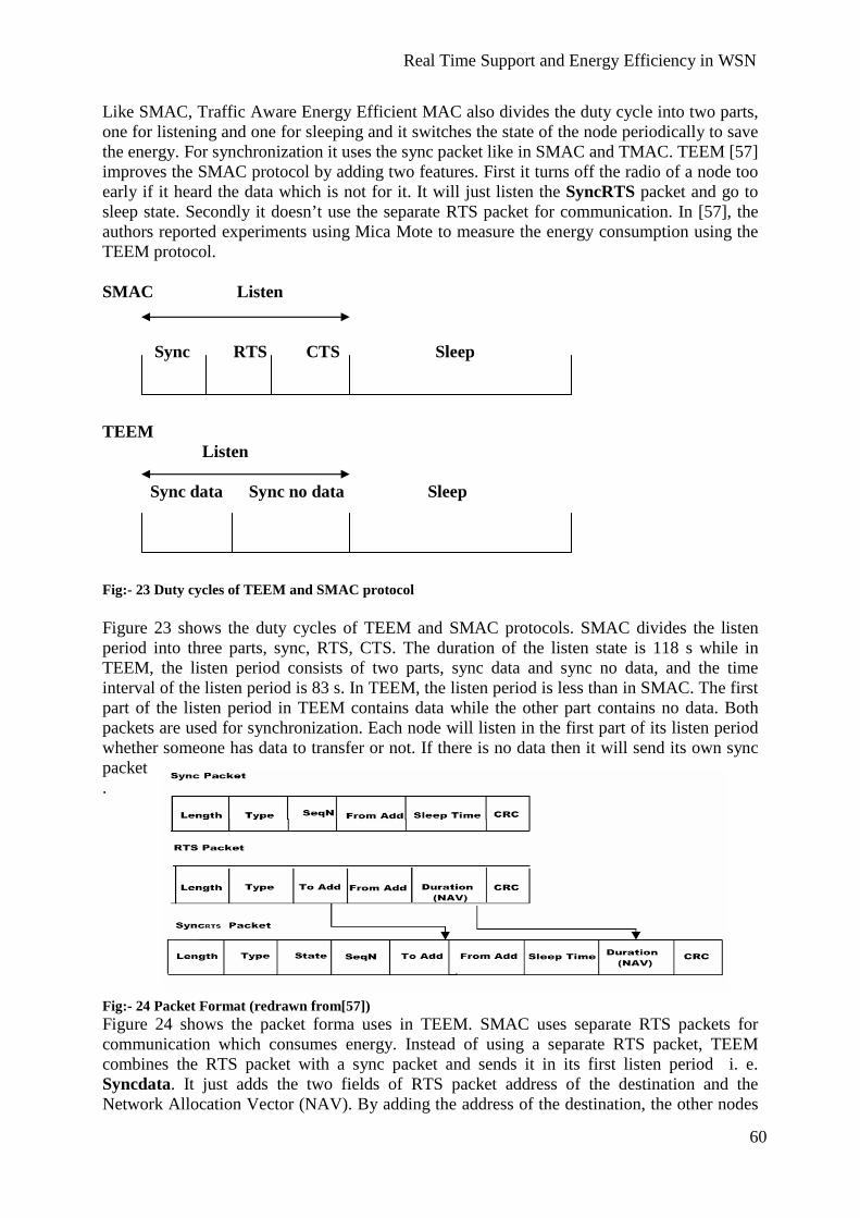
Real Time Support and Energy Efficiency in WSN
60
Like SMAC, Traffic Aware Energy Efficient MAC also divides the duty cycle into two parts, one for listening and one for sleeping and it switches the state of the node periodically to save the energy. For synchronization it uses the sync packet like in SMAC and TMAC. TEEM [57] improves the SMAC protocol by adding two features. First it turns off the radio of a node too early if it heard the data which is not for it. It will just listen the SyncRTS packet and go to sleep state. Secondly it doesn’t use the separate RTS packet for communication. In [57], the authors reported experiments using Mica Mote to measure the energy consumption using the TEEM protocol. SMAC Listen
Sync RTS CTS Sleep
TEEM Listen
Sync data Sync no data Sleep Fig:- 23 Duty cycles of TEEM and SMAC protocol Figure 23 shows the duty cycles of TEEM and SMAC protocols. SMAC divides the listen period into three parts, sync, RTS, CTS. The duration of the listen state is 118 s while in TEEM, the listen period consists of two parts, sync data and sync no data, and the time interval of the listen period is 83 s. In TEEM, the listen period is less than in SMAC. The first part of the listen period in TEEM contains data while the other part contains no data. Both packets are used for synchronization. Each node will listen in the first part of its listen period whether someone has data to transfer or not. If there is no data then it will send its own sync packet. Fig:- 24 Packet Format (redrawn from[57]) Figure 24 shows the packet forma uses in TEEM. SMAC uses separate RTS packets for communication which consumes energy. Instead of using a separate RTS packet, TEEM combines the RTS packet with a sync packet and sends it in its first listen period i. e. Syncdata. It just adds the two fields of RTS packet address of the destination and the Network Allocation Vector (NAV). By adding the address of the destination, the other nodes

Real Time Support and Energy Efficiency in WSN
61
can see who should receive the data and the Network Allocation Vector describes the duration of the communication. When a Source broadcasts the sync packet, the nodes will update their timer according to the NAV for synchronization. The combination of sync packet and RTS is named as SyncRTS. Whenever a node wants to communicate with other node it will send the SyncRTS packet in its sync data part. SMAC TEEM Fig:- 25 Fixed Duty Cycle vs Adaptive Duty Cycle (redrawn from[R.57]) From figure 25 we can see the difference between the duty cycles of TEEM and SMAC. In SMAC nodes stay alive in their entire listen period and they can sleep for a very short period. If we look at the figure of SMAC, whenever node A wants to communicate with node B, it will broadcast the sync packet. This packet can be heard by all nodes. After sending the sync packet, node A will send the RTS (Request To Send) and node B will reply with CTS (Clear To Send) packet but other nodes can also receive these packet because they are still in listen period. After exchange of RTS and CTS packets, both nodes will be in active state until they finish the communication. On the other hand, if no node has data to transfer, they will just broadcast the sync packet so that other nodes can synchronize according to their schedule like discussed in [R.31]. In this state, when there is no data to transfer or receive, the nodes waste energy which affects the entire lifetime of the network. TEEM reduces the size of the listen period by combining the sync packet and RTS packet in SyncRTS packet. When a node A wants to communicate with node B it will send SyncRTS packets instead of a separate RTS packet. Each SyncRTS packet has information of the

Real Time Support and Energy Efficiency in WSN
62
Source, destination and duration of the communication. The destination node B will reply with a CTS packet and then node A will transfer the data. After receiving the data packet, node B will send the ACK packet to node A which confirmed that B has received data successfully. This SyncRTS packet can be picked up by other nodes like in SMAC, but TEEM lets the nodes in sleep state after receiving the SyncRTS packet in their first period of listen interval i.e. Syncdata. As a consequence, the undestined nodes will get longer sleep time as compared to SMAC. If no node has data in its queue, nodes will wait for data in their first part of the listen period, i.e. Syncdata. If they found no data then they will broadcast the “sync no data” packet. And after receiving or transferring the “sync no data” packet node will go into the sleep state. Protocol Performance in surveillance applications Traffic-Aware Energy Efficient MAC is better with respect to energy efficiency than other contention-based protocols like SMAC and TMAC because it gives more sleeping time to a node. If we apply this protocol in surveillance application, it will not work well because it only provides one hop forwarding per transmission slot. On the other hand, single-hop communication is good if the network is small.
8.5 Distributed Energy Aware MAC Protocol In wireless sensor networks, energy management is a critical issue: energy can be wasted in the form of collision, overhearing or idle listening. Contention-based MAC protocols give the solutions of energy management in term of periodic sleep/listening. Some of them use constant duty cycle, while some use adaptive duty cycle to reduce the idle listening. For collision avoidance they use control packet. Overhearing can be avoided by putting the radio off after receiving the un-destined packet. The most common and easiest way to implement a MAC protocol is IEEE 802.11, which reduces the amount of collisions by way of control packets. It uses the CSMA/CA technique to access the medium. It is not an energy-efficient protocol because it does not handle the situation of overhearing and idle listening. PAMAS (Power-aware Multiaccess with Signaling) [52] reduces the energy by using an out-of-channel signaling. It uses two channels: one for communication and the other for probes. Energy can be wasted due to the collision of probe messages. SMAC is the improvement of PAMAS and it reduces the energy of nodes using periodic sleep/listening method. It avoids overhearing by turning off the radio of the nodes if they receive the undestined packet. The node will only receive the control packet and it will set the timer according to the NAV value specified in the control packet. Due to possible collisions of RTS and CTS, packet energy can be wasted. It also specifies the constant sleep and listen period for a node, which is not good, as it has the least energy ratio compared to other nodes [42],[31]. The Distributed Energy Aware MAC [43] protocol is a contention free protocol. It uses a TDMA scheme in which every node has pre-assigned time slots through which it can transfer the data. A node knows its neighbor’s time slots, so it will remain in wake-up state even though its neighbor node has data to transfer or nothing to send. In DEMAC, every node has to use its own time slot to transfer the data so as to avoid collision. DEMAC treats the nodes with respect to their energy level and it gives more time to a node which has less energy than

Real Time Support and Energy Efficiency in WSN
63
other nodes. To save energy, it uses the periodic scheme and if there is no data to transfer node will sleep. DEMAC conducts an election periodically and all nodes will participate in the election. Every node will send the energy-level messages which is sent with scheduled transmission packet within their scheduled time slot. So there is no extra time slot used for the energy level packet. If the node’s energy level decreases below a threshold value, it will go into the election phase and it will send the energy level packet to all its neighbors. By their vote, it will check whether its energy is lower than the others’ energy or not. If its energy is lower than the others energy, it will be the winner node and it will increase its time slots so it can sleep. The other nodes are stated as losers and will decrease their time slots. The winner node will also send its energy-level packet after the election. The authors used SensorSim to simulate the DEMAC, where SensorSim is an extension of the NS-2 simulator [43]. In the DEMAC protocol, the following types of packets are used in the data transfer and the election procedure:
� Data Packets � Control Packets
Data Packets: Data packets are the normal packets which contain information of a specific event and transfer them to the base station. Control Packets: These packets contain information about the type of packet and the attribute it has, like transmission time, addressed etc. Control packets are further divided into two categories.
� Vote Packet � Radio Power Mode Packet
Vote Packet: A node uses this packet when it enters into election phase. It indicates the information about the energy level of nodes. The leader or winner nodes depend on this information. Radio Power Mode Packet: This packet indicates that the Source is using one slot or two slots for data transmission. Each node knows when it should wake up to receive data, as it has destination table which indicate the source address and the slot number. Nodes uses the extra-state variable Radio-Power-Mode to maintain the information regarding its neighbor, so it sets the radio mode in receiving state if its neighbor has data to send. Phases of Node: A node can be in two phases:

Real Time Support and Energy Efficiency in WSN
64
� Normal Operation Phase � Vote Phase
In normal-operation phase, a node sends the data packet in its own time slot and if it does not have anything to transfer, it will go into sleep state. It has to wake up during the time slots of its neighbor so that it can receive the data. On the other hand, a node enters in the vote phase when its energy becomes less than a threshold value. Vote Phase Operation
Fig:- 26 vote operation phase of a node Figure 26 shows the vote-operation phase of a node. Whenever a node energy EN become less than a threshold value TA, it will send the energy level packet to other nodes N[i]. Then each node will process the packet and see if its energy is less than that specific node. After processing the packet, it will send the vote negative or positive to that node. After receiving the energy level packet from other nodes, it will decide whether it will become a looser or a winner. From the figure above we can see that when there is a positive vote the radio mode is set as true and then the node sets other nodes with its energy levels and the radio mode for

Real Time Support and Energy Efficiency in WSN
65
further operation. If it gets a negative vote, it will set the radio mode false and the number of time slot will decrease. [57] Normal Operation Phase
Fig:- 26 vote operation phase of a node Figure 27 describes the normal operation phase of a node. As we have discussed above, in DEMAC, each node has pre-assigned time slots and it has to transfer the data in these slots. In normal-operation phase, each node has to decide whether it will sleep or send data in its time slot. If a node has data in its time slot, it will send the data to the destination and both nodes’ radio must be in receiving mode. If the node does not have data to transfer in its own slot, it will go into sleep state. On the other hand, a node uses the local state variable to check the radio of neighbor nodes. It will check the time slot of its neighbor nodes to find out whether they use time slots or not. If they have data, it will put the radio in receiving mode, otherwise it will turn off the radio. Protocol Performance in surveillance applications Distributed Energy Aware MAC protocol is a TDMA-based protocol. If we look at this protocol from a surveillance point of view, it will give better quality of service than contention-based protocols. It provides collision-free communication because each node has pre-assigned time slots. DEMAC uses an election process which can increase the energy

Real Time Support and Energy Efficiency in WSN
66
consumption and latency in heavy traffic. It also increases the energy consumption of a node because it has to listen in its neighboring time slots. It can only sleep in its own time slots.
8.6 Power Aware Cluster TDMA (PACT) In wireless sensor network applications like surveillance, a large number of nodes are placed to detect an event where the typical communication between the nodes is multi-hop. PACT is a TDMA-based protocol used for large multi-hop wireless sensor networks. PACT uses adaptive duty cycle with respect to traffic. It turns the radio off if there is no traffic in the network. It uses the passive clustering to save the energy in which small number of nodes participated in the communication are called cluster heads and gateways. These nodes are elected with respect to their energy level and it eliminates the need to send a separate packet defining the energy level. The authors of [45] simulated the PACT protocol in GlomoSim. The GlomoSim provides fast simulation of large network. Features of PACT The following are the features of Power Aware Clustered TDMA [45].
� PACT uses passive clustering in which one node act as a communication backbone within a cluster.
� It selects nodes as gateways which are members of one or more clusters, where
communication between the cluster heads is possible.
� PACT selects nodes as cluster heads and gateways based on their energy level.
� PACT uses adaptive duty cycle with respect to traffic and it turns off the radio of the nodes during inactive period or when there is no traffic to transmit.
� It uses a simple scheme to select the active gateways between neighboring cluster
heads. PACT considers both the space and time domain to minimize the energy consumption and communication cost. In the space domain, PACT uses the passive clustering structure to minimize the communication cost, while it saves the energy by allowing the nodes to use only active slots and sleep during in inactive slots [45]. Passive Clustering In large multi-hop wireless networks clustering and partitioning are common techniques to prolong network life. To select the cluster head in a cluster, each node sends a separate energy level packet. But in passive clustering as described in [46], it eliminates the use of separate energy level packets.

Real Time Support and Energy Efficiency in WSN
67
Fig:-28 Passive Clustering Figure 28 [47] show the concept of passive clustering in which each circle shows an isolated cluster. Each cluster contains cluster-head gateway and cluster members. The nodes exchange their energy level by adding two extra bits in every message [48]. Cluster heads are selected based on their energy levels. The nodes that are members of more than one cluster are called Gateways, which allows clusters heads to communicate among themselves. These cluster heads and gateways forward the traffic in the entire network. In [48], the authors describe the low energy state (LES) of cluster heads and gateway nodes. When the energy level of cluster heads and gateways become less than the threshold level, they change their state to LES. A node in the LES state will not act as a cluster head or gateway until it is recharged, but it can participate as a cluster member. Each node exchanges the information of cluster heads ID using a control packet and this information limits the number of gateways between the cluster heads. If there are multiple gateways, the node with the highest number of IDs will be selected as a gateway and the rest of the gateways will preserve their energy for future use. . Slot Assignment Schemes There are two common slot-assignment schemes used:
� Node Activation � Link Activation
In the node-activation scheme, each node uses a single time slot to transmit the information to a number of nodes. While in the link-activation scheme, a node can transmit a packet to its neighbor only. In link activation, a node sends a separate broadcast message to its neighbors. Node activation is suitable for those applications where the network is large and with a low traffic load. In PACT, each frame consists of control slots and data slots. Each node uses a control slot to inform other nodes about its data slots and during each control slot all nodes will turn on their radio. Control slots remove the transmission conflict among nodes because every node can know about transmission or data slots of its neighboring nodes through the control information. The member nodes will give priority to the cluster heads and gateways in slot selection while in each control packet, the node will specify the destination address so that the destination node can turn on its radio and other nodes can turn off their radio during inactive slots.

Real Time Support and Energy Efficiency in WSN
68
Protocol Performance in surveillance applications The PACT protocol is a TDMA-based protocol in which each node has pre-assigned time slots to provide collision-free communication. If we look at this protocol with respect to surveillance application, it will give better results because it provides collision-free communication. It uses the passive clustering technique to make nodes energy efficient by only allowing gateways and cluster head nodes to participate in data forwarding. On the other hand, each node has to listen to the mini slots or control packets from other nodes in order to get the control information. This may lead to some energy consumption.
8.7 A Lightweight Medium Access Protocol (LMAC) Wireless sensor nodes consist of RF Transceiver, which allows it to receive or transfer the signal. During sleep state the transceiver of the nodes turn off their oscillators to save energy. When nodes change their state from sleep to listen, the transceiver turns on their oscillator in order to receive the signal. The oscillator takes time to restart which causes it to utilize some amount of energy. If this process happens frequently it may effect the network life time. The switching states of transceiver must be minimized or it should be traffic adaptive to prolong the network lifetime. [49] The purpose of MAC protocols is to minimize the energy consumption by decreasing the collision probability, overhearing and idle listening, and to provide effective communication using limited latency and data loss. LMAC is TDMA-based protocol which tries to minimize the transceiver switches and make the switching-state traffic adaptive. It allows the nodes to sleep when there is no data to transfer. The LMAC protocol is based on Eyes Medium Access Protocol (EMAC) described in [49]. The EMAC protocol is a TDMA based protocol in which each node has one slot to transmit the data in a frame and it can reserve the slot in the next frame. It divides the frame into three parts: Communication Request (CR), Traffic Control (TC) and data section. In [49], the authors uses OMNet++ simulator to simulate the LMAC protocol. Fig:- 29 Frame Format (redrawn from [50]) Figure 29 shows the frame format used in the EMAC protocol. Each node has one slot in the frame to control the slot. In the CR part, nodes can send a request for data, such as the RTS message in SMAC, to the node which is owner of the time slot. In TC part, the owner of the slot sends the control information about the data which is sent in the form of address, type of packet etc. After the TC part, the data unit is transferred. Similarly to EMAC, the LMAC also allows the nodes one time slot in a frame. And they can get a chance to reserve the slot in the next frame. In the LMAC protocol, a time slot is divided into two parts.

Real Time Support and Energy Efficiency in WSN
69
� Control Message � Data Message
Fig:- 30 Frame Format (redrawn from [51]) Figure 30 shows the TDMA-Frame format of the LMAC protocol in which each time slot is divided into two parts: control message and data message. Control Message The control message is a fixed sized packet and it carries control information like control id, current slot number, distance to the gateway, data length, destination address, occupied slots, collision in the slot (further information on the control packet can be found in [21]) A control packet is also used for synchronization. Each node has to listen to the control packet from its neighboring nodes. Data Message The data message has information about the destination nodes. Both source and destination will keep their radio on until they finish the communication. The source node will send the control message including the destination address before sending the data message. If there are multiple destinations, all destination nodes will keep their radio on to receive the data message after receiving the control message. If both source and destination nodes have finished their communication before the expiration of the time slot, they will turn off their radio to avoid idle listening. The LMAC uses a distributed algorithm to find free slots. The LMAC protocol allows the node to select the slot that is not in use within two-hop neighboring nodes. The new node selects the time slot before sending data. It has to listen all control messages in a complete frame to find a free slot, as each control message has information about the time slot it contains. The new node will operate ‘OR’ to all received occupied slots and then it can find which time slots those are free. [50] Network Setup In order to make the network setup perfect all nodes should be synchronized. In SMAC [31] and TMAC [34] the nodes wait for some time to listen to the schedule from other nodes. If it does not hear anything, it will select its own schedule and broadcast it. In LMAC, a gateway starts controlling the time slot and sends the control message to its neighbors. All neighbors within one-hop will synchronize with that control message and will get information about the time slot after listening to the complete frame. Each node contains the neighbor table to

Real Time Support and Energy Efficiency in WSN
70
maintain the information about its neighboring nodes and which slots are occupied. A node can control the slot when it is not used by its neighbors and a collision-free communication is ensured. It is possible that two nodes can select the same time slot to control it and this may lead to a collision between the control messages. The collision can be detected by the neighboring nodes which will inform the node that their control messages have collided. After getting this information they will stop controlling and will wait for a free time slot. Routing For efficient routing, each node in the network will keep the hop-distance to its designated gateway node. It will broadcast this information in its control message. The other nodes will receive control message and update their neighbor table, if the distance to the gateway is smaller than the value which they have in the neighbor table. If the node has multiple-neighbor nodes which are closer to the gateway it will randomly select one among these to forward the data. Protocol Performance in surveillance applications Lightweight Medium Access Protocol (LMAC) is a contention-free protocol. It uses a clustering scheme to handle multi-hop communication. Like EMAC, it gives one time slot to each node to control it. It provides collision-free communication by ensuring that no node can select the same time slot which is in use by its neighbors within two-hop distance. If we apply this protocol in surveillance application, it will not work better because each node has to wait for its time slot which increase the latency and give limited throughput. On the other side each node has to listen in the control section of each frame which may lead to the waste of energy.

Real Time Support and Energy Efficiency in WSN
71
9. Comparison of MAC Protocols The following chart shows the comparison of different MAC protocols according to the surveillance application with assumptions like energy awareness, QoS and latency etc. From the comparison table, one can see which protocol is better in which situation, e.g. in which situation a protocol is more energy aware, provides high QoS and low latency or whether a protocol uses a control packet for communication or not and which MAC scheme it uses to access the medium or whether synchronization is needed or not. A description of how the values are retrieved for the protocols into the table is described below.
Table- 3 MAC Protocols
Characteristics Energy Awareness
Synchronization
Protocols Low
Moderate
High
Contention based or contention free
Quality of Service
Required Not required
SMAC Low due to fixed duty cycle
Contention based
Low due to fixed duty cycle
Required
TMAC High when there is variation in message rate
Contention based
Decreases in heavy traffic
It follows the SMAC for synchronization
STEM High in event triggered environment
Contention based
It does not focus on QoS
Required
TEEM High when traffic load is low
Contention based
Better in lower network load
Required
DEMAC Low in high traffic
Contention free
Decreases in dense networks
Required
PACT Moderate in Large Network
Contention free
Increases through passive clustering
Required
LMAC Energy Efficiency is low
Contention free
Low Required

Real Time Support and Energy Efficiency in WSN
72
Table-4 MAC Protocols
SMAC SMAC protocol shows good results in energy saving with overhearing avoidance and message passing where it allows the nodes to listen to the control packet and go to sleep state. On the other hand, it increases the latency in the network due to the periodic listening/sleeping schemes. The SMAC protocol does not provide good results when the traffic load is high. In high traffic situations, synchronization can be broken due to periodic scheme. SMAC needs constant listening time and its use of active time is very low in low traffic load. SMAC provides better quality of service for stationary nodes than mobile nodes because in a stationary network, connection formation occurs more rare than when the nodes are mobile.
Characteristics Control Packet
Protocols Required Not Required
Latency Processing Time of Node
SMAC Control Packet is required to avoid collision
Increases due to fixed duty cycles
Become 50 % when traffic load is low
TMAC Required Increase when traffic load is high
It uses Ta value to improve the processing
STEEM Not required Increases in heavy traffic
TEEM Required when any node wants to communicate
Increases in multi hope network
DEMAC Control packet is required to elect the leader
Increase in heavy traffic
PACT Control packet is required to elect gateways and cluster heads.
Reduced by passive clustering
LMAC Control message is required Increases because node has to wait for its time slot
Real Time Support and Energy Efficiency in WSN
73
TMAC The TMAC protocol follows the same technique used in SMAC to save energy but it uses the time-out value to finish the active time of a node. TMAC reduces the early sleeping problem using Future Request to Send and Take Priority on Full Buffers. In FRTS, the Source has to send the Data-Set packet to keep the medium during FRTS transmission which is some cause of energy waste while, on the other hand, in Take Priority on Full Buffers there is limited flow of data within the network, which might decrease the performance of the network. In the TMAC protocol, every node transmits its queued packets in a burst at the beginning of each frame and each node will transmit packets at maximum rate in order to win the medium. If a node loses a contention it should go to sleep state and wait the entire frame. Due to the heavy traffic load, throughput is limited and latency is increased. [36] STEM The STEM protocol is efficient for event-triggered application where the rate of event occurring is not high. It uses two radios, one for wakeup radio which periodically checks if someone wants to talk or not. In STEM, a node sends a beacon before sending the data packet. The wake-up radio works on low duty cycle and if there is any data to process by the data radio, it awakes the data radio. But this technique can increase the delay when there is heavy communication among nodes. STEM does not focus on quality of service because it tries to improve the energy consumption of a node. TEEM The TEEM protocol saves more energy than SMAC and TMAC because it uses a short listening period and gives long time to nodes for sleeping. For synchronization, it follows the SMAC scheme but it combines the sync and RTS packet in one packet instead of separate packets. TEEM MAC is a good choice in small networks because there are fewer chances of retransmission. In order to get access to medium, it uses the CSMA/CA technique which is not suitable for real-time support because when multiple nodes try to access the medium, collision can occur. In heavy traffic, the probability of collision increases, which increases the delay and energy consumption. It saves energy by using short listening periods, but it increases the latency in multi-hop networks because it only provides one-hop forwarding per transmission slot [41]. DEMAC The DEMAC protocol is a contention-free protocol. It removes the collision probability because each node has a pre-assigned time slot. Two nodes cannot send their packets at the same time. It uses the control packet to elect the leader. But the main drawback is that the weak node has to listen to all energy level packets from its neighbors, it can increase the latency and the nodes which are near to the sink will get weaker than other nodes. This mostly occurs in dense network and leads to a decrease of the quality of service. It increases the energy consumption because each node has to listen to its neighbor time slots.
Real Time Support and Energy Efficiency in WSN
74
PACT Power Aware Cluster TDMA is a contention-free protocol. It is suitable for large networks because it uses the clustering technique to make the network energy efficient and reduce the communication delay. It uses the passive clustering technique to reduce the latency and energy consumption. The member nodes give priority to gateways and cluster head nodes in selecting the time slots. It uses mini slots that contain all control information. In control packets, nodes broadcast the data slot assignment, destination and source addresses to other nodes. Energy consumption increases because each node has to listen in the control slot. LMAC Lightweight-medium-access protocol uses a TDMA scheme, which provides collision-free communication. It is less energy efficient because each node has to listen for control messages during the whole frame. It also increases the latency because each node has to wait for its time slot. If there is a new node joining the network it will listen to the whole frame before sending the data. It uses the control packet to inform the other nodes about the route, current time slot etc. It also maintains the synchronization between the nodes.

Real Time Support and Energy Efficiency in WSN
75
10. Conclusion These protocols has proved efficiently that they are more useful in not only routing the most important data but also in conserving energy resources of a sensor (the batter) using different operation approaches. A detail study of routing and MAC protocols is carried in this thesis which focused on the energy conserving schemes used by protocols and their real time support towards application like surveillance. We have discussed the design tradeoff between energy conserving and quality of service support, results when protocols are tested on the assumption factors like latency, scalability, energy awareness, synchronization, etc. necessary for a wireless sensor network. Contention-based protocols like SMAC, TMAC and TEEM, they use a single radio and change the radio state periodically in order to make the nodes energy efficient. STEM is also a contention-based protocol, but uses two radios (data and wake-up radio) to make the nodes energy efficient. It allows the nodes to wake up the data radio when there is a need to process data, otherwise it stays in sleep state. In contention-based protocols transmission suffers from collision and delay because each node is allowed to access the shared medium. Contention-free protocols like DEMAC, PACT and LMAC, they provide collision free communication. Each node has pre-assigned time slots to transmit the data but each node has to listen to the time slots of its neighbors in order to synchronize. This may increase the energy consumption. Contention-free protocols suffer with clock drift problems and require tight synchronization. Most of the protocols show better and efficient features for application like surveillance but there are still many more challenges that need to be solved in the sensor networks like in MAC protocols there is still need to find out the suitable solution for real time support and energy efficiency because contention based protocols are energy efficient but they don’t guarantee the real time support while contention free protocols give real time support but lack in energy efficiency. In routing protocols there is need to achieve desired global behavior with adaptive localized algorithms [3], time and location synchronization [54].

Real Time Support and Energy Efficiency in WSN
76

Real Time Support and Energy Efficiency in WSN
77
11. References [1] Römer, Kay; Friedemann Mattern "The Design Space of Wireless Sensor Networks” IEEE Wireless Communications, Dec. 2004. [2] V. Raghunathan, C. Schurgers, S. Park, and M. B. Srivastava, “Energy-Aware wireless Microsensor Networks”, IEEE Signal Processing Magazine, 19 (2002), pp 40-50. [3] C. Intanagonwiwat, R. Govindan, and D. Estrin, “Directed Diffusion: A Scalable and Robust Communication Paradigm for Sensor Networks”, Proc. 4th ACM International Conference on Mobile Computing and Networking (Mobicom’98), Aug. 2000. [4] Marcel Busse, Thomas Haenselmann, Wolfgang Effelberg, “TECA: A Topology and Energy Control Algorithm for Wireless Sensor Networks”, Proc. Of ACM/IEEE International Symposium on Modeling, Analysis and simulation of Wireless Mobile Systems, Malaga, Spain, October 2006. [5] J. Kulik, W. R. Heinzelman, and H. Balakrishnan, "Negotiation-based protocols for disseminating information in wireless sensor networks", Wireless Network, Volume:8, pp. 169-185, 2002. [6] C. Intanagonwiwat, R. Govindan, and D. Estrin, "Directed diffusion: a scalable and robust communication paradigm for sensor networks," Proceedings of ACM MobiCom '00, Boston, MA, 2000, pp. 56-67. [7] M. Chu, H. Haussecker, and F. Zhao, "Scalable Information-Driven Sensor Querying and Routing for ad hoc Heterogeneous Sensor Networks", The International Journal of High Performance Computing Applications, Vol. 16, No. 3, August 2002. [8] Y. Yao, J. Gehrke, “The cougar approach to in-network query processing in sensor Networks”, in: SIGMOD Record, September 2002. [9] Jichuan Zha, Ahmet T. Erdogan, and Tughrul Arslan, “A Novel Application Specific Network Protocol for Wireless Sensor Networks”, IEEE Reference number 0-7803-8834-8/05. [10] Wendi B. Heinzelman, Anathan P. Chandraskan, and Hari Blakrisshnan, “An Application-Specific Protocol Architecture for Wireless Microsensor Networks”, IEEE Trans. on Wireless Communications, 1 (4): 660-670, OCT 2002. [11] T. Rappaport, Wireless Communications: Principles & Practice. Englewood Cliffs, NJ: Prentice-Hall, 1996. [12] Wendi Rabiner Heinzelman, Anantha Chandrakasan, and Hari Balakrishnan, “Energy Efficient Communication Protocol for Wireless Microsensor Networks”, Published in the Proceedings of the Hawaii International Conference on System Sciences, January 4-7, 2000, Maui, Hawaii. [13] S. Lindsey and C. Raghavendra, “PEGASIS: Power-Efficient Gathering in Sensor Information Systems”, Proceedings of the IEEE Aerospace Conference, vol. 3, pp. 1125-
Real Time Support and Energy Efficiency in WSN
78
1130, Big Sky, MT, USA, March 2002. [14] Heinzelmann, W. R.; Kulik, J.; and Balakrishnan, H “Adaptive Protocols for Information Dissemination in Wireless Sensor Networks. In Fifth ACM/IEEE MOBICOM Conference (August 1999). [15] Sandra M. Hedetniemi, Stephen T. Hedetniemi, Arthur L. Liestman, “A survey of gossiping and broadcasting in communication networks”, Networks 1971-1995 Volume 18, Issue 4 , Pages319 – 349 Copyright © 1988 Wiley Periodicals, Inc., A Wiley Company. [16] Hairong Qi, Phani Teja Kuruganti and Yingyue Xu “The Development of Localized Algorithms in Wireless Sensor Networks” Published on 22 July 202 SENSORS ISSN 1424- 8220. [17] Brad Karp, H. T. Kung, “GPSR: Greedy Perimeter Stateless Routing for Wireless Networks” In Proc. ACM Mobicom Pages: 243 – 254, ISBN:1-58113-197-6, 2000 [18] Ya Xu, John Heidemann, Deborah Estrin “Geography informed Energy Conservation for Ad Hoc Routing” Proceedings of the Seventh Annual ACM/IEEE International Conference on Mobile Computing and Networking (ACM Mobicom), 2001. [19] Mark Stemm and Randy H. Katz. “Measuring and reducing energy consumption of network interfaces in hand-held devices”. IEICE Transactions on Communications, Special Issue on Mobile Computing. [20] Y. Yu, D. Estrin, and R. Govindan, “Geographical and Energy-Aware Routing: A Recursive Data Dissemination Protocol for Wireless Sensor Networks,” UCLA Computer Science Department Technical Report, UCLA-CSD TR-01-0023, May 2001. [21] Nirupama Bulusu, John Heidemann, and Deborah Estrin, “Gps-less low cost outdoor localization for very small devices”, IEEE Personal Communications Magazine, 7(5):28–34, October 2000. [22] S.Singh and C.Raghavendra, “PAMAS: Power aware multi-access protocol with signaling for ad-hoc networks”, ACM Computer Communication Review, 28(3):5-26, July 1998. [23] B.Chen, K.Jamieson, H.Balakrishnan, and R.Morris. “Span : An energy efficient coordination algorithm for topology maintenance in ad hoc wireless networks”. In Pro of the ACM/ IEEE International Conference on Mobile Computing and Networking, July 2001. [24] V. Rodoplu, T.H. Ming, “Minimum energy mobile wireless networks”, IEEE Journal of Selected Areas in Communications 17 (8) (1999). [25] L. Li, J. Y Halpern, “Minimum energy mobile wireless networks”, In Proc of IEEE International Conference on Communications (ICC_01), Helsinki,Finland, June 2001. [26] K. Sohrabi, J. Gao, V. Ailawadhi and G.J. Pottie, “Protocols for Self-Organization of a Wireless Sensor Network”, IEEE Journal of Personal Communications, vol. 7, issue 5, pp. 16-27, Oct. 2000.

Real Time Support and Energy Efficiency in WSN
79
[27] Tian He, John A. Stankovic, Chenyang Lu, and Tarek F. Abdelzaher, “A Spatiotemporal Communication Protocol for Wireless Sensor Networks”, IEEE Transactions on Parallel and Distributed Systems, vol. 16, no.10, October 2005. [28] X. Zeng, R. Bagrodia, and M. Gerla, “GloMoSim: A Library for Parallel Simulation of Large-scale Wireless Networks,” Proc.PADS, 1998. [29] C.E. Perkins and E.M. Royer, “Ad-Hoc On Demand Distance Vector Routing”, Proc. Workshop Mobile Computing Systems and Applications, Feb. 1999. [30] D.B. Johnson and D.A. Maltz, “Dynamic Source Routing in Ad Hoc Wireless Networks”, Mobile Computing, chapter 5, pp. 153-181, Kluwer Academic Publishers, 1996. [31] W. Ye, J. Heidemann, D. Estrin, “An Energy-Efficient MAC Protocol for Wireless Sensor Networks”, In Proc. of IEEE INFOCOM 2002. [32] Zhiwei Zhao, Xinming Zhang, Peng Sun, Pengxi Liu, “A Transmission Power Control MAC Protocol for Wireless Sensor Networks”, Proceedings of Sixth International Conference on Networking 2007. [33]Ilker Demirkol, Cem Ersoy, and Fatih Alagöz, Bogazici University, “MAC Protocols For Wireless Networks: A Survey” IEEE Communications Magazine • April 2006 [34] T. van Dam, K. Langendoen, “An Adaptive Energy Efficient MAC Protocol for Wireless Sensor Networks”, in Proc of ACM SynSys ’03, November 5–7, 2003, Los Angeles, California, USA. [35] Ilker Demirkol, Cem Ersoy, and Fatih Alagöz, Bogazici University “MAC Protocols For Wireless Networks: A Survey” IEEE Communications Magazine, April 2006 [36] Zhenzhen Liu and Itamar Elhanany, “RL-MAC: a reinforcement learning based MAC protocol for wireless sensor networks”, International Journal of Sensor Networks (IJSNET), Vol. 1, No. 3/4, 2006. [37] Curt Schurgers, Vlasios Tsiatsis, Saurabh Ganeriwal, and Mani Srivastava, “Optimizing Sensor Networks in the Energy-Latency-Density Design Space”, IEEE Transactions on Mobile Computing, Vol. 1 No.l, January 2002. [38] Benjie Chen, Kyle Jamieson, Hari Balakrishnan, and Robert Morris,” Span: An Energy-Efficient Coordination Algorithm for Topology Maintenance in Ad Hoc Wireless Networks”, ACM Wireless Networks Journal, Volume 8, Number 5, September, 2002. [39] Chunlong Guo, Lizhi Charlie Zhong, Jan. M. Rabaey, “Low Power Distributed MAC for Ad Hoc Sensor Radio Networks”, GLOBECOM'01, IEEE Global Telecommunications Conference, San Antonio, November 2001, Part vol 5, pp.2944-8 [40] Tao Zheng , Sridhar Radhakrishnan and Venkatesh Sarangan, “PMAC: An Adaptive energy-efficient MAC protocol for Wireless Sensor Networks”, 19th IEEE International Parallel and Distributed Processing Symposium, 2005.
Real Time Support and Energy Efficiency in WSN
80
[41] Thomas Staub, Thomas Bernoulli, Markus Anwander , Markus Waelchli and Torsten Braun,“Experimental Lifetime Evaluation for MAC Protocols on Real Sensor Hardware” ACM Workshop on Real-World Wireless Sensor Networks, Uppsala, 19 June 06 [42] Rajgopal Kannan, Ram Kalidindi and S. S. Iyengar, “Energy and Rate based MAC Protocol for Wireless Sensor Networks”,in Proc ACM ISSN:0163-5808, Pg: 60 - 65 2003. [43] Ramaraju Kalidindi, Lydia Ray, Rajgopal Kannan1, Sitharama Iyengar “Distributed Energy Aware MAC Layer Protocol for Wireless Sensor Networks”, International Conference on Wireless Networks 2003 [44] Venkatesh Rajendran J. J. Garcia-Luna-Aceves and Katia Obraczka, “Energy-Efficient, Application-Aware Medium Access for Sensor Networks”, 2003. http://ieeexplore.ieee.org/iel5/10355/32951/01542852.pdf [45] Guangyu Pei and Charles Chien, “Low Power TDMA in Large Wireless Sensor Networks”, IEEE 2001. [46] Xiaoyan Hong, Mario Gerla, Yunjung Yi, Kaixin Xu, and TaekJin Kwon, “Scalable Ad Hoc Routing in Large, Dense Wireless Networks Using Clustering and Landmarks,” in Proc of IEEE International Conference on Communications (ICC 2002), April 2002. [47] Jing Li, “A Bit-Map-Assisted Energy-Efficient MAC Scheme for Wireless Sensor Networks”, Mississippi State, Mississippi May 2004. [48] Michael Ignatius Brownfield,“Energy-efficient Wireless Sensor Network MAC Protocol”, Blacksburg, Virginia Polytechnic Institute and State University, 2006, 219 pages; AAT 3207957 [49] L.F.W. van Hoesel, P.J.M. Havinga. "A Lightweight Medium Access Protocol (LMAC) for Wireless Sensor Networks: Reducing Preamble Transmissions and Transceiver State Switches". INSS, Japan, 6-2004 [50] Tim Nieberg, Stefan Dulman, Paul Havinga, Lodewijk v. Hoesel, Jian Wu, “Collaborative Algorithms for Communication in Wireless Sensor Networks”, Kluwer Academic Publishers ISBN:1-4020-7668-1 Pages: 271 – 294, 2003. [51] L.F.W. van Hoesel, P.J.M. Havinga, “Design Aspects of An Energy-Efficient, Lightweight Medium Access Control Protocol for Wireless Sensor Networks”, July 17, 2006. [52] Venkatesh Rajendran, Katia Obraczka, J.J. Garcia-Luna-Aceves, “Energy-Efficient, Collision-Free Medium Access Control for Wireless Sensor Networks”, Wireless Networks 12(1): 63-78 (2006) [53] Stefano Basagni, Alessio Carosi, and Chiara Petrioli, “Sensor-DMAC: Dynamic Topology Control for Wireless Sensor Networks”, IEEE 0-7803-8521-7 2004. [54] N. Bulusu, J. Heidemann, D. Estrin,\GPS-less low cost outdoor localization for very small devices", Technical report 00-729, Computer science department, University of Southern California, Apr. 2000.

Real Time Support and Energy Efficiency in WSN
81
[55] N. Bulusu, D. Estrin, L. Girod and J. Heidemann, “Scalable Coordination for wireless sensor networks: Self-Configuring Localization Systems", In Proceedings of the Sixth International Symposium on Communication Theory and Applications (ISCTA 2001). [56] C. Karlof, D. Wagner, “Secure routing in wireless sensor networks: attacks and countermeasures”, Ad Hoc Networks, Vol. 1 (2003) pp. 293315. [57] Changsu Suh and Young-Bae Ko, "A Traffic Aware, Energy Efficient MAC Protocol for Wireless Sensor Networks," Proc. of the IEEE International Symposium on Circuits and Systems (ISCAS'05), May. 2005. [58] Veerendra Tippanagoudar, Imad Mahgoub, Ahmed Badi “Implementation of the Sensor-MAC Protocol for the JiST/SWANS Simulator”, IEEE 1-4244-1031-2 2007.