read this manual carefully before installing, operating
TRANSCRIPT
1
1.The maximum recommended air pressure during operation must not exceed 90 psi (6.3bar). Higher air pressure may create unsafe operating conditions for the tool and the user.
2.The compressed air should be cooled and have a water filter installed at the outlet end of the compressor. Even with a water filter installed, some water may still condense in the piping or hose and will enter the tool mechanism causing premature damage to the tool. Therefore, it is recommended to install an air filter-lubricator device somewhere between the tool and the compressor.
3.Always use an air compressor of the proper capacity to operate each tool.
4.Clean the hose with a blast of compressed air before connecting the hose to the air tool. This will prevent both moisture and dust inside the hose from entering the tool and causing possible rust or malfunction.
1.Using these tools in any potentially explosive environment is strictly prohibited.
2.It is always recommended that these types of tools must be operated when standing on a solid or firm location.
3.Always use these tools in a well ventilated area.
4.Slipping, stumbling and falling are the major causes of potential serious injury, therefore, a clean and clutter free surface in the working area before operating the tools is strongly recommended.
Read this manual carefully before installing, operating, servicing or repairing
Working environment:
Air supply and connection requirements:
2
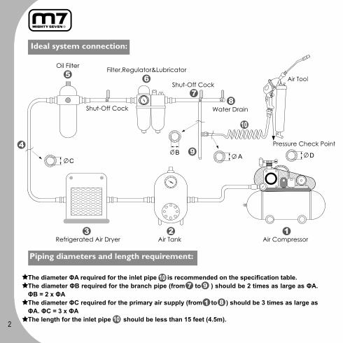
Ideal system connection:
Piping diameters and length requirement:
The diameter ΦA required for the inlet pipe is recommended on the specification table.The diameter ΦB required for the branch pipe (from to ) should be 2 times as large as ΦA. ΦB = 2 x ΦAThe diameter ΦC required for the primary air supply (from to ) should be 3 times as large as ΦA. ΦC = 3 x ΦAThe length for the inlet pipe should be less than 15 feet (4.5m).

3
1. To prevent grease leakage, make sure to wrap a few turns of thread seal tape around the connecting thread on the outlet tube before connecting it to the main housing.
2. While mounting the grease cartridge onto the grease gun, the pressure relief valve should be depressed al the way till the grease cartridge being tightened firmly.
3. To avoid the risk of damage, the recommended working pressure / air source should not exceed 10.34 Bar (150psi).
4. While replacing a new grease cartridge, make sure the rim dimension of it should be less than 54.8mm.
5. Follow all the recycling laws of waste disposal once this tool is no longer usable.
Warning:

4
Guide d’utilisation - Pompe à graisse pneumatique
1. La pression d'air maximale recommandée ne devrait jamais excéder les 90 psi (6,3bar). Une utilisation à une pression d'air supérieur peut causer des dommages à l'outil et/ou pour son utilisateur.
2. L'air à la sorti du compresseur devrait être refroidi et passer à travers un filtre capteur d'humidité pour éviter les risques de condensation à l'intérieur de l'outil. L'humidité et la condensation peuvent créer de la rouille et une usure prématurée de l'outil. Pour cette raison, il est recommandé d'installer un filtre à air/lubrificateur quelque part entre l'outil pneumatique et le compresseur.
3. Utilisez un compresseur avec une capacité adaptée pour chaque outil.
4. Nettoyez le tuyau d'alimentation avec une décharge d'air avant chaque utilisation. Ceci évitera que de l'humidité et/ou des impuretés ne pénètrent à l'intérieur de l'outil et ne crée des problèmes de fonctionnement ou une usure prématurée.
1.L’outil ne doit pas être utilisé dans un lieu ayant une atmosphère potentiellement explosive.
2.Il est fortement conseillé d'utiliser ce genre d'outils avec une prise au sol ferme et solide.
3.Toujours utiliser l'outillage pneumatique dans un endroit bien ventilé.
4.Des installations encombrées et mal organisées sont une des principales causes de blessures en milieu de travail. Une aire de travail propre et libre de tout obstacle est requise pour assurer la sécurité au travail.
Environnement de travail:
Pression et alimentation en air :

5
Le diamètre øA requis pour le tuyau d’alimentation flexible est mentionné dans le tableau fourni en annexe.Le diamètre øB requis pour le tuyau d’arrivée (de à ) doit être égal à deux fois celui de øA. øB=2 x øALe diamètre øC requis pour le tuyau de distribution (de à ) doit être égale à trois fois celui deøA øC=3 x øALa longueur du tuyau d’alimentation flexible doit être inférieure à 4.5 mètres.
Système de régulation d'air recommandé:
Connectique et tuyau d’alimentation:

6
Attention:
1. Pour prévenir toute fuite de graisse, appliquer quelques tours de ruban de téflon sur les filets de l’applicateur avant de le connecter à la pompe à graisse.
2. Lors du montage de la cartouche de graisse, la valve d’échappement doit être enfoncée à fond jusqu’à ce que la cartouche soit revissée fermement.
3. Pour éviter tout dommage à l’outil, la pression d’air maximal utilisé ne devrait pas dépasser les 10.34 Bar (150psi).
4. Avant de revisser une nouvelle cartouche, s’assurer que son diamètre extérieur soit inférieur à 54.8mm.
5. Selon les lois en vigueur, disposer des cartouches usées dans une déchèterie pour qu’elle soit recyclée.

7
1. Es ist strikt verboten, die Druckluftschlagschrauber in einem explosionsgefährdeten Arbeitsumfeld zu benutzen.
2. Es ist ratsam, das Werkzeug auf einer festen Arbeitsfläche zu verwenden, z. B. auf einem festen und ebenen Arbeitsplatz.
3. Beachten Sie, dass die Arbeitsumgebung mit dem Druckluftwerkzeug immer gut belüftet sein soll.
4. Vor der Benutzung eines Druckluftwerkzeugs sichern Sie eine saubere, geräumige und feste Arbeitsumgebung ab, da Rutschen, Anstoßen und Zubruchgehen die Hauptgründe für Schadensentstehung sind.
Sicherheitshinweise:
Luftversorgungsystem:
Bitte lesen Sie die beigelegte Anweisung sorgfältig vor der Installation, der Arbeit, Wartung und dem Wechsel des Zubehörs mit der Fettpresse.
1. Der in der Bedienungsanleitung angegebene maximale Arbeitsluftdruck, 90 psi bzw. 6,3 bar, für das Druckluftwerkzeug ist NICHT zu überschreiten, da dies zu Verletzungen und erhöhtem Materialverschleiß führen kann.
2. Die Druckluftzufuhr soll durch den in der Anlage eingebauten Lufttrockner abgekühlt werden und am Druckluftabgang durch den installierten Filter gefiltert werden. Trotzdem könnte, je nach den Umgebungsverhältnissen, immer wieder Kondenswasser in der Leitung entstehen. Die Feuchtigkeit verursacht bekanntlich Schäden und Leistungsverlust für das Werkzeug. Daher empfehlen wir unseren Kunden, eine Wartungseinheit wie den „Filter, Regler & Öler“ an einer Stelle zwischen der Luftzufuhr und dem Werkzeug zu installieren. Diese zusätzliche Wartungseinheit gewährleistet ein ideales Luftversorgungsystem für die Arbeit mit dem Werkzeug und verhindert gleichzeitig die Korrosionsbildung.
3. Bitte verwenden Sie immer einen Kompressor, der die passende Luftkapazität für das Gerät hat. 4. Vor dem Anschluss eines Druckluftwerkzeugs reinigen Sie mit Gebläseluft den Luftschlauch.
Dies verhindert, dass die in dem Luftschlauch existierende Feuchtigkeit und Staub ins Werkzeug eindringen und schützt so vor Korrosionsbildung und Verschleiß des Werkzeugs.
8
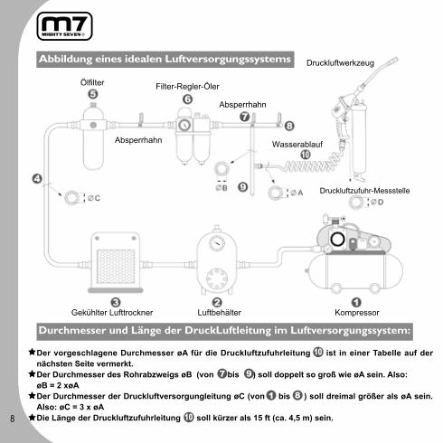
Durchmesser und Länge der DruckLuftleitung im Luftversorgungssystem:
Der vorgeschlagene Durchmesser øA für die Druckluftzufuhrleitung ist in einer Tabelle auf der nächsten Seite vermerkt. Der Durchmesser des Rohrabzweigs øB (von bis ) soll doppelt so groß wie øA sein. Also:øB = 2 xøADer Durchmesser der Druckluftversorgungleitung øC (von bis ) soll dreimal größer als øA sein. Also: øC = 3 x øADie Länge der Druckluftzufuhrleitung soll kürzer als 15 ft (ca. 4,5 m) sein.

9
1. Vor der richtigen Verwendung mit der Ausblaspistole ist ein kurzer Testanlauf vorzunehmen. Dies versichert, dass keine Leitungsleckage vorhanden ist.
2. Vor der Verwendung mit der Kartusche sollte man zuerst einen Testlauf starten, um es festzustellen, dass das Druckventil funktioniert und richtig eingestellt ist.
3. Um die Arbeitsgefahr zu vermeiden, darf die empfohlene Arbeitsdruck / Betriebsdruck NICHT über 10.34 Bar (150psi) sein.
4. Nach einem Zubehörwechsel, z.B., eine neue Kartusche, stellen Sie sicher, dass die Außenzone weniger als 54,8mm sein sollte.
5. Nach der endgültigen Abnutzung der Fettpresse befolgen Sie alle Umweltschutzrechtlinien für die Abfallentsorgung bzw. Abfallbeseitigung.
Allgemeine Sicherheitshinweise:

10
1. El uso de estas herramientas en cualquier ambiente potencialmente explosivo está totalmente prohibido.
2. Es siempre recomendado que este tipo de herramientas sean operadas parándose sobre un lugar sólido o firme.
3. Siempre usar estas herramientas en un lugar con buena ventilación.4. Resbalarse, tropezarse y caerse son las mayores causas de daños potencialmente
serios, por lo que se recomienda operar las herramientas en una superficie limpia y libre de abarrotamiento dentro del área de trabajo.
Ambiente de trabajo:
Requerimientos de surtido de aire y conexiones:
Lea este manual cuidadosamente antes de instalar, operar, realizar el servicio técnico o la reparación de la herramienta.
1. La presión máxima de operación no debe exceder de 90 psi (6.3bar). Una presión de aire mayor podría crear condiciones de operación no seguras para la herramienta y el usuario.
2. El aire comprimido debe ser enfriado y tener un filtro de agua instalado en el lado de salida del compresor. Aún con el filtro de agua instalado, algo de agua podría condensarse todavía en las tuberías o la manguera y entrar en el mecanismo de la herramienta, causando daños prematuros a la misma. Por ello es recomendable instalar un dispositivo filtro-lubricador de aire en algún punto de la línea entre la herramienta y el compresor.
3. Siempre usar el compresor de aire de la capacidad apropiada para operar cada herramienta.
4. Limpiar la manguera con un soplo de aire comprimido antes de conectar la manguera a la herramienta de aire. Esto evitará que la humedad y la suciedad dentro de la manguera ingresen a la herramienta causando su oxidación o malfuncionamiento.

11
El diámetro øA requerido para el tubo de entrada es recomendado en la tabla de datos mostrada en la siguiente página.El diámetro øB requerido para el tubo ramificado (va del punto al ) debe ser el doble del diámetro de øA. øB = 2 x øAEl diámetro øC requerido para el surtido principal de aire (del punto al ) debe ser 3 veces el tamaño de øA. øC = 3 x øA La longitud del tubo de entrada debe ser menor a 15 pies (4.5m).
Requerimientos de longitud y diámetro de las tuberías:
Filtro de aceite
Liave de cierre

12
1.Para prevenir fuga de grasa, enrolle cinta aislante alrededor de la rosca del tubo de salida antes de conectarlo al cuerpo de la herramienta.
2.Al cargar el cartucho de grasa en la pistola engrasadora, debe de presionar la válvula de liberación de presión hasta que el cartucho de grasa esté ajustado de manera firme a la herramienta neumática.
3.Para no dañar la herramienta, evite trabajar a presiones mayores de 10.5 kgf / cm² (150psi).4.Al reemplazar un nuevo cartucho de grasa, asegúrese que el diámetro de su borde sea menor a 54.8mm.
5. Siga todas las leyes de reciclaje acerca para deshacerse de la herramienta cuando ésta ya no le sea útil.
Advertencia:

13
1. Nunca trabalhe com esta ferramenta pneumática em ambientes potencialmente explosivos.
2. Deve oferecer uma base firme e sólida o piso sobre o qual o operador trabalhará com esta ferramenta pneumática.
3. Trabalhe com esta ferramenta somente em áreas bem ventiladas. 4. Tropeços, escorregões e quedas, enquanto estiver trabalhando com ferramentas
pneumáticas, podem ser potencialmente perigosos. Procure manter a área de trabalho seca e livre de obstáculos.
Recomendações sobre a área de trabalho:
Requisitos para a linha de ar e conexões:
Leia atentamente este manual antes de instalar, operar, carregar ou reparar sua engraxadeira pneumática.
1. A pressão máxima de trabalho não deve ultrapassar 90 psi (6,3 bar). Pressões mais altas podem danificar a ferramenta e machucar o operador.
2. O ar comprimido deve ser resfriado e filtrado na saída do compressor. Mesmo tomando estas medidas, um pouco de umidade pode se condensar dentro das tubulações e entrar na ferramenta pneumática, reduzindo sua vida útil. Por essa razão é recomendada a instalação de um conjunto de filtro e lubrificador de ar em algum ponto da linha entre a ferramenta e o compressor.
3. O compressor deve ter capacidade compatível com o consumo do número de ferramentas pneumáticas a ele conectadas.
4. Limpe o interior da mangueira com um jato de ar comprimido antes de conectá-la à ferramenta pneumática. Esse procedimento evita que sujeira e umidade sejam carregadas para dentro da ferramenta, danificando-a.

14
O diâmetro A requerido para a tubulação está na tabela de especificações deste manual.O diâmetro interno B da ramificação da tubulação de ar (ponto a ) deve ser duas vezes o valor do diâmetro A.O diâmetro interno C da tubulação rígida (ponto a ) deve ser três vezes o diâmetro A.O comprimento total da mangueira flexível de ar não deve ultrapassar 15 pés (4,50 m).
Especificações de diâmetro e comprimento de mangueiras e tubulações:

15
1. Para prevenir o vazamento de graxa, antes de conectar o tubo de descarga ao corpo da ferramenta, aplique algumas voltas de fita plástica de vedação em torno da rosca do tubo.
2. Ao encaixar o cartucho de graxa, pressione a válvula de alivio de pressão da engraxadeira para que o cartucho possa ser firmemente fixado à ferramenta pneumática.
3. Evite acidentes não excedendo a pressão de trabalho de 150 psi (10,34 bar).4. Ao instalar um novo cartucho de graxa, certifique-se que o diâmetro de sua borda não ultrapasse 54,8 mm.
5. Siga as recomendações de reciclagem local, evitando descartar esta engraxadeira no meio ambiente, quando
ela não for mais útil.
Aviso importante:
16
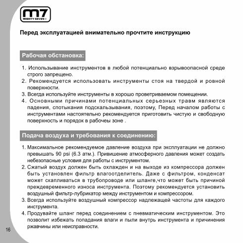
1. Использывание инструментов в любой потенциально взрывоопасной среде строго запрещено.
2. Рекомендуется использовать инструменты стоя на твердой и ровной поверхности.
3. Всегда используйте инструменты в хорошо проветриваемом помещении. 4. Основными причинами потенциальных серьезных травм являются
падения, спотыкания подскальзывания, поэтому, Перед началом работы с инструментами настоятельно рекомендуется приготовить чистую и свободную поверхность и порядок в рабочеы зоне .
Рабочая обстановка:
Подача воздуха и требования к соединению:
Перед эксплуатацией внимательно прочтите инструкцию
1. Максимальное рекомендуемое давление воздуха при эксплуатации не должно превышать 90 psi (6.3 атм.). Привишение атмосферного давления может создать небезопасные условия для работы с инструментом.
2. Сжатый воздух должен быть охлажден и на выходе из компрессора должен быть установлен фильтр влагоотделитель. Даже с фильтром, конденсат может скапливаться в трубопроводе или шланге,что может быть причиной преждевременного износа инструмента. Поэтому рекомендуется установить воздушный фильтр-лубрикатор между инструментом и компрессором.
3. Всегда используйте воздушный компрессор надлежащей частоты для каждого инструмента.
4. Продувайте шланг перед соединением с пневматическим инструментом. Это позволит избежать попадания влаги и пыли внутрь инструмента и причинения ржавчины или неисправности.

17
Диаметр ΦA подключаемого шланга в соответствии с таблицей. Диаметр ΦB промежуточного соединения (между и ) должен быть в 2 раза больше, чем ΦA. ΦB = 2 х ΦA Диаметр ΦC, необходимый для первичной подачи воздуха (от к ) должно быть в 3 раза больше, чем ΦA. ΦC = 3 х ΦA Длина шланга ~ должна быть меньше 15 футов (4.5 метра).
Требования к диаметру и длинне соединения:

18
1.Чтобы предотвратить протекание смазочного материала, необходимо нанести уплотнитель на винтовую часть трубки перед тем, как соединить ее со шприцом.
2.Отпустите спусковой клапан, пока идет загрузка картриджа.
3.Для предотвращения повреждений рекомендуемое рабочее давление не должно превышать 150psi (10,34 бар).
4.Во время замены картриджа следите за тем, чтобы внутренний диаметр кольца-уплотнителя не был более 54,8мм.
5.После прекращения срока эксплуатации шприца утилизируйте его в соответствие с местными
законами.
Внимание:

19

20

21

22
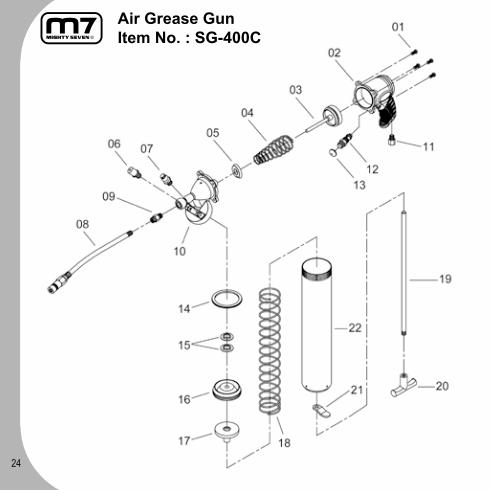
Air Grease GunItem No. : SG-400
23
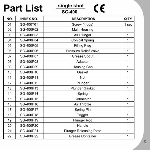
Part List SG-400single shot
NO. INDEX NO. DESCRIPTION Q'TY01020304050607080910111213141516171819202122
1 set111111111111111111111
SG-400P14SG-400P15SG-400P16SG-400P17SG-400P18SG-400P19SG-400P20SG-400P21SG-400P22
SG-400T01SG-400P02SG-400P03SG-400P04SG-400P05SG-400P06SG-400P07SG-400P08SG-400P09SG-400P10SG-400P11SG-400P12SG-400P13
SpringConnectorAir ThrottleSpring Pin
TriggerPlunger Rod
HandlePlunger Releasing Plate
Grease Container
Screw (4 pcs)Main Housing
Air PlungerConical Spring
Filling PlugPressure Relief Valve
Grease SpoutAdapter
Housing CapGasket
NutPlunger
Plunger Gasket
24
Air Grease GunItem No. : SG-400C

25
Part List SG-400Csingle shot

26
Air Grease GunItem No. : SG-401

27
Part List SG-401continuous
DESCRIPTIONNO. INDEX NO. D'TY

28
Air Grease GunItem No. : SG-500
29
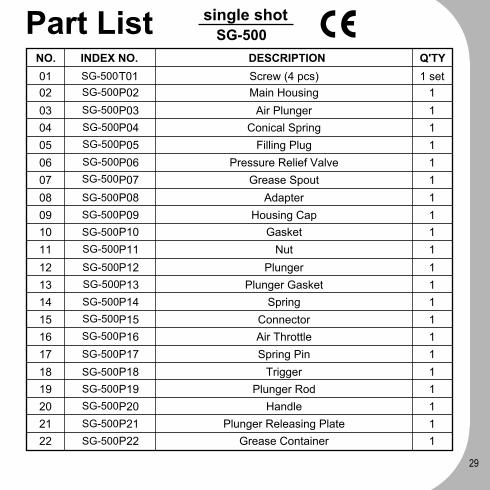
Part List SG-500single shot
NO. INDEX NO. DESCRIPTION Q'TY01020304050607080910111213141516171819202122
1 set111111111111111111111
SG-400P14SG-400P15SG-400P16SG-400P17SG-400P18SG-400P19SG-400P20SG-400P21SG-400P22
SG-400T01SG-400P02SG-400P03SG-400P04SG-400P05SG-400P06SG-400P07SG-400P08SG-400P09SG-400P10SG-400P11SG-400P12SG-400P13
SpringConnectorAir ThrottleSpring Pin
TriggerPlunger Rod
HandlePlunger Releasing Plate
Grease Container
Screw (4 pcs)Main Housing
Air PlungerConical Spring
Filling PlugPressure Relief Valve
Grease SpoutAdapter
Housing CapGasket
NutPlunger
Plunger Gasket
SG-500SG-500
SG-500SG-500SG-500
SG-500SG-500
SG-500SG-500SG-500SG-500
SG-500SG-500SG-500SG-500SG-500
SG-500
SG-500SG-500SG-500
SG-500SG-500
30
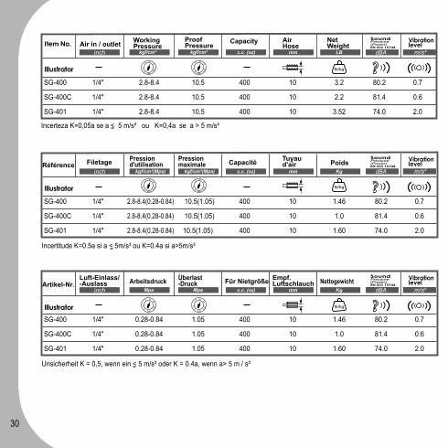
SG-400 1/4" 2.8-8.4(0.28-0.84) 10.5(1.05) 400 10 1.46 80.2 0.7
SG-400C 1/4" 2.8-8.4(0.28-0.84) 10.5(1.05) 400 10 1.0 81.4 0.6
SG-401 1/4" 2.8-8.4(0.28-0.84) 10.5(1.05) 400 10 1.60 74.0 2.0
SG-400 1/4" 0.28-0.84 1.05 400 10 1.46 80.2 0.7
SG-400C 1/4" 0.28-0.84 1.05 400 10 1.0 81.4 0.6
SG-401 1/4" 0.28-0.84 1.05 400 10 1.60 74.0 2.0
Filetage
Luft-Einlass/-Auslass
Pressiond'utilisation
Arbeitsdruck
Pressionmaximale
Überlast-Druck
Capacité
Für Nietgröße
Tuyaud'air
Empf. Luftschlauch
Poids
Nettogewicht
kgf/cm²(Mpa)
Mpa
kgf/cm²(Mpa)
Mpa
c.c. (oz)
c.c. (oz)
mm
mm
Kg
Kg
SG-400 1/4" 2.8-8.4 10.5 400 10 3.2 80.2 0.7
SG-400C 1/4" 2.8-8.4 10.5 400 10 2.2 81.4 0.6
SG-401 1/4" 2.8-8.4 10.5 400 10 3.52 74.0 2.0
Air in / outlet WorkingPressure
Proof Pressure Capacity Air
HoseNet Weight
kgf/cm² kgf/cm² c.c. (oz) mm LB
Incerteza K=0,05a se a < 5 m/s² ou K=0,4a se a > 5 m/s²
Incertitude K=0.5a si a < 5m/s² ou K=0.4a si a>5m/s²
Unsicherheit K = 0,5, wenn ein < 5 m/s² oder K = 0.4a, wenn a> 5 m / s²
Référence
Artikel-Nr.
Illustrator
Illustrator
Illustrator
2
2 68
10110
bar
2
2 68
10110
bar
lb/kg
2
2 68
10110
bar
2
2 68
10110
bar
lb/kg
2
2 68
10110
bar
2
2 68
10110
bar
lb/kg

31
SG-400 1/4" 2.8-8.4(0.28-0.84) 10.5(1.05) 400 10 1.46 80.2 0.7
SG-400C 1/4" 2.8-8.4(0.28-0.84) 10.5(1.05) 400 10 1.0 80.2 0.7
SG-401 1/4" 2.8-8.4(0.28-0.84) 10.5(1.05) 400 10 1.60 74.0 2.0
SG-400 1/4" 2.74 a 8.23 10.29 400 3/8" 1.46 80.2 0.7
SG-400C 1/4" 2.74 a 8.23 10.29 400 3/8" 1.0 80.2 0.7
SG-401 1/4" 2.74 a 8.23 10.29 400 3/8" 1.60 74.0 2.0
Entrada / Salida Aire
Conexão
Размер отверстия
Presión de Operación
Pressão de Trabalho
Рабочеедавление
Presión de Prueba
Pressão Máxima de Alimentação
Прoбноедавление
Capacidad de remache
Espessura dos rebites
Возможность
Manguerade Aire
Diâmetro interno da mangueira
Миним. Внутр. Диам. Шланга
Peso Neto
Peso
Вес
bar
kgf/cm²(Mpa)
Mpa
bar
kgf/cm²(Mpa)
Mpa
c.c. (oz)
c.c. (oz)
c.c. (oz)
mm
mm
Inch
Kg
Kg
Kg
variable K=0.5a si a < 5 m/s² ó K=0.4a si a>5 m/s²
Incerteza K=0,05a se a < 5 m/s² ou K=0,4a se a > 5 m/s²
Modelo
Código
Арт No.
SG-400 1/4" 0.28-0.84 1.05 400 10 1.46 80.2 0.7
SG-400C 1/4" 0.28-0.84 1.05 400 10 1.0 80.2 0.7
SG-401 1/4" 0.28-0.84 1.05 400 10 1.60 74.0 2.0
Погрешность K=0.5a, если a < 5 m/s² или K=0.4a если a>5 m/s²
Illustrator
Illustrator
Illustrator
2
2 68
10110
bar
2
2 68
10110
bar
lb/kg
2
2 68
10110
bar
2
2 68
10110
bar
lb/kg
2
2 68
10110
bar
2
2 68
10110
bar
lb/kg

32
EC DECLARATION OF CONFORMITY
.
Original Language
Serial Number: Please refer to the tool
Air Grease Gun
Item No.: SG-400 SG-400C SG-401
We declare under our own responsibility that the above machinery fulfils all the
relevant provisions of Machinery Directive 2006/42/EC and its amendment and
is manufactured and tested according to the following standards:
EN 792-1 / EN ISO 15744 / EN 28662-1
Declared in: Taichung, TaiwanDated:01/01/2010
Jonney ChenDeclared by: QA Manager
Manufacturer:
Mighty Seven International Co., Ltd.
No. 70-25,Ching Qunag Rd., Wu-Jih Shiang,
Taichung Hsien, 41466 Taiwan
www.mighty-seven.com
Authorized contact, to compile the technical files :
King Tony France
3 Rue des imprimeurs ZI République Nord 1.
86000 POITIERS FRANCE
TEL:(+33) 5-49-30-30-90
E-MAIL:[email protected]
Signature

33
.
traduit de la langue originale
Numéro de série : se référer au numéro inscrit sur la machine
Pompe à graisse pneumatique
Référence: SG-400 SG-400C SG-401
Nous déclarons sous notre propre responsabilité que les outils sus mentionnés sont
conforme aux provisions relative à la directive outillage 2006/42/EC et ses
amendements
et qu’ils ont été fabriqués et testés selon les standards suivants :
EN 792-1 / EN ISO 15744 / EN 28662-1
Déclaré à: Taichung, Taiwan Date: 01/01/2010
Jonney ChenDeclared by: QA Manager
Fabricant:
Mighty Seven International Co., Ltd.
No. 70-25,Ching Qunag Rd., Wu-Jih Shiang,
Taichung Hsien, 41466 Taiwan
www.mighty-seven.com
Personne autorisée pour établir les fiches techniques:
King Tony France
3 Rue des imprimeurs ZI République Nord 1. 86000 POITIERS
FRANCE
TEL:(+33) 5-49-30-30-90
E-MAIL:[email protected]
Signature

34
.
Übersetzung aus der Original-Sprache
Seriennummer: bitte bei Frage immer angeben!
Fettpresse
Artikel-Nr.SG-400 SG-400C SG-401
Wir erklären in eigener Verantwortung, dass folgendes Produkt alle einschlägigen
Bestimmungen der Maschinen-Richtlinie 2006/42/EC erfüllt und deren
Änderungen, und dass es hergestellt wird und nach den folgenden Normen geprüft
wird:
EN 792-1 / EN ISO 15744 / EN 28662-1
Erklärt in: Taichung, Taiwan Datum: 01/01/2010
Jonney ChenErklärt von: QA Manager
Der Hersteller:
Mighty Seven International Co., Ltd.
No. 70-25,Ching Qunag Rd., Wu-Jih Shiang,
Taichung Hsien, 41466 Taiwan
www.mighty-seven.com
Autorisierte Person, die zur Erstellung des technischen
Dossiers ist :
King Tony France
3 Rue des imprimeurs ZI République Nord 1.
86000 POITIERS FRANCE
TEL:(+33) 5-49-30-30-90
E-MAIL:[email protected]
Unterschrift:

35
.
Traducción del lenguaje original
Número de serie: por favor ver la herramienta
Pistola Engrasadora Neumática
Modelo :SG-400 SG-400C SG-401
Declaramos bajo nuestra propia responsabilidad que la maquinaria arriba
mencionada cumple con todas las provisiones relevantes de la Directiva de
Maquinaria 2006/42/EC y sus enmiendas y ha sido fabricado y probado de acuerdo
a los siguientes estándares:
EN 792-1 / EN ISO 15744 / EN 28662-1
Declarado en: Taichung, Taiwan Fecha: 01/01/2010
Jonney ChenDeclarado por: Gerente de Control de Calidad
Fabricante:
Mighty Seven International Co., Ltd.
No. 70-25,Ching Qunag Rd., Wu-Jih Shiang,
Taichung Hsien, 41466 Taiwan
www.mighty-seven.com
Contacto Autorizado, para recopilar los archivos técnicos :
King Tony France
3 Rue des imprimeurs ZI République Nord 1. 86000 POITIERS
FRANCE
TEL:(+33) 5-49-30-30-90
E-MAIL:[email protected]
Firma

36
.
tradução da língua original
número de série: por favor, procure-o na ferramenta
Engraxadeira pneumática
Código: SG-400 SG-400C SG-401
Declaramos sob nossa responsabilidade que o equipamento acima cumpre todos
os requisitos relevantes da Diretriz para Equipamentos 2006/42/EC e seus anexos,
tendo
sido fabricado e testado de acordo com a(s) seguinte(s) normas:
EN 792-1 / EN ISO 15744 / EN 28662-1
Declarada em: Taichung, Taiwan Datada de: 01/01/2010
Jonney ChenDeclarada pelo Gerente da Qualidade
Fabricante:
Mighty Seven International Co., Ltd.
No. 70-25,Ching Qunag Rd., Wu-Jih Shiang,
Taichung Hsien, 41466 Taiwan
www.mighty-seven.com
Contato responsável pelas informações técnicas:
King Tony France
3 Rue des imprimeurs ZI République Nord 1. 86000 POITIERS
FRANCE
TEL:(+33) 5-49-30-30-90
E-MAIL:[email protected]
Assinada por

37
.
Перевод с языка оригиналасерийный номер: смотрите на инструментеШприц плунжерный пневматический Арт No.: SG-400 SG-400C SG-401
Мы удостоверяем, что данное оборудование соответствует следующим нормам качества 2006/42/EC и все технологические изменения конструкции и производства были подвергнуты испытаниям и сертифицированы по следующим стандартам качества:EN 792-1 / EN ISO 15744 / EN 28662-1
Удостоверено в: Taichung, Taiwan Дата: 01/01/2010
Jonney ChenНачальник службы технического контроля
Производитель
Mighty Seven International Co., Ltd.
No. 70-25,Ching Qunag Rd., Wu-Jih Shiang,
Taichung Hsien, 41466 Taiwan
www.mighty-seven.com
Официальный представитель , представляющий
техническую документацию
King Tony France
3 Rue des imprimeurs ZI République Nord 1. 86000 POITIERS
FRANCE
TEL:(+33) 5-49-30-30-90
E-MAIL:[email protected]
Подпись
38
.
tłumaczenie w języku miejscowymnumer seryjny: proszę odwołać się do narzędziSmarownica pneumatyczna Pozycja nr.: SG-400 SG-400C SG-401
Oświadczamy na własną odpowiedzialność, że wyżej wymieniona maszyna jest zgodna z wszystkimi stosownymi przepisami Dyrektywy dla maszyn 2006/42/EC oraz Jej zmianami oraz jest wyprodukowana i przebadana zgodnie z następującymi normami: EN 792-1 / EN ISO 15744 / EN 28662-1
Wystawiono w:Taichung, Taiwan data:01/11/2009
Jonney ChenPoświadcza: QA Manager
Producent
Mighty Seven International Co., Ltd.
No. 70-25,Ching Qunag Rd., Wu-Jih Shiang,
Taichung Hsien, 41466 Taiwan
www.mighty-seven.com
Autoryzowany kontakt do skompletowania dokumentacji
technicznej:
King Tony France
3 Rue des imprimeurs ZI République Nord 1. 86000 POITIERS
FRANCE
TEL:(+33) 5-49-30-30-90
E-MAIL:[email protected]
podpis

39
.
la traduzione da lingua originale
seria numero :in riferimento alla attrezzatura
Pistola ingrassaggio
ItemNo : SG-400 SG-400C SG-401
sotto la propria responsabilita',che l'impianto e' stato realizzato in modo conforme
alla regola dell'arte 2006/42/EC tenuto conto degli esercizio e degli emendamento e
degli usi secondo la regola: EN 792-1 / EN ISO 15744 / EN 28662-1
dichiarante: Taichung, Taiwan data: 01/01/2010
Jonney Chendichiarante di QAManager
produttore
Mighty Seven International Co., Ltd.
No. 70-25,Ching Qunag Rd., Wu-Jih Shiang,
Taichung Hsien, 41466 Taiwan
www.mighty-seven.com
il contatto autorizzato, per complire file tecnico:
King Tony France
3 Rue des imprimeurs ZI République Nord 1. 86000 POITIERS
FRANCE
TEL:(+33) 5-49-30-30-90
E-MAIL:[email protected]
firma

40
.
μεεεεεεεε εεε μεεεεεεε εεεεεεε
εεεεμεε πεεεεεεε: πεεεεεεε εεεεεεεεε εεε εεεεεεεε
Πεεεεεε εεεεεεε εεεεε
εεεεεεεε No.: SG-400 SG-400C SG-401
Δηηηηηημη ηπηηηηηη ηηη ηη ηηηηηηη μηηηηημηηη ηηπηηηηηηηη ηηηη ηηη ηηηηηηηη
ηηηηηηηηη ηηη ηηηηηημηηηη ηημηηηη μη ηηη ηηηηηη 2006/42/EC ηηη ηηη
ηηηπηπηηηηηη ηηη, ηηηηηηηηηηηηηηη ηηη ηηηηηηηηηηη ηημηηηη μη ηη ηηηηηηηη
πηηηηπη: EN 792-1 / EN ISO 15744 / EN 28662-1
Δηλωμένο την: Taichung, Taiwan Ημερομηνία: 01/01/2010
Jonney ChenΔηλωμένο από: QA Manager
Κατασκευαστής
Mighty Seven International Co., Ltd.
No. 70-25,Ching Qunag Rd., Wu-Jih Shiang,
Taichung Hsien, 41466 Taiwan
www.mighty-seven.com
Εξουσιοδοτημένος Συνεργάτης, για οποιαδήποτε τεχνική
πληροφορία – εξυπηρέτηση:
King Tony France
3 Rue des imprimeurs ZI République Nord 1. 86000 POITIERS
FRANCE
TEL:(+33) 5-49-30-30-90
E-MAIL:[email protected]
Υπογραφή

41
.
Tulkojums no oriεinεlεs valodas
Sεrijas No.: Ludzu skatεt instrumentu
Pneimatiskε Eεεošanas pistole
Vienεba Nr.: SG-400 SG-400C SG-401
Ar šo mηs apstiprinam, ka augstηk minηtηtehnikas vienηba atbilst Eiropas Savienηbas
Tehnikas Direktηvas Nr. 2006/42/EC un tηs pielikumiem, un ir raηots, pηrbaudηts
pηc sekojošiem standartiem: EN 792-1 / EN ISO 15744 / EN 28662-1
Sertificēts: Taichung, Taiwan Datums: 01/01/2010
Jonney ChenSertificētājs : QA Manager
Ražotājs:
Mighty Seven International Co., Ltd.
No. 70-25,Ching Qunag Rd., Wu-Jih Shiang,
Taichung Hsien, 41466 Taiwan
www.mighty-seven.com
Autorizēts pārstāvis :
King Tony France
3 Rue des imprimeurs ZI République Nord 1. 86000 POITIERS
FRANCE
TEL:(+33) 5-49-30-30-90
E-MAIL:[email protected]
Paraksts

42
.
az eredeti nyelv fordítása
gyári szám : kérem keresse a szerszámon
levegεs zsírzó
Tételszám: SG-400 SG-400C SG-401
Mi, a Mighty Seven Co. Ltd. saját felelηsségre kijelentjük, hogy a fenti termék
eleget tesz az összes vonatkozó rendelkezésnek a gépekre vonatkozó 2006/42/EC
direktíváknak és módosításainak. A gyártás és tesztelés a következη szabványok
szerint történik: EN 792-1 / EN ISO 15744 / EN 28662-1
Nyilatkozat kelt: Taichung, Taiwan Dátum: 01/01/2010
Jonney ChenNyilatkozva: QA manager által
Gyártó:
Mighty Seven International Co., Ltd.
No. 70-25,Ching Qunag Rd., Wu-Jih Shiang,
Taichung Hsien, 41466 Taiwan
www.mighty-seven.com
Engedélyetett kapcsolat, hogy össeállítsa a műszaki :
King Tony France
3 Rue des imprimeurs ZI République Nord 1. 86000 POITIERS
FRANCE
TEL:(+33) 5-49-30-30-90
E-MAIL:[email protected]
aláírás

43

44

45
46

47

48

49

50

51

52

53

54

55

56

57

58

59

60

61