re 17016 2014-03 - cma/flodyne/hydradyne pdfs/brh cyl/cd70 70 bar re17016.… · osc ero g , re...
TRANSCRIPT
Bosch Rexroth AG, RE 17016, edition: 2014-03
Hydraulic cylinders Tie rod design
▶ Series 70 ▶ Component series 1X ▶ Nominal pressure 70 bar [7 MPa]
RE 17016Edition: 2014-03Replaces: 08.08Type CD70 / CG70
Features
▶ 16 types of mounting ▶ Piston Ø (ØAL) 25 ... 200 mm ▶ Piston rod Ø (ØMM) 12 ... 140 mm ▶ Stroke length up to 3 m
Project planning software Interactive Catalog System
www.boschrexroth.com/icsOnline
Contents
Features 1Ordering code: Series CD70 2, 3Ordering code: Series CG70 4, 5Position of the line connections 6Technical data 7, 8Project planning software ICS 8Diameters, forces and areas 9Overview types of mounting: Series CD70 10Overview types of mounting: Series CG70 11Dimensions CD70, CG70 12 … 75Enlarged line connection 13 and 14 76 Piston rod ends "E" and "F" 77Mounting elements 78 … 81Admissible stroke lengths 82 … 84Kinking calculation 85Support width extension 85Installation lengths and position tolerances 86Inductive proximity switch 87, 88Seals (standard versions) 89End position cushioning 89Braking force calculation 90Spare parts drawing 91Weight 92
Court
esy
of CM
A/F
lodyn
e/H
ydra
dyn
e ▪
Motion C
ontr
ol ▪
Hyd
raulic
▪ P
neu
mat
ic ▪
Ele
ctrica
l ▪
Mec
han
ical
▪ (
800)
426-5
480 ▪
ww
w.c
maf
h.c
om
2/92 CD70 / CF70 | Hydraulic cylinders, tie rod design
Bosch Rexroth AG, RE 17016, edition: 2014-03
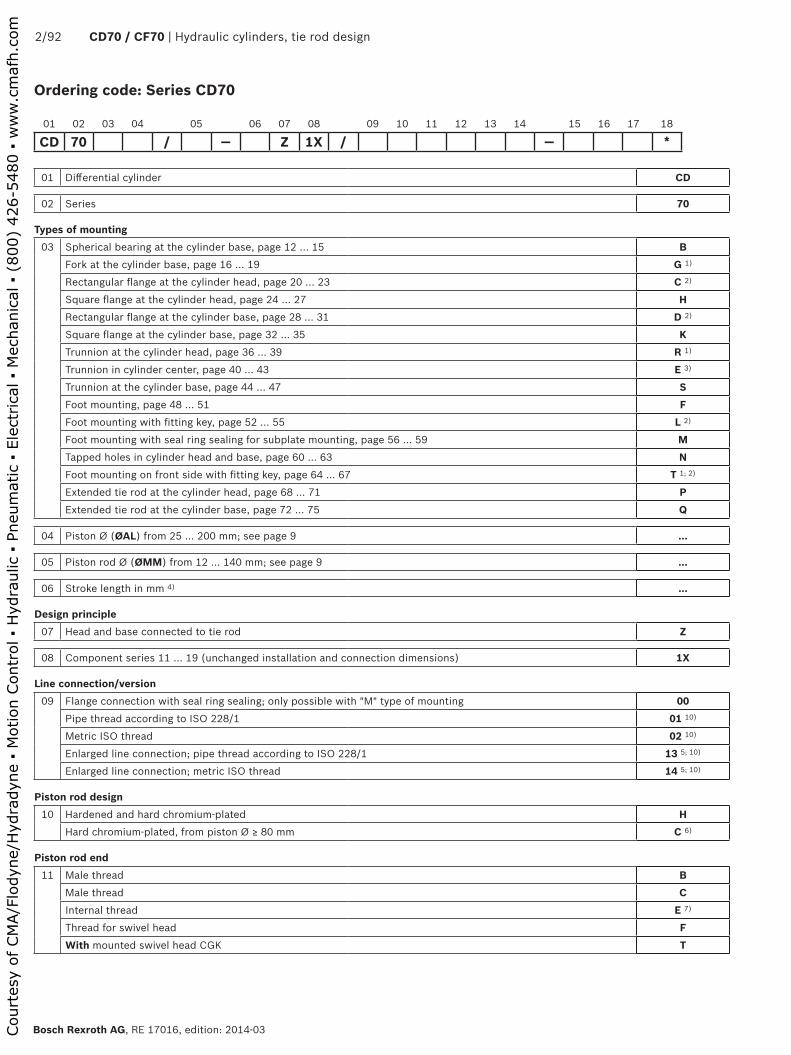
Ordering code: Series CD70
01 Differential cylinder CD
02 Series 70
Types of mounting03 Spherical bearing at the cylinder base, page 12 … 15 B
Fork at the cylinder base, page 16 … 19 G 1)
Rectangular flange at the cylinder head, page 20 ... 23 C 2)
Square flange at the cylinder head, page 24 ... 27 HRectangular flange at the cylinder base, page 28 … 31 D 2)
Square flange at the cylinder base, page 32 … 35 KTrunnion at the cylinder head, page 36 ... 39 R 1)
Trunnion in cylinder center, page 40 ... 43 E 3)
Trunnion at the cylinder base, page 44 … 47 SFoot mounting, page 48 ... 51 FFoot mounting with fitting key, page 52 ... 55 L 2)
Foot mounting with seal ring sealing for subplate mounting, page 56 ... 59 MTapped holes in cylinder head and base, page 60 ... 63 NFoot mounting on front side with fitting key, page 64 ... 67 T 1; 2)
Extended tie rod at the cylinder head, page 68 ... 71 PExtended tie rod at the cylinder base, page 72 … 75 Q
04 Piston Ø (ØAL) from 25 ... 200 mm; see page 9 ...
05 Piston rod Ø (ØMM) from 12 ... 140 mm; see page 9 ...
06 Stroke length in mm 4) ...
Design principle07 Head and base connected to tie rod Z
08 Component series 11 … 19 (unchanged installation and connection dimensions) 1X
Line connection/version09 Flange connection with seal ring sealing; only possible with "M" type of mounting 00
Pipe thread according to ISO 228/1 01 10)
Metric ISO thread 02 10)
Enlarged line connection; pipe thread according to ISO 228/1 13 5; 10)
Enlarged line connection; metric ISO thread 14 5; 10)
Piston rod design10 Hardened and hard chromium-plated H
Hard chromium-plated, from piston Ø ≥ 80 mm C 6)
Piston rod end11 Male thread B
Male thread CInternal thread E 7)
Thread for swivel head FWith mounted swivel head CGK T
01 02 03 04 05 06 07 08 09 10 11 12 13 14 15 16 17 18
CD 70 / — Z 1X / — *
Court
esy
of CM
A/F
lodyn
e/H
ydra
dyn
e ▪
Motion C
ontr
ol ▪
Hyd
raulic
▪ P
neu
mat
ic ▪
Ele
ctrica
l ▪
Mec
han
ical
▪ (
800)
426-5
480 ▪
ww
w.c
maf
h.c
om

Hydraulic cylinders, tie rod design | CD70 / CG70 3/92
RE 17016, edition: 2014-03, Bosch Rexroth AG
Ordering code: Series CD70
End position cushioning12 Without U
Base side KHead side SOn both sides D
Hydraulic fluid13 Seals, suitable for mineral oil according to DIN 51524 (HL, HLP) M
FKM seals suitable for phosphate ester (HFDR) V
Line connection/position at head14 Enter position; observe table on page 6!
View to piston rod
�
�
�
�
1 8)
2 8)
3 8)
4 8)
Line connection/position at base15 Enter position; observe table on page 6!
View to piston rod
�
�
�
�
1 8)
2 8)
3 8)
4 8)
Seals16 Standard version A
Design for low-friction operation T
17 Enter support width extension; see page 85 …
18 Further details in the plain text 9) *
1) Not possible with piston Ø 25 mm2) Not possible with piston Ø 200 mm3) Trunnion position freely selectable.
When ordering, always specify the "XV" dimension in the plain text in mm. With piston Ø 25 mm, the trunnions are at the cylinder head.
4) Observe the admissible stroke length, page 82 to 845) Dimensions see page 76. Not possible with "K" type of mounting.6) Not possible with "E" piston rod end7) Not possible with piston rod Ø 12 mm8) All graphical representations in the data sheet show position 19) Always specify the attachment of inductive proximity switches or
piston rod extension "LY" in the order in the plain text10) Not possible with "M" type of mounting
01 02 03 04 05 06 07 08 09 10 11 12 13 14 15 16 17 18
CD 70 / — Z 1X / — *
Order example: CD70B50/22-200Z1X/01HBDM1-1A
With special versions, an "X" will be inserted in the type key at the corresponding position and an SO number will be amended at the end.
Court
esy
of CM
A/F
lodyn
e/H
ydra
dyn
e ▪
Motion C
ontr
ol ▪
Hyd
raulic
▪ P
neu
mat
ic ▪
Ele
ctrica
l ▪
Mec
han
ical
▪ (
800)
426-5
480 ▪
ww
w.c
maf
h.c
om
4/92 CD70 / CF70 | Hydraulic cylinders, tie rod design
Bosch Rexroth AG, RE 17016, edition: 2014-03
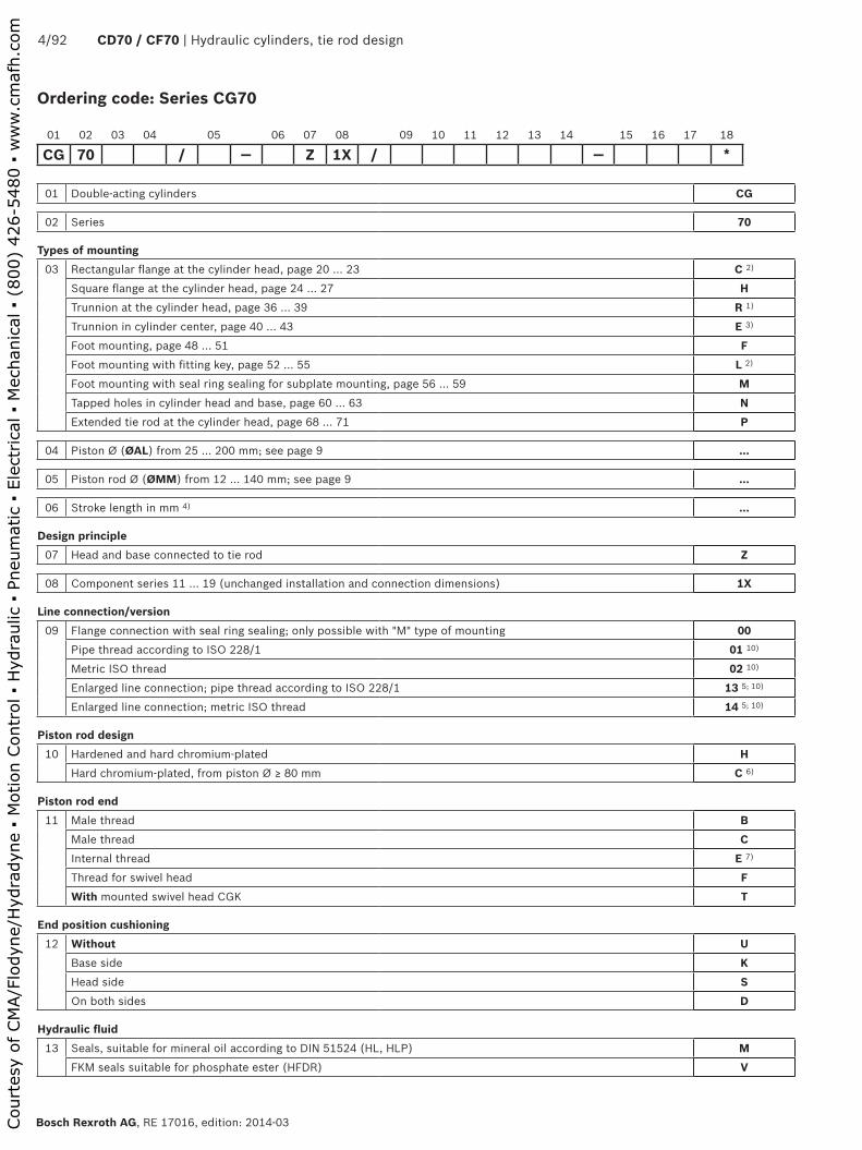
Ordering code: Series CG70
01 Double-acting cylinders CG
02 Series 70
Types of mounting03 Rectangular flange at the cylinder head, page 20 ... 23 C 2)
Square flange at the cylinder head, page 24 ... 27 HTrunnion at the cylinder head, page 36 ... 39 R 1)
Trunnion in cylinder center, page 40 ... 43 E 3)
Foot mounting, page 48 ... 51 FFoot mounting with fitting key, page 52 ... 55 L 2)
Foot mounting with seal ring sealing for subplate mounting, page 56 ... 59 MTapped holes in cylinder head and base, page 60 ... 63 NExtended tie rod at the cylinder head, page 68 ... 71 P
04 Piston Ø (ØAL) from 25 ... 200 mm; see page 9 ...
05 Piston rod Ø (ØMM) from 12 ... 140 mm; see page 9 ...
06 Stroke length in mm 4) ...
Design principle07 Head and base connected to tie rod Z
08 Component series 11 … 19 (unchanged installation and connection dimensions) 1X
Line connection/version09 Flange connection with seal ring sealing; only possible with "M" type of mounting 00
Pipe thread according to ISO 228/1 01 10)
Metric ISO thread 02 10)
Enlarged line connection; pipe thread according to ISO 228/1 13 5; 10)
Enlarged line connection; metric ISO thread 14 5; 10)
Piston rod design10 Hardened and hard chromium-plated H
Hard chromium-plated, from piston Ø ≥ 80 mm C 6)
Piston rod end11 Male thread B
Male thread CInternal thread E 7)
Thread for swivel head FWith mounted swivel head CGK T
End position cushioning12 Without U
Base side KHead side SOn both sides D
Hydraulic fluid13 Seals, suitable for mineral oil according to DIN 51524 (HL, HLP) M
FKM seals suitable for phosphate ester (HFDR) V
01 02 03 04 05 06 07 08 09 10 11 12 13 14 15 16 17 18
CG 70 / — Z 1X / — *
Court
esy
of CM
A/F
lodyn
e/H
ydra
dyn
e ▪
Motion C
ontr
ol ▪
Hyd
raulic
▪ P
neu
mat
ic ▪
Ele
ctrica
l ▪
Mec
han
ical
▪ (
800)
426-5
480 ▪
ww
w.c
maf
h.c
om

Hydraulic cylinders, tie rod design | CD70 / CG70 5/92
RE 17016, edition: 2014-03, Bosch Rexroth AG
Ordering code: Series CG70
01 02 03 04 05 06 07 08 09 10 11 12 13 14 15 16 17 18
CG 70 / — Z 1X / — *
Line connection/position at head14 Enter position; observe table on page 6!
View to piston rod
�
�
�
�
1 8)
2 8)
3 8)
4 8)
Line connection/position at base15 Enter position; observe table on page 6!
View to piston rod
�
�
�
�
1 8)
2 8)
3 8)
4 8)
Seals16 Standard version A
Design for low-friction operation T
17 Enter support width extension; see page 85 …
18 Further details in the plain text 8) *
1) Not possible with piston Ø 25 mm2) Not possible with piston Ø 200 mm3) Trunnion position freely selectable.
When ordering, always specify the "XV" dimension in the plain text in mm. With piston Ø 25 mm, the trunnions are at the cylinder head.
4) Observe the admissible stroke length, page 82 to 845) Dimensions see page 766) Not possible with "E" piston rod end7) Not possible with piston rod Ø 12 mm8) All graphical representations in the data sheet show position 19) Always specify the attachment of inductive proximity switches or
piston rod extension "LY" in the order in the plain text10) Not possible with "M" type of mounting
Order example:CG70C50/22-200Z1X/01HBDM1-1A
With special versions, an "X" will be inserted in the type key at the corresponding position and an SO number will be amended at the end.
Court
esy
of CM
A/F
lodyn
e/H
ydra
dyn
e ▪
Motion C
ontr
ol ▪
Hyd
raulic
▪ P
neu
mat
ic ▪
Ele
ctrica
l ▪
Mec
han
ical
▪ (
800)
426-5
480 ▪
ww
w.c
maf
h.c
om
� �
�
�
6/92 CD70 / CF70 | Hydraulic cylinders, tie rod design
Bosch Rexroth AG, RE 17016, edition: 2014-03
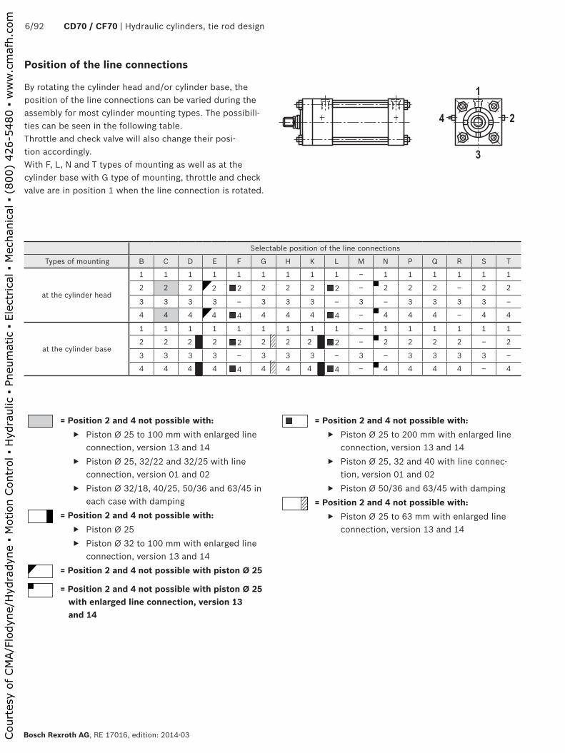
Position of the line connections
By rotating the cylinder head and/or cylinder base, the position of the line connections can be varied during the assembly for most cylinder mounting types. The possibili-ties can be seen in the following table.Throttle and check valve will also change their posi-tion accordingly.With F, L, N and T types of mounting as well as at the cylinder base with G type of mounting, throttle and check valve are in position 1 when the line connection is rotated.
= Position 2 and 4 not possible with: ▶ Piston Ø 25 to 100 mm with enlarged line
connection, version 13 and 14 ▶ Piston Ø 25, 32/22 and 32/25 with line
connection, version 01 and 02 ▶ Piston Ø 32/18, 40/25, 50/36 and 63/45 in
each case with damping= Position 2 and 4 not possible with:
▶ Piston Ø 25 ▶ Piston Ø 32 to 100 mm with enlarged line
connection, version 13 and 14= Position 2 and 4 not possible with piston Ø 25
= Position 2 and 4 not possible with piston Ø 25 with enlarged line connection, version 13 and 14
= Position 2 and 4 not possible with: ▶ Piston Ø 25 to 200 mm with enlarged line
connection, version 13 and 14 ▶ Piston Ø 25, 32 and 40 with line connec-
tion, version 01 and 02 ▶ Piston Ø 50/36 and 63/45 with damping
= Position 2 and 4 not possible with: ▶ Piston Ø 25 to 63 mm with enlarged line
connection, version 13 and 14
Selectable position of the line connections
Types of mounting B C D E F G H K L M N P Q R S T
at the cylinder head
1 1 1 1 1 1 1 1 1 – 1 1 1 1 1 1
2 2 2 2 2 2 2 2 2 – 2 2 2 – 2 2
3 3 3 3 – 3 3 3 – 3 – 3 3 3 3 –
4 4 4 4 4 4 4 4 4 – 4 4 4 – 4 4
at the cylinder base
1 1 1 1 1 1 1 1 1 – 1 1 1 1 1 1
2 2 2 2 2 2 2 2 2 – 2 2 2 2 – 2
3 3 3 3 – 3 3 3 – 3 – 3 3 3 3 –
4 4 4 4 4 4 4 4 4 – 4 4 4 4 – 4
Court
esy
of CM
A/F
lodyn
e/H
ydra
dyn
e ▪
Motion C
ontr
ol ▪
Hyd
raulic
▪ P
neu
mat
ic ▪
Ele
ctrica
l ▪
Mec
han
ical
▪ (
800)
426-5
480 ▪
ww
w.c
maf
h.c
om

Hydraulic cylinders, tie rod design | CD70 / CG70 7/92
RE 17016, edition: 2014-03, Bosch Rexroth AG
Technical data (For applications outside these parameters, please consult us!)
1) By default, hydraulic cylinders are primed with a coating (color gentian blue RAL 5010) of min. 40 μm. Other colors upon request. With hydraulic cylinders and attachment parts, the following areas are not primed or coated:
▶ All fit diameters to the customer side ▶ Sealing surfaces for line connection ▶ Sealing surfaces for flange connection ▶ Inductive proximity switches
The areas that are not painted are protected by means of a solvent-free corrosion protection agent.
2) If there are extreme loads, such as high sequence cycles, the mounting elements and threaded piston rod connections must be checked for the application.
hydraulic
Nominal pressure bar [MPa] 70 [7]
Maximum operating pressure 2)
(depending on piston Ø and type of mounting)bar [MPa] 105 [10.5]
Minimum operating pressure 3) (without load) bar [MPa] 10 [1]
Static test pressure (depending on piston Ø and type of mounting)
bar [MPa] Admissible operating pressure x 1.3
Hydraulic fluid See table below
Hydraulic fluid temperature range °C ‒20 ... +80
Viscosity range mm2/s 12 ... 380 (preferably 20 ... 100)
Maximum admissible degree of contamination of the hy-draulic fluid - cleanliness class according to ISO 4406 (c)
Class 20/18/15 4)
Stroke speed (depending on line connection) m/s 0.5
Bleeding By default
Tolerances see page 86
generalWeight kg See page 92
Installation position Any
Ambient temperature range °C ‒20 ... +80
Primer coat 1) μm Min. 40
Hydraulic fluid Classification Suitable sealing materials StandardsMineral oils HL, HLP NBR, FKM DIN 51524
Phosphate ester HFDR FKM ISO 12922
3) A minimum operating pressure is required in order to guarantee good functioning of the hydraulic cylinder. Without load, a minimum pressure of 10 bar is recommended for differential cylinders; for lower pressures as well as double-acting cylinders, please contact us.
4) The cleanliness classes specified for the components must be adhered to in hydraulic systems. Effective filtration prevents faults and at the same time increases the life cycle of the components.
For the selection of the filters see www.boschrexroth.com/filter.
Court
esy
of CM
A/F
lodyn
e/H
ydra
dyn
e ▪
Motion C
ontr
ol ▪
Hyd
raulic
▪ P
neu
mat
ic ▪
Ele
ctrica
l ▪
Mec
han
ical
▪ (
800)
426-5
480 ▪
ww
w.c
maf
h.c
om

� ���� ��� ��� ��� � ���
����
���
���
���������
8/92 CD70 / CF70 | Hydraulic cylinders, tie rod design
Bosch Rexroth AG, RE 17016, edition: 2014-03
Technical data (For applications outside these parameters, please consult us!)
Life cycle: Rexroth hydraulic cylinders correspond to the reliability recommendations for industrial applications. ≥ 10000000 double strokes in idle continuous operation or 3000 km piston travel at 70 % of the nominal pressure, without load on the piston rod, with a maximum velocity of 0.5 m/s, with a failure rate of less than 5 %.
Stroke in m →
Doub
le s
trok
es x
106
→
Notice!Boundary and application conditions:
▶ The mechanical alignment of the movement axis and thus the mounting points of hydraulic cylinder and piston rod must be ensured. Lateral forces on the guides of piston rod and piston are to be avoided. It may be necessary to consider the own weight of the hydraulic cylinder (types of mounting: B, G, R, E or S) or the piston rod.
▶ The admissible stroke length/kinking load of the piston rod and/or the hydraulic cylinder must be observed (see page 82 to 85).
▶ The maximum admissible operating pressure must be complied with in any operating state of the hydraulic cylinder. Possible pressure intensification resulting from the ratio of annulus area to piston area and possible throttling points are to be observed.
▶ Detrimental environmental influences, like e.g. aggres-sive finest particles, vapors, high temperatures, etc. as well as contaminations and deterioration of the hydraulic fluid are to be avoided.
Standards: Rexroth standard; the line connection threads are option-ally designed as pipe thread according to ISO 228/1 or as metric ISO thread.
Acceptance: Every hydraulic cylinder is tested according to Rexroth standard and complying with ISO 10100: 2001.Safety instructions: For assembly, commissioning and maintenance of hydraulic cylinders, observe the operating instruc-tions 07100-B! Service and repair works have to be performed by Bosch Rexroth AG or by personnel espe-cially trained for this purpose. In case of damage as a consequence of assembly, maintenance or repair work not performed by Bosch Rexroth AG, the warranty claim will be forfeited.Check lists for hydraulic cylinders: Hydraulic cylinders the characteristics and/or application parameters of which deviate from the values specified in the data sheet can only be offered as special version upon request. For offers, the deviations of the character-istics and/or application parameters must be described in the check lists for hydraulic cylinders (07200).
This list does not claim to be complete. In case of questions regarding the compatibility with media or exceedance of the boundary or application conditions, please contact us.
The ICS (Interactive Catalog System) is a selection and project planning aid for hydraulic cylinders. The ICS allows designers for machines and systems to quickly and reliably find the perfect hydraulic cylinder solution through logic-guided type code enquiries. This software helps to solve design and project planning tasks more quickly and
efficiently. After having been guided through the product selection, the user quickly and reliably gets the exact technical data of the selected component as well as 2D and 3D CAD data in the correct file format for all common CAD systems.
Project planning software ICS (Interactive Catalog System)
Court
esy
of CM
A/F
lodyn
e/H
ydra
dyn
e ▪
Motion C
ontr
ol ▪
Hyd
raulic
▪ P
neu
mat
ic ▪
Ele
ctrica
l ▪
Mec
han
ical
▪ (
800)
426-5
480 ▪
ww
w.c
maf
h.c
om

Hydraulic cylinders, tie rod design | CD70 / CG70 9/92
RE 17016, edition: 2014-03, Bosch Rexroth AG
Diameters, forces and areas
Operating pressure in bar
Piston Ø mm 25 32 40 50
Piston rod Ø mm 12 16 18 22 25 16 18 25 22 25 36
40Force on piston side kN 1.96 3.22 5.03 7.85
Force on rod side kN 1.55 1.19 2.19 1.69 1.25 4.21 3.99 3.06 6.32 5.87 3.78
50Force on piston side kN 2.46 4.02 6.29 9.82
Force on rod side kN 1.94 1.49 2.74 2.11 1.56 5.27 5.00 3.83 7.91 7.35 4.73
70Force on piston side kN 3.44 5.63 8.80 13.75
Force on rod side kN 2.71 2.08 3.84 2.96 2.19 7.38 7.01 5.40 11.08 10.31 6.62
105Force on piston side kN 5.16 8.45 13.20 20.62
Force on rod side kN 3.96 3.04 5.77 4.44 3.28 11.07 10.52 8.03 16.62 15.44 9.93
Piston area cm2 4.91 8.04 12.56 19.63
Annulus area cm2 3.78 2.90 5.50 4.24 3.13 10.55 10.02 7.65 15.83 14.71 9.46
Area ratio φ 1.25:1 1.6:1 1.4:1 2:1 2.5:1 1.2:1 1.25:1 1.6:1 1.25:1 1.35:1 2:1
Damping areaForce on piston side cm2 2.63 5.77 10.30 15.11
Force on rod side cm2 2.63 2.63 4.90 3.52 2.50 8.70 8.76 7.05 14.33 13.47 8.29
Max. available stroke length mm 600 800 1000 1200
Operating pressure in bar
Piston Ø mm 63 80 100
Piston rod Ø mm 25 28 36 45 36 45 56 45 50 70
40Force on piston side kN 12.47 20.10 31.42
Force on rod side kN 10.49 9.99 8.38 6.00 16.02 13.73 10.25 25.04 23.55 16.01
50Force on piston side kN 15.59 25.10 39.27
Force on rod side kN 13.12 12.50 10.49 7.62 20.03 17.16 12.80 31.29 29.43 20.02
70Force on piston side kN 21.82 35.18 54.98
Force on rod side kN 18.36 17.50 14.68 10.68 28.04 24.03 17.93 43.80 41.20 28.01
105Force on piston side kN – – –
Force on rod side kN – – – – – – – – – –
Piston area cm2 31.16 50.24 78.50
Annulus area cm2 26.25 25.01 20.98 15.26 40.07 34.34 25.62 62.60 58.88 40.04
Area ratio φ 1.2:1 1.25:1 1.4:1 2:1 1.25:1 1.4:1 2:1 1.25:1 1.35:1 2:1
Damping areaForce on piston side cm2 26.65 40.64 58.90
Force on rod side cm2 23.13 23.13 19.80 13.08 37.70 30.60 20.07 58.90 54.70 31.97
Max. available stroke length mm 1400 1700 2000
Operating pressure in bar
Piston Ø mm 125 150 200
Piston rod Ø mm 50 56 63 90 63 70 80 100 90 100 140
40Force on piston side kN 49.09 70.68 125.66
Force on rod side kN 41.20 39.20 36.59 23.63 58.17 55.25 50.54 39.23 100.13 94.16 64.03
50Force on piston side kN 61.35 88.35 –
Force on rod side kN 51.49 49.01 45.83 29.53 72.71 69.06 63.16 49.05 – – –
70Force on piston side kN 85.90 – –
Force on rod side kN 72.10 68.60 64.03 41.35 – – – – – – –
105Force on piston side kN – – –
Force on rod side kN – – – – – – – – – – –
Piston area cm2 122.66 176.63 314.00
Annulus area cm2 103.03 98.04 91.50 59.08 145.47 138.17 126.38 98.13 250.42 235.50 160.14
Area ratio φ 1.2:1 1.25:1 1.35:1 2:1 1.2:1 1.25:1 1.4:1 1.8:1 1.25:1 1.35:1 2:1
Damping areaForce on piston side cm2 103.08 138.23 275.68
Force on rod side cm2 92.50 92.50 47.20 47.20 130.10 130.10 81.70 81.70 238.70 219.00 137.50
Max. available stroke length mm 2300 2600 3000
Court
esy
of CM
A/F
lodyn
e/H
ydra
dyn
e ▪
Motion C
ontr
ol ▪
Hyd
raulic
▪ P
neu
mat
ic ▪
Ele
ctrica
l ▪
Mec
han
ical
▪ (
800)
426-5
480 ▪
ww
w.c
maf
h.c
om

10/92 CD70 / CF70 | Hydraulic cylinders, tie rod design
Bosch Rexroth AG, RE 17016, edition: 2014-03
CD70 B Page 12 ... 15
CD70 G Page 16 ... 19
CD70 C Page 20 ... 23
CD70 H Page 24 ... 27
CD70 D Page 28 ... 31
CD70 K Page 32 ... 35
CD70 R Page 36 ... 39
CD70 E Page 40 ... 43
Overview types of mounting: Series CD70
CD70 SPage 44 ... 47
CD70 FPage 48 ... 51
CD70 LPage 52 ... 55
CD70 MPage 56 ... 59
CD70 NPage 60 ... 63
CD70 TPage 64 ... 67
CD70 PPage 68 ... 71
CD70 QPage 72 ... 75
Court
esy
of CM
A/F
lodyn
e/H
ydra
dyn
e ▪
Motion C
ontr
ol ▪
Hyd
raulic
▪ P
neu
mat
ic ▪
Ele
ctrica
l ▪
Mec
han
ical
▪ (
800)
426-5
480 ▪
ww
w.c
maf
h.c
om

Hydraulic cylinders, tie rod design | CD70 / CG70 11/92
RE 17016, edition: 2014-03, Bosch Rexroth AG
CG70 C Page 20 ... 23
CG70 HPage 24 ... 27
CG70 RPage 36 ... 39
CG70 E Page 40 ... 43
Overview types of mounting: Series CG70
CG70 LPage 52 ... 55
CG70 MPage 56 ... 59
CG70 NPage 60 ... 63
CG70 PPage 68 ... 71
CG70 FPage 48 ... 51
Court
esy
of CM
A/F
lodyn
e/H
ydra
dyn
e ▪
Motion C
ontr
ol ▪
Hyd
raulic
▪ P
neu
mat
ic ▪
Ele
ctrica
l ▪
Mec
han
ical
▪ (
800)
426-5
480 ▪
ww
w.c
maf
h.c
om
���
�����
��
��
��
�� �
���
���
�� �� ��
���� �
��
��
aa
����
���
��
��
�� ��
���
��
��
���
�����
����
���
��
�����
������
12/92 CD70 / CF70 | Hydraulic cylinders, tie rod design
Bosch Rexroth AG, RE 17016, edition: 2014-03
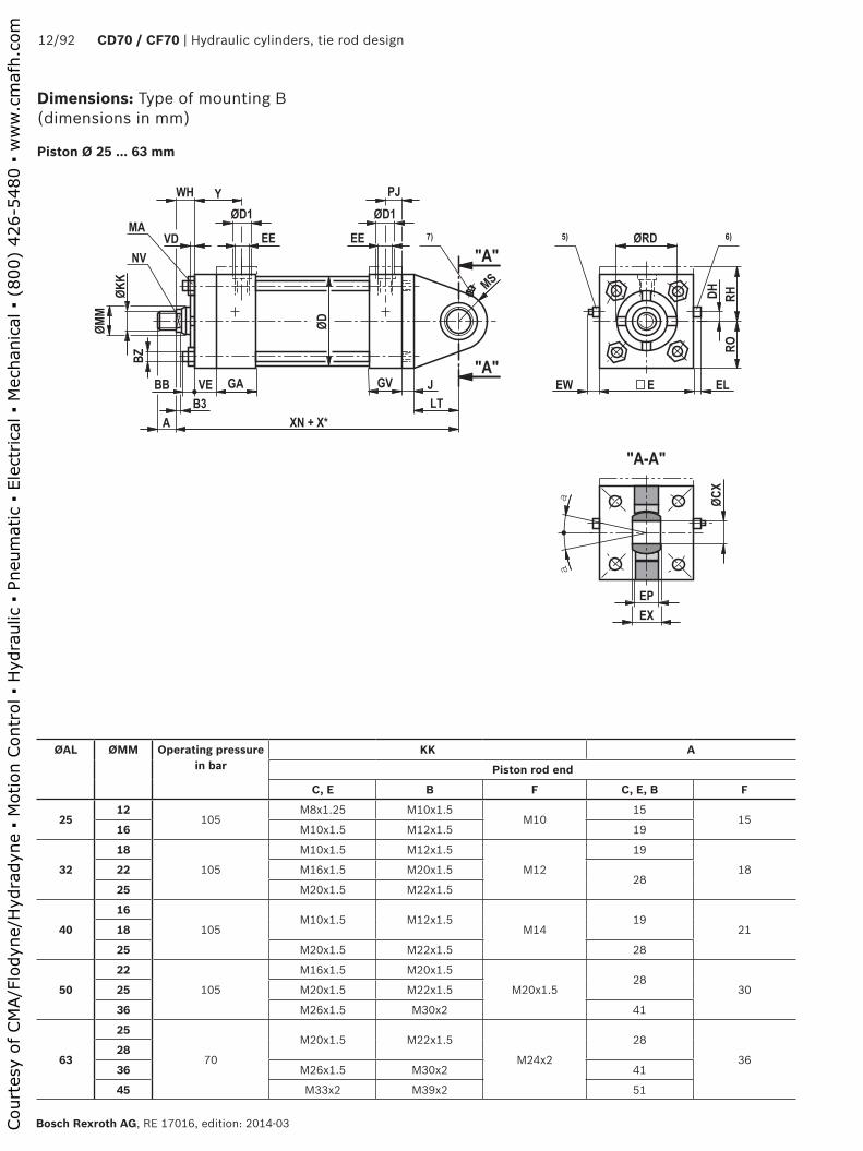
Dimensions: Type of mounting B (dimensions in mm)
Piston Ø 25 ... 63 mm
ØAL ØMM Operating pressure in bar
KK A
Piston rod end
C, E B F C, E, B F
2512
105 M8x1.25 M10x1.5
M1015
1516 M10x1.5 M12x1.5 19
32
18
105
M10x1.5 M12x1.5
M12
19
1822 M16x1.5 M20x1.528
25 M20x1.5 M22x1.5
40
16
105 M10x1.5 M12x1.5
M1419
2118
25 M20x1.5 M22x1.5 28
50
22
105
M16x1.5 M20x1.5
M20x1.528
3025 M20x1.5 M22x1.5
36 M26x1.5 M30x2 41
63
25
70
M20x1.5 M22x1.5
M24x2
28
3628
36 M26x1.5 M30x2 41
45 M33x2 M39x2 51
Court
esy
of CM
A/F
lodyn
e/H
ydra
dyn
e ▪
Motion C
ontr
ol ▪
Hyd
raulic
▪ P
neu
mat
ic ▪
Ele
ctrica
l ▪
Mec
han
ical
▪ (
800)
426-5
480 ▪
ww
w.c
maf
h.c
om
Hydraulic cylinders, tie rod design | CD70 / CG70 13/92
RE 17016, edition: 2014-03, Bosch Rexroth AG
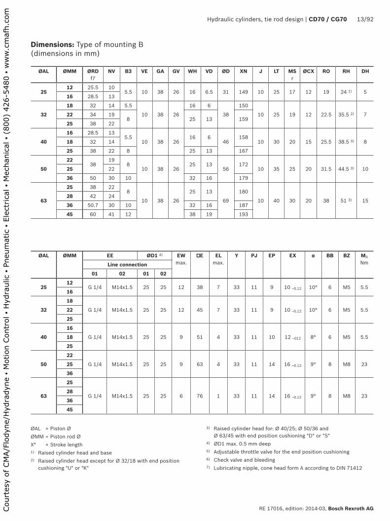
Dimensions: Type of mounting B (dimensions in mm)
ØAL ØMM ØRD f7
NV B3 VE GA GV WH VD ØD XN J LT MSr
ØCX RO RH DH
2512 25.5 10
5.5 10 38 26 16 6.5 31 149 10 25 17 12 19 24 1) 516 28.5 13
32
18 32 14 5.5
10 38 26
16 6
38
150
10 25 19 12 22.5 35.5 2) 722 34 198 25 13 159
25 38 22
40
16 28.5 135.5
10 38 2616 6
46158
10 30 20 15 25.5 38.5 3) 818 32 14
25 38 22 8 25 13 167
50
2238
198
10 38 2625 13
56172
10 35 25 20 31.5 44.5 3) 1025 22
36 50 30 10 32 16 179
63
25 38 228
10 38 26
25 13
69
180
10 40 30 20 38 51 3) 1528 42 24
36 50.7 30 10 32 16 187
45 60 41 12 38 19 193
ØAL ØMM EE ØD1 4) EWmax.
E ELmax.
Y PJ EP EX α BB BZ MA
NmLine connection
01 02 01 02
2512
G 1/4 M14x1.5 25 25 12 38 7 33 11 9 10 ‒0.12 10° 6 M5 5.516
32
18
G 1/4 M14x1.5 25 25 12 45 7 33 11 9 10 ‒0.12 10° 6 M5 5.522
25
40
16
G 1/4 M14x1.5 25 25 9 51 4 33 11 10 12 ‒012 8° 6 M5 5.518
25
50
22
G 1/4 M14x1.5 25 25 9 63 4 33 11 14 16 ‒0.12 9° 8 M8 2325
36
63
25
G 1/4 M14x1.5 25 25 6 76 1 33 11 14 16 ‒0.12 9° 8 M8 2328
36
45
ØAL = Piston ØØMM = Piston rod ØX* = Stroke length1) Raised cylinder head and base 2) Raised cylinder head except for Ø 32/18 with end position
cushioning "U" or "K"
3) Raised cylinder head for: Ø 40/25; Ø 50/36 and Ø 63/45 with end position cushioning "D" or "S"
4) ØD1 max. 0.5 mm deep5) Adjustable throttle valve for the end position cushioning6) Check valve and bleeding7) Lubricating nipple, cone head form A according to DIN 71412
Court
esy
of CM
A/F
lodyn
e/H
ydra
dyn
e ▪
Motion C
ontr
ol ▪
Hyd
raulic
▪ P
neu
mat
ic ▪
Ele
ctrica
l ▪
Mec
han
ical
▪ (
800)
426-5
480 ▪
ww
w.c
maf
h.c
om

���
�����
��
��
��
�� �
���
���
�� �� ��
���� �
��
��
aa
����
���
��
��
�� ��
���
��
��
���
�����
�����
��
�����
������
14/92 CD70 / CF70 | Hydraulic cylinders, tie rod design
Bosch Rexroth AG, RE 17016, edition: 2014-03
Dimensions: Type of mounting B (dimensions in mm)
Piston Ø 80 ... 200 mm
ØAL ØMM Operating pressure in bar
KK A
Piston rod end
C, E B F C, E, B F
80
36
70
M26x1.5 M30x2
M30x2
41
4545 M33x2 M39x2 51
56 M39x2 M45x2 57
100
45
70
M33x2 M39x2
M39x3
51
6550 M39x2 M45x2 57
70 M48x2 M56x2 76
125
50
70
M39x2 M45x2
M42x3
57
6556
63 M48x2 M56x2 76
90 M64x2 M76x2 89
150
63
50
M48x2 M56x2
M45x3
76
6870
80 M58x2 M68x2 89
100 M76x2 M95x2 101
200
90
40
M64x2 M76x2
M52x3
89
70100 M76x2 M95x2 101
140 M100x2 M130x2 140
Court
esy
of CM
A/F
lodyn
e/H
ydra
dyn
e ▪
Motion C
ontr
ol ▪
Hyd
raulic
▪ P
neu
mat
ic ▪
Ele
ctrica
l ▪
Mec
han
ical
▪ (
800)
426-5
480 ▪
ww
w.c
maf
h.c
om

Hydraulic cylinders, tie rod design | CD70 / CG70 15/92
RE 17016, edition: 2014-03, Bosch Rexroth AG
Dimensions: Type of mounting B (dimensions in mm)
ØAL ØMM ØRD f7
NV B3 VE GA GV WH VD ØD XN J LT MSr
ØCX RO DH
80
36 50 30 10
16 45 33
25 10
86
209
15 45 35 25 47.5 1545 60 41 12 3213
216
56 70 46 15 35 219
100
45 60 41 12
16 45 33
3213
106
226
15 55 42 25 57 2050 66.6 4615
35 229
70 90 60 41 16 235
125
50 66.646
15 16 45 33
35 13
135
245
15 65 55 30 70 3056 70
63 79.3 5541 16 251
90 108 75
150
63 79.3 55
15 19 51 40 38 13 160 284 20 80 70 35 82.5 3570 90 60
80 95.2 75
100 120 85
200
90 108 75
15 19 51 40 38 13 215 307 25 95 80 45 108 55100 120 85
140 158 120
ØAL ØMM EE ØD1 4) EWmax.
E ELmax.
Y PJ EP EX α BB BZ MA
NmLine connection
01 02 01 02
80
36
G 1/2 M22x1.5 34 34 12 95 11 42 14.5 18 20 -0.18 7° 10 M10 4645
56
100
45
G 1/2 M22x1.5 34 34 9 114 8 42 14.5 18 20 -0.18 7° 12 M12 8050
70
125
50
G 1/2 M22x1.5 34 34 9 140 8 42 14.5 20 22 -0.18 6° 13 M14 12556
63
90
150
63
G 3/4 M26x1.5 42 42 16 165 12 48 18 23 25 -0.12 6° 15 M16 2370
80
100
200
90
G 3/4 M26x1.5 42 42 14 216 10 48 18 30 32 -0.12 6° 15 M16 195100
140
ØAL = Piston ØØMM = Piston rod ØX* = Stroke length
4) ØD1 max. 0.5 mm deep5) Adjustable throttle valve for the end position cushioning6) Check valve and bleeding7) Lubricating nipple, cone head form A according to DIN 71412
Court
esy
of CM
A/F
lodyn
e/H
ydra
dyn
e ▪
Motion C
ontr
ol ▪
Hyd
raulic
▪ P
neu
mat
ic ▪
Ele
ctrica
l ▪
Mec
han
ical
▪ (
800)
426-5
480 ▪
ww
w.c
maf
h.c
om
��
��
���
�����
��
��
��
�� �
���
���
��
�� ��
� �
��
��
����
���
��
��
��
���
��
���
�
��
���
����
��
�
���
��
����
��
16/92 CD70 / CF70 | Hydraulic cylinders, tie rod design
Bosch Rexroth AG, RE 17016, edition: 2014-03
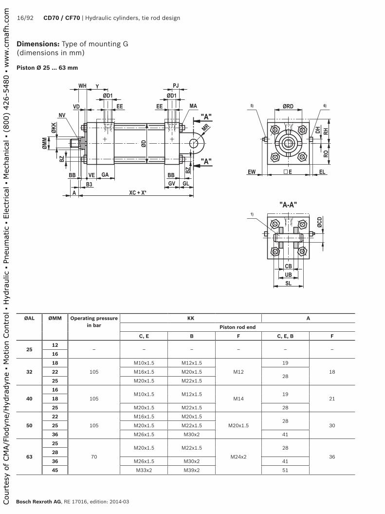
Dimensions: Type of mounting G (dimensions in mm)
Piston Ø 25 ... 63 mm
ØAL ØMM Operating pressure in bar
KK A
Piston rod end
C, E B F C, E, B F
2512
‒ ‒ ‒ ‒ ‒ ‒16
32
18
105
M10x1.5 M12x1.5
M12
19
1822 M16x1.5 M20x1.528
25 M20x1.5 M22x1.5
40
16
105M10x1.5 M12x1.5
M1419
2118
25 M20x1.5 M22x1.5 28
50
22
105
M16x1.5 M20x1.5
M20x1.528
3025 M20x1.5 M22x1.5
36 M26x1.5 M30x2 41
63
25
70
M20x1.5 M22x1.5
M24x2
28
3628
36 M26x1.5 M30x2 41
45 M33x2 M39x2 51
Court
esy
of CM
A/F
lodyn
e/H
ydra
dyn
e ▪
Motion C
ontr
ol ▪
Hyd
raulic
▪ P
neu
mat
ic ▪
Ele
ctrica
l ▪
Mec
han
ical
▪ (
800)
426-5
480 ▪
ww
w.c
maf
h.c
om

Hydraulic cylinders, tie rod design | CD70 / CG70 17/92
RE 17016, edition: 2014-03, Bosch Rexroth AG
Dimensions: Type of mounting G (dimensions in mm)
ØAL = Piston ØØMM = Piston rod ØX* = Stroke length1) Bolts and pins are included in the scope of delivery 2) Raised cylinder head except for Ø 32/18 with end position
cushioning "U" or "K"
3) Raised cylinder head for: Ø 40/25; Ø 50/36 and Ø 63/45 with end position cushioning "D" or "S"
4) ØD1 max. 0.5 mm deep5) Adjustable throttle valve for the end position cushioning6) Check valve and bleeding
ØAL ØMM ØRD NV B3 VE GA GV WH VD ØD GL XC MR r
ØCD H7 f7
RO RH DH
2512
‒ ‒ ‒ ‒ ‒ ‒ ‒ ‒ ‒ ‒ ‒ ‒ ‒ ‒ ‒ ‒16
32
18 32 14 5.5
10 38 26
16 6
38 19
134
11 12.7 22.5 35.5 2) 722 34 198 25 13 143
25 38 22
40
16 28.5 135.5
10 38 2616 6
46 19137
12 12.7 25.5 38.5 3) 818 32 14
25 38 22 8 25 13 146
50
2238
198
10 38 2625 13
56 19146
16 12.7 31.5 44.5 3) 1025 22
36 50 30 10 32 16 153
63
25 38 228
10 38 26
25 13
69 19
149
16 12.7 3851 3)
+1.415
28 42 24
36 50.7 30 10 32 16 156
45 60 41 12 38 19 162
ØAL ØMM EE ØD1 4) EW max.
E EL max.
Y PJ CB +0.5
UB SL BB BZ MA
NmLine connection
01 02 01 02
2512
‒ ‒ ‒ ‒ ‒ ‒ ‒ ‒ ‒ ‒ ‒ ‒ ‒ ‒ ‒16
32
18
G 1/4 M14x1.5 25 25 12 45 7 33 11 20 40 52 6 M5 5.522
25
40
16
G 1/4 M14x1.5 25 25 9 51 4 33 11 20 44 56 6 M5 5.518
25
50
22
G 1/4 M14x1.5 25 25 9 63 4 33 11 20 44 56 8 M8 2325
36
63
25
G 1/4 M14x1.5 25 25 6 76 1 33 11 20 44 56 8 M8 2328
36
45
Court
esy
of CM
A/F
lodyn
e/H
ydra
dyn
e ▪
Motion C
ontr
ol ▪
Hyd
raulic
▪ P
neu
mat
ic ▪
Ele
ctrica
l ▪
Mec
han
ical
▪ (
800)
426-5
480 ▪
ww
w.c
maf
h.c
om
��
��
���
�����
��
��
��
�� �
���
���
��
�� ��
� �
��
��
����
���
��
��
��
���
��
���
�
��
���
����
�
���
��
����
��
18/92 CD70 / CF70 | Hydraulic cylinders, tie rod design
Bosch Rexroth AG, RE 17016, edition: 2014-03
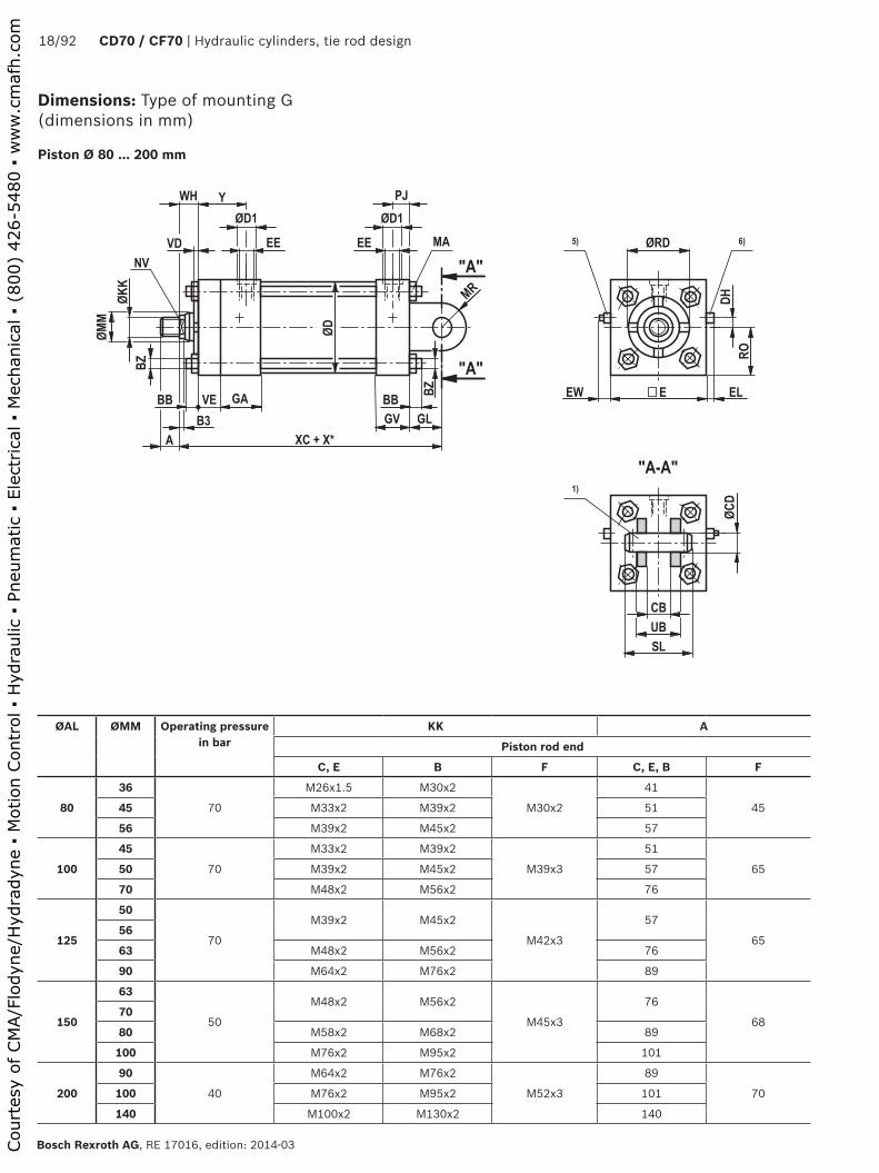
Dimensions: Type of mounting G (dimensions in mm)
Piston Ø 80 ... 200 mm
ØAL ØMM Operating pressure in bar
KK A
Piston rod end
C, E B F C, E, B F
80
36
70
M26x1.5 M30x2
M30x2
41
4545 M33x2 M39x2 51
56 M39x2 M45x2 57
100
45
70
M33x2 M39x2
M39x3
51
6550 M39x2 M45x2 57
70 M48x2 M56x2 76
125
50
70
M39x2 M45x2
M42x3
57
6556
63 M48x2 M56x2 76
90 M64x2 M76x2 89
150
63
50
M48x2 M56x2
M45x3
76
6870
80 M58x2 M68x2 89
100 M76x2 M95x2 101
200
90
40
M64x2 M76x2
M52x3
89
70100 M76x2 M95x2 101
140 M100x2 M130x2 140
Court
esy
of CM
A/F
lodyn
e/H
ydra
dyn
e ▪
Motion C
ontr
ol ▪
Hyd
raulic
▪ P
neu
mat
ic ▪
Ele
ctrica
l ▪
Mec
han
ical
▪ (
800)
426-5
480 ▪
ww
w.c
maf
h.c
om

Hydraulic cylinders, tie rod design | CD70 / CG70 19/92
RE 17016, edition: 2014-03, Bosch Rexroth AG
Dimensions: Type of mounting G (dimensions in mm)
ØAL = Piston ØØMM = Piston rod ØX* = Stroke length
1) Bolts and pins are included in the scope of delivery 4) ØD1 max. 0.5 mm deep5) Adjustable throttle valve for the end position cushioning6) Check valve and bleeding
ØAL ØMM ØRD NV B3 VE GA GV WH VD ØD GL XC MR r
ØCD H7 f7
RO DH
80
36 50 30 10
16 45 33
25 10
86 32
181
24 19.1 47.5 1545 60 41 12 3213
188
56 70 46 15 35 191
100
45 60 41 12
16 45 33
3213
106 32
188
24 19.1 57 2050 66.6 4615
35 191
70 90 60 41 16 197
125
50 66.646
15 16 45 33
35 13
135 32
197
24 19.1 70 3056 70
63 79.3 5541 16 203
90 108 75
150
63 79.3 55
15 19 51 40 38 13 160 38 222 30 25.4 82.5 3570 90 60
80 95.2 75
100 120 85
200
90 108 75
15 19 51 40 38 13 215 38 225 30 25.4 108 55100 120 85
140 158 120
ØAL ØMM EE ØD1 4) EW max.
E EL max.
Y PJ CB +0.5
UB SL BB BZ MA
NmLine connection
01 02 01 02
80
36
G 1/2 M22x1.5 34 34 12 95 11 42 14.5 33 65 77 10 M10 4645
56
100
45
G 1/2 M22x1.5 34 34 9 114 8 42 14.5 33 65 77 12 M12 8050
70
125
50
G 1/2 M22x1.5 34 34 9 140 8 42 14.5 33 65 77 13 M14 12556
63
90
150
63
G 3/4 M26x1.5 42 42 16 140 12 48 18 40 80 92 15 M16 19570
80
100
200
90
G 3/4 M26x1.5 42 42 14 216 10 48 18 40 80 92 15 M16 195100
140
Court
esy
of CM
A/F
lodyn
e/H
ydra
dyn
e ▪
Motion C
ontr
ol ▪
Hyd
raulic
▪ P
neu
mat
ic ▪
Ele
ctrica
l ▪
Mec
han
ical
▪ (
800)
426-5
480 ▪
ww
w.c
maf
h.c
om
��
��
��
��
�� �
���
���
��
��
����
�
��
����� �
���
�� ��
��
�
��
��
��
��
����
���
����� �
��������� �
����
��
���
����
20/92 CD70 / CF70 | Hydraulic cylinders, tie rod design
Bosch Rexroth AG, RE 17016, edition: 2014-03
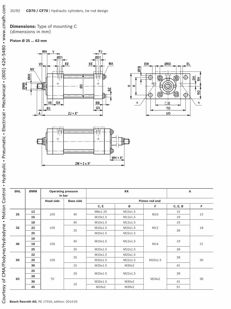
Dimensions: Type of mounting C (dimensions in mm)
Piston Ø 25 ... 63 mm
ØAL ØMM Operating pressure in bar
KK A
Head side Base side Piston rod end
C, E B F C, E, B F
2512
105 40M8x1.25 M10x1.5
M1015
1516 M10x1.5 M12x1.5 19
32
18
105
45 M10x1.5 M12x1.5
M12
19
182225
M16x1.5 M20x1.528
25 M20x1.5 M22x1.5
40
16
10545 M10x1.5 M12x1.5
M1419
2118
25 25 M20x1.5 M22x1.5 28
50
22
10525
M16x1.5 M20x1.5
M20x1.528
3025 M20x1.5 M22x1.5
36 15 M26x1.5 M30x2 41
63
25
70
20 M20x1.5 M22x1.5
M24x2
28
3628
3610
M26x1.5 M30x2 41
45 M33x2 M39x2 51
Court
esy
of CM
A/F
lodyn
e/H
ydra
dyn
e ▪
Motion C
ontr
ol ▪
Hyd
raulic
▪ P
neu
mat
ic ▪
Ele
ctrica
l ▪
Mec
han
ical
▪ (
800)
426-5
480 ▪
ww
w.c
maf
h.c
om

Hydraulic cylinders, tie rod design | CD70 / CG70 21/92
RE 17016, edition: 2014-03, Bosch Rexroth AG
Dimensions: Type of mounting C (dimensions in mm)
ØAL = Piston ØØMM = Piston rod ØX* = Stroke length1) Raised cylinder head and base 2) Raised cylinder head except for Ø 32/18 with end position
cushioning "U" or "K"
3) Raised cylinder head for: Ø 40/25; Ø 50/36 and Ø 63/45 with end position cushioning "D" or "S"
4) ØD1 max. 0.5 mm deep5) Adjustable throttle valve for the end position cushioning6) Check valve and bleeding7) Only with piston rod end "E" with double-acting cylinders
ØAL ØMM ØRD f7
NV B3 VE GA GV WH VD ØD ZJ ZM RO RH DH H R
2512 25.5 10
5.5 10 38 26 16 6.5 31 114 152 19 24 1) 5 38 27.516 28.5 13
32
18 32 14 5.5
10 38 26
16 6
38
115 153
22.5 35.5 2) 7 45 3222 34 198 25 13 124 171
25 38 22
40
16 28.5 135.5
10 38 2616 6
46118 156
25.5 38.5 3) 8 51 36.518 32 14
25 38 22 8 25 13 127 174
50
2238
198
10 38 2625 13
56127 174
31.5 44.5 3) 10 63 46.525 22
36 50 30 10 32 16 134 188
63
25 38 228
10 38 26
25 13
69
130 177
38 51 3) 15 76 55.528 42 24
36 50.7 30 10 32 16 137 191
45 60 41 12 38 19 143 203
ØAL ØMM EE ØD1 4) EW max.
E EL max.
Y PJ TO UO ØFB BB BZ MA
NmX* 7)
min.Line connection
01 02 01 02
2512
G 1/4 M14x1.5 25 25 12 38 7 33 11 51 63 6.5 6 M5 5.5 2516
32
18
G 1/4 M14x1.5 25 25 12 45 7 33 11 63 80 8.5 6 M5 5.5 2522
25
40
16
G 1/4 M14x1.5 25 25 9 51 4 33 11 70 85 8.5 6 M5 5.5 2518
25
50
22
G 1/4 M14x1.5 25 25 9 63 4 33 11 85.5 105 9.5 8 M8 23 3025
36
63
25
G 1/4 M14x1.5 25 25 6 76 1 33 11 98.5 115 9.5 8 M8 23 3028
36
45
Court
esy
of CM
A/F
lodyn
e/H
ydra
dyn
e ▪
Motion C
ontr
ol ▪
Hyd
raulic
▪ P
neu
mat
ic ▪
Ele
ctrica
l ▪
Mec
han
ical
▪ (
800)
426-5
480 ▪
ww
w.c
maf
h.c
om

��
��
��
��
�� �
���
���
��
��
����
�
��
����� �
���
�� ��
��
�
��
��
��
��
��
���
����� �
��������� �
����
��
���
����
22/92 CD70 / CF70 | Hydraulic cylinders, tie rod design
Bosch Rexroth AG, RE 17016, edition: 2014-03
Dimensions: Type of mounting C (dimensions in mm)
Piston Ø 80 ... 200 mm
ØAL ØMM Operating pressure in bar KK A
Head side Base side Piston rod end
C, E B F C, E, B F
80
36
7030
M26x1.5 M30x2
M30x2
41
4545 M33x2 M39x2 51
56 25 M39x2 M45x2 57
100
45
7025
M33x2 M39x2
M39x3
51
6550 M39x2 M45x2 57
70 15 M48x2 M56x2 76
125
50
70
15 M39x2 M45x2
M42x3
57
6556
6310
M48x2 M56x2 76
90 M64x2 M76x2 89
150
63
50
20 M48x2 M56x2
M45x3
76
6870
8015
M58x2 M68x2 89
100 M76x2 M95x2 101
200
90
‒ ‒ ‒ ‒ ‒ ‒ ‒100
140
Court
esy
of CM
A/F
lodyn
e/H
ydra
dyn
e ▪
Motion C
ontr
ol ▪
Hyd
raulic
▪ P
neu
mat
ic ▪
Ele
ctrica
l ▪
Mec
han
ical
▪ (
800)
426-5
480 ▪
ww
w.c
maf
h.c
om
Hydraulic cylinders, tie rod design | CD70 / CG70 23/92
RE 17016, edition: 2014-03, Bosch Rexroth AG
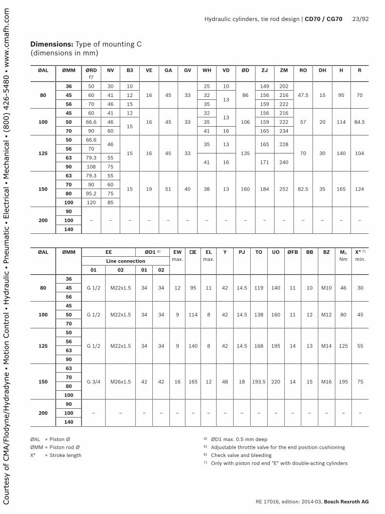
Dimensions: Type of mounting C (dimensions in mm)
ØAL = Piston Ø ØMM = Piston rod Ø X* = Stroke length
4) ØD1 max. 0.5 mm deep5) Adjustable throttle valve for the end position cushioning6) Check valve and bleeding7) Only with piston rod end "E" with double-acting cylinders
ØAL ØMM ØRD f7
NV B3 VE GA GV WH VD ØD ZJ ZM RO DH H R
80
36 50 30 10
16 45 33
25 10
86
149 202
47.5 15 95 7045 60 41 12 3213
156 216
56 70 46 15 35 159 222
100
45 60 41 12
16 45 33
3213
106
156 216
57 20 114 84.550 66.6 4615
35 159 222
70 90 60 41 16 165 234
125
50 66.646
15 16 45 33
35 13
135
165 228
70 30 140 10456 70
63 79.3 5541 16 171 240
90 108 75
150
63 79.3 55
15 19 51 40 38 13 160 184 252 82.5 35 165 12470 90 60
80 95.2 75
100 120 85
200
90
‒ ‒ ‒ ‒ ‒ ‒ ‒ ‒ ‒ ‒ ‒ ‒ ‒ ‒ ‒100
140
ØAL ØMM EE ØD1 4) EW max.
E EL max.
Y PJ TO UO ØFB BB BZ MA
NmX* 7)
min.Line connection
01 02 01 02
80
36
G 1/2 M22x1.5 34 34 12 95 11 42 14.5 119 140 11 10 M10 46 3045
56
100
45
G 1/2 M22x1.5 34 34 9 114 8 42 14.5 138 160 11 12 M12 80 4550
70
125
50
G 1/2 M22x1.5 34 34 9 140 8 42 14.5 168 195 14 13 M14 125 5556
63
90
150
63
G 3/4 M26x1.5 42 42 16 165 12 48 18 193.5 220 14 15 M16 195 7570
80
100
200
90
‒ ‒ ‒ ‒ ‒ ‒ ‒ ‒ ‒ ‒ ‒ ‒ ‒ ‒ ‒ ‒100
140
Court
esy
of CM
A/F
lodyn
e/H
ydra
dyn
e ▪
Motion C
ontr
ol ▪
Hyd
raulic
▪ P
neu
mat
ic ▪
Ele
ctrica
l ▪
Mec
han
ical
▪ (
800)
426-5
480 ▪
ww
w.c
maf
h.c
om

����
��
��
�� �
���
���
�� ��
����
�
��
����� �
���
��
��
��
�
��
��
��
��
����
���
����� �
��������� �
����
���
���
�����
��
24/92 CD70 / CF70 | Hydraulic cylinders, tie rod design
Bosch Rexroth AG, RE 17016, edition: 2014-03
Dimensions: Type of mounting H (dimensions in mm)
Piston Ø 25 ... 63 mm
ØAL ØMM Operating pressure in bar
KK A
Piston rod end
C, E B F C, E, B F
2512
105M8x1.25 M10x1.5
M1015
1516 M10x1.5 M12x1.5 19
32
18
105
M10x1.5 M12x1.5
M12
19
1822 M16x1.5 M20x1.528
25 M20x1.5 M22x1.5
40
16
105M10x1.5 M12x1.5
M1419
2118
25 M20x1.5 M22x1.5 28
50
22
105
M16x1.5 M20x1.5
M20x1.528
3025 M20x1.5 M22x1.5
36 M26x1.5 M30x2 41
63
25
70
M20x1.5 M22x1.5
M24x2
28
3628
36 M26x1.5 M30x2 41
45 M33x2 M39x2 51
Court
esy
of CM
A/F
lodyn
e/H
ydra
dyn
e ▪
Motion C
ontr
ol ▪
Hyd
raulic
▪ P
neu
mat
ic ▪
Ele
ctrica
l ▪
Mec
han
ical
▪ (
800)
426-5
480 ▪
ww
w.c
maf
h.c
om

Hydraulic cylinders, tie rod design | CD70 / CG70 25/92
RE 17016, edition: 2014-03, Bosch Rexroth AG
Dimensions: Type of mounting H (dimensions in mm)
ØAL = Piston ØØMM = Piston rod ØX* = Stroke length1) Raised cylinder head and base 2) Raised cylinder head except for Ø 32/18 with end position
cushioning "U" or "K"3) Raised cylinder head for: Ø 40/25; Ø 50/36 and Ø 63/45 with end
position cushioning "D" or "S"
4) ØD1 max. 0.5 mm deep5) Adjustable throttle valve for the end position cushioning6) Check valve and bleeding7) Only with piston rod end "E" with double-acting cylinders8) 6 usable mounting bores: With raised cylinder head.
With piston Ø 32 and 40 mm with line connection 13 or 14.
ØAL ØMM ØRD f7
NV B3 VE GA GV WH VD ØD ZJ ZM RO RH DH R
2512 25.5 10
5.5 10 38 26 16 6.5 31 114 152 19 24 1) 5 27.516 28.5 13
32
18 32 14 5.5
10 38 26
16 6
38
115 153
22.5 35.5 2) 7 3222 34 198 25 13 124 171
25 38 22
40
16 28.5 13 5.5
10 38 2616 6
46118 156
25.5 38.5 3) 8 36.518 32 148
25 38 22 25 13 127 174
50
2238
198
10 38 2625 13
56127 174
31.5 44.5 3) 10 46.525 22
36 50 30 10 32 16 134 188
63
25 38 228
10 38 26
25 13
69
130 177
38 51 3) 15 55.528 42 24
36 50.7 30 10 32 16 137 191
45 60 41 12 38 19 143 203
ØAL ØMM EE ØD1 4) EW max.
E EL max.
Y PJ TO UO ØFB BB BZ MA
NmX* 7)
min.Line connection
01 02 01 02
2512
G 1/4 M14x1.5 25 25 12 38 7 33 11 51 63 6.5 6 M5 5.5 2516
32
18
G 1/4 M14x1.5 25 25 12 45 7 33 11 63 80 8.5 6 M5 5.5 2522
25
40
16
G 1/4 M14x1.5 25 25 9 51 4 33 11 70 85 8.5 6 M5 5.5 2518
25
50
22
G 1/4 M14x1.5 25 25 9 63 4 33 11 85.5 105 9.5 8 M8 23 3025
36
63
25
G 1/4 M14x1.5 25 25 6 76 1 33 11 98.5 115 9.5 8 M8 23 3028
36
45
Court
esy
of CM
A/F
lodyn
e/H
ydra
dyn
e ▪
Motion C
ontr
ol ▪
Hyd
raulic
▪ P
neu
mat
ic ▪
Ele
ctrica
l ▪
Mec
han
ical
▪ (
800)
426-5
480 ▪
ww
w.c
maf
h.c
om

��
��
��
��
�� �
���
���
�� ��
����
�
��
����� �
���
��
��
��
�
��
��
��
��
��
���
����� �
��������� �
����
���
���
� �
�
����
�
��
�
��
���
����
26/92 CD70 / CF70 | Hydraulic cylinders, tie rod design
Bosch Rexroth AG, RE 17016, edition: 2014-03
Piston Ø 80 ... 200 mm
ØAL ØMM Operating pressure in bar
KK A
Piston rod end
C, E B F C, E, B F
80
36
70
M26x1.5 M30x2
M30x2
41
4545 M33x2 M39x2 51
56 M39x2 M45x2 57
100
45
70
M33x2 M39x2
M39x3
51
6550 M39x2 M45x2 57
70 M48x2 M56x2 76
125
50
70
M39x2 M45x2
M42x3
57
6556
63 M48x2 M56x2 76
90 M64x2 M76x2 89
150
63
50
M48x2 M56x2
M45x3
76
6870
80 M58x2 M68x2 89
100 M76x2 M95x2 101
200
90
40
M64x2 M76x2
M52x3
89
70100 M76x2 M95x2 101
140 M100x2 M130x2 140
Dimensions: Type of mounting H (dimensions in mm)
View "X" Only for piston Ø 200 mm
Court
esy
of CM
A/F
lodyn
e/H
ydra
dyn
e ▪
Motion C
ontr
ol ▪
Hyd
raulic
▪ P
neu
mat
ic ▪
Ele
ctrica
l ▪
Mec
han
ical
▪ (
800)
426-5
480 ▪
ww
w.c
maf
h.c
om

Hydraulic cylinders, tie rod design | CD70 / CG70 27/92
RE 17016, edition: 2014-03, Bosch Rexroth AG
Dimensions: Type of mounting H (dimensions in mm)
ØAL = Piston Ø ØMM = Piston rod ØX* = Stroke length
4) ØD1 max. 0.5 mm deep5) Adjustable throttle valve for the end position cushioning6) Check valve and bleeding7) Only with piston rod end "E" with double-acting cylinders
ØAL ØMM ØRD f7
NV B3 VE GA GV WH VD ØD ZJ ZM RO RH DH R
80
36 50 30 10
16 45 33
25 10
86
149 202
47.5 ‒ 15 7045 60 41 12 3213
156 216
56 70 46 15 35 159 222
100
45 60 41 12
16 45 33
3213
106
156 216
57 ‒ 20 84.550 66.6 4615
35 159 222
70 90 60 41 16 165 134
125
50 66.646
15 16 45 33
35
16 135
165 228
70 ‒ 30 10456 70
63 79.3 5541 171 240
90 108 75
150
63 79.3 55
15 19 51 40 38 13 160 184 252 82.5 ‒ 35 12470 90 60
80 95.2 75
100 120 85
200
90 108 75
15 19 51 40 38 13 215 187 255 108 ‒ 55 192.5100 120 85
140 158 120
ØAL ØMM EE ØD1 4) EW max.
E EL max.
Y PJ TO UO ØFB BB BZ B1 MA
NmX* 7)
min.Line connection
01 02 01 02
80
36
G 1/2 M22x1.5 34 34 12 95 11 42 14.5 119 140 11 10 M10 ‒ 46 3045
56
100
45
G 1/2 M22x1.5 34 34 9 114 8 42 14.5 138 160 11 12 M12 ‒ 80 4550
70
125
50
G 1/2 M22x1.5 34 34 9 140 8 42 14.5 168 195 14 13 M14 ‒ 125 5556
63
90
150
63
G 3/4 M26x1.5 42 42 16 165 12 48 18 193.5 220 14 15 M16 ‒ 195 7570
80
100
200
90
G 3/4 M26x1.5 42 42 14 216 10 48 18 192.5 ‒ 17.5 15 M16140
195 115100
140 178
Court
esy
of CM
A/F
lodyn
e/H
ydra
dyn
e ▪
Motion C
ontr
ol ▪
Hyd
raulic
▪ P
neu
mat
ic ▪
Ele
ctrica
l ▪
Mec
han
ical
▪ (
800)
426-5
480 ▪
ww
w.c
maf
h.c
om

��
��
�� �
���
���
��
�� ���
������
���
��
��
�� ��
���
��
���
��
�� ���
�� ��
����
��
����
��
���
����
28/92 CD70 / CF70 | Hydraulic cylinders, tie rod design
Bosch Rexroth AG, RE 17016, edition: 2014-03
Dimensions: Type of mounting D (dimensions in mm)
Piston Ø 25 ... 63 mm
ØAL ØMM Operating pressure in bar
KK A
Piston rod end
C, E B F C, E, B F
2512
105M8x1.25 M10x1.5
M1015
1516 M10x1.5 M12x1.5 19
32
18
105
M10x1.5 M12x1.5
M12
19
1822 M16x1.5 M20x1.528
25 M20x1.5 M22x1.5
40
16
105M10x1.5 M12x1.5
M1419
2118
25 M20x1.5 M22x1.5 28
50
22
105
M16x1.5 M20x1.5
M20x1.528
3025 M20x1.5 M22x1.5
36 M26x1.5 M30x2 41
63
25
70
M20x1.5 M22x1.5
M24x2
28
3628
36 M26x1.5 M30x2 41
45 M33x2 M39x2 51
Court
esy
of CM
A/F
lodyn
e/H
ydra
dyn
e ▪
Motion C
ontr
ol ▪
Hyd
raulic
▪ P
neu
mat
ic ▪
Ele
ctrica
l ▪
Mec
han
ical
▪ (
800)
426-5
480 ▪
ww
w.c
maf
h.c
om

Hydraulic cylinders, tie rod design | CD70 / CG70 29/92
RE 17016, edition: 2014-03, Bosch Rexroth AG
Dimensions: Type of mounting D (dimensions in mm)
ØAL = Piston ØØMM = Piston rod ØX* = Stroke length1) Raised cylinder head and base 2) Raised cylinder head except for Ø 32/18 with end position
cushioning "U" or "K"
3) Raised cylinder head for: Ø 40/25; Ø 50/36 and Ø 63/45 with end position cushioning "D" or "S"
4) ØD1 max. 0.5 mm deep5) Adjustable throttle valve for the end position cushioning6) Check valve and bleeding
ØAL ØMM ØRDf7
NV B3 VE GA GV WH VD ØD VB ZF RO RH DH H R
2512 25.5 10
5.5 10 38 26 16 6.5 31 10 124 19 24 1) 5 38 27.516 28.5 13
32
18 32 14 5.5
10 38 26
16 6
38 10
125
22.5 35.5 2) 7 45 3222 34 198 25 13 134
25 38 22
40
16 28.5 135.5
10 38 2616 6
46 9127
25.5 38.5 3) 8 51 36.518 32 14
25 38 22 8 25 13 136
50
2238
198
10 38 2625 13
56 9136
31.5 44.5 3) 10 63 46.525 22
36 50 30 10 32 16 143
63
25 28 228
10 38 26
25 13
69 10
140
38 51 3) 15 76 55.528 42 24
36 50.7 30 10 32 16 147
45 60 41 12 38 19 153
ØAL ØMM EE ØD1 4) EW max.
E EL max.
Y PJ TO UO ØFB BB BZ MA
NmLine connection
01 02 01 02
2512
G 1/4 M14x1.5 25 25 12 38 7 33 11 51 63 6.5 6 M5 5.516
32
18
G 1/4 M14x1.5 25 25 12 45 7 33 11 63 80 8.5 6 M5 5.522
25
40
16
G 1/4 M14x1.5 25 25 9 51 4 33 11 70 85 8.5 6 M5 5.518
25
50
22
G 1/4 M14x1.5 25 25 9 63 4 33 11 85.5 105 9.5 8 M8 2325
36
63
25
G 1/4 M14x1.5 25 25 6 76 1 33 11 98.5 115 9.5 8 M8 2328
36
45
Court
esy
of CM
A/F
lodyn
e/H
ydra
dyn
e ▪
Motion C
ontr
ol ▪
Hyd
raulic
▪ P
neu
mat
ic ▪
Ele
ctrica
l ▪
Mec
han
ical
▪ (
800)
426-5
480 ▪
ww
w.c
maf
h.c
om
��
��
�� �
���
���
��
�� ���
������
���
��
��
�� ��
���
��
���
��
�� ���
��
����
��
����
��
���
����
30/92 CD70 / CF70 | Hydraulic cylinders, tie rod design
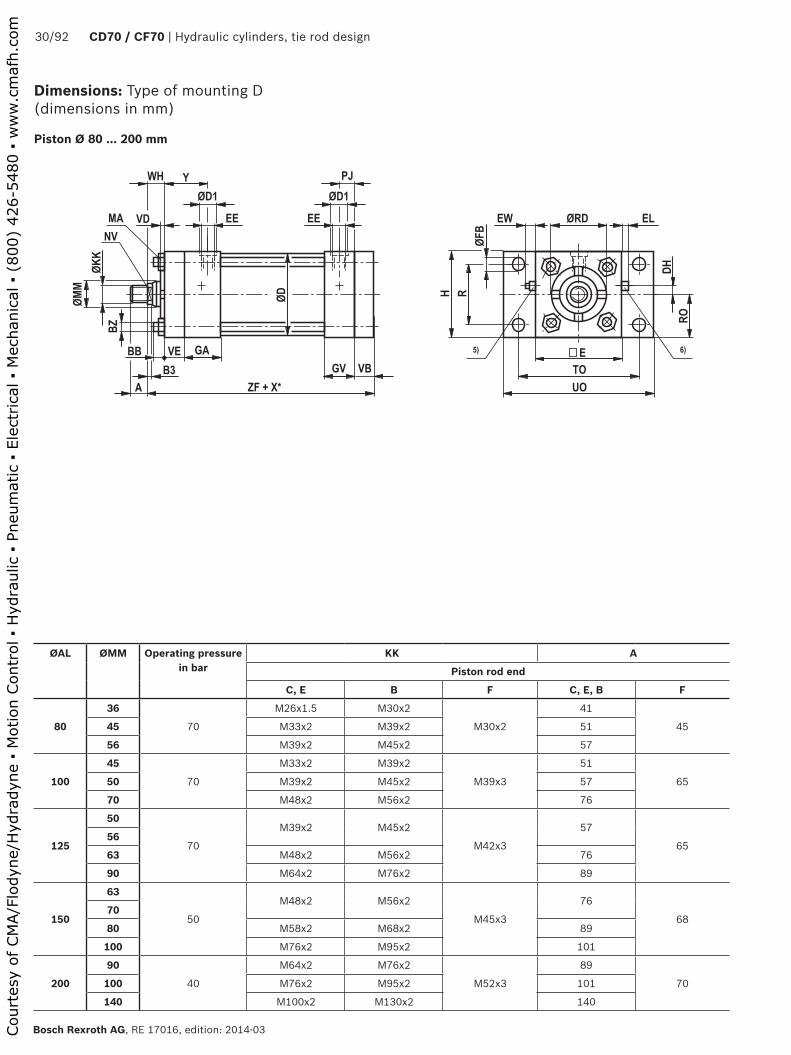
Bosch Rexroth AG, RE 17016, edition: 2014-03
Piston Ø 80 ... 200 mm
ØAL ØMM Operating pressure in bar
KK A
Piston rod end
C, E B F C, E, B F
80
36
70
M26x1.5 M30x2
M30x2
41
4545 M33x2 M39x2 51
56 M39x2 M45x2 57
100
45
70
M33x2 M39x2
M39x3
51
6550 M39x2 M45x2 57
70 M48x2 M56x2 76
125
50
70
M39x2 M45x2
M42x3
57
6556
63 M48x2 M56x2 76
90 M64x2 M76x2 89
150
63
50
M48x2 M56x2
M45x3
76
6870
80 M58x2 M68x2 89
100 M76x2 M95x2 101
200
90
40
M64x2 M76x2
M52x3
89
70100 M76x2 M95x2 101
140 M100x2 M130x2 140
Dimensions: Type of mounting D (dimensions in mm)
Court
esy
of CM
A/F
lodyn
e/H
ydra
dyn
e ▪
Motion C
ontr
ol ▪
Hyd
raulic
▪ P
neu
mat
ic ▪
Ele
ctrica
l ▪
Mec
han
ical
▪ (
800)
426-5
480 ▪
ww
w.c
maf
h.c
om

Hydraulic cylinders, tie rod design | CD70 / CG70 31/92
RE 17016, edition: 2014-03, Bosch Rexroth AG
Dimensions: Type of mounting D (dimensions in mm)
ØAL = Piston ØØMM = Piston rod ØX* = Stroke length
4) ØD1 max. 0.5 mm deep5) Adjustable throttle valve for the end position cushioning6) Check valve and bleeding
ØAL ØMM ØRDf7
NV B3 VE GA GV WH VD ØD VB ZF RO DH H R
80
36 50 30 10
16 45 33
25 10
86 16
165
47.5 15 95 7045 60 41 12 3213
172
56 70 46 15 35 175
100
45 60 41 12
16 45 33
32 13
106 16
172
57 20 114 84.550 66.6 4615
3516
175
70 90 60 41 181
125
50 66.646
15 16 45 33
35 13
135 16
181
70 30 140 10456 70
63 79.3 5541 16 187
90 108 75
150
63 79.3 55
15 19 51 40 38 13 160 19 203 82.5 35 165 12470 90 60
80 95.2 75
100 120 85
200
90
‒ ‒ ‒ ‒ ‒ ‒ ‒ ‒ ‒ ‒ ‒ ‒ ‒ ‒ ‒100
140
ØAL ØMM EE ØD1 4) EW max.
E EL max.
Y PJ TO UO ØFB BB BZ MA
NmLine connection
01 02 01 02
80
36
G 1/2 M22x1.5 34 34 12 95 11 42 14.5 119 140 11 10 M10 4645
56
100
45
G 1/2 M22x1.5 34 34 9 114 8 42 14.5 138 160 11 12 M12 8050
70
125
50
G 1/2 M22x1.5 34 34 9 140 8 42 14.5 168 195 14 13 M14 12556
63
90
150
63
G 3/4 M26x1.5 42 42 16 165 12 48 18 193.5 220 14 15 M16 19570
80
100
200
90
‒ ‒ ‒ ‒ ‒ ‒ ‒ ‒ ‒ ‒ ‒ ‒ ‒ ‒ ‒100
140
Court
esy
of CM
A/F
lodyn
e/H
ydra
dyn
e ▪
Motion C
ontr
ol ▪
Hyd
raulic
▪ P
neu
mat
ic ▪
Ele
ctrica
l ▪
Mec
han
ical
▪ (
800)
426-5
480 ▪
ww
w.c
maf
h.c
om
��
��
�� �
���
���
��
�� ��
�������
�
��
��
�� ��
���
��
���
��
�
��� ����
�
����
��
����
���
���
�����
��
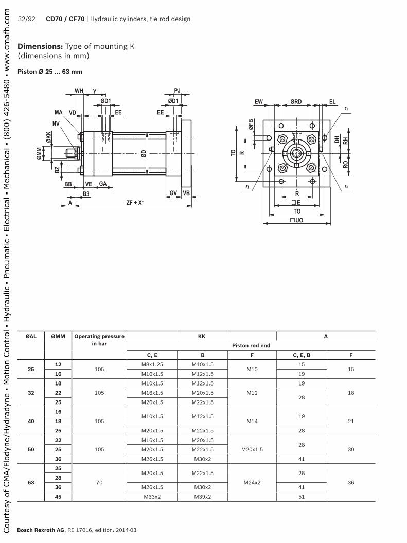
32/92 CD70 / CF70 | Hydraulic cylinders, tie rod design
Bosch Rexroth AG, RE 17016, edition: 2014-03
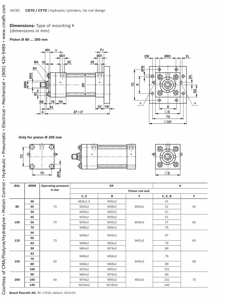
Dimensions: Type of mounting K (dimensions in mm)
Piston Ø 25 ... 63 mm
ØAL ØMM Operating pressure in bar
KK A
Piston rod end
C, E B F C, E, B F
2512
105M8x1.25 M10x1.5
M1015
1516 M10x1.5 M12x1.5 19
32
18
105
M10x1.5 M12x1.5
M12
19
1822 M16x1.5 M20x1.528
25 M20x1.5 M22x1.5
40
16
105M10x1.5 M12x1.5
M1419
2118
25 M20x1.5 M22x1.5 28
50
22
105
M16x1.5 M20x1.5
M20x1.528
3025 M20x1.5 M22x1.5
36 M26x1.5 M30x2 41
63
25
70
M20x1.5 M22x1.5
M24x2
28
3628
36 M26x1.5 M30x2 41
45 M33x2 M39x2 51
Court
esy
of CM
A/F
lodyn
e/H
ydra
dyn
e ▪
Motion C
ontr
ol ▪
Hyd
raulic
▪ P
neu
mat
ic ▪
Ele
ctrica
l ▪
Mec
han
ical
▪ (
800)
426-5
480 ▪
ww
w.c
maf
h.c
om

Hydraulic cylinders, tie rod design | CD70 / CG70 33/92
RE 17016, edition: 2014-03, Bosch Rexroth AG
Dimensions: Type of mounting K (dimensions in mm)
ØAL = Piston ØØMM = Piston rod ØX* = Stroke length1) Raised cylinder head and base2) Raised cylinder head except for Ø 32/18 with end position
cushioning "U" or "K"
3) Raised cylinder head for: Ø 40/25; Ø 50/36 and Ø 63/45 with end position cushioning "D" or "S"
4) ØD1 max. 0.5 mm deep5) Adjustable throttle valve for the end position cushioning6) Check valve and bleeding 7) 6 usable mounting bores with raised cylinder base
ØAL ØMM ØRDf7
NV B3 VE GA GV WH VD ØD VB ZF RO RH DH R
2512 25.5 10
5.5 10 38 26 16 6.5 31 10 124 19 24 1) 5 27.516 28.5 13
32
18 32 14 5.5
10 38 26
16 6
38 10
125
22.5 35.5 2) 7 3222 34 198 25 13 134
25 38 22
40
16 28.5 135.5
10 38 2616 6
46 9127
25.5 38.5 3) 8 36.518 32 14
25 38 22 8 25 13 136
50
2238
198
10 38 2625 13
56 9136
31.5 44.5 3) 10 46.525 22
36 50 30 10 32 16 143
63
25 38 228
10 38 26
25 13
69 10
140
38 51 3) 15 55.528 42 24
36 50.7 30 10 32 16 147
45 60 41 12 38 19 153
ØAL ØMM EE ØD1 4) EW max.
E EL max.
Y PJ TO UO ØFB BB BZ MA
NmLine connection
01 02 01 02
2512
G 1/4 M14x1.5 25 25 12 38 7 33 11 51 63 6.5 6 M5 5.516
32
18
G 1/4 M14x1.5 25 25 12 45 7 33 11 63 80 8.5 6 M5 5.522
25
40
16
G 1/4 M14x1.5 25 25 9 51 4 33 11 70 85 8.5 6 M5 5.518
25
50
22
G 1/4 M14x1.5 25 25 9 63 4 33 11 85.5 105 9.5 8 M8 2325
36
63
25
G 1/4 M14x1.5 25 25 6 76 1 33 11 98.5 115 9.5 8 M8 2328
36
45
Court
esy
of CM
A/F
lodyn
e/H
ydra
dyn
e ▪
Motion C
ontr
ol ▪
Hyd
raulic
▪ P
neu
mat
ic ▪
Ele
ctrica
l ▪
Mec
han
ical
▪ (
800)
426-5
480 ▪
ww
w.c
maf
h.c
om
��
��
�� �
���
���
��
�� ��
�������
�
��
��
�� ��
���
��
���
��
�
��� ����
�
����
����
���
���
�
��
��
��� �
����
34/92 CD70 / CF70 | Hydraulic cylinders, tie rod design
Bosch Rexroth AG, RE 17016, edition: 2014-03
Piston Ø 80 ... 200 mm
ØAL ØMM Operating pressure in bar
KK A
Piston rod end
C, E B F C, E, B F
80
36
70
M26x1.5 M30x2
M30x2
41
4545 M33x2 M39x2 51
56 M39x2 M45x2 57
100
45
70
M33x2 M39x2
M39x3
51
6550 M39x2 M45x2 57
70 M48x2 M56x2 76
125
50
70
M39x2 M45x2
M42x3
57
6556
63 M48x2 M56x2 76
90 M64x2 M76x2 89
150
63
50
M48x2 M56x2
M45x3
76
6870
80 M58x2 M68x2 89
100 M76x2 M95x2 101
200
90
40
M64x2 M76x2
M52x3
89
70100 M76x2 M95x2 101
140 M100x2 M130x2 140
Dimensions: Type of mounting K (dimensions in mm)
Only for piston Ø 200 mm
Court
esy
of CM
A/F
lodyn
e/H
ydra
dyn
e ▪
Motion C
ontr
ol ▪
Hyd
raulic
▪ P
neu
mat
ic ▪
Ele
ctrica
l ▪
Mec
han
ical
▪ (
800)
426-5
480 ▪
ww
w.c
maf
h.c
om

Hydraulic cylinders, tie rod design | CD70 / CG70 35/92
RE 17016, edition: 2014-03, Bosch Rexroth AG
Dimensions: Type of mounting K (dimensions in mm)
ØAL = Piston ØØMM = Piston rod ØX* = Stroke length
4) ØD1 max. 0.5 mm deep5) Adjustable throttle valve for the end position cushioning6) Check valve and bleeding
ØAL ØMM ØRDf7
NV B3 VE GA GV WH VD ØD VB ZF RO DH R
80
36 50 30 10
16 45 33
25 10
86 16
165
47.5 15 7045 60 41 12 3213
172
56 70 46 15 35 175
100
45 60 41 12
16 45 33
3213
106 16
172
57 20 84.550 66.6 4615
35 175
70 90 60 41 16 181
125
50 66.646
15 16 45 33
35 13
135 16
181
70 30 10456 70
63 79.3 5541 16 187
90 108 75
150
63 79.3 55
15 19 51 40 38 13 160 19 203 82.5 35 12470 90 60
80 95.2 75
100 120 85
200
90 108 75
15 19 51 40 38 13 215 ‒ 187 108 55 ‒100 120 85
140 158 120
ØAL ØMM EE ØD1 4) EW max.
E EL max.
Y PJ TO UO ØFB BB BZ MA
NmLine connection
01 02 01 02
80
36
G 1/2 M22x1.5 34 34 12 95 11 42 14.5 119 140 11 10 M10 4645
56
100
45
G 1/2 M22x1.5 34 34 9 114 8 42 14.5 138 160 11 12 M12 8050
70
125
50
G 1/2 M22x1.5 34 34 9 140 8 42 14.5 168 195 14 13 M14 12556
63
90
150
63
G 3/4 M26x1.5 42 42 16 165 12 48 18 193.5 220 14 15 M16 19570
80
100
200
90
G 3/4 M26x1.5 42 42 14 216 10 48 18 192.5 ‒ 17.5 15 M16 195100
140
Court
esy
of CM
A/F
lodyn
e/H
ydra
dyn
e ▪
Motion C
ontr
ol ▪
Hyd
raulic
▪ P
neu
mat
ic ▪
Ele
ctrica
l ▪
Mec
han
ical
▪ (
800)
426-5
480 ▪
ww
w.c
maf
h.c
om

����
��
��
�� �
���
���
��
�� ���� ��
��
�
���
��
��
�� ��
���
��
���
��
��
����
���
���� �
����
��
��
��������� �
� ����� �
����
36/92 CD70 / CF70 | Hydraulic cylinders, tie rod design
Bosch Rexroth AG, RE 17016, edition: 2014-03
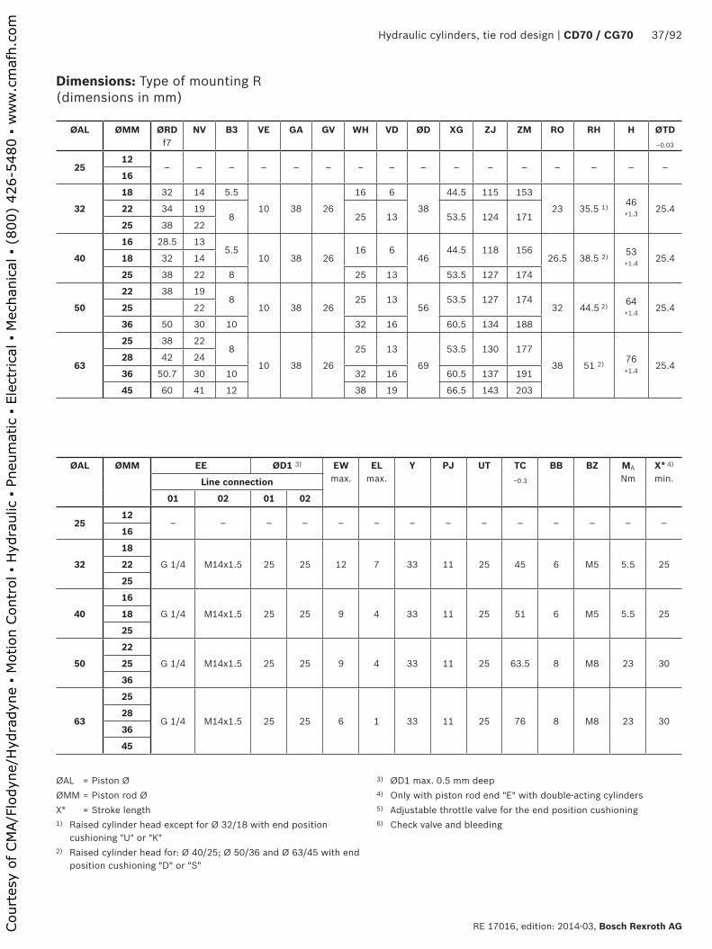
Dimensions: Type of mounting R (dimensions in mm)
Piston Ø 25 ... 63 mm
ØAL ØMM Operating pressure in bar
KK A
Piston rod end
C, E B F C, E, B F
2512
‒ ‒ ‒ ‒ ‒ ‒16
32
18
105
M10x1.5 M12x1.5
M12
19
1822 M16x1.5 M20x1.528
25 M20x1.5 M22x1.5
40
16
105M10x1.5 M12x1.5
M1419
2118
25 M20x1.5 M22x1.5 28
50
22
105
M16x1.5 M20x1.5
M20x1.528
3025 M20x1.5 M22x1.5
36 M26x1.5 M30x2 41
63
25
70
M20x1.5 M22x1.5
M24x2
28
3628
36 M26x1.5 M30x2 41
45 M33x2 M39x2 51
Court
esy
of CM
A/F
lodyn
e/H
ydra
dyn
e ▪
Motion C
ontr
ol ▪
Hyd
raulic
▪ P
neu
mat
ic ▪
Ele
ctrica
l ▪
Mec
han
ical
▪ (
800)
426-5
480 ▪
ww
w.c
maf
h.c
om
Hydraulic cylinders, tie rod design | CD70 / CG70 37/92
RE 17016, edition: 2014-03, Bosch Rexroth AG
Dimensions: Type of mounting R (dimensions in mm)
ØAL = Piston ØØMM = Piston rod ØX* = Stroke length1) Raised cylinder head except for Ø 32/18 with end position
cushioning "U" or "K"2) Raised cylinder head for: Ø 40/25; Ø 50/36 and Ø 63/45 with end
position cushioning "D" or "S"
3) ØD1 max. 0.5 mm deep4) Only with piston rod end "E" with double-acting cylinders5) Adjustable throttle valve for the end position cushioning6) Check valve and bleeding
ØAL ØMM ØRDf7
NV B3 VE GA GV WH VD ØD XG ZJ ZM RO RH H ØTD‒0.03
2512
‒ ‒ ‒ ‒ ‒ ‒ ‒ ‒ ‒ ‒ ‒ ‒ ‒ ‒ ‒ ‒16
32
18 32 14 5.5
10 38 26
16 6
38
44.5 115 153
23 35.5 1) 46 +1.3 25.422 34 19
8 25 13 53.5 124 17125 38 22
40
16 28.5 135.5
10 38 2616 6
4644.5 118 156
26.5 38.5 2) 53 +1.4 25.418 32 14
25 38 22 8 25 13 53.5 127 174
50
22 38 198
10 38 2625 13
5653.5 127 174
32 44.5 2) 64 +1.4 25.425 22
36 50 30 10 32 16 60.5 134 188
63
25 38 228
10 38 26
25 13
69
53.5 130 177
38 51 2) 76 +1.4 25.4
28 42 24
36 50.7 30 10 32 16 60.5 137 191
45 60 41 12 38 19 66.5 143 203
ØAL ØMM EE ØD1 3) EW max.
EL max.
Y PJ UT TC‒0.3
BB BZ MA
NmX* 4)
min.Line connection
01 02 01 02
2512
‒ ‒ ‒ ‒ ‒ ‒ ‒ ‒ ‒ ‒ ‒ ‒ ‒ ‒16
32
18
G 1/4 M14x1.5 25 25 12 7 33 11 25 45 6 M5 5.5 2522
25
40
16
G 1/4 M14x1.5 25 25 9 4 33 11 25 51 6 M5 5.5 2518
25
50
22
G 1/4 M14x1.5 25 25 9 4 33 11 25 63.5 8 M8 23 3025
36
63
25
G 1/4 M14x1.5 25 25 6 1 33 11 25 76 8 M8 23 3028
36
45
Court
esy
of CM
A/F
lodyn
e/H
ydra
dyn
e ▪
Motion C
ontr
ol ▪
Hyd
raulic
▪ P
neu
mat
ic ▪
Ele
ctrica
l ▪
Mec
han
ical
▪ (
800)
426-5
480 ▪
ww
w.c
maf
h.c
om

����
��
��
�� �
���
���
��
�� ���� ��
��
�
���
��
��
�� ��
���
��
���
��
��
��
���
���� �
����
��
��
��������� �
� ����� �
����
38/92 CD70 / CF70 | Hydraulic cylinders, tie rod design
Bosch Rexroth AG, RE 17016, edition: 2014-03
Piston Ø 80 ... 200 mm
ØAL ØMM Operating pressure in bar
KK A
Piston rod end
C, E B F C, E, B F
80
36
70
M26x1.5 M30x2
M30x2
41
4545 M33x2 M39x2 51
56 M39x2 M45x2 57
100
45
70
M33x2 M39x2
M39x3
51
6550 M39x2 M45x2 57
70 M48x2 M56x2 76
125
50
70
M39x2 M45x2
M42x3
57
6556
63 M48x2 M56x2 76
90 M64x2 M76x2 89
150
63
50
M48x2 M56x2
M45x3
766870
80 M58x2 M68x2 89
100 M76x2 M95x2 101
70200
90
40
M64x2 M76x2
M52x3
89
100 M76x2 M95x2 101
140 M100x2 M130x2 140
Dimensions: Type of mounting R (dimensions in mm)
Court
esy
of CM
A/F
lodyn
e/H
ydra
dyn
e ▪
Motion C
ontr
ol ▪
Hyd
raulic
▪ P
neu
mat
ic ▪
Ele
ctrica
l ▪
Mec
han
ical
▪ (
800)
426-5
480 ▪
ww
w.c
maf
h.c
om

Hydraulic cylinders, tie rod design | CD70 / CG70 39/92
RE 17016, edition: 2014-03, Bosch Rexroth AG
Dimensions: Type of mounting R (dimensions in mm)
ØAL = Piston ØØMM = Piston rod ØX* = Stroke length
3) ØD1 max. 0.5 mm deep4) Only with piston rod end "E" with double-acting cylinders5) Adjustable throttle valve for the end position cushioning6) Check valve and bleeding
ØAL ØMM ØRDf7
NV B3 VE GA GV WH VD ØD XG ZJ ZM RO H ØTD‒0.03
80
36 50 30 10
16 45 33
25 10
86
63.5 149 202
47.595 +1.5 25.445 60 41 12 32
1370.5 156 216
56 70 46 15 35 73.5 159 222
100
45 60 41 12
16 45 33
3213
106
70 156 216
57114 +1.5 25.450 66.6 46
1535 73 159 222
70 90 60 41 16 79 165 234
125
50 66.646
15 16 45 33
35 13
135
73 165 228
70140 +1.6 25.4
56 70
63 79.3 5541 16 79 171 240
90 108 75
150
63 79.3 55
15 19 51 40 38 13 160 82.5 184 252 82.5165 +1.6 34.92
70 90 60
80 95.2 75
100 120 85
200
90 108 75
15 19 51 40 38 13 215 82.5 187 255 108216 +1.8 34.92100 120 85
140 158 120
ØAL ØMM EE ØD1 3) EW max.
EL max.
Y PJ UT TC‒0.3
BB BZ MA
NmX* 4)
min.Line connection
01 02 01 02
80
36
G 1/2 M22x1.5 34 34 12 11 42 14.5 25 95 10 M10 46 3045
56
100
45
G 1/2 M22x1.5 34 34 9 8 42 14.5 25 114 12 M12 80 4550
70
125
50
G 1/2 M22x1.5 34 34 9 8 42 14.5 25 140 13 M14 125 5556
63
90
150
63
G 3/4 M26x1.5 42 42 16 12 48 18 35 165 15 M16 195 7570
80
100
200
90
G 3/4 M26x1.5 42 42 14 10 48 18 35 216 15 M16 195 115100
140
Court
esy
of CM
A/F
lodyn
e/H
ydra
dyn
e ▪
Motion C
ontr
ol ▪
Hyd
raulic
▪ P
neu
mat
ic ▪
Ele
ctrica
l ▪
Mec
han
ical
▪ (
800)
426-5
480 ▪
ww
w.c
maf
h.c
om
����
��
��
�� �
���
���
���� ���� ��
��
���
�
��
��
�� ��
���
��
��
���
��
�
����
���
����� �
���
��
��
�������� �
��� ����� �
��
��
��
�������������
40/92 CD70 / CF70 | Hydraulic cylinders, tie rod design
Bosch Rexroth AG, RE 17016, edition: 2014-03
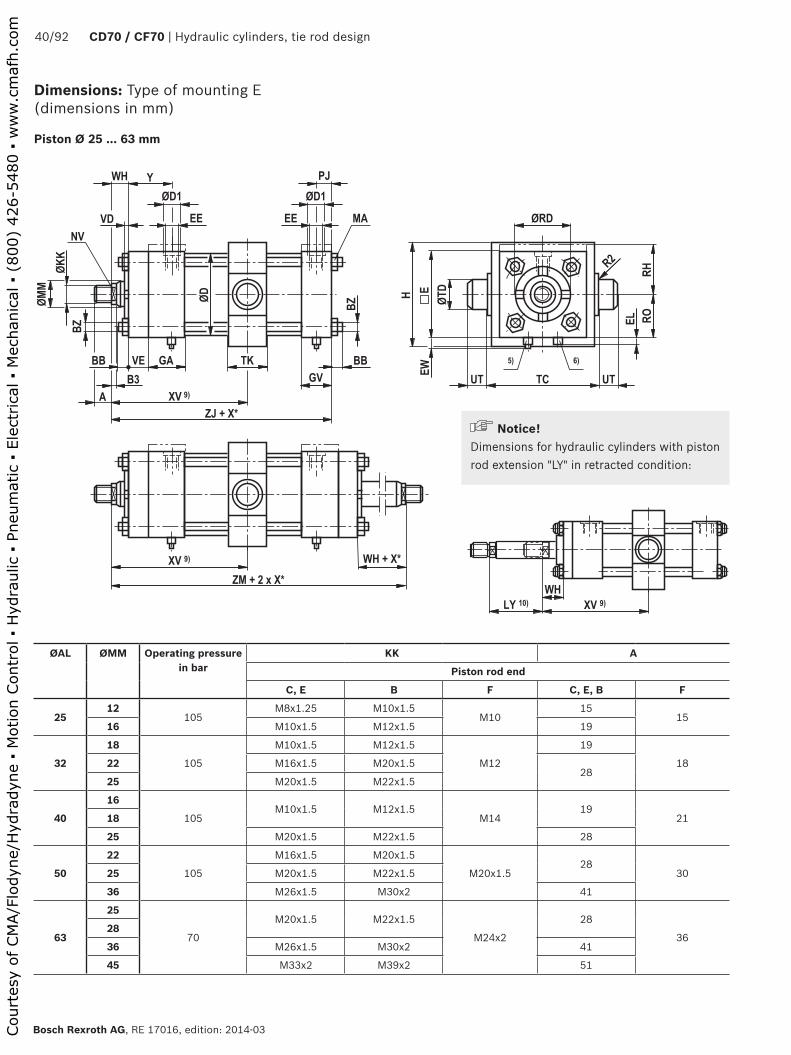
Dimensions: Type of mounting E (dimensions in mm)
Piston Ø 25 ... 63 mm
ØAL ØMM Operating pressure in bar
KK A
Piston rod end
C, E B F C, E, B F
2512
105M8x1.25 M10x1.5
M1015
1516 M10x1.5 M12x1.5 19
32
18
105
M10x1.5 M12x1.5
M12
19
1822 M16x1.5 M20x1.528
25 M20x1.5 M22x1.5
40
16
105M10x1.5 M12x1.5
M1419
2118
25 M20x1.5 M22x1.5 28
50
22
105
M16x1.5 M20x1.5
M20x1.528
3025 M20x1.5 M22x1.5
36 M26x1.5 M30x2 41
63
25
70
M20x1.5 M22x1.5
M24x2
28
3628
36 M26x1.5 M30x2 41
45 M33x2 M39x2 51
Notice!Dimensions for hydraulic cylinders with piston rod extension "LY" in retracted condition:
Court
esy
of CM
A/F
lodyn
e/H
ydra
dyn
e ▪
Motion C
ontr
ol ▪
Hyd
raulic
▪ P
neu
mat
ic ▪
Ele
ctrica
l ▪
Mec
han
ical
▪ (
800)
426-5
480 ▪
ww
w.c
maf
h.c
om

Hydraulic cylinders, tie rod design | CD70 / CG70 41/92
RE 17016, edition: 2014-03, Bosch Rexroth AG
Dimensions: Type of mounting E (dimensions in mm)
ØAL = Piston ØØMM = Piston rod ØX* = Stroke length1) Raised cylinder head and base 2) Raised cylinder head except for Ø 32/18 with end position
cushioning "U" or "K"3) Raised cylinder head for: Ø 40/25; Ø 50/36 and Ø 63/45 with end
position cushioning "D" or "S"4) ØD1 max. 0.5 mm deep
5) Adjustable throttle valve for the end position cushioning6) Check valve and bleeding7) Except for piston rod end "E" with double-acting cylinders8) Only with piston rod end "E" with double-acting cylinders9) Trunnion position freely selectable.
When ordering, always specify the "XV" dimension in the plain text in mm. With piston Ø 25, the trunnions are at the cylinder head
10) Always specify the piston rod extension "LY" in the order in the plain text
ØAL ØMM ØRDf7
NV B3 VE GA GV WH VD ØD XV 9)
min.XV 9)
max.ZJ ZM TK RO RH H
25 5)12 25.5 10
5.5 10 38 26 16 6.5 31 44.5 ‒ 114 152 ‒ 19 24 1) ‒16 28.5 13
32
18 32 14 5.5
10 38 26
16 6
38
80 73+X* 115 153
32 22.5 35.5 2) ‒22 34 198 25 13 89 82+X* 124 171
25 38 22
40
16 28.5 135.5
10 38 2616 6
4680 76+X* 118 156
32 25.5 38.5 3) 65 +1.418 32 14
25 38 22 8 25 13 89 85+X* 127 174
50
2238
198
10 38 2625 13
5692 82+X* 127 174
38 31.5 44.5 3) 75 +1.425 22
36 50 30 10 32 16 99 89+X* 134 188
63
25 38 228
10 38 26
25 13
69
92 85+X* 130 177
38 38 51 3) 90 +1.5
28 42 24
36 50.7 30 10 32 16 99 92+X* 137 191
45 60 41 12 38 19 105 98+X* 143 203
ØAL ØMM EE ØD1 4) EW max.
E EL max.
Y PJ ØTD‒0.03
UT TC‒0.3
BB BZ MA
NmX*
min. 7)
X*
min. 8)
Line connection
01 02 01 02
2512
G 1/4 M14x1.5 25 25 12 38 7 33 11 19.05 19 38 6 M5 5.5 ‒ 2516
32
18
G 1/4 M14x1.5 25 25 12 45 7 33 11 25.4 25 50 6 M5 5.5 10 2522
25
40
16
G 1/4 M14x1.5 25 25 9 51 4 33 11 25.4 25 63.5 6 M5 5.5 10 2518
25
50
22
G 1/4 M14x1.5 25 25 9 63 4 33 11 25.4 25 76 8 M8 23 10 3025
36
63
25
G 1/4 M14x1.5 25 25 6 76 1 33 11 25.4 25 89 8 M8 23 10 3028
36
45
Court
esy
of CM
A/F
lodyn
e/H
ydra
dyn
e ▪
Motion C
ontr
ol ▪
Hyd
raulic
▪ P
neu
mat
ic ▪
Ele
ctrica
l ▪
Mec
han
ical
▪ (
800)
426-5
480 ▪
ww
w.c
maf
h.c
om

����
��
��
�� �
���
���
���� ���� ��
��
���
�
��
��
�� ��
���
��
��
���
��
�
��
���
����� �
���
��
��
�������� �
��� ����� �
��
��
��
�������������
42/92 CD70 / CF70 | Hydraulic cylinders, tie rod design
Bosch Rexroth AG, RE 17016, edition: 2014-03
Notice!Dimensions for hydraulic cylinders with piston rod extension "LY" in retracted condition:
Piston Ø 80 ... 200 mm
ØAL ØMM Operating pressure in bar
KK A
Piston rod end
C, E B F C, E, B F
80
36
70
M26x1.5 M30x2
M30x2
41
4545 M33x2 M39x2 51
56 M39x2 M45x2 57
100
45
70
M33x2 M39x2
M39x3
51
6550 M39x2 M45x2 57
70 M48x2 M56x2 76
125
50
70
M39x2 M45x2
M42x3
57
6556
63 M48x2 M56x2 76
90 M64x2 M76x2 89
150
63
50
M48x2 M56x2
M45x3
76
6870
80 M58x2 M68x2 89
100 M76x2 M95x2 101
200
90
40
M64x2 M76x2
M52x3
89
70100 M76x2 M95x2 101
140 M100x2 M130x2 140
Dimensions: Type of mounting E (dimensions in mm)
Court
esy
of CM
A/F
lodyn
e/H
ydra
dyn
e ▪
Motion C
ontr
ol ▪
Hyd
raulic
▪ P
neu
mat
ic ▪
Ele
ctrica
l ▪
Mec
han
ical
▪ (
800)
426-5
480 ▪
ww
w.c
maf
h.c
om

Hydraulic cylinders, tie rod design | CD70 / CG70 43/92
RE 17016, edition: 2014-03, Bosch Rexroth AG
Dimensions: Type of mounting E (dimensions in mm)
ØAL = Piston ØØMM = Piston rod ØX* = Stroke length4) ØD1 max. 0.5 mm deep5) Adjustable throttle valve for the end position cushioning6) Check valve and bleeding7) Except for piston rod end "E" with double-acting cylinders
8) Only with piston rod end "E" with double-acting cylinders9) Trunnion position freely selectable.
When ordering, always specify the "XV" dimension in the plain text in mm. With piston Ø 25, the trunnions are at the cylinder head.
10) Always specify the piston rod extension "LY" in the order in the plain text
ØAL ØMM ØRDf7
NV B3 VE GA GV WH VD ØD XV 9)
min.XV 9)
max.ZJ ZM TK RO H
80
36 50 30 10
16 45 33
25 10
86
111 91+X* 149 202
50 47.5115 +1.545 60 41 12 32
13118 98+X* 156 216
56 70 46 15 35 121 101+X* 159 222
100
45 60 41 12
16 45 33
3213
106
118 98+X* 156 216
50 57135 +1.650 66.6 46
1535 121 101+X* 159 222
70 90 60 41 16 127 107+X* 165 234
125
50 66.646
15 16 45 33
35 13
135
121 107+X* 165 228
50 70160 +1.6
56 70
63 79.3 5541 16 127 113+X* 171 240
90 108 75
150
63 79.3 55
15 19 51 40 38 13 160 140 112+X* 184 252 64 82.5195 +1.8
70 90 60
80 95.2 75
100 120 85
200
90 108 75
15 19 51 40 38 13 215 140 115+X* 187 255 64 108250 +1.8100 120 85
140 158 120
ØAL ØMM EE ØD1 4) EW max.
E EL max.
Y PJ ØTD‒0.03
UT TC‒0.3
BB BZ MA
NmX*
min. 7)
X*
min. 8)
Line connection
01 02 01 02
80
36
G 1/2 M22x1.5 34 34 12 95 11 42 15 25.4 25 114 10 M10 46 20 3045
56
100
45
G 1/2 M22x1.5 34 34 9 114 8 42 15 25.4 25 133 12 M12 80 20 4550
70
125
50
G 1/2 M22x1.5 34 34 9 140 8 42 15 25.4 25 159 13 M14 125 20 5556
63
90
150
63
G 3/4 M26x1.5 42 42 16 165 12 48 18 34.92 35 194 15 M16 195 30 7570
80
100
200
90
G 3/4 M26x1.5 42 42 14 216 10 48 18 34.92 35 248 15 M16 195 30 115100
140
Court
esy
of CM
A/F
lodyn
e/H
ydra
dyn
e ▪
Motion C
ontr
ol ▪
Hyd
raulic
▪ P
neu
mat
ic ▪
Ele
ctrica
l ▪
Mec
han
ical
▪ (
800)
426-5
480 ▪
ww
w.c
maf
h.c
om

����
��
��
�� �
���
���
��
�� ���� ��
��
���
���
��
��
�� ��
���
��
��
���
��
��
����
���
����
����
��
��
����
44/92 CD70 / CF70 | Hydraulic cylinders, tie rod design
Bosch Rexroth AG, RE 17016, edition: 2014-03
Dimensions: Type of mounting S (dimensions in mm)
Piston Ø 25 ... 63 mm
ØAL ØMM Operating pressure in bar
KK A
Piston rod end
C, E B F C, E, B F
2512
105M8x1.25 M10x1.5
M1015
1516 M10x1.5 M12x1.5 19
32
18
105
M10x1.5 M12x1.5
M12
19
1822 M16x1.5 M20x1.528
25 M20x1.5 M22x1.5
40
16
105M10x1.5 M12x1.5
M1419
2118
25 M20x1.5 M22x1.5 28
50
22
105
M16x1.5 M20x1.5
M20x1.528
3025 M20x1.5 M22x1.5
36 M26x1.5 M30x2 41
63
25
70
M20x1.5 M22x1.5
M24x2
28
3628
36 M26x1.5 M30x2 41
45 M33x2 M39x2 51
Court
esy
of CM
A/F
lodyn
e/H
ydra
dyn
e ▪
Motion C
ontr
ol ▪
Hyd
raulic
▪ P
neu
mat
ic ▪
Ele
ctrica
l ▪
Mec
han
ical
▪ (
800)
426-5
480 ▪
ww
w.c
maf
h.c
om

Hydraulic cylinders, tie rod design | CD70 / CG70 45/92
RE 17016, edition: 2014-03, Bosch Rexroth AG
Dimensions: Type of mounting S (dimensions in mm)
ØAL = Piston ØØMM = Piston rod ØX* = Stroke length1) Raised cylinder head and base 2) Raised cylinder head except for Ø 32/18 with end position
cushioning "U" or "K"
3) Raised cylinder head for: Ø 40/25; Ø 50/36 and Ø 63/45 with end position cushioning "D" or "S"
4) ØD1 max. 0.5 mm deep5) Adjustable throttle valve for the end position cushioning6) Check valve and bleeding
ØAL ØMM ØRDf7
NV B3 VE GA GV WH VD ØD XJ ZJ RO RH H
2512 25.5 10
5.5 10 38 26 16 6.5 31 101.5 114 19 24 1) 43 +1.316 28.5 13
32
18 32 14 5.5
10 38 26
16 6
38
102 115
23 35.5 2) 4622 34 198 25 13 111 124
25 38 22
40
16 28.5 135.5
10 38 2616 6
46105 118
26.5 38.5 3) 53 +1.418 32 14
25 38 22 8 25 13 114 127
50
2238
198
10 38 2625 13
56114 127
32 44.5 3) 64 +1.425 22
36 50 30 10 32 16 121 134
63
25 38 228
10 38 26
25 13
69
117 130
38 51 3) 76 +1.4
28 42 24
36 50.7 30 10 32 16 124 137
45 60 41 12 38 19 130 143
ØAL ØMM EE ØD1 4) EW max.
EL max.
Y PJ ØTD‒0.03
UT TC‒0.3
BB BZ MA
NmLine connection
01 02 01 02
2512
G 1/4 M14x1.5 25 25 12 7 33 11 19.05 19 38 6 M5 5.516
32
18
G 1/4 M14x1.5 25 25 12 7 33 11 25.4 25 45 6 M5 5.522
25
40
16
G 1/4 M14x1.5 25 25 9 4 33 11 25.4 25 51 6 M5 5.518
25
50
22
G 1/4 M14x1.5 25 25 9 4 33 11 25.4 25 63.5 8 M8 2325
36
63
25
G 1/4 M14x1.5 25 25 6 1 33 11 25.4 25 76 8 M8 2328
36
45
Court
esy
of CM
A/F
lodyn
e/H
ydra
dyn
e ▪
Motion C
ontr
ol ▪
Hyd
raulic
▪ P
neu
mat
ic ▪
Ele
ctrica
l ▪
Mec
han
ical
▪ (
800)
426-5
480 ▪
ww
w.c
maf
h.c
om

����
��
��
�� �
���
���
��
�� ���� ��
��
���
���
��
��
�� ��
���
��
��
���
��
��
��
���
����
����
��
��
����
46/92 CD70 / CF70 | Hydraulic cylinders, tie rod design
Bosch Rexroth AG, RE 17016, edition: 2014-03
Piston Ø 80 ... 200 mm
ØAL ØMM Operating pressure in bar
KK A
Piston rod end
C, E B F C, E, B F
80
36
70
M26x1.5 M30x2
M30x2
41
4545 M33x2 M39x2 51
56 M39x2 M45x2 57
100
45
70
M33x2 M39x2
M39x3
51
6550 M39x2 M45x2 57
70 M48x2 M56x2 76
125
50
70
M39x2 M45x2
M42x3
57
6556
63 M48x2 M56x2 76
90 M64x2 M76x2 89
150
63
50
M48x2 M56x2
M45x3
76
6870
80 M58x2 M68x2 89
100 M76x2 M95x2 101
200
90
40
M64x2 M76x2
M52x3
89
70100 M76x2 M95x2 101
140 M100x2 M130x2 140
Dimensions: Type of mounting S (dimensions in mm)
Court
esy
of CM
A/F
lodyn
e/H
ydra
dyn
e ▪
Motion C
ontr
ol ▪
Hyd
raulic
▪ P
neu
mat
ic ▪
Ele
ctrica
l ▪
Mec
han
ical
▪ (
800)
426-5
480 ▪
ww
w.c
maf
h.c
om

Hydraulic cylinders, tie rod design | CD70 / CG70 47/92
RE 17016, edition: 2014-03, Bosch Rexroth AG
Dimensions: Type of mounting S (dimensions in mm)
ØAL = Piston ØØMM = Piston rod ØX* = Stroke length
4) ØD1 max. 0.5 mm deep5) Adjustable throttle valve for the end position cushioning6) Check valve and bleeding
ØAL ØMM ØRDf7
NV B3 VE GA GV WH VD ØD XJ ZJ RO H
80
36 50 30 10
16 45 33
25 10
86
133 149
47.595 +1.545 60 41 12 32
13140 156
56 70 46 15 35 143 159
100
45 60 41 12
16 45 33
3213
106
140 156
57114 +1.550 66.6 46
1535 143 159
70 90 60 41 16 149 165
125
50 66.646
15 16 45 33
35 13
135
149.5 165
70140 +1.6
56 70
63 79.3 5541 16 155.5 171
90 108 75
150
63 79.3 55
15 19 51 40 38 13 160 165 184 82.5165 +1.6
70 90 60
80 95.2 75
100 120 85
200
90 108 75
15 19 51 40 38 13 215 168 187 108216 +1.8100 120 85
140 158 120
ØAL ØMM EE ØD1 4) EW max.
EL max.
Y PJ ØTD‒0.03
UT TC‒0.3
BB BZ MA
NmLine connection
01 02 01 02
80
36
G 1/2 M22x1.5 34 34 12 11 42 14.5 25.4 25 95 10 M10 4645
56
100
45
G 1/2 M22x1.5 34 34 9 8 42 14.5 25.4 25 114 12 M12 8050
70
125
50
G 1/2 M22x1.5 34 34 9 8 42 14.5 25.4 25 140 13 M14 12556
63
90
150
63
G 3/4 M26x1.5 42 42 16 12 48 18 34.92 35 165 15 M16 19570
80
100
200
90
G 3/4 M26x1.5 42 42 14 10 48 18 34.92 35 216 15 M16 195100
140
Court
esy
of CM
A/F
lodyn
e/H
ydra
dyn
e ▪
Motion C
ontr
ol ▪
Hyd
raulic
▪ P
neu
mat
ic ▪
Ele
ctrica
l ▪
Mec
han
ical
▪ (
800)
426-5
480 ▪
ww
w.c
maf
h.c
om
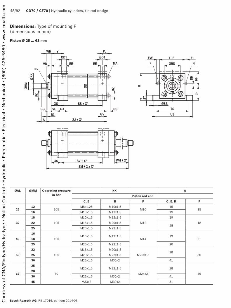
����
��
��
�� �
���
���
����
���� �
��
����� �
���
��
��
�� ��
��
�
��
��
��
��
����
���
����� � ���
���
��
�
��
��������� �
����� � � ����� �
����
48/92 CD70 / CF70 | Hydraulic cylinders, tie rod design
Bosch Rexroth AG, RE 17016, edition: 2014-03
Dimensions: Type of mounting F (dimensions in mm)
Piston Ø 25 ... 63 mm
ØAL ØMM Operating pressure in bar
KK A
Piston rod end
C, E B F C, E, B F
2512
105M8x1.25 M10x1.5
M1015
1516 M10x1.5 M12x1.5 19
32
18
105
M10x1.5 M12x1.5
M12
19
1822 M16x1.5 M20x1.528
25 M20x1.5 M22x1.5
40
16
105M10x1.5 M12x1.5
M1419
2118
25 M20x1.5 M22x1.5 28
50
22
105
M16x1.5 M20x1.5
M20x1.528
3025 M20x1.5 M22x1.5
36 M26x1.5 M30x2 41
63
25
70
M20x1.5 M22x1.5
M24x2
28
3628
36 M26x1.5 M30x2 41
45 M33x2 M39x2 51
Court
esy
of CM
A/F
lodyn
e/H
ydra
dyn
e ▪
Motion C
ontr
ol ▪
Hyd
raulic
▪ P
neu
mat
ic ▪
Ele
ctrica
l ▪
Mec
han
ical
▪ (
800)
426-5
480 ▪
ww
w.c
maf
h.c
om

Hydraulic cylinders, tie rod design | CD70 / CG70 49/92
RE 17016, edition: 2014-03, Bosch Rexroth AG
Dimensions: Type of mounting F (dimensions in mm)
ØAL = Piston ØØMM = Piston rod ØX* = Stroke length1) Raised cylinder head and base2) Raised cylinder head except for Ø 32/18 with end position
cushioning "U" or "K"
3) Raised cylinder head for: Ø 40/25; Ø 50/36 and Ø 63/45 with end position cushioning "D" or "S"
4) ØD1 max. 0.5 mm deep5) Adjustable throttle valve for the end position cushioning6) Check valve and bleeding7) Only with piston rod end "E" with double-acting cylinders
ØAL ØMM ØRDf7
NV B3 VE GA GV WH VD ØD ZJ ZM XS SS SV LHh10
RH H DH
2512 25.5 10
5.5 10 38 26 16 6.5 31 114 152 17.5 73 85 19 24 1) 43 +1.3 5
16 28.5 13
32
18 32 14 5.5
10 38 26
16 6
38
115 153
19 70 83 22.5 35.5 2) 46 +1.3 722 34 19
8 25 13 124 17125 38 22
40
16 28.5 135.5
10 38 2616 6
46118 156
19 73 86 25.5 38.5 3) 51 +1.4 818 32 14
25 38 22 8 25 13 127 174
50
2238
198
10 38 2625 13
56127 174
19 73 86 31.7 44.5 3) 64 +1.4 1025 22
36 50 30 10 32 16 134 188
63
25 38 228
10 38 26
25 13
69
130 177
19 76 89 38 51 3) 76 +1.4 15
28 42 24
36 50.7 30 10 32 16 137 191
45 60 41 12 38 19 143 203
ØAL ØMM EE ØD1 4) Y PJ ST ØSB TS US EW max.
E EL max.
BB BZ MA
NmX* 7)
min. Line connection
01 02 01 02
2512
G 1/4 M14x1.5 25 25 33 11 7.5 7 5470 +1.4 12 38 7 6 M5 5.5 25
16
32
18
G 1/4 M14x1.5 25 25 33 11 12 11 6485 +1.5 12 45 7 6 M5 5.5 2522
25
40
16
G 1/4 M14x1.5 25 25 33 11 12 11 7091 +1.5 9 51 4 6 M5 5.5 2518
25
50
22
G 1/4 M14x1.5 25 25 33 11 11 11 82.5104 +1.5 9 63 4 8 M8 23 3025
36
63
25
G 1/4 M14x1.5 25 25 33 11 11 11 95.5116 +1.5 6 76 1 8 M8 23 30
28
36
45
Court
esy
of CM
A/F
lodyn
e/H
ydra
dyn
e ▪
Motion C
ontr
ol ▪
Hyd
raulic
▪ P
neu
mat
ic ▪
Ele
ctrica
l ▪
Mec
han
ical
▪ (
800)
426-5
480 ▪
ww
w.c
maf
h.c
om

����
��
��
�� �
���
���
����
���� �
��
����� �
���
��
��
�� ��
��
�
��
��
��
��
��
���
����� � ���
���
��
�
��
��������� �
����� � � ����� �
����
50/92 CD70 / CF70 | Hydraulic cylinders, tie rod design
Bosch Rexroth AG, RE 17016, edition: 2014-03
Piston Ø 80 ... 200 mm
ØAL ØMM Operating pressure in bar
KK A
Piston rod end
C, E B F C, E, B F
80
36
70
M26x1.5 M30x2
M30x2
41
4545 M33x2 M39x2 51
56 M39x2 M45x2 57
100
45
70
M33x2 M39x2
M39x3
51
6550 M39x2 M45x2 57
70 M48x2 M56x2 76
125
50
70
M39x2 M45x2
M42x3
57
6556
63 M48x2 M56x2 76
90 M64x2 M76x2 89
150
63
50
M48x2 M56x2
M45x3
76
6870
80 M58x2 M68x2 89
100 M76x2 M95x2 101
200
90
40
M64x2 M76x2
M52x3
89
70100 M76x2 M95x2 101
140 M100x2 M130x2 140
Dimensions: Type of mounting F (dimensions in mm)
Court
esy
of CM
A/F
lodyn
e/H
ydra
dyn
e ▪
Motion C
ontr
ol ▪
Hyd
raulic
▪ P
neu
mat
ic ▪
Ele
ctrica
l ▪
Mec
han
ical
▪ (
800)
426-5
480 ▪
ww
w.c
maf
h.c
om

Hydraulic cylinders, tie rod design | CD70 / CG70 51/92
RE 17016, edition: 2014-03, Bosch Rexroth AG
Dimensions: Type of mounting F (dimensions in mm)
ØAL = Piston ØØMM = Piston rod ØX* = Stroke length
4) ØD1 max. 0.5 mm deep5) Adjustable throttle valve for the end position cushioning6) Check valve and bleeding7) Only with piston rod end "E" with double-acting cylinders
ØAL ØMM ØRDf7
NV B3 VE GA GV WH VD ØD ZJ ZM XS SS SV LHh10
H DH
80
36 50 30 10
16 45 33
25 10
86
149 202
28.5 82.5 95 47.595 +1.5 1545 60 41 12 32
13156 216
56 70 46 15 35 159 222
100
45 60 41 12
16 45 33
3213
106
156 216
28.5 82.5 95 57.1114 +1.5 1550 66.6 46
1535 159 222
70 90 60 41 16 165 234
125
50 66.646
15 16 45 33
35 13
135
165 228
33.5 79.5 91 69.8140 +1.6 30
56 70
63 79.3 5541 16 171 240
90 108 75
150
63 79.3 55
15 19 51 40 38 13 160 184 252 36.5 92 103 82.5165 +1.6 35
70 90 60
80 95.2 75
100 120 85
200
90 108 75
15 19 51 40 38 13 215 187 255 36.5 95 106 108216 +1.8 55100 120 85
140 158 120
ØAL ØMM EE ØD1 4) Y PJ ST ØSB TS US EW max.
E EL max.
BB BZ MA
NmX* 7)
min. Line connection
01 02 01 02
80
36
G 1/2 M22x1.5 34 34 42 14.5 19 14 120.5145 +1.6 12 95 11 10 M10 46 3045
56
100
45
G 1/2 M22x1.5 34 34 42 14.5 19 14 139.5164 +1.6 9 114 8 12 M12 80 4550
70
125
50
G 1/2 M22x1.5 34 34 42 14.5 24 23 174.5210 +1.8 9 140 8 13 M14 125 55
56
63
90
150
63
G 3/4 M26x1.5 42 42 48 18 24 23 200235 +1.8 16 165 12 15 M16 195 75
70
80
100
200
90
G 3/4 M26x1.5 42 42 48 18 24 23 251286 +1.9 14 216 10 15 M16 195 115100
140
Court
esy
of CM
A/F
lodyn
e/H
ydra
dyn
e ▪
Motion C
ontr
ol ▪
Hyd
raulic
▪ P
neu
mat
ic ▪
Ele
ctrica
l ▪
Mec
han
ical
▪ (
800)
426-5
480 ▪
ww
w.c
maf
h.c
om
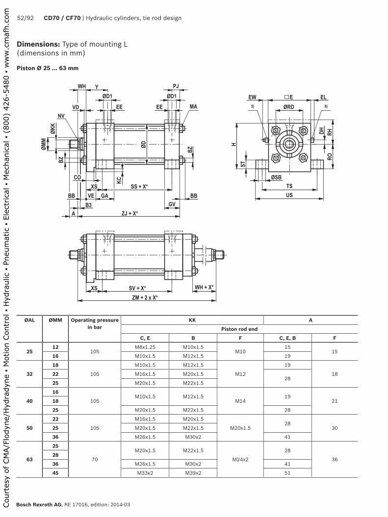
����
��
��
�� �
���
���
����
���� �
��
����� �
���
��
��
�� ��
��
�
��
��
��
��
����
���
����� � � �����
��
�
��
��������� �
����� � � ����� �
����
��
��
52/92 CD70 / CF70 | Hydraulic cylinders, tie rod design
Bosch Rexroth AG, RE 17016, edition: 2014-03
Dimensions: Type of mounting L (dimensions in mm)
Piston Ø 25 ... 63 mm
ØAL ØMM Operating pressure in bar
KK A
Piston rod end
C, E B F C, E, B F
2512
105M8x1.25 M10x1.5
M1015
1516 M10x1.5 M12x1.5 19
32
18
105
M10x1.5 M12x1.5
M12
19
1822 M16x1.5 M20x1.528
25 M20x1.5 M22x1.5
40
16
105M10x1.5 M12x1.5
M1419
2118
25 M20x1.5 M22x1.5 28
50
22
105
M16x1.5 M20x1.5
M20x1.528
3025 M20x1.5 M22x1.5
36 M26x1.5 M30x2 41
63
25
70
M20x1.5 M22x1.5
M24x2
28
3628
36 M26x1.5 M30x2 41
45 M33x2 M39x2 51
Court
esy
of CM
A/F
lodyn
e/H
ydra
dyn
e ▪
Motion C
ontr
ol ▪
Hyd
raulic
▪ P
neu
mat
ic ▪
Ele
ctrica
l ▪
Mec
han
ical
▪ (
800)
426-5
480 ▪
ww
w.c
maf
h.c
om
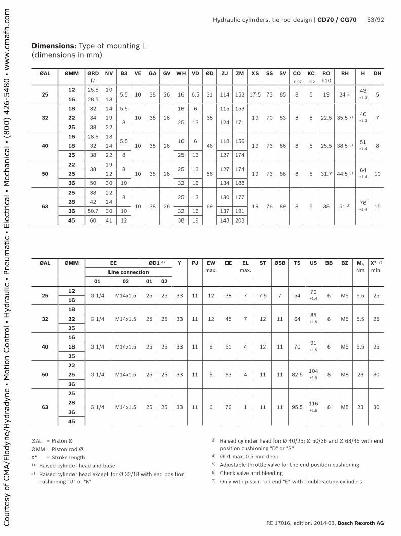
Hydraulic cylinders, tie rod design | CD70 / CG70 53/92
RE 17016, edition: 2014-03, Bosch Rexroth AG
Dimensions: Type of mounting L (dimensions in mm)
ØAL = Piston ØØMM = Piston rod ØX* = Stroke length1) Raised cylinder head and base 2) Raised cylinder head except for Ø 32/18 with end position
cushioning "U" or "K"
3) Raised cylinder head for: Ø 40/25; Ø 50/36 and Ø 63/45 with end position cushioning "D" or "S"
4) ØD1 max. 0.5 mm deep 5) Adjustable throttle valve for the end position cushioning6) Check valve and bleeding7) Only with piston rod end "E" with double-acting cylinders
ØAL ØMM ØRDf7
NV B3 VE GA GV WH VD ØD ZJ ZM XS SS SV CO‒0.07
KC‒0.2
ROh10
RH H DH
2512 25.5 10
5.5 10 38 26 16 6.5 31 114 152 17.5 73 85 8 5 19 24 1) 43 +1.3 5
16 28.5 13
32
18 32 14 5.5
10 38 26
16 6
38
115 153
19 70 83 8 5 22.5 35.5 2) 46 +1.3 722 34 19
8 25 13 124 17125 38 22
40
16 28.5 135.5
10 38 2616 6
46118 156
19 73 86 8 5 25.5 38.5 3) 51 +1.4 818 32 14
25 38 22 8 25 13 127 174
50
2238
198
10 38 2625 13
56127 174
19 73 86 8 5 31.7 44.5 3) 64 +1.4 1025 22
36 50 30 10 32 16 134 188
63
25 38 228
10 38 26
25 13
69
130 177
19 76 89 8 5 38 51 3) 76 +1.4 15
28 42 24
36 50.7 30 10 32 16 137 191
45 60 41 12 38 19 143 203
ØAL ØMM EE ØD1 4) Y PJ EW max.
E EL max.
ST ØSB TS US BB BZ MA
NmX* 7)
min. Line connection
01 02 01 02
2512
G 1/4 M14x1.5 25 25 33 11 12 38 7 7.5 7 5470 +1.4 6 M5 5.5 25
16
32
18
G 1/4 M14x1.5 25 25 33 11 12 45 7 12 11 6485 +1.5 6 M5 5.5 2522
25
40
16
G 1/4 M14x1.5 25 25 33 11 9 51 4 12 11 7091 +1.5 6 M5 5.5 2518
25
50
22
G 1/4 M14x1.5 25 25 33 11 9 63 4 11 11 82.5104 +1.5 8 M8 23 3025
36
63
25
G 1/4 M14x1.5 25 25 33 11 6 76 1 11 11 95.5116 +1.5 8 M8 23 30
28
36
45
Court
esy
of CM
A/F
lodyn
e/H
ydra
dyn
e ▪
Motion C
ontr
ol ▪
Hyd
raulic
▪ P
neu
mat
ic ▪
Ele
ctrica
l ▪
Mec
han
ical
▪ (
800)
426-5
480 ▪
ww
w.c
maf
h.c
om

����
��
��
�� �
���
���
����
���� �
��
����� �
���
��
��
�� ��
��
�
��
��
��
��
��
���
����� � � �����
��
�
��
��������� �
����� � � ����� �
����
��
��
54/92 CD70 / CF70 | Hydraulic cylinders, tie rod design
Bosch Rexroth AG, RE 17016, edition: 2014-03
Piston Ø 80 ... 200 mm
ØAL ØMM Operating pressure in bar
KK A
Piston rod end
C, E B F C, E, B F
80
36
70
M26x1.5 M30x2
M30x2
41
4545 M33x2 M39x2 51
56 M39x2 M45x2 57
100
45
70
M33x2 M39x2
M39x3
51
6550 M39x2 M45x2 57
70 M48x2 M56x2 76
125
50
70
M39x2 M45x2
M42x3
57
6556
63 M48x2 M56x2 76
90 M64x2 M76x2 89
150
63
50
M48x2 M56x2
M45x3
76
6870
80 M58x2 M68x2 89
100 M76x2 M95x2 101
200
90
‒ ‒ ‒ ‒ ‒ ‒100
140
Dimensions: Type of mounting L (dimensions in mm)
Court
esy
of CM
A/F
lodyn
e/H
ydra
dyn
e ▪
Motion C
ontr
ol ▪
Hyd
raulic
▪ P
neu
mat
ic ▪
Ele
ctrica
l ▪
Mec
han
ical
▪ (
800)
426-5
480 ▪
ww
w.c
maf
h.c
om

Hydraulic cylinders, tie rod design | CD70 / CG70 55/92
RE 17016, edition: 2014-03, Bosch Rexroth AG
Dimensions: Type of mounting L (dimensions in mm)
ØAL = Piston ØØMM = Piston rod ØX* = Stroke length
4) ØD1 max. 0.5 mm deep5) Adjustable throttle valve for the end position cushioning6) Check valve and bleeding 7) Only with piston rod end "E" with double-acting cylinders
ØAL ØMM ØRDf7
NV B3 VE GA GV WH VD ØD ZJ ZM XS SS SV CO‒0.07
KC‒0.2
ROh10
H DH
80
36 50 30 10
16 45 33
25 10
86
149 202
28.5 82.5 95 14 8 47.595 +1.5 1545 60 41 12 32
13156 216
56 70 46 15 35 159 222
100
45 60 41 12
16 45 33
3213
106
156 216
28.5 82.5 95 14 8 57.1114 +1.5 1550 66.6 46
1535 159 222
70 90 60 41 16 165 234
125
50 66.646
15 16 45 33
35 13
135
165 228
33.5 79.5 91 14 8 69.8140 +1.6 30
56 70
63 79.3 5541 16 171 240
90 108 75
150
63 79.3 55
15 19 51 40 38 13 160 184 252 36.5 92 103 18 9.5 82.5165 +1.6 35
70 90 60
80 95.2 75
100 120 85
200
90
‒ ‒ ‒ ‒ ‒ ‒ ‒ ‒ ‒ ‒ ‒ ‒ ‒ ‒ ‒ ‒ ‒ ‒ ‒100
140
ØAL ØMM EE ØD1 4) Y PJ EW max.
E EL max.
ST ØSB TS US BB BZ MA
NmX* 7)
min. Line connection
01 02 01 02
80
36
G 1/2 M22x1.5 34 34 42 14.5 12 95 11 19 14 120.5145 +1.6 10 M10 46 3045
56
100
45
G 1/2 M22x1.5 34 34 42 14.5 9 114 8 19 14 139.5164 +1.6 12 M12 80 4550
70
125
50
G 1/2 M22x1.5 34 34 42 14.5 9 140 8 24 23 174.5210 +1.8 13 M14 125 55
56
63
90
150
63
G 3/4 M26x1.5 42 42 48 18 16 165 12 24 23 200235 +1.8 15 M16 195 75
70
80
100
200
90
‒ ‒ ‒ ‒ ‒ ‒ ‒ ‒ ‒ ‒ ‒ ‒ ‒ ‒ ‒ ‒ ‒100
140
Court
esy
of CM
A/F
lodyn
e/H
ydra
dyn
e ▪
Motion C
ontr
ol ▪
Hyd
raulic
▪ P
neu
mat
ic ▪
Ele
ctrica
l ▪
Mec
han
ical
▪ (
800)
426-5
480 ▪
ww
w.c
maf
h.c
om

��
��
��
��
��
���
���
�� ��
���� �
��
������
���
��
��
���� ��
�
���
�
���
��
�
�
����������
������
������
������ ��
������ ��
���
���
������ ��
����
56/92 CD70 / CF70 | Hydraulic cylinders, tie rod design
Bosch Rexroth AG, RE 17016, edition: 2014-03
Dimensions: Type of mounting M (dimensions in mm)
Piston Ø 25 ... 63 mm
ØAL ØMM Operating pressure in bar
KK A
Piston rod end
C, E B F C, E, B F
2512
105M8x1.25 M10x1.5
M1015
1516 M10x1.5 M12x1.5 19
32
18
105
M10x1.5 M12x1.5
M12
19
1822 M16x1.5 M20x1.528
25 M20x1.5 M22x1.5
40
16
105M10x1.5 M12x1.5
M1419
2118
25 M20x1.5 M22x1.5 28
50
22
105
M16x1.5 M20x1.5
M20x1.528
3025 M20x1.5 M22x1.5
36 M26x1.5 M30x2 41
63
25
70
M20x1.5 M22x1.5
M24x2
28
3628
36 M26x1.5 M30x2 41
45 M33x2 M39x2 51
2 seal rings
Court
esy
of CM
A/F
lodyn
e/H
ydra
dyn
e ▪
Motion C
ontr
ol ▪
Hyd
raulic
▪ P
neu
mat
ic ▪
Ele
ctrica
l ▪
Mec
han
ical
▪ (
800)
426-5
480 ▪
ww
w.c
maf
h.c
om

Hydraulic cylinders, tie rod design | CD70 / CG70 57/92
RE 17016, edition: 2014-03, Bosch Rexroth AG
Dimensions: Type of mounting M (dimensions in mm)
ØAL = Piston ØØMM = Piston rod ØX* = Stroke length
1) Only with piston rod end "E" with double-acting cylinders5) Adjustable throttle valve for the end position cushioning6) Check valve and bleeding
ØAL ØMM ØRDf7
NV B3 VE GA GV WH VD ØD ZJ ZM XS SS SV PX PY ROh10
2512 25.5 10
5.5 10 38 26 16 6.5 31 114 152 17.5 73 85 33 54 1916 28.5 13
32
18 32 14 5.5
10 38 26
16 6
38
115 153
19 70 83 33.5 54 22.522 34 198 25 13 124 171
25 38 22
40
16 28.5 135.5
10 38 2616 6
46118 156
19 73 86 35 54 25.518 32 14
25 38 22 8 25 13 127 174
50
2238
198
10 38 2625 13
56127 174
19 73 86 35 54 31.725 22
36 50 30 10 32 16 134 188
63
25 38 228
10 38 26
25 13
69
130 177
19 76 89 35 57 3828 42 24
36 50.7 30 10 32 16 137 191
45 60 41 12 38 19 143 203
ØAL ØMM ST ØSB TS US EW max.
E EL max.
ØMF ØMD Seal rings 2x
DH H BB BZ MANm
X* 1) min.
2512
7.5 7 5470 +1.4 12 38 7 10 17 13 x 2 5
43 +1.3 6 M5 5.5 25
16
32
18
12 11 6485 +1.5 12 45 7 10 17 13 x 2 7
46 +1.3 6 M5 5.5 2522
25
40
16
12 11 7091 +1.5 9 51 4 12 20 16 x 2 8
51 +1.4 6 M5 5.5 2518
25
50
22
11 11 82.5104 +1.5 9 63 4 12 20 16 x 2 10
64 +1.4 8 M8 23 3025
36
63
25
11 11 95.5116 +1.5 6 76 1 12 20 16 x 2 15
76 +1.4 8 M8 23 30
28
36
45
Court
esy
of CM
A/F
lodyn
e/H
ydra
dyn
e ▪
Motion C
ontr
ol ▪
Hyd
raulic
▪ P
neu
mat
ic ▪
Ele
ctrica
l ▪
Mec
han
ical
▪ (
800)
426-5
480 ▪
ww
w.c
maf
h.c
om

��
��
��
��
��
���
���
�� ��
���� �
��
������
���
��
��
���� ��
�
���
�
���
��
�
�
����������
������
������
������ ��
������ ��
���
���
������ ��
����
58/92 CD70 / CF70 | Hydraulic cylinders, tie rod design
Bosch Rexroth AG, RE 17016, edition: 2014-03
Piston Ø 80 ... 200 mm
ØAL ØMM Operating pressure in bar
KK A
Piston rod end
C, E B F C, E, B F
80
36
70
M26x1.5 M30x2
M30x2
41
4545 M33x2 M39x2 51
56 M39x2 M45x2 57
100
45
70
M33x2 M39x2
M39x3
51
6550 M39x2 M45x2 57
70 M48x2 M56x2 76
125
50
70
M39x2 M45x2
M42x3
57
6556
63 M48x2 M56x2 76
90 M64x2 M76x2 89
150
63
50
M48x2 M56x2
M45x3
76
6870
80 M58x2 M68x2 89
100 M76x2 M95x2 101
200
90
40
M64x2 M76x2
M52x3
89
70100 M76x2 M95x2 101
140 M100x2 M130x2 140
Dimensions: Type of mounting M (dimensions in mm)
2 seal rings
Court
esy
of CM
A/F
lodyn
e/H
ydra
dyn
e ▪
Motion C
ontr
ol ▪
Hyd
raulic
▪ P
neu
mat
ic ▪
Ele
ctrica
l ▪
Mec
han
ical
▪ (
800)
426-5
480 ▪
ww
w.c
maf
h.c
om

Hydraulic cylinders, tie rod design | CD70 / CG70 59/92
RE 17016, edition: 2014-03, Bosch Rexroth AG
Dimensions: Type of mounting M (dimensions in mm)
ØAL = Piston ØØMM = Piston rod ØX* = Stroke length
1) Only with piston rod end "E" with double-acting cylinders5) Adjustable throttle valve for the end position cushioning6) Check valve and bleeding
ØAL ØMM ØRDf7
NV B3 VE GA GV WH VD ØD ZJ ZM XS SS SV PX PY ROh10
80
36 50 30 10
16 45 33
25 10
86
149 202
28.5 82.5 95 42.5 67 47.545 60 41 12 3213
156 216
56 70 46 15 35 159 222
100
45 60 41 12
16 45 33
3213
106
156 216
28.5 82.5 95 42.5 67 57.150 66.6 4615
35 159 222
70 90 60 41 16 165 234
125
50 66.646
15 16 45 33
35 13
135
165 228
33.5 79.5 91 42.5 73 69.856 70
63 79.3 5541 16 171 240
90 108 75
150
63 79.3 55
15 19 51 40 38 13 160 184 252 36.5 92 103 48.5 79 82.570 90 60
80 95.2 75
100 120 85
200
90 108 75
15 19 51 40 38 13 215 187 255 36.5 95 106 48.5 82 108100 120 85
140 158 120
ØAL ØMM ST ØSB TS US EW max.
E EL max.
ØMF ØMD Seal rings 2x
DH H BB BZ MANm
X* 1) min.
80
36
19 14 120.5145 +1.6 12 95 11 16 24 19 x 2.5 15
95 +1.5 10 M10 46 3045
56
100
45
19 14 139.5164 +1.6 9 114 8 16 24 19 x 2.5 15
114 +1.5 12 M12 80 4550
70
125
50
24 23 174.5210 +1.8 9 140 8 16 24 19 x 2.5 30
140 +1.6 13 M14 125 55
56
63
90
150
63
24 23 200235 +1.8 16 165 12 22 30 25 x 2.5 35
165 +1.6 15 M16 195 75
70
80
100
200
90
24 23 251286 +1.9 14 216 10 22 30 25 x 2.5 55
216 +1.8 15 M16 195 115100
140
Court
esy
of CM
A/F
lodyn
e/H
ydra
dyn
e ▪
Motion C
ontr
ol ▪
Hyd
raulic
▪ P
neu
mat
ic ▪
Ele
ctrica
l ▪
Mec
han
ical
▪ (
800)
426-5
480 ▪
ww
w.c
maf
h.c
om

����
��
��
�� �
���
��
��� ��
���� �
��
����� �
���
��
��
�� ��
��
�
��
��
��
��
����
���
����� � �
��
��
��������� �
����� � � ����� �
�� ��
����
60/92 CD70 / CF70 | Hydraulic cylinders, tie rod design
Bosch Rexroth AG, RE 17016, edition: 2014-03
Dimensions: Type of mounting N (dimensions in mm)
Piston Ø 25 ... 63 mm
ØAL ØMM Operating pressure in bar
KK A
Piston rod end
C, E B F C, E, B F
2512
105M8x1.25 M10x1.5
M1015
1516 M10x1.5 M12x1.5 19
32
18
105
M10x1.5 M12x1.5
M12
19
1822 M16x1.5 M20x1.528
25 M20x1.5 M22x1.5
40
16
105M10x1.5 M12x1.5
M1419
2118
25 M20x1.5 M22x1.5 28
50
22
105
M16x1.5 M20x1.5
M20x1.528
3025 M20x1.5 M22x1.5
36 M26x1.5 M30x2 41
63
25
70
M20x1.5 M22x1.5
M24x2
28
3628
36 M26x1.5 M30x2 41
45 M33x2 M39x2 51
Court
esy
of CM
A/F
lodyn
e/H
ydra
dyn
e ▪
Motion C
ontr
ol ▪
Hyd
raulic
▪ P
neu
mat
ic ▪
Ele
ctrica
l ▪
Mec
han
ical
▪ (
800)
426-5
480 ▪
ww
w.c
maf
h.c
om

Hydraulic cylinders, tie rod design | CD70 / CG70 61/92
RE 17016, edition: 2014-03, Bosch Rexroth AG
Dimensions: Type of mounting N (dimensions in mm)
ØAL = Piston ØØMM = Piston rod ØX* = Stroke length1) Raised cylinder head and base 2) Raised cylinder head except for Ø 32/18 with end position
cushioning "U" or "K"
3) Raised cylinder head for: Ø 40/25; Ø 50/36 and Ø 63/45 with end position cushioning "D" or "S"
4) ØD1 max. 0.5 mm deep5) Adjustable throttle valve for the end position cushioning6) Check valve and bleeding7) Only with piston rod end "E" with double-acting cylinders
ØAL ØMM ØRDf7
NV B3 VE GA GV WH VD ØD ZJ ZM XS SS ROh10
RH DH
2512 25.5 10
5.5 10 38 26 16 6.5 31 114 152 33 54 19 24 1) 516 28.5 13
32
18 32 14 5.5
10 38 26
16 6
38
115 153
33.5 54 22.5 35.5 2) 722 34 198 25 13 124 171
25 38 22
40
16 28.5 135.5
10 38 2616 6
46118 156
33.5 57 25.5 38.5 3) 818 32 14
25 38 22 8 25 13 127 174
50
2238
198
10 38 2625 13
56127 174
33.5 57 31.5 44.5 3) 1025 22
36 50 30 10 32 16 134 188
63
25 38 228
10 38 26
25 13
69
130 177
33.5 60.5 38 51 3) 1528 42 24
36 50.7 30 10 32 16 137 191
45 60 41 12 38 19 143 203
ØAL ØMM EE ØD1 4) EWmax.
E ELmax.
Y PJ MG B2 BG BB BZ MA
NmX* 7) min.Line connection
01 02 01 02
2512
G 1/4 M14x1.5 25 25 12 38 7 33 11 M5 6 13.5 6 M5 5.5 2516
32
18
G 1/4 M14x1.5 25 25 12 45 7 33 11 M6
9
14.5 6 M5 5.5 25227
25
40
16
G 1/4 M14x1.5 25 25 9 51 4 33 11 M6
9
15.5 6 M5 5.5 25186
25
50
22
G 1/4 M14x1.5 25 25 9 63 4 33 11 M812
22 8 M8 23 3025
36 8
63
25
G 1/4 M14x1.5 25 25 6 76 1 33 11 M10
15
31 8 M8 23 3028 16
369
45
Court
esy
of CM
A/F
lodyn
e/H
ydra
dyn
e ▪
Motion C
ontr
ol ▪
Hyd
raulic
▪ P
neu
mat
ic ▪
Ele
ctrica
l ▪
Mec
han
ical
▪ (
800)
426-5
480 ▪
ww
w.c
maf
h.c
om
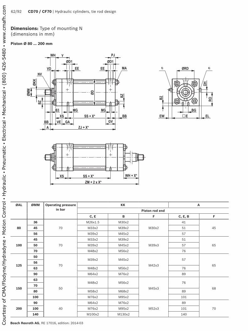
����
��
��
�� �
���
��
��� ��
���� �
��
����� �
���
��
��
�� ��
��
�
��
��
��
��
��
���
����� � �
��
��
��������� �
����� � � ����� �
�� ��
����
62/92 CD70 / CF70 | Hydraulic cylinders, tie rod design
Bosch Rexroth AG, RE 17016, edition: 2014-03
ØAL ØMM Operating pressure in bar
KK A
Piston rod end
C, E B F C, E, B F
80
36
70
M26x1.5 M30x2
M30x2
41
4545 M33x2 M39x2 51
56 M39x2 M45x2 57
100
45
70
M33x2 M39x2
M39x3
51
6550 M39x2 M45x2 57
70 M48x2 M56x2 76
125
50
70
M39x2 M45x2
M42x3
57
6556
63 M48x2 M56x2 76
90 M64x2 M76x2 89
150
63
50
M48x2 M56x2
M45x3
76
6870
80 M58x2 M68x2 89
100 M76x2 M95x2 101
200
90
40
M64x2 M76x2
M52x3
89
70100 M76x2 M95x2 101
140 M100x2 M130x2 140
Dimensions: Type of mounting N (dimensions in mm)
Piston Ø 80 ... 200 mm
Court
esy
of CM
A/F
lodyn
e/H
ydra
dyn
e ▪
Motion C
ontr
ol ▪
Hyd
raulic
▪ P
neu
mat
ic ▪
Ele
ctrica
l ▪
Mec
han
ical
▪ (
800)
426-5
480 ▪
ww
w.c
maf
h.c
om
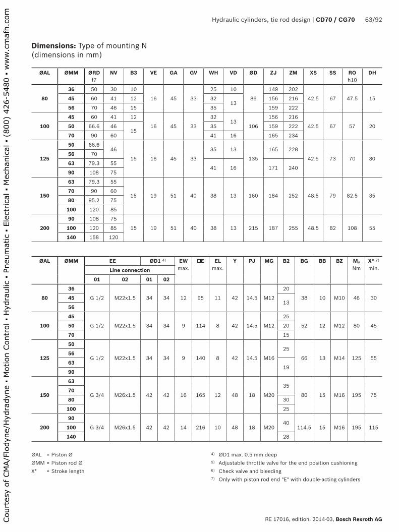
Hydraulic cylinders, tie rod design | CD70 / CG70 63/92
RE 17016, edition: 2014-03, Bosch Rexroth AG
Dimensions: Type of mounting N (dimensions in mm)
ØAL = Piston ØØMM = Piston rod ØX* = Stroke length
4) ØD1 max. 0.5 mm deep5) Adjustable throttle valve for the end position cushioning6) Check valve and bleeding7) Only with piston rod end "E" with double-acting cylinders
ØAL ØMM ØRDf7
NV B3 VE GA GV WH VD ØD ZJ ZM XS SS ROh10
DH
80
36 50 30 10
16 45 33
25 10
86
149 202
42.5 67 47.5 1545 60 41 12 3213
156 216
56 70 46 15 35 159 222
100
45 60 41 12
16 45 33
3213
106
156 216
42.5 67 57 2050 66.6 4615
35 159 222
70 90 60 41 16 165 234
125
50 66.646
15 16 45 33
35 13
135
165 228
42.5 73 70 3056 70
63 79.3 5541 16 171 240
90 108 75
150
63 79.3 55
15 19 51 40 38 13 160 184 252 48.5 79 82.5 3570 90 60
80 95.2 75
100 120 85
200
90 108 75
15 19 51 40 38 13 215 187 255 48.5 82 108 55100 120 85
140 158 120
ØAL ØMM EE ØD1 4) EWmax.
E ELmax.
Y PJ MG B2 BG BB BZ MA
NmX* 7) min.Line connection
01 02 01 02
80
36
G 1/2 M22x1.5 34 34 12 95 11 42 14.5 M12
20
38 10 M10 46 304513
56
100
45
G 1/2 M22x1.5 34 34 9 114 8 42 14.5 M12
25
52 12 M12 80 4550 20
70 15
125
50
G 1/2 M22x1.5 34 34 9 140 8 42 14.5 M16
25
66 13 M14 125 5556
6319
90
150
63
G 3/4 M26x1.5 42 42 16 165 12 48 18 M20
35
80 15 M16 195 7570
80 30
100 25
200
90
G 3/4 M26x1.5 42 42 14 216 10 48 18 M2040
114.5 15 M16 195 115100
140 28
Court
esy
of CM
A/F
lodyn
e/H
ydra
dyn
e ▪
Motion C
ontr
ol ▪
Hyd
raulic
▪ P
neu
mat
ic ▪
Ele
ctrica
l ▪
Mec
han
ical
▪ (
800)
426-5
480 ▪
ww
w.c
maf
h.c
om
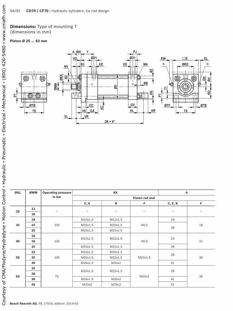
��
��
��
��
�� �
���
��
�
��
��
���� �
��
������
���
��
��
��
��
���
��
���
��
��
����
���
��
��
��
��
��
��
�� ��
�
��
�
��� ��� ���
����
64/92 CD70 / CF70 | Hydraulic cylinders, tie rod design
Bosch Rexroth AG, RE 17016, edition: 2014-03
Dimensions: Type of mounting T (dimensions in mm)
Piston Ø 25 ... 63 mm
ØAL ØMM Operating pressure in bar
KK A
Piston rod end
C, E B F C, E, B F
2512
‒ ‒ ‒ ‒ ‒ ‒16
32
18
105
M10x1.5 M12x1.5
M12
19
1822 M16x1.5 M20x1.528
25 M20x1.5 M22x1.5
40
16
105M10x1.5 M12x1.5
M1419
2118
25 M20x1.5 M22x1.5 28
50
22
105
M16x1.5 M20x1.5
M20x1.528
3025 M20x1.5 M22x1.5
36 M26x1.5 M30x2 41
63
25
70
M20x1.5 M22x1.5
M24x2
28
3628
36 M26x1.5 M30x2 41
45 M33x2 M39x2 51
Court
esy
of CM
A/F
lodyn
e/H
ydra
dyn
e ▪
Motion C
ontr
ol ▪
Hyd
raulic
▪ P
neu
mat
ic ▪
Ele
ctrica
l ▪
Mec
han
ical
▪ (
800)
426-5
480 ▪
ww
w.c
maf
h.c
om

Hydraulic cylinders, tie rod design | CD70 / CG70 65/92
RE 17016, edition: 2014-03, Bosch Rexroth AG
Dimensions: Type of mounting T (dimensions in mm)
ØAL = Piston ØØMM = Piston rod ØX* = Stroke length1) Raised cylinder head except for Ø 32/18 with end position
cushioning "U" or "K"
2) Raised cylinder head for: Ø 40/25; Ø 50/36 and Ø 63/45 with end position cushioning "D" or "S"
3) ØD1 max. 0.5 mm deep 5) Adjustable throttle valve for the end position cushioning6) Check valve and bleeding
ØAL ØMM ØRDf7
NV B3 VE GA GV WH VD ØD ZK RO‒0.2
RH DH EW max.
E EL max.
VL VR CO‒0.07
KC‒0.2
2512
‒ ‒ ‒ ‒ ‒ ‒ ‒ ‒ ‒ ‒ ‒ ‒ ‒ ‒ ‒ ‒ ‒ ‒ ‒ ‒16
32
18 32 14 5.5
10 38 26
16 6
38 137 22.5 35.5 1) 7 12 45 7 7 19 8 522 34 198 25 13
25 38 22
40
16 28.5 135.5
10 38 2616 6
46 140 25.5 38.5 2) 8 9 51 4 6.5 19.5 8 518 32 14
25 38 22 8 25 13
50
2238
198
10 38 2625 13
56 149 31.7 44.5 2) 10 9 63 4 7.5 23.5 8 525 22
36 50 30 10 32 16
63
25 38 228
10 38 26
25 13
69 159 38 51 2) 15 6 76 1 8 27 8 528 42 24
36 50.7 30 10 32 16
45 60 41 12 38 19
ØAL ØMM EE ØD1 3) Y PJ HL HR KN‒0.4
PT TS T1 ØTF ØTB BB BZ MA
NmLine connection
01 02 01 02
2512
‒ ‒ ‒ ‒ ‒ ‒ ‒ ‒ ‒ ‒ ‒ ‒ ‒ ‒ ‒ ‒ ‒16
32
18
G 1/4 M14x1.5 25 25 33 11 19 7 0.2 11 33 2 11 6.6 6 M5 5.522
25
40
16
G 1/4 M14x1.5 25 25 33 11 18.5 7.5 0.2 14 36.5 5 14 9 6 M5 5.518
25
50
22
G 1/4 M14x1.5 25 25 33 11 23.5 7.5 0.2 19 46.5 5 14 9.5 8 M8 2325
36
63
25
G 1/4 M14x1.5 25 25 33 11 27 8 0.2 22 55.5 4.5 14 9.5 8 M8 2328
36
45
Court
esy
of CM
A/F
lodyn
e/H
ydra
dyn
e ▪
Motion C
ontr
ol ▪
Hyd
raulic
▪ P
neu
mat
ic ▪
Ele
ctrica
l ▪
Mec
han
ical
▪ (
800)
426-5
480 ▪
ww
w.c
maf
h.c
om
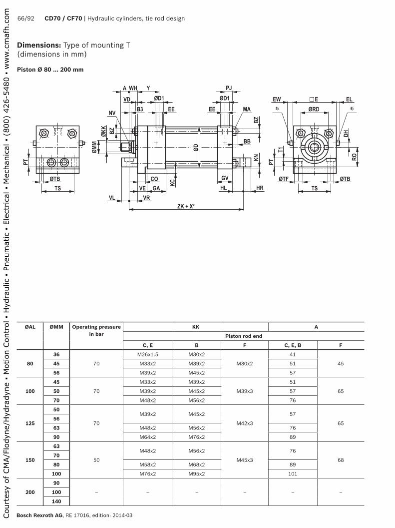
��
��
��
��
�� �
���
��
�
��
��
���� �
��
������
���
��
��
��
��
���
��
���
��
��
��
���
��
��
��
��
��
��
�� ��
�
��
�
��� ��� ���
����
66/92 CD70 / CF70 | Hydraulic cylinders, tie rod design
Bosch Rexroth AG, RE 17016, edition: 2014-03
Piston Ø 80 ... 200 mm
ØAL ØMM Operating pressure in bar
KK A
Piston rod end
C, E B F C, E, B F
80
36
70
M26x1.5 M30x2
M30x2
41
4545 M33x2 M39x2 51
56 M39x2 M45x2 57
100
45
70
M33x2 M39x2
M39x3
51
6550 M39x2 M45x2 57
70 M48x2 M56x2 76
125
50
70
M39x2 M45x2
M42x3
57
6556
63 M48x2 M56x2 76
90 M64x2 M76x2 89
150
63
50
M48x2 M56x2
M45x3
76
6870
80 M58x2 M68x2 89
100 M76x2 M95x2 101
200
90
‒ ‒ ‒ ‒ ‒ ‒100
140
Dimensions: Type of mounting T (dimensions in mm)
Court
esy
of CM
A/F
lodyn
e/H
ydra
dyn
e ▪
Motion C
ontr
ol ▪
Hyd
raulic
▪ P
neu
mat
ic ▪
Ele
ctrica
l ▪
Mec
han
ical
▪ (
800)
426-5
480 ▪
ww
w.c
maf
h.c
om

Hydraulic cylinders, tie rod design | CD70 / CG70 67/92
RE 17016, edition: 2014-03, Bosch Rexroth AG
Dimensions: Type of mounting T (dimensions in mm)
ØAL = Piston ØØMM = Piston rod ØX* = Stroke length
3) ØD1 max. 0.5 mm deep5) Adjustable throttle valve for the end position cushioning6) Check valve and bleeding
ØAL ØMM ØRDf7
NV B3 VE GA GV WH VD ØD ZK RO‒0.2
DH EW max.
E EL max.
VL VR CO‒0.07
KC‒0.2
80
36 50 30 10
16 45 33
25 10
86 168 47.5 15 12 95 11 10 22 14 845 60 41 12 3213
56 70 46 15 35
100
45 60 41 12
16 45 33
3213
106 174.5 57.1 20 9 114 8 11 26 14 850 66.6 4615
35
70 90 60 41 16
125
50 66.646
15 16 45 33
35 13
135 184 69.8 30 9 140 8 13 27 14 856 70
63 79.3 5541 16
90 108 75
150
63 79.3 55
15 19 51 40 38 13 160 197 82.5 35 16 165 12 14.5 25.5 18 9.570 90 60
80 95.2 75
100 120 85
200
90
‒ ‒ ‒ ‒ ‒ ‒ ‒ ‒ ‒ ‒ ‒ ‒ ‒ ‒ ‒ ‒ ‒ ‒ ‒100
140
ØAL ØMM EE ØD1 3) Y PJ HL HR KN‒0.4
PT TS T1 ØTF ØTB BB BZ MA
NmLine connection
01 02 01 02
80
36
G 1/2 M22x1.5 34 34 42 14.5 22 10 0.2 25 70 5 18 11 10 M10 4645
56
100
45
G 1/2 M22x1.5 34 34 42 14.5 24.5 12.5 0.2 32 84.5 5 18 11 12 M12 8050
70
125
50
G 1/2 M22x1.5 34 34 42 14.5 27 13 0.2 38 104 6 20 14 13 M14 12556
63
90
150
63
G 3/4 M26x1.5 42 42 48 18 25.5 14.5 0.2 40 124 ‒ ‒ 14 15 M16 19570
80
100
200
90
‒ ‒ ‒ ‒ ‒ ‒ ‒ ‒ ‒ ‒ ‒ ‒ ‒ ‒ ‒ ‒ ‒100
140
Court
esy
of CM
A/F
lodyn
e/H
ydra
dyn
e ▪
Motion C
ontr
ol ▪
Hyd
raulic
▪ P
neu
mat
ic ▪
Ele
ctrica
l ▪
Mec
han
ical
▪ (
800)
426-5
480 ▪
ww
w.c
maf
h.c
om

��
��
��
��
�� �
���
���
��
������ �
��
����� �
���
��
��
�� ��
��
�
��
��
��
��
����
���
���
��������� �
����� �
����
68/92 CD70 / CF70 | Hydraulic cylinders, tie rod design
Bosch Rexroth AG, RE 17016, edition: 2014-03
Dimensions: Type of mounting P (dimensions in mm)
Piston Ø 25 ... 63 mm
ØAL ØMM Operating pressure in bar
KK A
Piston rod end
C, E B F C, E, B F
2512
105M8x1.25 M10x1.5
M1015
1516 M10x1.5 M12x1.5 19
32
18
105
M10x1.5 M12x1.5
M12
19
1822 M16x1.5 M20x1.528
25 M20x1.5 M22x1.5
40
16
105M10x1.5 M12x1.5
M1419
2118
25 M20x1.5 M22x1.5 28
50
22
105
M16x1.5 M20x1.5
M20x1.528
3025 M20x1.5 M22x1.5
36 M26x1.5 M30x2 41
63
25
70
M20x1.5 M22x1.5
M24x2
28
3628
36 M26x1.5 M30x2 41
45 M33x2 M39x2 51
Court
esy
of CM
A/F
lodyn
e/H
ydra
dyn
e ▪
Motion C
ontr
ol ▪
Hyd
raulic
▪ P
neu
mat
ic ▪
Ele
ctrica
l ▪
Mec
han
ical
▪ (
800)
426-5
480 ▪
ww
w.c
maf
h.c
om
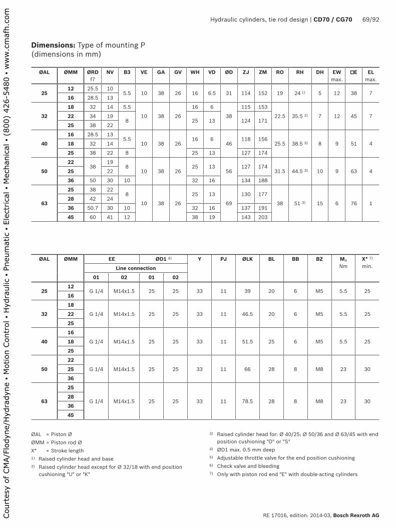
Hydraulic cylinders, tie rod design | CD70 / CG70 69/92
RE 17016, edition: 2014-03, Bosch Rexroth AG
Dimensions: Type of mounting P (dimensions in mm)
ØAL = Piston ØØMM = Piston rod ØX* = Stroke length1) Raised cylinder head and base 2) Raised cylinder head except for Ø 32/18 with end position
cushioning "U" or "K"
3) Raised cylinder head for: Ø 40/25; Ø 50/36 and Ø 63/45 with end position cushioning "D" or "S"
4) ØD1 max. 0.5 mm deep5) Adjustable throttle valve for the end position cushioning6) Check valve and bleeding7) Only with piston rod end "E" with double-acting cylinders
ØAL ØMM ØRDf7
NV B3 VE GA GV WH VD ØD ZJ ZM RO RH DH EW max.
E EL max.
2512 25.5 10
5.5 10 38 26 16 6.5 31 114 152 19 24 1) 5 12 38 716 28.5 13
32
18 32 14 5.5
10 38 26
16 6
38
115 153
22.5 35.5 2) 7 12 45 722 34 198 25 13 124 171
25 38 22
40
16 28.5 135.5
10 38 2616 6
46118 156
25.5 38.5 3) 8 9 51 418 32 14
25 38 22 8 25 13 127 174
50
2238
198
10 38 2625 13
56127 174
31.5 44.5 3) 10 9 63 425 22
36 50 30 10 32 16 134 188
63
25 38 228
10 38 26
25 13
69
130 177
38 51 3) 15 6 76 128 42 24
36 50.7 30 10 32 16 137 191
45 60 41 12 38 19 143 203
ØAL ØMM EE ØD1 4) Y PJ ØLK BL BB BZ MA
NmX* 7) min.Line connection
01 02 01 02
2512
G 1/4 M14x1.5 25 25 33 11 39 20 6 M5 5.5 2516
32
18
G 1/4 M14x1.5 25 25 33 11 46.5 20 6 M5 5.5 2522
25
40
16
G 1/4 M14x1.5 25 25 33 11 51.5 25 6 M5 5.5 2518
25
50
22
G 1/4 M14x1.5 25 25 33 11 66 28 8 M8 23 3025
36
63
25
G 1/4 M14x1.5 25 25 33 11 78.5 28 8 M8 23 3028
36
45
Court
esy
of CM
A/F
lodyn
e/H
ydra
dyn
e ▪
Motion C
ontr
ol ▪
Hyd
raulic
▪ P
neu
mat
ic ▪
Ele
ctrica
l ▪
Mec
han
ical
▪ (
800)
426-5
480 ▪
ww
w.c
maf
h.c
om
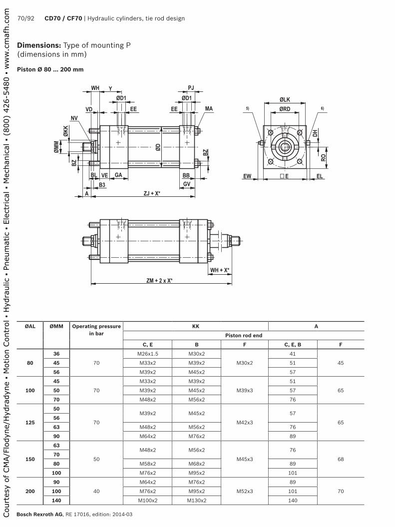
��
��
��
��
�� �
���
���
��
������ �
��
����� �
���
��
��
�� ��
��
�
��
��
��
��
��
���
���
��������� �
����� �
����
70/92 CD70 / CF70 | Hydraulic cylinders, tie rod design
Bosch Rexroth AG, RE 17016, edition: 2014-03
Piston Ø 80 ... 200 mm
ØAL ØMM Operating pressure in bar
KK A
Piston rod end
C, E B F C, E, B F
80
36
70
M26x1.5 M30x2
M30x2
41
4545 M33x2 M39x2 51
56 M39x2 M45x2 57
100
45
70
M33x2 M39x2
M39x3
51
6550 M39x2 M45x2 57
70 M48x2 M56x2 76
125
50
70
M39x2 M45x2
M42x3
57
6556
63 M48x2 M56x2 76
90 M64x2 M76x2 89
150
63
50
M48x2 M56x2
M45x3
76
6870
80 M58x2 M68x2 89
100 M76x2 M95x2 101
200
90
40
M64x2 M76x2
M52x3
89
70100 M76x2 M95x2 101
140 M100x2 M130x2 140
Dimensions: Type of mounting P (dimensions in mm)
Court
esy
of CM
A/F
lodyn
e/H
ydra
dyn
e ▪
Motion C
ontr
ol ▪
Hyd
raulic
▪ P
neu
mat
ic ▪
Ele
ctrica
l ▪
Mec
han
ical
▪ (
800)
426-5
480 ▪
ww
w.c
maf
h.c
om

Hydraulic cylinders, tie rod design | CD70 / CG70 71/92
RE 17016, edition: 2014-03, Bosch Rexroth AG
Dimensions: Type of mounting P (dimensions in mm)
ØAL = Piston ØØMM = Piston rod ØX* = Stroke length
4) ØD1 max. 0.5 mm deep5) Adjustable throttle valve for the end position cushioning6) Check valve and bleeding7) Only with piston rod end "E" with double-acting cylinders
ØAL ØMM ØRDf7
NV B3 VE GA GV WH VD ØD ZJ ZM RO DH EW max.
E EL max.
80
36 50 30 10
16 45 33
25 10
86
149 202
47.5 15 12 95 1145 60 41 12 3213
156 216
56 70 46 15 35 159 222
100
45 60 41 12
16 45 33
3213
106
156 216
57 20 9 114 850 66.6 4615
35 159 222
70 90 60 41 16 165 234
125
50 66.646
15 16 45 33
35 13
135
165 228
70 30 9 140 856 70
63 79.3 5541 16 171 240
90 108 75
150
63 79.3 55
15 19 51 40 38 13 160 184 252 82.5 35 16 165 1270 90 60
80 95.2 75
100 120 85
200
90 108 75
15 19 51 40 38 13 215 187 255 108 55 14 216 10100 120 85
140 158 120
ØAL ØMM EE ØD1 4) Y PJ ØLK BL BB BZ MA
NmX* 7) min.Line connection
01 02 01 02
80
36
G 1/2 M22x1.5 34 34 42 14.5 99 35 10 M10 46 3045
56
100
45
G 1/2 M22x1.5 34 34 42 14.5 119.5 35 12 M12 80 4550
70
125
50
G 1/2 M22x1.5 34 34 42 14.5 150 45 13 M14 125 5556
63
90
150
63
G 3/4 M26x1.5 42 42 48 18 177 45 15 M16 195 7570
80
100
200
90
G 3/4 M26x1.5 42 42 48 18 232 58 15 M16 195 115100
140
Court
esy
of CM
A/F
lodyn
e/H
ydra
dyn
e ▪
Motion C
ontr
ol ▪
Hyd
raulic
▪ P
neu
mat
ic ▪
Ele
ctrica
l ▪
Mec
han
ical
▪ (
800)
426-5
480 ▪
ww
w.c
maf
h.c
om

��
��
��
��
�� �
���
���
��
������ �
��
��� ���
�
��
�� ��
��
��
��
��
��
�
����
���
�������
72/92 CD70 / CF70 | Hydraulic cylinders, tie rod design
Bosch Rexroth AG, RE 17016, edition: 2014-03
Dimensions: Type of mounting Q (dimensions in mm)
Piston Ø 25 ... 63 mm
ØAL ØMM Operating pressure in bar
KK A
Piston rod end
C, E B F C, E, B F
2512
105M8x1.25 M10x1.5
M1015
1516 M10x1.5 M12x1.5 19
32
18
105
M10x1.5 M12x1.5
M12
19
1822 M16x1.5 M20x1.528
25 M20x1.5 M22x1.5
40
16
105M10x1.5 M12x1.5
M1419
2118
25 M20x1.5 M22x1.5 28
50
22
105
M16x1.5 M20x1.5
M20x1.528
3025 M20x1.5 M22x1.5
36 M26x1.5 M30x2 41
63
25
70
M20x1.5 M22x1.5
M24x2
28
3628
36 M26x1.5 M30x2 41
45 M33x2 M39x2 51
Court
esy
of CM
A/F
lodyn
e/H
ydra
dyn
e ▪
Motion C
ontr
ol ▪
Hyd
raulic
▪ P
neu
mat
ic ▪
Ele
ctrica
l ▪
Mec
han
ical
▪ (
800)
426-5
480 ▪
ww
w.c
maf
h.c
om

Hydraulic cylinders, tie rod design | CD70 / CG70 73/92
RE 17016, edition: 2014-03, Bosch Rexroth AG
Dimensions: Type of mounting Q (dimensions in mm)
ØAL = Piston ØØMM = Piston rod ØX* = Stroke length1) Raised cylinder head and base 2) Raised cylinder head except for Ø 32/18 with end position
cushioning "U" or "K"
3) Raised cylinder head for: Ø 40/25; Ø 50/36 and Ø 63/45 with end position cushioning "D" or "S"
4) ØD1 max. 0.5 mm deep5) Adjustable throttle valve for the end position cushioning6) Check valve and bleeding
ØAL ØMM ØRDf7
NV B3 VE GA GV WH VD ØD ZJ RO RH DH EW max.
E EL max.
2512 25.5 10
5.5 10 38 26 16 6.5 31 114 19 24 1) 5 12 38 716 28.5 13
32
18 32 14 5.5
10 38 26
16 6
38
115
22.5 35.5 2) 7 12 45 722 34 198 25 13 124
25 38 22
40
16 28.5 135.5
10 38 2616 6
46118
25.5 38.5 3) 8 9 51 418 32 14
25 38 22 8 25 13 127
50
2238
198
10 38 2625 13
56127
31.5 44.5 3) 10 9 63 425 22
36 50 30 10 32 16 134
63
25 38 228
10 38 26
25 13
69
130
38 51 3) 15 6 76 128 42 24
36 50.7 30 10 32 16 137
45 60 41 12 38 19 143
ØAL ØMM EE ØD1 4) Y PJ ØLK BL BT BZ MA
NmLine connection
01 02 01 02
2512
G 1/4 M14x1.5 25 25 33 11 39 20 4 M5 5.516
32
18
G 1/4 M14x1.5 25 25 33 11 46.5 20 4 M5 5.522
25
40
16
G 1/4 M14x1.5 25 25 33 11 51.5 25 4 M5 5.518
25
50
22
G 1/4 M14x1.5 25 25 33 11 66 28 6.5 M8 2325
36
63
25
G 1/4 M14x1.5 25 25 33 11 78.5 28 6.5 M8 2328
36
45
Court
esy
of CM
A/F
lodyn
e/H
ydra
dyn
e ▪
Motion C
ontr
ol ▪
Hyd
raulic
▪ P
neu
mat
ic ▪
Ele
ctrica
l ▪
Mec
han
ical
▪ (
800)
426-5
480 ▪
ww
w.c
maf
h.c
om
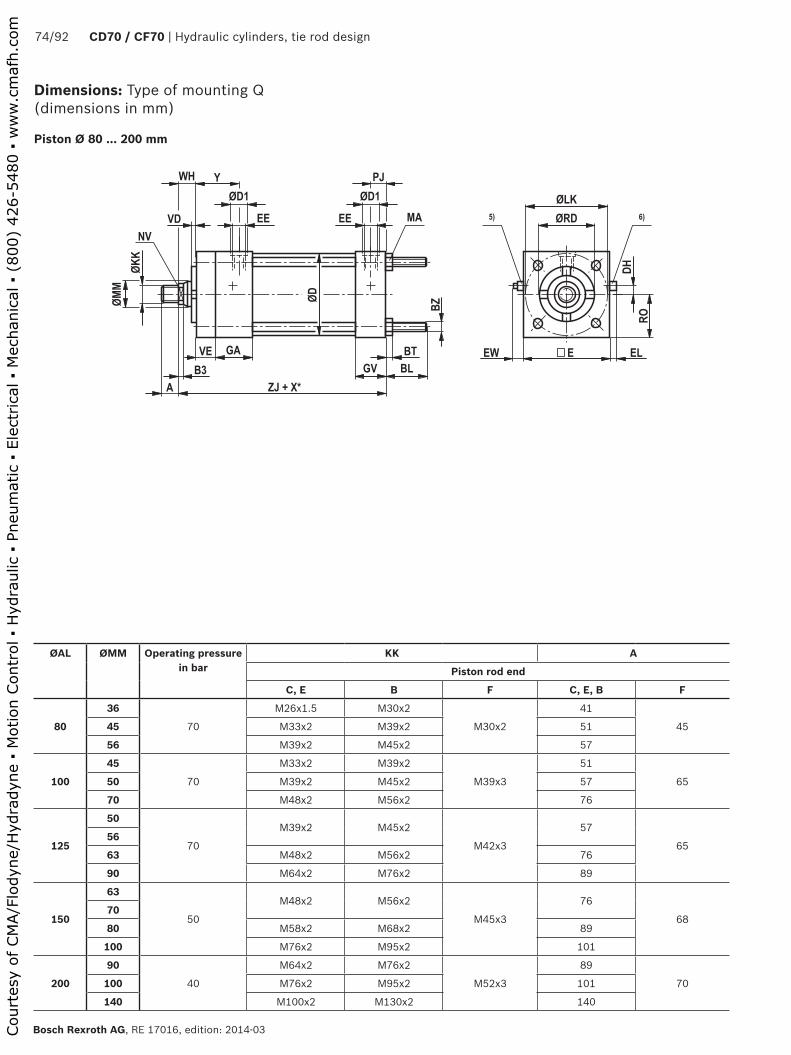
��
��
��
��
�� �
���
���
��
������ �
��
��� ���
�
��
�� ��
��
��
��
��
��
�
��
���
�������
74/92 CD70 / CF70 | Hydraulic cylinders, tie rod design
Bosch Rexroth AG, RE 17016, edition: 2014-03
Piston Ø 80 ... 200 mm
ØAL ØMM Operating pressure in bar
KK A
Piston rod end
C, E B F C, E, B F
80
36
70
M26x1.5 M30x2
M30x2
41
4545 M33x2 M39x2 51
56 M39x2 M45x2 57
100
45
70
M33x2 M39x2
M39x3
51
6550 M39x2 M45x2 57
70 M48x2 M56x2 76
125
50
70
M39x2 M45x2
M42x3
57
6556
63 M48x2 M56x2 76
90 M64x2 M76x2 89
150
63
50
M48x2 M56x2
M45x3
76
6870
80 M58x2 M68x2 89
100 M76x2 M95x2 101
200
90
40
M64x2 M76x2
M52x3
89
70100 M76x2 M95x2 101
140 M100x2 M130x2 140
Dimensions: Type of mounting Q (dimensions in mm)
Court
esy
of CM
A/F
lodyn
e/H
ydra
dyn
e ▪
Motion C
ontr
ol ▪
Hyd
raulic
▪ P
neu
mat
ic ▪
Ele
ctrica
l ▪
Mec
han
ical
▪ (
800)
426-5
480 ▪
ww
w.c
maf
h.c
om

Hydraulic cylinders, tie rod design | CD70 / CG70 75/92
RE 17016, edition: 2014-03, Bosch Rexroth AG
Dimensions: Type of mounting Q (dimensions in mm)
ØAL = Piston ØØMM = Piston rod ØX* = Stroke length
4) ØD1 max. 0.5 mm deep5) Adjustable throttle valve for the end position cushioning6) Check valve and bleeding
ØAL ØMM ØRDf7
NV B3 VE GA GV WH VD ØD ZJ RO DH EW max.
E EL max.
80
36 50 30 10
16 45 33
25 10
86
149
47.5 15 12 95 1145 60 41 12 3213
156
56 70 46 15 35 159
100
45 60 41 12
16 45 33
3213
106
156
57 20 9 114 850 66.6 4615
35 159
70 90 60 41 16 165
125
50 66.646
15 16 45 33
35 13
135
165
70 30 9 140 856 70
63 79.3 5541 16 171
90 108 75
150
63 79.3 55
15 19 51 40 38 13 160 184 82.5 35 16 165 1270 90 60
80 95.2 75
100 120 85
200
90 108 75
15 19 51 40 38 13 215 187 108 55 14 216 10100 120 85
140 158 120
ØAL ØMM EE ØD1 4) Y PJ ØLK BL BT BZ MA
NmLine connection
01 02 01 02
80
36
G 1/2 M22x1.5 34 34 42 14.5 99 35 8 M10 4645
56
100
45
G 1/2 M22x1.5 34 34 42 14.5 119.5 35 10 M12 8050
70
125
50
G 1/2 M22x1.5 34 34 42 14.5 150 45 11 M14 12556
63
90
150
63
G 3/4 M26x1.5 42 42 48 18 177 45 13 M16 19570
80
100
200
90
G 3/4 M26x1.5 42 42 48 18 232 58 13 M16 195100
140
Court
esy
of CM
A/F
lodyn
e/H
ydra
dyn
e ▪
Motion C
ontr
ol ▪
Hyd
raulic
▪ P
neu
mat
ic ▪
Ele
ctrica
l ▪
Mec
han
ical
▪ (
800)
426-5
480 ▪
ww
w.c
maf
h.c
om

�
��
��
� �
��
� �
�
�
76/92 CD70 / CF70 | Hydraulic cylinders, tie rod design
Bosch Rexroth AG, RE 17016, edition: 2014-03
ØAL EE Line connection
Y PJ SW H1
13 14
25 G 3/8 M16 x 1.5 33 11 27 20
32 G 3/8 M16 x 1.5 33 11 27 20
40 G 3/8 M16 x 1.5 33 11 27 20
50 G 3/8 M16 x 1.5 33 11 27 20
63 G 3/8 M16 x 1.5 33 11 27 20
80 G 3/4 M26 x 1.5 42 14.5 41 29
100 G 3/4 M26 x 1.5 42 14.5 41 29
125 G 3/4 M26 x 1.5 42 14.5 41 29
150 G 1 M33 x 2 48 18 46 33
200 G 1 M33 x 2 48 18 46 33
Enlarged line connection 13 and 14 (dimensions in mm)
SW (hexagon)
ØAL = Piston Ø
Court
esy
of CM
A/F
lodyn
e/H
ydra
dyn
e ▪
Motion C
ontr
ol ▪
Hyd
raulic
▪ P
neu
mat
ic ▪
Ele
ctrica
l ▪
Mec
han
ical
▪ (
800)
426-5
480 ▪
ww
w.c
maf
h.c
om

���
���
��
���
�
���
Hydraulic cylinders, tie rod design | CD70 / CG70 77/92
RE 17016, edition: 2014-03, Bosch Rexroth AG
Piston rod ends "E" and "F" (dimensions in mm)
Piston rod end "E" Piston rod end "F"
Nut DIN 936
ØAL ØMM KK A NV NVF MH
Piston rod end
E F E F
2512 M8x1.25
M1015
1510
17 616 M10x1.5 19 13
32
18 M10x1.5
M12
19
18
14
19 722 M16x1.528
19
25 M20x1.5 22
40
16M10x1.5
M1419
21
13
22 818 14
25 M20x1.5 28 22
50
22 M16x1.5
M20x1.528
30
19
30 925 M20x1.5 22
36 M26x1.5 41 30
63
25M20x1.5
M24x2
28
36
22
36 1028
36 M26x1.5 41 30
45 M33x2 51 41
80
36 M26x1.5
M30x2
41
45
30
46 1245 M33x2 51 41
56 M39x2 57 46
100
45 M33x2
M39x3
51
65
41
60 1650 M39x2 57 46
70 M48x2 76 60
125
50M39x2
M42x3
57
65
46
65 1656
63 M48x2 76 55
90 M64x2 89 75
150
63M48x2
M45x3
76
68
55
70 1870 60
80 M58x2 89 75
100 M76x2 101 85
200
90 M64x2
M52x3
89
70
75
80 20100 M76x2 101 85
140 M100x2 140 120
ØAL = Piston Ø ØMM = Piston rod Ø
Court
esy
of CM
A/F
lodyn
e/H
ydra
dyn
e ▪
Motion C
ontr
ol ▪
Hyd
raulic
▪ P
neu
mat
ic ▪
Ele
ctrica
l ▪
Mec
han
ical
▪ (
800)
426-5
480 ▪
ww
w.c
maf
h.c
om

�
��
��
���
��
���
�����
��
��
��
��
��
��
������
��
�
78/92 CD70 / CF70 | Hydraulic cylinders, tie rod design
Bosch Rexroth AG, RE 17016, edition: 2014-03
ØAL Type Material no. B1-0.12
B2 D1 ØD2 h5
D3 max.
ØD4 max.
ØD5 max.
25 CGK 10 3) R900001653 9 7 M10 10 30 16 20
32 CGK 12 3) R900001327 10 8 M12 12 35 19 23
40 CGK 15 4) R900001328 12 10 M14 15 41 22 27
50 CGK 20 4) R900001329 16 13 M20x1.5 20 54 28 36
63 CGK 25 R900001330 20 17 M24x2 25 65 35 44
80 CGK 30 R900001331 22 19 M30x2 30 75 42 52
100 CGK 40 R900001332 28 23 M39x3 40 94 52 67
125 CGK 45 R900001333 32 27 M42x3 45 104 58 72
150 CGK 50 R900001334 35 30 M45x3 50 114 62 77
200 CGK 60 R900001335 44 38 M52x3 60 137 70 90
Dimensions: Swivel head CGK (dimensions in mm)
ISO 12240-4
ØAL Type L1 L2 L3 max.
L4 min.
T1 min.
SW1 5) Z 5) m kg
C0 6) kN
Fadm 7) kN
25 CGK 10 3) 6.5 43 60 13 15 15 / 16 12° – 15° 0.07 17.6 5.8
32 CGK 12 3) 7 50 69 17 18 19 10° – 11° 0.1 24.5 8.1
40 CGK 15 4) 8 61 83 19 21 22 8° – 12° 0.16 36 11.9
50 CGK 20 4) 10 77 106 24 30 30 / 32 9° 0.34 60 19.8
63 CGK 25 12 94 128 30 36 36 7° 0.6 83 27.4
80 CGK 30 15 110 149 34 45 41 / 46 6° 0.9 110 36.3
100 CGK 40 18 142 191 46 65 55 7° 2.0 180 59.4
125 CGK 45 20 145 199 50 65 60 / 65 7° 2.7 240 79.2
150 CGK 50 20 160 219 58 68 65 / 70 6° 3.5 290 95.7
200 CGK 60 20 175 246 73 70 75 6° 5.6 450 148.5
ØAL = Piston Ø1) Lubricating nipple, cone head form A according to DIN 714122) Bolt Ø m6 required3) Cannot be re-lubricated4) Can be re-lubricated via lubricating hole in housing
Notice!Geometry and dimensions may differ depending on the manufacturer. In case of combination with other mounting elements, the usability must be checked.
5) Dimensions may differ depending on the manufacturer6) C0 = Static load rating of the swivel head7) Fadm = Maximum admissible load on the swivel head during
oscillatory or alternating loads
Court
esy
of CM
A/F
lodyn
e/H
ydra
dyn
e ▪
Motion C
ontr
ol ▪
Hyd
raulic
▪ P
neu
mat
ic ▪
Ele
ctrica
l ▪
Mec
han
ical
▪ (
800)
426-5
480 ▪
ww
w.c
maf
h.c
om

Hydraulic cylinders, tie rod design | CD70 / CG70 79/92
RE 17016, edition: 2014-03, Bosch Rexroth AG
��
����
���
���
��
���
���
���
�
��
���
Dimensions: Clevis bracket CLCC (dimensions in mm)
ØAL 2) ØAL 3) Type Material no. ØCK H9 1)
CL1 h16
CL2 max.
CM A12
FL js12
25 — CLCC 10 R900318440 10 25 37 9 35
3225
CLCC 12 R900318423 12 25 37 10 3532
40 40 CLCC 15 R900318468 15 35 48 12 45
5050
CLCC 20 R900318469 20 50 64 16 5863
6380
CLCC 25 R900318470 25 60 74 20 75100
80 125 CLCC 30 R900318471 30 60 74 22 75— 150 CLCC 35 R900318472 35 70 93 25 90
100 — CLCC 40 R900318473 40 70 93 28 90125 200 CLCC 45 R900318481 45 110 133 32 125150 — CLCC 50 R900318482 50 110 133 35 125200 — CLCC 60 R900318483 60 125 148 44 155
Suitable for swivel head type CGK…
ØAL 2) ØAL 3) Type ØHB H13
ER max.
LE min.
UD max.
R js14
b max.
m kg
25 — CLCC 10 5.5 13 25 45 33 24 0.3
3225
CLCC 12 5.5 13 25 45 33 24 0.332
40 40 CLCC 15 11 17 35 75 50 32 0.8
5050
CLCC 20 13.5 22 42 90 65 40 1.863
6380
CLCC 25 13.5 25 59 95 70 45 2.5100
80 125 CLCC 30 13.5 25 59 95 70 45 2.5— 150 CLCC 35 17.5 35 68 130 95 65 6.0
100 — CLCC 40 17.5 35 68 130 95 65 6.0125 200 CLCC 45 26 46 100 180 135 85 15.0150 — CLCC 50 26 46 100 180 135 85 15.0200 — CLCC 60 33 66 125 225 170 125 28.0
Notice!Geometry and dimensions may differ depending on the manufacturer. In case of combination with other mounting elements, the usability must be checked.
ØAL = Piston Ø1) Bolt Ø m6 required
(bolt and bolt lock are included in the scope of delivery)
2) When mounted on the piston rod with CGK…
3) When mounted on the cylinder base (mounting type "B")
Court
esy
of CM
A/F
lodyn
e/H
ydra
dyn
e ▪
Motion C
ontr
ol ▪
Hyd
raulic
▪ P
neu
mat
ic ▪
Ele
ctrica
l ▪
Mec
han
ical
▪ (
800)
426-5
480 ▪
ww
w.c
maf
h.c
om
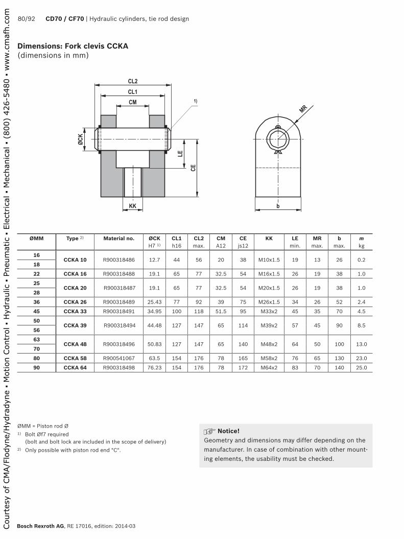
���
�� ��
���
���
��
��
��
��
�
80/92 CD70 / CF70 | Hydraulic cylinders, tie rod design
Bosch Rexroth AG, RE 17016, edition: 2014-03
Dimensions: Fork clevis CCKA (dimensions in mm)
ØMM = Piston rod Ø1) Bolt Øf7 required
(bolt and bolt lock are included in the scope of delivery)2) Only possible with piston rod end "C".
ØMM Type 2) Material no. ØCK H7 1)
CL1 h16
CL2 max.
CM A12
CE js12
KK LE min.
MR max.
b max.
m kg
16CCKA 10 R900318486 12.7 44 56 20 38 M10x1.5 19 13 26 0.2
18
22 CCKA 16 R900318488 19.1 65 77 32.5 54 M16x1.5 26 19 38 1.0
25CCKA 20 R900318487 19.1 65 77 32.5 54 M20x1.5 26 19 38 1.0
28
36 CCKA 26 R900318489 25.43 77 92 39 75 M26x1.5 34 26 52 2.4
45 CCKA 33 R900318491 34.95 100 118 51.5 95 M33x2 45 35 70 4.5
50CCKA 39 R900318494 44.48 127 147 65 114 M39x2 57 45 90 8.5
56
63CCKA 48 R900318496 50.83 127 147 65 140 M48x2 64 50 100 13.0
70
80 CCKA 58 R900541067 63.5 154 176 78 165 M58x2 76 65 130 23.0
90 CCKA 64 R900318498 76.23 154 176 78 172 M64x2 83 70 140 25.0
Notice!Geometry and dimensions may differ depending on the manufacturer. In case of combination with other mount-ing elements, the usability must be checked.
Court
esy
of CM
A/F
lodyn
e/H
ydra
dyn
e ▪
Motion C
ontr
ol ▪
Hyd
raulic
▪ P
neu
mat
ic ▪
Ele
ctrica
l ▪
Mec
han
ical
▪ (
800)
426-5
480 ▪
ww
w.c
maf
h.c
om

���
�
��
���
�
��
��
��
��
��
�
��
��
Hydraulic cylinders, tie rod design | CD70 / CG70 81/92
RE 17016, edition: 2014-03, Bosch Rexroth AG
Dimensions: Eye bearing block CLEA (dimensions in mm)
ØAL = Piston ØØMM = Piston rod Ø1) Lubricating nipple, cone head form A according to DIN 714122) Suitable for fork clevis type CCKA...3) When mounted on the cylinder base (type of mounting "G")4) When mounted on the piston rod with CCKA...
ØAL 3) ØMM 4) Type Material no. ØCK H7 2)
EM h13
FL js12
ØHB H13
ER max.
LE min.
UD max.
R js14
b m kg
3216
CLEA 10 R900318516 12.7 20 28.5 11 13 18.5 63 41.5 24 0.440
5018
63
80 22
CLEA 20 R900318518 19.1 32.5 47.5 13.5 22 31.5 89 65 40 1.6100 25
125 28
15036 CLEA 26 R900318519 25.43 39 57 17.5 30 38 114 82.5 55 2.3
200
— 45 CLEA 33 R900318520 34.95 51.5 76 17.5 41 54 127 97 75 5.8
—50
CLEA 39 R900318521 44.48 65 79.5 22 49 57 165 126 90 10.056
—63
CLEA 48 R900318522 50.83 65 89 26 56 64 190 145.5 105 14.070
— 80 CLEA 58 R900318524 63.53 78 101.5 30 69 77 216 167 130 21.0
— 90 CLEA 64 R900318523 76.23 78 108 33 77 83 242 190.5 145 26.0
Notice!Geometry and dimensions may differ depending on the manufacturer. In case of combination with other mount-ing elements, the usability must be checked.
Court
esy
of CM
A/F
lodyn
e/H
ydra
dyn
e ▪
Motion C
ontr
ol ▪
Hyd
raulic
▪ P
neu
mat
ic ▪
Ele
ctrica
l ▪
Mec
han
ical
▪ (
800)
426-5
480 ▪
ww
w.c
maf
h.c
om

�
�
�
82/92 CD70 / CF70 | Hydraulic cylinders, tie rod design
Bosch Rexroth AG, RE 17016, edition: 2014-03
ØAL in mm
ØMM in mm
Types of mounting:C, F, H, L, M, N, P, T
Types of mounting:D, K, Q
Operating pressure in bar Operating pressure in bar40 50 70 105 40 50 70 105
Maximum admissible stroke in mm Maximum admissible stroke in mm
2512 600 600 530 425 460 410 330 250
16 600 600 600 600 600 600 600 520
3218 800 800 800 800 580 500 420 325
22 800 800 800 800 800 760 630 500
25 800 800 800 800 800 800 800 745
4016 805 715 585 465 350 300 240 175
18 1000 920 770 610 450 390 320 250
25 1000 1000 1000 1000 900 780 635 500
5022 1200 1090 900 720 540 460 360 280
25 1200 1200 1200 965 765 670 550 430
36 1200 1200 1200 1200 1200 1200 1110 890
63
25 1255 1115 920 – 570 500 405 –
28 1400 1400 1130 – 700 610 490 –
36 1400 1400 1400 – 1310 1160 960 –
45 1400 1400 1400 – 1400 1400 1390 –
8036 1700 1700 1545 – 910 800 630 –
45 1700 1700 1700 – 1620 1435 1190 –
56 1700 1700 1700 – 1700 1700 1670 –
10045 2000 2000 1930 – 1170 1020 820 –
50 2000 2000 2000 – 1580 1395 1155 –
70 2000 2000 2000 – 2000 2000 2000 –
125
50 2300 2300 2300 – 1220 1075 885 –
56 2300 2300 2300 – 1470 1290 1140 –
63 2300 2300 2300 – 2035 1805 1500 –
90 2300 2300 2300 – 2300 2300 2300 –
150
63 2600 2600 – – 1670 1465 – –
70 2600 2600 – - 1890 1680 – –
80 2600 2600 – – 2600 2470 – –
100 2600 2600 – – 2600 2600 – –
20090 3000 – – – 2380 – – –
100 3000 – – – 3000 – – –
140 3000 – – – 3000 – – –
Admissible stroke lengths
adm
. str
oke
adm
. str
oke
sK = I • 12
sK = I • 12
adm
. str
oke
ØAL = Piston ØØMM = Piston rod Ø
Court
esy
of CM
A/F
lodyn
e/H
ydra
dyn
e ▪
Motion C
ontr
ol ▪
Hyd
raulic
▪ P
neu
mat
ic ▪
Ele
ctrica
l ▪
Mec
han
ical
▪ (
800)
426-5
480 ▪
ww
w.c
maf
h.c
om

�
�
Hydraulic cylinders, tie rod design | CD70 / CG70 83/92
RE 17016, edition: 2014-03, Bosch Rexroth AG
ØAL in mm
ØMM in mm
Types of mounting:B, G, S
Type of mounting: E(Position: Trunnion in cylinder center)
Operating pressure in bar Operating pressure in bar40 50 70 105 40 50 70 105
Maximum admissible stroke in mm Maximum admissible stroke in mm
2512 175 145 110 70 460 410 330 250
16 390 340 275 200 600 600 600 520
3218 390 340 300 200 580 500 420 325
22 600 550 450 335 800 760 630 500
25 800 745 615 480 800 800 800 690
4016 200 165 120 80 320 275 215 160
18 240 220 190 100 450 390 320 250
25 600 550 450 335 900 780 635 500
5022 375 300 245 170 540 460 360 280
25 480 420 335 250 700 615 500 390
36 1200 1000 820 700 1200 1200 1110 890
63
25 345 295 225 – 520 450 360 –
28 500 410 340 – 700 610 490 –
36 860 755 615 – 1205 1065 880 –
45 1400 1250 1000 – 1400 1400 1390 –
8036 680 580 420 – 680 580 420 –
45 1070 940 765 – 1495 1325 1095 –
56 1700 1500 1250 – 1700 1500 1250 –
10045 800 740 600 – 800 740 600 –
50 1030 900 730 – 1450 1275 1055 –
70 2000 1900 1600 – 2000 1900 1600 –
125
50 775 670 535 – 1120 985 805 –
56 1050 880 750 – 1050 880 750 –
63 1345 1185 965 – 1880 1665 1375 –
90 2300 2300 2200 – 2300 2300 2200 –
150
63 1065 925 – – 1525 1340 – –
70 1350 1220 – – 1350 1220 – –
80 1855 1635 – – 2580 2285 – –
100 2600 2600 – – 2600 2600 – –
20090 1750 – – – 1750 – – –
100 2175 – – – 3000 – – –
140 3000 – – – 3000 – – –
sK = I adm
. str
oke
Admissible stroke lengths
sK = I adm
. str
oke
ØAL = Piston ØØMM = Piston rod Ø
Court
esy
of CM
A/F
lodyn
e/H
ydra
dyn
e ▪
Motion C
ontr
ol ▪
Hyd
raulic
▪ P
neu
mat
ic ▪
Ele
ctrica
l ▪
Mec
han
ical
▪ (
800)
426-5
480 ▪
ww
w.c
maf
h.c
om
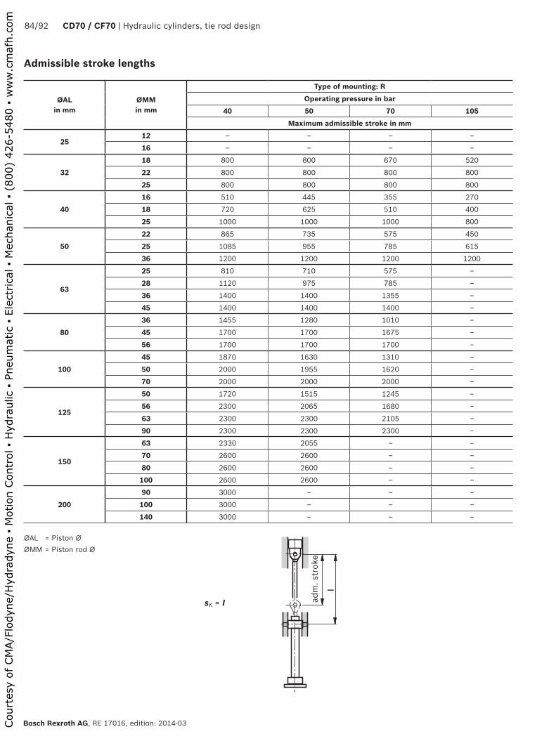
�
84/92 CD70 / CF70 | Hydraulic cylinders, tie rod design
Bosch Rexroth AG, RE 17016, edition: 2014-03
sK = I adm
. str
oke
Admissible stroke lengths
ØAL in mm
ØMM in mm
Type of mounting: ROperating pressure in bar
40 50 70 105Maximum admissible stroke in mm
2512 – – – –
16 – – – –
3218 800 800 670 520
22 800 800 800 800
25 800 800 800 800
4016 510 445 355 270
18 720 625 510 400
25 1000 1000 1000 800
5022 865 735 575 450
25 1085 955 785 615
36 1200 1200 1200 1200
63
25 810 710 575 –
28 1120 975 785 –
36 1400 1400 1355 –
45 1400 1400 1400 –
8036 1455 1280 1010 –
45 1700 1700 1675 –
56 1700 1700 1700 –
10045 1870 1630 1310 –
50 2000 1955 1620 –
70 2000 2000 2000 –
125
50 1720 1515 1245 –
56 2300 2065 1680 –
63 2300 2300 2105 –
90 2300 2300 2300 –
150
63 2330 2055 – –
70 2600 2600 – –
80 2600 2600 – –
100 2600 2600 – –
20090 3000 – – –
100 3000 – – –
140 3000 – – –
ØAL = Piston ØØMM = Piston rod Ø
Court
esy
of CM
A/F
lodyn
e/H
ydra
dyn
e ▪
Motion C
ontr
ol ▪
Hyd
raulic
▪ P
neu
mat
ic ▪
Ele
ctrica
l ▪
Mec
han
ical
▪ (
800)
426-5
480 ▪
ww
w.c
maf
h.c
om

� � � ��
Hydraulic cylinders, tie rod design | CD70 / CG70 85/92
RE 17016, edition: 2014-03, Bosch Rexroth AG
Kinking calculation
The kinking calculation is usually performed according to Euler as the piston rods are in most cases to be regarded as slim rods.
Kinking load K =π2 • E • J
in NsK2
i.e. with this load, the rod kinks!
Maximum operating load F =K
in NS
sK = Free kinking length in mmE = Module of elasticity in N/mm2 = 2.1 • 105 for steelJ = Moment of inertia in mm4 for circular cross-section
=d4 • π
= 0.0491 • d464
S = Safety (3.5)
Support width extension
With long strokes and pressure load, a support width extension is recommended in order to reduce the bearing load with extended piston rod. With this extension,
a spacer sleeve (3) is inserted between piston (1) and cylinder head (2). This spacer sleeve extends the lever arm and thus reduces the bearing load.
Without support width extension With support width extension
Guide distance Guide distance
Type of mounting
Ordering code for support width extension in mm for all piston Ø
– 25 50 75 100 125 150 175
Stroke length in mm
B, G, S up to 500 501 to 625 626 to 750 751 to 875 876 to 1000 1001 to 1125 1126 to 1250 1251 to 3000
C, F, H, L up to 1425 1426 to 1785 1786 to 2150 2151 to 2500 2501 to 2860 2861 to 3000 – –
D, E, K, Q up to 665 666 to 835 836 to 1000 1001 to 1165 1166 to 1335 1336 to 1500 1501 to 1665 1666 to 3000
R up to 1000 1001 to 1250 1251 to 1500 1501 to 1750 1751 to 2000 2001 to 2250 2251 to 2500 2501 to 3000
M, N, P, T up to 1425 1426 to 1785 1786 to 2150 2151 to 2500 2501 to 2860 2861 to 3000 – –
Installation length of the hydraulic cylinder with support width extension:Installation length according to the unit dimensions + support width extension(The trunnion position with type of mounting E and R will not be changed.)
Court
esy
of CM
A/F
lodyn
e/H
ydra
dyn
e ▪
Motion C
ontr
ol ▪
Hyd
raulic
▪ P
neu
mat
ic ▪
Ele
ctrica
l ▪
Mec
han
ical
▪ (
800)
426-5
480 ▪
ww
w.c
maf
h.c
om

��
�������
����
� �� �
��
��
��
�������
�����
�
� �
����
����
� �
� ��� �
���
��
��
����
�������
�������
86/92 CD70 / CF70 | Hydraulic cylinders, tie rod design
Bosch Rexroth AG, RE 17016, edition: 2014-03
Installation lengths and position tolerances
Stroke length in mm
up to 1250 1251 to 2000 2001 to 3000
Stroke tolerance in mm
+1 +1 +1
–1.5 –2 –3
WH ±2 ±2+3
–2
ZF ±1 ±1.5 ±2
XS ±2 ±2+3
–2
SS ±1.25+1.5 +1.5
–2 –3
XG ±2 ±2+3
–2
XV ±2 ±2 ±2
XJ ±2 ±2 ±2
XN ±1.25 ±2 ±2
Z 0.1 / 100
When ordering, always specify the "XV" dimension in the plain text (observe XVmin and XVmax)
X* = Stroke length
retr
acte
d
Court
esy
of CM
A/F
lodyn
e/H
ydra
dyn
e ▪
Motion C
ontr
ol ▪
Hyd
raulic
▪ P
neu
mat
ic ▪
Ele
ctrica
l ▪
Mec
han
ical
▪ (
800)
426-5
480 ▪
ww
w.c
maf
h.c
om
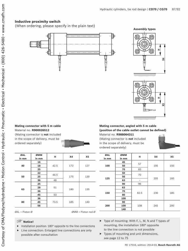
�
��
�
��
Hydraulic cylinders, tie rod design | CD70 / CG70 87/92
RE 17016, edition: 2014-03, Bosch Rexroth AG
Inductive proximity switch (When ordering, please specify in the plain text)
Mating connector with 5 m cable Material no. R900026512 (Mating connector is not included in the scope of delivery, must be ordered separately)
Mating connector, angled with 5 m cable (position of the cable outlet cannot be defined) Material no. R988064311 (Mating connector is not included in the scope of delivery, must be ordered separately)
Assembly types
ØAL in mm
ØMM in mm
H X4 X5
4016
42.5 172 1271825
5022
44.5175 13025
36 48
63
2551
180 135283645 53
8036
73.5 185 1404556
ØAL in mm
ØMM in mm
H X4 X5
10045
57195 15050
70 83
125
5070
205 1605663 –90 96
150
63
82.5 230 1857080100
20090
108 245 200100140
Notice! ▶ Installation position: 180° opposite to the line connections ▶ Line connection: Enlarged line connections are only
possible after consultation
▶ Type of mounting: With F, L, M, N and T types of mounting, the installation 180° opposite to the line connection is not possible
▶ Types of mounting and unit dimensions, see page 12 to 75
ØAL = Piston Ø ØMM = Piston rod Ø
Court
esy
of CM
A/F
lodyn
e/H
ydra
dyn
e ▪
Motion C
ontr
ol ▪
Hyd
raulic
▪ P
neu
mat
ic ▪
Ele
ctrica
l ▪
Mec
han
ical
▪ (
800)
426-5
480 ▪
ww
w.c
maf
h.c
om

�
�
�
�
�
��
��
88/92 CD70 / CF70 | Hydraulic cylinders, tie rod design
Bosch Rexroth AG, RE 17016, edition: 2014-03
Technical data (For applications outside these parameters, please consult us!)
Function type PNP normally open contact
Admissible pressure bar 500
Operating voltage V DC 10 … 30
Including residual ripple % ≤ 15
Voltage drop V ≤ 1.5
Rated operating voltage V DC 24
Rated operating current mA 200
Idle current mA ≤ 8
Residual current µA ≤ 10
Repetition accuracy % ≤ 5
Hysteresis % ≤ 15
Ambient temperature range °C –25 … +80
Temperature drift % ≤ 10
Switching frequency Hz 1000
Protection classActive area IP 68
Proximity switch IP 67
Housing material Material no. 1.4104
Proximity switch
Inductive proximity switches are used as reliable end position control for hydraulic cylinders. They are an impor-tant element for the safe and exact monitoring of safety equipment, locks and/or other machine functions in their end position by means of the output of signals. The prox-imity switch which is high-pressure resistant up to 500 bar
Pin assignment
BK
BU
BNBN brownBK blackBU blue
works in a contactless manner. Thus, it is wear-free. The proximity switch has been set at the factory. The switching distance must not be adjusted. The lock nut of the proxim-ity switch is marked at the factory using sealing wax. On versions with proximity switch, the hydraulic cylinders are equipped with proximity switches.
Court
esy
of CM
A/F
lodyn
e/H
ydra
dyn
e ▪
Motion C
ontr
ol ▪
Hyd
raulic
▪ P
neu
mat
ic ▪
Ele
ctrica
l ▪
Mec
han
ical
▪ (
800)
426-5
480 ▪
ww
w.c
maf
h.c
om
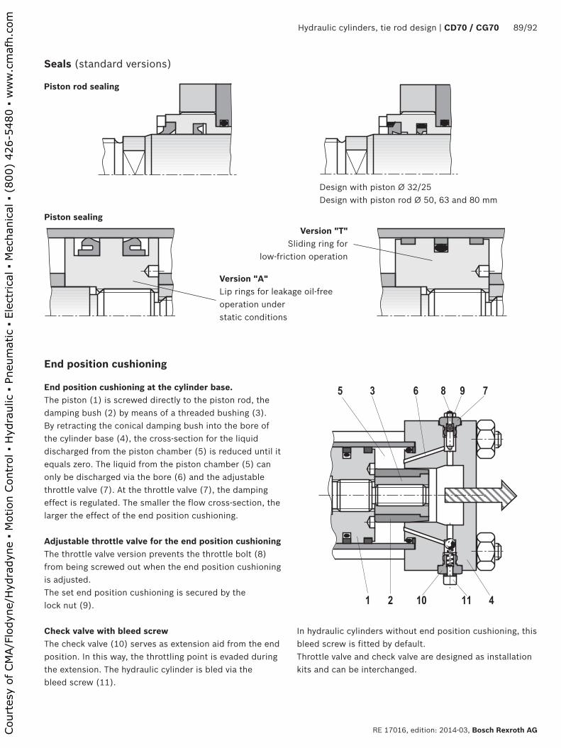
� � � � � �
� � �� �� �
Hydraulic cylinders, tie rod design | CD70 / CG70 89/92
RE 17016, edition: 2014-03, Bosch Rexroth AG
End position cushioning
End position cushioning at the cylinder base.The piston (1) is screwed directly to the piston rod, the damping bush (2) by means of a threaded bushing (3).By retracting the conical damping bush into the bore of the cylinder base (4), the cross-section for the liquid discharged from the piston chamber (5) is reduced until it equals zero. The liquid from the piston chamber (5) can only be discharged via the bore (6) and the adjustable throttle valve (7). At the throttle valve (7), the damping effect is regulated. The smaller the flow cross-section, the larger the effect of the end position cushioning.
Adjustable throttle valve for the end position cushioningThe throttle valve version prevents the throttle bolt (8) from being screwed out when the end position cushioning is adjusted.The set end position cushioning is secured by the lock nut (9).
Check valve with bleed screwThe check valve (10) serves as extension aid from the end position. In this way, the throttling point is evaded during the extension. The hydraulic cylinder is bled via the bleed screw (11).
Seals (standard versions)
Piston rod sealing
Piston sealingVersion "T"
Sliding ring for low-friction operation
Version "A"Lip rings for leakage oil-free operation under static conditions
Design with piston Ø 32/25 Design with piston rod Ø 50, 63 and 80 mm
In hydraulic cylinders without end position cushioning, this bleed screw is fitted by default.Throttle valve and check valve are designed as installation kits and can be interchanged.
Court
esy
of CM
A/F
lodyn
e/H
ydra
dyn
e ▪
Motion C
ontr
ol ▪
Hyd
raulic
▪ P
neu
mat
ic ▪
Ele
ctrica
l ▪
Mec
han
ical
▪ (
800)
426-5
480 ▪
ww
w.c
maf
h.c
om
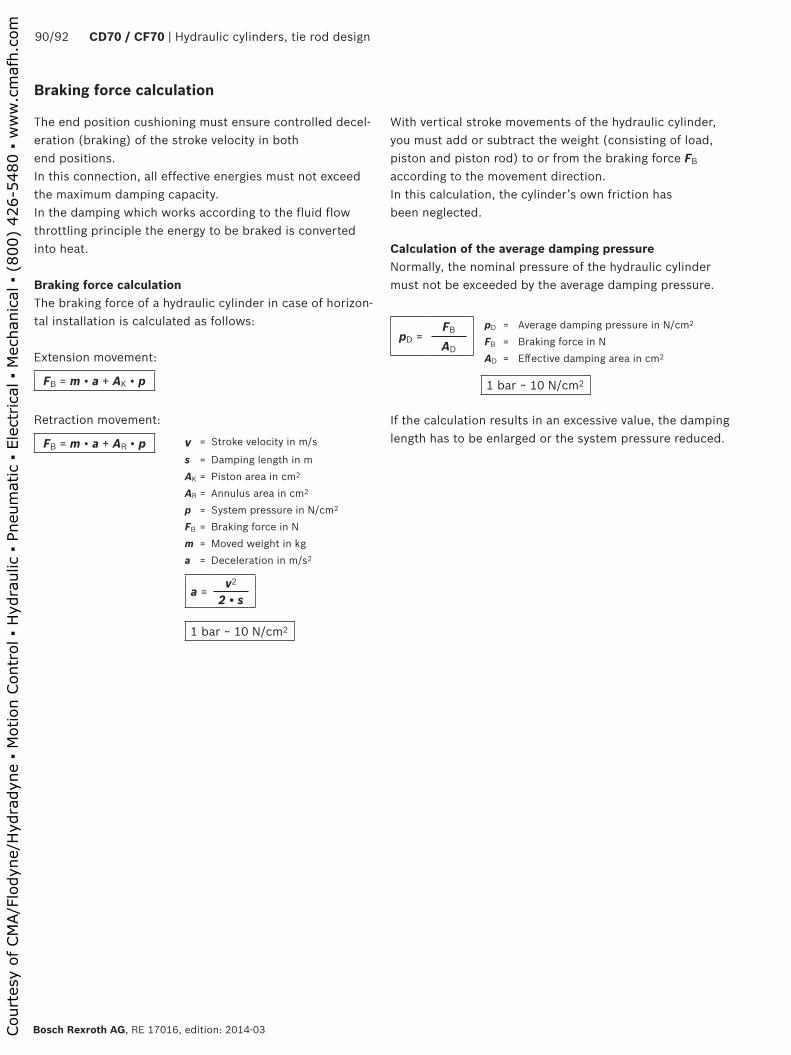
90/92 CD70 / CF70 | Hydraulic cylinders, tie rod design
Bosch Rexroth AG, RE 17016, edition: 2014-03
Braking force calculation
The end position cushioning must ensure controlled decel-eration (braking) of the stroke velocity in both end positions.In this connection, all effective energies must not exceed the maximum damping capacity.In the damping which works according to the fluid flow throttling principle the energy to be braked is converted into heat.
Braking force calculationThe braking force of a hydraulic cylinder in case of horizon-tal installation is calculated as follows:
Extension movement:
FB = m • a + AK • p
Retraction movement:
FB = m • a + AR • p v = Stroke velocity in m/s
s = Damping length in mAK = Piston area in cm2
AR = Annulus area in cm2
p = System pressure in N/cm2
FB = Braking force in Nm = Moved weight in kga = Deceleration in m/s2
a =v2
2 • s
1 bar ~ 10 N/cm2
With vertical stroke movements of the hydraulic cylinder, you must add or subtract the weight (consisting of load, piston and piston rod) to or from the braking force FB according to the movement direction.In this calculation, the cylinder’s own friction has been neglected.
Calculation of the average damping pressureNormally, the nominal pressure of the hydraulic cylinder must not be exceeded by the average damping pressure.
pD =FB
AD
pD = Average damping pressure in N/cm2
FB = Braking force in NAD = Effective damping area in cm2
1 bar ~ 10 N/cm2
If the calculation results in an excessive value, the damping length has to be enlarged or the system pressure reduced.
Court
esy
of CM
A/F
lodyn
e/H
ydra
dyn
e ▪
Motion C
ontr
ol ▪
Hyd
raulic
▪ P
neu
mat
ic ▪
Ele
ctrica
l ▪
Mec
han
ical
▪ (
800)
426-5
480 ▪
ww
w.c
maf
h.c
om
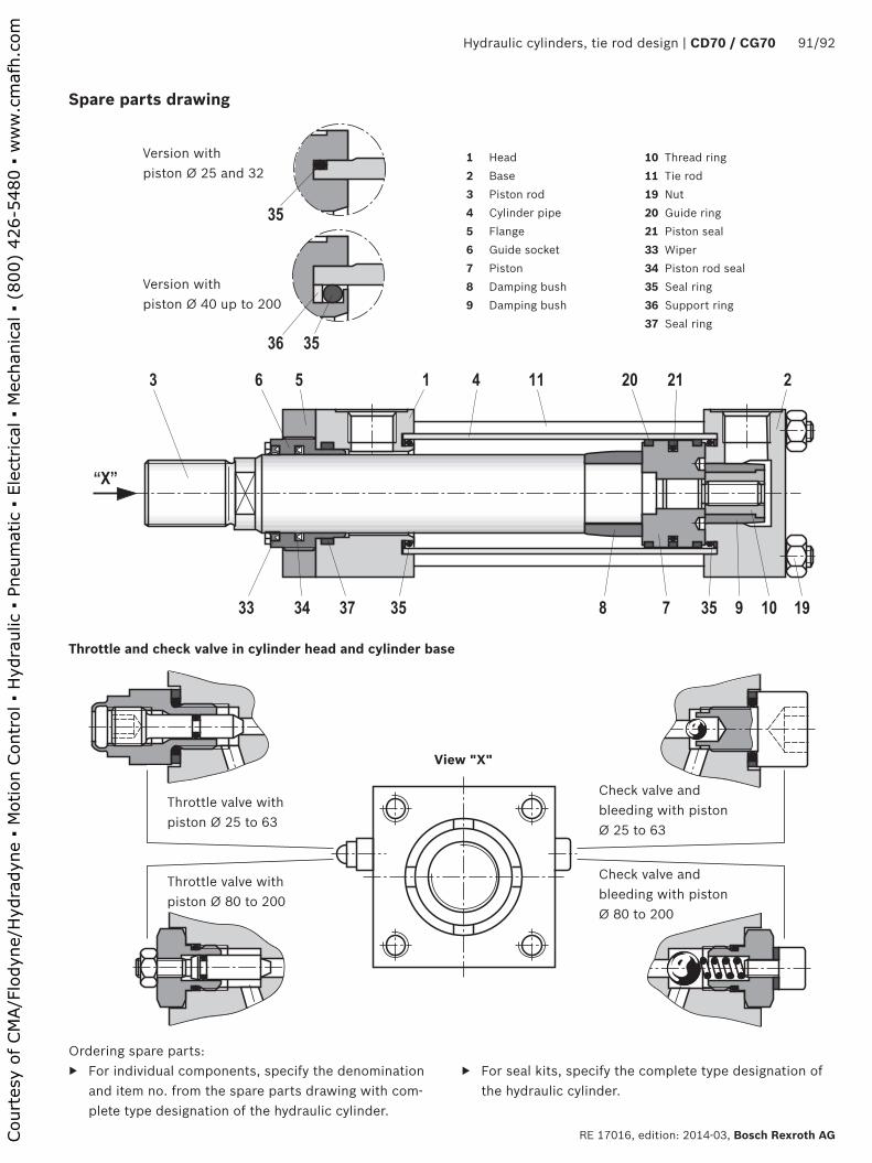
��
�� ��
� � � � � �� �� �� �
�� �� �� � � �� � �� ����
���
Hydraulic cylinders, tie rod design | CD70 / CG70 91/92
RE 17016, edition: 2014-03, Bosch Rexroth AG
Spare parts drawing
Throttle and check valve in cylinder head and cylinder base
Version withpiston Ø 40 up to 200
Version withpiston Ø 25 and 32
Ordering spare parts: ▶ For individual components, specify the denomination
and item no. from the spare parts drawing with com-plete type designation of the hydraulic cylinder.
1 Head2 Base3 Piston rod4 Cylinder pipe5 Flange6 Guide socket7 Piston8 Damping bush9 Damping bush
10 Thread ring11 Tie rod19 Nut20 Guide ring21 Piston seal33 Wiper34 Piston rod seal35 Seal ring36 Support ring37 Seal ring
Check valve and bleeding with piston Ø 25 to 63
View "X"
Throttle valve with piston Ø 25 to 63
Throttle valve with piston Ø 80 to 200
Check valve and bleeding with piston Ø 80 to 200
▶ For seal kits, specify the complete type designation of the hydraulic cylinder.
Court
esy
of CM
A/F
lodyn
e/H
ydra
dyn
e ▪
Motion C
ontr
ol ▪
Hyd
raulic
▪ P
neu
mat
ic ▪
Ele
ctrica
l ▪
Mec
han
ical
▪ (
800)
426-5
480 ▪
ww
w.c
maf
h.c
om
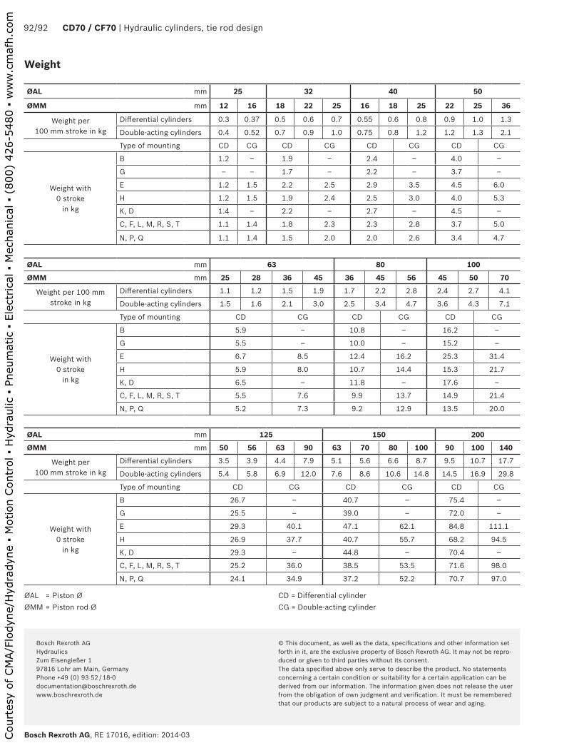
Bosch Rexroth AG, RE 17016, edition: 2014-03
92/92 CD70 / CF70 | Hydraulic cylinders, tie rod design
Bosch Rexroth AG HydraulicsZum Eisengießer 197816 Lohr am Main, Germany Phone +49 (0) 93 52 / 18-0 [email protected] www.boschrexroth.de
© This document, as well as the data, specifications and other information set forth in it, are the exclusive property of Bosch Rexroth AG. It may not be repro-duced or given to third parties without its consent.The data specified above only serve to describe the product. No statements concerning a certain condition or suitability for a certain application can be derived from our information. The information given does not release the user from the obligation of own judgment and verification. It must be remembered that our products are subject to a natural process of wear and aging.
Weight
ØAL mm 25 32 40 50
ØMM mm 12 16 18 22 25 16 18 25 22 25 36
Weight per 100 mm stroke in kg
Differential cylinders 0.3 0.37 0.5 0.6 0.7 0.55 0.6 0.8 0.9 1.0 1.3
Double-acting cylinders 0.4 0.52 0.7 0.9 1.0 0.75 0.8 1.2 1.2 1.3 2.1
Type of mounting CD CG CD CG CD CG CD CG
Weight with 0 stroke
in kg
B 1.2 – 1.9 – 2.4 – 4.0 –
G – – 1.7 – 2.2 – 3.7 –
E 1.2 1.5 2.2 2.5 2.9 3.5 4.5 6.0
H 1.2 1.5 1.9 2.4 2.5 3.0 4.0 5.3
K, D 1.4 – 2.2 – 2.7 – 4.5 –
C, F, L, M, R, S, T 1.1 1.4 1.8 2.3 2.3 2.8 3.7 5.0
N, P, Q 1.1 1.4 1.5 2.0 2.0 2.6 3.4 4.7
ØAL mm 63 80 100
ØMM mm 25 28 36 45 36 45 56 45 50 70
Weight per 100 mm stroke in kg
Differential cylinders 1.1 1.2 1.5 1.9 1.7 2.2 2.8 2.4 2.7 4.1
Double-acting cylinders 1.5 1.6 2.1 3.0 2.5 3.4 4.7 3.6 4.3 7.1
Type of mounting CD CG CD CG CD CG
Weight with 0 stroke
in kg
B 5.9 – 10.8 – 16.2 –
G 5.5 – 10.0 – 15.2 –
E 6.7 8.5 12.4 16.2 25.3 31.4
H 5.9 8.0 10.7 14.4 15.3 21.7
K, D 6.5 – 11.8 – 17.6 –
C, F, L, M, R, S, T 5.5 7.6 9.9 13.7 14.9 21.4
N, P, Q 5.2 7.3 9.2 12.9 13.5 20.0
ØAL mm 125 150 200
ØMM mm 50 56 63 90 63 70 80 100 90 100 140
Weight per 100 mm stroke in kg
Differential cylinders 3.5 3.9 4.4 7.9 5.1 5.6 6.6 8.7 9.5 10.7 17.7
Double-acting cylinders 5.4 5.8 6.9 12.0 7.6 8.6 10.6 14.8 14.5 16.9 29.8
Type of mounting CD CG CD CG CD CG
Weight with 0 stroke
in kg
B 26.7 – 40.7 – 75.4 –
G 25.5 – 39.0 – 72.0 –
E 29.3 40.1 47.1 62.1 84.8 111.1
H 26.9 37.7 40.7 55.7 68.2 94.5
K, D 29.3 – 44.8 – 70.4 –
C, F, L, M, R, S, T 25.2 36.0 38.5 53.5 71.6 98.0
N, P, Q 24.1 34.9 37.2 52.2 70.7 97.0
ØAL = Piston ØØMM = Piston rod Ø
CD = Differential cylinderCG = Double-acting cylinder
Court
esy
of CM
A/F
lodyn
e/H
ydra
dyn
e ▪
Motion C
ontr
ol ▪
Hyd
raulic
▪ P
neu
mat
ic ▪
Ele
ctrica
l ▪
Mec
han
ical
▪ (
800)
426-5
480 ▪
ww
w.c
maf
h.c
om