rapid platform network interface user guide - analog.com · rapid platform network interface user...
TRANSCRIPT

RapID Platform Network Interface User Guide September 1, 2015
UNCONTROLLED WHEN PRINTED OR COPIED
RapID Platform Network Interface
User Guide

RapID Platform Network Interface User Guide September 1, 2015
ii UNCONTROLLED WHEN PRINTED OR COPIED
Copyright 2017 by Innovasic, Inc.
Published by Innovasic, Inc. 5635 Jefferson St. NE, Suite A, Albuquerque, New Mexico 87109 USA
RapID Platform, PriorityChannel, and fido® are trademarks of Innovasic, Inc.

RapID Platform Network Interface User Guide September 1, 2015
iii UNCONTROLLED WHEN PRINTED OR COPIED
TABLE OF CONTENTS
Overview ..........................................................................................................................................1
1.1 Network Interface Evaluation Kit .................................................................................1
1.2 Evaluation and Development ........................................................................................2
2. Connecting the Evaluation Kit Hardware ...............................................................................4
2.1 ESD and Power Supply Considerations ........................................................................4
2.1.1 Electrostatic Sensitive Device ..........................................................................4
2.1.2 Power Supply and Grounding ...........................................................................4
2.2 Making the Connections ................................................................................................4

RapID Platform Network Interface User Guide September 1, 2015
iv UNCONTROLLED WHEN PRINTED OR COPIED
LIST OF FIGURES
Figure 1- NIEK Included Materials .................................................................................................2
Figure 2- Evaluation and Development Overview ..........................................................................3
Figure 3 – Module and Baseboard Connection Detail Snapshot .....................................................4
Figure 4 – USB Cable Connection...................................................................................................5
Figure 5 – Power Cable Connection ................................................................................................5
Figure 6 – Ethernet Cable Connection .............................................................................................6
Figure 7 – Power ON Switch location .............................................................................................6
Figure 8 – Test Network Set-up ..................................................... Error! Bookmark not defined.
Figure 9 – Test Network Set-up for DLR ...................................... Error! Bookmark not defined.

RapID Platform Network Interface User Guide September 1, 2015
1 UNCONTROLLED WHEN PRINTED OR COPIED
Overview
Thank you for purchasing the RapID Platform Network Interface Evaluation Kit. Innovasic
appreciates your interest in the RapID Platform – EtherNet/IP Network Interface and RapID
Platform – EtherNet/IP Network Interface with DLR. Please contact us at any time to answer
questions, help with set-up, or discuss ideas to make integration easy. Helping get your product
to market efficiently and effectively is what our support team does best.
1.1 Network Interface Evaluation Kit
The RapID Platform Network Interface solutions are pre-tested Industrial Network interfaces
that manage the industrial protocol and network traffic. Thanks to the module’s Unified
Interface, a single host interface hardware and software design supports PROFINET, PROFINET
IRT, PROFIBUS, EtherNet/IP, EtherNet/IP with DLR, EtherCAT, and ModbusTCP. Choose the
type of Network Interface to support the required Industrial protocols. The Unified Interface
also ensures your host processor hardware or software interface does not need to change even
when you switch or update protocols. The Network Interface connects to a host processor via a
UART, 16-bit Parallel Interface, or Ethernet (future).
The evaluation kit provides a quick assessment for interfacing a host processor to the Network
Interface module (module is sold separately). Once host-side communication is established,
communication can be evaluated using third-party PC-based tools or vendor-specific
Programmable Logic Controllers (PLC). The communication path between the host processor
and a PLC can be completely verified before integrating the Network Interface into your end
field device. Please take a moment to verify the contents of your evaluation kit.
Network Interface Evaluation Kit Contents:
a. Network Interface Baseboard
b. UART Personality Module
c. Parallel Interface Personality Module
d. Ethernet Personality Module (Future)
e. Power Supply with outlet adapters
f. Ethernet Cable
g. USB Cable
h. Innovasic Developer Portal Information Card

RapID Platform Network Interface User Guide September 1, 2015
2 UNCONTROLLED WHEN PRINTED OR COPIED
Figure 1- NIEK Included Materials
1.2 Evaluation and Development
The purpose of the RapID Platform Network Interface Evaluation Kit is to provide an end-to-end
evaluation of the communication path from the host processor to the PLC. This document
describes how to use the kit to set-up and run an EtherNet/IP application example. The
application example demonstrates an end-to-end communication from a host processor to a PLC.

RapID Platform Network Interface User Guide September 1, 2015
3 UNCONTROLLED WHEN PRINTED OR COPIED
For the example described in this Quick Start Guide, the host processor is a PC and
communicates to the Network Interface via a USB. Communication to the PLC is over the
Industrial Ethernet interface using EtherNet/IP. A Rockwell PLC will be used to perform
EtherNet/IP communication.
After running the application example, the reader will be ready to transition to the development
phase of a project. It is intended that the kit and application example be used along with the
Design Integration Guide to develop field device products. Figure 2 provides an overview of the
evaluation and development process. There are detailed documents to help complete a field
device design using the Network Interface. These documents are referenced in the Design
Integration Guide.
Figure 2- Evaluation and Development Overview
RapID Platform Network Interface User Guide September 1, 2015
4 UNCONTROLLED WHEN PRINTED OR COPIED
2. Connecting the Evaluation Kit Hardware
This section describes how to connect the hardware provided in the Evaluation Kit. The steps
below use a PC with USB as a host processor and a PLC with an EtherNet/IP Industrial Ethernet
interface. Separate guides are available for other protocols.
2.1 ESD and Power Supply Considerations
2.1.1 Electrostatic Sensitive Device
The hardware should be handled in accordance with proper ESD device-handling techniques.
Personnel using this board are advised to use their grounding wrist strap to prevent accidental
damage to the hardware.
2.1.2 Power Supply and Grounding
A wall adapter power supply is included with your evaluation boards. This supply is 12V, 1A and attaches to the power supply barrel connector. There is also a screw terminal to attached a lab benchtop power supply. For either type of power supply connection, the input voltage to the board must be in the range of 9V to 33V.
2.2 Making the Connections
Setting up the hardware is a simple five step process. At the end of these five steps, the
baseboard and module with connections should look similar to Figure 3. The Evaluation Kit
ships with the correct jumpers installed so there is no need to set any jumpers. There is also no
need to set any switches. The UART Interface, Parallel Interface, or Ethernet Interface
Personality Modules are not used in this set up procedure.
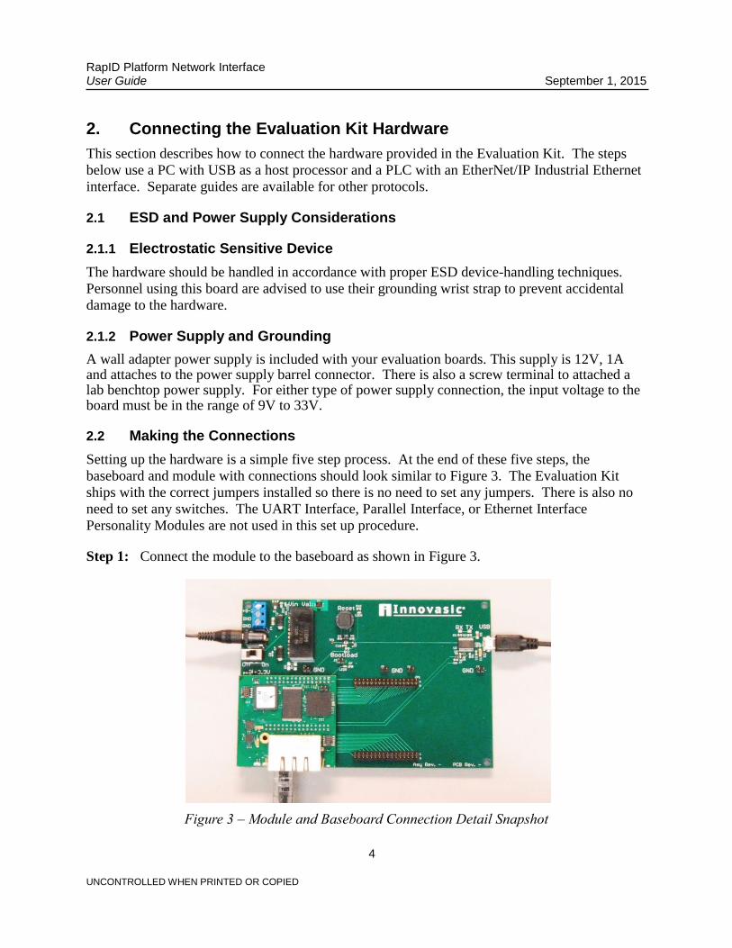
Step 1: Connect the module to the baseboard as shown in Figure 3.
Figure 3 – Module and Baseboard Connection Detail Snapshot

RapID Platform Network Interface User Guide September 1, 2015
5 UNCONTROLLED WHEN PRINTED OR COPIED
Step 2: Connect the USB Cable from your PC to the baseboard. This will create two virtual
COM Ports on your PC that will be used later in the application example.
Figure 4 – USB Cable Connection
Step 3: Connect the power cable provided in the kit to the “POWER” port. The detailed
location of the power port on the baseboard is shown below. Plug the other end of the
power cord into a wall socket.
Figure 5 – Power Cable Connection

RapID Platform Network Interface User Guide September 1, 2015
6 UNCONTROLLED WHEN PRINTED OR COPIED
Step 4: Connect one end of the provided Ethernet cable in the kit to either of the RJ45 jacks on
the Network Interface module. The detailed location of the RJ45 jacks is shown below.
Connect the other end of the Ethernet cable to the PLC. Then connect the PLC to your
PC via Ethernet.
Figure 6 – Ethernet Cable Connection
Step 5: Apply power to the module by turning the Network Interface module baseboard power
switch to the “ON” position. The detailed location of the switch on the baseboard is
shown below.
Figure 7 – Power ON Switch location