ranger™ 4000 count series - danvaegt
TRANSCRIPT

Ranger™ 4000 Count Series
Instruction Manual


Ranger™ 4000 Count Series EN 1
1. INTRODUCTION This manual contains installation, operation and maintenance instructions for the Ranger™ Count 4000 Series. Please read the manual completely before using the scale.
1.1 Definition of Signal Warnings and Symbols Safety notes are marked with signal words and warning symbols. These show safety issues and warnings. Ignoring the safety notes may lead to personal injury, damage to the instrument, malfunctions and false results.
Signal Words
WARNING For a hazardous situation with medium risk, possibly resulting in injuries or
death if not avoided.
CAUTION for a hazardous situation with low risk, resulting in damage to the device or
the property or in loss of data, or injuries if not avoided.
Note (No symbol)
For useful information about the product
Warning Symbols
General Hazard Electrical Shock Hazard
Alternating Current
1.2 Safety Precautions Please follow these safety precautions:
Verify that the AC input voltage printed on the data label matches the local AC power supply.
Only connect the power cord to a compatible grounded electrical outlet.
Do not position the scale such that it is difficult to disconnect the power cord from the power
receptacle.
This scale is for indoor use only.
Use the scale in dry locations only.
Do not drop loads on the platform.
Make sure that the power cord does not pose a potential obstacle or tripping hazard.
Use only approved accessories and peripherals.
Operate the scale only under ambient conditions specified in these instructions.
Disconnect the scale from the power supply when cleaning.
Do not operate the scale in hazardous or unstable environments.
Do not immerse the scale in water or other liquids.
Do not place the scale upside down on the platform.
Only use weights within the scale’s capacity as specified in these instructions.
Service should be performed only by authorized personnel.

EN 2 Ranger™ 4000 Count Series
2. INSTALLATION 2.1 Package Contents
Scale
Pan
Power Cord
Sub-platform
Instruction Manual / CD
Warranty Card
2.2 Installing Components Install the sub-platform & metal pan as shown below. Press to lock the sub-platform into place. The scale can be operated without the pan, if desired.
Figure 2-1. Installing sub-platform and metal pan
2.3 Selecting the Location Use the scale on a firm, steady surface. Avoid locations with excessive air current, vibrations, heat sources, or rapid temperature changes. Allow sufficient space around the scale.
2.4 Leveling the Equipment The Ranger Count Series has a level indicator as a reminder that the scale should be leveled for accurate weighing. To level the scale, adjust the feet so the bubble is centered in the circle. Be sure the equipment is level each time its location is changed.
Figure 2-2. Level indicator
Level Indicator
Adjustable feet

Ranger™ 4000 Count Series EN 3
2.5 Connecting Power AC power is used to power the scale when battery power is not needed. First, connect the AC power cord (supplied) to the power input receptacle then connect the AC plug to an electrical outlet.
2.5.1 Battery Power:
The scale can be used on AC power immediately. Allow the battery to charge for 12 hours before using the scale on battery power. The scale will automatically switch to battery operation if there is a power failure or the power cord is removed. With AC power, the scale is constantly charging, so the battery charge indicator (see item 10 in figure 3-2) will remain lit. The scale can be operated during charging, and the battery is protected against overcharging. During battery operation, the battery symbol indicates the battery charge level. The scale will automatically turn off when the batteries are fully discharged. For maximum operating time, the battery should be charged at room temperature.
TABLE 2-1
Symbol Charge Level
0 to 10 % Remaining
11 to 40 % Remaining
41 to 70 % Remaining
71 to 100 % Remaining
Notes:
When battery symbol blinks fast, approximately 30 minutes working time is left.
When [lo.bat] is displayed, the scale will shut off.
Charging the scale must be performed in a dry environment.
CAUTION: Battery is to be replaced only by an authorized Ohaus service dealer. Risk of explosion can occur if the rechargeable battery is replaced with the wrong type or if it is not properly connected. Dispose of the lead acid battery according to local laws and regulations.
Figure 2-3B. Connect the AC power plug to the proper AC supply.
Figure 2-3A. Connect the AC power plug to the input receptacle on the back of scale.

EN 4 Ranger™ 4000 Count Series
3. OPERATION 3.1 Displays
Figure 3-1. Ranger Count 4000 Control panel with LCD displays
TABLE 3-1. Control Functions
Button
Primary Function
(Short Press1)
ON/ZERO
Turn scale on.
Zero the display.
Send the displayed value to the
COM port.
Target
Initiate the function of the current application mode.
M+
Accumulate the weight or pieces.
ID
ID number input for library record edit/recall.
APW
Display/ Store an APW
Secondary Function
(Long Press2)
Off Turn scale off.
Units Change the weighing unit.
Switch between Check Weigh, Check Count and Off.
Menu Enter user menu. View the Audit Trail event counters (extended
press)
Menu Function (Short Press)
Yes Accept the current menu or setting.
No Advance to the next menu or setting. Increment the displayed value.
Back Go back to the previous menu or setting. Decrement the displayed value.
Exit Exit the menu. Abort the calibration in progress.
Library Function
(Short Press)
Yes
Accept the current setting.
No
Advance to the next library or setting. Increment the displayed value.
Back
Go back to the previous library or setting. Decrement the displayed
value.
Exit
Exit the library.
Ranger™ 4000 Count Series EN 5
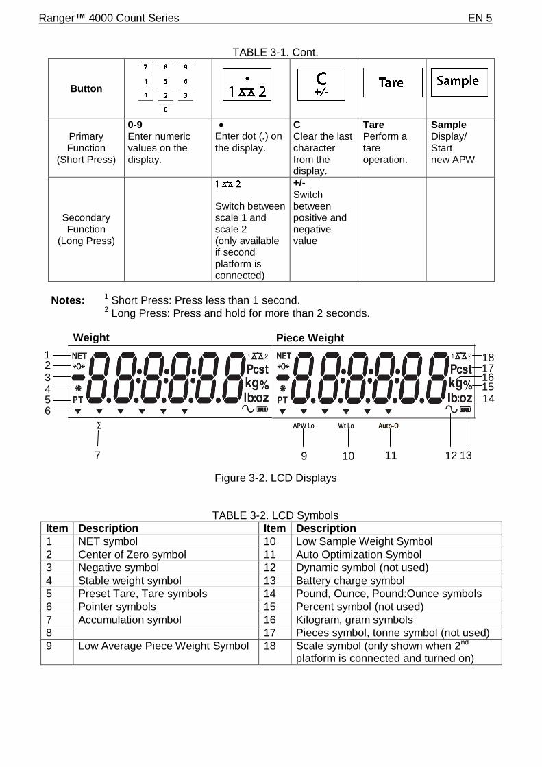
TABLE 3-1. Cont.
Button
Primary Function
(Short Press)
0-9 Enter numeric values on the display.
Enter dot (.) on
the display.
C Clear the last character from the display.
Tare Perform a tare operation.
Sample Display/ Start new APW
Secondary Function
(Long Press)
Switch between scale 1 and scale 2 (only available if second platform is connected)
+/-
Switch between positive and negative value
Notes: 1 Short Press: Press less than 1 second.
2 Long Press: Press and hold for more than 2 seconds.
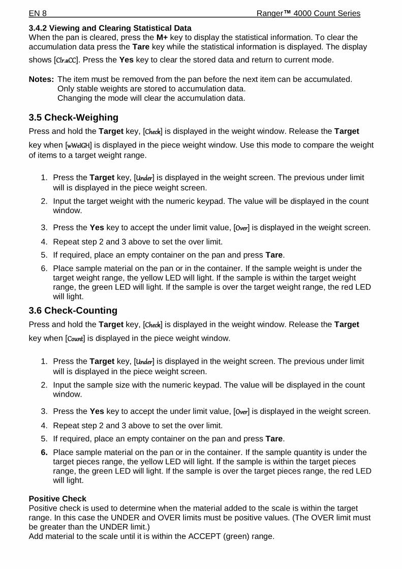
TABLE 3-2. LCD Symbols
Item Description Item Description
1 NET symbol 10 Low Sample Weight Symbol
2 Center of Zero symbol 11 Auto Optimization Symbol
3 Negative symbol 12 Dynamic symbol (not used)
4 Stable weight symbol 13 Battery charge symbol
5 Preset Tare, Tare symbols 14 Pound, Ounce, Pound:Ounce symbols
6 Pointer symbols 15 Percent symbol (not used)
7 Accumulation symbol 16 Kilogram, gram symbols
8 17 Pieces symbol, tonne symbol (not used)
9 Low Average Piece Weight Symbol 18 Scale symbol (only shown when 2nd platform is connected and turned on)
1
7 10 11 12 13
14 15
Figure 3-2. LCD Displays
.
2 3 4 5 6
9
16 17 18
Piece Weight Weight

EN 6 Ranger™ 4000 Count Series
The colored LED indicators on the left side of the control panel are used in Checkweigh mode (section 3.7) and will light up according to the following rules:
(Red) Loads > Upper limit
(Green) Loads ≥ Lower limit and ≤ Upper limit
(Yellow) Loads < Lower limit
Figure 3-3. Below view of Ranger Count 4000
3.2 Turning Scale On/Off To turn the scale on, press and hold the On/Zero Off button for 1 second. The scale performs a
display test, momentarily displays the software version, and then enters the active weighing mode. To turn the scale off, press and hold the On/Zero Off button until OFF is displayed.
3.3 Counting Ranger Count 4000 has three display areas. Weight, Piece Weight and Count information are displayed in these areas respectively. 3.3.1 Preset tare Enter a value with the numeric keypad. The value will be displayed in the Count window. Pressing Tare key, the value in current unit will then be saved as the preset tare. To clear the tare value, clear the pan and press Tare key. 3.3.2 APW Establishment
If there is no APW established, both the piece weight display and the count display will show 0.
Power Input
Weigh Below Access
Lock Switch
RS232 and Option Interface Port
(below cover)
Battery Chamber

Ranger™ 4000 Count Series EN 7
Positive Sampling:
1. Place the sample on the pan.
2. Input the sample size with the numeric keypad. The value is displayed in the count window.
Alternatively the Sample key can be used instead. Pressing the Sample key and
[------] is displayed in the count window. Then input the sample size value (only integer).
3. Press the Sample key, [------] will be displayed in both the piece window and the count
window.
4. The established APW and count will be displayed.
Negative sampling:
1. Place container with the samples on the pan.
2. Tare the scale, a NET 0 will be displayed.
3. Remove the samples from the container; weight window will now display a negative net reading.
4. Input the sample size with the numeric keypad. The value will be displayed in the count window.
Alternatively the Sample key can be used instead. Pressing the Sample key and [-
-----] is displayed in the count window. Then input the sample size value (only integer).
5. Press the Sample key, [------] will be displayed in both the piece window and the count
window.
6. The established APW and count will be displayed.
Entering a known APW:
1. Press the APW key, [------] will be displayed in the piece window
2. Input the APW value.
3. Press the APW key, the new APW value will be displayed in piece weight window.
3.3.3 Simple Counting
1. After a valid APW is established, if required place a container on the pan and press Tare.
2. Place the sample on the pan.
3. The quantity will be displayed in the count window.
3.4 Accumulation and Statistics The Accumulation feature enables manual or automatic totalizing of displayed values. Statistical data is stored in memory for review and printing. Accumulation works together with Check mode. 3.4.1 Accumulating Displayed Values With ACCUMULATE set to MANUAL, place the item on the scale and press the M+ key to add
the weight to accumulation data. The ∑ icon will keep flashing until the weight is removed. With ACCUMULATE set to AUTO, place the item on the scale. The displayed value is accumulated automatically. The ∑ icon will keep flashing until the weight is removed.
EN 8 Ranger™ 4000 Count Series
3.4.2 Viewing and Clearing Statistical Data When the pan is cleared, press the M+ key to display the statistical information. To clear the accumulation data press the Tare key while the statistical information is displayed. The display
shows [Clr.aCC]. Press the Yes key to clear the stored data and return to current mode.
Notes: The item must be removed from the pan before the next item can be accumulated. Only stable weights are stored to accumulation data.
Changing the mode will clear the accumulation data.
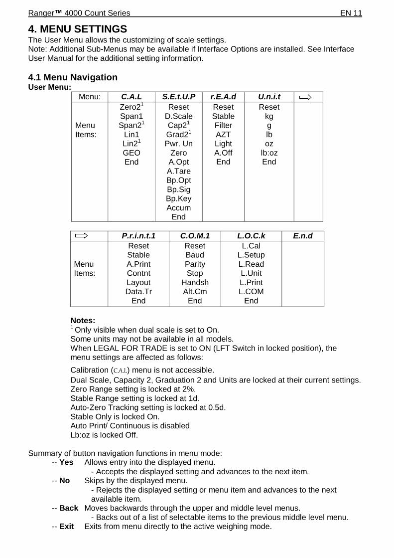
3.5 Check-Weighing
Press and hold the Target key, [Check] is displayed in the weight window. Release the Target
key when [wWeIGH] is displayed in the piece weight window. Use this mode to compare the weight
of items to a target weight range.
1. Press the Target key, [Under] is displayed in the weight screen. The previous under limit
will is displayed in the piece weight screen.
2. Input the target weight with the numeric keypad. The value will be displayed in the count window.
3. Press the Yes key to accept the under limit value, [Over] is displayed in the weight screen.
4. Repeat step 2 and 3 above to set the over limit.
5. If required, place an empty container on the pan and press Tare.
6. Place sample material on the pan or in the container. If the sample weight is under the target weight range, the yellow LED will light. If the sample is within the target weight range, the green LED will light. If the sample is over the target weight range, the red LED will light.
3.6 Check-Counting
Press and hold the Target key, [Check] is displayed in the weight window. Release the Target
key when [Count] is displayed in the piece weight window.
1. Press the Target key, [Under] is displayed in the weight screen. The previous under limit
will is displayed in the piece weight screen.
2. Input the sample size with the numeric keypad. The value will be displayed in the count window.
3. Press the Yes key to accept the under limit value, [Over] is displayed in the weight screen.
4. Repeat step 2 and 3 above to set the over limit.
5. If required, place an empty container on the pan and press Tare.
6. Place sample material on the pan or in the container. If the sample quantity is under the target pieces range, the yellow LED will light. If the sample is within the target pieces range, the green LED will light. If the sample is over the target pieces range, the red LED will light.
Positive Check Positive check is used to determine when the material added to the scale is within the target range. In this case the UNDER and OVER limits must be positive values. (The OVER limit must be greater than the UNDER limit.) Add material to the scale until it is within the ACCEPT (green) range.

Ranger™ 4000 Count Series EN 9
Negative Check
Negative check is used to determine when the material removed from the scale is within the target range. In this case the UNDER and OVER limits are both negative values. (The UNDER limit must be greater than the OVER limit.) Place the item to be weighed on the scale and press Tare.
Remove a portion of the item until it is within the ACCEPT range. Zero Check Zero check is used when comparing subsequent samples to an initial reference sample. In this case, the UNDER limit must be a negative value and the OVER limit must be a positive value. Place the reference item on the scale and press Tare. Remove the reference sample and place
the item to be compared on the scale to determine if it is within the ACCEPT range.
3.7 Library When an item is processed on a regular basis, the item’s data may be stored in memory for future use. This memory is referred to as the scale’s Library. Storing a record:
1. Press the ID key, [Store] and [lib] are displayed in the weight and piece weight
windows respectively. The first vacant ID number will blink in the count window. 2. Press ID key to save the data to the displayed ID number. Alternately, a different ID number may be selected using the keypad and then pressing the ID key.
Note: Maximum 30 records, from 0 to 29. Retrieving a record:
1. Enter the ID number using the keypad and press the ID key. [reCall] and [lib] are
displayed in the weight and piece weight windows respectively. 2. ID number is displayed in the weight window.
3. Press the ID or Yes key, [reCall] is displayed and the data is retrieved.
Editing a record:
1. Enter the ID number using the keypad and press the ID key. [reCall] and [lib] are
displayed in the weight and piece weight windows respectively.
2. Long press the ID key, [edit] and [lib] are momentarily displayed in the weight and
piece weight windows respectively. 3. Part number is displayed in the weight and piece weight windows. Default setting is
[000000] [000000]. Use the keypad to enter part number if required.
4. Press the Yes key to save the part number and advance to the preset Tare setting.
Use the keypad to enter a preset Tare value if required. 5. Press the Yes key to save the preset Tare value and advance to the APW setting.
Use the keypad to enter a new APW value if required. 6. Press the Yes key to save the APW and advance to the Limits setting.
Use the keypad to enter new under and over limits if required.
7. Press the Yes key to save the limits. [save] is displayed in the weight window. Press
the Yes key to save the data.
Clearing a record:

EN 10 Ranger™ 4000 Count Series
1. Enter the ID number using the keypad and press the ID key. [reCall] and [lib] are
displayed in the weight and piece weight windows respectively.
2. Press the C key, [delete] is displayed in the weight window. Press the Yes key to
delete the data.
Ranger™ 4000 Count Series EN 11
4. MENU SETTINGS The User Menu allows the customizing of scale settings. Note: Additional Sub-Menus may be available if Interface Options are installed. See Interface User Manual for the additional setting information.
4.1 Menu Navigation User Menu:
Menu: C.A.L S.E.t.U.P r.E.A.d U.n.i.t
Menu Items:
Zero21
Span1 Span21
Lin1
Lin21
GEO End
Reset D.Scale Cap21
Grad21
Pwr. Un Zero A.Opt A.Tare Bp.Opt Bp.Sig Bp.Key Accum
End
Reset Stable Filter AZT Light A.Off End
Reset kg g lb oz
lb:oz End
P.r.i.n.t.1 C.O.M.1 L.O.C.k E.n.d
Menu Items:
Reset Stable A.Print Contnt Layout Data.Tr
End
Reset Baud Parity Stop
Handsh Alt.Cm
End
L.Cal L.Setup L.Read L.Unit L.Print L.COM
End
Notes: 1 Only visible when dual scale is set to On. Some units may not be available in all models. When LEGAL FOR TRADE is set to ON (LFT Switch in locked position), the menu settings are affected as follows:
Calibration (C.A.L) menu is not accessible.
Dual Scale, Capacity 2, Graduation 2 and Units are locked at their current settings. Zero Range setting is locked at 2%. Stable Range setting is locked at 1d. Auto-Zero Tracking setting is locked at 0.5d. Stable Only is locked On. Auto Print/ Continuous is disabled Lb:oz is locked Off. Summary of button navigation functions in menu mode: -- Yes Allows entry into the displayed menu.
- Accepts the displayed setting and advances to the next item. -- No Skips by the displayed menu.
- Rejects the displayed setting or menu item and advances to the next available item. -- Back Moves backwards through the upper and middle level menus. - Backs out of a list of selectable items to the previous middle level menu. -- Exit Exits from menu directly to the active weighing mode.

EN 12 Ranger™ 4000 Count Series
For menu items with numeric settings such as Capacity, the current setting is displayed with all digits flashing. Press the No button to begin editing. The first digit is displayed flashing. Press the No button to increment the digit or press the Yes button to accept the digit and move to the next digit.
Repeat this process for all digits.
Press the Yes button when the last digit has been set.
The new setting is displayed with all digits flashing. Press the Yes button to accept the setting or press the No button to resume editing.
This method also applies to setting Checkweigh under and over targets.
For End menu items, pressing the Yes button advances to the next menu, while pressing the No button returns to the top of the current menu.
4.2 Cal Menu Enter this menu to perform calibrations. Initial Calibration When the scale is operated for the first time, a span calibration is recommended to ensure accurate weighing results. Before performing the calibration, be sure to have the appropriate calibration weights as listed in table 4-1. Ensure that the LFT switch/calibration lock is set to unlocked position. See figure 5-1.
Or adjust the GEO setting according to your location (see table 4-2).
Procedure:
Press and hold Menu until [mMeNU] (Menu) is displayed. When the button is released, the display
will show [C.A.L]. Press Yes to accept. [SpaN] will then be shown. Press Yes to begin the span
calibration. [ 0 kg] will be displayed. Press Yes to accept. [--C--] will be displayed while zero
reading is stored. Next, the display shows the calibration weight value. Place the specified calibration mass on the pan. Press Yes to accept the weight or No to select an alternate weight.
[--C--] will be displayed while the reading is stored. The display will show [done] if the calibration
was successful. The scale returns to the previous application mode and is ready for use.
TABLE 4-1
Required Span Calibration Mass (sold separately)
Capacity Mass1 Capacity Mass
1
3000g 3kg / 6lb 15000g 15kg / 30lb
6000g 6kg / 15lb 30000g 30kg / 60lb
Note: 1 Pound masses are used when calibrating in the lb unit.

Ranger™ 4000 Count Series EN 13
Zero2 [ZErO] Initiates a 2nd scale zero calibration.
Span1 [SpaN] Initiates a span calibration procedure (zero and span). A span calibration is important when initially setting up the scale.
Span2 [SpaN2] Initiates a 2nd scale span calibration procedure.
Lin1 [LIN] Initiates a linearity calibration procedure (zero, mid-point and span).
Lin2 [LIN2] Initiates a 2nd scale linearity calibration procedure.
GEO [GEO] Geographical Adjustment Factor (GEO) is used to adjust the calibration based on the current location. Settings from 0 to 31 are available with 12 being the default. Refer to table 4-2 to determine the GEO factor that corresponds to your location.
End Cal [End]
Advance to the next menu or return to the top of the current menu.
4.3 Setup Menu Enter this menu to set scale parameters.
Reset: no, yes Dual Scale: off, on Cap2: 1…9999
Grad2: 0.00005…0.5 Power on unit: auto, kg, g, lb, oz, lb:oz Zero Range: 2%, 10% Auto Opt: off, on Auto Tare: on, off, on-acc Beeper Opt: off, on Beeper Signal: off, accept, under, over, under-over Beeper Key: off, on Accumulation: off, auto, manual
End Setup: Exit menu
Zero2: Perform Span1: Perform Span2: Perform Linearity1: Perform Linearity2: Perform Geographic Adjustment: Set 0…12…31*
End Calibration: Exit menu *Bold always represents factory default value.

EN 14 Ranger™ 4000 Count Series
Reset [reset] Reset the Setup menu to factory defaults. NO = not reset YES = reset
Dual Scale [d.scale] Set the status of the second scale input (Scale 2). OFF = disabled ON = enabled
Cap2 [CAP2] Set the capacity of Scale 2. 1…9999
Grad2 [GrAd2] Set the readability of Scale 2. 0.00005…0.5
Power on unit [pwWr.UN] Set the unit of measure displayed at startup. AUTO = last unit in use when turned off kg = kilograms g = grams lb = pounds oz = ounces lb:oz = pound ounces
Zero Range [ZErO] Set the percentage of scale capacity that may be zeroed. 2% = zero up to 2 percent of capacity 10% = zero up to 10 percent of capacity
Auto Opt [A.OPt] Set the Automatic Optimization. OFF = disabled ON = APW automatically optimized
Auto Tare [A.tArE] Set the automatic tare functionality. OFF = Automatic Tare is disabled ON = the first stable gross weight is tared ON-ACC = stable gross loads within the accept limits are tared (in Check weighing mode)
Beeper Opt [bp.OPt] Set whether or not the beeper sounds when APW has been optimized. OFF = disabled

Ranger™ 4000 Count Series EN 15
ON = enabled
Beeper Signal [Bp.sIG] Set how the beeper responds in Check Weighing mode. OFF = the beeper is disabled ACCEPT = the beeper will sound when the weight is within the Accept range. UNDER = the beeper will sound when the weight is below the Under setting. OVER- UNDER = the beeper will sound when the weight is above the Over setting. OVER = the beeper will sound when the weight is below the Under setting or above the Over setting.
Beeper Key [BP.key] Set whether the beeper sounds when a button is pressed. OFF = no sound ON = sound
Accumulation [aCCUmM] Set the accumulation functionality. OFF = accumulation disabled AUTO = automatic accumulation MAN = manual accumulation
End Setup [End]
Advance to the next menu or return to the top of the current menu.
4.4 Readout Menu Enter this menu to set user preferences.
Reset [reset] Reset the Read menu to factory defaults. NO = not reset YES = reset
Stable Range [Stable] Set the amount the reading can vary while the stability symbol remains on. 0.5d = 0.5 scale division 1d = 1 scale division 2d = 2 scale division 5d = 5 scale division
Reset: no, yes Stable Range: 0.5, 1, 2, 5 Filter: low, medium, high Auto-Zero Tracking: off, 0.5, 1, 3 Light: off, on, auto Auto off: off, 1, 5, 10
End Readout: Exit menu

EN 16 Ranger™ 4000 Count Series
Filter [FILtEr] Set the amount of signal filtering. LOW = less stability, faster stabilization time MED = normal stability, stabilization time HI = greater stability, slower stabilization time
AZT [AZt] Set the automatic zero tracking functionality. OFF = disabled 0.5d = the display will maintain zero until a change of 0.5 divisions per second has been exceeded. 1d = the display will maintain zero until a change of 1 divisions per second has been exceeded. 3d = the display will maintain zero until a change of 3 divisions per second has been exceeded.
Light [LIGHt] Sets backlight functionality. OFF = always off ON = always on AUTO = turns on when a button is pressed or the displayed weight changes.
Auto off [A.OFF] Set the automatic shut off functionality. OFF = disabled 1 = powers off after 1 minute of no activity 5 = powers off after 5 minute of no activity 10 = powers off after 10 minute of no activity
End Readout [End] Advance to the next menu or return to the top of the current menu.
4.5 Unit Menu This sub-menu activates units so they will be accessible with the Units button. The units in the menu must be turned “on” to be active. Note: Available units vary by model and local regulations.
4.6 Print1 Menu Enter this menu to set printing parameters. Default settings are bold. Note: The Print2 menu is only displayed if a second interface is installed.
Reset: no, yes Stable Only: off, on Auto Print: off, on stable, interval, continuous, accept Content: P/N (-> off, on) Result (-> off, on)
Gross (-> off, on) Net (-> off, on) Tare (-> off, on) Header (-> off, on) Footer (-> off, on) Mode (-> off, on) Unit (-> off, on)
Info (-> off, on) APW (-> off, on) Acc (-> off, result, all) Layout: Format (->S,M)

Ranger™ 4000 Count Series EN 17
Reset [reset] Reset the Print menu to factory defaults. NO = no reset YES = reset
Stable Only [Stable] Set the printing criteria. OFF = values are printed immediately ON = values are only printed when the stability criteria are met
Auto Print [A.Print] Set the automatic printing functionality. OFF = disabled ON.STAB = printing occurs each time the stability criteria are met INTER = printing occurs at the defined interval ACCEPT = printing occurs continuously CONT = printing occurs each time the display is within the Checkweigh accept range and stability criteria are met.
Content [CONtNt] Define the content of the printed data. Part Number Set the status. OFF = disabled ON = enabled Result Set the status. OFF = disabled ON = the displayed reading is printed
Gross
Set the status. OFF = disabled ON = the gross weight is printed Net Set the status. OFF = disabled ON = the net weight is printed Tare
Set the status.

EN 18 Ranger™ 4000 Count Series
OFF = disabled ON = the Tare weight is printed Header
Set the status. OFF = disabled ON = the Header is printed
Note: See section 7.3.1 for how to enter Header line. Footer Set the status. OFF = disabled ON = the Footer is printed
Note: See section 7.3.1 for how to enter Footer line. Mode Set the status. OFF = disabled ON = the Mode is printed Unit
Set the status. OFF = disabled ON = the Unit is printed Info Set the status. OFF = disabled ON = the reference information is printed
APW
Set the status. OFF = disabled ON = enabled
Accu Set the status. OFF = disabled RESULT = the Accumulation result is printed
ALL = all the Accumulation data is printed
Layout [layOUt] Set the format of the data output to a printer or computer. Format Set the printing format. MULTI = a multi-line (single column style) printout is generated. SINGLE = a single line printout is generated. Feed
Set the paper feed. LINE = move a paper up one line after printing 4LF = move a paper up four lines after printing FORM = a form feed is appended to the printout

Ranger™ 4000 Count Series EN 19
Data Transfer [data.tr] Output weighing results directly to a PC application. OFF = disabled ON = enabled Windows XP Setup:
1. Click Start Menu in Windows XP and click Settings -> open Control Panel. 2. Double click Accessibility Options in Control Panel. 3. Select the General tab. 4. Check Use Serial Keys, and click the Settings button. 5. Select the Serial Port, set the Baud rate to 9600 and click OK. 6. Close the Control Panel. 7. Run Excel to open one blank sheet. Focus the cursor on one item. At this time, if scale sends data to the PC through the RS232 port, the data will be put into the cell, and the cursor will automatically move to the next vertical cell.
Notes: For Windows 7 setup, contact Ohaus. If the weighing value is a negative number, set the target cell in TEXT format. Otherwise, Excel will not distinguish it as a negative number. Please do not use this function during continuous printing.
Print Library [P.lib]
Print the library data. No = disabled Yes = All library records stored in memory are printed
End Print [End] Advance to the next menu or return to the top of the current menu.
4.7 COM1 Menu Enter this menu to define communication parameters Note: The COM2 menu is only displayed if a second interface is installed.
Reset [reset] Reset the COM menu to factory defaults. NO = no reset YES = reset
Baud Rate [BAUD] Set the baud rate. 300 = 300 bps 600 = 600 bps
Reset: no, yes Baud Rate: 300…9600…19200 Parity: 7 even, 7 odd, 7 none, 8 none Stop bit: 1, 2 Handshake: none, On-Off Alternate command: Print (A…P…Z), Tare (A…T…Z), Zero (A…Z)
End COM: Exit menu

EN 20 Ranger™ 4000 Count Series
1200 = 1200 bps 2400 = 2400 bps 4800 = 4800 bps 9600 = 9600 bps 19200 = 19200 bps
Parity [paritY] Set the data bits and parity. 7 EVEN = 7 data bits, even parity 7 ODD = 7 data bits, odd parity 7 NONE = 7 data bits, no parity 8 NONE = 8 data bits, no parity
Stop bit [stOP] Set the number of stop bits. 1 = 1 stop bits 2 = 2 stop bits
Handshake [H.shake] Set the flow control method. Hardware handshaking is only available for COM1 menu. NONE = no handshaking ON-OFF = XON/XOFF software handshaking
Alternate command [Alt.CmM] Define command character for the Print, Tare and Zero commands
Set the alternate command character for Print A to Z.
Tare Set the alternate command character for Tare A to Z.
Zero Set the alternate command character for Zero. A to Z.
End COM1, End COM2 [End] Advance to the next menu or return to the top of the current menu.
4.8 Lock Menu The Lock Menu is a software controlled option which can lock Menu settings to prevent tampering.
Reset [reset]
Reset no, yes Lock Cal off, on Lock Setup off, on Lock Read off, on Lock Unit off, on Lock Print off, on Lock COM off, on
End Menu Lock Exit menu

Ranger™ 4000 Count Series EN 21
Reset the Lock menu to factory defaults. NO = no reset YES = reset
Lock Cal [l.CAL] Set the status. OFF = Calibration menu is not locked ON = Calibration menu is locked
Lock Setup Set the status. OFF = Setup menu is not locked ON = Setup menu is locked
Lock Read Set the status. OFF = Readout menu is not locked ON = Readout menu is locked
Lock Unit [l.Unit] Set the status. OFF = Unit menu is not locked ON = Unit menu is locked
Lock Print Set the status. OFF = Print menu is not locked ON = Print menu is locked
Lock COM [l.COmM] Set the status. OFF = COM menu is not locked ON = COM menu is locked
End Lock [End] – Advance to the next menu or return to the top of the current menu.
4.9 End Menu Press ‘Yes’ to advance to the Calibration menu. Press ‘No’ to exit the menu and return to the current application mode.
4.10 Additional Features To use this feature, remove AC power from the scale and remove the protective cover for the weigh below opening. Install a suitable hook into the access hole at the bottom of the scale as shown. Do not over tighten, tighten finger tight. Mount the scale onto an appropriate assembly that allows free working space below the hook. See figure 4-1. Refer to section 6.4 for optional hook.
Note: Never allow the scale to rest directly on the hook.

EN 22 Ranger™ 4000 Count Series
Figure 4-1. Setup for the Weigh Below Hook
Weigh Below Hook
Access

Ranger™ 4000 Count Series EN 23
TABLE 4-2. GEO CODES
0 325 650 975 1300 1625 1950 2275 2600 2925 3250
325 650 975 1300 1625 1950 2275 2600 2925 3250 3575
0 1060 2130 3200 4260 5330 6400 7460 8530 9600 10660
1060 2130 3200 4260 5330 6400 7460 8530 9600 10660 11730
0°00' 5°46' 5 4 4 3 3 2 2 1 1 0 0
5°46' 9°52' 5 5 4 4 3 3 2 2 1 1 0
9°52' 12°44' 6 5 5 4 4 3 3 2 2 1 1
12°44' 15°06' 6 6 5 5 4 4 3 3 2 2 1
15°06' 17°10' 7 6 6 5 5 4 4 3 3 2 2
17°10' 19°02' 7 7 6 6 5 5 4 4 3 3 2
19°02' 20°45' 8 7 7 6 6 5 5 4 4 3 3
20°45' 22°22' 8 8 7 7 6 6 5 5 4 4 3
22°22' 23°54' 9 8 8 7 7 6 6 5 5 4 4
23°54' 25°21' 9 9 8 8 7 7 6 6 5 5 4
25°21' 26°45' 10 9 9 8 8 7 7 6 6 5 5
26°45' 28°06' 10 10 9 9 8 8 7 7 6 6 5
28°06' 29°25' 11 10 10 9 9 8 8 7 7 6 6
29°25' 30°41' 11 11 10 10 9 9 8 8 7 7 6
30°41' 31°56' 12 11 11 10 10 9 9 8 8 7 7
31°56' 33°09' 12 12 11 11 10 10 9 9 8 8 7
33°09' 34°21' 13 12 12 11 11 10 10 9 9 8 8
34°21' 35°31' 13 13 12 12 11 11 10 10 9 9 8
35°31' 36°41' 14 13 13 12 12 11 11 10 10 9 9
36°41' 37°50' 14 14 13 13 12 12 11 11 10 10 9
37°50' 38°58' 15 14 14 13 13 12 12 11 11 10 10
38°58' 40°05' 15 15 14 14 13 13 12 12 11 11 10
40°05' 41°12' 16 15 15 14 14 13 13 12 12 11 11
41°12' 42°19' 16 16 15 15 14 14 13 13 12 12 11
42°19' 43°26' 17 16 16 15 15 14 14 13 13 12 12
43°26' 44°32' 17 17 16 16 15 15 14 14 13 13 12
44°32' 45°38' 18 17 17 16 16 15 15 14 14 13 13
45°38' 46°45' 18 18 17 17 16 16 15 15 14 14 13
46°45' 47°51' 19 18 18 17 17 16 16 15 15 14 14
47°51' 48°58' 19 19 18 18 17 17 16 16 15 15 14
48°58' 50°06' 20 19 19 18 18 17 17 16 16 15 15
50°06' 51°13' 20 20 19 19 18 18 17 17 16 16 15
51°13' 52°22' 21 20 20 19 19 18 18 17 17 16 16
52°22' 53°31' 21 21 20 20 19 19 18 18 17 17 16
53°31' 54°41' 22 21 21 20 20 19 19 18 18 17 17
54°41' 55°52' 22 22 21 21 20 20 19 19 18 18 17
55°52' 57°04' 23 22 22 21 21 20 20 19 19 18 18
57°04' 58°17' 23 23 22 22 21 21 20 20 19 19 18
58°17' 59°32' 24 23 23 22 22 21 21 20 20 19 19
59°32' 60°49' 24 24 23 23 22 22 21 21 20 20 19
60°49' 62°90' 25 24 24 23 23 22 22 21 21 20 20
62°90' 63°30' 25 25 24 24 23 23 22 22 21 21 20
63°30' 64°55' 26 25 25 24 24 23 23 22 22 21 21
64°55' 66°24' 26 26 25 25 24 24 23 23 22 22 21
66°24' 67°57' 27 26 26 25 25 24 24 23 23 22 22
67°57' 69°35' 27 27 26 26 25 25 24 24 23 23 22
69°35' 71°21' 28 27 27 26 26 25 25 24 24 23 23
71°21' 73°16' 28 28 27 27 26 26 25 25 24 24 23
73°16' 75°24' 29 28 28 27 27 26 26 25 25 24 24
75°24' 77°52' 29 29 28 28 27 27 26 26 25 25 24
77°52' 80°56' 30 29 29 28 28 27 27 26 26 25 25
80°56' 85°45' 30 30 29 29 28 28 27 27 26 26 25
85°45' 90°00' 31 30 30 29 29 28 28 27 27 26 26
Elevation in meters
Elevation in feet
GEO valueLatitude

EN 24 Ranger™ 4000 Count Series
5. LEGAL FOR TRADE When the scale is used in trade or a legally controlled application it must be set up, verified and sealed in accordance with local weights and measures regulations. It is the responsibility of the purchaser to ensure that all pertinent legal requirements are met.
5.1 Capacity Label A label showing the capacity and readability of the scale must be installed near each display. If the Capacity Labels were installed prior to delivery, no further action is needed. If the Capacity Labels were not installed, they have been placed in the packaging material. Affix the labels above the displays as shown in Figure 5-1.
Note: The Capacity Labels will be destroyed upon removal, so only attempt to install them once.
Figure 5-1. Capacity Label location
5.2 Settings Before verification and sealing, perform the following steps: 1. Verify that the menu settings meet the local weights and measures regulations. 2. Perform a calibration as explained in Section 3.9. 3. Set the switch to Locked. See figure 5-1. The Menu Lock switch limits changes to the Cal, Setup, Readout, Unit and Print menus. The switch in type approved models may set some scale settings as required by the approval agency. The switch may be secured using paper seals, wire seals or plastic ties. Note: When LEGAL FOR TRADE is set to ON (LFT Switch in locked position), the menu settings are affected as follows:
Calibration (C.A.L) menu is not accessible
Dual Scale, Capacity 2, Graduation 2 and Units are locked at their current settings Zero Range setting is locked at 2% Stable Range setting is locked at 1d Auto-Zero Tracking setting is locked at 0.5d Stable Only is locked On Auto Print/ Continuous is disabled Lb:oz is locked Offf
5.2 Verification and Sealing The local weights and measures official or authorized service agent must perform the verification procedure.
5.3.1 Physical Seals
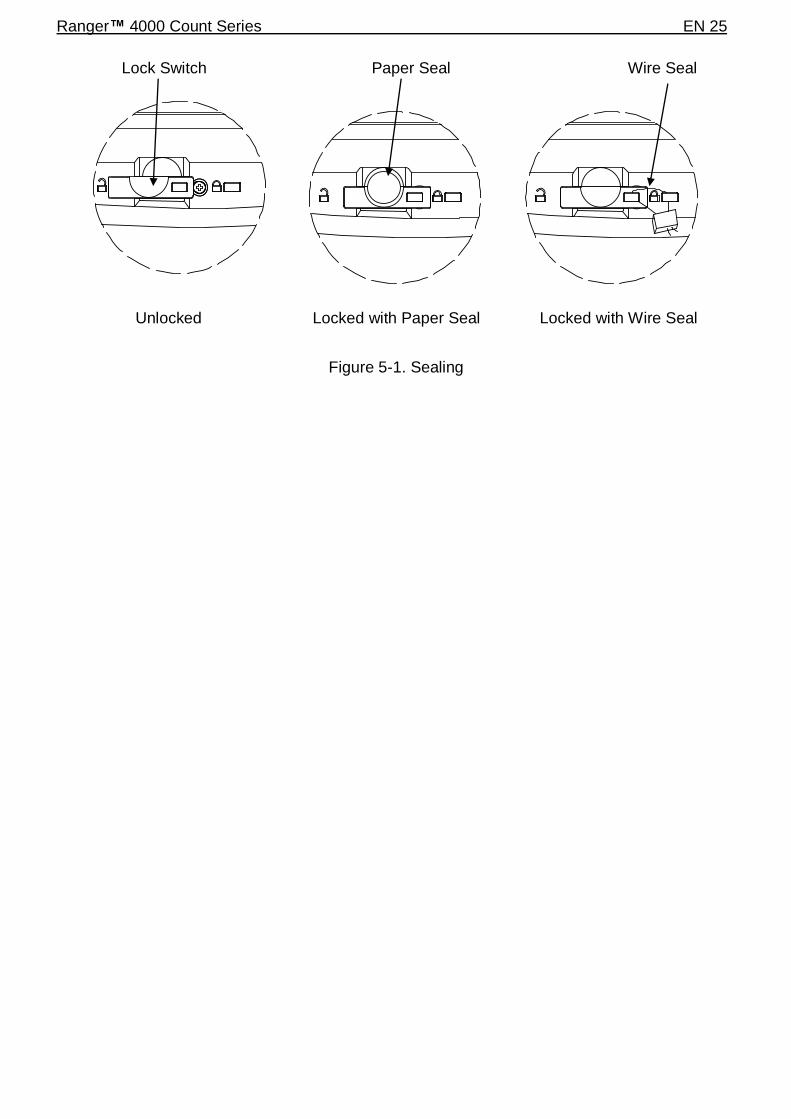
For jurisdictions that use the physical sealing method, the local weights and measures official or authorized service agent must apply a security seal to prevent tampering with the settings. Refer to the illustration below for sealing methods.
Capacity Label
Ranger™ 4000 Count Series EN 25
Figure 5-1. Sealing
Unlocked Locked with Paper Seal Locked with Wire Seal
Paper Seal Wire Seal Lock Switch

EN 26 Ranger™ 4000 Count Series
6. MAINTENANCE 6.1 Cleaning
WARNING: Electric Shock Hazard. Disconnect the scale from the power supply before cleaning. Make sure that no liquid enters the interior of the scale during cleaning.
The housing may be cleaned with a cloth dampened with a mild detergent if necessary.
Attention: Do not use solvents, chemicals, alcohol, ammonia or abrasives to clean the housing
or control panel.
6.2 Troubleshooting Table 6-1 lists common problems and possible causes and remedies. If the problem persists, contact OHAUS or your authorized dealer.
TABLE 6-1
Symptom Possible Cause Remedy
Cannot turn on No power to scale Verify connections and voltage
Poor accuracy Improper calibration Unstable environment
Perform calibration Move scale to suitable location
Cannot calibrate Unstable environment Incorrect calibration weight
Move the scale to suitable location Use correct calibration weight
Cannot access mode Mode not enabled Enter menu and enable mode
Cannot access unit Unit not enabled Enter menu and enable unit
Battery icon flashing Battery is empty Connect the scale to AC power and charge the battery
Err 8.1 Power On Error Weight reading exceeds Power On Zero limit
Err 8.2 Power On Error Weight reading below Power On Zero limit
Err 8.3 Over Range Error Weight reading exceeds Overload limit
Err 8.4 Under Range Error Weight reading below Underload limit
Err 8.5 Tare out of range Adjust tare value to be within range
Err 8.6 Display overflow Weight exceeds 6 digits
Err 9.5 Calibration data error Calibration data not present
------- Busy Displayed during tare setting, zero setting, printing
--NO-- Action not allowed Function not executed
CAL E
Calibration error Unstable environment Incorrect calibration weight
Calibration value outside allowed limits Move the scale to suitable location Use correct calibration weight
Lo.REF Low reference weight warning Increase reference weight.
rEF.Err Unacceptable reference weight
Reference weight too small. Weight on the pan is too small to define a valid reference weight. Increase reference weight.
Battery fails to charge fully
Battery is defective Have battery replaced by Ohaus authorized service dealer.
6.3 Service Information If the troubleshooting section does not resolve or describe your problem, contact your authorized OHAUS service agent. For service assistance or technical support in the United States call toll-free 1-800-526-0659 between 8:00 AM and 5:00 PM EST. An OHAUS product service specialist will be available to provide assistance. Outside the USA, please visit our web site, www.ohaus.com to locate the OHAUS office nearest you.

Ranger™ 4000 Count Series EN 27
6.4 Accessories 2nd scale Interface Kit 30037446 Ethernet Interface Kit 30037447 2nd RS232 Interface Kit 30037448 USB Interface Kit 30037449 In Use Cover 30240697 Weigh Below Hook 30025993 Printer Contact Ohaus Communication Cables Contact Ohaus
7. TECHNICAL DATA The technical data is valid under the following ambient conditions: Indoor use only Operating temperature: -10°C to 40°C Relative humidity: maximum relative humidity 80 % for temperatures up to 30 °C decreasing linearly to 50 % relative humidity at 40 °C Altitude: Up to 2000 m Power: AC power 100-240V 50/60 Hz, internal rechargeable sealed lead-acid battery Mains supply voltage fluctuations: up to ± 10% of the nominal voltage Pollution degree: 2 Installation category: II
7.1 Specifications
TABLE 7-1
MODEL RC41M3 RC41M6 RC41M15 RC41M30
Capacity x Readability (Max x d non-approved)
3 kg x 0.0001 kg 3000 g x 0.1 g 6 lb x 0.0002 lb
96 oz x 0.003 oz
6 kg x 0.0002 kg 6000 g x 0.2 g
15 lb x 0.0004 lb 240 oz x 0.006 oz
15 kg x 0.0005 kg 15000 g x 0.5 g 30 lb x 0.001 lb 480 ox x 0.02 oz
30 kg x 0.001 kg 30000 g x 1
g 60 lb x 0.002 lb 960 oz x 0.04
oz
Maximum Displayed Resolution
1:30000
Minimum Recommended Sample Weight
2g / 0.004lb 4g / 0.01lb 10g / 0.02lb 20g / 0.04lb
Minimum Recommended APW
0.01g / 0.00002lb 0.02g / 0.00005lb 0.05g / 0.0001lb 0.1 g / 0.0002lb
Capacity x Readability (Max x e approved)
3 kg x 0.001 kg 3000 g x 1 g
6 lb x 0.002 lb 96 oz x 0.03 oz
6 kg x 0.002 kg 6000 g x 2 g
15 lb x 0.004 lb 240 oz x 0.06 oz
15 kg x 0.005 kg 15000 g x 5 g 30 lb x 0.01 lb
480 ox x 0.2 oz
30 kg x 0.01 kg 30000 g x 10 g 60 lb x 0.02 lb 960 oz x 0.4 oz
Approved Resolution 1:3000
Repeatability 0.0002 kg 0.0005 kg 0.001 kg 0.002 kg
Linearity 0.0002 kg 0.0005 kg 0.001 kg 0.002 kg
Weighing Units Non-Approved models: g, kg, lb, oz, lb:oz
EC and OIML Approved models: g, kg Measurement Canada and NTEP Approved models: g, kg, lb, oz
Tare Range To capacity by subtraction
Stabilization Time ≤ 1 second
Weight Display 3 LCD with white LED backlight
6-digit 7-segment, 20.5 mm / 0.8 in in characters
Keyboard 20 mechanical buttons
Battery Operating Time (at 20ºC)
210 hours with backlight turned off
Construction ABS plastic housing with 304 stainless steel (SST) platform
Approval Class III
Pan Dimensions 225 x 300 mm
EN 28 Ranger™ 4000 Count Series
Net Weight 5.9 kg / 13 lb
Gross Weight 7.2 kg / 15.9 lb
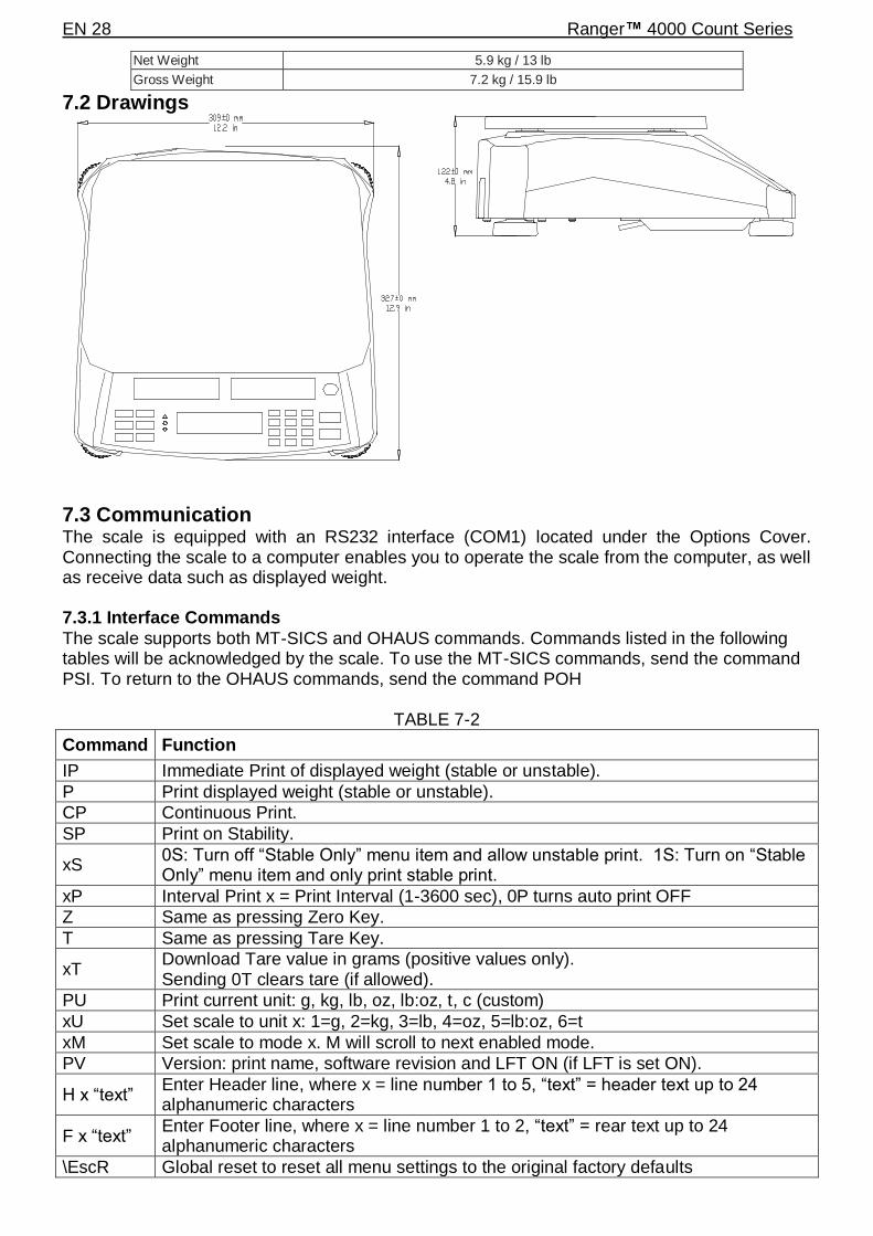
7.2 Drawings
7.3 Communication The scale is equipped with an RS232 interface (COM1) located under the Options Cover. Connecting the scale to a computer enables you to operate the scale from the computer, as well as receive data such as displayed weight. 7.3.1 Interface Commands
The scale supports both MT-SICS and OHAUS commands. Commands listed in the following tables will be acknowledged by the scale. To use the MT-SICS commands, send the command PSI. To return to the OHAUS commands, send the command POH
TABLE 7-2
Command Function
IP Immediate Print of displayed weight (stable or unstable).
P Print displayed weight (stable or unstable).
CP Continuous Print.
SP Print on Stability.
xS 0S: Turn off “Stable Only” menu item and allow unstable print. 1S: Turn on “Stable Only” menu item and only print stable print.
xP Interval Print x = Print Interval (1-3600 sec), 0P turns auto print OFF
Z Same as pressing Zero Key.
T Same as pressing Tare Key.
xT Download Tare value in grams (positive values only). Sending 0T clears tare (if allowed).
PU Print current unit: g, kg, lb, oz, lb:oz, t, c (custom)
xU Set scale to unit x: 1=g, 2=kg, 3=lb, 4=oz, 5=lb:oz, 6=t
xM Set scale to mode x. M will scroll to next enabled mode.
PV Version: print name, software revision and LFT ON (if LFT is set ON).
H x “text” Enter Header line, where x = line number 1 to 5, “text” = header text up to 24 alphanumeric characters
F x “text” Enter Footer line, where x = line number 1 to 2, “text” = rear text up to 24 alphanumeric characters
\EscR Global reset to reset all menu settings to the original factory defaults
Ranger™ 4000 Count Series EN 29
Command Function
(Escape key + ‘R’ Key) MT-SICS Commands
Command Function
LEVEL 0 @ Reset the scale
I0 Inquiry of all available SICS commands
I1 Inquiry of SICS level and SICS versions
I2 Inquiry of scale data
I3 Inquiry of scale software version
I4 Inquiry of serial number
S Send stable weight value
SI Send weight value immediately
SIR Send weight value repeatedly
Z Zero the scale
ZI Zero immediately
LEVEL 1 D Write text into display
DW Weight display
SR Send and repeat stable weight value
T Tare
TA Tare value
TAC Clear tare
TI Tare immediately
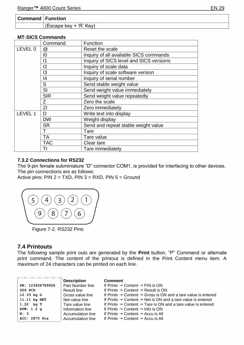
7.3.2 Connections for RS232
The 9-pin female subminiature “D” connector COM1, is provided for interfacing to other devices. The pin connections are as follows: Active pins: PIN 2 = TXD, PIN 3 = RXD, PIN 5 = Ground
Figure 7-2. RS232 Pins
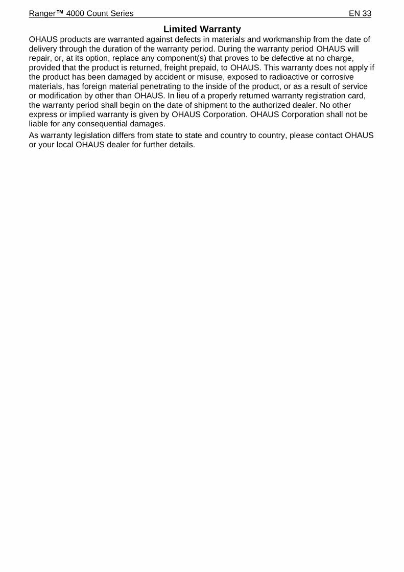
7.4 Printouts The following sample print outs are generated by the Print button, “P” Command or alternate print command. The content of the printout is defined in the Print Content menu item. A maximum of 24 characters can be printed on each line.
Description Comment PN: 123456789926 Part Number line If Printx Content P/N is ON 926 PCS Result line If Printx Content Result is ON 12.33 kg G Gross value line If Printx Content Gross is ON and a tare value is entered 11.11 kg NET Net value line If Printx Content Net is ON and a tare value is entered 1.22 kg T Tare value line If Printx Content Tare is ON and a tare value is entered APW: 1.2 g Information line If Printx Content Info is ON N: 3 Accumulation line If Printx Content Accu is All ACC: 2875 Pcs Accumulation line If Printx Content Accu is All

EN 30 Ranger™ 4000 Count Series
7.5 Output Format Weight string print format:
Field Weight space Unit space Stability space G/N Space Term.
Char(s)
Length 9 1 5 1 1 1 NET 1
Each field is followed by a single delimiting space (ASCII: 32)
Definitions:
Weight - Up to 9 characters, right justified, - at immediate left of most significant character
(if negative).
Unit - Up to 5 characters, left justified. If the Unit in the Print Content menu was set to
OFF, the unit will be removed in the weight string and replaced by spaces.
Stability - “?” character is printed if not stable. If weight is stable neither “?” or following
space is printed.
G/N - “NET” printed if weight is net weight, ‘G’ or nothing printed if weight is a gross
weight.
Terminating Character(s) - terminating character(s) printed depending on FEED menu setting.

Ranger™ 4000 Count Series EN 31
7.6 Compliance Compliance to the following standards is indicated by the corresponding mark on the product.
Mark Standard
This product conforms to the EMC Directive 2004/108/EC, the Low Voltage Directive 2006/95/EC and the Non-Automatic Weighing Instrument Directive 2009/23/EC. The Declaration of Conformity is available online at http://europe.ohaus.com/europe/en/home/support/compliance.aspx
AS/NZS CISPR 11
UL Std. No. 60950-1 (2nd edition) CAN/CSA-C22.2 No. 61010-1-04
Important notice for verified weighing instruments
Weighing Instruments verified at the place of manufacture bear one of the preceding marks on the packing label and the green ‘M’ (metrology) sticker on the descriptive data plate. They may be put into service immediately. Weighing Instruments to be verified in two stages have no green ‘M’ (metrology) on the descriptive data plate and bear one of the preceding identification marks on the packing label. The second stage of the initial verification must be carried out by an authorized and certified service organization established within the European Community or by the National Notified Body.
The first stage of the initial verification has been carried out at the manufacturers work. It comprises all tests according to the adopted European standard EN 45501:1992, paragraph 8.2.2. If national regulations limit the validity period of the verification, the user of the weighing instrument must strictly observe the re-verification period and inform the respective weights and measures authorities.
FCC Note
This equipment has been tested and found to comply with the limits for a Class B digital device, pursuant to Part 15 of the FCC Rules. These limits are designed to provide reasonable protection against harmful interference when the equipment is operated in a commercial environment. This equipment generates, uses, and can radiate radio frequency energy and, if not installed and used in accordance with the instruction manual, may cause harmful interference to radio communications. Operation of this equipment in a residential area is likely to cause harmful interference in which case the user will be required to correct the interference at his own expense.
Industry Canada Note This Class B digital apparatus complies with Canadian ICES-003. ISO 9001 Registration
In 1994, OHAUS Corporation, USA, was awarded a certificate of registration to ISO 9001 by Bureau Veritus Quality International (BVQI), confirming that the OHAUS quality management system is compliant with the ISO 9001 standard’s requirements. On June 21, 2012, OHAUS Corporation, USA, was re-registered to the ISO 9001:2008 standard.

EN 32 Ranger™ 4000 Count Series
Disposal
In conformance with the European Directive 2002/96/EC on Waste Electrical and Electronic Equipment (WEEE) this device may not be disposed of in domestic waste. This also applies to countries outside the EU, per their specific requirements. The Batteries Directive 2006/66/EC introduces new requirements from September 2008 on removability of batteries from waste equipment in EU Member States. To comply with this Directive, this device has been designed for safe removal of the batteries at end-of-life by a waste treatment facility.
Please dispose of this product in accordance with local regulations at the collecting point specified for electrical and electronic equipment. If you have any questions, please contact the responsible authority or the distributor from which you purchased this device.
Should this device be passed on to other parties (for private or professional use), the content of this regulation must also be related.
Disposal instructions in Europe are available online at http://europe.ohaus.com/europe/en/home/support/weee.aspx.
Thank you for your contribution to environmental protection.
Ranger™ 4000 Count Series EN 33
Limited Warranty OHAUS products are warranted against defects in materials and workmanship from the date of delivery through the duration of the warranty period. During the warranty period OHAUS will repair, or, at its option, replace any component(s) that proves to be defective at no charge, provided that the product is returned, freight prepaid, to OHAUS. This warranty does not apply if the product has been damaged by accident or misuse, exposed to radioactive or corrosive materials, has foreign material penetrating to the inside of the product, or as a result of service or modification by other than OHAUS. In lieu of a properly returned warranty registration card, the warranty period shall begin on the date of shipment to the authorized dealer. No other express or implied warranty is given by OHAUS Corporation. OHAUS Corporation shall not be liable for any consequential damages.
As warranty legislation differs from state to state and country to country, please contact OHAUS or your local OHAUS dealer for further details.

EN 34 Ranger™ 4000 Count Series
OHAUS Corporation 7 Campus Drive Suite 310 Parsippany, NJ 07054 USA Tel: +1 973 377 9000 Fax: +1 973 944 7177 With offices worldwide / Con oficinas alrededor del mundo / Avec des bureaux dans le monde entier / Weltweite Geshäftsstellen / Con uffici in tutto il mondo. www.ohaus.com
*30037454* P/N 30037454A © 2015 OHAUS Corporation, all rights reserved / todos los derechos reservados / tous droits réservés / Alle Rechte vorbehalten / tutti i diritti riservati. Printed in China / Impreso en la China / Imprimé en Chine / Gedruckt in China / Stampato in Cina