ramfire burners - techrite controls australia pty · pdf fileall ramfire® burners can be...
TRANSCRIPT
Bulletin 4300
RAMFIRE® Burners
• Improve your furnace temperature uniformity and work penetration with rapid circulation
from RAMFIRE® Burner’s high exit velocities, up to 550 ft/sec (375 MPH)
• Increase furnace loading and reduce flame impingement potential with RAMFIRE® Burner’sshort flame length. Let the high velocity stream of hot combustion gases stir-up your furnace’s heat.
• Maintenance and/or field inspection is simple with burner’s removable backplate, giving direct andeasy access to the gas nozzle and refractory block
• 20:1 turndown capability promotes faster bring-up times without temperature override
• Operate “on-ratio” or with “excess air” to meet specific demands of your process requirements
• Clean burning with natural or propane gases to produce lower NOX levels
• Requires low pressure combustion air for heat releases up to 800,000 Btu/hr in two popular sizes
for maximum cost effectiveness
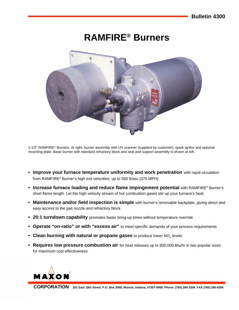
1-1/2" RAMFIRE® Burners: At right, burner assembly with UV scanner (supplied by customer), spark ignitor and optionalmounting plate. Basic burner with standard refractory block and seal and support assembly is shown at left.
CORPORATION 201 East 18th Street, P.O. Box 2068, Muncie, Indiana, 47307-0068. Phone: (765) 284-3304. FAX (765) 286-8394
Page 4302
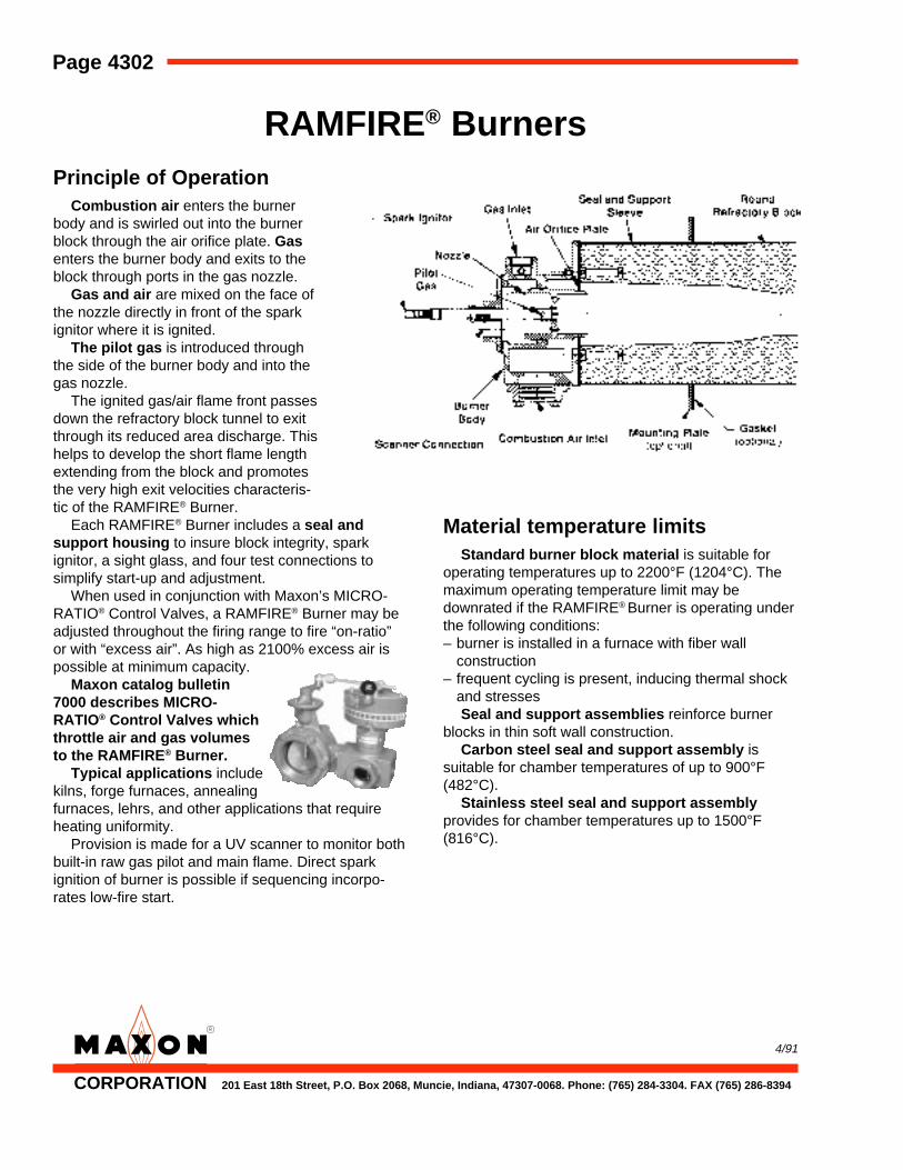
RAMFIRE® BurnersPrinciple of Operation
Combustion air enters the burnerbody and is swirled out into the burnerblock through the air orifice plate. Gasenters the burner body and exits to theblock through ports in the gas nozzle.
Gas and air are mixed on the face ofthe nozzle directly in front of the sparkignitor where it is ignited.
The pilot gas is introduced throughthe side of the burner body and into thegas nozzle.
The ignited gas/air flame front passesdown the refractory block tunnel to exitthrough its reduced area discharge. Thishelps to develop the short flame lengthextending from the block and promotesthe very high exit velocities characteris-tic of the RAMFIRE® Burner.
Each RAMFIRE® Burner includes a seal andsupport housing to insure block integrity, sparkignitor, a sight glass, and four test connections tosimplify start-up and adjustment.
When used in conjunction with Maxon’s MICRO-RATIO® Control Valves, a RAMFIRE® Burner may beadjusted throughout the firing range to fire “on-ratio”or with “excess air”. As high as 2100% excess air ispossible at minimum capacity.
Maxon catalog bulletin7000 describes MICRO-RATIO® Control Valves whichthrottle air and gas volumesto the RAMFIRE® Burner.
Typical applications includekilns, forge furnaces, annealingfurnaces, lehrs, and other applications that requireheating uniformity.
Provision is made for a UV scanner to monitor bothbuilt-in raw gas pilot and main flame. Direct sparkignition of burner is possible if sequencing incorpo-rates low-fire start.
4/91
Material temperature limitsStandard burner block material is suitable for
operating temperatures up to 2200°F (1204°C). Themaximum operating temperature limit may bedownrated if the RAMFIRE® Burner is operating underthe following conditions:– burner is installed in a furnace with fiber wall
construction– frequent cycling is present, inducing thermal shock
and stressesSeal and support assemblies reinforce burner
blocks in thin soft wall construction.Carbon steel seal and support assembly is
suitable for chamber temperatures of up to 900°F(482°C).
Stainless steel seal and support assemblyprovides for chamber temperatures up to 1500°F(816°C).
CORPORATION 201 East 18th Street, P.O. Box 2068, Muncie, Indiana, 47307-0068. Phone: (765) 284-3304. FAX (765) 286-8394

RAMFIRE® Burners Page 4303
9/93
Capacity/Selection Data
All RAMFIRE® Burners can be fired “on-ratio” orwith “excess air”. They include built-in test portconnections for simplified start-up and adjustments, aspark ignitor and a gas pilot.
Performance data is provided in table below.Gas pilot requires separately regulated natural gas
differential pressure of 5-6" wc to the inlet of (optional)pilot gas adjustable orifice.
Cataloged minimums require an air differential of0.1" wc for 1-1/2" burner size and 0.2" wc for 2"burners. This translates to 35% excess air for the1-1/2" burner and 75% for the 2" at rated minimum. Ifon-ratio minimum is required, output will be consider-ably higher.
Performance limits show the maximum “excessair” ratio possible at minimum firing rate.
Fuel supply differential pressures (read betweenG
1 test connection and combustion chamber) are
shown for natural gas. To achieve cataloged maxi-mum, natural gas must be supplied at 10 osi (18" wc)at the burner inlet.
Maximum capacity is a function of differential airpressure to the burner air inlet connections as readbetween A
1 test connection and combustion chamber.
Combustion air must be available at 15 osi at theburner inlet. Combustion air blower rating should beat least 2 ounces higher than burner air inlet require-ments to allow for manifolding pressure losses.
Combustion air flows show two figures: the first isthe flow (in SCFM) required at maximum ratedcapacity. The second set of numbers, denoted “forsizing”, indicates the actual flow rate that will beencountered in starting up a “cold” burner. If combus-tion blower is to be used to purge combustion cham-ber, blower must be sized for the larger air volumes toprevent possible blower motor overloading. The lowerfigure at maximum rated capacity is the result of backpressure developed within the burner while firing.
Flame geometry is also shown in the table below.Flame remains within the burner’s refractory block atmost firing rates. The flame length shown is mea-sured from the end of burner block at maximum ratedcapacity. The diameter shown is the greatest that maybe expected over entire capacity range.
srotcaFecnamrofreP
ERIFMAR"G"seireS ® eziSrenruB "5.1 "2
rianoitsubmocderiuqeRserusserplaitnereffidseiticapacmumixamrof
dnatelnirenrubneewtebderusaemnoitidnoccitatsrebmahc
.c.wsehcni62)iso51(
tsetriarenrubssorcaderusaemAsnoitcennoc 1 Adna 2
.c.wsehcni21)iso9.6(
saglarutanderiuqeRerusserplaitnereffidyticapacmumixamrof
dnatelnirenrubneewtebderusaemnoitidnoccitatsrebmahc
.c.wsehcni81)iso4.01(
tsetsagrenrubssorcaderusaemGsnoitcennoc 1 Gdna 2
.c.wsehcni9)iso2.5(
seiticapaC)rh/utB(
mumixaM 000,004 000,008
muminim/tolip"oitar-nO" 000,04 000,021
htiwmuminim/toliP )tnecrep( riassecxe000,02)%53(
000,05)%57(
htiwstimilecnamrofreP)iso51mumixam(
rianoitsubmoc
renrubthgilotyticapacmuminiM )rh/utB( 000,02 000,05
riassecxetnecreP %0012 %0661
oitarnwodnruT 1:02 1:61
emulovrianoitsubmoC ]1[yticapacmumixamrofderiuqer
yticapacmumixamrofderiuqerMFCS 76 431
gnizisrewolbrofderiuqerMFCS 08 061
yrtemoegemalFhtgneL )sehcni( "41 "02
retemaiD )sehcni( "2 "3
"swolfrianoitsubmoc"gnidrageregapfopottanoitanalpxeetoN]1[
Gas check valves should behorizontally installed in multi-burner applications as close aspossible to each burner inlet fordependable light-off (gas mani-fold may otherwise act as areservoir, preventing light-offduring trial-for-ignition period).
Air and gas balancing valvesmay be used on multi-burnerinstallations for improved heatinguniformity.
Page 4304 RAMFIRE® Burners
Accessory Options
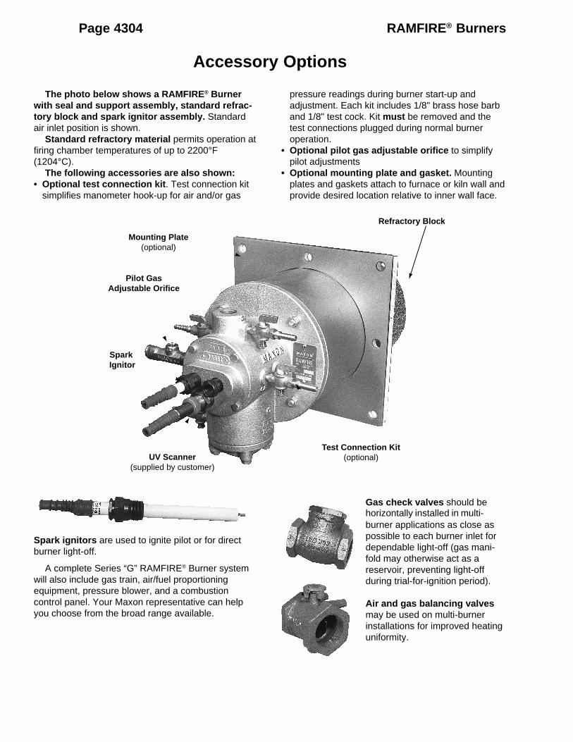
The photo below shows a RAMFIRE® Burnerwith seal and support assembly, standard refrac-tory block and spark ignitor assembly. Standardair inlet position is shown.
Standard refractory material permits operation atfiring chamber temperatures of up to 2200°F(1204°C).
The following accessories are also shown:• Optional test connection kit. Test connection kit
simplifies manometer hook-up for air and/or gas
pressure readings during burner start-up andadjustment. Each kit includes 1/8" brass hose barband 1/8" test cock. Kit must be removed and thetest connections plugged during normal burneroperation.
• Optional pilot gas adjustable orifice to simplifypilot adjustments
• Optional mounting plate and gasket. Mountingplates and gaskets attach to furnace or kiln wall andprovide desired location relative to inner wall face.
Spark ignitors are used to ignite pilot or for directburner light-off.
A complete Series “G” RAMFIRE® Burner systemwill also include gas train, air/fuel proportioningequipment, pressure blower, and a combustioncontrol panel. Your Maxon representative can helpyou choose from the broad range available.
Refractory Block
Test Connection Kit(optional)UV Scanner
(supplied by customer)
Spark Ignitor
Pilot GasAdjustable Orifice
Mounting Plate(optional)
RAMFIRE® Burners Page 4305
10/92
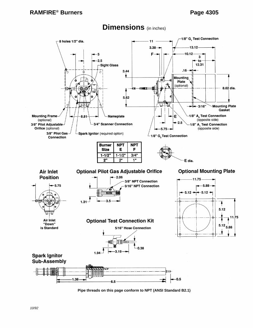
Dimensions (in inches)
Pipe threads on this page conform to NPT (ANSI Standard B2.1)

Page 4306 RAMFIRE® Burners
Component Identification
To order replacement parts:1. Specify parts by the names shown in the sketch
above2. Indicate quantity desired3. Indicate burner size from numbers cast on side of
nozzle body and/or pipe size of air inlet connection4. If ordering refractory block sub-assemblies, identify
refractory material code stamped on block framebolt heads
Nameplate
�CORPORATIONMUNCIE, INDIANA, USAINDUSTRIAL COMBUSTION EQUIPMENT AND VALVES
Maxon practices a policy of continuous product improvement. It reserves the right to alter specifications without prior notice.2/95
RAMFIRE® Burners Page 4300-S-1
Installation and Maintenance Instructions
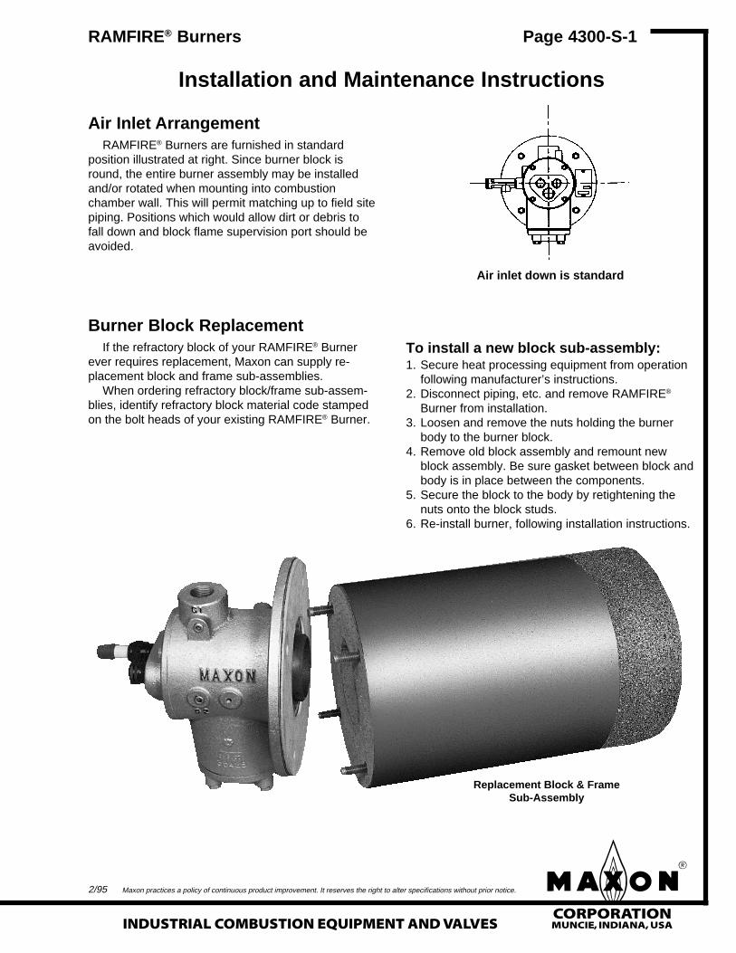
Air Inlet ArrangementRAMFIRE® Burners are furnished in standard
position illustrated at right. Since burner block isround, the entire burner assembly may be installedand/or rotated when mounting into combustionchamber wall. This will permit matching up to field sitepiping. Positions which would allow dirt or debris tofall down and block flame supervision port should beavoided.
Burner Block ReplacementIf the refractory block of your RAMFIRE® Burner
ever requires replacement, Maxon can supply re-placement block and frame sub-assemblies.
When ordering refractory block/frame sub-assem-blies, identify refractory block material code stampedon the bolt heads of your existing RAMFIRE® Burner.
To install a new block sub-assembly:1. Secure heat processing equipment from operation
following manufacturer’s instructions.2. Disconnect piping, etc. and remove RAMFIRE®
Burner from installation.3. Loosen and remove the nuts holding the burner
body to the burner block.4. Remove old block assembly and remount new
block assembly. Be sure gasket between block andbody is in place between the components.
5. Secure the block to the body by retightening thenuts onto the block studs.
6. Re-install burner, following installation instructions.
Air inlet down is standard
Replacement Block & FrameSub-Assembly
�CORPORATIONMUNCIE, INDIANA, USA INDUSTRIAL COMBUSTION EQUIPMENT AND VALVES
Maxon practices a policy of continuous product improvement. It reserves the right to alter specifications without prior notice.
Page 4300-S-2 RAMFIRE® Burners
Installation Instructions
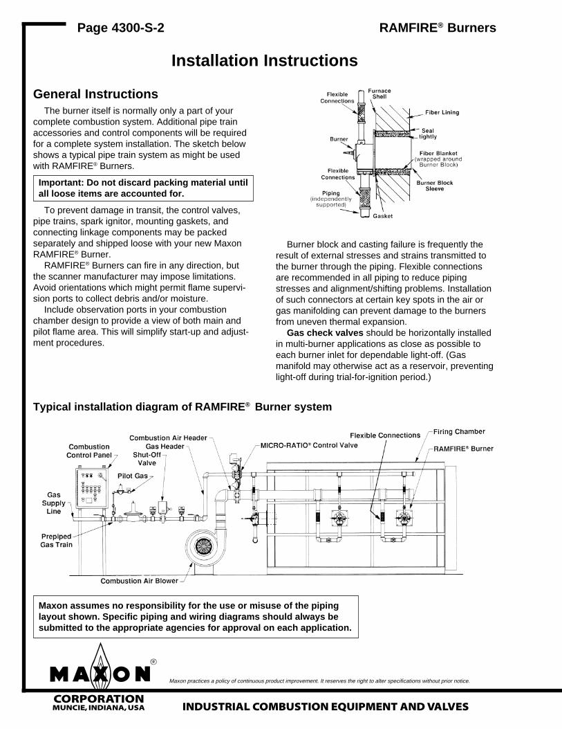
General InstructionsThe burner itself is normally only a part of your
complete combustion system. Additional pipe trainaccessories and control components will be requiredfor a complete system installation. The sketch belowshows a typical pipe train system as might be usedwith RAMFIRE® Burners.
Important: Do not discard packing material untilall loose items are accounted for.
To prevent damage in transit, the control valves,pipe trains, spark ignitor, mounting gaskets, andconnecting linkage components may be packedseparately and shipped loose with your new MaxonRAMFIRE® Burner.
RAMFIRE® Burners can fire in any direction, butthe scanner manufacturer may impose limitations.Avoid orientations which might permit flame supervi-sion ports to collect debris and/or moisture.
Include observation ports in your combustionchamber design to provide a view of both main andpilot flame area. This will simplify start-up and adjust-ment procedures.
Burner block and casting failure is frequently theresult of external stresses and strains transmitted tothe burner through the piping. Flexible connectionsare recommended in all piping to reduce pipingstresses and alignment/shifting problems. Installationof such connectors at certain key spots in the air orgas manifolding can prevent damage to the burnersfrom uneven thermal expansion.
Gas check valves should be horizontally installedin multi-burner applications as close as possible toeach burner inlet for dependable light-off. (Gasmanifold may otherwise act as a reservoir, preventinglight-off during trial-for-ignition period.)
Typical installation diagram of RAMFIRE® Burner system
Maxon assumes no responsibility for the use or misuse of the pipinglayout shown. Specific piping and wiring diagrams should always besubmitted to the appropriate agencies for approval on each application.

�CORPORATIONMUNCIE, INDIANA, USAINDUSTRIAL COMBUSTION EQUIPMENT AND VALVES
Maxon practices a policy of continuous product improvement. It reserves the right to alter specifications without prior notice.5/94
RAMFIRE® Burners Page 4300-S-3
Installation Instructions (continued)
RAMFIRE® Burner requires a separate combus-tion air blower. The nozzle mixing burners serve astheir own fuel/air mixing device.
The blower should not be exposed to direct radiantheat or positioned where it might draw in inert gases.If problems exist, consider relocation.
Electrical service must match the voltage, phaseand cycle of all electrical system components and becompatible with burner nameplate ratings. Insure thatall normal control safeguards are satisfied. Combus-tion air blower should continue to run after shutdownto allow burner to cool.
Gas supply piping must be large enough tomaintain the required fuel pressures cataloged for theparticular burner size used with burner operating atfull-rated capacity.
Anything more than minimal distance or pipingturns may necessitate oversizing piping runs to keeppressure drops within acceptable ranges.
If multiple burners are fed from a single gas train,care should be taken to minimize pressure drop andgive maximum uniformity.
Clean fuel lines are essential to prevent blockageof pipe train components or burner gas ports.
Main shut-off cock should be upstream of boththe main gas regulator and pilot line take-off. Use it toshut off fuel to both pilot and main burner during shut-down periods of more than a few hours.
The fuel throttling MICRO-RATIO® Valve with aMaxon RAMFIRE® Burner is not intended for tightshut-off.
Main gas regulator is essential to maintain auniform system supply pressure. If one pipe trainsupplies multiple burners, provide a separate regula-tor in the branch leading to each burner system.
Size the regulator for full system capacity at therequired pressure, carefully considering pipe trainlosses. Follow the instructions attached to the regula-tor during installation.
Pilot take-off should be upstream of the main gasregulator, but downstream of the main gas cock. Itshould normally include its own pilot gas regulator, asolenoid valve, and shut-off cock. A pilot adjustableorifice at the pilot inlet simplifies adjustment.
Pilot piping must be large enough to provide forthe full flow and pressures shown in the catalog foryour particular burner size.
Fuel shut-off valves (when properly connected toa control system) are designed to shut the fuel supplyoff with a loss of electrical power. Manual resetvalves require operator attendance each time thesystem is started up (or restarted after a shut-down).
Motorized shut-off valves permit automatic start-restart when used with an appropriate control system.
Test connections are essential for burner adjust-ment. They should be provided immediately upstreamof the burner and are included in the burner itself.Test connections must be plugged except whenreadings are being taken.
Blower location must deliver a reasonably cleanand cool air supply. Care must be taken to keep airmanifold pressure drops to a minimum and to inde-pendently support the weight of air piping.
Gas and air piping should be located reasonablyclose to the burner and sized for the pressure andvolume requirements of the burner, with supplypressures high enough to permit subsequent regula-tion at each burner. Gas piping drops should notexceed 10% of initial supply pressure.
Control systems should provide all normallyrecommended interlocks (including operation of fuelshut-off valves). Sequencing control systems areavailable from Maxon that include provision for post-purge pilots during all but emergency shut-downs.
Control system’s circuitry must not allow mainfuel shut-off valve to be opened unless combustion airis on, and must de-energize valve upon loss ofcombustion air pressure, along with the other usualsystem interlocks. Motor starter is to be interlockedwith valve, along with a combustion air pressureswitch.
Flame sensing is accomplished by UV scanner.UV scanner should be kept as close to burner asfeasible. Heat block, if used, may affect signalstrength with some brands of scanners.
Low fire start and interrupted pilot are essential toobtain cataloged minimums.
Burner and pipe manifold support will be re-quired to support weight of the burner and anyconnected pipe train components. Air control motors,in particular, require additional support. Maxonconnecting base and linkage assemblies are de-signed to position the control motors to work with thecontrol valve, not to support their weight.
Multi-burner installations require special consid-erations if supplied by a common pipe train and/or airsupply. Air and Gas Balancing Valves should beused for improved heating uniformity; Gas SwingCheck Valves may be installed in horizontal pipe andas close as possible to each burner inlet for depend-able light-off (gas manifold may otherwise act as areservoir, preventing light-off during trial-for-ignitionperiod).
�CORPORATIONMUNCIE, INDIANA, USA INDUSTRIAL COMBUSTION EQUIPMENT AND VALVES
Maxon practices a policy of continuous product improvement. It reserves the right to alter specifications without prior notice.
Page 4300-S-4 RAMFIRE® Burners
Installation Instructions (continued)
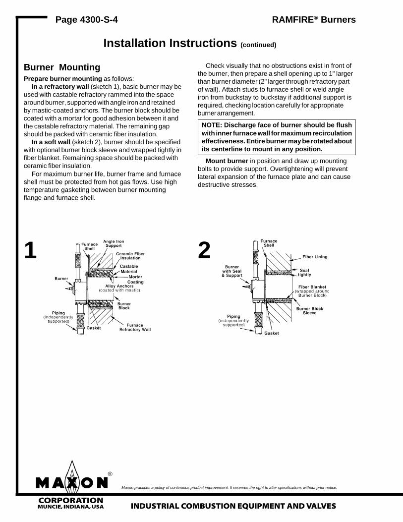
Burner MountingPrepare burner mounting as follows:
In a refractory wall (sketch 1), basic burner may beused with castable refractory rammed into the spacearound burner, supported with angle iron and retainedby mastic-coated anchors. The burner block should becoated with a mortar for good adhesion between it andthe castable refractory material. The remaining gapshould be packed with ceramic fiber insulation.
In a soft wall (sketch 2), burner should be specifiedwith optional burner block sleeve and wrapped tightly infiber blanket. Remaining space should be packed withceramic fiber insulation.
For maximum burner life, burner frame and furnaceshell must be protected from hot gas flows. Use hightemperature gasketing between burner mountingflange and furnace shell.
Check visually that no obstructions exist in front ofthe burner, then prepare a shell opening up to 1" largerthan burner diameter (2" larger through refractory partof wall). Attach studs to furnace shell or weld angleiron from buckstay to buckstay if additional support isrequired, checking location carefully for appropriateburner arrangement.
NOTE: Discharge face of burner should be flushwith inner furnace wall for maximum recirculationeffectiveness. Entire burner may be rotated aboutits centerline to mount in any position.
Mount burner in position and draw up mountingbolts to provide support. Overtightening will preventlateral expansion of the furnace plate and can causedestructive stresses.
1 2

�CORPORATIONMUNCIE, INDIANA, USAINDUSTRIAL COMBUSTION EQUIPMENT AND VALVES
Maxon practices a policy of continuous product improvement. It reserves the right to alter specifications without prior notice.
RAMFIRE® Burners Page 4300-S-5
Start-Up Instructions
4/91
Read complete instructions before proceeding,and familiarize yourself with all the system’s equip-ment components. Verify that your equipment hasbeen installed in accordance with the originalmanufacturer’s current instructions.
CAUTION: Initial adjustment and light-offshould be undertaken only by trained andexperienced personnel familiar with combus-tion systems, with control/safety circuitry, andwith knowledge of the overall installation.Instructions provided by the company and/orindividuals responsible for the manufactureand/or overall installation of complete systemincorporating Maxon burner take precedenceover these provided by Maxon. If Maxon in-structions conflict with any codes or regula-tions, contact Maxon Corporation beforeattempting start-up.
NOTE: The following instructions assume use ofpiloted burners and Standard Cam MICRO-RATIO®
Valves:The photograph below shows a MICRO-RATIO®
Valve assembly consisting of an air butterfly valve tocontrol combustion air flow and an adjustable-gradiantSYNCHRO gas flow control valve. The latter ismechanically linked to the air valve and a series ofadjusting screws permits setting of a desired air/fuelratio throughout the burner firing range. A pneumaticor electric control motor will normally be mounted tothis MICRO-RATIO®
Valve assembly andestablish firing ratesin accordance withsystem demands.
Additional dataon Maxon MICRO-RATIO® Valves isprovided in catalogbulletin 7000.
For initial system start-up:1. Close all burner fuel valves and/or cocks.
Make preliminary adjustments to regulators.2. Check all electric circuitry. Verify that all safety
devices and interlocks are operable and function-ing within their respective settings/ranges. Besure all manifolds are tight and that test ports areplugged if not being used.
3. Check that all duct and chamber dampers areproperly positioned and locked into operatingpositions.
Vent dampers and pressure controllersshould be used to maintain balanced orslightly positive furnace pressures (0.0" to0.05" wc) for maximum efficiency. Excessiveback pressure can damage furnace and/or reduceburner capacity. Negative pressures allow infiltra-tion of secondary air and can seriously affectefficiency and temperature uniformity.
4. Start all system-related fans and blowers.Check for proper motor rotation and impellerdirection. Verify that all safety interlocks areworking. Allow air handling equipment to run foradequate purge of manifold and combustionchamber plenums.
CAUTION: Do not by-pass control panel timerstypically controlling sequential operations.
5. Initial start-up adjustment should only beaccomplished during a “manual” controlmode.Using a 3/16" allen wrench, disconnect theautomatic control motor’slinkage from MaxonMICRO-RATIO® ControlValve by loosening yourcontrol motor’s connect-ing rod from the valve’stoggle linkage.
Test connections are essential for burner adjust-ment. Each RAMFIRE® Burner includes air and fueltest connections but additional connections should beprovided (at minimum) downstream of the regulatorand MICRO-RATIO® Valve.
Do not attempt to use test connections in pipeelbows or tees, as internal turbulence can giveerroneous readings. Test connections must beplugged except when readings are being taken.
Disconnect thislinkage from
MICRO-RATIO® Valve

�CORPORATIONMUNCIE, INDIANA, USA INDUSTRIAL COMBUSTION EQUIPMENT AND VALVES
Maxon practices a policy of continuous product improvement. It reserves the right to alter specifications without prior notice.
6. Series “G” RAMFIRE® Burners include built-in testconnections both upstream and downstream ofinternal fuel and air orifices. To achieve ratedcapacities, adjust MICRO-RATIO® Control Valveto give the differential pressures indicated oncharts on page 4300-S-9.
Gas differential pressures read acrossburner’s built-in gas test connections G
1 and G
2
(shown in photo below) are shown in Chart 1.Note that natural gas flows are in standard cubicfeet/hour and are gas differential readings acrossburner gas test connections (not inlet gas supply)pressure in inches w.c.
For propane firing, these differential gaspressure readings would be 40% of these indi-cated for the equivalent natural gas heat releases.
Page 4300-S-6 RAMFIRE® Burners
Start-Up Instructions (continued)
Combustion air differential pressures readacross burner’s built-in air test connections A
1 and
A2 (shown in photo above) are shown in Chart 2.
Note that graph for 2" RAMFIRE® begins at 0.2"wc differential. This is required minimum for 2"size.
Maxon offers a “test connection kit” accessorywhich provides a convenient means of connectingplastic tubing to the burner test port connections.Kit should be removed after initial start-up and thetest ports plugged for normal burner operations.
General: To achieve rated capacities, a RAMFIRE®
Burner must be adjusted to give the specific air andgas differential pressures as indicated in the chartsshown on pages 4300-S-9.
7. Set minimum air differential pressure at 0.1" w.c.With MICRO-RATIO® Valve combinations of air
and fuel valves, the minimum differential setting isinitially established with the air valve only.
Disconnect the linkage between the air valveand fuel valve(s) on the MICRO-RATIO® Valveassembly.
Rotate the air valve while watching themanometer for the minimum air differentialpressure of 0.1" wc. (Note: This is a very smallincrement on a normal manometer. Readings/settings above 0.1" wc will lessen turndown ratioof burner system.) Then mark red air valve dial(see sketch below) opposite crank pointer.
8. Establish the maximum combustion airdifferential pressure by moving MICRO-RATIO®
Valve assembly toward the higher numberedpositions until the desired air differential (inaccordance with burner specifications) is reached.Again, mark red air valve dial opposite crankpointer (refer to Chart 2 on page 4300-S-9).
Loosen to separate air valvemovement from fuel valve(s) travel
A1
A2
G1
G2
Test connections areshown with optionaltest connection kits

�CORPORATIONMUNCIE, INDIANA, USAINDUSTRIAL COMBUSTION EQUIPMENT AND VALVES
Maxon practices a policy of continuous product improvement. It reserves the right to alter specifications without prior notice.
For example: A combustion system may need theair valve to only be 15° open for the “minimum”setting and the “maximum” requirements aresatisfied with the air valve open to 60°. By markingthese points on the air valve’s indicating strip, youare ready to reconnect the SYNCHRO Fuel Valve’slinkage to the air valve.
9. Reconnect the SYNCHRO Fuel Valve linkageto the MICRO-RATIO® assembly’s air valve.
Having marked the MICRO-RATIO® air controlvalve’s settings for both minimum and maximumfiring positions, you may adjust the linkage andtravel of the SYNCHRO gas valve’s stroke (seesketch below).
RAMFIRE® Burners Page 4300-S-7
Start-Up Instructions (continued)
Re-tighten binding screw [2] and return theMICRO-RATIO® Valve to the “minimum” airsetting.
This time, loosen set screw [1] and againcorrect for just half of the distance required tomake the air valve pointer indicate the minimum airvalve setting.
Re-tighten set screw [1] and again return theMICRO-RATIO® Valve to its maximum position.
Similarly, correct one half the distance withbinding screw [2] for the maximum setting, etc.
Continue this adjustment procedure untilthe gas and air valves reach their minimumand maximum positions simultaneously.Normally, this is accomplished within sevenadjustments.
10. To prepare Maxon MICRO-RATIO® Valve forinitial fuel firing adjustment:
Remove coverplate from screwcarrier cam assem-bly and turn alladjusting screwscounter-clockwiseuntil flush with outersurface of casting(new equipment isshipped this way).
If multiple fuel arrangement, adjust linkagerods and toggle arrangements betweenSYNCHRO Fuel Control Valve(s) so that all fuelcontrol valves travel together (from minimum tomaximum positions). Leave MICRO-RATIO®
Valve(s) at “minimum” position, as shown bypointer on position indicator strip.
11. To light and adjust gas pilot: Check to insurecombustion air supply is flowing to burner. Pilotgas regulator should initially be set at approxi-mately midpoint of its adjustment range. With pilotgas solenoid closed, open main fuel gas and pilotgas cock. Energize spark ignitor and pilot gassolenoid. Turn pilot gas adjustable orifice screwout (counter-clockwise) several turns from its fullyseated position. Observe ignition of pilot gasthrough sight port of burner assembly and/or byviewing flame signal metered from flame safe-guard relay circuit.
4/91
Loosen Allen set screw [1] and binding screw[2] in toggle [4]. Move the toggle in universal camassembly slot towards the center of rotation sothat gas valve can rotate from its minimum tomaximum position, while the air valve swingsbetween the established (and marked) minimumand maximum settings.
Place air valve on pre-determined “minimum”position and rotate gas valve to its “minimum” set-ting position. Tighten down set screw [1] and bindingscrew [2] with both valves set at “minimum”.
Establish set screw [1] as minimum-endadjustment point and binding screw [2] as maxi-mum-end adjustment point. (Note: It doesn’t matterwhich is maximum or minimum, as long as youidentify and keep the same reference points for thenext adjustment steps.)
Now rotate MICRO-RATIO® Valve to “maxi-mum” position. The air valve maximum settingwas previously determined. Loosen binding screw[2] and adjust pointer and linkage to correct justhalf of the distance required to make the air valvepointer indicate the maximum air valve setting.
Adj. Screws(under cover)
Handle forManual
OperationPositionIndicatorPointer
Locking Screwfor manualoperation

�CORPORATIONMUNCIE, INDIANA, USA INDUSTRIAL COMBUSTION EQUIPMENT AND VALVES
Maxon practices a policy of continuous product improvement. It reserves the right to alter specifications without prior notice.
Refine pilot gas setting for a hard blue flame(and/or strongest flame signal) by adjusting gasflow through pilot orifice and/or pilot regulator.
Shut off pilot gas cock to extinguish pilot fire.Reopen and confirm easy re-ignition severaltimes. The flame safeguard relays should nowpower the main fuel shut-off valves.
Verify all safety interlocks are operational beforeopening any main and/or individual burner valves.
12. To light and adjust RAMFIRE® Burner on gas:With gas pilot established and flame supervisionsystem operational, opening the main fuel shut-offvalve(s) will allow fuel flow to the SYNCHRO FuelControl Valve of MICRO-RATIO® Valve assembly.
13. Turn minimum adjusting screw in (clockwise)to open gas valve until gas is ignited at burners.Several turns of the screw may be necessary.Flame should normally be confined back in theburner block at rated minimums. (Higher mini-mums might possibly extend flames beyondburner block.)
NOTE: At this point, it is more important to get any kindof a flame as soon as possible. The flame geometry canbe adjusted and refined as needed later.14. Adjust main gas regulator (as necessary to
maintain required burner differential). Re-adjustminimum screw if necessary.
If pilots are to be interrupted, shut them off at thispoint and verify that main flame remains lit and holdsin flame detectors. Re-adjust if necessary.
15. Once your flame is established and refined atthis position, and without advancing the screwcarrier quadrant higher, screw all remainingscrews down to at least the same level as yourfirst adjusted screw.
NOTE: A preliminary setting can be established with allthe remaining adjusting screws. Generally, each suc-ceeding screw needs to be screwed in approximatelyone full turn deeper than its preceding screw. A smooth“stair-step” gradient pre-set at this point from low to highwill simplify the remaining adjustment steps.16. With allen wrench engaged in second screw,
slowly move MICRO-RATIO® Valve to #1position, adjusting as necessary to maintainignition and the type of flame desired. Flamelength should increase slightly, burning with ablue center and yellow tips, and a steady combus-tion noise.
Page 4300-S-8 RAMFIRE® Burners
Start-Up Instructions (continued)
If firing into an uncured refractory chamber,allow system to run at this setting for thedryout period recommended by the furnace orrefractory manufacturer, then continue adjust-ment of the MICRO-RATIO® Valve.
17. Turn all remaining adjustment screws inslightly further than the second screw, thenwith allen wrench inserted in third screw, slowlymove MICRO-RATIO® Valve toward #2 position,adjusting as necessary.
CAUTION: If flame is extinguished, immediatelyshut off gas and return MICRO-RATIO® Valve tominimum position. Verify that pilots are stillburning then reopen gas valve and turn screwlast adjusted in slightly further before returningto that firing position. Refine adjustment ifnecessary.
18. Progressively work your way up through eachadjusting screw position, developing a smoothprogression slope from your first screw to the“maximum” position.
NOTE: To adjust the flame at any position, you mustmove the SYNCHRO Valve to the number you desireto adjust. This aligns the adjusting screw directly ontop of the fuel valve plunger. A resulting adjustment ofthe screw is directly applied to the fuel valve plungerand its interconnected valve body linkage.
If high temperature limit trips before adjust-ment is completed, cycle back to minimum andhold there until the system cools down beforeattempting further adjustment.
19. Note gas supply pressure while continuingwith adjustment. If it falls off below acceptablerange, it may be necessary to re-adjust theregulator. If so, lower firing positions will needrechecked and if necessary, re-adjusted beforeproceeding.
20. When all screws have been adjusted, recheckdifferential pressures with unit at operatingtemperature. Refine “high fire” setting if neces-sary, considering differential pressure, flamelength, and appearance.
Flame should be blue with yellow tails andwith a steady combustion noise. Dust or contami-nants in the air stream may affect flame appear-ance.

�CORPORATIONMUNCIE, INDIANA, USAINDUSTRIAL COMBUSTION EQUIPMENT AND VALVES
Maxon practices a policy of continuous product improvement. It reserves the right to alter specifications without prior notice.
RAMFIRE® Burners Page 4300-S-9
Start-Up Instructions (continued)
6/91
Chart 1The charts at right show specific differentialgas (Chart 1) and air (Chart 2) pressure readingsat various firing rates. This data may be used torefine your RAMFIRE® Burner adjustments.
21. If system will operate with interrupted pilot(considered good practice), shut pilots off nowand cycle MICRO-RATIO® Valve slowly fromminimum to maximum and back, with all convec-tion system dampers in operating position or withfurnace door closed.
22. When burner performance is satisfactory andstable throughout the firing range, reconnectlinkage from control motor to MICRO-RATIO®
Valve.23. Check out overall system operation on all fuels
by cycling through light-off at minimum, interrupt-ing pilot, and allowing temperature control systemto cycle burner from minimum to maximum andreturn. Recheck all safety system interlocks forproper setting and operation.
CAUTION: Test every UV installation for dan-gerous spark excitation from ignitors, and otherburners, direct or reflected UV radiation.
24. Shut system down, closing all fuel valves andallowing an approved post-purge period beforeshutting down fans and combustion air blower.Remove test connections and plug openings, thenreplace all equipment covers and caps andtighten all linkage set screws.
25. Instruct operator on proper start-up, operationand shutdown of system. Establish writteninstructions for reference.
Chart 2
�CORPORATIONMUNCIE, INDIANA, USA INDUSTRIAL COMBUSTION EQUIPMENT AND VALVES
Maxon practices a policy of continuous product improvement. It reserves the right to alter specifications without prior notice.
Page 4300-S-10 RAMFIRE® Burners
Notes