railways track characterization using ground penetrating … · settlements and transitions...
TRANSCRIPT
doi: 10.1016/j.proeng.2016.06.120
Railways Track Characterization Using Ground Penetrating Radar
Simona Fontul1*, Eduardo Fortunato1, Francesca De Chiara2, Rui Burrinha3
and Marco Baldeiras3
1National Laboratory for Civil Engineering (LNEC), Portugal 2Sapienza University of Rome, Italy
2Infraestruturas de Portugal, Portugal
[email protected], [email protected], [email protected], [email protected], [email protected]
AbstractA proper quality control of the railway track condition and its monitoring since the construction phase are key factors for a long life cycle and for an efficient maintenance policy. For this purpose, suitable techniques, such as non-destructive tests, represent an efficient monitoring solution as they allow evaluating infrastructure characteristics continuously, saving time and costs, with minimal interferences on track use. Ground Penetrating Radar (GPR) is a fast and effective electromagnetic survey technique that enables the measuring of layers thickness, detection of changes on structure or on materials properties along the line. It can also detect different types of defects such as ballast pockets, fouled ballast, poor drainage, subgrade settlement and transitions problems, depending on their extension. These defects are generally the causes of vertical deviations in track geometry and they cannot be detected by the common monitoring procedures, namely the measurements of track geometry. GPR application to railways infrastructures at network level is relatively recent. In Portugal, rail inspection is performed with Plasser & Theurer EM120 equipment and recently 400 MHz IDS antennas were installed on it. GPR tests were performed on the Portuguese rail network and, as case study, a section of an in service tracks is addressed in this paper. A combined monitoring approach is presented, based on interpretation of the geometric parameter measurement, currently utilized for maintenance planning, together with GPR results, in order to detect the causes of the track deterioration and to plan more appropriate maintenance interventions.
Keywords: Ground Penetrating Radar; track maintenance, inspection vehicle, dielectric constants, geometric parameters
* Corresponding author
Procedia Engineering
Volume 143, 2016, Pages 1193–1200
Advances in Transportation Geotechnics 3 . The 3rdInternational Conference on Transportation Geotechnics
(ICTG 2016)
Selection and peer-review under responsibility of the Scientific Programme Committee of ICTG 2016c© The Authors. Published by Elsevier B.V.
1193
1 Introduction
As all types of infrastructures, railways have to present adequate behaviour during their entire life cycle. During the railway infrastructures operation, some track components have to be replaced while others can remain the same, in particular the substructure (Berggren, 2009; Esveld, 2001).
An adequate maintenance policy, that guarantee high safety standards, has to be established (Sussmann et al., 2001; Saaranketo, 2006) and, at the same time, costs of maintenance and duration of traffic interruptions have to be limited.
Presently, two crucial aspects have to be taken into account. On one hand, the increase of traffic speeds and axle loads on existing structures, initially designed for lower speeds and loads. On the other hand, the climatic changes are important factors that can damage the structure, due to intense precipitation or higher temperatures. These lead to faster track deterioration, and, consequently, to a poorer performance and lower service quality.
Nowadays, the track monitoring consists in assessing mainly parameters related to the track geometry and rail wearing. This monitoring procedure does not detect the real causes of deficiency, which can be generated by the presence of ballast pockets, fouled ballast, poor drainage, subgrade settlements and transitions problems (Manacorda et al., 2002; Fontul et al., 2011; Hyslip et al., 2012). Therefore, an important factor for maintenance decision is the substructure condition assessment (Fortunato et al., 2010).
In order to perform an efficient railway assessment, non-destructive tests represent a proper monitoring tool (Fontul, 2004; Loizos et al., 2007; Fontul et al., 2011). Equipment, such as Ground Penetrating Radar (GPR), can be used for railway condition evaluation in terms of layers geometry and fouling level assessment.
In the last years, many studies were focused on ballast thicknesses measurements and its quality characterisation, namely fouling analysis, based on new GPR signals processing and interpretation (Clark et al., 2004; Forde et al., 2010; Manacorda and Simi, 2012; Al-Qadi et al., 2010; Roberts et al., 2006; Shangguan et al., 2012; Shao et al., 2011; Silvast et al., 2006; Zhang et al., 2011; De Chiara et al., 2014).
In this paper, a new procedure of combining traditional track characterization of existing lines, namely the geometric level, with GPR monitoring is presented. A particular attention was dedicated to track degradation and its possible causes, trying to identify patterns on the GPR measurements and on the geometric level evolution that can support a better maintenance policy. A case study is presented to exemplify the feasibility of this approach for maintenance interventions decisions.
2 Railway Inspection and Maintenance
2.1 Inspection Methodology For a better and faster railway characterisation during monitoring phase, equipment has been
developed in the last years, aiming to evaluate one or more parameters at the same time. Today monitoring actions are usually performed by using track inspection vehicles, as they can
reach speeds between 30 and 300 km/h, enabling an efficient track characterisation at network level. A detailed description of these equipment can be found in Esveld (2001) and Lichtberger (2005).
Inspection vehicles enable the evaluation of track performance and the detection of geometric defects. They present the main advantage of working at similar speeds and dynamic loads of regular trains, allowing to the track performance assessment in a more realistic way, compared with other methods, such as the manual ones. Moreover, they allow recording measurements, of the longitudinal profile and the cross sections, in a continuous way, without traffic interruptions.
Railways Track Characterization using Ground Penetrating Radar Fontul et al.
1194
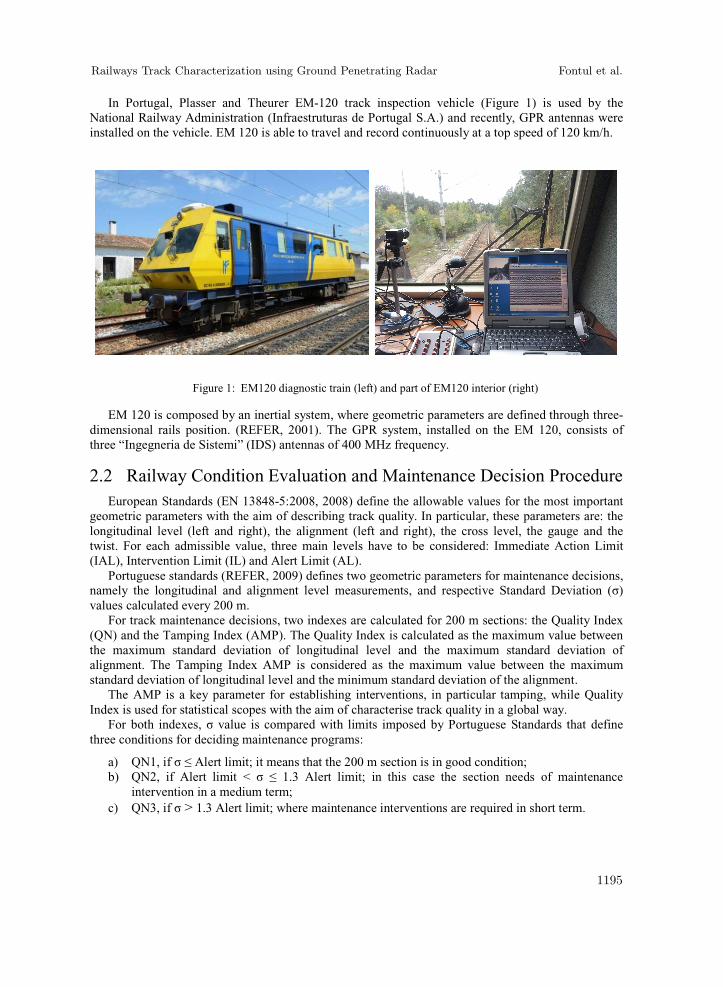
In Portugal, Plasser and Theurer EM-120 track inspection vehicle (Figure 1) is used by the National Railway Administration (Infraestruturas de Portugal S.A.) and recently, GPR antennas were installed on the vehicle. EM 120 is able to travel and record continuously at a top speed of 120 km/h.
Figure 1: EM120 diagnostic train (left) and part of EM120 interior (right)
EM 120 is composed by an inertial system, where geometric parameters are defined through three-dimensional rails position. (REFER, 2001). The GPR system, installed on the EM 120, consists of three “Ingegneria de Sistemi” (IDS) antennas of 400 MHz frequency.
2.2 Railway Condition Evaluation and Maintenance Decision Procedure European Standards (EN 13848-5:2008, 2008) define the allowable values for the most important
geometric parameters with the aim of describing track quality. In particular, these parameters are: the longitudinal level (left and right), the alignment (left and right), the cross level, the gauge and the twist. For each admissible value, three main levels have to be considered: Immediate Action Limit (IAL), Intervention Limit (IL) and Alert Limit (AL).
Portuguese standards (REFER, 2009) defines two geometric parameters for maintenance decisions, namely the longitudinal and alignment level measurements, and respective Standard Deviation ( ) values calculated every 200 m.
For track maintenance decisions, two indexes are calculated for 200 m sections: the Quality Index (QN) and the Tamping Index (AMP). The Quality Index is calculated as the maximum value between the maximum standard deviation of longitudinal level and the maximum standard deviation of alignment. The Tamping Index AMP is considered as the maximum value between the maximum standard deviation of longitudinal level and the minimum standard deviation of the alignment.
The AMP is a key parameter for establishing interventions, in particular tamping, while Quality Index is used for statistical scopes with the aim of characterise track quality in a global way.
For both indexes, value is compared with limits imposed by Portuguese Standards that define three conditions for deciding maintenance programs:
a) QN1, if Alert limit; it means that the 200 m section is in good condition; b) QN2, if Alert limit < 1.3 Alert limit; in this case the section needs of maintenance
intervention in a medium term; c) QN3, if > 1.3 Alert limit; where maintenance interventions are required in short term.
Railways Track Characterization using Ground Penetrating Radar Fontul et al.
1195
The general rule is that a single QN3 value (200 m) or two consecutive QN2 values (200 m plus 200 m) in the annual September campaign means including an intervention into the tamping plan (AMP plan) of the following year. Anyway, some alterations should be considered and included in the AMP plan, for example if consecutive campaigns present twist values near the Alert limit, or a defined section needs geometry correction in terms of cross level, etc.
As already referred, tamping may be performed manually or mechanically. The first option in general occurs when sections have a maximum length of about 20 m. For defining the right length of the section to be corrected, standard deviation values are compared with the graphics of geometric values, measured by EM120. This also for checking if section is in straight or in curve line, as tamping cannot start or finish in a track transition curve.
None of these considerations takes into account other maintenance interventions, such as ballast cleaning. In fact, actually, for economic reasons, cleaning is performed in extreme situations, namely based on visual inspections where the presence of fouling conditions on ballast surface can be noted.
The actual procedure presents some disadvantages, first it consists in treating only the effect and not the causes of the problem. Consequently, the tamping may not solve the problem efficiently, resulting in cost and time consuming interventions. For this reasons, a new methodology has been developed, aiming to find the real causes of track degradation and a case study is presented herein.
3 Alternative Procedure for Characterization of In Service Track
3.1 Proposed Procedure The procedure proposed herein aims to combine geometric parameters, measured by EM120, with
GPR data. The scope is to identify track patterns and to obtain information about the causes of defects in order to treat them, and not only their effects, with appropriate interventions. In addition, a better precision for the location of the defects, not only longitudinally but also in depth, can be obtained. All these factors may lead to time and costs savings and to a better maintenance, providing a longer life cycle of the track.
The methodology can be divided into three main phases, namely: detection of critical areas, GPR results analysis and maintenance intervention decision.
In order to detect the critical areas with deterioration that can be caused by substructure defects an improved method for geometric parameters analysis along the track was developed. This consists in calculating standard deviation values (200 m) in a mobile window, every 0.25 m (that corresponds to the EM120 measurement step), in order to have a continuous trend and not only segmented data, as for the actual methodology, in which the 200 m section used for the calculation of the standard deviation is always fixed.
In addition, GPR measurement analysis is included and, in this way, the length of the deteriorated sections can be even better located.
The visualization of the GPR results also support the maintenance decision, as it can help in defining if tamping is efficient or not, like in case of existing settlements of the substructure. In this way the more appropriate intervention can be adopted and its extension can be better defined. In particular, it can be established if ballast cleaning or renewal are better than tamping, or even if a deeper intervention is required, in case the defect is detected in at formation layer. Therefore, GPR can be useful not only for defining the length of section but also for indicating at which depth it requires intervention.
Railways Track Characterization using Ground Penetrating Radar Fontul et al.
1196

3.2 Case Study This case study aims to present an example where the tamping intervention is not the most proper
maintenance measure. In the procedure generally used the standard deviation is calculated for 200 m fixed sections, represented with dots in Figure 2. For a correct visualization of graphics, it should be taken into account that points (that represents the standard deviation of a 200 m fixed section, calculated nowadays) are positioned in the middle of the 200 m long interval (i.e. the representative point related to interval 158+200-158+400 km is represented in the graph at 158+300 km).
In the example presented herein, in April 2011, the Tamping index (AMP) overcame the Intervention Limit (IL) and for this reason, tamping was performed. After two campaigns, the Tamping index (AMP) overcame the Alert Limit (AL) for two consecutive campaigns, which indicates that at the end of the second year after the intervention, another tamping is required.
The new methodology was applied at this track section. First step, in order to better detect the critical area, was to calculate a continuous standard deviation trends of five monitoring campaigns, presented in Figure 2 together with an example of the classical approach (the dots for the first 200m).
In this case, the choice of the interval to study is more difficult, as trends above Alert limit (AL) limit are of different lengths. Thus, the longer one was studied in terms of GPR measurements, namely from 158+130 to km 158+530 km, that represents the May 2013 campaign. In the GPR measurement file of this section, three different situations can be observed (Figure 3).
Figure 2: Continuous standard deviation of longitudinal level trend along the section and the section selected for GPR study (shadowed)
Figure 3: GPR file of the track section with longitudinal level defects: subsections analysed
Railways Track Characterization using Ground Penetrating Radar Fontul et al.
1197
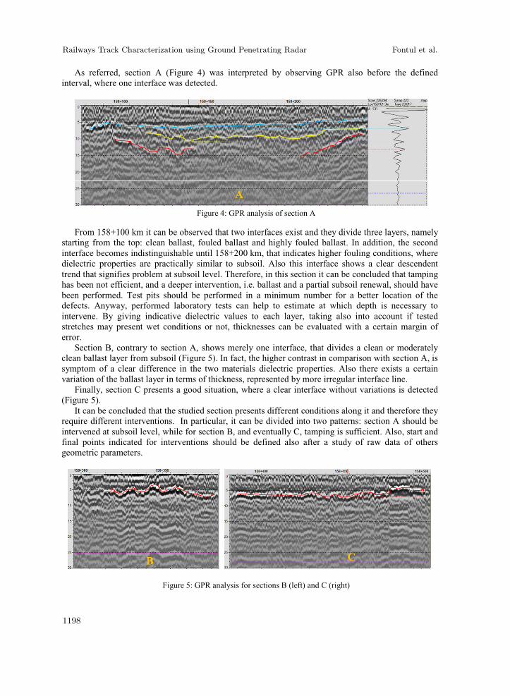
As referred, section A (Figure 4) was interpreted by observing GPR also before the defined interval, where one interface was detected.
Figure 4: GPR analysis of section A
From 158+100 km it can be observed that two interfaces exist and they divide three layers, namely starting from the top: clean ballast, fouled ballast and highly fouled ballast. In addition, the second interface becomes indistinguishable until 158+200 km, that indicates higher fouling conditions, where dielectric properties are practically similar to subsoil. Also this interface shows a clear descendent trend that signifies problem at subsoil level. Therefore, in this section it can be concluded that tamping has been not efficient, and a deeper intervention, i.e. ballast and a partial subsoil renewal, should have been performed. Test pits should be performed in a minimum number for a better location of the defects. Anyway, performed laboratory tests can help to estimate at which depth is necessary to intervene. By giving indicative dielectric values to each layer, taking also into account if tested stretches may present wet conditions or not, thicknesses can be evaluated with a certain margin of error.
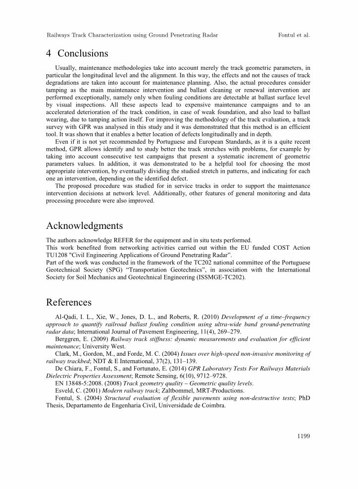
Section B, contrary to section A, shows merely one interface, that divides a clean or moderately clean ballast layer from subsoil (Figure 5). In fact, the higher contrast in comparison with section A, is symptom of a clear difference in the two materials dielectric properties. Also there exists a certain variation of the ballast layer in terms of thickness, represented by more irregular interface line.
Finally, section C presents a good situation, where a clear interface without variations is detected (Figure 5).
It can be concluded that the studied section presents different conditions along it and therefore they require different interventions. In particular, it can be divided into two patterns: section A should be intervened at subsoil level, while for section B, and eventually C, tamping is sufficient. Also, start and final points indicated for interventions should be defined also after a study of raw data of others geometric parameters.
Figure 5: GPR analysis for sections B (left) and C (right)
Railways Track Characterization using Ground Penetrating Radar Fontul et al.
1198
4 Conclusions Usually, maintenance methodologies take into account merely the track geometric parameters, in
particular the longitudinal level and the alignment. In this way, the effects and not the causes of track degradations are taken into account for maintenance planning. Also, the actual procedures consider tamping as the main maintenance intervention and ballast cleaning or renewal intervention are performed exceptionally, namely only when fouling conditions are detectable at ballast surface level by visual inspections. All these aspects lead to expensive maintenance campaigns and to an accelerated deterioration of the track condition, in case of weak foundation, and also lead to ballast wearing, due to tamping action itself. For improving the methodology of the track evaluation, a track survey with GPR was analysed in this study and it was demonstrated that this method is an efficient tool. It was shown that it enables a better location of defects longitudinally and in depth.
Even if it is not yet recommended by Portuguese and European Standards, as it is a quite recent method, GPR allows identify and to study better the track stretches with problems, for example by taking into account consecutive test campaigns that present a systematic increment of geometric parameters values. In addition, it was demonstrated to be a helpful tool for choosing the most appropriate intervention, by eventually dividing the studied stretch in patterns, and indicating for each one an intervention, depending on the identified defect.
The proposed procedure was studied for in service tracks in order to support the maintenance intervention decisions at network level. Additionally, other features of general monitoring and data processing procedure were also improved.
Acknowledgments The authors acknowledge REFER for the equipment and in situ tests performed. This work benefited from networking activities carried out within the EU funded COST Action TU1208 "Civil Engineering Applications of Ground Penetrating Radar”. Part of the work was conducted in the framework of the TC202 national committee of the Portuguese Geotechnical Society (SPG) “Transportation Geotechnics”, in association with the International Society for Soil Mechanics and Geotechnical Engineering (ISSMGE-TC202).
References Al-Qadi, I. L., Xie, W., Jones, D. L., and Roberts, R. (2010) Development of a time–frequency
approach to quantify railroad ballast fouling condition using ultra-wide band ground-penetrating radar data; International Journal of Pavement Engineering, 11(4), 269–279.
Berggren, E. (2009) Railway track stiffness: dynamic measurements and evaluation for efficient maintenance; University West.
Clark, M., Gordon, M., and Forde, M. C. (2004) Issues over high-speed non-invasive monitoring of railway trackbed; NDT & E International, 37(2), 131–139.
De Chiara, F., Fontul, S., and Fortunato, E. (2014) GPR Laboratory Tests For Railways Materials Dielectric Properties Assessment; Remote Sensing, 6(10), 9712–9728.
EN 13848-5:2008. (2008) Track geometry quality – Geometric quality levels. Esveld, C. (2001) Modern railway track; Zaltbommel, MRT-Productions. Fontul, S. (2004) Structural evaluation of flexible pavements using non-destructive tests; PhD
Thesis, Departamento de Engenharia Civil, Universidade de Coimbra.
Railways Track Characterization using Ground Penetrating Radar Fontul et al.
1199

Fontul, S., Fortunato, E., and De Chiara, F. (2011) Non-Destructive Tests for Railway Infrastructure Stiffness Evaluation; B.H.V. Topping, Y. Tsompanakis, Stirlingshire, UK.
Forde, M. C., De Bold, R., O’Connor, G., and Morrissey, J. (2010) New Analysis of Ground Penetrating Radar Testing of a Mixed Railway Trackbed; Transportation Research Board 89th Annual Meeting.
Fortunato, E., Pinelo, A., and Matos Fernandes, M. (2010) Characterization of the fouled ballast layer in the substructure of a 19th century railway track under renewal; Soils and foundations, 50(1), 55–62.
Hyslip, J. P., Chrismer, S., LaValley, M., and Wnek, J. (2012) Track Quality From The Ground Up; AREMA Conference, Chicago, IL.
Hyslip, J. P., Smith, S. S., Olhoeft, G. R., and Selig, E. T. (2003) Assessment of railway track substructure condition using ground penetrating radar; 2003 Annual Conference of AREMA.
Lichtberger, B. (2005) Track compendium: Formation, permanent way, maintenance, economics; Eurailpress.
Loizos, A., Silvast, M., and Dimitrellou, S. (2007) Railway trackbed assessment using the GPR technique; Advanced Characterisation of Pavement Soil Engineering Materials, Vols, 1, 1817–1826.
Manacorda, G., and Simi, A. (2012) Non-destructive inspection and characterization of track bed with microwaves; Ground Penetrating Radar (GPR), 2012 14th International Conference on, 805–810.
Manacorda, G., Morandi, D., Sarri, A., and Staccone, G. (2002) Customized GPR system for railroad track verification; Ninth International Conference on Ground Penetrating Radar (GPR2002), 719–723.
REFER (2001) “VIV02 (EM 120) - Veículo de inspecção de via Descrição dos sistemas de medição, REFER.
REFER. (2009) Tolerâncias dos parâmetros geométricos da via; IT.VIA.018, REFER. Roberts, R., Rudy, J., Al Qadi, I. L., Tutumluer, E., and Boyle, J. (2006) Railroad Ballast Fouling
Detection Using Ground Penetrating Radar–A New Approach Based on Scattering from Voids; Ninth European Conference on NDT.
Saaranketo, T. (2006) Electrical properties of road materials and subgrade soils and the use of ground penetrating radar in traffic infrastructure surveys; University of Oulu.
Shangguan, P., Al-Qadi, I. L., and Leng, Z. (2012) Development of Wavelet Technique to Interpret Ground-Penetrating Radar Data for Quantifying Railroad Ballast Conditions; Transportation Research Record: Journal of the Transportation Research Board, 2289(1), 95–102.
Shao, W., Bouzerdoum, A., Phung, S. L., Su, L., Indraratna, B., and Rujikiatkamjorn, C. (2011) “Automatic classification of ground-penetrating-radar signals for railway-ballast assessment; Geoscience and Remote Sensing, IEEE Transactions on, 49(10), 3961–3972.
Silvast, M., Levomaki, M., Nurmikolu, A., and Noukka, J. (2006) NDT techniques in railway structure analysis; Proceedings of the 7th World Congress on Railway Research, Montreal, Canada, 4–8.
Sussmann, T. R., Maser, K. R., Kutrubes, D., Heyns, F., and Selig, E. T. (2001) Development of Ground Penetrating Radar for railway infrastructure condition detection; 14th EEGS Symposium on the Application of Geophysics to Engineering and Environmental Problems.
Zhang, Q., Gascoyne, J., and Eriksen, A. (2011) Characterisation of ballast materials in trackbed using ground penetrating radar: Part 1; IET, 4A1–4A1.
Railways Track Characterization using Ground Penetrating Radar Fontul et al.
1200