railway geogrid design
DESCRIPTION
Railway geogridTRANSCRIPT

________________________________________________________________________
GEOGRID DESIGN FOR RAILWAY BASE ON SOFT SOIL
by Petrucio Santos
INTRODUCTION
Geogrid reinforcement of roads/railways and parking decks on soft soil needs to be
designed on the base of sound engineering principles.
Geogrids provide the following reinforcing mechanisms:
- base course lateral restrain mechanism for horizontal stresses generated by deck soil
self weight;
- base course lateral restrain mechanism for horizontal stresses generated by wheels
loading;
- membrane mechanism at the deck – subgrade interface.
Each of these three mechanisms produce tensile forces in geogrid reinforcement layers.
The general scheme of a road or a parking deck may include the following layers:
- asphalt course AC (the wearing course and the binder layer are considered as one only
layer whose thickness is the total thickness of the two ones);
- base course BC;
- subbase course SB;
- subgrade SG.
Therefore a 4 layers model has been developed for geogrid design: the general scheme of
the model and all symbols, that will be used for subsequent calculations, are shown in
the following Figure.
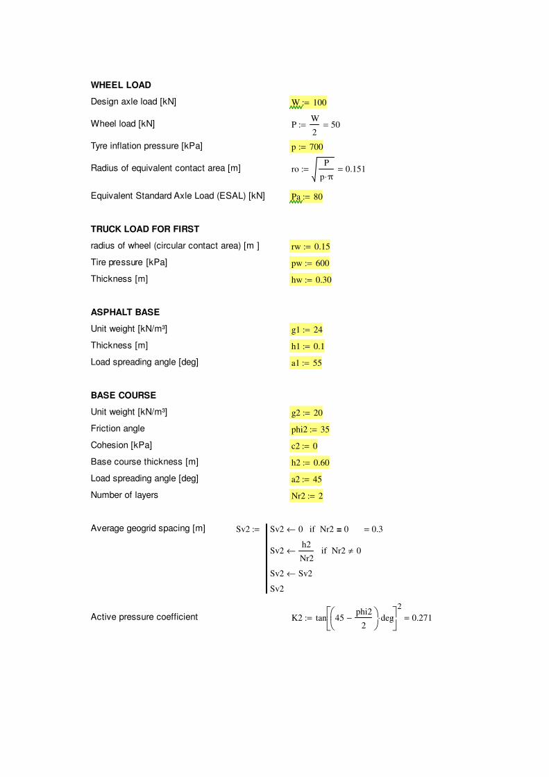
WHEEL LOAD
Design axle load [kN] W 100:=
Wheel load [kN] PW
250=:=
Tyre inflation pressure [kPa] p 700:=
Radius of equivalent contact area [m] roP
p π⋅0.151=:=
Equivalent Standard Axle Load (ESAL) [kN] Pa 80:=
TRUCK LOAD FOR FIRST
radius of wheel (circular contact area) [m ] rw 0.15:=
Tire pressure [kPa] pw 600:=
Thickness [m] hw 0.30:=
ASPHALT BASE
Unit weight [kN/m³] g1 24:=
Thickness [m] h1 0.1:=
Load spreading angle [deg] a1 55:=
BASE COURSE
Unit weight [kN/m³] g2 20:=
Friction angle phi2 35:=
Cohesion [kPa] c2 0:=
Base course thickness [m] h2 0.60:=
Load spreading angle [deg] a2 45:=
Number of layers Nr2 2:=
Average geogrid spacing [m] Sv2 Sv2 0← Nr2 0=if
Sv2h2
Nr2← Nr2 0≠if
Sv2 Sv2←
Sv2
0.3=:=
Active pressure coefficient K2 tan 45phi2
2−
deg⋅
2
0.271=:=

SUBBASE COURSE
Unit weight [kN/m³] g3 18:=
Friction angle [deg] phi3 35:=
Cohesion [kPa] c3 0:=
Subbase course thickness [m] h3 0.3:=
Load spreading angle [deg] a3 40:=
Number of layers Nr3 1:=
Average geogrid spacing [m] Sv3 Sv3 0← Nr3 0=if
Sv3h3
Nr3← Nr3 0≠if
Sv3 Sv3←
Sv3
0.3=:=
Active pressure coefficient K3 tan 45phi3
2−
deg⋅
2
0.271=:=
SUBGRADE
CBR CBRsg 1:=
FS BEARING CAPACITY FSbc 3:=
MEMBRANE THEORY COEFFICIENT
omg e( ) om 2.07← e 1=if
om 1.47← e 2=if
om 1.23← e 3=if
om 1.08← e 4=if
om 0.97← e 5=if
om
:=

VALUES AT LAYERS INTERFACES
Asphalt layer bottom
z1 h1 0.1=:=
r1 ro z1 tan a1 deg⋅( )⋅+ 0.294=:=
sv1 pro
2
r12
⋅ 184.631=:=
Base course bottom
z2 h1 h2+ 0.7=:=
r2 r1 z2 z1−( ) tan a2 deg⋅( )⋅+ 0.894=:=
sv2 sv1r1
2
r22
⋅ 19.931=:=
Subbase bottom
z3 h1 h2+ h3+ 1=:=
r3 r2 z3 z2−( ) tan a3 deg⋅( )⋅+ 1.145=:=
sv3 sv2r2
2
r32
⋅ 12.133=:=
GEOGRID DESIGN FOR BASE COURSE
LAYER NUMBER (until 5 layers)
Position of reinforcement from
base course bottomPosition of reinforcement from top of layer
Hbc
0
0.30
0
0
0
0
:= Zbc i 0←
Zi
z1← i Nr2( )≥if
Zi
z2 Hbci
−← i Nr2<if
i 0 5..∈for
Zbc Z←
Zbc
0.7
0.4
0.1
0.1
0.1
0.1
=:=

Horizontal forces acting:
Soil_Thrust
Wheel_Loading
j 0←
Tzj
0←
rj
r1←
svj
0←
j Nr2 1+≥if
Tzj
0.5 K2⋅ 2 g1⋅ h1⋅ g2 Zbcj
Zbcj 1+
+ 2 h1⋅−( )⋅+ ⋅ Zbc
jZbc
j 1+−( )⋅←
rj
r1 Zbcj
z1−( ) tan a2 deg⋅( )⋅+←
svj
sv1r1
2
rj( )
2
⋅←
j Nr2 1+<if
j 0 5..∈for
Tpk
0.5 K2⋅ svk
svk 1+
+( )⋅ Zbck
Zbck 1+
−( )⋅← k Nr2 1+<if
Tpk
0← k Nr2 1+≥if
k 0 5..∈for
Tz Tz←
Tp Tp←
Tz
Tp
:=
Soil_Thrust
0.927
0.439
0
0
0
0
= Wheel_Loading
2.646
9.341
0
0
0
0
=
First_lift_ro rw 0.15=:=
First_lift_hw hw 0.3=:=
First_lift_rf First_lift_ro First_lift_hw tan a2 deg⋅( )⋅+ 0.45=:=
First_lift_tp pw 600=:=
First_lift_Afπ
4
First_lift_rf2
⋅ 0.159=:=

Wtc2 Wtc2 0← h3 0>if
W11
3g2⋅
First_lift_rf3
First_lift_ro3
−( )
First_lift_rf2
tan a2 deg⋅( )⋅( )⋅←
W2 First_lift_tpFirst_lift_ro
2
First_lift_rf2
⋅ 60 π⋅CBRsg
FSbc
⋅−←
Wtc2 W1 W2+←
h3 0≤if
Wtc2 Wtc2←
Wtc2
0=:=
εr2 3:=
omega omg εr2( ) 1.23=:=
Tm2 Tm2 0← h3 0>if
Tm2 0← Wtc2 0≤if
Tm2 Wtc2 First_lift_rf⋅ omega⋅← Wtc2 0>if
h3 0≤if
Tm2 Tm2←
Tm2
0=:=
Tot Soil_Thrust Wheel_Loading+
3.573
9.78
0
0
0
0
=:=
Tot0
Soil_Thrust0
Wheel_Loading0
+ Tm2+:=Tot
3.573
9.78
0
0
0
0
=

GEOGRID DESIGN FOR SUBBASE COURSE
LAYER NUMBER (until 5 layers)
Position of reinforcement from
base course bottomPosition of reinforcement from top of layer
Hsbc
0
0
0
0
0
0
:= Zsbc i 0←
Zi
z2← i Nr3( )≥if
Zi
z3( ) Hsbci
−← i Nr3<if
i 0 5..∈for
Zsbc Z←
Zsbc
1
0.7
0.7
0.7
0.7
0.7
=:=
Horizontal forces acting:
Soil_Thrust_sb
Wheel_Loading_sb
j 0←
Tzj
0←
rj
r1←
svj
0←
j Nr3 1+≥if
CTE1 g3 Zsbcj
Zsbcj 1+
+ 2 h2⋅−( )⋅←
CTE2 Zsbcj
Zsbcj 1+
−( )←
Tzj
0.5 K3⋅ 2 g1 h1⋅ g2 h2⋅+ 2 h2⋅−( )⋅ CTE1+[ ]⋅ CTE2⋅←
rj
r2 Zsbcj
z2−( ) tan a3 deg⋅( )⋅+←
svj
sv2r2
2
rj( )
2
⋅←
j Nr3 1+<if
j 0 5..∈for
Tpk
0.5 K3⋅ svk
svk 1+
+( )⋅ Zsbck
Zsbck 1+
−( )⋅← k Nr3 1+<if
Tpk
0← k Nr3 1+≥if
k 0 5..∈for
Tz Tz←
Tp Tp←
Tz
Tp
:=

Soil_Thrust_sb
1.439
0
0
0
0
0
= Wheel_Loading_sb
1.303
0
0
0
0
0
=
First_lift_ros rw 0.15=:=
First_lift_hws hw 0.3=:=
First_lift_rfs First_lift_ro First_lift_hw tan a3 deg⋅( )⋅+ 0.402=:=
First_lift_tps pw 600=:=
First_lift_Afsπ
4
First_lift_rfs2
⋅ 0.127=:=
Wtc3 Wtc3 0← h3 0=if
W11
3g3⋅
First_lift_rfs3
First_lift_ros3
−( )
First_lift_rfs2
tan a3 deg⋅( )⋅( )⋅←
W2 First_lift_tpFirst_lift_ros
2
First_lift_rfs2
⋅ 60 π⋅CBRsg
FSbc
⋅−←
Wtc3 W1 W2+←
h3 0≠if
Wtc3 Wtc3←
Wtc3
23.541=:=
εr3 3:=
omega2 omg εr3( ) 1.23=:=
Tm3 Tm3 0← h3 0=if
Tm3 0← Wtc3 0≤if
Tm3 Wtc3 First_lift_rfs⋅ omega2⋅← Wtc3 0>if
h3 0≠if
Tm3 Tm3←
Tm3
11.632=:=

Tot_sb Soil_Thrust_sb Wheel_Loading_sb+
2.742
0
0
0
0
0
=:=
Tot_sb0
Soil_Thrust_sb0
Wheel_Loading_sb0
+ Tm3+:=
Tot_sb
14.375
0
0
0
0
0
=

