radio network simulation - commsys.isy.liu.se · amplitude, phase, and angle (at tx and rx side)...
TRANSCRIPT
RADIO NETWORK SIMULATION
Niclas WibergEricsson Research
Radio Network Simulation 2011-09-012
Outline
Simulator overview– What is radio network simulation?
Models– The radio environment
Deployment & mobilityPropagation
– Physical layer– Protocols– Traffic
Radio resource management
Simulation methodology

Radio Network Simulation 2011-09-013
Wireless Communication Simulation
Traditional network simulators– ns-2, ns-3, OPNET, OMNET++– Focus on the network and its protocols– Large networks (many hosts)– Wireless modules are available
Wireless link simulators– COSSAP, proprietary, ...– Radio propagation, signal processing– One or a few links
Radio network simulators– Mostly proprietary– Many transmitters and receivers– Focus on radio resources
Radio Network Simulation 2011-09-014
What is Radio Network Simulation?
“Simulating performance in terms of coverage, capacity and quality in a multi-cell system”
environment deployment
mobility & trafficalg. parameters
...
Radio Network Simulator
transmit powerinterferenceerror rates
...
throughputservice qualityblock ratedrop rate...
Radio Network Simulation 2011-09-015
Radio Network Simulation
Mobility Deployment
Internet Protocols
Radio Protocols
Propagation & Fading
Physical Layer
RRM
Application Traffic
TransportNetwork
Radio Network Simulation 2011-09-016
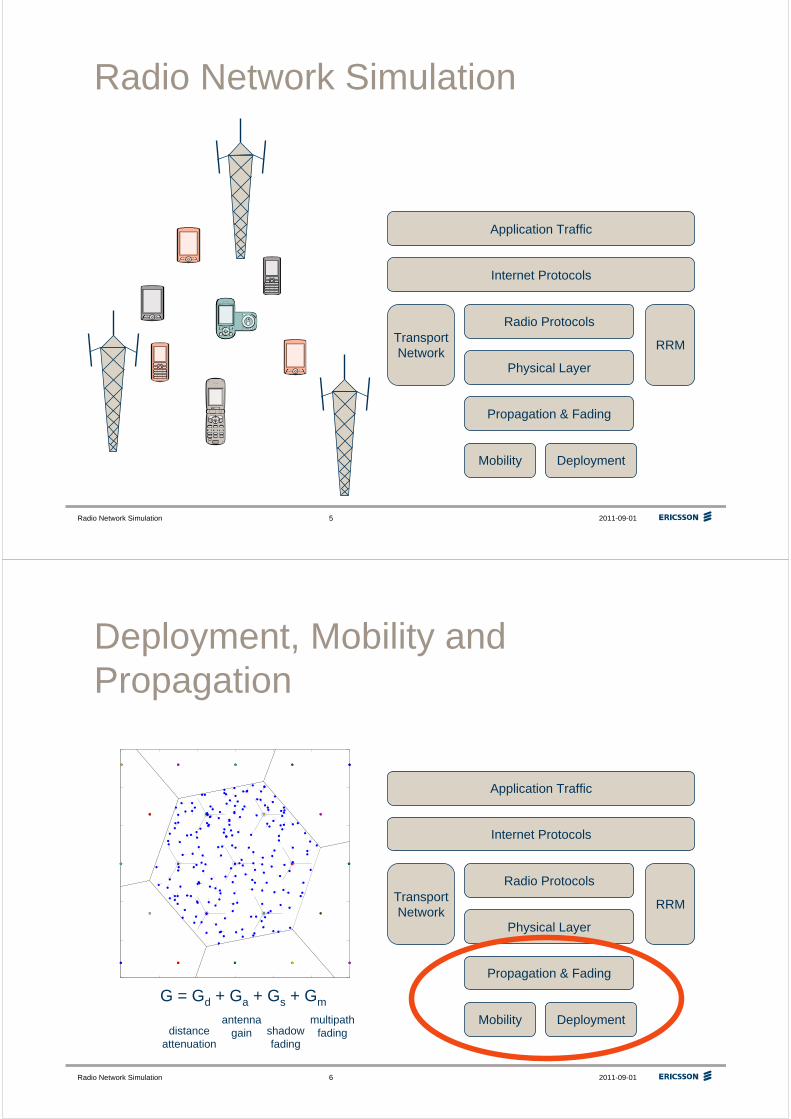
Deployment, Mobility and Propagation
G = Gd + Ga + Gs + Gm
distance attenuation
antenna gain shadow
fading
multipath fading
Mobility Deployment
Internet Protocols
Radio Protocols
Propagation & Fading
Physical Layer
RRM
Application Traffic
TransportNetwork
Radio Network Simulation 2011-09-017
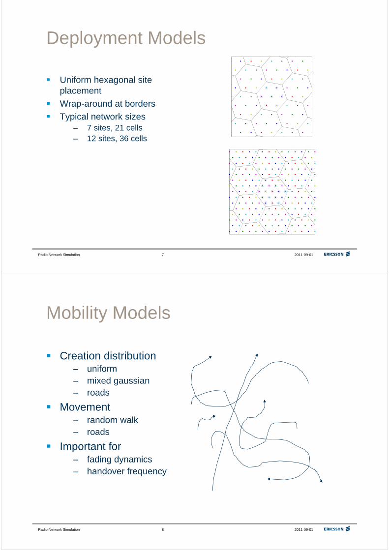
Deployment Models
Uniform hexagonal site placement
Wrap-around at borders
Typical network sizes– 7 sites, 21 cells– 12 sites, 36 cells
Radio Network Simulation 2011-09-018
Mobility Models
Creation distribution– uniform– mixed gaussian– roads
Movement– random walk– roads
Important for– fading dynamics– handover frequency
Radio Network Simulation 2011-09-019
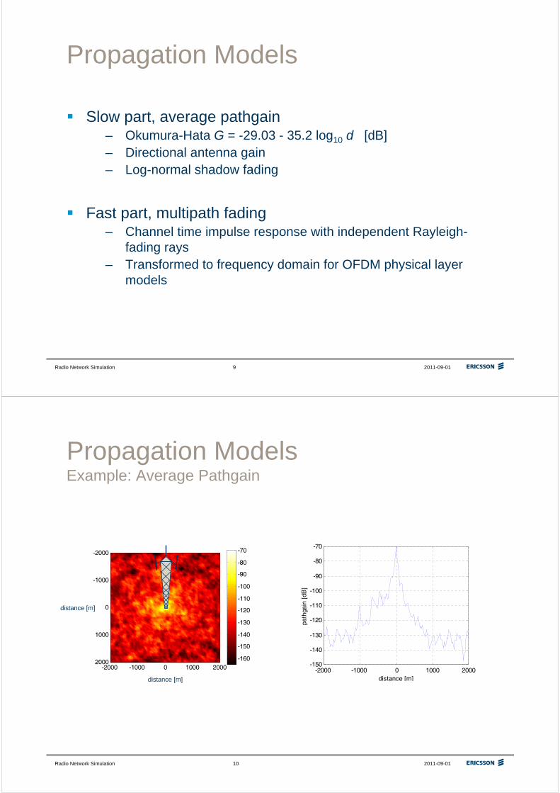
Propagation Models
Slow part, average pathgain– Okumura-Hata G = -29.03 - 35.2 log10 d [dB]– Directional antenna gain– Log-normal shadow fading
Fast part, multipath fading– Channel time impulse response with independent Rayleigh-
fading rays– Transformed to frequency domain for OFDM physical layer
models
Radio Network Simulation 2011-09-0110
Propagation ModelsExample: Average Pathgain
-160
-150
-140
-130
-120
-110
-100
-90
-80
-70
-2000 -1000 0 1000 2000
-2000
-1000
0
1000
2000-2000 -1000 0 1000 2000
-150
-140
-130
-120
-110
-100
-90
-80
-70
distance [m]
path
gain
[dB
]
distance [m]
distance [m]
Radio Network Simulation 2011-09-0111
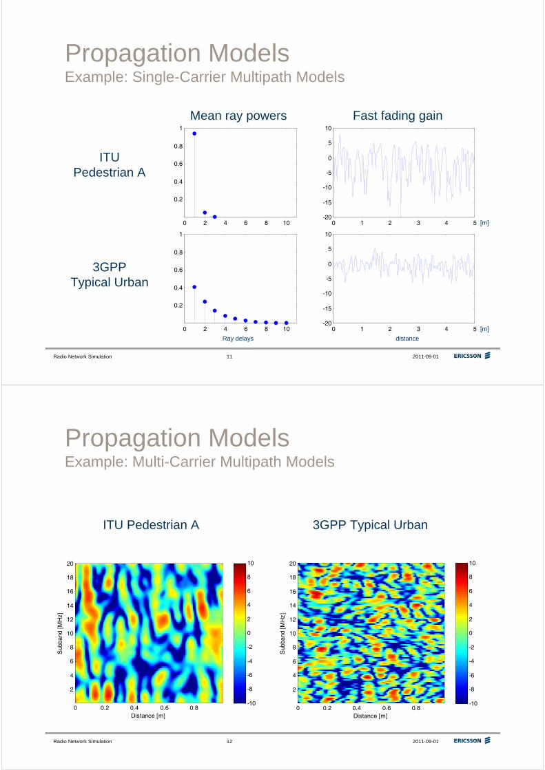
Propagation ModelsExample: Single-Carrier Multipath Models
0 2 4 6 8 10
0.2
0.4
0.6
0.8
1
0 2 4 6 8 10
0.2
0.4
0.6
0.8
1
0 1 2 3 4 5-20
-15
-10
-5
0
5
10
0 1 2 3 4 5-20
-15
-10
-5
0
5
10
ITUPedestrian A
3GPPTypical Urban
Mean ray powers Fast fading gain
[m]
[m]
distanceRay delays
Radio Network Simulation 2011-09-0112
Propagation ModelsExample: Multi-Carrier Multipath Models
ITU Pedestrian A 3GPP Typical Urban
Distance [m]
Sub
band
[M
Hz]
0 0.2 0.4 0.6 0.8
2
4
6
8
10
12
14
16
18
20
-10
-8
-6
-4
-2
0
2
4
6
8
10
Distance [m]
Sub
band
[M
Hz]
0 0.2 0.4 0.6 0.8
2
4
6
8
10
12
14
16
18
20
-10
-8
-6
-4
-2
0
2
4
6
8
10
Radio Network Simulation 2011-09-0113
-1000 -500 0 500 1000
-1500
-1000
-500
0
500
1000
1500
1
2
3
4
5
6
7
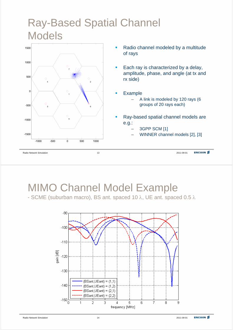
Ray-Based Spatial Channel Models
Radio channel modeled by a multitude of rays
Each ray is characterized by a delay, amplitude, phase, and angle (at tx and rx side)
Example– A link is modeled by 120 rays (6
groups of 20 rays each)
Ray-based spatial channel models are e.g.:
– 3GPP SCM [1]– WINNER channel models [2], [3]
Radio Network Simulation 2011-09-0114
MIMO Channel Model Example- SCME (suburban macro), BS ant. spaced 10 λ, UE ant. spaced 0.5 λ
Radio Network Simulation 2011-09-0115
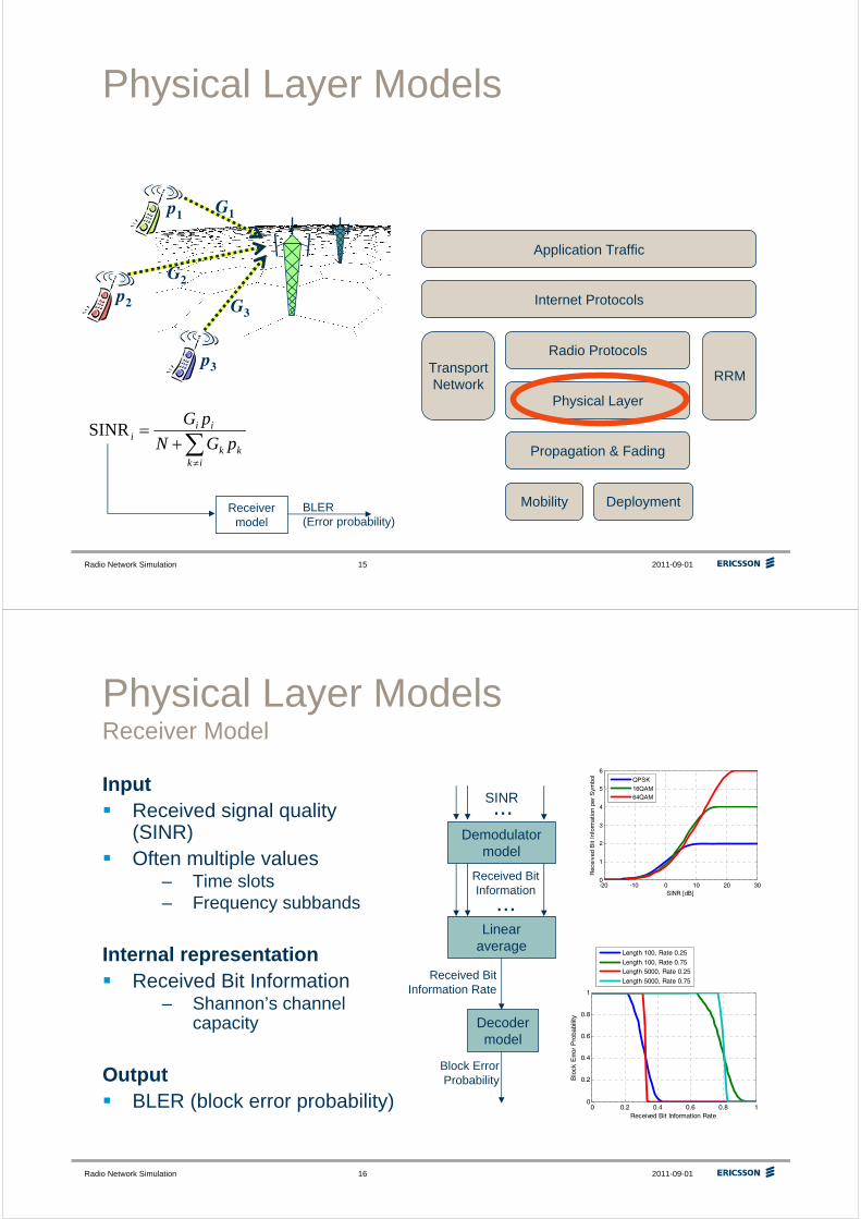
Physical Layer Models
Receivermodel
BLER(Error probability)
Mobility Deployment
Internet Protocols
Radio Protocols
Propagation & Fading
Physical Layer
RRM
Application Traffic
TransportNetwork
p1
∑≠
+=
ikkk
iii pGN
pGSINR
p2
p3
G1
G2
G3
Radio Network Simulation 2011-09-0116
Physical Layer ModelsReceiver Model
InputReceived signal quality (SINR)Often multiple values
– Time slots– Frequency subbands
Internal representationReceived Bit Information
– Shannon’s channel capacity
OutputBLER (block error probability)
Decoder model
Linear average
...
Received BitInformation
Demodulator model
SINR
...
Received BitInformation Rate
Block ErrorProbability
-20 -10 0 10 20 300
1
2
3
4
5
6
SINR [dB]
Rec
eive
d B
it In
form
atio
n pe
r S
ymbo
l
QPSK
16QAM64QAM
0 0.2 0.4 0.6 0.8 10
0.2
0.4
0.6
0.8
1
Received Bit Information Rate
Blo
ck E
rror
Pro
babi
lity
Length 100, Rate 0.25
Length 100, Rate 0.75Length 5000, Rate 0.25
Length 5000, Rate 0.75
Radio Network Simulation 2011-09-0117
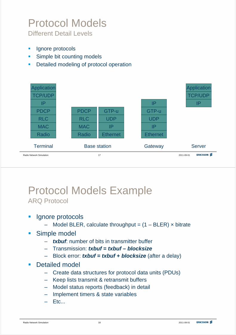
Protocol ModelsDifferent Detail Levels
Ignore protocols
Simple bit counting models
Detailed modeling of protocol operation
Radio
MAC
RLC
PDCP
IP
TCP/UDP
Application
Radio
MAC
RLC
PDCP GTP-u
UDP
IP
Ethernet
GTP-u
UDP
IP
Ethernet
IP
TCP/UDP
Application
IP
Terminal Base station Gateway Server
Radio Network Simulation 2011-09-0118
Protocol Models ExampleARQ Protocol
Ignore protocols– Model BLER, calculate throughput = (1 – BLER) × bitrate
Simple model– txbuf: number of bits in transmitter buffer– Transmission: txbuf = txbuf – blocksize– Block error: txbuf = txbuf + blocksize (after a delay)
Detailed model– Create data structures for protocol data units (PDUs)– Keep lists transmit & retransmit buffers– Model status reports (feedback) in detail– Implement timers & state variables– Etc...
Radio Network Simulation 2011-09-0119
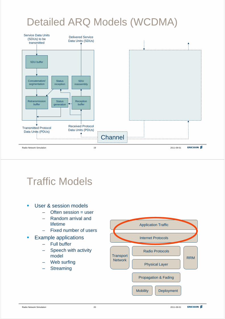
Detailed ARQ Models (WCDMA)
SDU buffer
Service Data Units (SDUs) to be transmitted
Retransmission buffer
Transmitted Protocol Data Units (PDUs)
Reception buffer
SDU reassembly
Delivered Service Data Units (SDUs)
Received Protocol Data Units (PDUs)
Concatenation/segmentation
Status generation
Channel
Status reception
Radio Network Simulation 2011-09-0120
Traffic Models
User & session models– Often session = user– Random arrival and
lifetime– Fixed number of users
Example applications– Full buffer– Speech with activity
model– Web surfing– Streaming
Mobility Deployment
Internet Protocols
Radio Protocols
Propagation & Fading
Physical Layer
RRM
Application Traffic
TransportNetwork
Radio Network Simulation 2011-09-0121
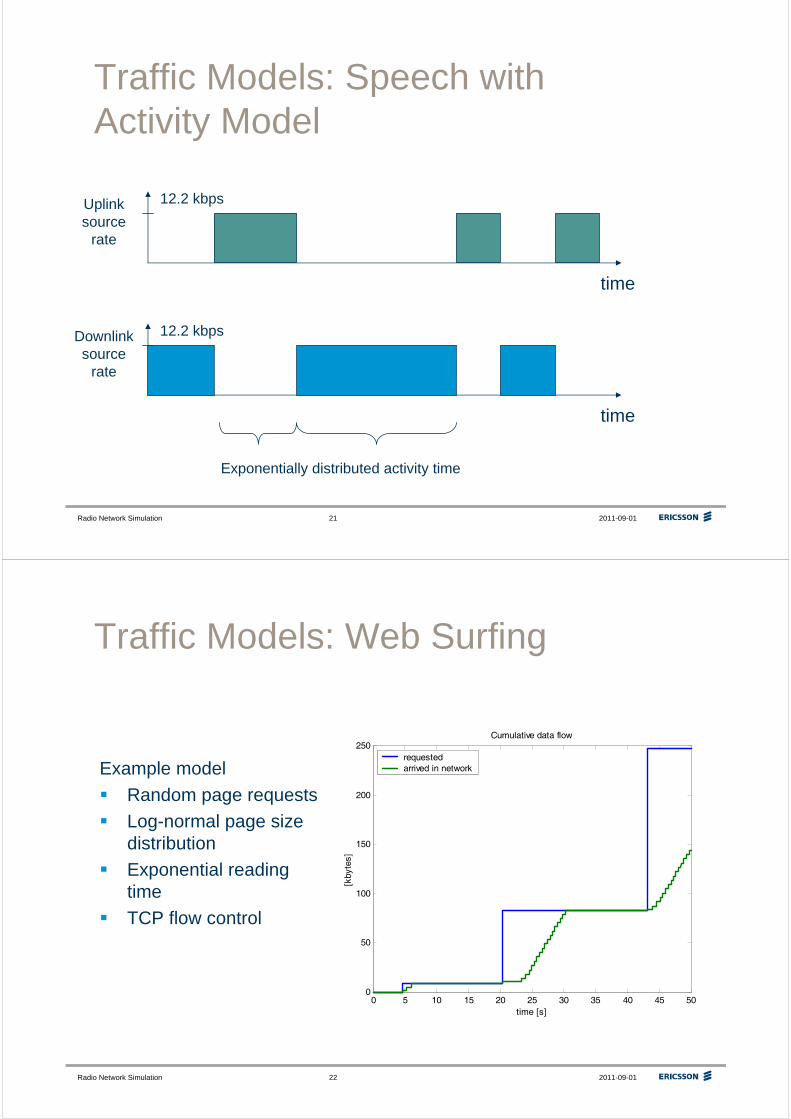
Traffic Models: Speech with Activity Model
time
Uplink source
rate
12.2 kbps
time
Downlink source
rate
12.2 kbps
Exponentially distributed activity time
Radio Network Simulation 2011-09-0122
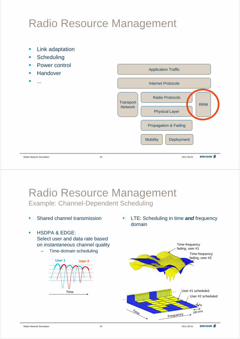
Traffic Models: Web Surfing
Example model
Random page requests
Log-normal page size distribution
Exponential readingtime
TCP flow control
0 5 10 15 20 25 30 35 40 45 500
50
100
150
200
250
time [s]
[kby
tes]
Cumulative data flow
requested arrived in network
Radio Network Simulation 2011-09-0123
Radio Resource Management
Link adaptation
Scheduling
Power control
Handover
...
Mobility Deployment
Internet Protocols
Radio Protocols
Propagation & Fading
Physical Layer
RRM
Application Traffic
TransportNetwork
Radio Network Simulation 2011-09-0124
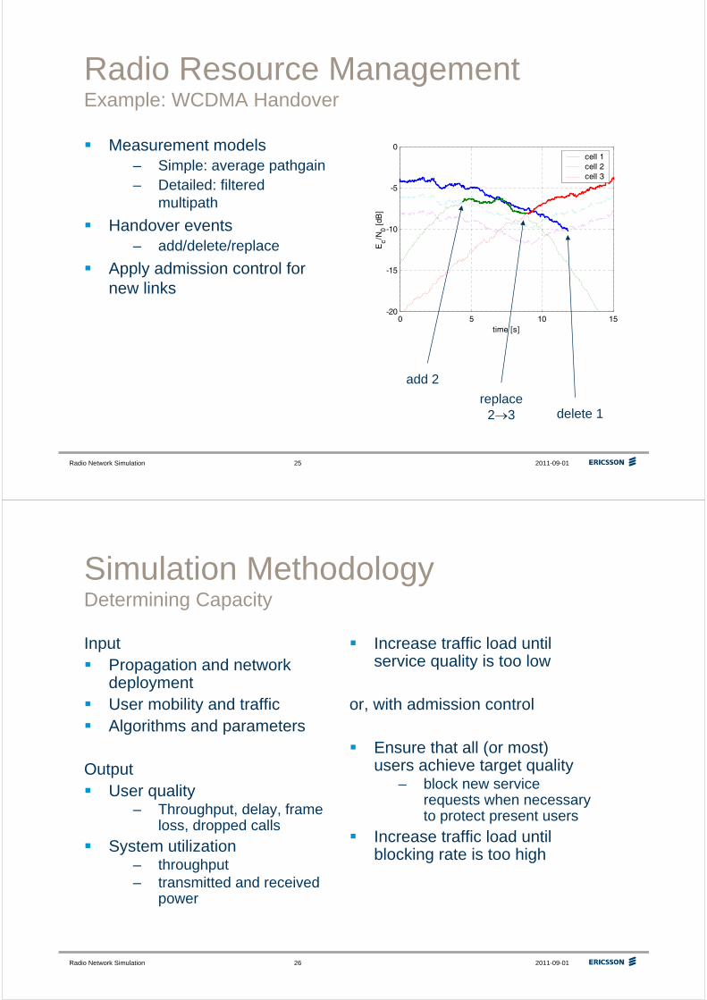
Radio Resource ManagementExample: Channel-Dependent Scheduling
Shared channel transmission
HSDPA & EDGE:Select user and data rate based on instantaneous channel quality
– Time-domain schedulingdata1data2data3data4
TimeFrequency
User #1 scheduled
User #2 scheduled
1 ms
180 kHz
Time-frequency fading, user #1
Time-frequency fading, user #2
LTE: Scheduling in time and frequency domain
Time
User 1 User 2
Radio Network Simulation 2011-09-0125
0 5 10 15-20
-15
-10
-5
0
time [s]
Ec/N
0 [dB
]
cell 1cell 2cell 3
Radio Resource ManagementExample: WCDMA Handover
Measurement models– Simple: average pathgain– Detailed: filtered
multipath
Handover events– add/delete/replace
Apply admission control for new links
delete 1
add 2
replace 2→3
Radio Network Simulation 2011-09-0126
Simulation MethodologyDetermining Capacity
InputPropagation and network deploymentUser mobility and trafficAlgorithms and parameters
OutputUser quality
– Throughput, delay, frame loss, dropped calls
System utilization– throughput– transmitted and received
power
Increase traffic load until service quality is too low
or, with admission control
Ensure that all (or most) users achieve target quality
– block new service requests when necessary to protect present users
Increase traffic load until blocking rate is too high
Radio Network Simulation 2011-09-0127
Simulation MethodologySpeech Capacity
User generation– Random arrival process, or– Fixed number of users
Monitor user quality– Blocking and dropping– Frame loss/drop
Increase #users until less than e.g., 98% are satisfied
Optimize algorithm parameters
Radio Network Simulation 2011-09-0128
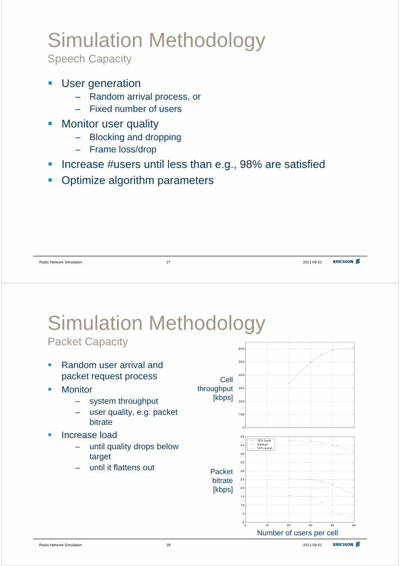
Simulation MethodologyPacket Capacity
Random user arrival and packet request process
Monitor– system throughput– user quality, e.g. packet
bitrate
Increase load– until quality drops below
target– until it flattens out
0 10 20 3 0 40 500
10 0
20 0
30 0
40 0
50 0
60 0
0 10 20 3 0 40 500
5
1 0
1 5
2 0
2 5
3 0
3 5
4 0
4 5
5 010% b est median 10% wors t
Number of users per cell
Packet bitrate[kbps]
Cell throughput
[kbps]
Radio Network Simulation 2011-09-0129
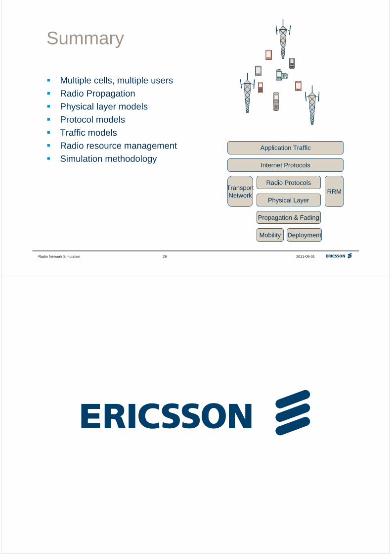
Summary
Multiple cells, multiple users
Radio Propagation
Physical layer models
Protocol models
Traffic models
Radio resource management
Simulation methodology
Mobility Deployment
Internet Protocols
Radio Protocols
Propagation & Fading
Physical LayerRRM
Application Traffic
TransportNetwork
Radio Network Simulation 2011-09-0130