radiation safety training module: diagnostic radiology planning … · 2017-05-22 · radiation...
TRANSCRIPT
Radiation Safety Training Module: Diagnostic Radiology
Planning of Diagnostic X-ray Installations
Radiological Safety Division
Atomic Energy Regulatory Board
Contents
• Expected questions to know after studying
this lecture
• Introduction
• Types of Radiation
• Shielding
• Various Modalities of Diagnostic X-ray
Equipment
• General Principles of Planning of X-ray
Installations
• Codal Requirements for Room Layout Plan
of X-ray
• Installation
• General Recommendations for
Layout Planning
• Reference Data on shielding of X-ray
Installation Room
• Summary
• Expected Questions
• References and sources for additional
information

Expected questions to know after studying this lecture
• What is the purpose of layout planning of X-ray Installation?
• What is Half value Thickness of shielding material?
• What is Tenth Value Thickness of shielding material?
• What do you mean by workload of an X-ray installation?
• Understanding the concepts of Use factor and Occupancy factor.
• AERB Dose limits of worker and members of public.
INTRODUCTION
• Radiation safety is important in diagnostic radiology, not only because of regulatory requirements but also because of radiation workers, members of public and patient safety considerations.
• In Radiation Protection, the guiding philosophy is ALARA (as low as reasonably achievable).
• In Diagnostic Radiology, the main source of occupational exposure is scattered radiation from the patient – particularly in fluoroscopically guided procedures.

OBJECTIVES
The Objective of radiation shielding in diagnostic x-ray facilities is to protect
• Workers of X- ray department
• Members of the Public
• Persons working adjacent to or near the X-ray facility
The purpose of layout planning of medical X-ray facility is to ensure that radiation
exposure to radiation workers and members of the public does not exceed the dose limits
prescribed by competent authority( i.e. Chairman, AERB).
Types of Radiation
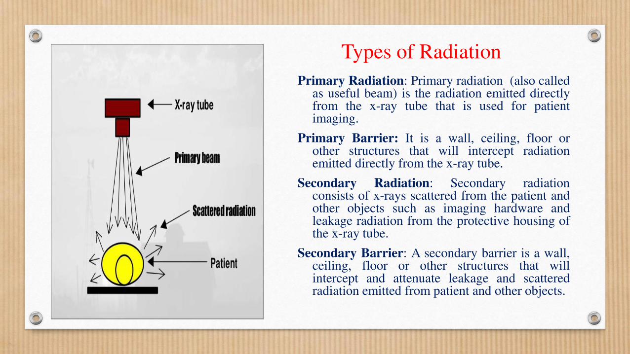
Primary Radiation: Primary radiation (also called as useful beam) is the radiation emitted directly from the x-ray tube that is used for patient imaging.
Primary Barrier: It is a wall, ceiling, floor or other structures that will intercept radiation emitted directly from the x-ray tube.
Secondary Radiation: Secondary radiation consists of x-rays scattered from the patient and other objects such as imaging hardware and leakage radiation from the protective housing of the x-ray tube.
Secondary Barrier: A secondary barrier is a wall, ceiling, floor or other structures that will intercept and attenuate leakage and scattered radiation emitted from patient and other objects.

SHIELDING
• Shielding in diagnostic radiology is used to reduce exposure to radiation workers and the members of general public. The decision to utilize shielding, its type and thickness are functions of photon energy and intensity of ionizing radiation.
• As the thickness of the shielding material is interposed between X-ray beam and the point of interest (e.g. location of technologist) increases, the exposure rate decreases exponentially.
• If I0 (R/Min) is the intensity of radiation beam at a point without shielding and I (R/Min) is the intensity when a thickness (t) of a shielding material is interposed between the source and the point .
• I = I0 e - t
• where is called the linear attenuation coefficient and represents the fraction of x-ray energy removed from the incident beam by unit thickness of the shielding material.
I/I0 = e - t
I0/I = e t
loge (I0/I)= t
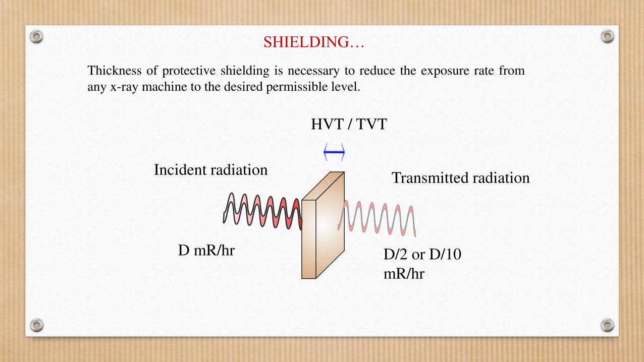
SHIELDING…
Incident radiation Transmitted radiation
HVT / TVT
D mR/hr D/2 or D/10
mR/hr
Thickness of protective shielding is necessary to reduce the exposure rate from
any x-ray machine to the desired permissible level.
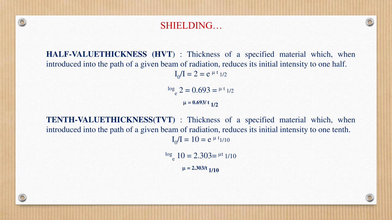
HALF-VALUETHICKNESS (HVT) : Thickness of a specified material which, when
introduced into the path of a given beam of radiation, reduces its initial intensity to one half.
I0/I = 2 = e t 1/2
loge 2 = 0.693 = t 1/2
= 0.693/ t 1/2
TENTH-VALUETHICKNESS(TVT) : Thickness of a specified material which, when
introduced into the path of a given beam of radiation, reduces its initial intensity to one tenth.
I0/I = 10 = e t1/10
loge 10 = 2.303= t 1/10
= 2.303/t 1/10
SHIELDING…

Peak Voltage
(kV)
Lead (mm)
HVL
Concrete (cm)
HVL
50 0.06 0.43
100 0.27 1.6
125 0.28 2.0
Peak Voltage
(kV)
Lead (mm)
TVL
Concrete (cm)
TVL
50 0.17 1.5
100 0.88 5.3
125 0.93 6.6
SHIELDING…
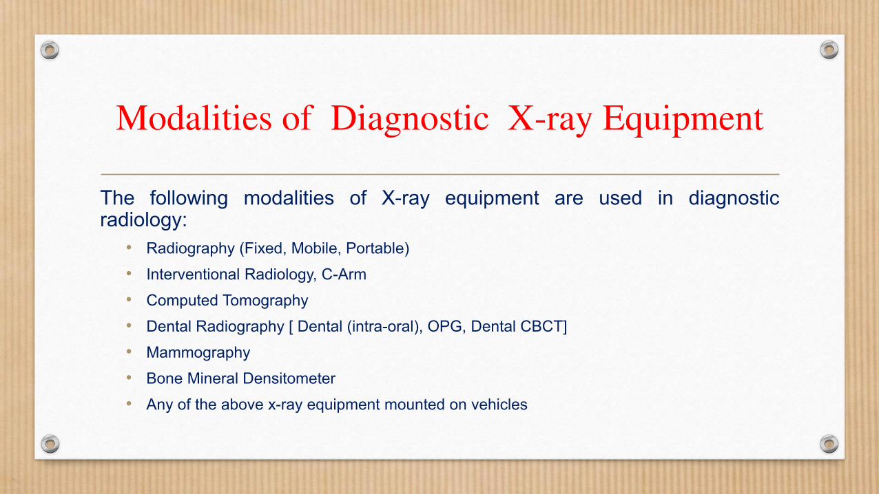
Modalities of Diagnostic X-ray Equipment
The following modalities of X-ray equipment are used in diagnostic radiology:
• Radiography (Fixed, Mobile, Portable)
• Interventional Radiology, C-Arm
• Computed Tomography
• Dental Radiography [ Dental (intra-oral), OPG, Dental CBCT]
• Mammography
• Bone Mineral Densitometer
• Any of the above x-ray equipment mounted on vehicles
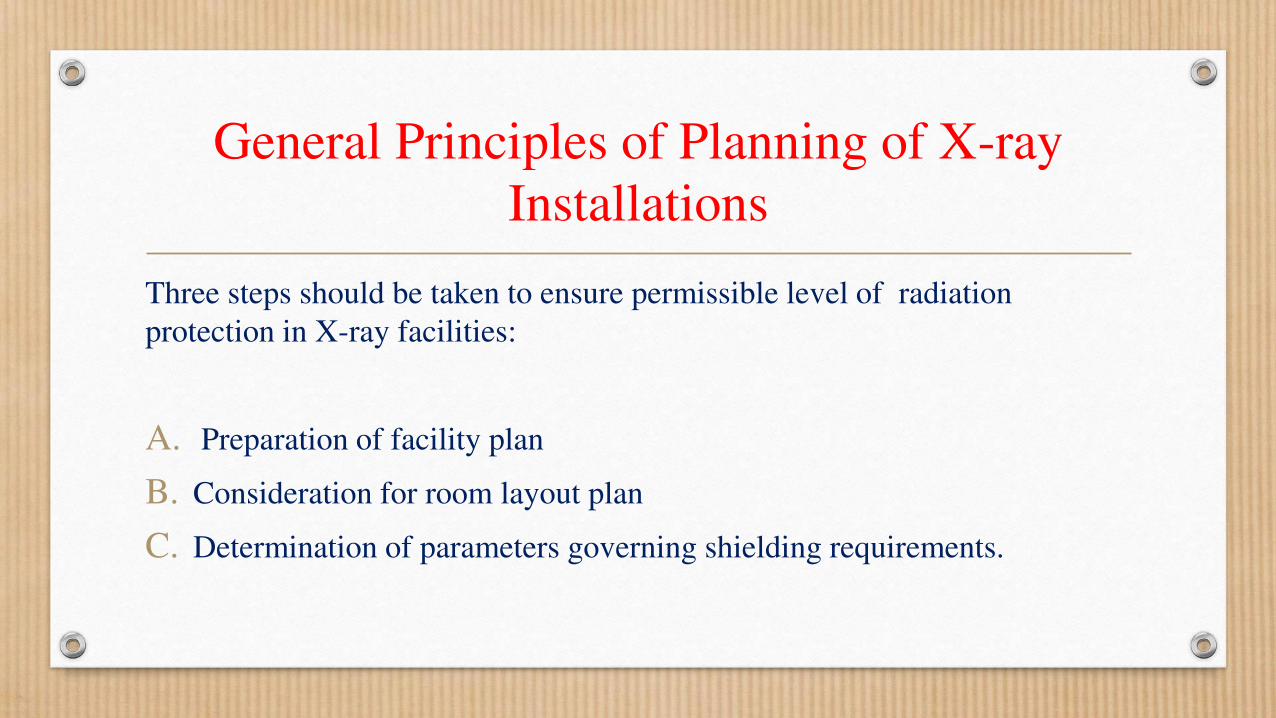
General Principles of Planning of X-ray
Installations
Three steps should be taken to ensure permissible level of radiation
protection in X-ray facilities:
A. Preparation of facility plan
B. Consideration for room layout plan
C. Determination of parameters governing shielding requirements.
General Principles of Planning of X-ray
Installations
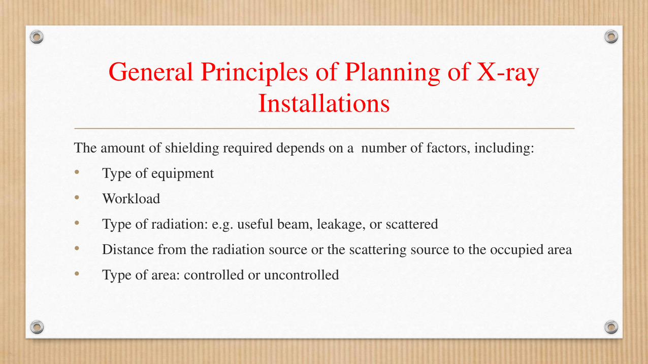
The amount of shielding required depends on a number of factors, including:
• Type of equipment
• Workload
• Type of radiation: e.g. useful beam, leakage, or scattered
• Distance from the radiation source or the scattering source to the occupied area
• Type of area: controlled or uncontrolled

General Principles of Planning of X-ray
Installations…
Workload in Diagnostic Radiology
• Workload is the X-ray unit output/week at well defined point.
• Workload is based on tube current and ‘beam- on’ time.
• It is the amount of time that the x-ray beam is producing radiation multiplied by the tube current, measured in mA.min/week.
• Workload is determined by the type of examination and corresponding exposure techniques (kV and mAs), average number of films per procedure, and average number of patients per week.
Workload in Radiography (mA-min/week)
W = No. of patients/day * No. of days/week * No. of films/patient * mAs/film * 1min/60sec
Workload in Computed Tomography (mA-min/week)
W = No. of patients/day * No. of days/week * No. of slices/patient * mAs/slice * 1min/60sec
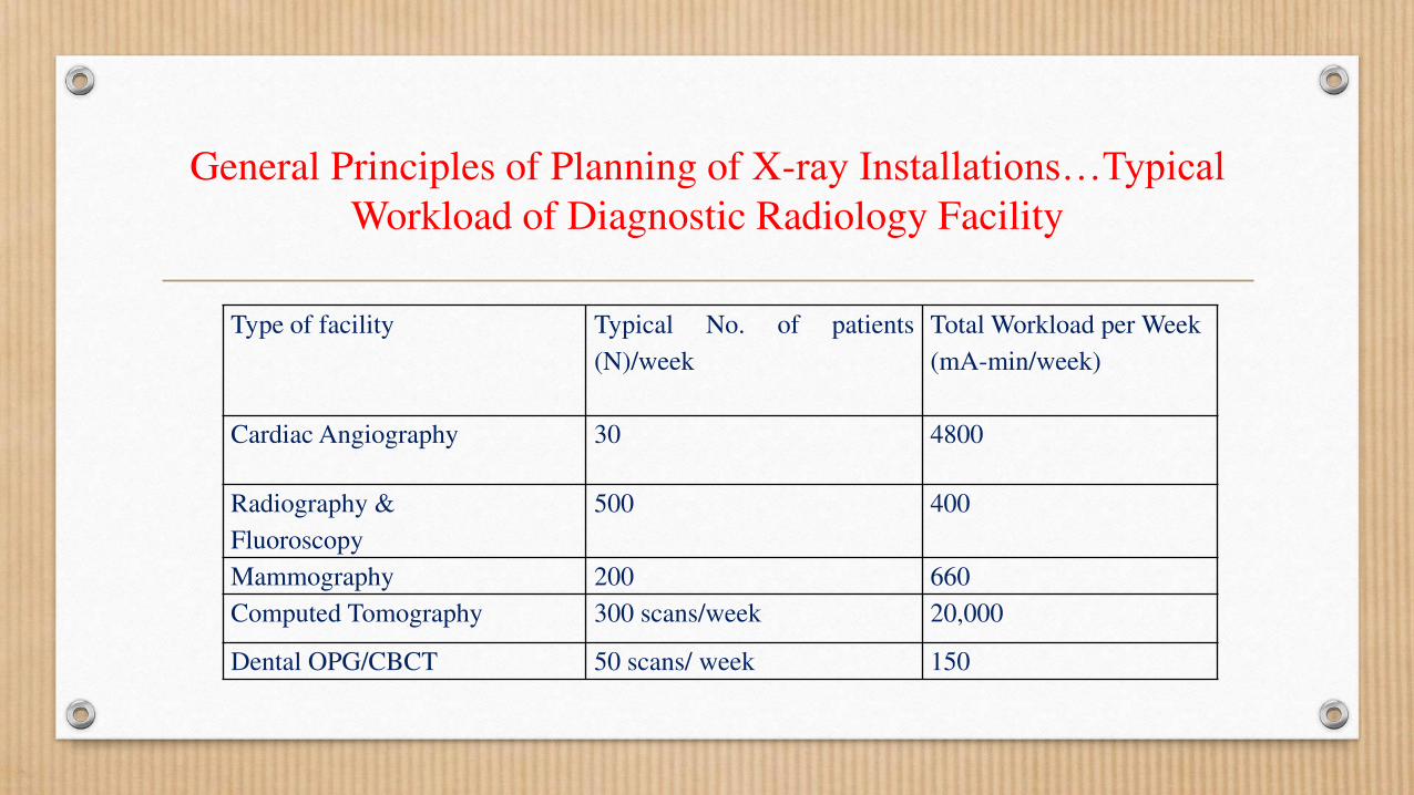
Type of facility Typical No. of patients
(N)/week
Total Workload per Week
(mA-min/week)
Cardiac Angiography 30 4800
Radiography &
Fluoroscopy
500 400
Mammography 200 660
Computed Tomography 300 scans/week 20,000
Dental OPG/CBCT 50 scans/ week 150
General Principles of Planning of X-ray Installations…Typical Workload of Diagnostic Radiology Facility
General Principles of Planning of X-ray Installations…
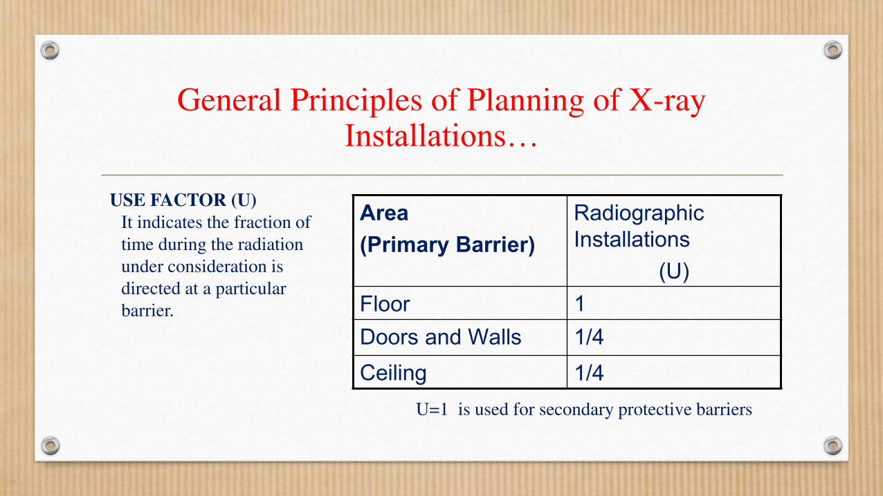
USE FACTOR (U)
It indicates the fraction of
time during the radiation
under consideration is
directed at a particular
barrier.
U=1 is used for secondary protective barriers
Area
(Primary Barrier)
Radiographic
Installations
(U)
Floor 1
Doors and Walls 1/4
Ceiling 1/4
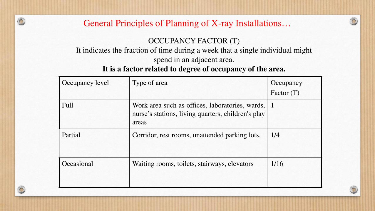
OCCUPANCY FACTOR (T)
It indicates the fraction of time during a week that a single individual might
spend in an adjacent area.
It is a factor related to degree of occupancy of the area.
Occupancy level Type of area Occupancy
Factor (T)
Full
Work area such as offices, laboratories, wards,
nurse’s stations, living quarters, children's play
areas
1
Partial Corridor, rest rooms, unattended parking lots. 1/4
Occasional Waiting rooms, toilets, stairways, elevators 1/16
General Principles of Planning of X-ray Installations…
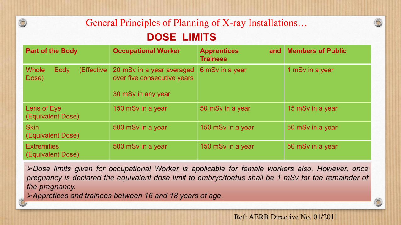
DOSE LIMITS
Part of the Body Occupational Worker Apprentices and
Trainees
Members of Public
Whole Body (Effective
Dose)
20 mSv in a year averaged
over five consecutive years
30 mSv in any year
6 mSv in a year 1 mSv in a year
Lens of Eye
(Equivalent Dose)
150 mSv in a year 50 mSv in a year 15 mSv in a year
Skin
(Equivalent Dose)
500 mSv in a year 150 mSv in a year 50 mSv in a year
Extremities
(Equivalent Dose)
500 mSv in a year 150 mSv in a year 50 mSv in a year
Dose limits given for occupational Worker is applicable for female workers also. However, once
pregnancy is declared the equivalent dose limit to embryo/foetus shall be 1 mSv for the remainder of
the pregnancy.
Appretices and trainees between 16 and 18 years of age.
Ref: AERB Directive No. 01/2011
General Principles of Planning of X-ray Installations…

General Principles of Planning of X-ray
Installations…
Shielding design goals (P) are practical values, for a single x-ray equipment, that are evaluated at a reference point beyond a protective barrier.
Controlled Areas: Controlled areas are those where x-ray equipment is used, such as x-ray procedure rooms and x-ray control room.
Recommended weekly shielding design goal (P) at control areas is 40 mR/week (20 mSv in a year).
The workers in these areas are primarily radiologists/related medical practitioners and x-ray technologists who are trained in the use of ionizing radiation and whose radiation exposure is individually monitored.
Uncontrolled Areas: Uncontrolled areas are those occupied by individuals such as visitors to the facility and employees who do not work routinely with or around radiation sources. Areas adjacent to but not part of the x-ray facility is called uncontrolled areas.
Recommended Weekly shielding design goal (P) at uncontrolled areas is 2 mR/week (1 mSv in a year).
Codal Requirements for Room Layout of X-ray Equipment
• The room housing an X-ray equipment shall have an appropriate area to facilitate easy movement of staff and proper patient positioning.
• Appropriate structural shielding shall be provided for walls, doors, ceiling and floor of the room housing the X-ray equipment so that radiation exposures received by workers and the members of the public are kept to the minimum and shall not exceed their respective dose limits.
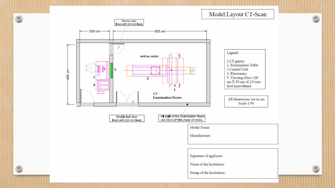
• The control console of computed tomography equipment shall be installed in a separate room located outside but adjoining to computed tomography room and provided with appropriate shielding, direct viewing and oral communication facilities between the operator and the patient.
• Interventional Radiology equipment room shall have an adjoining control room with appropriate facilities for shielding, direct viewing and oral communication facilities between the operator and the patient.
Codal Requirements for Room Layout of X-ray Equipment…
• In case of room housing radiography equipment, chest stand shall be located in X-ray room such that no significant stray radiation reaches at control console/entrance door/ areas of full time occupancy such that the dose limits to radiation worker and members of public are not exceeded.
• Mobile X-ray equipment, when used as fixed X-ray equipment, shall comply with all the requirements of those of fixed X-ray installation.
• Movement of mobile X-ray equipment shall be restricted within the institution for which it is registered.
• A permanent radiation warning symbol and instructions for pregnant/likely to be pregnant women shall be posted on the entrance door of the X-ray installation, illustrating that the equipment emits X-radiation when energized.
• X-ray equipment installed in a mobile vehicle, shall be provided with an appropriate shielding enclosure to ensure adequate built-in protection for persons likely to be present in and around the vehicle. Shielding shall be provided around the equipment from all the sides up to height of 2 m from external ground surface.
General Recommendations for Planning
• Room should have preferably one entrance door and window if present, should be above 2 m from the finished floor level outside the x-ray room.
• The protective screen (mobile protective barrier) should be at least 2 m high in height and of sufficient width to allow at least two persons stand behind the screen during exposure.
• The mobile protective barrier should have a viewing window with size 45 cm x 45 cm and centered 1.5 m above the finished floor.
• Floor-to-floor height (the vertical distance from the top of one floor to the top of the next floor) will range from 3 to 5 m. A conventional ceiling height of 2.4 m should be adequate for Dental and DEXA rooms.
• The x-ray room should not be a throughway to another room.
• The operator‘s console area should be located such that the operator has a clear panoramic view of the patient and radiation is scattered twice before entering the protective area.
A pragmatic approach to radiation shielding should be considered; it may be more prudent and possibly more cost effective to specify a consistent level of shielding in all boundaries in the room rather than specifying different levels of shielding in each boundary.
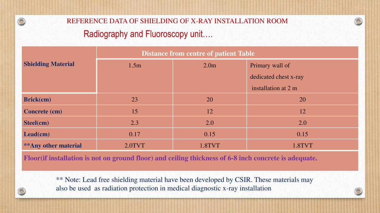
Radiography and Fluoroscopy unit…. REFERENCE DATA OF SHIELDING OF X-RAY INSTALLATION ROOM
** Note: Lead free shielding material have been developed by CSIR. These materials may
also be used as radiation protection in medical diagnostic x-ray installation
Shielding Material
Distance from centre of patient Table
1.5m 2.0m Primary wall of
dedicated chest x-ray
installation at 2 m
Brick(cm) 23 20 20
Concrete (cm) 15 12 12
Steel(cm) 2.3 2.0 2.0
Lead(cm) 0.17 0.15 0.15
**Any other material 2.0TVT 1.8TVT 1.8TVT
Floor(if installation is not on ground floor) and ceiling thickness of 6-8 inch concrete is adequate.
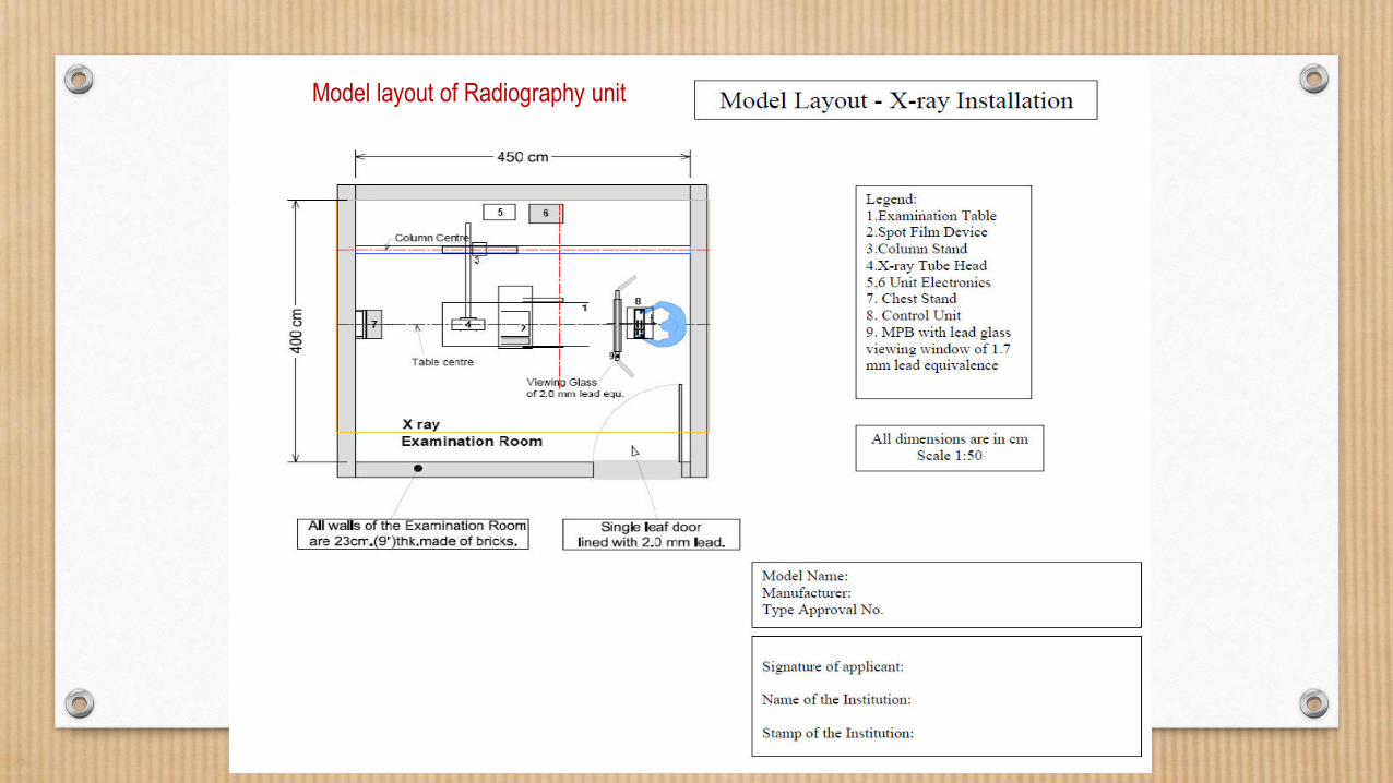
Model layout of Radiography unit
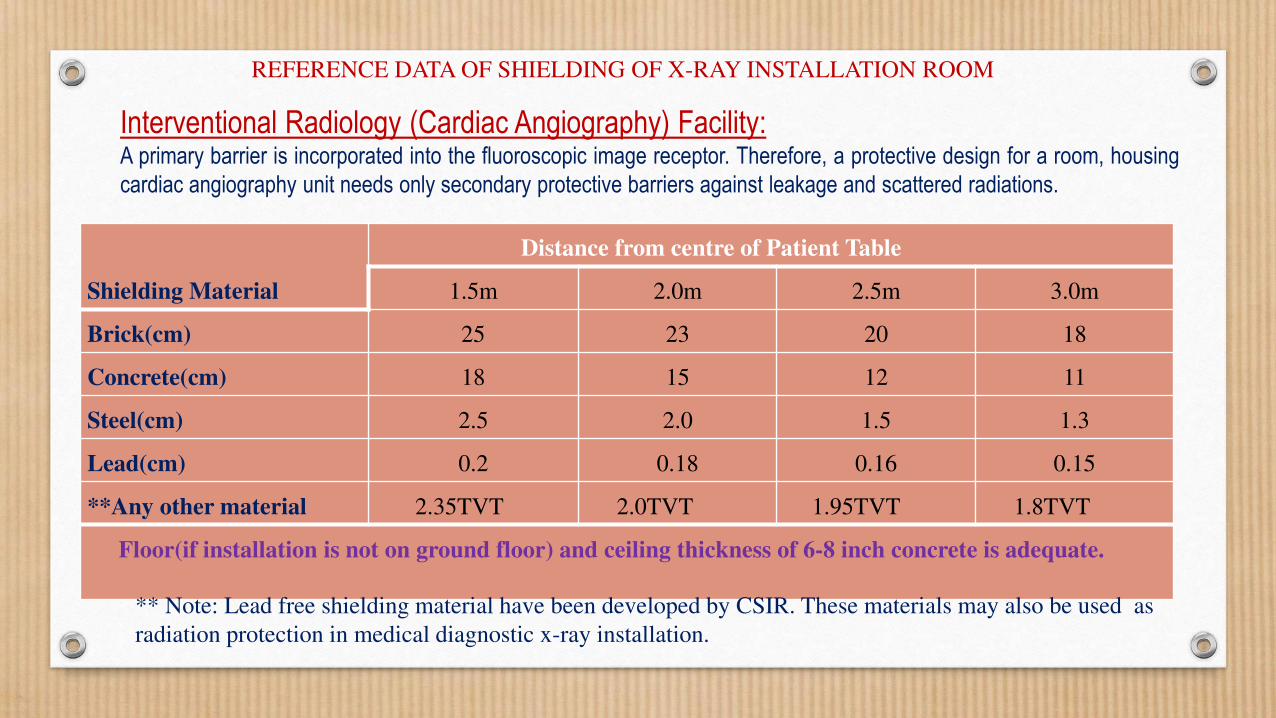
Interventional Radiology (Cardiac Angiography) Facility: A primary barrier is incorporated into the fluoroscopic image receptor. Therefore, a protective design for a room, housing
cardiac angiography unit needs only secondary protective barriers against leakage and scattered radiations.
Shielding Material
Distance from centre of Patient Table
1.5m 2.0m 2.5m 3.0m
Brick(cm) 25 23 20 18
Concrete(cm) 18 15 12 11
Steel(cm) 2.5 2.0 1.5 1.3
Lead(cm) 0.2 0.18 0.16 0.15
**Any other material 2.35TVT 2.0TVT 1.95TVT 1.8TVT
Floor(if installation is not on ground floor) and ceiling thickness of 6-8 inch concrete is adequate.
REFERENCE DATA OF SHIELDING OF X-RAY INSTALLATION ROOM
** Note: Lead free shielding material have been developed by CSIR. These materials may also be used as
radiation protection in medical diagnostic x-ray installation.
Name of Institute:
Complete Address
of Institute:
Make of X-ray
Equipment:
Model of X-ray
Equipment:
Signature of Head
of Institute:
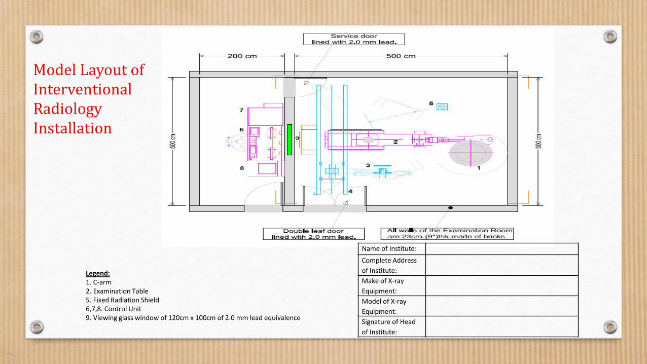
Legend:
1. C-arm
2. Examination Table
5. Fixed Radiation Shield
6,7,8. Control Unit
9. Viewing glass window of 120cm x 100cm of 2.0 mm lead equivalence
Model Layout of
Interventional
Radiology
Installation
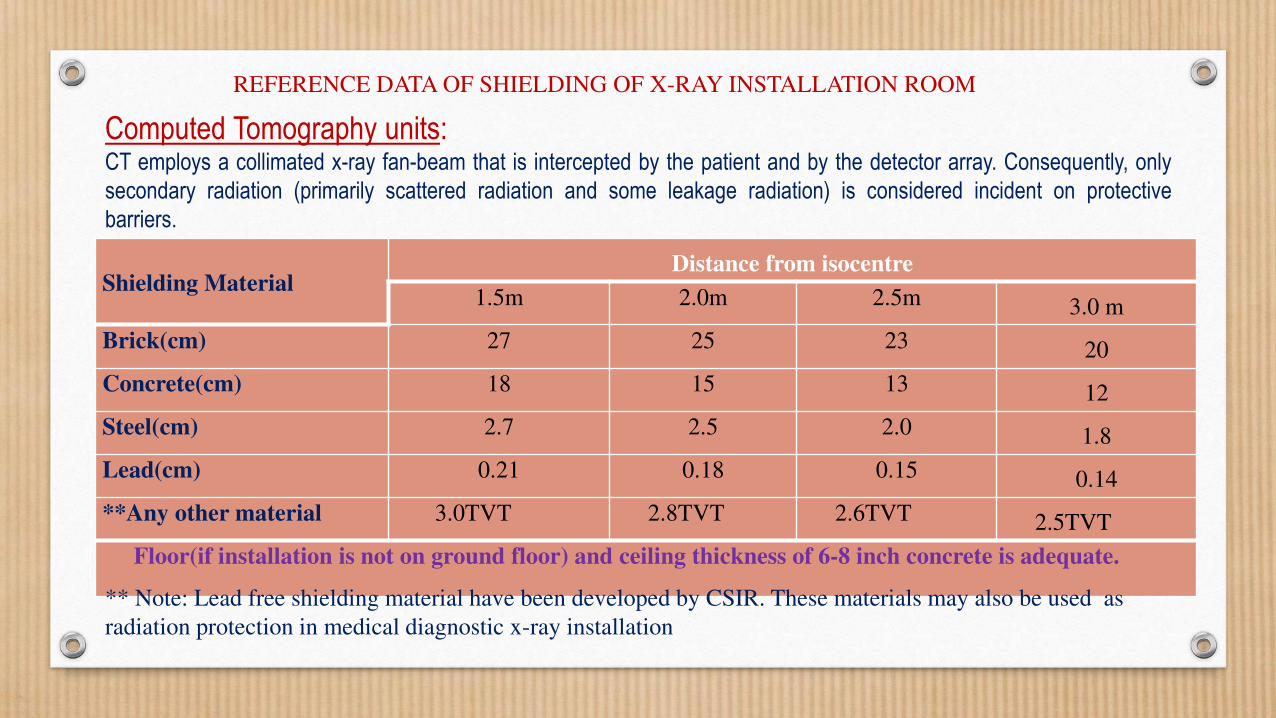
Computed Tomography units: CT employs a collimated x-ray fan-beam that is intercepted by the patient and by the detector array. Consequently, only
secondary radiation (primarily scattered radiation and some leakage radiation) is considered incident on protective
barriers.
Shielding Material Distance from isocentre
1.5m 2.0m 2.5m 3.0 m
Brick(cm) 27 25 23 20
Concrete(cm) 18 15 13 12
Steel(cm) 2.7 2.5 2.0 1.8
Lead(cm) 0.21 0.18 0.15 0.14
**Any other material 3.0TVT 2.8TVT 2.6TVT 2.5TVT
Floor(if installation is not on ground floor) and ceiling thickness of 6-8 inch concrete is adequate.
REFERENCE DATA OF SHIELDING OF X-RAY INSTALLATION ROOM
** Note: Lead free shielding material have been developed by CSIR. These materials may also be used as
radiation protection in medical diagnostic x-ray installation
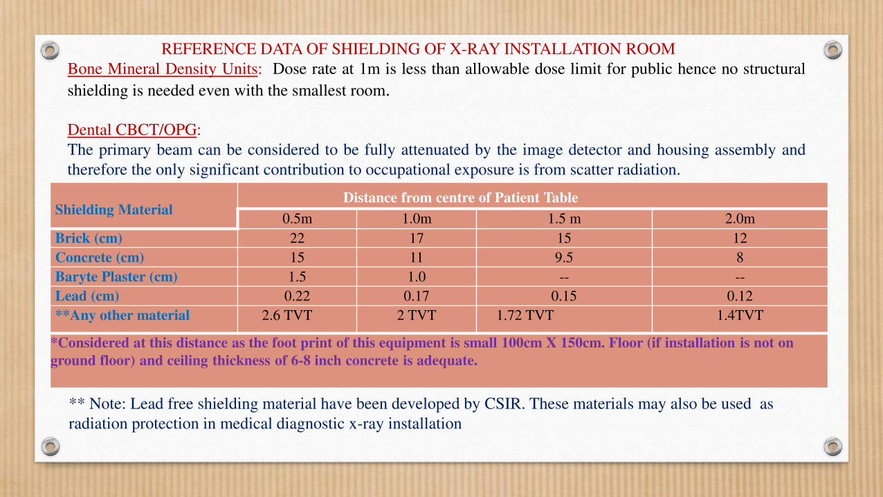
Bone Mineral Density Units: Dose rate at 1m is less than allowable dose limit for public hence no structural
shielding is needed even with the smallest room.
Dental CBCT/OPG:
The primary beam can be considered to be fully attenuated by the image detector and housing assembly and
therefore the only significant contribution to occupational exposure is from scatter radiation.
Shielding Material Distance from centre of Patient Table
0.5m 1.0m 1.5 m 2.0m
Brick (cm) 22 17 15 12
Concrete (cm) 15 11 9.5 8
Baryte Plaster (cm) 1.5 1.0 -- --
Lead (cm) 0.22 0.17 0.15 0.12
**Any other material 2.6 TVT 2 TVT 1.72 TVT 1.4TVT
*Considered at this distance as the foot print of this equipment is small 100cm X 150cm. Floor (if installation is not on
ground floor) and ceiling thickness of 6-8 inch concrete is adequate.
REFERENCE DATA OF SHIELDING OF X-RAY INSTALLATION ROOM
** Note: Lead free shielding material have been developed by CSIR. These materials may also be used as
radiation protection in medical diagnostic x-ray installation
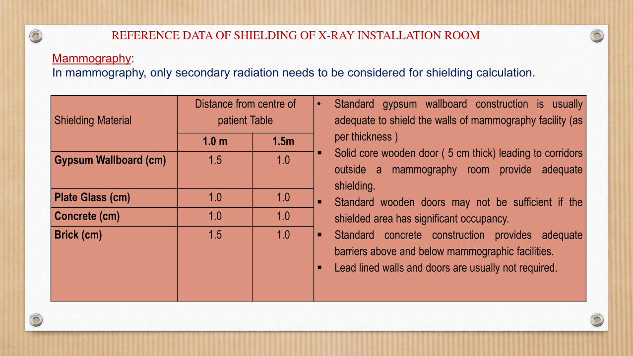
Mammography:
In mammography, only secondary radiation needs to be considered for shielding calculation.
Shielding Material
Distance from centre of
patient Table
• Standard gypsum wallboard construction is usually
adequate to shield the walls of mammography facility (as
per thickness )
Solid core wooden door ( 5 cm thick) leading to corridors
outside a mammography room provide adequate
shielding.
Standard wooden doors may not be sufficient if the
shielded area has significant occupancy.
Standard concrete construction provides adequate
barriers above and below mammographic facilities.
Lead lined walls and doors are usually not required.
1.0 m 1.5m
Gypsum Wallboard (cm) 1.5 1.0
Plate Glass (cm) 1.0 1.0
Concrete (cm) 1.0 1.0
Brick (cm) 1.5 1.0
REFERENCE DATA OF SHIELDING OF X-RAY INSTALLATION ROOM

Type of equipment:
Model Name:
Licence No.
X-RAY EXAMINATION IS GOING ON INSIDE, DO
NOT ENTER
PLEASE WAIT FOR YOUR TURN
DO NOT STAY INSIDE X-RAY ROOM, IF
REQUIRED TO ASSIST THE PATIENT, INSIST
FOR PROTECTIVE APRON!
Similar display shall be prepared in local/regional language
Format of warning sign to be pasted outside medical diagnostic x-ray installation
To be printed in appropriate size
WARNING PLACARD INDICATED BELOW SHALL BE POSTED OUTSIDE X-RAY
ROOM
Summary
• This presentation describes room design requirements and shielding recommendations for all modalities of diagnostic radiology equipment.
• It elaborates the technical factors governing the shielding thicknesses of different materials for various medical diagnostic X-ray installations.
• It will be helpful for the medical professionals associated with use of diagnostic X-ray equipment to understand room shielding requirements of various diagnostic X-ray modalities.
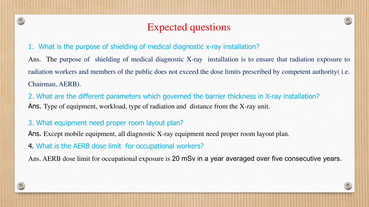
1. What is the purpose of shielding of medical diagnostic x-ray installation?
Ans. The purpose of shielding of medical diagnostic X-ray installation is to ensure that radiation exposure to
radiation workers and members of the public does not exceed the dose limits prescribed by competent authority( i.e.
Chairman, AERB).
2. What are the different parameters which governed the barrier thickness in X-ray installation?
Ans. Type of equipment, workload, type of radiation and distance from the X-ray unit.
3. What equipment need proper room layout plan?
Ans. Except mobile equipment, all diagnostic X-ray equipment need proper room layout plan.
4. What is the AERB dose limit for occupational workers?
Ans. AERB dose limit for occupational exposure is 20 mSv in a year averaged over five consecutive years.
Expected questions
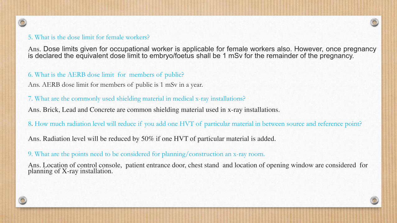
5. What is the dose limit for female workers?
Ans. Dose limits given for occupational worker is applicable for female workers also. However, once pregnancy is declared the equivalent dose limit to embryo/foetus shall be 1 mSv for the remainder of the pregnancy.
6. What is the AERB dose limit for members of public?
Ans. AERB dose limit for members of public is 1 mSv in a year.
7. What are the commonly used shielding material in medical x-ray installations?
Ans. Brick, Lead and Concrete are common shielding material used in x-ray installations.
8. How much radiation level will reduce if you add one HVT of particular material in between source and reference point?
Ans. Radiation level will be reduced by 50% if one HVT of particular material is added.
9. What are the points need to be considered for planning/construction an x-ray room.
Ans. Location of control console, patient entrance door, chest stand and location of opening window are considered for planning of X-ray installation.
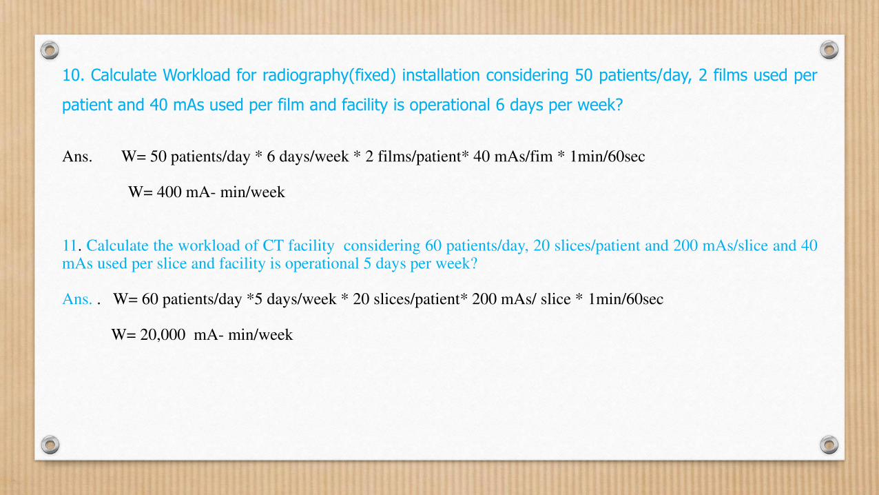
10. Calculate Workload for radiography(fixed) installation considering 50 patients/day, 2 films used per
patient and 40 mAs used per film and facility is operational 6 days per week?
Ans. W= 50 patients/day * 6 days/week * 2 films/patient* 40 mAs/fim * 1min/60sec W= 400 mA- min/week 11. Calculate the workload of CT facility considering 60 patients/day, 20 slices/patient and 200 mAs/slice and 40 mAs used per slice and facility is operational 5 days per week? Ans. . W= 60 patients/day *5 days/week * 20 slices/patient* 200 mAs/ slice * 1min/60sec W= 20,000 mA- min/week
References and sources for additional information
1. AERB SAFETY CODE NO.AERB/RF-MED/SC-3 (Rev. 2), RADIATION SAFETY IN MANUFACTURE,
SUPPLY AND USE OF MEDICAL DIAGNOSTIC X-RAY EQUIPMENT
2. Layout and Shielding Guidelines
(http://www.aerb.gov.in/AERBPortal/pages/English/t/XRay/forms/layout_guidelines.pdf)
3.National Council on Radiation Protection and Measurements, Report 147, Structural Shielding Design for
Medical X-Ray Imaging Facilities, NCRP, Bethesda, MD. 2004.
4. Radiation Shielding for Diagnostic radiology, 2nd Edition, Report of a BIR working party, D G Sutton et al,
2010.
List of presentations in the training Module
Basics of Diagnostic X-ray Equipment
Biological effects of Radiations
Medical X-ray imaging techniques
Planning of Diagnostic X-ray facilities
Quality Assurance of X-ray equipment
Quality Assurance of Computed Tomography equipment
Radiation Protection in Diagnostic Radiology Practice
Causes, prevention and investigation of excessive exposures in
diagnostic radiology
Regulatory Requirements for Diagnostic Radiology Practice
