search.jsp?r=19680011960 2018-11-17t13:43:04+00:00z · philco corporation aeronutronic division ......
TRANSCRIPT

NASA-SP- 5087
METALS, CERAMICS, AND
MATERIALS (TID -4500)
NASA-GEORGE C. MARSHALL SPACE FLIGHT CENTER
WE LDING OF PREC IPIT AT ION-HARDENING
STAINLESS STEELS
by
J. J. Vagi, R. M. Evans, and D. C. Martin
Prepared for
Manufacturing Engineering Laboratory
In Cooperation with
Technology Utilization Office
Under the Supervision of
Redstone Scientific Information Center
U. S. Army Missile Command
Redstone Arsenal, AlabamaMSFC Order No.
Report No. RSLC-598
Subcontracted to
Battelle Memorial Institute
Columbus Laboratories
505 King Avenue
Columbus, Ohio 43201
Contract No. DA-01-021-AMC-II651(Z)
!|
https://ntrs.nasa.gov/search.jsp?R=19680011960 2018-11-23T15:19:45+00:00Z

ABSTRACT
The state of the art of the welding of precipitation-hardening stainless
steels is reviewed. Welding preparations_ specific welding processes_ welding
dissimilar metals_ and joint quality are discussed.
I
=
ii

FOREWORD
Precipitation-hardening stainless steels are potentially use-
ful wherever corrosion resistance and high strength at high
temperatures are needed. They were developed initially to
meet urgent requirements in World War II, but new alloys and
methods of processing have since been introduced to assist
engineers concerned with missiles and space vehicles and with
various applications in the field of nuclear science and tech-
nology.
The Atomic Energy Commission and National Aeronautics
and Space Administration have established a cooperative pro-
gram to make available information, describing the technology
resulting from their research and development efforts, which
may have commercial application in American industry. This
publication is one of the many resulting from the cooperative
effort of these agencies to transfer technology to private in-
dustry.
This survey is based on information contained in a series of
reports originally prepared by Battelle Memorial Institute for
the Manufacturing Engineering Laboratory of the George C.
Marshall Space Flight Center. The original information has
been updated and revised in writing the current, seven volume
survey. These volumes were prepared under a contract with
the NASA Office of Technology Utilization which was moni-
tored by the Redstone Scientific Information Center.
iii

PREFACE
This report is one _f a series of state-of-the-art reports being prepared by
Battelle Memorial Institute, Columbus, Ohio, under Contract No. DA-01-021-AMC-
I1651(Z), in the general field of materials fabrication.
It reviews practices for joining precipitation-hardening stainless steels.
Discussions are presented to provide
(I) Information on joining preparations
(2) Information on joining processes
(3) Information on joint quality.
Techniques and special considerations that are normally followed when joining
these steels are described.
The information covered was obtained from producers of precipitation-
hardening stainless steels, equipment manufacturers, technical publications,
reports from Government contracts, and from interviews with engineers employed by
major fabricators and producers of these stainless steels. Data from reports and
memoranda issued by the Defense Metals Information Center also were used. Experi-
ence gained during the preparation of previous reports in the series has also
helped in the preparation of this report.
The literature search for this program began with 1955. In accumulating the
information necessary to prepare this report, the following sources within
Battelle were searched, covering the period January, 1955, to the present:
Defense Metals Information Center
Main Library
Slavic Library
iv

Technical Journal Indexes for the period of 1955 to the present also were searched
(Ref. i), and information was obtained from sources outside of Battelle, viz.,
the Redstone Scientific Information Center (Refs. 2 and 3), the Defense Documenta-
tion Center (Ref. 4), and the NASA Scientific and Technical Information Facility
(Ref. 5).
Personal contacts also were made with the following individuals and
organizations:
Air Reduction Company, Inc.
Airco Welding Products DivisionP. O. Box 486
Union, New Jersey 07083
A. N. Kugler
Allegheny Ludlum Steel Corporation
Oliver Building
Pittsburgh, Pennsylvania
G. Aggen
John Paulus
Doyle Smee
American Society for Metals
Metals Park, Ohio 44073
A. G. Gray
American Welding Society, Inc.
United Engineering Center345 East 47th Street
New York, New York 10017
Edward A. Fenton
AMF Beaird, Inc.
P. O. Box 1115
Shreveport, Louisiana
R. Melsenback
71100
Armco Steel Corporation
Baltimore, Maryland
Harry EspyJ. Junod
Armco Steel Corporation
Middletown, Ohio
G. E. Linnert
H. S. White
L. Looby
Astro Metallurgical Corporation
Wooster, Ohio
R. S. Emlong
Boeing Airplane Company
Seattle, Washington
A. M. Scroogs
Crucible Steel Company of America
P. O. Box 988
Pittsburgh, Pennsylvania 15230
E. J. Dulis
V. W. Thompson
Ford Motor Company
Philco Corporation
Aeronutronic Division
Ford Road
Newport Beach, California
A. J. Williams
92663
General Electric Company
Flight Propulsion Laboratory Dept.
Cincinnati 13, Ohio
W. A. Hutton
%,

Gregory Industries, Inc.Toledo Avenue and East 28th Street
Lorain, Ohio
R. C. Singleton
Grumman Aircraft Engineering Corporation
South Oyster Bay Road
Bethpage
Long Island, New York 11714
Hobart Technical Center
Hobart Brothers Company
Troy, Ohio
Howard CaryD. Conklin
Industrial Stainless Steel Corp.
Cambridge, Massachusetts
Edmund Malcolm
King Fifth Wheel Company
Mountaintop, Pennsylvania
A. S. Martin
J. Suchecki
Langley Research Center
Langley Station
Hampton, Virginia
Floyd L. Thompson, Director
Ling-Temco-Vought, Inc.P. O. Box 5003
Dallas, Texas 75222
A. L. Schoeni
Lockheed Aircraft Company
Missiles and Space Division
Sunnyvale, California
Glenn E. Faulkner
Cecil Kline
Richard E. Lewis
McDonnell Aircraft Corporation
Box 516
St. Louis, Missouri 63166
Edward J. Regan
Howard J. Siegel
Menasco Manufacturing Company
805 South Fernando Boulevard
Burbank, California 91503
Sumner Smith
Mills-Wolf Company
Bedford, Ohio
Don Wolf
National Aeronautics and
Space Administration
Lewis Research Center
Technical Information Center
21000 Brookpark Road
Cleveland, Ohio 44135
George Mandel, Assistant Chief
North American Aviation
Columbus Division
Columbus, Ohio
George Martin
Oak Ridge National Laboratory
P. O. Box X
Oak Ridge, Tennessee
Gerald M. Slaughter
Ryan Aeronautical Company
San Diego, California
Sciaky Brothers, Inc.
4915 West 67th Street
Chicago, lllinois 60638
William S. Rudin
Thermal-Dynamics Corporation
Lebanon, New Hampshire
Jim Browning
Union Carbide Corporation
Linde Division
686 Frelinghuysen Avenue
Newark, New Jersey 07114
Stanley P° Filipski
K° C. Linepensel
Ro L. O'Brien
vi

UnionCarbideCorporationStellite DivisionGeneralOfficeKokomo,Indiana
A. M. EdwardsE. G. Ridoux
United Aircraft CorporationHamilton StandardDivisionWindsorLocks, Connecticut
JohnW.Meier, Chief Engineer
United Aircraft CorporationPratt & WhitneyAircraft Division1400Main StreetEast Hartford, Connecticut 06118
JohnJ. MullinsF. L. MurphyF. T. Wells
United States ArmyTank-AutomotiveCenter
Materials LaboratoryHeadquartersWarren,Michigan
Joice O. Cox,Jr., ChiefVictor H. Pagano
Weldin_ Design and Fabrication812 Huron Road
Cleveland, Ohio 44115
R. N. Williams
Welding Engineer Publications, Inc.
5826 Dempster Street
Box 28
Morton Grove, Illinois 60053
T. B. Jefferson
The authors wish to thank each of these individuals and their organizations
for contributions. They also wish to thank Vernon W. Ellzey and John A. Gibson
of Battelle, Project Technical Coordinators, and D. Hauser, H° W. Mishler, and
H. E. Pattee, who contributed to this report.
vii

TABLE OF CONTENTS
INTRODUCTION ................................
MATERIALS ................................
Types, Heat Treatment, Properties .................
Welding Filler Wires ........................
Material Condition for Joining ...................
Joint Preparation .........................
Plasma-Arc Cutting ......................
DISTORTION CONTROL AND TOOLING ......................
Distortion Control by Reduction of Shrinkage Forces ........
Distortion Control by Offsetting Parts and
Balancing Shrinkage Forces .....................
Distortion Control by Tack Welding and Jigging ...........
Tack Welding .........................
Jigging ............................
JOINING PROCESSES ............................
Fusion Welding ...........................
Shielded Metal-Arc Welding ...................
Gas Tungsten-Arc Welding ....................
Gas Metal-Arc Welding .....................
Submerged-Arc Welding .....................
Plasma-Arc Welding .......................
Electron-Beam Welding .....................
Resistance Spot Welding ....................
Resistance Seam Welding ....................
Flash Welding . ........................
Joint Design and Joint Preparation ...............
Other Resistance Welding Processes .............
Solid-State Welding .........................
Diffusion Welding ..........................
Deformation Welding .........................
Pa_e
i
i
3
3
4
ii
15
19
21
25
27
27
28
28
32
33
36
40
59
75
78
79
86
107
109
III
114
120
120
124
viii

TABLE OF CONTENTS
(Continued)
Brazing ..............................
Applications ............................
JOINT QUALITY ..............................
Inspection .............................
Defects ..............................
Porosity ...........................
Defects in Resistance Welds ....................
DISSIMILAR METALS ............................
CONCLUSIONS AND RECOMMENDATIONS .....................
APPENDIX A - WELDING PROCESSES .....................
Shielded Metal-Arc Welding .....................
Gas Tungsten-Arc Welding ......................
Gas Metal-Arc Welding .......................
Submerged-Arc Welding .......................
Plasma-Arc Welding .........................
Electron-Beam Welding .......................
Resistance Spot, Seam and Projection Welding ............
Flash Welding ...........................
Brazing ..............................
Solid-State Welding ........................
Diffusion Welding .......................
Deformation Welding ......................
REFERENCES ...............................
Page
127
132
137
143
143
144
144
]46
155
159
160
160
163
163
163
166
168
168
172
172
174
174
175
ix
Figure
i.
2.
_o
4.
5.
6.
7.
8°
9.
I0.
II.
12.
13.
14.
15.
16.
17.
18.
19.
20.
21.
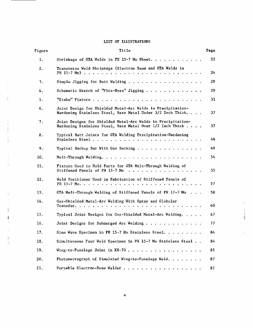
LIST OF ILLUSTRATIONS
Title Page
Shrinkage of GTA Welds in PH 15-7 Mo Sheet ............ 22
Transverse Weld Shrinkage (Electron Beam and GTA Welds in
PH 15-7 Mo) ........................... 24
Simple Jigging for Butt Welding ................. 29
Schematic Sketch of '_ire-Hose" Jigging ............. 29
"Stake" Fixture ......................... 31
Joint Design for Shielded Metal-Arc Welds in Precipitation-
Hardening Stainless Steel, Base Metal Under 1/2 Inch Thick .... 37
Joint Designs for Shielded Metal-Arc Welds in Precipitation-
Hardening Stainless Steel, Base Metal Over 1/2 Inch Thick .... 37
Typical Butt Joints for GTA Welding Precipitation-HardeningStainless Steel ......................... 46
Typical Backup Bar With Gas Backing ............... 49
Melt-Through Welding ....................... 54
Fixture Used to Hold Parts for GTA Melt-Through Welding of
Stiffened Panels of PH 15-7 Mo ................. 55
Weld Positioner Used in Fabrication of Stiffened Panels of
PH 15-7 Mo ............................ 57
GTA Melt-Through Welding of Stiffened Panels of PH 17-7 Mo 58
Gas-Shielded Metal-Arc Welding With Spray and Globular
Transfer ............................. 60
Typical Joint Designs for Gas-Shielded Metal-Arc Welding ..... 67
Joint Designs for Submerged Arc Welding ............. 77
Sine Wave Specimen in PH 15-7 Mo Stainless Steel ......... 84
Simultaneous Four Weld Specimen in PH 15-7 Mo Stainless Steel . 84
Wing-to-Fuselage Joint in XB-70 ................. 85
Photomacrograph of Simulated Wing-to-Fuselage Weld ........ 87
Portable Electron-Beam Welder .................. 87
X

Figure
22.
23.
24.
25.
26.
27.
28.
29.
30.
31.
32.
33.
34.
35.
36.
37.
38.
39.
LIST OF ILLUSTRATIONS
(Continued)
Title Page
Portable Electron-Beam Welder Setup for Overhead
Welding of Large Parts ..................... 88
Electron-Beam Welded Pressure Vessel .............. 89
Tensile Shear Strength at Elevated Temperatures for Spot
Welded AM-350 Stainless Steel .................. 94
Strap Hinge of AM-350 Used to Fasten Canisters of DelicateInstruments in the Atlas Missile ................ 95
Wrapping AM-355 Foil Onto a Mandrel Where it is Tack Welded
into Position Prior to Spot Welding ............... 97
Resistance Spot Welding a New AM-355 Case ........... 98
Tension Shear Strengths for Spot Welds in O.060-1nch-ThickAlmar 363 ............................ 99
Almar 363 Structural Members Being Spot Welded to Type 201
Stainless Steel Panels ..................... I00
Spot Welding Economically Fabricates a Lightweight High-
Strength Aircraft Part Made of 17-7 PH Precipitation-HardeningStainless Steel ......................... 103
Machine Arrangement for Series Seam Welding ........... II0
Transformer Capacity Versus Weld Area for Flash Welding .... 112
Maximum Machine Upset-Pressure Requirements Versus Weld
Area for Flash Welding ..................... 112
Total Metal Allowance Versus Stock Thickness for Flash
Welding ............................. 113
Illustration of a Flash-Welded Jet Engine Ring ......... 116
Processing Steps for Fabricating Flash-Welded Jet Engine
Rings .............................. 117
Exploded View of Pack Assembly for Producing Roll-Welded
Vertical-Rib Sandwich Panels from PH 14-8 Mo .......... 126
Retort and Tooling for Brazing 17-7 PH Precipitation-
Hardening Stainless Steel Honeycomb ............... 134
Assembly of Panel for XB-70 Prior to Brazing Includes Silver-
Brazing Alloy_ Honeycomb Core of PH 15-7 Mo Precipitation-
Hardening Stainless Steel_ Facing Sheets and Edge Members. 135
xi

Figure
40.
41.
42.
43.
44.
45.
46.
47.
48.
49.
50.
LISTOFILLUSTRATIONS(Continued)
Title
Size andContourof Various HoneycombSandwichParts MadeforXB-70Are Illustrated by TheseCeramicFacesfor ElectricBlanket Brazing ........................
Hydraulic Valve Fabricated by BrazingAM-355Precipitation-HardeningStainless Steel Bodyto TubingSegmentsof AM-350Steel..............................
BrazedJoints for Aircraft Hydraulic Systems..........
BrazedJoint for B-70HYdraulic System,Illustrating ToolingUsedDuringBrazing.......................
Missile AssemblyUsedWith RedFumingNitric Acid........
TheseTubesare About20 Inches Longand8 Inches in DiameterWith a Wire Helix Extending the Lengthof the Tube.......
Arc WeldDefects ........................
ConwaonDefects in ResistanceSpot andSeamWeldsandTheirCauses.............................
Incipient Melting and Central Cracksin SpotWeldedA-286Alloy Sheets ..........................
Electron-BeamWeldedBimetal TurbineWheel...........
Nomographfor Finding the Changein Diametral ClearanceinJoints of Dissimilar Metals for a Variety of BrazingSitutations ...........................
Page
136
138
139
140
141
142
145
147
149
151
152
A-I
A-2
A-3
A=4
A-5
A-6
A-7
Sketchof Shield-Metal-Arc WeldingOperation ..........
Sketchof a GasTungsten-ArcWeldingSystem .........
Sketchof a GasMetal-ArcWeldingSystem............
Sketchof a Submerged-ArcWeldingOperation...........
Sketchof Plasma-ArcTorchand System..............
SketchesShowingTwoTypesof Electron-BeamWeldingMachines.
SketchShowingElectrical Flow andHeatGenerationin SpotWeld ..............................
161
162
164
165
167
169
170
xii

Figure
A-8
A-9
LIST OF ILLUSTRATIONS
(Continued)
Title
Sketches Showing Characteristics of Spot, Seam, and Projection
Welding .............................
Sketch Showing Basic Characteristics of Flash-Welding Process .
Page
171
173
Table
I.
II.
III.
IV.
Vo
VI.
VII.
VIII.
IX.
X.
XI.
XII.
XIII.
XIV.
XV.
LIST OF TABLES
Title
Compositions of Commercial Precipitation-Hardening StainlessSteels ......................... ....
Forms in Which the Precipitation-Hardening Stainless Steels
are Available ..........................
Heat Treatments Used With Commercial Precipitation-Hardening
Stainless Steels .........................
Properties of Commercial Precipitation-Hardening Stainless
Steels ..............................
Electrodes Recommended for Welding Precipitation-Hardening
Stainless Steels .........................
Typical Sequence of Procedures for Pickling Precipitation-
Hardening Stainless Steels ....................
Compositions of Electrolytic Pickling Solutions for Various
Steels ..............................
Preferred Base Metal Condition for Joining ............
Plasma-Arc Cutting Conditions for Type 304 Stainless Steel.
Process Selection Chart for Welding Precipitation-Hardenable
Stainless Steels .........................
Suggested Welding Conditions for Shielded-Metal-Arc Welding of
Precipitation-Hardening Steels ..................
Recommended Current Ranges for Tungsten and Thoriated Tungsten
Electrodes ............................
Conditions for Gas-Tungsten-Arc Welding Precipitation-Hardening
Stainless Steels .........................
Dimensions for Tooling for GTA Welding PH 15-7 Mo Sheet .....
Welding Current Required to Achieve Spray Transfer ........
Page
12
16
17
18
20
34
39
42
47
51
65
xiii

Table
XVI
XVII
XVIII
XIX.
XX,
XXI.
XXII.
XXIII.
XXIV.
KEY°
XXVI
XXVII
XXVIII
XXIX
XXX°
XXXI
LIST OF TABLES
(Continued)
Title
Electrode Wire Size for GMA Welding Various Thicknesses of
Precipitation-Hardening Stainless Steel .............
Plasma-Arc Welding Conditions for Square Butt Joints in Type
304 Stainless Steel .......................
Typical Conditions for Electron-Beam Welding Precipitation-
Hardening Stainless Steels ...................
Tension-Shear Strengths of Spot-Welded AM-350 and AM-355
Stainless Steels ........................
Effect of Heat Treatment on Tension-to-Shear Ratios of Spot-
Welded 0.080-1nch-Thick AM-350 Stainless Steel .........
Resistance Spot Welding Conditions andProperties of Spot
Welds in 17-7 PH Precipitation-Hardening Stainless Steel ....
Spot Welding Schedule for O.025/0.025-1nch PH 14-8 Mo
Stainless Steel .........................
Properties of Spot Welds in PH 15-7 Mo .............
Resistance-Spot-Welding Conditions and Properties of Spot Welds
in A-286 Precipitation-Hardening Stainless Steel ........
Welding Conditions and Properties for Resistance Seam Welds in
17-7 PH Precipitation-Hardening Stainless Steel .........
Properties of Flash Welds in Precipitation-Hardening Stainless
Steels .............................
Tensile Strength of Resistance Projection Welded Cross Wire
Joints ...........................
Sun_nary of Diffusion Welding Processes for Precipitation-
Hardening Stainless Steels ...................
Con_monly Used Noble Metal Brazing Alloys for Precipitation-
Hardening Stainless Steels ...................
Commonly Used Nickel-Base Brazing Alloys for Precipitation-
Hardening Stainless Steels ...................
Coefficient of Thermal Expansion of Some Common Alloys .....
Page
66
79
82
93
93
I01
104
105
106
108
i15
119
123
129
131
154
xiv
WELDING OF PRECIPITATION-HARDENINGSTAINLESS STEELS
SUMMARY
The preclpitation-hardening stainless steels can be welded by many of the
familiar welding processes. Because of the cost of these materials and the critical
uses to which they are applied, more care is usually taken in joining than with
carbon steels. All of these steels are hardenable by heat treatment. Therefore,
it is important that proper filler metals be used if it is intended that the welds
have the same heat-treatment response as the base material. It is important also
that good cleaning procedures be used to prevent contamination of the weld and the
heat-affected zone.
The precipitation-hardening stainless steel alloys can be divided into three
types: martensitic, semiaustenitic, and austenitic. Little difficulty is experi-
enced in welding the martensitic and semiaustenitic types. However, the use of
joining processes such as gas tungsten-arc or gas metal-arc, which may depend on
melting metal of the same composition as the base material should be avoided when
the austenitic types are joined.
In general, welding of the precipitatlon-hardening stainless steels is
similar to the more common nonhardenable austenitic stainless steels. When proper
techniques are used, joints of excellent quality and high strength can be produced
in the precipitation-hardening alloys.
INTRODUCTION
The precipitation-hardening stainless steels were developed during World
War II as the result of a need for stronger corrosion-resistant materials than
were then available. Knowledge of their properties became available generally
between 1946 and 1948 but new alloys and improved heat treatments continued to

appearat least until the late 1950s. Newermodifications of the original alloys,
usually developedfor particular applications, continue to appearperiodically.
Thewelding metallurgy of these alloys is discussedby Linnert andHarkins
(Refs. 6 and 7).
This report sum_narizesthe information on joining of precipitation-hardening
stainless steels that has becomeavailable since 1955. In it, the subject is
discussedvery briefly from the viewpoint of the materials themselvesandmuch
moreextensively from the viewpoint of joining processesand their applications
to theseparticular materials. Individual joining processes, dissimilar alloy
joining, and those special considerations whichmustbe takenwhenjoining the
various alloys are described. Inspection techniquesand the effects of defects
are also described.
Theprecipitation-hardening stainless steels are used in applications where
both high strength and resistance to corrosion or oxidation are desired. They
havebeenusedextensively in the aircraft industry for at least ten years.
Thereare also manyapplications of these steels to boosters andmissile systems.
Thesteels havemanyattributes whichmakethemdesirable in a wide variety of
structures and components.Theprecipitation-hardening stainless steels maintain
both oxidation resistance and strength to relatively high temperatures. They
are amongthe most fabricable of the high-strength materials. Theycan beworked
by most conventionalmethodssuchas rolling, machining,or forging whenin a quite
low strength condition and then hardenedby modestheat treatments subsequentto
working. With the exception of the austenitie precipitation-hardening alloys
these steels also havegoodweldability. Most of the co_mmonwelding processes
and a numberof other joining processesare usable with these steels. In general,
the precautions whichhave to be taken during welding are no moredifficult than
thosewhich are required for the commonnonhardenableaustenitic stainless steels.
Theprecipitation-hardening stainless steels are relatively high cost and
usedwherea high degreeof reliability is needed. Therefore, it is often2

necessaryto chooseprocessesandprocedures(shielded metal-arc, electron-beam,
brazing) which lead to the production of high-quality joints andminimize scrap
losses. Since the corrosion resistance of these steels is one of their major
attractions it is necessaryto be sure that the joining proceduresdo not detract
from this property. Thestrength of these steels is obtained throughheat treat-
ment. The final heat treatments are such that they canbe carried out either
during or after the joining operation. However,to obtain optimumproperties, it
is important that the recommendedheat-treating proceduresbe adheredto.
MATERIALS
Theprecipitation-hardening stainless steels, whenproperly heat treated,
havegoodcorrosion andoxidation resistance and fracture toughnessin addition
to high strength. Theyalso havegoodproperties at moderatelyhigh temperatures,
1300F for someof the types available.
TYPES,HEATTREATMENT,PROPERTIES
Theprecipitation-hardening stainless steels are groupedinto three types
(Ref. 7):
(I) Martensitic
(2) Semiaustenitic
(3) Austenitic.
This classification is basedon the behavior of the steel whenit is cooled from
an appropriate austenitizing (solution treating) temperature.
In martensitic types the austenite transforms to martensite on cooling.
This transformation causes some hardening. Additional strength is obtained by
aging at the proper temperature.
After cooling from the austenitizing temperature to room temperature the
semiaustenitic types remain austenitic. Reheating to an appropriate temperature
conditions the austenite so that it transforms to martensite on cooling to room
3

temperatureor lower. Subsequentaging at proper temperatureincreasesstrength
over that obtained by the austenite-martensite transformation.
Theaustenitic types donot transform on cooling to roomtemperature.
Strengtheningis obtained by aging the austenitic structure at an appropriate
temperature.
A thoroughknowledgeof the specific strengthening treatment applicable to
the particular precipitation-hardening alloy being fabricated is neededin order
to attain the full potential of the alloy. Weldingproceduresmust be adaptedto
these treatments in sucha waythat loss of strength is minimizedor that subse-
quent strengthening is possible.
For reader convenience,Table I showsthe compositionsof a numberof preci-
pitation-hardening stainless steels. Table II gives someidea of the forms in
which these steels can be obtained. Table III showsthe heat treatmentsused to
producedifferent properties in these steels. Thereasonsfor the difference and
numberof heat treatments is complex. It hasbeentreated in somedetail by
LudwlgsonandHall (Ref. 8). Theproperties of the various steels in various
conditions of heat treatment are given in Table IV.
WELDINGFILLERWIRES
For the fusion-welding processes, filler wires having the samecomposition
as the baseplate are generally used for welding the martensitie and semiaustenitic
steels to themselves. Weldsbetweenthese materials andother metals, suchas
nickel-base alloys, are usually madewith stainless steel filler wires of the
300 class. Coatedelectrodes can only be usedwith thosematerials whichdo not
contain aluminumor titanium if the weld is expectedto respondto heat treatment.
Theaustenitic types of precipitation-hardening steels are usually considered
to be nonweldableby fusion-welding processes. Whenthey are welded, filler wires
developedfor this purposeandhaving quite different compositionthan the base
4

,"-4
EI=M
q}
v
E--,
_cJ
zI-I
I
I-I
l--I
I--Irj
I.-.4
U
0
ZoI-I
E-'F-I
0
rj
A
.LJ
U
0.,-I.LJ
°,-I
0
E0
rj
_o
;0
0
II
• ''_'_ E.___II_0
IIIII IIIIII I
x
l_ l 'l I I II I I I I
0
t_l
E'_I 0 0 _'_ _'_ 0
"" ' I I I I I
"_,1 ,d_4._,_ ..1:
_1 o_ o
I I
x _
_0000_
XXXX X
0000_
_0000 0
_o_Il I{f{f
0_
Jill
O0
.°
fill
IIll
IIII
x_
O000_
O_00_
00_
0
_I0_
0
I0,-q
0 o_ O-I
I I
I I_'_ I I
00 X
_oo
00
0 •
I O0
I
_DO

TABLE II. FORMS IN WHICH THE PRECIPITATION-HARDENING STAINLESS
STEELS ARE AVAILABLE (Refs. 9,10_ ii, 12_ 13,14_ 15, 16)
Alloy Forms Available
Stainless W
17-4 PH
15-5 PH
414 Ti
ALMAR 362
ALMAR 363
17-7 PH
PH 15-7 Mo
AM 350
AM 355
A 286
17-10 P
HNM
Martensitic Types
Sheet, plate, bar
Sheet, strip, plate, bar, wire, castings, forgings
Sheet, strip, plate, bar, wire, forgings (heavy
sections in plate and bar not recommended)
Sheet, strip
Bars, hollow bars, wire, billets
Sheet, strip
Semiaustenitic Types
Sheet, strip, plate, bar, wire, forgings (heavy
sections in plate and bar not recormmended)
Plate, bar, wire, billets
Sheet, strip, foil, welded tubing, bar, wire
Sheet, strip, bars, castings, forgings
Austenitic Types
Sheet, strip, plate, bar, wire, billets, tubing
Plate, bar, wire, billets
Plate, bar, billets

o_
o;
co
v
E-_E_
r_
_U
r_
h_
Z
i
ZO
E_
CD
H
O
ED
H
P_c_
U_
Z
E_
h-I
_U
O
CO•r-I ,
4
_JC_
E4.
[-
"C
C
C
O
O
IO
_OO_OOO_
fill
u) c,4 o'_
r_
C C
0 0
0r_ r_
0 _ 0
,'_ ,..4 C_ o.
0
0 _J
-_
O_
0r-- 0
0
o
_ 0
I !
C
0
OED
O
I11
0t14
_ j0 ,._
O
0 u'_u,_ O0
0 0 ,._0 0
!
0
0,._ 0
_ _ 0 0,_
_ 0,-_
0 u_ .,_
p.,
_ _0_ 0
0 _ _ O_ 00 _ 0
0 0 0._
O0 NO
_0 _
-_ _0
_>_.._ 0"1 ,.--_ _ _q-_,--_ c_ O O,-_
"_ _ O _ '_ r._•,-i ._ o 0
_,_ _ _u'_
Oo_ J o_
Ou_O O_O O
O r-- r-, O t--
C,
OOO
O
O0
i
7

Q}
.r-I
0
v
HI--I
0 0• pI -_
_4
I
I
I
e-,
o
,,.-4 _ _
COlQJI
[..-I I
.._1
"_1Oil
0
0N
r-4
_.) "0
_J _J
0 U 0
..C: ..C: ..C: _ ,.C:
0 0 0 0
._ _-_ F.r._ F-_I-I
m O0 0 0
e_l 0 0 I1-I mr'_ ! 0"3 ¢¢3 I ¢__-4 ! _-d _.4 ! ,--I
1_ 0" I-I
O0
I.-,
_ _ 000U,_
000
o0000
..c:_J
0
0O0 _-a
0
0{.}
0
0 4J

'4-1
v
r._E-,
O_
ZI-I
;m
I
oI--4
I--I0
)o
I-4E_
I.-I
0
0 _J ,_4
.,,...I,-I 4-1',0_ _0
0 ,-4
0 .,.4 _)
_0 ._0 _
4.1
_.,_ _000>-4 _0
_i ,-4
QIlq
.,.4
0
1.1
0
>,0
p_<t
I 0
I I
I I
0
0 _ u"% t._ u"_ 0 _ 0%
...... ! |O0 O0 O0 O0 O0 0'_ _ I
0
I _ _ _ _ 0
W
>
0
.,-4.i-I
.,.4 O_
0
!
,5
XIll
ffl'
(_1 ,iI ,.--I ,.-4 ,--I ,--I
O_
0 0000 000
> o >
0 0_ _ W0 0_ _ _
000 000
• ., .,°|
_00 0_0_ 0_
0_ 00_0_ _
• _ 000
>>> >>>000 000
-M°M._.M.M.M
000 000
000 000
666 6_6
i2i IXI
0 0
_00 _000_0 0_0
0
%O ,4D
,4 "a" U'_ _ _ m- ,--_
I I _ _ I
III IIIIIII IIII
II IIIIII IIII
_0_ _0_
_0 _00
_ _00_ _
°_._-_._-_._._
• •
0 u%
I

0
v
I0
coc0
co o O_
0_-_
0,,-4•T.4 0J
0
40
_-_ bD
14-.I.rq _ 00 0 _-_ _0oq 4-1 ,-i
• ,_ ._
•_ _o_ _ _0
"0
o-,-..I4-1.,-I
0_D
0
(_1
[.-.t!
._1
0J!
00
00
_o00
I
_0oo o
O0
_'q eq
u_oeq c_
oo
0
o_
0
oo_ ...I"
00
o 00 0
0OD
o
00
o
!

metal are used. When filler wires of the same composition as the base plate are
used, serious weld-metal cracking may occur.
Table V shows the filler wire recommended for use with the various steels.
MATERIAL CONDITION FOR WELDING
Production of satisfactory joints in any material depends on proper selection
of joining method, on proper joint design, and on proper cleaning of the material
prior to making the joint. In some materials, including the precipitation-
hardening stainless steels, satisfactory joints also depend on the material being
in the proper metallurgical condition prior to joining and proper treatment of
the material after joining. Choice of process and joint design will be discussed
in following sections of this report. Prewelding condition and postweld condi-
tioning will also be discussed.
It is necessary to be sure that corrosion and oxidation resistance of these
alloys are not lowered during fabrication operations. Corrosion resistance can
be seriously affected by contamination during joining or heat-treating operations
of either base metal or weld metal by dirt, oils, grease, crayon marks, etc. on
the surface (Ref. 17). Carbon pickup from surface contaminants can adversely
affect heat-treatment response as well as corrosion resistance. Sulfur pickup
can affect both corrosion resistance and properties. Other materials can affect
various properties adversely. Consequently, the surfaces of all parts must be
clean before joining or heat treatment is undertaken.
Dirt and films of oil and grease can be removed by washing or by degreasing
operations. Soaps can be removed with hot water. Removal of soluble oils,
tallow and fats require a hot alkaline solution wash followed by a hot water
rinse.
Oxide films of two types are encountered on precipitation-hardening stainless
steels (Refs. 9,10,11,14). Light oxide films are produced by the aging or
Ii

TABLEV. ELECTRODESRECOMMENDEDFORWELDINGPRECIPITATION-HARDENINGSTAINLESSSTEELS(Refs. 7,9,10,11,12,14,16,18)
Alloy CoatedElectrodes Filler Wires Dissimilar Joints
Martensitic Types
Stainless W Timken 16-25-6 A-286 Hastelloy W (a)
Timken 16-25-6 Hastelloy W Type 309(b)
17-4 PH W 17-4 PH W 17-4 PH Type 309(d)
Type 308 (c) Type 308 Type 309 Cb(d)
15-5 PH W 17-4 PH W 17-4 PH Type 309
Type 308 Type 308 Type 309 Cb
414 Ti Type 308, Type 309 414 Ti Type 309
ALMAR 362 Type 308, Type 309 AI/4AR 362(e) --
ALMAR 363 Type 308, Type 309 AI24AR 363 --
17-7 PH
PH 15-7 Mo
AM 350 and
AM 355
Semiaustenitic Types
W 17-4 PH, Type 308 W 17-7 PH
Type 309 W 13-9 PH(f)
Type 308, Type 309
AM 355
Type 308
Type 309
Type 310
WPH 15-7 Mo (sheet)
WPH 13-7 Mo (plate)_i#''
AM 350
AM 355
Type 310(g)Inco Weld A(h)
Inconel 82(h)
Type 310
Type 309
Type 308
Type 309
A 286
17-10 P
HNM
Type 309
Type 310
Austenitic Types
Inco 92
Hastelloy W
Arc welding not recommended.
Arc welding not recommended.
Type 309
Type 310
12

Footnotes for Table V
(a)
(b)
(c)
(d)
(e)
(f)
(g)
(h)
(i)
Nickel-base electrode or filler wire corresponding to American Welding Society
E NiCr-I or ER NiCrFe-7. In general, when electrodes or filler wires are
used whose composition differs from the base plate, the weld cannot be ex-
pected to have high strength even if heat treated after welding.
Stainless steel electrode or filler wire of about 25Cr-12Ni corresponding to
AWS E309 or ER309.
Stainless steel electrode or filler wire of about 20Cr-10Ni corresponding to
AWS E308 or ER308.
Type 309 electrode containing Cb to improve corrosion resistance of weld
deposit.
Special filler wire analysis containing a maximum of 0.40 Ti is recommended.
As special analysis to be used when it is expected that a lot of dilution
will occur.
Stainless steel electrode or filler wire containing about 25Cr-20Ni corres-
ponding to AWS E310 or ER310
Nickel-base electrodes corresponding to AWS E Nil and ER Ni3.
A modified filler composition containing less chromium than 17-7 PH designed
for use in joints where a large amount of filler wire is to be deposited.
13

conditioning heat treatments. Light to heavyscales are producedby solution
annealing treatments andhot-working operations. Light oxides canbe removedby
acid pickling treatments. A typical treatment recommendedfor 15-5 PH(Ref. 9)
is a fewminute pickle in 10%nitric-2% hydrofluoric acid (by volume)at 110-140F.
Heavier oxide coatings andscales maybe removedby grit or sandblasting
or by a descaling operation carried on at moderatetemperatures. Theprocedure
suggestedfor 15-5 PH(Ref. 9) is to loosen the scale in a caustic-permanganate
solution at 160-180F. This takes about 60 minutesand is followed by a water
rinse. Thescale is then pickled off using the acid solution given abovefor
removinglight oxides. Fusedsalt descaling processesshouldnot be _sed since
the temperaturesrequired mayage these steels.
Acid pickling times shouldbe closely controlled for the precipitation-
hardenablesteels. In the heat-treatment condition which is best for fabrication
operations someof these steels maybe somewhatsusceptible to stress-corrosion
cracking.
If, after cleaning, parts are exposedto the openatmospherethey maybecome
recontaminated. Dust and fine particles of foreign material maysettle on them.
In shopatmospheresthey maybecomecoatedwith oil, grease, or similar contamin-
ants from the air. Joint areas maybe cleanedof this type of contaminationby
wiping with lint-free cloths dampenedwith a solvent suchas methyl-ethyl ketone.
However,it maybe advisable to prevent recontaminationafter cleaning. This can
be doneby using the cleanedmaterials within a short time after cleaning. If
this cannot be done, they canbe protected by coveringwith lint-free andoil-free
wrappings.
Theeffectiveness of a cleaning operation canbe evaluated by various methods.
Contact resistance measurementscanbe usedalthough this technique is not widely
used. A co_on methodof evaluating the effectiveness of descaling andpickling
operations is to observewater breaks during the rinsing operation. If the
14
cleanedsurface is uniformly wet by the water the surface is consideredclean.
If the water collects in drops or patchesit is said to "break". Thepresenceof
a water break indicates that the surface has not beenwell cleaned.
Moredetailed descriptions of metal cleaning processesand techniquescanbe
found in the literature (Ref. 19). Typical solutions andproceduresfor use after
completeremovalof soils suchas oil and greaseare given in TablesVI andVII.
Most of the precipitation-hardening steels have a preferred heat-treatment
condition in which joining operations are undertaken. (Ref. 14). For arc welding,
this condition is usually the onewhichpermits hardeningby postweldinghe_t
treatment. Whenbrazing, the brazing cycle maybe adjusted to accomplishpart of
the heat treatment. For other joining procedures, the hardenedcondition maybe
preferred since it maynot be desirable to heat treat after joining. TableVIII
indicates the preferred base-metalconditions for a numberof joining processes.
JOINTPREPARATION
Themethodof joint preparation for the precipitation-hardening stainless
steels canbe any oneof the following: machining(all types), shearing, grinding,
flamecutting (iron powderor flux) and plasmacutting. Theapplicable machining,
shearing, andgrinding techn_ues are those used for most stainless steel shaping
andwill not be coveredhere. Flamecutting techniqueswhich utilize either iron
oxide or special fluxes in the cutting flame to melt or react with the chromium
oxide that is formedhavebeendevelopedfor cutting the stainless steels. These,
however,havebeenlargely replaced by plasma-arccutting. Theplasma-arcprovides
the necessaryheat to melt the chromiumoxide which is the mainhinderanceto
normal flame cutting of the stainless steels. Thehigh-speedgas (plasma)stream
also blows the molten metal awayfrom the cutting face. Theplasmaarc canbe
used to cut anymaterial that is electrically conductive. Therefore, this method
is commonlyused to cut metals that are difficult or impossible to cut efficiently
by conventionalmetal-cutting methodssuchas the oxyacetylenecutting process.
15
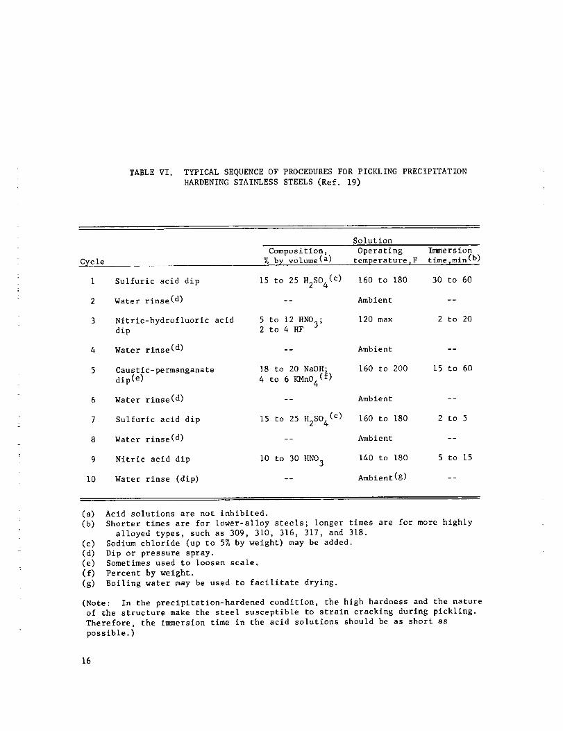
TABLEVl. TYPICALSEQUENCEOFPROCEDURESFORPICKLINGPRECIPITATIONHARDENINGSTAINLESSSTEELS(Ref. 19)
C_cle
i
2
3
6
7
8
9
I0
SolutionComposition,%by volume(a)
Operating Ima_ersiontemperature_F time_min(b)
Sulfuric acid dip 15 to 25 H2SO4(C) 160to 180 30 to 60
Waterrinse( d) -- Ambient --
Nitric-hydrofluoric acid 5 to 12HNO3; 120max 2 to 20dip 2 to 4 HF
Water rinse(d) -- Ambient --
Caustic-permanganate 18 to 20NaOH; 160to 200 15 to 60dip( e) 4 to 6 KMnO4(f)
Waterrinse( d) -- Ambient --
Sulfuric acid dip 15 to 25 H2SO4(C) 160to 180 2 to 5
Waterrinse( d) -- Ambient --
Nitric acid dip i0 to 30HNO3 140to 180 5 to 15
Waterrinse (dip) -- Ambient(g) --
(a) Acid solutions are not inhibited.(b) Shorter times are for lower-alloy steels; longer times are for morehighly
alloyed types, suchas 309, 310, 316, 317, and 318.(c) Sodiumchloride (up to 5%by weight) maybe added.(d) Dip or pressure spray.(e) Sometimesused to loosen scale.(f) Percentby weight.(g) Boiling water maybe usedto facilitate drying.
(Note: In the precipitation-hardened condition, the high hardnessand the natureof the structure makethe steel susceptible to strain cracking during pickling.Therefore, the in_nersiontime in the acid solutions shouldbe as short aspossible.)
16

TABLEVII. COMPOSITIONSOFELECTROLYTIC PICKLING SOLUTIONS
FOR VARIOUS STEELS (Ref. 19)
Material bein_ pickled
Low-carbon sheets
Low-carbon continuous strip
Plain carbon steel couplings
Ferritic and martensitic
stainless
Electrolyticunit
Acid in solutlon_% by volume
HCI H2SO 4 HNO 3 H3PO 4
A-c bipolar 2 to 3 ......
A-c bipolar 2 to 3 ......
D-c direct contact -- 5 to 15 ....
D-c direct contact -- I ....
A-c anodic -- 3 to 5 1 --
.... 1 3 to 5
17

TABLEVIII. PREFERREDBASE-METALCONDITIONFORJOINING(Refs. 9,10,11,12,14)
Alloy Arc Welding(a) ResistanceWelding Brazing
Stainless W17-4 PH
15-5 PH
Martensltic TyRes
Annealed Aged
Annealed for light Aged
sections, overaged
for heavy sections
Annealed for light Aged
sections, overaged
for heavy sections
414 Ti As received Aged
ALMAR 362 Annealed Annealed or aged
AI/_AR 363 As received As received
17-7 PH
PH 15-7 Mo
AM-350
AM-355
A-286
17-10P
HNM
Semiaustenitic Types
Annealed
Annealed
Annealed or aged
Annealed or aged
Transformed or aged
Transformed or aged
Annealed or aged
Annealed or aged
Austenitic Types
Not recommended (b) Annealed or aged
Not recommended Aged
Not recommended --
mm
_m
wl
Annealed or aged
Any
--m
(a) Conditions given are those which should be used to get maximum strengths when
welding these alloys to themselves.
(b) May be welded with specially designed filler metals; Inco 92 or Hastelloy W.
18

Plasma-Arc Cutting. For cutting metals, the plasma arc is established
between the electrode and the workpiece; various gases are used to form the
plasma, depending on the particular metal being cut. In contrast to the oxy-
acetylene process, where the cutting speed is limited by the rate at which the
chemical reaction between oxygen and iron proceeds, the cutting speed of the
plasma arc is limited only by the power available for cutting and the quality of
the cut itself. The quality of cutting is governed largely by the choice and/or
magnitude of the following process variables: (I) type of plasma gas, (2) gas
flow rate, (3) cutting speed, and (4) stand-off distances. Torch parameters such
as the size of the cutting tip and the selected power level are more in the nature
of dependent variables. Once they are selected, the process variables can be
adjusted to produce acceptable cutting. Care must be exercised in making such
adjustments when optimum cutting conditions are required, since minor variations
affect the smoothness of the cut surface, the amount of dross adhering to the cut,
and the production of an undesirable bevelled surface.
Applications. There is no indication in the literature that plasma-
arc equipment has been used to cut the precipitation-hardening stainless steels.
However, one of the equipment producers reported that two cormmercial steel supply
firms had cut such materials. (Ref. 20). Contact with one of these organizations
revealed that considerable quantities of 17-4 PH steel have been cut on a produc-
tion basis for general industrial use. (Ref. 21). Contoured shapes and blanks
have been cut without difficulty and, apparently, joint preparations for subsequent
welding operations were cut as well. Some evidence of edge cracking was noted
when a square blank was cut too close to the edges of a plate. Thicknesses up to
one-inch were cut. The second firm also reported cutting 17-4 PH steel with
plasma-arc equipment. (Ref. 22). Bar stock, about 2 inches thick by 3 inches
wide was cut for use in fabricating helicopter bell cranks. Although no difficulty
was experienced in cutting this stock, cracks were evident in the finished part.
19

However,it is not knownwhenthe cracks were first evident, since the bar stock
wasground, drilled, andmachinedto form the bell crank. Theparts werealso
heat treated after fabrication. Whenmaterials are cut with the plasmaarc, a
heat-affected zoneexhibiting microstructural changesfrom that of the original
basemetal occurs; dependingon the heat input, the zonemaybe as wide as 0.010
inch.
Experiencein plasma-arccutting of precipitation-hardening stainless steels
indicated that the cutting conditions are similar to those established for cutting
Type304 stainless steel. Theseconditions are as follows:
TABLEIX. PLASMA-ARCCUTTING CONDITIONS FOR
TYPE 304 STAINLESS STEEL (Ref. 21)
Tip Plasma Gas Flow Rate, Cutting
Thickness, Diameter, cfh Power, Speed,
in. in. N 2 H 2 A kw ipm
1/4 3/32 90 5 -- 30 35
1/2 3/32 90 5 -- 30 25
i 7/64 120 I0 -- 50 30
I 9/64 150 20 -- i00 55
I 1/8 -- 20 145 30 25
1-1/2 9/64 150 20 -- I00 30
1-1/2 1/8 -- 20 145 50 20
2 9/64 150 20 -- I00 15
2 7/32 -- 60 II0 i00 30
3 3/16 200 20 -- 150 I0
3 7/32 -- 60 Ii0 I00 25
4 3/16 200 20 -- 200 6
4 7/32 -- 60 II0 I00 25
5 7/32 -- 70 130 150 I0
6 7/32 -- 70 130 150 6
8 7/32 -- 70 130 150 4
Note:
20
For a given plate thickness there is more than one set of
conditions that will produce acceptable cuts.

DISTORTIONCONTROLANDTOOLING
Becauseof the pattern of heating andcooling whichdevelopsduring welding,
anyweldedpart is subject to a certain amountof distortion. Theamountof
distortion occurring in weldedpreclpitation-hardenlng stainless steels maybe
greater than that encounteredwith other materials, particularly low-alloy steels.
This is becausethe precipitation-hardening stainless steels expandmoreon heating
and do not conductthe heat of the arc awayfrom the weld area nearly as fast as
do low-alloy steel and other metals. Preclpitation-hardening stainless steels
also are subject to growthand contraction during heat treatment. For these
reasons, greater care is required to control distortion in precipitation-
hardeningstainless steel than is required for other metals.
Ling-Temco-Voughtmeasuredthe shrinkage acrossGTAweld joints in various
thicknesses of PH15-7Mosheet (Ref. 23). Thesheet thicknessesand the welding
conditions usedwere:
SheetThickness, Voltage,
inch volts
0.040 120.060 120.085 120.125 12
Travel Filler Wire Wire-FeedCurrent, Speed, Size, Speed, Heat Input,
amp ipm inch ipm _oules per inch
i00 15 0.030 25 4,800
160 14 0.030 29 8,230
190 I0 0.030 35 13,680
190 6 0.030 40 22,800
The amount of shrinkage that occurred in these welds is shown in Figure I.
A formula was developed for calculating the shrinkage as a function of the sheet
thickness. This formula is:
Weld shrinkage (inch) = 0.183 x sheet thickness (inch) + 0.00045
21

t-UC
0
t"
0'3
_P(,#1t.,.q.1
U'IC
I-
0.025
0.020
0.015
0.010
0.005
0"0000_20
//
Colcu loted/
oo )
0.040 0.060 0.080 O.I00 0.1200.085 -0.125
Sheet Thickness, inch
0.140
FIGURE I. SHRINKAGE OF GTA WELDS IN PH 15-7 Mo SHEET (Ref. 23)
22

The calculated values also are plotted in Figure i. These shrinkage values would
be affected by changes in any of the welding parameters and in the type of jigging.
For these welds, the pieces were held in a 3-foot-long stake welder fixture.
Spacing between hold-down clamps on opposite sides of the joint was 0.215 inch.
A copper backing strip with a groove width of 0.140 inch also was used. Ling-
Temco-Vought cautions that these values should not be extended to other materials,
thicknesses beyond this range, or the use of other welding parameters.
The type of welding process used also will influence the amount of weld
shrinkage. This is because different heat inputs and different amounts of metal
melted are associated with different welding processes. The most striking example
is that of electron-beam welding where the weld joint is much narrower than the
joints produced by arc-welding processes. In Figure 2, the shrinkage across the
weld joint for both electron-beam and GTA welds in PH 15-7 Mo is plotted (Ref. 24).
The shrinkage of electron-beam welds tends to be independent of material thick-
ness. This is because the width of electron-beam welds is relatively constant
for material in this thickness range.
A butt weld in precipitation-hardening stainless steel sheet will become
bowed in the direction of the weld. This is due to the lengthwise shrinkage of
the weld metal and is called the "drawstring effect". The weld also shrinks
across its width and, in so doing, will cause the two pieces being welded to draw
together and close up the joint ahead of the weld. Surprisingly, plates and sheets
may spread apart if the welding travel speed is high enough. Welds in plate do
not bow appreciably because the restraint is so high. However, they are subject
to angular distortion. This type of distortion occurs in plate because a beveled
joint and a number of passes are used. The opening at the top of the joint is con-
siderably wider than at the bottom of the joint. Moreover, the root pass acts as
a pivot, keeping the parts from pulling in uniformly across the joint width. Then,
as each pass after the root pass is put in and shrinks, it will pull the two
23

0O4
0
0
I-
\
rnLLJ
if}
50
q_u!
0
d
'g61)_lU!JqS
oo
0
0
(5
0
0
0d
0
0(5
00
o o0 oo0
U
,Z
C
U
i--
1--
00
v
,4
i-i
2_

pieces together at an angle. Fillet, lap, and corner welds also are subject to
similar distortions.
Growth or contraction occurring during heat treatment of these alloys is a
very important factor, especially in laying out parts to be fabricated in the
annealed condition and subsequently heat treated. The typical dimensional changes
occurring during heat treatment of these alloys are as follows (Ref. 25):
Alloy
17-7 PH
AM 350
Treatment
Transformation treatment (1400 F)
Aging treatment (950 or 1050 F)
Condition A heated at 1750 F for
I0 minutes, air cooled, plus-I00 F for 8 hours
Heating Condition R I00 for1 hour at 950 F
Subzero cool and temper
Double age
17-4 PH Aging at 900 F
Dimensional Change
Type Amount, in./in.
Growth 0.004
Contraction 0.0004 to 0.0007
Growth 0.0045 to 0.0051
Contraction 0.00028 to 0.00032
Growth 0.0045
Growth 0.004
Contraction 0.0004 to 0.0006
There are three basic methods of controlling distortion caused by welding:
(i) reduce shrinkage forces by controlling weld-bead sequence and heat input,
(2) offset the parts, and (3) restrain the joint by tacking and by using jigs and
fixtures.
DISTORTION CONTROL BY REDUCTION OF SHRINKAGE FORCES
Shrinkage forces cannot be eliminated. However, there are methods for re-
ducing the distortion caused by shrinkage forces. These methods include avoiding
overwelding, being sure of good flt-up, using backstep and skip welding, and
controlling heat input and preheat.
25

Excessweld metal mayincrease distortion becausethere is moremetal to
shrink. Ideally, the surface of a butt weld shouldbe flush with the surface of
the basemetal. This is difficult to do, so butt welds are madewith a small
amountof reinforcement. However,the amountof reinforcementshouldbe kept as
small as possible. For a fillet or lap weld, the strength of the joint is deter-
minedby the throat depth of the weld. Excessweld metal doesnot increase the
strength here, for oncethe fillet is large enoughthe basemetal becomesthe
weakestlink in the chain. Thesize of lap and fillet welds shouldnot exceed
the size indicated in specifications or on drawings. Thesurface of these welds
shouldbe as flat as the welder can makethem.
Onewayto avoid excessweld metal and, thus, reducedistortion is to use
correct joint spacing (gap or root opening). Usea joint openingwide enoughfor
goodpenetration, but no wider. If the openingis too wide, moreweldmetal will
be neededto fill the gap andmoreshrinkagewill occur. Correct joint gapusually
is no morethan 1/16 inch regardless of the welding processor thickness. Nogap
is possible with manyprocessesand thin materials.
Backstepand skip welding canbe used for long continuouswelds. In both of
thesemethods,short intermittent welds are made. For backstepwelding, eachbead
is started somedistance aheadof the previous beadand is weldedback to join the
beginning of the previous bead. A skip weld is a series of short beadsmadesome
distance apart. Thegapsbetweenthe beadsare weldedin after the beadshave
cooled. Thesetechniquesusually are usedwith shielded metal-arc welding or with
manualGMAwelding.
Whenwelding thin material, lengthwise or "drawstring" bowingof the part is
usually the most serious type of distortion. This canbe reducedby using as small
an electrode size (shielded metal-arc and_ welding) andas low a current setting
as is practical. In thicker material, crosswiseor angular distortion is moreapt
to occur. This canbe reducedby cutting downthe numberof passes,makingthe
passesheavier andincreasing the welding travel speed.
26

DISTORTIONCONTROLBYOFFSETTINGPARTSANDBALANCINGSHRINKAGEFORCES
If the operator can estimate the amountof shrinkage or distortion that will
occur in a particular weld joint, he can correct for this distortion by offsetting
the parts. Thewelding distortion thenwill pull the parts into the correct
position or alignment.
This methodis particularly goodfor T-joints. The"leg" of the T is off-
set before the weld is made. Theshrinkageof the weld pulls the leg to its
proper 90-degreeposition. If two weldsare to be made,one on eachside of the
leg, the "cap" of the T could be bent slightly before the welding with the same
results after the weldgare complete. Butt welds andcorner weldsmadefrom one
side canbe offset before welding to compensatefor distortion. Theamountof
offset required will vary greatly, dependingon the material thickness, welding
parameters,welding process, andwelding technique. Nospecific data are available
for the amountof offset required for precipitation-hardening stainless steels.
Offsetting or prebendingusually is used for short welds and simple shapes.
For long welds, or for welds in complexstructures, these methodsmaybecometoo
complicatedto give satisfactory results.
Shrinkageforces can often be balancedagainst eachother to prevent distor-
tion. DoubleV- or U-joints canbe weldedwithout angular distortion if the proper
welding sequenceis used. If the beadsare deposited alternately on opposite
sides of the joint, the shrinkageof one beadwill be balancedagainst the shrink-
age from the beadmadeon the other side of the joint andthe parts should remain
flat. Thesameresults canbe obtained in T-weldsby makingshort intermittent
welds on opposite sides of the leg.
DISTORTIONCONTROLBYTACKWELDINGANDJIGGING
Usually the most practical wayto prevent distortion is to fasten or clamp
the parts rigidly before welding so that they cannotmove. For simple welds,
this canbe doneby tacking before welding. For large parts for complexshapes
or for critical assemblies, jigs or fixtures are needed.27

Tack Welding. Tack welds are used chiefly to keep the parts from drawing
together or spreading apart during welding. In other words, they are used to
maintain the right joint alignment and gap. They will not prevent angular or
lengthwise distortion or bowing. Tack welds should always be used when the parts
are not clamped in a jig and sometimes they are useful even with a jig. The
spacing between tack welds depends on the thickness of the material--the thinner
the material the closer the tack welds. They may be as close as 3/4 inch, if
necessary.
Tack welds, however, can be a source of defects when the subsequent welds
are made. Tack welds are subject to cracking if they are too small. For this
reason, they should always be inspected and, if cracked, ground out before subse-
quent welding. Sound tack welds should be ground to a smooth contour that blends
evenly into the base metal. This will facilitate complete melting of the tack
weld into the subsequent weld.
JiRRinE. Jigs are used for two purposes: (i) to hold the pieces during
welding, and (2) to prevent distortion. For holding pieces together for welding,
jigs can be used with any thickness of material. To control distortion, though,
jigging is not very effective for material over about 1/4 inch thick. The shrinkage
forces that develop in welds of thick material become so great that a jig to hold
these forces would be too bulky to be practical. Thus, other means of controlling
distortion should be used when welding thick stain_ss steel sections.
Jigs can be simple or complex, depending on the shape of the parts being
welded. The complex jigs usually are intended for only one specific job run.
Simple Jigs, though, can be used for a wide variety of welding jobs.
The simplest jig consists of a backup bar, two hold-down bars, and some
C-clamps (Figure 3). The backup bar should be grooved so that proper weld pene-
tration can be obtained. This groove should be about 3/32-inch deep and about I0
times wider than the sheet thickness but never less than 3/16-inch wide. Copper
28

lnfloted fire hose
• _. /" _,/----Fixed bors
I/, c_J ucS ,_rI=. _ ./ _ ,_,1
"__"," Movoble hold-down bors
//"--IF--\\\
// L_ ___ --COpper hookup strip
L( "-- beocku p _.._ _ Port' being welded
FIGURE 4. SCHEMATIC SKETCH OF "FIRE-HOSE" JIGGING
29

is the best material for the backup bar. The weld metal will not fuse to the
copper and the copper will act as a chill bar to cool the weld joint quickly to
aid in reduction of distortion. The hold-down bars may be of steel or copper with
copper preferred if rapid cooling is desired. Water-cooled jigs are sometimes used
to confine the welding heat and promote fast cooling. The edges of the hold-down
bars are beveled so that there is room to weld.
Both the hold-do_n and backup bars should be rigid so that the weld shrinkage
will not bend the jig parts. The bars should be at least 1/2 inch thick. A good
practice is to make the backup bar of steel with a grooved copper insert. Added
rigidity can be obtained by using angles, T-sections, or T-beams for the hold-
down and backup bars.
Where long welds are to be made, these simple jigging systems often become
awkward to use. If the pieces being welded are also wide, it may be possible to
apply clamps only at the ends of the joint. To clamp the center of the joint would
require C-clamps with impractical throat depths. For such applications, special
jigs have to be built or purchased commercially. One jigging method uses common
fire hose as the clamping device. The fire hose is inflated with air under pres-
sure to force the clamping fingers against the parts being welded (Figure 4).
Other jigs use various types of mechanical fingers to apply the clamping pressure
and are called stake welders or stake fixtures (Figure 5).
Fillet welds and corner welds can be jigged using the simple "angle-iron and
C-clamp" equipment. The sharp corners on the angle p_ces should be ground off
so that good fitup can be obtained. As with butt welds long fillet or corner
joints will require special jigs. The examples given for butt welds can be modi-
fied easily for fillet and corner welds. The same jigging principles also apply
to edge and lap welds.
The tooling used in resistance welding precipitation-hardening stainless
steels is generally similar to tooling used in resistance welding other materials.
Resistance-welding tooling consists of suitable fixtures or jigs to hold the parts
30

31

in proper position for welding and to conduct welding current to the parts.
Sometimes tooling is also designed to index the part through the welding equipment
to insure that welds are made at the proper positions. The same general rules
followed in designing any resistance-welding tooling should be followed for tooling
designed for use with precipitation-hardening stainless steels. Generally, this
means that nonmetallic or nonmagnetic components should be used exclusively, and
the tooling should not contaminate the base metal.
JOINING PROCESSES
The precipitation-hardening stainless steels can be divided into two groups
on the basis of their weldability by fusion-welding processes. The martensitic
and semiaustenitic steels make up the first group. These steels are normally
weldable with filler metals which have compositions which are the same or simi-
lar to those of the base metal. In general, weldments in these types can be heat
treated to high strength after welding.
The second group is made up of the austenitic steels. Except in thin gages,
these are not weldable with filler metals of the same or similar composition.
When fusion-welded, low-strength stainless steel filler metals are usually used.
These filler metals avoid the weld cracking problems that occur when fillers of
the same composition as the base plate are used. Even when specialiy formulated
fillers are used, heat-affected zone cracking may still be a problem. Welds made
with normal stainless steel fillers cannot be heat treated to increase strength.
Consequently, either the strength of the joint must not be important in service or
the joint has to be thickened to reduce the service stresses in the weld.
Widespread use has been made of the arc-fusion and resistance-welding processes
for fabricating the precipitation-hardening stainless steels. Other processes
have also been used. Wide use has been made of brazing and some use of solid-state
32

welding hasbeenreported. Table X showsthe joining processeswhich havebeen
used for fabricating the precipitation-hardening stainless steels. Theseprocesses
are describedbriefly in AppendixA. Detailed descriptions of the processesand
the equipmentusedcanbe found in References19 and 26. Oxyacetyleneand other
oxy-fuel gas processesare not discussedhere (except for upset-butt welding)
since they are not generally used for fabricating aerospacecomponentsand
structures.
FUSIONWELDING
Fusion-weldingprocessesare those in which substantial amountsof molten
metal are producedduring the joining operation. Fusion-weldingprocessesfre-
quently are thought of being only the arc-welding processes. However,there are
other processesthat rightfully belong in this category, particularly resistance
welding. All of the fusion-welding processesthat commonlyhavebeenused in the
fabrication of precipitation-hardening stainless steel hardwareare included in
this section.
Thearc-welding processeshavehad wide application in joining precipitation-
hardeningstainless steels. Themost frequently usedhas beenthe gas tungsten-arc
process (GTA). Shieldedmetal-arc and gasmetal-arc (GMA)processeshavebeenused
to a lesser degreewhile the use of submerged-arcwelding is quite limited.
Electron-beamwelding is finding ever wideningacceptance,particularly in the
joining of thin sheet. Plasmawelding is only in the experimentalstage, although
the application of plasmafor cutting is relatively cormnon.
Resistancespot welding has beenusedextensively for fabricating a limited
numberof the precipitation-hardening stainless steels. Seamwelding, projection
welding, and flash weldingalso havebeenusedfor thesealloys but to a lesser
degree. Theuse of high-frequency resistance welding and stud welding has been
limited.
33

v
[--4o'3
IzoE_
H
L)
p_O
ZO
L)
E)
or)OO
_.)
u}
QJOO
34
0_
.r-iN
0_
•r-I 4J o,--i
O 4J _
_ o_
•,_ ._ _ ,,-nm 0 0
0
(11 I:_
E
_ 4..1 _
_J_.J
E_
"O_J
u
E.<
¢J
•_-I 4J 4J 4J
(_ _ O _ s N
_1 _J ._J ,_
O ,--_ _
rj 03
I ¢J! .M _1 I_
_ O
,._ _J _0 _ _ 0_)
_ O I_ • O"El _ ._ ::_ _J .,_ _J
_ _ I 0J <11 _ _J _ I_ _ 0 _ r-.-. 0_ N 0 _ _E:
_ _J _ _ ,_ _ ._ :_ o0
r3_ 03 _/} o_
v
Z
{J
4J
4J
z Z z z
v
o
X X
o
! I

o
.IJ
00v
•_I .I-Iv-I _10 .i-I
18RI
I_ • .,-Itl/ O_ ,IJ
•,-I 4J _1 .r-q0 0
O'0
0
u _
Em u
i11
i1_ i-i
04J
oo
_ r_
X
o'3v
!
! !
v v
Z
0
v v v35

Shielded Metal-Arc Welding. The shielded metal-arc process (also called
metal-arc, stick, or covered-electrode welding) can be used for welding the
precipitation-hardening stainless steels that do not contain aluminum (17-4 PH,
AM 355, and AM 350). (This process cannot be used for welding the aluminum-
containing steels due to the difficulty in recovering aluminum in the base metal.)
Shielded metal-arc welding is a very versatile process that can be used for produc-
ing high-quality welds in all positions (flat, horizontal, or vertical). With
care, steel as thin as 1/16 inch can be welded by this process.
Electrodes are available commercially for welding 17-4 PH, AM 350, and AM 355.
These electrodes have a titania covering that enables the electrodes to be used on
either a-c or d-c. Normally, an electrode with the same composition as the base
metal is used. If the welds will not be heat treated to achieve high strengths,
standard austenitic stainless steel electrodes can be used, e.g., E308 or E316
(Ref. 27). 17-4 PH electrodes may be used to weld 17-7 precipitation-hardening
steel (Ref. 7). Reasonable heat-treatment response can be obtained if high weld-
metal dilution is obtained. This means the operator should "dig in" the electrode
when welding to melt as much base metal as possible.
The covering on these electrodes has a tendency to pick up moisture from the
air if the electrodes are not kept in a closed container. Moisture in the elec-
trode coating may cause porosity in the weld metal. Thus, electrodes from freshly
opened containers should always be used if possible. If electrodes must be used
that have been out of the container for some time, they should be dried in an
electrode drying oven. Usually, it is well to keep electrodes in a drying oven
after the container has been opened. The temperature of the drying oven should
follow the electrode manufacturer's recommendations.
Types of Weld Joints. Typical weld joints for use with the shielded
metal-arc process in precipitation-hardening stainless steel are shown in
Figures 6 and 7. The root gap and root face dimensions shown in these figures
36

or
I--,,,6-
o. 1/8 to 3/16-inch-thick bose metol
FIGURE 6.
b. 3/16 to I/P-inch thick bose metol
JOINT DESIGNS FOR SHIELDED-METAL-ARC WELDS IN PRECIPITATION-HARDENING
STAINLESS STEEL, BASE METAL UNDER 1/2 INCH THICK
LIlt6 to 3/16" _ 1"4---118 to 1/4
._ -'--- 15"
3.,.,,
FIGURE 7. JOINT DESIGNS FOR SHIELDED-METAL-ARCWELDS IN
PRECIPITATION-HARDENING STAINLESS STEEL,BASE METAL OVER 1/2 INCH THICK
37

are approximateandmayvary according to the thickness of plate being joined,
the welding position, and the diameter of the electrode.
For welding plate wherethickness is 3/16 to 1/2 inch, the edgesof the plate
are beveledto producea 60-degreeV-joint (Figure 6). Weldsin material 1/4
inch or morethick shouldbe madewith a minimumof two passes.
For welding plate which thickness exceeds1/2 inch, a single- or doubleU-
grooveor a doubleV-grooveshouldbe used (Figure 7). A J-groove should beused
for fillet and corner welds. Although the U- andJ-grooves are moreexpensive
to prepare, less filler metal is required to fill them. Cleaningbetweenweld
passesis required andthe backsideof the root passshouldbe groundto solid
metal before welding from the backsideof a doubleU- or doubleV-joint.
WeldingProcedures. Nounusualproceduresare required for shielded
metal-arc welding of precipitation-hardening stainless steels. Welderstrained
in the welding of conventional stainless steels have little difficulty in learning
to makegoodwelds in precipitation-hardening stainless steels. Recommended
welding conditions are available from the electrode supplier, although these
recommendationsshould serveas a guideonly. Thebest conditions for any appli-
cation will vary, dependingon joint shapeandalignment, metal thickness,
proximity of chill bars, and the operator's preference. Typical conditions are
given in TableXI.
Precautions. Theheat-treatment responseof welds in precipitation-
hardeningstainless steels will vary with the compositionof the weld metal. The
compositionof AM350andAM355welds shouldmatchthe compositionof the base
metal as closely as possible so that the weld-metal strength will be similar to
the base-metalstrength (Ref. 7). However,the weld-metal compositioncanbe
affected by the travel speed,arc length, and the operator's technique. For this
reason, qualification of the welding operator is very important to ensurethat
38

TABLE XI. SUGGESTED WELDING CONDITIONS FOR
SHIELDED-METAL-ARC WELDING OF
PRECIPITATION-HARDENING STEELS
Electrode
Diamter,
inch
Arc
Voltage,
volts Flat
Current, _mpVertical and
Overhead
1/16
5/64
3/32
1/8
5/32
3/16
20-22
20-23
22-25
23-25
23-26
24-27
25-40
35-55
40-70
70-120
100-145
125-190
20-35
30-55
35-65
55-85
80-120
100-155
39

the operator is using procedures that will produce weld joints with the desired
properties. In general, shielded metal-arc welding of precipitation-hardening
stainless steels should be done with a short arc length. Long arcs cause a loss
of chromium from the weld metal.
In multipass welding, each bead should be cleaned and wire brushed before
the next bead is deposited to ensure that slag is not trapped in the weld. If
welding is done from both sides, the underside of the root pass should be ground
or chipped out to clean, solid weld metal before the back weld is made to eliminate
slag entrappment and ensure full penetration.
It is important to always fill the crater before breaking the arc. A thin
crater will be weak and may crack on cooling. Crater cracks are very difficult
to remove when the subsequent pass is deposited. If they do occur, the crater
should always be ground out before the next pass is deposited.
After the weld is completed, all welding slag should be removed from the
surface of the weld joint. Particles of welding slag left on the surface can
cause corrosive attack during subsequent service, particularly, if high-temperature
service is anticipated.
Gas Tungsten-Arc Welding. The manual and automatic GTA welding processes
are the most frequently used processes for joining precipitation-hardening stainless
steels. High-quality weld joints can be produced in all types of precipitation-
hardening stainless steels with thicknesses up to about 1/4 inch. GTA welding
can also be used for welding material thicker than 1/4 inch, but welds can be made
more economically and faster if the GMA process is used for these thicknesses.
With GTA welding, the welding heat, the amount of penetration, and the bead shape
can be very accurately controlled. Interpass or elaborate postweld cleaning
operations are not required as there is very little spatter, there is no slag
crust, and the bead surface is smooth and uniform. GTA welding operations can
be manual, mechanized, or fully automatic.
40
Most precipitation-hardening stainless steel is GTAweldedusing direct
current at straight polarity. Conventionald-c powersupplies (the motor genera-
tor or rectifier) having a droopingvolt amperecharacteristic are used for GTA
welding. Thesepowersupplies usually are equippedwith high-frequencyarc
starting devices for initiating the welding arc. Alternating current powersup-
plies sometimesare usedfor welding the precipitation-hardening stainless steels
that contain aluminum. This is becausethe alternating welding current tends to
eliminate the aluminumoxide scumwhich sometimesformson the surface of the
moltenweld metal. Alternating current powersupplies shouldbe equippedwith
devices for superimposinga high-frequencycurrent.
Electrodes for GTAwelding precipitation-hardening stainless steels are
madefrom either pure tungsten or tungsten alloy with 1%thorium with the thoriated
tungsten electrodes being preferred. Comparedto pure tungsten, the thoriated
electrode lasts longer, makesarc starting easier, has a morestable arc especially
at low currents, and has less tendencyto spit off particles of tungsten into the
weldmetal. The size of the electrode to use is governedby the amountof weld-
ing current that is required to makethe weld. Theelectrode sizes to be used for
various current settings are given in Table XII. If the wrongsize of electrode
is used, the arc maybehard to control or tungsten maybe deposited in the weld
metal.
For welding precipitation-hardening stainless steel, the electrode is ground
to a sharp point or to a point wherethere is a slightly roundedtip. During
welding a small ball of molten tungstenwill form at the end of the electrode.
As long as this ball is small it will not interfere with goodarc control. How-
ever, if the current is set too high for the size of the electrode being used,
the molten ball will becomelarger and the arc will be harder to control. A
dangeralso exists that a large molten ball on the end of the electrode maybecome
41

TABLEXII. RECOMMENDEDCURRENTRANGESFORTUNGSTENANDTHORIATEDTUNGSTENELECTRODES(Ref. 26)
ElectrodeDiameter,
inch
Direct CurrentStraight Polarity,
Both PureTungstenand
Thoriated Tungsten
Current RangeL amperes(a)Alternating Current, Alternating Current,
UnbalancedWave BalancedWavePowerSupply PewerSupply
Pure Thoriated Pure ThoriatedTungsten Tungsten Tungsten Tungsten
O.O4O 15-80 10-60 15-80 20-30 20-60
1/16 70-150 50-100 70-150 30-80 60-120
3/32 150-250 100-160 140-235 60-130 100-180
1/8 25O-4O0 150-210 225-325 100-180 160-250
(a) Thesecurrent values are for argon shielding gas.
42

dislodged anddrop into the moltenweld puddle. Theobvioussolution to avoid
such tungsten contamination is to use the next larger size tungsten electrode.
Caremustbe exercised to avoid contaminationof the end of the electrode.
Electrode contaminationusually is causedby touching the end of the electrode to
the molten weld metal. Whenthe electrode is contaminated,a large molten ball
of a mixture of tungsten and the basemetal will form on the tip of the electrode.
If this happens,the welding operation should behalted and the electrode reground
to removethe contaminatedportion.
Filler-wire feeders are usedin mechanizedand automaticGTAwelding to add
filler wire to the weld at a closely controlled speedand location. Thewire is
fed from a spool by motor-driven feed rolls whosespeedcanbe regulated accurately
over a wide range. An adjustable metal guide tube directs the wire into the weld
puddle at the correct angle anddirection. Theguide tube usually is attached to
the welding torch so that the correct alignmentbetweenthe electrode and the
filler wire canbe maintained. In manualwelding, a foot control usually is used
to regulate the welding current. Theoperator can start the weld at a low current
andthen build up the current to the desired level during welding by operating the
foot control. At the endof the weld, the current canbe loweredto eliminate a
crater whichmayotherwise form. Also, the current canbe reducedwhentying in
with a weld already made.
Argonor helium or a mixture of the two gasesare usedto protect the endof
the electrode, the arc, and the moltenweld puddle from the atmosphereduring
welding.
Argon is used for manualGTAwelding of precipiation-hardening stainless steel
for several reasons. In argon, the arc is smoothandeasy to start and control.
Comparedwith helium, the arc in argon is cooler whichmeansthat the weld puddle
will be smaller and the welding operator will havebetter control over penetration.
Argonis moreeconomicalto use than helium becauseit is cheaperandbecause
43

lower flow rates are usedwith argon. Since argonis heavier than air, while
helium is lighter than air, the argonblankets the weld area better than helium.
For helium to shield as well as argon, the flow rate must be two to three times
that of argon. Argonalso p_ovidesbetter shielding if there are anydrafts or
breezesthat might disturb the gas shield.
Heliumusually is used for automaticwelding because,first, the arc is
hotter, and second,the arc length can be controlled moreaccurately than with
argon. Thehigher heat of helium-shielded arc permits high travel speedsto be
used. Thetravel speedcan be increased as muchas 40%by using helium instead of
argon. AutomaticGTAwelding is frequently used in high production applications,
whenhigh travel speedsare important. Occasionally, helium maybe used for
manualGTAwelding very thick parts wherea great manypassesare required to
fill the weld joint. By using helium instead of argon, heavier passescanbe
madeand the joint canbe completedquicker. In automaticwelding, the arc length
is controlled throughmeasurementof changesin arc voltage. Thesechangescan
bemeasuredmoreeasily whenthe arc is shielded with helium. Thus, the arc
length canbe controlled moreaccurately in helium than in argon.
A mixture of argonand helium is sometimesusedin automatic GTAwelding.
Themixture is usually used to obtain an arc that is less penetrating than the
arc obtained with pure helium. A mixture of argonand heliummight be usedwhen
welding very thin stainless steel to prevent burnthrough. Thearc will become
cooler as the amountof argon is increased. Usually, mixtures are 25 argon-75helium,
or 50 argon-50helium. These,as well as other mixtures of argonandhelium, can
be obtained already mixed in tanks from gassuppliers. Special valves and control-
lers are also available that allow the user to mix the gasesin any ratio desired
from tanks of pure argonandhelium.
Filler wire is used in GTAwelding to fill up a joint that has a V- or U-
shapeor a joint that has poor fitup. Filler wire should be usedwhenmakingbutt
welds in 1/16 inch or thicker material so that the weldwill havea goodbead
44

reinforcement. Filler wire also should be usedwhenmakingfillet welds. Lap
and corner welds require filler wire whenthe basematerial is over about 1/8 inch
thick.
Thediameter of the filler wire that is usedwill dependuponthe thickness
of the material to beweldedandthe current settings. Filler wire that is too
large will take too much of the welding heat to melt it and the weld may lack
penetration. If the filler wire is too small, the welder may have difficulty
feeding it into the weld pool fast enough to build up the weld bead properly.
Proper guiding of the filler wire into the weld puddle also is important.
Weld-metal porosity has been caused by erratic guiding of the wire (Ref. 28).
This porosity was eliminated by always guiding the wire into the puddle on the
joint centerline and at the puddle leading edge.
Types of Weld Joints. Figure 8 shows recormmended butt joints for
GTA welding various thicknesses of precipiation-hardening stainless steels
Although these joint designs are recommended for PH 15-7 Mo sheet, they could be
used for the other precipitation stainless steels as well.
Welding Procedures. The GTA welding of precipiation-hardening stain-
less steels requires no unusual welding procedures. However, optimum quality welds
require close control of the welding operation and the exercise of certain precautions.
Conditions used for welding the precipitation-hardening stainless steels are
similar to those used to weld the austenitic stainless steels. Typical conditions
are given in Table XIII. When welding the precipitation-hardening stainless
steels that contain aluminum the scum that forms on top of the molten weld metal
may become a problem to the operator. In this case, the operator may prefer to
use alternating current instead of direct current straight polarity. This scum
normally does not create any major problems, however, it is a nuisance, detracts
from the appearance of the weld, and tends to hinder flow of the molten weld metal.
45

Material thickness
0.020 to 0.125"
Mjnimum thickness 0.010"
for automatic welding
0.002 to 0.020"
(Automatic welding only)
_ _oo6o,,.oo,o.,l _c__ /
0.060"--_ _-0.062" R
f 0.005"
/Lo.o6o"
0.080 to 0.250"
0.125 to 0.375"
_,,_-- 35°--_/
3/,6"_/ L-o.o6o"
0.375" to 0.750"
FIGURE 8. TYPICAL BUTT JOINTS FOR GTAWELDING
PRECIPITATION-HARDENING STAINLESS
STEEL
46

z_
! I--4
E--_o_
OZ0
r._ F-_
1--4 I-'4
o
H
x
OO
14-1
• ,-4 O
,--4 .r._ q-_
,-4 _
_D :
O l
0 E •
•"_ 0
• _ 0 I
0
gl
";j
>
_S
,--4 _ _1
0
4J
_ _ O'3 r_ t_ r_ _ t_ r-.. -,.1" ....1" ...1- _ -...1- u'__ _ co _ _ _-1 _-1 _ CM I:_ _ co _, 0(3 _
O
>
b8 " " '-,1" O0 u _, e% ¢xl 0 0 0 0 0 0 0
0
r-_ oq 0"%
•-i=1 q_ Q)
r-,- c_ r-,. 0 u_ _ -.5- oo _ 2:
_m
t'M I/3
I N
o _ o 00 _ _ _ _ c_ o o o o o _ ,_ .._ ,o _ _ _ _ ,- _ _ _ _ _ _ ,._
u-_ Lt_ Lt_ Lr_ Lt_ Lt_ L/_ I_• • • •
",Dr--I
on 0 0 0 0 0 0 0 0 0 _
0 0 0 0 0 _-_ _ 0 0 0 0
I O _
47

The film also tends go act as an insulating barrier to the weld metal which re-
duces the heat input into the weld, thus a somewhat higher welding current may be
necessary to obtain complete penetration when using direct current. Some arc
wander also may be induced by the scum.
Protection of the underside of the weld joint always is necessary to prevent
oxidation of the backside of the weld and to insure smooth contour of the weld
metal on the backside of the joint. The most common way of protecting the back-
side of the weld joint is to use a grooved copper bar. The pieces being selded
are held tightly against the bar with clamps. By drawing heat away from the weld
zone, the copper backup bar prevents burnthrough to the joint. If too much metal
should be melted, the backup bar will support the molten metal and prevent it from
dripping through the joint. If the backup bar is not used, the underside of the
weld bead would be open to the atmosphere and could pick up contaminants from the
air. For welding light gage precipitation-hardening stainless steel, better pro-
tection is obtained by reducing the size of the groove in the copper backup bar.
For general welding of these thicknesses of material the groove should be about
3/32 inch wide and about 0.015 inch deep. With the bar in place only a small
amount of air contained in the groove itself can contact the underside of the
joint. Thus, much less contamination can occur. However, if it is desired to
completely shield the underside from air, a gas-shielding backup bar can be used.
This bar has provisions for flowing argon or helium into the groove and thus only
an inert gas comes in contact with the underside of the bead. A typical backup bar
of this type is shown in Figure 9.
For critical applications, the dimensions of the groove are very important.
The chilling effect of the copper backup bar varies inversely with the width of
the groove, i.e., the narrower the groove, the greater the amount of chilling.
This, in turn, affects the width of the fusion and heat-affected zones of the
weld joint. Ling-Temco-Vought has specified the dimensions of the groove for
48

0
0
0
0
i
Copper_
insert __...._,. . ,.
Steel IX \ \ ,,///,..,]_/[.1"._/._
FIGURE 9. TYPICAL BACKUP BAR WITH GAS BACKING
49

various thicknesses of PH 15-7 Mo sheet so that uniform weld joint widths are
ensured (Ref. 28). These dimensions are given in Table XIV.
Cooling of the weld joint also is affected by the spacing of the hold-down
bars. Typical spacing as used by Ling-Temco-Vought for various thicknesses of
PH 15-7 Mo sheet also is given in Table XIV. The copper hold-down bars were con-
tinuous for material thinner than 0.060 inch. When segment bars were used on
thicker material, the spacing between segments was kept less than 0.010 inch. The
hold-down bars should have some flexibility so that good metal-to-metal contact
between the bar and the workpiece is ensured.
The dimensions of backup groove and the clamp spacing given in this table
were developed for a specific application (XB-70 skin panels) and are not necessarily
the best for all welding operations. The point that is being made is that for
critical use where uniform weld joint dimensions and quality are required, these
jigging parameters must be closely controlled so that uniform cooling is obtained.
As a corollary, close control of the welding parameters also is required, other-
wise precise jigging is meaningless.
For best results, the arc should be started on a tab of the same material as
the base metal. The u6e of the starting tab permits the establishment of a steady
arc before welding of the joint is begun. It also allows time to adjust welding
conditions and to observe any irregularities in arc behavior. The arc should be
initiated by high-frequency starting rather than by touching the electrode to the
starting tab. Touching the electrode to initiate the arc can cause contamination
of the electrode which in turn may result in an erratic arc. It is best to use a
runoff tab at the end of the weld so that the weld can be ended outside of the weld
joint. This avoids the formation of a crater within the weld joint. If it is
impossible to use a runoff tab and the weld must be ended within the joint, then
techniques should be used to fill in the crater before the arc is broken off. The
presence of a crater in the weld joint can lead to the formation of cracks in the
weld metal.
50

TABLEXIV. DIMENSIONSFORTOOLINGFORGTAWELDINGPHI5-7MoSHEET(Ref. 28)
Sheet Backup Backup Hold-downthickness, groovewidth, groovedepth, clampspacing,
inch inch inch inch
0.002-0.010 0.025+0.005
0.011-0.020 0.045+0.005
0.021-0.040 0.090+0.005
0.041-0.060 0.187+0.010
0.061-0.090 0.250+0.015
0.091-0.190 0.312+0.015
0.191-0.250 0.375+0.032
0.251-0.500 0.437+0.032
0 015+0.005
0 030+0.005
0 030+0.005
0 040+0.010
0 040+0.010
0 060+0.010
0 060+0.010
0.060+0.010
3/32_+i/32
3/16_+i/32
3/16_+i/32
I/4 ii/32
5/16_+1/16
i/2 il/16
5/8 _3/32
7/8 _3/32
51

Precautions. During the courseof makingthe weld, several diffi-
culties maybe encountered. Themorecommonof these include are wander, tungsten
pickup, disruption of the gas shielding, and lack of penetration.
Arc wanderis the namegiven whenthe arc movesfrom one side of the joint to
the other instead of playing on its centerline. Arc wanderin GTAwelding of
precipitation-hardening stainless steel canbe causedby a contaminatedelectrode,
a blunt electrode, a magneticfield, or air drafts. Arc wanderdue to a contamin-
ated or blunt electrode usually is a rapid movementof the arc from one side of
the joint to the other. If the arc movesbackand forth slowly or stays on one
side of the joint, magnetic fields or air drafts are probably the cause. Arc
movementcausedby a magnetic field usually canbe solved, or at least minimized,
by changingthe position of the groundcable attachment. Sometimessteel jaws of
hold-downclampsbecomemagnetizedandalso can disrupt the arc.
Bits of tungsten canbe picked up in the weld metal if the arc is struck on
the workpieceor if the welding current is too high. Starting the arc by touching
the electrode to the workpiececan causethe tip of the electrode to weld itself
to the work just as the two touch. As the electrode is withdrawnto start the
arc, a bit of electrode will break off and remain in the joint. This canbe pre-
vented by using the high-frequencystarting or by starting the arc on a starting
tab.
If the inert gas shield is not performingproperly, air will comein contact
with the moltenweld metal andhot baseplate and causecontamination. The gas
shield canbreak downfor several reasons: (1) the flow of shielding gas is too
low andthe weld metal is not completelyprotected, (2) the flow of shielding gas
is too high andturbulence is created which sucksair into the shielding gas,
(3) drafts canblow the shielding gasaway, (4) the gas-supplyhose fittings or
gaspassagesin the torch are blockedor loose.
52

A weld joint that show_lack of penetration is not getting enoughwelding
heat. This usually meansthat the current is too low or the travel speedis too
high. In GTAwelding this canalso meanthat the diameter of the filler wire is
too big or that the filler wire is being dipped into the weld puddle too frequently.
Toomuchof the weldingheat then is being taken to melt the filler wire. To get
proper penetration, the welding current, travel speed, filler wire size, and
filler wire feeding rate must be carefully balanced.
Applications. GTAwelding is the most frequently usedprocess for
welding the precipitation-hardening stainless steels. This is becausethis pro-
cess produceshigh-quality welds, close control of the processparametersis
provided, it is easy to use, and weldscanbe madeboth manuallyand automatically.
Sometypical applications follow.
GTAwelding wasused in onestep of the fabrication of honeycombpanels for
the wing surfaces of the XB-70(Refs. 32 and33). Thecover sheets for these
panels had stiffeners weldedto the panels at periodic intervals. Thesestiffeners
were attached by the GTAprocessusing a melt-through technique. Thepanelswere
madefrom PH15-7Mo. Coversheetsand stiffeners were 0.042 to 0.072 inch thick.
Thestiffeners wereabout i inch high.
In the melt-through technique, the weld is madeon the top side of the sheet
without a joint or gap (Figure I0). Sufficient melting takes place so that the
edgeof the vertical stiffener is fused into the joint. Optimumweld shapeswere
obtained using relatively high welding currents andwelding speedsslightly on
the low side. PH15-7Mofiller wire 0.030 inch diameterwasadded. Tooling
included inert-gas backup. Thegasbackupnot only protected the underside of the
weld joint from the air, but also acted as a support for the molten weld metal.
Jigging for these parts wasspecially designedalthough it followed conven-
tional concepts. Hold-downfingers, actuated by fire hose, clampedthe cover
sheet to the copperbackupbar (Figure ii). Fire hoseis not shownin the figure.
53
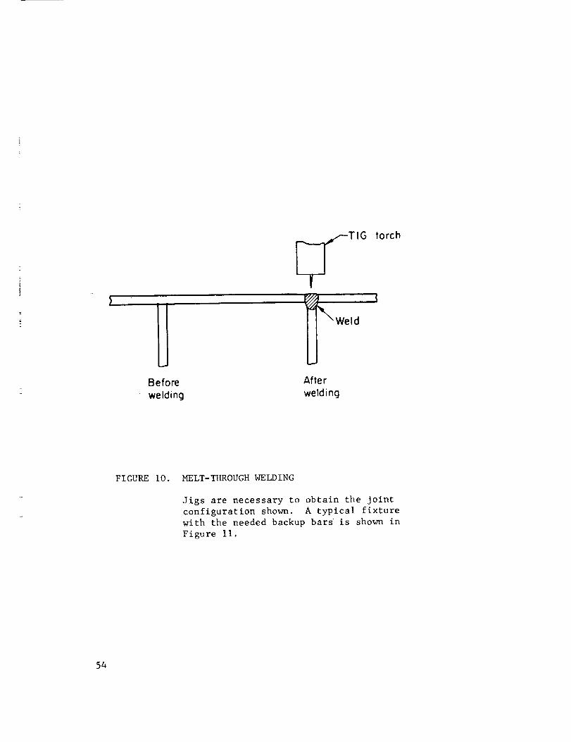
Before
welding
_TIG torch
_X, Weld
After
welding
FIGURE I0. MELT-THROUGHWELDING
Jigs are necessary to obtain the jointconfiguration shown. A typical fixture
with the needed backup bars is shown in
Figure II.
54

A
A. Copper-tipped hold-down fingersB. Ponel sheet
C.& H. Copper bockup bors. ('1:" is fixed, "H" is movoble to
clamp verticol stiffener)
D. Spocer to support verticel stiffener
E._ d. Inlets for inert beckup gosE Rubber sp(]cer
G. Structurol support
I. Arm to move copper bockup berK. Holder
FIGURE Ii. FIXTURE USED TO HOLD PARTS FOR
GTAMELT-THROUGHWELDING OF
STIFFENED PANELS OF PH 15-7 Mo
(Ref. 32)
55
The copper backup was split to hold the vertical stiffener. Gas passages were
machined into the copper backup to provide for the inert-gas backing. After the
parts were clamped in the fixture, the automatic GTA welder traversed the joint,
riding on a horizontal rail also mounted adjacent to the fixture (Figures 12 and 13).
Accurate tracking depended on precise location of the welding head rail and the
positioner.
Ling-Temco-Vought developed conditions for automatically welding PH 15-7 Mo
sheet and plate out-of-position (Ref. 74). This work was prompted by the fact
that the parts being welded (aircraft and missile frames) had increased in size
to the point where they could no longer be positioned for flat-position welding.
PH 15-7 Mo plate 0.56 inch thick was welded in the horizontal and overhead
positions. Conventional automatic-welding procedures were used. The weld joint
was a single vee. A joint included angle of 20 to 25 degrees was recommended.
All welding was done from one side. However, "straightening" passes were used on
the back side of the joint. After each welding pass, the joint was allowed to
cool to room temperature. Then, a simple melt pass with no filler wire was made
on the joint back side. The shrinkage of the melt pass counterbalanced the
shrinkage of the weld pass and, thus, overall distortion of the joint was appre-
ciably reduced.
PH 15-7 Mo sheet with thicknesses in the range of 0.031 to 0.125 inch were
welded in the horizontal, vertical-up, and overhead positions. In the horizontal
position, best results were obtained when the flow of shielding gas through the
gas backup bar was kept low (5 cfh). This allowed a slight oxide film to form on
the back surface of the weld bead. This oxide film increased the surface tension
and retarded sagging of the molten weld metal. For overhead welding, relatively
slow welding speeds permitted capillary action to draw the molten weld metal up-
ward in the weld joint. This produced a good contour on the back side of the weld.
56

F_0
ozE-4
r_r_
v_
H
0
r_
v_
C_
cf_
V
57

\
O
0 I
0
ct_
r_
v
58
A combination of close control of welding parameters and tight fitting chill bars
were required to produce good welds in the vertical-up position. Variations in
parameters beyond rather close limits produced sagging of the weld bead and weld-
metal porosity.
Lockheed Missile and Space Company has been using 0.040-inch-thick AM 350
sheet to fabricate toroidal tanks for thrust vector control of the Polaris A3
(Refs. 35_ 363 and 37). To produce tanks that had optimum properties to ensure
satisfactory performance, the effects of variations in welding procedures on the
fracture toughness of the weld joints were determined. The results of Lockheed's
work suggested that, where good fracture toughness of the weld joint is important,
AM 350 filler wire should be used in preference to AM 355 filler wire. Repair
welding should be done after the weldment is fully heat treated and the repair
welds should be left in the as-welded condition. Heat treating after repair weld-
ing results in very erratic fracture-toughness properties in the repair weld.
Gas Metal-Arc Welding. The gas metal-arc welding process has been used
for welding precipitation-hardening stainless steels thicker than about 1/4 inch.
(IMA welding produces high-quality welds at higher welding speeds than does GTA
welding. However, the higher heat input of GMA welding limits its use to the
relatively thick parts. Since most precipitation-hardening stainless steels are
used in the form of thin sheet material, the use of GMA welding is rather limited.
The use of GMA welding is limited to the flat or horizontal position.
The metal that is melted off the end of the electrode filler wire transfers
across the welding arc to the weld puddle as a spray of very fine metal droplets
(Figure 14a). These droplets are too fine to be seen individually. The droplets
are interspersed in the arc itself and the combined arc-metal spray has the shape
of an inverted cone. The end of the electrode takes on a pointed shape as it melts.
Two electrical requirements must be met if spray transfer is to be achieved:
(I) reverse-polarity direct-current must be used, and (2) the welding current must
59

./-Nozzle
Molten weld metol-_ ___// _Filler wiref,_._
! j J j-Arc plus sproyof fine
Solidified 'k // )/11_(,_ _ metol dropletsweld me,o,---_ 'k,>c.,/9'7.'_I_',_ ._'_. /--Shielding gos
o. Sproy Tronsfer
Spotter--_ .
k-_. \ \\.'k,_
Ar c column
orge drops of molten metol
\\\Yb. Globulor Tronsfer
FIGURE 14. GAS-SHIELDED METAL-ARC WELDING WITH SPRAY AND GLOBULAR TRANSFER
6O

be above a certain critical level. Globular rather than spray transfer will occur
if either of these requirements is neglected (Figure 14b). In globular transfer,
large balls of molten metal will build up on the end of the electrode and drop
into the weld puddle. When this occurs, the arc is hard to control, penetration
and bead shape are poor, and there is a lot of spatter. The critical level of
welding current depends on the size of electrode filler wire that is being used.
Higher currents must be used for larger wire to obtain spray transfer.
A variation of gas-shielded metal-arc welding is called short-circuiting GMA
welding. In this process the end of the electrode wire rapidly and repeatedly
touches the molten weld puddle. Each time this occurs, the molten end of the
electrode wire transfers to the molten weld puddle. Several years ago, short-
circuiting GMA welding was investigated briefly as a method for welding 16-gage
PH 15-7 Mo sheet (Ref. 38). Although results were satisfactory, this process has
not been used for production welding of precipitation-hardening stainless steels,
as far as is known.
Equipment. The equipment needed for gas metal-arc welding includes
a power supply, a welding gun, a mechanism for feeding the filler wire, a set of
controls, and a shielding gas.
Two types of power sources are used for spray-transfer GMA welding. These
are the constant-current drooping-voltage type and the constant-voltage type, with
the constant-voltage type finding the widest use. Motor generator or d-c rectifier
power sources of either type may be used.
Both manual (usually called semiautomatic) and automatic welding guns are
available. Both manual and automatic guns have a nozzle for directing the shielding
gas around the arc and over the weld puddle. The wire passes through a copper con-
tact tube, located in the nozzle, where it picks up the welding current.
Manual guns differ in design in the manner in which the electrode wire is fed.
Some manual welding guns contain the wire-driving mechanism in the gun proper.
61

Theseare called "pull" gunsbecausethey pull the wire into the gun. Thedrive
rolls maybe poweredby an electric motor contained in the gunor by a flexible
shaft leading from a motormountedin the control unit. Someof the gunsthat
contain the wire-drive motor also hold a small spool of filler wire. While these
gunsare bulkier than the other types, the numberof connectionsto the control
unit are minimized. Thewire-drive mechanismalso maybemountedon the control
unit with the wire being driven through a flexible conduit to the welding gun.
This is called a "push" type of wire drive. Thegunis less bulky than the pull
type. Small-diameterwire maybuckle whenfed long distances by a push-type
mechanism.Thus, the wire-drive mechanismmust be placed relatively close to the
welding station. Thenormalmaximumdistance that filler wire is fed is about
12 feet. Onetype of manualwelding guncombinesboth a gun-located "pull"
mechanismand a remote"push" mechanismfor feeding the filler wire (called a
"push-pull" wire feed). This equipmentwasespecially designedfor welding with
very fine wires.
AutomaticGMAwelding gunsare mounteddirectly to the wire-drive mechanism.
Thecombinedunit maybe in a fixed location with provision for movingthe work-
piece underneaththe nozzle or the _rk maybe fixed and the gun-drive mechanism
canbe mountedon a movablehead. Theautomatic guncontains the current pickup
tube, a water-cooled jacket, and a nozzle for directing the flow of shielding gas.
Theautomatic gun is built moreruggedly than the manualgunand is designedto
operate at higher currents.
For GMAwelding of precipitation-hardening stainless steels, argon, argon
with a small addition of oxygen,or argon-heliummixtures maybe used. Pure helium
is not used since spray transfer is difficult to obtain, high gas flow rates are
required, andthe gasshield is easier to disrupt than with the heavier argon.
Whenpure argon is used, the weld metal doesnot wet the basemetal uniformly
andthe arc tends to wander. This can result in a non-uniformweld beadthat may
haveundercutting at the edgesof the bead. By introducing a small amountof
62

oxygeninto the argonshielding gas, the weld deposit becomesvery uniform and
undercutting is eliminated. Normally, argonwith 1-2 percent oxygenis used for
welding precipitation-hardening stainless steels that do not contain aluminum.
Thepresenceof oxygenin the shielding gaswill oxidize aluminumin the filler
wire resulting in poor recovery of the aluminumin the weld metal. Suchweld
metals wouldhavepoor heat-treatment response.
Argon-heliummixtures are usedwherea hotter arc and increasedpenetration
are desired. As the percentageof helium is increased, the amountof penetration
also increases. Mixtures with as muchas 75 percent helium havebeenused
(Ref. 7). There is no hard and fast rule governingargon-heliummixtures--the
amountof helium addeddependson the application and the users preference.
Spraytransfer canbe obtained as long as the percentageof helium is kept below
about 80 percent.
Various sizes andshapesof gasnozzles are usedwith GMAwelding equipment.
Eachof thesenozzles has a rangeof shielding gas flow rates to achieveoptimum
shielding. For this reason, no recommendationcanbe madefor shielding gas flow
rates for the GMAwelding of precipitation-hardening stainless steels. Instead,
the operator should refer to the instruction book for the equipmentthat is being
used.
Filler wires are available in 17-4 PH, 17-7 PH, PH15-7Mo, AM350, andAM355
compositions. As a general rule, the compositionof the filler wire shouldbe the
sameas that of the basemetal. It has beenreported that with PH15-7Mofiller
wire, weld-metal flow is poor and instability of the arc occurs (Ref. 7). If this
problemis encountered,AISI 308stainless steel filler wire canbe used for
welding PH15-7Mosteel. As wouldbe expected, though, the weldmetal will not
respondto heat treatment andthe mechanicalproperties of the weld metal will be
lower than those of the basemetal.
63

The size (diameter) of the filler wire used for GMAwelding dependson the
size of the weld beadandthe penetration that is desired. As the size of the
filler wire increases, the weld beadthat is deposited will becomethicker. Also,
a higher welding current will be required to achievespray-transfer. Theincrease
in welding current will increase penetration. Thelevel of welding current re-
quired to achieve spray transfer is shownin Table XV.
Thecommonsizes of filler wire used for GMAwelding are 3/32-, 1/16-, 0.045-,
and0.035-inch diameter. Therecommendedsizes of filler wire for various base-
metal thicknesses are shownin TableXVI° Although this table includes base-metal
thicknesses downto 1/8 inch, GMAwelding usually is restricted to material with
a i/4-inch minimumthickness. Themost cor_nonfiller wire sizes, therefore, are
1/16- and3/32-inch diameter.
Joint Design. Joint designsused for gas-metal-arcwelding are similar
to those used for shielded metal-arc welding. Thejoints are modified slightly,
however,to take advantageof the greater penetration obtainable with this process.
Thesemodifications are: narrower root openings, narrowergrooveangle, andthicker
root faces. Theuse of the narrower grooveangle has the addedadvantageof re-
quiring less filler metal to fill up the groove. For example,whena 45-degree
grooveangle in 3/4-inch-thick plate is used instead of a 60-degreegrooveangle,
30 percent less weld metal is required. Typical joint designsare illustrated in
Figure 15.
WeldingProcedures. Weldjoint penetration, weld-beadreinforcement,
and beadshapecanbe altered by adjusting certain welding conditions. Penetra-
tion and beadwidth both increase as the welding current increases. A short arc
will "dig in" and increasepenetration. If less penetration is desired, a longer
arc shouldbe used. A higher welding current also will producea heavier weld
deposit. Theamountof electrode "stick-out" will affect the rate of melting of
64

TABLEXV. WELDINGCURRENTREQUIREDTOACHIEVESPRAYTRANSFER(Ref. 26)
Electrode wire Minimumcurrent required todiameter, inch achieve spray transfer,amps
0.030 150
0.035 170
0.062 275
(Additional data for other wire sizes being obtained)
65

TABLE XVI. ELECTRODE WIRE SIZE FOR GMA WELDING
VARIOUS THICKNESSES OF PRECIPITATION-
HARDENING STAINLESS STEEL
Base-metal
Thickness,
inch
118
1/4
3/8
1/2 and
thicker
Electrode
Wire Diameter,
inch
0.035 - 0.045
0.045 - 1/16
1/16 - 3/32
3/32
66

I[
max ,,,6,,=o,--1Lk_,,,_,,_,,=,,
For I12" thick base material
,,=,,=o,-_b-"--- 1/16" -I/8"
For 3/8"-3/4" thick base metal
For base metal thicker than I/2"
S
I0 °
II16" max
1/16"- I/8"
q_-1/16"
>max
For base metal thicker than 3/4"
1/16"- I/8"
FIGURE 15. TYPICAL JOINT DESIGNS FOR GAS-SHIELDED METAL-ARC WELDING
67
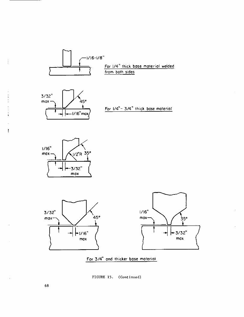
1116-118"
C For I/4" thick bose moteriol welded
from both sides
For I/4"- 3/4" thick bose material
3/32"
mox'_
1/16" _
mox
For 314" ond thicker bose moteriol
FIGURE 15. (Continued)
68
the wire. (Stick-out is the distance from the end of the contact tube to the end
of the electrode wire.) The greater the stick-out, the higher will be the melting
rate. By changing the amount of stick-out, the amount of filler wire that is
melted and the size of the weld bead can be altered without changing the welding
current.
Changing the angle of the welding gun will change the shape of the weld bead.
Tilting the gun in the direction of welding (backhand techn_ue) decreases pene-
tration, increases bead width, and improves the smoothness and contour of the bead
surface. Cap passes on multipass welds may be made with the backhand technique.
With the gun tilted back away from the direction of welding (forehand technique),
penetration, though greater than with the backhand technique, still is not as
much as when the gun is perpendicular to the bead surface. Automatic welds nor-
mally are made with the gun perpendicular or with a small amount of backhand tilt.
Increasing the welding speed will decrease both penetration and bead width.
If the speed becomes too fast, undercut will occur along the edges of the bead and
there may be areas of lack of fusion. Higher travel speeds can be used when the
weld is being deposited in narrow grooves in thin material than when welding wide
joints in thick plate.
In manual GMA welding, the operator holds and manipulates the welding gun.
The important thing for the operator to remember is that the motion of the gun
along the joint must be uniform and the position of the gun with respect to the
joint must be held constant.
In shielded metal-arc welding, penetration is relatively shallow and varia-
tions in the movement of the electrode along the joint do not affect penetration
very much. In GMA welding, penetration is much greater and changes in travel
speed can have a greater effect on penetration. This can lead to burnthrough of
the joint or lack of penetration if the operator moves the torch erratically along
the joint. Motion must be as uniform as possible.
69

Thedistance betweenthe endof the torch and the joint is very important
also. In shielded metal-arc welding, changingthe distance betweenthe torch and
joint, changesthe arc length andarc voltage. In G_Awelding, the equipment
automatically maintains a constant arc length throughvariations in wire feed
speedor welding current. Thus, changingthe gun-to-workdistance will not alter
the arc length. It will changethe amountof stick-out, though. As the stick-out
changes,the melting rate or welding current (dependingon the type of equipment)
also will change. This meansthat the beadsize or penetration also will change.
If the operator cannotkeep the gun-to-workdistance constant, the beadsize or
penetration will not beuniform.
Changesin the anglebetweenthe gun andjoint will changethe beadshape
andpenetration. Theeffect of using forehandor backhandtechniques is the same
for manualas it is for automatic _IA welding. MostmanualGMAwelding is done
using the backhandtechnique. This techniqueallows the operator to see the weld
crater better andproduceweldsof moreconsistent quality.
Thesameprecautions shouldbe exercised in protecting the undersideof the
weld joint in GMAwelding as in GTAwelding. Groovedcopperbackupstrips and
inert-gas backingmayalso be usedwith GMAwelding. In makingmultipass welds,
maximumquality is obtained by grinding out the undersideof the root passand
rewelding from that side. Rootpassesare subject to various defects suchas in-
completepenetration andlack of fusion. By grinding out the root pass to sound
metal andrewelding, these defects canbe eliminated from the finished joint.
Precautions. Theprecautions to be observedin GMAwelding of
precipitation-hardening stainless steels are concernedwith both the equipment
and the welding procedure.
EquipmentPrecautions. SuccessfulGMA welding depends on feeding
the electrode wire through the gun at a precise and uniform speed. This means
that the equipment must be kept in good operating condition. Most problems with
70

GMAwelding equipmentmaybe traced to a wire-feeding systemthat hasnot been
kept clean and in goodcondition. A well kept scheduleof preventive maintenance
of this systemplays a major role in successful GMAwelding. Important points to
check in sucha scheduleare:
(I) Adjustmentof wire-straightening rolls (if so equipped). Improper
adjustmentcan causethe wire to bendas it exits from the contact tube
and the arc will not be properly positioned in the weld joint.
(2) Alignmentof the wire with the groovein the feed rolls. Misalignment
will causebendingof the wire. Thewire also mayclimb out of the
groovewith resulting erratic wire feeding.
(3) Feedroll clampingpressure. If the pressure is too light, slippage
and erratic feedingwill result. If the pressure is too heavy, the
wire maybe deformedto the point where it will not pass freely through
the contact tube.
(4) Thewire-feed cable betweenthe wire reel andthe feed rolls shouldbe
clean and free of kinks. Dirt in the cable can be transferred to the
wire andultimately to the weld metal. A buildup of dirt in the cable
andkinks in the cable can restrict free movementof the wire through
the cable. As a result, wire feed maybecomeerratic.
(5) Thesizes of the wire feed cable, feed rolls, and contact tube should
matchthe size of the electrode wire beingused. If anyof these parts
are of the impropersize, the wire will not feed smoothly. If the
contact tube is too large, poor pickup of the current will occur. The
equipmentmanufacturerssuggestionsshouldbe followed regarding proper
sizes of these parts.
(6) Distancebetweenwire feed rolls and contact tube or wire feed cable.
This distance shouldbe as short as possible. In this area, the wire
is unsupportedand if this distance is large, the wire maybuckle.
71

(7) Windingof the electrode wire on the spool or coil. If the wire becomes
loose on the spool or coil as it feeds, loops of wire maybecomeen-
tangled stopping feeding of the wire. Mostmountingspindles for wire
spools or coils are equippedwith friction devices that apply a small
amountof tension to the wire as it feeds. This prevents looseningof
the wire. Care shouldbe taken whenmountingthe wire spool or co_l
that entanglementof the wire doesnot occur.
Theoperator shouldcheck the gaspassagesand gas-shielding nozzle periodi-
cally to be sure that the flow of shielding gas is not being disrupted. Spatter
tends to build up on the inside of the nozzle. If this buildup becomestoo great,
proper shielding cannot be obtained. Thus, the inside of the nozzle shouldbe
cleanedperiodically.
Contact tubesmaybe another sourceof trouble. Contact tubes are madefrom
copperor copperalloy and being softer than the welding wire, tend to wear from
the passageof the wire through the tube. This enlarges the baseof the tube,
which, in turn, can causeerratic current pickup. Contact tubes shouldbe re-
placedperiodically to maintain goodcurrent before wearbecomesso great that
problemsoccur.
ProcedurePrecautions. The quality of the weld joint also depends
on the welding proceduresthat are used. Slight variations in procedurecanhave
major effects on the quality of (_MAjoints in precipitation-hardening stainless
steels. Themost frequently encountereddefects andtheir causesare discussed
in the following paragraphs.
Burnthroughand excessivepenetration canbe causedby putting too muchweld-
ing heat into the joint. Thewelding current shouldbe decreasedor the travel
speedincreased. Penetration will be decreasedby tilting the gun toward the
direction of welding (forehand technique). This defect also maybe causedby
excessiveroot openingor too small a root face. If the joint dimensionscannot
72
be changed,the use of a copperbackupbar or a weavingtechnique canhelp to
prevent burnthrough.
Lack of penetration is causedby the opposite conditions to those that cause
excessivepenetration. Thewelding current maybe too low or the travel speed
too high. Thegunmaybe at too large an angle with the weld joint (either back-
handor forehand). Straightening up the gunangle will increase penetration.
Increasedroot openingmaybe needed. Theposition of the arc in the weld puddle
also will affect penetration. Thecloser the arc is to the front of the puddle,
the greater will be the amountof penetration.
Overlap occurswhenthe weld metal doesnot fuse to the basemetal at the
edgesof the top "surfaceof the joint. Usually, it is causedby carrying a weld
puddlethat is too large. Reducingthe wire-feed speedor increasing the travel
speedwill help to correct this problem. Another solution is to use a slight
weaveso that the arc will cover all areas of the weld joint wherefusion is
desired. Keepingthe arc at the front of the puddlewill improvefusion and
reduceoverlap.
An unfilled groovealong the edgeof the weld beadis called undercut.
Decreasingthe travel speedwill help to fill up these grooves. Theuse of an
argon-oxygenshielding-gas mixture will reduceundercut. However,oxygenshould
not be used in the shielding gas for welding precipitation-hardening stainless
steels that contain aluminum.
"Wagontracks" mayoccur in multipass welding. It is the namegiven to a
line of voids that are trapped at the edgesof the underlying beadwhenthe sub-
sequentbeadis deposited. This defect only showsup on an X-ray photographof
the joint whenthe line of voids has the appearanceof wagontracks on a dirt road.
Wagontracks canoccur if the lower weld beadis too high crowned. Theuse of
argon-oxygenshielding gaswill improvethe shapeof the weld beadsurface. Bead
shapealso canbe altered by adjusting the arc voltage and travel speed. Care
shouldbe usedwhendepositing the secondpass to be sure that the are melts the
entire surface of the underlying bead.73

Applications. Procedureshave beendevelopedfor _ welding of
PH15-7Moat Ling-Temco-Vought(Ref. 28) for possible application in hydrofoil
or ground-handlingequipmentfabrication. Sheet0.160 and0.210 inch thick was
weldedusing a square-butt joint. Suggestedwelding conditions were:
Voltage, voltsCurrent, ampsTravel speed, ipmTorch gas flow, cfhBackupgas flow, cfh
0.160-inch-thick sheet
0.210-
inch-thick sheet
34 34
370 370
41 30
60 (argon + I percent oxygen)
25 (argon)
PH 15-7 Mo filler wire 1/16 inch diameter was used. PH 13-7 Mo filler wire also
could be used and in certain cases, might prove better than PH 15-7 Mo because a
better metallographic structure would result.
74

Submer_ed-Arc Welding. Submerged-arc welds with properties comparable to
those of the base metal can be produced only in AM-350 and AM-355. Low-strength
nonheat-treatable welds can be made in the aluminum-bearing alloys. The minimum
thickness of steel that is welded without providing some method of backing-up the
weld is about 1/2 inch. There is no limit on the maximum thickness. Plate several
inches thick is commonly welded by submerged ar.
Submerged-arc welding can be used only in the flat or horizontal positions.
Recent developments indicate that submerged-arc welding of vertical joints is
feasible. However, no work has been done on the vertical submerged-arc welding of
precipitation-hardening stainless steels. The deep penetration inherent with
submerged-arc welding can cause difficulties when welding metal less than about
1/2 inch thick. The joint must be backed up with a copper bar or a pad of flux
to prevent melting through the joint. It is difficult to track the Joint when
welding manually since the arc and electrode end are buried under the flux blanket.
In multipass welding, the slag from the previous pass must be carefully and com-
pletely removed to prevent slag inclusions or entrapment in subsequent passes.
Equipment. The choice of power supply depends largely on the work
to be welded. D-C permits fast arc starting, gives good control over the weld
bead shape, and provides quick current buildup at the start of the weld which is
advantageous when making short welds. Best control of the bead shape and deepest
penetration are obtained with d-c reverse polarity (electrode positive), while the
highest welding speeds and shallowest penetration are obtained with d-c straight
polarity (electrode negative). The use of a-c current provides a degree of penetra-
tion in between that of d-c straight and d-c reverse polarity. A-C current also
cuts down on arc blow (the swerving of the arc from its normal path due to
magnetic forces) which can become a severe problem when very high welding cur-
rents are used.
75

Filler wires and a flu_ have been developed for welding AM-350 and AM-355
(Ref. 7,26). The filler wires are standard AM-350 and AM-355 wires used for
GMA welding. The flux has been specially formulated, but it is available
commercially. The use of this special flux and the standard wires produces
weld deposits that match the base metal composition very closely. Conventional
stainless steel fluxes should not be used for welding AM-350 or AM-355 because
the composition of the weld metal will be altered to the point where proper heat
treatment response cannot be obtained.
Fluxes for welding the aluminum-bearing precipitation-hardening stainless
steels are not available. However, submerged-arc welds can be made in these
steels, provided high-strength weld joints are not required (Ref. 14). For such
applications, ER308, ER310, or ER316 austenitic stainless steel filler wire can
be used with the appropriate stainless steel flux. The resulting weld deposit
will not be heat treatable and will not have strength as high as the base metal.
Typical designs for butt and fillet joints are shown in Figure 16. Greater
penetration is obtained with submerged arc welding than other arc-welding proc-
esses. Care must be taken not to melt through the joint when depositing the
root pass. Frequently, the root pass is deposited by shielded-metal-arc welding
and the joint then is filled by submerged are welding.
Welding Procedures. Welding conditions for welding AM-350 and AM-355
must be very carefully controlled (Ref. 7, 27). This is because slight variations
in arc voltage, current, or travel speed can cause changes in the chemical compo-
sition of the weld metal. When such variations occur, the amount of flux being
and
melted will change/the amount of alloying elements picked up from the flux by the
weld metal will be altered. Since correct heat treatment response of these steels
depends on close control of the weld metal composition, close control of the weld-
ing conditions is required. However, these conditions will change with the
application, joint design, material thickness, etc. This means that the pro-
cedure should be qualified for the particular application and that the conditions
76
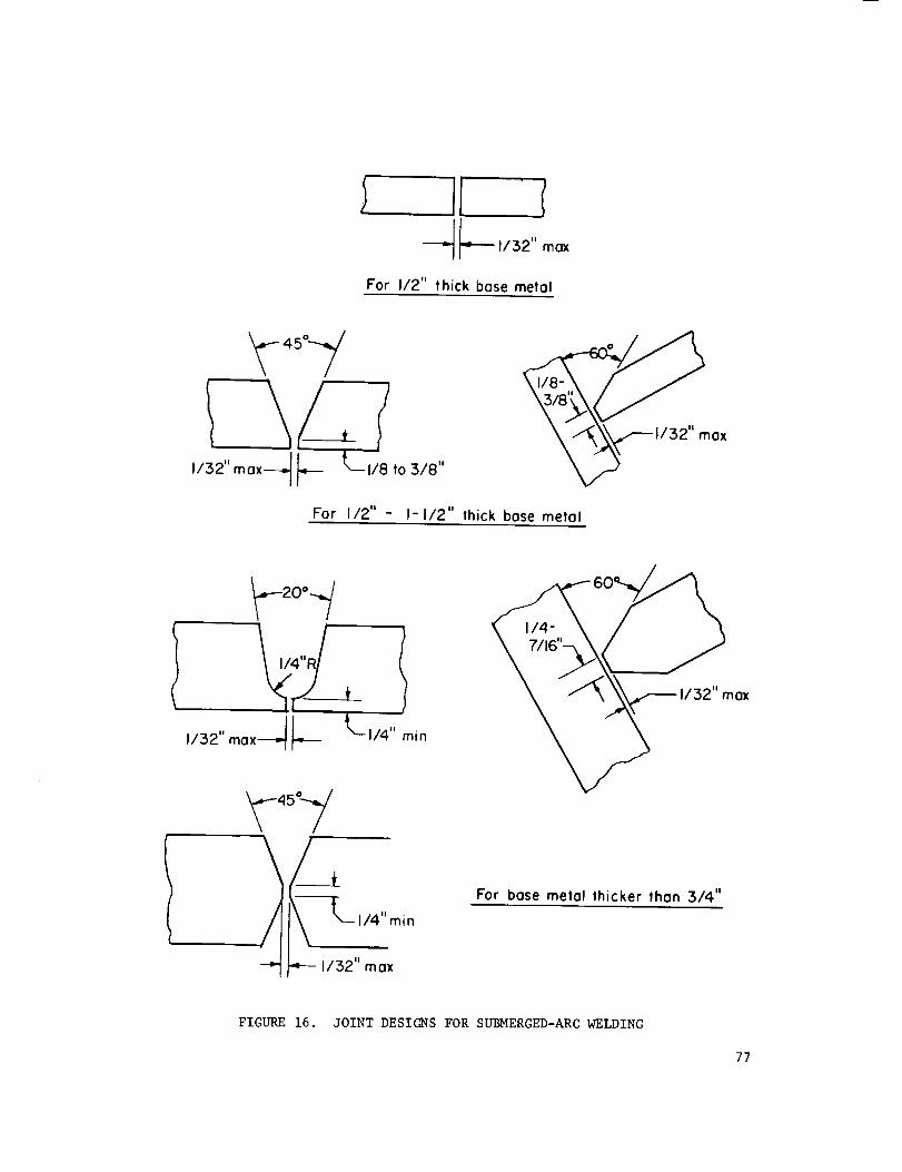
For I12" thick bose metal
'_"_°'-_I-- L,_,o_,,1/32" max
For I/2" - I-I/2" thick base metal
h_20 ° -_/
,J32,,mo,--ll--
_45_-7,
/_ ,,_"m,n--4" 1/32" max
6 ' ax
For bose metal lhicker than 3/4"
FIGURE 16. JOINT DESIGNS FOR SUBMERGED-ARC WELDING
77

must be closely monitored during welding. The wire and flux supplier should be
consulted for suggested welding conditions.
Plasma Arc Welding. The plasma arc is one of the newly developed methods
of arc welding. While the plasma arc closely resembles the gas-tungsten arc, there
are important differences that affect arc behavior and properties. The gas-
tungsten arc is an unconfined arc. In contrast, the arc column of the plasma
arc is constricted as it passes through the nozzle orifice; its diameter is
decreased, the current density is increased, and the arc temperature is increased.
Plasma-arc equipment has been developed specifically for welding. The most recent
innovation is the "needle arc", a small diameter-plasma arc that can be used to
weld foil gage materials.
Because of the arc constriction and the relative stiffness of the arc
column, the plasma arc is concentrated on a small area on the workpiece. As
a result, the following characteristics are associated with plasma-arc welding:
(I) For a given current more heat is transferred to the workpiece
with the plasma arc than with the more diffused gas-tungsten
arc.
(2) Welding can be conducted at higher rates with the plasma arc.
The weld bead and associated heat-affected zone are narrow.
(3) The plasma arc is relatively insensitive to minor variations
in the process variables.
(4) Piercing or "keyholing" of the workpiece occurs during welding.
The occurrence of piercing is a positive indication of full
penetration.
(5) Welds can be made without backup fixturing.
For welding the plasma arc is established between the electrode and the
workpiece to obtain maximum heat transfer.
Applications. At the time of this report, there was no information
on the use of plasma-arc welding for joining the preclpitation-hardening stainless
78

steels. However,they canprobably be weldedin accordancewith the conditions
established for welding the 300 series of stainless steels (Refs. 18, 39). The
following data maybe usedas a guide:
TABLEXVII. PLASMA-ARCWELDINGCONDITIONSFORSQUAREBUTTJOINTSIN TYPE304 STAINLESSSTEEL(REF.40)
StraightPolarity,Direct Arc Shielding(1 )
Thickness, Welding Speed, Current, Voltage, Gas Flow,
inch ipm amperes volts cfh
3/32 38 160 31 35
1/8 24 145 32 35
3/16 16 165 36 45
1/4 14 240 38 50
(i) Shielding gas composition: Argon + 7.5% Hydrogen.
Electron-Beam Welding. Electron-beam welding can be an attractive
process for welding precipitation-hardening stainless steel parts. The process
can be used for welding material with thicknesses ranging from the foil gages to
over 2 inches in a single pass. In addition to being very versatile regarding
material thickness that can be welded, electron-beam welding has two other major
advantages: (I) welding is done in a vacuum and (2) very narrow welds are pro-
duced. By welding in a vacuum, contamination from gaseous impurities is virtually
nonexistent. The vacuum atmosphere is even purer than the inert-gas atmosphere
of GTA or GMA welding. The very narrow welds that are produced are subject to
very little distortion or warpage°
The requirement for welding in a vacuum is also one of the chief disad-
vantages of electron-beam welding. All the parts being welded must be placed in
a vacuum chamber. The chamber size thus limits the size and shape of the parts
being welded. Movement of the parts during welding and observation of the welding
79

operation also are hinderedby the vacuumchamber. Loadingandunloading parts from
the chamberand pumpingthe vacuumon the chamberafter eachloading operation is
time consuming. As a result, production rates for electron-beamwelding are quite
low. Sliding vacuumchamber_havebeendevelopedto alleviate this problemand
work currently is underwayto develop"out-of-vacuum"electron-beamwelding.
Theother major disadvantageof electron-beamwelding is the cost of the
equipment. Electron-beamwelding equipmentis expensive. Unlessthe special
characteristics of electron-beamwelding are required, it is cheaperand usually
quicker and easier to use oneof the moreconventionalwelding processes.
Electron-beamwelding equipmentis classed as either high-powerdensity or
low-powerdensity. Only the high-power-densityequipmentis capableof producing
deepnarrowwelds. Low-power-densityequipmentwasproducedin the early daysof
electron-beamwelding developmentbut, as far as is known,no low-power-density
equipmentis being producedcurrently. However,suchequipmentstill exists and
maybe usedoccasionally by somefabricators.
High-power-densityequipmentmaybe further subdivided into low-voltage and
high-voltage classes. In low-voltage equipment,the high welding poweris achieved
by using a "low" accelerating voltage andhigh beamcurrents. Maximumvoltage ob-
tainable on suchequipmentnormally is around30 kv although some60kv equipment
is nowbeing produced. The60 kv equipmentreally shouldbe classedas medium-
voltage equipment. Thehigh-voltage equipmentusesaccelerating voltages as high
as 150kv in conjunction with low-beamcurrents.
Thereare advantagesanddisadvantagesto both high- and low-voltage electron-
beamwelding. Theprocess that is useddependson the needsof the particular
fabricator. Analmost equal numberof high- and low-voltagewelders havebeen
producedandare in use in the United States (Ref. 41).
In general, higher powercan be achievedwith the low- and medium-voltage
equipment. Mostequipmentof these classes havepowerratings in the rangeof
9 to 15 kw. (Ref. 42). Thehigh-voltage welders usually havepowerratings in
80

the 3 to 6 kwrange. Theresults obtainable with both the high- and low-voltage
high-power-densityweldersare comparable. Weldjoint shapeproducedby both classes
is comparable. Thelow-voltagewelders haveslightly greater penetrating ability
due to their generally higher powerratings. The60 kwwelder is claimed to be
capableof penetrating 9-inch aluminumplate in a single pass. Thehigh-voltage
welders generally are better suited for welding thin material and small parts.
This is becausethe beamcanbe accurately focusedto a smaller diameter than the
low-voltage beam. High-voltagewelders are equippedwith optical viewing devices
that enable the operator to observethe welding operation. Thehlgh-voltage
electron beamhas a greater depth-of-focus than a low-voltage beam. This means
that the part can be located further from the gun, up to 24 inches away. In low-
voltage welding, the part mustbe about 3 to 6 inches from the gun. However,
recent advancesin equipmentdesign permit parts to be weldedat greater distances
from the gun. Changesin shapeof the part do not affect the welding operation in
high-voltage welding while the beammustbe refocusedwhenwelding variable shape
parts in low-voltage welding.
WeldingProcedures. Weldingproceduresusedin electron-beamwelding
are dependenton material thickness and the type of electron gun being used. For
a given thickness of material, various combinationsof accelerating voltage, beam
current, and travel speedare satisfactory. In electron-beamwelding,the electrical
parametersdo not adequatelydescribe the heat-input characteristics of the beam
since these characteristics are affected significantly by the focus of the beam.
Measurementsof beamdiameterare difficult to makeunderproduction conditions
so that the transfer of welding parametersbetweendifferent equipmentunits is
very difficult. Fortunately, suitable welding parameterscan generally be developed
on a given piece of equipmentwith only a very few trials.
In very thick material, the first passmadeto completelypenetrate the joint
sometimesis undercutalong both edgesof the weld metal. This undercutting canbe
81

TABLEXVIII, TYPICALCONDITIONSFORELECTRON-BEAMWELDINGPRECIPITATION-HARDENINGSTAINLESSSTEELS(Ref. 41)
Material
Beam Travelthickness, Voltage, Current, Speed,
inch kv ma ip_ Remarks
0.032 90 2.5 300.046 120 3 58.50.i00 i00 i0 300.125 125 5 300.625 140 8 25.4
0.050 120 4 70
0.250 145 15 460.500 150 18.5 14 Bead-on-plateweld0.750 150 20 201.000 150 40 28
PH15-7 Mo 0.150 150 5.5 27 O.060-inchlongitudinalbeamoscillation
0.004 50 0.3 30 Lap joint0.250 145 ii 28 0.010-inch circular beam
oscillation0.645 150 17.5
7-4 PH
.7-7 PH
AM-355
I0
82

eliminated by a secgnd weld pass made at somewhat lower energy levels with a
slightly defocused beam. However, undercutting frequently can be reduced by
making minor adjustments in travel rate. The underside of electron-beam welds
also may exhibit an undesirable contour. Some type of metal-removal operation
is generally required to produce an acceptable underside contour.
The flat welding position usually is used in electron-beam welding. The
welding positions that can be used are limited by the versatility of the avail-
able welding equipment. Table XVIII shows some of the welding conditions that
have been used in the electron-beam welding of precipitation-hardening stainless
steels.
Applications. Electron-beam welding has been investigated exten-
sively for joining PH 15-7Mo parts for the XB-70 (Ref. 43). Sine-wave parts
were welded to brazed honeycomb panels (Figure 17) and then these panels were
welded together (Figure 18).
In welding the spar to the panels, the part was placed so that the spar was
in a horizontal position. In this position, the electron beam, being in the
vertical plane, did not "see" a sine-wave joint but a straight T-joint that
varied up and down in the vertical plane. The beam was focused at about the mid-
point of the sine-wave height and then traversed the joint. A high-voltage beam
with a broad depth-of-focus was used so that no further adjustment of the focus
was required as the weld was made. In welding the panels together, the beam was
directed at the top joint of the upper honeycomb panel. The beam penetrated the
top and bottom face sheets of the top panel and the top and bottom sheets of the
lower panel. Thus, all four joints were made simultaneously.
Techniques and equipment were developed for making the final close-out weld
on the wing to fuselage joint on the XB-70. This joint is shown in Figure 19. The
bottom face sheet of the brazed PH 15-7Mo honeycomb panel was GTA welded. The
GTA torch was positioned through a gap in the upper face sheet. After GTA welding,
83

FIGURE17. SINEWAVESPECIMENINPH15-7 MoSTAINLESSSTEEL(Ref. 43)
FIGURE18. SIMULTANEOUSFOURWELDSPECIMENINPH15-7MoSTAINLESSSTEEL(Ref. 43)
84

Panel face sheets
\
_--"_Honeycombcore
Electron beam weld
I, J)
f
arc weld (keyholemethod)
FIGURE 19. WING-TO-FUSELAGE JOINT IN XB-70 (Ref. 43)
85

this gap was filled with a T-shaped filler strip. A portable electron-beam welder
was clamped over the joint area on the upper sheet and an electron-beam weld was
made along each side of the filler strip (Figure 20).
The portable welder that was developed consists of a small half-shell-type
vacuum chamber that clamps on the part to be welded. The part being welded (which
must be large and flat) forms the bottom half of the chamber. The electron gun
is mounted on a lid that slides along the top of the chamber (Figure 21). The
equipment can be used for overhead welding of large parts also (Figure 22).
Other precipitation-hardening stainless steel parts that have been fabricated
by electron-beam welding include a 17-7 PH pressure vessel and an A-286 turbine
wheel. The pressure vessel (Figure 23) (Ref. 24) was 8-inch diameter with 0.140-inch
wall thickness. This part illustrates an excellent application for electron-beam
welding. Jigging of the pressure vessel is simple and there is no requirement for
internal backing strip or clamps. Thus, the problem of removing internal parts
does not present itself and a large exit hole is not required. The turbine wheel
consisted of an A-286 turbine disc and a ring of Udimet 500 blades. Electron-
beam welding has proven to be an excellent method of joining certain dissimilar
metals or alloys and this is a typical example of such an application.
Resistance Spot Welding. In resistance spot welding, all the heat required
to accomplish joining is supplied by the passage of an electric current between two
opposed electrode tips that contact the surfaces of the parts to be joined. In con-
ventional spot-welding practice, a localized volume of metal at the sheet-to-sheet
interface region melts, then solidifies to form the weld.
Resistance spot welding has been applied to a limited number of the precipitation-
hardening stainless steels such as 17-7 PH, A-286, PH 15-7 Mo, PH 14-8 Mo, AM-350,
and AM-355. but information on applications, welding conditions and techniques, and
properties is limited. Alloys such as 17-4 PH, 17-10P, HNM, and AFC-77 are not
widely used for applications requiring spot welding. When spot welding the
86

FIGURE 20. PHOTOMACROGRAPH OF SIMULATED WING-TO,.FUSELAGE WELD
(Ref. 43)
FIGURE 21. PORTABLE ELECTRON-BEAM WELDER
(Ref. 44)
87

FIGURE 22. PORTABLE ELECTRON-BEAMWELDER SET UP FOR
OVERHEAD WELDING OF LARGE PARTS
(Ref. 44)
88

|
!
m
I IIII
FIGURE 23. ELECTRON-BEAM WELDED PRESSURE VESSEL
(17-7 PH STAINLESS STEEL,
0.140-1NCH WALL THICKNESS)
(Ref. 24)
89

precipitation-hardening stainless steels, welding conditions are based on those
used for the austenitic stainless steels. For best welding results with alloys
like 17-7 PH and PH 15-7 Mo, welding just before or just after the final harden-
ing treatment is usually recoFnmended. This procedure leaves the spot weld nugget
in a softer, tougher condition than the base metal.
The configurations involved in spot welding and the relatively short-time
periods used with the process tend to preclude any contamination from the atmos-
phere. As a result, there appears to be little need to consider auxiliary
shielding during resistance spot welding. The thermal and electrical conducti-
vities, and mechanical properties of the precipitation-hardening stainless steels
vary, depending on the alloy and its condition. Conditions for spot welding,
therefore, are adjusted to account for the material properties as with other
materials. Usually, several combinations of welding variables can produce similar
and acceptable results.
Equipment. Precipitation-hardening stainless steels have been
welded successfully using conventional resistance spot-welding equipment (Ref. 45).
Spot-welding equipment normally provides accurate control over the basic spot-
welding parameters: weld current, weld time, and electrode force. Various data
indicate that each of these parameters may vary to a certain degree without ap-
preciably reducing weld quality. It is, however, desirable to have enough control
over the parameters to obtain reproducible results, once the optimum settings are
obtained for a given application. Because of the higher currents and electrode
forces required for thicker sheet and for the harder alloys, the larger press-type
machines are more suitable. Upslope controls are used to help prevent expulsion,
but downslope and postweld heat controls have not demonstrated any advantages
when used in welding these alloys. No significant changes in welding characteris-
tics or static weld properties have been reported that can be attributed to the
use of any specific type of resistance-welding equipment, but there may be a
preference by some fabricators for three-phase equipment.
90

RWMAGroupA Class 3 electrode alloy generally is usedfor spot welding
precipitation-hardening stainless steels. In conventional practice, internally
cooledelectrodes are recommendedto improvetip life. For small parts, the
electrodes often are not water cooled. Both flat face and spherical radius tip
geometriesare used.
Whendesigning sheet-metalassembliesfor resistance spot welding, the
factors that should be consideredare the sameas for other materials. These
factors include:
(I) Joint Overlap- A sufficient amountof overlap shouldbe provided to
contain the weld.
(2) Accessibility - Spot welds shouldbe placed in locations that are ac-
cessible with the equipmentto be used.
(3) Flatness - Forging pressurewill be inadequateif part of it is used
to form the parts to provide proper contact.
(4) WeldSpacing- Insufficient spot weld spacingcausesreducedcurrent at
the desired location due to shunting to somecurrent through previously
madewelds.
WeldingConditions. Resistancespot-welding conditions are primarily
controlled by the total thickness of the assemblybeing welded, and to a rather
large degree, by the welding machinebeing used. Similar welding conditions may
be perfectly suitable for makingwelds in the sametotal thickness wherethe number
of layers differs significantly. However,for any given thickness or total pileup,
various combinationsof welding current, time, and applied force mayproducesimilar
welds. Other variables suchas electrode size and shapeare important in con-
trolling suchcharacteristics as metal expulsion, sheet indentation, andsheet
separation.
Theprecipitation-hardening stainless steels generally are harder and stronger
than low-carbonsteel, particularly at elevated temperatures;greater pressures
are therefore required during spot welding. Thetime of current flow shouldbe
91

as short as possible. Current is set at a value that is somewhatabovethe
value that producesa weekor just "stuck" weld, but belowvalues that produce
expulsion.
Properties. Thequality of spot welds is determinedby several
testing methods. In addition to cross tension and tension-shear-strength
requirements,manyspecifications, suchas companyspecifications and the
military specification MIL-W-6858(Ref. 46), place certain restrictions on
weld penetration, sheet separation, electrode indentation, andweld diameter.
Manyproperties and characteristics of resistance spot welds in pre-
cipitation-hardening stainless steels havebeendetermined. In manyinstances,
complextesting proceduresare required to determinethe behavior of spot welds
under special conditions. Thefatigue properties of spot welds are low, but
this behavior is morecharacteristic of the joint type than of the material.
Applications. Resistancespot welding has beenusedextensively for
fabricating someof the precipitation-hardening stainless steels, andconsiderable
information hasbeendevelopedon spot welding these alloys. Someof the
precipitation-hardening stainless steels have not beenso widely usedin sheet
form, so the information available on spot welding themis quite limited.
AM-350,AM-355,AM-362,andAM-363alloys are spot weldedusing conditions
similar to those usedfor austenitic stainless steels (Ref. 47). Thesealloys can
be spot weldedbefore or after the final hardening treatment. However,spot welding
AM-350before the transformation treatment can result in low strength andbrittle
failures (Ref. 48). To obtain tension-to-shear ratios greater than 0.25, it is
recommendedthat the aging treatment precedethe welding operation. Strengthsof
spot-weldedAM-350andAM-355are shownin Table XIX. Theeffects of various heat-
treating cycles on the tension-to-shear ratio of spot-weldedAM-350are shownin
Table XX. Thetensile-shear strengths at elevated temperaturesof various thicknesses
of spot-weldedAM-350are shownin Figure 24. AnAM-350spot-weldedstrap hinge is
shownin Figure 25. Spotwelds also have beenmadeto join AM-350to 17-7 PH. Thetensile-shear strengths of these welds were very similar to those in AM-350.
92

TABLEXlX. TENSION-SHEARSTRENGTHSOFSPOT-WELDEDAM-350ANDAM-355STAINLESSSTEELS(Ref. 47)
HeatTreatmentCondition(a)
Electrode Electrode Weld Welding Tension-ShearDiameter, Force, Time, Current, Strength,
inch pounds cycles amperes pounds
0.024-1nch-Thick AM-350
+ welded 5/32 1200 12 8,500 1090
1/4 1200 24 10,500 1275
+ welded 5/32 1200 12 7,500 1020
1/4 1200 12 9,500 1440
C + welded 5/32 1200 12 7,500 1030
1/4 1200 12 9,500 1260
O.037-1nch-Thick AM-355
A + welded 1/4 900 I0 9,500 1810
14 9,500 1900
B + welded 1/4 900 i0 9,500 1850
14 9,500 2500
C + welded 1/4 900 i0 9,500 1410
14 9,500 1940
Welded + D I/4 900 I0 9,500 1840
14 9,500 2140
Welded + E I/4 900 I0 9,500 2480
14 9,500 2080
Welded + F 1/4 900 i0 9,500 1780
14 9,500 2240
(a) Code
A
B
C
D
E
F
Heat Treatment
Mill annealed at 1750 F
Mill annealed; -i00 F for 2 hours; 850 F for 2 hours
Mill annealed; 1375 F for i hour; air cool; 850 F for I hour
-i00 F for 2 hours; 850 F for 2 hours
1710 for 15 minutes; air cool; -I00 F for 2 hours; 850 F for 2 hours
1375 for i hour; air cool; 850 F for I hour.
TABLE XX. EFFECT OF HEAT TREATMENT ON TENSION-TO-SHEAR RATIOS OF SPOT-WELDED
O.080-1NCH-THICK AM-350 STAINLESS STEEL (Ref. 47)
Strength, pounds Tension-Preweld Heat Postweld Heat Tensile-Shear Cross-Tension to-Shear
Treatment Treatment Test Test Ratio
_nneal (1720 F) None 7475 2575 0.34
_nneal (1720 F) SCT 8725 2100 0.24
SCT None 7450 3060 0.41
SCT SCT 8710 2550 0.25
93

14,000
_o oo
.E _ooo
BOO0
6000
I
c 4000---
2000
DI00
Sheet size, in.
---_...tL_._,oo.,__ _ ,--_..._.<
i 0.050 to 0080(
0.030 to 0.050I ]
500 600 700 8OO
Tesl Temperoture, F
FIGURE 24. TENSILE-SHEAR STRENGTH AT ELEVATED TEMPERATURES
FOR SPOT-WELDED AM-350 STAINLESS STEEL
(Ref. 47)
Material in SCT heat-treated condition prior to
welding. No postweld heat treatments given.
94

FIGURE 25. STRAP-HINGE OF AM-350 USED TO
FASTEN CANISTERS OF DELICATE
INSTRUMENTS IN THE
ATLAS MISSILE
(Ref. 49)
95

Spotwelding wasusedto fabricate light weight AM-355rocket chambers
strong enoughto withstand 305,000psi wall stress (Ref. 50). Thesechambers,
shownin Figure 26 and 27, were fabricated by "strip winding" and spot welding
multiple layers. This methodof fabrication wasusedas a replacementmethodfor
brazing andresin bonding. Brazing introduced extra weight and the high brazing
temperaturesweakenedthe parent metal. Resin-bondedlayers separatedwhensubjected
to aerodynamicheating.
Slightly higher spot welding currents are required for Almar363 than for
the austenitlc stainless steels becausethe material is magnetic(Ref. 51). The
spot weldedstrengths increasewith the weld diameter in the samemanneras the
austenitic stainless steels. Figure 28 illustrates the weld strengths which are
well abovethe AWSminimumvalues of 2400pounds. Thetransportation industry
usesspot welding extensively to fabricate Almar363. Its high strength makesit
attractive for the structural frameworkin applications suchas shipping containers,
railroad cards, and trailer truck bodies. Figure 29 showsthe joining of AISI
201truck panels to "hat" shapedstructural frameworkwhich is madeof Almar363
steel.
Armco17-7 PH, PH14-8 Mo, and the PH15-7 Moalloys also havebeenfabricated
into useful products by spot welding. Typical recent applications of spot welding
Include rocket chambersanda variety of assemblyoperations on the XB-70andother
type aircraft. Weldingconditions for these alloys also are similar to thoseused
for the austenitic stainless steels. For best spot welding results, it is recom-
mendedthat spot welding be performedjust before or after the final hardening
treatment. This procedureproducesa spot weld nugget that is in a tough austeni-
tic condition (Ref. 52. Thesealloys canbe spot weldedreadily to satisfy the
requirementsof MIL-W-6858(Ref. 52, 53, 54).
Typical welding conditions and properties of spot welds in 17-7 PHare
given in TableXXI. Thesedata showthat acceptablespot weldscan be produced
96

FIGURE 26. WRAPPING AM-355 FOIL ONTO A MANDRELWHERE IT IS TACK WELDED INTO
POSITION PRIOR TO SPOT WELDING
(Ref. 50)
97

FIGURE 27. RESISTANCE SPOT WELDING A NEW AM-355 CASE
(Ref. 50)
98

48
0 440
..c4" 40¢-
_ 36
¢-
!r"0"N 32I-(1)
I.--
28 _ A
/
/
Pulled nugget
Ex
11,600 amp
15,200 amp
I
Prk--""
pulsion
i
AWS min strength for 0.220"diam weld in 0.060"material w
is 2400 Ib
0.20 0.24 0.28
Weld Nugget Diameter, inches
0.32
FIGURE 28. TENSION-SHEAR STRENGTH FOR SPOT WELDS IN
0.060-1NCH-THICK ALMAR 363 (Ref. 51)
99

FIGURE 29. ALMAR 363 STRUCTURAL MEMBERS BEING SPOT WELDED
TO TYPE 201 STAINLESS STEEL PANELS (Ref. 51)
i00

TABLEXXI. RESISTANCE-SPOTWELDINGCONDITIONSANDPROPERTIESFORSPOTWELDSIN17-7 PHPRECIPITATION-HARDENINGSTAINLESSSTEEL(Ref. 52)
F ,
Average
Tension-
Condition Condition Shear
Thickness, In Which In Which Force, Time, Current, Strength,
inch Welded Tested Ib cycles amperes ib
0.050/0.050 A RH950 1200 I0 7500 2556
0.050/0.050 R-100 RH950 1200 I0 7500 2882
0.050/0.050 RH950 RH950 1200 I0 7500 26660
0.050/0.050 A THI050 1200 8 8700 2990
0.050/0.050 A THI050 1200 I0 8700 2790
0.050/0.050 A THI050 1200 12 8700 2680
0.050/0.050 A THI050 1400 i0 8700 2870
0,050/0.050 A THI050 1600 I0 8700 2730
0.050/0.050 A THI050 1800 12 8700 2900
0.050/0.050 T THI050 1200 I0 7500 2970
0.050/0.050 T THI050 1200 12 7500 3250
0.050/0.050 T THI050 1400 I0 7500 2790
0.050/0.050 T THI050 1600 i0 7500 2710
0.050/0.050 T THI050 1800 12 7500 2980
0.050/0.050 THI050 THI050 1200 I0 7500 2610
!0.050/0.050 THI050 THI050 1200 12 7500 2747
0.050/0.050 THI050 THI050 1400 i0 7500 2620
0.050/0.050 THI050 THI050 1600 i0 7500 2550
0.050/0.050 TH1050 TH1050 1800 12 7500 2700
i01

in 17-7 PHwith a variety of material andwelding conditions. Spotwelding of a
typical 17-7 PHaircraft componentis shownin Figure 30 (Ref. 55).
ThePH14-8 Moalloy also canbe spot welded (Ref. 14). Weldingschedules
developedfor PH14-8 Mo, a candidate skin material for supersonictransport air-
craft, are recorded in Table XXII (Ref. 56). Thealloy wasspot weldedin the
annealedcondition and in the heat-treated condition. Specimensmadefrom heat-
treated material were tested in the as-weldedcondition, and specimensmadefrom
annealedmaterial wereheat treated after welding. Thepostheat treatment was
as follows: Trigger annealedat 1700F for I hour andair cooled, then sub-zero
cooled at -ii0 F for 8 hours, and then agedat 1050F for i hour.
ThePH15-7 Moalloy also canbe spot weldedreadily (Ref. 53). Properties
obtained for spot weldspreparedin intermediate stagesduring heat treatment
to the standard conditions TH1050, RH950, andCH900, are shownin Table XXIII.
As part of the B-70program,PH15-7 Mostainless steel wasspot weldedusing
existing certified welding schedulesfor 17-7 PH(Ref. 57). Material thickness
combinationswere 0.025/0.025, 0.025/0.040, and 0.040/0.040 inch.
A-286alloy also is readily resistance welded. Severalaircraft companies
haveexperiencedno problemswith cracking or other defects related to spot welding
this alloy (Ref. 47). Other investigators, however,haveencounteredcracking and
recommendthe use of increasedforce or downslopedwelding current as possible
remedies(Ref. 45). Another fabricator (Refs. 54_58) concludedthat the rangeof
spot welding machinesettings was found to be narrower than for stainless steels
of the 18-8 variety. Within the welding range, the alloy wasweldablewithout
flood cooling andwith less discoloration than Type321 stainless. Therewere indi-
cations that it wouldbe difficult to avoid cracking in or adjacent to the weld
nugget, especially if weldedunderrestraint. Sometypical properties for A-286
spot welds are given in TableXXIV.
102

\
FIGURE 30. SPOT WELDING ECONOMICALLY FABRICATES A LIGHTWEIGHT HIGH-STRENGTH
AIRCRAFT PART MADE OF 17-7 PH PRECIPITATION-HARDENING STAINLESS
STEEL (Ref, 55)
103

TABLEXXII. SPOT-WELDINGSCHEDULEFOR0.025/0.025-1NCHPH14-8MoSTAINLESSSTEEL(Ref. 56)
Condition Prior to WeldingHeat Annealed
Treated (as received)
Weldphaseshift, percent
Heat cycles
Cool cycles
Impulses
Transformer
Weld force, ib
ElectrodesClassDiameter, inchRadius, inch
Nuggetdiameter, inch
Penetration, percent
Averagetension shear strength, ib
Averagecross tension strength, Ib
50 36
2 3
1.5 1.5
1 2
Series Series
1,250 800
Copper CopperIII II5/8 518
3 3
0. 115 0. 115
50 30
850 765
417 448
104

TABLEXXIII. PROPERTIESOF SPOT WELDS IN PH 15-7 Mo (Ref. 53) (a)
_hick-
nes8_inch
Condition Condition Average Tension Shear
in Which in Which Strength
Welded Tested low low 3 Avg. of 20 low
Tension BreakingLoad --- ib
low 3 Avg. of 20
0.049
0.049
.040
A TH 1050 2830 2840 3103 370
T TH 1050 3075 3208 3438 1360
TH 1050 TH 1050 2530 2623 2896 1500
MIL-W-6858 Minimums 2125 2470 2620 --
A RH 950 2500 2550 2853 370
A 1750 RH 950 3115 3248 3426 --
R-100 RH 950 2945' 3105 3335 1040
RH 950 RH 950 2480 2533 2630 1890
MIL-W,6858 Minimums 2125 2470 2620 --
C CH 900 2545 2625 2648 740
CH 900 CH 900 2115 2222 2422 1040
MIL-W-6858 Minimums 1460 1700 1800 --
400 580
1392 1648
1652 2015
393 _20
.m --
1050 1232
1977 2170
767 854
1113 1264
(a) Welding conditions:
Electrode force 1200 pounds
Dome radius of electrode: 3 inches
Current: 7500 amperes
Time: i0 cycles
No postheat or forge cycle.
Vapor blasting used l_remove heat treat scale before welding.
105

0_
B
E_0
0
0_ o9
P.l m
r.._r_
u'l i
o
0 _ 0 •
J
_ aJ
_-_ _ 0
r_
•_ _
0 0 0
0 ¢'_ o_
00 u'_ 0
0 0 00 0 0
0 0 0u_ 0 0o_ 00 0
_D
(_
0 0
P_ P_
e_0
-,.t"
0
0
p_
c_
-,t"
¢M
.4"
_M
II I II I
I! I II I
_D
_J
0 0
@,/
0 _ 0
,-_ 0
,-_ 0
0u_0
O'
0
0
0
_2 C
i_ ,...1 ¢_1
,...t Or-I
-d" '-.'t ",1"
_ 0 _
_ ,d ,d
0 0 0
¢_I e,l e,l
_ o
0 0 00 0 0cr_ u'1 o_
0 0 o0 0 o
,-I ,.-I ,..-i
-.t"
o _
'4-1 '4--I U_0 0 0
P_ P_ P_
0
0
c_
0r_
o0
0
o
106

Resistance Seam Welding. Seam welding is similar to spot welding. The
principal advantage of seam welding is that it can be used to produce leaktight
Joints. The principal disadvantage is that there is much more distortion with
seam welding than with other types of resistance welding. Experience in seam weld-
ing the precipitation-hardening stainless appears to be limited to 17-7 PH.
In seam welding, wheel-type electrodes instead of spot-welding electrodes are
used. Individual overlapping spots are created by coordinating the welding current
time and wheel rotation. Seam welds can be made with conventional spot-welding
techniques. However, it is much more common to use commercially available equipment
designed specifically for seam welding. In seam welding, the wheels usually can be
rotated continually or intermittently. The use of continuous seam welding im-
poses additional limitations on the weld-cycle variations that can be used. For
example, a forge-pressure cycle is not possible during continuous seam welding
because of the continuous rotation of the electrodes. Forging pressure can be
used with intermittent motion. When the completed weldment is intended for applica-
tions requiring leaktight seams, suitable pressure or leak tests are used. In
addition, many of the tests applicable to spot welds also are applicable to seam
welds.
Applications. Seam welding is used for welding sheet metals usually
for applications requiring gastight or leaktight seams. The precipitation-hardening
stainless steels have been resistance seam welded but, unfortunately, only limited
information is available in the published literature. The available information
is further restricted to the 17-7 PH alloys. Seam welding conditions and proper-
ties for this alloy are given in Table XXV. When developing these conditions, the
best combination of surface condition and weld spacing was produced using a seam
welding speed of 25 inches per minute, 5 cycles heat time, and 4 cycles cool time.
The seam welds were very nearly free of defects except for some expulsion and
porosity near the beginning of each weld.
107

108
!p_,-4
U_
50 (U
0"_ v
0rn
0,_ cnr._ o9
l-.-t
m _
_ Z_ OZ_
O
X_
• I-i _
_ d•,-4 _ .,-4
O
•_ __ o
Ng
o O _
M
o 4-* o
4J _ -,-I•_ O ._
o _
O O _
'_J O ,--_
U .,-4.,4..c
0 0 0
un 0 0,.-4 ,-4
0-.Teq =
! ! I! I !
IrI i ,
l t II I I
..- ..
,--4
0 0 •u'% u'% "00 0 ,-_
OO,.-4
O
O
o,--4
HI--4
v

Seam welding also has been utilized for close-out joints in 2- and 3-ply
pileups of 17-7 PH with access from one side only. Satisfactory welds were pre-
pared using a serles-reslstance welding arrangement (Ref. 60). The electrode
arrangement is shown in Figure 31. Electrode force required with the series ar-
rangement was twice that required for normal seam welding.
Flash Welding. Flash welding is used extensively for joining a limited
number of precipitation-hardening stainless steels. Typical products include jet
engine rings, aircraft parts, band saws, knives, and pressure tanks (Ref. 61).
In two respects, flash welding is better adapted to the high-strength, heat-
treatable alloys than are arc, spot, or seam welding. First, molten metal is not
retained in the joint, so cast structures that might be preferentially corroded
are not present. Second, the hot metal in the joint is upset, and this upsetting
operation may improve the ductility of the heat-affected zone.
Flash welding has several important advantages. Weight saving can be realized
because there is no need for overlapping bolting, riveting, or welding flanges.
Extruded shapes can be flash welded and, with suitable designs, machining costs
can be reduced.
Equipment. Equipment for flash welding is considerably different from
equipment used for spot or seam welding. For welding, the parts are held firmly
in two copper-alloy dies. One or both of these dies are movable. Current from a
welding transformer passes through the dies and into the work. The parts initially
may or may not be separated but are advanced toward each other. At the first contact
of the parts, the current causes melting of the metal and violent expulsion. This
behavior continues until the base metal is heated to welding temperature. Then,
the parts are forged together to complete the weld. Welding current usually is
shut off at the time forging takes place.
109

Insulation
Current _.,_ .... --_._-- Upper section loop
path_ _ / _Spring-looded brush mechanism
\, -q
L1--L ,,,,-I t'l- "k.=_____-'To lowersectionloop
I t F "----J Parts be,n weld dJ II /--" g e
,, T: _ ' " _ _-- opper conducting plate
-- ,, ,, ,, .,]/ / ,. ,_ ,. ,, ,. ,; . •
In s u la tion --
Lower-__-_ _'_ _'
supportarm k_J _ __
, Adjustable brace-_"
FIGURE 31. MACHINE ARRANGEMENT FOR SERIES SEAM WELDING (Ref. 60)
ii0

The machine capacity required to weld precipitation-hardening stainless
steels does not differ greatly from that required for steel. This is especially
true for transformer capacity. The upset-pressure capacity for making flash
welds in precipitation-hardening stainless steels is higher than that required
for steel. Figures 32 and 33 show the transformer and upset capacity required
for welds of different cross-sectional areas in stainless steels (Ref. 62). Also
of importance is the fact that transformer-capacity requirements vary from one
machine to another, depending upon the coupling between the parts and transformer.
Joint Design and Joint Preparation. Joint designs for flash welding
precipitation-hardening stainless steels also are similar to those used for other
metals. Flat, sheared, or saw-cut edges and pinch-cut rod or wire ends are satis-
factory for welding. For thicker sections, the edges are sometimes beveled
slightly. The over-all shortening of the parts due to metal lost during welding
should be taken into account so the finished parts will be the proper length.
Figure 34 shows the metal allowances used in making flash welds in several materials
including stainless steels. The allowances include the metal lost in the flashing
and upsetting operations.
The flash-welding conditions that are of g_eatest importance are flashing
current, speed and time, and upset pressure and dXstance. With proper control
of these variables, molten metal, which may be conta_ninated, is not retained in
the joint, and the metal at the joint interface is at the proper temperature for
welding.
Generally, high flashing speeds and short flashing times are used when it is
desirable to minimize weld contamination. Also, the use of a parabolic flashing
curve is more desirable than the use of a linear flashing curve because maximum
joint efficiency can be obtained with a minimum of metal loss.
III

i 2600
2200
%,.
_ 1400
600
•D 200
• o_
_1__/_ _onel" titaniumI I I
_o 20- 30 40 50
Weld Area, square inches
FIGURE "32. TRANSFORMER CAPACITY VERSUS WELD AREA FOR FLASH
WELDING (Ref. 62 as corrected)
800(=
O,,%
OOo 600
U0
e-to 400
L)
n 200!
n
I
- Zd0!
= | i IO I0 20 30 40 50
Weld Area, square inches
Low-alloy, high-
Stainless steel-lnconel strength steels
20,000 to 30,000 psi 15p00 to 25,000 psiA/ _-----_
$:!:_ii :_$_:i:.i:?'_:" . ,';."i_.i_::_,1-,'-1.:..,.,,,:.1.:.1.,-.._,,.,.:,_
i(_£}i[::i:i:_NN _iiiiiiiiiii!_i_:_iiiiiiiiiii;! _-_
O
_o o
FIGURE 33. MAXIMUM MACHINE UPSET-PRESSURE REQUIREMENTS VERSUS
WELD AREA FOR FLASH WELDING (Ref. 62)
112

1.200
t,,r3
" 1.000UE
.w
0.800
0
0.6000
_- 0.400
0.2000
Add 0.030-0.120 forhand-feed allowance
,ji,,/j _ _ _"-Constant feed, ;ci,e orno,,,_ rated i_" Steel - Envelope as shown
Inconel-stainless steel-Upper portion of
l envelopel
0.200 0.400 0.600 0.800
_
Jf J
fI
Stock Thickness, inch
1.000
FIGURE 34. TOTAL METAL ALLOWANCE VERSUS STOCK THICKNESS
FOR FLASH WELDING (Ref. 62)
113
Flash-welding variables vary from machine to machine and application to
application. Welding current and arc voltage depend on the transformer tap that
is used,
Properties of Flash Welds. Flash welds that have mechanical proper-
ties approaching those of the base metals are being regularly produced in conven-
tional machines. Joint efficiencies of 95 per cent or better are common for flash
welds. The static-tension-test properties of flash-welded Joints in 17-7 PH and
A-286 are summarized in Table XXVI.
Applications. Flash welding has been used for joining preclpita-
tion-hardening stainless steels in a variety of forms and shapes. It is used for
butt welding bar, rod, and extruded sections. The process also is used for
joining rings such as jet-engine rings. A typical jet-englne ring fabricated by
flash welding is illustrated in Figure 35. These rings are fabricated by ring
rolling of extruded sections and flash welding. Some of the processing steps
used by one ring manufacturer for fabricating flash-welded rings are illustrated
in Figure 36 (Ref. 63).
Other Resistance Weldin_ Processes. The preclpitation-hardening stainless
steels have been welded by other resistance welding processes but, unfortunately,
information on welding conditions and properties is very limited. Stud welding has
been tried, and conventional methods and fluxing procedures for stainless steels
in general appear promising (Ref. 64).
Pro_ection welding also has been used for cross wire welding the 17-4 PH
alloy. Information available on this application is presented in Table XXVII (Ref.
16). Cross-wlre weldment strengths can exceed the strengths for similar welds in
Type 301 stainless steels, when the 17-4 PH weldment is properly heat treated subse-
quent to welding. The cross wire welds described in Table XXVII were made using
a 75 kva a-c-type spot-welding machine and tested in simple tension using a
special testing fixture.
114
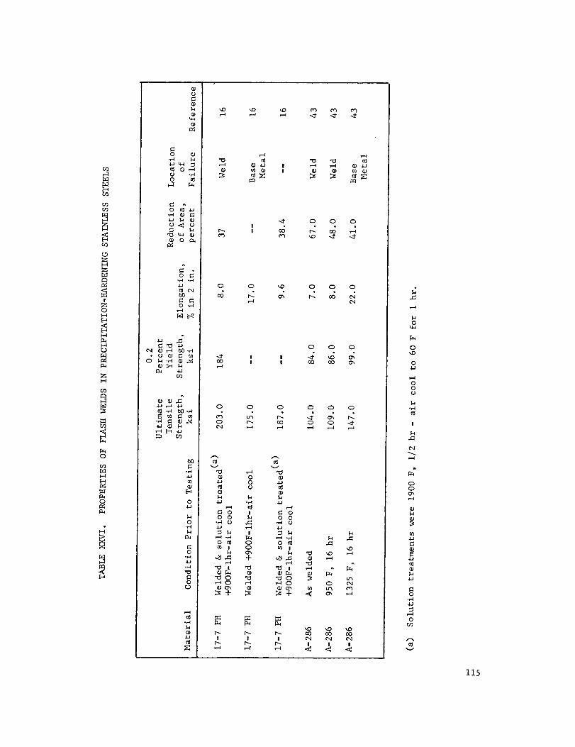
!Z0
I-Ir_
0
I-4
o
o
0 ...I
•,_ _
• o e._
o_4J_ CN
0 .,-I
_ m
o
o
0
ocO
o_.J
Q;
!
o 0 _o 0
o
J0000 !
o 0 0 0
o r_ co 0
v"0
00
o
.r.I
!
4J _.4
"_ "_ r_o tg o
o_
o_ •_o
oo_ o
¢1n_
v
oo o
4_
o
o_'_o
r._ _ r_ _! ! _xl
o3
0
0
0
,g00
0
0
_4
0t_
¢xl!
,4"
0
.4-
0
0
0
_z
_4
¢xl!
"4
0
0
0,1-1
ooo
I
4-1
4.1
0
_40
v
115

c_O
ho
04
Cross Seclion
FIGURE 35. ILLUSTRATION OF A FLASH-WELDED JET-
ENGINE RING (Ref. 56)
116
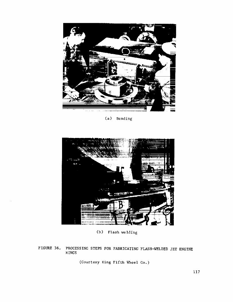
(a) Bending
(b) Flash welding
FIGURE36. PROCESSINGSTEPSFORFABRICATINGFLASH-WELDEDJET ENGINERINGS
(Courtesy King Fifth Wheel Co.)
117

(c) Shrinking
(d) Expanding
FIGURE 36. (Continued)
118

TABLEXXVII. TENSILESTRENGTHOFRESISTANCEPROJECTIONWELDEDCROSS-WIREJOINTS(Ref. 16)
AlloyName
BreakingLoadDiameter, in Tension,
inch Final Condition Prior to Testing Ib(a)
17-4 PH i/4
302 i/4
17-4 PH 5/32
Welded + 900 F - 1 hr - air cool
H900 + Welded + 900 F - 1 hr -
air cool
Weld + Solution Treated + 900 F -
I hr - air cool
H900 + Welded
Cold Drawn (UTS 160,000 psi) + welded
A + Weld + 975 F - 1 hr - air cool
A + 975 F + Weld - i hr - air cool
2,864 (bj
3,307 (b)
4,876 (bj
3,295 (b)
1,670 (c)
3,090 (c)
(_) Values are averages of five tests.
(b) The mutual indentation of round wire sections at the cross wire
joint was approximately I0 to 12%.
(c} The mutual indentation of round wire sections at the cross wire
joint was 24%.
119

High-frequency resistance welding also has been used for welding 17-7 PH
experimentally (Ref. 65).
SOLID-STATE WELDING
In solid-state welding, two or more solid phases are metallurgically joined
without the creation of any liquid. Welding occurs by the action of atomic forces
and is not the result of only mechanical interlocking. For engineering purposes,
solid-state welding is conveniently divided into two categories, diffusion welding
and deformation welding. In diffusion welding, deformation is restricted to that
amount necessary to bring the surfaces to be joined into intimate contact and dif-
fusion is the primary mechanism of weld formation. In deformation welding,
diffusion plays a less important role and deformation is the primary factor in
creation of the weld. Both deformation and diffusion occur in these two solid-
state welding processes.
These processes are described in more detail below and experience in the
application of these methods to precipitation-hardening stainless steels is presented.
The fundamentals of solid-state welding have been extensively discussed in a
previous report of the Redstone Scientific Information Center. (Ref. 66).
Diffusion Welding. Solid-state diffusion welding is a Joining method
in which metals are joined with the application of pressure and heat. Pressure is
limited to the amount that will bring the surfaces to be joined into intimate con-
tact. Very little deformation of the parts takes place. Solid-state diffusion
welding does not permit melting of the surfaces to be joined. Once the surfaces are
in intimate contact, the joint is formed by diffusion of atomic species across
the original interfaces.
Some of the merits of the process that make it attractive as a method of
manufacturing are as follows:
120

(i) Multiple weldscan bemadesimultaneously.
(2) Weldscanbe madethat haveessentially the samemechanical,physical,
andchemicalproperties as the basemetal.
(3) Weldingcanbe donebelow the recrystallization temperatureof most
materials.
(4) Theformation of brittle compoundscanbe avoidedprovided that proper
materials andwelding conditions are selected.
(5) For eachmaterial combination, there are several combinationsof para-
meters that will producewelds.
(6) Segregationanddilution of alloy or strengthening elementsis eliminated.
Diffusion welding is primarily a time andtemperature-controlled process.
Thetime required for welding canbe shortenedconsiderablyby using a high welding
pressureor temperaturebecausediffusion is muchmorerapid at high temperatures
than at low temperatures. Both the welding time and temperatureoften can be
reducedby using an intermediate material of different compositionthan the base
metal to promotediffusion. This procedurereflects the increase in diffusion rate
that is obtained by the introduction of a dissimilar metal.
Thesteps involved in diffusion welding are as follows:
(i) Preparation of the surfaces to be welded by cleaning or other special
treatments.
(2) Assembly of the components to be welded.
(3) Application of the required welding pressure and temperature in the
selected welding environment.
(4) Retention of the welding pressure and temperature for the desired
welding time.
(5) Removal of the welded parts from the welding equipment for inspection,
testing, or placement in service.
121

Thepreparation steps involved in diffusion welding usually include chemical
etching andother cleaning steps similar to those employedduring fusion welding
or brazing. In addition, the surfaces to be weldedmaybe coatedwith someother
"intermediate" material by plating or vapor deposition to provide surfaces that
will weld morereadily. Preplaced,dissimilar-metal foils canalso be usedfor
intermediates. Coatingssuchas ceramicsare sometimesapplied to prevent welding
in certain areas of the interface. Methodsused to apply pressure include simple
pressescontaining a fixed andmovabledie, evacuationof sealedassembliesso
that the pressuredifferential applies a load, andplacingthe assemblyin autoclaves
so that high gaspressurescanbe applied. A variety of heating methodsalso can
be usedfor diffusion welding.
Diffusion welding conditions that havebeenreported in the literature for
precipitation-hardening stainless steels are given in TableXXVIII.
Theusefulnessof diffusion welding for the joining of precipitation-hardening
stainless steels is probablymuchgreater than is indicated by the limited experi-
enceshownin TableXXVIII. For example,joining could be performedsimultaneously
with the age-hardeningtreatments usedwith these steels. Thefeasibility of such
an approachhasbeenindicated by a study of diffusion welding Type347stainless
steel that is not age hardenable(Ref. 66). Usinga gold-copper-gold intermediate
system, this alloy wassuccessfully joined at 700F in 15 minutesunder25,000psi
pressure. Theweldswere leak tight and had tensile strengths of 24,500psi.
In another solid-state-welding study, measurementsweremadeof adhesionin
ultra-high vacuumbetweenpieces of A-286steel andalso pieces of 17-4 PH
steel (Ref. 67). Several dissimilar metal combinationsthat wereexaminedwere:
(i) 304 stainless steel to A-286
(2) Rene41 to A-286
(3) 2014-T6aluminumto A-286.
Studies of ultrasonic welding of PH15-7Mohavealso beenconducted(Ref. 68).
122

co
O
B
t
_O
E_
I--4U
I--I1--I
0
0
Ill
EI11
o
o
,-'1 .,.4
0r_ 1.41.4 I:_o4-1
"_ •
E_
4_
o
o
o
<
o__D _4D
O_ C_ O% O
O • O O O
_> _> _> > _> _ O •
OOL_
O O O _-_O O O V
0 0 0 0
0 0 _ r-I
0
0
o
!or-I
! 0 0 0
I
o _ O 0 O
.2
I11 _ 0 113 _.1
•,..4 .r-I .r-I .,-4 .-I
O O O O O
OO
I
O O
! I O
! !
0 ._-I0
0 ..q-I
• _ -,-I
I "_ I
.I.J•,-_ ,._
,-_ bO0 0 •
Ir--.
123

Deformatio_Welding. Deformation welding differs from diffusion welding
primarily because a large amount of deformation takes place in the parts being
Joined. The deformation makes it possible to produce a weld in such shorter times
and frequently at lower temperatures than are possible with diffusion welding.
When joining assemblies at elevated temperatures, bonding pressures and atmospheres
often differ considerably from room-temperature values because of such factors as
outgassing and softening of the materials. Arrangements must be made to control
these factors under actual bonding conditions. Welding deformations as great as
95 per cent may be used. The steps involved in deformation welding are very simi-
lar to those used in diffusion welding.
Roll Welding. Roll welding is a solid-state-deformation-welding
process that has been used for the fabrication of structural shapes and sandwich
panels (Refs. 66_ 71, 72, 73, 74). The roll-welding process utilizes conventional
techniques and equipment and is fabricated in a standard hot rolling mill. An es-
pecially important attribute of roll welding is that neither new machines nor
unusual techniques are required. Forming is accomplished on hydropresses, brakes,
and by other standard airframe manufacturing techniques.
Roll welding usually includes the following processing steps:
(I) Prepare the core, by corrugating or shaping to the desired configuration.
(2) Fill the spaces between_rrugations or ribs, using filler bars of mild
steel or other appropriate metal.
(3) Position the face sheets on the core-and-filler-bar section.
(4) Place the sandwich in an appropriate yoke.
(5) Weld covers to the yoke to form an airtight pack.
(6) Evacuate the pack, to protect against oxidation.
(7) Hot roll thepack, in the same manner as a single metal plate, to the
desired reduction in thickness; welding is accomplished in the same
operation.
124

(8) Contourthe pack, if contouring is required, by appropriate hot or
cold rolling or other forming process.
(9) Removethe covers, mechanically.
(I0) Removethe filler bars chemically, leaching with dilute nitric or
other appropriate acid.
Primary advantagesof roll-welded sandwichstructures include: (I) the fabrication
of complexcontouredsurfaces are possible; (2) a reliable diffusion bondbetween
core and faces, with the properties andstrength of the basemetal canbe achieved;
(3) low cost comparedto conventional sandwichstructures. Theseadvantagesmake
it a suitable methodfor fabricating fuel tanks, solid propellant enginecases,
pressurevessels and spacevehicle structures of manykinds.
In a current program,metallurgical practices are being developedfor compo-
site rolling metal panelsof five specific alloys, one of which is PH14-8 Mo
(Ref. 74). Theinvestigation entails assemblinga packconsisting of an expen-
dable container for enclosing the skin sheetsand rib membersof the structural
material. Expendablefiller bars are included to separate the ribs and to maintain
the desired geometry during rolling. A pack design is shown in Figure 37. Prior
to assembly, the PH 14-8 Mo is cleaned by pickling in a solution of 8 parts water,
2.5 parts nitric acid, and 0.5 part hydrofluoric acid at 125 F for about 6 minutes.
Following pickling, the steel is:
(i) Rinsed in water
(2) Dipped in weak aqueous solution of ammonia
(3) Rinsed again in water
(4) Washed with acetone
(5) Dried with a clean towel.
Roll welding at 2200 F and a pack reduction of 60 per cent has produced an
excellent weld showing complete elimination of the original joint interface.
125
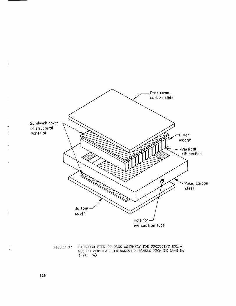
cover,
carbon steel
Sandwich
of structural
material Filler
wedge
rticalrib section
carbon
steel
Bottom
cover
Hole forevacuation tube
FIGURE 37. EXPLODEO VIEW OF PACK _SSEMBLY FOR PRODUCING ROLL-
WELDED VERTICAL-RIB SANDWICH PANELS FROM PH 14-8 Mo
(Ref. 74)
126
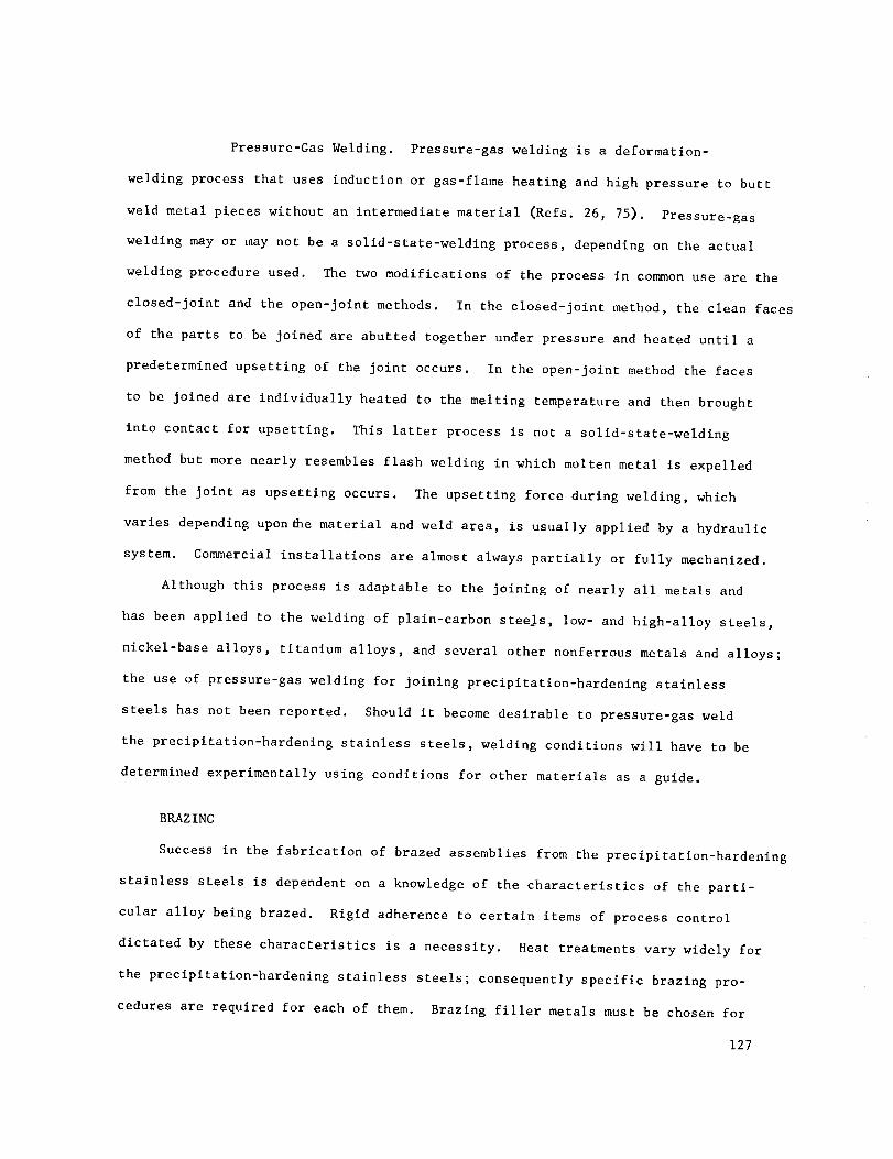
Pressure-GasWelding. Pressure-gaswelding is a deformation-
welding processthat uses induction or gas-flameheating and high pressure to butt
weld metal pieces without an intermediate material (Refs. 26, 75). Pressure-gas
welding mayor maynot be a solid-state-welding process, dependingon the actual
welding procedureused. Thetwomodifications of the process in commonuseare the
closed-joint and the open-joint methods. In the closed-joint method,the clean faces
of the parts to be joined are abutted together underpressureandheateduntil a
predeterminedupsetting of the joint occurs. In the open-joint methodthe faces
to be joined are individually heated to the melting temperatureand then brought
into contact for upsetting. This latter processis not a solid-state-welding
methodbut morenearly resemblesflash welding in which moltenmetal is expelled
from the joint as upsetting occurs. Theupsetting force during welding, which
varies dependingupon_e material andweld area, is usually applied by a hydraulic
system. Commercialinstallations are almost alwayspartially or fully mechanized.
Although this processis adaptableto the joining of nearly all metalsand
hasbeenapplied to the welding of plain-carbon stee_s, low- andhigh-alloy steels,
nickel-base alloys, titanium alloys, and several other nonferrousmetals and alloys;
the useof pressure-gaswelding for joining precipitation-hardening stainless
steels has not beenreported. Shouldit becomedesirable to pressure-gasweld
the precipitation-hardening stainless steels, welding conditions will haveto be
determinedexperimentally using conditions for other materials as a guide.
BRAZING
Successin the fabrication of brazedassembliesfrom the precipitation-hardening
stainless steels is dependenton a knowledgeof the characteristics of the parti-
cular alloy being brazed. Rigid adherenceto certain items of processcontrol
dictated by thesecharacteristics is a necessity. Heat treatmentsvary widely for
the precipitation-hardening stainless steels; consequentlyspecific brazing pro-
ceduresare required for eachof them. Brazing filler metals mustbe chosenfor
127

compatibility with the desired heat treatments in addition to the endusepro-
posedfor the brazement.
Thereare a large variety of brazing filler metalswhich can be usedto braze
the precipitation-hardening alloys. Selection of the proper filler metal for a
particular basemetal andapplication canbe a most critical operation. In most
cases the basemetal alloy is chosenfor its mechanicalproperties, resistance to
oxidation or corrosion, and to utilize the high strength-to-weight structures
possible with thesealloys. Consequently,a brazing filler metal mustmeetthe
requirementsimposedby the designer, be usable at temperaturesamenablewith the
thermal treatments necessaryfor the basemetal andmustrot adverselyaffect the
basemetal. Thelist of brazing filler metalswhich canbe usedon the stainless
steels is almost unlimited. Commercialfiller metals are available which contain
copper, gold, silver, palladium, nickel, manganese,iron, andmanyother elements
either as the baseor as additional elements. Usually they are groupedaccording
to their useful temperatureand oxidation resistance. Generalpurposesilver-base
brazing alloys are suitable for service up to about 800F, and the copper-manganese-
nickel alloys can be usedto aroundi000 F. For temperaturesabovei000 F the
nickel-base brazing alloys are most commonlyusedbut the alloys basedon either
gold or palladium are also widely used. Sometypical brazing filler metal alloys
for the precipitation-hardening stainless steels are listed in TablesXXIXandXXX.
Cleanliness of all parts to be brazedand of the filler metal is extremely
important to successful brazing. Anysurface contaminantwill inhibit wetting by
the molten brazing filler metal and should be removedprior to assembly. In the
caseof mostprecipitation-hardening stainless steels the presenceof aluminum/
and/or titanium also can inhibit brazing alloy flow. Theseelementsform refractory
oxides on the surface unless proceduresare usedwhich prevent their formation.
Theseproceduresmaybe copperor nickel plating the surface, or reducing the
oxides to metal, or depletion of the titanium and aluminumfrom the surfaces, or
brazing in a controlled atmosphereafter very careful cleaning followed by minimum
times before brazing.
128

TABLEXXIX. COMMONLY USED NOBLE METAL BRAZING ALLOYS FOR
PRECIPITATION-HARDENING STAINLESS STEELS
Ag
Composition, weight per cent
Au Pd Cu Li Zn Cd Other
Flow
lemperature,
F
AMS
Numbe_
_5 .... 15 -- 16 24 -- I145
50 ..... 15.5 -- 16.5 18 -- i175
56 .... 22 -- 17 -- 5 Sn 1205
50 .... 15.5 -- 15.5 16 3 Ni 1270
35 .... 26 -- 21 18 -- 1295
61.5 .... 24 ...... 14.5 In 1305
60 .... 30 ...... I0 Sn 1325
45 .... 30 -- 25 .... 1370
72 .... 27.8 0.20 ...... 1400
50 .... 34 -- 16 .... ].425
40 .... 30 -- 28 -- 2 Ni 1435
72 .... 28 ........ 1435
54 .... 40 -- 5 -- i Ni 1575
92.5 .... 7.3 0.20 ...... [635
54 -- 25 21 ........ 1742
63 .... 27 ...... 10 In 1346
75 -- 20 ........ 0.5 Mn 2050
-- 37.5 -- 62.5 ........ 1841
-- 82 .......... 18 Ni 1742
-- 80 -- 20 ........ 1666
-- 35 -- 62 ...... 3 Ni 1877
-- 50 25 ........ 25 Ni 2050
- 70 8 ........ 22 Ni 1899
- 35 -- 62 ...... 3 Ni 1886
-. 81.5 -- 16.5 ...... 2 Ni 1697
4769
4770B
4768
4272A
129

TABLEXXIX. (Continued)
Ag Au
Composition_ weight pe_ cent
Pd Cu Li Zn Cd
5
7.5
_4
75
6O
-- 20
-- 37
60 --
50 23.5
25 21
u_
DD
m--
Om
Other
3 In
40 Ni
Flow
Temperature,F
1643
1652
2260
1515
1728
AMS
Numbel
m.
130

TABLEXXX. COMMONLYUSEDNICKEL-BASEBRAZINGALLOYSFORPRECIPITATION-HARDENINGSTAINLESSSTEELS
Composition, weight per centCr Si B Fe Ni Other
BrazingTemperature AMSRange,F Number
L3.0-20.0 3.0-5.0 2.75-4.75 3.0-5.0 Balance l.OComax,0.6 Comax
6.n=8.0 3.0-5.0 2.5 -2.5
=- 3.0-5.0 1.8- 3.5
19 i0 --
13 ....
_-- 8 ----
•- 3.5 1.8
7 4.5 3.2
4 -- 0.9
3.5 2.5 0.9
-- 4.5 3.3
-- II.0 --
33 4 --
2.0-4.0 Balance 1.0Co max, 0.5 C max
-- Balance 1.0Co max, 0.5 C max
-- Balance ii P, O.IC
-- Balance 0.i C
-- Balance i0 P, 0.1C
-- Balance 17Mn, O.IC
-- Balance 0.06 C
3.0 Balance 6W, O.IC
-- Balance 45Mn, 0.1C
1.0 Balance 35Mn, 0.1C
-- Balance 20Co
30.0 Balance 3.5 P, 5.4Mo
-- Balance 25 Pd
1975-2200 4776
1850-2150 4777
1850-2150 4778
1700-_50 --
2100-2200 --
1700-1950 --
1900-2100 --
1950-2150 4779
1950-2150 --
2000-2150 --
1950-2050 --
1950 --
2150-2175 --
131

Mostbrazing methodssuchas torch, induction or furnace, canbe usedon
precipitation-hardening stainless steels. Methodswhich do notprotect the as-
semblyduring brazing require fluxes andposesubsequentflux removalproblems.
Theymayalso produceweakenedjoints due to entrapmentof flux residues. Conse-
quently, almost all brazing operations on these alloys are carried out in a
protective atmosphere. Dry, oxygen-freeatmospheresthat are usedinclude inert
gases, hydrogen,andvacuum. Atmosphereshavingdewpoints of -70 F or lower are
necessaryto prevent oxidation of the basemetal during heating. Carbonaceous
material should not be permitted in the brazing atmosphereor in the furnace.
Carbonin contact with the brazementand carbonaceousatmosphereswill carburize
the stainless steel. Carburization decreasesthe strength developedby later
hardeningtreatments (Ref. 14). Whenbrazing in inert atmospheresor vacuumthe
brazementshouldbe isolated from carbonaceousmaterials by the use of a thin
stainless steel "slip sheet". Slip sheets shouldbe discarded after eachuse.
Dissociated ammoniaatmospheresshouldnever be usedwith the precipitation-
hardeningstainless steels. Nitriding which results from the useof dissociated
ammoniawill lower the mechanicalproperties of these steels.
Additional details of brazing proceduresare determinedby the particular base
metal alloy, the brazing filler metal, and the intended service. Producersof the
materials being usedand the published literature shouldbe consulted for details
that maybe applicable to specific applications. Joint property data are not in-
cludedhere. Thepublished literature, standardhandbooksand manualscan be
consulted for this data.
Applications. The manufacture of honeycomb structural panels and hydraulic
systems for supersonic aircraft are significant applications of brazing to the
precipitation-hardening stainless steels.
Portions of these aircraft including parts of the wings and engine nacelles
are made from honeycomb structures to obtain maximum strength and minimum weight.
132

Oneof the basemetals usedfor these applications is 17-7 PH_another is
PH15-7 Mo. Brazing of these structures is accomplishedin a controlled atmos-
phereof argonwith the brazing filler metal andbrazing cycle chosento accomplish
heat treatment as part of the brazing cycle. Thetechniqueas applied to 17-7 PH
is thoroughly coveredin the BrazingManual(Ref. 76). A satisfactory combination
of brazing and heat treating cycle is outlined below:
(i) Braze1625-1750F for i0 minutesusing sterling silver plus lithium
brazing filler metal (93 per cent Ag-7 per cent Cuplus Li)
(2) Cool to I000 F within 30 minutes
(3) Cool to -I00 F and hold 8 hours
(4) Hardento specified condition (THI050or RH950)(Ref. 14).
A section of a retort and tooling usedto producestainless steel honeycombstruc-
tures is shownin Figure 38 (Ref. 77).
Theproduction of honeycombstructures from PH15-7 Moto give minimummechani-
cal properties of (UTS-225ksi, 0.2 per cent YS-200ksi and4 per cent elonga-
tion) canbe accomplishedwith the following brazing cycle for basematerials
having a nominal thickness of 0.020 inch.
(i) Brazeat 1640-1690F for I0 minutes
(2) Cool to I000F in 75minutes
(3) Transformat -I00 F for 8 hours
(4) Hardenat 900F for 8 hours (Ref. 14).
Other brazing cycles canalso be usedto meetmechanicalproperty requirements.
Brazing filler metals canalso be altered to meetparticular requirements. For
example,during the fabrication of contouredsandwichesfor the XB70aircraft,
indiumwasaddedto the basic silver-copper brazing alloy to reducethe thermal con-
ductivity, palladium to control the melting temperature, lithium to act as a flux
and promotewetting, andnickel powderto control flow in contouredareas (Ref. 78).
Figure 39 showsthe lay-up operation for XB70structures andFigure 40 indicates
the size andconfiguration of someof the panels.133

0
0
0
•_,1 ._1
(_'1,-..4 __M
_,_ °
_:: _ o
_._ _°_
4.1 ,-_
4J o_ 0
134

135
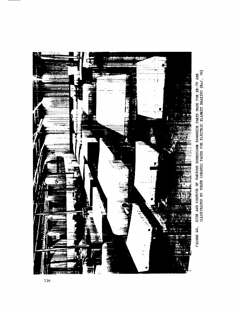
q_
v
rq
E-4
_o
OO
0_
_o
_B
136

Hydraulic systemsfor operation at 4000psi and450F are fabricated from
AM-350tubing andAM-355fittings which are brazed. Thebrazing alloy is the
eutectic silver-copper alloy plus lithium (71.8Ag-28Cu-0.2Li)whichmelts at about
1500F where it is not necessaryto heat treat for maximumproperties (Ref. 79). A
similar silver-base brazing filler metal whichmelts at 1710F is usedwhenheat
treatment is required. A valve with fittings which are to be brazedlater to
AM-350tubing is shownin Figure 41. Thebrazing filler metal is preplaced. Joints
in the tubing are madeby placing a portable induction-heating tool aroundthe joint
and fitting. Typical joint designsare shownin Figure 42 (Ref. 80). Inspection
holes on the chamferedportion of the fittings permit examinationof brazing
filler metal flow. Thejoint is protected by an inert atmosphereduring brazing.
This is shownschematically in Figure 43.
Thenickel brazing filler metalswhich contain boron are widely usedfor Join-
ing precipitatlon-hardening stainless steels. As is the casewhenusing these
filler metals on other basemetalscaution mustbe exercised to assure their
proper use. Theyhavea tendencyto dissolve the basemetal andpenetrate due to
diffusion. This is mostimportant whenbrazing thin sections. Properly made
Joints will be as strong as the parts Joinedandhighly oxidation andcorrosion
resistant. Someexamplesof assembliesmadefrom 17-7 PHwith a brazing filler metal
having the nominalcomposition82Ni-4.5Si-2.9B-7.0Cr-3Feare shownin Figures 44
and45 (Ref. 81).
JOINTQUALITY
Precipitation-hardening stainless steel weldmentsmaycontain undesirable
features that will interfere with proper operation in service. Inspection tech-
niques that will detect suchundesirable features mustbe used. For manyapplica-
tions it is desirable to determinethe causesof the undesirable features so proper
remedial and repair procedurescanbe initiated.137
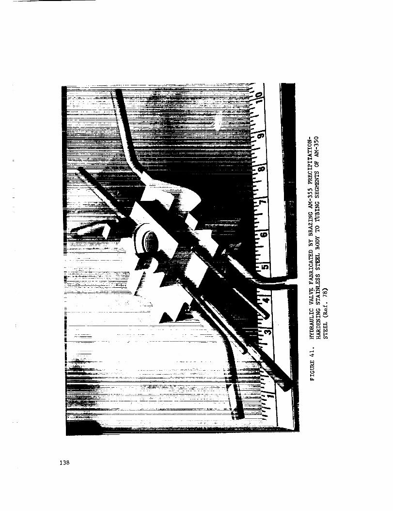
Z_O_
I-4
r_r_
z
Zi-4
_°
14-1
,4"
r_
138

,--4
0
G[-4 0
0
Z <
_-_ _J
0
p_ Z
0
I--4
139
A p-Pyrex plenumrgon / . ,
Work /cnomDer
! _coiJ /
r--_---P-F --F'i , , , nI I I_, iil I°I Ioi ,,, _/I _ I() _L,!_LI Io!_ ,,,, )
[,,':-,I "-"- _ _, ,',',i •"" _il_- _"' '_
Plenumchomber / "_ k___
closeout ond \ Tube
alignment fixture _Brozing sleeve
FIGURE 43.BRAZED JOINT FOR B-70 HYDRAULIC SYSTEM,ILLUSTRATING TOOLING USED DURING BRAZING(Ref. 78)
140

141

FIGURE 45. THESE TUBES ARE ABOUT 20 INCHES LONG
AND 8 INCHES IN DIAMETER WITH A WIRE
HELIX EXTENDING THE LENGTH OF THE TUBE.
Both tube and wire are made of 17-7 PH,
brazed with a nickel-base filler metal.
Part was hardened after brazing and
there was no evidence of cracking or em-
brittlement. (Ref. 81)
142

INSPECTION
Precipitation-hardening stainless steel weldmentsare inspectedusing
methodssimilar to thoseusedfor conventional stainless steel weldments. Non-
destructive inspections are almost alwaysperformedbut destructive inspection
generally is performedonly occasionally on completedproduct joints. It is
often necessaryand desirable to checkchangesin dimensionsthat mayhavere-
sulted fromwelding. Thevisual- andmeasurement-typeinspections performedfor
this purposemayalso include checksof weld-joint profile andmeasurementsof the
weld thickness. Various inspection proceduresalso are used to insure that the
joints producedare of satisfactory quality. Themostcommonlyusedtechniques
in this area include visual, dyepenetrant, andX-ray techniques. Various types
of leak tests are also usedon componentsdesignedto contain gasesor fluids.
DEFECTS
Thedefinition of joint defects is arbitrary. Manyyears of experience
havebeengained with welding codesand specifications that either prohibit or
allow certain features characterized as defects. Featuresrecognizedas defects
are generally limited in accordancewith conservativepractices. This approach
to defects has beenquite successful in the past, but is of someconcernwhen
dealing with manyof the newermaterials being used in various types of fabrication.
This concernis basedon the belief that the removalof certain types of features
classified as nonallowabledefects often results in moredamageto the service-
ability of a structure than the damagethat potentially might havebeendoneby
allowing the feature to remain. Thereluctance of manywelding engineersto repair
certain features is basedon this feeling, not on a desire to makethe welding jobeasier.
Thefabrication of defect-free welds is highly dependenton the quality
requirementsof applicable specifications and on the inspection methodsthat are
143

used. For example,hardly anywelding codeor specification allows cracks in a
weld. However,crackedwelds canand do get into service if inspection methods
that will insure detecting all cracks present in a weld are not required and
used.
Theonly reliable wayto determinewhatweld features are truly defects is
to evaluate the effects of such features in a test program. Suchan evaluation
mustinclude tests that are representative of the service conditions. Manyde-
fectlike weld features haveno effect on the static-tension properties of the weld.
However,these samefeatures maybe found to degradeperformanceseriously in a
fatigue test.
With the knowledgecurrently available about the performanceof fusion
weldments,a conservative engineeringapproachto defects shouldbe followed.
Typical arc-weld features that are sometimesclassified as defects are shownin
Figure 46.
Porosity. Data on porosity in precipitation-hardening stainless steels
is lacking. However, measures to control cleanliness and employment of good
welding techniques can reduce the occurrence of porosity. Some factors known
to cause porosity in welds include:
(I) Improper filler metals (4)
(2) Incorrect arc length (5)
(3) Low welding speed (6)
Insufficient sheet thickness
Air in shielding gas
Mosture.
DEFECTS IN RESISTANCE WELDS
Characteristics described as defects in resistance welds are difficult to
assess. Defects in resistance welds are generally subdivided into external and
internal defects. With the exception of cracks that are exposed to the exterior of
the sheets and that are obviously undesirable, the remaining external defects are
144

Mechanically blended ____¢/_ Notchafter welding
Concave underbend reinforcement /
(Suck back, suck up, etc.) /-_Underfill/weld concavity
Inclosions-- Crock_// C /_- Incomplete penetration
Overl°p_tYUndercut
Lock of fusion
__/-_-. Normal weld
Eccessive penetrationdrop-through
FIGURE 46. ARC-WELD DEFECTS
145

probably considered as such because they are indicative that the welding conditions
may not have been exactly right. External defects in this category are sheet
separation, surface pits, metal expulsion, tip pickup, and excessive indentation.
With internal defects, cracks are obviously undesirable, but there is very little
evidence that porosity in minor amounts is harmful to properties. The same is
true of either insufficient or excessive penetration. Typical defects in resistance
spot and seam welds and their causes are given in Figure 47 (Ref. 82).
Another feature that has been experienced with A-286 alloy is a phenomenon
known as "coring" or "incipient melting". This type of feature, shown in Figure 48,
may resemble small cracks in the plane of the sheet extending from the edge of
the weld nugget toward the unaffected base metal. These features are reported
to be regions along grain boundaries into which metal melted during welding had
flowed and subsequently solidified (Ref. 45). Central cracking in an A-286 spot
weld also is shown in Figure 48. Increases in electrode force and in weld time
reduce the likelihood of internal cracking (Ref. 83).
Work carried out on seam welding (Kef. 83) has shown that:
(i) One of the most common causes of internal cracks and porosity is
incorrect weld spacing. Where successive weld nuggets are too
close, cracks are often formed where they overlap.
(2) Slower welding speeds on longer weld and cool times can be used
to reduce cracking.
(3) Continuous-current seam welding eliminates cracking.
DISSIMILAR METALS
At times it becomes necessary to join the precipitation-hardening stainless
steels to alloys of similar metallurgical characteristics but different composi-
tions. It can also be desirable to joining these steels to other metals or alloys
which are entirely different in all respects. Welding and brazing are preferred
methods for making such dissimilar metal joints.
146

TYPICAL DEFECTS FOUND IN SEAM WELDING .AUSTENITIC STAINLESS STEELS AND
PREVALENT CAUSES
FOR THEIR OCCURRENCE IN ORDER OF THEIR IMPORTANCE
A--MATERIALS OF EQUAL THICKNESS
IDEAL __,,i,,_.i_,_ _ _ NUGGET
1. FNera_ice eMml_i.xn ,t II. Nurhee expalmio,. Ill. Exee_ivp iwdentatio,. IV. Void in nugget.i.t,,rhu.e. I. Electrode drew|ha t,_ 1, flee|rode dressing l_m I. ]nsul_cie.t electrode"
I h.,ulEei*'nt ehs.lrtxh' .harp. " sharp, force.f.re,., 2. I'Nee_udw. current fi)r 2. l.sulEei_.nt electrode 2. Exee._ive eurre.t or
2. E_,.,.,_ive purr,'.! tbr eleetr(.le fort'e, width. "on" time."-." time. 3. F(a'ei_n matter on _ur- :|, Exeea_iveelectrodef()ree. 3. Electrode dres._ing too
3. F'h.etnah, dr,_,_ing Im_ face. 4, Excessive eurrewt, flat.sharp. 4. 1.sufficie.t ¢(mlant n. 5. E_ee._ive "ran" time. 4. l,su_eient "off" time.
t. F',_r,.i_. matu'r at inter- rleetr_.|e_. 6, Iasu_ei_'nt coolant .. .5. Excessive rnn speed.face. electrodes.
_z ____
V. ('raek_ in nuuet. V. Cracksln .uF.get. V Cracks in nagger..s.. Hm'is,mtal rraek_ in B. Vertical cracks with C. In crack sensitive meta.
eenh,r, voi, l._. I, lnsuflieie.t electrodeI, I..ul_ele.t rice|rod,. I. Esee_ive current ,,r bree.
i'*_ree. "o1|'" time. 2. Electrode dre,_slng ton2, Insul_ieien; ",_" time. 2, l.mfliHe.t "off"' tin.., flat.3. F'leetr,_le dr,'_ina t_, 3. 1.sufllele.t electrode 3. ]asuflleient "o." time•
flat. force. 4. Exces._ive eurre.t.4. Esee_mvr eurrP.l. 4. EIc*trode dre_iwg t,m 5. lusuflicient "off" time•,_. Exert|re r_dl _IX'_L flat. (i. Excessive roll speed|.
%'1• ('racks in Imr,'nt nm,ta]. VII. Undersize ,m_et. VIIi. Esee_qive penetration. IX. I'.equal IN,re'|ration. X., I'id_alam'ed nuaget.I. |nsu_rWnt PlPvtr,._e 1. Insul_,.h,nt current, l. l'_xe_ive e_arrent. 1. t'n(Blual electrode dregs- l. Mi_|igBvne.t _,(
wPlth for nugget ,liam- 2. hisulE;.iem "-." time. 2. I';xees._iw, "mC tim,', ing. eh,etrod_'s.
,,Iv'r. :1. Ezee_iw,,'leetr,.h' force. 3. Electrode dressing t_a_ 2. ['m'_ ual electrical or '2. Off center dreg_iwg of'2. Ehs.tr,*|e dr,._._ing t,._ sharp, thernm e,m_luetivity of el_.tr_h.s.
sharp. 4. [ns_ffleie.t e_)lallt on electrodes.
3. Ew,.x_ive eurr,.n_ _r elevtr,_les. 3. l;Bl'qua[ distribution _ff",m'" tim*'. 5. ln._ut_cient electrical or e,a_lant on eh,etrode_.
4. ].sufSPi,.nt ",,R" time. thermal ('ondm'tivity ,ff5. Ew,'_ive r,)ll _l.'ed. eleetr_xh._.
X], (*oneilve !qial4_r4(If OIUl_l_et,I. Inixu_ic, ient ",m" time,_, hl_41l_('iellt ('uPrefit.3. ]li_u_rient width of
elet't rodeo.
Xll. _'u$._.I. |llSli_t'il'|it P(X)IiHIt Oil
_. Kxeea_ive current.3. insufl_eiewt t'h,etrode
f_wee.4. ]nh_U|fieiellt electrical ,_r
thermal conductivity ,ffeh,etr_h,s.
,5. ]':h_'trtaJe (]re._in_ too.har _.
(_, I(<_[i_ P,t_t _yt_ehroBhted(whell la)th r.lh :iredrivrw).
XII[. l_tek (ff t:mge.ey oroverlap.
_. Ese_,_.ive "off" time orr.II _l..e,I.
3. |B_tflit'iPt_t "t_B" time.
q47

B--MATERIALS OF UNEQUAl. THICKNESS
IDEAl. _x_._-,,_ _._,_,¢_ _,_ NUGGET
] l_¢k of penetration in thinsheet.
I. Electrt.h' dre.'_sh,g, h._fiat on thin sheet.
2. [':x ee_ive eh_'t r ode for ce.3. l';xee_ive electrical or
thermal conductivity ofeh'ctnMe ml thin sheet.
4, Insufficient ehwtrieal ortherm_l e_>mJucl'_yiJy .felectrode on heavy sheet.
11. Lack of penetration in Ill. Unbalanced nudeS. IV, Ezet'mive indentation.la_th sheets. I. Misalignment ofelec- I. Electrode d_ina t_m
1. Eh'ctrc_le dre_intz t(m tr(_le_, sharp at iod_ntatio_a,fl:tt. 2. ()_'-(.eltter ,lre_ing of 2. Ezeemiveelectrodeforee.
2. Exce_qiveeh'ctrt_i'ef,ree. electrode fares, 3, ExceSSive current or3, Insufficient current. "on" time.4. Insu_cient "off" time. 4. Insufficient width olelec-
trode at inden_tioo.
V. Excessive penetration. VI. Void in nugget. VII. ('racks in nugget. VII. C_'_eks in nuluttt.I. Electrode dre_ing too I. JnsuSeie_t electrode A. Horizontal cr,=cks at B. In crtu'k mitive m¢_l.
sharp on thin sheet, force, renter, I, ]mm[_ek.nt _ectmxk.2. Insu_cient electrode 2. Excessive current. I. lnsafficient electrode force.
force. 3. Excessive "on" time or force, 2. EloHrode dre_m[ too3. Excessive current or roll speed. 2. Insufficient "(dl" time. fiat.
"on" time. 4. Electrode dressing too 3. Electrode dipping too 3. lnm_eient"o_" time.4. Insufficient electrical or fiat. flat. 4, lnt_llicient "¢_" tim_.
thermal conductivity of 5. Insufficient "off" time. 4. Excessive enrrent orelectrode. "on" time.
,5. I_uffieient coolant.
VIII. Cr_cks in ptvent metal.I. Insufficient electrode
width for nugget diam-eter.
2. Electrode dreuing toosharp.
3. Excessive toll speed.4. Exee_ive current or
"on" time.,5. Imm_eient "off" time.6. Insufficient electrode
force.
FIGURE 47. (Continued)
148

FIGURE 48. INCIPIENT MELTING AND CENTRAL CRACKS IN
SPOT-WELDED A-286 ALLOY SHEETS
(Ref. 45)
149

The difficulties which may arise when joining dissimilar metals depend
mainly on the composition difference between the metals to be joined. If they
are similar as in the case of precipitation-hardenlng stainless steels to the
300-serles stainless steels the problems will not be great if good welding practice
is used. If they are widely different as in the case of joining precipitation-
hardening stainless steels to aluminum many problems may be encountered which
result from the formation of brittle phases. Most of these brittle phases exhi-
bit inferior mechanical properties. Welding of these joint systems usually results
in a technique which does not melt the stainless steel and the resultant joint is
essentially a braze weld. Such widely different alloys can also be joined by
brazing or diffusion welding when proper joint preparations are used. Joint
preparation often includes precoating one or both of the base metals or the in-
clusion of a third metal.
When GTA or GMA welding a precipitation-hardening stainless steel to other
similar alloys, for example, 17-7 PH to AM-350 or 17-7 PH to Ineonel X, the stan-
dard practice, including preparations and precautions, is the same as when welding
the alloy to itself. The major requirement is that a filler metal be used which
is compatible with both alloys and produces joints with adequate mechanical proper-
ties. Hastelloy W has been used widely as a filler metal for welding these dis-
similar combinations. It was developed for this purpose. Its composition
provides an ideal matrix when used to weld many different dissimilar hardenable
alloy combinations.
Electron-beam welding has been used to weld the precipitation-hardening
stainless steels to other alloys. This is done to take advantage of the minimum
effects of the weld on the base metals and also reduce costs. An example is the
turbine wheel shown in Figure 49. High-temperature resistant nickel-base turbine
blades are welded to a heat-treated A-286 disc. The mechanical properties of the
fabricated wheel components were not significantly affected. Electron-beam welding
150

• 11[1ii1 iiii iiiiiiiiiii ilrl rr _ r "
EB WELD
UDIMET 500RING OF BLADES
FIGURE 49. ELECTRON-BEAM-WELDED BIMETAL TURBINE WHEEL
(Ref. 84)
151

D, in.
.-6
.--s
-4
-3
\-\-2 \
-I
-0.50
AT, deg F
1800_
1600
/,\
")O'e#_'_ 1400
12OO'
I100--
I000-
900 _
0.25
(0.2 - a I )
A CD, in. (= 10-6in./in./F)
- 8 -'-"-o.o5o -7--0.040
-0.030 -6--oo2o - 5-
.... .._o.olo Index Line 2
-0.005 Solution to
sample problem -2-
-0.001
Sample problem:
Given: D= 2-1/2" -I
&T = 1180 F
(Cl2- O. i)= -3.0 x 10 -6
Solution:
&C =-O.O09in.
NOTES:
(I)
(2)
(3)
152
This homograph gives change in diameter caused by heating. Clearance
to promote brazing filler metal flow musl be provided o! brazing temp.
D = nominal diomeler of joint, inches
CD = change in clearance, inches
T = brazing temp minus room lemp, F
(21 = mean coefficient of thermal expansion, mole member, in./in./deg F"
(Z2= mean coefficient of thermal expansion, female member, in./in./deg F
This hOmograph assumes a case where al I exceeds a2, so that scale value
for ((2 Z -01 ) is negative. Resultant values for ACD ore therefore also negative,
signifying that the jointgop reduces upon healing. Where (G2-aEI) isposf-
live, values of ACDore read as positive, signifying enlargement of the joint
gap upon heating
FIO_RE 50. NOMOGRAPH FOR FINDING THE CHANGE IN DIAMETRALCLEARANCE IN JOINTS OF,,DISSIMILAR METALS FOR A
VARIETY OF BRAZINC SITUATIONS (Ref. 72)

can also be used to join the precipitation-hardening stainless steels to other
nickel-base alloys, martensitic stainless steels, and otheralloys. Ductility of
the joint will usually be equivalent to that of the least ductile joint component.
Brazing is perhaps the most satisfactory method for making Joints between the
precipitation-hardening stainless steels and other alloys. After proper considera-
tion is given to the heat treatments required, the proper choice of brazing filler
metal to suit these treatments and compatibility with both joint parts, the
techniques used are the same as for most metals. A very important factor to be
considered when brazing dissimilar metals is the difference in thermal expansion
between them. Joints must be designed so that the clearance between parts at
brazing temperature will promote capillary flow of the brazing alloy. The
homograph, Figure 50, will assist in calculating the proper clearances. The
coefficient of expansion of some metals and alloys of interest are given in
Table XXXI; data for other alloys can be found in standard handbooks. The useful
brazing filler metals were given in Tables XXIX and XXX.
Corrosion resistance should also be an important consideration when choosing
the design, material and brazing filler metal for dissimilar metal joints. The
subject is too complex for coverage in this report. Corrosion handbook data are
not always directly applicable to brazed assemblies due to the dissimilar metal
corrosion couples involved. Unless directly relative data are available, labora-
tory studies should be used to establish the feasibility of a particular joint
system in a particular corrosive environment.
In general, technology which is applicable to the brazing of the Type 300-
series stainless steels to unlike metals is applicable to similar joints in the
precipitation-hardening stainless steels. There must always be an awareness to
the effects of the brazing thermal treatments on the properties of the precipitation-
hardening alloy, however.
153

TABLE XXXI. COEFFICIENT OF THERMAL EXPANSION OF SOME COMMON ALLOYS
Coefficient of Expansion
Alloy (32-212 F) 10 -6 in/in/F
Type 302 stainless steel, annealed and cold rolled
Type 304L stainless steel, annealed
Type 321 stainless steel, annealed and cold rolled
Type 410 stainless steel, annealed and heat treated
AM-350, solution treated and hardened
15-7 Mo, Condition TH 1050
17-7 PH, Condition TH 1050
A-286, solution treated, quenched and aged
AISI 4340 steel, annealed
AISI 1020 steel, annealed
Ren& 41
Inconel, annealed
Inconel X, annealed
Nickel
Aluminum
Tungsten, sintered
Molybdenum, i/_% Ti, stress relieved
Tantalum, annealed
Columbium, annealed
Titanium, commercially pure
8.0
8.0
8.3
5.1
6.8
6.1
6.1
9.4
6.3
6.5
7.5
6.4
7.6
7.2
13.1
2.2
3.4
3.6
4.0
4.7
154

CONCLUSIONSANDRECOMMENDATIONS
Theprecipitation-hardening stainless steels canbe weldedby mostwelding
processes. With proper attention to heat treatment, filler metal choice, welding
technique, cleanliness, etc., high-quality high-strength joints can be readily
producedin mostalloys.
Fusionwelding of the precipitatlon-hardening stainless steels results in a
weld metal andheat-affected-zone mlcrostructure containing stable austenite.
Researchanddevelopmentstudies are neededwhichwill showbest howto control
the formation of stable austenite. In this wayweldswith properties morenearly
approximatingthose of the basemetal could be obtained without resorting to complete
postweldheat treatments.
It is also difficult to developfull strengths in the weld metal becausethe
microsegregationencounteredis difficult to homogenize.Researchis neededon the
influence of welding conditions on microsegregationin precipitation-hardening
stainless steel weld metals.
Precipitation-hardening stainless steels are divided in three different
classes or types: martensitic (Stainless W, 17-4 PH, 15-5 PH), Semiaustenltic
(17-7 PH, PH15-7 1,4o,AM-350,AM-355),andAustenitic (A-286, 17-10P,HNM). In
general, the welding of these alloys becomesincreasingly difficult as the alloy
content increases. ThePHsteels (lower alloy) steels present fewer problemsthan
the austenitic xteels suchas A-286. A-286will tolerate few variations from the
established procedures.
MARTENSITICPRECIPITATION-HARDENINGSTAINLESSSTEELS
In general these steels have excellent weldability. Theyare not crack sensi-
tive on cooling becauseof the low carboncontent, nor are they susceptible to the
hot cracking as associatedwith other copper-bearingstainless steels. Whenweld-
ing castings, attention mustbe paid the compositionbecausehot cracking maybe
155

encountered. This cracking has beenattributed to microheterogenity in the casting
structure. The17-4 PHsteel casting alloy should contain only 3 percent copper
as comparedto 4 percent copper for wroughtproducts. Hot cracking due to carbon
maybe encounteredwhenwelding the martensitic steels to carbonor low-alloy
steels. Recommendedwelding techniquesfor these joints are thosewhichminimize
dilution of the weld metal.
Preheating andpostweldheat treatments are not essential. Preheatingis
beneficial whenwelding heavysections or whenjoints are madeunderrestraint.
Somemartensitic alloys do not possessgreat ductility or toughness. Conse-
quently the foremostprecaution necessarywhendesigning, makingandusing welded
joints is to avoid notcheswhich mayinitiate cracking.
Since responseto heat treatment is very dependenton the alloy composition,
serious attention mustbe paid filler metal choice, joint fitup, joint cleanliness,
andother techniquevariables which maycausecompositionchanges. It should also
be mentionedthat compositionvariations within specification limits mayalso af-
fect the heat-treatment schedulesused. Closeliaison with the steel producer
is recommendedto develop the proper heat-treatment variations to produceweldments
of maximumutility.
Thereare no recommendationsfor researchon the martensitic precipitation-
hardeningstainless steels which are not coveredby the general areas coveredabove.
SEMIAUSTENITICPRECIPITATION-HARDENINGSTAINLESSSTEELS
Muchof whathas beensaid of the techniquesand recommendedwelding practices
for the martensitic type steels is also applicable to the semiaustenitic type.
The17-7 PHalloy is the mostcommonof the semiaustenitic types. It is
mostoften weldedin sheet metal thicknessesand in this form requires no unusual
welding procedures. Preheatingand posting are not required. Filler metals are
available to meetmostfinal strength needs. Whenwelding without the use of a
filler metal, problemsmaybe encounteredin meetingductility and toughnessre-
156

qu_rements. Nitrogen is recommendedas a shielding gasadditive to overcomehot-
cracking and ductility problemson single-pass welds. Porosity can result if
nitrogen is usedon multipass welds.
Aluminum-bearingalloys require techniquedevelopmentto overcomesurface films
on the surface of the weld pool. With proper techniquesthese films do not hurt
weld properties or prevent goodwelds. Theuse of alternating welding currents
and an inert-gas shield of eitherhelium or a hellum-argonmixture is recommended.
Careful control of voltage current, gas flow, and especially travel speedcan
also minimize the formation of surface films.
Whenresistance welding 17-7 PHsheet materials, material preparation (clean-
ing ) shouldbe carefully controlled. Poorly cleanedsurfaces causeexcessivemetal
expulsion, porosity, and electrode sticking. Thebest properties are obtained when
resistance welds are madejust before or after the final hardening treatment.
ThePH15-7 Moalloy requires moreattention to welding proceduresthan other
semiaustenitic alloys. If ductile welds are required at high strength levels very
precise control of filler metal compositionsandwelding operations are a necessity.
Special helium-nitrogen gas mixtures are necessaryto properly weld PH15-7 Mo
without filler metal addition.
Thegeneral recommendationsmadeat the beginning of this section are applicable
to the semiaustenitic precipltation-hardening stainless steels.
AUSTENITICPRECIPITATION-HARDENINGSTAINLESSSTEELS
It has beenindicated that the austenitic alloys are the mostdifficult of
the precipitation-hardening classes to weld. A-286is the most commonof these.
In thin sections and in the absenceof restraint, it is not difficult to weld.
A-286 in heavygagesis classed as a difficult-to-weld alloy. Troubles begin at
thicknessesbelow0.25 inch. Hot cracking is the result of a loss of ductility,
due to eutectic melting at the grain boundaries, in the temperaturerange 1150-
1350F. Lowheat inputs andminimumrestraint on cooling are recommendedto
157

minimize cracking. Weldcracking whenencounteredmaybe stoppedusing a differ-
ent filler metal. Heat-affected-zonecracking has beenthe subject of muchresearch
andmoreis recommended.A basic study of the causesof heat-affected-zone cracking
in heavygageA-286steel is recommended.Themost fruitful area for research on
this subject wouldbe in a basic study of the mechanismof heat-affected-zone crack-
ing.
There is also a needfor continued developmentof filler metals for alloys such
as A-286which morenearly equal the compositionof the basemetal anddo not cause
cracking.
Weldingproceduresand limitations which are recommendedfor the austenitic
precipitation-hardening alloy A-286are:
(i) Weldin the solution-treated condition. Donot weld or repair weld
the hardenedalloy.
(2) Weldcarefully cleanedjoints only. Cleanbetweenpasses.
(3) Usemultipass weldsand high travel speedswhenwelding heavygages.
(4) Avoid all restraint if possible.
(5) Usebutt weldswhereverpossible, metal-to-metal fitup andcareful
alignment.
(6) Useinert-gas arc welding with automatic voltage control.
Other austenitic alloys, 17-10PandHNM,are evenmoredifficult to weld. Under-
beadcracking due to the high phosphoruscontent is almost impossible to overcome.
Researchis neededto developgoodweldability in these alloys whichhave a combin-
ation of properties for certain specific applications. Themicrosegegrationproblem
is acute in these alloys and shouldbe included as part of any future researchas
recommendedpreviously. Theywere developedfor usewheregoodstrength and low
magneticpermeability are required.
158

APPENDIX A
WELDING PROCESSES
159

WELDINGPROCESSES
Weldingprocessesthat havebeenusedfor joining precipitation-hardenlng
stainless steels are describedbriefly in the following. Theseprocessesare
described in considerable additional detail in the published literature (Refs.
26, 85).
SHIELDEDMETALARC
Shieldedmetal-arc welding is usually donemanually. Theheat required to
melt the filler metal and joint edgesis producedby an arc betweena covered
electrode and the work. Theelectrode is composedof a metal rod coatedwith
materials which whenheatedby the arc produce(i) a gaswhich shields the arc
area from the atmosphere,(2) promoteselectrical conductionacross the arc,
(3) producesslags which refine the molten pool, provide someprotection from
the atmosphere,andaddalloying elements, and (4) provide materials for control-
ling beadshape. Figure A-I is a sketch which showsthe basic operation of this
process.
GASTUNGSTEN-ARCWELDING
In this process,which maybe usedmanuallyor with automatic equipment,the
heat to melt both filler metal and joint edgesis producedby an arc betweena
tungsten (nonconsumable)electrode on the work. A shield of protective gassur-
roundsthe arc andweld region. Filler metal mayor maynot be addedto the weld.
If it is, it is not normally a part of the arc circuit andis called a "cold wire"
addition. Theprocessi_ often called the GTAor TIGprocess.
Argon, helium, or a mixture of the two gasesare usedfor shielding against
the atmosphere. Thesegasesare chemically inert, they do not react with other
materials. Argonis moreextensively used than helium.
Figure A-2 is a sketch of a gas tungsten-arc system.
160

Electrode coating __'_
Core_ir_ ///fJShielding_ "_,_
atmosphere _ l,J
Arc pool_ _'_.----_,_- .-,_W' ^.Solidified S/og-_ __,-_,__Arc stream
_{_C rater depth
Base metal
FIGURE A-I. SKETCH OF SHIELD-METAL-ARC WELDING OPERATION
(Ref. 26)
161
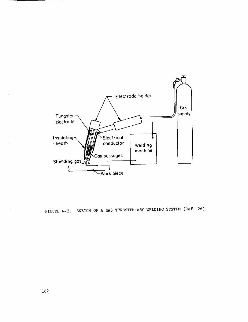
Electrode holder
Tungsten--\ _/_
electrode _
Insuloting--,_tYlIE"E'e_Yt_.°_!sheoth _/_ conductor Welding
!/111 machine
_;/_'_ Gos possoges _Shielding gas ,{,_ [
_" _--Wo_ piece
IGas I
_upply I
FIGURE A-2. SKETCH OF A GAS TUNGSTEN-ARC WELDING SYSTEM (Ref. 26)
162

GAS METAL-ARC WELDING
In this process, it is used both manually and with automatic equipment; the
heat to melt filler metal and the joint edges is produced by an arc between a metal
wire (consumable) electrode and the work. Arc and weld are shielded from the at-
mosphere by a shield of protective gas. The electrode is a small-diameter wire
(about 0.035 to 0.065 in diameter for stainless steel) with no coating. The
process is often called the GMA or MIG process.
Argon, helium, argon-helium mixtures, and argon-oxygen mixtures are all used
for shielding gases. Argon with 1 or 2% oxygen is generally used with stainless
steels. Figure A-3 is a sketch of a gas metal-arc welding system.
SUBMERGED ARC WELDING
The heat to melt the filler metal and joint edges is obtained from an arc
between a base-metal electrode or electrodes and the work. The arc and weld zone
is shielded by a blanket of flux which covers the joint and the end of the electrode.
The arc is buried beneath the flux. The flux is a granular mineral material whose
composition and properties are designed to:
(i) Provide protection from the air during welding.
(2) Provide materials to deoxidize and alloy the weld metal.
(3) Provide (when melted) a conductive path for the welding current.
(4) Provide a slag which molds the surface of the weld.
Generally, an amount of flux about equal to the weight of filler wire is melted
during the welding operation. It is this melted portion of the flux which
accomplishes most of the actions listed above. The unmelted portion of the flux
is picked up by vacuum cleaning equipment and recirculated to the weld head.
Figure A-4 is a sketch which shows the details of this process.
PLASMA-ARC WELDING
This process melts the filler metal and joint edges by using the heat produced
by passing a gas through an arc and an orifice to produce high-temperature plasma.
163

Wire drive moy be locotedin welding 9un hondle orot wire reel
Shielding gas
c welder
Contoctor
W ire
, ilControls for
governing wiredrive, current,gos flow, ondcooling woter,if used
II
II
Gos I_upply I
I
FIGURE A-3. SKETCH OF A GAS METAL-ARC WELDING SYSTEM (Ref. 85)
164

To automatic wire feed
ing wire
¥ AC or DCFlux feed
Flux Granulated fluxidified flux
retaining Fused flux
FinishedVee groove weld surface
Malta Base metal
weld metal Weld metal
Weldbacking -T-AC or DC
FIGURE A-4. SKETCH OF SUBMERGED-ARC WELDING OPERATION(Ref. 26)
165

Welding is done using a "transferred" arc which means that the work has to be part
of the welding electrical circuit. This process is a specialized adaption of the
gas tungsten-arc process. In welding, inert gases are usually used to form the
plasma. An additional inert gas shield is used to protect arc, plasma, and weld
from the air. The advantages of the process over gas tungsten-arc welding are:
(I) Higher energy concentration
(2) Improved arc stability
(3) Higher energy transfer.
Using certain gas flow and electrical power settings the arc plasma torch
can be turned into an effective cutting tool. Plasma cutting is particularly
effective with stainless steels since it does not depend on oxidation to facili-
tate cutting. Figure A-5 is a sketch of a plasma-arc welding system.
ELECTRON-BEAMWELDING
This is a fusion-welding process which does not use an arc as a heat source.
The work is bombarded by a high-energy, high-density stream of electrons. Prac-
tically all of the elctron energy is transformed into heat when the electrons
impact the work. As originally developed, electron-beam welding was done in an
evacuated chamber. In about 1963, some capability for welding at pressures up to
atmospheric was developed. While this loses the advantage of the high-purity atmos-
phere which the vacuum represents, it increases the adaptability of the process.
One outstanding feature of electron-beam welds is the very narrow welds
(high depth-to-width ratio) that can be made with the process. It is possible to
produce welds only 1/16 inch wide in steel plate I/2-inch-thick plate. Equipment
of two types is available. One type uses accelerating voltages below 60,000
volts and the other uses accelerating voltages above 60,000 volts. The two types
have characteristics which make them useful for a wide variety of work. In most
electron-beam welders, the work is not a part of the electrical circuit, although
it must be grounded.
166

12 volts I250 amp
-Argon25 cfh
Plosmo
orgon3cfh
hielding
orgon30 cfh
o. Comporison Gos-Tungsten Arc ond Plosmo Torch
Welding
power
supply
m
High-
frequency
generotorm
ic IR i
I Electrode
rifice gos
Shielding
gos
Outer
shieldingring
FIGURE A-5. SKETCH OF PLASMA-ARC TORCH AND SYSTEM
(Ref. 85)
167

Electron-beam welders are in effect X-ray tubes and produce X-radiation.
must be taken to assure that personnel is shielded from this radiation.
Figure A-6 shows sketches of two electron-beam welding systems.
Care
RESISTANCE SPOT, SEAM, AND PROJECTION WELDING
The heat required for fusion in these processes is obtained by the resistance
of the parts being welded to a relatively short time flow of high-density electric
current. The current is introduced into the parts by electrodes of one type or
another. Force is applied through the electrodes to maintain contact between the
parts to assure a continuous electric circuit and to forge the heated parts together.
Normally a small amount of metal is melted at the faylng surfaces of the Joint. It
is the coalescence of this melted metal which creates the weld. Spot welding is
diagrammed in the sketch in Figure A-7.
A wide variety of equipment is used for resistance welding. Different types
of current are used, although about 90% of con_nercial installations are 60-cycle
alternating current.
The three types of welds are characterized by the following:
(i) Spot welds are individual welds whose shape and size is determined
by the electrodes. A series of spot welds is usually used to make
a joint.
(2) Seam welds are a series of overlapping spot welds made with circular
rotating electrodes.
(3) Projection welds are spot welds whose location is determined by
projections formed into the parts to be welded.
Sketches showing the basic characteristics of the three types of welding are shown
in the sketch in Figure A-8.
FLASH WELDING
Flash welding is a butt welding process in which the entire area of the sur-
faces to be welded are heated by a flow of electrical current across the joint.
168

E
0
E
E
U0
c0
z
"0
E:3
0>
03
I-,4
_._
0
,d
H
169

Electrode
Workpiece
Workpiece
Force
-Current flo,w
Force
Elect rode
FIGURE A-7. SKETCH SHOWING ELECTRICAL FLOW AND HEAT GENERATION
IN A SPOT WELD
170

Electrodes or Electrodes or Electrodes or Projection
After
welding
Spot Weld Seom Weld Projection Weld
FIGURE A-8. SKETCHES SHOWING CHARACTERISTICS OF SPOT,SEAM, AND PROJECTION WELDING (Ref. 26)
171

The flow of current produces a flashing action which is the fusing of contacting
points of metal on the surfaces being welded. Flashing plus resistance heating
melts the faying surfaces. When the proper temperature is reached, force is
applied to upset the parts together. The upset squeezes out the molten metal and
produces a solid-state weld. Flash welding is actually a solid-state welding proc-
ess, although molten metal is involved in preparing the faying surfaces for welding.
Figure A-9 is a sketch which shows the basic characteristics of the process.
BRAZING
Brazing is a process in which a filler metal having a melting point below
that of the base metal is used to make a joint. The process is called brazing
when temperatures above 800 F are required to make the joint. It is called
soldering when temperatures below 800 F are used. Brazed joints normally have
large areas and very small thickness. Fluxes may be used to clean and protect the
joint area during heating. When fluxes are not used, rigorous precleaning and
high-purity atmospheres are required to produce good joints. The filler metal
is melted in contact with the joint area. Capillary forces cause the metal to
flow into the joint. Because capillary forces are important in determining the
extent and quality of the Joint, it is necessary to provide and maintain proper
clearances in the joint during the joining operation. Clearances of 0,002 inch
to 0.005 inch are common, Smaller or larger clearances may prevent flow of the
filler metal into the joint. With larger clearances, even preplaeed filler
metals may flow out of the joint when they melt,
SOLID-STATE WELDING
Solid-state welding includes any process where two or more pieces of metal
are metallurgically joined without the formation of a liquid phase. A metallurgi-
cal Joint is one in which the weld is the result of the action of atomic forces
rather than mechanical interlocking. All solid-state welding operations require
forces which press faying surfaces into contact with each other. These forces
172

f Flo,h1
FIGURE A-9. SKETCH SHOWING BASIC CHARACTERISTICS OF
FLASH-WELDING PROCESS (Ref. 26)
173

may or may not be high enough to cause gross upset. Solid-state welding is dis-
cussed in detail in Reference 66. Solid-state welding includes a number of
processes, but they can be divided into two classes:
(i) Diffusion welding
(2) Deformation welding
Diffusion Welding. In this type of solid-state welding, diffusion across
the joint interface is primarily responsible for forming the weld. Only a small
amount of deformation occurs during the process. Diffusion welding is done at
elevated temperatures. This makes it easier to obtain the mlcroplastic flow required
to produce intimate contact of the faylng surfaces and decreases the time required
to obtain the amount of diffusion and grain growth required to complete the joint.
Dissimilar metals may or may not be used in the joint to increase diffusion rates.
Deformation Welding. Deformation welding includes those processes in
which gross plastic flow is the major factor in weld formation, Diffusion is not
normally required for weld formation, although it may contribute if welding is
done at elevated temperatures. The bonding mechanism with this process is not
known precisely. It is generally believed that gross deformation breaks up the
surface films which prevent intimate contact at the faying surfaces, forces
clean surfaces intocontact, and perhaps provides the energy needed to complete
weld formation. Deformation welds are produced at temperatures from room tempera-
ture (cold welding of aluminum and copper) to temperatures Just below the melting
point (upset-butt welding of steel).
174

REFERENCES
1.
2,
3.
4.
5.
6,
7,
8.
9.
I0.
II.
12.
13.
14.
Search of Journals for Literature on Welding of Precipitation-
Hardening Stainless Steels, Battelle Memorial Institute, Columbus,
Ohio, Memorandum from C. A. Butler to J. J. Vagi (July 18, 1966)
Bibliography on Joining of Stainless Steels, Redstone Scientific
Information Center, Redstone Arsenal, Huntsville, Alabama, Problem
No. 14SSJO (May 18, 1966).
Bibliography on Joining of Stainless Steels, Redstone Scientific
Information Center, Redstone Arsenal, Huntsville, Alabama,
Bibliography No. STEL, Problem No. 0.5 (May II, 1966)
"Welding of Stainless Steels", a Report Bibliography, DDC Search
Control No. 051576, Defense Documentation Center for Scientific
and Technical Information, Cameron Station, Alexandria, Virginia
(May 31, 1966).
"Stainless Steel", NASA Literature Search No. 2554, 1962 to June 2,
1966, National Aeronautics and Space Administration, Scientific and
Technical Information Facility, College Park, Maryland (June 2,
1966). 329 Citations.
Linnert, G. E., "Welding Precipitation-Hardening Stainless Steels",
Welding Journal, 36 (1), 9-27 (January, 1956).
Harkins, F. G., "Welding of Age-Hardenable Stainless Steels",
Welding Research Council Bulletin No. 103, American Welding Society,
New York, New York (February, 1965).
Ludwigson, D. C., and Hall, A. M., "The Physical Metallurgy of
Precipitation Hardenable Stainless Steel", DMIC III (April 20, 1959).
Armco 15-5 PH Precipitation Hardening Stainless Steel Product Data,
Armco Steel Corporation (September, 1965).
Armco 414 Ti Stainless Steel Product Data, Armco Steel Corporation
(1965).
Personal Communication, R. Kaltenhauser, Allegheny Ludlum Steel
Corporation (June 23, 1966).
"Almar 362, A Mar-Aging Stainless Steel", Technical Horizons,
Allegheny Steel Corporation (1966).
Roberts, D. A., Roach, D. B., and Hall, A. M., "Physical and Mechanical
Properties of Nine Commercial Precipitation-Hardenable Stainless Steels",
DMIC 112 (May, 1959).
Personal Communication, Harry Espy, Armco Steel Corporation, Baltimore,
Maryland (June, 1966).
175

I
15. Armco 17-4 PH Stainless Steel, Armco Steel Corporation (November, 1964).
16. Welding Armco 17-4 PH Stainless Steels -- Fabricating Data Bulletin,
Armco Steel Corporation (February, 1966).
17. Welding Armco Stainless Steels, Armco Steel Corporation (July, 1963).
18. Espy, R. Harry, "Welding the Newer Grades...PH Alloys and Manganese
Stainless Steels", Metal Progress (August, 1964).
19. Metals Handbook, Volume 2 -- Heat Treating, Cleaning, and Finishing,
American Society for Metals (1964).
20. Personal Communications with J. Browning and C. Hazard, Thermal
Dynamics Corporation, Lebanon, New Hampshire (July 22, 1966).
21. Personal Communication with E. Malcolm, Industrial Stainless Steel
Corporation, Cambridge, Massachusetts (July 22, 1966).
22. Personal Communication with D. Wolf, Mills-Wolf Company, Bedford,
Ohio (July 22, 1966).
23. Personal Communication with A. L. Schoeni, Ling-Temco-Vought, Inc.,
_ugust I, 1966).
24. "Electron-Beam Metalworking", Hamilton-Standard Division, United
Aircraft Corporation, Windsor Locks, Connecticut, Report H 63-368.
25. Roach_ D. B., and Hall, A. M., "The Engineering Properties of
Hardenable Stainless Steels", Battelle Memorial Institute, Titanium
Metallurgical Laboratory, Report No. TML 48 (July 20, 1956).
26. Welding Handbook, Fifth Edition, Section 2, Welding Processes,
American Welding Society (1963).
27. Kaltenhauser, R., "Covered Electrode and Submerged Arc Welding of
AM-355", Allegheny Ludlum Steel Corporation, Research Center,
Brackenridge, Pennsylvania, Report No. SS-442 (February 13, 1961).
28. Personal Communication with Arthur L. Schoeni, Ling-Temco-Vought,
Inc. (August I, 1966).
29. "Weldability of PH 15-7 Mo Alloy", The Boeing Company, Seattle,
Washington, Report No. MRR2-624-1 (July 13, 1959).
30. "Preliminary Investigation of the Weldability of AM-350 Steel",
The Boeing Company, Seattle, Washington, Report No. MRR2-624 (April 8,
1959).
31.
176
"Tungsten Inert-Gas-Shielded-Arc Welding of High-Strength Steel,
Part V", Republic Aviation Corporation, Farmingdale, New York,
Final Report, Report No. MRP 58-73, Contract No. AF 33(600)-38042,
(November 30, 1959).

32. Meredith, H. L., "Fusion Weldingof Railed Skin Panels for B-70Triple Sonic Plane", WeldingJournal, 41 (9) 822-831 (1962).
33. Russel, B., and Butler, H., "Thin-Skin Welding", Electric Welding,
Linde Company, _ (4), 1-3 (1962).
34. "Out-of-Position TIG Machine Welding", Chance-Vought Corp., Division
of Ling-Temco-Vought, Inc., Oallas, Texas, Final Report, Report
No. 2-22300/3R-3, (April 15, 1963).
35. Lewis, R. E., "Fracture Toughness as Influenced by Phase Transforma-
tions in Manual Welds in AM-350 Steel Sheet", Lockheed Missiles and
Space Company, Research Laboratories, Palo Alto, California, Final
Report, Report No. 2-60-64-13 (April, 1964).
36. Lewis, R. E., "Fracture Toughness of Inert Gas Shielded Non-
Consumable Electrode Automatic Welds in AM-350 Steel Sheet", Lockheed
Missiles and Space Company, Research Laboratory, Palo Alto, California,
Final Report, Report No. 2-60-64-18 (July, 1964).
37. Lewis, R. E., "Fracture Toughness of Repair Welds in AM-350 Steel
Sheet", Lockheed Missiles and Space Company, Research Laboratories,
Palo Alto, California, Final Report, Report No. 2-60-64-19 (July,
1964).
38. McElrath, T., "Short-Arc Consumable-Electrode Welding Applications
and New Developments", Welding Journal, 39 (I0), 1044-1050 (1960).
39. Personal Con_nunication with R. L. O'Brien, Linde Company, Newark,
New Jersey (July 19, 1966).
40. Filipski, S. P., "Plasma Arc Welding", Welding Journal, 43 (ll),
937-943 (1964).
41. Personal Contact with Hamilton-Standard Division, United Aircraft
Corporation (July 13, 1966).
42. Personal Contact with Sciaky Brothers Corporation (April 19, 1966).
43. Anderson, G. V., "Electron-Beam Welding at North American Aviation",
Proceedings of the Fourth Symposium on Electron-Beam Technology,
Alloyd Electronics Corporation, Cambridge, Massachusetts (1962)
44. "Electron Beam Tames Production in Portable Welding Chamber",
Iron Age, 191 (18_ (May 2, 1963).
45. Squires, I. F., "Determination of Resistance Spot-Welding Charac-
teristics for Some Heat-Resisting Stainless Steels", British
Welding Journal, _ (3), 149-157 (March, 1962).
46. "Welding: Aluminum, Magnesium, Non-Hardening Steels or Alloys, and
Titanium, Spot, Seam and Stitch", Military Specification MIL-W-6858B.
177

47. Mishler, H. W., Monroe,R. E., and Rieppel, P. J., 'Welding of High-
Strength Steels for Aircraft and Missile Applications", Defense
Metals Information Center, Battelle Memorial Institute, Columbus,
Ohio, DMIC Report I18 (October 12, 1959).
48. Beeson, P. A., Summary Report on "Resistance Welding of 17-7 PH,
AM-350, and PH 15-7 Mo Precipitation-Hardening Stainless Steel
Alloys", North American Aviation, Inc., Special Report NA-57-770
(June 23, 1957).
49. "AM-350/AM-355 Precipitation-Hardening Stainless Steels'_ Allegheny
Ludlum Steel Corporation Brochure (1963).
50. "Foil-Gage Steel Rocket Chambers Spot Welded", Welding Engineer,
44 (12), 40, 42 (December, 1959).
51. Kaltenhauser, R. H., "Welding Maraging Stainless Steels", Welding
Journal, 44 (9), 394s-397s (September, 1965).
52. "Armco Precipitation-Hardening Stainless Steels, Welding Armco
17-7 PH Stainless Steel, Armco Fabricating Data Bulletin, Armco
Steel Corporation, Middletown, Ohio (April l, 1960).
53. "Armco Precipitation-Hardening Stainless Steels, Welding Armco PH
15-7 Mo Stainless Steel", Armco Fabricating Data Bulletin, Armco
Steel Corporation, Middletown, Ohio (April 20, 1959)
54. "Resistance Welding A-286", Boeing Airplane Company, Wichita,
Kansas, Report W-2, Contract AF 33(600)-34670 (September 28, 1959).
55. "RW: Well Adapted to Joining Stainless", Welding Engineer,
39-41 (August, 1963).
56. Draft of Final Report, "Welding Characteristics, Exhibit 'D'",
Contract No. AF 33(657)-11461, Boeing-North American, "A Joint
Venture", Los Angeles, California, Report No. BNJV-D-F (June 30,
1964).
57. Henderson, D. C., "Spot Welding Characteristics of PH 15-7 Mo
Stainless Steel"d Convair, A Division of General Dynamics
Corporation, Fort Worth, Texas, Process Control Test Report No. 4595
(March 27, 1961).
58. "Cleaning and Pickling Procedure for A-286 Stainless Steel",
Boeing Airplane Company, Wichita, Kansas, Report F-2, Contract
No. AF 33 (600) -35992 (January 27, 1959).
Funk, E, J., and Willis, A. C., "An Investigation of Lap Seam Welds
in 17-7 PH Stainless Steel", Welding Journal, 37 (9), 897-905
(September, 1958).
59.
178

60. Rice, L. C., "Pressure-Tight Close-OutJoint by ResistanceWelding",BoeingAirplane Company,Seattle, Washington,ManufacturingResearchReportNo. 2-72-08 "B" (December22, 1959).
61. "Rings for Exacting Requirements",AmericanWeldingandManufacturingCompany,Warren,Ohio.
62. "ProcessingandMaterials Reviewfor Aircraft DesignManual",ReportNo. ARDL-TR-56-7,Part I, A. O. Smith Corporation, AeronauticalDivision, Milwaukee,Wisconsin,Contract No. AF18(600)-1513(Datenot reported).
63. "Aircraft Products", King Fifth WheelCompany,Mountaintop,Pennsylvania(Brochure).
64. PersonalCommunicationfrom R. C. Singleton, GregoryIndustries, Inc.,Lorain, Ohio (July 18, 1966).
65. Keith, R. E., Wdowiarz,J. W., Vagi, J. J., Monroe,R. E., andMartin, D. C., "Final Report onManufacturingMethodsfor High-FrequencyResistanceWelding", AdvancedFabricating TechniquesBranch,ManufacturingTechnologyDivision, Wright-Patterson Air Force Base,Ohio, Report AMFL-TR-65-9,Contract AF33(657)-11262(December,1964).
66. Hauser,D., Kammer,P. A., andMartin, D. C., "Fundamentalsof Solid-State WeldingandTheir Application to Beryllium, Aluminum,andStainless Steel", RedstoneScientific Information CenterReport -RSIC437 (July 15, 1965).
67. Winslow,P. M., andMclntyre, D. V., "Study of Adhesionand Cohesion
in Vacuum", Hughes Aircraft Company, Culver City, California, Final
Report, NASA Contract NAS 8-11066 (August 20, 1965) (ASME Publication
65-MET-16) (ASM Technical Report D5-18.4).
68. Maropis, N., "Development of Ultrasonic Welding Equipment for
Refractory Metals", Aeroprojects, Inc., West Chester, Pennsylvania,
Contract AF 33(600)-43026, ASD Project No. 7-888, Second Interim
Report (December, 1961), Tenth Interim Report (August, 1965).
69. Garrett, B. R., Blank, G. F., and Ranadive, A. J., "Broad Applications
of Diffusion Bonding", Hexcel Products, Inc., Berkeley, California,
Contractor Report No. CR-409, Contract No. NAS7-273 (March, 1966).
70. Feduska, W., and Horigan, W. L., "Diffusion Bonding High-Temperature
Alloys With Beryllium", Welding Journal, 41 (I) 28s-35s (January, 1962).
71. Leach, J. E., Jr., "Diffusion Bonding of Structures by Hot Rolling
Plate Mill Techniques", Douglas Missile and Space Systems Division,
Santa Monica, California, Paper No. 3207 presented at SAE National
Aeronautic and Space Engineering and Manufacturing Meeting,
Los Angeles, California (October 5-9, 1964).
179

72. "Roll-WeldedStructures", DouglasAircraft Company,Inc., BattelleMemorialInstitute, Columbus,Ohio (November,1963).
73. Bianchi, L. M., "Fabricating Underan Inert Atmosphere",Metal Progress,87 (3), 127-131(March,1965).
74. VanOrsdel, J. R., Bartlett, E. S., Grube,K. R., andOgden,H. R.,"Developmentof Practice for CompositeRolling of Structural MetalPanels", Battelle MemorialInstitute, Columbus,Ohio, U. S. ArmyMaterials ResearchAgency,Watertown,Massachusetts02172,SecondQuarterly Report, AMRA-CR-66-02/2,Contract DA-19-066-AMC-308(x)(July, 1966).
75. Lage, A. P., "PressureVessel Fabrication", Paperpresentedat SAEAerospaceManufacturingForum,Los Angeles,California (October5,1964).
76. Brazing Ma.nual , American Welding Society, New York, New York (1963).
77. Kugler, A. N.,"Brazing Honeycomb Structures", Air Reduction Sales Co.,
New York (no date).
78. Reinsch, W. A. '_etals and Fabrication Methods for the B-70"
Metal Progress, 79 (3), 70-78 (March, 1961).
79. "Brazed Joints, Thin-Wall Tubing Streamline B-70 Plumbing", Space/
Aeronautics, 3 (5) 75 (May, 1960).
80. Brock, C. G., "Portable Induction Brazing Makes Better Hydraulic
Joints", Welding Design and Fabrication, 34 (7), 32-34 (July, 1961).
81. Cape, A. T., "Brazing Alloys for Guided Missiles", Metal Progress,
74 (3), 99-104 (September, 1958).
82. "Seam Welding Defects in Austen_tic Stainless", Engineering Data
Sheet No. 281, Welding Engineer (January, 1964).
83. Knowlson, P. M., "An Explanation of Factors Affecting the Formation
of Internal Cracks in Spot Welds in Nimonic Alloys and Some Stainless
Steels", British Welding Journal, _ (3), 168-170 (March, 1962).
84. Meier, J. W., "Production Applications of Electron-Beam Welding",
Paper No. 63-WA-122, Preprint paper Annual Meeting ASME, Philadelphia,
Pennsylvania (November, 1963).
85. Welding Handbook, Fifth Edition, Section 3, Welding, Cutting and
Related Processes, American Welding Society (1964).
180

APPROVAL
WELDING OF PRECIPITATION-HARDENING
STAINLESS STEELS
By J. J. Vagi, R. M. Evans, and D. C. Martin
The information in this report has been reviewed for security
classification. Review of any information concerning Department of
Defense or Atomic Energy Commission programs has been made by the
MSFC Security Classification Officer. This report, in its entirety,has been determined to be unclassified.
This document has also been reviewed and approved for technical
accuracy.
l
W. A. WILSON
Chief, Methods Development Branch
_vision
Director, Manufacturing Engineering
Laboratory
181