r electric actuator operation and … series 74 electric actuator operation and maintenance manual 1...
TRANSCRIPT
TheHighPerformanceCompany
R
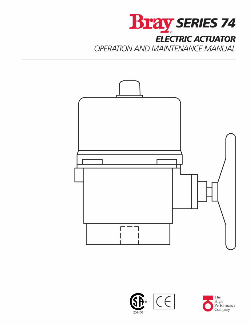
SERIES 74ELECTRIC ACTUATOR
OPERATION AND MAINTENANCE MANUAL
204450

BRAY Series 74 Electric ActuatorOperation and Maintenance Manual
1
TABLE OF CONTENTS PAGE
SPECIFICATION ---------------------------------------------------------------------------------- 2TRAVEL CAM & LIMIT SWITCHES ADJUSTMENT ------------------------------------------------- 3MECHANICAL STOPS ---------------------------------------------------------------------------- 4POTENTIOMETER -------------------------------------------------------------------------------- 4MODULATING CONTROL BOARD ----------------------------------------------------------------- 5TROUBLE SHOOTING ---------------------------------------------------------------------------- 6LUBRICATION, NOTICE & STORAGE ------------------------------------------------------------ 6PARTS FOR S74 –0890 & 1330 -------------------------------------------------------------- 7,8PARTS FOR S74 –2210 & 3100 ------------------------------------------------------------- 9,10WIRING DIAGRAM FOR 110V/220V AC 1-PH / ON/OFF ------------------------------------ 11WIRING DIAGRAM FOR 110V/220V AC 1-PH / MODULATING ------------------------------ 12WIRING DIAGRAM FOR 110V/220V AC 1-PH / MODULATING
LOCAL/REMOTE SELECTION SWITCH ----------------------------------------------------- 13WIRING DIAGRAM FOR 110V/220V AC 1-PH / ON/OFF
LOCAL/REMOTE SELECTION SWITCH ----------------------------------------------------- 14WIRING DIAGRAM FOR 110V/220V AC 1-PH / 4-20MA OUTPUT SIGNAL ------------------ 15WIRING DIAGRAM FOR 110V/220V
SAME SWITCH PARALLEL WIRING -------------------------------------------------------- 16WIRING DIAGRAM FOR 220V/380V/440V 3-PH /WITH REV. STARTER / ON/OFF ----------- 17WIRING DIAGRAM FOR 220V/380V/440V 3-PH /WITH REV. STARTER / MODULATING ----- 18WIRING DIAGRAM FOR 220V/380V/440V 3-PH /WITH REV. STARTER
4-20MA OUTPUT / ON/OFF -------------------------------------------------------------- 19WIRING DIAGRAM FOR 220V/380V/440V 3-PH / 4-20MA
OUTPUT SIGNAL (NO STARTER) ---------------------------------------------------------- 20WIRING DIAGRAM FOR 24V DC ON/OFF ----------------------------------------------------- 21WIRING DIAGRAM FOR 24V AC ON/OFF ----------------------------------------------------- 22WIRING DIAGRAM FOR 220V/380V/440V 3-PH ON/OFF ----------------------------------- 23WIRING DIAGRAM FOR 24V DC / MODULATING ---------------------------------------------- 24WIRING DIAGRAM FOR 24V AC / MODULATING ---------------------------------------------- 25
FOR INFORMATION ON THIS PRODUCT AND OTHER BRAY PRODUCTS
PLEASE VISIT US AT OUR WEBPAGE - www.bray.com
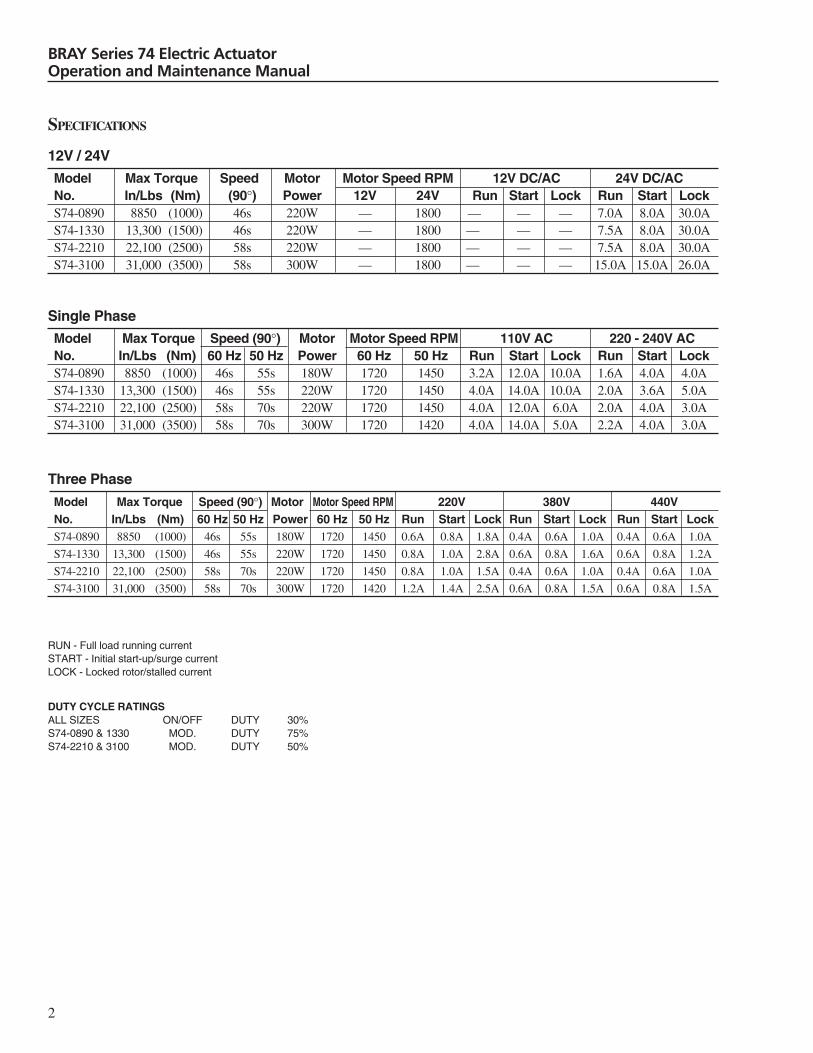
Model Max Torque Speed (90°) Motor Motor Speed RPM 220V 380V 440VNo. In/Lbs (Nm) 60 Hz 50 Hz Power 60 Hz 50 Hz Run Start Lock Run Start Lock Run Start LockS74-0890 8850 (1000) 46s 55s 180W 1720 1450 0.6A 0.8A 1.8A 0.4A 0.6A 1.0A 0.4A 0.6A 1.0A
S74-1330 13,300 (1500) 46s 55s 220W 1720 1450 0.8A 1.0A 2.8A 0.6A 0.8A 1.6A 0.6A 0.8A 1.2A
S74-2210 22,100 (2500) 58s 70s 220W 1720 1450 0.8A 1.0A 1.5A 0.4A 0.6A 1.0A 0.4A 0.6A 1.0A
S74-3100 31,000 (3500) 58s 70s 300W 1720 1420 1.2A 1.4A 2.5A 0.6A 0.8A 1.5A 0.6A 0.8A 1.5A
Three Phase
BRAY Series 74 Electric ActuatorOperation and Maintenance Manual
2
SPECIFICATIONS
Model Max Torque Speed Motor Motor Speed RPM 12V DC/AC 24V DC/ACNo. In/Lbs (Nm) (90°) Power 12V 24V Run Start Lock Run Start LockS74-0890 8850 (1000) 46s 220W — 1800 — — — 7.0A 8.0A 30.0AS74-1330 13,300 (1500) 46s 220W — 1800 — — — 7.5A 8.0A 30.0AS74-2210 22,100 (2500) 58s 220W — 1800 — — — 7.5A 8.0A 30.0AS74-3100 31,000 (3500) 58s 300W — 1800 — — — 15.0A 15.0A 26.0A
12V / 24V
RUN - Full load running currentSTART - Initial start-up/surge currentLOCK - Locked rotor/stalled current
Model Max Torque Speed (90°) Motor Motor Speed RPM 110V AC 220 - 240V ACNo. In/Lbs (Nm) 60 Hz 50 Hz Power 60 Hz 50 Hz Run Start Lock Run Start LockS74-0890 8850 (1000) 46s 55s 180W 1720 1450 3.2A 12.0A 10.0A 1.6A 4.0A 4.0AS74-1330 13,300 (1500) 46s 55s 220W 1720 1450 4.0A 14.0A 10.0A 2.0A 3.6A 5.0AS74-2210 22,100 (2500) 58s 70s 220W 1720 1450 4.0A 12.0A 6.0A 2.0A 4.0A 3.0AS74-3100 31,000 (3500) 58s 70s 300W 1720 1420 4.0A 14.0A 5.0A 2.2A 4.0A 3.0A
Single Phase
DUTY CYCLE RATINGSALL SIZES ON/OFF DUTY 30%S74-0890 & 1330 MOD. DUTY 75%S74-2210 & 3100 MOD. DUTY 50%

BRAY Series 74 Electric ActuatorOperation and Maintenance Manual
3
LS4 - Aux. switch cam factory set at full closed position.Can be set at an intermediate position if required.
LS3 - Aux. switch cam factory set at full open position.Can be set at an intermediate position if required.
LS2 - Close travel switch cam.Rotate cam clockwise to decrease closedposition and vice versa.
LS1 - Open travel switch cam.Rotate cam clockwise to increase full openposition and vice versa.
LS4
LS3
LS2
LS1
LS4
LS3
LS2LS1
TORQUE CAM ADJUSTMENT (FACTORY SET)S74-0890 & 1330
TS1 - Counter-clockwise: Lowers torque value trip setting.Clockwise: Increases torque value trip setting.
TS2
TS1 TS1 - Counter-clockwise: Lowers torque value trip setting.Clockwise: Increases torque value trip setting.
TORQUE CAM ADJUSTMENT (FACTORY SET)S74-2210 & 3100
TS1 - Counter-clockwise: Increases torque value trip setting.Clockwise: Lowers torque value trip setting.
TS1 - Counter-clockwise: Increases torque value trip setting.Clockwise: Lowers torque value trip setting.
TS2
TS1
TRAVEL CAM & LIMIT SWITCH ADJUSTMENT(ALL SIZES)LS1 & LS2 - Open and Close travel switch cams can beset to users preferred Open & Close valve positions.The motor is powered via the travel switches normallyopen (N.O.) contacts the cam depresses the switch lever
ClosedDirection
OpenDirection
ClosedDirection
OpenDirection
to allow motor to run. Adjusting cam so that switch leveris not depressed will stop motor.LS3 & LS4 - Are voltage free aux. travel indication switchcams and can be set at any position between 0 and 90degrees to provide remote position indication. Travelcams can be adjusted with a 2.5mm hex key.

4
BRAY Series 74 Electric ActuatorOperation and Maintenance Manual
MECHANICAL STOPS
FOR ELECTRIC OPERATION:Please refer to “Travel Cam & Limit Switch Adjustment”The motor should be stopped by the end of travel limitswitches (LS1 & 2) being activated by their respectivecams.
FOR MANUAL OPERATION:1) Slacken the locknuts & back-out the socket head
travel stop bolts.2) Adjust open (LS1) & close (LS2) travel limit switch
cams to desired end of travel positions.3) Using handwheel drive actuator to it’s fully open
position (confirm that open travel position switch isactivated). Turn handwheel one half turn openingactuator more. With hex key, screw open travel boltin until it comes to a stop against internal stop pad.
4) Secure bolt by tightening locknut against housing.5) Repeat steps 1 to 4 for close travel bolt.
POTENTIOMETER
Potentiometers turn with transmission shafts, and canprovide a feedback signal for position indication.
Potentiometer terminals 1, 2, 3 are wired to terminalblocks 5, 6, 7.
When a valve is closed: 5,6 — 1K Ohm6,7 — 0K Ohm
When a valve is opened: 5,6 — 0K Ohm6,7 — 1K Ohm
For modulating controllers, potentiometer terminals 1, 2,3 are wired to terminal blocks 8, 9, 10.
When a valve is closed: 8,9 — 5K Ohm9,10 — 0K Ohm
When a valve is opened: 8,9 — 0K Ohm9,10 — 5K Ohm
CLOSE
OPEN
5
BRAY Series 74 Electric ActuatorOperation and Maintenance Manual
MODULATING CONTROL BOARD: INTERFACE
ATerminal Block
Green Lamp (Open Indicator)
Red Lamp (Closed Indicator)
Sensitivity Switch is set in position 3 at factory.
Pos. 1 being most sensitivePos. 0 being least sensitive(Closed angle trim pot)
Output
B
1
2
3
4
5
67
8
VR2
9
10
11
12
Input
PowerNL
0
1 2 3
45
678
9(Open angle trim pot)
Standard factory setting is #1,4,& 8 ON #2,3,5,6 &7 OFF.
8 7 6 5 4 3 2 1
ON
Yellow Lamp(Power Light)
* S1 ~ S8 D.I.P. Switch
VR1
Input Signal4~20mA1~5V DC2~10V DC
Output Signal4~20mA2~10V DC
Comparison Part
Control Part Driving Part
Control Object AC Motor
Control VolumeValve 90°
270° VR(5K Ohm)
FeedbackSignal
* D.I.P. SWITCH SETTINGS (WARNING: Disconnect powersupply prior to changing settings)
S1,2 Select Input Signal:4-20mA, 1-ON, 2-OFF1-5VDC, 1-OFF, 2-OFF2-10VDC, 1-OFF, 2-ON
S3,4,5 Select Output Signal:2-10VDC, 3-ON, 4-OFF. 5-ON4-20mA, 3-OFF, 4-ON, 5-OFF
S6 Valve fully closed on 4mA or 1V or 2V InputSignal and full open on 20mA or 5V or 10VInput Signal, 6-OFF (for reverse operationswitch 6-ON)
S7,8 Position on loss of incoming control signal:Valve will fully close – 7-ON, 8-OFFValve will fully open – 7-OFF, 8-ONValve will stop where it is – 7-ON, 8-ONIf reverse operation (4mA to open, 20mAto close) reverse 7 & 8 positions.
VR TRIM POT ADJUSTMENT
VR2 (Close Travel) Turn fully clockwise, provideclose signal, then turn pot. counter clockwise 3 to 6turns until red light stays on.
VR1 (Open Travel) Turn fully counter clockwise,provide open signal, then turn pot. clockwise 3 to 6turns until green light stays on.

6
BRAY Series 74 Electric ActuatorOperation and Maintenance Manual
Problem Possible cause Solutions
Motor does not operate Check supply power and voltage are correct. Check by meter.Any blisters on the capacitor? If so replace.Is the gear train locked-up? Remove motor to check.
Motor stops running Is power supply short circuited? Check wiring.Any foreign objects in pipeline? Check for obstructions.
Unable to fully open/close Loose/Misaligned cam? Adjust/Tighten using wrench.Bent valve stem? Replace valve stem.Mechanical stop adjustment incorrect? Check position of stops.
Valve stops operating when motor Gear worn out? Replace gear.is running. Sleeve adapter worn out or broken? Replace sleeve adapter.
Broken valve stem or actuator Replace valve stem or actuatortransmission shaft. transmission shaft?
Abnormal control for operating two or Controlling circuit connected in Refer to the wiring diagram.more actuators simultaneously. tandem or parallel?
Motor overheats. Incorrect voltage? Check by meter.Valve torque too high? Replace with larger actuator.High working frequency? Check duty cycle.Is motor stem or bearing binding? Replace the binding parts.
Occasional on/off actuator failure. Simultaneous input power on/off. Check if the selection switch isnormal.
Vibration when valve is closed. Motor brake spring fatigued or Replace spring or Teflon.Teflon worn?
ACTUATOR TROUBLESHOOTING CHART
LUBRICATIONThe gearbox of the Bray actuator is enclosed, and it hasalready been lubricated sufficiently with high tempera-ture lubricant at the factory sufficient for use for up to twoyears.
IMPORTANT NOTICES & MAINTENANCE
Notices:1. Make sure the voltage is correct before power-up.2. Turn power off before conducting any mainte-
nance.3. Seal the casing and conduit entrance after wiring
to prevent dust or water contamination.4. The angle of electric actuator installation must
between 0~180 degree. Do not install upsidedown or below the horizontal.
5. Do not install when hazardous or explosive gasesmay be present.
6. The frequency of open and close operation isrestricted to every 5 minutes. Avoid too high acycle frequency.
7. When more than one electric actuator needs tooperate simultaneously, please connect withindividual cables & not in parallel.
8. Connect the ground wire to PE inside the electricactuator.
9. The warranty period of our product is one year.
Storage:1. The actuator should be placed in a clean and dry
place, and protected from the weather andextreme vibration.
2. If actuator needs be stored outside, it must beprotected from excess moisture, dust, andweather.
7
BRAY Series 74 Electric ActuatorOperation and Maintenance Manual
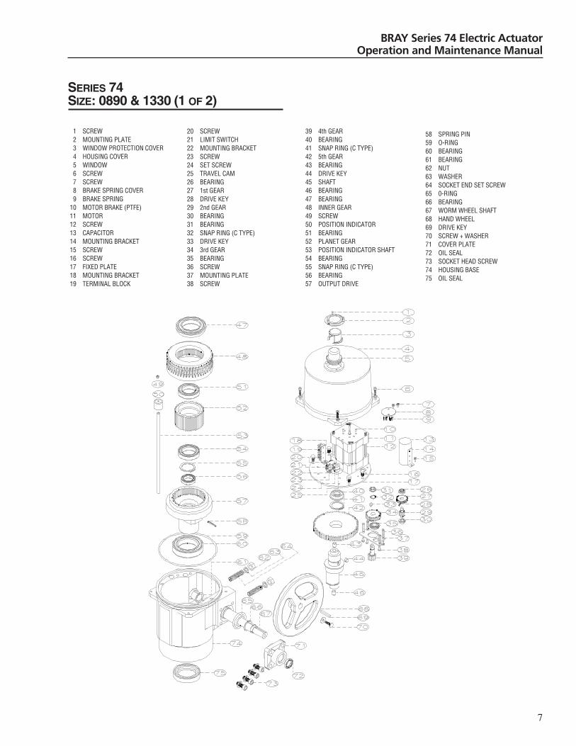
SERIES 74SIZE: 0890 & 1330 (1 OF 2)
1 SCREW2 MOUNTING PLATE3 WINDOW PROTECTION COVER4 HOUSING COVER5 WINDOW6 SCREW7 SCREW8 BRAKE SPRING COVER9 BRAKE SPRING
10 MOTOR BRAKE (PTFE)11 MOTOR12 SCREW13 CAPACITOR14 MOUNTING BRACKET15 SCREW16 SCREW17 FIXED PLATE18 MOUNTING BRACKET19 TERMINAL BLOCK
20 SCREW21 LIMIT SWITCH22 MOUNTING BRACKET23 SCREW24 SET SCREW25 TRAVEL CAM26 BEARING27 1st GEAR28 DRIVE KEY29 2nd GEAR30 BEARING31 BEARING32 SNAP RING (C TYPE)33 DRIVE KEY34 3rd GEAR35 BEARING36 SCREW37 MOUNTING PLATE38 SCREW
39 4th GEAR40 BEARING41 SNAP RING (C TYPE)42 5th GEAR43 BEARING44 DRIVE KEY45 SHAFT46 BEARING47 BEARING48 INNER GEAR49 SCREW50 POSITION INDICATOR51 BEARING52 PLANET GEAR53 POSITION INDICATOR SHAFT54 BEARING55 SNAP RING (C TYPE)56 BEARING57 OUTPUT DRIVE
58 SPRING PIN59 O-RING60 BEARING61 BEARING62 NUT63 WASHER64 SOCKET END SET SCREW65 0-RING66 BEARING67 WORM WHEEL SHAFT68 HAND WHEEL69 DRIVE KEY70 SCREW + WASHER71 COVER PLATE72 OIL SEAL73 SOCKET HEAD SCREW74 HOUSING BASE75 OIL SEAL
BRAY Series 74 Electric ActuatorOperation and Maintenance Manual
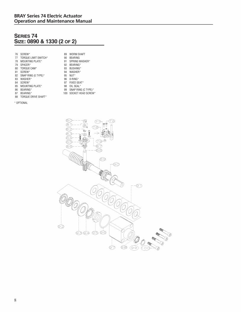
SERIES 74SIZE: 0890 & 1330 (2 OF 2)
76 SCREW*77 TORQUE LIMIT SWITCH*78 MOUNTING PLATE*79 SPACER*80 TORQUE CAM*81 SCREW*82 SNAP RING (E TYPE)*83 WASHER*84 SCREW*85 MOUNTING PLATE*86 BEARING*87 BEARING*88 TORQUE DRIVE SHAFT*
* OPTIONAL
89 WORM SHAFT90 BEARING91 SPRING WASHER*92 BEARING*93 BUSHING*94 WASHER*95 NUT*96 0-RING*97 FIXED SEAT*98 OIL SEAL*99 SNAP RING (C TYPE)*
100 SOCKET HEAD SCREW*
8
BRAY Series 74 Electric ActuatorOperation and Maintenance Manual
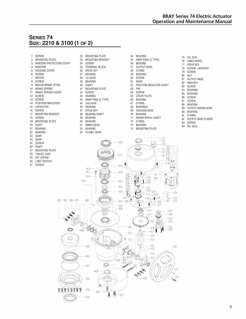
SERIES 74SIZE: 2210 & 3100 (1 OF 2)
1 SCREW2 MOUNTING PLATE3 WINDOW PROTECTION COVER4 WINDOW5 HOUSING COVER6 SCREW7 MOTOR8 SCREW9 MOTOR BRAKE (PTFE)
10 BRAKE SPRING11 BRAKE SPRING COVER12 SCREW13 SCREW14 POSITION INDICATOR15 CAPACITOR16 SCREW17 MOUNTING BRACKET18 SCREW19 MOUNTING PLATE20 SHAFT21 BEARING22 BEARING23 GEAR24 GEAR25 SCREW26 SHAFT27 MOUNTING PLATE28 TRAVEL CAM29 SET SCREW30 LIMIT SWITCH31 SCREW
32 MOUNTING PLATE33 MOUNTING BRACKET34 SCREW35 TERMINAL BLOCK36 DRIVE KEY37 BEARING38 1st GEAR39 BEARING40 SHAFT41 MOUNTING PLATE42 SCREW43 BEARING44 SNAP RING (C TYPE)45 2nd GEAR46 BEARING47 DRIVE KEY48 BEARING SHAFT49 BEARING50 BEARING51 INNER GEAR52 BEARING53 PLANET GEAR
54 BEARING55 SNAP RING (C TYPE)56 BEARING57 OUTPUT GEAR58 O-RING59 BEARING60 SCREW61 GEAR62 POSITION INDICATOR SHAFT63 PIN64 SCREW65 COVER PLATE66 BEARING67 O-RING68 BEARINGS69 HOUSING BASE70 BEARING71 WORM WHEEL SHAFT72 O-RING73 BEARING74 MOUNTING PLATE
75 OIL SEAL76 HAND WHEEL77 DRIVE KEY78 SCREW + WASHER79 SCREW80 NUT81 OUTPUT BASE82 WASHER83 SCREW84 BEARING85 BUSHING86 SCREW87 SCREW88 BEARING89 OUTPUT WORM GEAR90 BEARING91 O-RING92 OUTPUT BASE FLANGE93 SCREW94 OIL SEAL
9

10
BRAY Series 74 Electric ActuatorOperation and Maintenance Manual
SERIES 74SIZE: 2210 & 3100 (2 OF 2)
95 SCREW*96 TORQUE LIMIT SWITCH*97 MOUNTING PLATE*98 SPACER*99 TORQUE CAM*
100 SET SCREW*101 SNAP RING (E TYPE)*102 WASHER*103 SCREW*104 MOUNTING PLATE*105 BEARING*106 BEARING*107 TORQUE DRIVE SHAFT*108 SPRING*109 BEARING*
* OPTIONAL
110 BUSHING*111 O-RING*112 MOUNTING PLATE*113 SCREW114 O-RING115 WASHER116 WASHER117 OIL SEAL*118 WORM WHEEL119 COVER PLATE120 BUSHING121 BEARING122 SPRING123 SCREW*
11
BRAY Series 74 Electric ActuatorOperation and Maintenance Manual
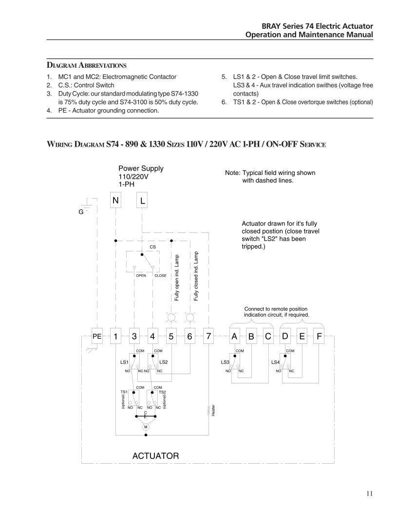
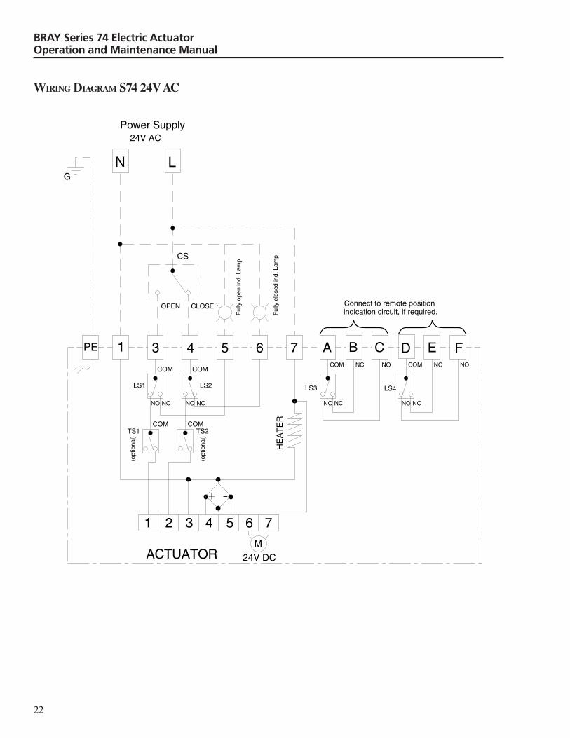
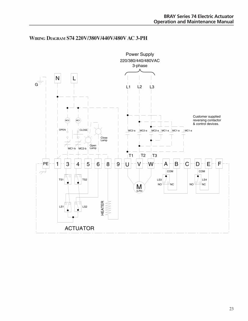
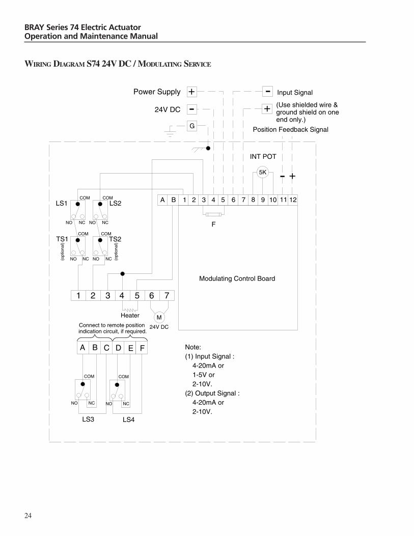
DIAGRAM ABBREVIATIONS
1. MC1 and MC2: Electromagnetic Contactor2. C.S.: Control Switch3. Duty Cycle: our standard modulating type S74-1330
is 75% duty cycle and S74-3100 is 50% duty cycle.4. PE - Actuator grounding connection.
5. LS1 & 2 - Open & Close travel limit switches.LS3 & 4 - Aux travel indication swithes (voltage freecontacts)
6. TS1 & 2 - Open & Close overtorque switches (optional)
WIRING DIAGRAM S74 - 890 & 1330 SIZES 110V / 220V AC 1-PH / ON-OFF SERVICE
1 3 4 5 6 7 A B C D E F
N L
Power Supply110/220V1-PH
LS1 LS2
ACTUATOR
CS
Note: Typical field wiring shown with dashed lines.
PE
TS1 TS2
LS3 LS4
NC
COM
OPEN CLOSE
COM
NO
NC
COM
NO NC
COM
NO
NCNO
COM
NCNO
COM
NCNO
M
C Hea
ter
Ful
ly c
lose
d in
d. L
amp
Ful
ly o
pen
ind.
Lam
p
G
(opt
iona
l)
(opt
iona
l)
Actuator drawn for it's fully closed postion (close travel switch "LS2" has been tripped.)
Connect to remote position indication circuit, if required.

12
BRAY Series 74 Electric ActuatorOperation and Maintenance Manual
WIRING DIAGRAM S74 - 890 & 1330 SIZES 110V / 220V AC 1-PH / MODULATING SERVICE
1 2 3 4 5 6 7 8 9 10 11 12
N
L
+
-
5K
A B C D E
Modulating Control Board
110/220V AC
LS4LS3
Note:(1) Input Signal : 4-20mA or 1-5V or 2-10V.(2) Output Signal : 4-20mA or 2-10V.
LS2LS1
TS2TS1
F
4321
M
90/180 DC
F
BA
Position Feedback Signal
- +
INT POT
NO NC
COM
NO NC
COM
NO NCNO NC
COM
NO NC
COM
NO NC
COM
COM
Connect to remote position indication circuit if required.
Heater
Input Signal
(Use shielded wire & ground shield on one end only.)
Power Supply
(opt
iona
l)
(opt
iona
l)

13
BRAY Series 74 Electric ActuatorOperation and Maintenance Manual
WIRING DIAGRAM S74 110V / 220V AC 1-PH / MODULATING SERVICELOCAL / REMOTE SELECTOR SWITCH
5K
Modulating Control Board
TS1
Pot.
LS1 LS2
7
N
L
6
54
Heater
Switch (1)Switch (2)
Remote
LocalClose
Open
G R OLamp(open)
Lamp(close)
Lamp(power)
_
A
D
C
B
F
E
12111098
TS2
M
C
1 2 3
RY1
- +
- +
(Opt
iona
l)
(Opt
iona
l)
Input Signal4-20mA or
2-10V or 1-5V.
Output Signal4-20mA or 2-10V.
Power Supply110/120V
1-PH.
+
Connectto remote
position indication
circuit if required.
LS3
LS4

14
BRAY Series 74 Electric ActuatorOperation and Maintenance Manual
WIRING DIAGRAM S74 110V / 220V AC 1-PH / ON-OFF SERVICELOCAL / REMOTE SELECTOR SWITCH
1 3 4 5 6 7PE
R G
O
M
C
S2
S1
Remote
Open Close
Close Open
LS1LS2
Lam
p (p
ower
)
Hea
ter
Lam
p (o
pen)
Lam
p (c
lose
d)
(op
tiona
l)T
S2 (
optio
nal)
TS
1
B
LS3
A
LS4
FEDC
Local
GL N
Power Supply110V/220VCustomer's
remote control switch.
Connect to remote position indication circuit, if required.

15
BRAY Series 74 Electric ActuatorOperation and Maintenance Manual
WIRING DIAGRAM S74 110V / 220V AC 1-PH / 4-20MA OUTPUT SIGNAL
1 3 4 5 6 7 A B C D E F
NG L
Power Supply110V/220V1-PH
TS1 TS2
LS3 LS4
ACTUATOR
Ful
ly o
pen
indi
cato
r (L
amp)
Ful
ly c
lose
d in
dica
tor
(Lam
p)
PE
LS1 LS2
8 9
4-20mAOutput Signal
(opt
iona
l)
M
(opt
iona
l)
R13
R14
*R14 adjusts 4mA
*R13 adjusts 20mA
(optional)
Hea
ter
Customer's remote control switch.
Open Close
Connect to remote position indication circuit, if required.
16
BRAY Series 74 Electric ActuatorOperation and Maintenance Manual
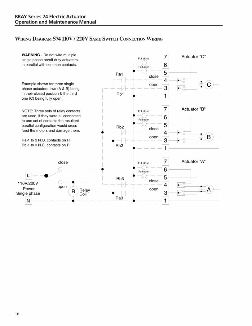
WIRING DIAGRAM S74 110V / 220V SAME SWITCH CONNECTION WIRING
13456
C
1
543
6
B
1
543
6
A
Full close
close
open
Full open
close
open
close
open
Ra1
Rb1
Rb2
Ra2
Rb3
Ra3
close
openR
110V/220VPower
L
N
Single phase
7
7
7
WARNING - Do not wire multiple single phase on/off duty actuators in parallel with common contacts.
Example shown for three single phase actuators, two (A & B) being in their closed position & the third one (C) being fully open.
NOTE: Three sets of relay contacts are used, if they were all connected to one set of contacts the resultant parallel configuration would cross feed the motors and damage them.
Ra-1 to 3 N.O. contacts on RRb-1 to 3 N.C. contacts on R
Full close
Full open
Full close
Full open
Actuator "A"
Actuator "B"
Actuator "C"
RelayCoil
17
BRAY Series 74 Electric ActuatorOperation and Maintenance Manual
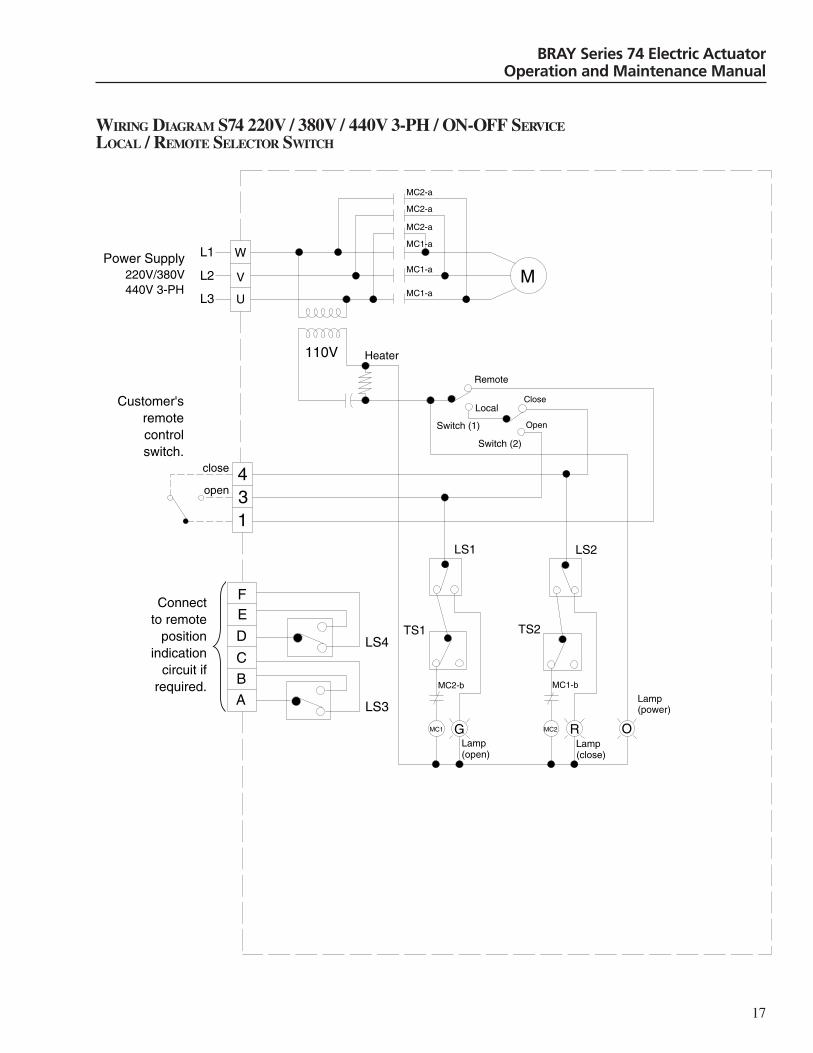
WIRING DIAGRAM S74 220V / 380V / 440V 3-PH / ON-OFF SERVICELOCAL / REMOTE SELECTOR SWITCH
A
B
C
EF
LS1 LS2
D
W
V
U
Heater
Switch (1)
Switch (2)
Remote
LocalClose
Open
G R OLamp(open)
Lamp(close)
Lamp(power)
110V
134
TS1 TS2
M
MC1-a
MC2-a
MC2-a
MC2-a
MC1-a
MC1-a
MC2-b MC1-b
MC1 MC2
open
close
LS4
LS3
Power Supply220V/380V440V 3-PH
L1
L2
L3
Customer's remote control switch.
Connectto remote
position indication
circuit if required.
18
BRAY Series 74 Electric ActuatorOperation and Maintenance Manual
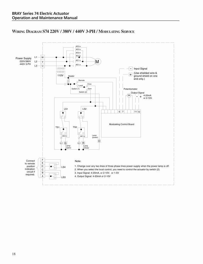
WIRING DIAGRAM S74 220V / 380V / 440V 3-PH / MODULATING SERVICE
6 7 11 12
+
-
5K
Modulating Control Board
LS1
Potentiometer
Output Signal 4-20mAor 2-10V.
TS1 TS2
LS2
W
V
U
Heater
Switch (1)
Switch (2)
Remote
LocalClose
Open
M
G RO
Lamp(open)
Lamp(close)
Lamp(power)
Power Supply220V/380V
Note:
1. Change over any two lines of three phase lines power supply when the power lamp is off.
2. When you select the local control, you need to control the actuator by switch (2).
3. Input Signal: 4-20mA, or 2-10V, or 1-5V
4. Output Signal: 4-20mA or 2-10V
440V 3-PH
110V
- +
MC2-a
MC1-a
MC2-a
MC2-a
MC1-a
L1
L2
L3MC1-a
MC1-bMC2-b
MC1 MC2
CB
A
FED
Input Signal
(Use shielded wire & ground shield on one end only.)
Connectto remote
position indication
circuit if required.
LS3
LS4
19
BRAY Series 74 Electric ActuatorOperation and Maintenance Manual
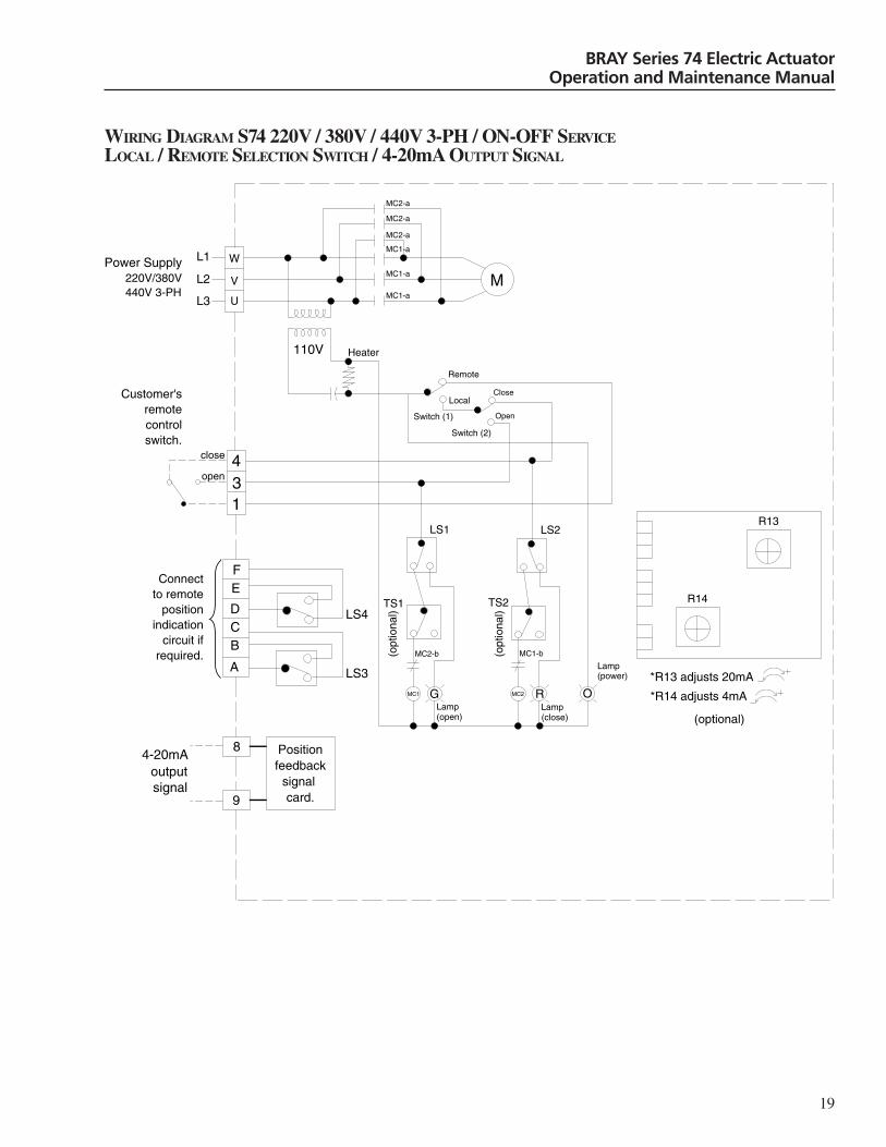
WIRING DIAGRAM S74 220V / 380V / 440V 3-PH / ON-OFF SERVICELOCAL / REMOTE SELECTION SWITCH / 4-20mA OUTPUT SIGNAL
A
BC
EF
(opt
iona
l)
(opt
iona
l)
LS1 LS2
D
W
V
U
Heater
Switch (1)
Switch (2)
Remote
LocalClose
Open
G R OLamp(open)
Lamp(close)
Lamp(power)
110V
134
TS1 TS2
M
MC1-a
MC2-a
MC2-a
MC2-a
MC1-a
MC1-a
MC2-b MC1-b
MC1 MC2
R13
R14
*R13 adjusts 20mA
*R14 adjusts 4mA
8
9
4-20mAoutputsignal
(optional)
open
close
Customer's remote control switch.
Connectto remote
position indication
circuit if required.
Positionfeedback
signal card.
LS3
LS4
Power Supply220V/380V440V 3-PH
L1
L2
L3
20
BRAY Series 74 Electric ActuatorOperation and Maintenance Manual
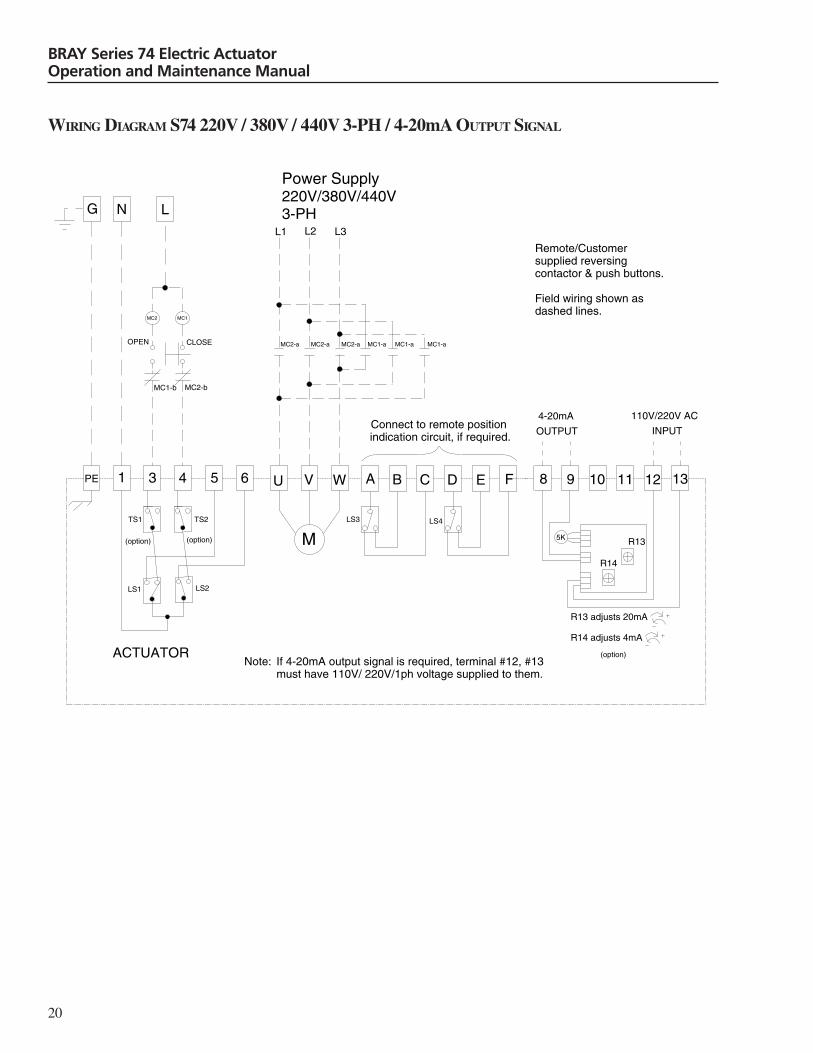
WIRING DIAGRAM S74 220V / 380V / 440V 3-PH / 4-20mA OUTPUT SIGNAL
1 3 4 U V W 8 9 10 11 12 13
N L
ACTUATOR
MC2
MC1-b MC2-b
OPEN CLOSE
M
L1 L2 L3
MC2-a
TS1 TS2
LS1 LS2
PE
(option) (option)
Power Supply220V/380V/440V3-PH
MC1
MC2-a MC2-a MC1-a MC1-a MC1-a
110V/220V AC
INPUT
R13 adjusts 20mA
R14 adjusts 4mA
R13
R14
5K
4-20mA
OUTPUT
Note: If 4-20mA output signal is required, terminal #12, #13 must have 110V/ 220V/1ph voltage supplied to them.
A
LS3
B
LS4
C D E F
(option)
5 6
Connect to remote position indication circuit, if required.
Remote/Customersupplied reversingcontactor & push buttons.
Field wiring shown as dashed lines.
G

21
BRAY Series 74 Electric ActuatorOperation and Maintenance Manual
WIRING DIAGRAM S74 24V DC
1 3 4 7 A B C E F
+ -Power Supply
24V DC
G
LS3 LS4
HE
AT
ER
MACTUATOR
TS1 TS2
DPE
LS2LS1
1 2 3 4 5 6 7
24V DC
(opt
iona
l)
(opt
iona
l)
5 6
Ful
ly o
pen
ind.
Lam
p
Ful
ly c
lose
d in
d. L
ampCS
OPEN
COM
COM COM
COM
NO NC NO NC NCNO
COM NC NO COM NC NO
NO NC
CLOSE Connect to remote position indication circuit, if required.
Actuator External/Field Wiringshown with dashed lines
Actuator drawn for it's fully closed position (close travel switch "LS2has been tripped)
22
BRAY Series 74 Electric ActuatorOperation and Maintenance Manual
WIRING DIAGRAM S74 24V AC
1 3 4 7 A B C E F
N L
Power Supply24V AC
LS3 LS4
MACTUATOR
TS1 TS2
DPE
LS2LS1
1 2 3 4 5 6 7
24V DC
5 6
CS
OPEN
COM
COM COM
COM
NO NC NO NC NO
COM NC NO COM NC NO
NO NCNC
CLOSE
+ -
HE
AT
ER
(opt
iona
l)
(opt
iona
l)
Ful
ly o
pen
ind.
Lam
p
Ful
ly c
lose
d in
d. L
amp
Connect to remote position indication circuit, if required.
G
23
BRAY Series 74 Electric ActuatorOperation and Maintenance Manual
WIRING DIAGRAM S74 220V/380V/440V/480V AC 3-PH
1 3 4 U V W A B C D E F
N L
LS3
NO NC
COM
NO NC
COM
LS4
3-PH
ACTUATOR
MC2
MC1-b MC2-b
OPEN CLOSE
M
L1 L2 L3
T1 T2 T3
MC2-a
TS1 TS2
LS1 LS2
PE
Power Supply220/380/440/480VAC
3-phase
MC1
MC2-a MC2-a MC1-a MC1-a MC1-a
6 95 8
HE
AT
ER
G
Open Lamp
CloseLamp
Customer supplied reversing contactor & control devices.
24
BRAY Series 74 Electric ActuatorOperation and Maintenance Manual
WIRING DIAGRAM S74 24V DC / MODULATING SERVICE
1 2 3 4 5 6 7 8 9 10 11 12
-+
+
-
5K
A B C D E
Modulating Control Board
Position Feedback Signal
Input Signal Power Supply
24V DC
LS4LS3
Note:(1) Input Signal : 4-20mA or 1-5V or 2-10V.(2) Output Signal : 4-20mA or 2-10V.
LS2LS1
TS2TS1
F
7654321
M
24V DC
(opt
iona
l)
(opt
iona
l)
(Use shielded wire & ground shield on one end only.)
Heater
- +
A B
FNO NC NO NC
NO NC NO NC
COMCOM
COM
NO NC
COM
NO NC
COM
COM
G
INT POT
Connect to remote position indication circuit, if required.

25
BRAY Series 74 Electric ActuatorOperation and Maintenance Manual
WIRING DIAGRAM S74 24V AC / MODULATING SERVICE
1 2 3 4 5 6 7 8 9 10 11 12
N
L
+
-
5K
A B C D E
Modulating Control Board
24V AC
LS4LS3
Note:(1) Input Signal : 4-20mA or 1-5V or 2-10V(2) Output Signal : 4-20mA or 2-10V
LS2LS1
TS2TS1
F
7654321
M
(opt
iona
l)
(opt
iona
l)
24V DC
-~
+
~
Heater
F
A B- +
Position Feedback Signal
INT POT
NO NC
COM
NO NC
COM
NO NC
COM
NO NC
COM
NO NC
COM
NO NC
COM
Connect to remote position indication circuit, if required.
Power Supply
G
Input Signal
(Use shielded wire & ground shield on one end only.)

A Division of BRAY INTERNATIONAL, Inc.13333 Westland East Blvd. Houston, Texas 77041281/894-5454 FAX 281/894-9499 www.bray.com
Bray® is a registered trademark of BRAY INTERNATIONAL, Inc.© 2006 Bray International. All rights reserved. OM-74-001 7/2006
R
CONTROLS
204450