r e p o r t on technical visit to subang-kelana link pro j...
TRANSCRIPT
JURUTERA, October 200740
R E P O RTCivil & Structural Engineering Technical Division
WOW! If you have an opportunity towitness three diff e rent types of
bridge superstru c t u re constru c t i o nmethods in a single technical visit, willyou miss it?
Needless to say, most stru c t u r a lengineers will say "No!". In addition tothe good opportunity which will notre-appear again in the next few years,the site is just a few kilometres awayf rom the city and participants do notneed to endure a long journey to re a c hthe destination. There are around sixtyover IEM members on this visit, mostof whom with strong interest in thedesign and construction of bridges t ru c t u res. They responded eagerly tothe invitation to participate in thetechnical visit to Subang-Kelana LinkP roject, organised by IEM Civil andS t ructural Engineering Te c h n i c a lDivision on the Saturday morning of 19May 2007.
Just a short drive from IEM Buildingin Petaling Jaya, the IEM delegatesreached the site at around 9.30a.m. andw e re warmly welcomed by the host. Ir.Bakri Bin. Ishak from Ahmad ZakiR e s o u rces Berhad, who presented ac o m p rehensive briefing to the delegateslasting around one hour. It was followedby a lively question and answer sessionb e f o re the participants were led to thefield to witness the three diff e rent types ofbridge construction methods at variouslocations within the project vicinity.
The main scope of the project is toconstruct a four-lane dual carriagewayelevated section from Jalan Subang toKESAS Highway at Subang Jaya crossingthe Federal Highway. The total length ofthe mainline structure with a width of20.6m is around 1.5km. The targeted dateof completion is December 2008. For the
ease of contract management andadministration, the project was dividedinto three sections.
Section A : From Kewajipan Roundaboutto KESAS Highway
Section B: F rom Mesiniaga Building crossing Federal Highway to Jalan Subang
Section C: Six (6) numbers of rampconnecting the existing roads to the new elevated main lineat various locations
N o t e :a . The biggest pilecap’s dimensions are
25m x 20m x 3.75m with a totalc o n c rete volume of 1856m3.
b .The tallest pier is located at Bulatan Kewajipan with a height of 29m.
SUPERSTRUCTURET h e re are three diff e rent types ofconstruction method for the constructionof the bridge superstructure.
Section A:P recast concrete segmental box gird e rand erected by balance cantilevermethod using gantry.
Section B:Balance cantilever in-situ concre t esegmental box girder by using travellingf o r m w o r k .
Section C:Continuous span cast in-situ concrete boxg i rder fully supported on falseworks.
PRECAST CONCRETESEGMENTAL BOX GIRDERS This is the mainline of the carriagewayconsisting of 33-span elevated stru c t u rewith a typical span of either 40m or 47m.The typical segment dimensions are 20.8mwidth and 2.2m length. A total of 747numbers of precast concrete segmentweights varies between 70 and 110 tonnes tobe cast and erected for the elevated section.
The precast segments are to be ere c t e dby a 111.75m length, 300 tonnes gantry ina balance cantilever manner. The typicalsequence for the main activities ofs u p e r s t ru c t u re construction is as follows.a. Install the pier segment (N)b. Install one segment at each end of the
pier segment (N-1 and N+1) one afteranother.
c. Hold the installed segments by usingtemporary prestressed bars.
d. Install another one segment at eachend of the cantilever (N-2 and N+2)one after another.
e. Hold the installed segments by usingtemporary prestressed bars.
f. Install and stress the cantilever prestressed tendons.
g . Release the temporary pre s t ressed bars.h. Repeat items (b) to (g) above until the
particular span of cantilever is ere c t e d
R e p o rt on Technical Visit to Subang-Kelana L ink Pro j e c t......................................................................................................................................................................................................................................................................
By: Engr. Li Thang Fai, MIEM, P.Eng.
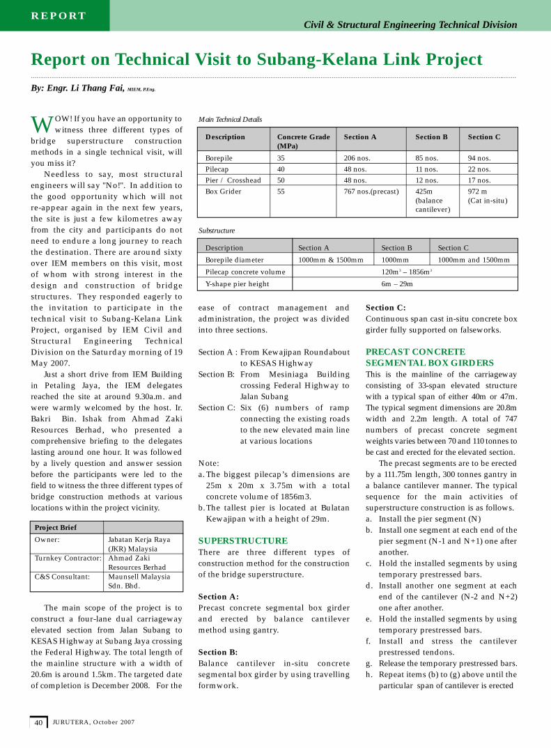
Description Concrete Grade Section A Section B Section C(MPa)
Borepile 35 206 nos. 85 nos. 94 nos.Pilecap 40 48 nos. 11 nos. 22 nos.Pier / Crosshead 50 48 nos. 12 nos. 17 nos.Box Grider 55 767 nos.(precast) 425m 972 m
(balance (Cat in-situ)cantilever)
S u b s t r u c t u re
Description Section A Section B Section C
Borepile diameter 1000mm & 1500mm 1000mm 1000mm and 1500mm
Pilecap concrete volume 120m3 – 1856m3
Y-shape pier height 6m – 29m
Project Brief
Owner: Jabatan Kerja Raya(JKR) Malaysia
Turnkey Contractor: Ahmad Zaki Resources Berhad
C&S Consultant: Maunsell Malaysia Sdn. Bhd.
Main Technical Details

JURUTERA, October 2007 41
R E P O RTCivil & Structural Engineering Technical Division
Then, the gantry will be launchedf o r w a rd to the next pier and proceed tothe erection of the following cantilever.Upon completion of the erection of twoadjacent cantilevers, the gap betweenthe cantilevers of around 200mmwould be cast by in-situ concrete andform a complete span. Continuityp re s t ressed tendons would then beinstalled and stressed. It was notedthat internal pre s t ressing is used for allthe cantilever tendons while externalp re s t ressing is adopted for all thecontinuity tendons.
CAST IN-SITU CONCRETESEGMENTAL BOX GIRDERSThe bridge over Federal Highwayconsists of two identical five spanscontinuous single cell cast in-situc o n c rete box girders with a spanconfiguration of 55m-95m-130m-90m-55m. The box girders are monolithic atthe two centre piers and are supportedon bearings at other piers. The cast in-situ concrete segmental box gird e r swith a depth variation between 7.2m(at support) and 2.6m (at midspan) willbe constructed in balance cantilevermethod by using travelling formwork.
There are fifteen segments on eachside of the pier with the first sevensegment length at 3.1m while the balanceeight segments is 4.6m length each.
Form traveller is adopted for thec o n s t ruction of the Federal Highwayc rossing. A form traveller is a systemw h e reby the formwork for the segmentthat is to be cast is held by the framesclinging on to the segments that havebeen cast earlier.
The cantilever construction startedo ff by constructing the pier segment orusually known as ‘hammerhead’. Inthis particular case, the ‘hammerh e a d ’is 14m in length and 7.2m in depth. Itwas constructed by using in-situc o n c rete fully supported onfalseworks. Upon the completion of the‘ h a m m e rhead’, the form travellersw e re erected on the cast deck andready for subsequent ‘travelling’c o n s t ruction. The typical sequence forthe main activities of superstru c t u rec o n s t ruction is as follows.a. Launch the travellers forward and fix
them on the earlier cast bridge decks.
Figure 1: Y-shape pier at Section 1
Figure 3: “Travelling” construction in progress at Section 2
Figure 2: Precsat concrete segmental construction at Section 1

JURUTERA, October 200742
R E P O RTCivil & Structural Engineering Technical Division
b. Survey and adjust the formwork tothe required position.
c. Install re i n f o rcement bars andp re s t ressed tendon components (usually without threading inprestressing strand at the moment).
d. Cast the segments.e. C o n c rete curing and install pre s t ressing
strands to thepre s t ressed ducts which a re to bestressed for the particular stage of constru c t i o n .
f. Upon the attainment of concre t etransfer strength, stress thedesignated prestressed tendons.
g. Release formwork and back to item(a) above.
It was informed that the cantileverc o n s t ruction started around twomonths ago and a cycle time of aro u n dten working days was observed.H o w e v e r, it was believed that whenthe site team had completed the‘learning curve’ process, and inaddition to the fact that the segmentsbecome shallower when the cantilevera p p roaches the misdpan, the cycle
time can be re-duced to around 6working days.
There are a totalof four cantileversto be constru c t e d .In view that onlytwo sets of formtraveller were beingadopted for the
c o n s t ruction of the cantilevers, aspecified construction sequence wasplanned for implementation. Firstly,the two parallel cantilevers at JalanSubang side were to be built. Then thetwo sets of form traveller would berelocated to Subang Jaya side for thec o n s t ruction of the balance twocantilevers. It was foreseen that thecompleted cantilevers at the JalanSubang side will be ‘free cantilevering’for a period of around six monthsb e f o re joining with the othercantilevers ‘growing’ from the otherside of Federal Highway.
CAST IN-SITU CONCRETE BOX GIRDERSThere are six numbers of ramps spanningbetween 40 m and 58m which are madeof cast in-situ concrete continuous boxgirders. All the box girders were cast onflaseworks in a ‘span by span’ method.The typical sequence for the mainactivities of superstructure constructionis as follows.a. Prepare falseworks and formworks for
a designated length with an endconstruction joint end.
b. Fix the bar re i n f o rcements andprestressed tendons.
c. Cast the particular designated length.d. Concrete curing.e. Upon the attainment of concre t e
transfer strength, stress the prestressed tendons.
f. Remove the falseworks and formworks.g. Relocate the falseworks and
formworks forward and back to item(a) above.
The overall pre s t ressed tendonlayout was detailed in a manner inwhich the location of the designatedc o n s t ruction joint positions were takeninto consideration. A detail of‘overlapped tendons’ was adopted forp roviding continuity to the bridges u p e r s t ru c t u re .
At the time of visit, it was observedthat the main construction works on fournumber ramps had been completed. ■
ACKNOWLEDGEMENT
The Civil and Structural EngineeringTechnical Division wishes to thankJabatan Kerja Raya Malaysia, A h m a dZaki Resources Berhad and MaunsellMalaysia Sdn. Bhd. for their kindcooperation and warm hospitality inmaking the technical visit a reality and anenjoyable experience for IEM members.
Figure 4: A completed prestressed concrete box grider ramp under Section 3