r-. calculations of inhomogeneous ground effects in ... · pdf fileerdc/crrel tr-04-11 april...
TRANSCRIPT

USArmy Corpsof EngineerseEngineer Reseach andDevelopment Center
r-. Calculations of Inhomogeneous* Ground Effects In Outdoor
Sound Propagation Using theBoundary Element Method (BEM)
Donald G. Albert April 2004
fi
0==
)r I
0]
I'-
App oed*r public release; distilbution is unlimited.

Front cover: Composite photograph of the test site used to collect measurement data to verify theBoundary Element Method for acoustic propagation over inhomogeneous ground.By removing the natural snow cover, the surface impedance in specific areas isgreatly increased. Here the remaining snow patch is 30 meters wide, and contains afew wild deer tracks.

ERDC/CRREL TR-04-11April 2004
Calculations of InhomogeneousGround Effects in OutdoorSound Propagation Using theBoundary Element Method (BEM)
Donald G. Albert
Approved for public release; distribution is unlimited.
Prepared for U.S. ARMY CORPS OF ENGINEERS
ABSTRACT
This report summarizes the results of a study to calculate the effect of inhomogeneous ground imped-ance on acoustic wave propagation. The boundary element method was used to investigate the effect ofsnow or bare ground patches along the acoustic propagation path. This method can be used to calculatethe effect of inhomogeneities in the propagation medium with a relatively small computational effortcompared to many other methods (for example, the finite difference method). The boundary elementmethod is first verified by showing agreement with a published result, and then shown to give goodagreement with experimental measurements.
DISCLAIMER: The contents of this report are not to be used for advertising, publication, or promotional purposes.Citation of trade names does not constitute an official endorsement or approval of the use of such commercial products.All product names and trademarks cited are the property of their respective owners. The findings of this report are not tobe construed as an official Department of the Army position unless so designated by other authorized documents.DESTROY THIS REPORT WHEN IT IS NO LONGER NEEDED. DO NOT RETURN TO THE ORIGINATOR.

Calculations of Inhomogeneous Ground Effects
CONTENTS
Preface .......................................................................................................... . . iv
1 Introduction ............................................................................................... 1
2 The Boundary Element Method (BEM) ..................................................... 2
Open BEM Code and Modifications .......................................................... 5
Assumptions and Limitations ...................................................................... 5
3 V erification ................................................................................................ 6
4 Results for Inhomogeneous Ground Impedance ......................................... 7
Examples for Snow Covers ........................................................................ 7
Comparison with Measured Data ............................................................... 7
5 Sum m ary .................................................................................................. 12
ILLUSTRATIONS
Figure 1. (Top) Geometry in the generic boundary element method. Theboundary Fcan have any desired shape. (Bottom) Geometry for the snowcover calculations in this paper ................................................................. 3
Figure 2. Verification of the MATLAB Open BEM code results by comparisonwith previously published results ............................................................ 6
Figure 3. Excess attenuation calculated for sound propagation over adiscontinuous snow cover ........................................................................ 8
Figure 4. Excess attenuation calculated for sound propagation over discon-tinuous snow covers of various dimensions ............................................... 9
Figure 5. Measured excess attenuation for sound propagation over homo-geneous and inhomogeneous ground ..................................................... 10
Figure 6. Theoretical prediction of excess attenuation for sound propagationover homogeneous and inhomogeneous ground, calculated using theB E M ............................................................................................................. 11

iv ERDC/CRREL TR-04-11
PREFACE
This report was prepared by Dr. Donald G. Albert, Geophysicist,Geophysical Sciences Division, Cold Regions Research and EngineeringLaboratory (CRREL), U.S. Army Engineer Research and Development Center(ERDC), Hanover, New Hampshire.
The experiments were conducted with the assistance of Dave Carbee, SteveDecato, Frank Perron, and Dr. Joyce Nagle under AT24 work unit "Seismic andAcoustic Wave Propagation in Cold Regions." The author thanks Leon Stetsonfor use of the field site; Dr. Peter Juhl, University of Southern Denmark, forproviding the Open BEM code; and Dr. Susanna Quiros y Alpera and othersfor their contributions to this code. Funding for these calculations was providedby Dr. Mark Moran under AT42 project "Support to Acoustic PropagationModeling." Technical reviews were provided by Dr. Tom Anderson and Dr.Keith Wilson. This work is supported by the Directorate of Research andDevelopment, U.S. Army Corps of Engineers.
The Commander of the Engineer Research and Development Center isColonel James R. Rowan, EN. The Director is Dr. James R. Houston.

Calculations of Inhomogeneous Ground Effectsin Outdoor Sound Propagation
Using the Boundary Element Method (BEM)
DONALD G. ALBERT
1 INTRODUCTION
An understanding of the interaction of sound energy with the ground is im-portant in predicting noise propagation through the atmosphere (Embleton et al.1976, Embleton et al. 1983, Attenborough 1992, Embleton 1996, Sutherland andDaigle 1997). It affects predictions of traffic, industrial, and blasting noise levels,and is important in mitigating and assessing environmental impacts of militaryactivities. In realistic situations, noise or sound often propagates horizontallyover ground with varying surface properties, including vegetation, paving, etc.In this study, the boundary element method was used to study sound propagationover laterally inhomogeneous ground impedance. General effects and computa-tional behaviors are investigated for simple cases, and the method is compared tomeasured data.

2 ERDC/CRREL TR-04-11
2 THE BOUNDARY ELEMENT METHOD (BEM)
The boundary element method has been frequently used to solve problems inacoustics (Jensen et al. 1994, Estorff 2000, Xu 2001). Recently, the method hasbeen applied to traffic noise problems, allowing the effect of different groundsurfaces (paved roads or natural ground cover), topography, and various screensdesigned to mitigate noise to be evaluated (Hothersall et al. 1991, Hothersall andHarriott 1995, Chandler-Wilde 1997, Defrance and Premat 2001). Chandler-Wilde (Chandler-Wilde 1997) has presented a thorough review of the method'sapplication to outdoor sound problems.
In this section we briefly summarize the boundary element method, follow-ing Chandler-Wilde (Chandler-Wilde 1997). This reference and the book by Wu(Wu 2000, Chapters 2 and 3) both provide derivations of the BEM equations,which are not repeated here. In a homogeneous space, the Helmholtz equation is
V 2p+k 2p=0 (1)
where p is the pressure, k = woic is the wavenumber, co the radial frequency, and cthe acoustic wave in air. For a locally reacting porous medium on the ground, theimpedance boundary condition can be written as
LP =ikpfi (2)an
where fi = lIZ (= 0 for a rigid surface) is the admittance normalized to air. (Z isthe impedance.) The Sommerfeld radiation condition is also specified. In twodimensions with a line source, the solution of Equation 1 is
4 0
where R is the source-receiver distance and H(') the Hankel function of the firstkind. Here, e-'" time dependence has been assumed. Chandler-Wilde shows thatthe same methods used to solve the two-dimensional case presented here can alsobe used to solve three-dimensional problems for a point source; of course, theseproblems would require much more computational effort because of the greaternumber of points in the three-dimensional space.

Calculations of Inhomogeneous Ground Effects 3
Y Source *r
r
x
2 'Source
> 1Snow cover
20M ,, 0000 0
Rigid Boundary
0 30 60 90Distance (m)
Figure 1. (Top) Geometry in the generic boundary element method. Theboundary Fcan have any desired shape. (Bottom) Geometry for the snowcover calculations in this paper.
The boundary integral equation can be derived from the Helmholtz equationby application of Green's second identity. For a source at r0 and a scattering bodywith boundary /and admittance At the resultant pressure at any point r externalto the body (Fig. 1) is given by
b(r)p(r,ro)=G(r, ro)+ I an( r,'r) _ikOlG(rsr)] p(r•,r) dSr) (4)
This is Chandler-Wilde's equation (1). The coefficient b(r) is a "receiverboundary location coefficient" with a value of 1 if r is not on the boundary, anda value of 1/2 if r is on a flat boundary. G is a solution for the pressure withoutthe scattering object. For example, in free space, G is just the solution given byEquation 3. Equation 4 shows that the pressure can be calculated from the pres-

4 ERDC/CRREL TR-04-11
sure values on the surface of the scattering body, and is the fundamental equationused in BEM calculations.
For outdoor sound propagation with a flat, homogeneous finite impedanceboundary at y = 0, Equation 4 still holds if we take G to represent the pressurewhen the ground is present. Chandler-Wilde and Hothersall (Chandler-Wilde andHothersall 1995) have shown that this solution is
G(rr=-- H() (kR) -4iH') (kR')+ B(r,r0 ) (5)4 0 40
where R' is the image source (x0, - yo) to r distance. The first two terms are thedirect ray and the ray from the image source. The term B gives the contributionof the boundary, including the specular reflection and any surface wave termsthat might be present (depending on the boundary material parameters). It con-tains the boundary loss term used in other formulations of the problem. If theboundary is rigid, B = 0 and the perfect reflection is included in the second termof Equation 5. Equations 4 and 5 are used for the calculations in this paper.
Equation 4 is solved numerically by dividing the boundary F into discreteelements (usually the element length < wavelength/5), assuming the pressure atthe boundary element from a source at rO, p(r-element, rO), is constant over theentire element, and solving for the pressures over the boundary F. Then Equation4 with the known pressures on the boundary is solved to find the pressure at anyother desired point. Thus the boundary of a snow cover (as shown in the bottompanel of Figure 1) is subdivided into a series of small elements, and the aboveprocedure is used to find the acoustic pressure field with the snow cover present.Wu (Wu 2000) discusses various discretization schemes; in acoustic problems asimple linear element approximation is usually used. While non-unique solutionsexist at the resonant frequencies of the scattering objects, these ambiguities areeasily resolved by calculating a few interior points, a procedure termed theCHIEF method (Wu 2000).
A primary advantage of the BEM method is that only the scattering objectsneed to be discretized, instead of the full propagation space as for the full finitedifference or finite element methods, offering a large savings in computationaleffort. The cost of BEM calculations is dependent on the size of the scattererswith respect to the wavelength, so it is most efficient where the scatterers arerelatively small. Because the element size depends on the wavelength, doublingthe frequency will double the computation time.

Calculations of Inhomogeneous Ground Effects 5
Open BEM Code and Modifications
There are many codes available for solving acoustic problems using BEM.For example, Fortran codes are provided in books (Wu 2000) and at various Websites. For this paper, the author used a code called Open BEM that was written inMatlab." Although an interpreted language, and thus slow compared to acompiled language such as Fortran, Matlab is much easier to program andprovides good visualization tools. This Matlab code has been used to solve manyacoustic problems, including previous calculations in outdoor sound propagation(Quiros y Alpera and Jacobsen 2002).
The Open BEM code provides a solution method for two-dimensional prob-lems using Equations 4 and 5 discussed above. This code has been modified bythe author to use boundary admittance calculated from Attenborough's groundimpedance model (Attenborough 1985) instead of the Delany Bazley model(Delaney and Bazley 1970) as the latter model does not work well for snow.Currently, the Attenborough model is implemented only as a lookup table, withthe admittance values actually calculated separately using a Fortran code.
Assumptions and Limitations
For the problems discussed in this report, a homogeneous atmosphere isassumed. Because the ground at the experimental site was frozen, we assumethat it is rigid in the model, and that the snow-cover properties are homogeneous.Finally, we restrict the calculations to a two-dimensional geometry. All of theseassumptions can be relaxed in the boundary element method, but at the cost ofincreased computational time.
* Personal communication, P. Juhl, University of Southern Denmark, 2001.

6 ERDC/CRREL TR-04-11
3 VERIFICATION
To become familiar with the Open BEM code and check its operation, anexample taken from the published literature produced by authors not associatedwith Open BEM was calculated. The example is a barrier above a finite impedanceplane with a flow resistivity of 250 kN s m-4. The published result (Hothersall et al.1991) and the geometry are shown in Figure 2, along with the result calculatedusing the Open BEM code. The calculations agree with the published results. Thiscalculation took about 4.5 minutes on a 2 GHz personal computer.
K)1
0 00 $0 NMV 400
a. Published BEM result (from Hothersall et al. 1991) for the geometryshown on the graph. Dots are BEM calculations, lines are measurements.
1 0
b. Results of the current Open BEM code for the same situation.
Figure 2. Verification of the MATLAB Open BEM code results by compari-son with previously published results.

Calculations of Inhomogeneous Ground Effects 7
4 RESULTS FOR INHOMOGENEOUS GROUND IMPEDANCE
In this section the results of the BEM calculations are presented. Since theground is usually frozen during the winter, in each case we assume that theground is rigid (thus B = 0 in Equation 5). A snow cover with a depth of 20 cmand an effective flow resistivity of 7000 Pa m-2 s is included as shown in Figure1, bottom. This snow cover is treated as a scattering object placed on top of therigid ground surface, and the effect of changing the dimensions and location ofthe snow cover is studied. A line source is located 1 m above the surface at zerodistance. The excess attenuation, defined as the signal level difference from thelevel in free space (that is, without a ground surface or any scatterers present) atthe same distance, is shown in all cases.
Examples for Snow Covers
Figure 3 shows an example of the excess attenuation calculated using BEMfor propagation over a discontinuous snow cover. In this example, the snowcover is located 30 to 60 m away from the source. The results show an excessattenuation of +6 dB (that is, enhancement by a factor of two) for distances of 0to 30 m from the source at all frequencies, representing the reflection from therigid boundary. When the snow layer is reached, the excess attenuation becomesgreater, with a value of about 0 dB for frequencies below 100 Hz and reaching-30 dB for higher frequencies. This frequency-dependent attenuation has beenobserved experimentally and is one of the main characteristics of propagationover homogeneous snow covers (Albert and Orcutt 1990). The low-pass filteringeffect of the snow remains as the propagation continues over bare ground beyondthe snow layer. This calculation took five minutes for the 19 frequencies shownin Figure 3.
Additional examples of the snow-cover effect, with the snow at differentlocations along the propagation path, are shown in Figure 4. The excess attenua-tion is always greater over the snow cover, but remains large at high frequencieswhen the propagation continues over rigid ground. The computation time forthese examples ranged from 5 to 34 minutes, depending on the snow-coverlength (30 to 90 m).
Comparison with Measured Data
An experiment was conducted to investigate homogeneous ground outdoorsusing a natural snow cover (Albert 2000). A blank pistol, held 1 m above theground surface, was used as the source of the acoustic waves, which were digi-

8 ERDC/CRREL TR-04-11
tally recorded by a microphone at the ground or snow surface 60 m away fromthe source. This measurement was repeated with four different ground conditionsbetween the source and receiver. If we let S represent propagation over 30 m ofsnow, and G propagation over 30 m of plowed ground, the configurations (read-ing from source to receiver) were SS (undisturbed snow), SG (snow followed byplowed ground), GS (ground then snow), and GG (all plowed ground).
10-
0.1
.401
0
100
200
3W 0"
400 .- 60
90Soo 120
Frequency (Hz) DtWae (m)
Figure 3. Excess attenuation calculated for sound propagation over adiscontinuous snow cover. The axis on the left is the frequency (Hz)while the axis on the right is the distance (m). The snow cover, locatedbetween 30 m and 90 m from the source, was 20 cm deep and had aneffective flow resistivity of 7000 Pa m-2 s.
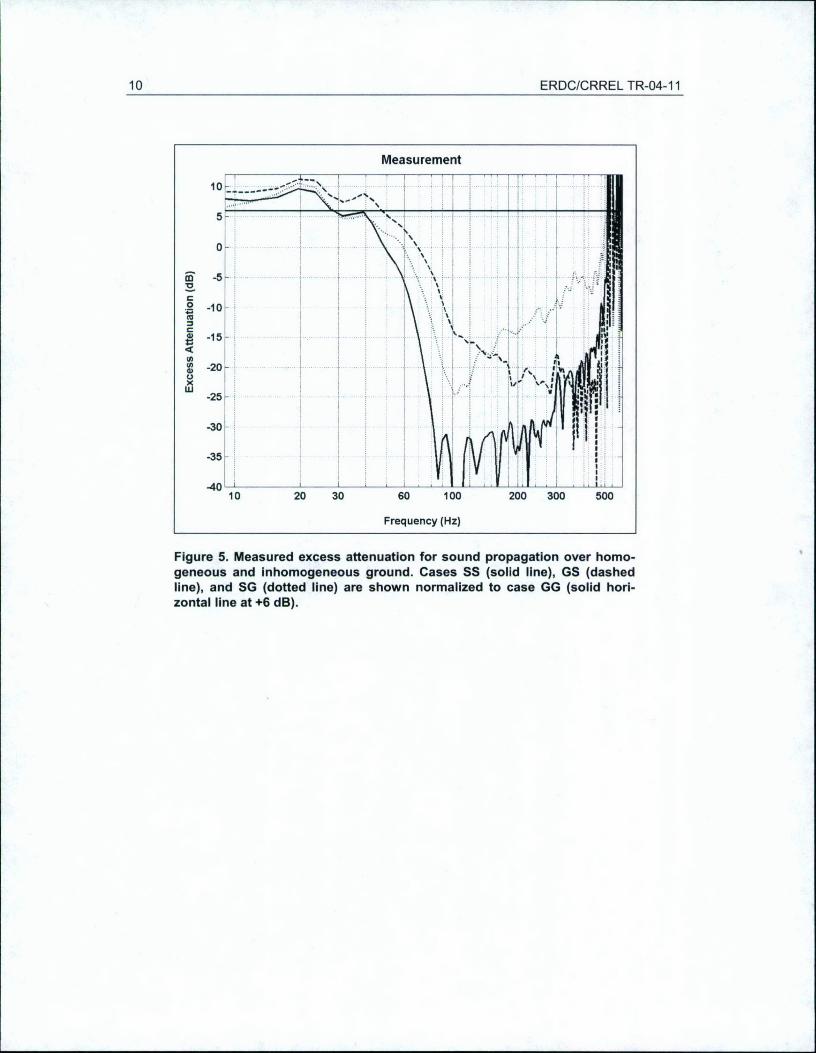
The pistol shot waveforms were Fourier transformed and the transformcorresponding to the GG case, representing a rigid ground surface, was adjustedto +6 dB to account for the source strength, receiver response, and geometricspreading of the wave. The same adjustment was applied to the other transforms,resulting in the excess attenuation measurements shown in Figure 5. As expected,the excess attenuation is large for higher frequencies traveling over snow, withthe largest excess attenuation occurring for the longer path over snow (SS). Inthese measurements, the attenuation increases for frequencies of 50 Hz andabove.

Calculations of Inhomogeneous Ground Effects 9
A B
0-0
-20-20
-40 4
100 ?0020300-2
40 0400 60500 120 90 500 120 90
C D
_20-. -20,
-40
200 0Y300 >_ 03
400 3050500 120 98 6 5W0 1290 6
Figure 4. Excess attenuation calculated for sound propagation over dis-continuous snow covers of various dimensions. For each plot, the axis onthe left Is the frequency (Hz) while the axis on the right is the distance (m).The snow cover was located between -30 m and 30 m (A), -30 m and 60 m(B), +30 m and 60 m (C), and 30 m and 90 m (D).
Theoretical predictions for these ground situations and geometries werecalculated using the boundary element method and the results are shown inFigure 6. In these calculations the snow cover thickness was 20 cm and theeffective flow resistivity was 7000 Pa m-2 s. Although some of the details aredifferent (for example, the theoretical excess attenuation starts to increase at 100Hz instead of 50 Hz), there is good general agreement between the measured andtheoretical excess attenuations for these four situations. (The low apparent meas-ured attenuation for frequencies above 500 Hz is caused by a low signal-to-noiseratio from the very low output of the source at these frequencies.) Improvedagreement could probably be obtained by modifying the assumed snow para-meters, in particular by lowering the assumed excess flow resistivity and byincreasing the assumed snow depth. (The average measured snow depth was 28cm.)
10 ERDC/CRREL TR-04-11
Measurement
io_
0 -•0--
-25~
-30-(U
-35
-30
10 20 30 60 100 200 300 500
Frequency (Hz)
Figure 5. Measured excess attenuation for sound propagation over homo-geneous and inhomogeneous ground. Cases SS (solid line), GS (dashedline), and SG (dotted line) are shown normalized to case GG (solid hori-zontal line at +6 dB).

Calculations of Inhomogeneous Ground Effects 11
BEM Calculation10
•= i i i V I, .+
m I +: + ++4...-..........o l ..+ .... ... .......0 -10
-20 ,
U 4% ' "=U.3
-40
-.4,0 ' _ __ _ _ __ _ _ __ 1 L LL 1.;I
10 20 30 60 100 200 300 500Frequency (Hz)
Figure 6. Theoretical prediction of excess attenuation for sound propaga-tion over homogeneous and Inhomogeneous ground, calculated using theBEM. Cases SS (solid line), GS (dashed line), and SG (dotted line) areshown normalized to case GG (solid horizontal line at +6 dB).

12 ERDC/CRREL TR-04-11
5 SUMMARY
This report has demonstrated that the Open BEM code gives results inagreement with other BEM codes and with experimental measurements. Thecode provides a rapid, easy to use, accurate tool for calculating the effect ofinhomogeneous ground conditions and scattering from barriers on outdoorsound propagation.

Calculations of Inhomogeneous Ground Effects 13
REFERENCES
Albert, D.G. (2000) Acoustic pulse propagation over laterally inhomogeneousground. Journal of the Acoustical Society ofnAmerica, 108: 2650.
Albert, D.G., and J.A. Orcutt (1990) Acoustic pulse propagation above grass-land and snow: Comparison of theoretical and experimental waveforms. Journalof the Acoustical Society ofAmerica, 87: 93-100.
Attenborough, K. (1985) Acoustical impedance models for outdoor groundsurfaces. Journal of Sound and Vibration, 99: 521-544.
Attenborough, K. (1992) Ground parameter information for propagationmodeling. Journal of the Acoustical Society ofAmerica, 92: 418-427.
Chandler-Wilde, S.N. (1997) The boundary element method in outdoor noisepropagation. Proceedings, Institute ofAcoustics, 19 (Part 8): 27-50.
Chandler-Wilde, S.N., and D.C. Hothersall (1995) Efficient calculation of theGreen function for acoustic propagation above a homogeneous impedance plane.Journal of Sound and Vibration, 180: 705-724.
Defrance, J., and E. Premat (2001) Application of two impedance discontinuitymodels to real road traffic noise in cases in inhomogeneous air conditions. In17th International Congress ofAcoustics, Rome, Italy.
Delaney, M.E., and E.N. Bazley (1970) Acoustical properties of fibrous absorb-ent materials. Applied Acoustics, 3:105-116.
Embleton, T.F.W. (1996) Tutorial on sound propagation outdoors. Journal ofthe Acoustical Society ofAmerica, 100: 31-48.
Embleton, T.F.W., J.E. Piercy, and N. Olson (1976) Outdoor sound propa-gation over ground of finite impedance. Journal of the Acoustical Society ofAmerica, 59: 267-277.
Embleton, T.F.W., J.E. Piercy, and G.A. Daigle (1983) Effective flow resis-tivity of ground surfaces determined by acoustical measurements. Journal of theAcoustical Society of America, 74: 1239-1244.
Estorff, O.V., Ed. (2000) Boundary Elements in Acoustics: Advances andApplications. Boston: WIT Press, 476 p.
Hothersall, D.C., and J.N.B. Harriott (1995) Approximate models for soundpropagation above multi-impedance boundaries. Journal of the AcousticalSociety ofAmerica, 97: 918-926.

14 ERDC/CRREL TR-04-11
Hothersall, D.C., S.N. Chandler-Wilde, and M.N. Hajmirzae (1991) Effi-ciency of single noise barriers. Journal of Sound and Vibration, 146: 303-322.
Jensen, F.B., W.A. Kuperman, M.B. Porter, and H. Schmidt (1994) Com-putational Ocean Acoustics. New York: American Institute of Physics.
Quiros y Alpera, S., and F. Jacobsen (2002) Validation of a model for soundpropagation over non-flat terrain using BEM. In International Conference onSound and Vibration, Orlando, Florida.
Sutherland, L.C., and G.A. Daigle (1997) Atmospheric sound propagation. InEncyclopedia ofAcoustics (M.J. Crocker, Ed.), 341-365. New York: John Wiley& Sons, Inc.
Wu, T.W., Ed. (2000) Boundary Element Acoustics: Fundamentals and Com-puter Codes. Boston: WIT Press, 238 p.
Xu, S.Z. (2001) The Boundary Element Method in Geophysics. Tulsa, Okla-homa: Society of Exploration Geophysicists, 217 p.

DOCUMENTATION PAGE Form ApprovedREPORT DOUMEOMB No. 0704-0188Public reporting burden for this collection of information is estimated to average 1 hour per response, including the time for reviewing instructions, searching existing data sources. gathering and maintaining thedata needed, and completing and reviewing this collection of information. Send comments regarding this burden estimate or any other aspect of this collection of information, including suggestions for reducingthis burden to Department of Defense, Washington Headquarters Services, Directorate for Information Operations and Reports (0704-0188), 1215 Jefferson Davis Highway, Suite 1204, Arlington, VA 22202-4302.Respondents should be aware that notwithstanding any other provision of law, no person shall be subject to any penalty for failing to comply with a collection of information if it does not display a currently validOMB control number. PLEASE DO NOT RETURN YOUR FORM TO THE ABOVE ADDRESS.1. REPORT DATE (DD-MM-YY) 12. REPORT TYPE 3. DATES COVERED (From - To)April 2004 1 Technical Report
4. TITLE AND SUBTITLE 5a. CONTRACT NUMBER
Calculations of InhomogeneousGround Effects in Outdoor 5b. GRANT NUMBER
Sound Propagation Using theBoundary Element Method (BEM) sc. PROGRAM ELEMENT NUMBER
6. AUTHOR(S) 5d. PROJECT NUMBER
Donald G. Albert 5W. TASK NUMBER
5f. WORK UNIT NUMBER
7. PERFORMING ORGANIZATION NAME(S) AND ADDRESS(ES) 8. PERFORMING ORGANIZATION REPORT
U.S. Army Engineer Research and Development CenterCold Regions Research and Engineering Laboratory72 Lyme Road ERDC/CRREL TR-04-11Hanover, Nil 03755-1290
9. SPONSORING/MONITORING AGENCY NAME(S) AND ADDRESS(ES) 10. SPONSOR I MONITOR'S ACRONYM(S)
11. SPONSOR I MONITOR'S REPORTNUMBER(S)
12. DISTRIBUTION / AVAILABILITY STATEMENT
Approved for public release; distribution is unlimited.
Available from NTIS, Springfield, Virginia 22161.
13. SUPPLEMENTARY NOTES
14. ABSTRACT
This report summarizes the results of a study to calculate the effect of inhomogeneous ground impedance on acoustic wave propaga-tion. The boundary element method was used to investigate the effect of snow or bare ground patches along the acoustic propagationpath. This method can be used to calculate the effect of inhomogeneities in the propagation medium with a relatively small computationaleffort compared to many other methods (for example, the finite difference method). The boundary element method is first verified byshowing agreement with a published result, and then shown to give good agreement with experimental measurements.
IS. SUBJECT TERMS Acoustics Boundary Element Method Outdoor soundAcoustic sensors Complex terrain Wave propagationBEM Inhomogeneous
16. SECURITY CLASSIFICATION OF: 17. LIMITATION OF 18. NUMBER 19a. NAME OF RESPONSIBLE PERSONOF ABSTRACT OF PAGES
a. REPORT b. ABSTRACT c. THIS PAGE 19b. TELEPHONE NUMBER (include area code)
U U U U 22
Standard Form 298 (Rev. 8-98)Prescribed by ANSI Std. 239.18