quick final thesis - apps.dtic.mil · 1. sparse mode (pim-sm).....47 2. dense mode (pim ... vi....
TRANSCRIPT

MONTEREY, CALIFORNIA
THESIS
Approved for public release; distribution is unlimited
AN EVALUATION OF THE NETWORK EFFICIENCY REQUIRED IN ORDER TO SUPPORT MULTICAST AND SYNCHRONOUS DISTRIBUTED LEARNING NETWORK
TRAFFIC by
Christopher V. Quick
September 2003 Thesis Advisor: Geoffrey Xie Co-Advisor: John H. Gibson

THIS PAGE INTENTIONALLY LEFT BLANK

i
REPORT DOCUMENTATION PAGE Form Approved OMB No. 0704-0188
Public reporting burden for this collection of information is estimated to average 1 hour per response, including the time for reviewing instruction, searching existing data sources, gathering and maintaining the data needed, and completing and reviewing the collection of information. Send comments regarding this burden estimate or any other aspect of this collection of information, including suggestions for reducing this burden, to Washington headquarters Services, Directorate for Information Operations and Reports, 1215 Jefferson Davis Highway, Suite 1204, Arlington, VA 22202-4302, and to the Office of Management and Budget, Paperwork Reduction Project (0704-0188) Washington DC 20503. 1. AGENCY USE ONLY (Leave blank)
2. REPORT DATE September 2003
3. REPORT TYPE AND DATES COVERED Master’s Thesis
4. TITLE AND SUBTITLE An Evaluation of the Network Efficiency Required in Order to Support Multicast and Synchronous Distributed Learning Network Traffic
5. FUNDING NUMBERS
6. AUTHOR (S) Quick, Christopher V. 7. PERFORMING ORGANIZATION NAME(S) AND ADDRESS(ES) Naval Postgraduate School Monterey, CA 93943-5000
8. PERFORMING ORGANIZATION REPORT NUMBER
9. SPONSORING / MONITORING AGENCY NAME(S) AND ADDRESS(ES) 10. SPONSORING/MONITORING AGENCY REPORT NUMBER
11. SUPPLEMENTARY NOTES The views expressed in this thesis are those of the author and do not reflect the official policy or position of the U.S. Department of Defense or the U.S. Government.
12a. DISTRIBUTION / AVAILABILITY STATEMENT Approved for public release; distribution is unlimited.
12b. DISTRIBUTION CODE
13. ABSTRACT (maximum 200 words) The United States military has had and will continue to have a legacy of
comparatively short tours and long deployments in locations where the availability of all forms of education and training may be limited. This not only limits the potential of military members but can have a detrimental effect on moral and retention. Distributed Learning is one way to combat this ever increasing dilemma.
With the proliferation of computer technology and Internet access throughout the Department of Defense (DoD), Distributed Learning can put education and training at the finger tips of most military members. It can even bring education to the field limited only by the networks, data delivery methods, and bandwidth provided military units.
This thesis examines the network requirements needed to provide a good quality of service (QoS) to sailors and solders, and provides guidelines for implementing Distributed Learning over multicast on DoD networks. Multicast is a very efficient method of delivering data to multiple recipients and is the underlying technology which can allow interactive Distributed Learning. It is therefore the primary focus of this thesis.
15. NUMBER OF PAGES
173
14. SUBJECT TERMS Multicast, Multicasting, Distributed Learning, Network Protocol, PIM, DVMRP, IGMP, SAP/SDP, IGMP Snooping, Dense Mode, Sparse Mode
16. PRICE CODE 17. SECURITY CLASSIFICATION OF REPORT
Unclassified
18. SECURITY CLASSIFICATION OF THIS PAGE
Unclassified
19. SECURITY CLASSIFICATION OF ABSTRACT
Unclassified
20. LIMITATION OF ABSTRACT
UL NSN 7540-01-280-5500 Standard Form 298 (Rev. 2-89) Prescribed by ANSI Std. 239-18

ii
THIS PAGE INTENTIONALLY LEFT BLANK
iii
Approved for public release; distribution is unlimited
AN EVALUATION OF THE NETWORK EFFICIENCY REQUIRED IN ORDER TO SUPPORT MULTICAST AND DISTRIBUTED LEARNING NETWORK
TRAFFIC
Christopher Verald Quick Lieutenant, United States Navy B.S., Strayer University, 1996
Submitted in partial fulfillment of the requirements for the degree of
MASTER OF SCIENCE IN COMPUTER SCIENCE
from the
NAVAL POSTGRADUATE SCHOOL September 2003
Author: Christopher V. Quick
Approved by: Geoffrey Xie
Thesis Advisor
John H. Gibson Co-Advisor
Peter Denning Chairman, Department of Computer Science

iv
THIS PAGE INTENTIONALLY LEFT BLANK

v
ABSTRACT
The United States military has had and will continue
to have a legacy of comparatively short tours and long
deployments in locations where the availability of all
forms of education and training may be limited. This not
only limits the potential of military members but can have
a detrimental effect on morale and retention. Distributed
Learning is one way to combat this ever increasing dilemma.
With the proliferation of computer technology and
Internet access throughout the Department of Defense (DoD),
Distributed Learning can put education and training at the
finger tips of most military members. It can even bring
education to the field limited only by the networks, data
delivery methods, and bandwidth provided military units.
This thesis examines the network requirements needed
to provide a good quality of service (QoS) to sailors and
soldiers, and provides guidelines for implementing
Distributed Learning over multicast on DoD networks.
Multicast is a very efficient method of delivering data to
multiple recipients and is the underlying technology which
can allow interactive Distributed Learning. It is therefore
the primary focus of this thesis.

vi
THIS PAGE INTENTIONALLY LEFT BLANK
vii
TABLE OF CONTENTS
I. INTRODUCTION ............................................1 II. BACKGROUND ..............................................7
A. DISTRIBUTED LEARNING ...............................7 1. Distance Learning vs. Distributed Learning ....8 2. Some Distributed Learning History .............8 3. Why Employ Distance and Distributed Learning .10
B. MULTICAST .........................................11 1. So, What is Broadcast? .......................12 2. Then What’s Multicast? .......................14 3. The Multicast IP Address Space ...............16 4. Types of Multicast ...........................19
(a) Link-Layer Multicast ....................19 (b) Any Source Multicast (ASM) ..............20 (c) Source Specific Multicast (SSM) .........21
C. MULTICAST DISTRIBUTED LEARNING ....................22 III. MULTICAST ROUTING PROTOCOLS USED ON NPS NETWORK ........25
A. ANNOUNCEMENT AND DESCRIPTION PROTOCOLS ............27 1. Session Announcement Protocol (SAP) ..........28 2. Session Description Protocol (SDP) ...........30
B. INTERNET GROUP MANAGEMENT PROTOCOL (IGMP) .........31 1. Version 1 (IGMPv1) ...........................33 2. Version 2 (IGMPv2) ...........................35 3. Version 3 (IGMPv3) ...........................38 4. IGMP Snooping ................................40
C. DISTANCE VECTOR MULTICASTING ROUTING PROTOCOL (DVMRP) ...........................................41
D. PROTOCOL INDEPENDENT MULTICASTING (PIM) ...........46 1. Sparse Mode (PIM-SM) .........................47 2. Dense Mode (PIM-DM) ..........................49
E. IP MULTICAST PROTOCOL COMPARISON ..................51 F. NETWORK HARDWARE AND MULTICAST ....................53
IV. LABORATORY TESTING, DATA ANALYSIS, AND RESULTS .........55 A. EVALUATION OF MULTICAST APPLICATIONS ..............56
1. Ethereal .....................................57 2. TEthereal ....................................57 3. EtherPeek ....................................58 4. SolarWinds Professional Plus Edition .........58 5. Iperf ........................................59 6. Multi-Generator Toolset ......................60 7. Mbone Applications ...........................60

viii
8. QuickTime Streaming Server ...................61 9. QuickTime Player .............................62 10. VBrick StreamPump ............................63 11. VBrick StreamPlayer ..........................63
B. VBRICK 3200 CONFIGURATION AND TEST ................64 C. SWITCH CONFIGURATION AND TEST .....................69
1. 3COM Super Stack II 3300 .....................69 2. Foundry FastIron Edge 4802 ...................74
D. ROUTER IGMP TEST ..................................77 V. NETWORK TESTING, DATA ANALYSIS, AND RESULTS ............81
A. PROCEDURE FOR NETWORK DATA ANALYSIS ...............81 1. Packet Capture Analysis ......................82 2. SolarWinds Data Analysis .....................83
B. INITIAL TEST ......................................83 1. Test Description .............................83 2. Problems Encountered .........................86 3. Data Analysis ................................88 4. Test Results .................................91
a. Equipment Configuration .................91 b. Findings ................................92
C. CLARIFICATION/LOAD TEST ...........................93 1. Test Description .............................93 2. Problems Encountered .........................97 3. Data Analysis ................................99 4. Test Results ................................103
D. STRESS TEST ......................................104 1. Test Description ............................105 2. Problems Encountered ........................108 3. Data Analysis ...............................109 4. Test Results ................................112
VI. CONCLUSION ............................................115 A. SUMMARY OF THESIS FINDINGS .......................117 B. RECOMMENDATIONS FOR IMPLEMENTING MULTICAST
NETWORK SERVICES IN SUPPORT OF DOD DISTRIBUTED LEARNING .........................................121
C. FUTURE WORK ......................................123 APPENDIX A: LABORATORY TEST PLANS ..........................125
A. MULTICAST APPLICATION USE ANALYSIS ...............125 1. Introduction ................................125 2. Service Needed ..............................126 3. Software Criteria ...........................126 4. Materials List ..............................126 5. Test Procedure ..............................127 6. Desired Outcome .............................127
B. LABORATORY TEST PLAN FOR NETWORK SWITCHES ........127

ix
1. Introduction ................................128 2. Questions ...................................129 3. Test Plan Schedule ..........................129 4. Materials List ..............................129 5. Test Procedure ..............................130 6. Desired Outcome .............................131
APPENDIX B: NETWORK TEST PLANS .............................133 A. MULTICAST NETWORK TEST PLAN (INITIAL) ............133
1. Introduction ................................133 2. Questions ...................................134 3. Test Plan Schedule ..........................135 4. Participants ................................135 5. Materials List ..............................135 6. Test Procedure ..............................136
a. Preparation steps ......................136 b. Test Steps .............................137 c. Wrap-up ................................138
7. Desired Outcome .............................138 B. MULTICAST NETWORK TEST PLAN (FINAL) ..............138
1. Test Plan Introduction ......................139 2. Questions ...................................139 3. Test Plan Schedule ..........................139 4. Materials List ..............................140 5. Test Procedure ..............................140
a. Preparation Steps ......................141 b. Test Steps .............................141 c. Wrap-up ................................142
6. Desired Outcome .............................142 APPENDIX C: AUTOMATED PACKET CAPTURE .......................145 LIST OF REFERENCES .........................................149 INITIAL DISTRIBUTION LIST ..................................153

x
THIS PAGE INTENTIONALLY LEFT BLANK

xi
LIST OF FIGURES Figure 1. One-to-one Unicast Network Traffic...............12 Figure 2. One-to-Many Broadcast Network Traffic............13 Figure 3. One-to-Many Multicast Network Traffic............15 Figure 4. Many-to-Many Multicast Network Traffic...........16 Figure 5. IP Address Classes [10]..........................17 Figure 6. AS Multicast IP Address Conversion...............19 Figure 7. Network Diagram for Protocol Discussion..........26 Figure 8. SAP Message Format [12]..........................29 Figure 9. Network Diagram for IGMP Discussion..............32 Figure 10. IGMPv1 Message Format [14] .......................33 Figure 11. IGMPv2 Message Format [15] .......................36 Figure 12. VBrick 3200 Encoder/Decoder ......................64 Figure 13. VBAdmin Administrator Utility: Comms .............65 Figure 14. VBAdmin Administrator Utility: Encoder Video .....66 Figure 15. VBAdmin Administrator Utility: Encoder Audio .....66 Figure 16. VBAdmin Administrator Utility: Network ...........67 Figure 17. VBAdmin Administrator Utility: SAP ...............67 Figure 18. VBAdmin Administrator Utility: RTP ...............68 Figure 19. Network Diagram of Initial Lab Configuration .....70 Figure 20. 12 Port 3COM Switch Multicast Configuration ......72 Figure 21. 24 Port 3COM Switch Multicast Configuration ......72 Figure 22. Network Diagram of Final Lab Configuration .......74 Figure 23. 48 Port Foundry Switch Multicast Configuration ...76 Figure 24. Foundry Router Multicast Configuration ...........78 Figure 25. Network Diagram for the Initial Test .............84 Figure 26. Switch 4 Initial Test Bandwidth Usage Chart ......91 Figure 27. Router 1 Initial Test Bandwidth Usage Chart ......91 Figure 28. Network Diagram for the Clarification Test .......94 Figure 29. VBrick StreamPlayer Used in Network Tests ........96 Figure 30. Switch 4 Clarification/Load Test Bandwidth Usage
Chart............................................98 Figure 31. Switch 4 Clarification/Load Test Bandwidth Usage
Chart...........................................101 Figure 32. Router 1 Clarification/Load Test Bandwidth Usage
Charts..........................................102 Figure 33. Core Switch 1 Clarification/Load Test Bandwidth
Usage Charts....................................102 Figure 34. Router 2 Clarification /Load Test Bandwidth
Usage Chart.....................................103 Figure 35. Network Diagram for the Stress Test .............106 Figure 36. Stress Test Bandwidth Usage Charts ..............111 Figure 37. Stress Test Bandwidth Usage Charts ..............112 Figure 38. Network Diagram for the Initial Test ............134

xii
THIS PAGE INTENTIONALLY LEFT BLANK

xiii
LIST OF TABLES Table 1. Assigned Multicast Addresses ......................18 Table 2. DVMRP TTL to Scope ................................45 Table 3. IP-Multicast Protocol Timing [18] .................52

xiv
THIS PAGE INTENTIONALLY LEFT BLANK

xv
LIST OF ABBREVIATIONS AND ACRONYMS
(*,G) - (All source, Group) multicast group (S,G) – (Source, Group) multicast routing table ASM - Any Source Multicast ATM - Asynchronous Transfer Mode BGP - Border Gateway Protocol CAM - Content Addressable Memory DoD – Department of Define DR - Designated router DVMRP - Distance Vector Multicasting Routing Protocol GARP - Generic Attribute Registration protocol GB - Gigabyte Gbps - Gigabit per second GMRP - GARP Multicast Registration Protocol HTML - HyperText Markup Language IANA - Internet Assigned Number Authority ICMP - Internet Control Message Protocol IDRM - Inter-Domain Multicast Routing IETF - Internet Engineering Task Force IGMP - Internet Group Management Protocol IP – Internet Protocol (IPv# - version number (#)) LAN - Local Area Network MB - Megabyte MBGP - Multicast BGP Mbone - Multicast backbone Mbps - Megabit per second MDL - Multicast Distributed Learning MFT - Multicast Forwarding Table MGEN - Multi-Generator MOVES - Modeling, Virtual Environments and Simulation MRT - Multicast Routing Table MTU - Maximum Transfer Unit NLANR - National Laboratory for Applied Network Research NOC - Network Operations Center NPS – Naval Postgraduate School NRL - Naval Research Laboratory NTE - Network Text Edit tool PIM-DM - Protocol Independent Multicasting-Dense Mode PIM-SM - Protocol Independent Multicasting-Sparse Mode QoS – Quality of Service RAM - Random Access Memory RAT - Robust Audio Tool RIPv2 - Routing Information Protocol version 2 RP - Rendezvous point

xvi
RPF - Reverse Path Forwarding TCP – Transmission Control Protocol TTL – Time-to-live field in an IP packet. SAP - Session Announcement Protocol SDP - Session Description Protocol SDR - Session Directory tool SMDS - Switched Multimegabit Data Service Sniffer - A PC with some packet capture software (Ethereal) SPT - shortest path tree SSM - Source Specific Multicast UDP – User Data Protocol VIC - Videoconferencing tool VLSM - Variable Length Subnet Masking WAN - Wide Area Network WBD - Whiteboard tool WWW - World Wide Web

xvii
ACKNOWLEDGEMENTS
The author would like to acknowledge the Lonna Sherwin
and JP Pierson from the NPS Network Operation Center and
Lary Moore and Mike Nichols from the NPS Code 05 department
for their support during the research for this thesis.
He would like to extend his sincere gratitude to his
thesis advisors, Professor Geoffrey Xie and Research
Associate John H. Gibson for their insight and patience. He
would like to thank his wife, Kimberly Quick, for her love
and support during the entire thesis process. Furthermore,
he would like to thank his parents, V. R. and Eleanor
Quick, without whose love and sacrifice allow him the
opportunities he enjoys today.
Finally, he would like to dedicate this thesis to his
children, Ashley, Christopher, and Aaron Quick, for their
unconditional love.

xviii
THIS PAGE INTENTIONALLY LEFT BLANK

1
I. INTRODUCTION
The United States military is currently in an
educational quandary. With the substantial force and
resource reductions following both the Cold and Gulf Wars,
skilled manpower is at a premium. Concurrent with
downsizing, the Services have been increasingly deployed on
short notice to execute diverse operational missions. These
comparatively short tours and long deployments, in
locations where traditional forms of education and training
are limited, are compounding the educational issue. This
combination of events and circumstances has put a spotlight
on the need to adjust the military’s current training
systems to meet changing mission requirements. [01]
The military’s current training systems are, by and
large, classroom oriented. All students are required to be
at the facility in which training occurs and are, for all
practical purposes, removed from operational status for the
duration of the training. So, how can commands, which are
already undermanned, release personnel for training and
higher education opportunities? On top of this, the
resource issues faced by most commands are making more
education possibilities less and less cost effective. This
not only has the potential to limit our military member’s
technical development but can have a detrimental effect on
morale and retention. So, how will it be possible to
maintain a sailors or soldiers technical competence in this
continuing “do-more-with-less” era? [01]
The short answer is: if the student can not go to the
classroom then the classroom needs to come to the student.

2
Distributed Learning utilizing multicast can bring the
classroom to nearly any Department of Defense (DoD)
computer terminal, providing improved training and
increased learning opportunities for just about every
military member. [02]
With the proliferation of computer technology and
Internet access throughout the DoD, Distributed Learning
can put education and training at the finger tips of most
military members. It can even bring education to the field.
It is only limited by the networks, data delivery methods,
and bandwidth provided military units. Providing multicast
and Distributed Learning sources on DoD networks is the
next logical step forward regarding information
dissemination and training for all DoD employees. [02]
Of further consideration, DoD and other government
personnel lose productive time walking to and from a
meeting hall or conference room to view briefs or attend
seminars or project meetings. In large organizations, this
may mean traveling to another building where parking may be
limited. For seminars or project meetings, the participants
may be traveling from many geographical locations consuming
both travel funds and time. With multicast and the current
information technology (IT) infrastructure, personnel
should be able to participate in these same events on their
desktop workstations or at local distributed locations,
potentially increasing worker productivity and reducing
time away from primary tasks. Can current Government, and
DoD networks in particular, support these applications
while continuing to support their current quality of
service (QoS) to other network traffic? To answer this

3
question, a hard look must be taken at current multicast
routing protocols and the network in which they are used.
Furthermore, a set of metrics that can illustrate the
current efficiency and QoS of a given network, without
multicast and distributed learning applications, will need
to be defined. Then tests to provide data for these metrics
will need to be designed and performed. Once the current or
baseline state of a network is determined, then multicast
and distributed learning traffic should be introduced into
the network and the tests performed again. The contrast
between these two data points will provide a good view of
the impact of multicast and distributed learning traffic on
the network.
This thesis provides insight into the capabilities
that a network requires in order to provide a sufficient
QoS to sailors and solders in support of Distributed
Learning via multicast. Multicast being a very efficient
method of delivering data to multiple recipients and is the
underlying technology that can allow interactive
Distributed Learning. Thus, multicast is the primary focus
of this thesis.
Curiosity is and always has been the driving force
behind humanity’s ingenuity and its need to know. So, the
questions that an entity is willing to ask, define its
reality and perception of the world. The harder the
question, the greater the reward once the answer is found.
Thus, it follows that if an organization is unwilling or
unable to ask a question, then the truth of the answer can
not be part of that entity’s paradigm. At present, the NPS
Network Operations Center (NOC) does not believe that

4
multicast is viable or needed on the NPS network. It is not
asking why multicast does not work, can it work, or how it
can be made to work on its network. This thesis was
developed in order to answer these hard questions and is
the driving force behind it. But to answer them, the
following questions have to be answered first:
1. Exactly, what is multicast and how is it used in
distributed learning applications?
2. What network architectures and topologies best
support multicasts, and does it matter?
3. What are the most used multicast routing
algorithms on commercial and educational networks
today?
4. What requirements for multicast applications does
the NPS network documentation include?
5. What multicast network services are currently
available on the NPS network? Were any
implemented with the new Foundry Network?
6. Will the current NPS network support multicast?
Questions, the pursuit of knowledge, and discovery of
truths are what make a thesis. So finding the answers to
these questions is the value of this thesis. The
experiments in chapter four were thus conducted, using the
networks laboratory equipment and the current NPS network,
in order to answer these questions. The data collected
during these experiments was analyzed to assess the impact
of multicast traffic on the NPS network, determine the
current state of the NPS network as it relates to multicast
transmissions, and provide insight into its multicast

5
capability. This information was then used to develop the
suggested guidelines for implementing multicast on DoD
networks in Chapter VI.
The rest of this thesis is broken down into chapters
and appendices. Chapter II contains background information
on distributed learning and multicast. It also answers
question 1 above. Chapter III is a description of the
multicast routing protocols utilized at NPS and answers
questions 2 and 3 above. Chapter IV describes the
experiments conducted in support of this thesis. Chapter 5
contains the results of the experiments and an analysis of
the data collected during them. The sixth chapter holds the
recommendations and suggestions developed from this thesis
and chapter 7 is the conclusion. Finally, Appendix A is the
initial test plan used during the research for this thesis.
Now, in order to better understand the concepts presented
later in this document, a firm understanding of the
background of both distributed learning and multicast is
needed.

6
THIS PAGE INTENTIONALLY LEFT BLANK

7
II. BACKGROUND
This thesis examines the role of multicast traffic
supporting distributed learning in networks utilized for
production. Such networks are extremely sensitive to
traffic delays. Thus, if multicast is to be used for
distributed learning, the effect of multicast traffic on
the underlying network’s efficiency is of critical
importance. To better understand the terminology and
information provided in later chapters, the following
background information is provided. Even if the reader is
knowledgeable of both distributed learning and multicast,
skimming this chapter is recommended to ensure a common
point of reference for the material subsequently presented.
A. DISTRIBUTED LEARNING
The insertion of technology into teaching has blurred
the lines between traditional and non-traditional
instruction. A traditional course that heavily uses a Web
site and audiovisual content lends itself well to distance
learning. The large numbers of video teleconferencing
facilities allow students in distant locations to take
residence courses via streamed video. The Internet
transformed the methods of delivering most conventional
distance learning courses and gave birth to Distributed
Learning. Within this context of rapid change, the
definitions of distance learning and distributed learning
continue to evolve. So, for the purpose of this thesis, the
following definitions and distinctions apply.

8
1. Distance Learning vs. Distributed Learning
Throughout the educational community and the Internet,
the phrases "distance learning" and "distributed learning"
seem to be used interchangeably, their primary
characteristic being a physical separation of student and
instructor. For the purpose if this thesis, a distinction
will be drawn between the two. Distance learning is defined
as “education in which students take academic courses by
accessing information and communicating with the instructor
asynchronously, either over an electronic medium or through
postal exchange.” [03] Distributed learning can then be
defined as “the education of students taking academic
courses by accessing information and communicating with the
instructor and each other, synchronously or asynchronously
over a computer network.” Thus, distributed learning can be
considered an extension of distance learning. That said,
courses utilizing both asynchronous and synchronous
communications over a network will be, in fact, both
distance and distributed learning classes.
2. Some Distributed Learning History
Distance learning began as early as the 1700’s, when
institutions and individuals began to offer correspondence
courses. One of the earliest known examples was found in
the March 20, 1728 Boston Globe, where Mr. Caleb Phillips
advertised “Teaching of the New Method of Short Hand,”
which boasted any "person[s] in the Country desirous to
Learn this Art, may by having the several Lessons sent
weekly to them, be as perfectly instructed as those that
live in Boston." [04]

9
In 1873, the daughter of a Harvard University
professor, Ms. Anna Elliot Ticknor, founded the Society to
Encourage Study at Home. This Boston-based Society served
as a primarily female student body and provided courses
founded in guided readings with frequent tests. In 1933,
the State University of Iowa broadcast the world's first
educational television programs on subjects ranging from
oral hygiene to identifying star constellations. Then in
1967, the British Open University was established to serve
students around the world. It is currently the United
Kingdom’s largest university of any kind and its distance
education courses are considered to be among the world's
best. [04]
With the advent of HTML and the World Wide Web (WWW)
the Internet went mainstream in the early 1990’s. Its
explosion onto the seen provided distance leaning with new
inroads into the average persons schedule and it eagerly
began to utilize this new communications medium. New online
schools began to develop and established distance learning
schools started to migrate to the new technology. By the
late 1990’s, teleconferencing and instant text messaging
software launched a whole new world of distance learning.
These synchronous communications media allowed distance
learning to merge with some aspects of tradition education,
thus causing the birth of distributed learning. Students
can now remain at home and participate in classes being
held half way around the world.

10
3. Why Employ Distance and Distributed Learning
Distance and Distributed learning provide many
benefits to students, instructors, and educational
institutions. Students gain both flexibility and
convenience, as they can choose the time and location of
their study, as long as the appropriate delivery mode is
used. Classes and sessions can be recorded if the learner
cannot be present or for later study. For example, any
worker with access to a computer could do class work during
a lunch break and full-time students can access on-line
subject materials from just about any computer as time
avails. On top of this, people with families may find it
easier to study during late evening hours, when
distractions caused by television or children are less.
Convenience seems to be one of the primary factors
that move a person to utilize distributed learning. But
other factors that influence its use include mitigating the
impact of foul weather in harsh climates (no commuting when
roads are impassable), lack of facilities (limited budgets
in rural communities or over crowding in urban
institutions), highly mobile student populations (military
members receiving TAD or PCS orders or migrant workers), or
presentation methods more conducive to student learning
capabilities (interaction, animation, etc.).
Distributed learning opens up a myriad of options for
instructors. Instructors now have the option to record
lectures for future use or to distribute the recordings to
the class. Students from around the world can participate
in a traditional class as if they were on campus. Through
the use of electronic tests and automatic grading,

11
instructors have the potential to decrease preparatory time
while increasing time available for educational material
development and research.
Educational institutions now have the ability to reach
a much larger student base. Through the use of electronic
delivery of content for general education classes, which in
the past were often filled to capacity, can now be even
larger. The ability to perform student testing and
anonymous instructor assessments online have eliminated
just about every barrier to the distribute classroom. This
new technology not only increases the revenue that an
institution brings in, but also decreases the individual
cost currently required to support students.
B. MULTICAST
Streaming audio and video data across a computer
network or the Internet can be done in three basic ways,
either unicast, broadcast, or multicast. All of these
techniques involve the use of User Datagram
Protocol/Internet Protocol (UDP/IP) to transmit enormous
amounts of data from source to destination, via a
continuous stream of relatively small UDP packets. The
difference lies in the session type. Unicast is a one-to-
one relationship. This means that the server must
instantiate a new session (i.e., process thread) for every
system that requests a data stream, and each session uses
more host system and network resources. This means that a
streaming server connected to a 100 Mbps shared access
network, such as Ethernet II or an IEEE 802.3 based
network, can support a maximum of 28 multimedia clients if

12
each client’s stream requires 3.5 Mbps of bandwidth. Figure
1 illustrates this problem. The depicted connection from
the Streaming Server to the Edge Router would be utilizing
35% of the total bandwidth for that link while the
connections from the Edge Router to the Clients would only
be using 3.5% of their links. This is the case if every
client has a 100 Mbps connection, if a client has a 10 Mbps
connection, 35% of its bandwidth is eaten up. From this
example it can be seen that unicast can be very inefficient
and could potentially consume all the bandwidth on the
ingress of the Edge Router. Broadcast and multicast both
reduces this impact on the router ingress bandwidth.
Figure 1. One-to-one Unicast Network Traffic
1. So, What is Broadcast?
In a network since, broadcast a means of transmitting
data to every member of that LAN, using a standard
Edge Router
Streaming Server
Clients
DON’T WANT IT!
DON’T WANT IT!

13
broadcast address. This address is used for all network
broadcasts for that subnet and every member of that network
segment utilizes it. Now, utilizing broadcast for streaming
media would reduce the overhead on the server but there are
several problems with using this method. First of all,
everyone gets it weather they want it or not. This means,
as can be seen in Figure 2, hosts that do not want to view
the data stream still have to give up their bandwidth to
it. Second, hosts already utilize this address for regular
network administration, so the stream would interfere with
this function. Third, since there is only one broadcast
address per subnet, only one data stream at a time could be
transmitted. Finally, all data sent to a subnet’s broadcast
address is restricted to that subnet (i.e.: not allowed
past the network router or bridge). This restriction cannot
be lifted to stream media between subnet because the
administrative packet from different network would flow
into the connecting networks and cause major problems.
Figure 2. One-to-Many Broadcast Network Traffic
Edge Router
Streaming Server
Clients
DON’T WANT IT!
DON’T WANT IT!

14
2. Then What’s Multicast?
The origins of IP Multicast (multicast) can be traced
to Mr. Steven Deering. As a Stanford University graduate
student, in the late 1980's, he worked on a network-
distributed operating system called "Vsystem". His primary
goal was to develop a protocol mechanism to allow a
broadcast data-stream to flow between IP sub-networks. In
other words, the data-stream would have to be able to move
through networked routers. His work was published in the
premier IP-Multicasting Internet Engineering Task Force
(IETF) document RFC-1112 (“Host Extensions for IP
Multicasting” - August 1989). Subsequently it was published
in his doctorate thesis on the subject ("Multicast Routing
in a Datagram Network" - December 1991). [05]
Multicast is now defined as the sending of data from
one originator to many recipients (one-to-many), or between
many originators and many recipients (many-to-many). This
means that one or more data streams may be sent to the same
multicast IP address. All these data packets are duplicated
by network and edge routers so that every system on the
network can receive them, but only those systems that
request to receive a particular stream will be provided
with its data packets. Thus, if a network has no hosts
which join a particular session, its bandwidth is not
affected by the traffic generated for that session. Figure
3 depicts a multicast implementation of a one-to-many
scenario in contrast to Figures 1 and 2. The primary
feature of this multicast session, in contrast to the
unicast version, is that only 3.5% of the overall bandwidth
is required between the Server and Edge Router. In
comparison to the broadcast version, the LAN clients that
15
are not interested in the session do not have to give up
bandwidth on their network connection to it.
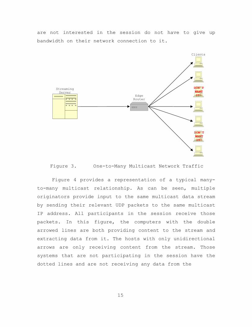
Figure 3. One-to-Many Multicast Network Traffic
Figure 4 provides a representation of a typical many-
to-many multicast relationship. As can be seen, multiple
originators provide input to the same multicast data stream
by sending their relevant UDP packets to the same multicast
IP address. All participants in the session receive those
packets. In this figure, the computers with the double
arrowed lines are both providing content to the stream and
extracting data from it. The hosts with only unidirectional
arrows are only receiving content from the stream. Those
systems that are not participating in the session have the
dotted lines and are not receiving any data from the
Edge Router
Streaming Server
Clients
DON’T WANT IT!
DON’T WANT IT!

16
stream. The latter underscores the fact that not all hosts
on a network will necessarily participate in a given
multicast session.
Figure 4. Many-to-Many Multicast Network Traffic
3. The Multicast IP Address Space
Multicast utilizes a different IP address range than
the address space used for point-to-point (unicast) network
communications. Point-to-point Internet sessions are
conducted using Class A, B, and C IP address ranges. In
contrast, multicast sessions are sent to a group address,
which is part of an assigned Class D IP address space.
This space occupies the range of addresses from 224.0.0.0
to 239.255.255.255. These addresses are also different in
that they are only used on a session-by-session basis
Core Routers

17
while Class A, B, and C addresses are of a more semi-
permanent nature. Figure 5 provides an example of how these
address ranges relate.
Figure 5. IP Address Classes [10]
The multicast address space is maintained by the
Internet Assigned Number Authority (IANA), as are unicast
addresses. The IANA maintains a list of multicast addresses
that have been registered to users or assigned for certain
functions. The 224.0.0.0 to 224.0.0.255 and 239.0.0.0 to
239.255.255.255 address ranges have been set aside for
administrative purposes. The lower address range, 224.0.0.0
to 224.0.0.255, has been permanently assigned to various
applications such as router protocols and subnet
communications. Other permanently assigned multicast IP
addresses are in the range, 224.0.1.0 through 224.0.23.11.
See Table 1 below for a short list of some of the more
notable applications and users. These addresses should not
be used on a session-by-session basis by other users or
functions. The IANA web site (http://www.iana.org)
maintains a complete and up to date list of all reserved
network addresses. [06]
The final entry in Table 1 is the multicast local
scope address range. This address range is to be used for
multicast within a LAN and routers are not supposed to
forward packets addressed to this range outside the LAN.
0 netID hostID01234 8 16 24 31
10 netID hostID
110 netID hostID
1110 multicast addressClass D Class C
Class B
Class A
18
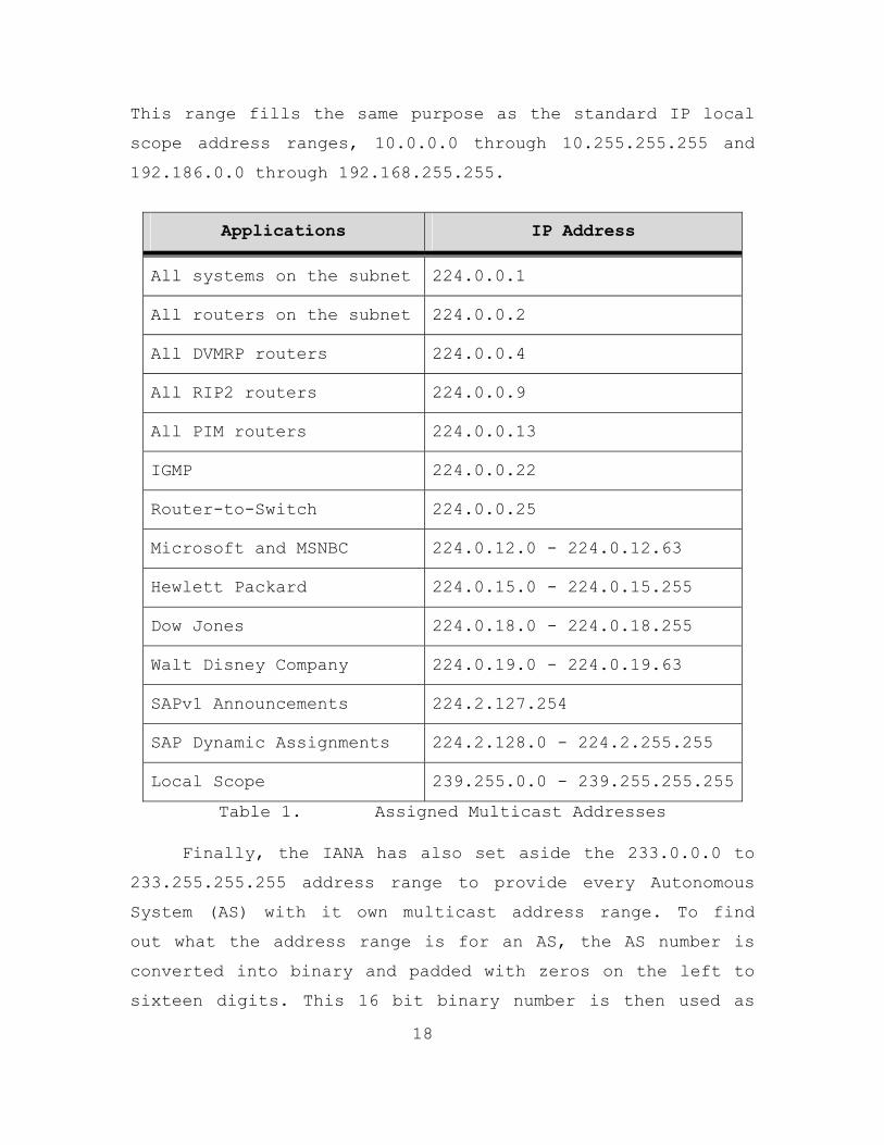
This range fills the same purpose as the standard IP local
scope address ranges, 10.0.0.0 through 10.255.255.255 and
192.186.0.0 through 192.168.255.255.
Applications IP Address
All systems on the subnet 224.0.0.1
All routers on the subnet 224.0.0.2
All DVMRP routers 224.0.0.4
All RIP2 routers 224.0.0.9
All PIM routers 224.0.0.13
IGMP 224.0.0.22
Router-to-Switch 224.0.0.25
Microsoft and MSNBC 224.0.12.0 - 224.0.12.63
Hewlett Packard 224.0.15.0 - 224.0.15.255
Dow Jones 224.0.18.0 - 224.0.18.255
Walt Disney Company 224.0.19.0 - 224.0.19.63
SAPv1 Announcements 224.2.127.254
SAP Dynamic Assignments 224.2.128.0 - 224.2.255.255
Local Scope 239.255.0.0 - 239.255.255.255
Table 1. Assigned Multicast Addresses
Finally, the IANA has also set aside the 233.0.0.0 to
233.255.255.255 address range to provide every Autonomous
System (AS) with it own multicast address range. To find
out what the address range is for an AS, the AS number is
converted into binary and padded with zeros on the left to
sixteen digits. This 16 bit binary number is then used as

19
the middle 16 digits of the binary IP address. Figure 6
depicts this conversion. [07]
Figure 6. AS Multicast IP Address Conversion
The AS number utilized in Figure 6, 257, is assigned
to the Naval Postgraduate School (NPS). Thus, the address
range assigned to NPS for use on the open Internet is
233.1.1.0 to 233.1.1.255. Now that the multicast addressing
schema has been defined a look at the types of multicast is
in order. [08]
4. Types of Multicast
Link-layer and Network-layer Multicast are the two
primary forms of multicast. Network-layer multicast, also
known as IP Multicast, is further broken down into two
classes, Any Source Multicast (ASM) and Source Specific
Multicast (SSM). ASM was the initial type of multicast
developed and is still the primary form of multicast in use
today. Thus, following the discussion in this section, all
references to multicast will signify ASM. All three of
these schemas are expanded on below.
(a) Link-Layer Multicast
Common LAN’s have always been considered a shared
medium for applications utilizing connectionless
0 0 0 0 0 0 0 0 0 0 1 1 1 1 1 1 1 1 1 1 2 2 2 2 2 2 2 2 2 2 3 3 0 1 2 3 4 5 6 7 8 9 0 1 2 3 4 5 6 7 8 9 0 1 2 3 4 5 6 7 8 9 0 1 1 1 1 0 1 0 0 1 0 0 0 0 0 0 0 1 0 0 0 0 0 0 0 1
233 AS Number
257 Local bits
233.1. 1 .000-255

20
communications. This means that all stations on a LAN
listen to all transmissions on the medium. Each of these
stations must have a physical address, which is more
commonly known as a global Medium Access Control (MAC)
address (i.e., unique in the world). [09]
There are three types of MAC addresses; they are
unicast, broadcast, and multicast. Unicast is used for
point-to-point communication between specific hosts or
endpoints on a link. A broadcast MAC address is all 1’s and
is usually not allowed to transcend bridges or routers.
Multicast link layer addresses are used to map stations to
IP-layer multicast addresses. There are a number of Link-
layer multicast solutions that have been utilized. [09]
Frame Relay, Switched Multimegabit Data Service
(SMDS), and Asynchronous Transfer Mode (ATM) multicast are
all examples of link-layer multicast schemes. Frame Relay
multicast was designed to function over Wide Area Network
(WAN) connections between routers. It is connection-
oriented and only its One-way multicast mode has ever had
wide usage. SMDS is connectionless and is functional but
has not gained the popularity of Frame Relay. ATM is
similar to Frame Relay in functionality but at higher data
rates. It is also an emerging technology and its maturity
level is lower. This concludes the discussion on Link-layer
multicast. It is not used as widely as IP multicast and
will not be discussed further in this thesis. [10]
(b) Any Source Multicast (ASM)
Currently, the dominant Network-layer multicast
protocol is Any Source Multicast, also known as Any-to-Any

21
Multicast or Internet Standard Multicast. In this model,
multicast groups are identified by their multicast IP
address. Senders use the multicast group address as the
destination address for packets to that group. This allows
members and non-members, possibly even malicious attackers,
to send data to any multicast group address on a network.
Since ASM allows this many-to-many relationship, it is very
complicated to implement in routers. This ability for every
node in a session to communicate with every other node
comes at great cost to the router. The router must expend
memory and processing power to maintain a dynamic routing
table, where entries must be added and removed as nodes
come and go in the session. Furthermore, the router must
expend the processing power required to duplicate every
packet transmitted for every node, weather they be the next
hope router or switch or the end host, while ensuring that
packets are not transmitted back to the originating node.
This could quickly become a big problem if the number of
participants in a session becomes very large. [11]
Fortunately, most routers purchased within the
last several years come with multicast routing as a
feature, although implementations vary from manufacturer to
manufacturer. This variation can cause configuration and
compatibility problems between routers, as well as
switches, from different manufactures.
(c) Source Specific Multicast (SSM)
The Source Specific Multicast (SSM) protocol is
also a Network-layer multicast type. It is a more recent
development, designed to be more easily implemented in
22
routers and to require less router resources to maintain.
Further, it is touted to scale better than ASM.
SSM provides multicast channels, which are
identified by a group address as the destination in
addition to the source address of the sender or senders. In
this multicast model, only a few pre-specified nodes in a
session are allowed to add content to the session. All
other nodes in the session just receive the data stream.
Traffic is only forwarded to receivers from those multicast
sources with which the receivers have explicitly expressed
interest. SSM is primarily targeted at one-to-many
(broadcast style) or few-to-many applications. Further, SSM
solves many problems that currently exist with the ASM
model, like denial of service attacks and address
allocation. [23]
This concludes the discussion on the different
types of multicast. From this point on, every reference to
multicast will mean ASM. Now, a look at how multicast and
distributed learning can be combined to produce an optimal
leaning environment.
C. MULTICAST DISTRIBUTED LEARNING
Distributed learning and multicast are an excellent
pairing. With multicast’s ability to reach multiple end-
users with minimal network bandwidth utilization and
distributed learning’s goal to train and educate
geographically separated student populations, they
complement one another quite well. Thus, by applying
distributed learning over a computer network utilizing a

23
multicast protocol, a Multicast Distributed Learning (MDL)
capability is established.
MDL has the potential to be the classroom of the
future, incorporating all of the benefits of both the
traditional classroom and distance and distributed learning
courses. It follows that multicast distributed learning has
the potential to become very important in all facets of
society. It remains to be shown whether or not current
networks support it.
The following chapters will examine multicast routing
algorithms, with an emphasis placed on those protocols
utilized at NPS network. Following that, the step-by-step
processes used to assess this network’s ability to support
and sustain multicast are presented. The data obtained
during these tests helped to shed light on the requirements
needed to implement multicast on both current and future
networks in order to support multicast distance learning
throughout the DoD.

24
THIS PAGE INTENTIONALLY LEFT BLANK

25
III. MULTICAST ROUTING PROTOCOLS USED ON NPS NETWORK
There are a multitude of different approaches to
multicast routing and the protocols supporting them are
often incompatible with each other. This is one reason the
implementation of multicast routing in a network is
complex. Router and switch manufactures have a tendency to
implement the same standard protocols in different ways,
adding proprietary components, which causes
interoperability issues with equipment from other
manufacturers. This is the difference between a
manufacturer supporting a standard rather than complying
with it. These inconsistencies then require translation
processing steps or additional hardware or software to
mitigate. They even have the potential to dramatically
impact a network’s efficiency and the QoS provided.
This chapter examines the multicast routing protocols
used at NPS and others that provide useful background
information. It is provided in order to promote a good
understanding of the current multicast routing protocol
versions and the standards upon which they are built. At
this point a critical note must be emphasized: these
protocols are only used to setup the routes from host-to-
router, router-to-host, and router-to-router for the
multicast groups. The actual data stream is sent in the
form of UDP/IP packets. To emphasize this point the
following example is provided.
26
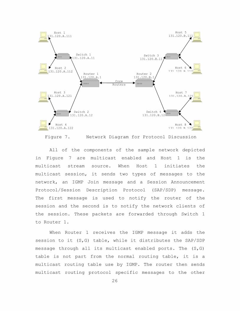
Figure 7. Network Diagram for Protocol Discussion
All of the components of the sample network depicted
in Figure 7 are multicast enabled and Host 1 is the
multicast stream source. When Host 1 initiates the
multicast session, it sends two types of messages to the
network, an IGMP Join message and a Session Announcement
Protocol/Session Description Protocol (SAP/SDP) message.
The first message is used to notify the router of the
session and the second is to notify the network clients of
the session. These packets are forwarded through Switch 1
to Router 1.
When Router 1 receives the IGMP message it adds the
session to it (S,G) table, while it distributes the SAP/SDP
message through all its multicast enabled ports. The (S,G)
table is not part from the normal routing table, it is a
multicast routing table use by IGMP. The router then sends
multicast routing protocol specific messages to the other
Core Routers
Router 1 131.120.A.1
Router 2 131.120.B.1
Switch 1 131.120.A.11
Switch 3 131.120.B.11
Switch 4 131.120.B.12
Switch 2 131.120.A.12
Host 4 131.120.A.122
Host 3 131.120.A.121
Host 2 131.120.A.112
Host 1 131.120.A.111
Host 5 131.120.B.111
Host 6 131.120.B.112
Host 7 131.120.B.121
Host 8 131.120.B.122
27
routers in the network so that the group can be added to
their tables, and it also sends IGMP queries to its hosts
to determine membership preferences.
During this process Host 1 starts transmitting its
UDP/IP data stream to the group and continues to send IGMP
Group Membership messages to Router 1. All of these packets
flow through Switch 1 and it is looking for the IGMP
packets using IGMP Snooping. When it detects these IGMP
packets on one of its port, it sets that port as a
multicast recipient and sends all multicast related packets
to that port as long as IGMP messages come from it.
Other hosts that desire group membership will also
start by sending IGMP join messages to their multicast
enabled router. This in turn will enable their switch ports
to receive the multicast transmission and when the
responsible routers see the join requests, they add their
requesting hosts to their (S,G) table and start relaying
the UDP/IP packet to them. The switches in the network will
utilize IGMP Snooping to minimize multicast traffic on
ports that do not join the session. Each of the protocols
mentioned here will be described in greater detail below.
A. ANNOUNCEMENT AND DESCRIPTION PROTOCOLS
A multicast source uses a SAP/SDP message to announce
and describe a multicast session to the network. The
session source sends a SAP/SDP message when the session is
started and then periodically to keep session information
current (i.e., session modification or deletion).
Announcement repetition also serves to notify dynamic hosts
of the ongoing session.

28
1. Session Announcement Protocol (SAP)
SAP was designed as a means to publicize and
distribute relevant setup-information about multicast
sessions to a prospective audience. It also allows for
session modification and deletion. SAP messages are
distributed using a designated multicast address range that
is not the same as the multicast session addresses it is
publicizing. Furthermore, the SAP requirement does not
contain a rendezvous mechanism and allows for no
reliability above that offered by standard best-effort
UDP/IP. This means that a SAP announcer will never be aware
of the absence or presents of any listener (i.e., the
source of the multicast traffic does not know if there are
any clients for that traffic). In the context of the
example above, while Host 1 periodically sends out SAP
messages to keep the network informed of the session it is
providing, the other hosts in the network join the session
group but do not respond to the source of the SAP messages.
Thus, Host 1 never knows who, if any, of the other hosts in
the network are members of the session. [12]
Another feature of the SAP message is the SDP and
authentication header. The SDP is carried in the payload
segment of the SAP packet, see Figure 7 below. It will be
described in greater detail in the next section. SAP
authentication is not mandatory but can be used to prevent
unapproved session modifications and deletions. The
authentication header is provided for this purpose. See
Figure 7 below for the layout of the header. The
authentication data field is the primary security piece of
the header. It is used by session clients to verify a
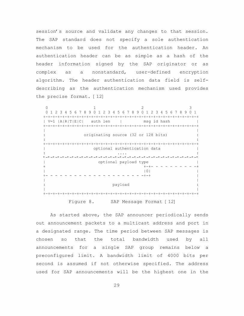
29
session’s source and validate any changes to that session.
The SAP standard does not specify a sole authentication
mechanism to be used for the authentication header. An
authentication header can be as simple as a hash of the
header information signed by the SAP originator or as
complex as a nonstandard, user-defined encryption
algorithm. The header authentication data field is self-
describing as the authentication mechanism used provides
the precise format. [12]
Figure 8. SAP Message Format [12]
As started above, the SAP announcer periodically sends
out announcement packets to a multicast address and port in
a designated range. The time period between SAP messages is
chosen so that the total bandwidth used by all
announcements for a single SAP group remains below a
preconfigured limit. A bandwidth limit of 4000 bits per
second is assumed if not otherwise specified. The address
used for SAP announcements will be the highest one in the
0 1 2 3 0 1 2 3 4 5 6 7 8 9 0 1 2 3 4 5 6 7 8 9 0 1 2 3 4 5 6 7 8 9 0 1 +-+-+-+-+-+-+-+-+-+-+-+-+-+-+-+-+-+-+-+-+-+-+-+-+-+-+-+-+-+-+-+-+ | V=1 |A|R|T|E|C| auth len | msg id hash | +-+-+-+-+-+-+-+-+-+-+-+-+-+-+-+-+-+-+-+-+-+-+-+-+-+-+-+-+-+-+-+-+ | | : originating source (32 or 128 bits) : : : +-+-+-+-+-+-+-+-+-+-+-+-+-+-+-+-+-+-+-+-+-+-+-+-+-+-+-+-+-+-+-+-+ | optional authentication data | : .... : *-*-*-*-*-*-*-*-*-*-*-*-*-*-*-*-*-*-*-*-*-*-*-*-*-*-*-*-*-*-*-*-* | optional payload type | + +-+- - - - - - - - - -+ | |0| | +- - - - - - - - - - - - - - - - - - - - -+-+ | | | : payload : | | +-+-+-+-+-+-+-+-+-+-+-+-+-+-+-+-+-+-+-+-+-+-+-+-+-+-+-+-+-+-+-+-+

30
multicast address scope selected. For instance, since NPS
has the address range from 233.1.1.0 to 233.1.1.255, SAP
messages should be sent to 233.1.1.255 on port 9875. This
is the designated port number for SAP communications and
all SAP messages should be sent to that port. The
information contained in this section was taken from RFC-
2974; see reference [12] for a more in-depth explanation of
SAP.
2. Session Description Protocol (SDP)
Session directory assist applications help in the
advertisement of multicast sessions and communicate the
relevant conference setup information to prospective
participants. SDP was designed as a conveyance for this
information. This protocol does not incorporate a
transport protocol. It was designed to be used as an add-on
to other transport protocols such as SAP. In Figure 7
above, the SDP message in contained in the payload section
on the packet. [13]
SDP provides the following basic information:
• Session name and purpose
• Time(s) the session is active
• The media comprising the session
• Configuration information to receive those media (addresses, ports, formats and so on)
This basic information is only a very small portion of
the information that this protocol can convey. Each of
these fields breaks down into many other fields so that a
session can be described in great detail. All of the

31
information contained in this section was taken from RFC-
2327; see reference [13] if a more detailed explanation of
SDP is needed.
B. INTERNET GROUP MANAGEMENT PROTOCOL (IGMP)
IGMP is one of the primary LAN multicast routing
protocols and version 2 is currently being utilized at NPS.
It is a LAN-based signaling protocol used for the creation
of transient multicast groups, the addition and deletion of
members of those groups, and the periodic confirmation of
group membership. In other words, its primary purpose is
for end-systems (hosts) to declare their membership in a
particular multicast group to the nearest multicast enabled
router. IGMP can also be used for router to router
multicast routing but it is not intended for that purpose
and will not be discussed here.
The original version of IGMP (IGMPv0) was developed by
a Stanford University graduate student, Mr. Steve Deering.
It was first presented in July 1986 as Appendix I of RFC-
988. This asymmetric protocol is similar to ICMP in that it
must be an integral part of IP for multicast to function.
So, for IGMP to work in full on a LAN segment the following
two statements must be true. First, IGMP is required to be
implemented in total by all hosts, conforming to level 2 of
the IP multicasting specification. Second, that LAN segment
needs to have one elected controller, a router, which
periodically queries all hosts. This is the definition of
an IGMP multicast enabled LAN. [14]
When multicast sessions are available on a LAN, the
multicast routers send out IGMP queries intended to refresh

32
their group membership tables or (S,G) table (S = source
address and G = group address), and to allow new members to
join the groups. This is accomplished when the stations
respond to the queries with a report for each group to
which they want to belong. Now, since IGMP query and report
messages are encapsulated in IP datagrams, with an IP
protocol number of 2, the TTL fields on both queries and
reports, for these exchanges, are set to 1. This limits the
scope of the exchange to the local subnet. In Figure 8
below, IGMP will function only between the hosts (i.e.,
131.120.A.###) and their router (i.e., 131.120.A.1). This
figure will be used to facilitate discussion throughout the
remainder of the IGMP section. [14]
Figure 9. Network Diagram for IGMP Discussion
There are currently four versions of IGMP. The
remainder of this section provides summaries of the
relevant IGMP versions and of IGMP Snooping. Since IGMPv0
Router 1 131.120.A.1
Switch 1 131.120.A.11
Switch 2 131.120.A.12
The rest of a Network or the
Internet
Host 4 131.120.A.122
Host 3 131.120.A.121
Host 2 131.120.A.112
Host 1 131.120.A.111
33
is no longer in use, it will not be discussed here. If more
information on IGMPv0 is desired, refer to RFC-988.
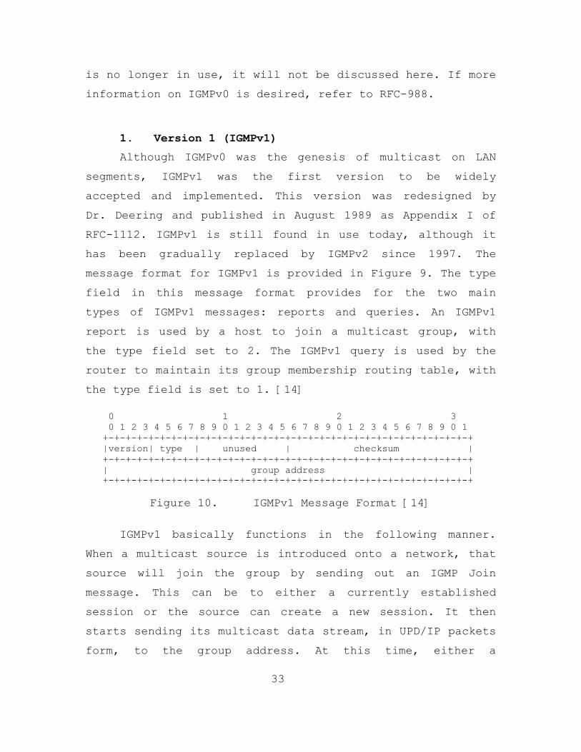
1. Version 1 (IGMPv1)
Although IGMPv0 was the genesis of multicast on LAN
segments, IGMPv1 was the first version to be widely
accepted and implemented. This version was redesigned by
Dr. Deering and published in August 1989 as Appendix I of
RFC-1112. IGMPv1 is still found in use today, although it
has been gradually replaced by IGMPv2 since 1997. The
message format for IGMPv1 is provided in Figure 9. The type
field in this message format provides for the two main
types of IGMPv1 messages: reports and queries. An IGMPv1
report is used by a host to join a multicast group, with
the type field set to 2. The IGMPv1 query is used by the
router to maintain its group membership routing table, with
the type field is set to 1. [14]
Figure 10. IGMPv1 Message Format [14]
IGMPv1 basically functions in the following manner.
When a multicast source is introduced onto a network, that
source will join the group by sending out an IGMP Join
message. This can be to either a currently established
session or the source can create a new session. It then
starts sending its multicast data stream, in UPD/IP packets
form, to the group address. At this time, either a
0 1 2 3 0 1 2 3 4 5 6 7 8 9 0 1 2 3 4 5 6 7 8 9 0 1 2 3 4 5 6 7 8 9 0 1 +-+-+-+-+-+-+-+-+-+-+-+-+-+-+-+-+-+-+-+-+-+-+-+-+-+-+-+-+-+-+-+-+ |version| type | unused | checksum | +-+-+-+-+-+-+-+-+-+-+-+-+-+-+-+-+-+-+-+-+-+-+-+-+-+-+-+-+-+-+-+-+ | group address | +-+-+-+-+-+-+-+-+-+-+-+-+-+-+-+-+-+-+-+-+-+-+-+-+-+-+-+-+-+-+-+-+

34
designated multicast router or the IGMP enabled router
closest to the source will become the querying router. This
router adds the entry to its (S,G) table and sends out an
IGMPv1 query to see if any other hosts want to be part of
the group. It will also periodically send out IGMP queries
to update group membership and maintain its (S,G) routing
table.
If there are multiple hosts on a subnet, when the
router sends a periodic query for group membership to that
subnet each host sets a random countdown timer. Each host
will then listen for a reply on their subnet. The host
whose random timer runs out first will send the IGMP reply.
The other hosts, seeing this reply, will cancel their
impending reply. This reduces the overhead generated by the
routing protocol. If a more detailed description of the
IGMPv1 message format is desired, see RFC-1112. [14]
Using Figure 8 above, the following example is offered
to make the concept more concrete. Host 1 is the multicast
source. It begins the transmission with an IGMPv1 report to
the group address, 233.1.1.100, and starts the multicast
stream to that address. Switch 1 forwards the packets to
Router 1. Router 1 recognizes the IGMP report and, with the
other routers on the LAN, utilizes a manufacturer specific
election process that determines the multicast controller
for the network segment. All the routers add the multicast
group to their routing tables. The controller, Router 1,
then sends out a group membership query to all the hosts on
the network. Host 3 then joins the group by sending an IGMP
report to the group address. Router 1 receives this report,
adds the host to its group routing table, and starts

35
relaying the packet stream from Host 1 to Host 3. This
exchange occurs for every host on a previously pruned port
that joins the group. Periodically, the router will send
the IGMP query to update its table. If Host 3 is the only
member of the group and it fails to send an IGMP report in
response to the periodic queries the router will assume no
hosts desire group membership and will stop the data stream
to that connection. The controller will continue to send
the periodic IGMP queries to all the LAN hosts.
In summary, IGMPv1 provides for a host to join a group
by sending an IGMP report message. To leave a group a host
does nothing; it simply ignores the controller’s queries.
The IGMPv1 router will periodically poll all the hosts on
its subnets using IGMP queries. Hosts on that subnet
respond to the Queries in a randomized fashion to maintain
membership in desired groups. See Appendix I of reference
[14] for a more details explanation of IGMPv1.
2. Version 2 (IGMPv2)
IGMPv2 is currently the backbone of LAN segment
multicast routing. It was defined by W. Fenner in RFC-2236,
which was accepted by the IETF in November 1997. This
action made IGMPv1 obsolete and brought IGMPv2 to the
forefront of the multicast effort. This version of IGMP is
backwards compatible with IGMPv1 and is, for the most part,
just an enhancement to it. The primary improvement over
IGMPv1 is the addition of a multicast controller election
process, Leave Group messages, and Group Specific queries.
These augmentations were predominantly made to improve the
performance of the protocol. [15]

36
Figure 11. IGMPv2 Message Format [15]
Figure 10 is the message format for IGMPv2. In
comparing this format with that of IGMPv1 note that the
Version and Type fields are combined into a single Type
field. Also note that the second field, previously unused,
now contains the Maximum Response Time field. These changes
where made so that routers on WANs where both IGMP versions
are use can tell the difference between an IGMPv1 and
IGMPv2 host report. Furthermore, new IGMP types have been
assigned to the Version 2 Membership Report messages and
the Leave Group message. A Leave Group message is used by a
host who no longer wishes to be part of the multicast
session. Now, instead of ignoring the router queries and
waiting to be dropped from the group, the host sends a
Leave Group message to the router and the router
immediately removes the host from the session.
In IGMPv1, the controller election process was not
part of the specification and thus, various implementations
of the IGMPv1 had different mechanisms to perform the query
function. This had the potential to result in more than one
controller per network. IGMPv2 incorporated the election
mechanism and made it part of the standard. In networks
where IGMPv2 routers coexist with IGMPv1 routers, the
potential problem of multiple controllers still exists. To
mitigate this problem, an IGMPv2 router must be able to act
0 1 2 3 0 1 2 3 4 5 6 7 8 9 0 1 2 3 4 5 6 7 8 9 0 1 2 3 4 5 6 7 8 9 0 1 +-+-+-+-+-+-+-+-+-+-+-+-+-+-+-+-+-+-+-+-+-+-+-+-+-+-+-+-+-+-+-+-+ | type | max resp time | checksum | +-+-+-+-+-+-+-+-+-+-+-+-+-+-+-+-+-+-+-+-+-+-+-+-+-+-+-+-+-+-+-+-+ | group address | +-+-+-+-+-+-+-+-+-+-+-+-+-+-+-+-+-+-+-+-+-+-+-+-+-+-+-+-+-+-+-+-+

37
like an IGMPv1 router. To do this it utilizes the Version 1
type-field values, sets the Max Response Time field to 0
for all queries, and ignoring Leave Group messages.
If the network in Figure 8 employs Version2 and Host 1
is again the multicast source, Host 1 initiates the
multicast session by sending an IGMPv2 report to the group
address, again, 233.1.1.100, and starts transmitting the
multicast stream to that address. Switch 1 forwards the
packets to Router 1. Router 1 recognizes the IGMP report
and, with the other routers on the LAN, utilizes the
standard election process to determine the multicast
controller for that network segment. All the participating
routers add the multicast group to their (S,G) routing
tables. The controller, Router 1, then sends out a group
membership query to all the hosts on the network. Host 3
joins the group by sending an IGMP report to the group
address in response. Router 1 receives this report, adds
Host 3 to its (S,G) routing table, and starts relaying the
packet stream from Host 1 to Host 3. The router will resend
the IGMP query to update its table. To stop receiving the
multicast stream, Host 3 sends a Leave Group report to the
group address. When the controller receives this report it
sends a group specific query to that port to check for any
remaining members. If no reports are received it
immediately removes that host from its (S,G) table and
stops the data stream to that port since there are no
longer any hosts desiring membership. It is key to remember
that the (S,G) table is comprised of entries that specify
the Source (i.e., host or subnet connected to that port on
the router) and the Group to which it belongs. So, if a
Source belongs to several multicast Groups, then each will
38
have an entry in the (S,G) table. The controller will
continue to send the periodic IGMP queries throughout the
LAN even though that branch has been pruned.
In summary, IGPMv2 is backwards compatible with
IGMPv1. The primary differences being the addition of a
standardized multicast controller election process, the
Leave Group messages, and Group Specific queries. See
Appendix I of reference [15] for more details of IGMPv2.
3. Version 3 (IGMPv3)
IGMPv3 was developed by the IETF Network Working Group
and accepted as RFC-3376 in October of 2002. Since this
protocol has been in use for such a short time, with only
limited implementations thus far, only a brief summary will
be provided here. The main additional feature of IGMPv3 is
the inclusion of source filtering. This change allows
IGMPv3 to accommodate SSM as well as ASM. This change was
accomplished by modifying the format of membership reports
and queries. The query message size has been increased and
the ability to designate multiple specific sources for a
particular group has been added. For Ethernet networks, the
number of multicast sources that can be specified in a
given query is limited to 366. This constraint is due to
the maximum transfer unit (MTU) size. Membership report
messages now have there own format which allows a host to
join a group and specify a set of sources from that group
from which it will receive data streams. The new format
also has multiple sections to report membership in multiple
groups, thus allowing report of a host’s full current state

39
using fewer packets. Similarly, leave group messages have
been enhanced to allow combined group source leave
messages. [16]
Further enhancements were also included. Version 3
maintains the state as Group-plus-List-of-Sources and the
IP Service Interface was changed to allow specification of
source-lists. The controller includes its Robustness
Variable and Query Interval in Query packets to allow
synchronization of these variables on non-controller
routers. The Maximum Response Time in Query messages has an
exponential range, changing the maximum from 25.5 seconds
to about 53 minutes, which helps when used on links with
huge numbers of systems spread over a large area. Hosts
retransmit state-change messages to increase robustness.
Join Group messages and Leave Group messages are both
considered state-change messages because they change the
state of that port on the router. Additional data sections
are defined in the message formats to allow later
extensions. Report packets are sent to 224.0.0.22, this
assists layer-2 switches with IGMP snooping. Hosts no
longer perform report suppression, to simplify
implementations and permit explicit membership tracking.
Finally, the new “Suppress Router-Side Processing” flag in
query messages fixes the robustness issues which are
present in IGMPv2. [16]
IGMPv3 is backwards compatible with both IGMPv1 and
IGMPv2 systems and interoperability with these systems is
defined as operations on the IGMPv3 state diagram. This is
accomplished in much the same manner as in IGMPv2, in that
40
the IGMPv3 router basically emulates an older router when
placed on networks in which older routers still operate.
[16]
In summary, IGPMv3 adds Group-Source Specific Queries,
Reports, and Leaves messages to IGMPv2. It also adds
Inclusion and Exclusion of sources. For a more in-depth
description of the protocol refer to [16].
4. IGMP Snooping
An Ethernet switch floods multicast traffic within the
broadcast domain by default and this can consume a lot of
bandwidth if many multicast servers are sending streams to
the segment. Multicast traffic is flooded because a switch
usually learns MAC addresses by looking into the source
address field of all the frames it receives. But, since a
multicast group destination MAC address (i.e.,
01:00:5E:XX:XX:XX) is never used as a source MAC address
for a packet and since they do not appear in the MAC
Filtering Database, the switch has no method for learning
them. [17]
In switched LAN environments multicast flooding can be
a major problem. A technique known as IGMP Snooping is
used to reduce this effect. Essentially, this routing
method turns on and off multicasting to switch ports, at
layer 2, by promiscuously monitoring each port for IGMP
traffic. On switch ports where IGMP traffic is found, IP
multicast traffic is forwarded. This greatly reduces the
impact of flooding by layer 2 switches and decreases the
potential congestion that can lead to frame loss. [17]
41
IGMP was not designed to determine routing paths
between LANs in a WAN topology (i.e.: router-to-router). It
has to much overhead to work effectively on a large scale.
This is an area where multicast routing protocols need to
be efficient and are very important. The following section
address the first protocol designed for this purpose. [17]
C. DISTANCE VECTOR MULTICASTING ROUTING PROTOCOL (DVMRP)
While the IGMP protocol is used to setup paths from
router-to-host in the routing table of the multicast-
enabled “designated router” (DR), DVMRP is used for router-
to-router path discovery. It was described in RFC-1075 and
was the first multicast routing protocol designed for this
purpose. Most of the information in this section was taken
from RFC-1075. While DVMRP is not used at NPS, it was the
preeminent multicast routing protocol until 1997 and is the
second most used one today. [18]
DVMRP was loosely based on the Routing Information
Protocol, Version 2 (RIPv2) and uses a distance vector
technique based on the Bellman-Ford routing algorithm. This
protocol uses the concept of next-best-hop and does not
maintain a total picture of the router mesh inside each DR.
Furthermore, DVMRP and RIP both have the same 32 hops
maximum router mesh width. This restriction limits the
deployment to small and medium sized enterprises. The
Internet cannot universally use DVMRP for this reason. In
addition, DVMRP only uses the hop count metric in its best
route determination, which means that metrics such as link
cost and congestion are ignored. [05]

42
Another thing that makes DVMRP similar to RIPv2 is its
support for classless IP addresses. In this approach, the
subnet mask is sent along with the IP address. This is
referred to as Variable Length Subnet Masking (VLSM) and is
a characteristic trait of RIPv2. [19]
DVMRP does not use the IP unicast routing table in the
router. It uses a separate Multicast Routing Table (MRT)
and a Multicast Forwarding Table (MFT) for all multicast
traffic. The MRT is used to store routes back to a given
multicast source. Notice the use of multicast “source” here
instead of “destination” as would be in the case of RIPv2.
This is due to the fact that IP-Multicast looks at the
spanning tree in reverse. All multicast packets traverse
the tree backwards from the end-users back to the source,
rather than source to end-users as is done in conventional
routing. Since a multicast group address references a group
of nodes instead of a specific node, this is the only way
that routing makes sense in a multicast world. [05]
The MFT is a simple vector of (S,G) values with their
associated incoming interface port, outgoing interface
port(s) and prune status. It is used by the routers’
routing logic to quickly forward multicast packets to the
correct outgoing interface based on the source and group
addresses. It must be noted that the prune status, which is
discussed below, is included so that traffic is not
forwarded out branches that have requested not to be part
of the active tree for that group. [05]
A series of floods, prunes, and grafts are used to
build a multicast spanning tree. In DVMRP, the term flood
refers to a process in which all DVMRP multicast routers

43
transmit multicast packets to all outgoing interfaces.
DVMRP’s insistence on doing this is a bit extreme, since
many of the DVMRP routers may not have end-user nodes that
are interested in joining the group (i.e., their (S,G)
tables, filled-in by IGMP, are empty). In these cases, the
routers in question will send “prune” messages to the DR.
This is also referred to a sending prune messages back "up
the tree", or “upstream”. These prune messages tell the DR
that they are not interested in the multicast traffic and
the DR then stops forwarding them to that router. But the
effect of the pruning is only temporary, after a couple of
minutes the pruned branches re-grow, offering every router
another chance to either re-join the main tree, if a host
has requested entry into the multicast group via IGMP, or
to send another prune message. [19]
The last message in DVMRP to examine is the “graft”
message. It is used when a router is ready to re-enter the
tree immediately, without waiting for the “de-pruning”
process. The router in question sends a graft message
upstream and the DR immediately grafts that branch back
onto the tree. In current implementations of DVMRP, the DR
maintains all information on pruned branches in its MFT and
never really deletes them. The high volume of prune, grow-
back, and graft operations in a typical multicast network
make deleting impractical. Just toggling the state field in
the MFT for each entry saves the router CPU cycles. This,
and the modest amount of memory required to track all
branches is insignificant compared to what it would take to
just do the delete and add processes in a dynamic network.
[19]
44
The network tree structure that is created through the
process above is called either a shortest path tree (SPT),
a “dense mode source distribution tree”, or a “truncated
broadcast tree” in IP-Multicast literature. Here the term
“dense mode” is very applicable since it refers to the fact
that, in this protocol, multicast traffic deliberately
penetrates most of the overall network and that this is a
desirable effect. Of the three terms above, SPT is the one
most commonly used. [05]
A DVMRP router learns about its adjacent neighbors by
sending periodic “Hello” messages on all of its outgoing
interface ports. This action is performed on the 224.0.0.4
multicast address. As shown in Table 1, this is the “All
DVMRP Router” address used by DVMRP routers. When a Hello
message is received, the DVMRP router checks to see if its
address is in the “Neighbor List” field of the message. If
not, it places the interface address of the sending router
in its Hello message and sends it. When a router receives
the "Hello" message from the same router and identifies its
own interface address in the messages Neighbor List field,
the router knows that a two-way multicast routing
connection has been successfully formed between itself and
the message source. [19]
A typical DVMRP MRT has the following entries: source
network, source network subnet mask, administrative
distance, number-of-hops metric, uptime, expiration timer,
next hop address and interface going towards the source,
and information about the neighbor that sent the DVMRP
route message. Periodically, each router transmits its
entire multicast routing table to all of its DVMRP
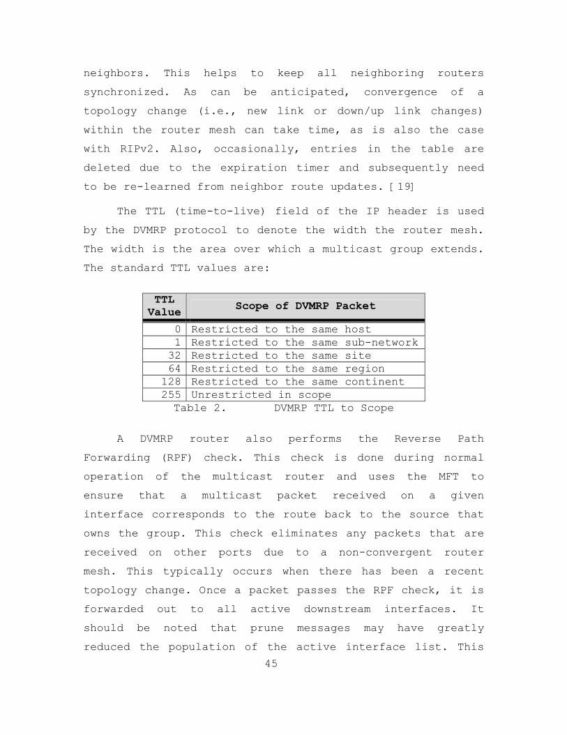
45
neighbors. This helps to keep all neighboring routers
synchronized. As can be anticipated, convergence of a
topology change (i.e., new link or down/up link changes)
within the router mesh can take time, as is also the case
with RIPv2. Also, occasionally, entries in the table are
deleted due to the expiration timer and subsequently need
to be re-learned from neighbor route updates. [19]
The TTL (time-to-live) field of the IP header is used
by the DVMRP protocol to denote the width the router mesh.
The width is the area over which a multicast group extends.
The standard TTL values are:
TTL Value Scope of DVMRP Packet
0 Restricted to the same host 1 Restricted to the same sub-network 32 Restricted to the same site 64 Restricted to the same region
128 Restricted to the same continent 255 Unrestricted in scope Table 2. DVMRP TTL to Scope
A DVMRP router also performs the Reverse Path
Forwarding (RPF) check. This check is done during normal
operation of the multicast router and uses the MFT to
ensure that a multicast packet received on a given
interface corresponds to the route back to the source that
owns the group. This check eliminates any packets that are
received on other ports due to a non-convergent router
mesh. This typically occurs when there has been a recent
topology change. Once a packet passes the RPF check, it is
forwarded out to all active downstream interfaces. It
should be noted that prune messages may have greatly
reduced the population of the active interface list. This

46
reduction is crucial in a dense mode protocol because
without pruning multicast looks more like IP broadcasting
until the final-hop, where IGMP handles the final packet
delivery. [19]
As was previously noted, DVMRP does not scale well and
tends to be quit verbose. In addition, DVMRP requires lots
of router memory to maintain the separate multicast routing
and forwarding tables. This protocol is, however, the
easiest multicast routing protocol to understand and is
viable for small-to-medium size networks. This is
especially true if only LANs are involved and most end-
users want to receive the majority of the transmitted
multicast traffic. Finally, the DVMRP SPT approach, which
uses a designated rendezvous point router, is in direct
contrast to protocols that use the “shared tree” approach
that is not based on the multicast source's router. PIM-SM
uses this shared tree approach. [19]
D. PROTOCOL INDEPENDENT MULTICASTING (PIM)
The IETF’s Inter-Domain Multicast Routing (IDRM)
working group began development of a multicast routing
protocol that would operate independent of the unicast
routing protocol being used. One of the primary goals of
this group’s effort was to develop a protocol that can use
existing routing and topology tables, and does not create
multicast specific tables. This approach is in direct
contrast to DVMRP and its use of the MRT and MFT. [05]
While the PIM protocol was designed to provide
superior sparse mode operation, it supports a dense mode
model as well. The decision by the committee to provide

47
both modes allows PIM to be a total solution for IP-
Multicast without depending on DVMRP or other protocols for
a dense mode solution. These modes, sparse and dense,
operate quit differently and are discussed in detail in the
next two subsections. [05]
1. Sparse Mode (PIM-SM)
Currently, the most popular IP-Multicast protocol is
PIM-SM. [18] When the PIM protocol for IP-Multicasting is
mentioned in multicast literature it is usually in
reference to the sparse mode of its operation. PIM-SM is
one of only a small number of IP-Multicast approaches that
provides a more efficient method for multicasting when
there is only a small number of end-users that want to
receive the group traffic or when a WAN link is needed to
access the multicast sources. PIM-SM uses a Rendezvous
Point Tree (RPT) as its primary spanning tree. This means
that a single “rendezvous” point (RP) is between sources
and recipients. A multicast-enabled router specified by the
network administrator functions as the RP and is typically
the first-hop router from the multicast sources. Since the
end-users are downstream from the RP-based distribution
tree, the designation for a particular multicast group is
(*,G). This implies that all multicast groups are sourced
from the same RP. In reality, the existence of multiple RPs
in a network is possible, each responsible for a subset of
the multicast group addresses on that network. [05]
In order to make this shared tree approach work for
multicast, some initial difficulties had to overcome. Since
an RPT is unidirectional and packets can only flow from the

48
RP to the end-user, a discovery mechanism for RPs and other
downstream routers was needed to enable new group users to
be added. Furthermore, a means of providing a given last-
hop router with the initial IP address of the RP needed to
be established. [05]
The process used to discover a new group user involves
sending a standard SPT from the last-hop router back to the
RP. The router’s standard unicast routing table is used and
a “PIM Shared Tree Join” is performed. When this occurs,
each router along the path back to the RP adds the (*,G)
entry for the required multicast group. Remember, end-users
will join a group using the standard IGMP protocol
discussed above. When a last-hop router, using IGMP
discovers that there are no subscribers to a given
multicast group, a “Shared Tree Prune” message is sent back
up the SPT to the RP so that it can stop the packet flow to
that router. Using this technique, timeouts are not the
primary means to prune branches. [05]
Currently, there are several methods used for a given
last-hop router to gain initial knowledge of the RP’s IP
address. The most straightforward approach is to manually
enter the RP's IP address into every router that might
participate in multicast session. The fundamental problem
with this method is its inability to scale. There are
several proprietary methods used to automate this function,
but they are neither widely excepted nor implemented and
will not be discussed here. Version 2 of PIM-SM, which is
currently in IETF draft, (http://www.ietf.org), offers
another option. It outlines a bootstrap process what will
be used to discover the addresses of all RPs on the
49
network. The method used depends on the PIM version
implemented and the network equipment used. But it is
crucial that the multicast routers know the RP's IP
address, since standard unicast routing is used to
implement a group join operation. [05]
PIM-SM has one feature that is not available in other
sparse mode protocols. The ability for a last-hop router to
request a direct SPT back to a multicast source, without
requiring the source to link to the shared RP tree, was
included in the protocol. This feature gives a source node
the ability to provide service directly to a set of end-
users without routing the multicast stream through an RP.
[05]
A final note on the operation of PIM-SM: it uses a SPT
from the RP back to the source so that the source can
provide its packet stream to the RP. The source informs the
RP of its existence by sending a special PIM message,
called a “Source Registration”, directly to the RP's IP
address using a unicast packet. Once the RP receives the
unicast packet, it then makes the reverse connection back
to the sourcing node. This connection is not a standard TCP
connection. It is more along the lines of a UDP message
from the source to the RP and another from the RP to the
source. Once this packet exchange, is made the two devices
are in essence, connected and the source now has the
required routing information. [05]
2. Dense Mode (PIM-DM)
PIM-DM is the core multicast routing protocol used at
NPS. Like DVMRP, PIM-DM is a dense mode multicast protocol
50
using an SPT model. But unlike DVMRP, PIM-DM does not use
the MRT and MFT to determine which interface ports from
which to transmit multicast group packets for a given (S,G)
combination. Its approach to multicast group packet routing
is to blindly transmit multicast packets to all non-pruned
interfaces. The overhead of this additional packet
duplication is accepted in order for the protocol to
operate independently of the IP unicast routing tables and
the network topology. Recall that PIM is “protocol
independent.” This means it is independent of the
underlying unicast routing protocol. A better description
of this might be that it can interoperate with any
underlying unicast routing protocol. Since PIM makes no
assumptions about the underlying routing protocol, its
reverse path forwarding algorithm is slightly simpler,
albeit, slightly less efficient, than the one used in
DVMRP. Additionally, no parent/child databases needs to be
created. From this, it is valid to conclude that PIM-DM is
a good choice for networks in which bandwidth is plentiful,
a large percentage of the end-users require multicast
traffic, and little or no users require WAN links to reach
the multicast sources. [20]
Thus, it appears to be a good fit for NPS as long as
multicasting is used only within the internal network.
However, it could be a problem in the long run, if
multicast is used for distributed learning outside of the
NPS network. This protocol is currently being revised by
the IETF’s Inter-Domain Multicast Routing group and is in
Internet draft form. It was due to be endorsed in August of
2003. To find out more about its current status, go to the
IETF web site (http://www.ietf.org). [20] Now that the

51
basic function of the IP-Multicasting protocol that are
relevant to NPS have been examined, their throughput and
reliability need to be considered.
E. IP MULTICAST PROTOCOL COMPARISON
To determine whether or not an IP-Multicast protocol
is effective, its timing requirements must be considered.
The timing values for a given protocol are a key
determining factor of its performance. It is not only
critical to the IP-Multicast applications that use it but
also to the network hardware that it traverses. Values such
as timer size and timeout values, as well as table
structure and sizing, are critical in judging a protocols
overall performance and how it will integrate into a
network. While selecting a particular protocol for use on a
network is more complex than the simple tradeoff of speed
versus reliability, it must be realized that currently no
single multicast protocol meets all multicast requirements.
[18]
The data in Table 3 below provides detailed timing
information for the IP Multicasting protocols described in
this chapter. It is provide in order to further distinguish
between the protocols:
Protocol Message Timing
SAP/SDP Announcement Every 10 seconds Membership Query Every 60 seconds (Query Interval) Membership Report Random countdown from 0 to 10 seconds IGMPv1 Leave Latency (3*Query Interval)=180 seconds Membership Query Every 125 seconds (Query Interval)
Membership Report
Random countdown based on value specified in Membership Query (.1 increments) with default equal to 100 (10 seconds – as in version 1)
IGMPv2
Controller Election Timeout (2 * Query Interval) = 250 seconds

52
Protocol Message Timing
IGMPv3 Same as for Version 2 Same as for Version 2
Neighbor Discovery Hello Every 30 seconds
Neighbor Adjacency Timeout
(3 * Neighbor Discovery Msg.) = 90 seconds (Nortel uses = 140 seconds)
Multicast Routing Table Update Every 60 seconds (similar to RIP)
Route Expiration Timer 200 seconds
Prune Reset Every 120 seconds
DVMRP Routing Table
Source Subnetwork & Subnet Mask, Incoming Interface, Outgoing Interface(s), Metric (Hop Count), TTL, and Status
DVMRP
DVMRP Forwarding Table
(S,G), TTL, Incoming Interface, Outgoing Interface(s), Prune Status
PIM Hello Message 30 seconds Neighbor Adjacency Timeout (3.5 * PIM Hello Msg.) = 105 seconds
PIM Neighbor Table Entry
Neighbor Address, Interface, Uptime, Expiration Timer, Mode (Dense, Sparse), Designated Router ("DR") Flag
Prune Reset Every 180 seconds
PIM-DM
Prune Delay Timer 3 seconds PIM-SM Forwarding State Entries deleted every 180 seconds
PIM-SM (*, G) Join Refresh Messages Sent upstream every 60 seconds
Table 3. IP-Multicast Protocol Timing [18]
As discussed in the previous two sections, PIM-SM is
the most popular IP-Multicast protocol for an enterprise
network, with DVMRP a distant second, and PIM-DM an even-
further-trailing third. The Multicast Backbone (MBone) is a
multicast network set up in the late 1980’s that was used
primarily for research and educational purposes. It still
extends mainly between educational institutions and
extensively uses DVMRP. However, the MBone is largely a
core Internet infrastructure and most enterprises do not
implement it internally. Recently, an exterior Internet
routing protocol, BGPv4, was extended to provide inter-
Autonomous System multicast routing. It was designated

53
"MBGP" (Multicast BGP) and could give PIM-SM some
competition. This protocol is relatively new and it will
not be discussed further in this thesis. If more
information is needed on this protocol, please go to the
IETF web site (http://www.ietf.org). [18]
F. NETWORK HARDWARE AND MULTICAST
The hardware (i.e., the routers and switches) that
makes up a network are the core technology of that
infrastructure and their ability to handle the requirements
placed on them by the communications protocols is critical
to the QoS that a network provides. If a central router in
a network does not support multicast effectively, then it
not only degrades the network’s ability to provide
multicast support, but could severely degrade traditional
network traffic if multicast traffic is introduced into the
network.
Based on a poll conducted for reference [18], it was
suggested that the number of active IP-Multicast groups,
e.g. (S,G) count in DVMRP and (*,G) count in PIM-SM, be a
minimum of approximately 256 for an organization. That
said, many institutes have a typical active population
closer to 2,000. The maximum number of active groups
observed during the poll, on one corporate network was
nearer to 10,000. It was also noted that military and
defense contractors could require an even higher active
group count than this. [18]
These statistics provide a very important insight into
the importance of network hardware. The maximum number of
active multicast groups that a vendor’s routers and

54
switches can handle is critical in a network which intends
to heavily utilize multicasting. But determining this
maximum number is not a simple task since many protocols,
supporting unicast or multicast traffic, share available
Random Access Memory (RAM) and Content Addressable Memory
(CAM) space. The only thing that is currently clear is that
more router memory allows more sessions. The article in
reference [18] stated that high-end Cisco and Nortel
Networks routers were able to easily manage tens of
thousands of simultaneous multicast groups while
maintaining their QoS. [18]
In this chapter the pertinent multicast routing
protocols used at NPS and the ones used extensively in the
Internet environment were examined. This consisted of an
appraisal and comparison of their properties and
attributes. During this process PIM-DM was found to be the
multicast routing protocol primarily used today.
Furthermore, there relationship to each other was also
reviewed. At this point it should be clear that SAP/SDP,
IGMP, and PIM-DM are supposed to be in use at NPS, but
whether or not that will hold up during testing will be
determine next. The next two chapters detail the tests
performed in the laboratory and on the NPS network in
support of this thesis. These tests were developed by the
author of this thesis in order to determine whether or not
the hardware used in the NPS network was capable of
supporting multicast traffic without reducing the QoS level
provided to all users.

55
IV. LABORATORY TESTING, DATA ANALYSIS, AND RESULTS
Two categories of tests were performed to quantify the
thesis’ hypothesis that the NPS network can sustain the
uses of multicast with little or no effect on the network
current QoS; one in a lab environment and the other over
the school’s live network. The next two chapters describe
the various tests that were performed during the network
analysis phase of this thesis. This chapter describes the
testing done in the laboratory. It provides the reasoning
behind it, how it was done, any problems that were
encountered, what data was collected, how the data was
analyzed, and the results and conclusions drawn from it.
The test plans used for this chapter are located in
Appendix A. It is realized that the information in this
thesis will be outdated within the next year, but it is
hoped that the test examples in this chapter and the next,
along with the test plans in Appendices A and B, will
provide future multicast implementers with a workable
starting point for their effort. This information is also
supplied to promote further exploration in the multicast
research area and as a roadmap for anyone implementing
multicast on a legacy network. In Sections A and B below,
an evaluation of the network analysis applications and
multicast software and equipment that were evaluated for
inclusion in the test suite is provided. In Sections C and
D, the switches and routers used at NPS are evaluated to
ensure proper operation on multicast protocols. These
sections and subsections provide an overview of the test
plan and the motivation behind each test.
56
Laboratory testing was conducted in order to validate
the multicast operation of current NPS network hardware and
to evaluate the software to be utilized during testing
without putting the live network at risk. These tests
provided the author with insight into the operation of the
multicast protocols discussed in Chapter III. It also led
to a determination of the applications that would be used
during the live network tests and to a multicast
configuration for the two types of switches used at NPS.
A. EVALUATION OF MULTICAST APPLICATIONS
Prior to performing any tests in the laboratory, much
less on the NPS production network, an evaluation of the
applications and standalone units being considered for
inclusion in the multicast test tool suit was performed.
This was done in order to ensure that a standard set of
tools was used for every test and to reduce the possibility
of catastrophic network failure. The tools listed below
were evaluated on cost; ease of installation,
configuration, and use; effectiveness; and standard
protocol use. This pre-testing of the tools set reduced the
possibility of introducing errors into the core NPS network
due to a tool behaving in a nonstandard or unexpected
manner. The various data capture and analysis tools and
multicast server and client applications listed below, were
tested and only stable applications with standard
implementations were included in the test tool suit. All
the applications listed below were evaluated using the test
plan in Section A of Appendix A.
57
1. Ethereal
One of the primary tools any network analyst uses is a
network sniffer. A sniffer is made up of a computer with a
network connection that is running software capable of
capturing network traffic packets. Ethereal is an
application that performs this function. It is a free
network protocol analyzer for both UNIX and Windows that
allows the user to capture and examine network packets from
a live network or from a file on disk. Further, it allows
interactive browsing of the captured data, and summary and
detailed information for each packet. Ethereal also has
several powerful features, which include a rich display
filter language and the ability to view the reconstructed
stream of a TCP session. After evaluating this tool against
the criteria in the test plan, it was rated very high for
the following reasons; it is a no cost tool that performs
all of the functions needed to capture and analyze network
traffic; it is easy to install, configure, and use; and it
has the ability to open files created by other capture
applications. Version 0.9.14 of this application was used
throughout all of the tests conducted for this thesis; it
was procured from http://www.ethereal.com.
2. TEthereal
This tool is a text version of Ethereal. It was
considered for use for the same reasons as Ethereal, was
accepted for the same reasons, and was used to complement
Ethereal. Using the batch job feature of this tool allowed
packet captures over a twenty-four hour period in an
unsupervised environment and was a great success. This tool
58
is part of the Ethereal installation, thus it has the same
version number and was procured from the same location.
3. EtherPeek
EtherPeek is a commercial tool from WildPacket, Inc.,
that is much like Ethereal. It was considered for the same
reasons as Ethereal and was included in the tool suite due
to a small amount of use while using NOC equipment. The
primary deterrent to using this tool instead of Ethereal is
its high cost. Due to the limited budget for this project,
it was not a viable candidate. But as stated before, while
testing the NPS network and utilizing NOC equipment, it was
used for some minor packet capturing. The saved files were
then analyzed using Ethereal. Version 2.0.0 of this
application was used while using a NOC laptop; it was
loaded on the laptop when borrowed.
4. SolarWinds Professional Plus Edition
This set of network management tools was developed by
SolarWinds.net. It was evaluated for use in this project
for its ability to monitor the bandwidth usage of every
port on multiple hubs, switches, and routers. It uses the
Simple Network Management Protocol (SNMP) to interface with
the devices and collect data by monitoring both the send
and receive traffic of each target port. It is extremely
easy to install, configure, and use, and provides extensive
network monitoring capability. Further, it provides an easy
means to view and graph the data it collects. This tool set
was also used throughout the tests documented in Sections C
and D, and throughout Chapter V. All of the graphs in the

59
next chapter were created using it. Unfortunately, this
tool is costly which may be a consideration in its adoption
in a typical tool suite. The Bandwidth Monitor application,
Version 5.0.93, was the primary tool out of the set used
during testing. The SolarWinds.net web site
(http://www.solarwinds.net) contains more information on
this tool set.
5. Iperf
This is a free tool, supplied by the National
Laboratory for Applied Network Research (NLANR). This tool
was designed to measure TCP and UDP bandwidth performance
and was considered for inclusion in the multicast test tool
suite for this reason. It is easy to install, configure,
and use. Furthermore, it can be configured to send UDP
traffic to a multicast address and will report bandwidth,
delay jitter, and datagram loss. Unfortunately, it does not
utilize the required multicast routing protocol, IGMP, so
it was not added to the multicast test suite. Without IGMP
to configure the routers to properly relay multicast
traffic, all switches and routers in the network treat the
multicast traffic like broadcasts, sending it to every
active interface. Over the core of a network, this could
flood the network and could cause severe QoS problems.
Version 1.7.0 of this application was tested and it can be
downloaded from http://dast.nlanr.net. More information on
this tool can be found at the Distributed Applications
Support Team web site listed above.

60
6. Multi-Generator Toolset
The Multi-Generator (MGEN) tool set is open source
software created by the Naval Research Laboratory (NRL)
Protocol Engineering Advanced Networking (PROTEAN) Research
Group. It’s free and was considered due to its ability to
perform IP network performance tests and measurements using
UDP/IP traffic. This toolset transmits real-time traffic
onto a network in order to simulate loading and it can also
receive and log traffic for analysis. As with Iperf, the
tool sends a UDP packet stream to a multicast address
without the multicast routing protocol, IGMP. So the hubs,
switches, and routers were flooded with broadcasted
multicast packets. This tool set was not included in the
test suite. Version 4.0 of this application was evaluated;
it can be downloaded from http://manimac.itd.nrl.navy.mil.
See the NRL web site for more information on the tool.
7. Mbone Applications
This is a free suite of applications developed at the
University College of London by its Networked Multimedia
Research Group. It was considered for inclusion in the
multicast test suite due to its ability to send various
types of data streams to multicast groups. It consists of a
Session Directory (SDR) Tool, Robust Audio Tool (RAT),
Videoconferencing (VIC) tool, Whiteboard (WBD) tool, and
Network Text Edit (NTE) tool. All of these applications put
together can provide a total multicast solution for a
networked classroom or discussion group. They utilized the
standard multicast routing protocol, IGMP. Additionally,
the SDR tool uses SAP/SDP messages to relay session
61
information to other host running SDR or applications that
support the SAP/SDP protocol.
Unfortunately, installation and configuration are
difficult and would be beyond the average user. Once
installed, they are relatively easy to use. Each tool must
be downloaded and installed separately. Then modifications
to the systems environmental variables need to be performed
manually for them to work together. Configuring the
multicast address scheme is complex, as each application
listed above utilizes a different address for its service
(i.e., voice, video, whiteboard, text edit). The final
problem is that the output bandwidth was not stable. For
example, every pause when using a microphone to input voice
caused the data stream bandwidth to fluctuate.
For these reasons, this entire tool suite was not
added to the test suite. The SDR tool was included,
however, due to its use of SAP/SDP. SDR was used to check
for sessions produced by the VBrick and VBrick StreamPump.
See the UCL web site at http://www-
mice.cs.ucl.ac.uk/multimedia/software for more information
on these tools.
8. QuickTime Streaming Server
This application was developed by Apple Inc. and was
considered due to its ability to stream video and audio via
either unicast or multicast. Unfortunately, it only runs on
Mac platforms, making cost a determining factor. While
installation was simple, configuration and use was very
difficult and left much to be desired when compared with
the VBrick StreamPump. While QuickTime Streaming Server
62
implemented IGMP its use is not straightforward. The
Streaming Server has to be setup to send a data stream to
itself after which an application, called the Broadcaster,
sends the stream out to a multicast address. An .sdp file,
used by the player to get the data stream, must be
generated during session creation. That file has to be
manually changed to point to the multicast session and then
is either posted to a web page or sent via e-mail to all
clients. Finally, the server can only stream media files in
the .mp4 format. Since most of the media stored at NPS are
in MPEG 1 and 2 formats, another piece of software was
required for conversion. It was all very time consuming and
convoluted. This application was not added to the test suit
and it was not impressive in performance, quality, or ease
of use. Version 4.1.3 was evaluated for this effort and it
is freely downloadable from the Apple web site. More
information on this application can be found at the Apple
web site (http://www.apple.com).
9. QuickTime Player
This free application was developed by Apple Inc. to
play multimedia files and both unicast and multicast data
streams. Its ability to view multicast data streams is why
this application was considered for inclusion in the test
suite. It is easy to install and use, runs on both Mac and
Windows platforms, and utilizes IGMP while in a multicast
session. But configuring it to view a multicast session is
problematic. If the multicast server used does not create a
.sdp file it will not work. Additionally, even when the
.sdp files where created by the QuickTime Streaming Server,
they had to be manually altered before they would point to
63
the multicast session and not generate a unicast stream,
further discussion is beyond the scope of this thesis. For
these reasons, this application was not added to the test
suite. Version 6.1 of this application was evaluated for
this project, it can be freely downloaded from the Apple
web site. Additional information regarding this application
can be found at the Apple web site (http://www.apple.com).
10. VBrick StreamPump
The StreamPump is a product of VBrick Systems and a
demonstration version of it is freely available. The tool
was easy to install, setup, and use. It was able to stream
either MPEG 1 or 2 files. Multiple streams could be
transmitted from the same computer, as well. It utilizes
both IGMP and SAP/SDP, and works with the existing NPS
video library. For all of these reasons, this tool was
added to the multicast test suite for this thesis and was
used throughout the testing. Version 2.1.0 of this
application was evaluated for this project, it can be
freely downloaded from the VBrick web site. For more
information on this application, go to the VBrick web site
(http://www.vbrick.com).
11. VBrick StreamPlayer
This application is also a product of VBrick Systems.
A demonstration version of it is freely available, as well.
It is web based and easy to install, setup, and use. It
utilizes both IGMP and SAP/SDP, and works with both the
VBrick StreamPump and the VBrick 3200 that the school
already owns. This tool was included in the multicast test
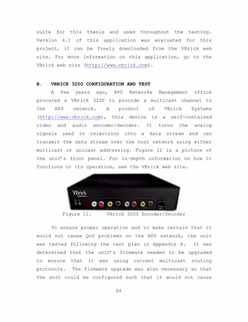
64
suite for this thesis and used throughout the testing.
Version 4.1 of this application was evaluated for this
project, it can be freely downloaded from the VBrick web
site. For more information on this application, go to the
VBrick web site (http://www.vbrick.com).
B. VBRICK 3200 CONFIGURATION AND TEST
A few years ago, NPS Networks Management office
procured a VBrick 3200 to provide a multicast channel to
the NPS network. A product of VBrick Systems
(http://www.vbrick.com), this device is a self-contained
video and audio encoder/decoder. It turns the analog
signals used in television into a data stream and can
transmit the data stream over the host network using either
multicast or unicast addressing. Figure 12 is a picture of
the unit’s front panel. For in-depth information on how it
functions or its operation, see the VBrick web site.
Figure 12. VBrick 3200 Encoder/Decoder
To ensure proper operation and to make certain that it
would not cause QoS problems on the NPS network, the unit
was tested following the test plan in Appendix A. It was
determined that the unit’s firmware needed to be upgraded
to ensure that it was using current multicast routing
protocols. The firmware upgrade was also necessary so that
the unit could be configured such that it would not cause
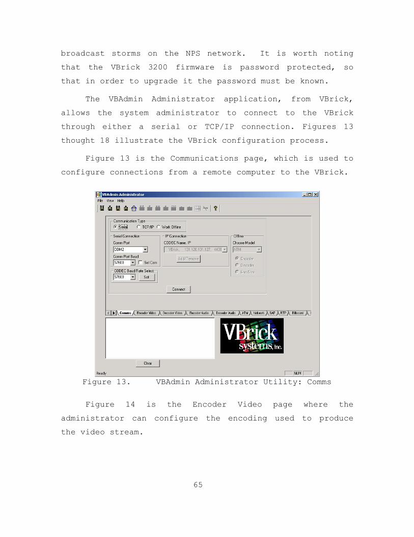
65
broadcast storms on the NPS network. It is worth noting
that the VBrick 3200 firmware is password protected, so
that in order to upgrade it the password must be known.
The VBAdmin Administrator application, from VBrick,
allows the system administrator to connect to the VBrick
through either a serial or TCP/IP connection. Figures 13
thought 18 illustrate the VBrick configuration process.
Figure 13 is the Communications page, which is used to
configure connections from a remote computer to the VBrick.
Figure 13. VBAdmin Administrator Utility: Comms
Figure 14 is the Encoder Video page where the
administrator can configure the encoding used to produce
the video stream.
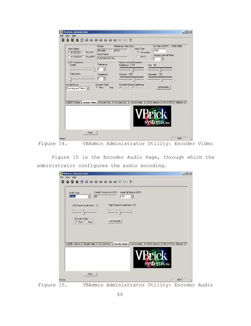
66
Figure 14. VBAdmin Administrator Utility: Encoder Video
Figure 15 is the Encoder Audio Page, through which the
administrator configures the audio encoding.
Figure 15. VBAdmin Administrator Utility: Encoder Audio
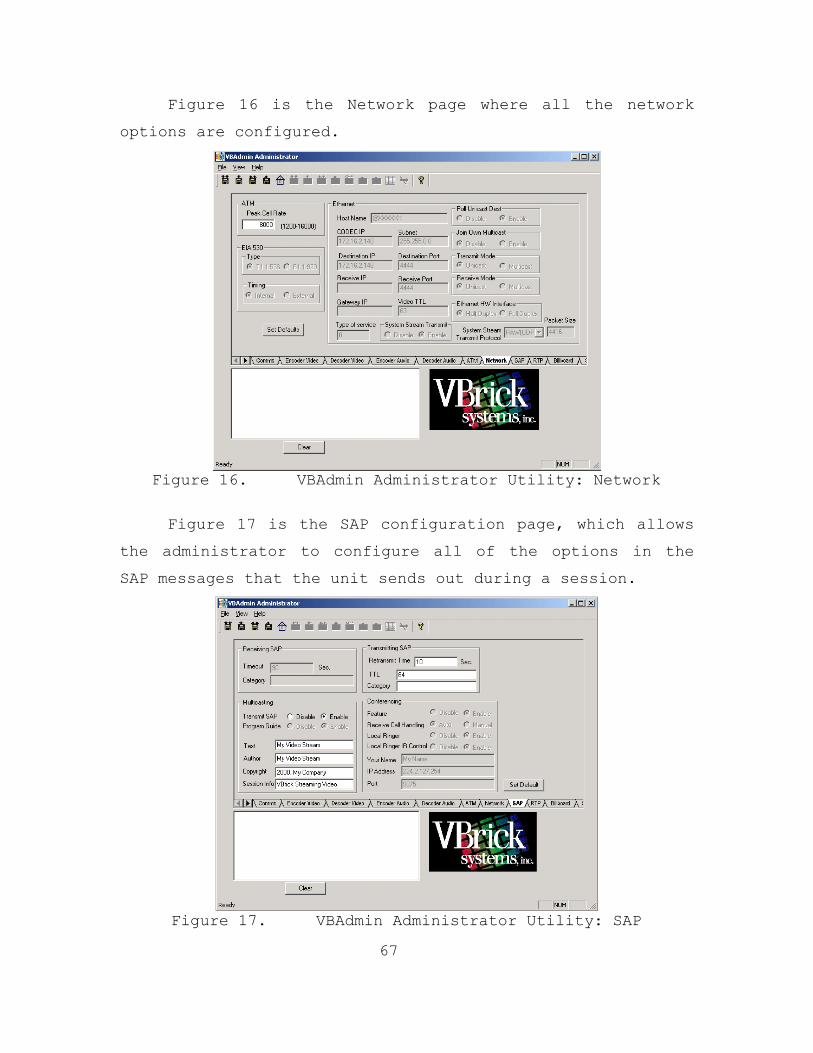
67
Figure 16 is the Network page where all the network
options are configured.
Figure 16. VBAdmin Administrator Utility: Network
Figure 17 is the SAP configuration page, which allows
the administrator to configure all of the options in the
SAP messages that the unit sends out during a session.
Figure 17. VBAdmin Administrator Utility: SAP

68
Figure 18 is of the Real Time Protocol (RTP)
configuration page where the transmission of separate audio
and video streams is controlled.
Figure 18. VBAdmin Administrator Utility: RTP
All the options, and more, on these pages were
modified and tested using Ethereal and SolarWinds to ensure
that the most efficient and standard data stream possible
was produced. During this process several problems were
discovered and corrected. The unit went from utilizing 3.5
Mbps of bandwidth at the start of the test to only 1.8 Mbps
at the end. The primary cause was the RTP configuration.
The RTP transmit was enabled causing the unit to send out 3
simultaneous multicast streams; an audio/video composite
stream, an audio stream, and a video stream. The composite
stream was all that was used by the VBrick Player
application so the other two streams were superfluous.
Other problems that were corrected include the gateway IP
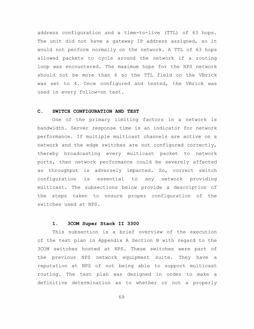
69
address configuration and a time-to-live (TTL) of 63 hops.
The unit did not have a gateway IP address assigned, so it
would not perform normally on the network. A TTL of 63 hops
allowed packets to cycle around the network if a routing
loop was encountered. The maximum hops for the NPS network
should not be more than 4 so the TTL field on the VBrick
was set to 4. Once configured and tested, the VBrick was
used in every follow-on test.
C. SWITCH CONFIGURATION AND TEST
One of the primary limiting factors in a network is
bandwidth. Server response time is an indicator for network
performance. If multiple multicast channels are active on a
network and the edge switches are not configured correctly,
thereby broadcasting every multicast packet to network
ports, then network performance could be severely affected
as throughput is adversely impacted. So, correct switch
configuration is essential to any network providing
multicast. The subsections below provide a description of
the steps taken to ensure proper configuration of the
switches used at NPS.
1. 3COM Super Stack II 3300
This subsection is a brief overview of the execution
of the test plan in Appendix A Section B with regard to the
3COM switches hosted at NPS. These switches were part of
the previous NPS network equipment suite. They have a
reputation at NPS of not being able to support multicast
routing. The test plan was designed in order to make a
definitive determination as to whether or not a properly
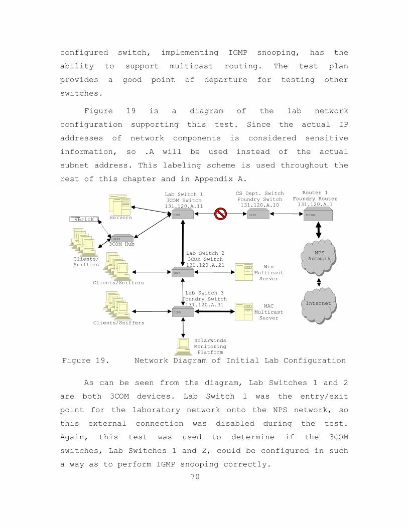
70
configured switch, implementing IGMP snooping, has the
ability to support multicast routing. The test plan
provides a good point of departure for testing other
switches.
Figure 19 is a diagram of the lab network
configuration supporting this test. Since the actual IP
addresses of network components is considered sensitive
information, so .A will be used instead of the actual
subnet address. This labeling scheme is used throughout the
rest of this chapter and in Appendix A.
Figure 19. Network Diagram of Initial Lab Configuration
As can be seen from the diagram, Lab Switches 1 and 2
are both 3COM devices. Lab Switch 1 was the entry/exit
point for the laboratory network onto the NPS network, so
this external connection was disabled during the test.
Again, this test was used to determine if the 3COM
switches, Lab Switches 1 and 2, could be configured in such
a way as to perform IGMP snooping correctly.
Lab Switch 3 Foundry Switch 131.120.A.31
Lab Switch 2 3COM Switch 131.120.A.21
Router 1 Foundry Router131.120.A.1
CS Dept. Switch Foundry Switch 131.120.A.10
Lab Servers
Clients/Sniffers
VBrick
Lab Switch 1 3COM Switch 131.120.A.11
Clients/Sniffers
Win Multicast Server
MAC Multicast Server
NPS Network
Internet
3COM Hub
Clients/ Sniffers
SolarWinds Monitoring Platform
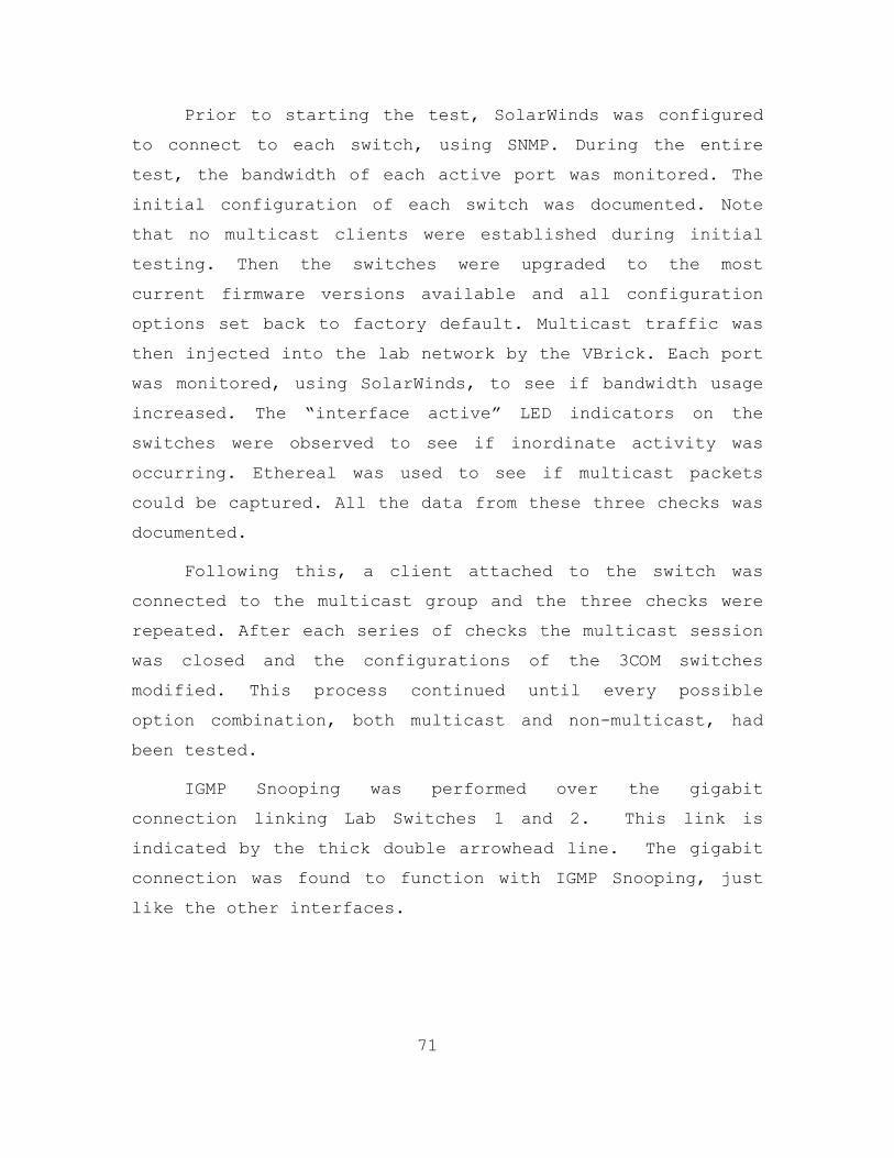
71
Prior to starting the test, SolarWinds was configured
to connect to each switch, using SNMP. During the entire
test, the bandwidth of each active port was monitored. The
initial configuration of each switch was documented. Note
that no multicast clients were established during initial
testing. Then the switches were upgraded to the most
current firmware versions available and all configuration
options set back to factory default. Multicast traffic was
then injected into the lab network by the VBrick. Each port
was monitored, using SolarWinds, to see if bandwidth usage
increased. The “interface active” LED indicators on the
switches were observed to see if inordinate activity was
occurring. Ethereal was used to see if multicast packets
could be captured. All the data from these three checks was
documented.
Following this, a client attached to the switch was
connected to the multicast group and the three checks were
repeated. After each series of checks the multicast session
was closed and the configurations of the 3COM switches
modified. This process continued until every possible
option combination, both multicast and non-multicast, had
been tested.
IGMP Snooping was performed over the gigabit
connection linking Lab Switches 1 and 2. This link is
indicated by the thick double arrowhead line. The gigabit
connection was found to function with IGMP Snooping, just
like the other interfaces.

72
Figure 20. 12 Port 3COM Switch Multicast Configuration
Figure 21. 24 Port 3COM Switch Multicast Configuration

73
Figures 20 and 21 above show the web interfaces for
the 3COM switches used at NPS. The FastIP option has to be
enabled on both switches so that the gigabit link will work
properly and translate from gigabit speed to the 100 Mbps
interfaces. The IEEE 802.1p Multicast Learning options
enable the Generic Attribute Registration protocol (GARP)
and GARP Multicast Registration Protocol (GMRP) to allow
registration of end-stations with multicast groups. GMRP is
protocol-independent, which means that it can be used on
all LANs and VLANs that contain network devices and end-
stations which conform to IEEE 802.1p. This type of
multicast is not currently part of the NPS network and is
thus not enabled. The IGMP Multicast Learning option
enables IGMP Snooping to register end-stations with
multicast groups through IP-supporting network devices. It
should be used on all LANs and VLANs that contain an IP
router and other network devices that support IP. This is
the configuration of the NPS network, so the IGMP Multicast
Learning option is enabled. [21]
The test determined that the configurations shown in
Figures 20 and 21 functioned best for multicast on the NPS
network. During testing a significant discovery occurred.
It was found that the 3COM switches did work with
multicast, but have a nonstandard implementation of IGMP
Snooping. As was stated before, a switch utilizing IGMP
Snooping should not relay multicast traffic to a port
unless a client connected to the port is sending IGMP
messages for a multicast group. In this case, the 3COM
switches were broadcasting the multicast traffic to every
port until a client joined the session and began sending
IGMP messages. At that point the switch’s IGMP Snooping
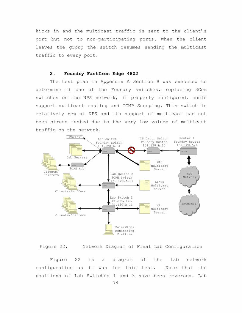
74
kicks in and the multicast traffic is sent to the client’s
port but not to non-participating ports. When the client
leaves the group the switch resumes sending the multicast
traffic to every port.
2. Foundry FastIron Edge 4802
The test plan in Appendix A Section B was executed to
determine if one of the Foundry switches, replacing 3Com
switches on the NPS network, if properly configured, could
support multicast routing and IGMP Snooping. This switch is
relatively new at NPS and its support of multicast had not
been stress tested due to the very low volume of multicast
traffic on the network.
Figure 22. Network Diagram of Final Lab Configuration
Figure 22 is a diagram of the lab network
configuration as it was for this test. Note that the
positions of Lab Switches 1 and 3 have been reversed. Lab
Lab Switch 1 3COM Switch 131.120.A.11
Lab Switch 2 3COM Switch 131.120.A.21
Router 1 Foundry Router131.120.A.1
CS Dept. Switch Foundry Switch 131.120.A.10
Lab Servers
Clients/Sniffers
VBrick Lab Switch 3
Foundry Switch 131.120.A.31
Clients/Sniffers
Linux Multicast Server
Win Multicast Server
NPS Network
Internet
3COM Hub Clients/ Sniffers
MAC Multicast Server
SolarWinds Monitoring Platform

75
Switch 3 is now the entry/exit point for the laboratory
network to the NPS network, so this external connection was
disabled during the test. An additional test objective was
to determine whether or not the Foundry switch’s IGMP
Snooping would prevent downstream, non-IGMP enabled
switches from being flooded.
Prior to starting the test, SolarWinds is configured
to connect to each switch, using SNMP. The bandwidth of
usage of each port was monitored throughout the test. As
with the 3COM switches, the Foundry switch’s original
configuration was recorded and the switch was upgraded to
the most current firmware versions available with all
configuration options set back to the factory defaults.
Multicast traffic was then injected into the lab network
using the VBrick box. SolarWinds was used to monitor
whether any port’s bandwidth utilization increased after
the multicast traffic was injected. The “interface active”
LED indicators on the switch were observed to see if any
inordinate activity was occurring. Ethereal was used to
determine if multicast traffic could be captured. The data
from these three checks was logged. A client attached to
the switch was then connected to the multicast group and
the three checks were repeated. The configuration of the
Foundry switch was then modified and the process continued
until every possible option combination had been tested,
including both multicast and non-multicast options.

76
Figure 23. 48 Port Foundry Switch Multicast
Configuration
Figure 23 above, is an example of the web-based
configuration interface used for the Foundry switches at
NPS. The IP Multicast option enables the switch’s multicast
traffic reduction capability. The IGMP option enables
either active or passive IGMP Snooping to register end-
stations, associated with multicast groups, with IP-
supporting network devices. The active mode allows the
switch to actively seek multicast groups to add to its
(S,G) table. Necessary additions are identified by sending
out IGMP messages. This operation mode should not be used
in networks with routers, as they perform this function.
The passive mode is used in networks with routers. In this
case, the switch actively listens for multicast groups to

77
add to its (S,G) table but will not send any IGMP messages.
The passive mode is the appropriate configuration for the
NPS network. [22]
The test revealed that the configuration shown in
Figure 23 functioned best for multicast on the NPS network.
It was observed that the switch worked correctly with
multicast and has a standard implementation of IGMP
Snooping. During this test, Lab Switches 1 and 2 were
monitored to see if an inordinate amount of traffic was
observed on their ports, as none of their clients were
members of a group. The Foundry switch protected the 3COM
switches from the multicast traffic, eliminating the
broadcasting of multicast traffic when no clients were
multicast group members.
D. ROUTER IGMP TEST
The Foundry router is a primary component of the NPS
network and proper operation in terms of multicast is
essential if multicast routing is to be exploited on the
network. For this reason, the router’s ability to support
multicast and IGMP required verification. Since a Foundry
router could not be spared from the operational network, a
short duration test on the operational computer science
edge router was performed with minimal risk to the NPS
network. The router configuration could not be altered
while it was active, so it was tested using the
configuration shown in Figure 24. A multicast server
(VBrick), multicast client (VBrick Player), and sniffer
(laptop with Ethereal) were each connected to a different
port on the router. Then packet capture was initiated on
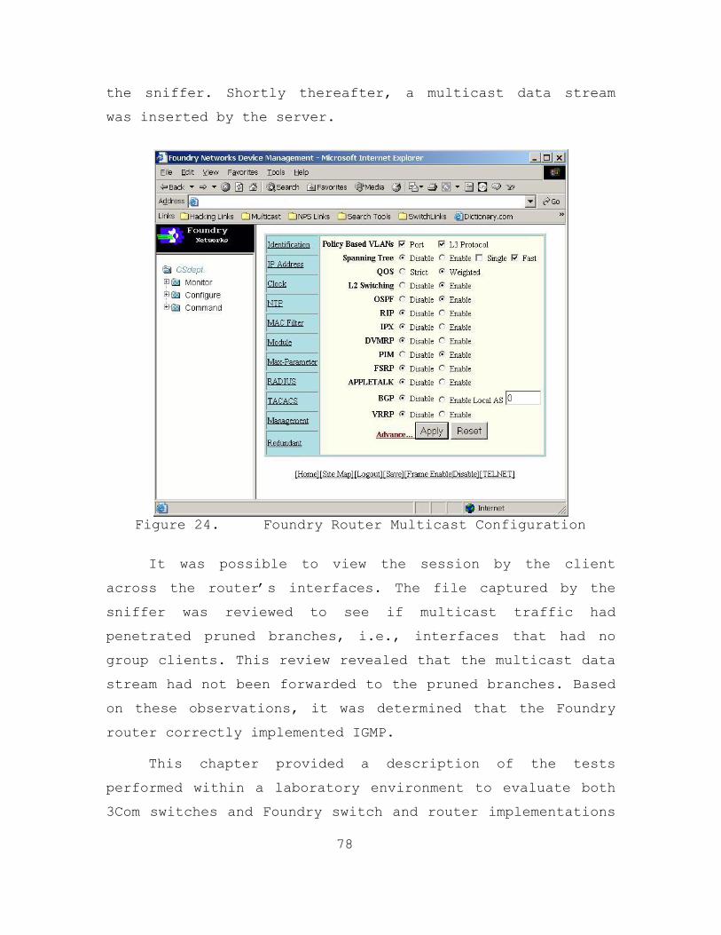
78
the sniffer. Shortly thereafter, a multicast data stream
was inserted by the server.
Figure 24. Foundry Router Multicast Configuration
It was possible to view the session by the client
across the router’s interfaces. The file captured by the
sniffer was reviewed to see if multicast traffic had
penetrated pruned branches, i.e., interfaces that had no
group clients. This review revealed that the multicast data
stream had not been forwarded to the pruned branches. Based
on these observations, it was determined that the Foundry
router correctly implemented IGMP.
This chapter provided a description of the tests
performed within a laboratory environment to evaluate both
3Com switches and Foundry switch and router implementations

79
of IGMP Snooping. The tests demonstrated the worthiness of
these network devices to limit default broadcasting of
multicast traffic. Chapter V will provide a similar
account of the testing performed on the NPS production
network.

80
THIS PAGE INTENTIONALLY LEFT BLANK

81
V. NETWORK TESTING, DATA ANALYSIS, AND RESULTS
This chapter provides the rational behind and an in-
depth description of each of the three tests performed on
the NPS production network. It also describes how data was
collected, provides an analysis of that data, and presents
the findings based on that analysis. The tests were
performed on the operational NPS network and thus profuse
precautions were taken to reduce the possibility of network
failure. Each test was conducted to examine different
factors regarding multicasting on the NPS network. It is
believed that the test plans provided in Appendix B will be
useful for pre-implementation testing of legacy networks
where employment of multicast functionality is being
considered. The information in this chapter will help to
better explain how the test plans were implemented on the
NPS network.
A. PROCEDURE FOR NETWORK DATA ANALYSIS
Analyzing the data collected during network testing
quickly became a critical problem due to its huge quantity.
During the Initial Test, approximately 2.33 GB of data was
captured by six sniffers. In the Clarification/Load Test,
about 2.29 GB of data was collected by one sniffer. In the
final 24-hour test, over 5.05 GB of data was collected. On
top of this, SolarWinds collected bandwidth usage data on
every port of every hub, switch, and router directly
involved in the test. In fact, SolarWinds was used to
gather data on bandwidth utilization across the network
throughout the test period, to ensure that a representative
82
collection was obtained during each test. As noted, the
data gathered during these tests by the sniffers and
SolarWinds was enormous. Thus, doing a complete, thorough
analysis of the data could take years. So the following
techniques and criteria were established to allow analysis
of the data in the given timeframe.
1. Packet Capture Analysis
To analyze the enormous amount of data captured by the
sniffers it was necessary to setup a specific procedure to
analyze each file and the data as a whole. To begin with,
each file was given a cursory examination to see what
multicast protocols and data streams were present on the
respective network segment. Any anomalous information in
the capture files was then noted. Then the capture data
files were merged using mergecap, an application that
accompanied the Ethereal installation. This program can be
used to combine two saved capture files, merging their
packets in chronological order based on timestamp, into a
single output file. Using this program, the multiple
capture files from each test were combined into a single
file for that test. From these huge files, the multicast
data streams were then extracted and saved to another file.
Then the multicast routing packets were extracted and saved
to yet another file. Finally, everything that is not
multicast related was saved to a separate file. These three
files were then compared in order to evaluate the effect
that a multicast load placed on a network. Since one of the
main focuses of this thesis is to determine if the NPS
network can support multicast, this load comparison is
critical to the findings of this thesis.
83
2. SolarWinds Data Analysis
Since this application provides for data collection,
analysis, and display, no procedure was required for the
data it collected. But, since this application collects
bandwidth usage data for every active port on every network
component it monitors, this data must be limited to only
relevant ports during test timeframes. Charts of this
information will be used throughout this chapter. They
should provide the reader with insight into each test’s
findings.
B. INITIAL TEST
This test’s primary goal was to determine if the NPS
network could support multicast traffic across its core
backbone without causing the typical network traffic to
experience QoS problems. Other goals for this test were to
verify that no multicast loop in the network existed, PIM-
DM worked correctly across the backbone, and subnets
without PIM-DM enabled did not become flooded with
multicast traffic. It was conducted between 1330 and 1430
on June 30, 2003. The test plan used for this initial test
is in Section A of Appendix B.
1. Test Description
Figure 20 is the network diagram used during this
test. It shows the applicable network components and their
relationship to each other. As a reminder, the actual IP
addresses of network components is considered sensitive
information, so .A, .B, and .C will be used instead of the
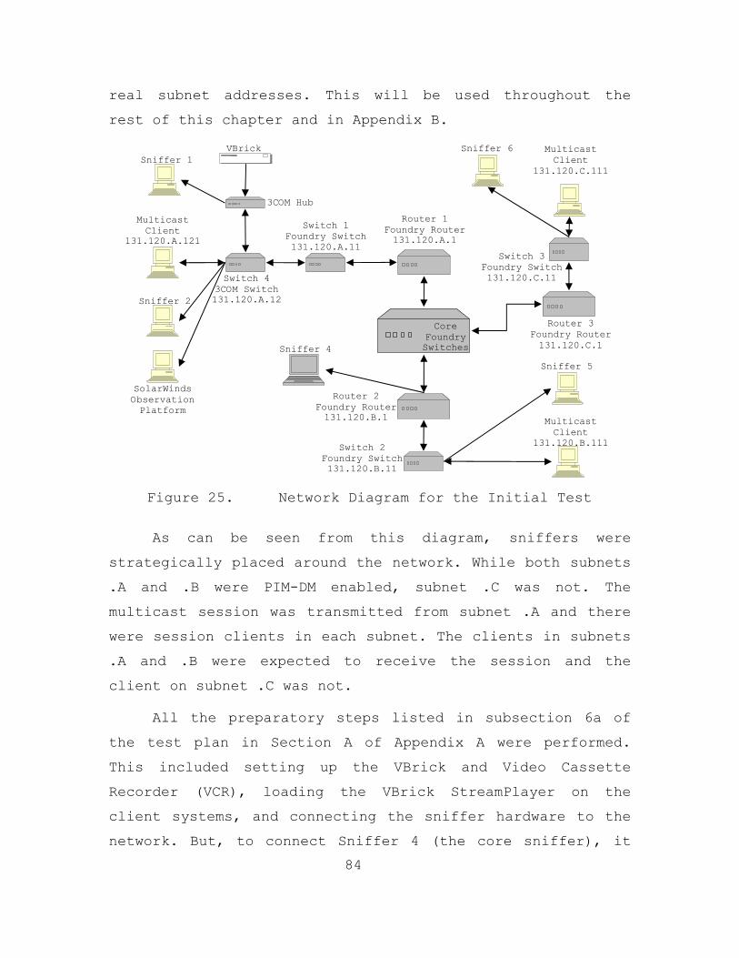
84
real subnet addresses. This will be used throughout the
rest of this chapter and in Appendix B.
Figure 25. Network Diagram for the Initial Test
As can be seen from this diagram, sniffers were
strategically placed around the network. While both subnets
.A and .B were PIM-DM enabled, subnet .C was not. The
multicast session was transmitted from subnet .A and there
were session clients in each subnet. The clients in subnets
.A and .B were expected to receive the session and the
client on subnet .C was not.
All the preparatory steps listed in subsection 6a of
the test plan in Section A of Appendix A were performed.
This included setting up the VBrick and Video Cassette
Recorder (VCR), loading the VBrick StreamPlayer on the
client systems, and connecting the sniffer hardware to the
network. But, to connect Sniffer 4 (the core sniffer), it
Switch 1 Foundry Switch 131.120.A.11
Sniffer 4
Multicast Client
131.120.B.111
VBrick
Switch 4 3COM Switch 131.120.A.12
3COM Hub
Multicast Client
131.120.A.121
Sniffer 1
Sniffer 2
Router 3 Foundry Router131.120.C.1
Multicast Client
131.120.C.111
Sniffer 6
Sniffer 5
SolarWinds Observation Platform
Router 1 Foundry Router 131.120.A.1
Router 2 Foundry Router131.120.B.1
Core Foundry Switches
Switch 3 Foundry Switch 131.120.C.11
Switch 2 Foundry Switch 131.120.B.11

85
was necessary to setup a port on Router 2 to mirror all
traffic from and to the core switches. Once the mirrored
port was setup, the core sniffer was connected and
configured to collect packets. After testing the core
sniffer, it was determined that the sheer volume of data
collected during a capture of an hour of the full core data
stream might be too large to effectively analyze. So, the
volume was reduced by adding a multicast filter in
Ethereal. The filter string used was “ether[0] & 1 != 0”.
This reduced the packets collected to only those that where
multicast in nature.
Next the test began packet capture by all sniffers. A
multicast data stream was then injected into the network.
This was done with the VBrick, which converted the signal
from the VCR into UDP packets for injection into the
network. For the first ten minutes following initial stream
insertion, no clients were allowed to attempt connection to
the multicast session. This portion of the sniffer capture
provided a client-free multicast traffic pattern of the NPS
network.
Ten minutes into the test the client computers
attempted to connect to the multicast session using the
VBrick StreamPlayer application. The .A subnet client could
both see and join the session, while the client on the .B
subnet was unable to see the session but could join it
manually, and the .c subnet client could not see the
session and attempts to connect manually failed. Thus, at
this point it appears that the Foundry routers implement
PIM-DM correctly; forwarding multicast packets to enabled
routers and blocking them to disabled ones.

86
During the entire test NOC personnel monitored the
network to ensure that its QoS did not degrade. This
included monitoring the CPU usage of the .A, .B, and .C
routers. All three routers maintained an average of four
percent CPU usage throughout the test with dips to two
percent and spikes to as much as six percent. The NOC does
not currently maintain this data for any length of time but
according to NOC personnel this average is normal for that
time of day. No abnormally high readings were observed
during the test and the system appeared to handle the
multicast load without a problem.
After the hour ended, the VBrick StreamPlayers closed
out the multicast session and the data stream from the
VBrick was terminated. Packet capture by the sniffers was
ended and the data files were saved using the format
“‘NetData’-Date-Time-IPAddress.eth.” The italicized words
in the file names were replaced with the IP-address of the
capture system and the date and time at which the test
ended. The data in these capture files and the data
gathered by SolarWinds, along with the observations made
during the test are analyzed in Subsection 3 below.
2. Problems Encountered
This subsection describes the problems encountered
before, during, and after the initial test. This
information was integrated into the test plan where
possible to enhance the revised test plan for follow-on
tests. Appendix B contains both plan versions.
In the initial rough draft of the test plan, the
multicast data stream from the VBrick was to come from a

87
fourth subnet. This subnet could not be used because its
router did not have PIM enabled, and to enable it the
router would have to be reinitialized. This could not be
done on the operational network during the work day due to
its adverse affects on non test traffic. To alleviate this
problem, the VBrick was reconfigured to operate on the .A
subnet and moved to that subnet. Thus, the network diagram
above shows the final network configuration for the test.
The next problem encountered was connecting the core
sniffer to the core. Initially, the sniffer was to be
attached directly to the core, to capture packets directly
from it. This proved to be impossible because the sniffer’s
network card was a standard Ethernet connection and only
able to operate at 100 Mbps while the core switch operates
at up to 8 Gbps. To overcome this, the core trunk into the
.B subnet was mirrored to a 100 Mbps port on that subnet.
The core sniffer was attached to this port and worked
appropriately.
Another problem was locating a client on the .B
subnet. A standard wired client could not be located in the
timeframe required for this test so a laptop using a
wireless connection was used. This wireless connection to
the .B LAN is thought to be the reason behind this client
not being able to see the session on the VBrick
StreamPlayer (the SAP/SDP messages were not forwarded over
the wireless connection). A manual connection was made but
it was intermittent and very unreliable. Further research
into this area is beyond the scope of this thesis.
The core switches are the nucleus of the NPS network
and NOC personnel guard them accordingly. Until the initial
88
multicast test was proven to be harmless and the author
trustworthy, the monitoring SNMP string and IP addresses
was not provided. Thus, the Core Switches could not be
connected to SolarWinds for monitoring. In both follow-on
tests, the core was monitored by SolarWinds.
The final problem encountered during the Initial Test
was an application error on the sniffer connected to the .B
subnet. For some reason, the save operation in Ethereal
failed while saving the capture file to disk. It is unknown
exactly why the save failed but it is thought that limited
hard-drive space on the system was the cause. This problem
could not be mitigated but the core capture showed that
multicast had been forwarded to this router.
3. Data Analysis
As was stated before, roughly 2.33 GB of data was
captured during this test. Analysis of the individual
capture files revealed some very interesting things. The
capture file from the sniffer attached to the hub with the
VBrick had some unexpected information in it. Since this
test was performed before the VBrick was configured as
described in the previous chapter, three multicast data
streams were observed; the first was a video stream, the
next was an audio stream, and the final one was a combined
audio/video stream. All of these streams were accompanied
by their IGMP and SAP/SDP routing messages. The VBrick was
sending out IGMP messages approximately every 60 seconds
and SAP/SDP messages about every 10 seconds. Further
examination of the captured packets showed that every one
generated by the VBrick had a TTL field value of 63. PIM-DM
89
hello messages from the .A router were also found in this
capture. This capture file accounted for the majority of
the data captured during this test.
The capture file from the client/sniffer attached to
the 3COM switch on the .A segment only contained packets
from the VBrick’s combined stream. Examination of this
capture file show that the client was also sending out IGMP
messages approximately every 60 seconds and SAP/SDP
messages were received about every 10 seconds. PIM-DM hello
messages from the .A router were also captured here.
The core sniffer’s capture file was relatively small
due to the use of the multicast filter, described above,
and the problems encountered with the .B subnet client.
None-the-less, some interesting discoveries were made. The
three multicast streams generated by the un-configured
VBrick were present. These streams were periodically
broadcast to the entire core network, as is done in PIM-DM
routing when no clients are present. PIM, DVMRP, IGMP, and
SAP/SDP routing messages were all present. The IGMP and
DVMRP messages were not expected and accounted for the
majority of the captured routing packets. This is
irregular, since PIM-DM is the routing protocol used for
router-to-router routing on the NPS network. Interestingly,
the captured SAP/SDP messages were not for the test
sessions. These messages appear to have come from the
Modeling, Virtual Environments and Simulation (MOVES)
Institute subnet. It is speculated that the absence of the
test stream’s SAP/SDP message was due to the configuration
of the VBrick.

90
There was no capture from the .B subnet due to an
application error. The .C network segment collection did
have captured multicast packets in it, but they were all
from within that subnet. No multicast packets from outside
the .C subnet were present in the capture file.
The following diagrams were generated by SolarWinds
using the data it collected during this test. Figure 26 is
a graph of the bandwidth usage across the port on Switch 4,
which was connected to the hub to which the VBrick was
attached during the test. It shows that both the incoming
and outgoing bandwidth across this port was very low until
13:30 when the test started. At that point, both send and
receive traffic jumped to about 3.5 Mbps and remained there
for the duration of the test. The received traffic reflects
how IGMP Snooping works in that the switch is sending the
data back to this port because of the IGMP messages being
sent by the VBrick.

91
Figure 26. Switch 4 Initial Test Bandwidth Usage Chart
Figure 27 is a chart of the bandwidth usage on the
router port for the laboratory connection. As you can see,
this connection is only receiving the data stream. IGMP
limits the return traffic as this is the stream’s source.
Figure 27. Router 1 Initial Test Bandwidth Usage Chart
4. Test Results
The results of this test can be broken into two
categories; equipment configuration and findings. This test
revealed several configuration problems with the equipment
used for the test.
a. Equipment Configuration
This subsection contains the results of the
configuration errors discovered during the test. By
examining the data capture file from Sniffer 1 it was

92
determined that the VBrick was generating three multicast
streams when it was only supposed to be generating the one
combined data stream. So, the VBrick needed to be
reconfigured.
The final configuration problem had to do with
SolarWinds. In order for this application to provide a
clearer picture of the bandwidth usage during the next
test, SolarWinds had to be connected to all affected
network components, including the core switches. Thus,
SolarWinds needed to be connected into more of the
network’s switches and routers to increase its network
coverage.
b. Findings
This subsection contains the finding from the
test that relate to the NPS Network. Review of the TTL
fields in the captured multicast packets from the core
capture file showed that they were only decremented once as
the packet traversed the .A router. This implies that there
is no multicast loop in the NPS core network.
Next, the CPU usage rate on Router 1, Router 2,
and Router 3, monitored by NOC personnel, showed no
noticeable change from pretest levels. They maintained an
average utilization level of four percent before, during,
and after the test. This indicates that the introduced
multicast streams had no noticeable impact on the NPS
network’s QoS level.
As for the network components, IGMP on the
131.120.A.1 Foundry router worked in accordance with IETF
standards, as expected. IGMP Snooping on the Foundry

93
switches worked in accordance with IETF standards, as well.
Finally, IGMP Snooping did not function as expected on the
3COM switches, as was also observed in the laboratory
tests.
The multicast session generated on the
131.120.A.1 segment was visible, across the network
backbone, at the multicast enabled 131.120.B.1 router but
not on the multicast disabled 131.120.C.1 router. This
indicates that PIM-DM functioned as per the IETF standards
described in Chapter III. Subnets that were not PIM-DM
enabled did not receive the multicast stream or the SAP/SDP
messages. Further more, clients on these subnets were not
able to force the router to forward these streams by
joining them manually.
C. CLARIFICATION/LOAD TEST
The primary goal of the Clarification/Load Test was to
clarify the results of the initial multicast test and
determine the impact of multiple multicast streams on the
NPS network’s supported QoS level. The additional goal of
this test was to ascertain if SAP/SDP packets could be used
across the NPS network backbone. This test utilized the
refined test plan located in Section B of Appendix B. It
was conducted between 0530 and 1130 on July 18, 2003 with
0930 and 1030 as the actual test timeframe. The actual
test procedure was as follows: 4 hours for section 5a (test
preparation), 1 hour for section 5b (testing), and 1 hour
for section 5c (test wrap-up).
1. Test Description

94
This test was accomplished by inserting seven data
streams, totaling approximately 8 Mbps, into the network.
This was done while monitoring the network traffic, using
SolarWinds and the core sniffer, and monitoring the
routers’ CPU usage manually.
Figure 28 diagrams the test configuration. It shows
the relevant network components and their relationship to
each other.
Figure 28. Network Diagram for the Clarification Test
As can be seen from this diagram, only the core
sniffer was used for this test. Both routers on subnet .A
and .B were PIM-DM enabled. Subnets that are not PIM-DM
enabled were not included in this test based on the
findings of the Initial Test. All multicast sessions were
transmitted from subnet .A with the only pertinent session
client on the .B subnet. Using the VBrick StreamPlayer, the
client was expected to receive the session if entered
manually, but it was unsure whether the SAP/SDP messages
Router 2 Foundry Router 131.120.B.1
Switch 1 Foundry Switch 131.120.A.11
Multicast Server
131.120.A.111
Sniffer
Multicast Client
131.120.B.122
VBrick
Switch 4 3COM Switch 131.120.A.12
3COM Hub
SolarWinds Observation Platform
Switch 2 Foundry Switch 131.120.B.11
Router 1 Foundry Router 131.120.A.1
Core Foundry Switches

95
could cross the network backbone to display the session
information on the player.
All the preparatory steps listed in subsection 5a of
the test plan were performed. These included setting up the
VBrick and Video Cassette Recorder (VCR), as well as,
loading the VBrick StreamPlayer on the client system. It
was again necessary to setup a port on Router 2 to mirror
all traffic from the router’s core connection. Once the
mirrored port was setup, the core sniffer was connected and
configured to collect packets. To test the core sniffer and
provide a data point for multicast free network traffic, a
ten second capture of all the traffic on this core switch
was collected and saved to file. From the sheer volume of
data collected during this short period it was again
determined that an hour capture of the full core traffic
would be too large to effectively analyze and could
potentially overload the sniffer when multiple multicast
streams were introduced. So, to reduce the volume, the same
multicast filter used in Ethereal during the Initial Test
was used for this test. Here, again, it reduced the packets
collected to only those that where multicast in nature.
Once data capture was activated on the sniffer, the
multicast data stream from the VBrick was injected into the
network. This done, the VBrick StreamPlayer application on
the client was accessed to see if the session was visible
and could be joined. It was visible and the client was able
to join the session. For the first five minutes, the stream
from the VBrick functioned alone, at that point a second
stream was added using the VBrick StreamPump loaded on a
Windows 2000 server. At the client, this stream was also
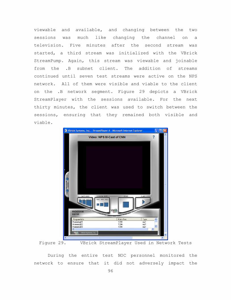
96
viewable and available, and changing between the two
sessions was much like changing the channel on a
television. Five minutes after the second stream was
started, a third stream was initialized with the VBrick
StreamPump. Again, this stream was viewable and joinable
from the .B subnet client. The addition of streams
continued until seven test streams were active on the NPS
network. All of them were visible and viable to the client
on the .B network segment. Figure 29 depicts a VBrick
StreamPlayer with the sessions available. For the next
thirty minutes, the client was used to switch between the
sessions, ensuring that they remained both visible and
viable.
Figure 29. VBrick StreamPlayer Used in Network Tests
During the entire test NOC personnel monitored the
network to ensure that it did not adversely impact the
97
supported level of QoS. This included monitoring all of the
network components and the CPU usage of the .A and .B
routers. No abnormal readings were observed during the test
and the network handled the multicast load without a
problem.
Upon completion of the capture period, it was noticed
that Ethereal had experienced an error and had closed
prematurely, without saving the capture file. This was the
primary problem encountered during this test and is
explained in greater detail in Subsection 2. All of the
files from the other capture devices were available. The
core sniffer was used to collect a “post-stream” data set.
These files and the data gathered by SolarWinds, along with
the observations made during the test, are analyzed in
subsection 3 below.
2. Problems Encountered
In the preparatory and test stages this test ran
relatively smoothly, with one minor problem. At the VBrick
StreamPlayer on the client, the data stream from the VBrick
began to experience more and more delay problems as new
data streams were added to the network. After the test was
complete, an investigation of the problem suggested that
the hub to which the VBrick was connected had caused the
problem. As more and more data streams were added to the
network, the switch forwarded them to the hub, which it in
turn forwarded to the 10 Mbps connection used by the
VBrick, essentially overloaded the connection. This caused
some of the UDP data stream packets to be lost as they
collided with the other multicast data stream packets
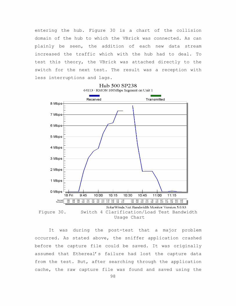
98
entering the hub. Figure 30 is a chart of the collision
domain of the hub to which the VBrick was connected. As can
plainly be seen, the addition of each new data stream
increased the traffic which with the hub had to deal. To
test this theory, the VBrick was attached directly to the
switch for the next test. The result was a reception with
less interruptions and lags.
Figure 30. Switch 4 Clarification/Load Test Bandwidth
Usage Chart
It was during the post-test that a major problem
occurred. As stated above, the sniffer application crashed
before the capture file could be saved. It was originally
assumed that Ethereal’s failure had lost the capture data
from the test. But, after searching through the application
cache, the raw capture file was found and saved using the
99
same naming format used in the Initial Test. The data in
this capture file was partially corrupted, with an ending
packet that exceeded the maximum limit. But it was possible
to eliminate this error and view the file up to that point.
The time stamps in the packets in this file were used to
determine that capture had taken place for about 48 minutes
of the test. After scrutinizing the sniffer, both hardware
and software, lack of hard-drive space on the capture
computer was deemed to be the most plausible cause of the
failure. Under this assumption, extra disk space was
procured in order to reduce the possibility of this
occurring during the final network test.
3. Data Analysis
Analysis of the pretest packet capture from the core
sniffer showed little multicast network traffic. Only the
PIM routing “Hello” messages between multicast enabled
routers were found in this capture file. But this is not a
solid data point due to the short capture time. Some
protocols may cycle at a rate larger than ten seconds, like
IGMP traffic, and it is possible that they were missed.
The recovered packet capture from the core sniffer
provided good insight into the network multicast structure.
First of all, the PIM and SAP/SDP messages were present and
working as expected. Next, the test data streams were
present. As new streams were added, their routing messages
and accompanying data packets were found. The IGMP messages
from the .B router and the client on that subnet were also
found. The latter was unexpected and could not be explained
by NOC personnel, so a technical assistance call was placed

100
to Foundry, Inc., to request assistance. According to a
technical representative for the company, the router
interface will send IGMP queries to its downstream hosts to
see if there is any client listening for the multicast
session, and that this is normal. This makes since if only
IGMP messages from the router were found in the core
captures, but this was not the case. In the core captures,
IGMP messages from the client on the .B network were found.
This indicates that this router is forwarding IGMP traffic,
which should not occur. IGMP should not be on the backbone
due to the possibility of creating redundant routing
entries in host router (i.e., an entry for the same route
in both the (S,G) table created by IGMP and an entry in the
normal routing table created by PIM-DM).
Analysis of the post-test packet capture from the core
sniffer revealed somewhat the same traffic patterns as the
pretest capture, the only difference being the addition of
a small amount of multicast traffic from the sessions as
they were closed.
The 131.120.A.1 and 131.120.B.1 router both maintained
an average of six percent CPU usage throughout the test,
with dips to four percent and spikes to as much as eight
percent. Currently, the NOC does not maintain this type of
data for any length of time as a historical record but
according to NOC personnel this average is only slightly
above normal for that time of day.
Observation of the VBrick StreamPlayer application on
the client during the test indicated that SAP/SDP packets
were being transmitted across the NPS network backbone, as
all seven sessions were seen and joinable on the client.

101
All of the following charts were generated by
SolarWinds. Figure 31 is a chart of the bandwidth used on
the laboratory switch port that serves as the lab’s gateway
to the NPS network. The “stair step” pattern shows how the
bandwidth usage increased as new streams were added. The
missing data point at 1035 was unexpected and is surmised
to be the result of a lost packet.
Figure 31. Switch 4 Clarification/Load Test Bandwidth
Usage Chart
The left graph in Figure 32 shows the bandwidth usage
of the port receiving data from Switch 1 and the graph on
the right is the bandwidth usage of the port sending data
to the Core Switch.

102
Figure 32. Router 1 Clarification/Load Test Bandwidth
Usage Charts
Likewise, the left chart in Figure 33 is the bandwidth
usage of the port connected to Router 1 while the chart on
the right is for the port connected to Router 2. As a
reminder, this test was performed on a live network and
some fluctuation was expected. The large spike at the
beginning of the test time frame is just such an event.
Figure 33. Core Switch 1 Clarification/Load Test
Bandwidth Usage Charts

103
Figure 34 is a graph of the bandwidth usage for the
Router 2 port connected to the Core Switch. It shows that
the streams traversed the core network with just about the
same bandwidth usage as was put into the network.
Figure 34. Router 2 Clarification /Load Test Bandwidth
Usage Chart
These charts show the multicast bandwidth usage across
the NPS network, from the point were it was introduced to
the final destination router. This is relevant because it
proves that there is no multicast loop in the NPS network.
If there were, it would be plainly visible, since as
packets were retransmitted, the bandwidth usage would grow
exponentially for some time period.
4. Test Results

104
This test clarified and validated the results from the
Initial Test. It confirmed that there is no multicast loop
in the NPS network and that multicast data streams can be
used on the NPS Network without causing QoS issues for
normal network traffic.
Besides clarifying the first test’s finding, it was
determined that the NPS network can support multiple
multicast data streams without taxing its network
components. Furthermore, SAP/SDP messages can traverse the
NPS Network and provide session information to clients on
subnets with multicast enabled routers. All of these
results indicate that the NPS network has the ability to
not only support multicast, but support multiple sessions
with minimal or no impact on the QoS provided to the normal
network traffic. The Stress Test was used to validate this
assumption.
D. STRESS TEST
The primary goal of this test was to determine if the
NPS core network could handle multiple sustained multicast
data streams without impacting the network’s QoS. A further
goal of this test was to obtain packet captures from the
core during this extended time frame. This stress test
utilized the refined test plan located in Section B of
Appendix B with the exception of the time frame, and was
conducted between 10:30 on August 11, 2003 and 10:30 on
August 12, 2003. The actual timeframes for the test
procedure were as follows: 4 hour for section 5a (test
preparation), 24 hours for section 5b (testing), and 1 hour
for section 5c (test wrap-up).

105
1. Test Description
To perform this test, ten data streams totaling
approximately 15 Mbps, were initially inserted into the NPS
network. During the test additional streams were added to
the load and the maximum load on the network reached almost
24Mbps. This was done while autonomously monitoring the
network using SolarWinds and the core sniffer. As with the
other tests, NOC personnel manually monitored the network’s
components and the router’s CPU utilization. The core
sniffer accomplished a half hour capture of the network
traffic filtering out everything but multicast related
messages just after insertion of test traffic. During the
test, two types of captures were conducted every half hour.
The first type was a five-minute capture of the entire core
traffic flow; it was performed on the hour and half hour.
The second type was a five-minute multicast-filtered
capture of the core traffic; it was conducted at five
minutes past the hour and half hour. All of this data was
saved to the extra hard-drive procured for this effort,
using the naming convention described in the Initial Test.
Figure 35 depicts the applicable network components
and their relationship to each other during this test. The
primary difference between this diagram and the one used
for the last test is the VBrick’s connection to the
network. It is now connected directly to Switch 4. Only a
core sniffer was used. Both subnets .A and .B are PIM-DM
enabled and subnets that are not PIM-DM enabled were not
monitored during the test. Again, the multicast sessions
were transmitted from subnet .A and the only pertinent
session client was on the .B subnet. The VBrick
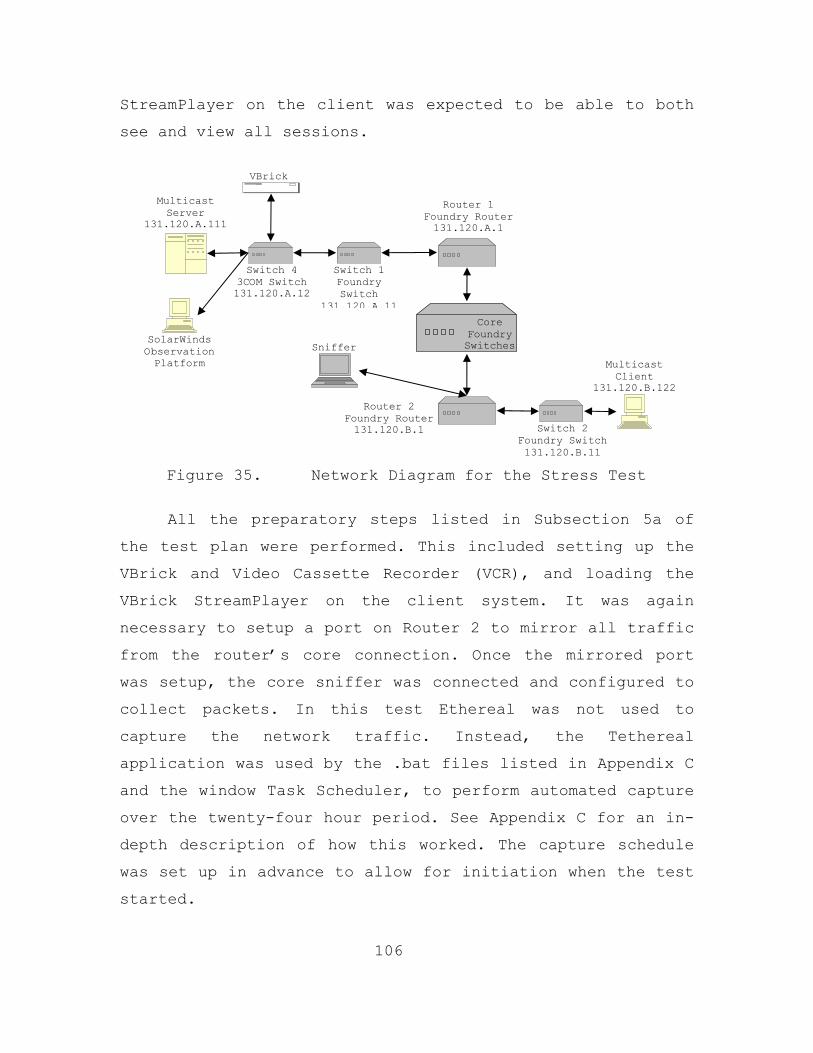
106
StreamPlayer on the client was expected to be able to both
see and view all sessions.
Figure 35. Network Diagram for the Stress Test
All the preparatory steps listed in Subsection 5a of
the test plan were performed. This included setting up the
VBrick and Video Cassette Recorder (VCR), and loading the
VBrick StreamPlayer on the client system. It was again
necessary to setup a port on Router 2 to mirror all traffic
from the router’s core connection. Once the mirrored port
was setup, the core sniffer was connected and configured to
collect packets. In this test Ethereal was not used to
capture the network traffic. Instead, the Tethereal
application was used by the .bat files listed in Appendix C
and the window Task Scheduler, to perform automated capture
over the twenty-four hour period. See Appendix C for an in-
depth description of how this worked. The capture schedule
was set up in advance to allow for initiation when the test
started.
Router 1 Foundry Router131.120.A.1
Router 2 Foundry Router 131.120.B.1
Switch 1 Foundry Switch
131.120.A.11
Switch 2 Foundry Switch 131.120.B.11
Multicast Server
131.120.A.111
Sniffer
Multicast Client
131.120.B.122
Core Foundry Switches
VBrick
Switch 4 3COM Switch 131.120.A.12
SolarWinds Observation Platform

107
The test was started by initiating the capture on the
core sniffer. With the sniffer capture enabled, the
multicast data streams from the VBrick and VBrick
StreamPump on the Windows 2000 Server were injected into
the network. The VBrick StreamPlayer in the client was
started and observed to see if the session was visible and
could be joined. All ten sessions were visible and the
client was able to join them. See Figure 29, in the last
section, for an example of what the VBrick StreamPlayer
looked like with the sessions available.
During this test period other multicast generation
systems were tested across the NPS backbone by another
thesis student. The other data streams account for the
abnormally high reading from about 12:00 to 18:00 on the
test day. The bandwidth usage diagram is shown in
Subsection 3.
One half hour into the test, the thirty minute capture
of the multicast filtered traffic flow ended. The resulting
capture file was about 449 MB in size. At this point the
periodic captures began. Initially, this appeared to be
working correctly, but a problem was soon discovered; the
five minute captures were stopping after only ten to twenty
seconds. An in-depth description of the problem follows in
the next subsection.
During the entire test, the NOC monitored the network
to ensure that its QoS did not degrade. This included
monitoring the CPU usage of the .A and .B routers. Both
routers maintained an average of eight percent CPU usage
throughout the test, with dips to four percent and spikes
to as much as ten percent. No abnormally high readings were
108
observed during the test and the network handled this large
multicast load without a problem.
After the twenty-four hour test period ended, packet
capture on the core sniffer was stopped. The VBrick
StreamPumps on the Windows 2000 server were closed out
ending their data streams and the data stream from the
VBrick was also stopped. Then the VBrick StreamPlayer in
the client was closed out. The capture files and the data
gathered by SolarWinds, along with the observations made
during the test, are analyzed in Subsection 3, below.
2. Problems Encountered
The only problem encountered during this test was the
premature termination of the capture application,
Tethereal, during network collection. It appeared that
Tethereal’s function was unstable when higher numbers of
streams were present on the backbone. The application’s
collection performance was sporadic. Often it would fail
after running for only a second or less, other times it
would capture the entire five minute period, and for
majority of the times it would collect data for ten to
twenty seconds before terminating the collection session.
At first, it was assumed that this was caused by the
massive amount of data being poured from an eight gigabits-
per-second connection into a one-hundred megabits-per-
second connection. But after examining the situation, it
now appears that a combination of factors caused this
problem. First, the funneling of a high-speed connection
into a low-speed connection was not conducive to the
capture. Second, the extra hard-drive space procured for

109
this test was attached through a 1.1 USB connection, which
limited the throughput to the unit to about 1 Mbps. Since
the capacity change was so dramatic, 8 Gbps to 1 Mbps, the
capture system’s memory probably filled to capacity and the
application failed. Third, Ethereal and its accompanying
applications might not have been designed to handle such a
massive amount of data efficiently, which would have
compounded the memory problem. Finally, the MSBlast virus
may have also been part of the cause. The period during
this test is when the virus was spreading across the NPS
network, probing for systems to infiltrate. The lower left
chart in Figure 36 shows a steady increase in the bandwidth
utilization across the core during the test, even though
the multicast streams bandwidth usage was stable, as shown
by the upper right chart in the same figure. This gradual
increase occurred throughout the test period and the
morning of August 12, 2003 after the virus was discovered
on the NPS network.
3. Data Analysis
Analysis of the initial half hour of collection of the
multicast-filtered core traffic indicated that the network
was handling the ten multicast data streams as expected.
Again, IGMP messages were noted, as in the previous tests.
Both types of periodic core captures ranged, in size
from as small as 92 KB to as large as 200 MB. Examination
indicated the capture durations were anywhere from less
that a second to the five minute limit. As for the content,
the traffic pattern was in keeping with that of the half-
hour capture.
110
Using mergecap all of the unfiltered captures were
combined into one file totaling about 2.484 GB. An
evaluation of this file provided the following information.
First, the multicast data streams made up 1.744 GB of this
file. This was the vast majority of the data present on
this link for the duration of the test. Second, the
multicast routing protocols made up only 4.536 MB of the
capture packets. Finally, normal traffic on this connection
made up 736 MB of the captured data. This indicates that
the routing overhead needed to support multicast is low and
will not affect QoS.
Network and router CPU observations performed by NOC
personnel were relatively normal. No network components
experienced QoS issues and the CPU usage of Routers 1 and 2
averaged about eight percent. This indicates that a network
load that averages about 15 Mbps continuously, does not
affect the QoS of the NPS network. With an eight gigabits-
per-second backbone it would be safe to assume that a much
larger multicast load could be placed on the core network
without impacting its QoS, but this would not be the
chokepoint of the network. The real bottleneck would be at
the routers and switches where the bandwidth is only 100
Mbps. If multiple data streams using close to the capacity
of the network segments bandwidth were requested by the
various users on a network segment, QoS would suffer. The
number of multicast sessions required to generate this
bandwidth could be as small as ten or as large as sixty-
five, depending on the stream sizes.
Figure 36 contains four graphs of the bandwidth
utilized by key network components during this test. The
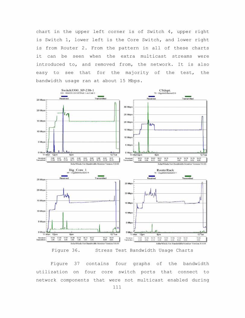
111
chart in the upper left corner is of Switch 4, upper right
is Switch 1, lower left is the Core Switch, and lower right
is from Router 2. From the pattern in all of these charts
it can be seen when the extra multicast streams were
introduced to, and removed from, the network. It is also
easy to see that for the majority of the test, the
bandwidth usage ran at about 15 Mbps.
Figure 36. Stress Test Bandwidth Usage Charts
Figure 37 contains four graphs of the bandwidth
utilization on four core switch ports that connect to
network components that were not multicast enabled during
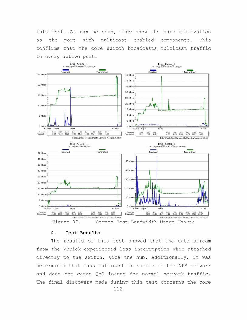
112
this test. As can be seen, they show the same utilization
as the port with multicast enabled components. This
confirms that the core switch broadcasts multicast traffic
to every active port.
Figure 37. Stress Test Bandwidth Usage Charts
4. Test Results
The results of this test showed that the data stream
from the VBrick experienced less interruption when attached
directly to the switch, vice the hub. Additionally, it was
determined that mass multicast is viable on the NPS network
and does not cause QoS issues for normal network traffic.
The final discovery made during this test concerns the core

113
switches. The ones used in the NPS network broadcast
multicast traffic to every active port except the one from
which it is received. Since this is a layer two switch and
PIM-DM is the routing protocol used across the core, there
is no current way to limit this behavior. Since the core
network currently has a bandwidth glut, 8 Gbps, this does
not presently pose a threat to the networks function or
QoS. But, in the future, as bandwidth usage increases, this
could become a problem.
In this chapter the network tests performed in support
of this thesis were described. The problems encountered,
analysis of the data, and results of the tests were
provided. These findings showed that the majority of the
NPS network components support standard multicast routing
and that the network can easily support multiple multicast
sessions.

114
THIS PAGE INTENTIONALLY LEFT BLANK

115
VI. CONCLUSION
Main stream educational systems are moving toward new
ways of doing business. They are looking for ways to enroll
and educate larger student populations and are even looking
at ways of having global student populations. Synchronous
distributed learning has the potential to fulfill this need
and profoundly change the educational systems throughout
the world. Some day soon, it will be possible for a student
to sit down at a computer that is across the campus, town,
state, country, or even the world, and participate in a
class as if in the same room. Multicast is the enabling
technology that can make this a reality. With a multicast
enabled Internet and the right supporting software and
hardware, classes will no longer have to be for just local
students. In fact, instructors will no longer have to be
local, they can be conduct class from anywhere in the world
and students can participate as if they were there with
them. All of this is Multicast Distributed Learning (MDL),
and it will be the classroom of the future. This is the
future of education and the United States military needs to
be at its forefront in order to provide its personnel with
essential training, at the diverse locations, within the
required timeframe.
But, with the military’s current training systems
primarily classroom oriented, and computer networks that
were not designed with multicast in mind, this educational
future seems a long way off. To move toward this future,
military training and education needs to start thinking in
terms of electronic distribution. Classroom lectures,

116
educational materials, homework, and even testing, needs to
be designed with this in mind. This will not only prime the
military training system for distributed learning but could
have the effect of making military training and education
more enjoyable and less stressful on both instructors and
students.
It should be noted that this may required a change in
mindset for military supervisors, as well, in that students
will need to be allowed the time to participate in these
distributed learning opportunities. While this may seem to
impact subordinate availability, the alternative of long
absences while in training status, involving increasing
travel costs, can be more adverse, often so much so that
training opportunities are either indefinitely postponed or
eliminated entirely. This can negatively impact both unit
readiness and personnel morale.
The next step in the process is to ensure that current
military networks are ready for this future. This is done
by ensuring that multicast is viable on them. Here is where
this thesis is relevant. Its findings will help identify
areas of the NPS network which require attention in order
to make the network ready for multicast applications. The
test plans and insight will provide the reader with a place
to start when testing their networks. Section A, below,
provides the findings of this thesis as it applies to the
NPS network. Section B contains recommendations for future
DOD distributed learning and multicast network services.
Finally, Section C is a list of follow-on work to this
thesis that needs to be conducted.

117
A. SUMMARY OF THESIS FINDINGS
It is hoped that the finding in this thesis will allow
all forms of multicast to benefit the faculty, staff, and
students at NPS. Multicast networking is an enabling
technology which can, if configured right, exponentially
reduce the load placed on a network by streaming media. For
example, during Operation Iraqi Freedom CNN was unicast to
the students, staff, and faculty of NPS. Each person that
tuned-in generated a new connection to the streaming server
and received their own 1.8 Mbps data stream. Since the
server was attached to the network via a 100 Mbps
connection, a maximum of fifty-five people would have been
able to get the show, and that’s assuming there’s no other
traffic on the server’s network connection. Another example
would be if 20 students on the NPS network are all taking
the same distributed learning class generating a multimedia
stream 5 Mbps. If unicast addressing is used, the network
load would be 100 Mbps, while using multicast addressing
would only generate a load of 5 Mbps. As can be seen from
these examples, multicast has the potential to be a great
asset to institutions that plan to use any form of
streaming data distribution. But, in order to make
multicasting function properly on the NPS network, it has
to be configured correctly.
The configuration of all hardware and software used to
perform multicast on the NPS network should to be evaluated
and setup by knowledgeable personnel. If these components
are used without being properly configured, they can
introduce problems into a network and eliminate the

118
advantages that multicast offers. For example, the VBrick,
as configured by the factory, pumped out three streams onto
the network which utilized 3.5 Mbps of bandwidth. When
configured correctly, only the combined stream was
produced, which reduced the stream to 1.8 Mbps. In a
bandwidth limited network this could have caused severe QoS
problems.
The switches used in the NPS network are another place
that will require configuration. While the Foundry switches
were found to implement IGMP Snooping in accordance with
IETF standards. The 3COM switches that NPS uses were found
to implement IGMP Snooping, but not in accordance with IETF
standards. Both switch types will need to be configured as
in Chapter IV in order get all of the benefits that
multicast has to offer. Finally, the inability of 3COM
switches to perform IGMP Snooping while none of they
clients are members of a session can be overcome by
connecting every 3COM switch via a Foundry Switch or by
limiting multicast to those switches at the router.
The Foundry routers used on the NPS network were found
to implement IGMP and PIM-DM as per the IETF standards.
This was determined be examining these routing protocols in
use via sniffer captures and by seeing that multicast
sessions generated on one side of the network were viable
across the network backbone on multicast-enabled subnets
but not on multicast-disabled subnets. SAP/SDP messages can
traverse the NPS Network and provide session information to
clients on subnets with multicast-enabled routers.
Furthermore, manually attempting to join multicast sessions
119
on subnets that are not PIM-DM enabled could not force
multicast traffic past the router.
The final configuration of concern to multicasting on
the NPS network is that of the core switches. Currently,
they broadcast multicast traffic to every active port
except for the one from which it was received. Since PIM-DM
is used to route traffic across the core and this is a
Layer-2 switch with only the ability to perform IGMP
Snooping, there is currently no way to limit multicast
traffic within the core. Since the bandwidth at the core is
currently 8 Gbps, this unwanted traffic should have no
affect on QoS. But if in the future it does, the only
suggestion the writer can make is to upgrade the core to
Layer-3 switches or routers with the ability to perform
PIM-DM routing or shift the core multicast routing protocol
to IGMP and turn on IGMP Snooping on the core switches.
Since IGMP was designed for router-to-client routing, it
may not be as efficient as PIM-DM in routing, even with the
IGMP Snooping at the core switches. But, it could end up
being a change that could improve performance or cause more
problems than it solves. Only testing this proposed change
would resolve this question.
When multicasting was originally attempted on the NPS
network a sever problem was encountered that tainted the
NOC personnel’s view of multicasting. The network QoS
declined as long as the VBrick pumped its streams into the
network, eventually making the network very slow and
unresponsive. The author believes this was due to two
problems. First, the VBrick was not configured correctly,
putting out three data streams with each data packet having

120
a TTL of 63. Second, the NPS network at that time was made
up primarily of 3COM equipment and may have had a multicast
loop. When combined with the TTL of 63, the loop could have
caused the service degradation. Since the network had been
upgraded this theory could not be tested. However, as
stated in Chapter V, the primary goal of the Initial Test
was to see if the problem still excited. Review of the
packets captured during that test dispels this idea for the
current network. The TTL fields in the captured multicast
packets showed that they were only decremented once as the
packet traversed the .A router. Since no multicast packet
was found with its TTL decremented more than once, it can
be declared there are NO multicast loops exist in the NPS
core network. Furthermore, multicast data stream quantities
greater than ten appear to have NO noticeable impact on the
NPS network’s QoS. Monitoring of the CPU usage rate on
pertinent network routers by NOC personnel substantiate
this assertion. From a pretest usage rate of four percent,
ten multicast data streams only caused the utilization
level to rise to an average of eight percent during the
Stress Test.
In the Introduction of this thesis several questions
were used to highlight the need for multicast research both
at NPS and within DoD. In order to maintain cohesion within
this thesis, those questions are restated here with their
respective answers, or indicators to the answer’s location
in this thesis, in italics below them.
• What is multicast and how is it used in distributed learning applications? This question is answered in Chapter II.
121
• What network architectures and topologies best support multicasts, and does it matter? The architecture and topology of a multicast network are not a primary factor in support of multicasting. The primary factors are equipment and bandwidth. The equipment has to support the multicast protocols used and the bandwidth needs to be great enough to support QoS for regular network traffic while allowing the quantity of data streams needed.
• What are the most used multicast routing algorithms on commercial and educational networks today? Among the most prevalent are PIM-SM, IGMP, and DVMRP. More detail can be found in Chapter III.
• What requirements for multicast applications does the NPS network documentation include? NPS has no current documented requirements for multicasting. The MOVES curriculum utilizes multicasting for their simulations, but that is usually limited to their LAN segment.
• What multicast network services are currently available on the NPS network? Were any implemented with the new Foundry Network? No multicast applications are currently available on the NPS network and none were implemented with the Foundry network. But, all routers on the NPS network are able to support multicasting. They implement the IGMPv2 and PIM-DM protocols, although these protocols are not enabled on the majority of the NPS network routers. See Chapter IV for more detail.
• Will the current NPS network support multicast? Yes, if properly configured the NPS network is sufficiently robust to support a large volume of multicast traffic. See Chapter V for more specifics.
B. RECOMMENDATIONS FOR IMPLEMENTING MULTICAST NETWORK SERVICES IN SUPPORT OF DOD DISTRIBUTED LEARNING
The author’s recommends that the NPS network be fully
configured to use multicast and there by enabling it to

122
support synchronous distributed learning. To do this all
switches need to be configured to use their IGMP Snooping
as described in this thesis. Furthermore, all edge routers
need to have their PIM-DM routing enabled. Finally, all
3COM switches still in use need to be connected to the
network via a Foundry switch or their router connection
port multicast disabled to eliminate flooding. Once these
things are accomplished the NPS network will better support
multicast and the applications that use it.
For the military in general to move into the
educational future described above, several things need to
occur. In researching this topic no DoD-wide standards or
directives for the acceptance and deployment of multicast-
supported applications were found. These need to be
developed and adopted so that standard multicast related
distributed learning can occur. These standards or
directives should contain specifics so that standard
multicast routing protocols and application are used
throughout the DoD.
Standard guidelines for deploying multicasting in
support of synchronous distributed learning are another
area in which no guidelines there found. These will need to
be developed, accepted, and implemented in order for
standard distributed learning applications can be deployed.
These guidelines should contain specific tests to perform
on current network equipment and multicast-supported
applications to certify proper multicast operation, in
accordance with specified multicast standards.
Finally, new network equipment and multicast-enabled
applications should be evaluated before procurement to
123
ensure that they are compatible with the multicast routing
protocols defined in the standard implemented.
C. FUTURE WORK
This section lists topics that have the potential to
become future theses. Each of the topics below should be
considered for future research.
• Utilize the findings in this thesis to develop guides for implementing multicasting on DoD networks.
• Develop PIM Snooping to implement on core switches to eliminate multicast broadcast at the network’s core.
• Examine the security issues with ASM and how they can be mitigated, perhaps with SSM.
• Investigate how multicasting is or may be implemented in IPv6.
• Evaluate packet capture applications, like Ethereal and EtherPeek, to see if excessively large packet or high data rates can cause the application to fail. During the research for this thesis it appeared that Ethereal might have been susceptible to an attack by a malicious user who injects large packets into the network.

124
THIS PAGE INTENTIONALLY LEFT BLANK

125
APPENDIX A: LABORATORY TEST PLANS
The information in this appendix is provided to
promote further exploration in the multicast subject area.
It should be used as a roadmap for anyone implementing
multicast on a legacy network. It is understood that the
findings of this thesis will be outdated within the next
year. But these test plans should continue to provide a
good starting point for multicast implementation research
for several years. Anyone tasked with determining if an
existing network with older hardware can sustain multicast
should utilize these plans.
NOTE: It is advisable to update the firmware in all network
hubs, switches, and routers before executing these test
plans, if possible.
A. MULTICAST APPLICATION USE ANALYSIS
This test plan can be uses to judge an application’s
viability for inclusion in tool suit used in multicast
laboratory and network testing.
1. Introduction
This test plan was used to determine which tools,
within the limits of this research area, would make up the
tool test suit needed during multicast network testing. For
an application, either software or a standalone unit, to be
considered for this, it must provide a service listed in
section 2 and meet the criteria set forth in section 3. The
material in section 4 is used during the steps in section 5
to ensure compliance. All testing should take place in a
126
non-operational network environment to ensure that the
results are not subjective by outside influences.
NOTE: Always ensure that the software application or the
firmware of a standalone unit is up to data before testing.
2. Service Needed
For an application to be considered for the multicast
test suit, it must perform one of the following services:
• Multicast data stream generation (Multicast Server)
• Multicast data stream receiver (Multicast Client)
• Network data collection (packet capture, bandwidth monitor, etc.)
3. Software Criteria
For an application to be added to the multicast test
suit used in this thesis, it must meet all of the following
criteria:
• Be within the budget of this project
• Use standard protocols
• Provide ease of installation and use
• Be configurable
4. Materials List
The materials here are required for this test plan:
• Two desktop or laptop computers with network connections
• A network hub or switch with three or more Ethernet ports
• Connecting hardware (i.e., Ethernet cables)
• Some type of sniffer for transmission software.

127
5. Test Procedure
Before the steps below are executed on a particular
application of suit of application, ensure that the test
network is operational. Connect the PC’s to the hub/switch
and ensure that they work and can communicate with each
other.
(a) Evaluate the application price and how easy it was to obtain.
(b) Install the application on a PC or connect a standalone unit to the hub/switch. Note ease of installation.
(c) Configure the application/unit to work as needed. Note ease of configuration.
(d) Operate the application/unit. Note ease of operation.
(e) If the application/unit is a multicast data stream server, uses a packet sniffer to ensure proper utilization of multicast protocols.
(f) If application/unit requires a client, install the client on the second PC and use. Note its ease of installation, configuration, and use.
(g) Evaluate the application/unit and determine it inclusion or exclusion from the multicast test suit.
6. Desired Outcome
The purpose of this test plan it to determine an
applications suitability to be included as part of the tool
suit used during laboratory and network test for this
thesis. So, a definitive determination of include or not
include is the desired outcome of this plan.
B. LABORATORY TEST PLAN FOR NETWORK SWITCHES
This test plan can be used for both switches and
router. Although, in the case of routers the tester will be

128
testing its ability to use IGMP correctly, not the IGMP
Snooping used in switches. Furthermore, the tester should
look at the routers (S,G) table during the test to ensure
entries are being made.
1. Introduction
This test plan is provided to facilitate an
examination of a network switch’s ability to handle IP-
multicast traffic though IGMP Snooping. This test plan can
be used on a single switch or switches linked in a test
network. It should not be used on switches that are part of
an operational network. A detailed diagram of the test
network in which the switch(es) is/are located should be
included as an appendix to this plan. This diagram will
facilitate explanation throughout the test plan and provide
test evaluators with a better understanding of the test
situation. This plan utilizes the materials listed in
section 4 to perform the procedures in section 5 and should
be conducted be personnel with some familiarity to the
switch(es) in question. This plan was developed in order to
gather data to help evaluate a switch’s ability to support
IGMP Snooping. It does not evaluate a switch’s ability to
support Layer-2 multicasting.
NOTE: If this test is performed on a switch in an
operational network, severe problems may occur. For
example, the multicast data stream introduced into the
network will cause network traffic QoS issues if the
network’s routers and switches are not or can not be
configured to support them. There is even a possibility of
a catastrophic network failure.
129
2. Questions
This test plan was designed in order to answer the
following questions:
• Does the network switch perform IGMP Snooping?
• Does the network switch implement IGMP Snooping correctly?
• Can the network switch be used to support network switches that do not support IGMP snooping?
3. Test Plan Schedule
Since the switch(es) in question are standalone or
part of a test network, the plan can be performed anytime.
4. Materials List
The following materials were used during this
experiment:
• The switch or switches in the test network.
• Packet capture computer(s) (sniffer) connected into each switch in the test network (can be laptops or desktops with Ethereal, EtherPeek, etc. on them).
• A multicast server that uses IGMP and transmit a single multicast data stream (VBrick, VBrick StreamPump, etc.).
• Multicast client computer(s) with a stream player installed, connected into each switch to be tested (VBrick StreamPlayer, etc.).
• One computer running a network monitoring tool (SolarWinds, etc.), configures to monitor every switch in the test network.

130
5. Test Procedure
This test plan has been steps. Each step is to be
performed in order and the loop that occurs between step
(g) and step (z) is performed until every possible
combination of configuration options has been tested. Test
options that do not directly correspond to IGMP and
multicast to determine if they have and affect on the
multicast data stream. The actual test plan begins here.
(a) Connect multicast server, multicast client(s), sniffer(s), network monitoring platform, and switch(es) together.
(b) Ensure that everything is communicating and functioning properly (i.e., network address are assigned, computer see each other, etc.).
(c) If the switch(es) is configured for use in an operational network, take a snapshot of the current configuration. If the switch(es) is new, get a current configuration of a standard switch in the network.
(d) Upgrade switch(es) to the most current firmware version available, if necessary.
(e) Reset the switch’s configuration to factory default and ensure that communication between all components is still occurring.
(f) Observe the activity indicators on the active port on switch(es), note activity level with no multicast present on the network.
(g) Using the multicast server, start injecting a data stream into the switch.
(h) Observe the activity indicators on the active port on switch(es), note activity level. If level is close to pre-multicast injection level, note the switch configuration and client receive state.
(i) Utilize the sniffer(s) to see if stream packets can be captured. If no multicast data stream

131
packets are captured, note the switch configuration and client receive state.
(j) Utilize the multicast client to receive the multicast session.
(k) Repeat steps (h) and (i).
(l) Stop Client.
(m) Stop Server.
(n) Change one configuration option in the switch(es) and save the configuration.
(o) Repeat steps (g) through (n) until every combination of switch options have been tested.
(p) If required, return switch(es) to its pretest configuration and return to active duty.
(q) If switch is to be used in multicast network return to the configuration which best supported multicast.
6. Desired Outcome
It is expected that at the conclusion of this test
plan, the tester will have determined if the network switch
has ability to perform IGMP Snooping in support of
multicast. If it does, the proper switch configuration to
support multicast. Finally, if IGMP Snooping is supported,
has it been implement correctly and can the switch be used
to support hubs and switches without IGMP Snooping.

132
THIS PAGE INTENTIONALLY LEFT BLANK
133
APPENDIX B: NETWORK TEST PLANS
The information in this appendix is provided as aid
for anyone implementing multicast on a legacy network. It
is understood that the findings presented earlier in this
thesis will be outdated in the next year. But these test
plans should provide a good starting point for anyone
tasked with determining if an existing network, with older
hardware, can sustain multicast.
NOTE: It is advisable to update the firmware in all network
hubs, switches, and routers before executing these test
plans, if possible.
A. MULTICAST NETWORK TEST PLAN (INITIAL)
This test plan was the initial plan developed to test
the ability of the NPS network to support multicast. It
served its purpose and was included in this thesis a
reference data. The test plan in section B is a refinement
of this test plan. If using this thesis to evaluate an
existing network, it would be advisable to use that test
plan.
1. Introduction
This test plan is provided to facilitate an
examination of the NPS networks ability to handle multicast
traffic. This test will utilize the materials listed in
section 5 to perform the procedures in section 6b and will
be conducted by the personnel in section 4. This project
was developed in order to gather data that will be
evaluated by the author as part of his thesis project. The
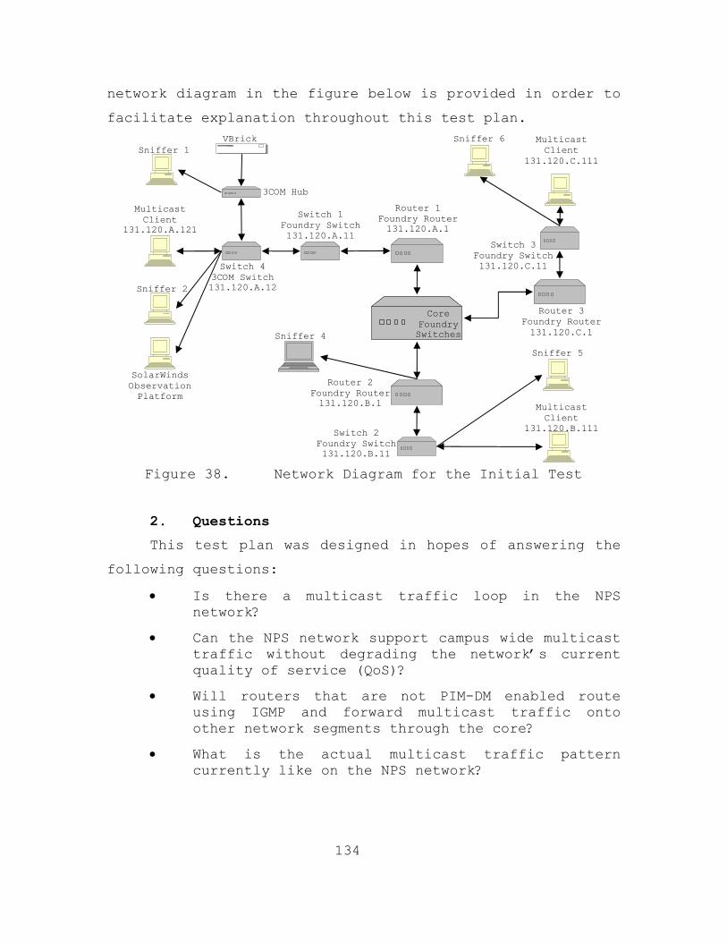
134
network diagram in the figure below is provided in order to
facilitate explanation throughout this test plan.
Figure 38. Network Diagram for the Initial Test
2. Questions
This test plan was designed in hopes of answering the
following questions:
• Is there a multicast traffic loop in the NPS network?
• Can the NPS network support campus wide multicast traffic without degrading the network’s current quality of service (QoS)?
• Will routers that are not PIM-DM enabled route using IGMP and forward multicast traffic onto other network segments through the core?
• What is the actual multicast traffic pattern currently like on the NPS network?
Switch 1 Foundry Switch 131.120.A.11
Sniffer 4
Multicast Client
131.120.B.111
VBrick
Switch 4 3COM Switch 131.120.A.12
3COM Hub
Multicast Client
131.120.A.121
Sniffer 1
Sniffer 2
Router 3 Foundry Router131.120.C.1
Multicast Client
131.120.C.111
Sniffer 6
Sniffer 5
SolarWinds Observation Platform
Router 1 Foundry Router 131.120.A.1
Router 2 Foundry Router131.120.B.1
Core Foundry Switches
Switch 3 Foundry Switch 131.120.C.11
Switch 2 Foundry Switch 131.120.B.11
135
3. Test Plan Schedule
This project plan will be executed during the NPS two
week summer break period, which starts on June 23, 2003 and
ends on July 07, 2003. The exact test date is June 30, 2003
while the actual timeframes for the testing procedure are
as follows: 4 hour (0800-1200) for test preparation - see
section 6a, 2 hours (1300-1500) for testing (testing will
only be conducted for 1 hour (1330-1430) during this 2 hour
block - see section 6b), and 1 hour for test wrap-up - see
section 6c.
4. Participants
• Lonna Sherwin (NPS NOC)
• JP Pierson (NPS NOC)
• Lary Moore and/or Mike Nichols (NPS Code 05)
• LT Christopher V. Quick (NPS Thesis Student)
5. Materials List
The following materials were used during this
experiment:
• The NPS network (see the figure in section 1)
• Six packet capture computers (sniffers) connected into the NPS network at strategic locations (can be laptops or desktop with Ethereal, EtherPeek, etc. on them).
• The Code 05 VBrick - setup to capture video from a VCR and transmit a single multicast stream.
• One VCR to provide video capture content (a Microsoft Video) to the VBrick via an RCA connection.
• Three multicast client computer with VBrick’s StreamPlayer installed – one in each designated
136
LAN segment (131.120.A.1, 131.120.B.1, and 131.120.C.1) to receive the multicast session.
• One computer running SolarWinds, configures to monitor all hub, switches, and routers in the network.
6. Test Procedure
This test plan has been broken down into three parts
in order to ensure that the integrity of the network is not
compromised. The Preparation section contains all the steps
required to be completed before the tangible test is
started, the Testing section contains the actual test
procedure, and the Wrap-up section contains all steps
needed to put the network back in its pre-test
configuration.
a. Preparation steps
NOTE: These steps will be performed from 0800 to
1200 on 30 JUN 03.
• Install the VBrick StreamPlayer on computers in the 131.120.A.1 and 131.120.B.1 segments. It will also be installed on a machine in the 131.120.C.1 segment; this segment is not multicast enabled.
• Connect sniffers to the hub on the .A network segment and to a data port on the 131.120.A.11 switch.
• Setup a port on the 131.120.B.1 router to mirror all traffic from the core switch connection trunk.
• Connect the core sniffer to the mirrored data port on the 131.120.B.1 router.
• Change the IP address of the sniffer so that it is a member of the 131.120.B.1 segment.
• Configure the sniffer on the 131.120.B.1 router to capture all multicast traffic entering and exiting the router on the core trunk.

137
• Connect the VCR to the VBrick and setup the VBrick to multicast video captured from the VCR.
• Place the video tape into the VCR and ensure that it is rewound.
b. Test Steps
NOTE: The time period for this test is 1300-1500,
actual testing is scheduled from 1330 to 1430. Completion
of the fifth bullet in this section constituted the
beginning of the 1 hour test period. It is important to
note that if at any time the network begins to experience
problems or QoS is severely impaired, the multicast
sessions will be stopped at once and all data to that point
will be evaluated to determine the problem.
• At time 1320 start packet capture on the core sniffer and capture ALL core traffic for 10 second. Save the capture to a file.
• At time 1325 start the VBrick StreamPlayer application on the client computer attached to the 131.120.A.1, 131.120.B.1, and 131.120.C.1 segments.
• At time 1330 restart packet capture on core sniffer with the multicast packet filter in place.
• At time 1330 start playing the tape in the VCR.
• At time 1330 connect the VBrick to the 131.120.A.1 network segment.
• At each client, see if the VBrick multicast group can be seen and join the session when/if a session announcement is received.
• Note CPU usage of the 131.120.A.1, 131.120.B.1, and 131.120.C.1 routers during the one hour time period.
• At all clients continue observing the session or attempting to get the session for one hour timeframe.
138
• When the 1 hour time frame is complete, disconnect the VBrick from the network.
c. Wrap-up
NOTE: At the conclusion of the 1 hour test ensure
that the following events occur.
• Close the VBrick StreamPlayer application on all clients.
• Stop packet capture on all other sniffers and save all data files. Name them for the network segment the data was collected on.
• Stop packet capture on the core sniffer and save the data file named for the core.
• Disconnect sniffer from 131.120.B.1 router.
• Reconfigure the mirrored router port on the 131.120.B.1 router for normal operation.
• Reconfigure core sniffer’s IP address for normal operation.
• Remove VBrick StreamPlayer software from systems where it is no longer needed.
7. Desired Outcome
It is hoped that this test will provide data that may
enable multicast broadcast to become a reality at NPS.
Finding that multicast works, without error, on the new
backbone or to find a correctable problem is the primary
goal of this test. All data and findings of this test will
be provided to the NOC and Code 05 before being released
for any other purposes.
B. MULTICAST NETWORK TEST PLAN (FINAL)
The Test Plan below was used during the
Clarification/Load and Stress tests. Its purpose was to

139
coordinate the efforts of all personnel involved in the
test, ensure that all necessary safety measures were
followed, and all equipment was returned to its pretest
state.
1. Test Plan Introduction
This test plan was developed to facilitate an
examination of the NPS networks ability to handle
multicast, various multicast protocols, and multiple
multicast broadcast streams. The author of this thesis and
personnel from the NOC utilized the materials listed in
section 3 to perform the test procedure in section 4. This
plan was developed in order to gather multicast routing
traffic and stream data for evaluation and analysis as part
of this thesis project. The network diagram in Figure 12
below is provided in order to facilitate explanation
throughout this test plan.
2. Questions
Questions are the fundamental reason behind every test
plan and this one was designed in order to answer the
questions indicated in the subsections above. If this test
plan is being used for further research in the area of
multicast, the questions that need to be answer go here.
3. Test Plan Schedule
The execution of this test plan took place in the
timeframe indicated in the subsections above. If this test
plan is being used for further research in the area of
140
multicast, the actual timeframe of the test need to go
here.
4. Materials List
The following materials were used during this
experiment:
• The NPS network (see the figures in the subsections above)
• One packet capture computer (sniffer) connected to the core switches of the NPS network (a laptop running Ethereal)
• One computer running SolarWinds, configures to monitor all hub, switches, and routers in the network
• The Code 05 VBrick - setup to transmit a multicast stream from a VCR.
• One VCR to provide video capture content (a Microsoft Video) to the VBrick via an RCA connection.
• A Windows 2000 server running VBrick Systems, StreamPump version 2.1.0
• Multiple .mov files to stream via the server (one for each stream is required)
• One computer with VBrick’s StreamPlayer installed.
5. Test Procedure
This test plan was broken down into three parts in
order to ensure that the integrity of the network was not
compromised. The Preparation section contains all the steps
required to be completed before the tangible test was
started. These steps were performed on July 17, 2003 from
1400 to 1500 and on July 18, 2003 from 0800 to 0900. The
Test Steps section contains the actual steps for the test.
Those steps were performed on July 18, 2003 from 0930 to
141
1030. The Wrap-up steps contain all the actions needed to
put the network back in its pre-test configuration. Those
steps were performed on July 18, 2003 from 1030 to 1130.
a. Preparation Steps
• Install the VBrick StreamPlayer on a computer connected to the 131.120.B.1 segment.
• Setup a port on the 131.120.B.1 router to mirror all traffic from the core switch.
• Connect the core sniffers to the mirrored data port on the 131.120.B.1 router.
• Change the IP address of the sniffer so that it is a member of the 131.120.B.1 segment.
• Connect the VCR to the VBrick and setup the VBrick to multicast video captured from the VCR.
• Configure a sniffer port on the 131.120.B.1 router to mirror all data entering and exiting the router on the core trunk.
b. Test Steps
Completion of the fifth bullet in this section
constituted the beginning of the 1 hour test period. It is
important to note that if at any time the network begins to
experience problems or QoS is severely impaired, the
multicast sessions will be stopped at once and all data to
that point will be evaluated to determine the problem.
• Connect the sniffer to the sniffer port and use it to capture all core traffic for 10 second. Save the capture to a file.
• Restart packet capture on core sniffer with the multicast packet filter in place.
• Start the VBrick StreamPlayer application on the client computer attached to the 131.120.B.1 segment.
• Start playing the media in the VCR.

142
• Connect the VBrick to the 131.120.A.1 network segment.
• At the client, join the VBrick session when a channel announcement is received.
• At the multicast server, starts a new multicast stream every five minutes until a total of seven streams are being transmitted.
• Use the client to join each multicast session at they appear on the VBrick StreamPlayer application.
• Note CPU usage of the 131.120.A.1 and 131.120.B.1 Routers as the new session are introduced and monitor the network closely during this time period.
• At the client, periodically switch between each session for the remainder of the 1 hour timeframe.
• When the 1 hour time frame is complete shut down the multicast streams from the server one at a time.
• Disconnect the VBrick from the network.
c. Wrap-up
• Close the VBrick StreamPlayer application on the client.
• Stop packet capture on the core sniffer and save the data file.
• Disconnect sniffer from 131.120.B.1 router.
• Reconfigure the mirrored router port on the 131.120.B.1 router for normal operation.
• Reconfigure sniffer’s IP address for normal operation.
6. Desired Outcome
It was hoped that multicast would work, without error,
on the new network backbone or a correctable configuration

143
problem would be found. This test was designed to provide
data that would allow multicast to be enable throughout the
entire NPS network so that multicast media to become a
reality at NPS. Finally, all the data and findings from
this test have been provided to the NOC and Code 05 before
being released in this document.

144
THIS PAGE INTENTIONALLY LEFT BLANK
145
APPENDIX C: AUTOMATED PACKET CAPTURE
Capturing network traffic over an extended period can
be performed by Ethereal as long as it is a continuous
capture session. Ethereal also allows the user to capture
during a specific time period as long as the user is
present to initial the process. But for the twenty-four
hour test, captures were to be performed every half hour
for five minute. A capture of the entire packet flow and
after that a five minute capture of the network traffic
with the multicast filter in place. This would not be
possible with Ethereal unless it was done manually.
To get around this limitation in Ethereal, the
Tethereal application, .bat files, and the Windows Task
Scheduler were used. Tethereal is part of the Ethereal
installation and is a text driven version of Ethereal’s
packet capture process. Using the .bat files to initiate
the process allowed the capture file name to be altered
every time a new capture was started. The three .bat files
used during the Stress test are listed below. LongCaptureM-
Cast.bat initiated a multicast filter network traffic
capture for an hour, Capture.bat was used to initial an
entire flow capture for five minutes, and CaptureM-Cast.bat
initiated a five minute capture of the multicast filtered
network traffic.
Using these .bat files, it was possible to setup tasks
in the Windows Task Scheduler to execute them every thirty
minutes. Thus providing an automated the periodic capture
of network traffic throughout a twenty-four hour period.
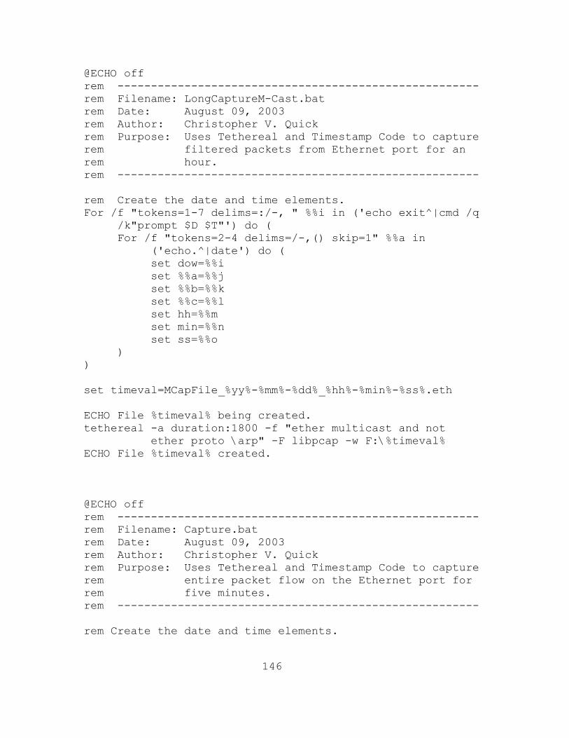
146
@ECHO off rem ------------------------------------------------------ rem Filename: LongCaptureM-Cast.bat rem Date: August 09, 2003 rem Author: Christopher V. Quick rem Purpose: Uses Tethereal and Timestamp Code to capture rem filtered packets from Ethernet port for an rem hour. rem ------------------------------------------------------ rem Create the date and time elements. For /f "tokens=1-7 delims=:/-, " %%i in ('echo exit^|cmd /q
/k"prompt $D $T"') do ( For /f "tokens=2-4 delims=/-,() skip=1" %%a in
('echo.^|date') do ( set dow=%%i set %%a=%%j set %%b=%%k set %%c=%%l set hh=%%m set min=%%n set ss=%%o ) ) set timeval=MCapFile_%yy%-%mm%-%dd%_%hh%-%min%-%ss%.eth ECHO File %timeval% being created. tethereal -a duration:1800 -f "ether multicast and not
ether proto \arp" -F libpcap -w F:\%timeval% ECHO File %timeval% created. @ECHO off rem ------------------------------------------------------ rem Filename: Capture.bat rem Date: August 09, 2003 rem Author: Christopher V. Quick rem Purpose: Uses Tethereal and Timestamp Code to capture rem entire packet flow on the Ethernet port for rem five minutes. rem ------------------------------------------------------ rem Create the date and time elements.
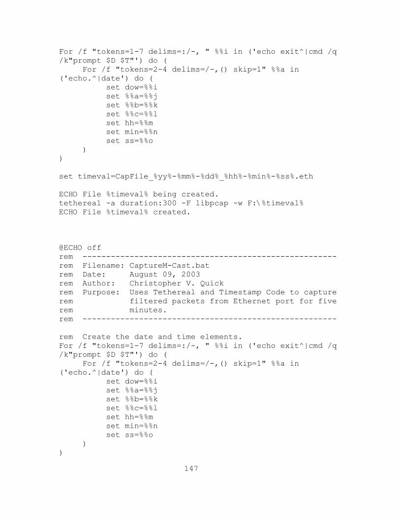
147
For /f "tokens=1-7 delims=:/-, " %%i in ('echo exit^|cmd /q /k"prompt $D $T"') do ( For /f "tokens=2-4 delims=/-,() skip=1" %%a in ('echo.^|date') do ( set dow=%%i set %%a=%%j set %%b=%%k set %%c=%%l set hh=%%m set min=%%n set ss=%%o ) ) set timeval=CapFile_%yy%-%mm%-%dd%_%hh%-%min%-%ss%.eth ECHO File %timeval% being created. tethereal -a duration:300 -F libpcap -w F:\%timeval% ECHO File %timeval% created. @ECHO off rem ------------------------------------------------------ rem Filename: CaptureM-Cast.bat rem Date: August 09, 2003 rem Author: Christopher V. Quick rem Purpose: Uses Tethereal and Timestamp Code to capture rem filtered packets from Ethernet port for five rem minutes. rem ------------------------------------------------------ rem Create the date and time elements. For /f "tokens=1-7 delims=:/-, " %%i in ('echo exit^|cmd /q /k"prompt $D $T"') do ( For /f "tokens=2-4 delims=/-,() skip=1" %%a in ('echo.^|date') do ( set dow=%%i set %%a=%%j set %%b=%%k set %%c=%%l set hh=%%m set min=%%n set ss=%%o ) )

148
set timeval=MCapFile_%yy%-%mm%-%dd%_%hh%-%min%-%ss%.eth ECHO File %timeval% being created. tethereal -a duration:300 -f "ether multicast and not ether
proto \arp" -F libpcap -w F:\%timeval% ECHO File %timeval% created.

149
LIST OF REFERENCES
[01] ODUSD(R), Readiness and Training, “Department of
Defense Strategic Plan for Advanced Distributed Learning” [http://www.maxwell.af.mil/au/afiadl/plans&policy/pdfs/dodstratplan.pdf] August 2003
[02] Director of Naval Training (N7), “The Navy-Wide
Distributed Learning Planning Strategy” [https://www.cnet.navy.mil/cnet/Trn_tech/DL/final1.pdf] August 2003
[03] Ko, Susan and Rossen, Steve, College Teaching Series:
Teaching Online-A Practical Guide, Houghton Mufflin, 2001
[04] Seneca College, “Distance Learning”
[http://cdl.senecac.on.ca/Prospective/Intro/dl.html] June 2003
[05] Intelligraphics Inc., “IP-Multicasting Technology Part
1: History and Overview” [http://www.intelligraphics.com/articles/ipmulticasting1_article.html] August 2003
[06] IANA, “INTERNET MULTICAST ADDRESSES”
[http://www.iana.org/assignments/multicast-addresses] July 2003
[07] Meyer D. and Lothberg P., “RFC-2770: GLOP Addressing
in 233/8”, [http://www.faqs.org/rfcs/rfc2770.html] July 2003
[08] Huston, Geoff, “Autonomous System Number-to-Name
Mapping” [http://bgp.potaroo.net/cidr/autnums.html] June 2003
[09] Black, Darryl P., Building Switched Networks, pp. 193-
209, Addison-Wesley, 1999 [10] Miller, C. Kenneth, Multicast Networking and
Applications, Addison-Wesley, 1998

150
[11] Edwards, Brian M., Giuliano, Leonard A., Wright, Brian R., Interdomain Multicast Routing, pp. 109-120, Addison-Wesley, 2002
[12] Handley, M. and Perkins, C. and Whelan, E., “RFC-2974:
Session Announcement Protocol” [http://www.faqs.org/rfcs/rfc2974.html] June 2003
[13] Handley, M. and Jacobson, V., “RFC-2327: SDP: Session
Description Protocol” [http://www.faqs.org/rfcs/rfc2327.html] July 2003
[14] Deering S., “RFC-1112: Host Extensions for IP
Multicasting” [http://www.faqs.org/rfcs/rfc1112.html] July 2003
[15] Fenner, W., “RFC-2236: Internet Group Management
Protocol, Version 2” [http://www.faqs.org/rfcs/rfc2236.html] July 2003
[16] Cain, B., Deering, S., Kouvelas, I., Fenner, B.,
Thyagarajan, A., “RFC-3376: Internet Group Management Protocol, Version 3” [http://www.faqs.org/rfcs/rfc3376.html] June 2003
[17] Tseng, Mickey, “IGMP Snooping”
[http://www.zyxel.com/support/supportnote/ves1012/app/igmpsnoop.htm] July 2003
[18] Intelligraphics Inc., “IP-Multicasting Technology Part
3: Protocol Timing, Sizing and Decoding” [http://www.intelligraphics.com/articles/ipmulticasting3_article.html] August 2003
[19] Waitzman, D. and Partridge, C. and Deering S., “RFC-
1075: Distance Vector Multicast Routing Protocol” [http://www.faqs.org/rfcs/rfc1075.html] August 2003
[20] Ross, Keith W. and Kurose, Jim “Computer Networking: A
Top-Down Approach Featuring the Internet” [http://cosmos.kaist.ac.kr/cs441/text/Contents.htm] August 2003
[21] Guzules, Amy, “SuperStack Switch Management Guide”
http://support.3com.com/infodeli/tools/switches/ss3/management/ug/mlticast.htm August 2003

151
[22] Foundry Networks, Foundry switch and Router
Installation and Basic Configuration Guide, May 2002 [23] Bhattacharyya, S., “FRC-3569: An Overview of Source-
Specific Multicast (SSM)” [http://www.faqs.org/rfcs/rfc3569.html] June 2003

152
THIS PAGE INTENTIONALLY LEFT BLANK

153
INITIAL DISTRIBUTION LIST
Defense Technical Information Center Ft. Belvoir, VA
Dudley Knox Library Naval Postgraduate School Monterey, CA
Chairman, Code 32 Naval Postgraduate School Monterey, CA
Professor Geoffrey Xie, Code 32 Naval Postgraduate School Monterey, CA
Lonna Sherwin, NOC Naval Postgraduate School Monterey, CA
Brian Steckler Naval Postgraduate School Monterey, CA
Joe Lopiccolo, Code 05
Naval Postgraduate School Monterey, CA
Vince Darago
Naval Postgraduate School Monterey, CA
Lary Moore, Code 05
Naval Postgraduate School Monterey, CA
Mike Nichols, Code 05
Naval Postgraduate School Monterey, CA
LT Christopher V. Quick
Naval Information Warfare Activity (NIWA) Ft. George G. Meade, MD