pim dense mode‘adások... · • pim dense mode grafting • pim graft messages are used to...
TRANSCRIPT

1Module3.pptCopyright ? ?1998-2001, Cisco Systems, Inc.
1Module3. ppt ©1998 – 2001, Cisco Systems, Inc. All rights reserved. 8/10/2001 11:41 AM
PIM Dense ModeModule 3

2Module3.pptCopyright ? ?1998-2001, Cisco Systems, Inc.
Module3. ppt ©1998 – 2001, Cisco Systems, Inc. All rights reserved. 2228/10/2001 11:41 AM
Module Objectives
• Identify and explain the basic mechanisms of PIM Dense Mode.
• Identify the packet types used by PIM Dense Mode.
• Configure and verify normal PIM DM operation.

3Module3.pptCopyright ? ?1998-2001, Cisco Systems, Inc.
3
Module3. ppt ©1998 – 2001, Cisco Systems, Inc. All rights reserved. 3338/10/2001 11:41 AM
GeekometerModule Agenda
• PIM Dense Mode Overview• PIM Packet Formats• PIM Dense Mode Concepts• PIM Dense Mode Review• Configuring PIM Dense-Mode

4Module3.pptCopyright ? ?1998-2001, Cisco Systems, Inc.
Module3. ppt ©1998 – 2001, Cisco Systems, Inc. All rights reserved. 4448/10/2001 11:41 AM
PIM Dense Mode Overview
• Uses “Push” Model– Traffic is initially flooded to all PIM neighbors– Branches that don’t want data are pruned
• Multicast forwarding state is created by the arrival of data
• If the source goes inactive, the tree is torn down
• The PIM Dense Mode “Push” Model• This model assumes that there are members at all points in the network, hence
the concept of a “dense” distribution of receivers.
• Routers initially flood Multicast traffic out all interfaces where there is:
– Another PIM-DM neighbor or
– A directly connected member or
– An interface that has been manually configured to join the group.
• Branches that do not have members send Prune messages toward the source to prune off the unwanted/unnecessary traffic. These pruned branches timeout after 3 minutes and traffic is re-flooded down the branch.
• Due to this periodic re-flooding, dense mode is more applicable when bandwidth is plentiful as bandwidth is wasted due to re-flooding.
• In Dense mode, multicast state is created by data arrival• In PIM Dense mode, the control plane and the data plane are one in the same.
This implies the following:
– (S, G) state, and hence the Source Tree, is created “on the fly” by the arrival of (S, G) multicast traffic.
– (S, G) state, and hence the Source Tree, is deleted when the source goes inactive and no multicast traffic is received by the router for 3 minutes.
• Because the control plane and data plane are mixed in PIM Dense mode, its maintenance of the Source Tree is considerably less deterministic than Sparse mode. This can sometimes result in instabilities and temporary loss of data during some network topology changes.
• Dense mode only has source trees - no shared trees are used

5Module3.pptCopyright ? ?1998-2001, Cisco Systems, Inc.
Module3. ppt ©1998 – 2001, Cisco Systems, Inc. All rights reserved. 5558/10/2001 11:41 AM
PIM Dense Mode Overview
• Grafts are used to join existing source tree• Asserts are used to determine forwarder
for multi-access LAN• Prunes are sent on non-RPF P2P links
– Asserts are sent on non-RPF multi-access links
• Rate-limited prunes are sent on all P2P links
• PIM Dense Mode Grafting• PIM Graft messages are used to reduce the join latency when a previously
pruned branch of the Source Tree must be “grafted” back. This can be the case when a member joins the group after the router has sent a Prune message to prune off unwanted traffic.
• If Grafts were not used, the member would have to wait up to three minutes for the periodic re-flooding to occur to begin receiving the multicast traffic. By using Grafts, the Prune can be reversed almost immediately.
• PIM Dense Mode Asserts• When two routers both forward the same (S, G) multicast traffic onto a common
multi-access LAN, duplicate traffic is generated. When this occurs, Assert messages are generated by both routers to determine which router should continue forwarding on the LAN and which router(s) should stop (prune).
• PIM Dense Mode Pruning• When data arrives on non-RPF interface (i.e. an interface that is not used to
reach the source) and the interface is point-to-point (P2P), a Prune is immediately sent to the upstream neighbor in an attempt to shut off the flow of traffic.
– Note that when data arrives on a non-RPF interface that is not a P2P (i.e. multi-access) interface, an Assert is triggered instead of a Prune.
• Rate-limited Prunes are sent on all P2P interfaces.
– This means that if data continues to arrive on a non-RPF, P2P interface, rate-limited Prunes are sent.
– Rate-limited Prunes are also sent on the RPF interface of P2P links when it is necessary to Prune the flow of traffic.

6Module3.pptCopyright ? ?1998-2001, Cisco Systems, Inc.
Module3. ppt ©1998 – 2001, Cisco Systems, Inc. All rights reserved. 6668/10/2001 11:41 AM
PIM Dense Mode Overview
Source
Initial Flooding
Receiver
(S, G) State created inevery every router in the network!Multicast Packets
• Initial Flooding• In this example, multicast traffic being sent by the source is flooded throughout
the entire network.
• As each router receives the multicast traffic via its RPF interface (the interface in the direction of the source), it forwards the multicast traffic to all of its PIM-DM neighbors.
• Note that this results in some traffic arriving via a non-RPF interface such as the case of the two routers in the center of the drawing. (Packets arriving via the non-RPF interface are discarded.) These non-RPF flows are normal for the initial flooding of data and will be corrected by the normal PIM-DM pruning mechanism.

7Module3.pptCopyright ? ?1998-2001, Cisco Systems, Inc.
Module3. ppt ©1998 – 2001, Cisco Systems, Inc. All rights reserved. 7778/10/2001 11:41 AM
PIM Dense Mode Overview
Source
Pruning unwanted traffic
Receiver
Prune Messages
Multicast Packets
• Pruning unwanted traffic• In the example above, PIM Prunes (denoted by the dashed arrows) are sent to
stop the flow of unwanted traffic.
• Prunes are sent on the RPF interface when the router has no downstream members that need the multicast traffic.
• Prunes are also sent on non-RPF interfaces to shutoff the flow of multicast traffic that is arriving via the wrong interface (i.e. traffic arriving via an interface that is not in the shortest path to the source.)
– An example of this can be seen at the second router from the receiver near the center of the drawing. Multicast traffic is arriving via a non-RPF interface from the router above (in the center of the network) which results in a Prune message.

8Module3.pptCopyright ? ?1998-2001, Cisco Systems, Inc.
Module3. ppt ©1998 – 2001, Cisco Systems, Inc. All rights reserved. 8888/10/2001 11:41 AM
PIM Dense Mode Overview
Results after Pruning
Source
Receiver
Flood & Prune processFlood & Prune processrepeats every 3 minutes!!!repeats every 3 minutes!!!
(S, G) State still exists inevery every router in the network!Multicast Packets
• Results after Pruning• In the final drawing in our example shown above, multicast traffic has been
pruned off of all links except where it is necessary. This results in a Shortest Path Tree (SPT) being built from the Source to the Receiver.
• Even though the flow of multicast traffic is no longer reaching most of the routers in the network, (S, G) state still remains in ALL routers in the network. This (S, G) state will remain until the source stops transmitting.
• In PIM-DM, Prunes expire after three minutes. This causes the multicast traffic to be re-flooded to all routers just as was done in the “Initial Flooding” drawing. This periodic (every 3 minutes) “Flood and Prune” behavior is normal and must be taken into account when the network is designed to use PIM-DM.

9Module3.pptCopyright ? ?1998-2001, Cisco Systems, Inc.
Module3. ppt ©1998 – 2001, Cisco Systems, Inc. All rights reserved. 9998/10/2001 11:41 AM
PIM Packet Formats
• PIM Packet Headers• PIM Hello Messages• PIM Join/Prunes• PIM Grafts/Graft Acks• PIM Asserts

10Module3.pptCopyright ? ?1998-2001, Cisco Systems, Inc.
Module3. ppt ©1998 – 2001, Cisco Systems, Inc. All rights reserved. 1010108/10/2001 11:41 AM
PIM Packet Formats (SM Only)
• PIM Registers• PIM Register-Stop

11Module3.pptCopyright ? ?1998-2001, Cisco Systems, Inc.
Module3. ppt ©1998 – 2001, Cisco Systems, Inc. All rights reserved. 1111118/10/2001 11:41 AM
PIMv1 Packet Header
Type:0x14 = PIM Message
Code:0 = Router-Query1 = Register (SM only)2 = Register-Stop (SM only)3 = Join/Prune4 = RP-Reachibility (SM only)5 = Assert6 = Graft7 = Graft-ACK
Ver:PIM Version = 1
PIMv1 used IGMP Packets
7 15 313
Code Checksum
Ver.
Type
Reserved
• PIMv1 messages are multicast to the ALL-Routers (224.0.0.2) group with a TTL of 1.
Note: (PIMv1 packet formats are not shown. Only PIMv2 packets will be given.)
• PIM (v1) Packet Headers• An IGMP type code of 0x14 indicates the frame is carrying a PIMv1 message -
the code field then determines the type of PIM messages.
– PIMv1 messages are multicast to the ALL-Routers (224.0.0.2) multicast group address with a TTL of 1. This means that these control messages are Link-Local in scope.

12Module3.pptCopyright ? ?1998-2001, Cisco Systems, Inc.
Module3. ppt ©1998 – 2001, Cisco Systems, Inc. All rights reserved. 1212128/10/2001 11:41 AM
PIMv2 Packet Header
Ver:PIM Version = 2
Type:0 = Hello1 = Register (SM only)2 = Register-Stop (SM only)3 = Join/Prune4 = Bootstrap (SM BSR only)5 = Assert6 = Graft (DM only)7 = Graft-Ack (DM only)8 = C-RP-Announcement (SM BSR only)
PIMv2 is assigned protocol number 103317 153
Ver. Type Reserved Checksum
• PIMv2 messages are multicast to the ALL-PIM-Routers (224.0.0.13) group with a TTL of 1.
• PIM (v2) Packet Headers• PIMv2 packets are encoded in their own protocol packets using PIM assigned
protocol number of 103. The Type field then determines the type of PIMv2 message.
– PIMv2 messages are multicast to the ALL-PIM-Routers (224.0.0.13) multicast group address with a TTL of 1. This means that these control messages are Link-Local in scope.

13Module3.pptCopyright ? ?1998-2001, Cisco Systems, Inc.
Module3. ppt ©1998 – 2001, Cisco Systems, Inc. All rights reserved. 1313138/10/2001 11:41 AM
PIM Hello Messages
Option Types:1 = Holdtime (Period of time in seconds before this PIM
neighbor times out.)19 = DR Priority20 = Generation ID
317 153
Ver. Type Reserved Checksum
Option LengthOption Type
Option Value
OptionLengthOption Type
OptionValue
. . .
• PIMv2 Hello Messages• PIMv2 Hello messages are used to form and maintain neighbor adjacencies
– They are sent periodically to indicate to the other PIM routers on the network that this PIM router is still present.
• The PIMv2 Hello message format defines numerous Option TLV’s which include:
– Holdtime: This specifies the time in seconds that this neighbor is reachable. A value of 0xffff indicates the neighbor never times out. A value of 0x0000 means the neighbor is immediately timed out.
– DR Priority: This value can be used in the election of the DR for the subnet.
– Generation ID: This is a random 32-bit value that is sent whenever the neighbor actives PIM on the interface. It can be used to determine when the neighbor has been reactivated after a failure.
14Module3.pptCopyright ? ?1998-2001, Cisco Systems, Inc.
Module3. ppt ©1998 – 2001, Cisco Systems, Inc. All rights reserved. 1414148/10/2001 11:41 AM
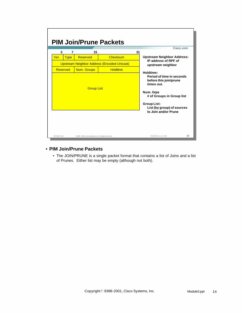
PIM Join/Prune Packets
Upstream Neighbor Address:IP address of RPF ofupstream neighbor
Holdtime:Period of time in secondsbefore this join/prunetimes out.
Num. Grps# of Groups in Group list
Group List:List (by group) of sourcesto Join and/or Prune
317 153
Ver. Type Reserved Checksum
Upstream Neighbor Address (Encoded-Unicast)
Reserved Num. Groups Holdtime
Group List
• PIM Join/Prune Packets• The JOIN/PRUNE is a single packet format that contains a list of Joins and a list
of Prunes. Either list may be empty (although not both).

15Module3.pptCopyright ? ?1998-2001, Cisco Systems, Inc.
• Group Lists• Group Lists are used in Join/Prune messages as well as Graft and Graft -Ack
messages.
• A Group List is a list of Group entries each beginning with a Group IP Address and Group mask to identify the Multicast Group.
• Each Group List entry contains a list of zero or more sources to Join followed by a list of zero or more sources to Prune.
– Group IP Address
– Number of Join Sources
– Number of Prune Sources
– Join List
– Prune List
• The addresses used in Join and Prune lists use a special encoded format that allows for other protocols besides IPv4. (See next slides.)
Module3. ppt ©1998 – 2001, Cisco Systems, Inc. All rights reserved. 1515158/10/2001 11:41 AM
PIM Group Lists
Group-xGroup IP Address
Number of Join Sources# of Joins for Group-x
Number of Prune Sources# of Prunes for Group-x
Join/Prune Source -xEncoded Source address tobe Joined/Pruned
15 310
Group-1 (Encoded-Group)
Number of Join Sources Number of Prune Sources
Join Source-1 (Encoded-Source)
Join Source-n (Encoded-Source)
Prune Source-1 (Encoded-Source)
Prune Source-n (Encoded-Source)
Group-2 (Encoded-Group)
Number of Join Sources Number of Prune Sources
• Group Lists are used in Join/Prune and Graft/Graft-Ack messages.
16Module3.pptCopyright ? ?1998-2001, Cisco Systems, Inc.
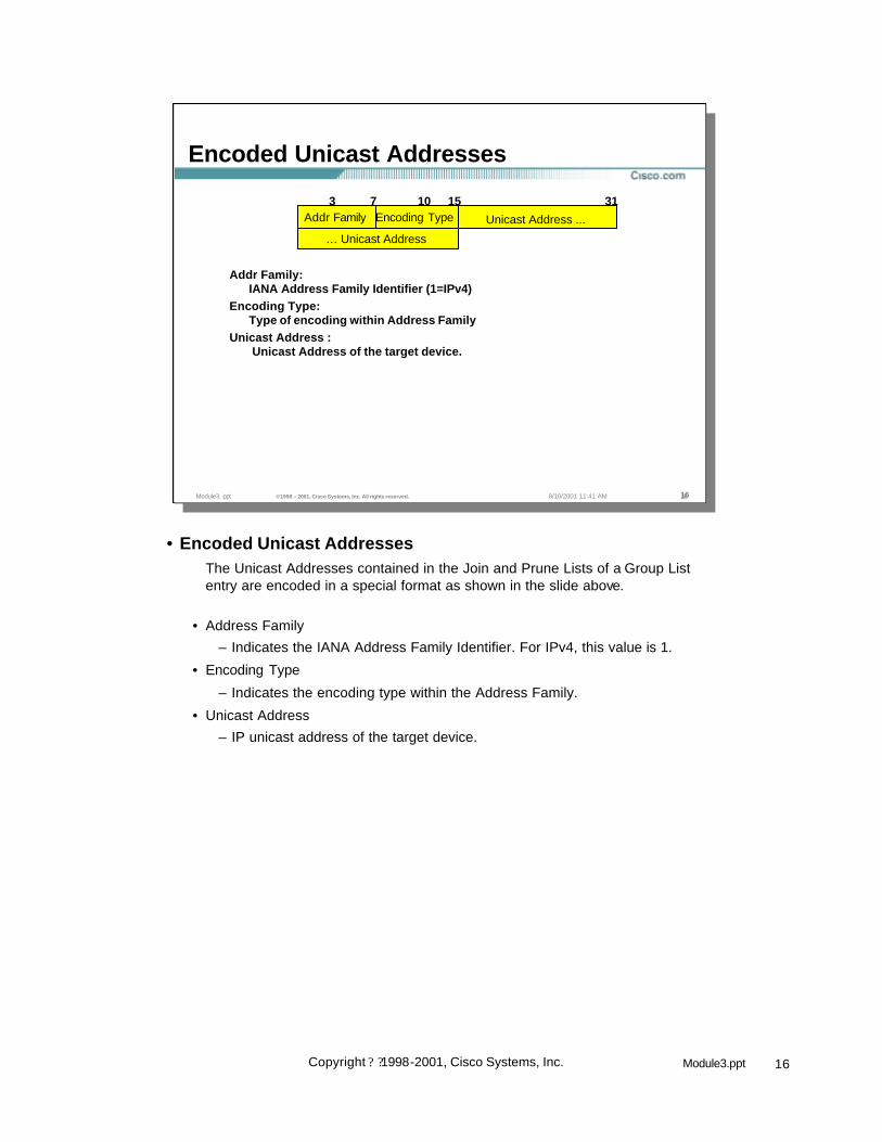
• Encoded Unicast AddressesThe Unicast Addresses contained in the Join and Prune Lists of a Group List entry are encoded in a special format as shown in the slide above.
• Address Family
– Indicates the IANA Address Family Identifier. For IPv4, this value is 1.
• Encoding Type
– Indicates the encoding type within the Address Family.
• Unicast Address
– IP unicast address of the target device.
Module3. ppt ©1998 – 2001, Cisco Systems, Inc. All rights reserved. 1616168/10/2001 11:41 AM
Encoded Unicast Addresses
Addr Family:IANA Address Family Identifier (1=IPv4)
Encoding Type:Type of encoding within Address Family
Unicast Address :Unicast Address of the target device.
7 15 313
Unicast Address ...
… Unicast Address
Addr Family10
Encoding Type

17Module3.pptCopyright ? ?1998-2001, Cisco Systems, Inc.
• Encoded Source AddressesThe Source Addresses contained in the Join and Prune Lists of a Group List entry are encoded in a special format as shown in the slide above.
• Address Family
– Indicates the IANA Address Family Identifier. For IPv4, this value is 1.
• Encoding Type
– Indicates the encoding type within the Address Family.
• S = Sparse Mode bit
– Used by routers on the Shortest-Path Tree (SPT) to indicate the group is a sparse mode group which tells the receiver of this join that it must send periodic Joins toward the source.
• W = Wildcard bit
– Indicates that the Join/Prune applies to the (*, G) entry. If this bit is cleared, it indicates that this applies to an (S, G) entry. Joins and Prunes sent to the RP should have this bit set.
• R = RP bit
– Indicates that this information should be sent up the Shared Tree towards the RP. If this bit is clear, the information should be sent up the Shortest-Path Tree toward the source.
• M. Len
– Mask length in bits.
• Source Address
– IP address of the Source.
Module3. ppt ©1998 – 2001, Cisco Systems, Inc. All rights reserved. 1717178/10/2001 11:41 AM
Encoded Source Addresses
Addr Family:IANA Address Family Identifier (1=IPv4)
Encoding Type:Type of encoding within Address Family
S = Sparse Mode bit :Indicates sparse mode group. Rcvrs must send periodic joins.
W = Wildcard bit :Indicates join/prune applies to (*, G) entry.
R = RP bit :Indicates this join/prune should be sent up the Shared Tree towards the RP.
Mask Length:Number of bits in the prefix of the Group Address.
Source Address :Address of Multicast Source.
7 15 313
Source Address …
10Mask Len
23RsvdEncoding TypeAddr. Family S W R

18Module3.pptCopyright ? ?1998-2001, Cisco Systems, Inc.
• Encoded Group AddressesGroup Addresses contained in the Join and Prune Lists of a Group List entry are encoded in a special format as shown in the slide above.
• Address Family
– Indicates the IANA Address Family Identifier. For IPv4, this value is 1.
• Encoding Type
– Indicates the encoding type within the Address Family.
• M. Len
– Mask length in bits.
• Group Address
– IP multicast group address.
Module3. ppt ©1998 – 2001, Cisco Systems, Inc. All rights reserved. 1818188/10/2001 11:41 AM
Encoded Group Addresses
7 15 313
Group Address …
10Mask Len
23ReservedEncoding TypeAddr. Family
Addr Family:IANA Address Family Identifier (1=IPv4)
Encoding Type:Type of encoding within Address Family
Mask Length:Number of bits in the prefix of the Group Address.
Group Address :Multicast Group Address.

19Module3.pptCopyright ? ?1998-2001, Cisco Systems, Inc.
• PIM Graft/Graft-Ack Packets• Graft/Graft-Ack are used in dense mode for grafting onto the tree
• These are the only PIM messages that are sent reliably (I.e. get an acknowledgement)
Module3. ppt ©1998 – 2001, Cisco Systems, Inc. All rights reserved. 1919198/10/2001 11:41 AM
PIM Graft/Graft-Ack Packets
Upstream Neighbor Address:IP address of RPF ofupstream neighbor
Holdtime:Period of time in secondsbefore this join/prunetimes out.
Num. Grps# of Groups in Group list
Group List:List (by group) of sourcesto Graft or Graft-Ack
317 153
Ver. Type Reserved Checksum
Upstream Neighbor Address (Encoded-Unicast)
Reserved Num. Groups Holdtime
Group List

20Module3.pptCopyright ? ?1998-2001, Cisco Systems, Inc.
Module3. ppt ©1998 – 2001, Cisco Systems, Inc. All rights reserved. 2020208/10/2001 11:41 AM
PIM Assert Packets
Group Address:Identifies Group of the Assert
Source Address:Identifies Source of the Assert
R: (Sparse Mode)1 = Assert down RP Tree; 0 = Assert Down SPT
Metric Preference:Admin. Distance of unicast routing protocol
Metric:Unicast routing protocol metric
317 153
Ver. Type Reserved Checksum
Group Address (Encoded-Group)
Source Address (Encoded-Source)
Metric PreferenceR
Metric
• PIM Assert Packets• Assert messages determine who will be the active forwarder when there is
redundancy in the network toward the source
• If the same routing protocol is used between the redundant neighbors, the metric is compared and the best metric wins
• In the case of an equal cost metric with the same routing protocol - the highest IP address neighbor will break the tie
• In the case where dissimilar unicast routing protocols are used, a metric preference is used to weight the preferred order of the routing information of each unicast routing protocol (like administrative distance)

21Module3.pptCopyright ? ?1998-2001, Cisco Systems, Inc.
Module3. ppt ©1998 – 2001, Cisco Systems, Inc. All rights reserved. 2121218/10/2001 11:41 AM
PIM Register Packets
B = Border Bit:Indicates DR is a border router performing a proxy-register
N = Null Register Bit:Indicates DR is sending a Null-Register before expiring its register-suppression timer.
Multicast Data Packet:The original packet sent by the source. For periodic sending ofregisters, this part is null.
Sparse Mode Only317 153
Ver. Type Reserved Checksum
Multicast Data Packet
ReservedB N
• PIM Register Packets• Used in SM by the DR to encapsulate multicast packets and send them to the
RP so they may be forwarded down the shared tree.
• Register messages with encapsulated multicast packets continue to be sent to the RP by the DR until a Register-Stop message is received from the RP.

22Module3.pptCopyright ? ?1998-2001, Cisco Systems, Inc.
Module3. ppt ©1998 – 2001, Cisco Systems, Inc. All rights reserved. 2222228/10/2001 11:41 AM
PIM Register-Stop PacketsSparse Mode Only
Group Address:The group address from the register message.
Source Address:IP host address of source from multicast data packet in register.
317 153
Ver. Type Reserved Checksum
Group Address (Encoded-Group)
Source Address (Encoded-Source)
• PIM Register-Stop Packets• Used in SM by the RP to inform the DR to stop sending Register messages.
This message is sent after the RP has joined the source tree to the DR and is receiving the multicast traffic natively via the SPT.

23Module3.pptCopyright ? ?1998-2001, Cisco Systems, Inc.
Module3. ppt ©1998 – 2001, Cisco Systems, Inc. All rights reserved. 2323238/10/2001 11:41 AM
PIM DM Concepts
• PIM Neighbor Discovery• PIM DM State• PIM DM Forwarding• PIM DM Pruning• PIM DM Grafting• PIM Assert Mechanism• PIM DM State Maintenance

24Module3.pptCopyright ? ?1998-2001, Cisco Systems, Inc.
Module3. ppt ©1998 – 2001, Cisco Systems, Inc. All rights reserved. 2424248/10/2001 11:41 AM
PIM Neighbor Discovery
171.68.37.2PIM-DM Router 2
Highest IP Address electedas “DR” (Designated Router)
PIM Query
PIM-DM Router 1171.68.37.1
• PIM Queries are Multicast to the “All-Routers” (224.0.0.2) (with a TTL of 1) multicast group address periodically. (Default = 30 seconds)
• If the “DR” times-out, a new “DR” is elected.
• In PIM DM, interface is added to outgoing interface list for all groupswhen first neighbor is heard.
PIM Query
• PIM Neighbor Discovery• PIM Queries are sent periodically to discover the existance of other PIM routers
on the network.
• For Multi-Access networks (e.g. Ethernet), the PIM Query message is multicast to the “All-Routers” (224.0.0.2) multicast group address.
• Designated Router (DR)• For Multi-Access networks, a Designated Router (DR) is elected. In PIM Sparse
mode networks, the DR is responsible for sending Joins to the RP for hosts on the Multi-Access network. For Dense mode, the DR has no meaning. The exception to this is when IGMPv1 is in use. In this case, the DR also functions as the IGMP Querier for the Multi-Access network.
• Designated Router (DR) Election• To elect the DR, each PIM node on a Multi-Access network examines the
received PIM Query messages from its neighbors and compares the IP Address of its interface with the IP Address of its PIM Neighbors. The PIM Neighbor with the highest IP Address is elected the DR.
• If no PIM Querys have been received from the elected DR after some period (configurable), the DR Election mechanism is run again to elect a new DR.

25Module3.pptCopyright ? ?1998-2001, Cisco Systems, Inc.
Module3. ppt ©1998 – 2001, Cisco Systems, Inc. All rights reserved. 2525258/10/2001 11:41 AM
PIM Neighbor Discovery
wan-gw8>show ip pim neighborPIM Neighbor TableNeighbor Address Interface Uptime Expires Mode171.68.0.70 FastEthernet0 2w1d 00:01:24 Dense 171.68.0.91 FastEthernet0 2w6d 00:01:01 Dense (DR)171.68.0.82 FastEthernet0 7w0d 00:01:14 Dense 171.68.0.86 FastEthernet0 7w0d 00:01:13 Dense 171.68.0.80 FastEthernet0 7w0d 00:01:02 Dense 171.68.28.70 Serial2.31 22:47:11 00:01:16 Dense 171.68.28.50 Serial2.33 22:47:22 00:01:08 Dense 171.68.27.74 Serial2.36 22:47:07 00:01:21 Dense 171.68.28.170 Serial0.70 1d04h 00:01:06 Dense 171.68.27.2 Serial1.51 1w4d 00:01:25 Dense 171.68.28.110 Serial3.56 1d04h 00:01:20 Dense 171.68.28.58 Serial3.102 12:53:25 00:01:03 Dense
wan-gw8>show ip pim neighborPIM Neighbor TableNeighbor Address Interface Uptime Expires Mode171.68.0.70 FastEthernet0 2w1d 00:01:24 Dense 171.68.0.91 FastEthernet0 2w6d 00:01:01 Dense (DR)171.68.0.82 FastEthernet0 7w0d 00:01:14 Dense 171.68.0.86 FastEthernet0 7w0d 00:01:13 Dense 171.68.0.80 FastEthernet0 7w0d 00:01:02 Dense 171.68.28.70 Serial2.31 22:47:11 00:01:16 Dense 171.68.28.50 Serial2.33 22:47:22 00:01:08 Dense 171.68.27.74 Serial2.36 22:47:07 00:01:21 Dense 171.68.28.170 Serial0.70 1d04h 00:01:06 Dense 171.68.27.2 Serial1.51 1w4d 00:01:25 Dense 171.68.28.110 Serial3.56 1d04h 00:01:20 Dense 171.68.28.58 Serial3.102 12:53:25 00:01:03 Dense
• “show ip pim neighbor” command output• Neighbor Address - the IP address of the PIM Neighbor
• Interface - the interface where the PIM Query of this neighbor was received.
• Uptime - the period of time that this PIM Neighbor has been active.
• Expires - the period of time after which this PIM Neighbor will no longer be considered as active. (Reset by the receipt of a another PIM Query.)
• Mode - PIM mode (Sparse, Dense, Sparse/Dense) that the PIM Neighbor isusing.
• “(DR)” - Indicates that this PIM Neighbor is the Designated Router for the network.

26Module3.pptCopyright ? ?1998-2001, Cisco Systems, Inc.
Module3. ppt ©1998 – 2001, Cisco Systems, Inc. All rights reserved. 2626268/10/2001 11:41 AM
PIM DM Concepts
• PIM Neighbor Discovery• PIM DM State• PIM DM Flooding• PIM DM Pruning• PIM DM Grafting• PIM Assert Mechanism• PIM DM State Maintenance

27Module3.pptCopyright ? ?1998-2001, Cisco Systems, Inc.
Module3. ppt ©1998 – 2001, Cisco Systems, Inc. All rights reserved. 2727278/10/2001 11:41 AM
PIM State
• Describes the “state” of the multicast distribution trees as understood by the router at this point in the network.
• Represented by entries in the multicast routing (mroute) table– Used to make multicast traffic forwarding decisions– Composed of (*, G) and (S, G) entries– Each entry contains RPF information
• Incoming (i.e. RPF) interface• RPF Neighbor (upstream)
– Each entry contains an Outgoing Interface List (OIL)• OIL may be NULL
• PIM State• In general, Multicast State basically describes the multicast distribution tree as it
is understood by the router at this point in the network.
• However to be completely correct, “Multicast State” describes the multicast traffic “forwarding” state that is used by the router to forward multicast traffic.
• Multicast Routing (mroute) Table• Multicast “state” is stored in the multicast routing (mroute) table and which can
be displayed using the show ip mroute command.
• Entries in the mroute table are composed of (*, G) and (S, G) entries each of which contain:
– RPF Information consisting of an Incoming (or RPF) interface and the IP address of the RPF (i.e. upstream) neighbor router in the direction of the source. (In the case of PIM-SM, this information in a (*, G) entry points toward the RP. PIM-SM will be discussed in a later module.)
– Outgoing Interface List (OIL) which contains a list of interfaces that the multicast traffic is to be forwarded. (Multicast traffic must arrive on the Incoming interface before it will be forwarded out this interfaces. If multicast traffic does not arrive on the Incoming interface, it is simply discarded.)

28Module3.pptCopyright ? ?1998-2001, Cisco Systems, Inc.
Module3. ppt ©1998 – 2001, Cisco Systems, Inc. All rights reserved. 2828288/10/2001 11:41 AM
PIM-DM State Example
sj-mbone> show ip mrouteIP Multicast Routing TableFlags: D - Dense, S - Sparse, C - Connected, L - Local, P - Pruned
R - RP-bit set, F - Register flag, T - SPT-bit set, J - Join SPTM - MSDP created entry, X - Proxy Join Timer RunningA - Advertised via MSDP
Timers: Uptime/ExpiresInterface state: Interface, Next-Hop or VCD, State/Mode
(*, 224.1.1.1), 00:00:10/00:00:00, RP 0.0.0.0, flags: DIncoming interface: Null, RPF nbr 0.0.0.0Outgoing interface list:Serial0, Forward/Dense, 00:00:10/00:00:00Serial1, Forward/Dense, 00:00:10/00:00:00Serial3, Forward/Dense, 00:00:10/00:00:00
(128.9.160.43/32, 224.1.1.1), 00:00:10/00:02:49, flags: TIncoming interface: Serial0, RPF nbr 198.92.1.129Outgoing interface list:Serial1, Forward/Dense, 00:00:10/00:00:00Serial3, Prune/Dense, 00:00:05/00:02:55
• PIM-DM State Example• (*, G) Entry - The (*, 224.1.1.1) entry shown in sample output of the show ip
mroute command is the (*, G) entry. These entries are not directly used for multicast traffic forwarding in PIM-DM. However in Cisco IOS, all (S, G) entries will always have a parent (*, G) entry and in the case of PIM -DM the OIL of these entries reflect interfaces that:
– Have PIM-DM neighbors or– Have directly connected members or– Have been manually configured to join the group.
• (S, G) Entry - The (128.9.160.43/32, 224.1.1.1) entry is an example of an (S, G) entry in the mroute table. This entry is used to forward any multicast traffic sent by source 128.9.160.43 to group 224.1.1.1. Notice the following:
– The Expires countdown timer in the first line of the (S, G) entry which shows when the entry will expire and be deleted. This entry is reset to 3 minutes whenever an (S, G) multicast packet is forwarded.
– The Incoming interface information is used to RPF check arriving (S, G) multicast traffic. If a packet does not arrive via this interface, the packet is discarded.
– The Outgoing Interface list which reflects the interfaces where (S,G) packets are to be forwarded. Note that Serial3 has been “pruned” and traffic is not being forwarded out this interface. Also note that the prune status of this interface will expire in 00:02:55 at which time the interface will return to “Forward” status. (This is how the flood and prune mechanism is accomplished.)
29Module3.pptCopyright ? ?1998-2001, Cisco Systems, Inc.
Module3. ppt ©1998 – 2001, Cisco Systems, Inc. All rights reserved. 2929298/10/2001 11:41 AM
PIM-DM (*,G) State Rules
• (*,G) created automatically– When 1st (S,G) for group is created
• (S,G)’s must always have a parent (*,G)
– When a directly connected member joins the group
• (*,G) reflect PIM neighbor adjacency– IIF = NULL– OIL = all interfaces
• with PIM-DM neighbors or• with directly connected hosts or• manually configured
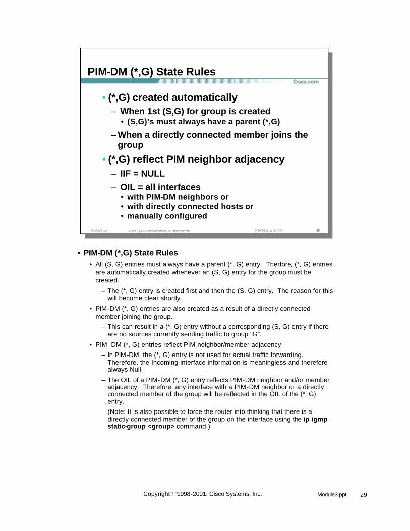
• PIM-DM (*,G) State Rules• All (S, G) entries must always have a parent (*, G) entry. Therfore, (*, G) entries
are automatically created whenever an (S, G) entry for the group must be created.
– The (*, G) entry is created first and then the (S, G) entry. The reason for this will become clear shortly.
• PIM-DM (*, G) entries are also created as a result of a directly connected member joining the group.
– This can result in a (*, G) entry without a corresponding (S, G) entry if there are no sources currently sending traffic to group “G”.
• PIM -DM (*, G) entries reflect PIM neighbor/member adjacency
– In PIM-DM, the (*, G) entry is not used for actual traffic forwarding. Therefore, the Incoming interface information is meaningless and therefore always Null.
– The OIL of a PIM-DM (*, G) entry reflects PIM-DM neighbor and/or member adjacency. Therefore, any interface with a PIM-DM neighbor or a directly connected member of the group will be reflected in the OIL of the (*, G) entry.
(Note: It is also possible to force the router into thinking that there is a directly connected member of the group on the interface using the ip igmp static-group <group> command.)
30Module3.pptCopyright ? ?1998-2001, Cisco Systems, Inc.
Module3. ppt ©1998 – 2001, Cisco Systems, Inc. All rights reserved. 3030308/10/2001 11:41 AM
PIM-DM (S,G) State Rules
• (S,G) created by multicast data arrival– Parent (*,G) created (if doesn’t exist)– IIF = RPF Interface in direction of source– OIL = Copy of OIL from (*,G) minus IIF
• Interfaces in OIL initially “Forward”– Go to “Pruned” state when Prune rcvd– “Forward” intfc timers never expire– “Pruned” intfc timers expire in 3 minutes
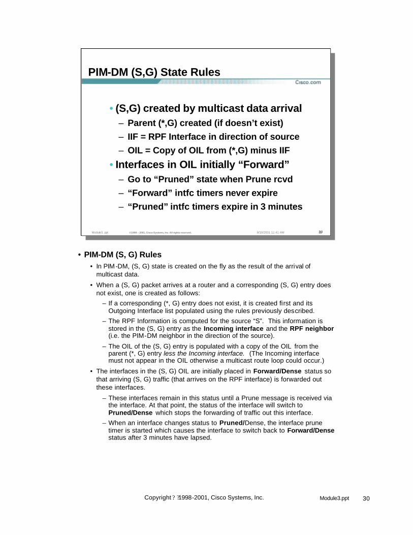
• PIM-DM (S, G) Rules• In PIM-DM, (S, G) state is created on the fly as the result of the arrival of
multicast data.
• When a (S, G) packet arrives at a router and a corresponding (S, G) entry does not exist, one is created as follows:
– If a corresponding (*, G) entry does not exist, it is created first and its Outgoing Interface list populated using the rules previously described.
– The RPF Information is computed for the source “S”. This information is stored in the (S, G) entry as the Incoming interface and the RPF neighbor(i.e. the PIM-DM neighbor in the direction of the source).
– The OIL of the (S, G) entry is populated with a copy of the OIL from the parent (*, G) entry less the Incoming interface. (The Incoming interface must not appear in the OIL otherwise a multicast route loop could occur.)
• The interfaces in the (S, G) OIL are initially placed in Forward/Dense status so that arriving (S, G) traffic (that arrives on the RPF interface) is forwarded out these interfaces.
– These interfaces remain in this status until a Prune message is received via the interface. At that point, the status of the interface will switch to Pruned/Dense which stops the forwarding of traffic out this interface.
– When an interface changes status to Pruned/Dense, the interface prune timer is started which causes the interface to switch back to Forward/Densestatus after 3 minutes have lapsed.

31Module3.pptCopyright ? ?1998-2001, Cisco Systems, Inc.
Module3. ppt ©1998 – 2001, Cisco Systems, Inc. All rights reserved. 3131318/10/2001 11:41 AM
PIM-DM State Flags
• D = Dense Mode• C = Directly Connected Host• L = Local (Router is member)• P = Pruned (All intfcs in OIL = Prune)• T = Forwarding via SPT
– Indicates at least one packet was forwarded• J = Join SPT
– Always on in (*,G) entry in PIM-DM– Basically meaningless in PIM-DM
• PIM-DM State Flags• “D” Flag ((*, G) entries only)
– Indicates the group is operating in Dense mode. (Appears only on (*, G) entries.)
• “C” Flag
– Indicates that there is a member of the group directly connected to the router.
• “L” Flag
– Indicates the router itself is a member of this group and is receiving the traffic. (This would be the case for the Auto-RP Discovery group 224.0.1.40 which all Cisco routers join automatically.)
• “P” Flag
– Set whenever all interfaces in the outgoing interface list of an entry are Pruned (or the list is Null). This general means that the router will send Prune messages to the RPF neighbor to try to shutoff this traffic.)
• “T” Flag ((S, G) entries only)
– Indicates that at least one packet was received via the SPT
• “J” Flag
– Always on in (*,G) entries in PIM -DM. Used by the internal code. Basically meaningless in PIM-DM.

32Module3.pptCopyright ? ?1998-2001, Cisco Systems, Inc.
Module3. ppt ©1998 – 2001, Cisco Systems, Inc. All rights reserved. 3232328/10/2001 11:41 AM
PIM DM Concepts
• PIM Neighbor Discovery• PIM DM State• PIM DM Flooding• PIM DM Pruning• PIM DM Grafting• PIM Assert Mechanism• PIM DM State Maintenance
33Module3.pptCopyright ? ?1998-2001, Cisco Systems, Inc.
Module3. ppt ©1998 – 2001, Cisco Systems, Inc. All rights reserved. 3333338/10/2001 11:41 AM
PIM DM Flooding
S3
S0
rtr-a
rtr-b
S1
E1
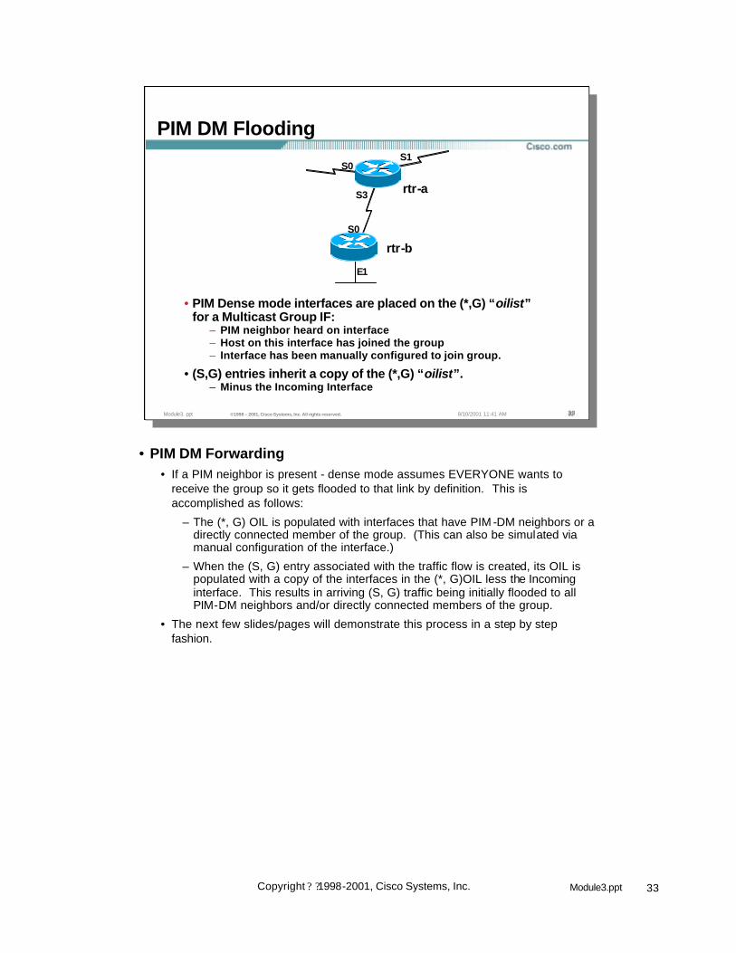
• PIM Dense mode interfaces are placed on the (*,G) “oilist” for a Multicast Group IF:
– PIM neighbor heard on interface– Host on this interface has joined the group– Interface has been manually configured to join group.
• (S,G) entries inherit a copy of the (*,G) “oilist”.– Minus the Incoming Interface
S0
• PIM DM Forwarding• If a PIM neighbor is present - dense mode assumes EVERYONE wants to
receive the group so it gets flooded to that link by definition. This is accomplished as follows:
– The (*, G) OIL is populated with interfaces that have PIM -DM neighbors or a directly connected member of the group. (This can also be simulated via manual configuration of the interface.)
– When the (S, G) entry associated with the traffic flow is created, its OIL is populated with a copy of the interfaces in the (*, G)OIL less the Incoming interface. This results in arriving (S, G) traffic being initially flooded to all PIM-DM neighbors and/or directly connected members of the group.
• The next few slides/pages will demonstrate this process in a step by step fashion.

34Module3.pptCopyright ? ?1998-2001, Cisco Systems, Inc.
Module3. ppt ©1998 – 2001, Cisco Systems, Inc. All rights reserved. 3434348/10/2001 11:41 AM
(*, 224.2.127.254), 00:00:10/00:02:59, RP 0.0.0.0, flags: DIncoming interface: Null, RPF nbr 0.0.0.0Outgoing interface list:Serial0, Forward/Dense, 00:00:10/00:00:00Serial1, Forward/Dense, 00:00:10/00:00:00Serial3, Forward/Dense, 00:00:10/00:00:00
(128.9.160.43/32, 224.2.127.254), 00:00:10/00:02:49, flags: TIncoming interface: Serial0, RPF nbr 198.92.1.129Outgoing interface list:Serial1, Forward/Dense, 00:00:10/00:00:00Serial3, Forward/Dense, 00:00:10/00:00:00
S0
rtr-a
rtr-b
Multicast Packets(128.9.160.43, 224.2.127.254)
S1
E1
S3
PIM DM Flooding
S0Arriving data causes‘rtr-a’ to create state
• Arriving data causes “rtr-a” to create state
• A parent (*, G) entry must first be created before the (S, G) entry can be created.
• The (*, 224.2.127.254) entry is created and the outgoing interface list is populated with interfaces that:
– Have a PIM-DM neighbor or
– Have a directly connected member or
– Has manually be configured to join the group
• (Note: In this example, PIM-DM neighbors are assumed to be connected to ‘rtr-a’ via S0 and S1.)
• The (S, G) entry is then created.• The RPF information for source 128.9.160.43 is computed which results in the
Incoming interface being Serial0 and an RPF neighbor of 198.92.1.129.
• The (S, G) Outgoing interface list (oil) is populated with a copy of the (*,G) oil minus the Incoming interface Serial0.
• This results in Serial1 and Serial3 being in the (S, G) oil.
– The status of these interfaces are initially Forward/Dense which results in the data being flooded out these interfaces.
– Note that the “Expiration” timers on the interfaces in the “oilist” are both 00:00:00. This means that traffic will continue to be forwarded out this interface until a prune is received.
• The “Expiration” countdown timer of the (S, G) entry indicates 00:02:49. This timer will be reset to 00:03:00 whenever an (S, G) packet is forwarded. If the counter reaches zero, the (S, G) entry will be deleted. If it is the last (S,G) entry, the (*, G) entry will also be deleted.

35Module3.pptCopyright ? ?1998-2001, Cisco Systems, Inc.
Module3. ppt ©1998 – 2001, Cisco Systems, Inc. All rights reserved. 3535358/10/2001 11:41 AM
(*, 224.2.127.254), 00:00:10/00:02:59, RP 0.0.0.0, flags: DIncoming interface: Null, RPF nbr 0.0.0.0Outgoing interface list:Serial0, Forward/Dense, 00:00:10/00:00:00Serial1, Forward/Dense, 00:00:10/00:00:00Serial3, Forward/Dense, 00:00:10/00:00:00
(128.9.160.43/32, 224.2.127.254), 00:00:10/00:02:49, flags: TIncoming interface: Serial0, RPF nbr 198.92.1.129Outgoing interface list:Serial1, Forward/Dense, 00:00:10/00:00:00Serial3, Forward/Dense, 00:00:10/00:00:00
PIM DM Flooding
S3
S0
rtr-a
rtr-b
S1
E1
Packets are “flooded” out all interfaces in (S, G) “oilist”.
Multicast Packets(128.9.160.43, 224.2.127.254)
S0
Outgoing interface list:Serial1, Forward/Dense, 00:00:10/00:00:00Serial3, Forward/Dense, 00:00:10/00:00:00
• Initial Flooding• Now that the (*, G) and (S, G) entries have been created, the router begins to
forward all (S, G) multicast traffic based on the (S, G) entry.
• Traffic arriving at ‘rtr-b’ will be RPF checked against the Incoming interface, Serial0. Any (S, G) packets that do not arrive via this interface will fail the RPF check and be discarded. Traffic arriving via this interface will RPF check successfully and be forwarded based on the (S, G) OIL.
• At this point in the example, that status of both Serial1 and Serial3 in the OIL are both Forward/Dense. This causes arriving (S, G) traffic (that RPF checks) to initially be flooded out these two interfaces.

36Module3.pptCopyright ? ?1998-2001, Cisco Systems, Inc.
Module3. ppt ©1998 – 2001, Cisco Systems, Inc. All rights reserved. 3636368/10/2001 11:41 AM
(*, 224.2.127.254), 00:00:12/00:02:59, RP 0.0.0.0, flags: DIncoming interface: Null, RPF nbr 0.0.0.0Outgoing interface list:Serial0, Forward/Dense, 00:00:12/00:00:00
(128.9.160.43/32, 224.2.127.254), 00:00:12/00:02:48, flags: PTIncoming interface: Serial0, RPF nbr 198.92.2.31Outgoing interface list: Null
PIM DM Flooding
Multicast Packets(128.9.160.43, 224.2.127.254)
S0
rtr-a
rtr-b
S1
E1
S3
Arriving data causes‘rtr-b’ to create state
S0
• Arriving data causes “rtr-b” to create state
• A parent (*, G) entry must first be created before the (S, G) entry can be created.
• The (*, 224.2.127.254) entry is created and the outgoing interface list is populated with interfaces that:
– Have a PIM-DM neighbor or– Have a directly connected member or– Has manually be configured to join the group
• This results in only Serial0 being places in the (*,G) oil.
• The (S, G) entry is then created.• The RPF information for source 128.9.160.43 is computed which results in the
Incoming interface being Serial0 and an RPF neighbor of 198.92.2.31.
• The (S, G) Outgoing interface list (oil) is populated with a copy of the (*,G) oil minus the Incoming interface Serial0.
• The removal of the Incoming interface results in the (S, G) oil being Null.
– The “P” flag is set on the (S, G) entry which indicates that ‘rtr-b’ will send a Prune messages to ‘rtr-a’. (See the section on Pruning.)
• The “Expires” countdown timer of the (S, G) entry indicates 00:02:48. This timer would normally be reset to 00:03:00 whenever an (S, G) packet is forwarded. However, since the (S, G) entry has a Null oil, the counter will reach zero in 2 minutes and 48 seconds, at which time the (S, G) entry will be deleted. If it is the last (S,G) entry, the (*, G) entry will be deleted. (The arrival of another (S, G) packet from ‘rtr-a’ will recreate the state as described above.)

37Module3.pptCopyright ? ?1998-2001, Cisco Systems, Inc.
Module3. ppt ©1998 – 2001, Cisco Systems, Inc. All rights reserved. 3737378/10/2001 11:41 AM
Source
Interface previously Prunedby Assert Process
Normal Steady-State Traffic Flow
RPF Interface
Potential PIM-DM Route Loop
• Potential PIM-DM Route Loops• The non-deterministic behavior of PIM -DM along with its flood-and-prune
mechanism can sometimes result in serious network outages including “blackholes ” and multicast route loops.
• The network in the above example is a simplified version of a frequently used network design whereby multiple routers are used to provide redundancy in the network.
• Under normal steady -state conditions, traffic flows from the source via the RPF interfaces as shown.
– Note that the routers have performed the Assert process and one interface on one router is in the pruned state.

38Module3.pptCopyright ? ?1998-2001, Cisco Systems, Inc.
Module3. ppt ©1998 – 2001, Cisco Systems, Inc. All rights reserved. 3838388/10/2001 11:41 AM
Interface Fails
Source
This Router converges first
RPF Interface
XX
Potential PIM-DM Route Loop
• Potential PIM-DM Route Loops• Now let’s assume that the forwarding interface of the first-hop router fails as
shown above.
• Let’s also assume that the unicast routing of router on the left converges first and PIM computes the new RPF interface as shown.

39Module3.pptCopyright ? ?1998-2001, Cisco Systems, Inc.
Module3. ppt ©1998 – 2001, Cisco Systems, Inc. All rights reserved. 3939398/10/2001 11:41 AM
Source
RPF Interface
XXBut wait . . .This Router stillhasn’t converged yet
New Traffic Flow
Multicast Route Loop ! !Multicast Route Loop ! !
Potential PIM-DM Route Loop
• Potential PIM-DM Route Loops• Unfortunately, the middle router has not yet converged and is still forwarding
multicast traffic using the old RPF interface.
• At this point, a multicast route loop exists in the network due to the transient condition of the two routers having opposite RPF interfaces.
• During the time that this route loop exists, virtually all of the bandwidth on the network segments can be consumed. This situation will continue until the router in the middle of the picture finally converges and the new “correct” RPF interface is calculated.
• Unfortunately, if the router needs some bandwidth to complete this convergence (as in the case when EIGRP goes active), then this condition will never be resolved!

40Module3.pptCopyright ? ?1998-2001, Cisco Systems, Inc.
Module3. ppt ©1998 – 2001, Cisco Systems, Inc. All rights reserved. 4040408/10/2001 11:41 AM
PIM DM Concepts
• PIM Neighbor Discovery• PIM DM State• PIM DM Flooding• PIM DM Pruning• PIM DM Grafting• PIM Assert Mechanism• PIM DM State Maintenance

41Module3.pptCopyright ? ?1998-2001, Cisco Systems, Inc.
Module3. ppt ©1998 – 2001, Cisco Systems, Inc. All rights reserved. 4141418/10/2001 11:41 AM
(*, 224.2.127.254), 00:00:10/00:02:59, RP 0.0.0.0, flags: DIncoming interface: Null, RPF nbr 0.0.0.0Outgoing interface list:Serial0, Forward/Dense, 00:00:10/00:00:00Serial1, Forward/Dense, 00:00:10/00:00:00Serial3, Forward/Dense, 00:00:10/00:00:00
(128.9.160.43/32, 224.2.127.254), 00:00:10/00:02:49, flags: TIncoming interface: Serial0, RPF nbr 198.92.1.129Outgoing interface list:Serial1, Forward/Dense, 00:00:10/00:00:00Serial3, Forward/Dense, 00:00:10/00:00:00
Initial “Flooding” Statein “rtr-a”
S0
rtr-a
rtr-b
Multicast Packets(128.9.160.43, 224.2.127.254)
S1
E1
S3
PIM DM Pruning
S0
• Initial “Flooding” State in “rtr-a”• Let us again review the state in the router that resulted in the initial flooding of
(S, G) traffic. Pay particular attention to the following:
– Both an (*, G) and (S, G) entry exist. In PIM DM, (*, G) entries are created automatically as soon as the first packet (from any source) arrives for group “G” or when a locally connected host has joined the group via IGMP.
– Both Serial1 and Serial3 are in the “Outgoing interface list” (oilist) for the (S, G) entry. This is because there is a PIM Neighbor on these interfaces in this example.
– The “Expires” times on the interfaces in the “oilist” are both 00:00:00. This is because in PIM DM, only “pruned” interfaces timeout since we are using a flood and prune model.

42Module3.pptCopyright ? ?1998-2001, Cisco Systems, Inc.
Module3. ppt ©1998 – 2001, Cisco Systems, Inc. All rights reserved. 4242428/10/2001 11:41 AM
11 “rtr-a” initially floods (S, G) traffic out all interfaces in “oilist”.
Multicast Packets(128.9.160.43, 224.2.127.254)
22 “rtr-b” is a leaf node w/o receivers. Sends Prune for (S,G).
Prune22
33 “rtr-a” Prunes interface for (S,G).
S0
rtr-a
rtr-b
S1
E1
33XX
S3
PIM DM Pruning
S0
• Step 1• As a result of the initial flooding state (shown in the previous slide), ‘rtr-a’ is
flooding (S, G) traffic out interfaces Serial3 and Serial 1.
• Step 2• ‘rtr-b’ is a leaf node without any downstream PIM-DM neighbors or directly
connected members of the group. This is reflected in rtr-b’s (S, G) entry (shown in the previous slide) by the Null OIL and the corresponding “P” flag being set.
• As a result of the above, ‘rtr-b’ sends an (S, G) Prune message to ‘rtr-a’ to shutoff the flow of unwanted traffic.
• Step 3• ‘rtr-a’ responds by pruning interface Serial3. (This is reflected in the (S, G) state
shown in the next slide.)

43Module3.pptCopyright ? ?1998-2001, Cisco Systems, Inc.
Module3. ppt ©1998 – 2001, Cisco Systems, Inc. All rights reserved. 4343438/10/2001 11:41 AM
(*, 224.2.127.254), 00:00:12/00:02:59, RP 0.0.0.0, flags: DIncoming interface: Null, RPF nbr 0.0.0.0Outgoing interface list:Serial0, Forward/Dense, 00:00:12/00:00:00Serial1, Forward/Dense, 00:00:12/00:00:00Serial3, Forward/Dense, 00:00:12/00:00:00
(128.9.160.43/32, 224.2.127.254), 00:00:12/00:02:48, flags: TIncoming interface: Serial0, RPF nbr 198.92.1.129Outgoing interface list:Serial1, Forward/Dense, 00:00:12/00:00:00Serial3, Prune/Dense, 00:00:12/00:02:56
Multicast Packets(128.9.160.43, 224.2.127.254)
S0
rtr-a
rtr-b
S1
E1
S3
State in “rtr-a”after Pruning
PIM DM Pruning
S0
• State in “rtr-a” after Pruning• Pay particular attention to the following:
– Serial3 in the “Outgoing interface list” (oilist) for the (S, G) entry is now in the “Pruned” state.
– The “Expires” time on interface Serial3 now shows 00:02:56 which indicates that the “Prune” state will expire in 2 minutes and 56 seconds. At that time, the interface will return to the “Forward” state and (S, G) traffic will once again be flooded to “rtr-b”. When this happens, “rtr-b” will have to send another Prune to “rtr-a” to shutoff the unwanted (S, G) traffic. This periodic “flood and prune” behavior is normal for PIM Dense mode.

44Module3.pptCopyright ? ?1998-2001, Cisco Systems, Inc.
Module3. ppt ©1998 – 2001, Cisco Systems, Inc. All rights reserved. 4444448/10/2001 11:41 AM
(*, 224.2.127.254), 00:00:12/00:02:59, RP 0.0.0.0, flags: DIncoming interface: Null, RPF nbr 0.0.0.0Outgoing interface list:Serial0, Forward/Dense, 00:00:12/00:00:00
(128.9.160.43/32, 224.2.127.254), 00:00:12/00:02:48, flags: PTIncoming interface: Serial0, RPF nbr 198.92.2.31Outgoing interface list: Null
PIM DM Pruning
Multicast Packets(128.9.160.43, 224.2.127.254)
S0
rtr-a
rtr-b
S1
E1
S3
State in ‘rtr-b’ before/after Pruning
S0
• State in “rtr-b” after Pruning• Pay particular attention to the following:
– The “Outgoing interface list” (oilist) for the (S, G) entry is still Null and the “P” flag is still set. This indicates that ‘rtr-b’ will send (S, G) Prunes out the Incoming interface to ‘rtr-a’ which is the RPF neighbor in the direction of the source.

45Module3.pptCopyright ? ?1998-2001, Cisco Systems, Inc.
Module3. ppt ©1998 – 2001, Cisco Systems, Inc. All rights reserved. 4545458/10/2001 11:41 AM
(S,G) Packets
E0
11 “rtr-b” is a leaf node w/o receivers. Sends Prune for (S,G).
Prune11
22 “rtr-a” schedules a Prune for (S,G) to occur in 3 seconds.
I’ll wait 3 secs to see if someone else wants (S,G) before I Prune
Interface E0.
22
33 “rtr-c” hears Prune from “rtr-b”. Overrides with a Join.
Join 33
44 “rtr-a” hears Join and cancels Prune for (S,G).
S0
Receiver
rtr-b rtr-c
S1rtr-a
E0
E1
E0
E1
44
PIM Prune Delay on Multiaccess Networks
• PIM Prune Delay on Multi-access Networks• rtr-a schedules a prune when asked but doesn’t do it right away because it
received the (S, G) Prune on a multi-access interface. This gives any other router on the LAN the chance to override the (S, G) Prune if they still need the (S, G) traffic.
• In the above example, this process occurs as follows:
– ‘rtr-b’ is a leaf node with no downstream neighbors or directly connected members so it sends an (S, G) prune.
– ‘rtr-a’ receives this (S, G) Prune and “schedules” the prune of interface Ethernet0 to occur in 3 seconds.
– ‘rtr-c’ overhears to (S, G) Prune sent to ‘rtr-a’. (It overheard this because all PIM control messages are multicast on the local wire.) Because ‘rtr-c’ has a directly connected member, it overrides the (S,G) Prune by sending an (S, G) Join to ‘rtr-a’.
– When ‘rtr-a’ hears this (S, G) Join, it cancels the Prune scheduled for interface Ethernet0.
• If there was local igmp state for this group on ‘rtr-a’ (i.e. there was a directly connected member on the LAN) and neither rtr-b and rtr-c had downstream members (and therefore did not override the (S, G) Prune), the (S, G) Prune would be ignored by rtr-a.

46Module3.pptCopyright ? ?1998-2001, Cisco Systems, Inc.
Module3. ppt ©1998 – 2001, Cisco Systems, Inc. All rights reserved. 4646468/10/2001 11:41 AM
Watch out for the ripple affect of this Delay!!!Watch out for the ripple affect of this Delay!!!
• Source begins sending traffic which is flooded everywhere.
• Leaf router has no receivers; sends prune which ripples up the tree.
Prune
3 sec delay
XX
Prune
3 sec delay
XX
Prune
3 sec delay
XX
Prune
Source
3 sec delay
XX
• Total time to prune back to source = 12 seconds!
• Process repeats 3 minutes later when prunes timeout!
PIM Prune Delay on Multiaccess Networks
• Accumulative Affect of Prune Delays• The 3 second prune delay on multi-access networks can be accumulative and
should be taken into account during PIM -DM network design.
• In the above example, a source is transmitting to a multicast group for which there are no members. The normal prune process is initiated by the router on the far right. However, due to the normal 3 second Prune Delay on multi-access links, the upstream router does not prune its interface for three seconds. When this does happen, the upstream router itself then triggers a Prune to its upstream router. Because this router is also connected via a multi-access network, this prune will also be delayed by three seconds. This process continues ad-nauseum until it reaches the first hop router directly connected to the source. In this example, a total of 12 seconds was required to completely shutoff the flow of unwanted traffic.
• Unfortunately, this process is repeated three minutes later when the prunes timeout and re-flooding occurs..

47Module3.pptCopyright ? ?1998-2001, Cisco Systems, Inc.
Module3. ppt ©1998 – 2001, Cisco Systems, Inc. All rights reserved. 4747478/10/2001 11:41 AM
PIM DM Concepts
• PIM Neighbor Discovery• PIM DM State• PIM DM Flooding• PIM DM Pruning• PIM DM Grafting• PIM Assert Mechanism• PIM DM State Maintenance

48Module3.pptCopyright ? ?1998-2001, Cisco Systems, Inc.
Module3. ppt ©1998 – 2001, Cisco Systems, Inc. All rights reserved. 4848488/10/2001 11:41 AM
PIM DM Grafting
• “rtr-b” and “rtr-c” have previously Pruned (S,G) traffic.
• “rtr-a” is still forwarding traffic downstream via S1.
Beginning State
E0
S0
rtr-a
rtr-b
(S,G) Packets
rtr-c
E0
E1
E0
E1
S1
• PIM DM Grafting Example• Initially, “rtr-b” and “rtr-c” have previously Pruned (S, G) traffic.
• “rtr-a” is still forwarding traffic downstream via S1 which, for this example, we’ll assume hasn’t been pruned.

49Module3.pptCopyright ? ?1998-2001, Cisco Systems, Inc.
Module3. ppt ©1998 – 2001, Cisco Systems, Inc. All rights reserved. 4949498/10/2001 11:41 AM
(*, 224.2.127.254), 00:04:10/00:02:59, RP 0.0.0.0, flags: DIncoming interface: Null, RPF nbr 0.0.0.0Outgoing interface list:Serial0, Forward/Dense, 00:04:10/00:00:00Serial1, Forward/Dense, 00:04:10/00:00:00Ethernet0, Forward/Dense, 00:04:10/00:00:00
(128.9.160.43/32, 224.2.127.254), 00:04:10/00:02:39, flags: TIncoming interface: Serial0, RPF nbr 198.92.1.129Outgoing interface list:Ethernet0, Prune/Dense, 00:01:29/00:01:30Serial1, Forward/Dense, 00:04:10/00:00:00
PIM DM Grafting
Beginning Statein “rtr-a”
E0
S0
rtr-b rtr-c
E0
E1
E0
E1
rtr-aS1
(S,G) Packets
• Beginning State in “rtr-a”• Pay particular attention to the following:
– Ethernet0 in the “Outgoing interface list” (oilist) for the (S, G) entry is in the “Pruned” state.

50Module3.pptCopyright ? ?1998-2001, Cisco Systems, Inc.
Module3. ppt ©1998 – 2001, Cisco Systems, Inc. All rights reserved. 5050508/10/2001 11:41 AM
(*, 224.2.127.254), 00:04:10/00:02:59, RP 0.0.0.0, flags: DIncoming interface: Null, RPF nbr 0.0.0.0Outgoing interface list:Ethernet0, Forward/Dense, 00:04:10/00:00:00
(128.9.160.43/32, 224.2.127.254), 00:04:10/00:02:39, flags: PTIncoming interface: Ethernet0, RPF nbr 198.92.2.1Outgoing interface list: Null
Beginning State in “rtr-b”
PIM DM Grafting
E0
S0
rtr-b rtr-c
E0
E1
E0
E1
rtr-aS1
(S,G) Packets
• Beginning State in “rtr-b”• Pay particular attention to the following:
– The “Incoming interface” for the (S, G) entry is Ethernet0.
– The “Outgoing interface list” for the (S, G) entry is Null.
– The “P” flag is set in the (S, G) entry which indicates the entry is in the “Pruned” state.

51Module3.pptCopyright ? ?1998-2001, Cisco Systems, Inc.
Module3. ppt ©1998 – 2001, Cisco Systems, Inc. All rights reserved. 5151518/10/2001 11:41 AM
PIM DM Grafting
(*, 224.2.127.254), 00:04:10/00:02:59, RP 0.0.0.0, flags: DIncoming interface: Null, RPF nbr 0.0.0.0Outgoing interface list:Ethernet0, Forward/Dense, 00:04:10/00:00:00
(128.9.160.43/32, 224.2.127.254), 00:04:10/00:02:39, flags: PTIncoming interface: Ethernet0, RPF nbr 198.92.2.1Outgoing interface list: Null
Beginning State in “rtr-c”
E0
S0
rtr-b rtr-c
E0
E1
E0
E1
rtr-aS1
(S,G) Packets
• Beginning State in “rtr-c”• Pay particular attention to the following:
– The “Incoming interface” for the (S, G) entry is Ethernet0.
– The “Outgoing interface list” for the (S, G) entry is Null.
– The “P” flag is set in the (S, G) entry which indicates the entry is in the “Pruned” state.

52Module3.pptCopyright ? ?1998-2001, Cisco Systems, Inc.
Module3. ppt ©1998 – 2001, Cisco Systems, Inc. All rights reserved. 5252528/10/2001 11:41 AM
PIM DM Grafting
E0
S0
rtr-b
Rcvr A
• “Rcvr A” wishes to receive group G traffic. Sends IGMP Join for G.11
IGMP Join 11
• “rtr-b” sends PIM Graft for Group (S,G).22
PIM Graft22
• “rtr-a” acknowledges with a PIM Graft-Ack.33
PIM Graft-ACK33
• “rtr-a” begins forwarding traffic for (S,G).44
rtr-c
44
E0
E1
E0
E1
rtr-aS1
(S,G) Packets
• PIM DM Grafting Example (cont.)• 1) “Rcvr A” wishes to receive group “G” traffic. Therefore, it sends an IGMP
Host Membership Report to “rtr-b”. “rtr-b” receives the IGMP Host Membership Report and creates IGMP Group state on the interface toward “Rcvr A”.
• 2) “rtr-b” already has (*, G) and (S, G) state. However, the interface towards “Rcvr A” is in the “Prune” state. Therefore “rtr-b” sends a PIM Graft to its up-stream neighbor “rtr-a”, in the direction of the source.
• 3) “rtr-a” receives the Graft and acknowledges with a Graft -Ack.
• 4) “rtr-a” begins forwarding traffic for (S, G).

53Module3.pptCopyright ? ?1998-2001, Cisco Systems, Inc.
Module3. ppt ©1998 – 2001, Cisco Systems, Inc. All rights reserved. 5353538/10/2001 11:41 AM
(*, 224.2.127.254), 00:04:10/00:02:59, RP 0.0.0.0, flags: DIncoming interface: Null, RPF nbr 0.0.0.0Outgoing interface list:Serial0, Forward/Dense, 00:04:10/00:00:00Serial1, Forward/Dense, 00:04:10/00:00:00Ethernet0, Forward/Dense, 00:04:10/00:00:00
(128.9.160.43/32, 224.2.127.254), 00:04:10/00:02:39, flags: TIncoming interface: Serial0, RPF nbr 198.92.1.129Outgoing interface list:Ethernet0, Forward/Dense, 00:00:25/00:00:00Serial1, Forward/Dense, 00:04:10/00:00:00
PIM DM Grafting
E0
S0
rtr-b rtr-c
E0
E1
E0
E1
rtr-aS1
State in “rtr-a”after Grafting
(S,G) Packets
• State in “rtr-a” after Grafting• Pay particular attention to the following:
– Both Ethernet0 and Serial1 in the “Outgoing interface list” (oilist) for the (S, G) entry are now in the “Forward” state.

54Module3.pptCopyright ? ?1998-2001, Cisco Systems, Inc.
Module3. ppt ©1998 – 2001, Cisco Systems, Inc. All rights reserved. 5454548/10/2001 11:41 AM
(*, 224.2.127.254), 00:04:10/00:00:00, RP 0.0.0.0, flags: DIncoming interface: Null, RPF nbr 0.0.0.0Outgoing interface list:Ethernet0, Forward/Dense, 00:04:10/00:00:00Ethernet1, Forward/Dense, 00:04:10/00:00:00
(128.9.160.43/32, 224.2.127.254), 00:04:10/00:02:39, flags: CTIncoming interface: Ethernet0, RPF nbr 198.92.2.1Outgoing interface list: Ethernet1, Forward/Dense, 00:00:26/00:00:00
(*, 224.2.127.254), 00:04:10/00:00:00, RP 0.0.0.0, flags: DIncoming interface: Null, RPF nbr 0.0.0.0Outgoing interface list:Ethernet0, Forward/Dense, 00:04:10/00:00:00Ethernet1, Forward/Dense, 00:04:10/00:00:00
(128.9.160.43/32, 224.2.127.254), 00:04:10/00:02:39, flags: CCTIncoming interface: Ethernet0, RPF nbr 198.92.2.1Outgoing interface list: Ethernet1, Forward/Dense, 00:00:26/00:00:00
State in “rtr-b” after Grafting
PIM DM Grafting
E0
S0
rtr-b rtr-c
E0
E1
E0
E1
rtr-aS1
(S,G) Packets
• State in “rtr-b” after Grafting• Pay particular attention to the following:
– Ethernet1 is now in the (S, G) “Outgoing interface list” and is in the “Forward” state.
– The “P” flag has been cleared in the (S, G) entry
– The “T” flag is set indicating that traffic is successfully flowing down the Shortest-Path Tree.

55Module3.pptCopyright ? ?1998-2001, Cisco Systems, Inc.
Module3. ppt ©1998 – 2001, Cisco Systems, Inc. All rights reserved. 5555558/10/2001 11:41 AM
PIM DM Grafting
(*, 224.2.127.254), 00:04:10/00:02:59, RP 0.0.0.0, flags: DIncoming interface: Null, RPF nbr 0.0.0.0Outgoing interface list:Ethernet0, Forward/Dense, 00:04:10/00:00:00
(128.9.160.43/32, 224.2.127.254), 00:04:10/00:02:39, flags: PTIncoming interface: Ethernet0, RPF nbr 198.92.2.1Outgoing interface list: Null
State in “rtr-c” after Grafting
E0
S0
rtr-b rtr-c
E0
E1
E0
E1
rtr-aS1
(S,G) Packets
• State in “rtr-c” after Grafting• Notice there has been no change in the state:
– The “Incoming interface” for the (S, G) entry is Ethernet0.
– The “Outgoing interface list” for the (S, G) entry is Null.
– The “P” flag is set in the (S, G) entry which indicates the entry is in the “Pruned” state.
• The obvious question at this point is, “Will ‘rtr-c’ begin sending (S, G) Prunes in an attempt to shutoff this unwanted traffic?” The answer is no because rate-limited prunes are only sent on P2P interfaces. This implies the following:
– When (S, G) traffic is received on the RPF interface which is a non-P2P link (in this case an Ethernet) and the OIL is Null, an (S, G) Prune message is sent only once at the time the (S, G) entry transitions to a Null OIL.
– This implies that when the (S, G) entry expires and is deleted, the next arriving (S, G) packet will recreate the (S, G) entry and another single (S, G) Prune will triggered by ‘rtr-c’ which will be overriden by an (S, G) Join by ‘rtr-b’.
– As long as the source remains active, this periodic Prune and Join override will occur every three minutes.

56Module3.pptCopyright ? ?1998-2001, Cisco Systems, Inc.
Module3. ppt ©1998 – 2001, Cisco Systems, Inc. All rights reserved. 5656568/10/2001 11:41 AM
PIM DM Concepts
• PIM Neighbor Discovery• PIM DM State• PIM DM Flooding• PIM DM Pruning• PIM DM Grafting• PIM Assert Mechanism• PIM DM State Maintenance

57Module3.pptCopyright ? ?1998-2001, Cisco Systems, Inc.
Module3. ppt ©1998 – 2001, Cisco Systems, Inc. All rights reserved. 5757578/10/2001 11:41 AM
PIM Assert Mechanism
E0.1
E0.2
S0
Routers A & B receive packet on an interface in their “oilist”!!– Only one router should continue sending to avoid duplicate
packets.
11
S0
11
192.168.1.0/24
Receiver
Incoming Multicast Packet(Successful RPF Check)
AA BB
CC
• PIM Assert Mechanism• The PIM Assert mechanism is used to shutoff duplicate flows onto the same
multi-access network.
– Routers detect this condition when they receive an (S, G) packet via a multi-access interface that it is in the (S, G) OIL.
– This is explained in the example presented in the next few slides.
• Step 1• Routers A & B receive both receive the same (S, G) traffic via their proper RPF
interfaces (Serial0) and forward the packet onto the common Ethernet segment. Routers A & B therefore will receive an (S, G) packet via a multi-access interface that is in the Outgoing Interface list of their (S, G) entry. This triggers the Assert mechanism.

58Module3.pptCopyright ? ?1998-2001, Cisco Systems, Inc.
Module3. ppt ©1998 – 2001, Cisco Systems, Inc. All rights reserved. 5858588/10/2001 11:41 AM
Receiver
PIM Assert Mechanism
E0.1
E0.2
S0S0
22 Routers send “PIM Assert” messages
Assert<distance, metric>
Assert<distance, metric>
2222
– Compare distance and metric values– Router with best route to source wins– If metric & distance equal, highest IP adr wins
192.168.1.0/24
Loser Winner
X Pruned
– Losing router stops sending (prunes interface)
AA BB
CC
• Step 2• Routers A & B both send PIM Assert messages that contain their Administrative
Distance and route Metric back to the source.
– Note: The Administrative Distance and route Metric is treated as a single combined numeric value where the Administrative Distance is the high-order part of the numeric value. Therefore, even though different routing protocols use different metrics, the lower Administrative Distance will take precedence.
• Each router compares the received Administrative Distance/Metric value with its own and the router with the best (lowest) value wins the Assert.
– In case of a tie, the highest IP address is used as the tie breaker.
• The losing router will Prune its interface just as if it had received a Prune on this interface.
– Note: This prune will timeout in 3 minutes and cause the router to begin forwarding on this interface again. This triggers another Assert process. By the same token, if the winning router were to crash, the loser would take over the job of forwarding onto this LAN segment after its prune timed out.

59Module3.pptCopyright ? ?1998-2001, Cisco Systems, Inc.
Module3. ppt ©1998 – 2001, Cisco Systems, Inc. All rights reserved. 5959598/10/2001 11:41 AM
PIM Assert Mechanism
E0.1
Incoming Multicast Packet(Successful RPF Check)
E0.2
S0S0
192.168.1.0/24
X
If there are no directly connected members on the interface, the winning router sends a Prune and waits 3 seconds for a Join override.– This will shutoff traffic if it is not needed somewhere downstream.
33
Prune33
Receiver
Router C does need traffic. Sends join to override.44
Join 44
CC
Loser Winner
BBAA
• Step 3• In the case where there are no directly connected members on the LAN
segment (as is the case in our example), the winning router will send an (S,G) Prune message and schedule its interface to be pruned after the normal 3 second prune delay.
– This mechanism allows traffic to be shutoff if there are no members of the group further downstream of the LAN segment. (Which is not the case in the figure above.
• Step 4• In this example, downstream router C does need the traffic (it has a directly
connected receiver) so it responds to the (S, G) Prune sent by the winning router by sending an overriding (S, G) Join. This cancels the scheduled Prune in Router B and thereby continues the flow of (S, G) traffic onto the transit LAN.

60Module3.pptCopyright ? ?1998-2001, Cisco Systems, Inc.
Module3. ppt ©1998 – 2001, Cisco Systems, Inc. All rights reserved. 6060608/10/2001 11:41 AM
PIM Assert Mechanism
E0.1
Incoming Multicast Packet(Successful RPF Check)
E0.2
S0S0
192.168.1.0/24
X
If router C doesn’t need the traffic, no Join override is sent.55
66AA BB
CC
55X Pruned
Router B prunes its interface after 3 second prune delay.66– This stops the flow of traffic onto the transit LAN.
Loser Winner
• Step 5• On the other hand, if the none of the downstream router(s) need the traffic (as is
the case in the example shown above), no (S, G) Join is sent to override the (S, G) Prune sent by the winning router, Router B.
• Step 6• After the normal 3 second Prune delay expires and Router B has not received
an (S, G) Join to override the prune, it goes ahead and Prunes its interface. This shuts off the flow of traffic onto the transit LAN segment.
– Note: The prune of Router B’s Ethernet interface will timeout after 3 minutes just as if it had received an (S, G) prune on this interface. This means that traffic will start to flow via this interface after 3 minutes which will trigger Router A to start the Assert process all over again.

61Module3.pptCopyright ? ?1998-2001, Cisco Systems, Inc.
Module3. ppt ©1998 – 2001, Cisco Systems, Inc. All rights reserved. 6161618/10/2001 11:41 AM
(128.9.160.43/32, 224.2.127.254), 00:04:10/00:02:39, flags:PTIncoming interface: Ethernet0, RPF nbr 198.92.2.2Outgoing interface list: Null
State in Router C before Assert
RPF Neighbor
S0S0
PIM Assert Mechanism
AA BB
CC
198.92.2.0/24
• Downstream routers must listen for the assert winner to know which router to send prunes and grafts
E0 E0 .2.1
Routing Protocol Boundary
• Downstream routers on the Assert LAN• It is important for downstream routers that are on the Assert LAN to note who
wins the Assert process. This is because it must address any PIM (S,G) control messages (Joins, Prunes, Grafts) to the RPF neighbor (i.e. upstream neighbor) in the direction of the source.
• In this example, assume that Router A has a better metric to the source. However, because there is a routing protocol boundary between Router C and the other two routers, Router C’s unicast routing table does not know that Router A has better metric to the source. As a result, the unicast routing table in Router C indicates that the best route back to the source is via Router B. This is reflected by the RPF nbr field of the (S, G) entry.

62Module3.pptCopyright ? ?1998-2001, Cisco Systems, Inc.
Module3. ppt ©1998 – 2001, Cisco Systems, Inc. All rights reserved. 6262628/10/2001 11:41 AM
(128.9.160.43/32, 224.2.127.254), 00:04:10/00:02:39, flags:PTIncoming interface: Ethernet0, RPF nbr 198.92.2.2Outgoing interface list: Null
Assert Winner
E0 E0
S0S0
198.92.2.0/24
Incoming Multicast Packet(Successful RPF Check)
.2.1
PIM Assert Mechanism
AA BB
CC
AssertAssert
Routing Protocol Boundary
RPF Neighbor
Assert Loser
• Downstream routers on the Assert LAN (cont.)• When traffic begins to flow, it triggers Routers A & B to send Assert messages.
• Because Router A has a better (lower) metric to the source than Router B and therefore Router A wins the assert.
63Module3.pptCopyright ? ?1998-2001, Cisco Systems, Inc.
Module3. ppt ©1998 – 2001, Cisco Systems, Inc. All rights reserved. 6363638/10/2001 11:41 AM
(128.9.160.43/32, 224.2.127.254), 00:04:10/00:02:39, flags:PTIncoming interface: Ethernet0, RPF nbr 198.92.2.2Outgoing interface list: Null
Assert LoserAssert Winner
E0 E0
S0S0
198.92.2.0/24
.2.1
PIM Assert Mechanism
AA BB
CC
Routing Protocol BoundaryX Pruned
Incoming Multicast Packet(Successful RPF Check)
RPF Neighbor
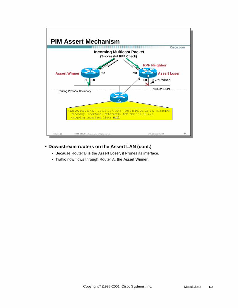
• Downstream routers on the Assert LAN (cont.)• Because Router B is the Assert Loser, it Prunes its interface.
• Traffic now flows through Router A, the Assert Winner.

64Module3.pptCopyright ? ?1998-2001, Cisco Systems, Inc.
Module3. ppt ©1998 – 2001, Cisco Systems, Inc. All rights reserved. 6464648/10/2001 11:41 AM
(128.9.160.43/32, 224.2.127.254), 00:04:10/00:02:39, flags:PTIncoming interface: Ethernet0, RPF nbr 198.92.2.1198.92.2.1Outgoing interface list: Null
State in Router C after Assert Assert Winner
S0S0Assert Winner
PIM Assert Mechanism
RPF Neighbor
AA BB
CC
198.92.2.0/24
E0 E0 .2.1
Routing Protocol Boundary
Assert Loser
Incoming Multicast Packet(Successful RPF Check)
• Downstream routers on the Assert LAN (cont.)• Because Router C has overheard the Assert process (because PIM control
messages are multicast onto the local link), it was able to determine who has won the Assert process.
• Router C now updates its RPF nbr information to reflect that Router A is now the correct upstream neighbor in the direction of the source. This will result in any (S, G) PIM control traffic (Joins, Prunes, Grafts) being sent with the IP address of Router A in the Upstream Neighbor Address field of the PIM control message.
– If Router C didn’t update its RPF nbr information and continued to send PIM control traffic (Joins, Prunes, Grafts) to Router B (the old RPF nbr), it would not be able to properly control the flow of multicast traffic since the control messages would be going to the wrong upstream neighbor.

65Module3.pptCopyright ? ?1998-2001, Cisco Systems, Inc.
Module3. ppt ©1998 – 2001, Cisco Systems, Inc. All rights reserved. 6565658/10/2001 11:41 AM
Receiver
Initial Flow
Source
Multicast Packets
PIM-DM Assert Problem
Receiver
Duplicate Traffic
• PIM-DM Assert Problem• While the PIM Assert mechanism is effective in pruning off duplicate traffic, it is
not without its weaknesses.
• Consider the above example where duplicate traffic is flowing onto a LAN segment.

66Module3.pptCopyright ? ?1998-2001, Cisco Systems, Inc.
Module3. ppt ©1998 – 2001, Cisco Systems, Inc. All rights reserved. 6666668/10/2001 11:41 AM
Receiver
Sending Asserts
Source
Multicast Packets
PIM-DM Assert Problem
Receiver
Assert Messages
Loser
Winner
• PIM-DM Assert Problem• The normal PIM Assert mechanism takes place and the two routers exchange
routing metrics to determine which one has the best route to the source.
• In this case, the bottom router has the best metric and is the Assert Winner.

67Module3.pptCopyright ? ?1998-2001, Cisco Systems, Inc.
Module3. ppt ©1998 – 2001, Cisco Systems, Inc. All rights reserved. 6767678/10/2001 11:41 AM
Receiver
Assert Loser Prunes Interface
Source
Multicast Packets
PIM-DM Assert Problem
Receiver
Loser
Winner
• PIM-DM Assert Problem• The normal PIM Assert mechanism takes place and the Assert Winner
continues forwarding while the Assert Loser prunes it’s interface and starts its prune timer.
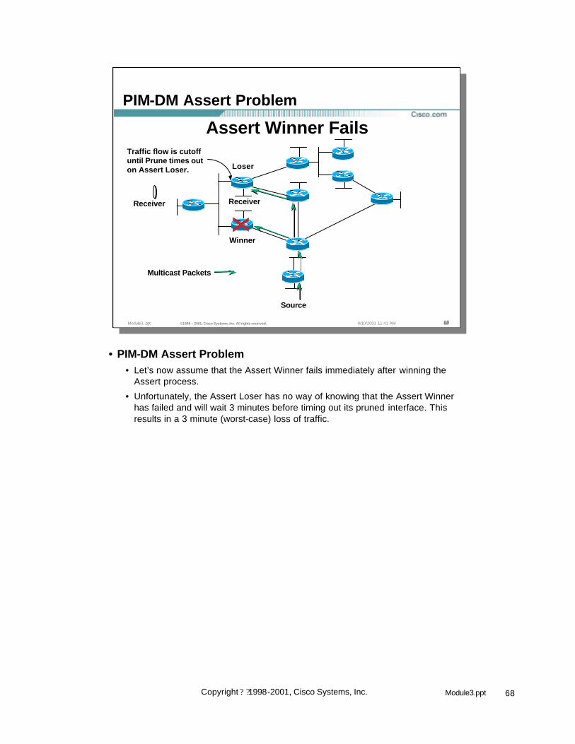
68Module3.pptCopyright ? ?1998-2001, Cisco Systems, Inc.
Module3. ppt ©1998 – 2001, Cisco Systems, Inc. All rights reserved. 6868688/10/2001 11:41 AM
Receiver
Assert Winner Fails
Source
Multicast Packets
PIM-DM Assert Problem
ReceiverX
Loser
Winner
Traffic flow is cutoffuntil Prune times outon Assert Loser.
• PIM-DM Assert Problem• Let’s now assume that the Assert Winner fails immediately after winning the
Assert process.
• Unfortunately, the Assert Loser has no way of knowing that the Assert Winner has failed and will wait 3 minutes before timing out its pruned interface. This results in a 3 minute (worst-case) loss of traffic.

69Module3.pptCopyright ? ?1998-2001, Cisco Systems, Inc.
Module3. ppt ©1998 – 2001, Cisco Systems, Inc. All rights reserved. 6969698/10/2001 11:41 AM
PIM DM Concepts
• PIM Neighbor Discovery• PIM DM State• PIM DM Flooding• PIM DM Pruning• PIM DM Grafting• PIM Assert Mechanism• PIM DM State Maintenance

70Module3.pptCopyright ? ?1998-2001, Cisco Systems, Inc.
Module3. ppt ©1998 – 2001, Cisco Systems, Inc. All rights reserved. 7070708/10/2001 11:41 AM
PIM DM State Maintenance
• State is maintained by the “flood and prune” behavior of Dense mode.– Received Multicast packets reset (S,G) entry
“expiration” timers.– When (S, G) entry “expiration” timers count
down to zero, the entry is deleted.
• Interface prune state times out every 3 minutes causing periodic reflooding and pruning.
• PIM DM State Maintenance• In PIM DM, all (S, G) entries have an expiration countdown timer which is reset
to 3 minutes by the receipt of an (S, G) packet received via the Shortest-Path Tree (SPT). If no further packets are received from the source, this expiration timer goes to zero and the (S, G) entry is deleted.
• When a Prune message is received in PIM Dense mode, the interface on which the Prune was received is marked as “Prune/Dense” and a prune countdown timer is set to 3 minutes. When this timer expires, the interface is set back to “Forward/Dense” and traffic is again flooded out the interface. The downstream router will again send another (S, G) Prune to stop the unwanted traffic; therforethe “Flood and Prune” behaviour occurs every 3 minutes.

71Module3.pptCopyright ? ?1998-2001, Cisco Systems, Inc.
Module3. ppt ©1998 – 2001, Cisco Systems, Inc. All rights reserved. 7171718/10/2001 11:41 AM
PIM Dense Mode Review
Source
Receiver 2Receiver 1
DD FF
II
BB
CC
AA
EE
GG
HH
LinkData
Control
• PIM Dense Mode Review• The following slides will review all the major concepts previously present in a
sample network situation.

72Module3.pptCopyright ? ?1998-2001, Cisco Systems, Inc.
Module3. ppt ©1998 – 2001, Cisco Systems, Inc. All rights reserved. 7272728/10/2001 11:41 AM
PIM Dense Mode Review
Initial Flood of Dataand Creation of State
Source
Receiver 2Receiver 1
DD FF
II
BB
CC
AA
EE
GG
HH
• PIM Dense Mode Review (cont.)• Source starts sending and the (S,G) gets initailly flooded everywhere

73Module3.pptCopyright ? ?1998-2001, Cisco Systems, Inc.
Module3. ppt ©1998 – 2001, Cisco Systems, Inc. All rights reserved. 7373738/10/2001 11:41 AM
PIM Dense Mode Review
Prune to Non-RPF Neighbor
Source
Receiver 2Receiver 1
Prune
DD FF
II
BB
CC
AA
EE
GG
HH
• PIM Dense Mode Review (cont.)• The link between B & C is not C’s RPF interface for this group so a prune is
immediately sent to B and this link is removed off of the tree at B
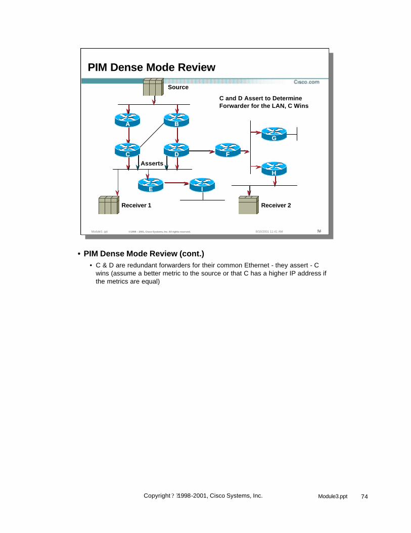
74Module3.pptCopyright ? ?1998-2001, Cisco Systems, Inc.
Module3. ppt ©1998 – 2001, Cisco Systems, Inc. All rights reserved. 7474748/10/2001 11:41 AM
PIM Dense Mode Review
C and D Assert to DetermineForwarder for the LAN, C Wins
Source
Asserts
Receiver 2Receiver 1
DD FF
II
BB
CC
AA
EE
GG
HH
• PIM Dense Mode Review (cont.)• C & D are redundant forwarders for their common Ethernet - they assert - C
wins (assume a better metric to the source or that C has a higher IP address if the metrics are equal)

75Module3.pptCopyright ? ?1998-2001, Cisco Systems, Inc.
Module3. ppt ©1998 – 2001, Cisco Systems, Inc. All rights reserved. 7575758/10/2001 11:41 AM
PIM Dense Mode Review
I Gets PrunedSource
Prune
Receiver 2Receiver 1
DD FF
II
BB
CC
AA
EE
GG
HH
• PIM Dense Mode Review (cont.)• I prunes off - it has no need to receive the group

76Module3.pptCopyright ? ?1998-2001, Cisco Systems, Inc.
Module3. ppt ©1998 – 2001, Cisco Systems, Inc. All rights reserved. 7676768/10/2001 11:41 AM
PIM Dense Mode Review
Source
Receiver 2Receiver 1
DD FF
II
BB
CC
AA
EE
GG
HH
E’s Prune is Ignored
Prune
• PIM Dense Mode Review (cont.)• E prunes but it is ignored since C knows there is a locally attached host via
IGMP state

77Module3.pptCopyright ? ?1998-2001, Cisco Systems, Inc.
Module3. ppt ©1998 – 2001, Cisco Systems, Inc. All rights reserved. 7777778/10/2001 11:41 AM
PIM Dense Mode Review
Source
Receiver 2Receiver 1
DD FF
II
BB
CC
AA
EE
GG
HH
G’s Prune is Overridden
Prune
Join Override
• PIM Dense Mode Review (cont.)• G prunes since it doesn’t need the group
• H overrides the prune since it does need it - F continues to forward on this link
• G will continue to receive the group input on the common Ethernet but since itsoif is NULL, the packets are fast switched to the “bit bucket”

78Module3.pptCopyright ? ?1998-2001, Cisco Systems, Inc.
Module3. ppt ©1998 – 2001, Cisco Systems, Inc. All rights reserved. 7878788/10/2001 11:41 AM
PIM Dense Mode Review
Source
Receiver 2
Receiver 3
Receiver 1
New Receiver, I Sends Graft
Graft
DD FF
II
BB
CC
AA
EE
GG
HH
• PIM Dense Mode Review (cont.)• Assume a new receiver (#3) comes on behnd rtr I
• I grafts onto E
• E already had state for this group sicne it was still being received on the C,D,E Ethernet so it starts sending the group to I

79Module3.pptCopyright ? ?1998-2001, Cisco Systems, Inc.
Module3. ppt ©1998 – 2001, Cisco Systems, Inc. All rights reserved. 7979798/10/2001 11:41 AM
Receiver 3
PIM Dense Mode Review
Source
Receiver 2Receiver 1
I is Grafted back onto tree
DD FF
II
BB
CC
AA
EE
GG
HH
• PIM Dense Mode Review (cont.)• E already had state for this group sicne it was still being received on the C,D,E
Ethernet so it starts sending the group to I
• Final state given all events in the network
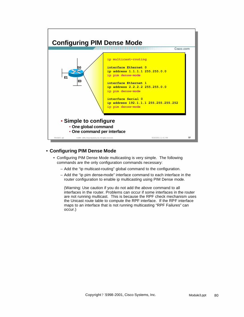
80Module3.pptCopyright ? ?1998-2001, Cisco Systems, Inc.
Module3. ppt ©1998 – 2001, Cisco Systems, Inc. All rights reserved. 8080808/10/2001 11:41 AM
Configuring PIM Dense Mode
E1E0
S0
ip multicastip multicast--routingrouting
interface Ethernet 0ip address 1.1.1.1 255.255.0.0ipip pimpim densedense--modemode
interface Ethernet 1ip address 2.2.2.2 255.255.0.0ipip pimpim densedense--modemode
interface Serial 0ip address 192.1.1.1 255.255.255.252ipip pimpim densedense--modemode
• Simple to configure• One global command• One command per interface
• Configuring PIM Dense Mode• Configuring PIM Dense Mode multicasting is very simple. The following
commands are the only configuration commands necessary:
– Add the “ip multicast-routing” global command to the configuration.
– Add the “ip pim dense-mode” interface command to each interface in the router configuration to enable ip multicasting using PIM Dense mode.
(Warning: Use caution if you do not add the above command to allinterfaces in the router. Problems can occur if some interfaces in the router are not running multicast. This is because the RPF check mechanism uses the Unicast route table to compute the RPF interface. If the RPF interface maps to an interface that is not running multicasting “RPF Failures” can occur.)

81Module3.pptCopyright ? ?1998-2001, Cisco Systems, Inc.
Module2. ppt ©1998 – 2001, Cisco Systems, Inc. All rights reserved. 81