qs1 technical reference manual - joe kleinjoeklein.cc/page/est-class/pdfs/3100184 r05 qs1... · qs1...
TRANSCRIPT

QS1
Technical Reference Manual
P/N 3100184 • REV 05 • REB 14FEB13
DEVELOPED BY UTC Fire & Security 8985 Town Center Parkway Bradenton, FL 34202 (941) 739-4200
COPYRIGHT NOTICE © 2013 UTC Fire & Security. All rights reserved.
This manual is copyrighted by UTC Fire & Security. (UTCFS). You may not reproduce, translate, transcribe, or transmit any part of this manual without express, written permission from UTC Fire & Security.
This manual contains proprietary information intended for distribution to authorized persons or companies for the sole purpose of conducting business with UTC Fire & Security. Unauthorized distribution of the information contained in this manual may violate the terms of the distribution agreement.
DISCLAIMER The information contained in this manual has been thoroughly reviewed for errors and is presumed to be correct. As such, UTC Fire & Security is not responsible for any errors or inaccuracies and reserves the right to make changes to the documentation without notice.
TRADEMARKS HyperTerminal is a registered trademark of Hilgraeve, Inc. Windows is a trademark of Microsoft Corporation.

QS1 Technical Reference Manual i
Content
Chapter 1 Introduction • 1.1 About this manual • 1.2 Fire alarm system limitations • 1.3 Limitation of liability • 1.4 FCC compliance statement • 1.5 Industry Canada information • 1.7 Related documentation • 1.8
Chapter 2 Product description • 2.1 General description • 2.3 Minimum system requirements • 2.10 System status indicators • 2.11 Operator controls and indicators • 2.12 Optional controls and indicators • 2.14 Alphanumeric display • 2.16 Command menu organization • 2.19 Command descriptions • 2.24 Event messages • 2.28 Control panel operation • 2.31
Chapter 3 Panel components • 3.1 PS6 Power Supply Card • 3.3 SLIC Signature Loop Interface Controller • 3.11 ZR8 Relay Card • 3.19 DLD Dual Line Dialer Card • 3.22 NT-A (RS-485 card with QS-232 module) • 3.27 LED/switch cards • 3.30
Chapter 4 Accessories • 4.1 CDR-3 Bell Coder • 4.2 RPM Reverse Polarity Module • 4.8 CTM City Tie Module • 4.12 IOP3A RS-232 Isolator • 4.14
Chapter 5 Operating instructions • 5.1 Logging on to the control panel • 5.2 Viewing status reports • 5.3 Viewing maintenance reports • 5.4 Viewing a history report • 5.5 Viewing alarm history reports • 5.6 Performing a lamp test • 5.7 Silencing the panel buzzer • 5.8 Resetting the fire alarm system • 5.9 Silencing alarm signals • 5.10 Sounding an alarm • 5.11 Disabling and enabling zones • 5.12

Content
ii QS1 Technical Reference Manual
Disabling and enabling device addresses • 5.13 Switching detector alarm sensitivity • 5.14 Switching event message routes • 5.15 Changing the level 1 password • 5.16 Restarting the fire alarm system • 5.17
Chapter 6 Installation • 6.1 Installation overview • 6.2 Mounting the control panel backbox • 6.4 Pulling cables into the backbox • 6.6 Installing panel components • 6.8 Installing the PS6 card • 6.9 Installing the front panel • 6.10 Connecting mains AC • 6.13 Installing standby batteries • 6.14 Installing a QSA series remote annunciator • 6.15 System startup procedure • 6.22 Connecting peripheral devices • 6.27 Connecting auxiliary/booster power supplies • 6.29 Installation requirements for UL 864 signal
synchronization • 6.31
Chapter 7 Front panel programming • 7.1 UL 864 programming requirements • 7.2 Before you begin • 7.4 Device type descriptions • 7.9 Programming limits • 7.13 Changing level 3 and level 4 passwords • 7.14 Configuring the system automatically • 7.15 Configuring the system • 7.16 Configuring SLIC cards • 7.21 Configuring addressable detectors • 7.25 Configuring addressable modules • 7.27 Configuring DLD cards • 7.37 Configuring receiver accounts • 7.40 Configuring output groups • 7.47 Configuring zones • 7.59 Clearing the history log • 7.65 Saving the project database • 7.66
Chapter 8 Service and troubleshooting • 8.1 Display or print a revision report • 8.2 Starting and canceling a service group test • 8.3 Disabling and enabling AND groups • 8.4 Disabling and enabling matrix groups • 8.5 Disabling and enabling time controls • 8.6 Disabling and enabling switches • 8.7 Disabling and enabling option cards • 8.8 Turning an output on and off • 8.9 Turning an LED on and off • 8.11 Setting the system time and date • 8.13 Changing the level 2 password • 8.14 Clearing trouble messages • 8.15 Replacing the control panel fuse • 8.20
Content
QS1 Technical Reference Manual iii
Using HyperTerminal • 8.21
Appendix A System calculations • A.1 Notification appliance circuit calculations • A.2 Intelligent addressable loop maximum wire length • A.8 Battery calculations • A.14
Appendix B Barcode library • B.1
Appendix C Addresses • C.1 System addresses • C.2 CPU card addresses • C.4 PS6 card addresses • C.6 SLIC card addresses • C.7 ZR8 card addresses • C.8 DLD card addresses • C.9 LED/switch card addresses • C.10
Appendix D Contact ID event codes • D.1 Alarms • D.2 Supervisories • D.3 Troubles • D.4 Bypasses/disables • D.8 Test/miscellaneous • D.10
Z Index • Z.1

Content
iv QS1 Technical Reference Manual
List of figures
Figure 2-1: Fire alarm control panel front view • 2.4 Figure 2-2: QSA series remote annunciator front view • 2.6 Figure 2-3: SRA1 front view • 2.7 Figure 2-4: R Series remote annunciators • 2.8 Figure 3-1: PS6 card, front view • 3.3 Figure 3-2: Relay output wiring • 3.5 Figure 3-3: Smoke/accessory power output wiring • 3.6 Figure 3-4: RS-485 port wiring • 3.7 Figure 3-5: RS-232 port wiring • 3.7 Figure 3-6: AUX power output wiring • 3.8 Figure 3-7: Standby battery wiring • 3.9 Figure 3-8: PS6 card jumpers • 3.10 Figure 3-9: SLIC card front view • 3.11 Figure 3-10: SLIC card NAC wiring • 3.13 Figure 3-11: Intelligent addressable loop wiring • 3.14 Figure 3-12: SLIC card address switch settings • 3.15 Figure 3-13: SLIC card jumpers • 3.16 Figure 3-14: Two-wire smoke detector application wiring • 3.18 Figure 3-15: ZR8 card, front view • 3.19 Figure 3-16: ZR8 card wiring • 3.20 Figure 3-17: ZR8 card address switch settings • 3.20 Figure 3-18: ZR8 card jumpers • 3.21 Figure 3-19: DLD card, front view • 3.22 Figure 3-20: DLD card wiring • 3.26 Figure 3-21: RS-485 card, front view • 3.27 Figure 3-22: RS-485 card jumpers • 3.28 Figure 3-23: RS-485 card wiring • 3.29 Figure 3-24: SL30 card, front view • 3.31 Figure 3-25: SL30-1 card, front view • 3.31 Figure 3-26: SL30L card, front view • 3.32 Figure 3-27: SL20L5S card, front view • 3.33 Figure 4-1: CDR-3, front view • 4.2 Figure 4-2: CDR-3 jumper settings • 4.5 Figure 4-3: Typical CDR-3 application wiring diagram • 4.7 Figure 4-4: RPM, front view • 4.8 Figure 4-5: RPM wiring diagram (new style) • 4.10 Figure 4-6: RPM wiring diagram (old style) • 4.11 Figure 4-7: CTM, front view • 4.12 Figure 4-8: CTM application wiring diagram • 4.13 Figure 4-9: IOP3A, front view • 4.14 Figure 4-10: IOP3A jumper settings • 4.14 Figure 4-11: IOP3A switch settings • 4.15 Figure 4-12: IOP3A application wiring diagram • 4.17 Figure 6-1: Control panel backbox mounting diagram • 6.4 Figure 6-2: Backbox dimensions for a QS1-1-(G/R)-1 • 6.5 Figure 6-3: Typical cable entry locations • 6.7 Figure 6-4: Cabinet layout diagram • 6.8 Figure 6-5: Power supply card installation • 6.9
Content
QS1 Technical Reference Manual v
Figure 6-6: Cabinet door assembly • 6.10 Figure 6-7: Front panel assembly • 6.11 Figure 6-8: Front panel ribbon cable connections • 6.12 Figure 6-9: Mains AC wiring diagram • 6.13 Figure 6-10: Standby battery installation • 6.14 Figure 6-11: Remote annunciator backbox mounting
diagram • 6.16 Figure 6-12: QSA-1-S and QSA-1-F backbox dimensions • 6.17 Figure 6-13: RAI card installation • 6.18 Figure 6-14: Remote annunciator door installation • 6.19 Figure 6-15: Remote annunciator CPU/Display Unit and
LED/switch card installation • 6.19 Figure 6-16: Key switch ground strap connection • 6.20 Figure 6-17: Remote annunciator ribbon cable
connections • 6.20 Figure 6-18: RAI card power wiring • 6.21 Figure 6-19: RAI card data wiring • 6.21 Figure 6-20: Computer connection to the RS-232
terminals • 6.27 Figure 6-21: Serial printer connection diagram • 6.28 Figure 6-22: Typical booster power supply wiring • 6.30 Figure 6-23: Typical SLIC card NAC wiring • 6.32 Figure 6-24: Loop wiring for system signal synchronization • 6.33 Figure 6-25: Loop wiring for notification circuit signal
synchronization • 6.33 Figure 6-26: Typical SIGA-CC1S NAC wiring • 6.34 Figure 6-27: Typical SIGA-CC1 NAC wiring • 6.35 Figure 7-1: Combining common responses in the same output
group • 7.5 Figure 7-2: Combining response types in the same output
group • 7.6 Figure 7-3: Combining mutually exclusive responses in the same
output group • 7.6 Figure 7-4: System configuration diagram • 7.19 Figure 7-5: SLIC card configuration diagram • 7.29 Figure 7-6: DLD card configuration • 7.42 Figure 7-7: Output group configuration • 7.50 Figure 7-8: Zone configuration • 7.61 Figure 8-1: Example revision report • 8.2
Content
vi QS1 Technical Reference Manual
List of tables
Table 2-1: Control panel models • 2.4 Table 2-2: Control panel option cards • 2.5 Table 2-3: QSA series remote annunciators • 2.6 Table 2-4: R Series remote annunciators • 2.8 Table 2-5: Control panel accessories • 2.9 Table 2-6: Minimum system requirements • 2.10 Table 2-7: System status indicator descriptions • 2.11 Table 2-8: Operator controls and indicator descriptions • 2.12 Table 2-9: Optional control and indicator descriptions • 2.14 Table 2-10: Level 1 command menus • 2.19 Table 2-11: Level 2 command menus • 2.20 Table 2-12: Level 3 command menus • 2.21 Table 2-13: Level 4 command menus • 2.22 Table 6-1: Suggested LED/switch card arrangements • 6.11 Table 6-2: Installation requirements for UL 864 signal
synchronization • 6.31 Table 7-1: Front panel and software configuration utility
programming limits • 7.13 Table 7-3: Default system settings • 7.18 Table 7-5: Factory default settings for addressable
devices • 7.24 Table 8-1: Trouble messages • 8.15 Table A-1: Typical wire resistances • A.5 Table A-2: Maximum amount of wire you can use to construct an
intelligent addressable loop • A.8 Table A-3: Longest allowable circuit path with 0 SIGA-UMs or
SIGA-MABs configured for 2-wire smoke detectors • A.10
Table A-4: Longest allowable circuit path with 1 to 5 SIGA-UMs or SIGA-MABs configured for 2-wire smoke detectors • A.11
Table A-5: Longest allowable circuit path with 6 to 10 SIGA-UMs or SIGA-MABs configured for 2-wire smoke detectors • A.12
Table A-6: Longest allowable circuit path with 11 to 15 SIGA-UMs or SIGA-MABs configured for 2-wire smoke detectors • A.13
Table A-7: Control panel current load worksheet • A.15 Table A-8: Smoke/accessory power current load worksheet • A.16 Table A-9: AUX power current load worksheet • A.17 Table C-1: System device addresses • C.2 Table C-1: System device addresses (continued) • C.3 Table C-2: CPU card addresses • C.4 Table C-2: CPU card addresses (continued) • C.5 Table C-3: PS6 card addresses • C.6 Table C-4: SLIC card addresses • C.7 Table C-5: ZR8 card addresses • C.8 Table C-6: DLD card addresses • C.9
Content
QS1 Technical Reference Manual vii
Table C-7: Annunciator card group 1 addresses • C.10 Table C-8: Annunciator card group 2 addresses • C.13 Table C-9: Annunciator card group 3 addresses • C.17 Table C-10: Annunciator card group 4 addresses • C.21 Table C-11: Annunciator card group 5 addresses • C.25 Table C-12: Annunciator card group 6 addresses • C.28 Table C-13: Annunciator card group 7 addresses • C.32 Table C-14: Annunciator card group 8 addresses • C.36 Table C-15: Annunciator card group 9 addresses • C.40 Table C-16: Annunciator card group 10 addresses • C.43 Table C-17: Annunciator card group 11 addresses • C.47 Table C-18: Annunciator card group 12 addresses • C.51 Table C-19: Annunciator card group 13 addresses • C.54 Table C-20: Annunciator card group 14 addresses • C.58 Table C-21: Annunciator card group 15 addresses • C.62 Table C-22: Annunciator card group 16 addresses • C.66

Content
viii QS1 Technical Reference Manual
QS1 Technical Reference Manual 1.1
Chapter 1 Introduction
Summary
This chapter provides information about this manual and other related documentation.
Content
About this manual • 1.2 Fire alarm system limitations • 1.3 Limitation of liability • 1.4 FCC compliance statement • 1.5
Subpart B of Part 15 • 1.5 Part 68 • 1.5
Industry Canada information • 1.7 Related documentation • 1.8
Introduction
1.2 QS1 Technical Reference Manual
About this manual This manual provides information on how to install, program, and operate a QuickStart single loop intelligent addressable life safety control panel. It is organized as follows:
Chapter 1, Introduction: Provides information about this manual and other related documentation.
Chapter 2, Product description: Provides technical descriptions of the control panel and its operation. It also provides descriptions of the command menus.
Chapter 3, Panel components: Provides technical descriptions of the components that can be connected to the control panel.
Chapter 4, Accessories: Provides technical descriptions of the accessories that can be connected to control panel.
Chapter 5, Operating instructions: Provides instructions for operating the fire alarm system from the control panel CPU/Display Unit. It is intended for those who might be expected to operate the control panel in a fire alarm emergency.
Chapter 6, Installation: Provides instructions for installing the fire alarm system. It is intended for trained installers who are familiar with all applicable codes and regulations.
Chapter 7, Front panel programming: Provides instructions for programming the fire alarm system from the control panel CPU/Display Unit. It is intended for those trained and authorized to program the fire alarm system.
Chapter 8, Service and troubleshooting: Provides instructions for servicing and troubleshooting the fire alarm system. It is intended for those trained and authorized to maintain the fire alarm system.
Appendix A, System calculations: Provides worksheets for sizing standby batteries, and for calculating the maximum wire lengths for notification appliance circuits and intelligent addressable loops.
Appendix B, Barcode library: Provides a set of barcodes that you can use to add location descriptions to event messages from the control panel CPU/Display Unit.
Appendix C, Addresses: Provides a comprehensive list of addresses to use as a general reference.
Appendix D, Contact ID event codes: Provides a complete list of Contact ID event codes that you can use when programming dialer strings.
Introduction
QS1 Technical Reference Manual 1.3
Fire alarm system limitations The purpose of an automatic fire alarm system is to provide early detection and warning of a developing fire. There are a number of uncontrollable factors that can prevent or severely limit the ability of an automatic fire alarm system to provide adequate protection. As such, an automatic fire alarm system cannot guarantee against loss of life or loss of property.
Two main causes of system failures are improper installation and poor maintenance. The best way to minimize these types of system failures is to have only trained fire alarm system professionals design, install, test, and maintain your fire alarm system in accordance with national and local fire codes.
Fire alarm systems will not operate without electrical power. As fires frequently cause power interruption, we suggest that you discuss ways to safeguard the electrical system with your local fire protection specialist.
Introduction
1.4 QS1 Technical Reference Manual
Limitation of liability This product has been designed to meet the requirements of NFPA Standard 72; Underwriters Laboratories, Inc., Standard 864; and Underwriters Laboratories of Canada, Inc., Standard ULC S527. Installation in accordance with this manual, applicable codes, and the instructions of the Authority Having Jurisdiction is mandatory.
UTCFS shall not under any circumstances be liable for any incidental or consequential damages arising from loss of property or other damages or losses owing to the failure of UTCFS products beyond the cost of repair or replacement of any defective products. UTCFS reserves the right to make product improvements and change product specifications at any time.
Introduction
QS1 Technical Reference Manual 1.5
FCC compliance statement
Subpart B of Part 15
This equipment can generate and radiate radio frequency energy. If this equipment is not installed in accordance with this manual, it may cause interference to radio communications. This equipment has been tested and found to comply within the limits for Class A computing devices pursuant to Subpart B of Part 15 of the FCC rules. These rules are designed to provide reasonable protection against such interference when this equipment is operated in a commercial environment. Operation of this equipment is likely to cause interference, in which case the user, at their expense, will be required to take whatever measures necessary to correct the interference.
Part 68
The DLD card complies with Part 68 of the FCC rules. The DLD card’s FCC registration number and the ringer equivalence number (REN) are on the back of the DLD card. This information must be provided to the telephone company, if requested.
The DLD card connects to the public switched telephone network using an RJ31X or RJ38X jack, which must also comply with FCC Part 68 rules.
The REN is used to determine the quantity of devices that may be connected to the telephone line. Excessive RENs on the telephone line may result in the devices not ringing in response to an incoming call. In most, but not all areas, the sum of RENs should not exceed five (5). To be certain the number of devices that may be connected to a line, as determined by the total RENs, contact the local telephone company.
If the DLD card causes harm to the telephone network, the telephone company will notify you in advance that temporary discontinuance of service may be required. If advance notice is not practical, the telephone company will notify you as soon as possible. You will also be advised of your right to file a complaint with the FCC, if you believe it is necessary.
The telephone company may make changes in its facilities, equipment, operations, or procedures that could affect the operation of the DLD card. If this happens, the telephone company will provide advance notice in order for you to make necessary modifications to maintain uninterrupted service.
Introduction
1.6 QS1 Technical Reference Manual
If trouble is experienced with the DLD card, for repair or warranty information, contact:
UTC Fire & Security 8985 Town Center Parkway Bradenton, Florida, USA 34202 Telephone: 1-800-655-4497
If the DLD is causing harm to the telephone network, the telephone company may request that you disconnect the DLD until the problem is resolved.
The DLD card contains no user-serviceable parts. It must be returned to the factory for repairs.
The DLD card can’t be used on a public coin telephone or party line service provided by the telephone company.
Introduction
QS1 Technical Reference Manual 1.7
Industry Canada information Note: The Industry Canada label identifies certified equipment. This certification means that the equipment meets certain telecommunications network protective, operational, and safety requirements. Industry Canada does not guarantee the equipment will operate to the user’s satisfaction.
Before installing this equipment, users should ensure that it is permissible to be connected to the facilities of the local telecommunications company. The equipment must also be installed using an acceptable method of connection. The customer should be aware that compliance with the above conditions may not prevent degradation of service in some situations.
Repairs to certified equipment should be coordinated by a representative designated by the supplier. Any repairs or alterations made by the user to this equipment, or equipment malfunctions, may give the telecommunications company cause to request the user disconnect the equipment.
Users should ensure for their own protection that the electrical ground connections of the power utility, telephone lines, and internal metallic water pipe system, if present, are connected together. This precaution may be particularly important in rural areas.
Caution: Users should not attempt to make such connections themselves, but should contact the appropriate electric inspection authority, or electrician, as appropriate.
Note: The ringer equivalence number (REN) assigned to each terminal device provides an indication of the maximum number of terminals allowed to be connected to a telephone interface. The termination on an interface may consist of any combination of devices subject only to the requirement that the sum of the ringer equivalence numbers of all the devices does not exceed five.
Introduction
1.8 QS1 Technical Reference Manual
Related documentation
National Fire Protection Association 1 Batterymarch Park P.O. Box 9101 Quincy, MA 02269-9101
NFPA 11 Low-Expansion Foam Systems
NFPA 11A Medium- and High-Expansion Foam Systems
NFPA 12 Carbon Dioxide Extinguishing Systems
NFPA 13 Sprinkler Systems
NFPA 15 Water Spray Fixed Systems for Fire Protection
NFPA 16 Deluge Foam-Water Sprinkler and Foam-Water Spray Systems
NFPA 17 Dry Chemical Extinguishing Systems
NFPA 70 National Electric Code
NFPA 72 National Fire Alarm Code
Underwriters Laboratories, Inc. 333 Pfingsten Road Northbrook, IL 60062-2096
UL 38 Manually Actuated Signaling Boxes
UL 217 Smoke Detectors, Single & Multiple Station
UL 228 Door Closers/Holders for Fire Protective Signaling Systems
UL 268 Smoke Detectors for Fire Protective Signaling Systems
UL 268A Smoke Detectors for Duct Applications
UL 346 Waterflow Indicators for Fire Protective Signaling Systems
UL 464 Audible Signaling Appliances
UL 521 Heat Detectors for Fire Protective Signaling Systems
UL 864 Standard for Control Units for Fire Protective Signaling Systems
UL 1481 Power Supplies for Fire Protective Signaling Systems
UL 1638 Visual Signaling Appliances
UL 1971 Visual Signaling Appliances
Underwriters Laboratories of Canada 7 Crouse Road Scarborough, ON Canada M1R 3A9
CSA C22.1-02 Canadian Electrical Code, Part 1
ULC-S524 Standard for the Installation of Fire Alarm Systems
ULC-S527 Standard for Control Units for Fire Alarm Systems
ULC-S536 Standard for the Inspection and Testing of Fire Alarm Systems
ULC-S537 Standard for the Verification of Fire Alarm Systems
ULC/ ORD-C693-1994 Central Station Fire Protective Signaling System and Services
Introduction
QS1 Technical Reference Manual 1.9
UTC Fire & Security 8985 Town Center Parkway Bradenton, FL 34202
CTM City Tie Module Installation Sheet (P/N 3101025)
CDR-3 Bell Coder Installation Sheet (P/N 3100023)
DLD Dual Inline Dialer Installation Sheet (P/N 3100187)
IOP3A Isolator RS-232 Card Installation Sheet (P/N 270758)
PS6 Power Supply Card Installation Sheet (P/N 3100201)
QSA-1(X), QSA-2(X) Remote Annunciator Cabinet Installation Sheet (P/N 3100295)
QS-CPU(X) CPU/Display Unit Installation Sheet (P/N 3100276)
SL30, SL30-1, SL30L, SL20L5S LED/Switch Card Installation Sheet (P/N 3100193)
SLIC Signature Intelligent Controller Card Installation Sheet (P/N 3100192)
RS485 (NT-A) Card and QS-232 UART Module Installation Sheet (P/N 3100191)
ZA8-2 Class A Zone Card Installation Sheet (P/N 3100189)
ZB16-4 Class B Zone Card Installation Sheet (P/N 3100188)
ZR8 Relay Card Installation Sheet (P/N 3100190)
Signature Series Intelligent Smoke and Heat Detectors Applications Bulletin (P/N 270145)
Signature Series Component Installation Manual (P/N 270497)
EST Strobe Applications Guide (P/N 85000-0049)
QuickStart Online Help Utility (P/N 7350047)
QuickStart ULI and ULC Compatibility Lists (P/N 3100335)

Introduction
1.10 QS1 Technical Reference Manual

QS1 Technical Reference Manual 2.1
Chapter 2 Product description
Summary
This chapter provides technical descriptions of the control panel and its operation. It also provides descriptions of the command menus.
Content
General description • 2.3 System hardware capabilities • 2.3 Programmable features • 2.3 Control panel • 2.4 Option cards • 2.5 QSA series remote annunciators • 2.5 SRA1 remote annunciators • 2.7 R Series remote annunciators • 2.7 Envoy graphic annunciators • 2.9 Accessories • 2.9
Minimum system requirements • 2.10 System status indicators • 2.11 Operator controls and indicators • 2.12 Optional controls and indicators • 2.14 Alphanumeric display • 2.16
System Normal display screen • 2.16 Event Message display screen • 2.16 Details display screen • 2.17
Command menu organization • 2.19 Level 1 command menus • 2.19 Level 2 command menus • 2.19 Level 3 command menus • 2.20 Level 4 command menus • 2.22
Command descriptions • 2.24 Main menu • 2.24 Status menu • 2.24 Reports menu • 2.24 Test menu • 2.26 Enable menu • 2.26 Disable menu • 2.27 Activate menu • 2.27 Restore menu • 2.27
Event messages • 2.28 Event message queues • 2.28 Alarm event messages • 2.28 Supervisory event messages • 2.29 Trouble event messages • 2.29 Monitor event messages • 2.30
Control panel operation • 2.31

Product description
2.2 QS1 Technical Reference Manual
Normal state • 2.31 Alarm state • 2.31 Supervisory state • 2.32 Trouble state • 2.32 Monitor state • 2.33 Disable state • 2.34 Test state • 2.35
Product description
QS1 Technical Reference Manual 2.3
General description This topic provides a general description of the system hardware capabilities, control panel, electronic subassemblies, and remote annunciator panels.
System hardware capabilities
System hardware capabilities vary with cabinet size and hardware configuration but generally include:
• One Class A or Class B intelligent addressable loop with up to 250 devices
• Two Class A or Class B notification appliance circuits (NACs)
• One LED/switch card
• An alphanumeric display that provides supplemental information related to the current functional condition of the fire alarm system
• Up to 8 programmable dry contact relays
• Up to 4.5 amps of 24 Vfwr (full wave rectified) power for operating notification appliances
• A battery charger circuit capable of charging standby batteries rated up to 40 Ah. Maximum battery size for ULC applications is 30 Ah.
• Up to eight fully supervised mirrored or customized remote annunciators
Programmable features
The fire alarm system includes a number of programmable features as listed below.
• Zones • Service groups • AND groups • Matrix groups • Custom event messages • User labels • Automatic alarm signal silence timer • Alarm signal silence/reset inhibit timer • AC power fault delay timer • Panel silence resound timer • Waterflow silence • Zone resound inhibit • Two-stage timer • Fault reminder
Product description
2.4 QS1 Technical Reference Manual
• Message routing • Message filtering • Time controls
Control panel
The control panel consists of a cabinet backbox and door, a transformer, a PS6 power supply card, a SLIC card, and a CPU/Display Unit. The cabinet, PS6 card, the SLIC card, and CPU/Display Unit are assembled in the field. Optionally, the control panel can include one single-space option card and one LED/switch card.
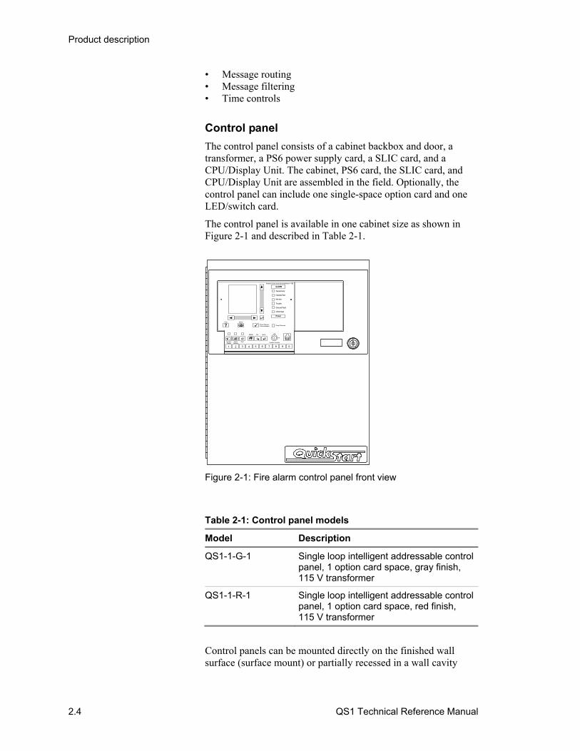
The control panel is available in one cabinet size as shown in Figure 2-1 and described in Table 2-1.
1 2 3 4 6 7 8 9 05
ALARM
Supervisory
CPU Fault
Ground Fault
Trouble
Disable/Test
Monitor
Power
PRESS ZONE FOR INFORMATION
SystemReset
AlarmSilence
Help Status
Panel Silenced
Off
On
Enable Controls
MENU Del Enter
Panel Silence/Acknowledged
Drill
Figure 2-1: Fire alarm control panel front view
Table 2-1: Control panel models
Model Description
QS1-1-G-1 Single loop intelligent addressable control panel, 1 option card space, gray finish, 115 V transformer
QS1-1-R-1 Single loop intelligent addressable control panel, 1 option card space, red finish, 115 V transformer
Control panels can be mounted directly on the finished wall surface (surface mount) or partially recessed in a wall cavity
Product description
QS1 Technical Reference Manual 2.5
(semiflush mount). Semiflush mounted cabinets may require a trim ring kit, ordered separately.
Option cards
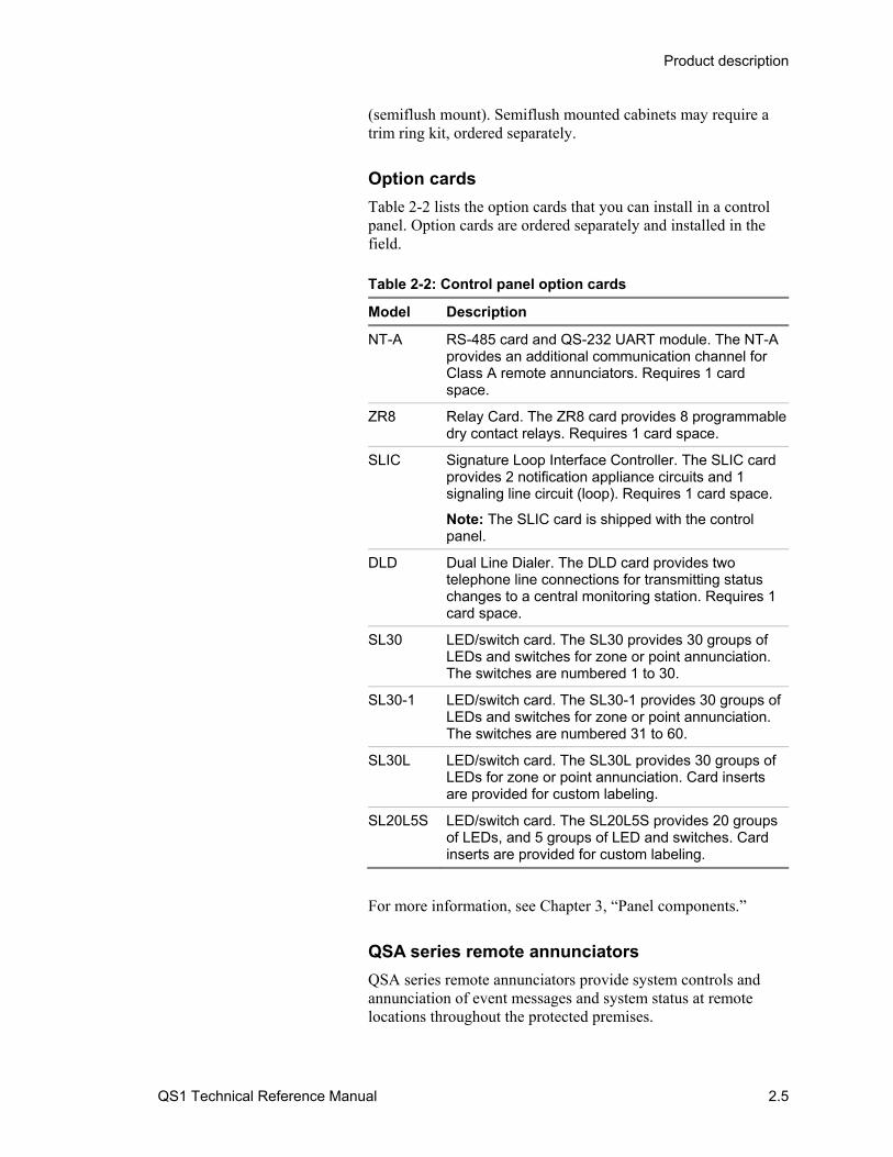
Table 2-2 lists the option cards that you can install in a control panel. Option cards are ordered separately and installed in the field. Table 2-2: Control panel option cards
Model Description
NT-A RS-485 card and QS-232 UART module. The NT-A provides an additional communication channel for Class A remote annunciators. Requires 1 card space.
ZR8 Relay Card. The ZR8 card provides 8 programmable dry contact relays. Requires 1 card space.
SLIC Signature Loop Interface Controller. The SLIC card provides 2 notification appliance circuits and 1 signaling line circuit (loop). Requires 1 card space.
Note: The SLIC card is shipped with the control panel.
DLD Dual Line Dialer. The DLD card provides two telephone line connections for transmitting status changes to a central monitoring station. Requires 1 card space.
SL30 LED/switch card. The SL30 provides 30 groups of LEDs and switches for zone or point annunciation. The switches are numbered 1 to 30.
SL30-1 LED/switch card. The SL30-1 provides 30 groups of LEDs and switches for zone or point annunciation. The switches are numbered 31 to 60.
SL30L LED/switch card. The SL30L provides 30 groups of LEDs for zone or point annunciation. Card inserts are provided for custom labeling.
SL20L5S LED/switch card. The SL20L5S provides 20 groups of LEDs, and 5 groups of LED and switches. Card inserts are provided for custom labeling.
For more information, see Chapter 3, “Panel components.”
QSA series remote annunciators
QSA series remote annunciators provide system controls and annunciation of event messages and system status at remote locations throughout the protected premises.
Product description
2.6 QS1 Technical Reference Manual
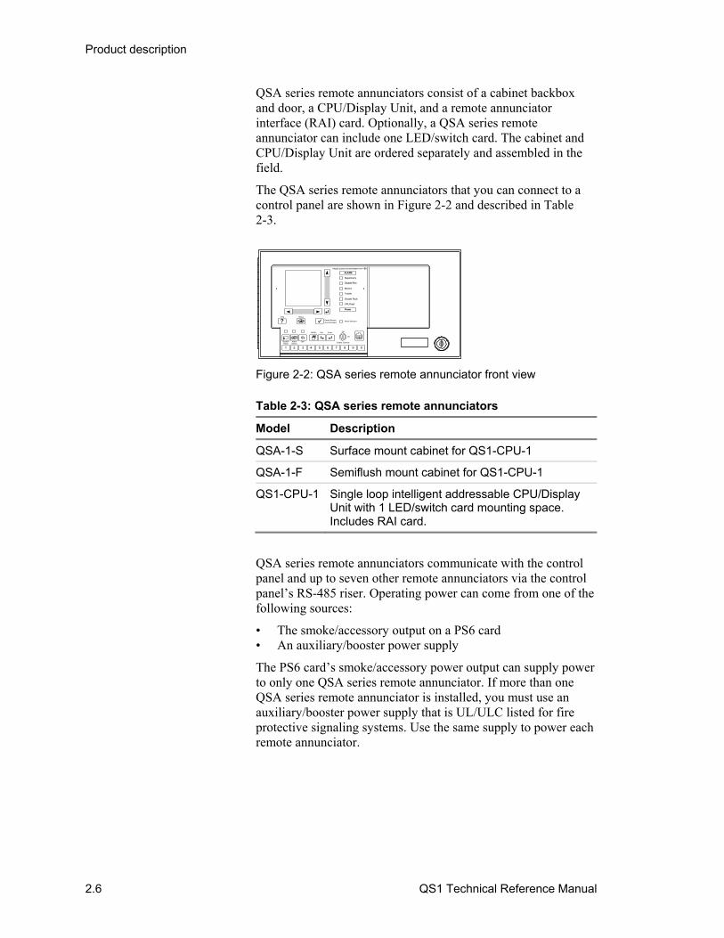
QSA series remote annunciators consist of a cabinet backbox and door, a CPU/Display Unit, and a remote annunciator interface (RAI) card. Optionally, a QSA series remote annunciator can include one LED/switch card. The cabinet and CPU/Display Unit are ordered separately and assembled in the field.
The QSA series remote annunciators that you can connect to a control panel are shown in Figure 2-2 and described in Table 2-3.
1 2 3 4 6 7 8 9 05
ALARM
Supervisory
CPU Fault
Ground Fault
Trouble
Disable/Test
Monitor
Power
PRESS ZONE FOR INFORMATION
SystemReset
AlarmSilence
Help Status
Panel Silenced
Off
On
Enable Controls
MENU Del Enter
Panel Silence/Acknowledged
Drill
Figure 2-2: QSA series remote annunciator front view
Table 2-3: QSA series remote annunciators
Model Description
QSA-1-S Surface mount cabinet for QS1-CPU-1
QSA-1-F Semiflush mount cabinet for QS1-CPU-1
QS1-CPU-1 Single loop intelligent addressable CPU/Display Unit with 1 LED/switch card mounting space. Includes RAI card.
QSA series remote annunciators communicate with the control panel and up to seven other remote annunciators via the control panel’s RS-485 riser. Operating power can come from one of the following sources:
• The smoke/accessory output on a PS6 card • An auxiliary/booster power supply
The PS6 card’s smoke/accessory power output can supply power to only one QSA series remote annunciator. If more than one QSA series remote annunciator is installed, you must use an auxiliary/booster power supply that is UL/ULC listed for fire protective signaling systems. Use the same supply to power each remote annunciator.
Product description
QS1 Technical Reference Manual 2.7
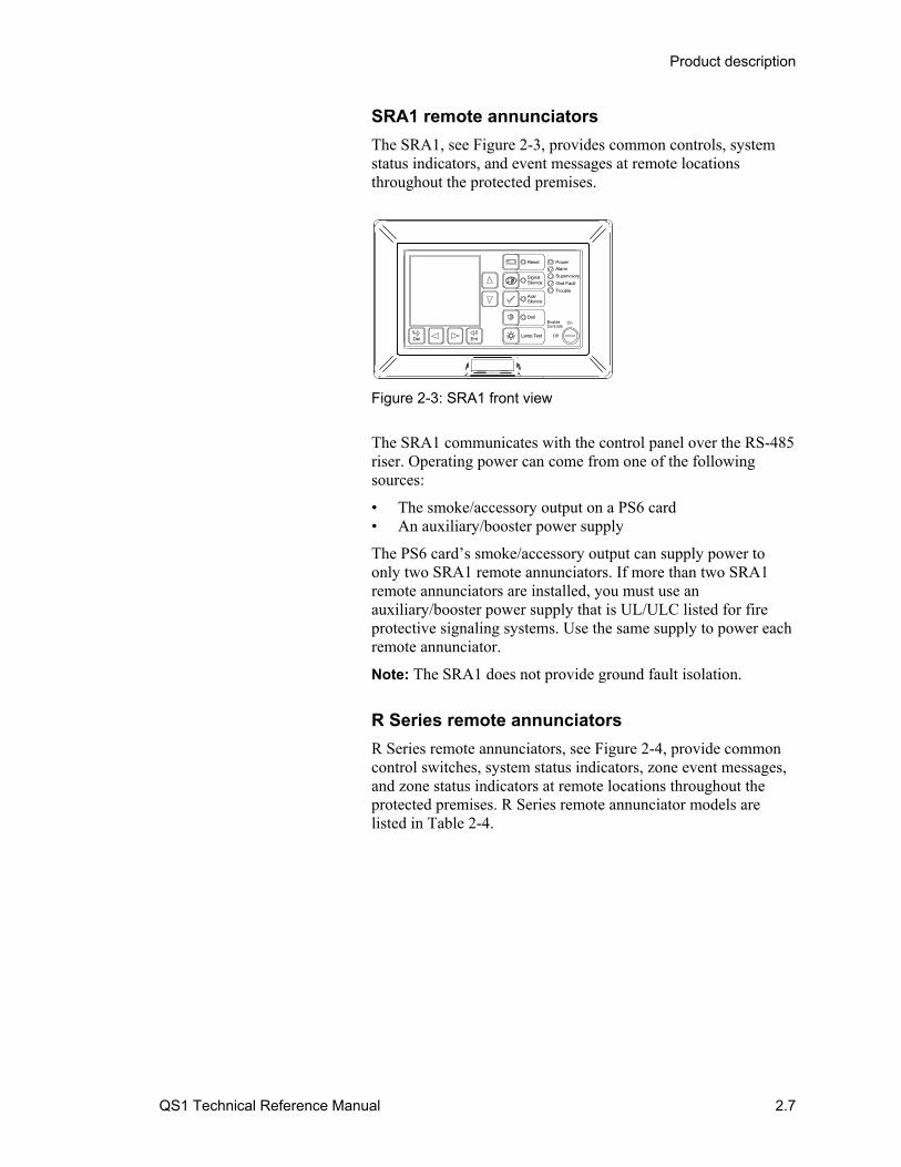
SRA1 remote annunciators
The SRA1, see Figure 2-3, provides common controls, system status indicators, and event messages at remote locations throughout the protected premises.
Del Ent
Reset
SignalSilence
Ack/Silence
Drill
Lamp Test
Power
Alarm
Supervisory
Gnd Fault
Trouble
EnableControls
On
Off
Figure 2-3: SRA1 front view
The SRA1 communicates with the control panel over the RS-485 riser. Operating power can come from one of the following sources:
• The smoke/accessory output on a PS6 card • An auxiliary/booster power supply
The PS6 card’s smoke/accessory output can supply power to only two SRA1 remote annunciators. If more than two SRA1 remote annunciators are installed, you must use an auxiliary/booster power supply that is UL/ULC listed for fire protective signaling systems. Use the same supply to power each remote annunciator.
Note: The SRA1 does not provide ground fault isolation.
R Series remote annunciators
R Series remote annunciators, see Figure 2-4, provide common control switches, system status indicators, zone event messages, and zone status indicators at remote locations throughout the protected premises. R Series remote annunciator models are listed in Table 2-4.

Product description
2.8 QS1 Technical Reference Manual
Controls Enabled
Ack/Silence
Reset
Signal Silence
Drill
Lamp Test
PowerFire AlarmSupervisoryGround FaultTrouble
RLED-C RLED24
RLCD-C
Controls Enabled
Ack/Silence
Lamp Test
PowerFire AlarmSupervisoryGround FaultTrouble
Controls Enabled
Ack/Silence
Reset
Signal Silence
Drill
Lamp Test
PowerFire AlarmSupervisoryGround FaultTrouble
RLCD
Figure 2-4: R Series remote annunciators
Table 2-4: R Series remote annunciators
Model Description
RLCD-C LCD text annunciator with common controls
RLCD LCD text annunciator without common controls
RLED-C LED zone annunciator with common controls
RLED24 LED zone expander
Note: LEDs on the RLED-C and the RLED24 are not programmable. Common control switches are not programmable.
R Series remote annunciators communicate with the control panel over the RS-485 riser. Operating power can come from one of the following sources:
• The smoke/accessory power output on a PS6 card • An auxiliary/booster power supply
The PS6 card’s smoke/accessory power output can supply power to only two R Series remote annunciators. If more than two R Series remote annunciators are installed, you must use an auxiliary/booster power supply that is UL/ULC listed for fire protective signaling systems. Use the same supply to power each remote annunciator.
Product description
QS1 Technical Reference Manual 2.9
Envoy graphic annunciators
Envoy graphic annunciators display system alarm, supervisory, monitor, and trouble event messages using an SRA1 remote annunciator and the protected premises’ building, floor, or site map. LEDs behind the map indicate the location of interest while the SRA1 displays specific information about the active device.
Envoy graphic annunciators are built per customer specifications and can include up to 144 LED indicators and 72 switches.
Envoy graphic annunciators communicate with the control panel over the RS-485 riser. Operating power can come from one of the following sources:
• The smoke/accessory power output on a PS6 card • An auxiliary/booster power supply
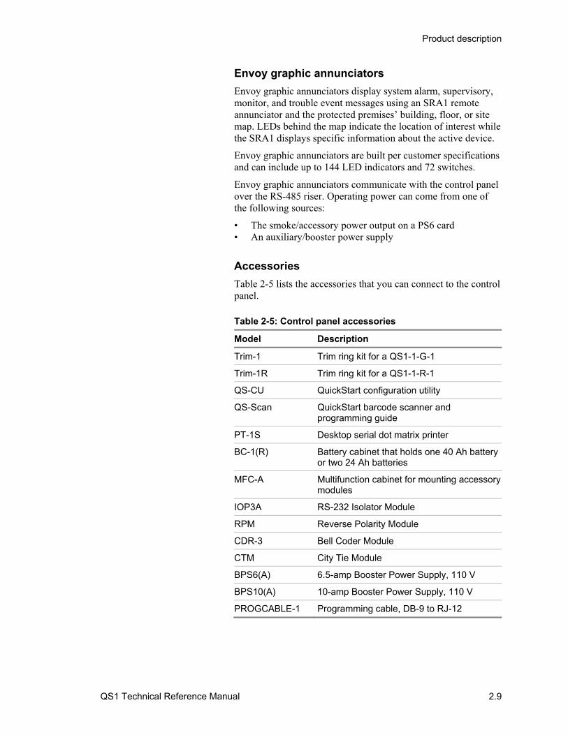
Accessories
Table 2-5 lists the accessories that you can connect to the control panel. Table 2-5: Control panel accessories
Model Description
Trim-1 Trim ring kit for a QS1-1-G-1
Trim-1R Trim ring kit for a QS1-1-R-1
QS-CU QuickStart configuration utility
QS-Scan QuickStart barcode scanner and programming guide
PT-1S Desktop serial dot matrix printer
BC-1(R) Battery cabinet that holds one 40 Ah battery or two 24 Ah batteries
MFC-A Multifunction cabinet for mounting accessory modules
IOP3A RS-232 Isolator Module
RPM Reverse Polarity Module
CDR-3 Bell Coder Module
CTM City Tie Module
BPS6(A) 6.5-amp Booster Power Supply, 110 V
BPS10(A) 10-amp Booster Power Supply, 110 V
PROGCABLE-1 Programming cable, DB-9 to RJ-12
Product description
2.10 QS1 Technical Reference Manual
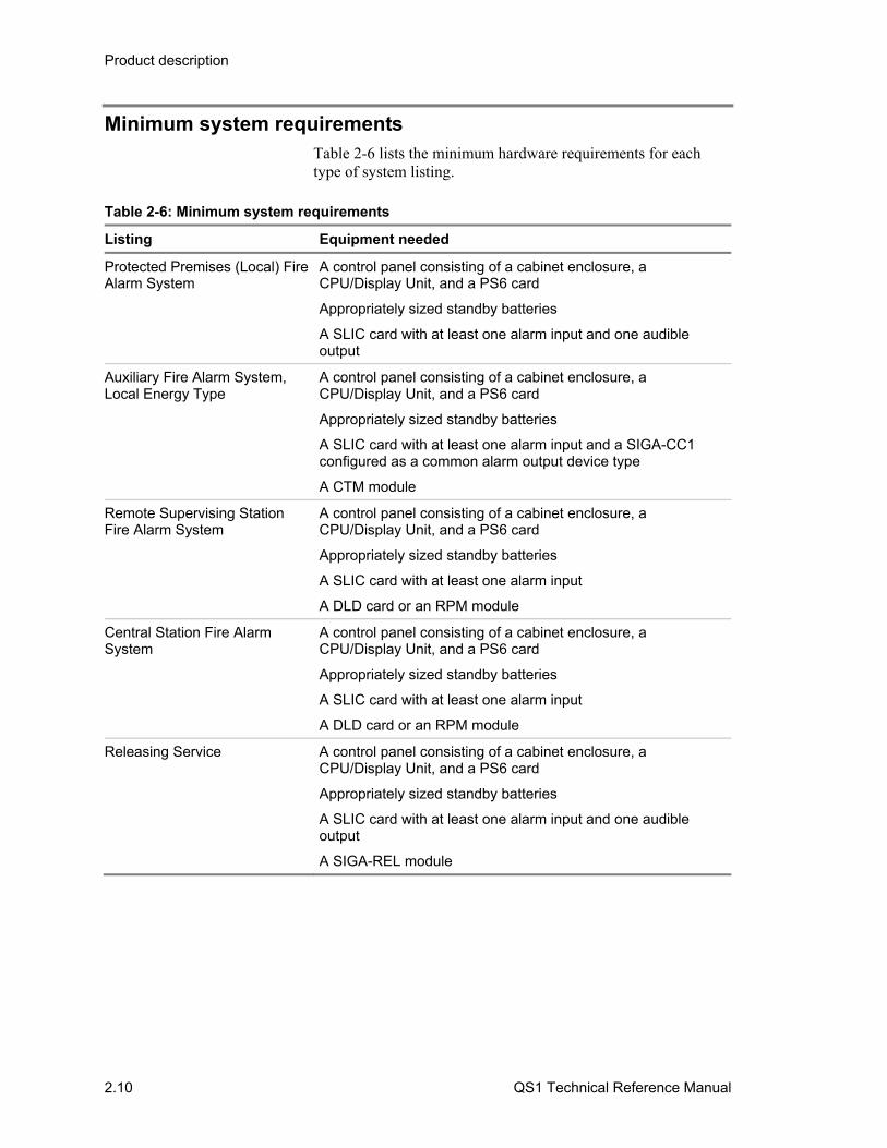
Minimum system requirements Table 2-6 lists the minimum hardware requirements for each type of system listing.
Table 2-6: Minimum system requirements
Listing Equipment needed
Protected Premises (Local) Fire Alarm System
A control panel consisting of a cabinet enclosure, a CPU/Display Unit, and a PS6 card
Appropriately sized standby batteries
A SLIC card with at least one alarm input and one audible output
Auxiliary Fire Alarm System, Local Energy Type
A control panel consisting of a cabinet enclosure, a CPU/Display Unit, and a PS6 card
Appropriately sized standby batteries
A SLIC card with at least one alarm input and a SIGA-CC1 configured as a common alarm output device type
A CTM module
Remote Supervising Station Fire Alarm System
A control panel consisting of a cabinet enclosure, a CPU/Display Unit, and a PS6 card
Appropriately sized standby batteries
A SLIC card with at least one alarm input
A DLD card or an RPM module
Central Station Fire Alarm System
A control panel consisting of a cabinet enclosure, a CPU/Display Unit, and a PS6 card
Appropriately sized standby batteries
A SLIC card with at least one alarm input
A DLD card or an RPM module
Releasing Service A control panel consisting of a cabinet enclosure, a CPU/Display Unit, and a PS6 card
Appropriately sized standby batteries
A SLIC card with at least one alarm input and one audible output
A SIGA-REL module

Product description
QS1 Technical Reference Manual 2.11
System status indicators
1 2 3 4 6 7 8 9 05
ALARM
Supervisory
CPU Fault
Ground Fault
Trouble
Disable/Test
Monitor
Power
PRESS ZONE FOR INFORMATION
Sys temR es et
AlarmSilenc e
H elp Status
Panel Silenced
Off
On
Enable Contro ls
M ENU D el Enter
Panel Silence/Acknowledge
D ril l
Optional controlsand indicators
1
78
65432
Table 2-7: System status indicator descriptions
No. Indicator Description
1 Alarm LED Flashing indicates new alarm event messages. On indicates alarm event messages have been acknowledged.
2 Supervisory LED Flashing indicates new supervisory event messages. On indicates supervisory event messages have been acknowledged.
3 Disable/Test LED On indicates a disable or test event message is present
Note: The disabled state has priority over the test state.
4 Monitor LED Flashing indicates new monitor event messages. On indicates monitor event messages have been acknowledged.
5 Trouble LED Flashing indicates new trouble event messages. On indicates trouble event messages have been acknowledged.
6 Ground Fault LED On indicates a ground fault
7 CPU Fault LED On indicates an unexpected restart or failure with the microprocessor
8 Power LED On indicates the control panel is energized

Product description
2.12 QS1 Technical Reference Manual
Operator controls and indicators
1 2 3 4 6 7 8 9 05
ALARM
Supervisory
CPU Fault
Ground Fault
Trouble
Disable/Test
Monitor
Power
PRESS ZONE FOR INFORMATION
SystemReset
AlarmSilence
Help Status
Panel Silenced
Off
On
Enable Controls
MENU Del Enter
Panel Silence/Acknowledge
Drill
Optional controlsand indicators
10
2
3
8
5, 6, 7
4
9
1
11 13, 14, 1512
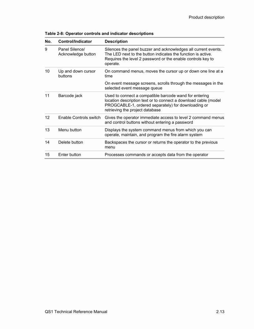
Table 2-8: Operator controls and indicator descriptions
No. Control/Indicator Description
1 Alphanumeric display Provides supplemental information relevant to the current functional condition of the control panel
2 Left and right cursor buttons
On command menus, moves the cursor left or right one character at a time in a data entry field
On event message screens, selects the previous or next event message queue
3 Help button Displays additional information about the selected event message
4 Status button Displays the Status menu from which you can identify system components that are active, disabled, or in the test state
5 System Reset button Restores the system to the normal state provided that no inputs are latched in the active state. The LED next to the button indicates the function is active. Requires the level 2 password or enable controls key to operate.
6 Alarm Silence button Turns off (silences) all active audible and common alarm output device types, and if configured, all visible device types. Pressing the button again turns them on. The LED next to the button indicates the function is active. Requires the level 2 password or the enable controls key to operate.
7 Drill button Turns on all audible and common alarm output device types, and if configured, all visible device types. Pressing the button again turns them off. The LED next to the button indicates the function is active. Requires the level 2 password to operate.
8 Numeric keypad Enters the number or selects the menu item shown on the button face
Product description
QS1 Technical Reference Manual 2.13
Table 2-8: Operator controls and indicator descriptions
No. Control/Indicator Description
9 Panel Silence/ Acknowledge button
Silences the panel buzzer and acknowledges all current events. The LED next to the button indicates the function is active. Requires the level 2 password or the enable controls key to operate.
10 Up and down cursor buttons
On command menus, moves the cursor up or down one line at a time
On event message screens, scrolls through the messages in the selected event message queue
11 Barcode jack Used to connect a compatible barcode wand for entering location description text or to connect a download cable (model PROGCABLE-1, ordered separately) for downloading or retrieving the project database
12 Enable Controls switch Gives the operator immediate access to level 2 command menus and control buttons without entering a password
13 Menu button Displays the system command menus from which you can operate, maintain, and program the fire alarm system
14 Delete button Backspaces the cursor or returns the operator to the previous menu
15 Enter button Processes commands or accepts data from the operator

Product description
2.14 QS1 Technical Reference Manual
Optional controls and indicators
1
2
3
4
5
6
7
8
9
10
11
12
13
14
15
16
17
18
19
20
21
22
23
24
25
26
27
28
29
30
1 2 3 4 6 7 8 9 05
ALARM
Supervisory
CPU Fault
Ground fault
Trouble
Disable/Test
Monitor
Power
PRESS ZONE FOR INFORMATION
SystemReset
AlarmSilence
Help Status
Panel Silenced
Off
On
Enable Controls
MENU Del Enter
Panel Silence/Acknowledge
Drill
1 2 3
Table 2-9: Optional control and indicator descriptions
No. Indicator Description
1 Zone display/select switch
Displays the location description, if programmed, for the corresponding zone. When enabling or disabling a zone, pressing the switch selects the corresponding zone in the zone list.
Note: This switch is not available on all LED/switch card models.
2 Active LED Red or yellow LED that indicates the corresponding zone is active (red = fire alarm zone, yellow = supervisory or monitor zone)
3 Trouble LED Yellow LED that indicates the corresponding zone is in a trouble state
Optional control and indicators are provided using LED/switch cards. Typically, LED/switch cards are used for zone annunciation but can be used for point annunciation or manual override controls as well. For more information, see the topic “LED/switch cards” in Chapter 3.
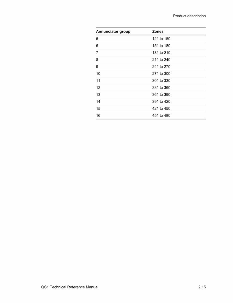
Zones are automatically mapped to LED/switch cards as shown in the table below. By default, the LED/switch card positioned closest to the alphanumeric display is assigned to Annunciator Group 1.
Annunciator group Zones
1 1 to 30
2 31 to 60
3 61 to 90
4 91 to 120
Product description
QS1 Technical Reference Manual 2.15
Annunciator group Zones
5 121 to 150
6 151 to 180
7 181 to 210
8 211 to 240
9 241 to 270
10 271 to 300
11 301 to 330
12 331 to 360
13 361 to 390
14 391 to 420
15 421 to 450
16 451 to 480

Product description
2.16 QS1 Technical Reference Manual
Alphanumeric display In addition to the system status indicators, the CPU/Display Unit uses an alphanumeric display to provide supplemental information related to the current functional condition of the control panel.
System Normal display screen
The alphanumeric display shows the System Normal display screen when the control panel is in the normal (quiescent) state.
05:45:00 06/21
System Normal
Your Building
Alarm History:0000
1
3
2
No Name Description
1 Time and date field
Displays the system time in 24-hour format and system date in MM/DD format, where:
• MM is the month’s number. Example: 06 is June.
• DD is the date
2 Banner window Displays “System Normal” and, if programmed, the facility name
3 Alarm history field
Displays how many times the control panel has entered the alarm state
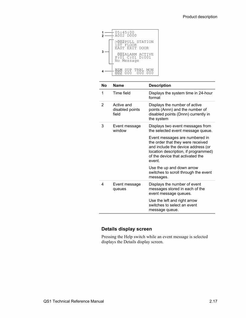
Event Message display screen
The alphanumeric display shows the Event Message display screen when the control panel enters the fire alarm, supervisory, monitor, trouble, disablement, or test state.
Product description
QS1 Technical Reference Manual 2.17
05:45:00A002 D000
>002PULL STATION1ST FLOOREAST EXIT DOOR
001ALARM ACTIVEP:01 C:01 D:001No Message
ALM SUP TRBL MON002 000 000 000
12
3
4
No Name Description
1 Time field Displays the system time in 24-hour format
2 Active and disabled points field
Displays the number of active points (Annn) and the number of disabled points (Dnnn) currently in the system
3 Event message window
Displays two event messages from the selected event message queue.
Event messages are numbered in the order that they were received and include the device address (or location description, if programmed) of the device that activated the event.
Use the up and down arrow switches to scroll through the event messages.
4 Event message queues
Displays the number of event messages stored in each of the event message queues.
Use the left and right arrow switches to select an event message queue.
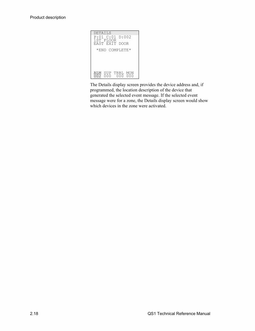
Details display screen
Pressing the Help switch while an event message is selected displays the Details display screen.
Product description
2.18 QS1 Technical Reference Manual
P:01 C:01 D:0021ST FLOOREAST EXIT DOOR
*END COMPLETE*
ALM SUP TRBL MON002 000 000 000
DETAILS
The Details display screen provides the device address and, if programmed, the location description of the device that generated the selected event message. If the selected event message were for a zone, the Details display screen would show which devices in the zone were activated.

Product description
QS1 Technical Reference Manual 2.19
Command menu organization Operator commands are organized into menus. There are four separate levels of command menus as described below.
Level 1 command menus
Table 2-10 lists the commands that you can always use. Entering a password is not required. Table 2-10: Level 1 command menus
Menu Commands
1) Status 1) All Active 2) Alarm 3) Supervisory 4) Trouble 5) Monitor 6) Test 7) Disabled Pts 8) Outputs 9) Internal
2) Reports 1) Maintenance 1) Dirty>80% 2) Dirty>20% 3) Single Device 4) Card Devices 2) Alarm History
3) Test 1) Lamp Test
4) Login
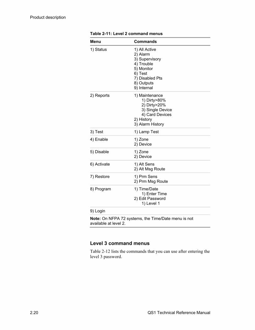
Level 2 command menus
Table 2-11 lists the commands that you can use after entering the level 2 password or after switching the Enable Controls key switch to the ON position.
Product description
2.20 QS1 Technical Reference Manual
Table 2-11: Level 2 command menus
Menu Commands
1) Status 1) All Active 2) Alarm 3) Supervisory 4) Trouble 5) Monitor 6) Test 7) Disabled Pts 8) Outputs 9) Internal
2) Reports 1) Maintenance 1) Dirty>80% 2) Dirty>20% 3) Single Device 4) Card Devices 2) History 3) Alarm History
3) Test 1) Lamp Test
4) Enable 1) Zone 2) Device
5) Disable 1) Zone 2) Device
6) Activate 1) Alt Sens 2) Alt Msg Route
7) Restore 1) Prm Sens 2) Prm Msg Route
8) Program 1) Time/Date 1) Enter Time 2) Edit Password 1) Level 1
9) Login
Note: On NFPA 72 systems, the Time/Date menu is not available at level 2.
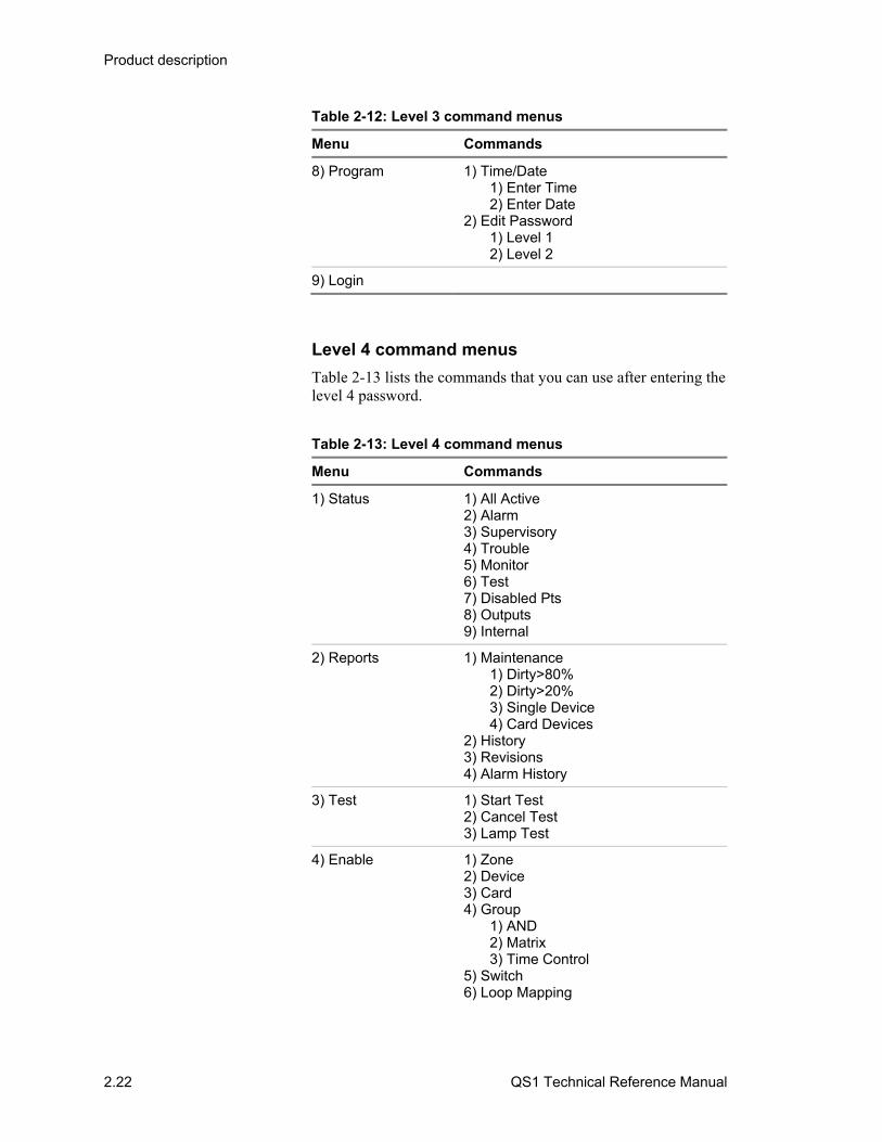
Level 3 command menus
Table 2-12 lists the commands that you can use after entering the level 3 password.

Product description
QS1 Technical Reference Manual 2.21
Table 2-12: Level 3 command menus
Menu Commands
1) Status 1) All Active 2) Alarm 3) Supervisory 4) Trouble 5) Monitor 6) Test 7) Disabled Pts 8) Outputs 9) Internal
2) Reports 1) Maintenance 1) Dirty>80% 2) Dirty>20% 3) Single Device 4) Card Devices 2) History 3) Revisions 4) Alarm History
3) Test 1) Start Test 2) Cancel Test 3) Lamp Test
4) Enable 1) Zone 2) Device 3) Group 1) AND 2) Matrix 3) Time Control 4) Switch 5) Loop Mapping
5) Disable 1) Zone 2) Device 3) Group 1) AND 2) Matrix 3) Time Control 4) Switch 5) Loop Mapping
6) Activate 1) Output 2) Alt Sens 3) Alt Msg Route 4) LED
7) Restore 1) Output 2) Prm Sens 3) Prm Msg Route 4) LED
Product description
2.22 QS1 Technical Reference Manual
Table 2-12: Level 3 command menus
Menu Commands
8) Program 1) Time/Date 1) Enter Time 2) Enter Date 2) Edit Password 1) Level 1 2) Level 2
9) Login
Level 4 command menus
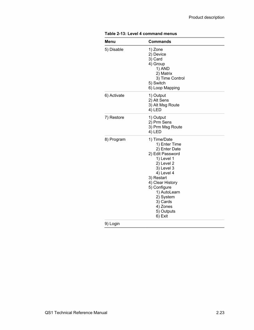
Table 2-13 lists the commands that you can use after entering the level 4 password.
Table 2-13: Level 4 command menus
Menu Commands
1) Status 1) All Active 2) Alarm 3) Supervisory 4) Trouble 5) Monitor 6) Test 7) Disabled Pts 8) Outputs 9) Internal
2) Reports 1) Maintenance 1) Dirty>80% 2) Dirty>20% 3) Single Device 4) Card Devices 2) History 3) Revisions 4) Alarm History
3) Test 1) Start Test 2) Cancel Test 3) Lamp Test
4) Enable 1) Zone 2) Device 3) Card 4) Group 1) AND 2) Matrix 3) Time Control 5) Switch 6) Loop Mapping
Product description
QS1 Technical Reference Manual 2.23
Table 2-13: Level 4 command menus
Menu Commands
5) Disable 1) Zone 2) Device 3) Card 4) Group 1) AND 2) Matrix 3) Time Control 5) Switch 6) Loop Mapping
6) Activate 1) Output 2) Alt Sens 3) Alt Msg Route 4) LED
7) Restore 1) Output 2) Prm Sens 3) Prm Msg Route 4) LED
8) Program 1) Time/Date 1) Enter Time 2) Enter Date 2) Edit Password 1) Level 1 2) Level 2 3) Level 3 4) Level 4 3) Restart 4) Clear History 5) Configure 1) AutoLearn 2) System 3) Cards 4) Zones 5) Outputs 6) Exit
9) Login
Product description
2.24 QS1 Technical Reference Manual
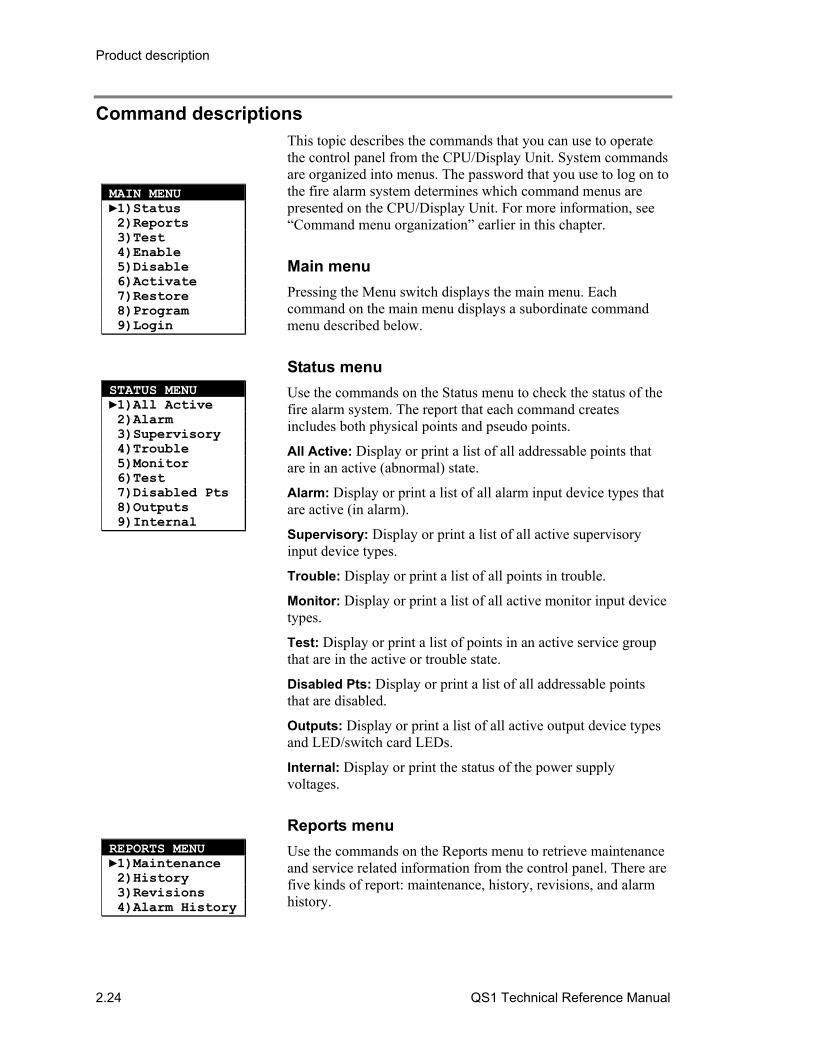
Command descriptions This topic describes the commands that you can use to operate the control panel from the CPU/Display Unit. System commands are organized into menus. The password that you use to log on to the fire alarm system determines which command menus are presented on the CPU/Display Unit. For more information, see “Command menu organization” earlier in this chapter.
Main menu
Pressing the Menu switch displays the main menu. Each command on the main menu displays a subordinate command menu described below.
Status menu
Use the commands on the Status menu to check the status of the fire alarm system. The report that each command creates includes both physical points and pseudo points.
All Active: Display or print a list of all addressable points that are in an active (abnormal) state.
Alarm: Display or print a list of all alarm input device types that are active (in alarm).
Supervisory: Display or print a list of all active supervisory input device types.
Trouble: Display or print a list of all points in trouble.
Monitor: Display or print a list of all active monitor input device types.
Test: Display or print a list of points in an active service group that are in the active or trouble state.
Disabled Pts: Display or print a list of all addressable points that are disabled.
Outputs: Display or print a list of all active output device types and LED/switch card LEDs.
Internal: Display or print the status of the power supply voltages.
Reports menu
Use the commands on the Reports menu to retrieve maintenance and service related information from the control panel. There are five kinds of report: maintenance, history, revisions, and alarm history.
STATUS MENU 1)All Active 2)Alarm 3)Supervisory 4)Trouble 5)Monitor 6)Test 7)Disabled Pts 8)Outputs 9)Internal
REPORTS MENU 1)Maintenance 2)History 3)Revisions 4)Alarm History
MAIN MENU 1)Status 2)Reports 3)Test 4)Enable 5)Disable 6)Activate 7)Restore 8)Program 9)Login

Product description
QS1 Technical Reference Manual 2.25
Maintenance
The Maintenance command lets you select one of the reports described below.
Dirty > 80%: Creates a report that lists all intelligent addressable smoke detectors that are more than 80% dirty. A smoke detector that is more than 80% dirty should be cleaned or replaced as soon as possible.
Dirty > 20%: Creates a report that lists all intelligent addressable smoke detectors that are more than 20% dirty. A smoke detector that is more than 20% dirty should be noted for possible cleaning or replacing in the future.
Single Device: Creates a report that lists the attributes of a specific intelligent addressable smoke detector. The attributes listed include type, location description (if programmed), percent dirty, and primary and alternate alarm sensitivity values. Requires the panel-card-device address (PPCCDDD) of the detector.
Card Devices: Creates a report that lists the attributes of every intelligent addressable smoke detector connected to a specific loop controller. The attributes listed include type, location description (if programmed), percent dirty, and primary and alternate alarm sensitivity values. Requires the panel-card address (PPCC) of the loop controller.
History
The History command creates a report that lists the last 1,000 events or operator instructions processed by the control panel. The items in the list are presented in reverse chronological order and contain the following information:
• The event or system command name • The time and date of occurrence • The source that initiated the event or command
Revisions
The Revisions command creates a report that lists the revision level of all the hardware and software components installed in the cabinet.
For the project database, the report includes:
• The market place • The configuration utility version number and project number
if the database loaded into the panel was created using the configuration utility
• The CPU firmware revision number • The database serial number and the date it was compiled
For the CPU/Display Unit, the report includes:
Product description
2.26 QS1 Technical Reference Manual
• The CPU type and firmware version number • The quantity and type of LED/switch cards installed
For each option card, the report includes:
• The card number • The card type • The firmware revision number and date
Alarm History
The Alarm History command creates a report that lists the number of times the control panel has entered the alarm state.
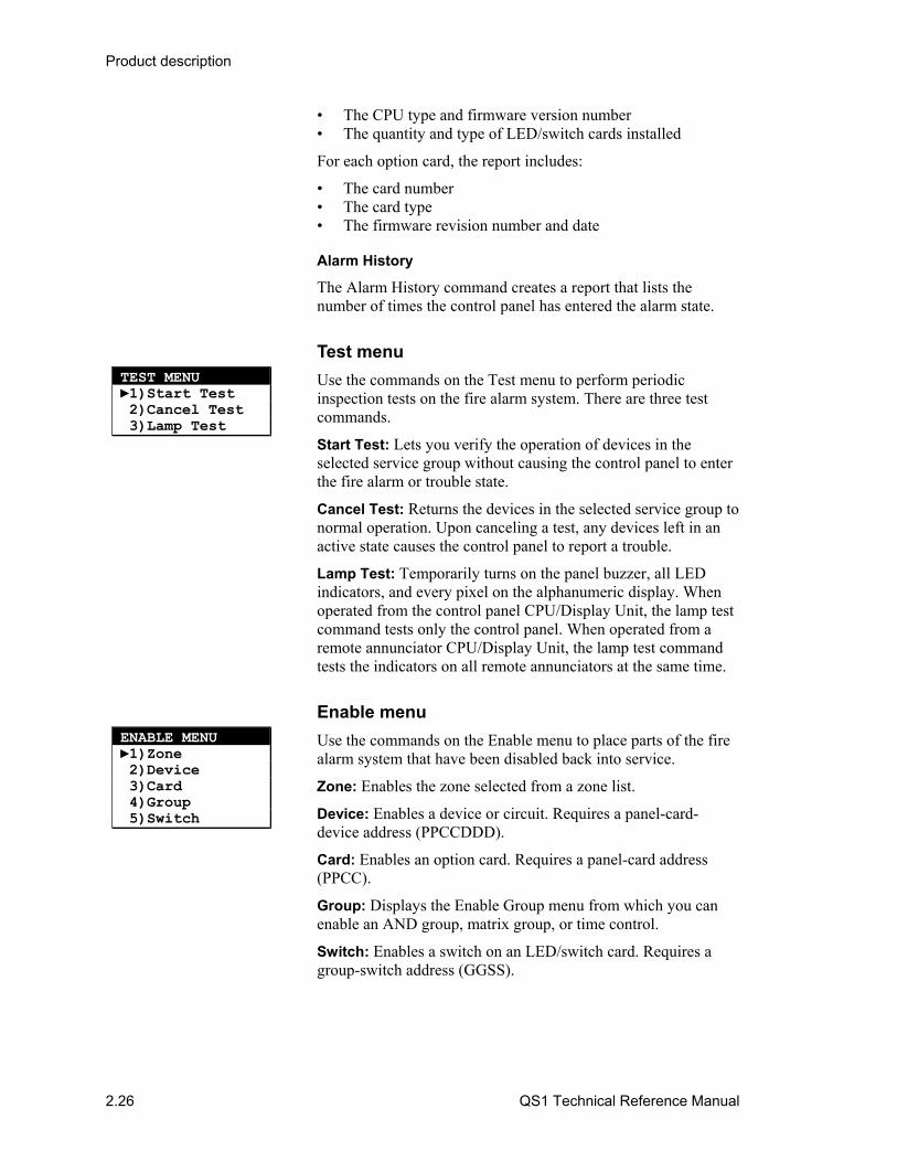
Test menu
Use the commands on the Test menu to perform periodic inspection tests on the fire alarm system. There are three test commands.
Start Test: Lets you verify the operation of devices in the selected service group without causing the control panel to enter the fire alarm or trouble state.
Cancel Test: Returns the devices in the selected service group to normal operation. Upon canceling a test, any devices left in an active state causes the control panel to report a trouble.
Lamp Test: Temporarily turns on the panel buzzer, all LED indicators, and every pixel on the alphanumeric display. When operated from the control panel CPU/Display Unit, the lamp test command tests only the control panel. When operated from a remote annunciator CPU/Display Unit, the lamp test command tests the indicators on all remote annunciators at the same time.
Enable menu
Use the commands on the Enable menu to place parts of the fire alarm system that have been disabled back into service.
Zone: Enables the zone selected from a zone list.
Device: Enables a device or circuit. Requires a panel-card-device address (PPCCDDD).
Card: Enables an option card. Requires a panel-card address (PPCC).
Group: Displays the Enable Group menu from which you can enable an AND group, matrix group, or time control.
Switch: Enables a switch on an LED/switch card. Requires a group-switch address (GGSS).
TEST MENU 1)Start Test 2)Cancel Test 3)Lamp Test
ENABLE MENU 1)Zone 2)Device 3)Card 4)Group 5)Switch
Product description
QS1 Technical Reference Manual 2.27
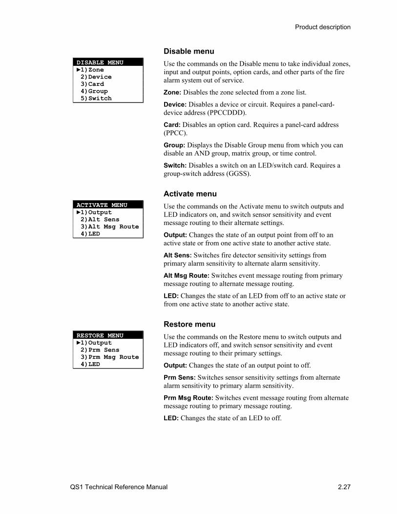
Disable menu
Use the commands on the Disable menu to take individual zones, input and output points, option cards, and other parts of the fire alarm system out of service.
Zone: Disables the zone selected from a zone list.
Device: Disables a device or circuit. Requires a panel-card-device address (PPCCDDD).
Card: Disables an option card. Requires a panel-card address (PPCC).
Group: Displays the Disable Group menu from which you can disable an AND group, matrix group, or time control.
Switch: Disables a switch on an LED/switch card. Requires a group-switch address (GGSS).
Activate menu
Use the commands on the Activate menu to switch outputs and LED indicators on, and switch sensor sensitivity and event message routing to their alternate settings.
Output: Changes the state of an output point from off to an active state or from one active state to another active state.
Alt Sens: Switches fire detector sensitivity settings from primary alarm sensitivity to alternate alarm sensitivity.
Alt Msg Route: Switches event message routing from primary message routing to alternate message routing.
LED: Changes the state of an LED from off to an active state or from one active state to another active state.
Restore menu
Use the commands on the Restore menu to switch outputs and LED indicators off, and switch sensor sensitivity and event message routing to their primary settings.
Output: Changes the state of an output point to off.
Prm Sens: Switches sensor sensitivity settings from alternate alarm sensitivity to primary alarm sensitivity.
Prm Msg Route: Switches event message routing from alternate message routing to primary message routing.
LED: Changes the state of an LED to off.
DISABLE MENU 1)Zone 2)Device 3)Card 4)Group 5)Switch
ACTIVATE MENU 1)Output 2)Alt Sens 3)Alt Msg Route 4)LED
RESTORE MENU 1)Output 2)Prm Sens 3)Prm Msg Route 4)LED
Product description
2.28 QS1 Technical Reference Manual
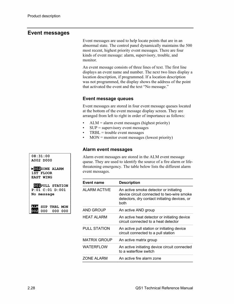
Event messages Event messages are used to help locate points that are in an abnormal state. The control panel dynamically maintains the 500 most recent, highest priority event messages. There are four kinds of event message: alarm, supervisory, trouble, and monitor.
An event message consists of three lines of text. The first line displays an event name and number. The next two lines display a location description, if programmed. If a location description was not programmed, the display shows the address of the point that activated the event and the text “No message.”
Event message queues
Event messages are stored in four event message queues located at the bottom of the event message display screen. They are arranged from left to right in order of importance as follows:
• ALM = alarm event messages (highest priority) • SUP = supervisory event messages • TRBL = trouble event messages • MON = monitor event messages (lowest priority)
Alarm event messages
Alarm event messages are stored in the ALM event message queue. They are used to identify the source of a fire alarm or life-threatening emergency. The table below lists the different alarm event messages.
Event name Description
ALARM ACTIVE An active smoke detector or initiating device circuit connected to two-wire smoke detectors, dry contact initiating devices, or both
AND GROUP An active AND group
HEAT ALARM An active heat detector or initiating device circuit connected to a heat detector
PULL STATION An active pull station or initiating device circuit connected to a pull station
MATRIX GROUP An active matrix group
WATERFLOW An active initiating device circuit connected to a waterflow switch
ZONE ALARM An active fire alarm zone
08:31:00 A002 D000 002ZONE ALARM 1ST FLOOR EAST WING 001PULL STATION P:01 C:01 D:001 No message ALM SUP TRBL MON 002 000 000 000
Product description
QS1 Technical Reference Manual 2.29
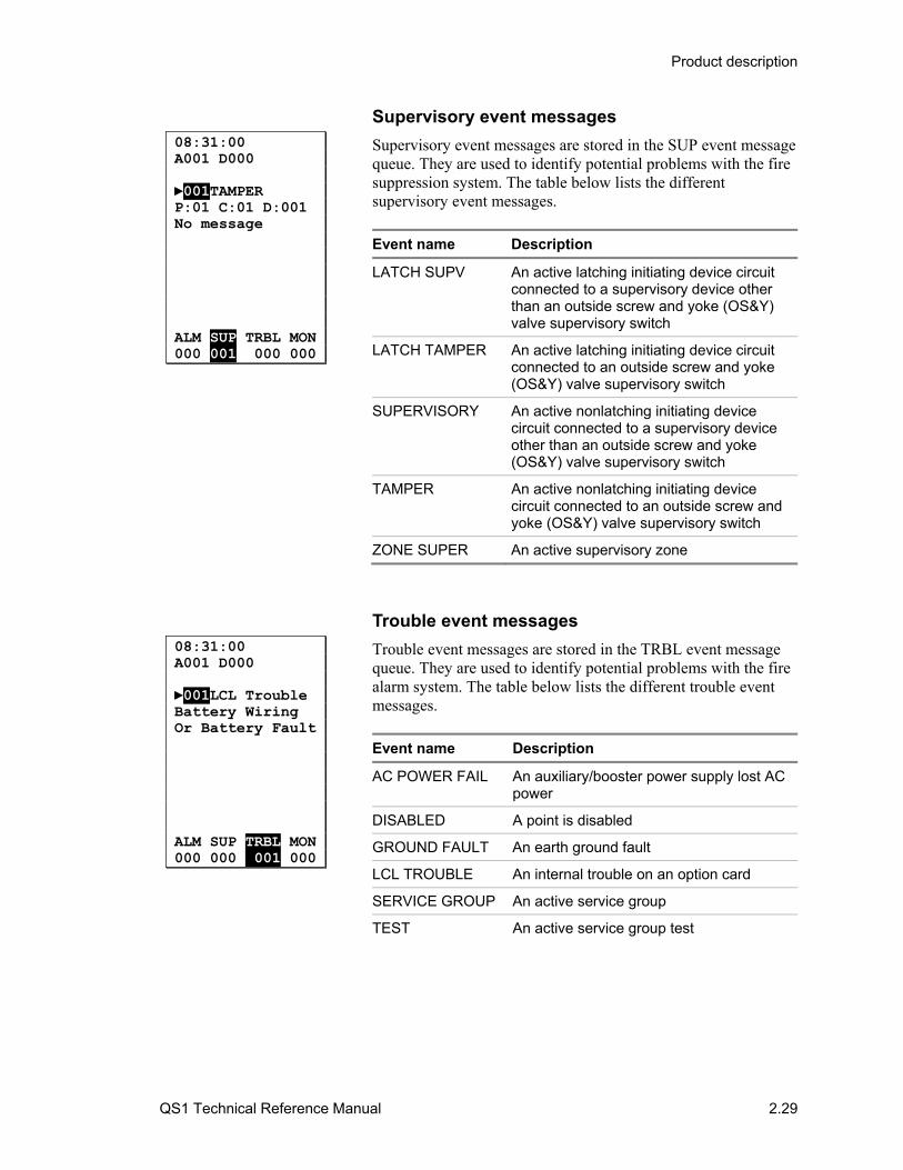
Supervisory event messages
Supervisory event messages are stored in the SUP event message queue. They are used to identify potential problems with the fire suppression system. The table below lists the different supervisory event messages.
Event name Description
LATCH SUPV An active latching initiating device circuit connected to a supervisory device other than an outside screw and yoke (OS&Y) valve supervisory switch
LATCH TAMPER An active latching initiating device circuit connected to an outside screw and yoke (OS&Y) valve supervisory switch
SUPERVISORY An active nonlatching initiating device circuit connected to a supervisory device other than an outside screw and yoke (OS&Y) valve supervisory switch
TAMPER An active nonlatching initiating device circuit connected to an outside screw and yoke (OS&Y) valve supervisory switch
ZONE SUPER An active supervisory zone
Trouble event messages
Trouble event messages are stored in the TRBL event message queue. They are used to identify potential problems with the fire alarm system. The table below lists the different trouble event messages.
Event name Description
AC POWER FAIL An auxiliary/booster power supply lost AC power
DISABLED A point is disabled
GROUND FAULT An earth ground fault
LCL TROUBLE An internal trouble on an option card
SERVICE GROUP An active service group
TEST An active service group test
08:31:00 A001 D000 001LCL Trouble Battery Wiring Or Battery Fault ALM SUP TRBL MON 000 000 001 000
08:31:00 A001 D000 001TAMPER P:01 C:01 D:001 No message ALM SUP TRBL MON 000 001 000 000
Product description
2.30 QS1 Technical Reference Manual
Event name Description
TROUBLE A common trouble event message for the following Signature troubles:
• BAD PERSONATY: Personality mismatch
• BAD TYPE: Device type mismatch
• COMM FAULT: Communication failure
• DEV COMPATIB: Incompatible device
• DIRTY HEAD: Detector is 100% dirty and needs to be cleaned or replaced
• INTERNAL TBL: Internal trouble
TROUBLE OPEN An open detected on an initiating device circuit or on a notification appliance circuit
TROUBLE SHORT A short detected on a notification appliance circuit
UNEXPECT DEV A device is installed but not defined in the project database
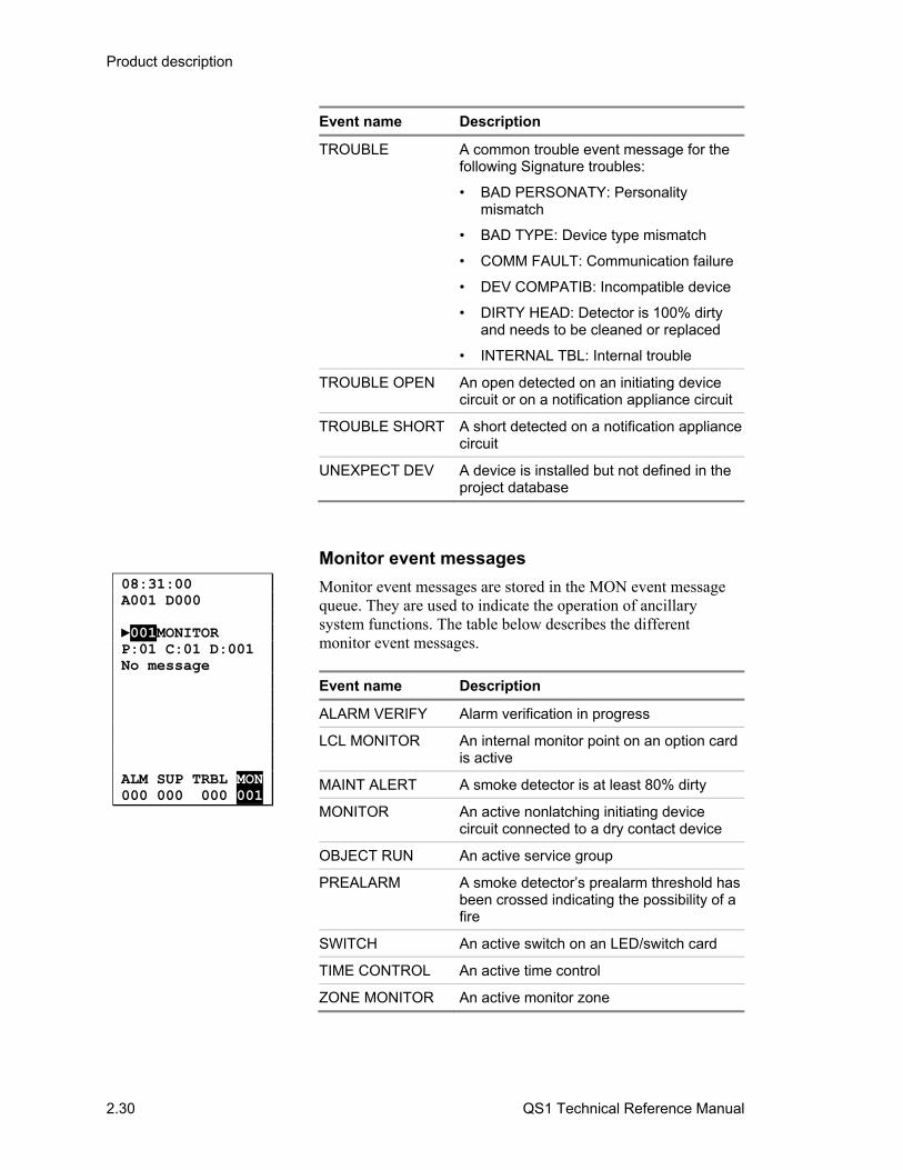
Monitor event messages
Monitor event messages are stored in the MON event message queue. They are used to indicate the operation of ancillary system functions. The table below describes the different monitor event messages.
Event name Description
ALARM VERIFY Alarm verification in progress
LCL MONITOR An internal monitor point on an option card is active
MAINT ALERT A smoke detector is at least 80% dirty
MONITOR An active nonlatching initiating device circuit connected to a dry contact device
OBJECT RUN An active service group
PREALARM A smoke detector’s prealarm threshold has been crossed indicating the possibility of a fire
SWITCH An active switch on an LED/switch card
TIME CONTROL An active time control
ZONE MONITOR An active monitor zone
08:31:00 A001 D000 001MONITOR P:01 C:01 D:001 No message ALM SUP TRBL MON 000 000 000 001
Product description
QS1 Technical Reference Manual 2.31
Control panel operation The control panel can operate in the following states:
• Normal • Alarm • Supervisory • Trouble • Monitor • Disable • Test
Each state is described in detail below.
Note: For the control panel to indicate an abnormal operating state, the event message for the activated point must be routed to the control panel. Event message routing does not affect the outputs of the abnormal state.
Normal state
The control panel operates in the normal state in the absence of any events. In the normal state, only the power LED is on and the alphanumeric display shows the System Normal display screen.
Alarm state
The control panel enters the alarm state when a point signals an alarm event.
Output of the alarm state
Upon entering the alarm state, the control panel:
• Changes the contact positions on the common alarm relay (Relay 1 on the PS6 card)
• Activates all common alarm outputs
• Executes the active response for the First Alarm pseudo point
• Executes the active response for the point that signaled the alarm event
Indication of the alarm state
To indicate it is in the alarm state, the control panel:
• Sounds the panel buzzer using a repeating pattern of four beeps
• Flashes the Alarm LED at a rate of 300 times per minute

Product description
2.32 QS1 Technical Reference Manual
• Displays an event message in the ALM message queue for the point that signaled the alarm event
If the active point is an alarm zone and an LED/switch card is installed, the control panel also flashes the zone’s alarm LED at a rate of 300 times per minute.
Supervisory state
The control panel enters the supervisory state when a point signals a supervisory event.
Output of the supervisory state
Upon entering the supervisory state, the control panel:
• Closes the normally open contacts on the common supervisory relay (Relay 2 on the PS6 card)
• Executes the active response for the First Supervisory pseudo point
• Executes the active response for the point that signaled the supervisory event
Indication of the supervisory state
To indicate it is in the supervisory state, the control panel:
• Sounds the panel buzzer using a repeating pattern of two beeps
• Flashes the Supervisory LED at a rate of 30 times per minute
• Displays an event message in the SUP message queue for the point that signaled the supervisory event
If the active point is a supervisory zone and an LED/switch card is installed, the control panel also flashes the zone’s active LED at a rate of 300 times per minute.
Trouble state
The control panel enters the trouble state when a point signals a trouble event.
Output of the trouble state
Upon entering the trouble state, the control panel:
• Opens the normally closed contacts on the common trouble relay (Relay 3 on the PS6 card)
• Executes the trouble response for the First Trouble pseudo point

Product description
QS1 Technical Reference Manual 2.33
• Executes the trouble response for the point that signaled the trouble event
Indication of the trouble state
To indicate it is in the trouble state, the control panel:
• Sounds the panel buzzer at a rate of 30 times per minute
• Flashes the Trouble LED at a rate of 30 times per minute
• Displays an event message in the TRBL message queue for the point that signaled the trouble event
• Turns on the CPU Fault LED if the trouble is a CPU fault
• Turns on the Ground Fault LED if the trouble is an earth ground fault
If the point is an alarm, supervisory, or monitor zone and an LED/switch card is installed, the control panel also flashes the zone’s trouble LED at a rate of 300 times per minute.
Note: Trouble indications are restored automatically when the trouble condition is cleared. If the panel buzzer has been silenced, a new trouble re-sounds the buzzer.
Monitor state
The control panel enters the monitor state when a point signals a monitor event.
Output of the monitor state
Upon entering the monitor state, the control panel:
• Executes the active response for the First Monitor pseudo point
• Executes the active response for the point that signaled the monitor event
Indication of the monitor state
To indicate it is in the monitor state, the control panel:
• Sounds the panel buzzer using a repeating pattern of four beeps
• Flashes the Monitor LED at a rate of 30 times per minute
• Displays the point’s event message in the MON message queue
If the point is a monitor zone and an LED/switch card is installed, the control panel also flashes the zone’s active LED at a rate of 300 times per minute.

Product description
2.34 QS1 Technical Reference Manual
Note: Monitor indications are restored automatically when the monitor input is restored.
Disable state
The control panel enters the disable state when a point signals a disable event.
Note: For anything other than a zone, use the Disabled Pts. command on the Status menu to identify a disabled point. For more information, see “Checking system status” in Chapter 5.
Output of the disable state
Upon entering the disable state, the control panel:
• Opens the normally closed contacts on the common trouble relay (Relay 3 on the PS6 card)
• Executes the trouble response for the First Trouble pseudo point
• Executes the trouble response for the First Disable pseudo point
• Executes the disablement response for the point that signaled the disable event
Indication of the disable state
To indicate it is in the disable state, the control panel:
• Sounds the panel buzzer at a rate of 30 times per minute
• Turns on the Disable/Test LED
• Flashes the Trouble LED at a rate of 30 times per minute
• Displays an event message in the TRBL message queue for the First Trouble pseudo point
• Displays an event message in the TRBL message queue for the point that signaled the disable event. This is the first line of the message: DISABLED.
When a point is disabled, the control panel does not process any of the point’s status changes and the point remains in its current state. For example, if an audible device type in the normal state were disabled and subsequently activated, the audible device type would not turn on until it was enabled. Conversely, if an active audible device type were disabled and subsequently restored, the audible device type would not turn off until it was enabled.
If a point in trouble is disabled and the cause of the trouble changes while the point is disabled, the point’s original trouble event message may not update when the point is enabled. For example, a shorted notification appliance circuit whose wiring is

Product description
QS1 Technical Reference Manual 2.35
opened after it has been disabled still displays this event message after it is enabled: TROUBLE SHRT.
Test state
The control panel enters the test state when a service group is activated.
Output of the test state
Upon entering the test state, the control panel:
• Executes the active response for the First Monitor pseudo point
• Executes the trouble response for the First Trouble pseudo point
• Executes the trouble response for the First Test pseudo point
• Executes the running response for the service group that was activated
While in the test state:
• When a member of an active service group signals an active event, the control panel executes the service group’s active test response
• When a member of an active service group signals a trouble event, the control panel executes the service group’s trouble test response
Note: If you do not program a trouble test response, the control panel executes the active test response instead.
Indication of the test state
To indicate it is in the test state, the control panel:
• Sounds the panel buzzer at a rate of 30 times per minute
• Turns on the Disable/Test LED
• Flashes the Monitor LED at a rate of 30 times per minute
• Flashes the Trouble LED at a rate of 30 times per minute
• Displays an event message in the TRBL message queue for the First Test pseudo point
• Displays an event message in the MON message queue for the service group that was activated. This is the first line of the message: OBJECT RUN.

Product description
2.36 QS1 Technical Reference Manual

QS1 Technical Reference Manual 3.1
Chapter 3 Panel components
Summary
This chapter provides technical descriptions of the components that can be installed in the control panel.
Content
PS6 Power Supply Card • 3.3 Description • 3.3 Specifications • 3.4 Relay outputs • 3.5 Smoke/accessory power output • 3.6 RS-485 port • 3.6 RS-232 port • 3.7 Auxiliary power outputs • 3.8 Standby batteries • 3.8 Address switch settings • 3.9 Jumper settings • 3.9
SLIC Signature Loop Interface Controller • 3.11 Description • 3.11 Specifications • 3.11 Notification appliance circuits • 3.12 Intelligent addressable loop • 3.14 Address switch settings • 3.15 Jumper settings • 3.15 Two-wire smoke detector application • 3.16
ZR8 Relay Card • 3.19 Description • 3.19 Specifications • 3.19 Relay outputs • 3.20 Address switch settings • 3.20 Jumper settings • 3.21
DLD Dual Line Dialer Card • 3.22 Description • 3.22 Specifications • 3.22 Address switch settings • 3.22 AutoCID feature • 3.23 Wiring • 3.25
NT-A (RS-485 card with QS-232 module) • 3.27 Description • 3.27 Specifications • 3.27 Address switch settings • 3.28 Jumper settings • 3.28 Wiring • 3.29
LED/switch cards • 3.30 SL30 card • 3.30 SL30-1 card • 3.31

Panel components
3.2 QS1 Technical Reference Manual
SL30L card • 3.31 SL20L5S • 3.32
Panel components
QS1 Technical Reference Manual 3.3
PS6 Power Supply Card
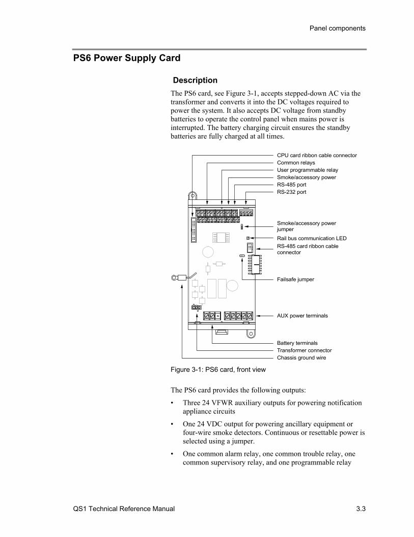
Description
The PS6 card, see Figure 3-1, accepts stepped-down AC via the transformer and converts it into the DC voltages required to power the system. It also accepts DC voltage from standby batteries to operate the control panel when mains power is interrupted. The battery charging circuit ensures the standby batteries are fully charged at all times.
RS-232 portRS-485 portSmoke/accessory powerUser programmable relayCommon relaysCPU card ribbon cable connector
Smoke/accessory powerjumper
Rail bus communication LED
RS-485 card ribbon cableconnector
Failsafe jumper
AUX power terminals
Battery terminals Transformer connector Chassis ground wire
Figure 3-1: PS6 card, front view
The PS6 card provides the following outputs:
• Three 24 VFWR auxiliary outputs for powering notification appliance circuits
• One 24 VDC output for powering ancillary equipment or four-wire smoke detectors. Continuous or resettable power is selected using a jumper.
• One common alarm relay, one common trouble relay, one common supervisory relay, and one programmable relay
Panel components
3.4 QS1 Technical Reference Manual
Specifications Footprint: Double space Wire size: 18 to 12 AWG (0.75 to 2.5 sq. mm) Input voltage
AC input: 115/230 V, 50/60 Hz via transformer DC input: 24 VDC via batteries
Battery charging circuit Charge voltage: 24 VDC Deep discharge voltage: 19 VDC Charge current: 2 A Charge capacity: 40 Ah (UL), 30 Ah (ULC) Battery type: Sealed lead acid Standby time: 24 hours
Maximum rail load: 1.32 A at 24 VDC Smoke/accessory power output circuit
UL rating: Special application Voltage: 19.5 to 26.3 VDC Current: 250 mA Continuous or resettable via jumper selection
Auxiliary power output circuits Quantity: 3 UL rating: Special application Voltage: 17.5 to 26.4 VFWR (full-wave rectified) Current: 1.5 A each circuit, 4.5 A total
RS-485 port Wire type: Twisted pair, 6 twists/ft. (20 twists/m), min. Circuit capacitance: 0.4 μF. max. Circuit resistance: 100 Ω, max. Circuit length: 3,000 ft. (914.4 m), max.
RS-232 port Circuit length: 20 ft. (6.1 m), max.
Relay 1 (common alarm relay) Type: Form C Contact rating: 1 A at 20.0 to 26.4 VDC (0.6 PF)
Relay 2 (common supervisory relay) Type: Normally open Contact rating: 1 A at 20.0 to 26.4 VDC (0.6 PF)
Relay 3 (common trouble relay) Type: Normally open, held closed Contact rating: 1 A at 20.0 to 26.4 VDC (0.6 PF)
Relay 4 (programmable relay) Type: Normally open Contact rating: 1 A at 20.0 to 26.4 VDC (0.6 PF)
Ground fault impedance: 10 kΩ Operating voltage: 24 VDC Current requirements
Standby current: 125 mA Alarm current: 132 mA
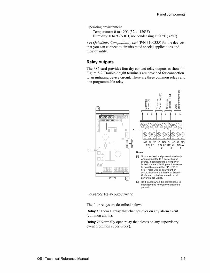
Panel components
QS1 Technical Reference Manual 3.5
Operating environment Temperature: 0 to 49C (32 to 120F) Humidity: 0 to 93% RH, noncondensing at 90°F (32°C)
See QuickStart Compatibility List (P/N 3100335) for the devices that you can connect to circuits rated special applications and their quantity.
Relay outputs
The PS6 card provides four dry contact relay outputs as shown in Figure 3-2. Double-height terminals are provided for connection to an initiating device circuit. There are three common relays and one programmable relay.
RELAY1
RELAY2
RELAY3
RELAY4
Com
mon
Ala
rm [1
]
Com
mon
Sup
ervi
sory
[1]
Com
mon
Trou
ble
[1] [
2]
Use
rpr
ogra
mm
able
[1]
NO NCC C NO C NO C NO
Notes
[1] Not supervised and power-limited only when connected to a power-limited source. I
[2] Held closed when the control panel is energized and no trouble signals are present.
f connected to a nonpower-limited source, all wiring on double-row terminal block must be FPL, FPLP, FPLR rated wire or equivalent, in accordance with the
and routed separate from all power-limited wiring.
National Electric Code,
Figure 3-2: Relay output wiring
The four relays are described below.
Relay 1: Form C relay that changes over on any alarm event (common alarm).
Relay 2: Normally open relay that closes on any supervisory event (common supervisory).
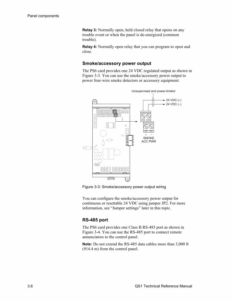
Panel components
3.6 QS1 Technical Reference Manual
Relay 3: Normally open, held closed relay that opens on any trouble event or when the panel is de-energized (common trouble).
Relay 4: Normally open relay that you can program to open and close.
Smoke/accessory power output
The PS6 card provides one 24 VDC regulated output as shown in Figure 3-3. You can use the smoke/accessory power output to power four-wire smoke detectors or accessory equipment.
SMOKEACC PWR
24 VDC ( )24 VDC ( )
Unsupervised and power-limited
Figure 3-3: Smoke/accessory power output wiring
You can configure the smoke/accessory power output for continuous or resettable 24 VDC using jumper JP2. For more information, see “Jumper settings” later in this topic.
RS-485 port
The PS6 card provides one Class B RS-485 port as shown in Figure 3-4. You can use the RS-485 port to connect remote annunciators to the control panel.
Note: Do not extend the RS-485 data cables more than 3,000 ft (914.4 m) from the control panel.
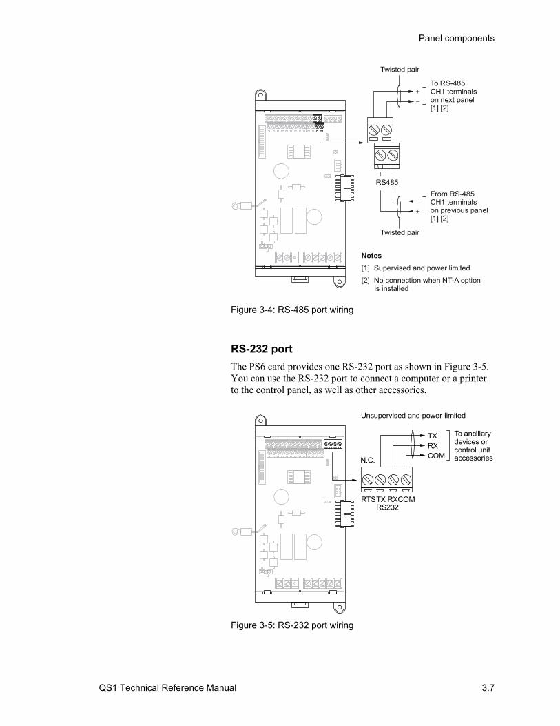
Panel components
QS1 Technical Reference Manual 3.7
RS485
Twisted pair
To RS-485CH1 terminalson next panel [1] [2]
Twisted pair
Notes
[1] Supervised and power limited
[2] No connection when NT-A option is installed
From RS-485CH1 terminalson previous panel [1] [2]
Figure 3-4: RS-485 port wiring
RS-232 port
The PS6 card provides one RS-232 port as shown in Figure 3-5. You can use the RS-232 port to connect a computer or a printer to the control panel, as well as other accessories.
Unsupervised and power-limited
To ancillarydevices or control unitaccessories
RTSTX RXCOMRS232
N.C.
TXRXCOM
Figure 3-5: RS-232 port wiring
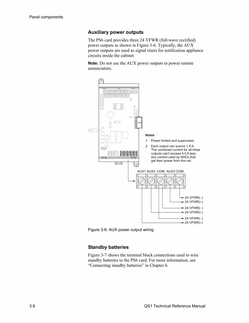
Panel components
3.8 QS1 Technical Reference Manual
Auxiliary power outputs
The PS6 card provides three 24 VFWR (full-wave rectified) power outputs as shown in Figure 3-6. Typically, the AUX power outputs are used as signal risers for notification appliance circuits inside the cabinet.
Note: Do not use the AUX power outputs to power remote annunciators.
AUX1 AUX2 COM AUX3 COM
24 VFWR( )24 VFWR( )
24 VFWR( )24 VFWR( )
24 VFWR( )24 VFWR( )
Notes
1. Power limited and supervised.
2. Each output can source 1.5 A. The combined current for all three outputs can't exceed 4.5 A less any current used by NACs that get their power from the rail.
Figure 3-6: AUX power output wiring
Standby batteries
Figure 3-7 shows the terminal block connections used to wire standby batteries to the PS6 card. For more information, see “Connecting standby batteries” in Chapter 6.

Panel components
QS1 Technical Reference Manual 3.9
N.C.BATT PWR
12 Vdc 12 Vdc
Notes
1. Supervised and nonpower-limited
2. Install standby batteries larger than 10 Ah in an external battery cabinet
Figure 3-7: Standby battery wiring
Caution: Reversing the battery polarity can damage the PS6 card. Observe battery polarity when connecting standby batteries to the PS6 card.
Address switch settings
The PS6 card does not have an address switch for assigning card addresses. The PS6 card’s card address is factory set at 15.
For a list of PS6 card point addresses, see “PS6 card addresses” in Appendix D.
Jumper settings
Figure 3-8 shows the PS6 card’s configuration jumpers.
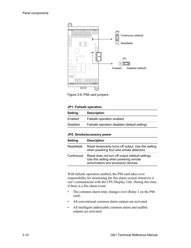
Panel components
3.10 QS1 Technical Reference Manual
Enabled Disabled (default)
JP1
Continuous (default)
Resettable
JP2
Figure 3-8: PS6 card jumpers
JP1: Failsafe operation
Setting Description
Enabled Failsafe operation enabled
Disabled Failsafe operation disabled (default setting)
JP2: Smoke/accessory power
Setting Description
Resettable Reset temporarily turns off output. Use this setting when powering four-wire smoke detectors.
Continuous Reset does not turn off output (default setting). Use this setting when powering remote annunciators and accessory devices.
With failsafe operation enabled, the PS6 card takes over responsibility for monitoring the fire alarm system whenever it can’t communicate with the CPU/Display Unit. During this time, if there is a fire alarm event:
• The common alarm relay changes over (Relay 1 on the PS6 card)
• All conventional common alarm outputs are activated
• All intelligent addressable common alarm and audible outputs are activated
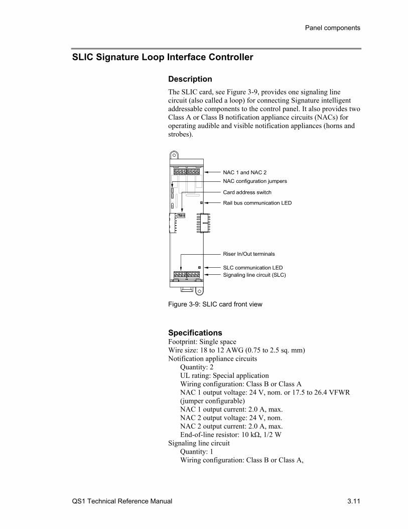
Panel components
QS1 Technical Reference Manual 3.11
SLIC Signature Loop Interface Controller
Description
The SLIC card, see Figure 3-9, provides one signaling line circuit (also called a loop) for connecting Signature intelligent addressable components to the control panel. It also provides two Class A or Class B notification appliance circuits (NACs) for operating audible and visible notification appliances (horns and strobes).
NAC 1 and NAC 2
NAC configuration jumpers
Card address switch
Rail bus communication LED
Riser In/Out terminals
SLC communication LEDSignaling line circuit (SLC)
Figure 3-9: SLIC card front view
Specifications Footprint: Single space Wire size: 18 to 12 AWG (0.75 to 2.5 sq. mm) Notification appliance circuits
Quantity: 2 UL rating: Special application Wiring configuration: Class B or Class A NAC 1 output voltage: 24 V, nom. or 17.5 to 26.4 VFWR (jumper configurable) NAC 1 output current: 2.0 A, max. NAC 2 output voltage: 24 V, nom. NAC 2 output current: 2.0 A, max. End-of-line resistor: 10 kΩ, 1/2 W
Signaling line circuit Quantity: 1 Wiring configuration: Class B or Class A,
Panel components
3.12 QS1 Technical Reference Manual
Capacity: Up to 250 devices T-taps: 124 Communication line voltage: 20.1 V peak-to-peak Communication line current: 0.421 mA, max. Circuit resistance: 65 Ω, max. Circuit capacitance: 0.3 μF, max.
Riser input voltage: 24 V, nom. Ground fault impedance: 2 kΩ Operating voltage: 24 VDC Current requirements
Standby current: 74 mA Alarm current: 134 mA (does not include NAC 1 current when JP1-2 is shorted to JP1-3)
Operating environment Temperature: 32 to 120°F (0 to 49°C) Humidity: 0 to 93% RH, noncondensing at 90°F (32°C)
See QuickStart Compatibility List (P/N 3100335) for the devices that you can connect to circuits rated special applications and their quantity.
Notification appliance circuits
The SLIC card provides two notification appliance circuits (NACs). They are labeled NAC 1 and NAC 2. Both NACs can be wired Class A or Class B as shown in Figure 3-10.
To operate notification appliances connected to NAC 2 you must connect the PS6 card’s AUX power output to the SLIC card’s riser input (RISER IN).
To operate notification appliances connected to NAC 1 you can configure the SLIC card to use the riser input signal or use 24 volts from the rail bus. For more information, see “Jumper settings” later in this topic.
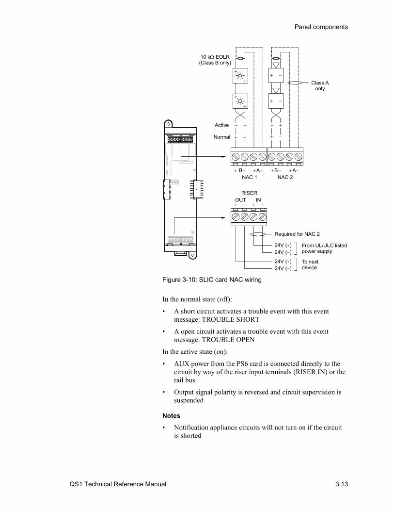
Panel components
QS1 Technical Reference Manual 3.13
A B A B NAC 1 NAC 2
RISERINOUT
Normal
Active
10 k EOLR(Class B only)
Class Aonly
From UL/ULC listedpower supply
To nextdevice
Required for NAC 2
24V ( )
24V ( )
24V ( )
24V ( )
Figure 3-10: SLIC card NAC wiring
In the normal state (off):
• A short circuit activates a trouble event with this event message: TROUBLE SHORT
• A open circuit activates a trouble event with this event message: TROUBLE OPEN
In the active state (on):
• AUX power from the PS6 card is connected directly to the circuit by way of the riser input terminals (RISER IN) or the rail bus
• Output signal polarity is reversed and circuit supervision is suspended
Notes
• Notification appliance circuits will not turn on if the circuit is shorted
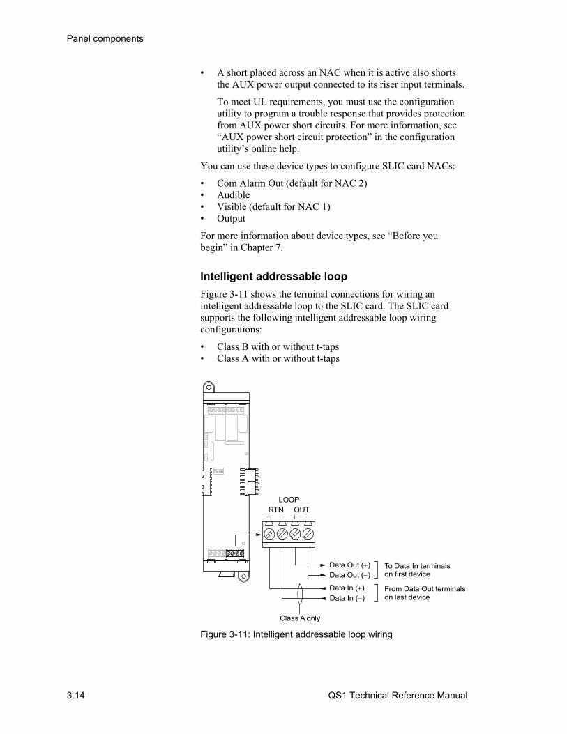
Panel components
3.14 QS1 Technical Reference Manual
• A short placed across an NAC when it is active also shorts the AUX power output connected to its riser input terminals.
To meet UL requirements, you must use the configuration utility to program a trouble response that provides protection from AUX power short circuits. For more information, see “AUX power short circuit protection” in the configuration utility’s online help.
You can use these device types to configure SLIC card NACs:
• Com Alarm Out (default for NAC 2) • Audible • Visible (default for NAC 1) • Output
For more information about device types, see “Before you begin” in Chapter 7.
Intelligent addressable loop
Figure 3-11 shows the terminal connections for wiring an intelligent addressable loop to the SLIC card. The SLIC card supports the following intelligent addressable loop wiring configurations:
• Class B with or without t-taps • Class A with or without t-taps
LOOPOUTRTN
Class A only
Data Out ( )
Data In ( )
Data Out ( )
Data In ( )From Data Out terminalson last device
To Data In terminalson first device
Figure 3-11: Intelligent addressable loop wiring
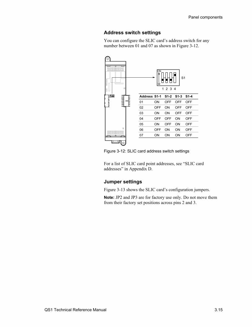
Panel components
QS1 Technical Reference Manual 3.15
Address switch settings
You can configure the SLIC card’s address switch for any number between 01 and 07 as shown in Figure 3-12.
Address S1-1 S1-2 S1-3 S1-4
01 ON OFF OFF OFF
02 OFF ON OFF OFF
03 ON ON OFF OFF
04 OFF OFF ON OFF
05 ON OFF ON OFF
06 OFF ON ON OFF
07 ON ON ON OFF
S1
ON
1 2 3 4
Figure 3-12: SLIC card address switch settings
For a list of SLIC card point addresses, see “SLIC card addresses” in Appendix D.
Jumper settings
Figure 3-13 shows the SLIC card’s configuration jumpers.
Note: JP2 and JP3 are for factory use only. Do not move them from their factory set positions across pins 2 and 3.

Panel components
3.16 QS1 Technical Reference Manual
3
2
1Do not change
3
2
1
3
2
1
JP1
JP2
JP3
Figure 3-13: SLIC card jumpers
JP1: NAC 1 signal select
Setting Description
1 to 2 24V from the rail bus
2 to 3 24V from the RISER IN terminals (default setting)
Two-wire smoke detector application
Retrofitting a fire alarm system typically requires incorporating the protected premises’ existing two-wire smoke detector circuits. To connect two-wire smoke detectors to an intelligent addressable loop you need a 2-SMK and a SIGA-UM configured with one of these personalities:
Personality Description
13 Use with Class B initiating device circuits connected to two-wire smoke detectors and dry contact initiating devices. Personality 13 does not support alarm verification.
14 Use with Class B initiating device circuits connected to two-wire smoke detectors only. Personality 14 supports alarm verification.
20 Use with Class A initiating device circuits connected to two-wire smoke detectors and dry contact initiating devices. Personality 20 does not support alarm verification.
Panel components
QS1 Technical Reference Manual 3.17
Personality Description
21 Use with Class A initiating device circuits connected to two-wire smoke detectors only. Personality 21supports alarm verification.
Note: Do not install more than 15 SIGA-UMs configured for two-wire smoke detectors on a loop; no more than 7 if isolating devices are also installed.
To install this application:
1. Wire the 2-SMK and SIGA-UM as shown in Figure 3-14.
2. Configure the SIGA-UM’s first address as follows:
Device type: Alarm Active
Personality: See above table
3. Configure the SIGA-UM’s second address as follows:
Device type: Monitor
Personality: None
4. Install the jumper on the SIGA-UM across pins 1 and 2 as shown in Figure 3-14.
5. Set JP2 on the PS6 card for continuous 24 volts.
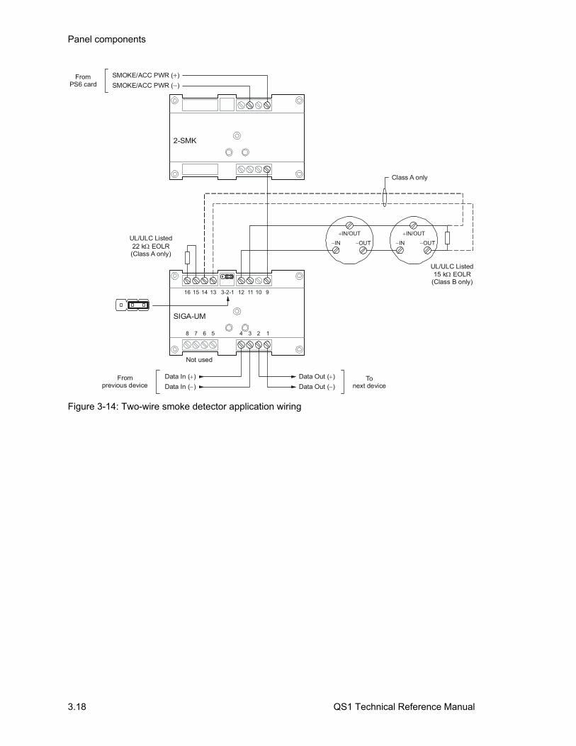
Panel components
3.18 QS1 Technical Reference Manual
2-SMK
12345678
1112 9101516 1314 3-2-1
SIGA-UM
IN OUT
Class A only
Data In ( )
Data In ( )
Not used
Data Out ( )
Data Out ( )
FromPS6 card
SMOKE/ACC PWR ( )SMOKE/ACC PWR ( )
UL/ULC Listed22 k EOLR(Class A only)
UL/ULC Listed15 k EOLR
(Class B only)
Fromprevious device
Tonext device
IN/OUT
IN OUT
IN/OUT
Figure 3-14: Two-wire smoke detector application wiring
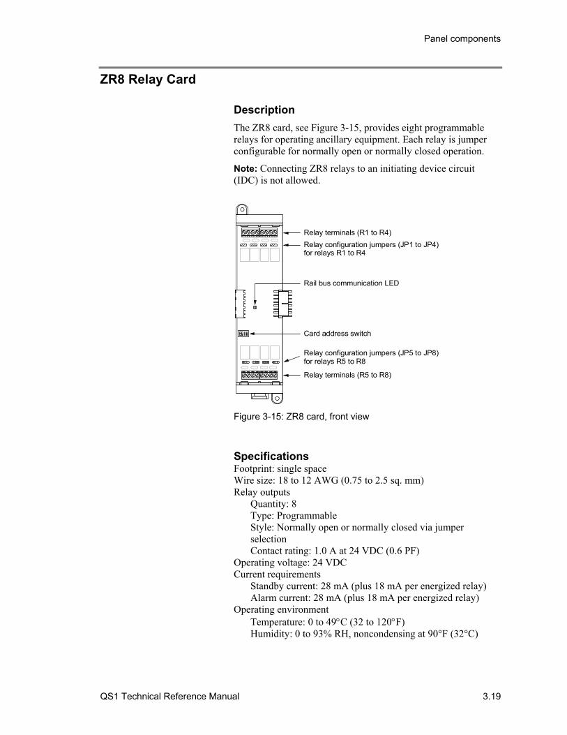
Panel components
QS1 Technical Reference Manual 3.19
ZR8 Relay Card
Description
The ZR8 card, see Figure 3-15, provides eight programmable relays for operating ancillary equipment. Each relay is jumper configurable for normally open or normally closed operation.
Note: Connecting ZR8 relays to an initiating device circuit (IDC) is not allowed.
Relay terminals (R1 to R4)
Rail bus communication LED
Card address switch
Relay terminals (R5 to R8)
Relay configuration jumpers (JP1 to JP4)for relays R1 to R4
Relay configuration jumpers (JP5 to JP8)for relays R5 to R8
Figure 3-15: ZR8 card, front view
Specifications Footprint: single space Wire size: 18 to 12 AWG (0.75 to 2.5 sq. mm) Relay outputs
Quantity: 8 Type: Programmable Style: Normally open or normally closed via jumper selection Contact rating: 1.0 A at 24 VDC (0.6 PF)
Operating voltage: 24 VDC Current requirements
Standby current: 28 mA (plus 18 mA per energized relay) Alarm current: 28 mA (plus 18 mA per energized relay)
Operating environment Temperature: 0 to 49C (32 to 120F) Humidity: 0 to 93% RH, noncondensing at 90°F (32°C)
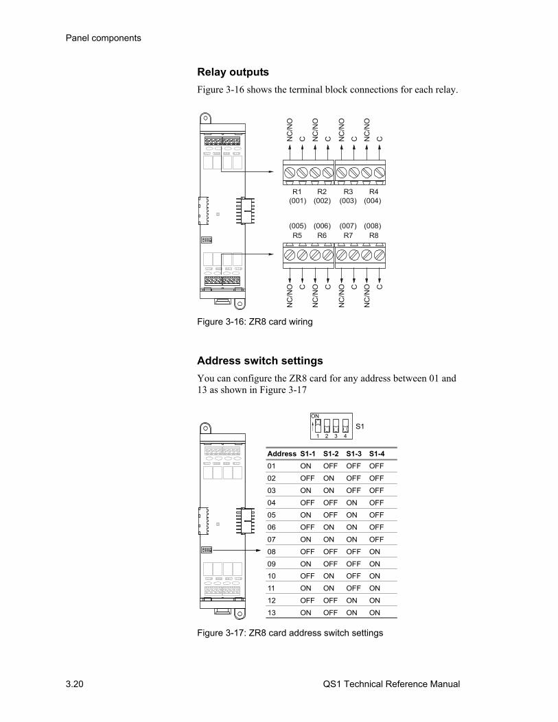
Panel components
3.20 QS1 Technical Reference Manual
Relay outputs
Figure 3-16 shows the terminal block connections for each relay.
R4R3R2(001) (003)(002) (004)
R5 R8R7R6(005) (007)(006) (008)
NC
/NO
C NC
/NO
C NC
/NO
C NC
/NO
C
NC
/NO C
NC
/NO C
NC
/NO C
NC
/NO C
Figure 3-16: ZR8 card wiring
Address switch settings
You can configure the ZR8 card for any address between 01 and 13 as shown in Figure 3-17
Address S1-1 S1-2 S1-3 S1-4
01 ON OFF OFF OFF
02 OFF ON OFF OFF
03 ON ON OFF OFF
04 OFF OFF ON OFF
05 ON OFF ON OFF
06 OFF ON ON OFF
07 ON ON ON OFF
08 OFF OFF OFF ON
09 ON OFF OFF ON
10 OFF ON OFF ON
11 ON ON OFF ON
12 OFF OFF ON ON
13 ON OFF ON ON
1 2 3 4
S1
ON
Figure 3-17: ZR8 card address switch settings
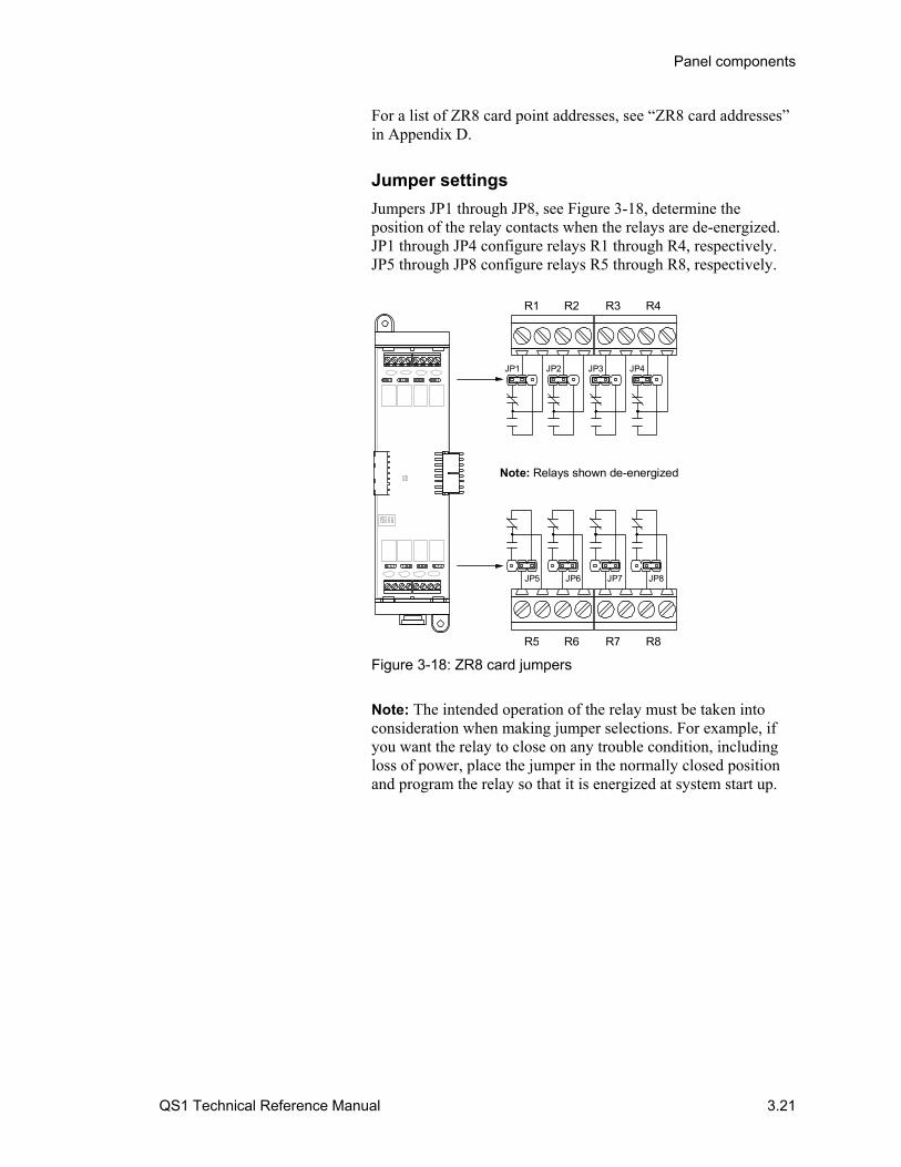
Panel components
QS1 Technical Reference Manual 3.21
For a list of ZR8 card point addresses, see “ZR8 card addresses” in Appendix D.
Jumper settings
Jumpers JP1 through JP8, see Figure 3-18, determine the position of the relay contacts when the relays are de-energized. JP1 through JP4 configure relays R1 through R4, respectively. JP5 through JP8 configure relays R5 through R8, respectively.
JP6JP5 JP7 JP8
R1 R4R3R2
R5 R8R7R6
JP1 JP2 JP3 JP4
Note: Relays shown de-energized
Figure 3-18: ZR8 card jumpers
Note: The intended operation of the relay must be taken into consideration when making jumper selections. For example, if you want the relay to close on any trouble condition, including loss of power, place the jumper in the normally closed position and program the relay so that it is energized at system start up.

Panel components
3.22 QS1 Technical Reference Manual
DLD Dual Line Dialer Card
Description
The DLD card, Figure 3-19, provides two telephone line connections for transmitting system status changes to one or two compatible digital alarm communicator receivers (DACRs) over the public switched telephone network. The DLD card can transmit status changes in Contact ID and 4/2 formats to eight subscriber accounts.
Line 2 jack
Rail bus communication LED
Tx Out LEDRx In LED
Line 1 jack
Figure 3-19: DLD card, front view
Specifications Footprint: Single space Ground fault impedance: 10 kΩ Operating voltage: 24 VDC Current requirements
Standby: 13 mA Dialing: 27 mA
Operating environment Temperature: 0 to 49C (32 to120F) Humidity: 0 to 93% RH, noncondensing at 90°F (32°C)
Address switch settings
The DLD card does not have an address switch for assigning card addresses. The DLD card’s card address is factory set at 14 and can’t be changed.
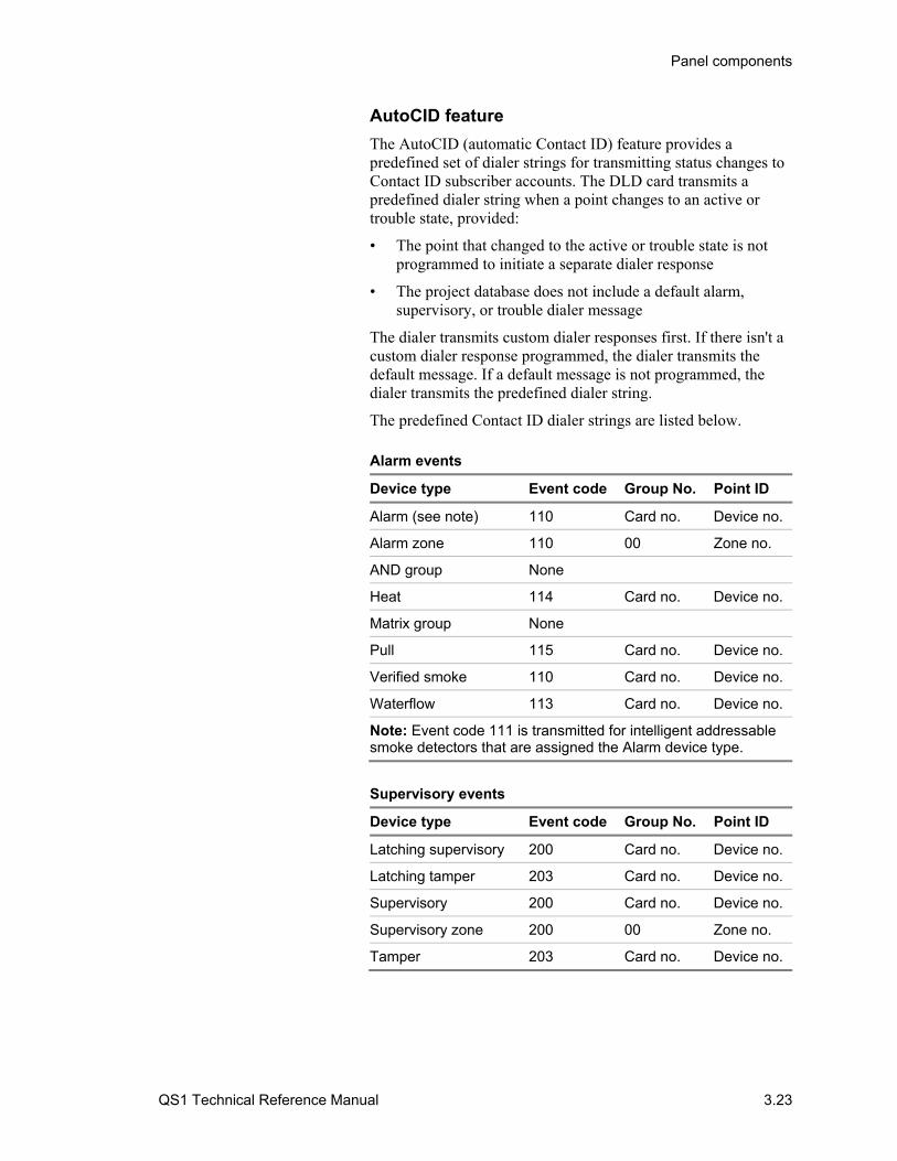
Panel components
QS1 Technical Reference Manual 3.23
AutoCID feature
The AutoCID (automatic Contact ID) feature provides a predefined set of dialer strings for transmitting status changes to Contact ID subscriber accounts. The DLD card transmits a predefined dialer string when a point changes to an active or trouble state, provided:
• The point that changed to the active or trouble state is not programmed to initiate a separate dialer response
• The project database does not include a default alarm, supervisory, or trouble dialer message
The dialer transmits custom dialer responses first. If there isn't a custom dialer response programmed, the dialer transmits the default message. If a default message is not programmed, the dialer transmits the predefined dialer string.
The predefined Contact ID dialer strings are listed below. Alarm events
Device type Event code Group No. Point ID
Alarm (see note) 110 Card no. Device no.
Alarm zone 110 00 Zone no.
AND group None
Heat 114 Card no. Device no.
Matrix group None
Pull 115 Card no. Device no.
Verified smoke 110 Card no. Device no.
Waterflow 113 Card no. Device no.
Note: Event code 111 is transmitted for intelligent addressable smoke detectors that are assigned the Alarm device type.
Supervisory events
Device type Event code Group No. Point ID
Latching supervisory 200 Card no. Device no.
Latching tamper 203 Card no. Device no.
Supervisory 200 Card no. Device no.
Supervisory zone 200 00 Zone no.
Tamper 203 Card no. Device no.

Panel components
3.24 QS1 Technical Reference Manual
Trouble events
Description Event code Group No. Point ID
Detector trouble 380 Card no. Device no.
Device disable 570 Card no. Device no.
Circuit trouble 373 Card no. Device no.
Zone trouble 300 00 Zone no.
Zone disable 570 00 Zone no.
Service group test 607 00 Service no.
Peripheral communication fault
330 00 000
Battery charger fault 302 00 000
Battery fault 302 00 000
Auxiliary power output shorted
320 00 000
Primary AC power failure
301 00 000
Excessive battery current
302 00 000
Ground fault (SIGA devices only)
310 Card no. Device no.
DLD Line 1 ground fault
570 14 017
DLD Line 2 ground fault
570 14 018
All other ground faults 310 00 000
Loop wiring problem 331 Card no. 000
Loop ground fault 310 Card no. 000
TELCO Line 1 fault 351 00 000
TELCO Line 2 fault 352 00 000
CMS receiver fault 354 00 000
Periodic test (system normal)
602 00 000
Periodic test (system abnormal)
608 00 000
System test - Drill 604 00 000
All other troubles 300 00 000
All other disables 570 Card no. Device no.

Panel components
QS1 Technical Reference Manual 3.25
Wiring
The DLD card typically connects to an RJ-31X block using an 8-position, 4-conductor modular cord. Wire the RJ-31X block as shown in Figure 3-20.
Note: Install a listed secondary telephone protector between the telco network and the DLD card. The DLD card must be the next piece of equipment that connects to the telephone company (TELCO) telephone lines.
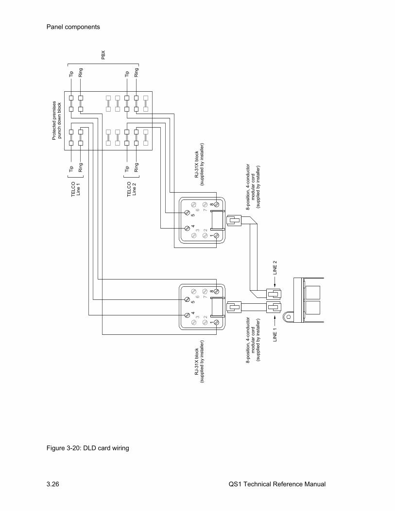
Panel components
3.26 QS1 Technical Reference Manual
Tip
Rin
g
Tip
Rin
g
Tip
Rin
g
Tip
Rin
g
Pro
tect
ed p
rem
ises
pun
ch d
own
bloc
k
TE
LCO
Line
1
TE
LCO
Line
2
PB
X
RJ-
31X
blo
ck(s
uppl
ied
by
inst
alle
r)
8-p
osi
tion,
4-c
ondu
ctor
mod
ula
r co
rd(s
upp
lied
by
inst
alle
r)
LIN
E 1
234
5
76
81
LIN
E 2
234
5
76
81
RJ-
31X
blo
ck(s
upp
lied
by in
stal
ler)
8-p
ositi
on,
4-c
ondu
cto
rm
odu
lar
cord
(su
pplie
d b
y in
stal
ler)
Figure 3-20: DLD card wiring
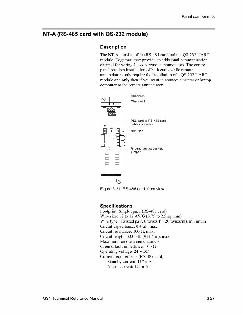
Panel components
QS1 Technical Reference Manual 3.27
NT-A (RS-485 card with QS-232 module)
Description
The NT-A consists of the RS-485 card and the QS-232 UART module. Together, they provide an additional communication channel for wiring Class A remote annunciators. The control panel requires installation of both cards while remote annunciators only require the installation of a QS-232 UART module and only then if you want to connect a printer or laptop computer to the remote annunciator.
Not used
Ground fault supervisionjumper
Channel 1
Channel 2
PS6 card to RS-485 cardcable connector
Figure 3-21: RS-485 card, front view
Specifications Footprint: Single space (RS-485 card) Wire size: 18 to 12 AWG (0.75 to 2.5 sq. mm) Wire type: Twisted pair, 6 twists/ft. (20 twists/m), minimum Circuit capacitance: 0.4 μF, max. Circuit resistance: 100 Ω, max. Circuit length: 3,000 ft. (914.4 m), max. Maximum remote annunciators: 8 Ground fault impedance: 10 kΩ Operating voltage: 24 VDC Current requirements (RS-485 card)
Standby current: 117 mA Alarm current: 121 mA
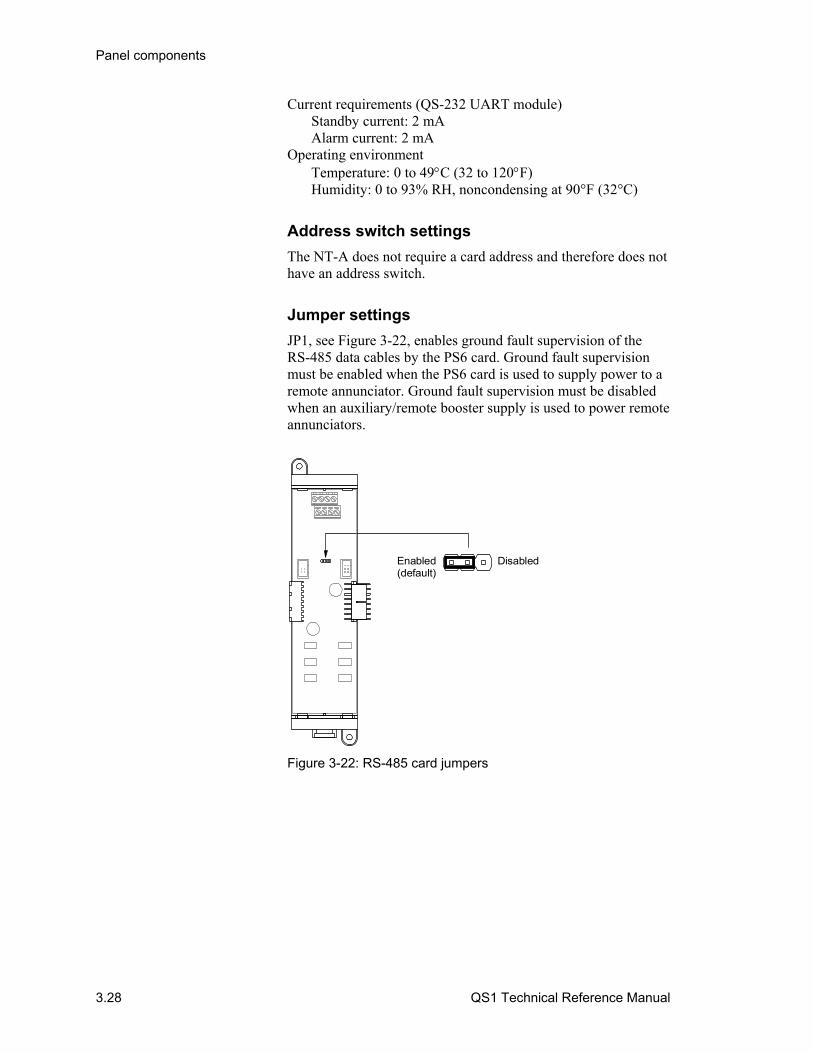
Panel components
3.28 QS1 Technical Reference Manual
Current requirements (QS-232 UART module) Standby current: 2 mA Alarm current: 2 mA
Operating environment Temperature: 0 to 49C (32 to 120F) Humidity: 0 to 93% RH, noncondensing at 90°F (32°C)
Address switch settings
The NT-A does not require a card address and therefore does not have an address switch.
Jumper settings
JP1, see Figure 3-22, enables ground fault supervision of the RS-485 data cables by the PS6 card. Ground fault supervision must be enabled when the PS6 card is used to supply power to a remote annunciator. Ground fault supervision must be disabled when an auxiliary/remote booster supply is used to power remote annunciators.
Enabled(default)
Disabled
Figure 3-22: RS-485 card jumpers
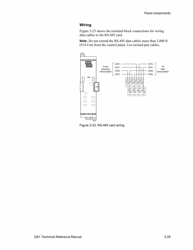
Panel components
QS1 Technical Reference Manual 3.29
Wiring
Figure 3-23 shows the terminal block connections for wiring data cables to the RS-485 card.
Note: Do not extend the RS-485 data cables more than 3,000 ft (914.4 m) from the control panel. Use twisted pair cables.
CH2
CH1
CH1
CH2
Tonext
annunciatorCH2
CH1
CH1
CH2
Fromprevious
annunciator
Figure 3-23: RS-485 card wiring
Panel components
3.30 QS1 Technical Reference Manual
LED/switch cards LED/switch cards can be used for zone annunciation, point annunciation, or manual override controls. When an LED/switch card is used for zone annunciation:
• The red Alarm LED is used to indicate an active fire alarm zone
• The yellow Active LED is used to indicate an active supervisory or monitor zone
• The yellow trouble LED is used to indicate a zone trouble, a zone disablement, and a zone in test
• The switch, if available, brings up the zone’s location description on the CPU/Display Unit
Note: In a zoned fire alarm system, the LED/switch card closest to the CPU/Display Unit is typically assigned to annunciator group 1, and the next is assigned to annunciator group 2.
For point annunciation and manual override controls, you must program the LED/switch cards using the configuration utility. For more information, refer to the configuration utility’s online Help.
For a list of LED/switch card addresses, see “LED/switch card addresses” in Appendix D.
SL30 card
The SL30 card, see Figure 3-24, provides 30 groups of LEDs and switches and is typically used for zone annunciation. Each LED-switch group consists of a red and a yellow LED under the left lens, a yellow LED under the right lens, and a switch. The switches are numbered 1 to 30.

Panel components
QS1 Technical Reference Manual 3.31
Switch
Alarm LED (red) orActive LED (yellow)
Fault LED (yellow)
Typical eachLED-switch group
1
2
3
4
5
6
7
8
9
10
11
12
13
14
15
16
17
18
19
20
21
22
23
24
25
26
27
28
29
30
Figure 3-24: SL30 card, front view
SL30-1 card
The SL30-1 card, see Figure 3-26, provides 30 groups of LEDs and switches and is typically used for zone annunciation. Each LED-switch group consists of a red and a yellow LED under the left lens, a yellow LED under the right lens, and a switch. The switches are numbered 31 to 60.
Switch
Alarm LED (red) orActive LED (yellow)
Fault LED (yellow)
Typical eachLED-switch group
31
32
33
34
35
36
37
38
39
40
41
42
43
44
45
46
47
48
49
50
51
52
53
54
55
56
57
58
59
60
Figure 3-25: SL30-1 card, front view
SL30L card
The SL30L card, see Figure 3-26, provides 30 groups of LEDs and is typically used for zone or point annunciation when custom labeling is desired. Each LED-switch group includes a red and a yellow LED under the left lens, a yellow LED under the right

Panel components
3.32 QS1 Technical Reference Manual
lens, and a label window. Label inserts are provided with the SL30L card so you can label each LED-switch group.
Label insertwindow
Alarm LED (red) orActive LED (yellow)
Fault LED (yellow)
Typical eachLED-switch group
Figure 3-26: SL30L card, front view
SL20L5S
The SL20L5S card, see Figure 3-27, provides 20 groups of LEDs without switches and 5 groups of LEDs with switches. It is typically used for point annunciation and manual override controls. Each LED-switch group includes a red and a yellow LED under the left lens and a yellow LED under the right lens. LED-switch groups 21 through 25 also include a switch. Card inserts are provided with the SL20L5S card so you can label each LED-switch group.
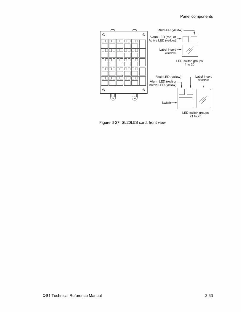
Panel components
QS1 Technical Reference Manual 3.33
LED-switch groups21 to 25
Label insertwindow
Label insertwindow
Alarm LED (red) orActive LED (yellow)
Fault LED (yellow)
LED-switch groups1 to 20
Switch
Alarm LED (red) orActive LED (yellow)
Fault LED (yellow)
Figure 3-27: SL20L5S card, front view

Panel components
3.34 QS1 Technical Reference Manual
QS1 Technical Reference Manual 4.1
Chapter 4 Accessories
Summary
This chapter provides technical descriptions of the accessories that can be connected to the control panel.
Content
CDR-3 Bell Coder • 4.2 Description • 4.2 Specifications • 4.2 Operation • 4.2 Switch settings • 4.4 Jumper settings • 4.5 Coded alarm signaling application • 4.5
RPM Reverse Polarity Module • 4.8 Description • 4.8 Specifications • 4.8 Remote station protective signaling system application • 4.8
CTM City Tie Module • 4.12 Description • 4.12 Specifications • 4.12 Auxiliary protective signaling system application • 4.12
IOP3A RS-232 Isolator • 4.14 Description • 4.14 Specifications • 4.14 Jumper settings • 4.14 Switch settings • 4.15 Connecting a printer and a CDR-3 to the RS-232 port • 4.16
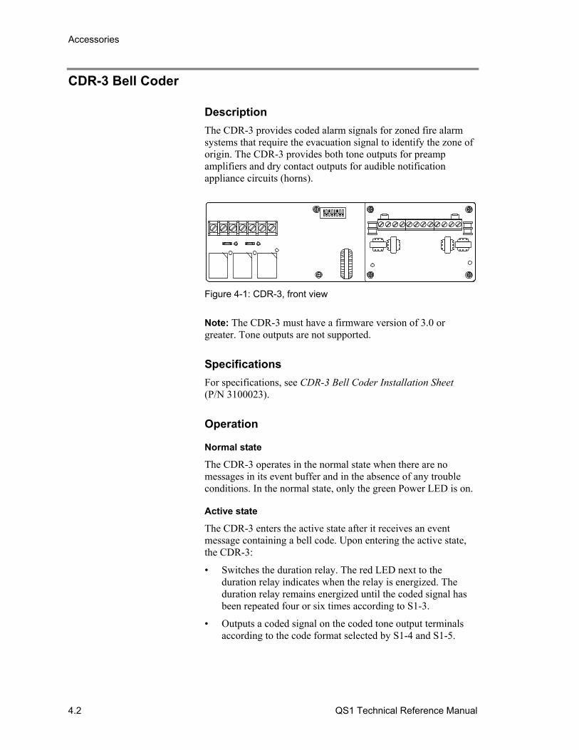
Accessories
4.2 QS1 Technical Reference Manual
CDR-3 Bell Coder
Description
The CDR-3 provides coded alarm signals for zoned fire alarm systems that require the evacuation signal to identify the zone of origin. The CDR-3 provides both tone outputs for preamp amplifiers and dry contact outputs for audible notification appliance circuits (horns).
Figure 4-1: CDR-3, front view
Note: The CDR-3 must have a firmware version of 3.0 or greater. Tone outputs are not supported.
Specifications
For specifications, see CDR-3 Bell Coder Installation Sheet (P/N 3100023).
Operation
Normal state
The CDR-3 operates in the normal state when there are no messages in its event buffer and in the absence of any trouble conditions. In the normal state, only the green Power LED is on.
Active state
The CDR-3 enters the active state after it receives an event message containing a bell code. Upon entering the active state, the CDR-3:
• Switches the duration relay. The red LED next to the duration relay indicates when the relay is energized. The duration relay remains energized until the coded signal has been repeated four or six times according to S1-3.
• Outputs a coded signal on the coded tone output terminals according to the code format selected by S1-4 and S1-5.

Accessories
QS1 Technical Reference Manual 4.3
• Toggles the bell code relay according to the code format selected by S1-4 and S1-5. The red LED next to the bell code relay indicates when the relay is energized.
After the coded signal has been repeated the selected number of rounds, the CDR-3:
• Switches the duration relay to its normal position
• Outputs an evacuation signal on the temporal tone output terminals according to the evacuation signal type selected by S1-1 and S1-2.
• Toggles the temporal relay according to the evacuation signal selected by S1-1 and S1-2. The red LED next to the temporal relay indicates when the relay is energized.
Trouble state
The CDR-3 enters the trouble state under the following conditions:
• An open circuit on the coded tone output • An open circuit on the temporal tone output • A CPU fault • An RS-232 communication fault
Upon entering the trouble state, the CDR-3:
• Outputs the selected evacuation signal on the temporal tone output terminals
• Toggles the temporal relay
• Closes the trouble relay
• Turns the yellow Trouble LED on
Coded signal formats
The four formats you can select using S1-4 and S1-5 are described below.
Format 1: Coded signal is identical to the bell code. Example: A bell code of 5-5-5-5 generates a coded signal consisting of 5 pulses and a pause, then 5 pulses and a pause, then 5 pulses and a pause, and then 5 pulses and a pause.
Format 2: Coded signal combines the first and second digits of the bell code. Example: A bell code of 5-5-5-5 generates a coded signal consisting of 10 pulses and a pause, then 5 pulses and a pause, and then 5 pulses and a pause.
Format 3: Coded signal combines the second and third digits of the bell code. Example: A bell code of 5-5-5-5 generates a coded signal consisting of 5 pulses and a pause, then 10 pulses and a pause, and then 5 pulses and a pause.

Accessories
4.4 QS1 Technical Reference Manual
Format 4: Coded signal combines the third and fourth digits of the bell code. Example: A bell code of 5-5-5-5 generates a coded signal consisting of 5 pulses and a pause, then 5 pulses and a pause, and then 10 pulses and a pause.
Switch settings
Switch S1 is used to configure the evacuation signal, code sequence, and RS-232 communication as described below.
Evacuationsignal
Codesequence RS-232
ON
1 2 3 4
S1
5 6 7 8
Evacuation signal
S1-1 S1-2 Description
OFF OFF Temporal tone (3-3-3)
OFF ON Fast march tone (120 bpm)
ON ON Slow march tone (20 bpm)
Code sequence
S1-3 S1-4 S1-5 Description
OFF 6 rounds
ON 4 rounds
OFF OFF Format 1 (0-9, 0-9, 0-9, 0-9)
ON OFF Format 2 (0-18, 0-9, 0-9)
OFF ON Format 3 (0-9, 0-18, 0-9)
ON ON Format 4 (0-9, 0-9, 0-18)
RS-232 communication
S1-6 S1-7 S1-8 Description
OFF Even parity
ON No parity
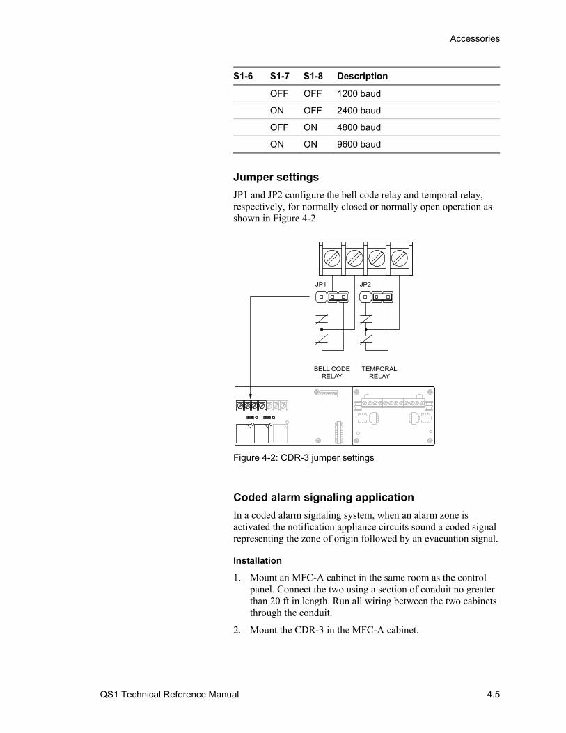
Accessories
QS1 Technical Reference Manual 4.5
S1-6 S1-7 S1-8 Description
OFF OFF 1200 baud
ON OFF 2400 baud
OFF ON 4800 baud
ON ON 9600 baud
Jumper settings
JP1 and JP2 configure the bell code relay and temporal relay, respectively, for normally closed or normally open operation as shown in Figure 4-2.
TEMPORALRELAY
BELL CODERELAY
JP1 JP2
Figure 4-2: CDR-3 jumper settings
Coded alarm signaling application
In a coded alarm signaling system, when an alarm zone is activated the notification appliance circuits sound a coded signal representing the zone of origin followed by an evacuation signal.
Installation
1. Mount an MFC-A cabinet in the same room as the control panel. Connect the two using a section of conduit no greater than 20 ft in length. Run all wiring between the two cabinets through the conduit.
2. Mount the CDR-3 in the MFC-A cabinet.
Accessories
4.6 QS1 Technical Reference Manual
3. Wire as shown in Figure 4-3. Install a 10 kΩ EOLR across TB2-1 and TB2-2, and across TB2-11 and TB2-12.
Note: If a printer is also connected to the control panel, install an IOP3A isolator module.
Configuration
1. Configure the CDR-3 as follows:
• Set S1-1 and S1-2 for the required evacuation signal, typically Temporal (3-3-3)
• Set S1-3 for the required number of rounds, typically 4
• Set S1-4 and S1-5 for the required format
• Set S1-6 for No Parity
• Set S1-7 and S1-8 for 9600 baud
2. Set JP2 on the PS6 card for continuous 24 volts.
3. Configure the SLIC card as follows:
• Set JP1 so NAC 1 uses 24 volts from the rail bus
• Configure NAC 1 as a visible device type
• Configure NAC 2 as a common alarm output device type
4. Configure the auxiliary/booster supply to use the CDR-3. For more information, refer to the CDR-3 applications in the auxiliary/booster supply’s technical reference manual.
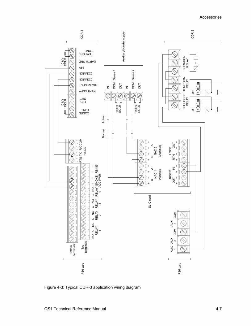
Accessories
QS1 Technical Reference Manual 4.7
IN IN
DU
RA
TIO
NR
EL
AY
TE
MP
OR
AL
RE
LAY
BE
LL
CO
DE
RE
LAY
JP1
JP2
AU
X1
AU
X2
CO
MA
UX
3C
OM
NA
C 1
(Vis
ible
)
OU
TIN
RT
NO
UT
RE
LAY
1R
ELA
Y2
RE
LAY
3R
ELA
Y4
SM
OK
EA
CC
PW
R
RS
485
RT
ST
XR
XC
OM
RS
232
Top
term
inal
s
Bo
ttom
term
inal
s
CN
OC
NO
CN
ON
ON
CC
PS
6 c
ard
TEMPORLTONE
EARTH GND
CODEDTONE
24V
COMMON
COMMON
RS232 INPUT
PRINT SUPV
TRBLOUT
10 k
EO
LR
10
kE
OLR
CD
R-3
PS
6 c
ard
BA
RIS
ER
LOO
P
NA
C 2
BA
CD
R-3
(Au
dib
le)
Nor
mal
Act
ive
Aux
iliar
y/bo
oste
r su
pply
SL
IC c
ard
CO
M
OU
T
CO
M
OU
T
Sen
se 1
Sen
se 2
10
kE
OLR
10
kE
OLR
Figure 4-3: Typical CDR-3 application wiring diagram
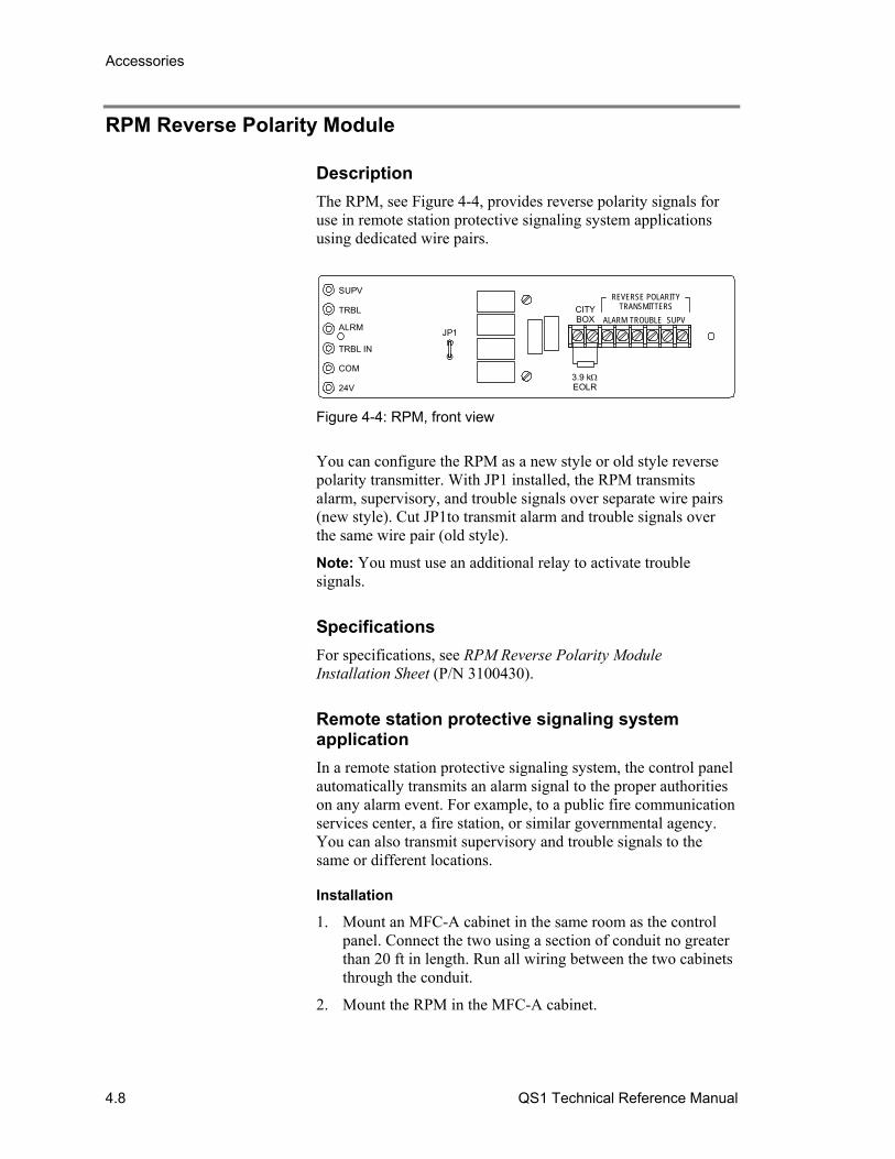
Accessories
4.8 QS1 Technical Reference Manual
RPM Reverse Polarity Module
Description
The RPM, see Figure 4-4, provides reverse polarity signals for use in remote station protective signaling system applications using dedicated wire pairs.
SUPV
TRBL
ALRM
TRBL IN
COM
24V
JP1
CITYBOX ALARM TROUBLE SUPV
REVERSE POLARITYTRANSMITTERS
3.9 kEOLR
Figure 4-4: RPM, front view
You can configure the RPM as a new style or old style reverse polarity transmitter. With JP1 installed, the RPM transmits alarm, supervisory, and trouble signals over separate wire pairs (new style). Cut JP1to transmit alarm and trouble signals over the same wire pair (old style).
Note: You must use an additional relay to activate trouble signals.
Specifications
For specifications, see RPM Reverse Polarity Module Installation Sheet (P/N 3100430).
Remote station protective signaling system application
In a remote station protective signaling system, the control panel automatically transmits an alarm signal to the proper authorities on any alarm event. For example, to a public fire communication services center, a fire station, or similar governmental agency. You can also transmit supervisory and trouble signals to the same or different locations.
Installation
1. Mount an MFC-A cabinet in the same room as the control panel. Connect the two using a section of conduit no greater than 20 ft in length. Run all wiring between the two cabinets through the conduit.
2. Mount the RPM in the MFC-A cabinet.
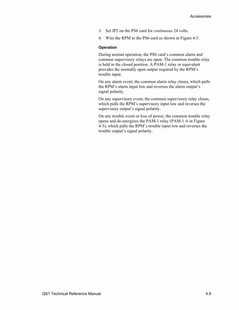
Accessories
QS1 Technical Reference Manual 4.9
3. Set JP2 on the PS6 card for continuous 24 volts.
4. Wire the RPM to the PS6 card as shown in Figure 4-5.
Operation
During normal operation, the PS6 card’s common alarm and common supervisory relays are open. The common trouble relay is held in the closed position. A PAM-1 relay or equivalent provides the normally open output required by the RPM’s trouble input.
On any alarm event, the common alarm relay closes, which pulls the RPM’s alarm input low and reverses the alarm output’s signal polarity.
On any supervisory event, the common supervisory relay closes, which pulls the RPM’s supervisory input low and reverses the supervisory output’s signal polarity.
On any trouble event or loss of power, the common trouble relay opens and de-energizes the PAM-1 relay (PAM-1 A in Figure 4-5), which pulls the RPM’s trouble input low and reverses the trouble output’s signal polarity.
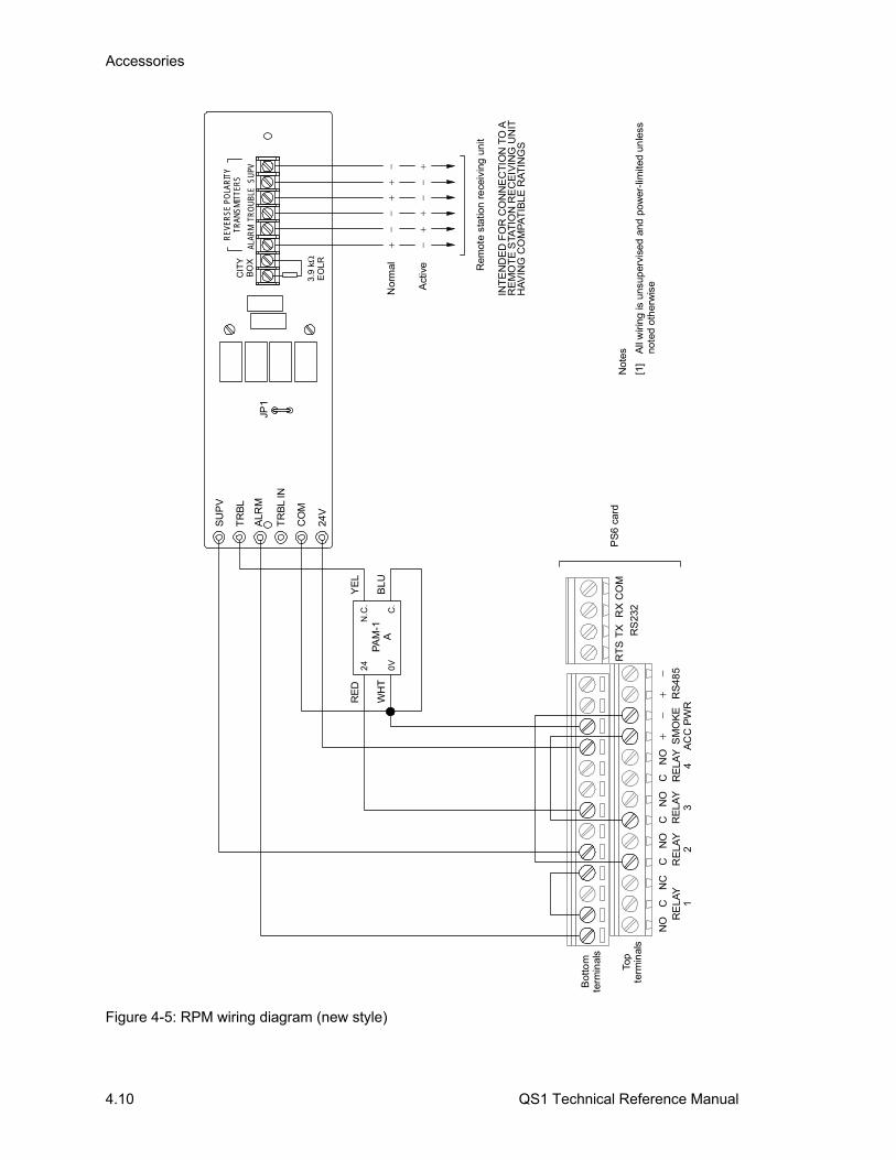
Accessories
4.10 QS1 Technical Reference Manual
RE
LAY
1R
ELA
Y2
RE
LAY
3R
ELA
Y4
SM
OK
EA
CC
PW
R
RS
485
RT
ST
XR
XC
OM
RS
232
Top
term
inal
s
Bot
tom
term
inal
s
N.C
.
C.
YE
L
BLU
RE
D
WH
T
24
0V
PA
M-1
A
CN
OC
NO
CN
ON
ON
CC
Nor
mal
Act
ive
SU
PV
TR
BL
ALR
M
TR
BL
IN
CO
M
24V
JP1
CIT
YB
OX
ALAR
MTR
OU
BLE
SUPV
REV
ERSE
PO
LAR
ITY
TRAN
SMIT
TER
S
3.9
kE
OL
R
PS
6 ca
rd
Rem
ote
stat
ion
re
ceiv
ing
unit
INT
EN
DE
D F
OR
CO
NN
EC
TIO
N T
O A
RE
MO
TE
STA
TIO
N R
EC
EIV
ING
UN
IT
HA
VIN
G C
OM
PA
TIB
LE R
AT
ING
S
Not
es
[1]
All
wiri
ng is
uns
uper
vise
d a
nd p
ower
-lim
ited
unle
ss
note
d ot
her
wis
e
Figure 4-5: RPM wiring diagram (new style)

Accessories
QS1 Technical Reference Manual 4.11
Nor
mal
Ala
rm
Rem
ote
sta
tion
rece
ivin
g u
nit
INT
EN
DE
D F
OR
CO
NN
EC
TIO
N T
O A
RE
MO
TE
STA
TIO
N R
EC
EIV
ING
UN
IT
HA
VIN
G C
OM
PA
TIB
LE R
AT
ING
S
Tro
uble
0V0V
RE
LAY
1R
ELA
Y2
RE
LAY
3R
ELA
Y4
SM
OK
EA
CC
PW
R
RS
485
RT
ST
XR
XC
OM
RS
232
Top
term
inal
s
Bot
tom
term
inal
s
N.C
.
C.
YE
L
BLU
RE
D
WH
T
24
0V
PA
M-1
A
CN
OC
NO
CN
ON
ON
CC
SU
PV
TR
BL
ALR
M
TR
BL
IN
CO
M
24V
JP1
CIT
YB
OX
ALAR
MTR
OU
BLE
SUPV
REV
ERSE
PO
LAR
ITY
TRAN
SMIT
TER
S
3.9
kE
OL
R
PS
6 ca
rdN
otes
[1]
All
wiri
ng is
uns
uper
vise
d a
nd p
ower
-lim
ited
unle
ss
note
d ot
her
wis
e
Figure 4-6: RPM wiring diagram (old style)
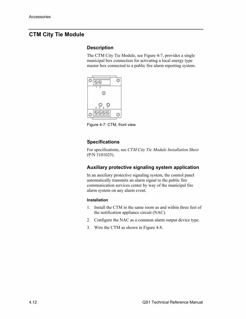
Accessories
4.12 QS1 Technical Reference Manual
CTM City Tie Module
Description
The CTM City Tie Module, see Figure 4-7, provides a single municipal box connection for activating a local energy type master box connected to a public fire alarm reporting system.
1234
21
Figure 4-7: CTM, front view
Specifications
For specifications, see CTM City Tie Module Installation Sheet (P/N 3101025).
Auxiliary protective signaling system application
In an auxiliary protective signaling system, the control panel automatically transmits an alarm signal to the public fire communication services center by way of the municipal fire alarm system on any alarm event.
Installation
1. Install the CTM in the same room as and within three feet of the notification appliance circuit (NAC).
2. Configure the NAC as a common alarm output device type.
3. Wire the CTM as shown in Figure 4-8.
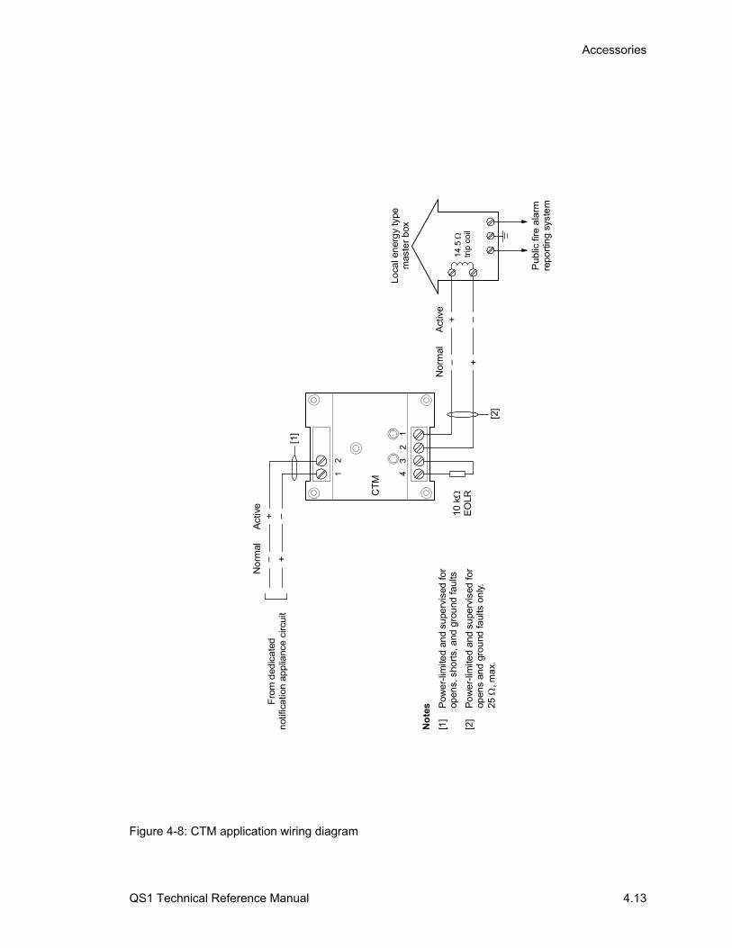
Accessories
QS1 Technical Reference Manual 4.13
CT
M
21
12
34
+ –N
orm
alA
ctiv
e
Fro
m d
edic
ate
dn
otifi
catio
n a
pp
lianc
e c
ircui
t
10 k
EO
LR
Pub
lic f
ire a
larm
rep
ort
ing
syst
em
Loca
l en
erg
y ty
pem
aste
r b
ox
14.
5 tr
ip c
oil
+ –
+ –N
orm
alA
ctiv
e+ –
[1]
[2]
No
tes
[1]
Po
we
r-lim
ited
and
supe
rvis
ed fo
r op
ens,
sho
rts,
and
gro
und
fau
lts
[2]
Po
we
r-lim
ited
and
supe
rvis
ed fo
r op
ens
and
gro
und
faul
ts o
nly
. 25
, m
ax.
Figure 4-8: CTM application wiring diagram
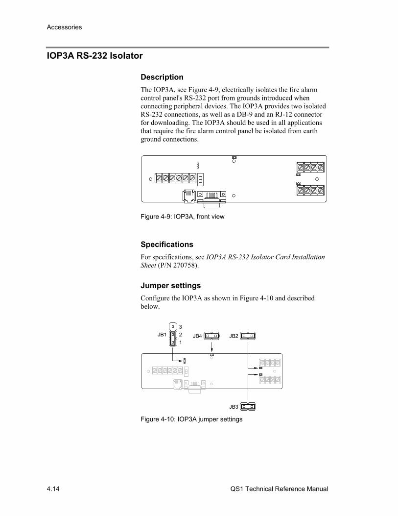
Accessories
4.14 QS1 Technical Reference Manual
IOP3A RS-232 Isolator
Description
The IOP3A, see Figure 4-9, electrically isolates the fire alarm control panel's RS-232 port from grounds introduced when connecting peripheral devices. The IOP3A provides two isolated RS-232 connections, as well as a DB-9 and an RJ-12 connector for downloading. The IOP3A should be used in all applications that require the fire alarm control panel be isolated from earth ground connections.
Figure 4-9: IOP3A, front view
Specifications
For specifications, see IOP3A RS-232 Isolator Card Installation Sheet (P/N 270758).
Jumper settings
Configure the IOP3A as shown in Figure 4-10 and described below.
3
2
1
JB1 JB4 JB2
JB3
Figure 4-10: IOP3A jumper settings
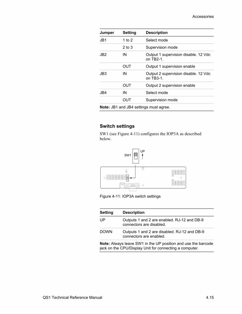
Accessories
QS1 Technical Reference Manual 4.15
Jumper Setting Description
JB1 1 to 2 Select mode
2 to 3 Supervision mode
JB2 IN Output 1 supervision disable. 12 Vdc on TB2-1.
OUT Output 1 supervision enable
JB3 IN Output 2 supervision disable. 12 Vdc on TB3-1.
OUT Output 2 supervision enable
JB4 IN Select mode
OUT Supervision mode
Note: JB1 and JB4 settings must agree.
Switch settings
SW1 (see Figure 4-11) configures the IOP3A as described below.
SW1UP
Figure 4-11: IOP3A switch settings
Setting Description
UP Outputs 1 and 2 are enabled. RJ-12 and DB-9 connectors are disabled.
DOWN Outputs 1 and 2 are disabled. RJ-12 and DB-9 connectors are enabled.
Note: Always leave SW1 in the UP position and use the barcode jack on the CPU/Display Unit for connecting a computer.
Accessories
4.16 QS1 Technical Reference Manual
Connecting a printer and a CDR-3 to the RS-232 port
In installations that have two peripheral devices connected to the control panel’s RS-232 port, such as a printer and a CDR-3, you need to install an IOP3A to divide the RS-232 transmission path.
1. Mount an MFC-A cabinet in the same room as the control panel. Connect the two using a section of conduit no greater than 20 ft in length. Run all wiring between the two cabinets through the conduit.
2. Mount the IOP3A and the CDR-3 in the MFC-A cabinet.
3. Wire as shown in Figure 4-12.
Note: If you use a power supply other than PS6 card, it must provide a continuous 24 Vdc and be UL/ULC listed for fire protective signaling systems.

Accessories
QS1 Technical Reference Manual 4.17
Alw
ays
lea
ve in
the
UP
po
siti
on TEMPORL
TONE
EARTH GND
CODEDTONE
24V
COMMON
COMMON
RS232 INPUT
PRINT SUPV
TRBLOUT
10 k
EO
LR
10
kE
OL
R
CD
R-3
RE
LA
Y1
RE
LAY
2R
ELA
Y3
RE
LAY
4
SM
OK
EA
CC
PW
R
RS
485
RT
ST
XR
XC
OM
RS
232
Top
term
ina
ls
Bot
tom
term
ina
ls
CN
OC
NO
CN
ON
ON
CC
PS
6ca
rd
IOP
3A
73
2D
B-2
5Pre
ar v
iew
Figure 4-12: IOP3A application wiring diagram

Accessories
4.18 QS1 Technical Reference Manual
QS1 Technical Reference Manual 5.1
Chapter 5 Operating instructions
Summary
This chapter provides instructions for operating the fire alarm system from the control panel CPU/Display Unit. It is intended for those who might be expected to operate the control panel in a fire alarm emergency.
Content
Logging on to the control panel • 5.2 Viewing status reports • 5.3 Viewing maintenance reports • 5.4 Viewing a history report • 5.5 Viewing alarm history reports • 5.6 Performing a lamp test • 5.7 Silencing the panel buzzer • 5.8 Resetting the fire alarm system • 5.9 Silencing alarm signals • 5.10 Sounding an alarm • 5.11 Disabling and enabling zones • 5.12 Disabling and enabling device addresses • 5.13 Switching detector alarm sensitivity • 5.14 Switching event message routes • 5.15 Changing the level 1 password • 5.16 Restarting the fire alarm system • 5.17

Operating instructions
5.2 QS1 Technical Reference Manual
Logging on to the control panel Logging on to the control panel gives you access to system commands that are otherwise restricted from view. Your login password determines which commands you can use, as follows.
• For level 2 commands, enter the level 2 password
• For level 3 commands, enter the level 3 password
• For level 4 commands, enter the level 4 password
For more information, see the topic “Command menu organization” in Chapter 2.
You don’t have to log on to the control panel to use level 1 commands. You don’t have to log on to the control panel to use level 2 commands if the Enable Control key is in the ON position.
The control panel lets you use the command menus for the password you entered until you log on with a different password or until the user time-out period expires (approximately three minutes). After the user time-out period expires, the control panel automatically returns to using the level 1 command menus.
To log on to the fire alarm system:
1. On the Main menu, choose Login.
2. Enter your password.
MAIN MENU 1)Status 2)Reports 3)Test 4)Login
ENTER PASSWORD XXXX
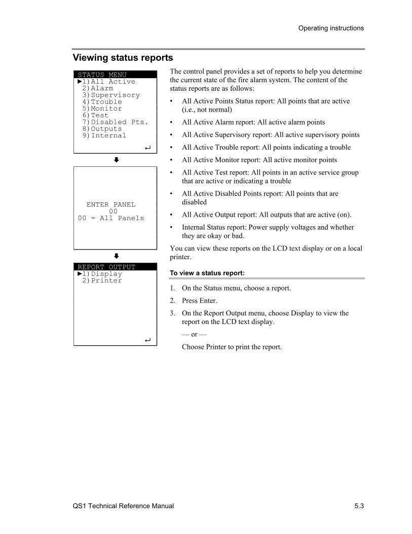
Operating instructions
QS1 Technical Reference Manual 5.3
Viewing status reports The control panel provides a set of reports to help you determine the current state of the fire alarm system. The content of the status reports are as follows:
• All Active Points Status report: All points that are active (i.e., not normal)
• All Active Alarm report: All active alarm points
• All Active Supervisory report: All active supervisory points
• All Active Trouble report: All points indicating a trouble
• All Active Monitor report: All active monitor points
• All Active Test report: All points in an active service group that are active or indicating a trouble
• All Active Disabled Points report: All points that are disabled
• All Active Output report: All outputs that are active (on).
• Internal Status report: Power supply voltages and whether they are okay or bad.
You can view these reports on the LCD text display or on a local printer.
To view a status report:
1. On the Status menu, choose a report.
2. Press Enter.
3. On the Report Output menu, choose Display to view the report on the LCD text display.
— or —
Choose Printer to print the report.
STATUS MENU 1)All Active 2)Alarm 3)Supervisory 4)Trouble 5)Monitor 6)Test 7)Disabled Pts. 8)Outputs 9)Internal
ENTER PANEL 00 00 = All Panels
REPORT OUTPUT 1)Display 2)Printer
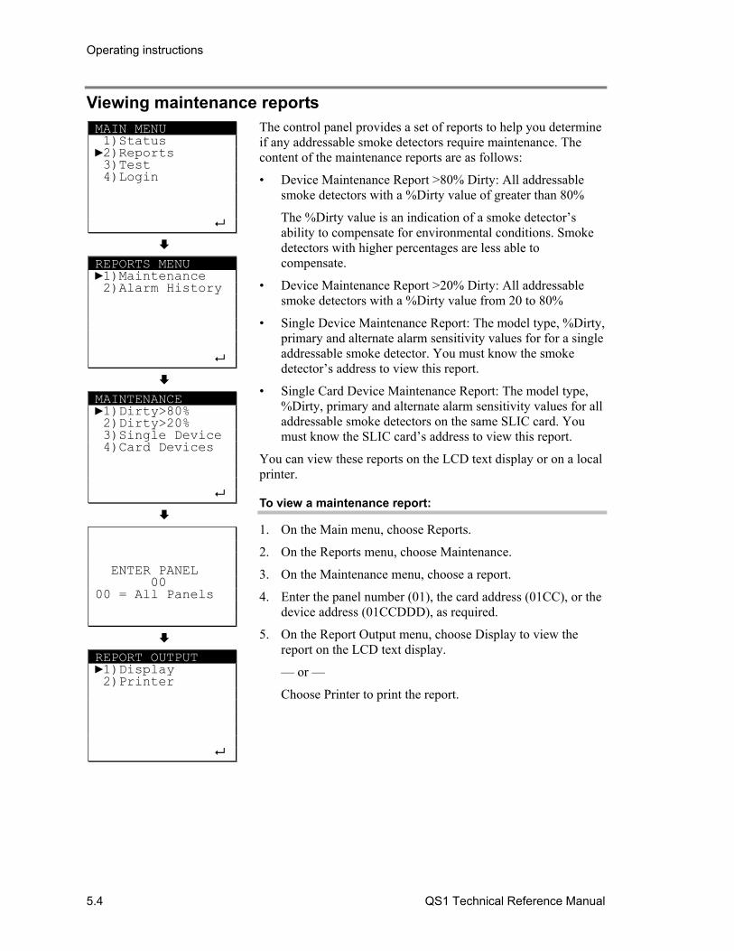
Operating instructions
5.4 QS1 Technical Reference Manual
Viewing maintenance reports The control panel provides a set of reports to help you determine if any addressable smoke detectors require maintenance. The content of the maintenance reports are as follows:
• Device Maintenance Report >80% Dirty: All addressable smoke detectors with a %Dirty value of greater than 80%
The %Dirty value is an indication of a smoke detector’s ability to compensate for environmental conditions. Smoke detectors with higher percentages are less able to compensate.
• Device Maintenance Report >20% Dirty: All addressable smoke detectors with a %Dirty value from 20 to 80%
• Single Device Maintenance Report: The model type, %Dirty, primary and alternate alarm sensitivity values for for a single addressable smoke detector. You must know the smoke detector’s address to view this report.
• Single Card Device Maintenance Report: The model type, %Dirty, primary and alternate alarm sensitivity values for all addressable smoke detectors on the same SLIC card. You must know the SLIC card’s address to view this report.
You can view these reports on the LCD text display or on a local printer.
To view a maintenance report:
1. On the Main menu, choose Reports.
2. On the Reports menu, choose Maintenance.
3. On the Maintenance menu, choose a report.
4. Enter the panel number (01), the card address (01CC), or the device address (01CCDDD), as required.
5. On the Report Output menu, choose Display to view the report on the LCD text display.
— or —
Choose Printer to print the report.
MAIN MENU 1)Status 2)Reports 3)Test 4)Login
REPORTS MENU 1)Maintenance 2)Alarm History
MAINTENANCE 1)Dirty>80% 2)Dirty>20% 3)Single Device 4)Card Devices
ENTER PANEL 00 00 = All Panels
REPORT OUTPUT 1)Display 2)Printer
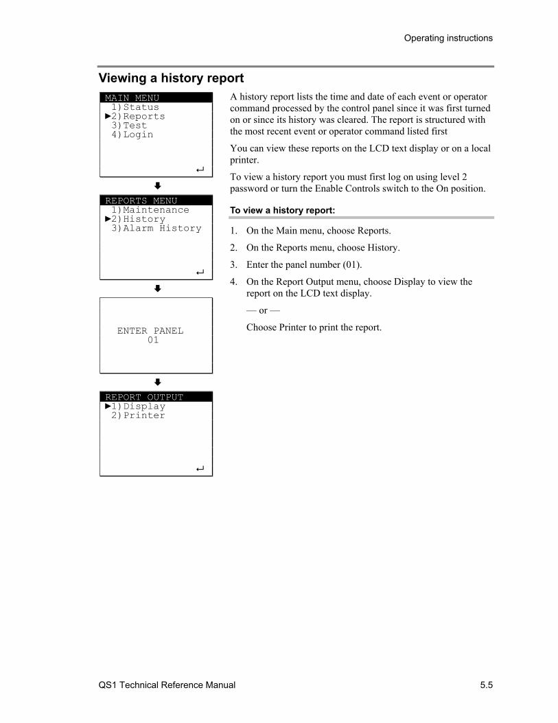
Operating instructions
QS1 Technical Reference Manual 5.5
Viewing a history report A history report lists the time and date of each event or operator command processed by the control panel since it was first turned on or since its history was cleared. The report is structured with the most recent event or operator command listed first
You can view these reports on the LCD text display or on a local printer.
To view a history report you must first log on using level 2 password or turn the Enable Controls switch to the On position.
To view a history report:
1. On the Main menu, choose Reports.
2. On the Reports menu, choose History.
3. Enter the panel number (01).
4. On the Report Output menu, choose Display to view the report on the LCD text display.
— or —
Choose Printer to print the report.
MAIN MENU 1)Status 2)Reports 3)Test 4)Login
REPORTS MENU 1)Maintenance 2)History 3)Alarm History
ENTER PANEL 01
REPORT OUTPUT 1)Display 2)Printer

Operating instructions
5.6 QS1 Technical Reference Manual
Viewing alarm history reports The alarm history report lists how many times the control panel has gone into alarm since the last time the alarm history counter was cleared.
To view an alarm history report:
1. On the Main menu, choose Reports.
2. On the Reports menu, choose Alarm History.
MAIN MENU 1)Status 2)Reports 3)Test 4)Login
REPORTS MENU 1)Maintenance 2)Alarm History
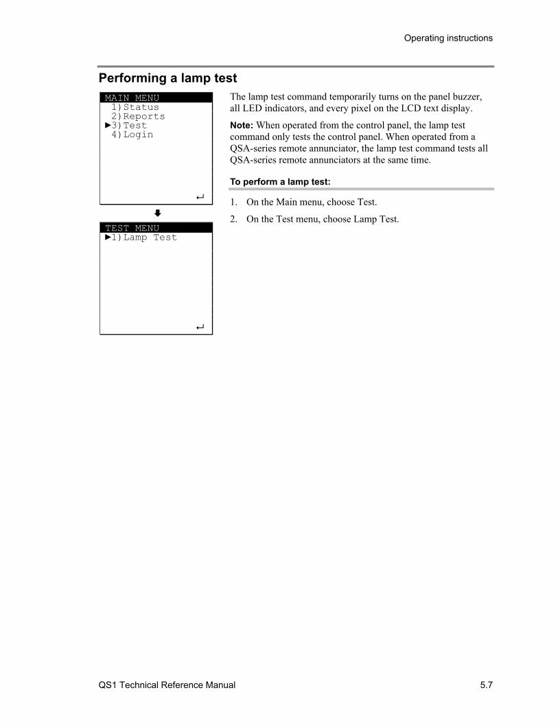
Operating instructions
QS1 Technical Reference Manual 5.7
Performing a lamp test The lamp test command temporarily turns on the panel buzzer, all LED indicators, and every pixel on the LCD text display.
Note: When operated from the control panel, the lamp test command only tests the control panel. When operated from a QSA-series remote annunciator, the lamp test command tests all QSA-series remote annunciators at the same time.
To perform a lamp test:
1. On the Main menu, choose Test.
2. On the Test menu, choose Lamp Test.
MAIN MENU 1)Status 2)Reports 3)Test 4)Login
TEST MENU 1)Lamp Test

Operating instructions
5.8 QS1 Technical Reference Manual
Silencing the panel buzzer The panel buzzer sounds whenever an event message is received at the control panel. Pressing the Panel Silence button:
• Silences the panel buzzer on the control panel and acknowledges all current event messages
• Silences the panel buzzer on all remote annunciators
To silence the panel buzzer:
1. Press Panel Silence.
2. Enter the level 2 password.
Notes
• Depending on your project settings, the panel buzzer may not re-sound or may re-sound automatically after 1, 2, 3, 6, 12, or 24 hours, if no new event message is received at the control panel
• Depending on your project settings, the panel buzzer may emit a short sound periodically to indicate that the system is not normal and the panel has been silenced
• The control panel will not silence the panel buzzer on remote annunciators that are not communicating. To silence the remote annunciator’s panel buzzer after the trouble has been restored you must press the control panel’s Panel Silence button again or press the panel silence button on the remote annunciator.
Operating instructions
QS1 Technical Reference Manual 5.9
Resetting the fire alarm system Pressing the System Reset button restores the fire alarm system to its normal state provided there are no active devices or circuits at the end of the reset cycle. If any devices or circuits are still active, audible notification appliances, if silenced, will re-sound and the panel buzzer, if silenced, will re-sound.
WARNING: The protected premises may be occupied. Do not silence alarm signals or reset the control panel unless you are authorized to do so and only after all occupants have been evacuated.
To reset the fire alarm system:
1. Press Reset.
2. Enter the level 2 password.
Operating instructions
5.10 QS1 Technical Reference Manual
Silencing alarm signals Pressing the Alarm Silence button silences all audible and common alarm device types, and if configured, visible device types.
Pressing Alarm Silence does not silence the device types described above under the following conditions:
• When a waterflow device type is active and the system’s Allow Waterflow Silence option is not enabled
• When the system is configured to delay the silencing of alarm signals, in which case the Alarm Silence button may not be operational for up to five minutes after the initial fire alarm event
Silenced outputs automatically re-sound when:
• The Alarm Silence button is pressed a second time
• Another alarm input device type is activated
• A subsequent device in an active zone is activated and the system is configured to allow zone re-sounding.
WARNING: The protected premises may be occupied. Do not silence alarm signals or reset the control panel unless you are authorized to do so and only after all occupants have been evacuated.
To silence alarm signals:
1. Press Alarm Silence.
2. Enter the level 2 password.
Operating instructions
QS1 Technical Reference Manual 5.11
Sounding an alarm Pressing the Drill button activates all audible and common alarm devices types, and if configured, visible device types. Pressing the Drill button a second time returns these outputs to their normal condition.
To sound an alarm:
1. Press Drill.
2. Press Enter to confirm that you want to sound all alarms.
3. Enter the level 2 password.
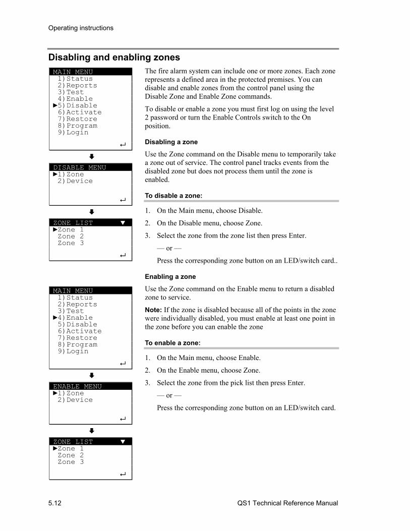
Operating instructions
5.12 QS1 Technical Reference Manual
Disabling and enabling zones The fire alarm system can include one or more zones. Each zone represents a defined area in the protected premises. You can disable and enable zones from the control panel using the Disable Zone and Enable Zone commands.
To disable or enable a zone you must first log on using the level 2 password or turn the Enable Controls switch to the On position.
Disabling a zone
Use the Zone command on the Disable menu to temporarily take a zone out of service. The control panel tracks events from the disabled zone but does not process them until the zone is enabled.
To disable a zone:
1. On the Main menu, choose Disable.
2. On the Disable menu, choose Zone.
3. Select the zone from the zone list then press Enter.
— or —
Press the corresponding zone button on an LED/switch card..
Enabling a zone
Use the Zone command on the Enable menu to return a disabled zone to service.
Note: If the zone is disabled because all of the points in the zone were individually disabled, you must enable at least one point in the zone before you can enable the zone
To enable a zone:
1. On the Main menu, choose Enable.
2. On the Enable menu, choose Zone.
3. Select the zone from the pick list then press Enter.
— or —
Press the corresponding zone button on an LED/switch card.
MAIN MENU 1)Status 2)Reports 3)Test 4)Enable 5)Disable 6)Activate 7)Restore 8)Program 9)Login
DISABLE MENU 1)Zone 2)Device
ZONE LIST Zone 1 Zone 2 Zone 3
MAIN MENU 1)Status 2)Reports 3)Test 4)Enable 5)Disable 6)Activate 7)Restore 8)Program 9)Login
ENABLE MENU 1)Zone 2)Device
ZONE LIST Zone 1 Zone 2 Zone 3
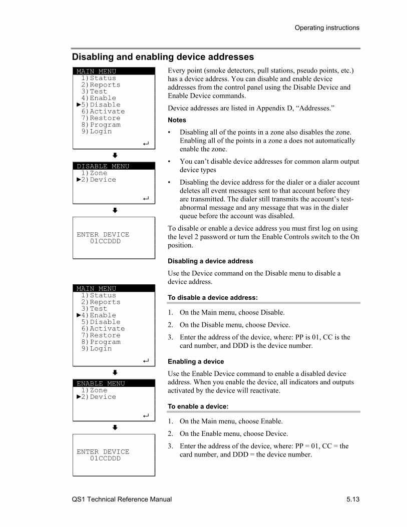
Operating instructions
QS1 Technical Reference Manual 5.13
Disabling and enabling device addresses Every point (smoke detectors, pull stations, pseudo points, etc.) has a device address. You can disable and enable device addresses from the control panel using the Disable Device and Enable Device commands.
Device addresses are listed in Appendix D, “Addresses.”
Notes
• Disabling all of the points in a zone also disables the zone. Enabling all of the points in a zone a does not automatically enable the zone.
• You can’t disable device addresses for common alarm output device types
• Disabling the device address for the dialer or a dialer account deletes all event messages sent to that account before they are transmitted. The dialer still transmits the account’s test-abnormal message and any message that was in the dialer queue before the account was disabled.
To disable or enable a device address you must first log on using the level 2 password or turn the Enable Controls switch to the On position.
Disabling a device address
Use the Device command on the Disable menu to disable a device address.
To disable a device address:
1. On the Main menu, choose Disable.
2. On the Disable menu, choose Device.
3. Enter the address of the device, where: PP is 01, CC is the card number, and DDD is the device number.
Enabling a device
Use the Enable Device command to enable a disabled device address. When you enable the device, all indicators and outputs activated by the device will reactivate.
To enable a device:
1. On the Main menu, choose Enable.
2. On the Enable menu, choose Device.
3. Enter the address of the device, where: PP = 01, CC = the card number, and DDD = the device number.
MAIN MENU 1)Status 2)Reports 3)Test 4)Enable 5)Disable 6)Activate 7)Restore 8)Program 9)Login
DISABLE MENU 1)Zone 2)Device
ENTER DEVICE 01CCDDD
MAIN MENU 1)Status 2)Reports 3)Test 4)Enable 5)Disable 6)Activate 7)Restore 8)Program 9)Login
ENABLE MENU 1)Zone 2)Device
ENTER DEVICE 01CCDDD

Operating instructions
5.14 QS1 Technical Reference Manual
Switching detector alarm sensitivity Intelligent addressable detectors are configured with two alarm sensitivity thresholds. Typically, the primary alarm sensitivity threshold is used for daytime operation. The alternate alarm sensitivity threshold is used for nighttime and weekend operation.
Typically, a time control is used to automatically switch alarm sensitivity thresholds. You can manually switch alarm sensitivity thresholds using the Alternate Sensitivity and Primary Sensitivity commands.
To switch alarm sensitivity thresholds manually you must first log on using the level 2 password or turn the Enable Controls switch to the On position.
The default setting for both primary and alternate alarm sensitivity is “Low.”
Switching from primary to alternate alarm sensitivity
Use the Alt Sens (alternate sensitivity) command on the Activate menu to switch smoke detector alarm sensitivity thresholds from their primary threshold value to their alternate threshold value.
To switch from primary to alternate sensitivity:
1. On the Main menu, choose Activate.
2. On the Activate menu, choose Alt Sens.
Switching from alternate to primary alarm sensitivity
Use the Prm Sens (primary sensitivity) command on the Restore menu to switch smoke detector alarm sensitivity thresholds from their alternate threshold value to their primary threshold value.
To switch from alternate to primary sensitivity:
1. On the Main menu, choose Restore.
2. On the Restore menu, choose Prm Sens.
MAIN MENU 1)Status 2)Reports 3)Test 4)Enable 5)Disable 6)Activate 7)Restore 8)Program 9)Login
ACTIVATE MENU 1)Alt Sens 2)Alt Msg Route
MAIN MENU 1)Status 2)Reports 3)Test 4)Enable 5)Disable 6)Activate 7)Restore 8)Program 9)Login
RESTORE MENU 1)Prm Sens 2)Prm Msg Route
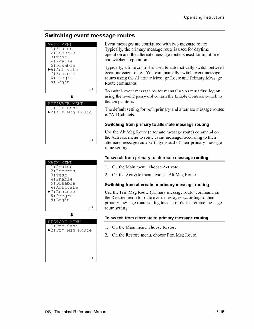
Operating instructions
QS1 Technical Reference Manual 5.15
Switching event message routes Event messages are configured with two message routes. Typically, the primary message route is used for daytime operation and the alternate message route is used for nighttime and weekend operation.
Typically, a time control is used to automatically switch between event message routes. You can manually switch event message routes using the Alternate Message Route and Primary Message Route commands.
To switch event message routes manually you must first log on using the level 2 password or turn the Enable Controls switch to the On position.
The default setting for both primary and alternate message routes is “All Cabinets.”
Switching from primary to alternate message routing
Use the Alt Msg Route (alternate message route) command on the Activate menu to route event messages according to their alternate message route setting instead of their primary message route setting.
To switch from primary to alternate message routing:
1. On the Main menu, choose Activate.
2. On the Activate menu, choose Alt Msg Route.
Switching from alternate to primary message routing
Use the Prm Msg Route (primary message route) command on the Restore menu to route event messages according to their primary message route setting instead of their alternate message route setting.
To switch from alternate to primary message routing:
1. On the Main menu, choose Restore.
2. On the Restore menu, choose Prm Msg Route.
MAIN MENU 1)Status 2)Reports 3)Test 4)Enable 5)Disable 6)Activate 7)Restore 8)Program 9)Login
ACTIVATE MENU 1)Alt Sens 2)Alt Msg Route
MAIN MENU 1)Status 2)Reports 3)Test 4)Enable 5)Disable 6)Activate 7)Restore 8)Program 9)Login
RESTORE MENU 1)Prm Sens 2)Prm Msg Route

Operating instructions
5.16 QS1 Technical Reference Manual
Changing the level 1 password Use the Edit Password command on the Program menu to change the password setting for using level 1 command menus.
To switch alarm sensitivity thresholds manually you must first log on using the level 2 password or turn the Enable Controls switch to the On position.
The default level 1 password is 1111.
To change the level 1 password:
1. On the Main menu, choose Program.
2. On the Program menu, choose Edit Password.
3. On the Password menu, choose Level 1.
4. Enter the new password.
MAIN MENU 1)Status 2)Reports 3)Test 4)Enable 5)Disable 6)Activate 7)Restore 8)Program 9)Login
PROGRAM MENU 1)Edit Password
PASSWORD MENU 1)Level 1
ENTER PASSWORD XXXX
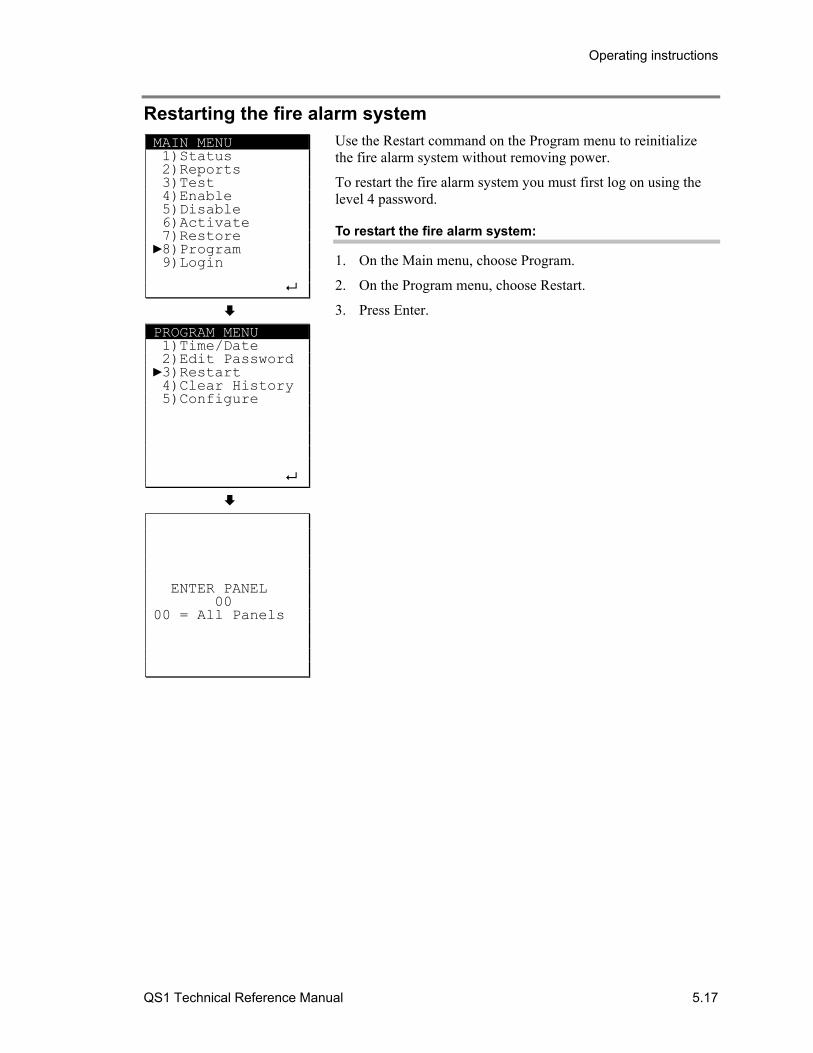
Operating instructions
QS1 Technical Reference Manual 5.17
Restarting the fire alarm system Use the Restart command on the Program menu to reinitialize the fire alarm system without removing power.
To restart the fire alarm system you must first log on using the level 4 password.
To restart the fire alarm system:
1. On the Main menu, choose Program.
2. On the Program menu, choose Restart.
3. Press Enter.
MAIN MENU 1)Status 2)Reports 3)Test 4)Enable 5)Disable 6)Activate 7)Restore 8)Program 9)Login
PROGRAM MENU 1)Time/Date 2)Edit Password 3)Restart 4)Clear History 5)Configure
ENTER PANEL 00 00 = All Panels

Operating instructions
5.18 QS1 Technical Reference Manual
QS1 Technical Reference Manual 6.1
Chapter 6 Installation
Summary
This chapter provides instructions for installing the fire alarm system. It is intended for trained installers who are familiar with all applicable codes and regulations.
Content
Installation overview • 6.2 Mounting the control panel backbox • 6.4 Pulling cables into the backbox • 6.6 Installing panel components • 6.8 Installing the PS6 card • 6.9 Installing the front panel • 6.10 Connecting mains AC • 6.13 Installing standby batteries • 6.14 Installing a QSA series remote annunciator • 6.15
Mounting the backbox • 6.15 Pulling cables into the backbox • 6.18 Installing the RAI card • 6.18 Installing the front panel • 6.18 RAI card wiring • 6.20
System startup procedure • 6.22 Connecting peripheral devices • 6.27
Connecting a computer • 6.27 Connecting a serial printer • 6.27
Connecting auxiliary/booster power supplies • 6.29 Installation requirements for UL 864 signal
synchronization • 6.31

Installation
6.2 QS1 Technical Reference Manual
Installation overview This topic provides a descriptive overview of how to install the fire alarm system. Please read this topic in its entirety before proceeding.
The fire alarm system must be installed in accordance with the manufacturer’s instructions, the local authority having jurisdiction (AHJ), and all local, regional, and national electrical and building codes.
Step 1 - Unpack the equipment: Before you begin, you should unpack the equipment to make sure you have everything you need and that it is has not been damaged.
Step 2 - Mount the control panel backbox: Mount the control panel backbox first. When mounting the control panel backbox, please keep in mind the following:
• Make sure the installation location is free from construction dust and debris, and immune to extreme temperature ranges and humidity
• Allow for enough floor and wall space so the panel can be installed and serviced without any obstructions
• Use fasteners that can support the full weight of the cabinet, including the standby batteries
• Tighten fasteners firmly to prevent the cabinet from vibrating
For more information, see “Mounting the control panel backbox” later in this chapter.
Step 3 - Pull the cables into the backbox: Pull all of the cables into the backbox and tag them for easy identification. Do not worry about dressing the cables until after the panel components are installed. For more information, see “Pulling cables into the backbox” later in this chapter.
Step 4 - Install the panel components: Install the panel components only after the threat of construction damage and vandalism has passed. All panel components are sensitive to ESD (electrostatic discharge). To prevent ESD damage:
• Keep panel components in their protective antistatic packaging at all times. Remove only for inspection or installation.
• Ground yourself with an approved static-protective wrist strap when handling panel components
• Do not touch any component leads or connector pins when installing panel components
Installation
QS1 Technical Reference Manual 6.3
For more information, see “Installing panel components” later in this chapter. Additional installation information is provided in Chapter 3, “Panel components,” and in the installation sheets that are shipped with each piece of equipment.
Step 5 - Connect mains AC: Connect mains AC power after all the panel components have been installed and wired. Do not energize the panel until you are ready to commission the system. For more information, see “Connecting mains AC” later in this chapter.
Step 6 - Install the standby batteries: Typically, standby batteries are placed in the cabinet but not connected until after the system has been tested in order to preserve battery life. Do not connect the battery until the panel is energized. For more information, see “Installing standby batteries” later in this chapter.
Step 7 - Install remote annunciators: If the system includes remote annunciators, install them before commissioning the system. For more information, see “Installing QSA series remote annunciators” later in this chapter.
Step 8 - Commission the system: Commissioning the system involves energizing the system, programming the system, and then testing the system. You should commission the system only after a complete visual inspection of the control panel and other equipment. Check for any damage that may have occurred during the installation. For more information, see “Commissioning the system” later in this chapter.
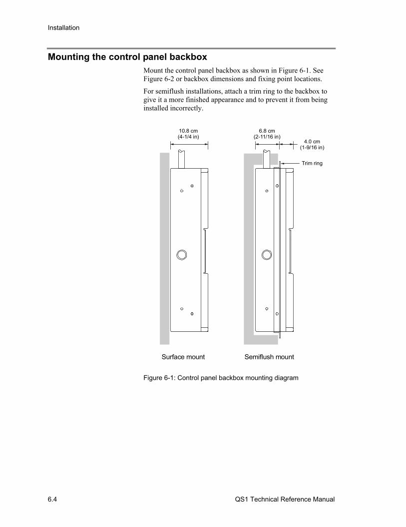
Installation
6.4 QS1 Technical Reference Manual
Mounting the control panel backbox Mount the control panel backbox as shown in Figure 6-1. See Figure 6-2 or backbox dimensions and fixing point locations.
For semiflush installations, attach a trim ring to the backbox to give it a more finished appearance and to prevent it from being installed incorrectly.
Surface mount Semiflush mount
10.8 cm(4-1/4 in)
6.8 cm(2-11/16 in)
4.0 cm(1-9/16 in)
Trim ring
Figure 6-1: Control panel backbox mounting diagram

Installation
QS1 Technical Reference Manual 6.5
18 in(45.7 cm)
1.3 in (3.2 cm)
3.1 in (7.8 cm)
4.9 in(12.4 cm)
7.1 in (18.1 cm)
9.4 in (23.8 cm)
4.2 in(10.6 cm)
1.3 in(3.2 cm)
4.0 in(10.2 cm)
7.8 in(19.7 cm)
Fixing points(semiflush mount)
Fixing points(semiflush mount)
12.2 in(31.1 cm)
11.2 in (28.4 cm)
13 in (33.0 cm)
4.0 in(10.2 cm)
Figure 6-2: Backbox dimensions for a QS1-1-(G/R)-1
Installation
6.6 QS1 Technical Reference Manual
Pulling cables into the backbox Pull high voltage mains power cables into the backbox through the knockout closest to the terminal block as shown Figure 6-3. Pull all low voltage data cables into the backbox through the remaining knockouts. When pulling cables into the backbox, keep in mind the following:
• Keep low voltage cables within the shaded area. Keep high voltage cables within the unshaded area.
• Do not run cables through the knockouts at the bottom of the backbox if batteries are to be installed in the cabinet
• Make sure to remove any debris and any metal filings after pulling the cables into the backbox
Note: There are a sufficient number of knockouts to pull cables into the backbox in a neat and orderly manner without having to punch additional holes.
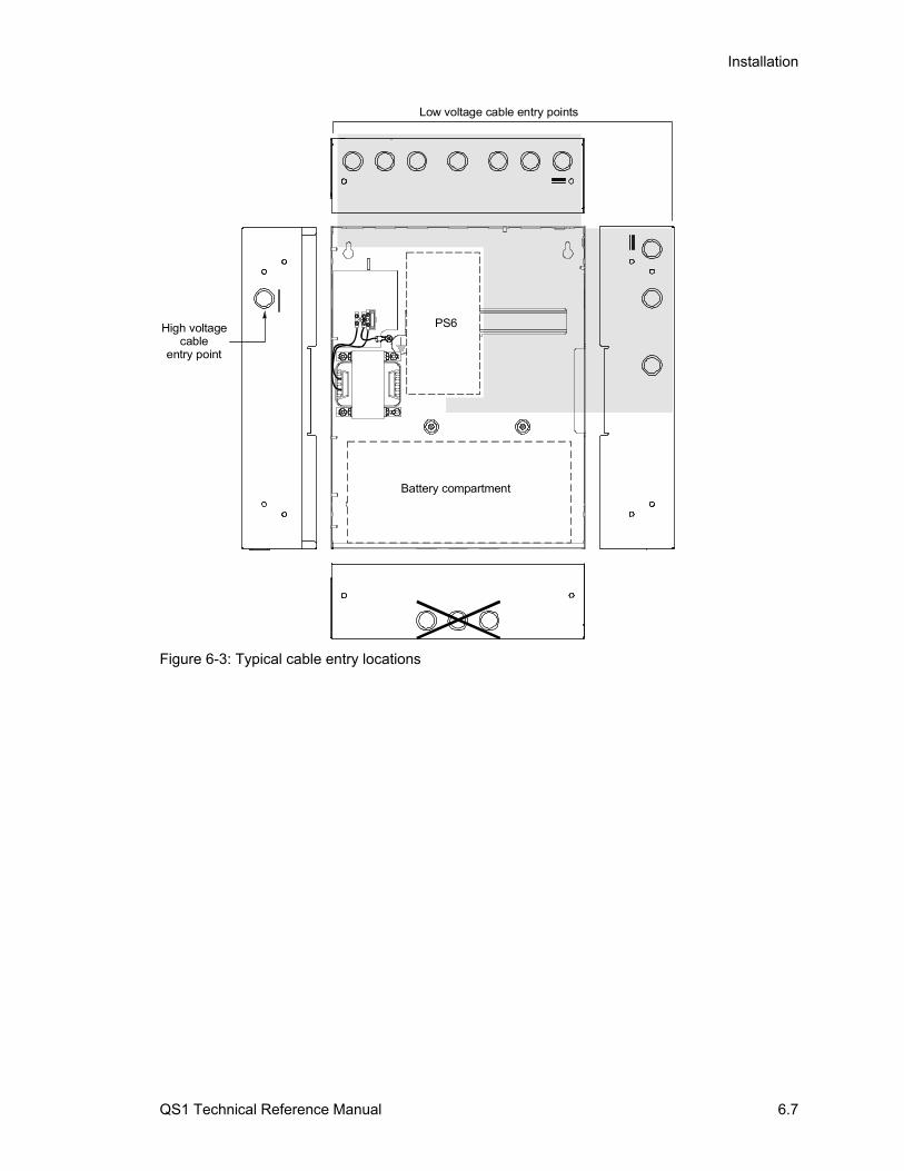
Installation
QS1 Technical Reference Manual 6.7
Battery compartment
PS6
Low voltage cable entry points
High voltagecable
entry point
Figure 6-3: Typical cable entry locations

Installation
6.8 QS1 Technical Reference Manual
Installing panel components Figure 6-4 shows the recommended cabinet layout for installing panel components. Install panel components in the following order:
1. Install the PS6 card. For more information, see “Installing the PS6 card” later in this chapter.
2. Install the front panel. For more information, see “Installing the front panel” later in this chapter.
3. Install the RS-485 card, if used, next to the PS6 card.
4. Install all remaining option cards and set their card addresses.
Caution: Do not install any panel components while the control panel is energized.
Tip: Wait until the possibility of construction damage or vandalism has passed before installing the panel components.
SLIC card or RS-485 card SLIC card (if RS-485 is installed),DLD card, or ZR8 card
Battery compartment
Figure 6-4: Cabinet layout diagram
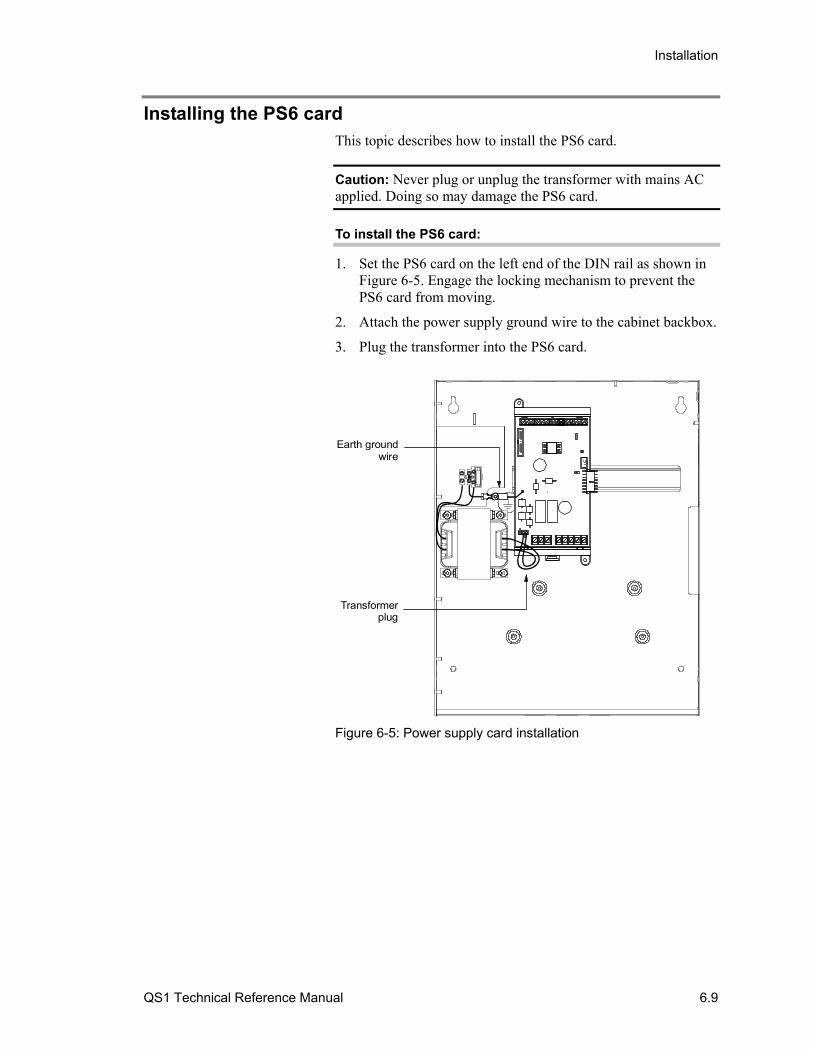
Installation
QS1 Technical Reference Manual 6.9
Installing the PS6 card This topic describes how to install the PS6 card.
Caution: Never plug or unplug the transformer with mains AC applied. Doing so may damage the PS6 card.
To install the PS6 card:
1. Set the PS6 card on the left end of the DIN rail as shown in Figure 6-5. Engage the locking mechanism to prevent the PS6 card from moving.
2. Attach the power supply ground wire to the cabinet backbox.
3. Plug the transformer into the PS6 card.
Earth groundwire
Transformerplug
Figure 6-5: Power supply card installation

Installation
6.10 QS1 Technical Reference Manual
Installing the front panel This topic describes how to install the front panel. The front panel consists of the cabinet door, the CPU/Display Unit, and LED/switch cards.
Step 1: Attach the cabinet door to the backbox
Attach the cabinet door to the backbox then connect the ground strap between the backbox and the cabinet door. See Figure 6-6.
Ground strap
#6 k-nut(4X)
#8 k-nut(2X)
Figure 6-6: Cabinet door assembly
Step 2: Attach the CPU/Display Unit and LED/switch cards to the cabinet door
Set the LED/switch cards inside the CPU/Display Unit then attach the CPU/Display Unit to the cabinet door as shown in Figure 6-7.
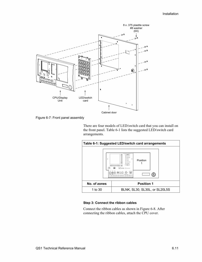
Installation
QS1 Technical Reference Manual 6.11
8 x .375 plastite screw#8 washer
(6X)
CPU/DisplayUnit
LED/switchcard
Cabinet door
Figure 6-7: Front panel assembly
There are four models of LED/switch card that you can install on the front panel. Table 6-1 lists the suggested LED/switch card arrangements.
Table 6-1: Suggested LED/switch card arrangements
1 2 3 4 6 7 8 9 05
ALARM
Supervisory
CPU Fault
Ground Fault
Trouble
Disable/Test
Monitor
Power
PRESS ZONE FOR INFORMATION
SystemReset
AlarmSilence
Help Status
Panel Silenced
Off
On
Enable Controls
MENU Del Enter
Panel Silence/Acknowledged
Drill
Position1
No. of zones Position 1
1 to 30 BLNK, SL30, SL30L, or SL20L5S
Step 3: Connect the ribbon cables
Connect the ribbon cables as shown in Figure 6-8. After connecting the ribbon cables, attach the CPU cover.

Installation
6.12 QS1 Technical Reference Manual
7140015-027140013
Attach key switchground wire to nearestpoint on cabinet door
Figure 6-8: Front panel ribbon cable connections
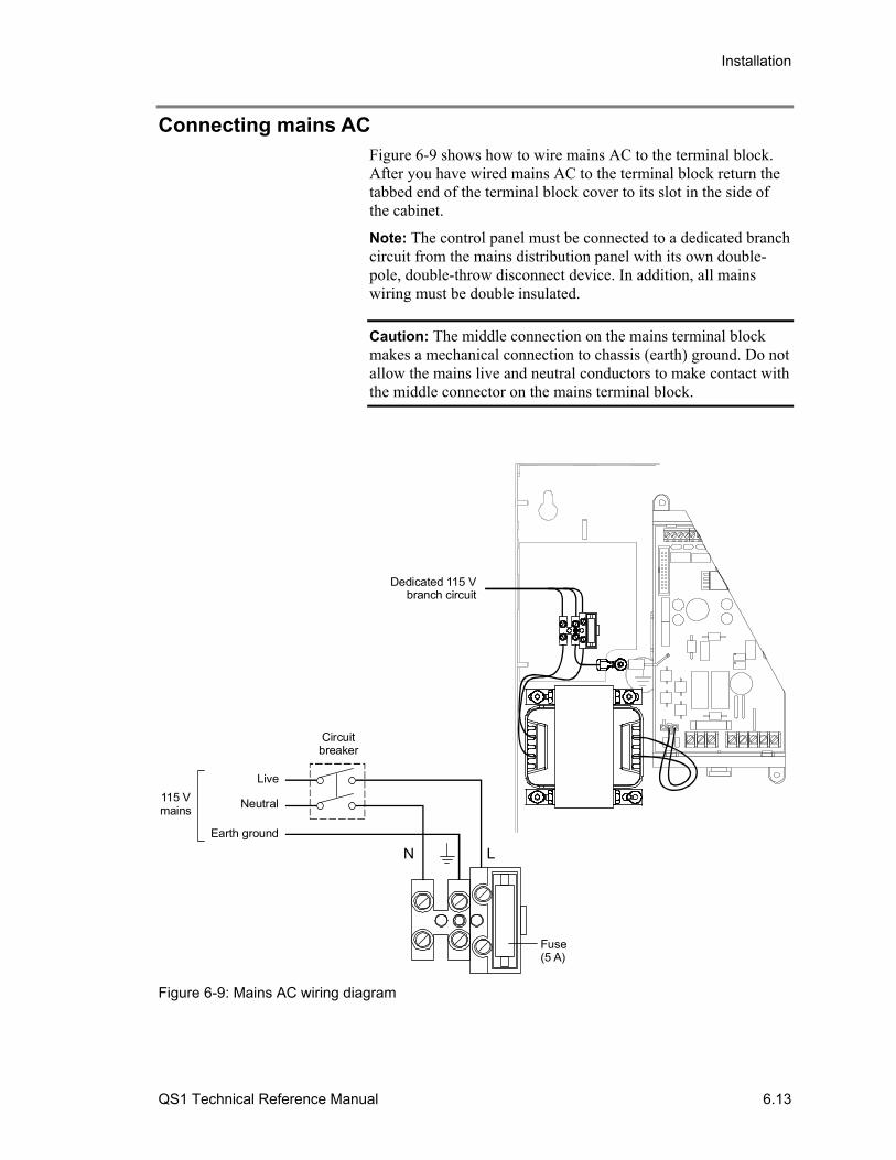
Installation
QS1 Technical Reference Manual 6.13
Connecting mains AC Figure 6-9 shows how to wire mains AC to the terminal block. After you have wired mains AC to the terminal block return the tabbed end of the terminal block cover to its slot in the side of the cabinet.
Note: The control panel must be connected to a dedicated branch circuit from the mains distribution panel with its own double-pole, double-throw disconnect device. In addition, all mains wiring must be double insulated.
Caution: The middle connection on the mains terminal block makes a mechanical connection to chassis (earth) ground. Do not allow the mains live and neutral conductors to make contact with the middle connector on the mains terminal block.
Dedicated 115 Vbranch circuit
Neutral
Live
Earth ground
115 Vmains
Fuse(5 A)
LN
Circuitbreaker
Figure 6-9: Mains AC wiring diagram
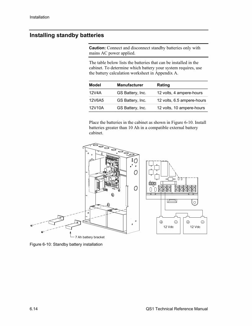
Installation
6.14 QS1 Technical Reference Manual
Installing standby batteries
Caution: Connect and disconnect standby batteries only with mains AC power applied.
The table below lists the batteries that can be installed in the cabinet. To determine which battery your system requires, use the battery calculation worksheet in Appendix A.
Model Manufacturer Rating
12V4A GS Battery, Inc. 12 volts, 4 ampere-hours
12V6A5 GS Battery, Inc. 12 volts, 6.5 ampere-hours
12V10A GS Battery, Inc. 12 volts, 10 ampere-hours
Place the batteries in the cabinet as shown in Figure 6-10. Install batteries greater than 10 Ah in a compatible external battery cabinet.
7 Ah battery bracket
12 Vdc12 Vdc
Figure 6-10: Standby battery installation
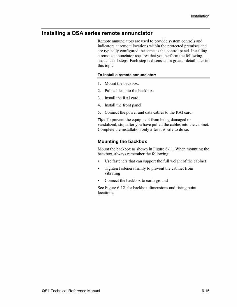
Installation
QS1 Technical Reference Manual 6.15
Installing a QSA series remote annunciator Remote annunciators are used to provide system controls and indicators at remote locations within the protected premises and are typically configured the same as the control panel. Installing a remote annunciator requires that you perform the following sequence of steps. Each step is discussed in greater detail later in this topic.
To install a remote annunciator:
1. Mount the backbox.
2. Pull cables into the backbox.
3. Install the RAI card.
4. Install the front panel.
5. Connect the power and data cables to the RAI card.
Tip: To prevent the equipment from being damaged or vandalized, stop after you have pulled the cables into the cabinet. Complete the installation only after it is safe to do so.
Mounting the backbox
Mount the backbox as shown in Figure 6-11. When mounting the backbox, always remember the following:
• Use fasteners that can support the full weight of the cabinet
• Tighten fasteners firmly to prevent the cabinet from vibrating
• Connect the backbox to earth ground
See Figure 6-12 for backbox dimensions and fixing point locations.
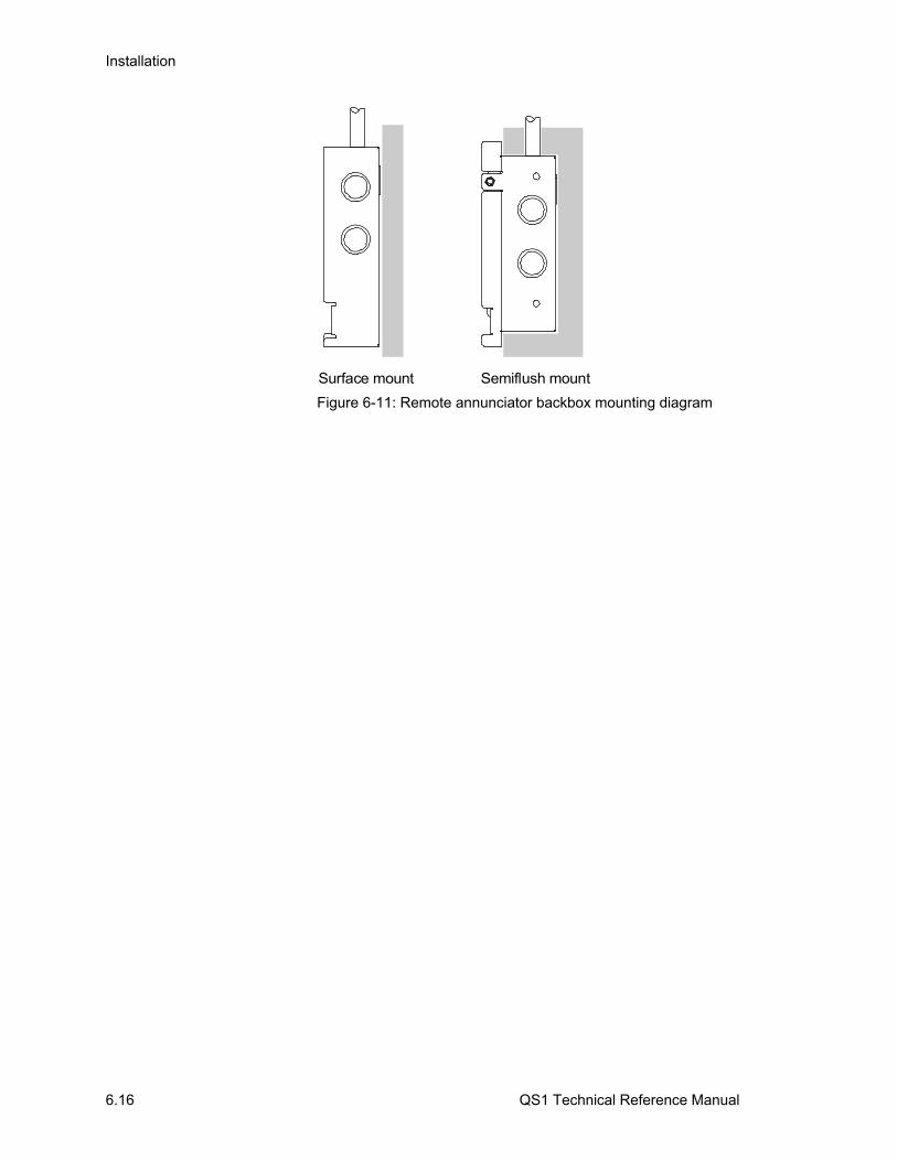
Installation
6.16 QS1 Technical Reference Manual
Surface mount Semiflush mount
Figure 6-11: Remote annunciator backbox mounting diagram
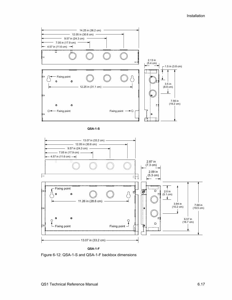
Installation
QS1 Technical Reference Manual 6.17
4.57 in (11.6 cm)
7.05 in (17.9 cm)
9.57 in (24.3 cm)
12.05 in (30.6 cm)
14.25 in (36.2 cm)
12.25 in (31.1 cm)
2.13 in(5.4 cm)
3.5 in(8.9 cm)
7.56 in(19.2 cm)
1.5 in (3.8 cm)
Fixing point Fixing point
Fixing point
13.07 in (33.2 cm)
2.09 in(5.3 cm)
2.87 in(7.3 cm)
13.07 in (33.2 cm)
2.0 in(5.1 cm)
3.94 in(10.2 cm)
6.57 in(16.7 cm)
7.68 in(19.5 cm)
Fixing point Fixing point
Fixing point
11.26 in (28.6 cm)
QSA-1-F
QSA-1-S
4.57 in (11.6 cm)
7.05 in (17.9 cm)
9.57 in (24.3 cm)
12.05 in (30.6 cm)
Figure 6-12: QSA-1-S and QSA-1-F backbox dimensions
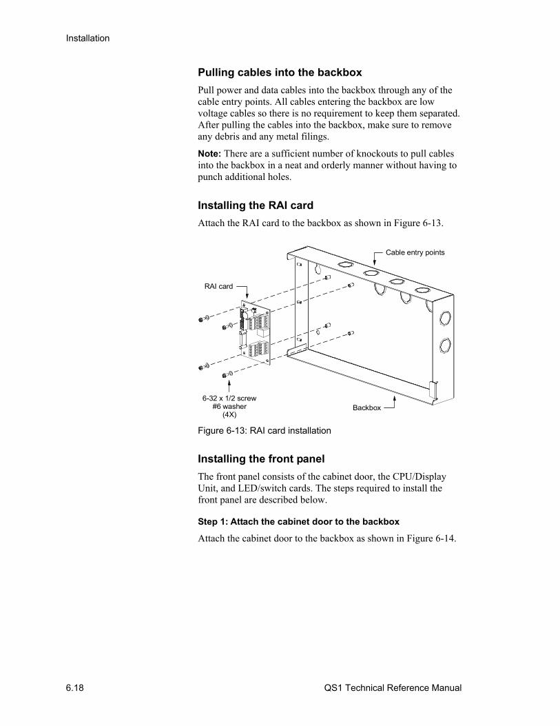
Installation
6.18 QS1 Technical Reference Manual
Pulling cables into the backbox
Pull power and data cables into the backbox through any of the cable entry points. All cables entering the backbox are low voltage cables so there is no requirement to keep them separated. After pulling the cables into the backbox, make sure to remove any debris and any metal filings.
Note: There are a sufficient number of knockouts to pull cables into the backbox in a neat and orderly manner without having to punch additional holes.
Installing the RAI card
Attach the RAI card to the backbox as shown in Figure 6-13.
Cable entry points
Backbox6-32 x 1/2 screw
#6 washer (4X)
RAI card
Figure 6-13: RAI card installation
Installing the front panel
The front panel consists of the cabinet door, the CPU/Display Unit, and LED/switch cards. The steps required to install the front panel are described below.
Step 1: Attach the cabinet door to the backbox
Attach the cabinet door to the backbox as shown in Figure 6-14.
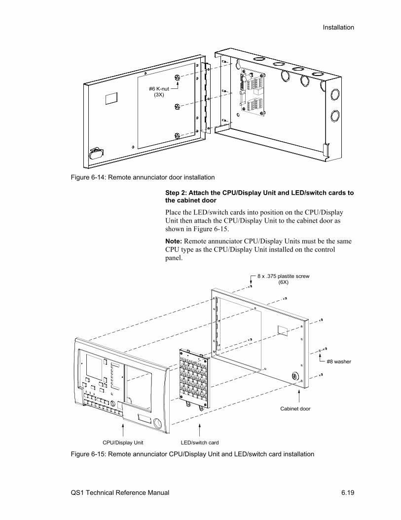
Installation
QS1 Technical Reference Manual 6.19
#6 K-nut(3X)
Figure 6-14: Remote annunciator door installation
Step 2: Attach the CPU/Display Unit and LED/switch cards to the cabinet door
Place the LED/switch cards into position on the CPU/Display Unit then attach the CPU/Display Unit to the cabinet door as shown in Figure 6-15.
Note: Remote annunciator CPU/Display Units must be the same CPU type as the CPU/Display Unit installed on the control panel.
8 x .375 plastite screw(6X)
CPU/Display Unit LED/switch card
Cabinet door
#8 washer
Figure 6-15: Remote annunciator CPU/Display Unit and LED/switch card installation

Installation
6.20 QS1 Technical Reference Manual
Attach the key switch ground strap to the cabinet door as shown in Figure 6-16.
#8 washerRing terminal
8 x .375 plastite screw
Key switch ground strap
CPU/DisplayUnit
Door
Figure 6-16: Key switch ground strap connection
Step 3: Connect the ribbon cables
Connect the ribbon cables as shown in Figure 6-17.
7140015-017140013
Figure 6-17: Remote annunciator ribbon cable connections
RAI card wiring
The remote annunciator requires a continuous 24 Vdc supply voltage and communicates with the control panel over the RS-485 riser.
Step 1: Connect the power cables
WARNING: Make sure the 24-volt supply is de-energized before connecting power cables to the RAI card.
Connect the power cables to the RAI card as shown in Figure 6-18.
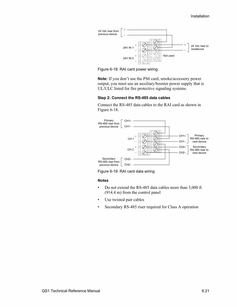
Installation
QS1 Technical Reference Manual 6.21
24 Vdc riser fromprevious device
24 Vdc riser tonextdevice24V IN 1
24V IN 2
Not used
Figure 6-18: RAI card power wiring
Note: If you don’t use the PS6 card, smoke/accessory power output, you must use an auxiliary/booster power supply that is UL/ULC listed for fire protective signaling systems.
Step 2: Connect the RS-485 data cables
Connect the RS-485 data cables to the RAI card as shown in Figure 6-18.
PrimaryRS-485 riser fromprevious device
CH1
CH1
CH 1
CH 2
CH1
CH1
CH2
CH2
CH2
CH2
SecondaryRS-485 riser fromprevious device
PrimaryRS-485 riser to
next device
SecondaryRS-485 riser to
next device
Figure 6-19: RAI card data wiring
Notes
• Do not extend the RS-485 data cables more than 3,000 ft (914.4 m) from the control panel
• Use twisted pair cables
• Secondary RS-485 riser required for Class A operation

Installation
6.22 QS1 Technical Reference Manual
System startup procedure This topic provides the factory recommended startup procedure for system consisting of a control panel with DLD card and a QSA-series or SRA-series remote annunciator.
You may vary this procedure depending on your installation requirements. For example, you may disregard the instructions for remote annunciators if you don’t have any or you may choose to connect the field wires one circuit at a time.
Note: This procedure requires that you have a laptop computer, the software configuration utility, and a PROGCABLE-1 download cable.
Summary
Here is a general summary of what you need to do to start the control panel:
1. Use the AutoLearn command to Initialize the control panel.
2. Use the Auto Loop command to initialize each SLIC card.
3. Retrieve (download) the CPU database from the control panel.
4. Make changes to the project. For example, add your event messages.
5. Save the project.
6. Send (upload) the project to the control panel.
After you finish you can start testing the system.
Before you begin
1. Install the PS6 card, the CPU/Display Unit, and all option cards except the DLD card. The DLD card will be installed later.
Make sure that each option card has a unique card address.
2. Connect the field wiring. Verify that all field wiring is free of opens, shorts, and ground faults (stray voltages) before terminating them at the panel.
3. Connect mains AC (primary power).
Do not connect the batteries (secondary power) or remote annunciators at this time. Typically, batteries are connected only after the system is operational.

Installation
QS1 Technical Reference Manual 6.23
Step 1: Initialize the control panel
1. Turn the control panel on.
The control panel will display a number of trouble events depending on your hardware configuration. If this is a new installation (no CPU database), the trouble queue will also display this event:
LCL TROUBLE No Database
2. Verify the CPU microcode is version 2.5 or later. If not, use the codeloader utility to upgrade the microcode to v2.5.
3. Run the AutoLearn command.
When prompted, enter the default values for the panel setup options (01, 01, Class B) then wait while the CPU database is updated.
4. Wait until the monitor queue is clear of all line initialization events then examine the trouble queue.
Verify the trouble queue contains the battery wiring or battery fault event and an unconfigured device event for each SLIC card installed.
Step 2: Initialize the SLIC cards
For each SLIC card:
1. Run the Auto Loop command.
The LCD displays the number of detector and module addresses found on the signaling line circuit.
2. If the number of addresses are correct, press Enter. If not, press Del. Remember, some modules use two addresses.
3. Wait while the CPU database is updated.
4. Exit the configuration menus, save the CPU database, then wait while the CPU database is updated.
5. Wait until the monitor queue is clear of all line initialization events then examine the trouble queue.
6. Verify the trouble queue contains only the battery wiring or battery fault event.
Step 3: Retrieve the CPU database from the control panel
1. Using the download cable, connect the laptop computer to the control panel’s RJ-12 jack.
2. Start the software configuration utility.

Installation
6.24 QS1 Technical Reference Manual
3. Retrieve the CPU database (sometimes called the actual database) from the control panel. Make sure the Retrieve System Data dialog box is set for the correct COM port before you click OK.
The time that it takes to copy the CPU database into the configuration utility varies with the size of the system. Be patient.
4. When the control panel has finished transferring the data, click OK to process the data.
5. Save the project as project_name Version 01.00.00. In the Description box, type “Initial project database”, or equivalent.
Step 4: Make changes to the panel’s programming
Using the configuration utility:
1. Add and configure the remote annunciator.
2. Add and configure the DLD card.
3. Change the configuration of any devices or circuits that do not use the default values.
4. Add event messages.
5. Create any zones, AND groups, time controls, service groups, etc.
6. Correlate inputs and outputs.
7. Save the project as project_name version 01.01.00 or other numbering scheme you choose to help you track your changes.
Step 4: Install the DLD card and remote annunciators
1. Turn the control panel off.
2. Install the DLD card. You may want to wait if the telephone equipment has not been installed yet.
3. Connect the remote annuciator wires to the control panel.
4. Turn the control panel on. If the remote annunciators are powered separately turn on their power.
Step 5: Send the CU database to the control panel
1. Connect the laptop computer to the control panel’s RJ-12 jack.
2. Verify the project’s CPU revision option is set for Versions 2.5 and Later.
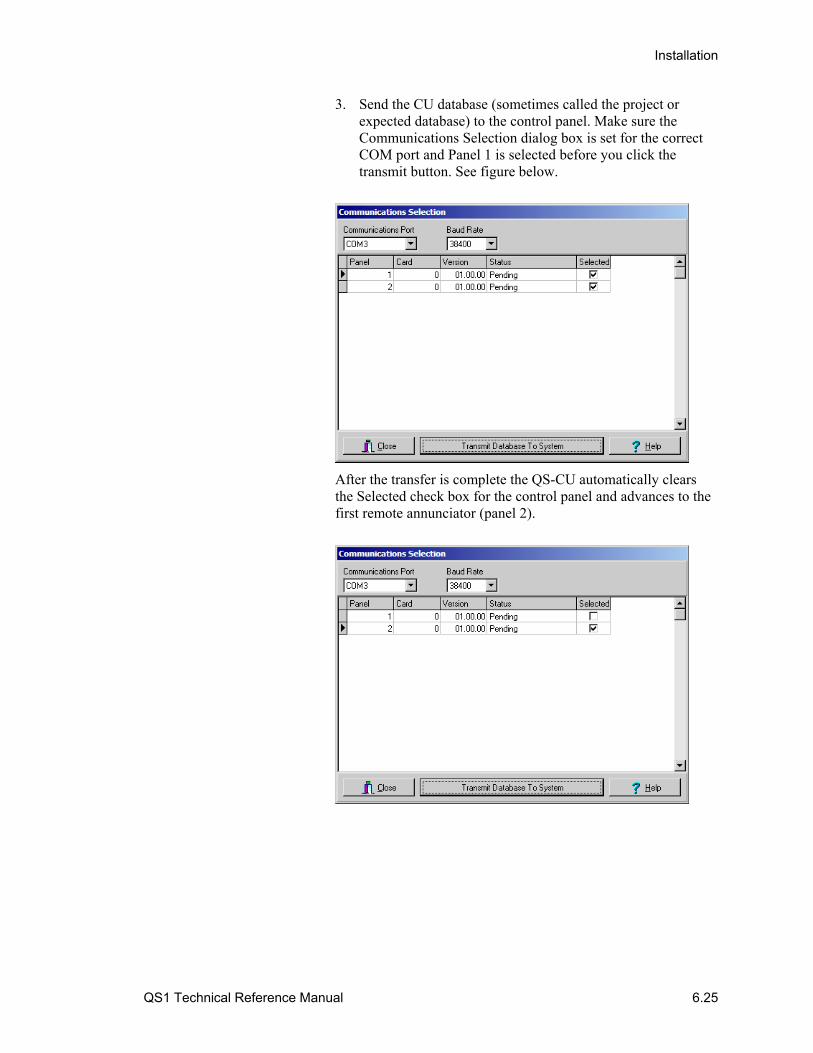
Installation
QS1 Technical Reference Manual 6.25
3. Send the CU database (sometimes called the project or expected database) to the control panel. Make sure the Communications Selection dialog box is set for the correct COM port and Panel 1 is selected before you click the transmit button. See figure below.
After the transfer is complete the QS-CU automatically clears the Selected check box for the control panel and advances to the first remote annunciator (panel 2).
Installation
6.26 QS1 Technical Reference Manual
Step 6: Send the CU database to the remote annunciators
1. Connect the laptop computer to the first remote annunciator (panel 2) then upload the project database.
If you get this error message…
The database built is not compatible with the system. Choose the correct version from the Project Configuration Form.
…you must use the codeloader utility to update the remote annunciator’s CPU microcode to the latest version before you can continue. The control panel and the remote annunciator’s CPU microcode versions must be the same.
2. Repeat for each remote annunciator installed. This is how you synchronize the databases. Do not use the control panel’s Save & Sync command to synchronize the databases.
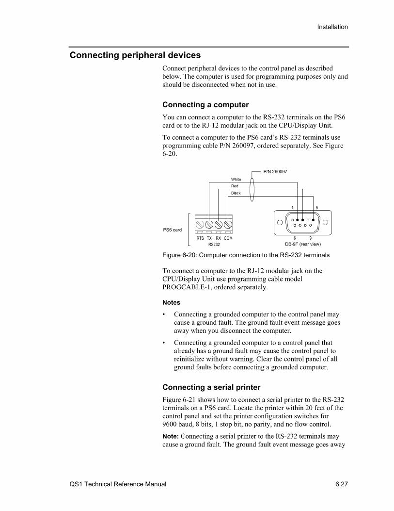
Installation
QS1 Technical Reference Manual 6.27
Connecting peripheral devices Connect peripheral devices to the control panel as described below. The computer is used for programming purposes only and should be disconnected when not in use.
Connecting a computer
You can connect a computer to the RS-232 terminals on the PS6 card or to the RJ-12 modular jack on the CPU/Display Unit.
To connect a computer to the PS6 card’s RS-232 terminals use programming cable P/N 260097, ordered separately. See Figure 6-20.
1 5
96RTS TX RX COMRS232
PS6 card
DB-9F (rear view)
P/N 260097
Black
Red
White
Figure 6-20: Computer connection to the RS-232 terminals
To connect a computer to the RJ-12 modular jack on the CPU/Display Unit use programming cable model PROGCABLE-1, ordered separately.
Notes
• Connecting a grounded computer to the control panel may cause a ground fault. The ground fault event message goes away when you disconnect the computer.
• Connecting a grounded computer to a control panel that already has a ground fault may cause the control panel to reinitialize without warning. Clear the control panel of all ground faults before connecting a grounded computer.
Connecting a serial printer
Figure 6-21 shows how to connect a serial printer to the RS-232 terminals on a PS6 card. Locate the printer within 20 feet of the control panel and set the printer configuration switches for 9600 baud, 8 bits, 1 stop bit, no parity, and no flow control.
Note: Connecting a serial printer to the RS-232 terminals may cause a ground fault. The ground fault event message goes away
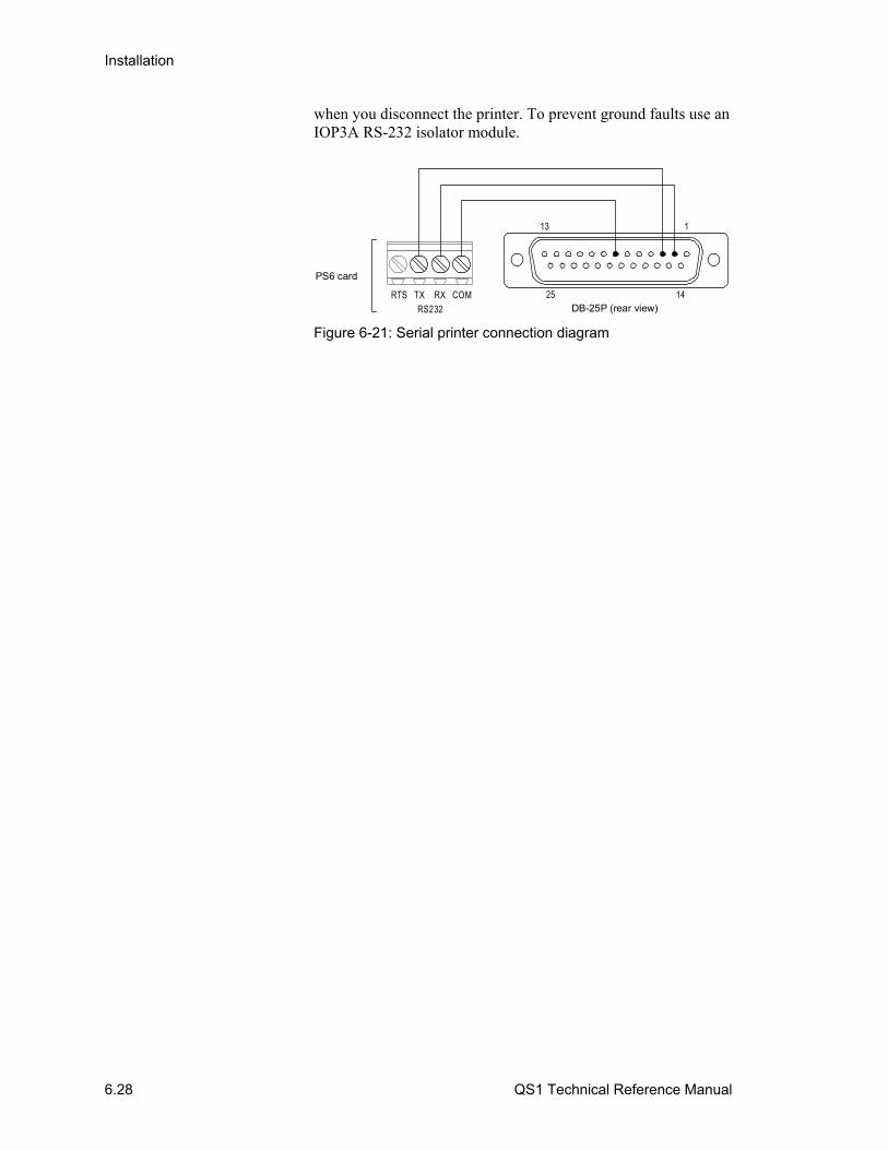
Installation
6.28 QS1 Technical Reference Manual
when you disconnect the printer. To prevent ground faults use an IOP3A RS-232 isolator module.
RTS TX RX COMRS232
PS6 card
DB-25P (rear view)
113
25 14
Figure 6-21: Serial printer connection diagram

Installation
QS1 Technical Reference Manual 6.29
Connecting auxiliary/booster power supplies Typically, auxiliary/booster power supplies are connected to the control panel using two notification appliance circuits (NACs) and an initiating device circuit.
Refer to Figure 6-22.
Note: UL requires that you monitor secondary power sources for loss of AC power. Upon loss of AC power, the control panel must provide an audible and visible trouble signal. In addition, remote station, central station, and proprietary-type protected premises units must transmit a trouble signal off-premises.

Installation
6.30 QS1 Technical Reference Manual
78
12
34
IN IN
Auxi
liary
/boo
ster
supp
ly [2
] CO
M
OU
T
CO
M
OU
T
Sens
e 1
Sens
e 2
NO
CO
M NC
20
0 m
AAU
X
NAC
1/A
UX
1
NAC
2/A
UX
2
NAC
3/A
UX
3
NAC
4/A
UX
4
Trou
ble
10 k
EOLRΩ
Activ
eNo
rmal
15 k
EO
LRΩ
Gen
esis
Tem
pora
lH
orn/
Stro
be
Gen
esis
Tem
pora
lH
orn/
Stro
be
Wire
the
sam
eas
NAC
1/A
UX
1
No
tes
1.
All
wir
ing
is s
up
erv
ise
d a
nd
po
we
r-lim
ited
un
less
oth
erw
ise
no
ted
[2]
Con
figu
re S
ens
e 1
and
Se
nse
2 o
pe
ratio
n f
or
Ge
ne
sis
Ma
ste
r m
od
e a
nd
NA
C
op
era
tion
for
Co
ntin
uo
us.
Se
e th
e a
uxi
liary
/bo
ost
er
supp
ly d
ocu
me
nta
tion
fo
r d
eta
ils.
4.7
kEO
LRΩ
Activ
eNo
rmal
Activ
eNo
rmal
10 k
EOLRΩ
ON
SW1
ON
SW2
DAT
A_IN
DAT
A_IN
From
prev
ious
dev
ice
Mod
el: C
T1D
evic
e ty
pe: A
C P
ower
Pers
onal
ity: (
3) A
ctiv
e B
Text
1: B
OO
STER
_SU
PPLY
Text
2: A
C_F
AILU
RE
DAT
A_O
UT
DAT
A_O
UT
Tone
xt d
evic
e
DAT
A_O
UT
DAT
A_O
UT
Tone
xt d
evic
e
DAT
A_IN
24 V
FWR
DAT
A_IN
24 V
FWR
From
prev
ious
dev
ice
From
PS6
card
12
34
56
78
12
34
56
78
Circ
uit:
NAC
1D
evic
e ty
pe: V
isib
leTe
xt 1
: BO
OST
ER_S
UPP
LYTe
xt 2
: SEN
SE_1
Circ
uit:
NAC
2D
evic
e ty
pe: A
udib
leTe
xt 1
: BO
OST
ER_S
UPP
LYTe
xt 2
: SEN
SE_2
SLIC
car
d
O
UT R
TN IN
O
UTRI
SER
LOO
P
NAC
2N
AC 1
BA
BA
Cla
ss A
onl
y
Figure 6-22: Typical booster power supply wiring
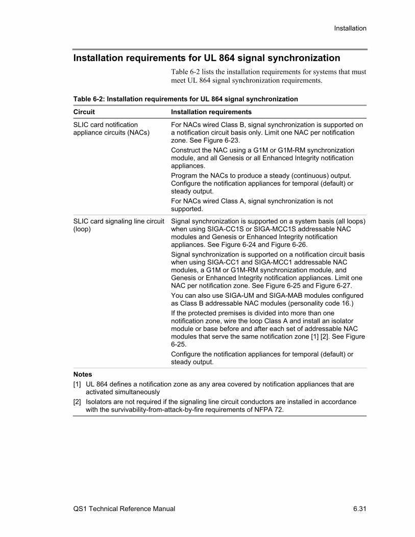
Installation
QS1 Technical Reference Manual 6.31
Installation requirements for UL 864 signal synchronization Table 6-2 lists the installation requirements for systems that must meet UL 864 signal synchronization requirements.
Table 6-2: Installation requirements for UL 864 signal synchronization
Circuit Installation requirements
SLIC card notification appliance circuits (NACs)
For NACs wired Class B, signal synchronization is supported on a notification circuit basis only. Limit one NAC per notification zone. See Figure 6-23.
Construct the NAC using a G1M or G1M-RM synchronization module, and all Genesis or all Enhanced Integrity notification appliances.
Program the NACs to produce a steady (continuous) output. Configure the notification appliances for temporal (default) or steady output.
For NACs wired Class A, signal synchronization is not supported.
SLIC card signaling line circuit (loop)
Signal synchronization is supported on a system basis (all loops) when using SIGA-CC1S or SIGA-MCC1S addressable NAC modules and Genesis or Enhanced Integrity notification appliances. See Figure 6-24 and Figure 6-26.
Signal synchronization is supported on a notification circuit basis when using SIGA-CC1 and SIGA-MCC1 addressable NAC modules, a G1M or G1M-RM synchronization module, and Genesis or Enhanced Integrity notification appliances. Limit one NAC per notification zone. See Figure 6-25 and Figure 6-27.
You can also use SIGA-UM and SIGA-MAB modules configured as Class B addressable NAC modules (personality code 16.)
If the protected premises is divided into more than one notification zone, wire the loop Class A and install an isolator module or base before and after each set of addressable NAC modules that serve the same notification zone [1] [2]. See Figure 6-25.
Configure the notification appliances for temporal (default) or steady output.
Notes
[1] UL 864 defines a notification zone as any area covered by notification appliances that are activated simultaneously
[2] Isolators are not required if the signaling line circuit conductors are installed in accordance with the survivability-from-attack-by-fire requirements of NFPA 72.
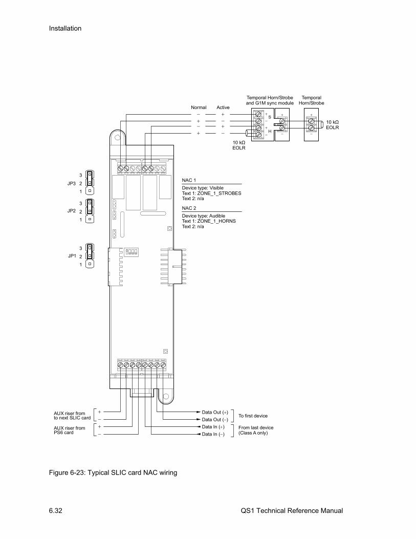
Installation
6.32 QS1 Technical Reference Manual
S
H
Temporal Horn/Strobeand G1M sync module
10 kEOLR
Ω
TemporalHorn/Strobe
3
2
1
3
2
1
3
2
1
JP1
JP2
JP3
Normal Active
NAC 2
Device type: AudibleText 1: ZONE_1_HORNSText 2: n/a
NAC 1
Device type: VisibleText 1: ZONE_1_STROBESText 2: n/a
Data Out ( )
Data Out ( )To first device
Data In ( )
Data In ( )From last device(Class A only)
AUX riser fromPS6 card
AUX riser fromto next SLIC card
10 kEOLR
Ω
Figure 6-23: Typical SLIC card NAC wiring
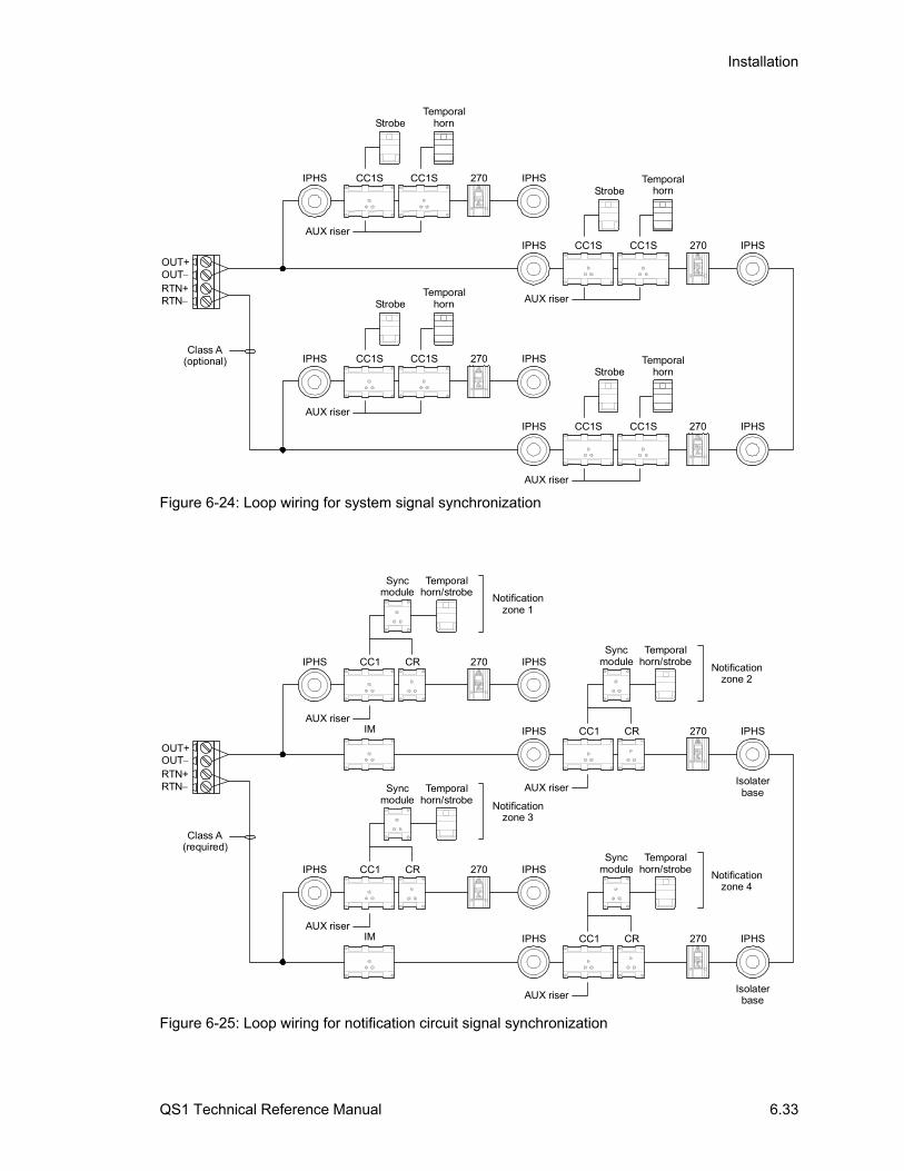
Installation
QS1 Technical Reference Manual 6.33
OUT+OUTRTN+RTN
Class A(optional)
IPHS 270CC1S CC1S
TemporalhornStrobe
IPHS
AUX riser
IPHS 270CC1S CC1S
TemporalhornStrobe
IPHS
AUX riser
IPHS 270CC1S CC1S
TemporalhornStrobe
IPHS
AUX riser
IPHS 270CC1S CC1S
TemporalhornStrobe
IPHS
AUX riser
Figure 6-24: Loop wiring for system signal synchronization
IM
IM
OUT+OUTRTN+RTN
Class A(required)
Isolaterbase
Isolaterbase
IPHS
IPHS
270
270
CC1
CC1
CR
CR
IPHS
IPHS
AUX riser
AUX riser
Notificationzone 1
Notificationzone 3
Temporalhorn/strobe
Temporalhorn/strobe
Syncmodule
Syncmodule
IPHS
IPHS
270
270
CC1
CC1
CR
CR
IPHS
IPHS
AUX riser
AUX riser
Notificationzone 2
Notificationzone 4
Temporalhorn/strobe
Temporalhorn/strobe
Syncmodule
Syncmodule
Figure 6-25: Loop wiring for notification circuit signal synchronization
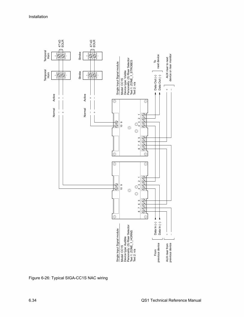
Installation
6.34 QS1 Technical Reference Manual
47 k
EO
LRΩ
Tem
pora
lH
orn
A
UX
ris
er fr
ompr
evio
us d
evic
e
12
34
56
78
91
0
12
34
56
78
91
0
Dat
a In
()
Dat
a In
()
Fro
mpr
evio
us d
evic
eD
ata
Out
()
Dat
a O
ut (
)
Ton
ext
devi
ce
A
UX
ris
er t
o ne
xtde
vice
or
riser
mon
itor
Sin
gle
Inpu
t Sig
nal m
odu
le
Mod
el:
CC
1S
Dev
ice
type
: Aud
ible
Per
sona
lity:
(5)
Ris
er S
ele
cto
rTe
xt 1
: Z
ON
E_1
_HO
RN
STe
xt 2
: n/
a
Sin
gle
Inpu
t Sig
nal m
odu
le
Mod
el:
CC
1SD
evic
e ty
pe: V
isib
leP
erso
nalit
y: (
5) R
iser
Sel
ect
or
Text
1: Z
ON
E_1
_S
TR
OB
ES
Text
2: n
/a
Tem
por
al
Hor
n
47 k
EO
LRΩ
Str
obe
Str
obe
Nor
ma
l
Act
ive
Nor
ma
lA
ctiv
e
Figure 6-26: Typical SIGA-CC1S NAC wiring
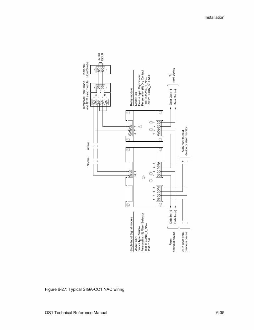
Installation
QS1 Technical Reference Manual 6.35
S H
Tem
pora
l Hor
n/S
trob
ean
d G
1M s
ync
mo
dule
47
kE
OLRΩ
Tem
por
al
Ho
rn/S
tro
be
A
UX
ris
er fr
omp
revi
ous
devi
ce
12
34
56
78
91
07
8
12
34
6
N
orm
al
Act
ive
Dat
a In
()
Dat
a In
()
Fro
mp
revi
ous
devi
ceD
ata
Out
()
Dat
a O
ut (
)
Tone
xt d
evi
ce
A
UX
ris
er to
ne
xtde
vice
or
riser
mo
nito
r
Rel
ay m
odu
le
Mod
el: C
RD
evic
e ty
pe: D
ry C
onta
ctP
erso
nalit
y: (
8) D
ry C
onta
ctTe
xt 1
: ZO
NE
_1_
NA
CTe
xt 2
: HO
RN
_SIL
EN
CE
Sin
gle
Inp
ut S
igna
l mod
ule
Mod
el: C
C1
Dev
ice
type
: Vis
ible
Per
sona
lity:
(5)
Ris
er
Sel
ecto
rTe
xt 1
: ZO
NE
_1_
NA
CTe
xt 2
: n/a
Figure 6-27: Typical SIGA-CC1 NAC wiring

Installation
6.36 QS1 Technical Reference Manual

QS1 Technical Reference Manual 7.1
Chapter 7 Front panel programming
Summary
This chapter provides instructions for programming the fire alarm system from the control panel CPU/Display Unit. It is intended for those trained and authorized to program the fire alarm system.
Content
UL 864 programming requirements • 7.2 Before you begin • 7.4
What is a zone? • 7.4 What is an output group? • 7.4 What is a service group? • 7.7 Using the AutoLearn command • 7.7 Using the Auto Loop command • 7.8
Device type descriptions • 7.9 Alarm device types • 7.9 Supervisory device types • 7.10 Trouble device types • 7.11 Monitor device types • 7.11 Output device types • 7.11
Programming limits • 7.13 Changing level 3 and level 4 passwords • 7.14 Configuring the system automatically • 7.15 Configuring the system • 7.16 Configuring SLIC cards • 7.21 Configuring addressable detectors • 7.25 Configuring addressable modules • 7.27 Configuring DLD cards • 7.37 Configuring receiver accounts • 7.40 Configuring output groups • 7.47 Configuring zones • 7.59 Clearing the history log • 7.65 Saving the project database • 7.66
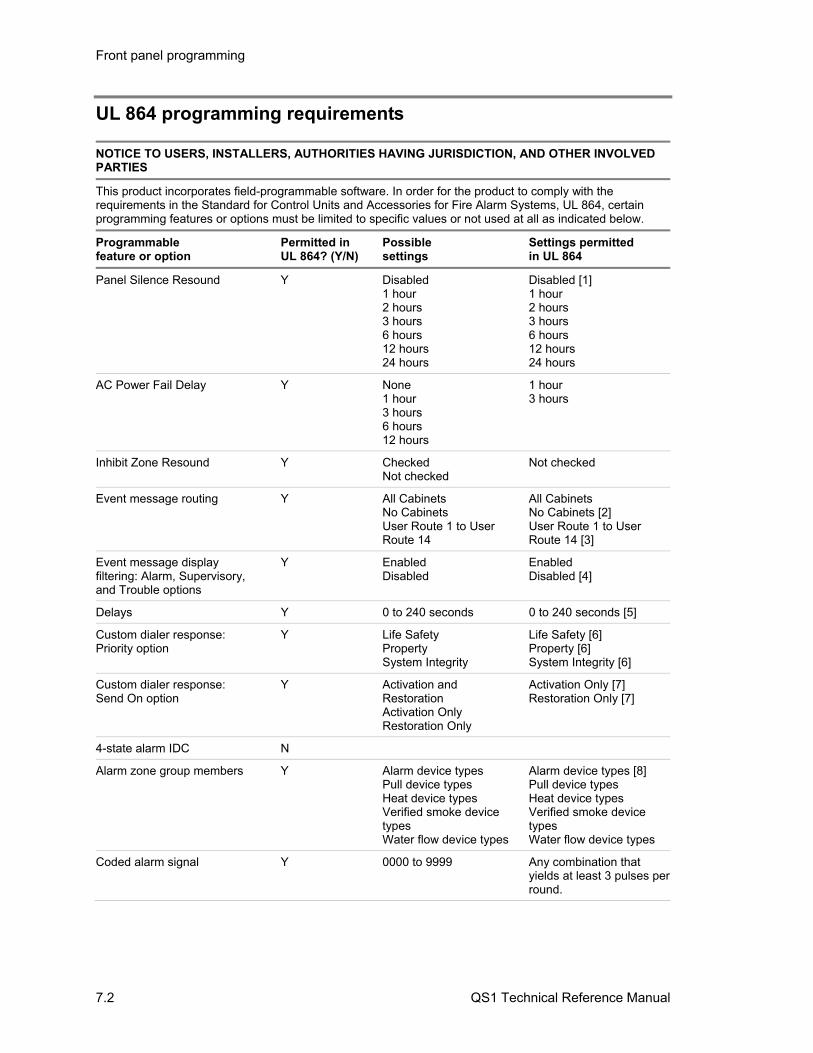
Front panel programming
7.2 QS1 Technical Reference Manual
UL 864 programming requirements
NOTICE TO USERS, INSTALLERS, AUTHORITIES HAVING JURISDICTION, AND OTHER INVOLVED PARTIES
This product incorporates field-programmable software. In order for the product to comply with the requirements in the Standard for Control Units and Accessories for Fire Alarm Systems, UL 864, certain programming features or options must be limited to specific values or not used at all as indicated below.
Programmable feature or option
Permitted in UL 864? (Y/N)
Possible settings
Settings permitted in UL 864
Panel Silence Resound Y Disabled 1 hour 2 hours 3 hours 6 hours 12 hours 24 hours
Disabled [1] 1 hour 2 hours 3 hours 6 hours 12 hours 24 hours
AC Power Fail Delay Y None 1 hour 3 hours 6 hours 12 hours
1 hour 3 hours
Inhibit Zone Resound Y Checked Not checked
Not checked
Event message routing Y All Cabinets No Cabinets User Route 1 to User Route 14
All Cabinets No Cabinets [2] User Route 1 to User Route 14 [3]
Event message display filtering: Alarm, Supervisory, and Trouble options
Y Enabled Disabled
Enabled Disabled [4]
Delays Y 0 to 240 seconds 0 to 240 seconds [5]
Custom dialer response: Priority option
Y Life Safety Property System Integrity
Life Safety [6] Property [6] System Integrity [6]
Custom dialer response: Send On option
Y Activation and Restoration Activation Only Restoration Only
Activation Only [7] Restoration Only [7]
4-state alarm IDC N
Alarm zone group members Y Alarm device types Pull device types Heat device types Verified smoke device types Water flow device types
Alarm device types [8] Pull device types Heat device types Verified smoke device types Water flow device types
Coded alarm signal Y 0000 to 9999 Any combination that yields at least 3 pulses per round.
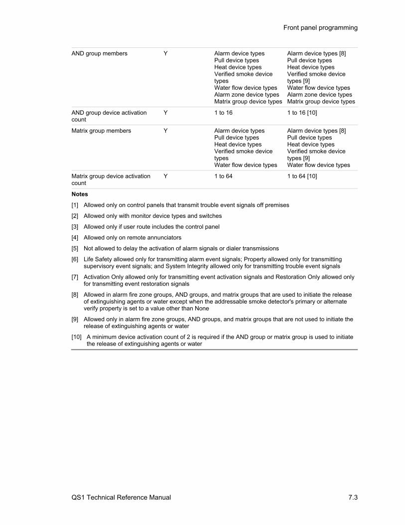
Front panel programming
QS1 Technical Reference Manual 7.3
AND group members Y Alarm device types Pull device types Heat device types Verified smoke device types Water flow device types Alarm zone device typesMatrix group device types
Alarm device types [8] Pull device types Heat device types Verified smoke device types [9] Water flow device types Alarm zone device typesMatrix group device types
AND group device activation count
Y 1 to 16 1 to 16 [10]
Matrix group members Y Alarm device types Pull device types Heat device types Verified smoke device types Water flow device types
Alarm device types [8] Pull device types Heat device types Verified smoke device types [9] Water flow device types
Matrix group device activation count
Y 1 to 64 1 to 64 [10]
Notes
[1] Allowed only on control panels that transmit trouble event signals off premises
[2] Allowed only with monitor device types and switches
[3] Allowed only if user route includes the control panel
[4] Allowed only on remote annunciators
[5] Not allowed to delay the activation of alarm signals or dialer transmissions
[6] Life Safety allowed only for transmitting alarm event signals; Property allowed only for transmitting supervisory event signals; and System Integrity allowed only for transmitting trouble event signals
[7] Activation Only allowed only for transmitting event activation signals and Restoration Only allowed only for transmitting event restoration signals
[8] Allowed in alarm fire zone groups, AND groups, and matrix groups that are used to initiate the release of extinguishing agents or water except when the addressable smoke detector's primary or alternate verify property is set to a value other than None
[9] Allowed only in alarm fire zone groups, AND groups, and matrix groups that are not used to initiate the release of extinguishing agents or water
[10] A minimum device activation count of 2 is required if the AND group or matrix group is used to initiate the release of extinguishing agents or water

Front panel programming
7.4 QS1 Technical Reference Manual
Before you begin This topic describes several programming features that you should understand before you begin programming the fire alarm system.
What is a zone?
A zone is a collection of points that are grouped together in the project database in the same manner that the system designer divided the protected premises. Zones provide a single zonal response and are used to limit the number of event messages processed by the system. Firewall designations, planned evacuation criteria, architectural design, and other factors determine how points are grouped into zones.
What is an output group?
An output group is a collection of responses organized into sets according to specific response types. The response types for which you can create and edit responses from the control panel CPU/Display Unit are described below.
Active: The set of responses executed when a point assigned to the output group changes to the active state.
Trouble: The set of responses executed when a point assigned to the output group signals a trouble condition.
In addition to active and trouble responses, there are a number of response types for which you can create and edit responses using the software configuration utility. These response types are described below.
Active Test: The set of responses executed when a point in a service group assigned to the output group changes to the active state and the service group is active.
Disablement: The set of responses executed when a point assigned to the output group changes to the disabled state.
Trouble Test: The set of responses executed when a point in a service group assigned to the output group signals a trouble condition and the service group is active.
Pre Alarm: The set of responses executed when a fire alarm detector assigned to the output group signals that its prealarm threshold has been crossed.
Running: The set of responses executed when a service group assigned to the output group is activated.
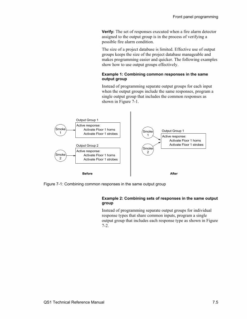
Front panel programming
QS1 Technical Reference Manual 7.5
Verify: The set of responses executed when a fire alarm detector assigned to the output group is in the process of verifying a possible fire alarm condition.
The size of a project database is limited. Effective use of output groups keeps the size of the project database manageable and makes programming easier and quicker. The following examples show how to use output groups effectively.
Example 1: Combining common responses in the same output group
Instead of programming separate output groups for each input when the output groups include the same responses, program a single output group that includes the common responses as shown in Figure 7-1.
Before
Output Group 1
Smoke1
Active response:Activate Floor 1 hornsActivate Floor 1 strobes
Output Group 2
Smoke2
Active response:Activate Floor 1 hornsActivate Floor 1 strobes
After
Output Group 1
Active response:Activate Floor 1 hornsActivate Floor 1 strobes
Smoke2
Smoke1
Figure 7-1: Combining common responses in the same output group
Example 2: Combining sets of responses in the same output group
Instead of programming separate output groups for individual response types that share common inputs, program a single output group that includes each response type as shown in Figure 7-2.
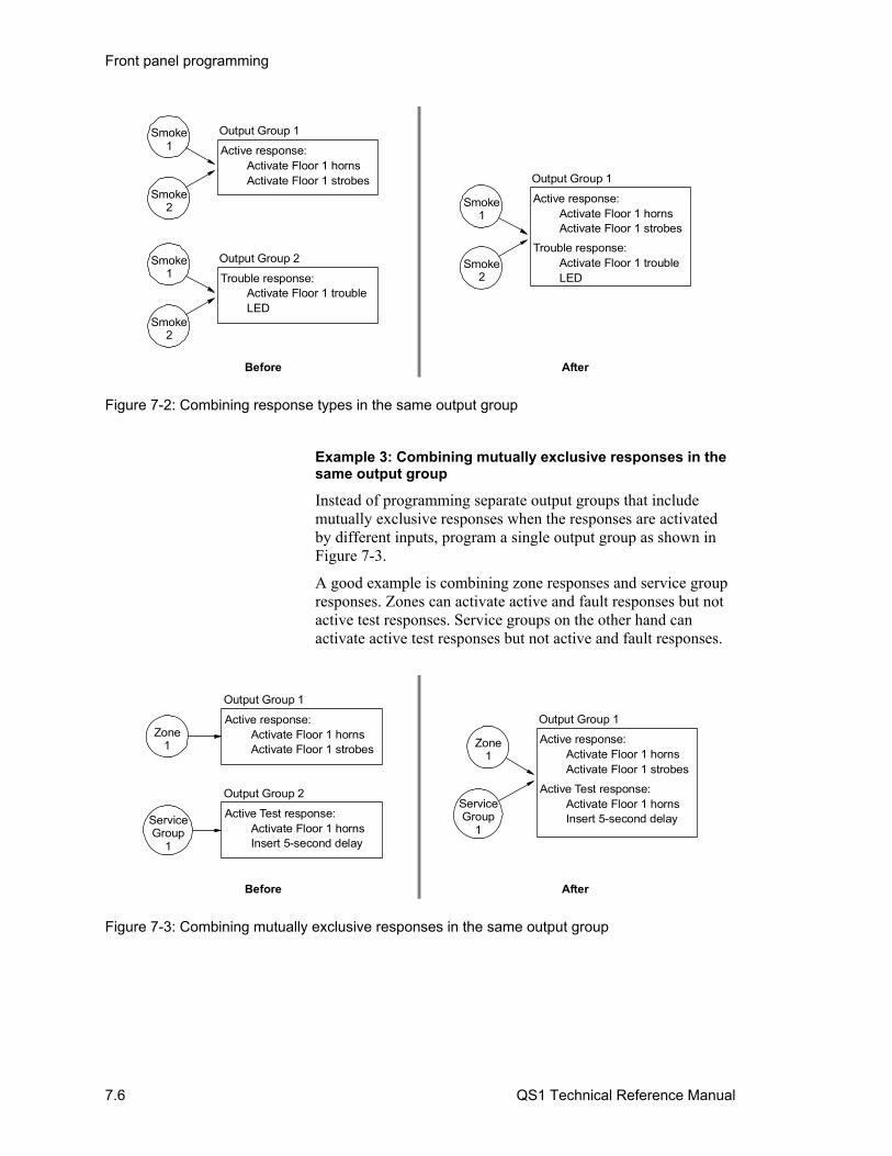
Front panel programming
7.6 QS1 Technical Reference Manual
Before After
Output Group 1
Active response:Activate Floor 1 hornsActivate Floor 1 strobes
Smoke2
Smoke1
Output Group 2
Trouble response:Activate Floor 1 trouble LED
Smoke2
Smoke1
Output Group 1
Active response:Activate Floor 1 hornsActivate Floor 1 strobes
Trouble response:Activate Floor 1 trouble LED
Smoke2
Smoke1
Figure 7-2: Combining response types in the same output group
Example 3: Combining mutually exclusive responses in the same output group
Instead of programming separate output groups that include mutually exclusive responses when the responses are activated by different inputs, program a single output group as shown in Figure 7-3.
A good example is combining zone responses and service group responses. Zones can activate active and fault responses but not active test responses. Service groups on the other hand can activate active test responses but not active and fault responses.
Before After
Output Group 1
Zone1
Active response:Activate Floor 1 hornsActivate Floor 1 strobes
Output Group 2
ServiceGroup
1
Active Test response:Activate Floor 1 hornsInsert 5-second delay
Output Group 1
Active response:Activate Floor 1 hornsActivate Floor 1 strobes
Active Test response:Activate Floor 1 hornsInsert 5-second delay
Zone1
ServiceGroup
1
Figure 7-3: Combining mutually exclusive responses in the same output group
Front panel programming
QS1 Technical Reference Manual 7.7
What is a service group?
A service group is a collection of points in the project database that are grouped together to facilitate periodic system testing. Service groups can comprise all of the devices in the protected premises or you can divide the protected premises into multiple service groups to lessen the impact periodic testing has on the building occupants.
By default, the system provides one service group (service group129) that allows a service technician to perform an active test and a fault test on every device in the system. To program multiple service groups you must use the software configuration utility.
Using the AutoLearn command
Use the AutoLearn command to automatically configure the control panel and remote annunciators from their respective CPU/Display Units. The AutoLearn command lets you:
• Assign panel numbers • Designate how the control panel and remote annunciators are
wired together • Detect which option cards are installed in the control panel
The AutoLearn command replaces the existing project database with a default project database based on the hardware configuration it detects. The default project database configures the system as a general fire alarm system that activates all notification appliance circuits when any fire alarm input is activated. The default project database also includes one service group (129) and two output groups (31 and 32).
Service Group 129 consists of all fire alarm, supervisory, and monitor device types that are not members of another service group.
Output Group 31 provides an active test response that briefly turns on all Alarm Output device types and the Visible device types detected when the default project database was created. The active test response does not turn on any Audible, Visible, or Output device types added after the default database was created. The active test response is activated when a member of Service Group 129 changes to the active or trouble state and Service Group 129 is active.
Output Group 32 provides an active response that turns on the Visible device types detected when the default project database was created. The active response does not turn on any Audible, Visible, or Output device types added after the default project database was created. The active response is activated when the control panel enters the alarm state.

Front panel programming
7.8 QS1 Technical Reference Manual
Using the Auto Loop command
Use Auto Loop command to automatically add the intelligent addressable devices to the SLIC card. The Auto Loop command replaces the data in the SLIC card’s actual data table with the devices it finds installed on the loop. For more information, see “Adding intelligent addressable devices automatically” later in this chapter.

Front panel programming
QS1 Technical Reference Manual 7.9
Device type descriptions Device types determine the operation of the points to which they are assigned. The device types that can be used to program the system are described below.
Alarm device types
Alarm device types are assigned to addressable devices and initiating device circuits (IDCs) used to activate alarm signals. The alarm device types that you can assign are described below.
Alarm Active: Device type typically assigned to addressable IDCs connected to two-wire smoke detectors or dry contact devices. You can also assign this device type to addressable pull stations. Alarm active device types initiate alarm events and this event message: ALARM ACTIVE
Alarm Verify: Device type assigned to addressable IDCs connected to two-wire smoke detectors that you want verified before initiating an alarm event.
When smoke is first detected, alarm verify device types initiate a monitor event and this event message: ALARM VERIFY. If smoke is still present at the end of the alarm verification period, alarm verify device types initiate an alarm event and this event message: ALARM ACTIVE.
Alarm verification helps prevent false alarms in areas where transient smoke is anticipated by resetting the smoke detector after it first latches then waiting to see if it latches again within the designated confirmation period. The figure below shows the alarm verification timing.
8 s 16 s 60 s
Control unit
Retard-resetperiod
Detectorrestart
Power-upperiod
Retard-reset-restart period
No alarm at control unit
Confirmation period
Alarm required at control unit
Alarm verification period
Heat Alarm: Device type typically assigned to addressable heat detectors and to addressable IDCs connected only to heat detectors. Heat device types initiate alarm events and this event message: HEAT ALARM.
Front panel programming
7.10 QS1 Technical Reference Manual
Note: The personality code of addressable IDCs connected to duct smoke detectors must be set to active latching.
Pull Station: Device type typically assigned to addressable pull stations and to addressable IDCs connected only to pull stations. Pull station device types initiate alarm events and this event message: PULL STATION.
Waterflow: Device type typically assigned to addressable IDCs connected only to waterflow switches. Waterflow device types initiate alarm events and this event message: WATERFLOW.
Supervisory device types
Supervisory device types are assigned to addressable initiating device circuits (IDCs) used to activate supervisory signals. The supervisory device types that you can assign are described below.
Latch Supv: Device type typically assigned to addressable IDCs connected to supervisory switches other than control valve supervisory switches. You can also assign this device type to addressable IDCs connected to conventional duct smoke detectors.
Latching supervisory device types initiate supervisory events with this event message: LATCH SUPV. Latching supervisory device types restore only after the condition that initiated them is restored and the panel is reset.
Latch Tamper: Device type typically assigned to addressable IDCs connected to control valve supervisory switches, such as an OS&Y valve supervisory switch.
Latching tamper device types initiate supervisory events with this event message: LATCH TAMPER. Latching tamper device types restore only after the condition that initiated them is restored and the panel is reset.
Supervisory: Device type typically assigned to addressable IDCs connected to supervisory switches other than control valve supervisory switches. You can also assign this device type to addressable IDCs connected to conventional duct smoke detectors.
Supervisory device types initiate supervisory events with this event message: SUPERVISORY. Supervisory device types automatically restore after the condition that initiated them is restored.
Tamper: Device type typically assigned to addressable IDCs connected to control valve supervisory switches, such as an OS&Y valve supervisory switch.
Tamper device types initiate supervisory events with this event message: TAMPER. Tamper device types automatically restore after the condition that activated them is restored.
Front panel programming
QS1 Technical Reference Manual 7.11
Trouble device types
Trouble device types are assigned to addressable initiating device circuits (IDCs) used to activate trouble signals. The trouble device types that you can assign are described below.
AC Pwr Fail: Device type assigned to addressable IDCs connected to the trouble relay on an auxiliary/booster power supply. AC power fail device types initiate trouble events with this event message: AC POWER FAIL.
Monitor device types
Monitor device types are assigned to addressable initiating device circuits (IDCs) used to activate monitor signals. The monitor device types that you can assign are described below.
Monitor: Device type assigned to addressable IDCs connected to switches that monitor the operation of ancillary system functions. For example, fan feedback switches.
Monitor device types initiate monitor events with this event message: MONITOR. Monitor device types are nonlatching. They automatically restore after the condition that activated them is restored.
Output device types
Output device types are assigned to notification appliance circuits (NACs) and relays. The output device types that you can assign are described below.
Common alarm output: Device type assigned to NACs connected to horns, strobes, or both. You can also assign this device type to controls for ancillary equipment in applications that require circuit supervision. Common alarm output device types:
• Turn on automatically with any alarm event. Programming is not required.
• Turn off automatically when Alarm Silence is pressed
• Turn on automatically when Drill is pressed
• Can’t be disabled
Abbreviated: COM ALARM OUT
Audible: Device type typically assigned to NACs connected only to horns. Audible device types:
• Must be programmed to turn on
• Turn off automatically when Alarm Silence is pressed
• Turn on automatically when Drill is pressed

Front panel programming
7.12 QS1 Technical Reference Manual
• Can be disabled
Dry contact: Device type assigned to addressable relays and to ZR8 card relays connected to controls for ancillary equipment in applications that don't require circuit supervision. Dry contact device types:
• Must be programmed to turn on or off
• Do not turn off when Alarm Silence is pressed, unless programmed to do so
• Do not turn on when Drill is pressed, unless programmed to do so
• Can be disabled
Supervised output: Device type typically assigned to NACs connected to controls for ancillary equipment in applications that require circuit supervision. Supervised output device types:
• Must be programmed to turn on
• Do not turn off when Alarm Silence is pressed, unless programmed to do so
• Do not turn on when Drill is pressed, unless programmed to do so
• Can be disabled
Abbreviated: OUTPUT
Visual: Device type typically assigned to NACs connected to strobes. Visible device types:
• Must be programmed to turn on or off
• Do not turn off automatically when Alarm Silence is pressed, unless configured to do so
• Do not turn on automatically when Drill is pressed, unless configured to do so
• Can be disabled
Also called Visible device type.

Front panel programming
QS1 Technical Reference Manual 7.13
Programming limits Table 7-1 lists the maximum limits for front panel programming and the software configuration utility.
Table 7-1: Front panel and software configuration utility programming limits
Feature Front panel Software configuration utility
Zones Quantity: 480 Members: 32 Output groups per zone: 6
Quantity: 480 Members: 32 Output groups per zone: 16
Output groups Quantity: 250 Devices activating an output group: limited to zones
Quantity: 250 Devices activating an output group: unlimited
Service groups None [1] Quantity: 128 Members: unlimited Output groups per service group: 16
AND groups None Quantity: 64 Members: 16 Output groups per AND group: 16
Matrix groups None Quantity: 64 Members: 64 Output groups per matrix group: 16
Time controls None Quantity: 32 Output groups per time control: 16
Switch groups None [2] 16
Notes
[1] A single service group (service group 129) is automatically created that allows the periodic testing of the entire system and cannot be changed through front panel programming
[2] Switch groups 1 and 2 are automatically assigned and cannot be changed through front panel programming
3. A device can’t be a member of more than one zone, one service group, five AND groups, and five matrix groups at the same time
4. The project database can’t have more than 1,356 objects
Front panel programming
7.14 QS1 Technical Reference Manual
Changing level 3 and level 4 passwords Use the Edit Password command on the Program menu to change the password setting for using level 3 and level 4 command menus.
To change the level 3 and level 4 passwords you must log on using the level 4 password.
The default level 3 password is 3333.
The default level 4 password is 4444.
To change the level 3 or level 4 password:
1. On the Main menu, choose Program.
2. On the Program menu, choose Edit Password.
3. On the Password menu, choose Level 3 or Level 4.
4. Enter the new password then wait while the database is updated.

Front panel programming
QS1 Technical Reference Manual 7.15
Configuring the system automatically Use the AutoLearn command on the Configure menu to configure the control panel and remote annunciators from their respective CPU/Display Units. For more information about the AutoLearn command, see “Automatically configuring the system” earlier in this chapter.
Caution: Do not use the AutoLearn command if you have made any changes to the project database from the front panel or have downloaded a project database from the software configuration utility. The AutoLearn command replaces the existing project configuration settings with default values that may be contrary to those you have programmed.
Note: Before proceeding, if configuring a control panel, view a revision report to make sure that all optional panel components are accounted for and are addressed correctly. For more information, see “Display or print a revision report” in Chapter 8.
To configure the system automatically:
1. Log on to the panel using the level 4 password.
2. From the Main menu, choose Program, then Configure, and then AutoLearn.
3. If configuring a control panel, enter a panel ID number of 01.
If configuring a remote annunciator, enter a panel ID from 02 to 09.
4. Enter the total number of panels in the system (the control panel plus all remote annunciators).
5. On the Network Class menu, select the wiring configuration (Class A or Class B) of the RS-485 transmission path, and then press Enter.

Front panel programming
7.16 QS1 Technical Reference Manual
Configuring the system To configure the system, follow the procedure below. In addition, refer to Figure 7-4. System options are described in Table 7-2. A complete list is provided in Table 7-3.
Table 7-2: System options
Option Description
Facility Name Text displayed on the LCD when the control panel is normal. Typically, the name of the protected premises.
Inst Company The name of the company that installed the fire alarm system (i.e., your company’s name.) Used for record-keeping purposes only.
Phone Number The installing company’s phone number. Used for record-keeping purposes only.
Programmer The name of the person who programmed the fire alarm system. Used for record-keeping purposes only.
ALM/RST Inhib The amount of time you must wait after an alarm event before you can silence alarm signals or reset the control panel.
Possible values: None, 1, 3, or 5 minutes
Default: None
AC Power Dly The amount of time the control panel waits before transmitting AC power fail events off premises.
Possible values: None, 1, 3, 6, or 12 hours
Default: 3 hours.
To configure the system:
1. On the Configure menu, choose System then on the Config System menu:
• To enter text for the banner and other labels, choose User labels
• To change the value of alarm signal/reset inhibit, choose ALM/RST Inhib on the ALARM/RESET Inhib menu:
Choose 1, 3, or 5 minutes.
— or —
Choose None to disable the alarm signal/reset inhibit feature.
• To change the value of AC power delay, choose AC Power DLY then on the AC Power Delay menu:
Choose 1, 3, 6, or 12 hours.
— or —
Note: To meet UL 864 requirements, set the AC Power Dly option for either 1 or 3 hours.

Front panel programming
QS1 Technical Reference Manual 7.17
Choose None to disable the AC power delay feature.
• To quit and return to the Configure menu, choose Exit then on the Exit menu:
Choose Save Edits to save your changes.
— or —
Choose NO Save to quit without saving your changes.
2. On the User Labels menu:
• To enter the text you want displayed when the panel is normal, choose Facility Name then enter the text. To enter text you must use a compatible bar code scanner.
• To enter your company’s name, choose Inst Company
• To enter the phone number of the person to contact about the control panel, choose Phone Number
• To enter the name of the person to contact about the system’s programming, choose Programmer
• To quit and return to the Configure menu, choose Exit then on the Exit menu:
Choose Save Edits to save your changes.
— or —
Choose NO Save to quit without saving your changes.
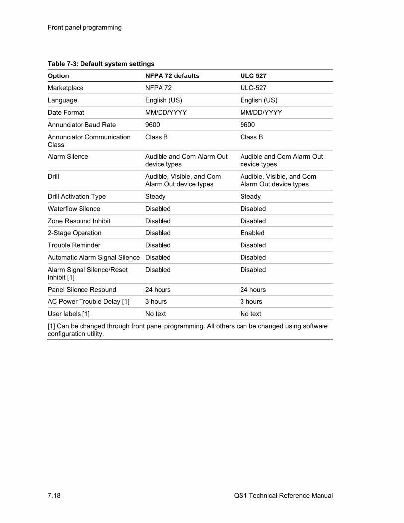
Front panel programming
7.18 QS1 Technical Reference Manual
Table 7-3: Default system settings
Option NFPA 72 defaults ULC 527
Marketplace NFPA 72 ULC-527
Language English (US) English (US)
Date Format MM/DD/YYYY MM/DD/YYYY
Annunciator Baud Rate 9600 9600
Annunciator Communication Class
Class B Class B
Alarm Silence Audible and Com Alarm Out device types
Audible and Com Alarm Out device types
Drill Audible, Visible, and Com Alarm Out device types
Audible, Visible, and Com Alarm Out device types
Drill Activation Type Steady Steady
Waterflow Silence Disabled Disabled
Zone Resound Inhibit Disabled Disabled
2-Stage Operation Disabled Enabled
Trouble Reminder Disabled Disabled
Automatic Alarm Signal Silence Disabled Disabled
Alarm Signal Silence/Reset Inhibit [1]
Disabled Disabled
Panel Silence Resound 24 hours 24 hours
AC Power Trouble Delay [1] 3 hours 3 hours
User labels [1] No text No text
[1] Can be changed through front panel programming. All others can be changed using software configuration utility.

Front panel programming
QS1 Technical Reference Manual 7.19
CONFIGURE 1)AutoLearn2)System 3)Cards 4)Zones 5)Output 6)Exit
CONFIG SYSTEM1)User Labels 2)ALM/RST Inhib 3)AC Power Dly 4)Exit
B
ALARM/RESET INHI1)None 2)1 min 3)3 min 4)5 min
AC POWER DELAY 1)None 2)1 Hour3)3 Hours 4)6 Hours 5)12 Hours
EXIT1)Save Edits 2)NO Save
A
2
3
4
1 Sheet 2
Sheet 2
Figure 7-4: System configuration diagram (sheet 1 of 2)
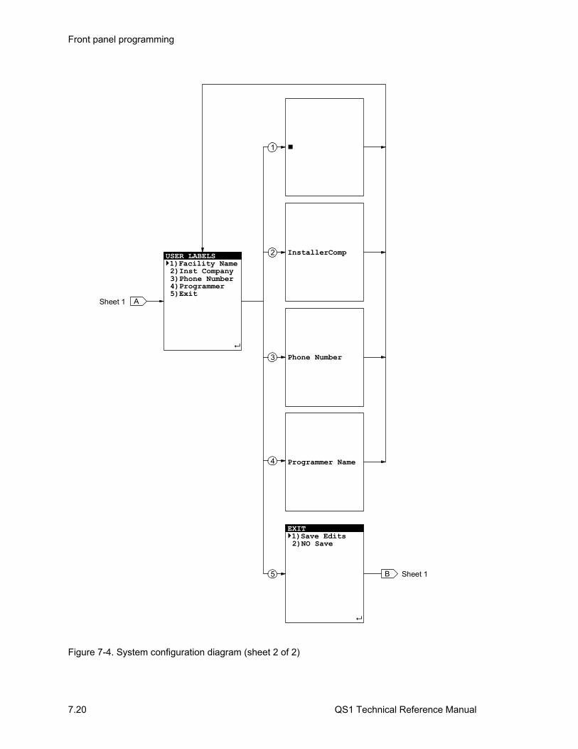
Front panel programming
7.20 QS1 Technical Reference Manual
USER LABELS1)Facility Name 2)Inst Company 3)Phone Number 4)Programmer 5)Exit
Sheet 1
A
InstallerComp
Phone Number
Programmer Name
EXIT1)Save Edits 2)NO Save
1
2
3
4
5 B
Sheet 1
Figure 7-4. System configuration diagram (sheet 2 of 2)
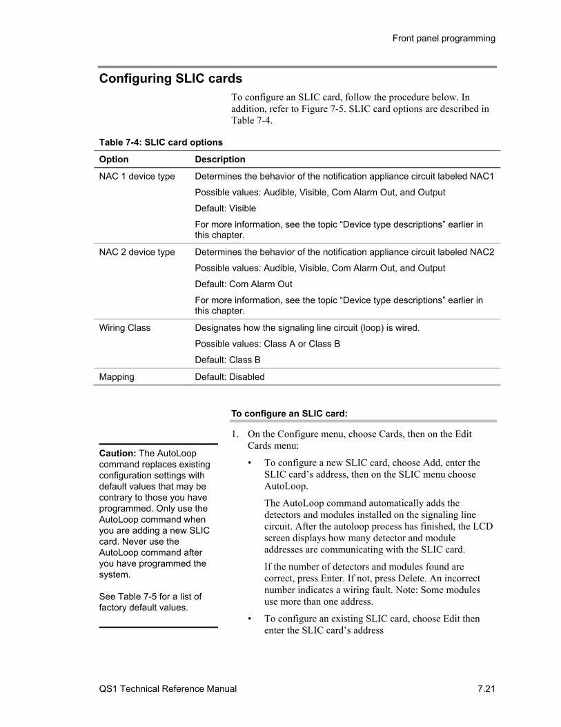
Front panel programming
QS1 Technical Reference Manual 7.21
Configuring SLIC cards To configure an SLIC card, follow the procedure below. In addition, refer to Figure 7-5. SLIC card options are described in Table 7-4.
Table 7-4: SLIC card options
Option Description
NAC 1 device type Determines the behavior of the notification appliance circuit labeled NAC1
Possible values: Audible, Visible, Com Alarm Out, and Output
Default: Visible
For more information, see the topic “Device type descriptions” earlier in this chapter.
NAC 2 device type Determines the behavior of the notification appliance circuit labeled NAC2
Possible values: Audible, Visible, Com Alarm Out, and Output
Default: Com Alarm Out
For more information, see the topic “Device type descriptions” earlier in this chapter.
Wiring Class Designates how the signaling line circuit (loop) is wired.
Possible values: Class A or Class B
Default: Class B
Mapping Default: Disabled
To configure an SLIC card:
1. On the Configure menu, choose Cards, then on the Edit Cards menu:
• To configure a new SLIC card, choose Add, enter the SLIC card’s address, then on the SLIC menu choose AutoLoop.
The AutoLoop command automatically adds the detectors and modules installed on the signaling line circuit. After the autoloop process has finished, the LCD screen displays how many detector and module addresses are communicating with the SLIC card.
If the number of detectors and modules found are correct, press Enter. If not, press Delete. An incorrect number indicates a wiring fault. Note: Some modules use more than one address.
• To configure an existing SLIC card, choose Edit then enter the SLIC card’s address
Caution: The AutoLoop command replaces existing configuration settings with default values that may be contrary to those you have programmed. Only use the AutoLoop command when you are adding a new SLIC card. Never use the AutoLoop command after you have programmed the system.
See Table 7-5 for a list of factory default values.

Front panel programming
7.22 QS1 Technical Reference Manual
• To delete a SLIC card and return to the Configure menu, choose Delete then enter the SLIC card’s address
2. On the SLIC menu:
• To configure card options, choose Config Card
• To configure addressable detectors, choose Config Detect. For a detailed procedure, see “Configuring addressable detectors” later in this chapter
• To configure addressable modules, choose Config Module. For a detailed procedure, see “Configuring addressable modules” later in this chapter
• To quit and return to the Configure menu, choose Exit then on the Exit
Choose Save Edits to save your changes.
— or —
Choose NO Save to quit without saving your changes.
3. On the Configure Card menu:
• To change the device type for NAC 1, choose NAC 1 then on the NAC 1 menu choose the device type
• To change the device type for NAC 2, choose NAC 2 then on the NAC 2 menu choose the device type
• To change the performance class type of the signaling line circuit, choose Wiring Class then on the Wiring Class menu choose the class type
• To quit and return to the SLIC menu, choose Exit then on the Exit menu:
Choose Save Edits to save your changes.
— or —
Choose NO Save to quit without saving your changes.
SLIC card, detector, and module changes are not implemented immediately after you save them. The project database must be updated, the control panel must reboot, and the SLIC card must re-acquire the actual loop data before programming your changes. This process takes time. The time varies with the number of changes you make and the number of devices on the loop.

Front panel programming
QS1 Technical Reference Manual 7.23
If you need to test your changes, you must wait until after the devices have been reprogrammed. Before testing your changes, do one of the following:
• Use the front panel display to verify that a trouble event message is posted and then restored for each device that you changed
• Use the configuration utility to monitor the loop's status and verify that Device Supervision has ended

Front panel programming
7.24 QS1 Technical Reference Manual
Table 7-5: Factory default settings for addressable devices
Model Personality Device Type Description
IPHS, PHS, PS, IS none Alarm Smoke detector settings as follows: Sensitivity: Least Verification: None Prealarm: None
HFS, HRS, IM none Heat Heat detector settings not programmable
Single-stage pull stations
01 Pull Class B Alarm Latching
Dual-stage pull stations 01 Monitor Class B Alarm Latching
01 Pull Class B Alarm Latching
APS 03 Monitor Class B Active Nonlatching
03 Monitor Class B Active Nonlatching
CC1(S), MCC1(S) 05 Common Alarm Output
Riser selector
CC2, MCC2 07 Common Alarm Output
Dual riser selector
CR(R), MCR(R) 08 Nonsupervised Output
Dry contact
CT1, MCT1 01 Alarm Class B Alarm Latching
CT2, MCT2 01 Alarm Class B Alarm Latching
01 Alarm Class B Alarm Latching
DTS 01 Alarm Class B Alarm Latching
IO 31 Monitor Monitor Input/Output N.O.
MAB 04 Monitor Class A Signal Output
04 not used
UM 04 Monitor Class A Signal Output
04 not used
MM1 03 Monitor Class B Active Nonlatching
WTM 02 Alarm Class B Active Latching - Delayed
04 Supervisory Class B Active Latching
RM1, MRM1 23 Monitor Riser monitor - 24 Vdc

Front panel programming
QS1 Technical Reference Manual 7.25
Configuring addressable detectors To configure an addressable detector, follow the procedure below. In addition, refer to Figure 7-5. Detector options are described in Table 7-6.
Table 7-6: Detector options
Option Description
Message Text displayed as part of a detector’s event message. Typically, the text provides a location description.
Default: No message
Sensitivity Determines a smoke detector’s primary and alternate alarm threshold. The alarm threshold is the point at which the detector initiates an alarm event. This option is not available for heat detectors.
Possible values: Most, More, Normal, Less, and Least. These values represent %obscuration levels.
Default: Least
Verification Determines the duration of a smoke detector’s primary and alternate alarm verification cycle. This option is not available for heat detectors.
Possible values: None, 12, 24, 36, or 48 seconds. Other values are available using the configuration utility.
Default: None
Pre-alarm Determines a smoke detector’s primary and alternate pre-alarm threshold. The pre-alarm threshold is the point at which the detector initiates a monitor event to signal the possibility of a fire and is expressed as a percentage of the detector’s alarm threshold. This option not available for heat detectors.
Possible values: None, 20%, 40%, 60% or 80%. Other values are available using the configuration utility.
Default: None
Base type Designates the base onto which the detector is mounted.
Possible values: Standard, Relay, or Isolator
Default: Standard
Device type Determines the type of event the detector initiates. This option is not configurable from the control panel.
Defaults: Alarm (smoke detectors) or Heat (heat detectors)
To configure an addressable detector:
1. On the SLIC menu, choose Config Detect then on the Config Detector menu:
• To configure a new detector, choose Add then:

Front panel programming
7.26 QS1 Technical Reference Manual
Choose Device Addres then enter a device address for the detector
— or —
Choose Enter Serial# then enter the detector’s serial number
• To configure an existing detector, choose Edit then enter the detector’s device address or serial number
• To delete a detector, choose Delete then enter the detector’s device address or serial number
2. On the Config Detector menu:
• To enter the text for the detector’s event message, choose Message. To enter text you must use a compatible bar code scanner.
• To view the model number of the selected module, choose Model
• To change the detector’s primary and alternate alarm sensitivity, choose Sensitivity then on the Sensitivity menu choose Most, More, Normal, Less, or Least
• To change the detector’s alarm verification value, choose Verification then on the Verification menu:
Choose 12, 24, 36, or 48 seconds.
— or —
Choose None if you do not want to use the detector’s alarm verification feature.
• To change the detector’s primary and alternat pre-alarm value, choose Pre-Alarm then on the Pre-Alarm menu:
Choose 20%, 40%, 60% or 80%.
— or —
Choose None if you do not want to use the detector’s pre-alarm feature.
• To change the detector’s base, choose Base Type then on the Base Type menu choose Standard, Relay, or Isolator
• If you are deleting a detector or to quit and return to the Config Detector menu, choose Exit then on the Exit menu:
Choose Save Edits to save your changes.
— or —
Choose NO Save to quit without saving your changes.
Note: Changing the detector’s model type resets the current default option values to those of the new model type.
Alarm %obscuration levels for IPHS, PHS, and PS detectors
Most 1.0
More 2.0
Normal 2.5
Less 3.0
Least 3.5
Alarm %obscuration levels for IS detectors
Most 0.7
More 1.0
Normal 1.2
Less 1.4
Least 1.6
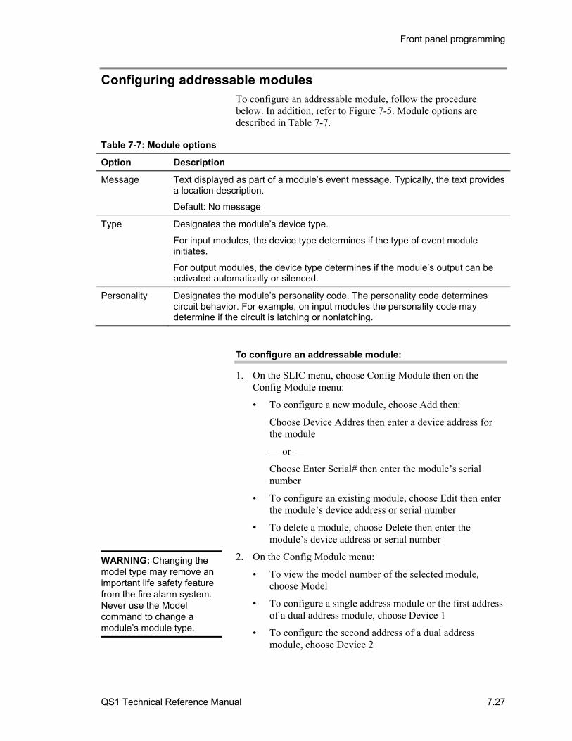
Front panel programming
QS1 Technical Reference Manual 7.27
Configuring addressable modules To configure an addressable module, follow the procedure below. In addition, refer to Figure 7-5. Module options are described in Table 7-7.
Table 7-7: Module options
Option Description
Message Text displayed as part of a module’s event message. Typically, the text provides a location description.
Default: No message
Type Designates the module’s device type.
For input modules, the device type determines if the type of event module initiates.
For output modules, the device type determines if the module’s output can be activated automatically or silenced.
Personality Designates the module’s personality code. The personality code determines circuit behavior. For example, on input modules the personality code may determine if the circuit is latching or nonlatching.
To configure an addressable module:
1. On the SLIC menu, choose Config Module then on the Config Module menu:
• To configure a new module, choose Add then:
Choose Device Addres then enter a device address for the module
— or —
Choose Enter Serial# then enter the module’s serial number
• To configure an existing module, choose Edit then enter the module’s device address or serial number
• To delete a module, choose Delete then enter the module’s device address or serial number
2. On the Config Module menu:
• To view the model number of the selected module, choose Model
• To configure a single address module or the first address of a dual address module, choose Device 1
• To configure the second address of a dual address module, choose Device 2
WARNING: Changing the model type may remove an important life safety feature from the fire alarm system. Never use the Model command to change a module’s module type.

Front panel programming
7.28 QS1 Technical Reference Manual
• If you are deleting a module or to quit configuring a module and return to the Config Module menu, choose Exit then on the Exit menu:
Choose Save Edits to save your changes
— or —
Choose NO Save to quit without saving your changes
3. For a single address module or the first address of a dual address module, on the Configure Mod 1 menu:
• To enter the text for the event message, choose Message. To enter text you must use a compatible bar code scanner.
• To change the device type, choose Type, select a device type from the list, then press enter. The list contains only the device types that are valid for the selected module.
• To change the personality code, choose Personality, select a personality code from the list, then press Enter. The list contains only the personalities that are valid for the selected device type.
• To quit and return to the Config Module menu, choose Exit then on the Exit menu:
Choose Save Edits to save your changes.
— or —
Choose NO Save to quit without saving your changes.
4. For the second address of a dual address module, on the Configure Mod 2 menu:
• To enter the text for the event message, choose Message. To enter text you must use a compatible bar code scanner.
• To change the device type, choose Type, select a device type from the list, then press enter. The list contains only the device types that are valid for the selected module.
• To change the personality code, choose Personality, select a personality code from the list, then press Enter. The list contains only the personalities that are valid for the selected device type.
• To quit and return to the Config Module menu, choose Exit then on the Exit menu:
Choose Save Edits to save your changes.
— or —
Choose NO Save to quit without saving your changes.
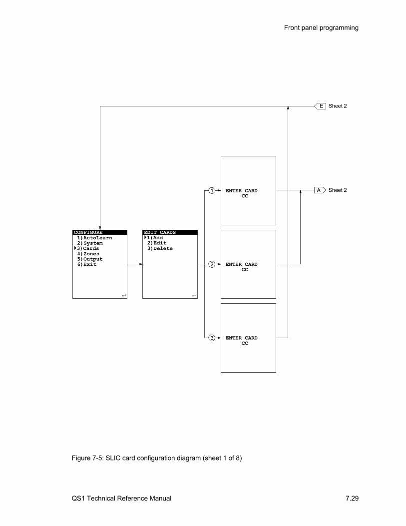
Front panel programming
QS1 Technical Reference Manual 7.29
CONFIGURE 1)AutoLearn 2)System3)Cards 4)Zones 5)Output 6)Exit
EDIT CARDS1)Add 2)Edit 3)Delete
E
Sheet 2AENTER CARD CC
ENTER CARD CC
ENTER CARD CC
Sheet 2
2
1
3
Figure 7-5: SLIC card configuration diagram (sheet 1 of 8)

Front panel programming
7.30 QS1 Technical Reference Manual
F Sheet 3
*Detectors :XXX*Modules :XXX
Enter : AcceptDelete : Cancel
*Detectors :XXX*Modules :XXX
Actual
Enter : AcceptDelete : Cancel
Expected
*Detectors :XXX*Modules :XXX
5
SLIC1)Config Card 2)Config Detect 3)Config Module 4)AutoLoop 5)Accept Map 6)Exit
ASheet 1
4
6 E Sheet 1
B
C
D
Sheet 3
Sheet 4
Sheet 4
1
2
3
Figure 7-5: SLIC card configuration diagram (sheet 2 of 8)
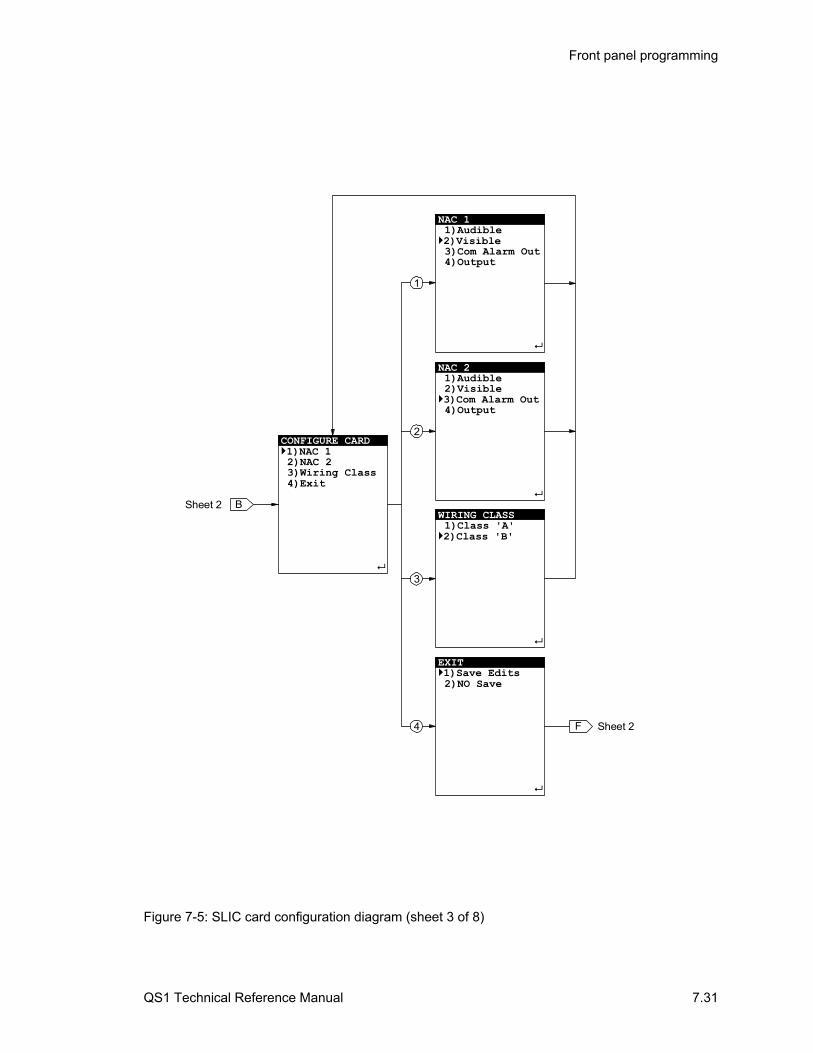
Front panel programming
QS1 Technical Reference Manual 7.31
NAC 1 1)Audible2)Visible3)Com Alarm Out
4)Output
NAC 2 1)Audible2)Visible3)Com Alarm Out 4)Output
WIRING CLASS 1)Class 'A'2)Class 'B'
EXIT 1)Save Edits 2)NO Save
2
1
3
BSheet 2
CONFIGURE CARD1)NAC 1 2)NAC 2 3)Wiring Class 4)Exit
4 F Sheet 2
Figure 7-5: SLIC card configuration diagram (sheet 3 of 8)
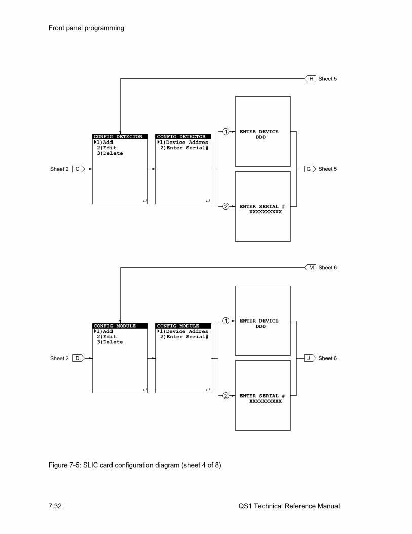
Front panel programming
7.32 QS1 Technical Reference Manual
C
CONFIG DETECTOR1)Add 2)Edit 3)Delete
CONFIG DETECTOR1)Device Addres 2)Enter Serial#
Sheet 2
2
1
ENTER DEVICE
DDD
ENTER SERIAL # XXXXXXXXXX
Sheet 5G
H Sheet 5
D
CONFIG MODULE1)Add 2)Edit 3)Delete
CONFIG MODULE 1)Device Addres 2)Enter Serial#
Sheet 2
2
1
ENTER DEVICE
DDD
ENTER SERIAL # XXXXXXXXXX
Sheet 6J
M Sheet 6
Figure 7-5: SLIC card configuration diagram (sheet 4 of 8)

Front panel programming
QS1 Technical Reference Manual 7.33
H Sheet 4
2
1
7
GSheet 4
CONFIG DETECTOR 1)Message 2)Model 3)Sensitivity 4)Verification 5)Pre-Alarm 6)Base Type 7)Exit
SENSITIVITY 1)Most 2)More 3)Normal 4)Less 5)Least
MODULE MODEL PS SD*END:COMPLETE*
VERIFICATION 1)None 2)12 seconds 3)24 seconds 4)36 seconds 5)48 seconds
PRE-ALARM 1)None 2)20% 3)40% 4)60% 5)80%
BASE TYPE 1)Standard 2)Relay3)Isolator
EXIT1)Save Edits 2)NO Save
4
3
6
5
ENTER TEXT (32)
Figure 7-5: SLIC card configuration diagram (sheet 5 of 8)
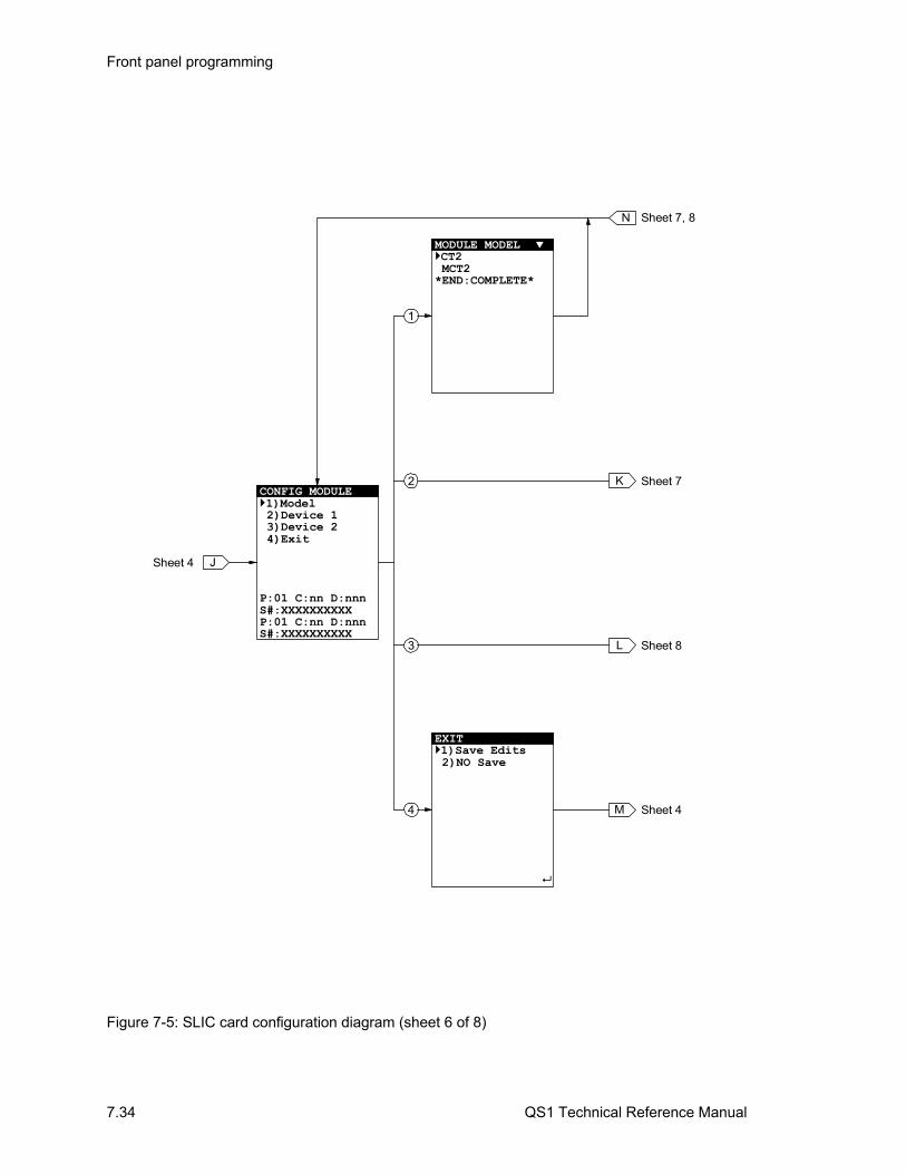
Front panel programming
7.34 QS1 Technical Reference Manual
MODULE MODEL CT2 MCT2*END:COMPLETE*
EXIT 1)Save Edits 2)NO Save
1
3
J
CONFIG MODULE 1)Model 2)Device 1 3)Device 2 4)Exit
XXXXXXXXXXP:01 C:nn D:nnnS#:XXXXXXXXXX
P:01 C:nn D:nnnS#:
Sheet 4
4 M Sheet 4
2
N Sheet 7, 8
K Sheet 7
L Sheet 8
Figure 7-5: SLIC card configuration diagram (sheet 6 of 8)
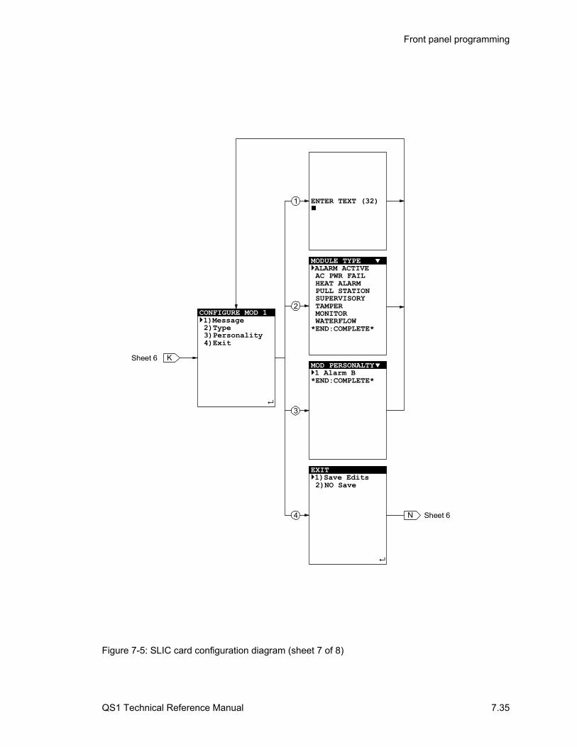
Front panel programming
QS1 Technical Reference Manual 7.35
ENTER TEXT (32)
EXIT 1)Save Edits 2)NO Save
1
3
KSheet 6
4 N Sheet 6
2CONFIGURE MOD 1 1)Message 2)Type 3)Personality 4)Exit
MODULE TYPE
AC PWR FAIL HEAT ALARM PULL STATION SUPERVISORY TAMPER MONITOR
ALARM ACTIVE
WATERFLOW*END:COMPLETE*
MOD PERSONALTY 1 Alarm B
*END:COMPLETE*
Figure 7-5: SLIC card configuration diagram (sheet 7 of 8)
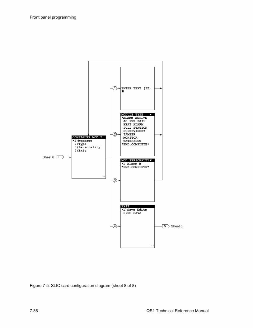
Front panel programming
7.36 QS1 Technical Reference Manual
ENTER TEXT (32)
EXIT 1)Save Edits 2)NO Save
1
3
LSheet 6
4 N Sheet 6
2CONFIGURE MOD 2 1)Message 2)Type 3)Personality 4)Exit
MODULE TYPE ALARM ACTIVE AC PWR FAIL HEAT ALARM PULL STATION SUPERVISORY TAMPER MONITOR WATERFLOW*END:COMPLETE*
MOD PERSONALTY 1 Alarm B*END:COMPLETE*
Figure 7-5: SLIC card configuration diagram (sheet 8 of 8)

Front panel programming
QS1 Technical Reference Manual 7.37
Configuring DLD cards To configure a DLD card, follow the procedure below. In addition, refer to Figure 7-6. DLD card options are described in Table 7-8.
Table 7-8: DLD card options
Option Description
#’s of CMS Determines the number of receivers to which the DLD card can send events
Possible values: 1 or 2
Default: 1
Rcvr 1 Prim # Designates the telephone number that you want the DLD card to use to call Receiver 1
Possible values: Up to 23 numeric characters. Do not include spaces.
Rcvr 1 Sec # Designates the telephone number that you want the DLD card to use to call Receiver 1 if it fails to connect to using the first telephone number
Possible values: Up to 23 numeric characters. Do not include spaces.
Rcvr 2 Prim # Designates the telephone number that you want the DLD card to use to call Receiver 2
Possible values: Up to 23 numeric characters. Do not include spaces.
Rcvr 2 Sec # Designates the telephone number that you want the DLD card to use to call Receiver 2 if it fails to connect to using the first telephone number
Possible values: Up to 23 numeric characters. Do not include spaces.
Retry Count Determines how many times the DLD card will attempt to call a receiver before indicating a trouble
Possible values: 05 to 10
Default: 05
Default alarm event messages
Determines the event activation and restoration codes sent to the central station for all alarm points that are not programmed to send event messages
Default: Blank
Default supervisory event messages
Determines the event activation and restoration codes sent to the central station for all supervisory points that are not programmed to send event messages
Default: Blank
Default trouble event messages
Determines the event activation and restoration codes sent to the central station for all points that are not programmed to send trouble event messages
Default: Blank

Front panel programming
7.38 QS1 Technical Reference Manual
To configure a DLD card:
1. On the Configure menu, choose Cards then on the Edit Cards menu:
• To configure a new DLD card, choose Add then enter the DLD card’s address (14)
• To configure an existing DLD card, choose Edit then enter the DLD card’s address (14)
• To delete a DLD card and return to the Configure menu, choose Delete then enter the DLD card’s address (14)
2. On the Dialer Setup menu:
• To change how many receivers you want the DLD card to call, choose #’s of CMS then on the Number Receive menu choose 1 or 2
• To enter the central station reciever telephone numbers. choose CMS Phone # then on the Phone Numbers menu:
Choose Rcvr 1 Prim # then enter the first telephone number for the first receiver.
Choose Rcvr 1 Sec # then enter the second telephone number for the first receiver.
Choose Rcvr 2 Prim # then enter the first telephone number for the second receiver.
Choose Rcvr 2 Sec # then enter the second telephone number for the second receiver.
Choose Exit to quit entering telephone numbers and return to the Dialer Setup menu.
• To change how many times you want the DLD card to attempt to call a receiver before indicating a trouble, choose Retry Count then enter a number from 5 to 10
• To configure receiver accounts, choose Accounts. For a detailed procedure see “Configuring receiver accounts” later in this chapter
• To enter default alarm, supervisory, and trouble event messages, choose Default Msgs
• To quit and return to the Configure menu, choose Exit then on the Exit menu:
Choose Save Edits to save your changes.
— or —
Choose NO Save to quit without saving your changes.
Front panel programming
QS1 Technical Reference Manual 7.39
3. On Default Msgs menu:
• To enter a default alarm event message, choose Alarm then on the MSG menu:
Choose Account, select the account where you want to send the event message from the list, then press Enter.
Choose Active Msg then enter the default event activation message.
Choose Restore Msg then enter the default event restoration message.
• To enter a default supervisory event message, choose Supervisory then perform the steps described above
• To enter a default trouble event message, choose Trouble then perform the steps described above
• To quit and return to the Default Msgs menu, choose Exit then on the Exit menu:
Choose Save Edits to save your changes.
— or —
Choose NO Save to quit without saving your changes.
Note: If you want the DLD card to use the predefined Contact ID strings when sending event messages to the default receiver account, do not enter values for the Active Msg and Restore Msg options.
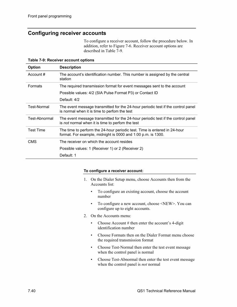
Front panel programming
7.40 QS1 Technical Reference Manual
Configuring receiver accounts To configure a receiver account, follow the procedure below. In addition, refer to Figure 7-6. Receiver account options are described in Table 7-9.
Table 7-9: Receiver account options
Option Description
Account # The account’s identification number. This number is assigned by the central station
Formats The required transmission format for event messages sent to the account
Possible values: 4/2 (SIA Pulse Format P3) or Contact ID
Default: 4/2
Test-Normal The event message transmitted for the 24-hour periodic test if the control panel is normal when it is time to perfom the test
Test-Abnormal The event message transmitted for the 24-hour periodic test if the control panel is not normal when it is time to perfom the test
Test Time The time to perform the 24-hour periodic test. Time is entered in 24-hour format. For example, midnight is 0000 and 1:00 p.m. is 1300.
CMS The receiver on which the account resides
Possible values: 1 (Receiver 1) or 2 (Receiver 2)
Default: 1
To configure a receiver account:
1. On the Dialer Setup menu, choose Accounts then from the Accounts list:
• To configure an existing account, choose the account number
• To configure a new account, choose <NEW>. You can configure up to eight accounts.
2. On the Accounts menu:
• Choose Account # then enter the account’s 4-digit identification number
• Choose Formats then on the Dialer Format menu choose the required transmission format
• Choose Test-Normal then enter the test event message when the control panel is normal
• Choose Test-Abnormal then enter the test event message when the control panel is not normal

Front panel programming
QS1 Technical Reference Manual 7.41
• Choose Test Time then enter the time that you want to perform the 24-hour periodic test
• Choose CMS then on the Number Receive menu choose the receiver on which the account resides
• Choose Exit to quit configuring an account and return to the Dialer Setup menu
To delete a receiver account:
1. On the Dialer Setup menu, choose Accounts then choose the account from the Accounts list
2. On the Accounts menu, choose Delete.
3. On the Exit menu:
Choose Save Edits delete the account and return to the Dialer Setup menu
— or —
Choose NO Save to return to the Dialer Setup menu without deleting the account
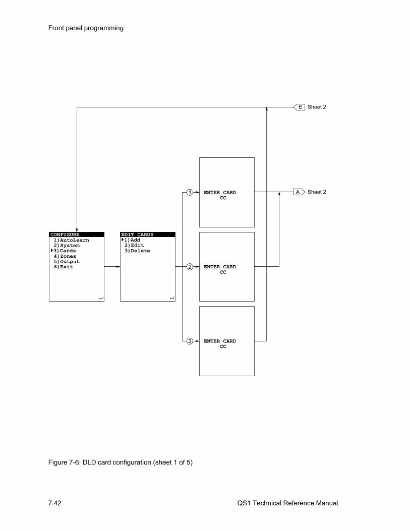
Front panel programming
7.42 QS1 Technical Reference Manual
CONFIGURE 1)AutoLearn 2)System3)Cards 4)Zones 5)Output 6)Exit
EDIT CARDS1)Add 2)Edit 3)Delete
E
Sheet 2AENTER CARD CC
ENTER CARD CC
ENTER CARD CC
Sheet 2
2
1
3
Figure 7-6: DLD card configuration (sheet 1 of 5)
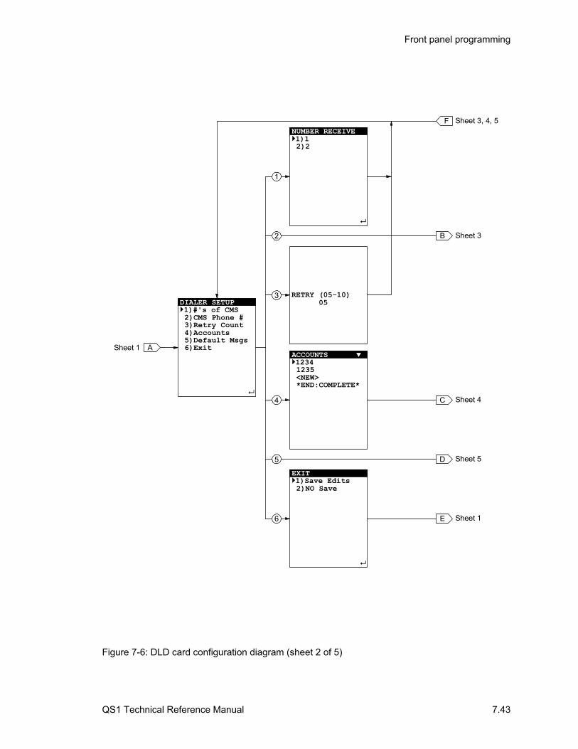
Front panel programming
QS1 Technical Reference Manual 7.43
FNUMBER RECEIVE1)1 2)2
Sheet 3, 4, 5
B Sheet 3
RETRY (05-10) 05
C Sheet 4
ACCOUNTS 1234 1235 <NEW>*END:COMPLETE*
EXIT 1)Save Edits 2)NO Save
4
DIALER SETUP1)#'s of CMS 2)CMS Phone # 3)Retry Count 4)Accounts 5)Default Msgs 6)Exit
ASheet 1
3
1
2
6 E Sheet 1
5 D Sheet 5
Figure 7-6: DLD card configuration diagram (sheet 2 of 5)
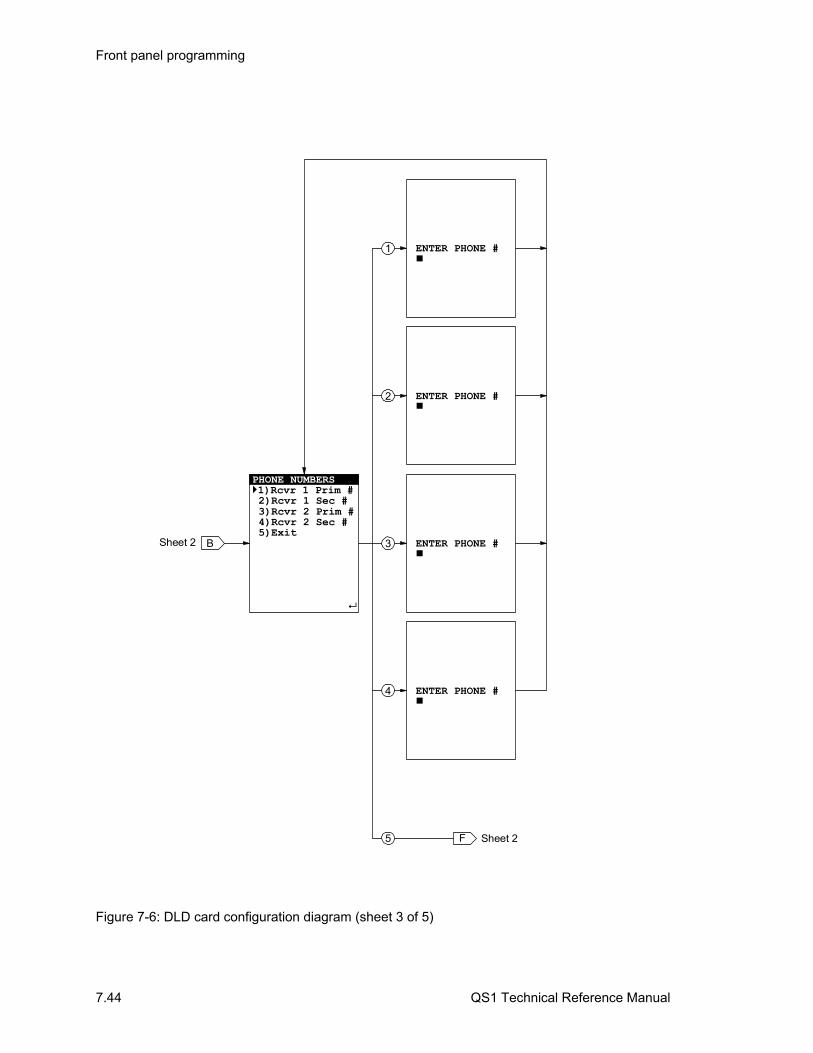
Front panel programming
7.44 QS1 Technical Reference Manual
ENTER PHONE #
ENTER PHONE #
ENTER PHONE #
ENTER PHONE #
PHONE NUMBERS1)Rcvr 1 Prim # 2)Rcvr 1 Sec # 3)Rcvr 2 Prim # 4)Rcvr 2 Sec # 5)Exit
BSheet 2 3
2
1
4
F Sheet 25
Figure 7-6: DLD card configuration diagram (sheet 3 of 5)

Front panel programming
QS1 Technical Reference Manual 7.45
CSheet 2
F Sheet 2
2
1
5
7
8
ACCOUNTS1)Account # 2)Formats 3)Test-Normal 4)Test-Abnormal 5)Test Time 6)CMS 7)Delete 8)Exit
ENTER ACCOUNT
0000
DIALER FORMAT 1)4/2 2)Contact ID
ENTER TST STNG XX
ENTER TST STNG XX
ENTER TEST TIME HHMM
NUMBER RECEIVE 1)1 2)2
EXIT1)Save Edits 2)NO Save
3
4
6
Figure 7-6: DLD card configuration diagram (sheet 4 of 5)
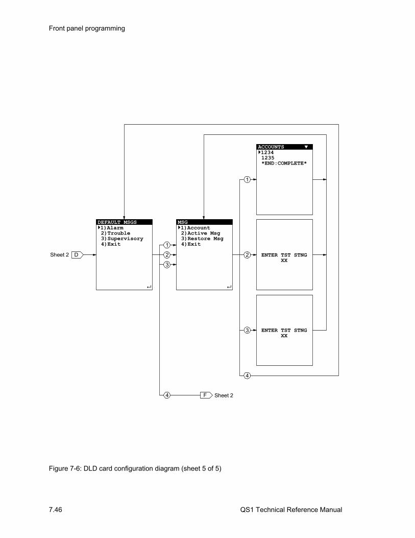
Front panel programming
7.46 QS1 Technical Reference Manual
DEFAULT MSGS 1)Alarm 2)Trouble 3)Supervisory 4)Exit
DSheet 2
MSG 1)Account 2)Active Msg3)Restore Msg
4)Exit
ENTER TST STNG XX
ENTER TST STNG XX
ACCOUNTS 1234 1235 *END:COMPLETE*
1
2
3
4
F Sheet 2
2
3
1
4
Figure 7-6: DLD card configuration diagram (sheet 5 of 5)

Front panel programming
QS1 Technical Reference Manual 7.47
Configuring output groups If you delete Output Group 249, you remove the active test response that Service Group 129 uses to briefly turn on notification appliances when performing a periodic system test. To reprogram the active test response you must use the software configuration utility.
If you delete Output Group 250, when the control panel enters the alarm state, the Visible device types detected when the default project database was created will not turn on. You will have to add these devices to another output group manually or use the software configuration utility.
You can only add 10 responses at a time before you must save your edits by exiting until you reach to the Configure menu.
Front panel programming only lets you add or remove active and trouble responses, for other response types you must use the configuration utility. For more information about response types, see “Before you begin” at the beginning of this chapter.
To configure an output group, follow the procedure below. In addition, refer to Figure 7-7.
To configure an output group:
1. On the Configure menu, choose Ouput then on the Edit Output menu:
• To configure a new output group, choose Add
• To configure an existing output group, choose Edit, select the output group from the list, then press Enter.
• To delete an output group and return to the Configure menu, choose Delete, select the output group from the list, press Enter, then on the Exit menu:
Choose Save Edits to save your changes.
— or —
Choose NO Save to quit without saving your changes.
2. On the Output Group menu:
• To add or remove responses, choose Responses then on the Output Type menu:
Choose Active to add or remove active responses.
Choose Fault to add or remove trouble responses.
• To view existing responses, choose Review then on the Output Type menu:
Choose Active for the set of active responses

Front panel programming
7.48 QS1 Technical Reference Manual
Choose Fault for the set of trouble responses
• To quit configuring an output group and return to the Configure menu, choose Exit then on the Exit menu:
Choose Save Edits to save your changes.
— or —
Choose NO Save to quit without saving your changes.
3. On the Output Responses menu:
• To add a response, choose Add
• To remove a response and return to the Output Group menu, choose Remove, select a response from the list, then press Enter
4. On the Response Type menu:
• To add a response that turns on an output (NAC, relay, or LED), choose Relay then enter the output’s device address
If the output is an addressable output, a response that turns the device on is automatically added for you.
If the device is a conventional output, on the Response Relay menu, choose a signal pattern (on, 20 bpm, 120 bpm, or temporal.)
On the Exit menu, choose Save Edits to save your changes and return to the Output Group menu
— or —
Choose NO Save to return to the Output Group menu without saving your changes
• To add a response that transmits an event message to a central station, choose Dialer, select the receiver account number, then press Enter.
• To add a response that adds a delay between other responses, choose Delay.
5. On the Response Dialer menu:
• To select when to transmit the event message, choose Send On then on the Send On menu:
Choose Activation to transmit the event message when a device is activated
Choose Restoration to transmit the event message when a device is restored
Note: To meet UL 864 requirements, you must program an activation response and a restoration response for each event.
Note: Front panel programming does not let you add a response that restores (turns off) an output.
Tip: Add all of the active responses first then all of the trouble responses. The order in which you add responses doesn’t matter except when delay responses are included.

Front panel programming
QS1 Technical Reference Manual 7.49
• To assign a priority to the event message, choose Priority then on the Priority menu:
Choose Life Safety to transmit the event message first. Life Safety is the highest priority and is typically assigned to alarm events.
Choose Property to transmit the event message second. Property is the next highest priority and is typically assigned to supervisory events.
Choose System Integr to transmit the event message last. System Integr(ity) is the lowest priority and is typically assigned to trouble events.
• To enter the event message’s content, choose String then enter the 2- or 9-digit number depending on the transmission format of the selected account
• To quit adding a dialer response and return to the Output Group menu, choose Exit then on the Exit menu:
Choose Save Edits to save your changes.
— or —
Choose NO Save to quit without saving your changes.
6. On the Response Delay menu:
• To select when to insert the delay, choose Delay Type then on the Delay Type menu:
Choose Act & Restore to insert the delay when a device is activated and when it is restored
Choose Activation to insert the delay only when a device is activated
Choose Restoration to insert the delay only when a device is restored
• To enter the amount of delay, choose Delay Time, then enter a time. The time is expressed in seconds. For example a 2-minute delay is 120 seconds.
• To quit adding a delay response and return to the Output Group menu, choose Exit then on the Exit menu:
Choose Save Edits to save your changes
— or —
Choose NO Save to quit without saving your changes
Note: To meet UL 864 requirements, assign the Life Safety priority only to dialer responses for alarm events, the Property priority only for Supervisory events, and the System Integrity priority only for trouble events.
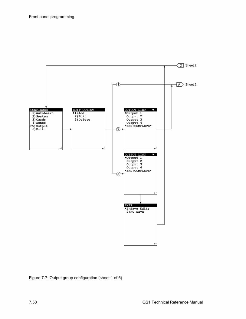
Front panel programming
7.50 QS1 Technical Reference Manual
CONFIGURE 1)AutoLearn 2)System 3)Cards 4)Zones5)Output 6)Exit
EDIT OUTPUT1)Add 2)Edit 3)Delete
D
Sheet 2A
2
3
1
OUTPUT LIST Output 1 Output 2 Output 3 Output 4*END:COMPLETE*
Sheet 2
EXIT1)Save Edits 2)NO Save
OUTPUT LIST Output 1 Output 2 Output 3 Output 4*END:COMPLETE*
Figure 7-7: Output group configuration (sheet 1 of 6)
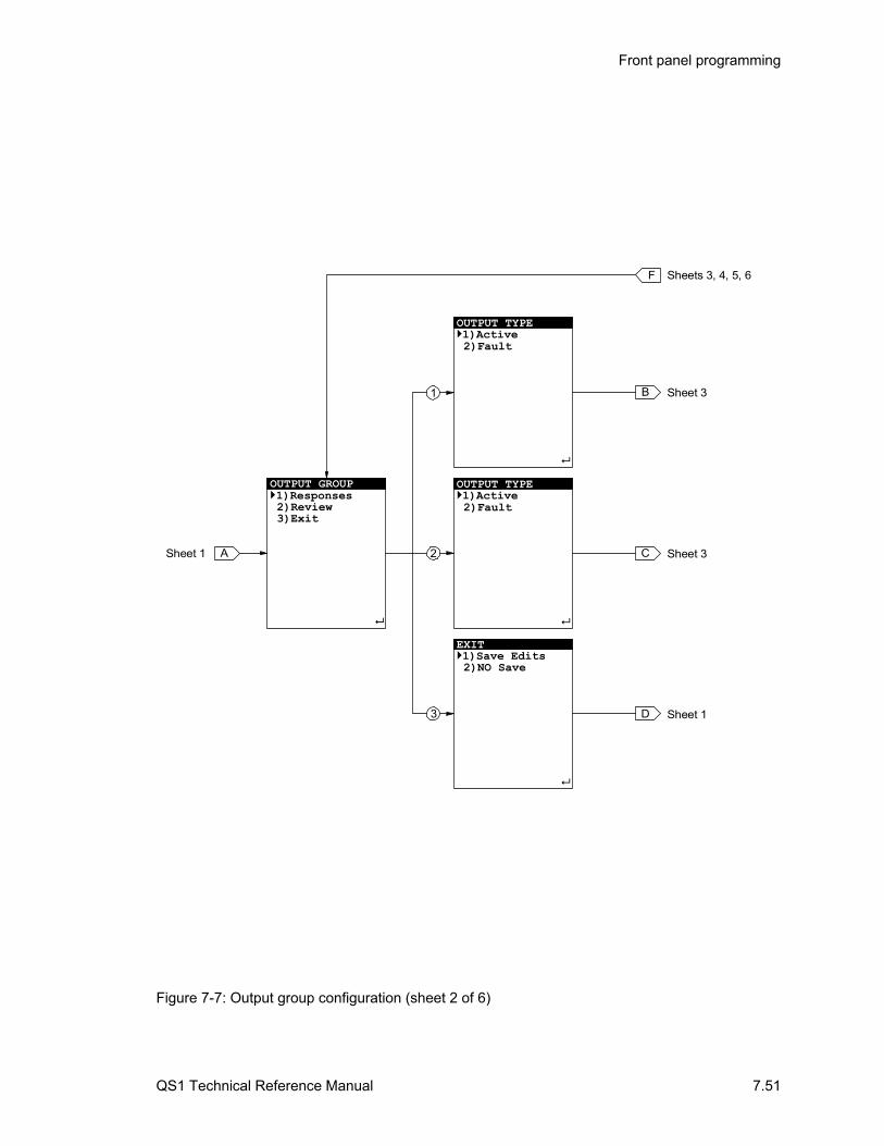
Front panel programming
QS1 Technical Reference Manual 7.51
OUTPUT TYPE1)Active 2)Fault
OUTPUT GROUP1)Responses 2)Review 3)Exit
ASheet 1
Sheet 3B
2
3
1
EXIT1)Save Edits 2)NO Save
OUTPUT TYPE1)Active 2)Fault
Sheet 3C
F Sheets 3, 4, 5, 6
Sheet 1D
Figure 7-7: Output group configuration (sheet 2 of 6)

Front panel programming
7.52 QS1 Technical Reference Manual
1
2
OUTPUT RESPONS P01C01D015 BALSP01C01D016 BALS
Delay:0030 A*END:COMPLETE*
B
OUTPUT RESPONSES1)Add 2)Remove
Sheet 2
OUTPUT RESPONS P01C01D015 BALSP01C01D016 BALS
Delay:0030 A*END:COMPLETE*
CSheet 2
G Sheet 4
F Sheet 2
Figure 7-7: Output group configuration (sheet 3 of 6)
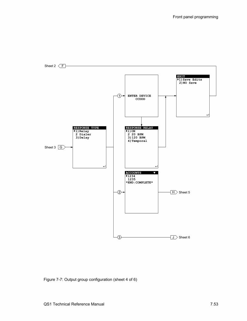
Front panel programming
QS1 Technical Reference Manual 7.53
3
2
ENTER DEVICE
CCDDD
1
RESPONSE RELAY 1)ON 2 20 BPM 3)120 BPM 4)Temporal
J Sheet 6
FSheet 2
H Sheet 5
ACCOUNTS 1234 1235*END:COMPLETE*
EXIT1)Save Edits 2)NO Save
GSheet 3
RESPONSE TYPE1)Relay 2 Dialer 3)Delay
Figure 7-7: Output group configuration (sheet 4 of 6)
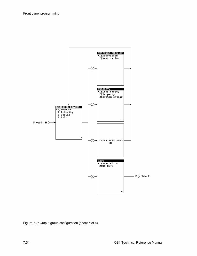
Front panel programming
7.54 QS1 Technical Reference Manual
RESPONSE SEND ON1)Activation 2)Restoration
2
3
1
PRIORITY1)Life Safety 2)Property3)System Integr
ENTER TEST STNG XX
RESPONSE DIALER 1)Send On 2)Priority 3)String 4)Exit
HSheet 4
EXIT1)Save Edits 2)NO Save
4 F Sheet 2
Figure 7-7: Output group configuration (sheet 5 of 6)

Front panel programming
QS1 Technical Reference Manual 7.55
RESPONSE DELAY 1)Delay Type 2)Delay Time 3)Exit
JSheet 4
DELAY TYPE1)Act & Restore 2)Activation 3)Restoration
2
3
1
EXIT1)Save Edits 2)NO Save
ENTER TIME 0000
F Sheet 2
Figure 7-7: Output group configuration (sheet 6 of 6)
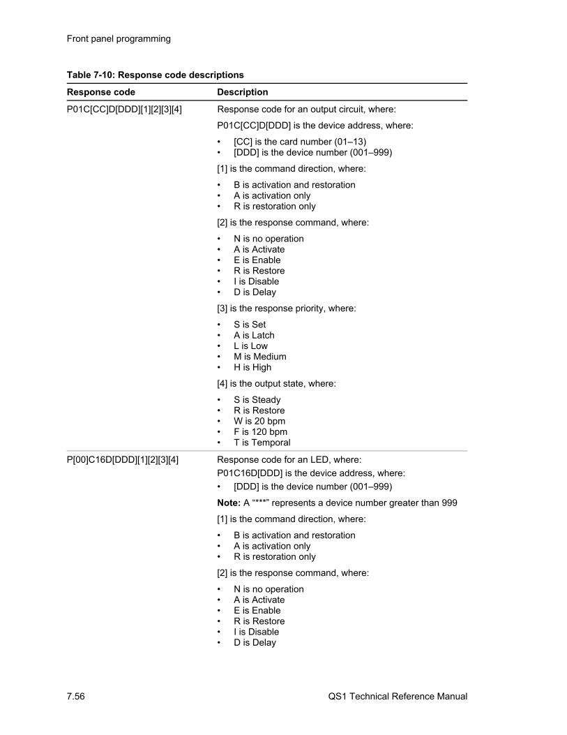
Front panel programming
7.56 QS1 Technical Reference Manual
Table 7-10: Response code descriptions
Response code Description
P01C[CC]D[DDD][1][2][3][4] Response code for an output circuit, where:
P01C[CC]D[DDD] is the device address, where:
• [CC] is the card number (01–13) • [DDD] is the device number (001–999)
[1] is the command direction, where:
• B is activation and restoration • A is activation only • R is restoration only
[2] is the response command, where:
• N is no operation • A is Activate • E is Enable • R is Restore • I is Disable • D is Delay
[3] is the response priority, where:
• S is Set • A is Latch • L is Low • M is Medium • H is High
[4] is the output state, where:
• S is Steady • R is Restore • W is 20 bpm • F is 120 bpm • T is Temporal
P[00]C16D[DDD][1][2][3][4] Response code for an LED, where:
P01C16D[DDD] is the device address, where:
• [DDD] is the device number (001–999)
Note: A “***” represents a device number greater than 999
[1] is the command direction, where:
• B is activation and restoration • A is activation only • R is restoration only
[2] is the response command, where:
• N is no operation • A is Activate • E is Enable • R is Restore • I is Disable • D is Delay
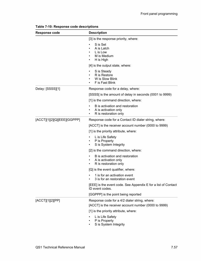
Front panel programming
QS1 Technical Reference Manual 7.57
Table 7-10: Response code descriptions
Response code Description
[3] is the response priority, where:
• S is Set • A is Latch • L is Low • M is Medium • H is High
[4] is the output state, where:
• S is Steady • R is Restore • W is Slow Blink • F is Fast Blink
Delay: [SSSS][1] Response code for a delay, where:
[SSSS[ is the amount of delay in seconds (0001 to 9999)
[1] is the command direction, where:
• B is activation and restoration • A is activation only • R is restoration only
[ACCT][1][2][Q][EEE][GGPPP] Response code for a Contact ID dialer string, where:
[ACCT] is the receiver account number (0000 to 9999)
[1] is the priority attribute, where:
• L is Life Safety • P is Property • S is System Integrity
[2] is the command direction, where:
• B is activation and restoration • A is activation only • R is restoration only
[Q] is the event qualifier, where:
• 1 is for an activation event • 3 is for an restoration event
[EEE] is the event code. See Appendix E for a list of Contact ID event codes.
[GGPPP] is the point being reported
[ACCT][1][2][PP] Response code for a 4/2 dialer string, where:
[ACCT] is the receiver account number (0000 to 9999)
[1] is the priority attribute, where:
• L is Life Safety • P is Property • S is System Integrity
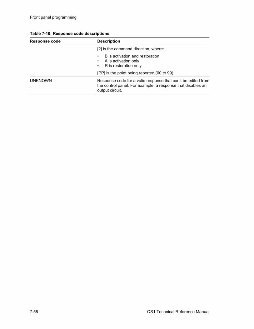
Front panel programming
7.58 QS1 Technical Reference Manual
Table 7-10: Response code descriptions
Response code Description
[2] is the command direction, where:
• B is activation and restoration • A is activation only • R is restoration only
[PP] is the point being reported (00 to 99)
UNKNOWN Response code for a valid response that can’t be edited from the control panel. For example, a response that disables an output circuit.
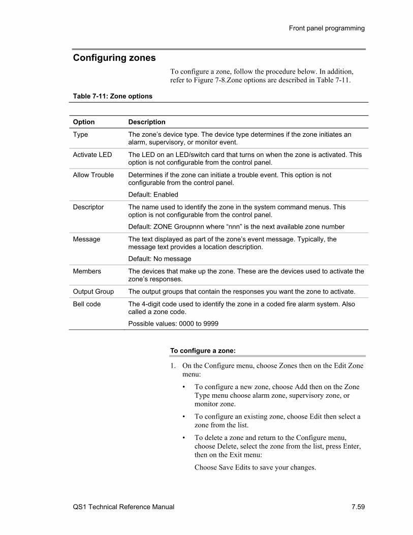
Front panel programming
QS1 Technical Reference Manual 7.59
Configuring zones To configure a zone, follow the procedure below. In addition, refer to Figure 7-8.Zone options are described in Table 7-11.
Table 7-11: Zone options
Option Description
Type The zone’s device type. The device type determines if the zone initiates an alarm, supervisory, or monitor event.
Activate LED The LED on an LED/switch card that turns on when the zone is activated. This option is not configurable from the control panel.
Allow Trouble Determines if the zone can initiate a trouble event. This option is not configurable from the control panel.
Default: Enabled
Descriptor The name used to identify the zone in the system command menus. This option is not configurable from the control panel.
Default: ZONE Groupnnn where “nnn” is the next available zone number
Message The text displayed as part of the zone’s event message. Typically, the message text provides a location description.
Default: No message
Members The devices that make up the zone. These are the devices used to activate the zone’s responses.
Output Group The output groups that contain the responses you want the zone to activate.
Bell code The 4-digit code used to identify the zone in a coded fire alarm system. Also called a zone code.
Possible values: 0000 to 9999
To configure a zone:
1. On the Configure menu, choose Zones then on the Edit Zone menu:
• To configure a new zone, choose Add then on the Zone Type menu choose alarm zone, supervisory zone, or monitor zone.
• To configure an existing zone, choose Edit then select a zone from the list.
• To delete a zone and return to the Configure menu, choose Delete, select the zone from the list, press Enter, then on the Exit menu:
Choose Save Edits to save your changes.

Front panel programming
7.60 QS1 Technical Reference Manual
— or —
Choose NO Save to quit without saving your changes.
2. On the Zone Edit menu:
• To enter the text for the zone’s event message, choose Message. To enter text you must use a compatible bar code scanner.
• To designate which devices are members of the zone, choose Members then on the Zone Members menu:
Choose Device Addres then enter the device’s address number to add it to the zone member list.
Choose Delete, select a device address from the zone list then press enter to delete a member.
Choose Review to view a list of current zone members.
Press the Del button to return to the Zone Edit menu.
• To correlate output groups to the zone, choose Output Group then on the Output Group menu:
Choose Add, select an output group from the list, then press Enter to assign it to the zone.
Choose Remove, select an output group from the list then press Enter to unassign an output group.
Choose Review to view a list of output groups currently assigned to the zone.
Press the Del button to return to the Zone Edit menu.
• To enter a bell code, choose Coding then enter the 4-digit code used to identify the zone
• To change the zone’s device type, choose Type then on the Zone Type menu choose a zone type.
• To quit and return to the Configure menu, choose Exit then on the Exit menu:
Choose Save Edits to save your changes.
— or —
Choose NO Save to quit without saving your changes.
Caution: The zone type option determines which devices can be zone members. Changing the zone type after you have added members to the zone automatically removes the members from the zone.
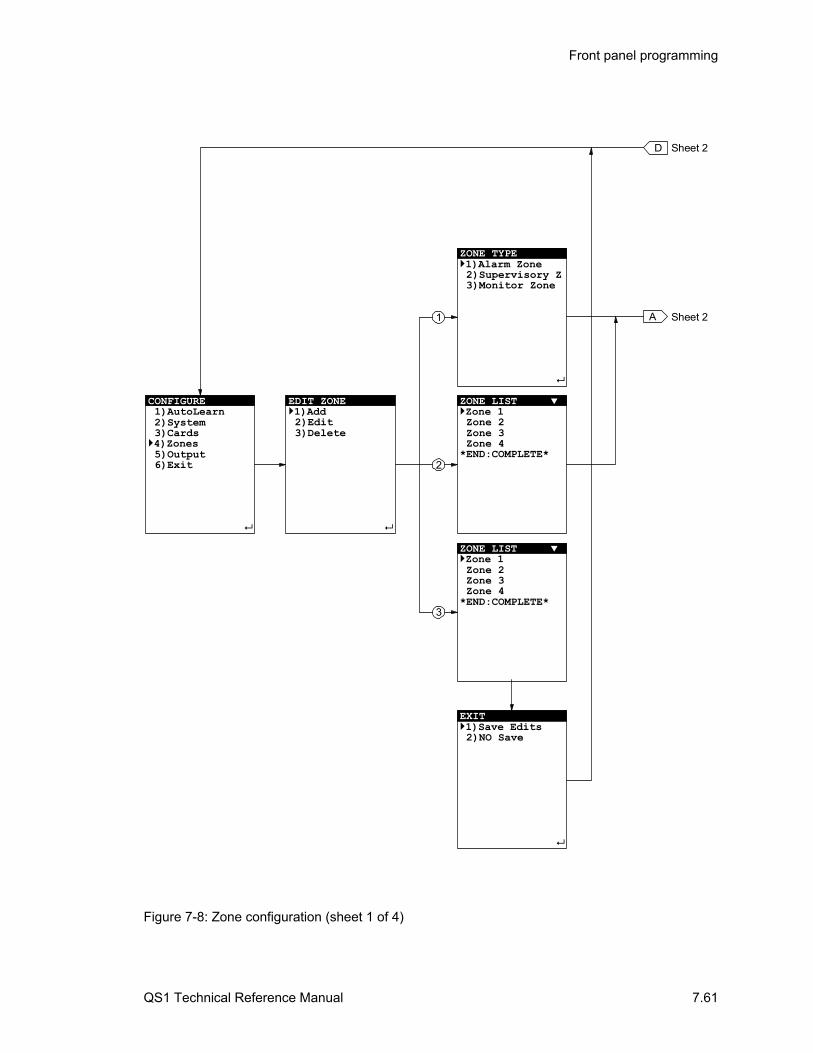
Front panel programming
QS1 Technical Reference Manual 7.61
CONFIGURE 1)AutoLearn 2)System 3)Cards4)Zones 5)Output 6)Exit
EDIT ZONE1)Add 2)Edit 3)Delete
D
Sheet 2A
2
3
1
ZONE TYPE1)Alarm Zone2)Supervisory Z
3)Monitor Zone
ZONE LIST Zone 1 Zone 2 Zone 3 Zone 4*END:COMPLETE*
ZONE LIST Zone 1 Zone 2 Zone 3 Zone 4*END:COMPLETE*
Sheet 2
EXIT1)Save Edits 2)NO Save
Figure 7-8: Zone configuration (sheet 1 of 4)

Front panel programming
7.62 QS1 Technical Reference Manual
B
1
3
2
CODED MSG (4) XXXX
4
ZONE TYPE1)Alarm Zone2)Supervisory Z
3)Monitor Zone
5
C
EXIT1)Save Edits 2)NO Save
6
ZONE EDIT1)Message 2)Members 3)Output Group 4)Coding 5)Type 6)Exit
ASheet 1
Sheet 3
Sheet 4
D Sheet 1
Figure 7-8: Zone configuration (sheet 2 of 4)
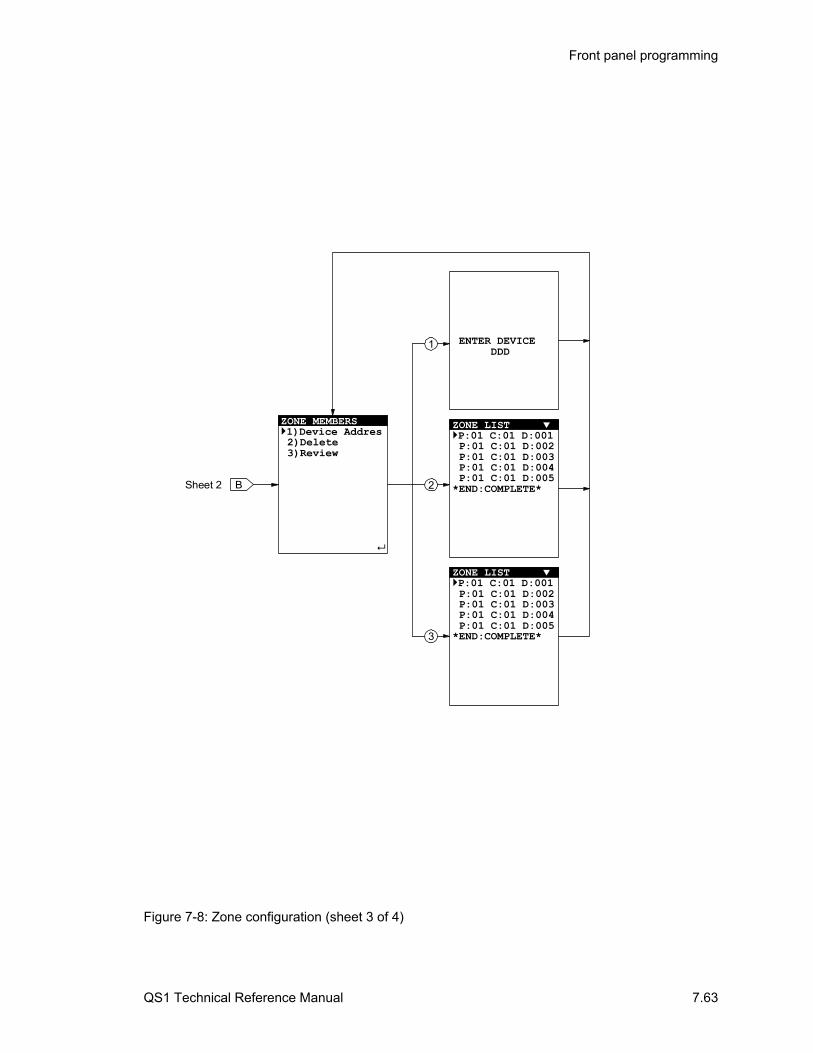
Front panel programming
QS1 Technical Reference Manual 7.63
1
3
B 2
ZONE MEMBERS1)Device Addres 2)Delete 3)Review
ENTER DEVICE
DDD
ZONE LIST P:01 C:01 D:001P:01 C:01 D:002P:01 C:01 D:003P:01 C:01 D:004P:01 C:01 D:005
*END:COMPLETE*
ZONE LIST P:01 C:01 D:001P:01 C:01 D:002P:01 C:01 D:003P:01 C:01 D:004P:01 C:01 D:005
*END:COMPLETE*
Sheet 2
Figure 7-8: Zone configuration (sheet 3 of 4)
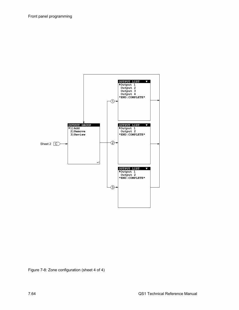
Front panel programming
7.64 QS1 Technical Reference Manual
C
OUTPUT GROUP1)Add 2)Remove 3)Review
OUTPUT LIST Output 1 Output 2 Output 3 Output 4*END:COMPLETE*
OUTPUT LIST Output 1 Output 2*END:COMPLETE*
OUTPUT LIST Output 1 Output 2*END:COMPLETE*
Sheet 2
1
3
2
Figure 7-8: Zone configuration (sheet 4 of 4)
Front panel programming
QS1 Technical Reference Manual 7.65
Clearing the history log Use the Clear History command on the Program menu to clear the history log and reset the alarm history counter to zero (0000). The alarm history counter keeps track of how many times the control panel has entered the alarm condition.
To clear the history log:
1. Log on using the level 4 password.
2. From the main menu, choose Program, then Clear History.
3. Enter the panel number of the control panel whose history log you want cleared.

Front panel programming
7.66 QS1 Technical Reference Manual
Saving the project database After you finish making all of your programming changes, exit the Configure menu to save your changes and update the project database. Use the Save command on the Update Databases menu to save the project database only in the control panel. Use the Save & Sync command to save the project database in the control panel and automatically update the project database in all of the remote annunciators.
You must also save the project database after adding eight responses to an output group.
Tip: Depending on the size of the system, updating the project database across remote annunciators may take several minutes. Use the Save & Sync command only after the system has been completely tested.
To save the project database:
1. On the Configure menu, choose Exit.
2. On the Update Database menu, choose one of the following:
• Save to save the control panel database
• Save & Sync to save the control panel database and update all of the remote annunciators
QS1 Technical Reference Manual 8.1
Chapter 8 Service and troubleshooting
Summary
This chapter provides instructions for servicing and troubleshooting the fire alarm system. It is intended for those trained and authorized to maintain the fire alarm system.
Content
Display or print a revision report • 8.2 Starting and canceling a service group test • 8.3 Disabling and enabling AND groups • 8.4 Disabling and enabling matrix groups • 8.5 Disabling and enabling time controls • 8.6 Disabling and enabling switches • 8.7 Disabling and enabling option cards • 8.8 Turning an output on and off • 8.9 Turning an LED on and off • 8.11 Setting the system time and date • 8.13 Changing the level 2 password • 8.14 Clearing trouble messages • 8.15 Replacing the control panel fuse • 8.20 Using HyperTerminal • 8.21
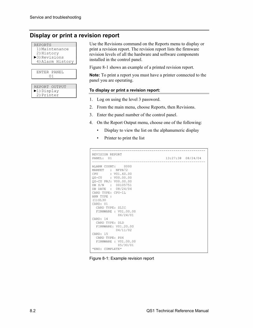
Service and troubleshooting
8.2 QS1 Technical Reference Manual
Display or print a revision report Use the Revisions command on the Reports menu to display or print a revision report. The revision report lists the firmware revision levels of all the hardware and software components installed in the control panel.
Figure 8-1 shows an example of a printed revision report.
Note: To print a report you must have a printer connected to the panel you are operating.
To display or print a revision report:
1. Log on using the level 3 password.
2. From the main menu, choose Reports, then Revisions.
3. Enter the panel number of the control panel.
4. On the Report Output menu, choose one of the following:
• Display to view the list on the alphanumeric display
• Printer to print the list
---------------------------------------------------------REVISION REPORTPANEL: 01 13:27:38 08/24/04
---------------------------------------------------------ALARM COUNT: 0000MARKET : NFPA72CPU : V01.60.00QS-CU : V00.00.00QS-CU PRJ: V00.00.00DB S/N : 00105751DB DATE : 08/24/04CARD TYPE: CPU-1LANN TYPE :(1)SL30CARD: 01 CARD TYPE: SLIC FIRMWARE : V01.00.00 06/24/01CARD: 14 CARD TYPE: DLD FIRMWARE: V01.20.00 04/11/02CARD: 15 CARD TYPE: PS6 FIRMWARE : V01.00.00 05/30/01*END: COMPLETE*
Figure 8-1: Example revision report
REPORTS 1)Maintenance 2)History 3)Revisions 4)Alarm History
ENTER PANEL 01
REPORT OUTPUT 1)Display 2)Printer
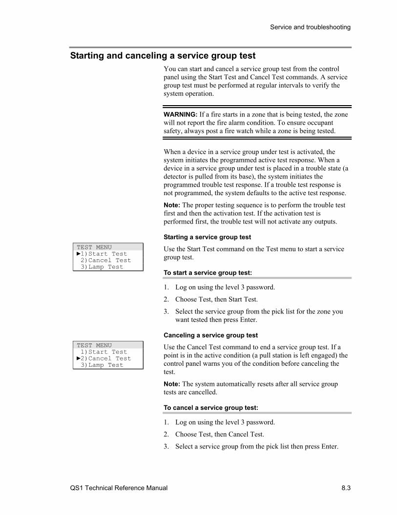
Service and troubleshooting
QS1 Technical Reference Manual 8.3
Starting and canceling a service group test You can start and cancel a service group test from the control panel using the Start Test and Cancel Test commands. A service group test must be performed at regular intervals to verify the system operation.
WARNING: If a fire starts in a zone that is being tested, the zone will not report the fire alarm condition. To ensure occupant safety, always post a fire watch while a zone is being tested.
When a device in a service group under test is activated, the system initiates the programmed active test response. When a device in a service group under test is placed in a trouble state (a detector is pulled from its base), the system initiates the programmed trouble test response. If a trouble test response is not programmed, the system defaults to the active test response.
Note: The proper testing sequence is to perform the trouble test first and then the activation test. If the activation test is performed first, the trouble test will not activate any outputs.
Starting a service group test
Use the Start Test command on the Test menu to start a service group test.
To start a service group test:
1. Log on using the level 3 password.
2. Choose Test, then Start Test.
3. Select the service group from the pick list for the zone you want tested then press Enter.
Canceling a service group test
Use the Cancel Test command to end a service group test. If a point is in the active condition (a pull station is left engaged) the control panel warns you of the condition before canceling the test.
Note: The system automatically resets after all service group tests are cancelled.
To cancel a service group test:
1. Log on using the level 3 password.
2. Choose Test, then Cancel Test.
3. Select a service group from the pick list then press Enter.
TEST MENU 1)Start Test 2)Cancel Test 3)Lamp Test
TEST MENU 1)Start Test 2)Cancel Test 3)Lamp Test
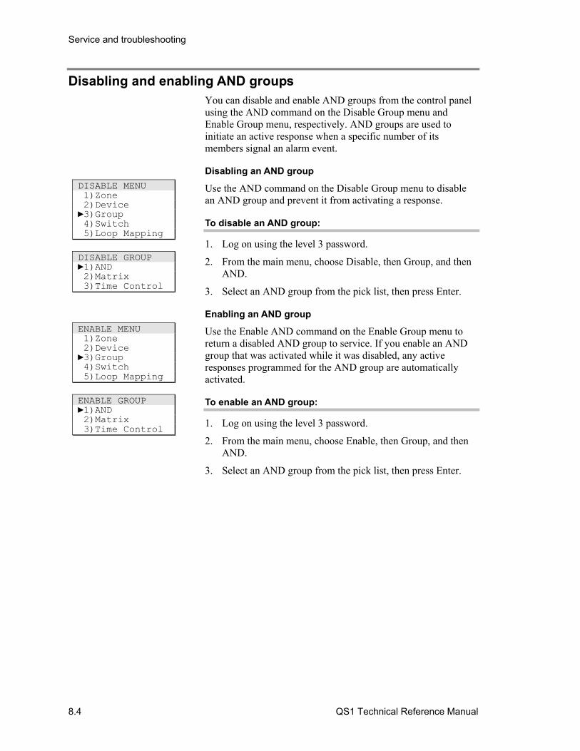
Service and troubleshooting
8.4 QS1 Technical Reference Manual
Disabling and enabling AND groups You can disable and enable AND groups from the control panel using the AND command on the Disable Group menu and Enable Group menu, respectively. AND groups are used to initiate an active response when a specific number of its members signal an alarm event.
Disabling an AND group
Use the AND command on the Disable Group menu to disable an AND group and prevent it from activating a response.
To disable an AND group:
1. Log on using the level 3 password.
2. From the main menu, choose Disable, then Group, and then AND.
3. Select an AND group from the pick list, then press Enter.
Enabling an AND group
Use the Enable AND command on the Enable Group menu to return a disabled AND group to service. If you enable an AND group that was activated while it was disabled, any active responses programmed for the AND group are automatically activated.
To enable an AND group:
1. Log on using the level 3 password.
2. From the main menu, choose Enable, then Group, and then AND.
3. Select an AND group from the pick list, then press Enter.
DISABLE MENU 1)Zone 2)Device 3)Group 4)Switch 5)Loop Mapping
DISABLE GROUP 1)AND 2)Matrix 3)Time Control
ENABLE MENU 1)Zone 2)Device 3)Group 4)Switch 5)Loop Mapping
ENABLE GROUP 1)AND 2)Matrix 3)Time Control
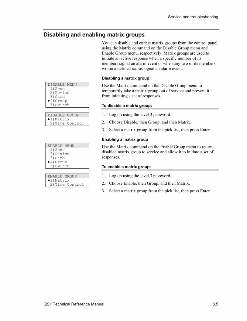
Service and troubleshooting
QS1 Technical Reference Manual 8.5
Disabling and enabling matrix groups You can disable and enable matrix groups from the control panel using the Matrix command on the Disable Group menu and Enable Group menu, respectively. Matrix groups are used to initiate an active response when a specific number of its members signal an alarm event or when any two of its members within a defined radius signal an alarm event.
Disabling a matrix group
Use the Matrix command on the Disable Group menu to temporarily take a matrix group out of service and prevent it from initiating a set of responses.
To disable a matrix group:
1. Log on using the level 3 password.
2. Choose Disable, then Group, and then Matrix.
3. Select a matrix group from the pick list, then press Enter.
Enabling a matrix group
Use the Matrix command on the Enable Group menu to return a disabled matrix group to service and allow it to initiate a set of responses.
To enable a matrix group:
1. Log on using the level 3 password.
2. Choose Enable, then Group, and then Matrix.
3. Select a matrix group from the pick list, then press Enter.
DISABLE MENU 1)Zone 2)Device 3)Card 4)Group 5)Switch
DISABLE GROUP 1)Matrix 2)Time Control
ENABLE MENU 1)Zone 2)Device 3)Card 4)Group 5)Switch
ENABLE GROUP 1)Matrix 2)Time Control
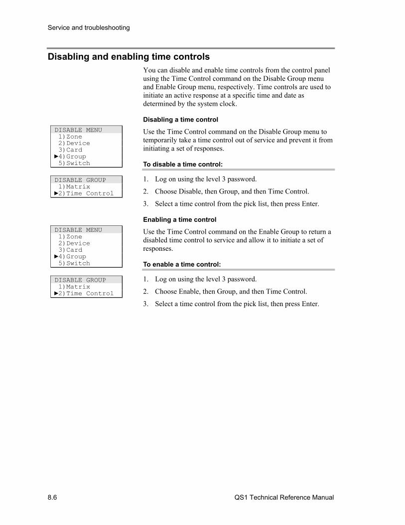
Service and troubleshooting
8.6 QS1 Technical Reference Manual
Disabling and enabling time controls You can disable and enable time controls from the control panel using the Time Control command on the Disable Group menu and Enable Group menu, respectively. Time controls are used to initiate an active response at a specific time and date as determined by the system clock.
Disabling a time control
Use the Time Control command on the Disable Group menu to temporarily take a time control out of service and prevent it from initiating a set of responses.
To disable a time control:
1. Log on using the level 3 password.
2. Choose Disable, then Group, and then Time Control.
3. Select a time control from the pick list, then press Enter.
Enabling a time control
Use the Time Control command on the Enable Group to return a disabled time control to service and allow it to initiate a set of responses.
To enable a time control:
1. Log on using the level 3 password.
2. Choose Enable, then Group, and then Time Control.
3. Select a time control from the pick list, then press Enter.
DISABLE MENU 1)Zone 2)Device 3)Card 4)Group 5)Switch
DISABLE GROUP 1)Matrix 2)Time Control
DISABLE MENU 1)Zone 2)Device 3)Card 4)Group 5)Switch
DISABLE GROUP 1)Matrix 2)Time Control
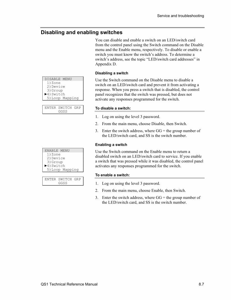
Service and troubleshooting
QS1 Technical Reference Manual 8.7
Disabling and enabling switches You can disable and enable a switch on an LED/switch card from the control panel using the Switch command on the Disable menu and the Enable menu, respectively. To disable or enable a switch you must know the switch’s address. To determine a switch’s address, see the topic “LED/switch card addresses” in Appendix D.
Disabling a switch
Use the Switch command on the Disable menu to disable a switch on an LED/switch card and prevent it from activating a response. When you press a switch that is disabled, the control panel recognizes that the switch was pressed, but does not activate any responses programmed for the switch.
To disable a switch:
1. Log on using the level 3 password.
2. From the main menu, choose Disable, then Switch.
3. Enter the switch address, where GG = the group number of the LED/switch card, and SS is the switch number.
Enabling a switch
Use the Switch command on the Enable menu to return a disabled switch on an LED/switch card to service. If you enable a switch that was pressed while it was disabled, the control panel activates any responses programmed for the switch.
To enable a switch:
1. Log on using the level 3 password.
2. From the main menu, choose Enable, then Switch.
3. Enter the switch address, where GG = the group number of the LED/switch card, and SS is the switch number.
DISABLE MENU 1)Zone 2)Device 3)Group 4)Switch 5)Loop Mapping
ENTER SWITCH GRP GGSS
ENABLE MENU 1)Zone 2)Device 3)Group 4)Switch 5)Loop Mapping
ENTER SWITCH GRP GGSS

Service and troubleshooting
8.8 QS1 Technical Reference Manual
Disabling and enabling option cards You can disable and enable option cards from the control panel using the Card command on the Disable menu and Enable menu, respectively. To disable or enable an option card you must know the card’s card address.
Note: If you disable an option card with notification appliance circuits (NACs) configured as common alarm outputs and there is an alarm event, the NACs will briefly turn on an off approximately twice a minute. This is normal.
Disabling an option card
Use the Card command on the Disable menu to disable an option card and prevent it from activating any responses.
To disable an option card:
1. Log on using the level 4 password.
2. From the main menu, choose Disable, then Card.
3. Enter the card number, where: PP = 01, and CC = the card number.
Enabling an option card
Use the Card command on the Enable menu to return a disabled option card to service.
To enable an option card:
1. Log on using the level 4 password.
2. From the main menu, choose Enable, then Card.
3. Enter the card number, where: PP = 01, and CC = the card number.
DISABLE 1)Zone 2)Device 3)Card 4)Group 5)Switch 6)Loop Mapping
ENTER CARD 01CC
ENABLE 1)Zone 2)Device 3)Card 4)Group 5)Switch 6)Loop Mapping
ENTER CARD 01CC
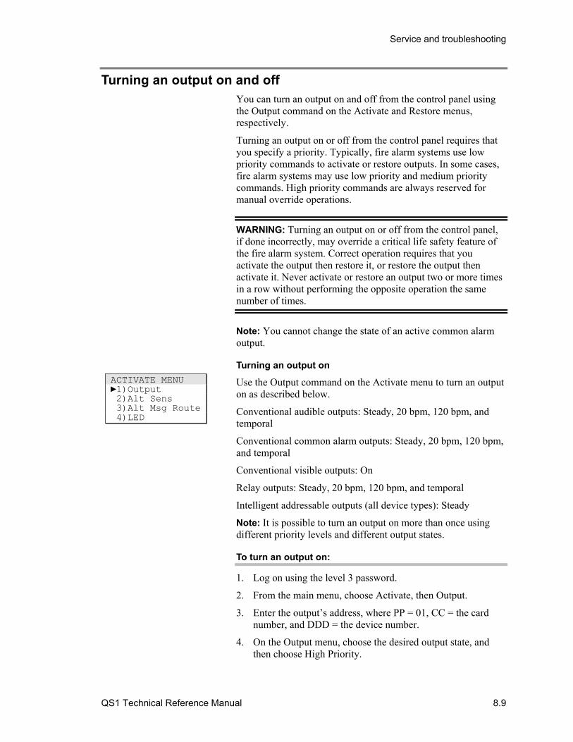
Service and troubleshooting
QS1 Technical Reference Manual 8.9
Turning an output on and off You can turn an output on and off from the control panel using the Output command on the Activate and Restore menus, respectively.
Turning an output on or off from the control panel requires that you specify a priority. Typically, fire alarm systems use low priority commands to activate or restore outputs. In some cases, fire alarm systems may use low priority and medium priority commands. High priority commands are always reserved for manual override operations.
WARNING: Turning an output on or off from the control panel, if done incorrectly, may override a critical life safety feature of the fire alarm system. Correct operation requires that you activate the output then restore it, or restore the output then activate it. Never activate or restore an output two or more times in a row without performing the opposite operation the same number of times.
Note: You cannot change the state of an active common alarm output.
Turning an output on
Use the Output command on the Activate menu to turn an output on as described below.
Conventional audible outputs: Steady, 20 bpm, 120 bpm, and temporal
Conventional common alarm outputs: Steady, 20 bpm, 120 bpm, and temporal
Conventional visible outputs: On
Relay outputs: Steady, 20 bpm, 120 bpm, and temporal
Intelligent addressable outputs (all device types): Steady
Note: It is possible to turn an output on more than once using different priority levels and different output states.
To turn an output on:
1. Log on using the level 3 password.
2. From the main menu, choose Activate, then Output.
3. Enter the output’s address, where PP = 01, CC = the card number, and DDD = the device number.
4. On the Output menu, choose the desired output state, and then choose High Priority.
ACTIVATE MENU 1)Output 2)Alt Sens 3)Alt Msg Route 4)LED
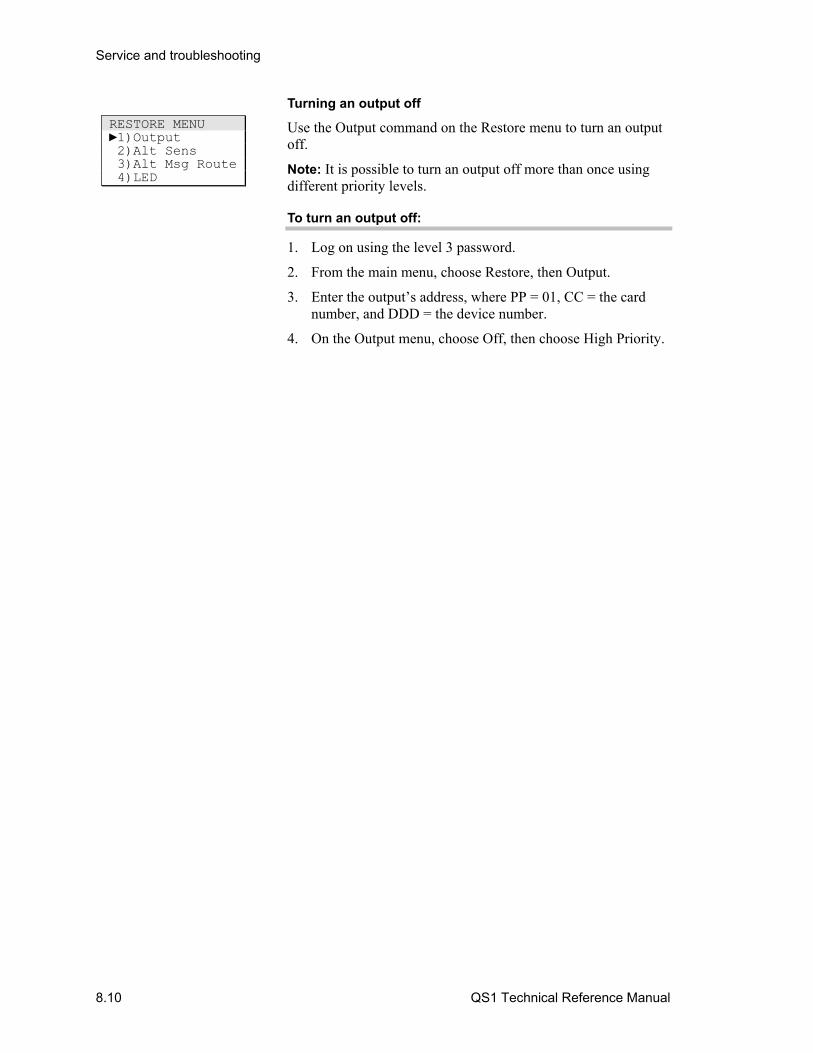
Service and troubleshooting
8.10 QS1 Technical Reference Manual
Turning an output off
Use the Output command on the Restore menu to turn an output off.
Note: It is possible to turn an output off more than once using different priority levels.
To turn an output off:
1. Log on using the level 3 password.
2. From the main menu, choose Restore, then Output.
3. Enter the output’s address, where PP = 01, CC = the card number, and DDD = the device number.
4. On the Output menu, choose Off, then choose High Priority.
RESTORE MENU 1)Output 2)Alt Sens 3)Alt Msg Route 4)LED
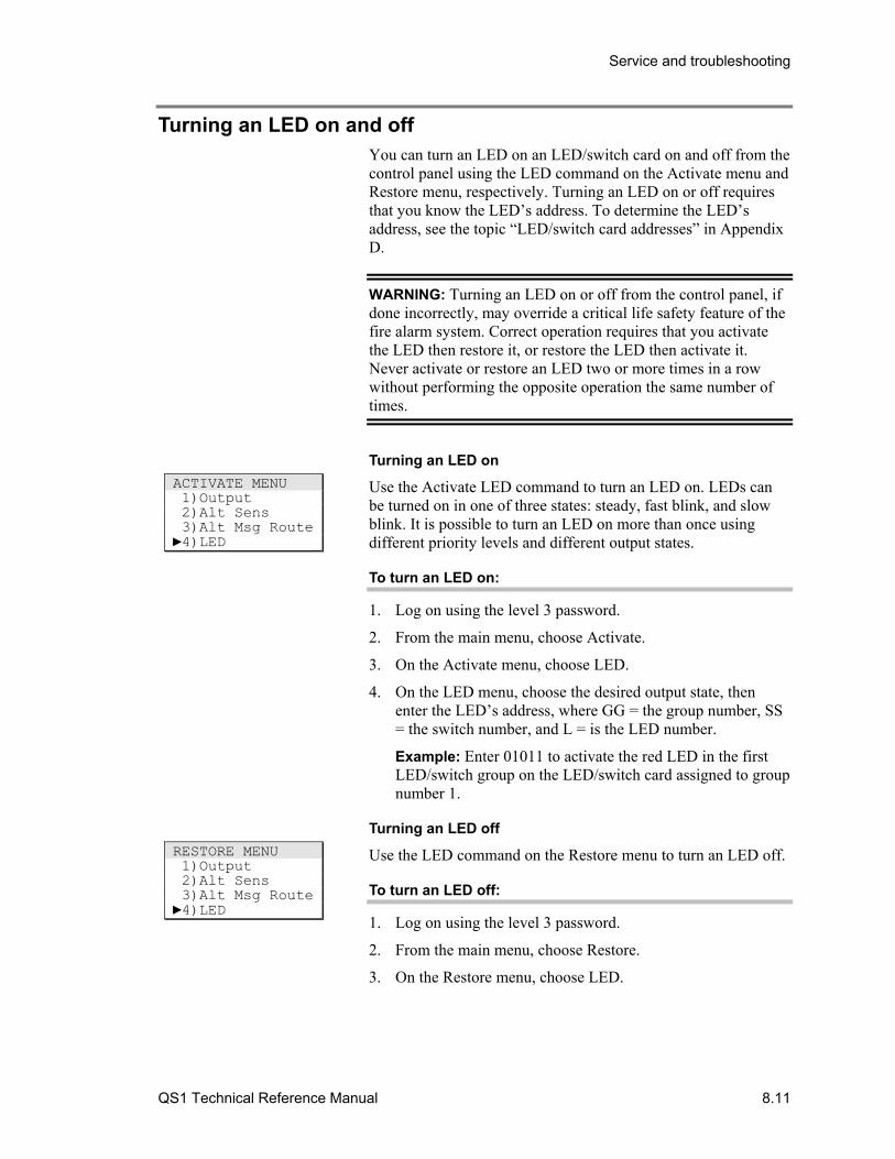
Service and troubleshooting
QS1 Technical Reference Manual 8.11
Turning an LED on and off You can turn an LED on an LED/switch card on and off from the control panel using the LED command on the Activate menu and Restore menu, respectively. Turning an LED on or off requires that you know the LED’s address. To determine the LED’s address, see the topic “LED/switch card addresses” in Appendix D.
WARNING: Turning an LED on or off from the control panel, if done incorrectly, may override a critical life safety feature of the fire alarm system. Correct operation requires that you activate the LED then restore it, or restore the LED then activate it. Never activate or restore an LED two or more times in a row without performing the opposite operation the same number of times.
Turning an LED on
Use the Activate LED command to turn an LED on. LEDs can be turned on in one of three states: steady, fast blink, and slow blink. It is possible to turn an LED on more than once using different priority levels and different output states.
To turn an LED on:
1. Log on using the level 3 password.
2. From the main menu, choose Activate.
3. On the Activate menu, choose LED.
4. On the LED menu, choose the desired output state, then enter the LED’s address, where GG = the group number, SS = the switch number, and L = is the LED number.
Example: Enter 01011 to activate the red LED in the first LED/switch group on the LED/switch card assigned to group number 1.
Turning an LED off
Use the LED command on the Restore menu to turn an LED off.
To turn an LED off:
1. Log on using the level 3 password.
2. From the main menu, choose Restore.
3. On the Restore menu, choose LED.
ACTIVATE MENU 1)Output 2)Alt Sens 3)Alt Msg Route 4)LED
RESTORE MENU 1)Output 2)Alt Sens 3)Alt Msg Route 4)LED

Service and troubleshooting
8.12 QS1 Technical Reference Manual
4. On the LED menu, choose Off, then enter the LED’s address, where GG = the group number, SS = the switch number, and L = is the LED number.
Example: Enter 01011 to restore the red LED in the first LED/switch group on the LED/switch card assigned to group number 1.
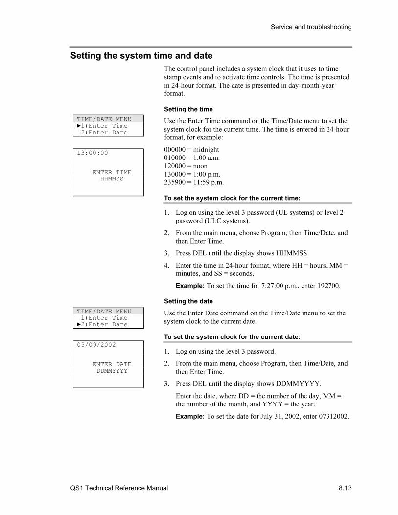
Service and troubleshooting
QS1 Technical Reference Manual 8.13
Setting the system time and date The control panel includes a system clock that it uses to time stamp events and to activate time controls. The time is presented in 24-hour format. The date is presented in day-month-year format.
Setting the time
Use the Enter Time command on the Time/Date menu to set the system clock for the current time. The time is entered in 24-hour format, for example:
000000 = midnight 010000 = 1:00 a.m. 120000 = noon 130000 = 1:00 p.m. 235900 = 11:59 p.m.
To set the system clock for the current time:
1. Log on using the level 3 password (UL systems) or level 2 password (ULC systems).
2. From the main menu, choose Program, then Time/Date, and then Enter Time.
3. Press DEL until the display shows HHMMSS.
4. Enter the time in 24-hour format, where HH = hours, MM = minutes, and SS = seconds.
Example: To set the time for 7:27:00 p.m., enter 192700.
Setting the date
Use the Enter Date command on the Time/Date menu to set the system clock to the current date.
To set the system clock for the current date:
1. Log on using the level 3 password.
2. From the main menu, choose Program, then Time/Date, and then Enter Time.
3. Press DEL until the display shows DDMMYYYY.
Enter the date, where DD = the number of the day, MM = the number of the month, and YYYY = the year.
Example: To set the date for July 31, 2002, enter 07312002.
TIME/DATE MENU 1)Enter Time 2)Enter Date
13:00:00 ENTER TIME HHMMSS
TIME/DATE MENU 1)Enter Time 2)Enter Date
05/09/2002 ENTER DATE DDMMYYYY
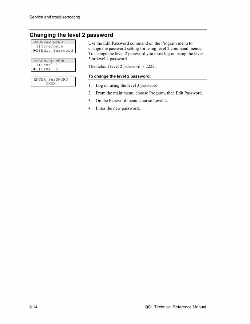
Service and troubleshooting
8.14 QS1 Technical Reference Manual
Changing the level 2 password Use the Edit Password command on the Program menu to change the password setting for using level 2 command menus. To change the level 2 password you must log on using the level 3 or level 4 password.
The default level 2 password is 2222.
To change the level 2 password:
1. Log on using the level 3 password.
2. From the main menu, choose Program, then Edit Password.
3. On the Password menu, choose Level 2.
4. Enter the new password.
PROGRAM MENU 1)Time/Date 2)Edit Password
PASSWORD MENU 1)Level 1 2)Level 2
ENTER PASSWORD XXXX

Service and troubleshooting
QS1 Technical Reference Manual 8.15
Clearing trouble messages Table 8-1 lists the trouble messages that can appear on the CPU/Display Unit and their possible causes. Locate the trouble message in the table then follow the instructions to correct the fault indicated by the message. The trouble messages are listed alphabetically.
Table 8-1: Trouble messages
Message Description
GROUND FAULT: Check System Wiring
There is an earth ground fault in the system. Possible causes for this fault are:
• A computer that is not electrically isolated is connected to the RS-232 port
• A wire shorted to earth ground
Locate the source of the fault by disconnecting the field wires inside the panel one at a time until the fault message clears. Once located, verify the field wiring to clear the short.
TROUBLE Intelligent addressable device trouble. Press Help to identify the specific trouble message.
COMMN FAULT – An intelligent addressable device is not communicating with the panel. Possible causes for this fault are:
• The device is not installed
• The device is installed but is defective
• The loop is wired incorrectly, or the loop wiring is open or shorted
Identify the point that reported the fault by pressing Help. Make corrections as required.
TROUBLE OPEN An open circuit was detected. Possible causes for this fault are:
• Missing or incorrect end of line resistor
• Loose terminal connection or missing device
• Missing or broken wire
Identify the point that reported the fault by pressing Help.
Verify the correct end of line resistor is installed on the last device on the circuit. Verify the field wiring is correct and the connections are secure.
TROUBLE SHRT A short circuit was detected. Possible causes for this fault are:
• A wire-to-wire short
• Wires reversed between two devices
Identify the point that reported the fault by pressing Help. Clear the short.
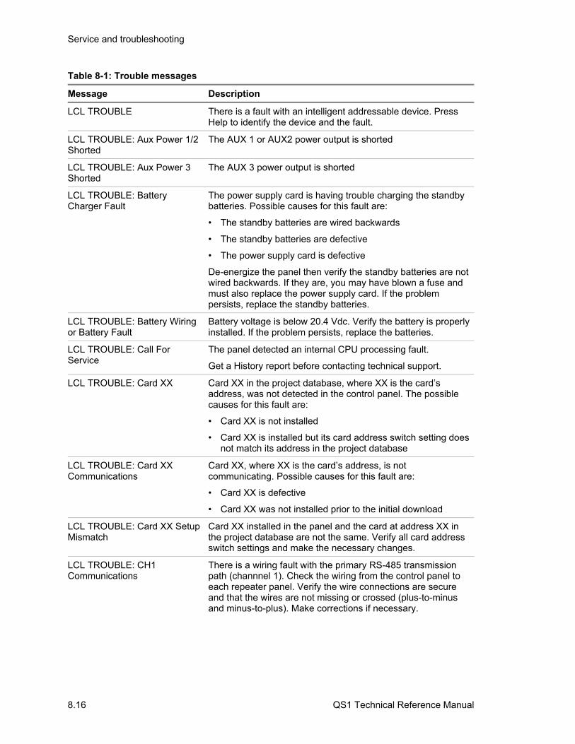
Service and troubleshooting
8.16 QS1 Technical Reference Manual
Table 8-1: Trouble messages
Message Description
LCL TROUBLE There is a fault with an intelligent addressable device. Press Help to identify the device and the fault.
LCL TROUBLE: Aux Power 1/2 Shorted
The AUX 1 or AUX2 power output is shorted
LCL TROUBLE: Aux Power 3 Shorted
The AUX 3 power output is shorted
LCL TROUBLE: Battery Charger Fault
The power supply card is having trouble charging the standby batteries. Possible causes for this fault are:
• The standby batteries are wired backwards
• The standby batteries are defective
• The power supply card is defective
De-energize the panel then verify the standby batteries are not wired backwards. If they are, you may have blown a fuse and must also replace the power supply card. If the problem persists, replace the standby batteries.
LCL TROUBLE: Battery Wiring or Battery Fault
Battery voltage is below 20.4 Vdc. Verify the battery is properly installed. If the problem persists, replace the batteries.
LCL TROUBLE: Call For Service
The panel detected an internal CPU processing fault.
Get a History report before contacting technical support.
LCL TROUBLE: Card XX Card XX in the project database, where XX is the card’s address, was not detected in the control panel. The possible causes for this fault are:
• Card XX is not installed
• Card XX is installed but its card address switch setting does not match its address in the project database
LCL TROUBLE: Card XX Communications
Card XX, where XX is the card’s address, is not communicating. Possible causes for this fault are:
• Card XX is defective
• Card XX was not installed prior to the initial download
LCL TROUBLE: Card XX Setup Mismatch
Card XX installed in the panel and the card at address XX in the project database are not the same. Verify all card address switch settings and make the necessary changes.
LCL TROUBLE: CH1 Communications
There is a wiring fault with the primary RS-485 transmission path (channnel 1). Check the wiring from the control panel to each repeater panel. Verify the wire connections are secure and that the wires are not missing or crossed (plus-to-minus and minus-to-plus). Make corrections if necessary.
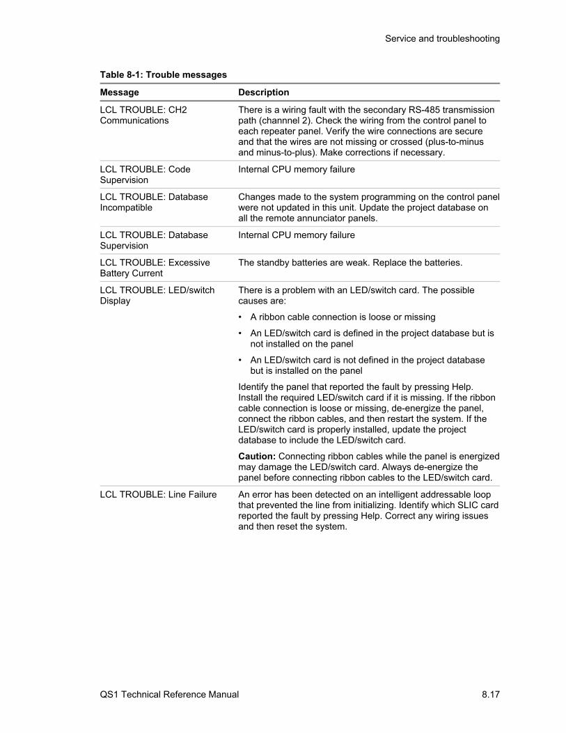
Service and troubleshooting
QS1 Technical Reference Manual 8.17
Table 8-1: Trouble messages
Message Description
LCL TROUBLE: CH2 Communications
There is a wiring fault with the secondary RS-485 transmission path (channnel 2). Check the wiring from the control panel to each repeater panel. Verify the wire connections are secure and that the wires are not missing or crossed (plus-to-minus and minus-to-plus). Make corrections if necessary.
LCL TROUBLE: Code Supervision
Internal CPU memory failure
LCL TROUBLE: Database Incompatible
Changes made to the system programming on the control panel were not updated in this unit. Update the project database on all the remote annunciator panels.
LCL TROUBLE: Database Supervision
Internal CPU memory failure
LCL TROUBLE: Excessive Battery Current
The standby batteries are weak. Replace the batteries.
LCL TROUBLE: LED/switch Display
There is a problem with an LED/switch card. The possible causes are:
• A ribbon cable connection is loose or missing
• An LED/switch card is defined in the project database but is not installed on the panel
• An LED/switch card is not defined in the project database but is installed on the panel
Identify the panel that reported the fault by pressing Help. Install the required LED/switch card if it is missing. If the ribbon cable connection is loose or missing, de-energize the panel, connect the ribbon cables, and then restart the system. If the LED/switch card is properly installed, update the project database to include the LED/switch card.
Caution: Connecting ribbon cables while the panel is energized may damage the LED/switch card. Always de-energize the panel before connecting ribbon cables to the LED/switch card.
LCL TROUBLE: Line Failure An error has been detected on an intelligent addressable loop that prevented the line from initializing. Identify which SLIC card reported the fault by pressing Help. Correct any wiring issues and then reset the system.
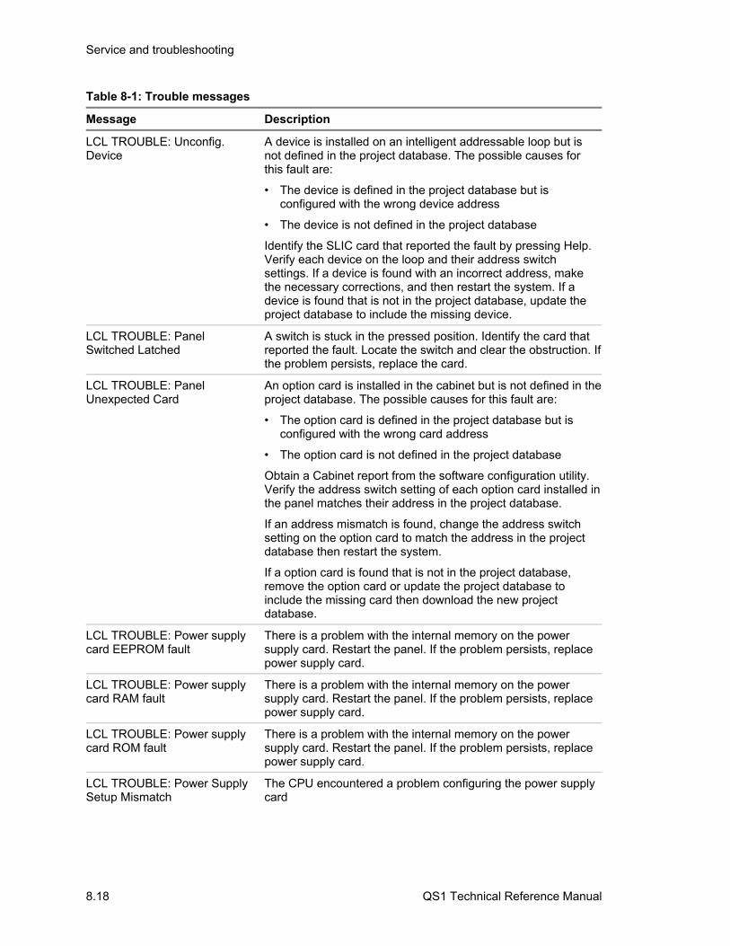
Service and troubleshooting
8.18 QS1 Technical Reference Manual
Table 8-1: Trouble messages
Message Description
LCL TROUBLE: Unconfig. Device
A device is installed on an intelligent addressable loop but is not defined in the project database. The possible causes for this fault are:
• The device is defined in the project database but is configured with the wrong device address
• The device is not defined in the project database
Identify the SLIC card that reported the fault by pressing Help. Verify each device on the loop and their address switch settings. If a device is found with an incorrect address, make the necessary corrections, and then restart the system. If a device is found that is not in the project database, update the project database to include the missing device.
LCL TROUBLE: Panel Switched Latched
A switch is stuck in the pressed position. Identify the card that reported the fault. Locate the switch and clear the obstruction. If the problem persists, replace the card.
LCL TROUBLE: Panel Unexpected Card
An option card is installed in the cabinet but is not defined in the project database. The possible causes for this fault are:
• The option card is defined in the project database but is configured with the wrong card address
• The option card is not defined in the project database
Obtain a Cabinet report from the software configuration utility. Verify the address switch setting of each option card installed in the panel matches their address in the project database.
If an address mismatch is found, change the address switch setting on the option card to match the address in the project database then restart the system.
If a option card is found that is not in the project database, remove the option card or update the project database to include the missing card then download the new project database.
LCL TROUBLE: Power supply card EEPROM fault
There is a problem with the internal memory on the power supply card. Restart the panel. If the problem persists, replace power supply card.
LCL TROUBLE: Power supply card RAM fault
There is a problem with the internal memory on the power supply card. Restart the panel. If the problem persists, replace power supply card.
LCL TROUBLE: Power supply card ROM fault
There is a problem with the internal memory on the power supply card. Restart the panel. If the problem persists, replace power supply card.
LCL TROUBLE: Power Supply Setup Mismatch
The CPU encountered a problem configuring the power supply card
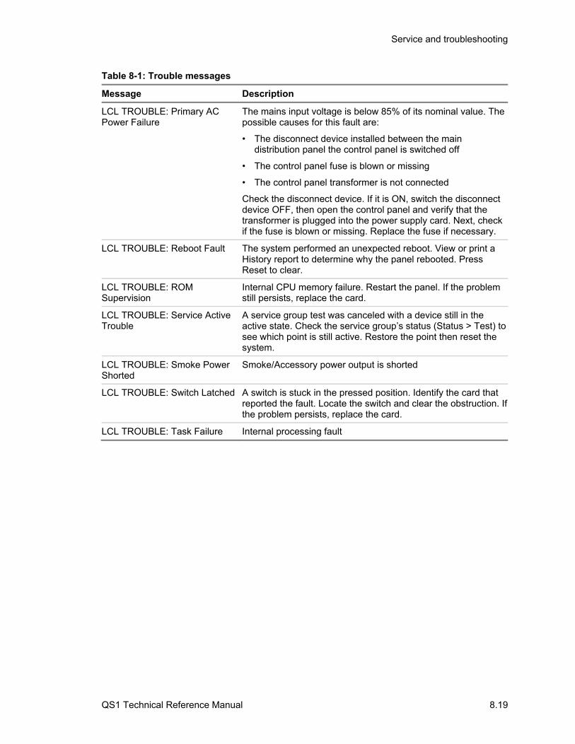
Service and troubleshooting
QS1 Technical Reference Manual 8.19
Table 8-1: Trouble messages
Message Description
LCL TROUBLE: Primary AC Power Failure
The mains input voltage is below 85% of its nominal value. The possible causes for this fault are:
• The disconnect device installed between the main distribution panel the control panel is switched off
• The control panel fuse is blown or missing
• The control panel transformer is not connected
Check the disconnect device. If it is ON, switch the disconnect device OFF, then open the control panel and verify that the transformer is plugged into the power supply card. Next, check if the fuse is blown or missing. Replace the fuse if necessary.
LCL TROUBLE: Reboot Fault The system performed an unexpected reboot. View or print a History report to determine why the panel rebooted. Press Reset to clear.
LCL TROUBLE: ROM Supervision
Internal CPU memory failure. Restart the panel. If the problem still persists, replace the card.
LCL TROUBLE: Service Active Trouble
A service group test was canceled with a device still in the active state. Check the service group’s status (Status > Test) to see which point is still active. Restore the point then reset the system.
LCL TROUBLE: Smoke Power Shorted
Smoke/Accessory power output is shorted
LCL TROUBLE: Switch Latched A switch is stuck in the pressed position. Identify the card that reported the fault. Locate the switch and clear the obstruction. If the problem persists, replace the card.
LCL TROUBLE: Task Failure Internal processing fault
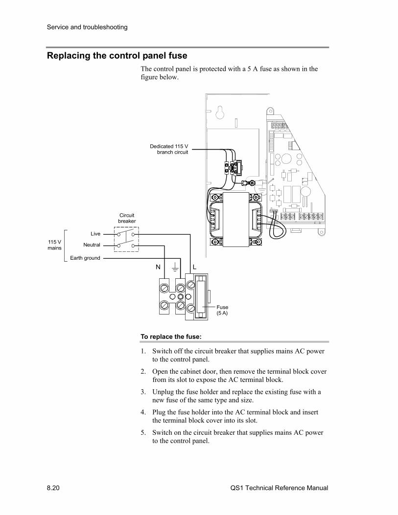
Service and troubleshooting
8.20 QS1 Technical Reference Manual
Replacing the control panel fuse The control panel is protected with a 5 A fuse as shown in the figure below.
Dedicated 115 Vbranch circuit
Neutral
Live
Earth ground
115 Vmains
Fuse(5 A)
LN
Circuitbreaker
To replace the fuse:
1. Switch off the circuit breaker that supplies mains AC power to the control panel.
2. Open the cabinet door, then remove the terminal block cover from its slot to expose the AC terminal block.
3. Unplug the fuse holder and replace the existing fuse with a new fuse of the same type and size.
4. Plug the fuse holder into the AC terminal block and insert the terminal block cover into its slot.
5. Switch on the circuit breaker that supplies mains AC power to the control panel.
Service and troubleshooting
QS1 Technical Reference Manual 8.21
Using HyperTerminal HyperTerminal is a useful tool for gathering information from the control panel through an RS-232 port connection in order to troubleshoot system faults. The information gathered can be saved as a plain text file (TXT extension) and submitted electronically to technical support for evaluation.
HyperTerminal comes with your Windows operating system as an installable option. HyperTerminal, if installed, is typically found on the Accessories menu (Start > Programs > Accessories > Hyperterminal).
Note: HyperTerminal Professional Edition is available free of charge for personal use. You can download HyperTerminal Professional Edition from the Internet at http://www.hilgraeve.com.
Setting up a HyperTerminal connection
Before you can gather information from the control panel you must set up a HyperTerminal connection.
To set up a HyperTerminal connection:
1. Start HyperTerminal.
2. In the Connection Description dialog box, type a name for the connection in the Name box then click OK.
3. In the Connect To dialog box, select the COM port you are using to connect your laptop computer to the control panel then click OK.
4. In the COM port’s Properties dialog box, set the port settings as described below then click OK.
Bits per second: 9600 Data bits: 8 Parity: None Stop bits: 1 Flow control: None
5. On the File menu, click Save to save your connection settings.
Capturing a report
The history report and the revisions report provide useful information for troubleshooting system faults. You should always have this information available before calling technical support.

Service and troubleshooting
8.22 QS1 Technical Reference Manual
To capture a report:
1. On the Transfer menu, click Capture Text.
2. In the File box in the Capture Text dialog box, type a name for the captured text file. Example: history report. The TXT file extension is added automatically.
If you want to save the file to somewhere other than the default location, click the Browse button, navigate to the desired location, then name the file.
3. Click Start.
4. From the Control/Display Unit, log on using the level 3 password.
5. From the main menu, choose Reports, then choose the report you want captured.
6. On the Print Output menu, choose Printer to send the report to HyperTerminal.
7. Wait until the report transfer is complete.
8. On the Transfer menu, click Capture Text, and then Stop.
QS1 Technical Reference Manual A.1
Appendix A System calculations
Summary
This appendix provides worksheets for sizing standby batteries, and for calculating the maximum wire lengths for notification appliance circuits and intelligent addressable loops.
Content
Notification appliance circuit calculations • A.2 Introduction • A.2 What you’ll need • A.2 Worksheet method • A.4 Equation method • A.5
Intelligent addressable loop maximum wire length • A.8 Battery calculations • A.14

System calculations
A.2 QS1 Technical Reference Manual
Notification appliance circuit calculations
Introduction
This topic shows you how to determine the maximum cable length of an NAC circuit for a given number of appliances.
Two methods are presented: worksheet and equation. The worksheet method is simpler, but your installation must meet the criteria listed on the worksheet. If your installation does not meet these criteria, you need to use the equation method.
The methods given here determine cable lengths that work under all operating conditions. The calculations ensure that the required operating voltage and current will be supplied to all notification appliances. To do this, we assume these two worst-case conditions:
• The voltage at the NAC terminals is the minimum provided by the power supply
• The notification appliances are clustered at the end of the NAC cable
Other, more detailed methods that distribute the appliance load along the NAC cable may indicate that longer cable runs are possible.
What you’ll need
Appliance and cable values
Whether you use the worksheet method or the equation method, you’ll need to know:
• The minimum operating voltage required for the appliances
• The maximum operating current drawn by each appliance
• The resistance per unit length of the wire used (Ω/ft)
This information can be found on the appliance installation sheets, and on the cable specification sheet.
Power supply values
For either method, you’ll need some fixed or calculated operating values for your specific power supply. The fixed values are:
• Maximum voltage = 25.1 V • Rated voltage = 20.4 V • Load factor = 0.0 V/A • Power type = FWR

System calculations
QS1 Technical Reference Manual A.3
The maximum voltage is the highest voltage measured at the NAC terminals. This value is not used in the calculations, but is given so you can ensure appliance compatibility.
The rated voltage is the theoretical operating minimum for the power supply, and is calculated as 85% of 24 volts.
The load factor is a measure of how the power supply voltage reacts when a load is applied. The load factor measures the voltage drop per ampere of current drawn by the load.
The power type reflects the type of power supplied to the NAC terminals at minimum voltage. The current draw of notification appliances can vary substantially with the type of power supplied: full-wave rectified (Vfwr) or direct current (Vdc). It is important to know the power type at minimum terminal voltage.
You’ll need to calculate the following values relating to your power supply and to the NAC circuit current. These are:
• Minimum voltage • Voltage drop
The minimum voltage is the lowest voltage measured at the NAC terminals when the power supply is under the maximum load for that circuit (i.e. for the appliances that constitute the NAC.)
The voltage drop is the difference between the minimum voltage and 16 V. This value is for use with the worksheet only.
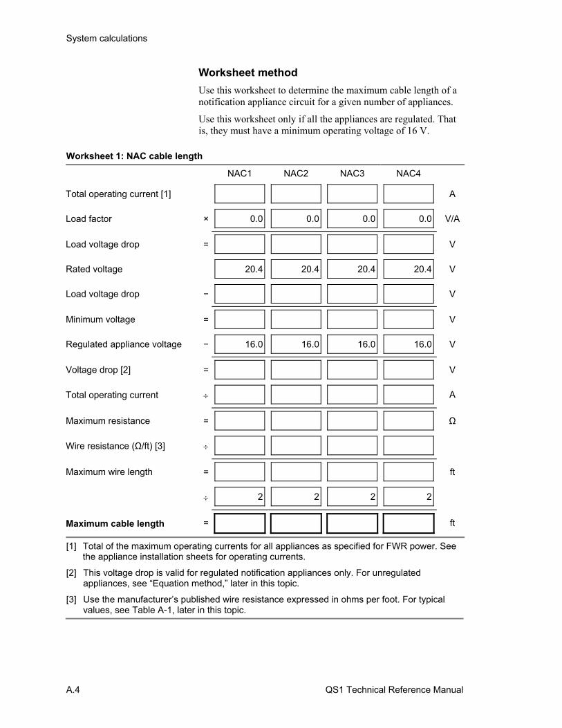
System calculations
A.4 QS1 Technical Reference Manual
Worksheet method
Use this worksheet to determine the maximum cable length of a notification appliance circuit for a given number of appliances.
Use this worksheet only if all the appliances are regulated. That is, they must have a minimum operating voltage of 16 V.
Worksheet 1: NAC cable length
NAC1 NAC2 NAC3 NAC4
Total operating current [1] A
Load factor × 0.0 0.0 0.0 0.0 V/A
Load voltage drop = V
Rated voltage 20.4 20.4 20.4 20.4 V
Load voltage drop − V
Minimum voltage = V
Regulated appliance voltage − 16.0 16.0 16.0 16.0 V
Voltage drop [2] = V
Total operating current A
Maximum resistance = Ω
Wire resistance (Ω/ft) [3]
Maximum wire length = ft
2 2 2 2
Maximum cable length = ft
[1] Total of the maximum operating currents for all appliances as specified for FWR power. See the appliance installation sheets for operating currents.
[2] This voltage drop is valid for regulated notification appliances only. For unregulated appliances, see “Equation method,” later in this topic.
[3] Use the manufacturer’s published wire resistance expressed in ohms per foot. For typical values, see Table A-1, later in this topic.
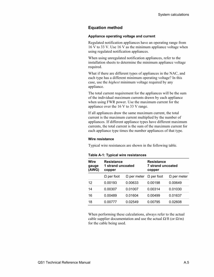
System calculations
QS1 Technical Reference Manual A.5
Equation method
Appliance operating voltage and current
Regulated notification appliances have an operating range from 16 V to 33 V. Use 16 V as the minimum appliance voltage when using regulated notification appliances.
When using unregulated notification appliances, refer to the installation sheets to determine the minimum appliance voltage required.
What if there are different types of appliances in the NAC, and each type has a different minimum operating voltage? In this case, use the highest minimum voltage required by any appliance.
The total current requirement for the appliances will be the sum of the individual maximum currents drawn by each appliance when using FWR power. Use the maximum current for the appliance over the 16 V to 33 V range.
If all appliances draw the same maximum current, the total current is the maximum current multiplied by the number of appliances. If different appliance types have different maximum currents, the total current is the sum of the maximum current for each appliance type times the number appliances of that type.
Wire resistance
Typical wire resistances are shown in the following table. Table A-1: Typical wire resistances
Wire gauge (AWG)
Resistance 1 strand uncoated copper
Resistance 7 strand uncoated copper
Ω per foot Ω per meter Ω per foot Ω per meter
12 0.00193 0.00633 0.00198 0.00649
14 0.00307 0.01007 0.00314 0.01030
16 0.00489 0.01604 0.00499 0.01637
18 0.00777 0.02549 0.00795 0.02608
When performing these calculations, always refer to the actual cable supplier documentation and use the actual Ω/ft (or Ω/m) for the cable being used.

System calculations
A.6 QS1 Technical Reference Manual
Calculating cable length
To calculate the maximum NAC cable length:
1. Calculate the total current (Itot) as the sum of the maximum operating currents for all the appliances.
Itot = ΣIa
Where: Ia = appliance maximum current
See the appliance installation sheets for Ia. Remember to use the maximum operating current specified for FWR power.
2. Calculate the minimum voltage (Vm).
Vm = Vr − (Itot × K)
Where: Vr = rated voltage Itot = total current (from above) K = load factor
For the power supply, Vr is 20.4 V and K is 0.0 V/A.
3. Calculate the allowable voltage drop (Vd) between the power supply and the appliances.
Vd = Vm − Va
Where: Vm = minimum voltage (from above) Va = appliance minimum voltage
For regulated notification appliances, Va is 16 V. For unregulated notification appliances, Va is the lowest operating voltage specified on the appliance installation sheet.
4. Calculate the maximum resistance (Rmax) the wire can have.
Rmax = Vd / Itot
Where: Vd = voltage drop Itot = total current
5. Calculate the maximum length of the cable (Lc), based on the maximum resistance allowed, the resistance of the wire, and the number of wires in the cable (two).
Lc = (Rmax / Rw) / 2
Where: Rmax = maximum resistance Rw = wire resistance factor

System calculations
QS1 Technical Reference Manual A.7
Example: You’re using regulated notification appliances. Assume that the maximum operating current for each appliance is 100 mA for FWR power, and that 20 appliances will be placed on the NAC. The cable is 12 AWG wire, and the manufacturer specifies a wire resistance factor of 0.002 Ω/ft.
Itot = Ia = 20 × 0.1 A = 2 A
Vm = Vr − (Itot × K) = 20.4 V − (2 A × 0.0 V/A) = 20.4 V − 0.0 V = 20.4 V
Vd = Vm − Va = 20.4 V − 16.0 V = 4.4 V
Rmax = Vd / Itot = 4.4 V / 2.0 A = 2.2 Ω
Lc = (Rmax / Rw) / 2 = (2.2 Ω / 0.002 Ω/ft) / 2 = 1100 ft / 2 = 550 ft
So the maximum wire run for this NAC would be 550 ft (rounding down for safety).
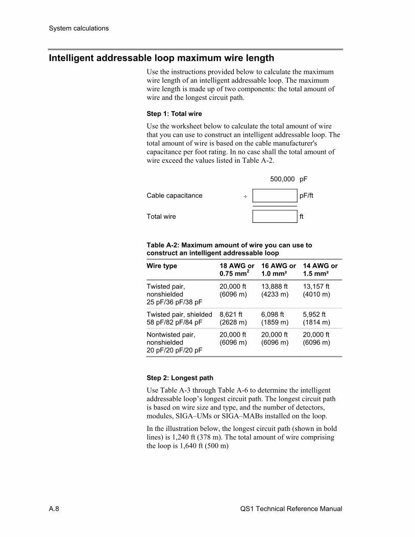
System calculations
A.8 QS1 Technical Reference Manual
Intelligent addressable loop maximum wire length Use the instructions provided below to calculate the maximum wire length of an intelligent addressable loop. The maximum wire length is made up of two components: the total amount of wire and the longest circuit path.
Step 1: Total wire
Use the worksheet below to calculate the total amount of wire that you can use to construct an intelligent addressable loop. The total amount of wire is based on the cable manufacturer's capacitance per foot rating. In no case shall the total amount of wire exceed the values listed in Table A-2. 500,000 pF
Cable capacitance pF/ft
Total wire ft
Table A-2: Maximum amount of wire you can use to construct an intelligent addressable loop
Wire type 18 AWG or0.75 mm2
16 AWG or 1.0 mm²
14 AWG or1.5 mm²
Twisted pair, nonshielded 25 pF/36 pF/38 pF
20,000 ft (6096 m)
13,888 ft (4233 m)
13,157 ft (4010 m)
Twisted pair, shielded58 pF/82 pF/84 pF
8,621 ft (2628 m)
6,098 ft (1859 m)
5,952 ft (1814 m)
Nontwisted pair, nonshielded 20 pF/20 pF/20 pF
20,000 ft (6096 m)
20,000 ft (6096 m)
20,000 ft (6096 m)
Step 2: Longest path
Use Table A-3 through Table A-6 to determine the intelligent addressable loop’s longest circuit path. The longest circuit path is based on wire size and type, and the number of detectors, modules, SIGA–UMs or SIGA–MABs installed on the loop.
In the illustration below, the longest circuit path (shown in bold lines) is 1,240 ft (378 m). The total amount of wire comprising the loop is 1,640 ft (500 m)

System calculations
QS1 Technical Reference Manual A.9
FACP J
J
10 ft(3 m) 200 ft
(61 m)
30 ft(9 m)
J
100 ft(30 m)
1000 ft(305 m)
200 ft(61 m)
100 ft(30 m)

System calculations
A.10 QS1 Technical Reference Manual
Table A-3: Longest allowable circuit path with 0 SIGA-UMs or SIGA-MABs configured for 2-wire smoke detectors
Detector addresses
Module addresses
Maximum allowable wire distance using nontwisted, nonshielded wire pairs
18 AWG 16 AWG 14 AWG
ft m ft m ft m
1 to 25 0 7437 2267 11815 3601 18792 5728
26 to 50 0 7038 2145 11180 3408 17782 5420
51 to 75 0 6638 2023 10545 3214 16772 5112
76 to 100 0 6238 1901 9910 3021 15762 4804
101 to 125 0 5839 1780 9275 2827 14752 4497
0 1 to 25 7267 2215 11544 3519 18361 5597
1 to 25 1 to 25 6867 2093 10909 3325 17351 5289
26 to 50 1 to 25 6467 1971 10275 3132 16342 4981
51 to 75 1 to 25 6068 1849 9640 2938 15332 4673
76 to 100 1 to 25 5668 1728 9005 2745 14322 4365
101 to 125 1 to 25 5268 1606 8370 2551 13312 4057
0 26 to 50 6697 2041 10639 3243 16921 5157
1 to 25 26 to 50 6297 1919 10004 3049 15911 4850
26 to 50 26 to 50 5897 1798 9369 2856 14901 4542
51 to 75 26 to 50 5498 1676 8734 2662 13891 4234
76 to 100 26 to 50 5098 1554 8099 2469 12881 3926
101 to 125 26 to 50 4698 1432 7464 2275 11871 3618
0 51 to 75 5906 1800 9383 2860 14923 4549
1 to 25 51 to 75 5250 1600 8340 2542 13265 4043
26 to 50 51 to 75 4633 1412 7360 2243 11707 3568
51 to 75 51 to 75 4051 1235 6435 1961 10235 3120
76 to 100 51 to 75 3498 1066 5558 1694 8839 2694
101 to 125 51 to 75 2973 906 4723 1440 7512 2290
0 76 to 100 3931 1198 6245 1903 9932 3027
1 to 25 76 to 100 3404 1037 5407 1648 8601 2621
26 to 50 76 to 100 2899 883 4605 1404 7324 2232
51 to 75 76 to 100 2413 735 3833 1168 6096 1858
76 to 100 76 to 100 1945 593 3089 942 4913 1498
101 to 125 76 to 100 1493 455 2371 723 3771 1149
0 101 to 125 2631 802 4180 1274 6649 2027
1 to 25 101 to 125 2165 660 3439 1048 5470 1667
26 to 50 101 to 125 1713 522 2721 829 4328 1319
51 to 75 101 to 125 1274 388 2023 617 3218 981
76 to 100 101 to 125 847 258 1345 410 2140 652
101 to 125 101 to 125 431 131 685 209 1089 332
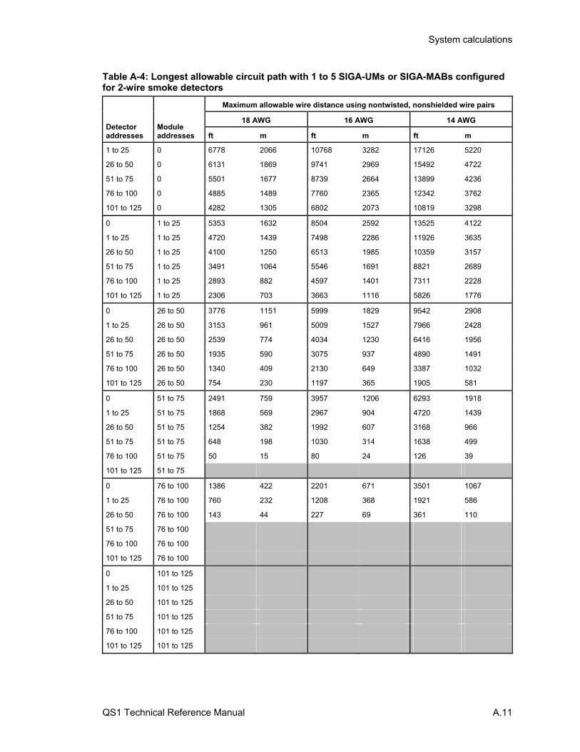
System calculations
QS1 Technical Reference Manual A.11
Table A-4: Longest allowable circuit path with 1 to 5 SIGA-UMs or SIGA-MABs configured for 2-wire smoke detectors
Detector addresses
Module addresses
Maximum allowable wire distance using nontwisted, nonshielded wire pairs
18 AWG 16 AWG 14 AWG
ft m ft m ft m
1 to 25 0 6778 2066 10768 3282 17126 5220
26 to 50 0 6131 1869 9741 2969 15492 4722
51 to 75 0 5501 1677 8739 2664 13899 4236
76 to 100 0 4885 1489 7760 2365 12342 3762
101 to 125 0 4282 1305 6802 2073 10819 3298
0 1 to 25 5353 1632 8504 2592 13525 4122
1 to 25 1 to 25 4720 1439 7498 2286 11926 3635
26 to 50 1 to 25 4100 1250 6513 1985 10359 3157
51 to 75 1 to 25 3491 1064 5546 1691 8821 2689
76 to 100 1 to 25 2893 882 4597 1401 7311 2228
101 to 125 1 to 25 2306 703 3663 1116 5826 1776
0 26 to 50 3776 1151 5999 1829 9542 2908
1 to 25 26 to 50 3153 961 5009 1527 7966 2428
26 to 50 26 to 50 2539 774 4034 1230 6416 1956
51 to 75 26 to 50 1935 590 3075 937 4890 1491
76 to 100 26 to 50 1340 409 2130 649 3387 1032
101 to 125 26 to 50 754 230 1197 365 1905 581
0 51 to 75 2491 759 3957 1206 6293 1918
1 to 25 51 to 75 1868 569 2967 904 4720 1439
26 to 50 51 to 75 1254 382 1992 607 3168 966
51 to 75 51 to 75 648 198 1030 314 1638 499
76 to 100 51 to 75 50 15 80 24 126 39
101 to 125 51 to 75
0 76 to 100 1386 422 2201 671 3501 1067
1 to 25 76 to 100 760 232 1208 368 1921 586
26 to 50 76 to 100 143 44 227 69 361 110
51 to 75 76 to 100
76 to 100 76 to 100
101 to 125 76 to 100
0 101 to 125
1 to 25 101 to 125
26 to 50 101 to 125
51 to 75 101 to 125
76 to 100 101 to 125
101 to 125 101 to 125
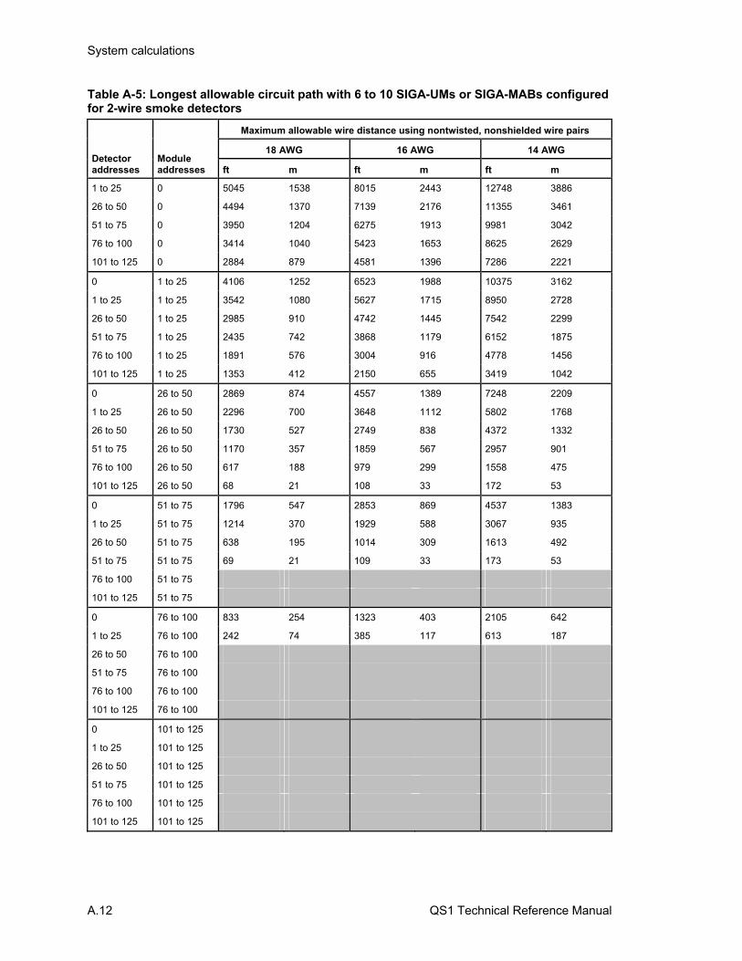
System calculations
A.12 QS1 Technical Reference Manual
Table A-5: Longest allowable circuit path with 6 to 10 SIGA-UMs or SIGA-MABs configured for 2-wire smoke detectors
Detector addresses
Module addresses
Maximum allowable wire distance using nontwisted, nonshielded wire pairs
18 AWG 16 AWG 14 AWG
ft m ft m ft m
1 to 25 0 5045 1538 8015 2443 12748 3886
26 to 50 0 4494 1370 7139 2176 11355 3461
51 to 75 0 3950 1204 6275 1913 9981 3042
76 to 100 0 3414 1040 5423 1653 8625 2629
101 to 125 0 2884 879 4581 1396 7286 2221
0 1 to 25 4106 1252 6523 1988 10375 3162
1 to 25 1 to 25 3542 1080 5627 1715 8950 2728
26 to 50 1 to 25 2985 910 4742 1445 7542 2299
51 to 75 1 to 25 2435 742 3868 1179 6152 1875
76 to 100 1 to 25 1891 576 3004 916 4778 1456
101 to 125 1 to 25 1353 412 2150 655 3419 1042
0 26 to 50 2869 874 4557 1389 7248 2209
1 to 25 26 to 50 2296 700 3648 1112 5802 1768
26 to 50 26 to 50 1730 527 2749 838 4372 1332
51 to 75 26 to 50 1170 357 1859 567 2957 901
76 to 100 26 to 50 617 188 979 299 1558 475
101 to 125 26 to 50 68 21 108 33 172 53
0 51 to 75 1796 547 2853 869 4537 1383
1 to 25 51 to 75 1214 370 1929 588 3067 935
26 to 50 51 to 75 638 195 1014 309 1613 492
51 to 75 51 to 75 69 21 109 33 173 53
76 to 100 51 to 75
101 to 125 51 to 75
0 76 to 100 833 254 1323 403 2105 642
1 to 25 76 to 100 242 74 385 117 613 187
26 to 50 76 to 100
51 to 75 76 to 100
76 to 100 76 to 100
101 to 125 76 to 100
0 101 to 125
1 to 25 101 to 125
26 to 50 101 to 125
51 to 75 101 to 125
76 to 100 101 to 125
101 to 125 101 to 125
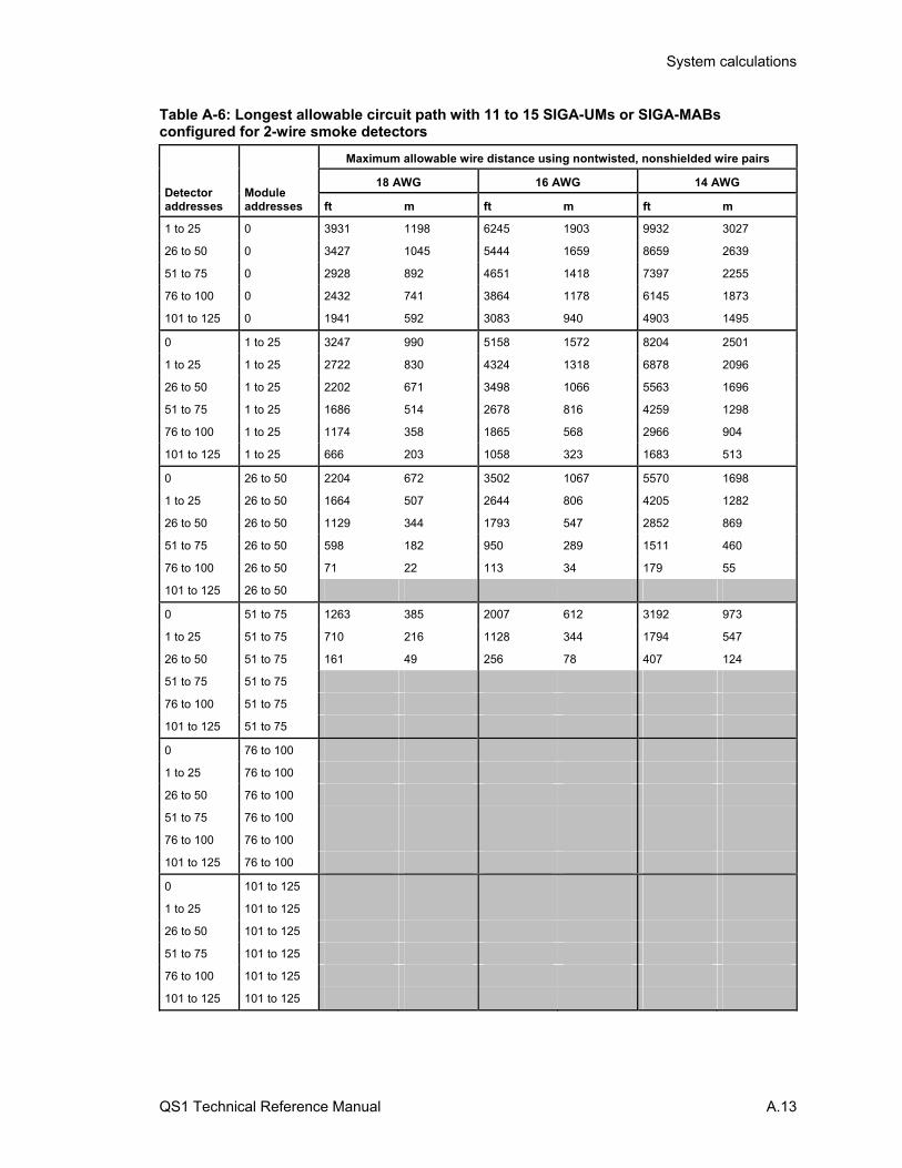
System calculations
QS1 Technical Reference Manual A.13
Table A-6: Longest allowable circuit path with 11 to 15 SIGA-UMs or SIGA-MABs configured for 2-wire smoke detectors
Detector addresses
Module addresses
Maximum allowable wire distance using nontwisted, nonshielded wire pairs
18 AWG 16 AWG 14 AWG
ft m ft m ft m
1 to 25 0 3931 1198 6245 1903 9932 3027
26 to 50 0 3427 1045 5444 1659 8659 2639
51 to 75 0 2928 892 4651 1418 7397 2255
76 to 100 0 2432 741 3864 1178 6145 1873
101 to 125 0 1941 592 3083 940 4903 1495
0 1 to 25 3247 990 5158 1572 8204 2501
1 to 25 1 to 25 2722 830 4324 1318 6878 2096
26 to 50 1 to 25 2202 671 3498 1066 5563 1696
51 to 75 1 to 25 1686 514 2678 816 4259 1298
76 to 100 1 to 25 1174 358 1865 568 2966 904
101 to 125 1 to 25 666 203 1058 323 1683 513
0 26 to 50 2204 672 3502 1067 5570 1698
1 to 25 26 to 50 1664 507 2644 806 4205 1282
26 to 50 26 to 50 1129 344 1793 547 2852 869
51 to 75 26 to 50 598 182 950 289 1511 460
76 to 100 26 to 50 71 22 113 34 179 55
101 to 125 26 to 50
0 51 to 75 1263 385 2007 612 3192 973
1 to 25 51 to 75 710 216 1128 344 1794 547
26 to 50 51 to 75 161 49 256 78 407 124
51 to 75 51 to 75
76 to 100 51 to 75
101 to 125 51 to 75
0 76 to 100
1 to 25 76 to 100
26 to 50 76 to 100
51 to 75 76 to 100
76 to 100 76 to 100
101 to 125 76 to 100
0 101 to 125
1 to 25 101 to 125
26 to 50 101 to 125
51 to 75 101 to 125
76 to 100 101 to 125
101 to 125 101 to 125
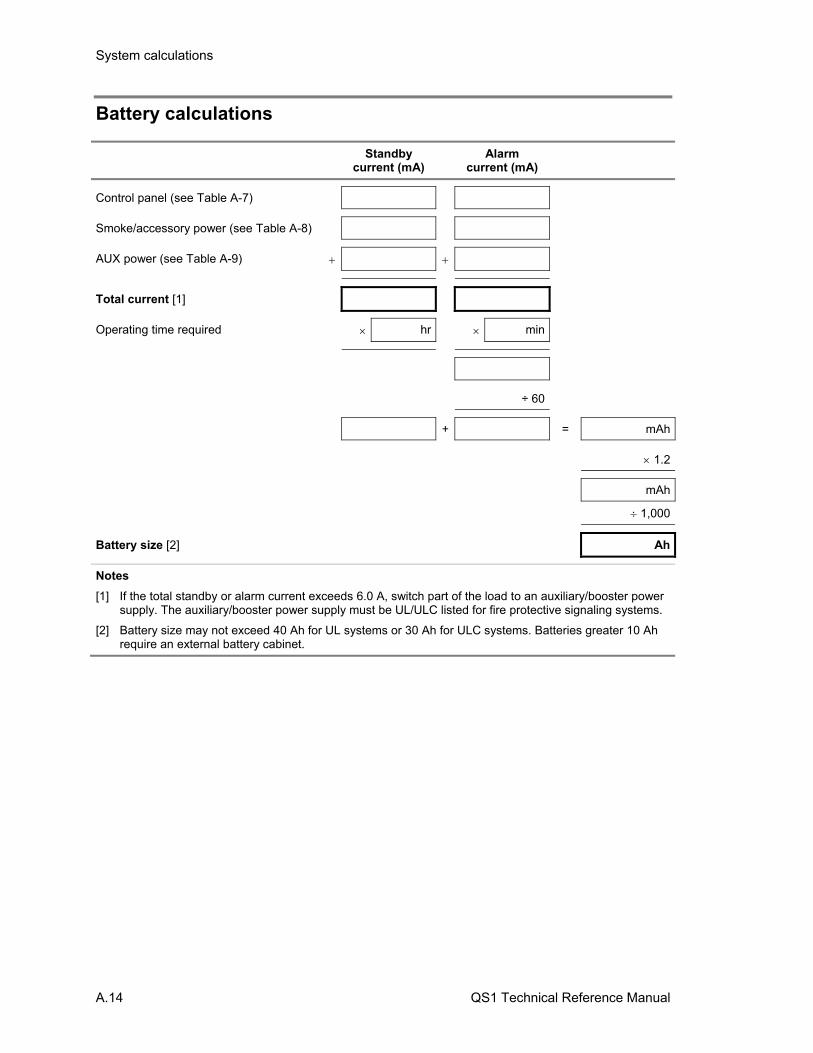
System calculations
A.14 QS1 Technical Reference Manual
Battery calculations
Standby current (mA)
Alarm current (mA)
Control panel (see Table A-7)
Smoke/accessory power (see Table A-8)
AUX power (see Table A-9)
Total current [1]
Operating time required hr min
÷ 60
+ = mAh
1.2
mAh
1,000
Battery size [2] Ah
Notes
[1] If the total standby or alarm current exceeds 6.0 A, switch part of the load to an auxiliary/booster power supply. The auxiliary/booster power supply must be UL/ULC listed for fire protective signaling systems.
[2] Battery size may not exceed 40 Ah for UL systems or 30 Ah for ULC systems. Batteries greater 10 Ah require an external battery cabinet.
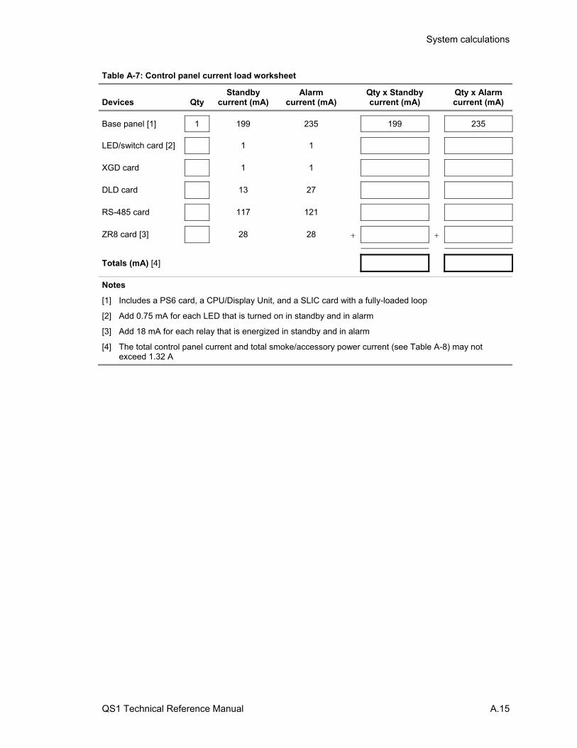
System calculations
QS1 Technical Reference Manual A.15
Table A-7: Control panel current load worksheet
Devices
Qty
Standby current (mA)
Alarm current (mA)
Qty x Standby current (mA)
Qty x Alarm current (mA)
Base panel [1] 1 199 235 199 235
LED/switch card [2] 1 1
XGD card 1 1
DLD card 13 27
RS-485 card 117 121
ZR8 card [3] 28 28
Totals (mA) [4]
Notes
[1] Includes a PS6 card, a CPU/Display Unit, and a SLIC card with a fully-loaded loop
[2] Add 0.75 mA for each LED that is turned on in standby and in alarm
[3] Add 18 mA for each relay that is energized in standby and in alarm
[4] The total control panel current and total smoke/accessory power current (see Table A-8) may not exceed 1.32 A
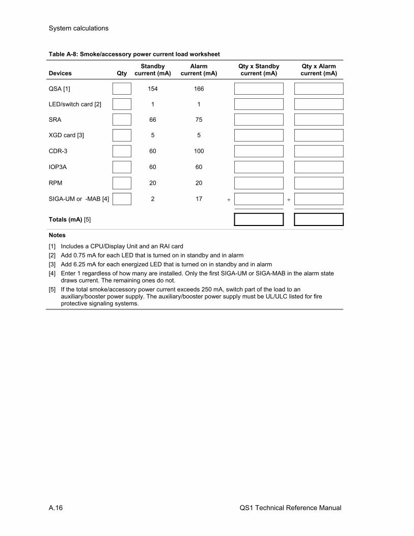
System calculations
A.16 QS1 Technical Reference Manual
Table A-8: Smoke/accessory power current load worksheet
Devices
Qty
Standby current (mA)
Alarm current (mA)
Qty x Standby current (mA)
Qty x Alarm current (mA)
QSA [1] 154 166
LED/switch card [2] 1 1
SRA 66 75
XGD card [3] 5 5
CDR-3 60 100
IOP3A 60 60
RPM 20 20
SIGA-UM or -MAB [4] 2 17
Totals (mA) [5]
Notes
[1] Includes a CPU/Display Unit and an RAI card
[2] Add 0.75 mA for each LED that is turned on in standby and in alarm
[3] Add 6.25 mA for each energized LED that is turned on in standby and in alarm
[4] Enter 1 regardless of how many are installed. Only the first SIGA-UM or SIGA-MAB in the alarm state draws current. The remaining ones do not.
[5] If the total smoke/accessory power current exceeds 250 mA, switch part of the load to an auxiliary/booster power supply. The auxiliary/booster power supply must be UL/ULC listed for fire protective signaling systems.
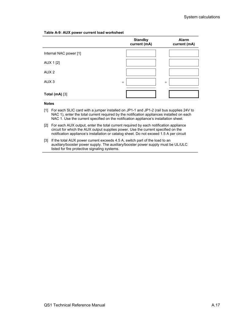
System calculations
QS1 Technical Reference Manual A.17
Table A-9: AUX power current load worksheet
Standby current (mA)
Alarm current (mA)
Internal NAC power [1]
AUX 1 [2]
AUX 2
AUX 3
Total (mA) [3]
Notes
[1] For each SLIC card with a jumper installed on JP1-1 and JP1-2 (rail bus supplies 24V to NAC 1), enter the total current required by the notification appliances installed on each NAC 1. Use the current specified on the notification appliance’s installation sheet.
[2] For each AUX output, enter the total current required by each notification appliance circuit for which the AUX output supplies power. Use the current specified on the notification appliance’s installation or catalog sheet. Do not exceed 1.5 A per circuit
[3] If the total AUX power current exceeds 4.5 A, switch part of the load to an auxiliary/booster power supply. The auxiliary/booster power supply must be UL/ULC listed for fire protective signaling systems.

System calculations
A.18 QS1 Technical Reference Manual
QS1 Technical Reference Manual B.1
Appendix B Barcode library
Summary
This appendix provides a set of barcodes that you can use to add location descriptions to event messages from the control panel CPU/Display Unit.
Content
Uppercase letters • B.2 Numbers and ordinals • B.2 Common words • B.3
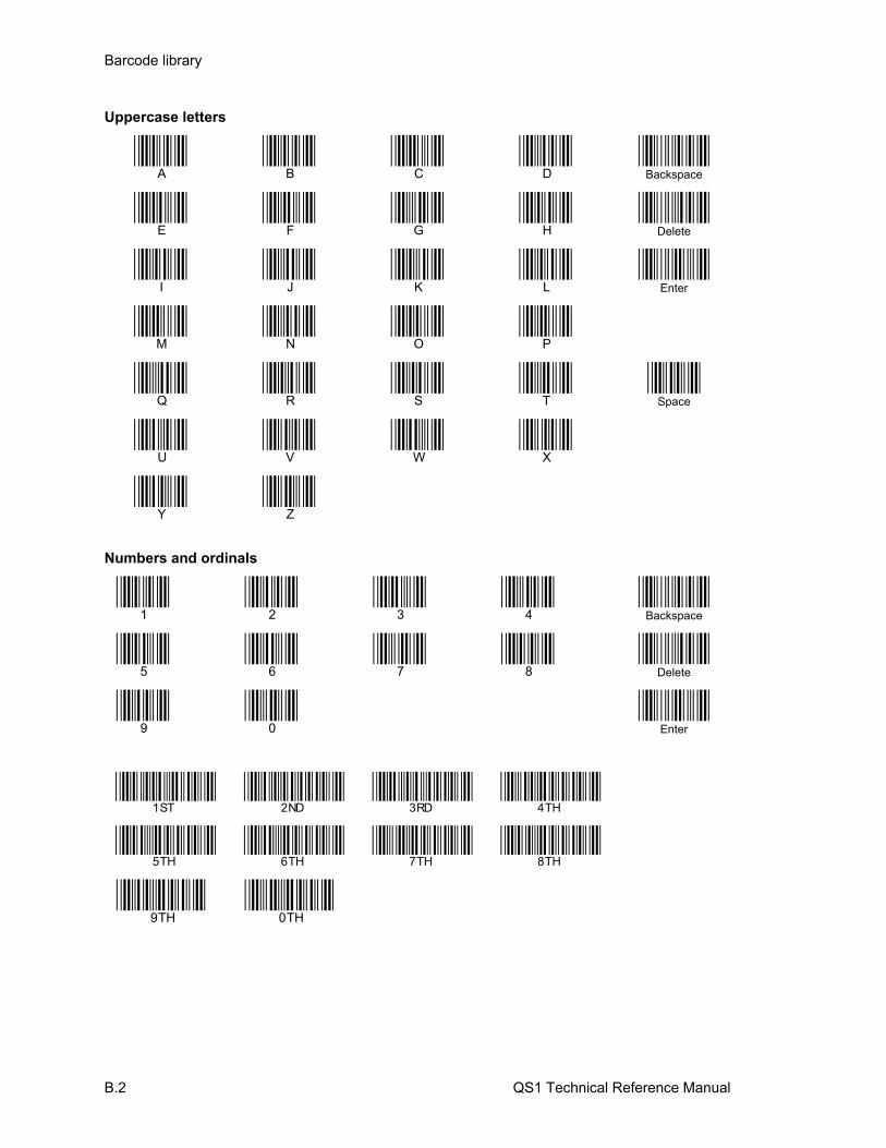
Barcode library
B.2 QS1 Technical Reference Manual
Uppercase letters
A B C D
Backspace
E F G H
Delete
I J K L
Enter
M N O P
Q R S T
Space
U V W X
Y Z
Numbers and ordinals
1 2 3 4
Backspace
5 6 7 8
Delete
9 0
Enter
1ST 2ND 3RD 4TH
5TH 6TH 7TH 8TH
9TH 0TH

Barcode library
QS1 Technical Reference Manual B.3
Common words
ABORT
ABOVE
ALARM
APARTMENT
APT
AREA
ATRIUM
AUDITORIUM
BASEMENT
BELOW
CAFETERIA
CEILING
CLASSROOM
CLOSET
COMPUTER
CONFERENCE
CORRIDOR
DAMPER
DETECTOR

Barcode library
B.4 QS1 Technical Reference Manual
DOOR
DUCT
EAST
ELECTRICAL
ENTRANCE
EXIT
FAN
FAULT
FIRE
FIRE PUMP
FLAME
FLOOR
FOYER
GARAGE
GENERATOR
GYM
HALL
HEAT
HORN
JANITOR

Barcode library
QS1 Technical Reference Manual B.5
KITCHEN
LAB
LEFT
LEVEL
LIBRARY
LOBBY
LOWER
MACHINE
MECHANICAL
MENS
MEZZANINE
MONITOR
NORTH
OFFICE
PARKING
PENTHOUSE
PULL
RELAY
RESTROOM
RIGHT

Barcode library
B.6 QS1 Technical Reference Manual
ROOM
SECURITY
SHAFT
SMOKE
SOUTH
STAGE
STAIRWELL
STOCKROOM
STORAGE
STROBE
SUITE
SUPERVISORY
TROUBLE
UNDER
UPPER
UTILITY
WAREHOUSE
WATERFLOW
WEST
WOMENS

Barcode library
QS1 Technical Reference Manual B.7
ZONE

Barcode library
B.8 QS1 Technical Reference Manual
QS1 Technical Reference Manual C.1
Appendix C Addresses
Summary
This appendix provides a list of fire alarm system device addresses.
Content
System addresses • C.2 CPU card addresses • C.4 PS6 card addresses • C.6 SLIC card addresses • C.7 ZR8 card addresses • C.8 DLD card addresses • C.9 LED/switch card addresses • C.10
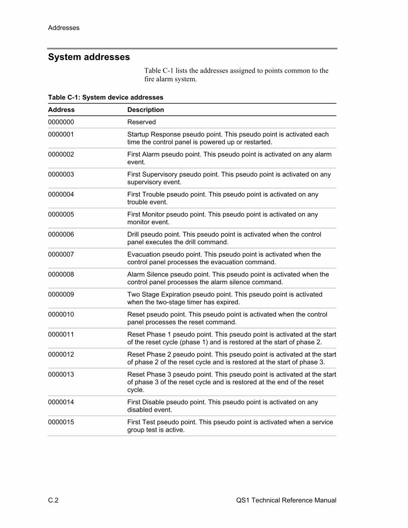
Addresses
C.2 QS1 Technical Reference Manual
System addresses Table C-1 lists the addresses assigned to points common to the fire alarm system.
Table C-1: System device addresses
Address Description
0000000 Reserved
0000001 Startup Response pseudo point. This pseudo point is activated each time the control panel is powered up or restarted.
0000002 First Alarm pseudo point. This pseudo point is activated on any alarm event.
0000003 First Supervisory pseudo point. This pseudo point is activated on any supervisory event.
0000004 First Trouble pseudo point. This pseudo point is activated on any trouble event.
0000005 First Monitor pseudo point. This pseudo point is activated on any monitor event.
0000006 Drill pseudo point. This pseudo point is activated when the control panel executes the drill command.
0000007 Evacuation pseudo point. This pseudo point is activated when the control panel processes the evacuation command.
0000008 Alarm Silence pseudo point. This pseudo point is activated when the control panel processes the alarm silence command.
0000009 Two Stage Expiration pseudo point. This pseudo point is activated when the two-stage timer has expired.
0000010 Reset pseudo point. This pseudo point is activated when the control panel processes the reset command.
0000011 Reset Phase 1 pseudo point. This pseudo point is activated at the start of the reset cycle (phase 1) and is restored at the start of phase 2.
0000012 Reset Phase 2 pseudo point. This pseudo point is activated at the start of phase 2 of the reset cycle and is restored at the start of phase 3.
0000013 Reset Phase 3 pseudo point. This pseudo point is activated at the start of phase 3 of the reset cycle and is restored at the end of the reset cycle.
0000014 First Disable pseudo point. This pseudo point is activated on any disabled event.
0000015 First Test pseudo point. This pseudo point is activated when a service group test is active.

Addresses
QS1 Technical Reference Manual C.3
Table C-1: System device addresses (continued)
Address Description
0000016 Two Stage Timer Started pseudo point. This pseudo point is activated on the first alarm event and is restored when the two-stage timer expires.
0000017 User Trouble pseudo point. This pseudo point is activated when the control panel processes the force trouble command.
0000018 Delayed Output pseudo point. This pseudo point is activated when the control panel processes the cancel delay command.
0016001 to 0016XXX Addresses assigned to LED/switch cards. See Table C-7 through Table C-22.
0017001 to 0017480 Addresses assigned to zones 1 to 480
0018001 to 0018016 Addresses assigned to AND groups 1 to 16
0019001 to 0019064 Addresses assigned to matrix groups 1 to 64
0020001 to 0020129 Addresses assigned to service groups 1 to 129
0021001 to 0021032 Addresses assigned to time controls 1 to 32
0021248 to 0021255 Addresses assigned to the self-test timers for dialer accounts 1 to 8
0022001 to 0022250 Addresses assigned to output groups 1 to 250
0100001 to 0022036 Control panel CPU card addresses (panel 1). See Table C-2.
0101XXX to 0113XXX Addresses assigned to option cards. See Table C-4, and Table C-5.
0114000 to 0114018 Addresses assigned to the DLD card. See Table C-6.
0115000 to 0115024 Addresses assigned to the PS6 card. See Table C-3.
0200001 to 0200036 Remote annunciator CPU card addresses (panel 2). See Table C-2.
0300001 to 0300036 Remote annunciator CPU card addresses (panel 3). See Table C-2.
0400001 to 0400036 Remote annunciator CPU card addresses (panel 4). See Table C-2.
0500001 to 0500036 Remote annunciator CPU card addresses (panel 5). See Table C-2.
0600001 to 0600036 Remote annunciator CPU card addresses (panel 6). See Table C-2.
0700001 to 0700036 Remote annunciator CPU card addresses (panel 7). See Table C-2.
0800001 to 0800036 Remote annunciator CPU card addresses (panel 8). See Table C-2.
0900001 to 0900036 Remote annunciator CPU card addresses (panel 9). See Table C-2.
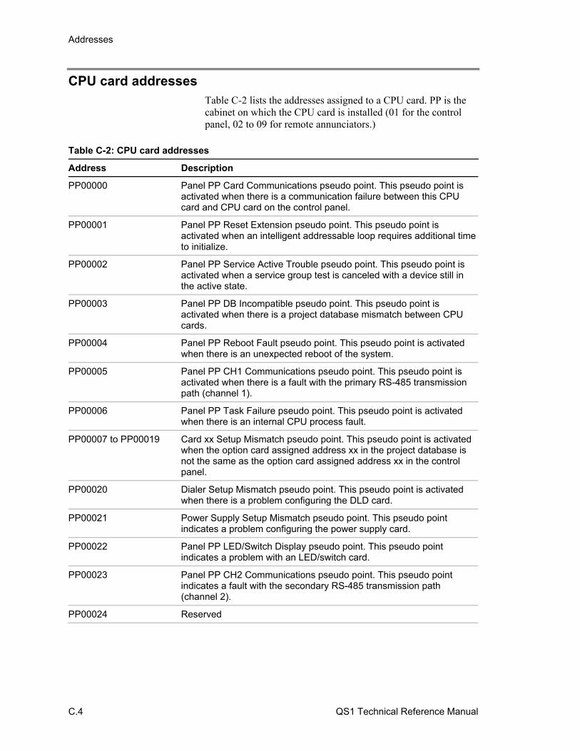
Addresses
C.4 QS1 Technical Reference Manual
CPU card addresses Table C-2 lists the addresses assigned to a CPU card. PP is the cabinet on which the CPU card is installed (01 for the control panel, 02 to 09 for remote annunciators.)
Table C-2: CPU card addresses
Address Description
PP00000 Panel PP Card Communications pseudo point. This pseudo point is activated when there is a communication failure between this CPU card and CPU card on the control panel.
PP00001 Panel PP Reset Extension pseudo point. This pseudo point is activated when an intelligent addressable loop requires additional timeto initialize.
PP00002 Panel PP Service Active Trouble pseudo point. This pseudo point is activated when a service group test is canceled with a device still in the active state.
PP00003 Panel PP DB Incompatible pseudo point. This pseudo point is activated when there is a project database mismatch between CPU cards.
PP00004 Panel PP Reboot Fault pseudo point. This pseudo point is activated when there is an unexpected reboot of the system.
PP00005 Panel PP CH1 Communications pseudo point. This pseudo point is activated when there is a fault with the primary RS-485 transmission path (channel 1).
PP00006 Panel PP Task Failure pseudo point. This pseudo point is activated when there is an internal CPU process fault.
PP00007 to PP00019 Card xx Setup Mismatch pseudo point. This pseudo point is activated when the option card assigned address xx in the project database is not the same as the option card assigned address xx in the control panel.
PP00020 Dialer Setup Mismatch pseudo point. This pseudo point is activated when there is a problem configuring the DLD card.
PP00021 Power Supply Setup Mismatch pseudo point. This pseudo point indicates a problem configuring the power supply card.
PP00022 Panel PP LED/Switch Display pseudo point. This pseudo point indicates a problem with an LED/switch card.
PP00023 Panel PP CH2 Communications pseudo point. This pseudo point indicates a fault with the secondary RS-485 transmission path (channel 2).
PP00024 Reserved
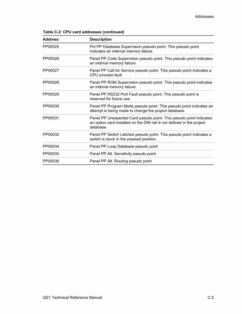
Addresses
QS1 Technical Reference Manual C.5
Table C-2: CPU card addresses (continued)
Address Description
PP00025 Pnl PP Database Supervision pseudo point. This pseudo point indicates an internal memory failure.
PP00026 Panel PP Code Supervision pseudo point. This pseudo point indicates an internal memory failure.
PP00027 Panel PP Call for Service pseudo point. This pseudo point indicates a CPU process fault.
PP00028 Panel PP ROM Supervision pseudo point. This pseudo point indicates an internal memory failure.
PP00029 Panel PP RS232 Port Fault pseudo point. This pseudo point is reserved for future use.
PP00030 Panel PP Program Mode pseudo point. This pseudo point indicates an attempt is being made to change the project database.
PP00031 Panel PP Unexpected Card pseudo point. This pseudo point indicates an option card installed on the DIN rail is not defined in the project database.
PP00032 Panel PP Switch Latched pseudo point. This pseudo point indicates a switch is stuck in the pressed position.
PP00034 Panel PP Loop Database pseudo point
PP00035 Panel PP Alt. Sensitivity pseudo point
PP00036 Panel PP Alt. Routing pseudo point

Addresses
C.6 QS1 Technical Reference Manual
PS6 card addresses Table C-3 lists the addresses assigned to the PS6 card.
Table C-3: PS6 card addresses
Address Description
0115000 Card CC Communications pseudo point. This pseudo point is activated when the control panel can’t communicate with the PS6 card.
0115001 Battery Charger Fault pseudo point. This pseudo point indicates the battery circuit charging voltage is below 20.4 Vdc.
0115002 Battery Wiring or Battery Fault pseudo point. This pseudo point indicates the battery voltage is below 20.4 Vdc.
0115003 AUX Power 1/2 Shorted pseudo point. This pseudo point indicates a short on AUX1 or AUX2.
0115004 Thermal Fault pseudo point. Reserved for future use.
0115005 AUX Power 3 Shorted pseudo point. This pseudo point indicates a short on AUX3.
0115006 Smoke Power Shorted pseudo point. This pseudo point indicates when the smoke/accessory power output is shorted.
0115007 Primary AC Power Failure pseudo point. This pseudo point indicates that the control panel has lost mains power.
0115008 Excessive Battery Current pseudo point. This pseudo point indicates an over current condition while operating on standby power.
0115009 Check System Wiring pseudo point. This pseudo point indicates the presence of an earth ground fault in the system wiring.
0115010 Power Supply RAM Supervision pseudo point. This pseudo point indicates an internal memory fault.
0115011 Power Supply ROM Supervision pseudo point. This pseudo point indicates an internal memory fault.
0115012 Power Supply EEPROM Supervision pseudo point. This pseudo point indicates an internal memory fault.
0115013 to 0115020 Not used
0115021 Power Supply User Relay (programmable)
0115022 Power Supply Trouble Relay (not programmable)
0115023 Power Supply Supv Relay (not programmable)
0115024 Power Supply Alarm Relay (not programmable)
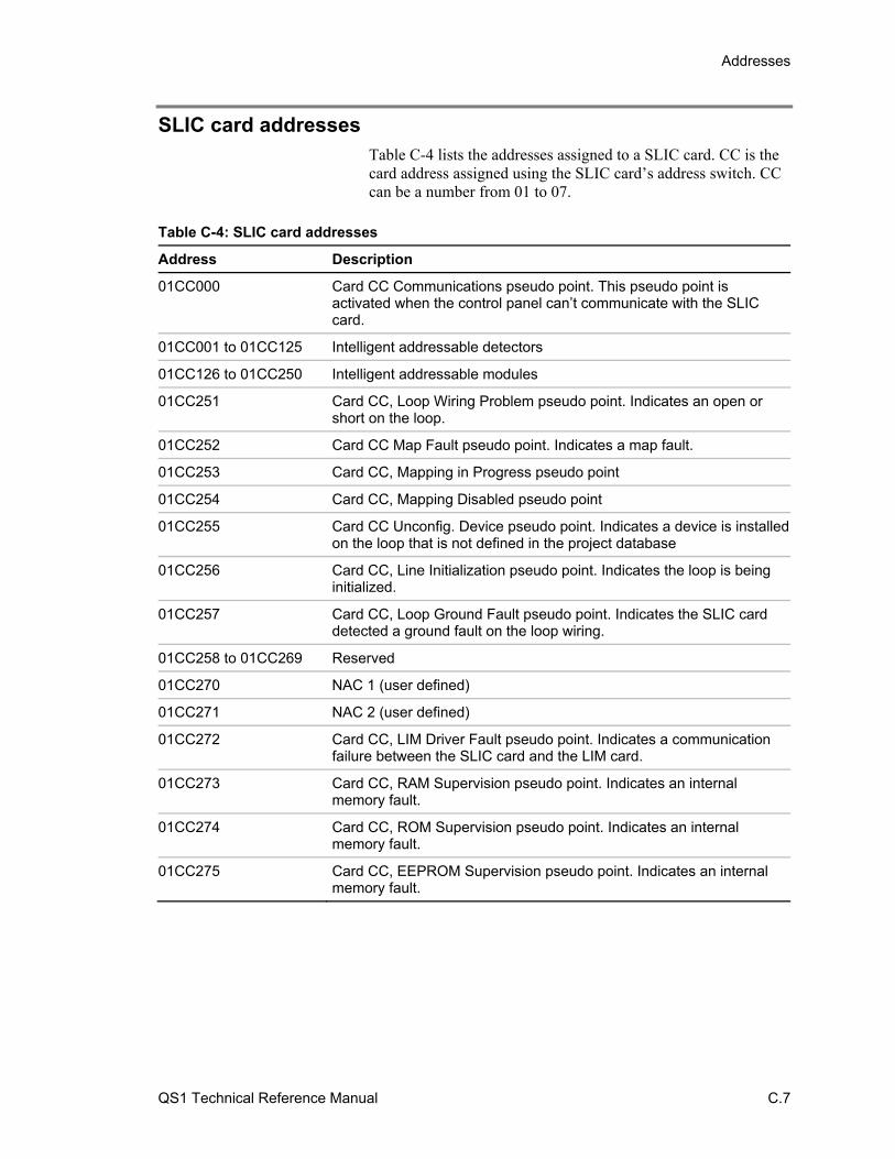
Addresses
QS1 Technical Reference Manual C.7
SLIC card addresses Table C-4 lists the addresses assigned to a SLIC card. CC is the card address assigned using the SLIC card’s address switch. CC can be a number from 01 to 07.
Table C-4: SLIC card addresses
Address Description
01CC000 Card CC Communications pseudo point. This pseudo point is activated when the control panel can’t communicate with the SLIC card.
01CC001 to 01CC125 Intelligent addressable detectors
01CC126 to 01CC250 Intelligent addressable modules
01CC251 Card CC, Loop Wiring Problem pseudo point. Indicates an open or short on the loop.
01CC252 Card CC Map Fault pseudo point. Indicates a map fault.
01CC253 Card CC, Mapping in Progress pseudo point
01CC254 Card CC, Mapping Disabled pseudo point
01CC255 Card CC Unconfig. Device pseudo point. Indicates a device is installed on the loop that is not defined in the project database
01CC256 Card CC, Line Initialization pseudo point. Indicates the loop is being initialized.
01CC257 Card CC, Loop Ground Fault pseudo point. Indicates the SLIC card detected a ground fault on the loop wiring.
01CC258 to 01CC269 Reserved
01CC270 NAC 1 (user defined)
01CC271 NAC 2 (user defined)
01CC272 Card CC, LIM Driver Fault pseudo point. Indicates a communication failure between the SLIC card and the LIM card.
01CC273 Card CC, RAM Supervision pseudo point. Indicates an internal memory fault.
01CC274 Card CC, ROM Supervision pseudo point. Indicates an internal memory fault.
01CC275 Card CC, EEPROM Supervision pseudo point. Indicates an internal memory fault.
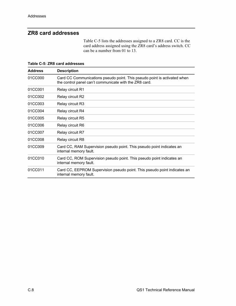
Addresses
C.8 QS1 Technical Reference Manual
ZR8 card addresses Table C-5 lists the addresses assigned to a ZR8 card. CC is the card address assigned using the ZR8 card’s address switch. CC can be a number from 01 to 13.
Table C-5: ZR8 card addresses
Address Description
01CC000 Card CC Communications pseudo point. This pseudo point is activated when the control panel can’t communicate with the ZR8 card.
01CC001 Relay circuit R1
01CC002 Relay circuit R2
01CC003 Relay circuit R3
01CC004 Relay circuit R4
01CC005 Relay circuit R5
01CC006 Relay circuit R6
01CC007 Relay circuit R7
01CC008 Relay circuit R8
01CC009 Card CC, RAM Supervision pseudo point. This pseudo point indicates an internal memory fault.
01CC010 Card CC, ROM Supervision pseudo point. This pseudo point indicates an internal memory fault.
01CC011 Card CC, EEPROM Supervision pseudo point. This pseudo point indicates an internal memory fault.
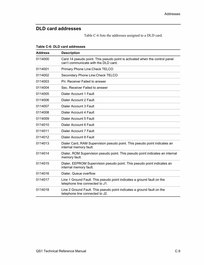
Addresses
QS1 Technical Reference Manual C.9
DLD card addresses Table C-6 lists the addresses assigned to a DLD card.
Table C-6: DLD card addresses
Address Description
0114000 Card 14 pseudo point. This pseudo point is activated when the control panel can’t communicate with the DLD card.
0114001 Primary Phone Line:Check TELCO
0114002 Secondary Phone Line:Check TELCO
0114003 Pri. Receiver Failed to answer
0114004 Sec. Receiver Failed to answer
0114005 Dialer Account 1 Fault
0114006 Dialer Account 2 Fault
0114007 Dialer Account 3 Fault
0114008 Dialer Account 4 Fault
0114009 Dialer Account 5 Fault
0114010 Dialer Account 6 Fault
0114011 Dialer Account 7 Fault
0114012 Dialer Account 8 Fault
0114013 Dialer Card, RAM Supervision pseudo point. This pseudo point indicates an internal memory fault.
0114014 Dialer, ROM Supervision pseudo point. This pseudo point indicates an internal memory fault.
0114015 Dialer, EEPROM Supervision pseudo point. This pseudo point indicates an internal memory fault.
0114016 Dialer, Queue overflow
0114017 Line 1 Ground Fault. This pseudo point indicates a ground fault on the telephone line connected to J1.
0114018 Line 2 Ground Fault. This pseudo point indicates a ground fault on the telephone line connected to J2.
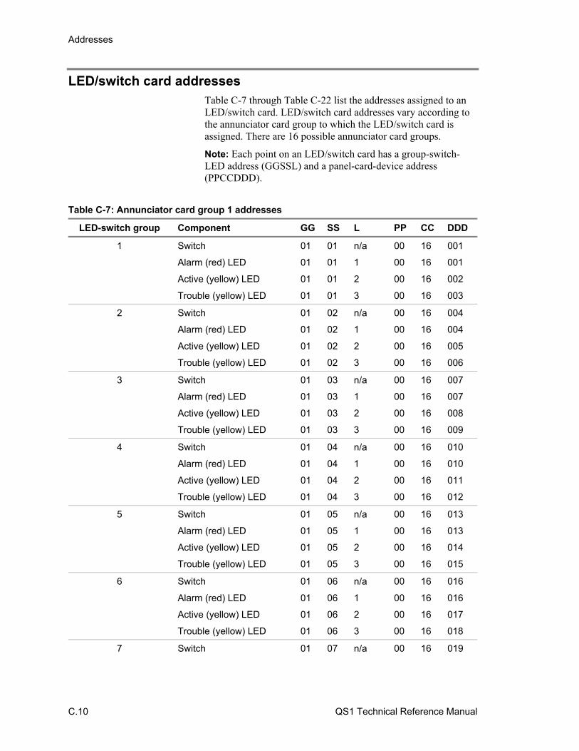
Addresses
C.10 QS1 Technical Reference Manual
LED/switch card addresses Table C-7 through Table C-22 list the addresses assigned to an LED/switch card. LED/switch card addresses vary according to the annunciator card group to which the LED/switch card is assigned. There are 16 possible annunciator card groups.
Note: Each point on an LED/switch card has a group-switch-LED address (GGSSL) and a panel-card-device address (PPCCDDD).
Table C-7: Annunciator card group 1 addresses
LED-switch group Component GG SS L PP CC DDD
1 Switch 01 01 n/a 00 16 001
Alarm (red) LED 01 01 1 00 16 001
Active (yellow) LED 01 01 2 00 16 002
Trouble (yellow) LED 01 01 3 00 16 003
2 Switch 01 02 n/a 00 16 004
Alarm (red) LED 01 02 1 00 16 004
Active (yellow) LED 01 02 2 00 16 005
Trouble (yellow) LED 01 02 3 00 16 006
3 Switch 01 03 n/a 00 16 007
Alarm (red) LED 01 03 1 00 16 007
Active (yellow) LED 01 03 2 00 16 008
Trouble (yellow) LED 01 03 3 00 16 009
4 Switch 01 04 n/a 00 16 010
Alarm (red) LED 01 04 1 00 16 010
Active (yellow) LED 01 04 2 00 16 011
Trouble (yellow) LED 01 04 3 00 16 012
5 Switch 01 05 n/a 00 16 013
Alarm (red) LED 01 05 1 00 16 013
Active (yellow) LED 01 05 2 00 16 014
Trouble (yellow) LED 01 05 3 00 16 015
6 Switch 01 06 n/a 00 16 016
Alarm (red) LED 01 06 1 00 16 016
Active (yellow) LED 01 06 2 00 16 017
Trouble (yellow) LED 01 06 3 00 16 018
7 Switch 01 07 n/a 00 16 019
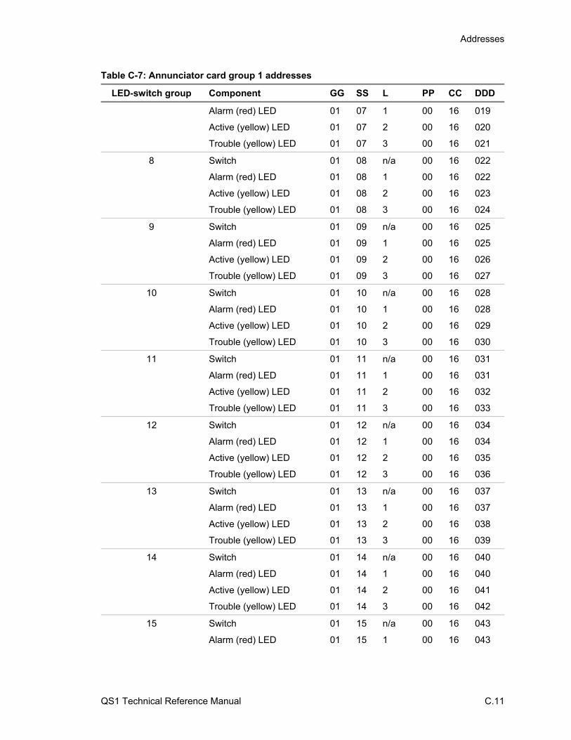
Addresses
QS1 Technical Reference Manual C.11
Table C-7: Annunciator card group 1 addresses
LED-switch group Component GG SS L PP CC DDD
Alarm (red) LED 01 07 1 00 16 019
Active (yellow) LED 01 07 2 00 16 020
Trouble (yellow) LED 01 07 3 00 16 021
8 Switch 01 08 n/a 00 16 022
Alarm (red) LED 01 08 1 00 16 022
Active (yellow) LED 01 08 2 00 16 023
Trouble (yellow) LED 01 08 3 00 16 024
9 Switch 01 09 n/a 00 16 025
Alarm (red) LED 01 09 1 00 16 025
Active (yellow) LED 01 09 2 00 16 026
Trouble (yellow) LED 01 09 3 00 16 027
10 Switch 01 10 n/a 00 16 028
Alarm (red) LED 01 10 1 00 16 028
Active (yellow) LED 01 10 2 00 16 029
Trouble (yellow) LED 01 10 3 00 16 030
11 Switch 01 11 n/a 00 16 031
Alarm (red) LED 01 11 1 00 16 031
Active (yellow) LED 01 11 2 00 16 032
Trouble (yellow) LED 01 11 3 00 16 033
12 Switch 01 12 n/a 00 16 034
Alarm (red) LED 01 12 1 00 16 034
Active (yellow) LED 01 12 2 00 16 035
Trouble (yellow) LED 01 12 3 00 16 036
13 Switch 01 13 n/a 00 16 037
Alarm (red) LED 01 13 1 00 16 037
Active (yellow) LED 01 13 2 00 16 038
Trouble (yellow) LED 01 13 3 00 16 039
14 Switch 01 14 n/a 00 16 040
Alarm (red) LED 01 14 1 00 16 040
Active (yellow) LED 01 14 2 00 16 041
Trouble (yellow) LED 01 14 3 00 16 042
15 Switch 01 15 n/a 00 16 043
Alarm (red) LED 01 15 1 00 16 043
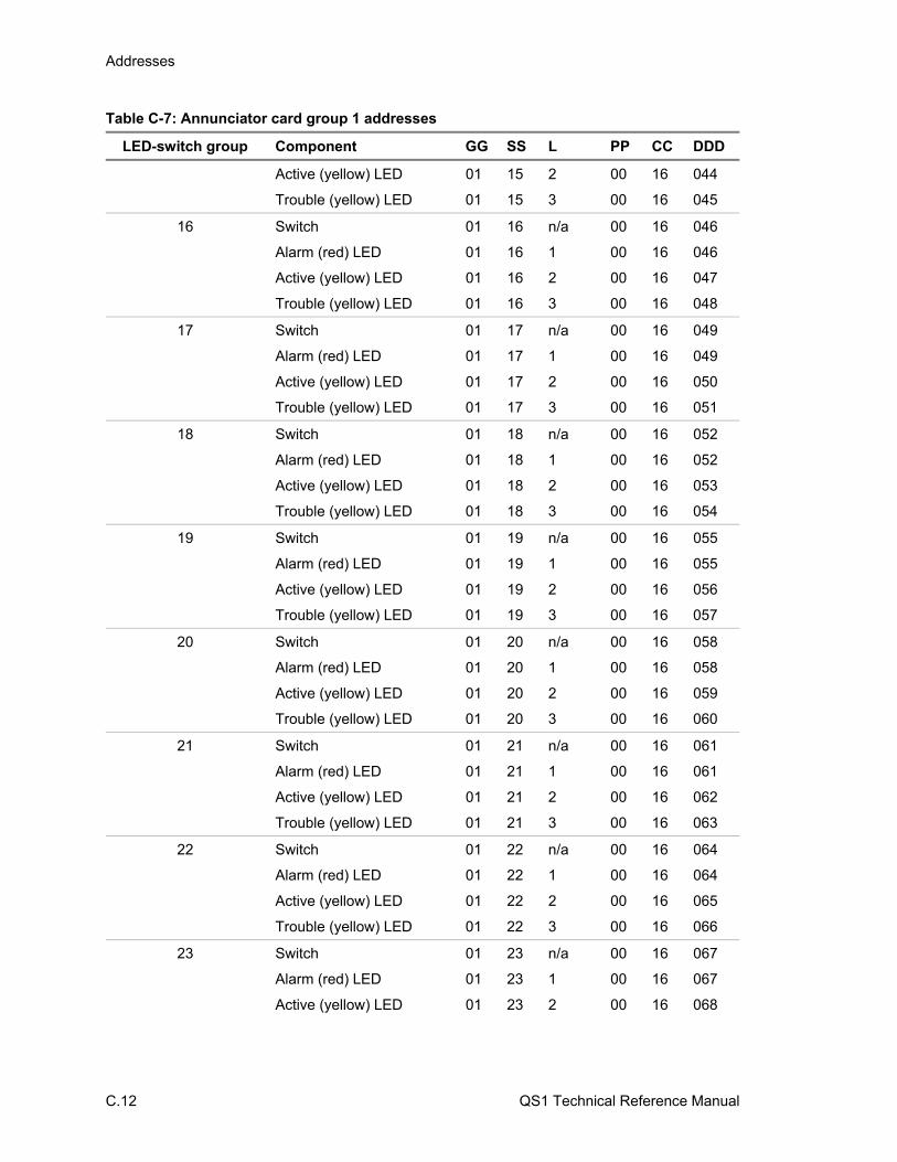
Addresses
C.12 QS1 Technical Reference Manual
Table C-7: Annunciator card group 1 addresses
LED-switch group Component GG SS L PP CC DDD
Active (yellow) LED 01 15 2 00 16 044
Trouble (yellow) LED 01 15 3 00 16 045
16 Switch 01 16 n/a 00 16 046
Alarm (red) LED 01 16 1 00 16 046
Active (yellow) LED 01 16 2 00 16 047
Trouble (yellow) LED 01 16 3 00 16 048
17 Switch 01 17 n/a 00 16 049
Alarm (red) LED 01 17 1 00 16 049
Active (yellow) LED 01 17 2 00 16 050
Trouble (yellow) LED 01 17 3 00 16 051
18 Switch 01 18 n/a 00 16 052
Alarm (red) LED 01 18 1 00 16 052
Active (yellow) LED 01 18 2 00 16 053
Trouble (yellow) LED 01 18 3 00 16 054
19 Switch 01 19 n/a 00 16 055
Alarm (red) LED 01 19 1 00 16 055
Active (yellow) LED 01 19 2 00 16 056
Trouble (yellow) LED 01 19 3 00 16 057
20 Switch 01 20 n/a 00 16 058
Alarm (red) LED 01 20 1 00 16 058
Active (yellow) LED 01 20 2 00 16 059
Trouble (yellow) LED 01 20 3 00 16 060
21 Switch 01 21 n/a 00 16 061
Alarm (red) LED 01 21 1 00 16 061
Active (yellow) LED 01 21 2 00 16 062
Trouble (yellow) LED 01 21 3 00 16 063
22 Switch 01 22 n/a 00 16 064
Alarm (red) LED 01 22 1 00 16 064
Active (yellow) LED 01 22 2 00 16 065
Trouble (yellow) LED 01 22 3 00 16 066
23 Switch 01 23 n/a 00 16 067
Alarm (red) LED 01 23 1 00 16 067
Active (yellow) LED 01 23 2 00 16 068
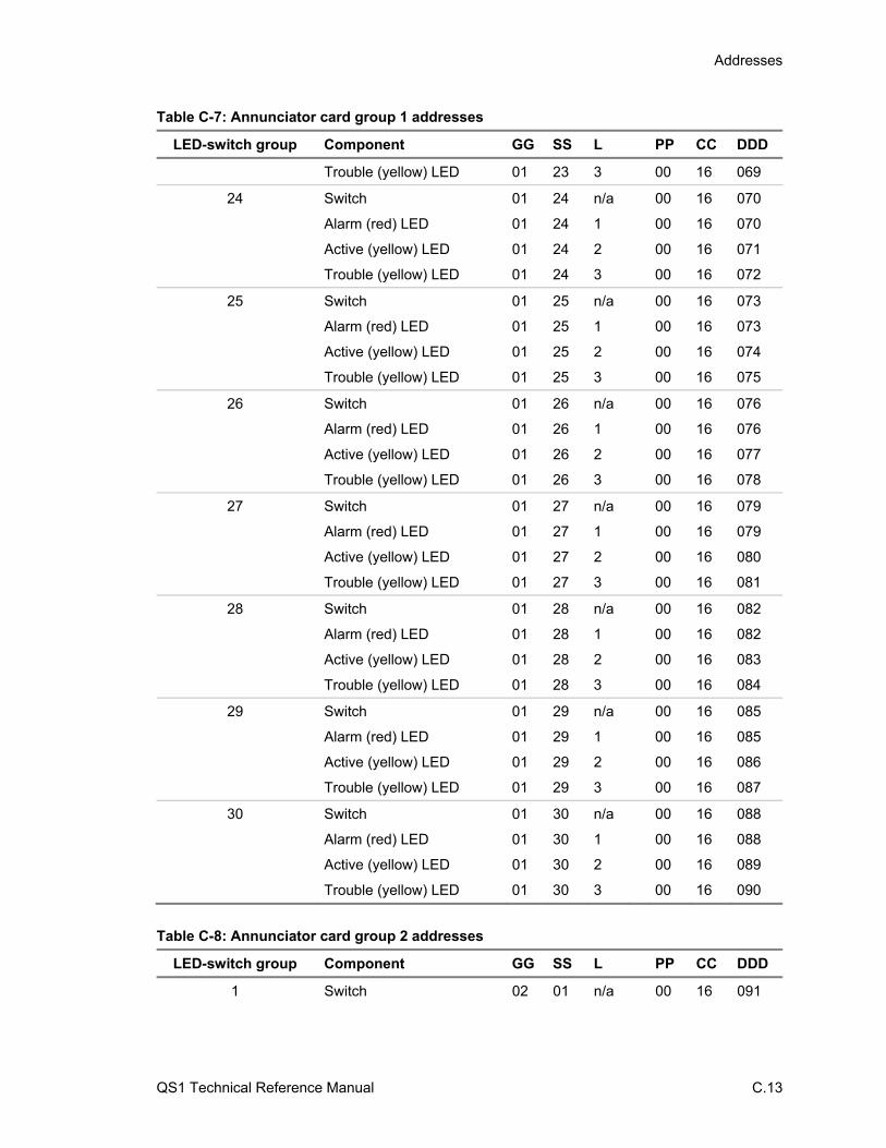
Addresses
QS1 Technical Reference Manual C.13
Table C-7: Annunciator card group 1 addresses
LED-switch group Component GG SS L PP CC DDD
Trouble (yellow) LED 01 23 3 00 16 069
24 Switch 01 24 n/a 00 16 070
Alarm (red) LED 01 24 1 00 16 070
Active (yellow) LED 01 24 2 00 16 071
Trouble (yellow) LED 01 24 3 00 16 072
25 Switch 01 25 n/a 00 16 073
Alarm (red) LED 01 25 1 00 16 073
Active (yellow) LED 01 25 2 00 16 074
Trouble (yellow) LED 01 25 3 00 16 075
26 Switch 01 26 n/a 00 16 076
Alarm (red) LED 01 26 1 00 16 076
Active (yellow) LED 01 26 2 00 16 077
Trouble (yellow) LED 01 26 3 00 16 078
27 Switch 01 27 n/a 00 16 079
Alarm (red) LED 01 27 1 00 16 079
Active (yellow) LED 01 27 2 00 16 080
Trouble (yellow) LED 01 27 3 00 16 081
28 Switch 01 28 n/a 00 16 082
Alarm (red) LED 01 28 1 00 16 082
Active (yellow) LED 01 28 2 00 16 083
Trouble (yellow) LED 01 28 3 00 16 084
29 Switch 01 29 n/a 00 16 085
Alarm (red) LED 01 29 1 00 16 085
Active (yellow) LED 01 29 2 00 16 086
Trouble (yellow) LED 01 29 3 00 16 087
30 Switch 01 30 n/a 00 16 088
Alarm (red) LED 01 30 1 00 16 088
Active (yellow) LED 01 30 2 00 16 089
Trouble (yellow) LED 01 30 3 00 16 090
Table C-8: Annunciator card group 2 addresses
LED-switch group Component GG SS L PP CC DDD
1 Switch 02 01 n/a 00 16 091

Addresses
C.14 QS1 Technical Reference Manual
Table C-8: Annunciator card group 2 addresses
LED-switch group Component GG SS L PP CC DDD
Alarm (red) LED 02 01 1 00 16 091
Active (yellow) LED 02 01 2 00 16 092
Trouble (yellow) LED 02 01 3 00 16 093
2 Switch 02 02 n/a 00 16 094
Alarm (red) LED 02 02 1 00 16 094
Active (yellow) LED 02 02 2 00 16 095
Trouble (yellow) LED 02 02 3 00 16 096
3 Switch 02 03 n/a 00 16 097
Alarm (red) LED 02 03 1 00 16 097
Active (yellow) LED 02 03 2 00 16 098
Trouble (yellow) LED 02 03 3 00 16 099
4 Switch 02 04 n/a 00 16 100
Alarm (red) LED 02 04 1 00 16 100
Active (yellow) LED 02 04 2 00 16 101
Trouble (yellow) LED 02 04 3 00 16 102
5 Switch 02 05 n/a 00 16 103
Alarm (red) LED 02 05 1 00 16 103
Active (yellow) LED 02 05 2 00 16 104
Trouble (yellow) LED 02 05 3 00 16 105
6 Switch 02 06 n/a 00 16 106
Alarm (red) LED 02 06 1 00 16 106
Active (yellow) LED 02 06 2 00 16 107
Trouble (yellow) LED 02 06 3 00 16 108
7 Switch 02 07 n/a 00 16 109
Alarm (red) LED 02 07 1 00 16 109
Active (yellow) LED 02 07 2 00 16 110
Trouble (yellow) LED 02 07 3 00 16 111
8 Switch 02 08 n/a 00 16 112
Alarm (red) LED 02 08 1 00 16 112
Active (yellow) LED 02 08 2 00 16 113
Trouble (yellow) LED 02 08 3 00 16 114
9 Switch 02 09 n/a 00 16 115
Alarm (red) LED 02 09 1 00 16 115
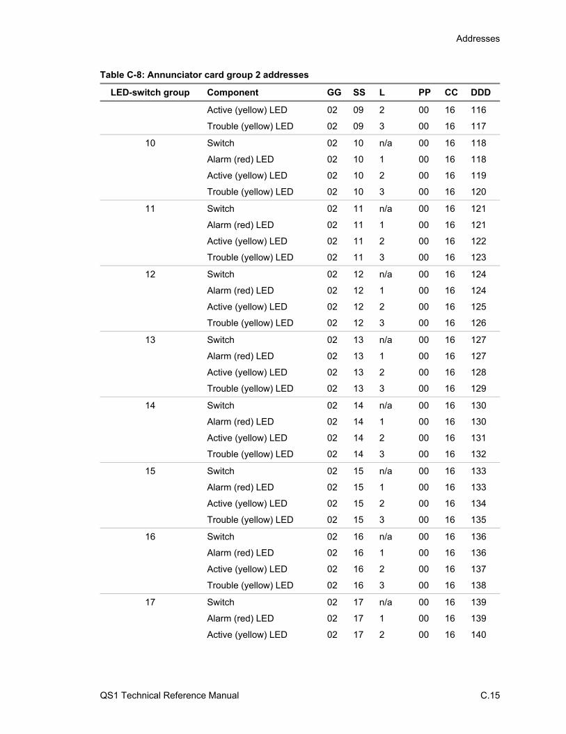
Addresses
QS1 Technical Reference Manual C.15
Table C-8: Annunciator card group 2 addresses
LED-switch group Component GG SS L PP CC DDD
Active (yellow) LED 02 09 2 00 16 116
Trouble (yellow) LED 02 09 3 00 16 117
10 Switch 02 10 n/a 00 16 118
Alarm (red) LED 02 10 1 00 16 118
Active (yellow) LED 02 10 2 00 16 119
Trouble (yellow) LED 02 10 3 00 16 120
11 Switch 02 11 n/a 00 16 121
Alarm (red) LED 02 11 1 00 16 121
Active (yellow) LED 02 11 2 00 16 122
Trouble (yellow) LED 02 11 3 00 16 123
12 Switch 02 12 n/a 00 16 124
Alarm (red) LED 02 12 1 00 16 124
Active (yellow) LED 02 12 2 00 16 125
Trouble (yellow) LED 02 12 3 00 16 126
13 Switch 02 13 n/a 00 16 127
Alarm (red) LED 02 13 1 00 16 127
Active (yellow) LED 02 13 2 00 16 128
Trouble (yellow) LED 02 13 3 00 16 129
14 Switch 02 14 n/a 00 16 130
Alarm (red) LED 02 14 1 00 16 130
Active (yellow) LED 02 14 2 00 16 131
Trouble (yellow) LED 02 14 3 00 16 132
15 Switch 02 15 n/a 00 16 133
Alarm (red) LED 02 15 1 00 16 133
Active (yellow) LED 02 15 2 00 16 134
Trouble (yellow) LED 02 15 3 00 16 135
16 Switch 02 16 n/a 00 16 136
Alarm (red) LED 02 16 1 00 16 136
Active (yellow) LED 02 16 2 00 16 137
Trouble (yellow) LED 02 16 3 00 16 138
17 Switch 02 17 n/a 00 16 139
Alarm (red) LED 02 17 1 00 16 139
Active (yellow) LED 02 17 2 00 16 140
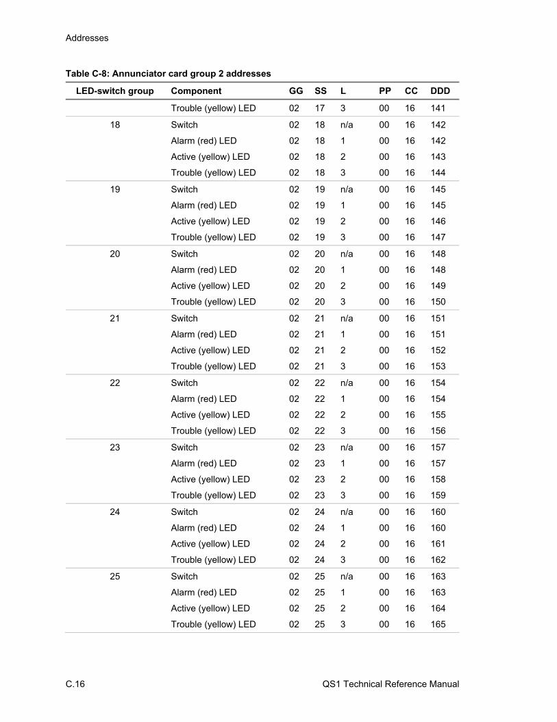
Addresses
C.16 QS1 Technical Reference Manual
Table C-8: Annunciator card group 2 addresses
LED-switch group Component GG SS L PP CC DDD
Trouble (yellow) LED 02 17 3 00 16 141
18 Switch 02 18 n/a 00 16 142
Alarm (red) LED 02 18 1 00 16 142
Active (yellow) LED 02 18 2 00 16 143
Trouble (yellow) LED 02 18 3 00 16 144
19 Switch 02 19 n/a 00 16 145
Alarm (red) LED 02 19 1 00 16 145
Active (yellow) LED 02 19 2 00 16 146
Trouble (yellow) LED 02 19 3 00 16 147
20 Switch 02 20 n/a 00 16 148
Alarm (red) LED 02 20 1 00 16 148
Active (yellow) LED 02 20 2 00 16 149
Trouble (yellow) LED 02 20 3 00 16 150
21 Switch 02 21 n/a 00 16 151
Alarm (red) LED 02 21 1 00 16 151
Active (yellow) LED 02 21 2 00 16 152
Trouble (yellow) LED 02 21 3 00 16 153
22 Switch 02 22 n/a 00 16 154
Alarm (red) LED 02 22 1 00 16 154
Active (yellow) LED 02 22 2 00 16 155
Trouble (yellow) LED 02 22 3 00 16 156
23 Switch 02 23 n/a 00 16 157
Alarm (red) LED 02 23 1 00 16 157
Active (yellow) LED 02 23 2 00 16 158
Trouble (yellow) LED 02 23 3 00 16 159
24 Switch 02 24 n/a 00 16 160
Alarm (red) LED 02 24 1 00 16 160
Active (yellow) LED 02 24 2 00 16 161
Trouble (yellow) LED 02 24 3 00 16 162
25 Switch 02 25 n/a 00 16 163
Alarm (red) LED 02 25 1 00 16 163
Active (yellow) LED 02 25 2 00 16 164
Trouble (yellow) LED 02 25 3 00 16 165
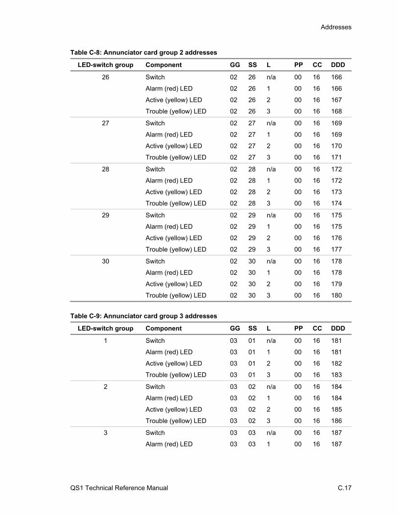
Addresses
QS1 Technical Reference Manual C.17
Table C-8: Annunciator card group 2 addresses
LED-switch group Component GG SS L PP CC DDD
26 Switch 02 26 n/a 00 16 166
Alarm (red) LED 02 26 1 00 16 166
Active (yellow) LED 02 26 2 00 16 167
Trouble (yellow) LED 02 26 3 00 16 168
27 Switch 02 27 n/a 00 16 169
Alarm (red) LED 02 27 1 00 16 169
Active (yellow) LED 02 27 2 00 16 170
Trouble (yellow) LED 02 27 3 00 16 171
28 Switch 02 28 n/a 00 16 172
Alarm (red) LED 02 28 1 00 16 172
Active (yellow) LED 02 28 2 00 16 173
Trouble (yellow) LED 02 28 3 00 16 174
29 Switch 02 29 n/a 00 16 175
Alarm (red) LED 02 29 1 00 16 175
Active (yellow) LED 02 29 2 00 16 176
Trouble (yellow) LED 02 29 3 00 16 177
30 Switch 02 30 n/a 00 16 178
Alarm (red) LED 02 30 1 00 16 178
Active (yellow) LED 02 30 2 00 16 179
Trouble (yellow) LED 02 30 3 00 16 180
Table C-9: Annunciator card group 3 addresses
LED-switch group Component GG SS L PP CC DDD
1 Switch 03 01 n/a 00 16 181
Alarm (red) LED 03 01 1 00 16 181
Active (yellow) LED 03 01 2 00 16 182
Trouble (yellow) LED 03 01 3 00 16 183
2 Switch 03 02 n/a 00 16 184
Alarm (red) LED 03 02 1 00 16 184
Active (yellow) LED 03 02 2 00 16 185
Trouble (yellow) LED 03 02 3 00 16 186
3 Switch 03 03 n/a 00 16 187
Alarm (red) LED 03 03 1 00 16 187
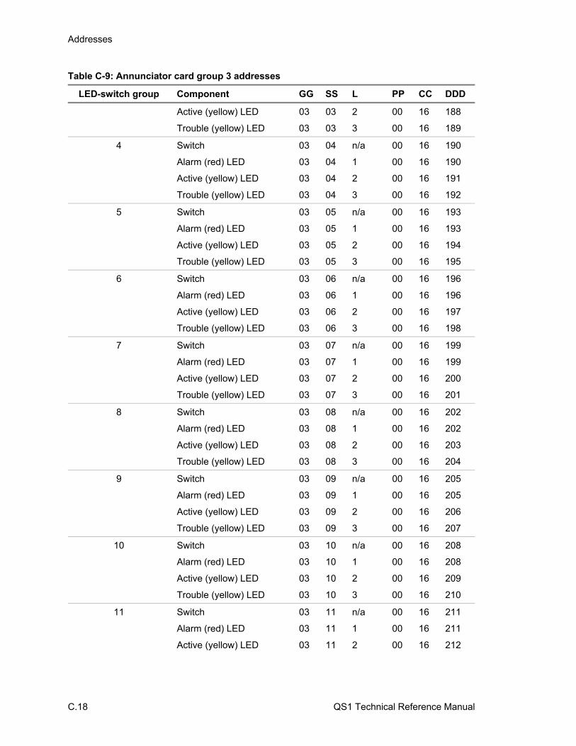
Addresses
C.18 QS1 Technical Reference Manual
Table C-9: Annunciator card group 3 addresses
LED-switch group Component GG SS L PP CC DDD
Active (yellow) LED 03 03 2 00 16 188
Trouble (yellow) LED 03 03 3 00 16 189
4 Switch 03 04 n/a 00 16 190
Alarm (red) LED 03 04 1 00 16 190
Active (yellow) LED 03 04 2 00 16 191
Trouble (yellow) LED 03 04 3 00 16 192
5 Switch 03 05 n/a 00 16 193
Alarm (red) LED 03 05 1 00 16 193
Active (yellow) LED 03 05 2 00 16 194
Trouble (yellow) LED 03 05 3 00 16 195
6 Switch 03 06 n/a 00 16 196
Alarm (red) LED 03 06 1 00 16 196
Active (yellow) LED 03 06 2 00 16 197
Trouble (yellow) LED 03 06 3 00 16 198
7 Switch 03 07 n/a 00 16 199
Alarm (red) LED 03 07 1 00 16 199
Active (yellow) LED 03 07 2 00 16 200
Trouble (yellow) LED 03 07 3 00 16 201
8 Switch 03 08 n/a 00 16 202
Alarm (red) LED 03 08 1 00 16 202
Active (yellow) LED 03 08 2 00 16 203
Trouble (yellow) LED 03 08 3 00 16 204
9 Switch 03 09 n/a 00 16 205
Alarm (red) LED 03 09 1 00 16 205
Active (yellow) LED 03 09 2 00 16 206
Trouble (yellow) LED 03 09 3 00 16 207
10 Switch 03 10 n/a 00 16 208
Alarm (red) LED 03 10 1 00 16 208
Active (yellow) LED 03 10 2 00 16 209
Trouble (yellow) LED 03 10 3 00 16 210
11 Switch 03 11 n/a 00 16 211
Alarm (red) LED 03 11 1 00 16 211
Active (yellow) LED 03 11 2 00 16 212

Addresses
QS1 Technical Reference Manual C.19
Table C-9: Annunciator card group 3 addresses
LED-switch group Component GG SS L PP CC DDD
Trouble (yellow) LED 03 11 3 00 16 213
12 Switch 03 12 n/a 00 16 214
Alarm (red) LED 03 12 1 00 16 214
Active (yellow) LED 03 12 2 00 16 215
Trouble (yellow) LED 03 12 3 00 16 216
13 Switch 03 13 n/a 00 16 217
Alarm (red) LED 03 13 1 00 16 217
Active (yellow) LED 03 13 2 00 16 218
Trouble (yellow) LED 03 13 3 00 16 219
14 Switch 03 14 n/a 00 16 220
Alarm (red) LED 03 14 1 00 16 220
Active (yellow) LED 03 14 2 00 16 221
Trouble (yellow) LED 03 14 3 00 16 222
15 Switch 03 15 n/a 00 16 223
Alarm (red) LED 03 15 1 00 16 223
Active (yellow) LED 03 15 2 00 16 224
Trouble (yellow) LED 03 15 3 00 16 225
16 Switch 03 16 n/a 00 16 226
Alarm (red) LED 03 16 1 00 16 226
Active (yellow) LED 03 16 2 00 16 227
Trouble (yellow) LED 03 16 3 00 16 228
17 Switch 03 17 n/a 00 16 229
Alarm (red) LED 03 17 1 00 16 229
Active (yellow) LED 03 17 2 00 16 230
Trouble (yellow) LED 03 17 3 00 16 231
18 Switch 03 18 n/a 00 16 232
Alarm (red) LED 03 18 1 00 16 232
Active (yellow) LED 03 18 2 00 16 233
Trouble (yellow) LED 03 18 3 00 16 234
19 Switch 03 19 n/a 00 16 235
Alarm (red) LED 03 19 1 00 16 235
Active (yellow) LED 03 19 2 00 16 236
Trouble (yellow) LED 03 19 3 00 16 237

Addresses
C.20 QS1 Technical Reference Manual
Table C-9: Annunciator card group 3 addresses
LED-switch group Component GG SS L PP CC DDD
20 Switch 03 20 n/a 00 16 238
Alarm (red) LED 03 20 1 00 16 238
Active (yellow) LED 03 20 2 00 16 239
Trouble (yellow) LED 03 20 3 00 16 240
21 Switch 03 21 n/a 00 16 241
Alarm (red) LED 03 21 1 00 16 241
Active (yellow) LED 03 21 2 00 16 242
Trouble (yellow) LED 03 21 3 00 16 243
22 Switch 03 22 n/a 00 16 244
Alarm (red) LED 03 22 1 00 16 244
Active (yellow) LED 03 22 2 00 16 245
Trouble (yellow) LED 03 22 3 00 16 246
23 Switch 03 23 n/a 00 16 247
Alarm (red) LED 03 23 1 00 16 247
Active (yellow) LED 03 23 2 00 16 248
Trouble (yellow) LED 03 23 3 00 16 249
24 Switch 03 24 n/a 00 16 250
Alarm (red) LED 03 24 1 00 16 250
Active (yellow) LED 03 24 2 00 16 251
Trouble (yellow) LED 03 24 3 00 16 252
25 Switch 03 25 n/a 00 16 253
Alarm (red) LED 03 25 1 00 16 253
Active (yellow) LED 03 25 2 00 16 254
Trouble (yellow) LED 03 25 3 00 16 255
26 Switch 03 26 n/a 00 16 256
Alarm (red) LED 03 26 1 00 16 256
Active (yellow) LED 03 26 2 00 16 257
Trouble (yellow) LED 03 26 3 00 16 258
27 Switch 03 27 n/a 00 16 259
Alarm (red) LED 03 27 1 00 16 259
Active (yellow) LED 03 27 2 00 16 260
Trouble (yellow) LED 03 27 3 00 16 261
28 Switch 03 28 n/a 00 16 262
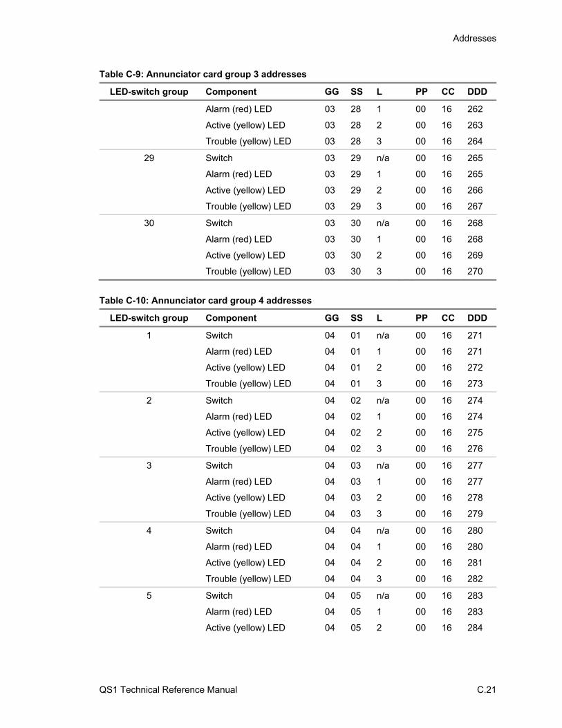
Addresses
QS1 Technical Reference Manual C.21
Table C-9: Annunciator card group 3 addresses
LED-switch group Component GG SS L PP CC DDD
Alarm (red) LED 03 28 1 00 16 262
Active (yellow) LED 03 28 2 00 16 263
Trouble (yellow) LED 03 28 3 00 16 264
29 Switch 03 29 n/a 00 16 265
Alarm (red) LED 03 29 1 00 16 265
Active (yellow) LED 03 29 2 00 16 266
Trouble (yellow) LED 03 29 3 00 16 267
30 Switch 03 30 n/a 00 16 268
Alarm (red) LED 03 30 1 00 16 268
Active (yellow) LED 03 30 2 00 16 269
Trouble (yellow) LED 03 30 3 00 16 270
Table C-10: Annunciator card group 4 addresses
LED-switch group Component GG SS L PP CC DDD
1 Switch 04 01 n/a 00 16 271
Alarm (red) LED 04 01 1 00 16 271
Active (yellow) LED 04 01 2 00 16 272
Trouble (yellow) LED 04 01 3 00 16 273
2 Switch 04 02 n/a 00 16 274
Alarm (red) LED 04 02 1 00 16 274
Active (yellow) LED 04 02 2 00 16 275
Trouble (yellow) LED 04 02 3 00 16 276
3 Switch 04 03 n/a 00 16 277
Alarm (red) LED 04 03 1 00 16 277
Active (yellow) LED 04 03 2 00 16 278
Trouble (yellow) LED 04 03 3 00 16 279
4 Switch 04 04 n/a 00 16 280
Alarm (red) LED 04 04 1 00 16 280
Active (yellow) LED 04 04 2 00 16 281
Trouble (yellow) LED 04 04 3 00 16 282
5 Switch 04 05 n/a 00 16 283
Alarm (red) LED 04 05 1 00 16 283
Active (yellow) LED 04 05 2 00 16 284
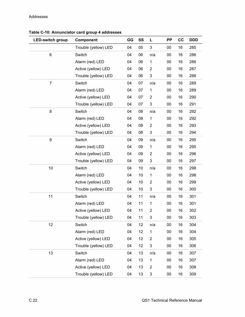
Addresses
C.22 QS1 Technical Reference Manual
Table C-10: Annunciator card group 4 addresses
LED-switch group Component GG SS L PP CC DDD
Trouble (yellow) LED 04 05 3 00 16 285
6 Switch 04 06 n/a 00 16 286
Alarm (red) LED 04 06 1 00 16 286
Active (yellow) LED 04 06 2 00 16 287
Trouble (yellow) LED 04 06 3 00 16 288
7 Switch 04 07 n/a 00 16 289
Alarm (red) LED 04 07 1 00 16 289
Active (yellow) LED 04 07 2 00 16 290
Trouble (yellow) LED 04 07 3 00 16 291
8 Switch 04 08 n/a 00 16 292
Alarm (red) LED 04 08 1 00 16 292
Active (yellow) LED 04 08 2 00 16 293
Trouble (yellow) LED 04 08 3 00 16 294
9 Switch 04 09 n/a 00 16 295
Alarm (red) LED 04 09 1 00 16 295
Active (yellow) LED 04 09 2 00 16 296
Trouble (yellow) LED 04 09 3 00 16 297
10 Switch 04 10 n/a 00 16 298
Alarm (red) LED 04 10 1 00 16 298
Active (yellow) LED 04 10 2 00 16 299
Trouble (yellow) LED 04 10 3 00 16 300
11 Switch 04 11 n/a 00 16 301
Alarm (red) LED 04 11 1 00 16 301
Active (yellow) LED 04 11 2 00 16 302
Trouble (yellow) LED 04 11 3 00 16 303
12 Switch 04 12 n/a 00 16 304
Alarm (red) LED 04 12 1 00 16 304
Active (yellow) LED 04 12 2 00 16 305
Trouble (yellow) LED 04 12 3 00 16 306
13 Switch 04 13 n/a 00 16 307
Alarm (red) LED 04 13 1 00 16 307
Active (yellow) LED 04 13 2 00 16 308
Trouble (yellow) LED 04 13 3 00 16 309

Addresses
QS1 Technical Reference Manual C.23
Table C-10: Annunciator card group 4 addresses
LED-switch group Component GG SS L PP CC DDD
14 Switch 04 14 n/a 00 16 310
Alarm (red) LED 04 14 1 00 16 310
Active (yellow) LED 04 14 2 00 16 311
Trouble (yellow) LED 04 14 3 00 16 312
15 Switch 04 15 n/a 00 16 313
Alarm (red) LED 04 15 1 00 16 313
Active (yellow) LED 04 15 2 00 16 314
Trouble (yellow) LED 04 15 3 00 16 315
16 Switch 04 16 n/a 00 16 316
Alarm (red) LED 04 16 1 00 16 316
Active (yellow) LED 04 16 2 00 16 317
Trouble (yellow) LED 04 16 3 00 16 318
17 Switch 04 17 n/a 00 16 319
Alarm (red) LED 04 17 1 00 16 319
Active (yellow) LED 04 17 2 00 16 320
Trouble (yellow) LED 04 17 3 00 16 321
18 Switch 04 18 n/a 00 16 322
Alarm (red) LED 04 18 1 00 16 322
Active (yellow) LED 04 18 2 00 16 323
Trouble (yellow) LED 04 18 3 00 16 324
19 Switch 04 19 n/a 00 16 325
Alarm (red) LED 04 19 1 00 16 325
Active (yellow) LED 04 19 2 00 16 326
Trouble (yellow) LED 04 19 3 00 16 327
20 Switch 04 20 n/a 00 16 328
Alarm (red) LED 04 20 1 00 16 328
Active (yellow) LED 04 20 2 00 16 329
Trouble (yellow) LED 04 20 3 00 16 330
21 Switch 04 21 n/a 00 16 331
Alarm (red) LED 04 21 1 00 16 331
Active (yellow) LED 04 21 2 00 16 332
Trouble (yellow) LED 04 21 3 00 16 333
22 Switch 04 22 n/a 00 16 334

Addresses
C.24 QS1 Technical Reference Manual
Table C-10: Annunciator card group 4 addresses
LED-switch group Component GG SS L PP CC DDD
Alarm (red) LED 04 22 1 00 16 334
Active (yellow) LED 04 22 2 00 16 335
Trouble (yellow) LED 04 22 3 00 16 336
23 Switch 04 23 n/a 00 16 337
Alarm (red) LED 04 23 1 00 16 337
Active (yellow) LED 04 23 2 00 16 338
Trouble (yellow) LED 04 23 3 00 16 339
24 Switch 04 24 n/a 00 16 340
Alarm (red) LED 04 24 1 00 16 340
Active (yellow) LED 04 24 2 00 16 341
Trouble (yellow) LED 04 24 3 00 16 342
25 Switch 04 25 n/a 00 16 343
Alarm (red) LED 04 25 1 00 16 343
Active (yellow) LED 04 25 2 00 16 344
Trouble (yellow) LED 04 25 3 00 16 345
26 Switch 04 26 n/a 00 16 346
Alarm (red) LED 04 26 1 00 16 346
Active (yellow) LED 04 26 2 00 16 347
Trouble (yellow) LED 04 26 3 00 16 348
27 Switch 04 27 n/a 00 16 349
Alarm (red) LED 04 27 1 00 16 349
Active (yellow) LED 04 27 2 00 16 350
Trouble (yellow) LED 04 27 3 00 16 351
28 Switch 04 28 n/a 00 16 352
Alarm (red) LED 04 28 1 00 16 352
Active (yellow) LED 04 28 2 00 16 353
Trouble (yellow) LED 04 28 3 00 16 354
29 Switch 04 29 n/a 00 16 355
Alarm (red) LED 04 29 1 00 16 355
Active (yellow) LED 04 29 2 00 16 356
Trouble (yellow) LED 04 29 3 00 16 357
30 Switch 04 30 n/a 00 16 358
Alarm (red) LED 04 30 1 00 16 358
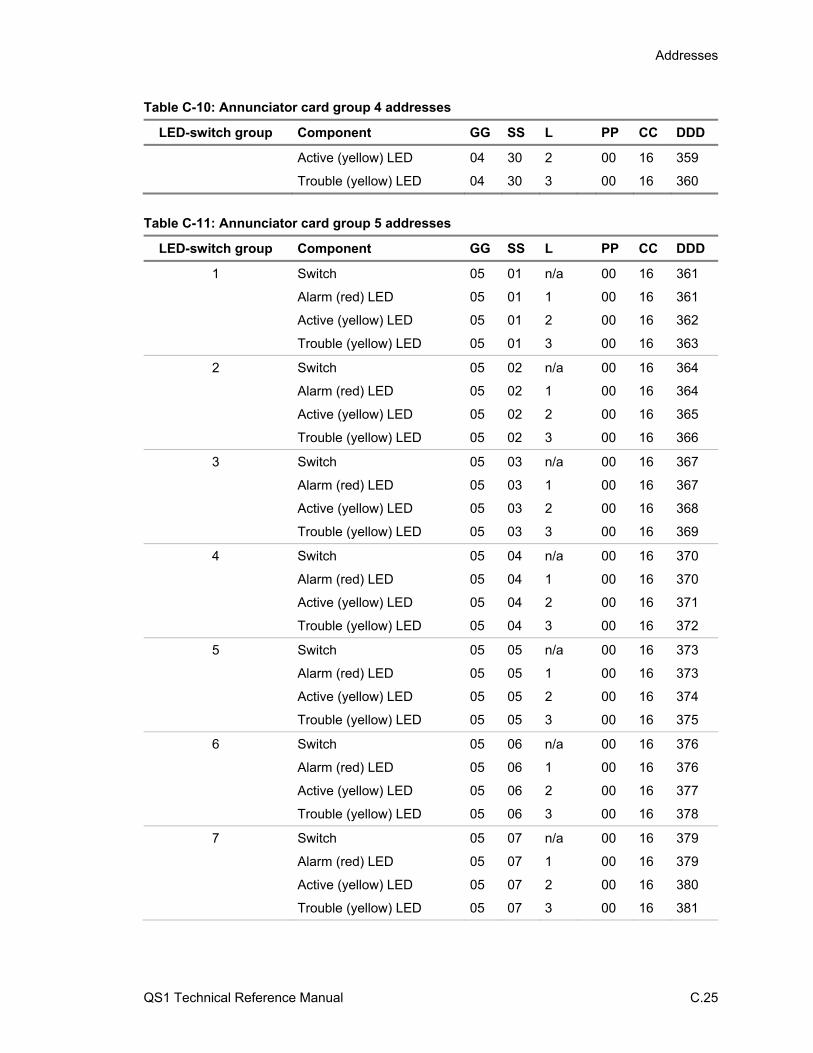
Addresses
QS1 Technical Reference Manual C.25
Table C-10: Annunciator card group 4 addresses
LED-switch group Component GG SS L PP CC DDD
Active (yellow) LED 04 30 2 00 16 359
Trouble (yellow) LED 04 30 3 00 16 360
Table C-11: Annunciator card group 5 addresses
LED-switch group Component GG SS L PP CC DDD
1 Switch 05 01 n/a 00 16 361
Alarm (red) LED 05 01 1 00 16 361
Active (yellow) LED 05 01 2 00 16 362
Trouble (yellow) LED 05 01 3 00 16 363
2 Switch 05 02 n/a 00 16 364
Alarm (red) LED 05 02 1 00 16 364
Active (yellow) LED 05 02 2 00 16 365
Trouble (yellow) LED 05 02 3 00 16 366
3 Switch 05 03 n/a 00 16 367
Alarm (red) LED 05 03 1 00 16 367
Active (yellow) LED 05 03 2 00 16 368
Trouble (yellow) LED 05 03 3 00 16 369
4 Switch 05 04 n/a 00 16 370
Alarm (red) LED 05 04 1 00 16 370
Active (yellow) LED 05 04 2 00 16 371
Trouble (yellow) LED 05 04 3 00 16 372
5 Switch 05 05 n/a 00 16 373
Alarm (red) LED 05 05 1 00 16 373
Active (yellow) LED 05 05 2 00 16 374
Trouble (yellow) LED 05 05 3 00 16 375
6 Switch 05 06 n/a 00 16 376
Alarm (red) LED 05 06 1 00 16 376
Active (yellow) LED 05 06 2 00 16 377
Trouble (yellow) LED 05 06 3 00 16 378
7 Switch 05 07 n/a 00 16 379
Alarm (red) LED 05 07 1 00 16 379
Active (yellow) LED 05 07 2 00 16 380
Trouble (yellow) LED 05 07 3 00 16 381

Addresses
C.26 QS1 Technical Reference Manual
Table C-11: Annunciator card group 5 addresses
LED-switch group Component GG SS L PP CC DDD
8 Switch 05 08 n/a 00 16 382
Alarm (red) LED 05 08 1 00 16 382
Active (yellow) LED 05 08 2 00 16 383
Trouble (yellow) LED 05 08 3 00 16 384
9 Switch 05 09 n/a 00 16 385
Alarm (red) LED 05 09 1 00 16 385
Active (yellow) LED 05 09 2 00 16 386
Trouble (yellow) LED 05 09 3 00 16 387
10 Switch 05 10 n/a 00 16 388
Alarm (red) LED 05 10 1 00 16 388
Active (yellow) LED 05 10 2 00 16 389
Trouble (yellow) LED 05 10 3 00 16 390
11 Switch 05 11 n/a 00 16 391
Alarm (red) LED 05 11 1 00 16 391
Active (yellow) LED 05 11 2 00 16 392
Trouble (yellow) LED 05 11 3 00 16 393
12 Switch 05 12 n/a 00 16 394
Alarm (red) LED 05 12 1 00 16 394
Active (yellow) LED 05 12 2 00 16 395
Trouble (yellow) LED 05 12 3 00 16 396
13 Switch 05 13 n/a 00 16 397
Alarm (red) LED 05 13 1 00 16 397
Active (yellow) LED 05 13 2 00 16 398
Trouble (yellow) LED 05 13 3 00 16 399
14 Switch 05 14 n/a 00 16 400
Alarm (red) LED 05 14 1 00 16 400
Active (yellow) LED 05 14 2 00 16 401
Trouble (yellow) LED 05 14 3 00 16 402
15 Switch 05 15 n/a 00 16 403
Alarm (red) LED 05 15 1 00 16 403
Active (yellow) LED 05 15 2 00 16 404
Trouble (yellow) LED 05 15 3 00 16 405
16 Switch 05 16 n/a 00 16 406
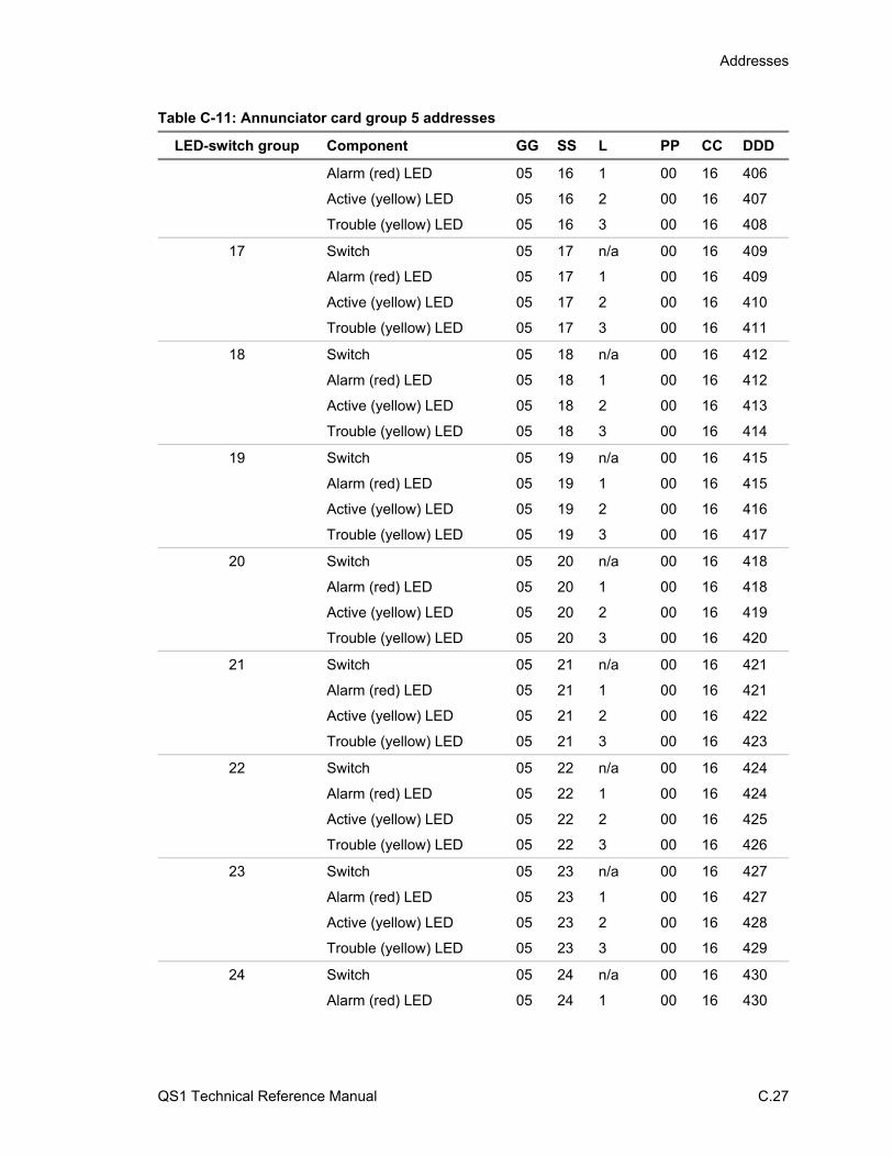
Addresses
QS1 Technical Reference Manual C.27
Table C-11: Annunciator card group 5 addresses
LED-switch group Component GG SS L PP CC DDD
Alarm (red) LED 05 16 1 00 16 406
Active (yellow) LED 05 16 2 00 16 407
Trouble (yellow) LED 05 16 3 00 16 408
17 Switch 05 17 n/a 00 16 409
Alarm (red) LED 05 17 1 00 16 409
Active (yellow) LED 05 17 2 00 16 410
Trouble (yellow) LED 05 17 3 00 16 411
18 Switch 05 18 n/a 00 16 412
Alarm (red) LED 05 18 1 00 16 412
Active (yellow) LED 05 18 2 00 16 413
Trouble (yellow) LED 05 18 3 00 16 414
19 Switch 05 19 n/a 00 16 415
Alarm (red) LED 05 19 1 00 16 415
Active (yellow) LED 05 19 2 00 16 416
Trouble (yellow) LED 05 19 3 00 16 417
20 Switch 05 20 n/a 00 16 418
Alarm (red) LED 05 20 1 00 16 418
Active (yellow) LED 05 20 2 00 16 419
Trouble (yellow) LED 05 20 3 00 16 420
21 Switch 05 21 n/a 00 16 421
Alarm (red) LED 05 21 1 00 16 421
Active (yellow) LED 05 21 2 00 16 422
Trouble (yellow) LED 05 21 3 00 16 423
22 Switch 05 22 n/a 00 16 424
Alarm (red) LED 05 22 1 00 16 424
Active (yellow) LED 05 22 2 00 16 425
Trouble (yellow) LED 05 22 3 00 16 426
23 Switch 05 23 n/a 00 16 427
Alarm (red) LED 05 23 1 00 16 427
Active (yellow) LED 05 23 2 00 16 428
Trouble (yellow) LED 05 23 3 00 16 429
24 Switch 05 24 n/a 00 16 430
Alarm (red) LED 05 24 1 00 16 430
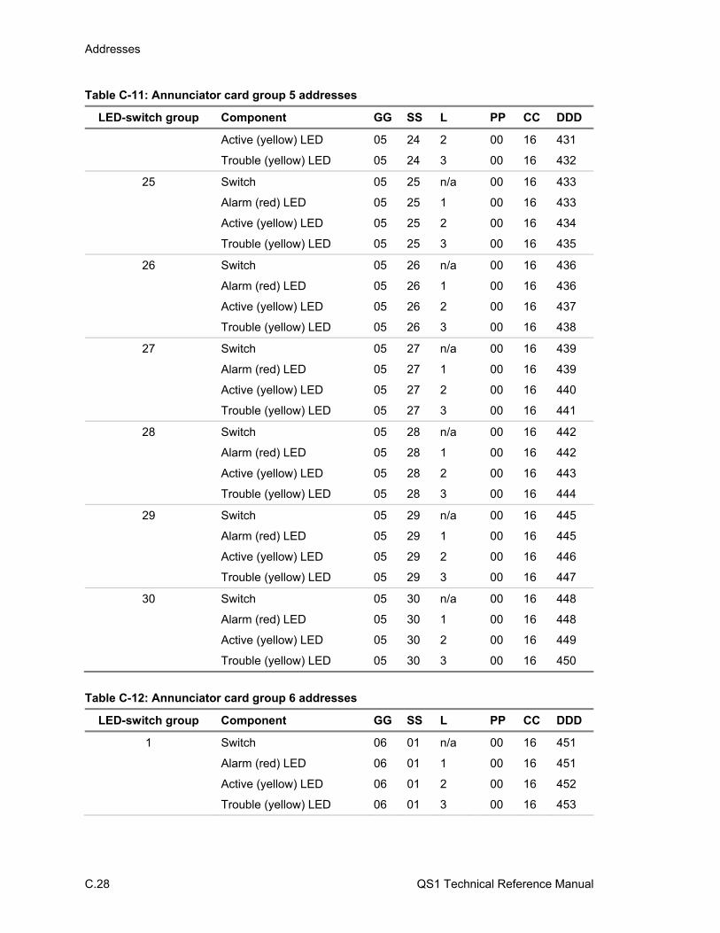
Addresses
C.28 QS1 Technical Reference Manual
Table C-11: Annunciator card group 5 addresses
LED-switch group Component GG SS L PP CC DDD
Active (yellow) LED 05 24 2 00 16 431
Trouble (yellow) LED 05 24 3 00 16 432
25 Switch 05 25 n/a 00 16 433
Alarm (red) LED 05 25 1 00 16 433
Active (yellow) LED 05 25 2 00 16 434
Trouble (yellow) LED 05 25 3 00 16 435
26 Switch 05 26 n/a 00 16 436
Alarm (red) LED 05 26 1 00 16 436
Active (yellow) LED 05 26 2 00 16 437
Trouble (yellow) LED 05 26 3 00 16 438
27 Switch 05 27 n/a 00 16 439
Alarm (red) LED 05 27 1 00 16 439
Active (yellow) LED 05 27 2 00 16 440
Trouble (yellow) LED 05 27 3 00 16 441
28 Switch 05 28 n/a 00 16 442
Alarm (red) LED 05 28 1 00 16 442
Active (yellow) LED 05 28 2 00 16 443
Trouble (yellow) LED 05 28 3 00 16 444
29 Switch 05 29 n/a 00 16 445
Alarm (red) LED 05 29 1 00 16 445
Active (yellow) LED 05 29 2 00 16 446
Trouble (yellow) LED 05 29 3 00 16 447
30 Switch 05 30 n/a 00 16 448
Alarm (red) LED 05 30 1 00 16 448
Active (yellow) LED 05 30 2 00 16 449
Trouble (yellow) LED 05 30 3 00 16 450
Table C-12: Annunciator card group 6 addresses
LED-switch group Component GG SS L PP CC DDD
1 Switch 06 01 n/a 00 16 451
Alarm (red) LED 06 01 1 00 16 451
Active (yellow) LED 06 01 2 00 16 452
Trouble (yellow) LED 06 01 3 00 16 453

Addresses
QS1 Technical Reference Manual C.29
Table C-12: Annunciator card group 6 addresses
LED-switch group Component GG SS L PP CC DDD
2 Switch 06 02 n/a 00 16 454
Alarm (red) LED 06 02 1 00 16 454
Active (yellow) LED 06 02 2 00 16 455
Trouble (yellow) LED 06 02 3 00 16 456
3 Switch 06 03 n/a 00 16 457
Alarm (red) LED 06 03 1 00 16 457
Active (yellow) LED 06 03 2 00 16 458
Trouble (yellow) LED 06 03 3 00 16 459
4 Switch 06 04 n/a 00 16 460
Alarm (red) LED 06 04 1 00 16 460
Active (yellow) LED 06 04 2 00 16 461
Trouble (yellow) LED 06 04 3 00 16 462
5 Switch 06 05 n/a 00 16 463
Alarm (red) LED 06 05 1 00 16 463
Active (yellow) LED 06 05 2 00 16 464
Trouble (yellow) LED 06 05 3 00 16 465
6 Switch 06 06 n/a 00 16 466
Alarm (red) LED 06 06 1 00 16 466
Active (yellow) LED 06 06 2 00 16 467
Trouble (yellow) LED 06 06 3 00 16 468
7 Switch 06 07 n/a 00 16 469
Alarm (red) LED 06 07 1 00 16 469
Active (yellow) LED 06 07 2 00 16 470
Trouble (yellow) LED 06 07 3 00 16 471
8 Switch 06 08 n/a 00 16 472
Alarm (red) LED 06 08 1 00 16 472
Active (yellow) LED 06 08 2 00 16 473
Trouble (yellow) LED 06 08 3 00 16 474
9 Switch 06 09 n/a 00 16 475
Alarm (red) LED 06 09 1 00 16 475
Active (yellow) LED 06 09 2 00 16 476
Trouble (yellow) LED 06 09 3 00 16 477
10 Switch 06 10 n/a 00 16 478
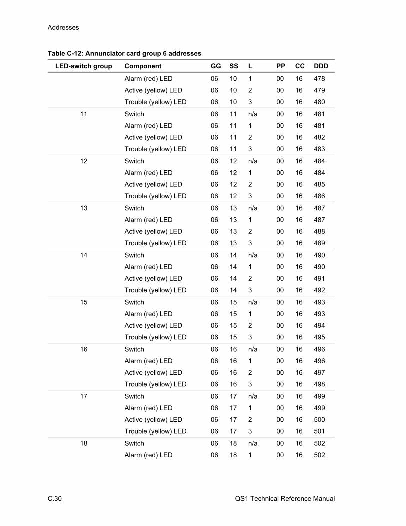
Addresses
C.30 QS1 Technical Reference Manual
Table C-12: Annunciator card group 6 addresses
LED-switch group Component GG SS L PP CC DDD
Alarm (red) LED 06 10 1 00 16 478
Active (yellow) LED 06 10 2 00 16 479
Trouble (yellow) LED 06 10 3 00 16 480
11 Switch 06 11 n/a 00 16 481
Alarm (red) LED 06 11 1 00 16 481
Active (yellow) LED 06 11 2 00 16 482
Trouble (yellow) LED 06 11 3 00 16 483
12 Switch 06 12 n/a 00 16 484
Alarm (red) LED 06 12 1 00 16 484
Active (yellow) LED 06 12 2 00 16 485
Trouble (yellow) LED 06 12 3 00 16 486
13 Switch 06 13 n/a 00 16 487
Alarm (red) LED 06 13 1 00 16 487
Active (yellow) LED 06 13 2 00 16 488
Trouble (yellow) LED 06 13 3 00 16 489
14 Switch 06 14 n/a 00 16 490
Alarm (red) LED 06 14 1 00 16 490
Active (yellow) LED 06 14 2 00 16 491
Trouble (yellow) LED 06 14 3 00 16 492
15 Switch 06 15 n/a 00 16 493
Alarm (red) LED 06 15 1 00 16 493
Active (yellow) LED 06 15 2 00 16 494
Trouble (yellow) LED 06 15 3 00 16 495
16 Switch 06 16 n/a 00 16 496
Alarm (red) LED 06 16 1 00 16 496
Active (yellow) LED 06 16 2 00 16 497
Trouble (yellow) LED 06 16 3 00 16 498
17 Switch 06 17 n/a 00 16 499
Alarm (red) LED 06 17 1 00 16 499
Active (yellow) LED 06 17 2 00 16 500
Trouble (yellow) LED 06 17 3 00 16 501
18 Switch 06 18 n/a 00 16 502
Alarm (red) LED 06 18 1 00 16 502

Addresses
QS1 Technical Reference Manual C.31
Table C-12: Annunciator card group 6 addresses
LED-switch group Component GG SS L PP CC DDD
Active (yellow) LED 06 18 2 00 16 503
Trouble (yellow) LED 06 18 3 00 16 504
19 Switch 06 19 n/a 00 16 505
Alarm (red) LED 06 19 1 00 16 505
Active (yellow) LED 06 19 2 00 16 506
Trouble (yellow) LED 06 19 3 00 16 507
20 Switch 06 20 n/a 00 16 508
Alarm (red) LED 06 20 1 00 16 508
Active (yellow) LED 06 20 2 00 16 509
Trouble (yellow) LED 06 20 3 00 16 510
21 Switch 06 21 n/a 00 16 511
Alarm (red) LED 06 21 1 00 16 511
Active (yellow) LED 06 21 2 00 16 512
Trouble (yellow) LED 06 21 3 00 16 513
22 Switch 06 22 n/a 00 16 514
Alarm (red) LED 06 22 1 00 16 514
Active (yellow) LED 06 22 2 00 16 515
Trouble (yellow) LED 06 22 3 00 16 516
23 Switch 06 23 n/a 00 16 517
Alarm (red) LED 06 23 1 00 16 517
Active (yellow) LED 06 23 2 00 16 518
Trouble (yellow) LED 06 23 3 00 16 519
24 Switch 06 24 n/a 00 16 520
Alarm (red) LED 06 24 1 00 16 520
Active (yellow) LED 06 24 2 00 16 521
Trouble (yellow) LED 06 24 3 00 16 522
25 Switch 06 25 n/a 00 16 523
Alarm (red) LED 06 25 1 00 16 523
Active (yellow) LED 06 25 2 00 16 524
Trouble (yellow) LED 06 25 3 00 16 525
26 Switch 06 26 n/a 00 16 526
Alarm (red) LED 06 26 1 00 16 526
Active (yellow) LED 06 26 2 00 16 527
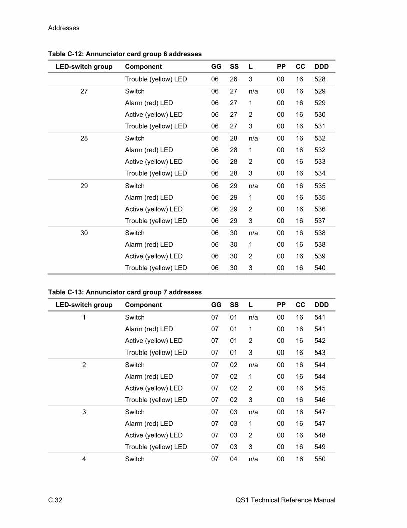
Addresses
C.32 QS1 Technical Reference Manual
Table C-12: Annunciator card group 6 addresses
LED-switch group Component GG SS L PP CC DDD
Trouble (yellow) LED 06 26 3 00 16 528
27 Switch 06 27 n/a 00 16 529
Alarm (red) LED 06 27 1 00 16 529
Active (yellow) LED 06 27 2 00 16 530
Trouble (yellow) LED 06 27 3 00 16 531
28 Switch 06 28 n/a 00 16 532
Alarm (red) LED 06 28 1 00 16 532
Active (yellow) LED 06 28 2 00 16 533
Trouble (yellow) LED 06 28 3 00 16 534
29 Switch 06 29 n/a 00 16 535
Alarm (red) LED 06 29 1 00 16 535
Active (yellow) LED 06 29 2 00 16 536
Trouble (yellow) LED 06 29 3 00 16 537
30 Switch 06 30 n/a 00 16 538
Alarm (red) LED 06 30 1 00 16 538
Active (yellow) LED 06 30 2 00 16 539
Trouble (yellow) LED 06 30 3 00 16 540
Table C-13: Annunciator card group 7 addresses
LED-switch group Component GG SS L PP CC DDD
1 Switch 07 01 n/a 00 16 541
Alarm (red) LED 07 01 1 00 16 541
Active (yellow) LED 07 01 2 00 16 542
Trouble (yellow) LED 07 01 3 00 16 543
2 Switch 07 02 n/a 00 16 544
Alarm (red) LED 07 02 1 00 16 544
Active (yellow) LED 07 02 2 00 16 545
Trouble (yellow) LED 07 02 3 00 16 546
3 Switch 07 03 n/a 00 16 547
Alarm (red) LED 07 03 1 00 16 547
Active (yellow) LED 07 03 2 00 16 548
Trouble (yellow) LED 07 03 3 00 16 549
4 Switch 07 04 n/a 00 16 550
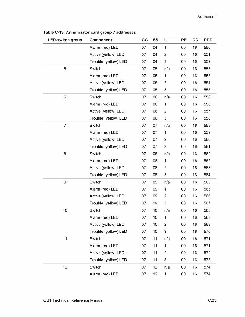
Addresses
QS1 Technical Reference Manual C.33
Table C-13: Annunciator card group 7 addresses
LED-switch group Component GG SS L PP CC DDD
Alarm (red) LED 07 04 1 00 16 550
Active (yellow) LED 07 04 2 00 16 551
Trouble (yellow) LED 07 04 3 00 16 552
5 Switch 07 05 n/a 00 16 553
Alarm (red) LED 07 05 1 00 16 553
Active (yellow) LED 07 05 2 00 16 554
Trouble (yellow) LED 07 05 3 00 16 555
6 Switch 07 06 n/a 00 16 556
Alarm (red) LED 07 06 1 00 16 556
Active (yellow) LED 07 06 2 00 16 557
Trouble (yellow) LED 07 06 3 00 16 558
7 Switch 07 07 n/a 00 16 559
Alarm (red) LED 07 07 1 00 16 559
Active (yellow) LED 07 07 2 00 16 560
Trouble (yellow) LED 07 07 3 00 16 561
8 Switch 07 08 n/a 00 16 562
Alarm (red) LED 07 08 1 00 16 562
Active (yellow) LED 07 08 2 00 16 563
Trouble (yellow) LED 07 08 3 00 16 564
9 Switch 07 09 n/a 00 16 565
Alarm (red) LED 07 09 1 00 16 565
Active (yellow) LED 07 09 2 00 16 566
Trouble (yellow) LED 07 09 3 00 16 567
10 Switch 07 10 n/a 00 16 568
Alarm (red) LED 07 10 1 00 16 568
Active (yellow) LED 07 10 2 00 16 569
Trouble (yellow) LED 07 10 3 00 16 570
11 Switch 07 11 n/a 00 16 571
Alarm (red) LED 07 11 1 00 16 571
Active (yellow) LED 07 11 2 00 16 572
Trouble (yellow) LED 07 11 3 00 16 573
12 Switch 07 12 n/a 00 16 574
Alarm (red) LED 07 12 1 00 16 574

Addresses
C.34 QS1 Technical Reference Manual
Table C-13: Annunciator card group 7 addresses
LED-switch group Component GG SS L PP CC DDD
Active (yellow) LED 07 12 2 00 16 575
Trouble (yellow) LED 07 12 3 00 16 576
13 Switch 07 13 n/a 00 16 577
Alarm (red) LED 07 13 1 00 16 577
Active (yellow) LED 07 13 2 00 16 578
Trouble (yellow) LED 07 13 3 00 16 579
14 Switch 07 14 n/a 00 16 580
Alarm (red) LED 07 14 1 00 16 580
Active (yellow) LED 07 14 2 00 16 581
Trouble (yellow) LED 07 14 3 00 16 582
15 Switch 07 15 n/a 00 16 583
Alarm (red) LED 07 15 1 00 16 583
Active (yellow) LED 07 15 2 00 16 584
Trouble (yellow) LED 07 15 3 00 16 585
16 Switch 07 16 n/a 00 16 586
Alarm (red) LED 07 16 1 00 16 586
Active (yellow) LED 07 16 2 00 16 587
Trouble (yellow) LED 07 16 3 00 16 588
17 Switch 07 17 n/a 00 16 589
Alarm (red) LED 07 17 1 00 16 589
Active (yellow) LED 07 17 2 00 16 590
Trouble (yellow) LED 07 17 3 00 16 591
18 Switch 07 18 n/a 00 16 592
Alarm (red) LED 07 18 1 00 16 592
Active (yellow) LED 07 18 2 00 16 593
Trouble (yellow) LED 07 18 3 00 16 594
19 Switch 07 19 n/a 00 16 595
Alarm (red) LED 07 19 1 00 16 595
Active (yellow) LED 07 19 2 00 16 596
Trouble (yellow) LED 07 19 3 00 16 597
20 Switch 07 20 n/a 00 16 598
Alarm (red) LED 07 20 1 00 16 598
Active (yellow) LED 07 20 2 00 16 599
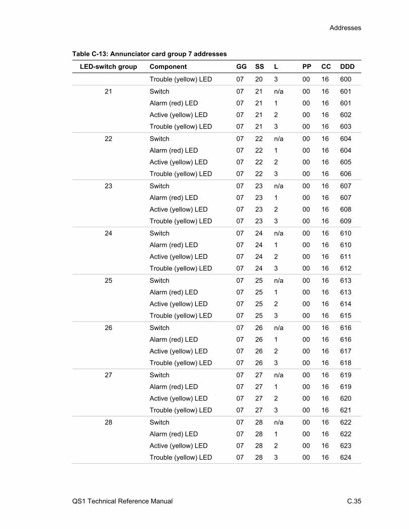
Addresses
QS1 Technical Reference Manual C.35
Table C-13: Annunciator card group 7 addresses
LED-switch group Component GG SS L PP CC DDD
Trouble (yellow) LED 07 20 3 00 16 600
21 Switch 07 21 n/a 00 16 601
Alarm (red) LED 07 21 1 00 16 601
Active (yellow) LED 07 21 2 00 16 602
Trouble (yellow) LED 07 21 3 00 16 603
22 Switch 07 22 n/a 00 16 604
Alarm (red) LED 07 22 1 00 16 604
Active (yellow) LED 07 22 2 00 16 605
Trouble (yellow) LED 07 22 3 00 16 606
23 Switch 07 23 n/a 00 16 607
Alarm (red) LED 07 23 1 00 16 607
Active (yellow) LED 07 23 2 00 16 608
Trouble (yellow) LED 07 23 3 00 16 609
24 Switch 07 24 n/a 00 16 610
Alarm (red) LED 07 24 1 00 16 610
Active (yellow) LED 07 24 2 00 16 611
Trouble (yellow) LED 07 24 3 00 16 612
25 Switch 07 25 n/a 00 16 613
Alarm (red) LED 07 25 1 00 16 613
Active (yellow) LED 07 25 2 00 16 614
Trouble (yellow) LED 07 25 3 00 16 615
26 Switch 07 26 n/a 00 16 616
Alarm (red) LED 07 26 1 00 16 616
Active (yellow) LED 07 26 2 00 16 617
Trouble (yellow) LED 07 26 3 00 16 618
27 Switch 07 27 n/a 00 16 619
Alarm (red) LED 07 27 1 00 16 619
Active (yellow) LED 07 27 2 00 16 620
Trouble (yellow) LED 07 27 3 00 16 621
28 Switch 07 28 n/a 00 16 622
Alarm (red) LED 07 28 1 00 16 622
Active (yellow) LED 07 28 2 00 16 623
Trouble (yellow) LED 07 28 3 00 16 624
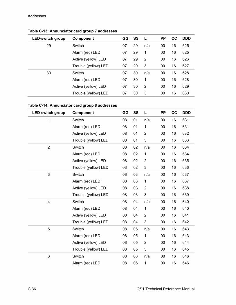
Addresses
C.36 QS1 Technical Reference Manual
Table C-13: Annunciator card group 7 addresses
LED-switch group Component GG SS L PP CC DDD
29 Switch 07 29 n/a 00 16 625
Alarm (red) LED 07 29 1 00 16 625
Active (yellow) LED 07 29 2 00 16 626
Trouble (yellow) LED 07 29 3 00 16 627
30 Switch 07 30 n/a 00 16 628
Alarm (red) LED 07 30 1 00 16 628
Active (yellow) LED 07 30 2 00 16 629
Trouble (yellow) LED 07 30 3 00 16 630
Table C-14: Annunciator card group 8 addresses
LED-switch group Component GG SS L PP CC DDD
1 Switch 08 01 n/a 00 16 631
Alarm (red) LED 08 01 1 00 16 631
Active (yellow) LED 08 01 2 00 16 632
Trouble (yellow) LED 08 01 3 00 16 633
2 Switch 08 02 n/a 00 16 634
Alarm (red) LED 08 02 1 00 16 634
Active (yellow) LED 08 02 2 00 16 635
Trouble (yellow) LED 08 02 3 00 16 636
3 Switch 08 03 n/a 00 16 637
Alarm (red) LED 08 03 1 00 16 637
Active (yellow) LED 08 03 2 00 16 638
Trouble (yellow) LED 08 03 3 00 16 639
4 Switch 08 04 n/a 00 16 640
Alarm (red) LED 08 04 1 00 16 640
Active (yellow) LED 08 04 2 00 16 641
Trouble (yellow) LED 08 04 3 00 16 642
5 Switch 08 05 n/a 00 16 643
Alarm (red) LED 08 05 1 00 16 643
Active (yellow) LED 08 05 2 00 16 644
Trouble (yellow) LED 08 05 3 00 16 645
6 Switch 08 06 n/a 00 16 646
Alarm (red) LED 08 06 1 00 16 646
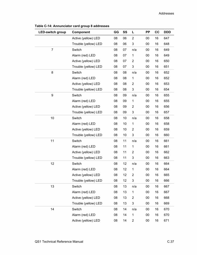
Addresses
QS1 Technical Reference Manual C.37
Table C-14: Annunciator card group 8 addresses
LED-switch group Component GG SS L PP CC DDD
Active (yellow) LED 08 06 2 00 16 647
Trouble (yellow) LED 08 06 3 00 16 648
7 Switch 08 07 n/a 00 16 649
Alarm (red) LED 08 07 1 00 16 649
Active (yellow) LED 08 07 2 00 16 650
Trouble (yellow) LED 08 07 3 00 16 651
8 Switch 08 08 n/a 00 16 652
Alarm (red) LED 08 08 1 00 16 652
Active (yellow) LED 08 08 2 00 16 653
Trouble (yellow) LED 08 08 3 00 16 654
9 Switch 08 09 n/a 00 16 655
Alarm (red) LED 08 09 1 00 16 655
Active (yellow) LED 08 09 2 00 16 656
Trouble (yellow) LED 08 09 3 00 16 657
10 Switch 08 10 n/a 00 16 658
Alarm (red) LED 08 10 1 00 16 658
Active (yellow) LED 08 10 2 00 16 659
Trouble (yellow) LED 08 10 3 00 16 660
11 Switch 08 11 n/a 00 16 661
Alarm (red) LED 08 11 1 00 16 661
Active (yellow) LED 08 11 2 00 16 662
Trouble (yellow) LED 08 11 3 00 16 663
12 Switch 08 12 n/a 00 16 664
Alarm (red) LED 08 12 1 00 16 664
Active (yellow) LED 08 12 2 00 16 665
Trouble (yellow) LED 08 12 3 00 16 666
13 Switch 08 13 n/a 00 16 667
Alarm (red) LED 08 13 1 00 16 667
Active (yellow) LED 08 13 2 00 16 668
Trouble (yellow) LED 08 13 3 00 16 669
14 Switch 08 14 n/a 00 16 670
Alarm (red) LED 08 14 1 00 16 670
Active (yellow) LED 08 14 2 00 16 671
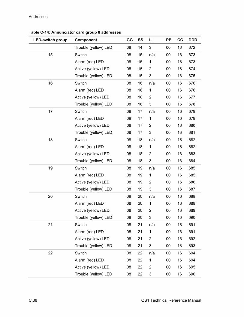
Addresses
C.38 QS1 Technical Reference Manual
Table C-14: Annunciator card group 8 addresses
LED-switch group Component GG SS L PP CC DDD
Trouble (yellow) LED 08 14 3 00 16 672
15 Switch 08 15 n/a 00 16 673
Alarm (red) LED 08 15 1 00 16 673
Active (yellow) LED 08 15 2 00 16 674
Trouble (yellow) LED 08 15 3 00 16 675
16 Switch 08 16 n/a 00 16 676
Alarm (red) LED 08 16 1 00 16 676
Active (yellow) LED 08 16 2 00 16 677
Trouble (yellow) LED 08 16 3 00 16 678
17 Switch 08 17 n/a 00 16 679
Alarm (red) LED 08 17 1 00 16 679
Active (yellow) LED 08 17 2 00 16 680
Trouble (yellow) LED 08 17 3 00 16 681
18 Switch 08 18 n/a 00 16 682
Alarm (red) LED 08 18 1 00 16 682
Active (yellow) LED 08 18 2 00 16 683
Trouble (yellow) LED 08 18 3 00 16 684
19 Switch 08 19 n/a 00 16 685
Alarm (red) LED 08 19 1 00 16 685
Active (yellow) LED 08 19 2 00 16 686
Trouble (yellow) LED 08 19 3 00 16 687
20 Switch 08 20 n/a 00 16 688
Alarm (red) LED 08 20 1 00 16 688
Active (yellow) LED 08 20 2 00 16 689
Trouble (yellow) LED 08 20 3 00 16 690
21 Switch 08 21 n/a 00 16 691
Alarm (red) LED 08 21 1 00 16 691
Active (yellow) LED 08 21 2 00 16 692
Trouble (yellow) LED 08 21 3 00 16 693
22 Switch 08 22 n/a 00 16 694
Alarm (red) LED 08 22 1 00 16 694
Active (yellow) LED 08 22 2 00 16 695
Trouble (yellow) LED 08 22 3 00 16 696
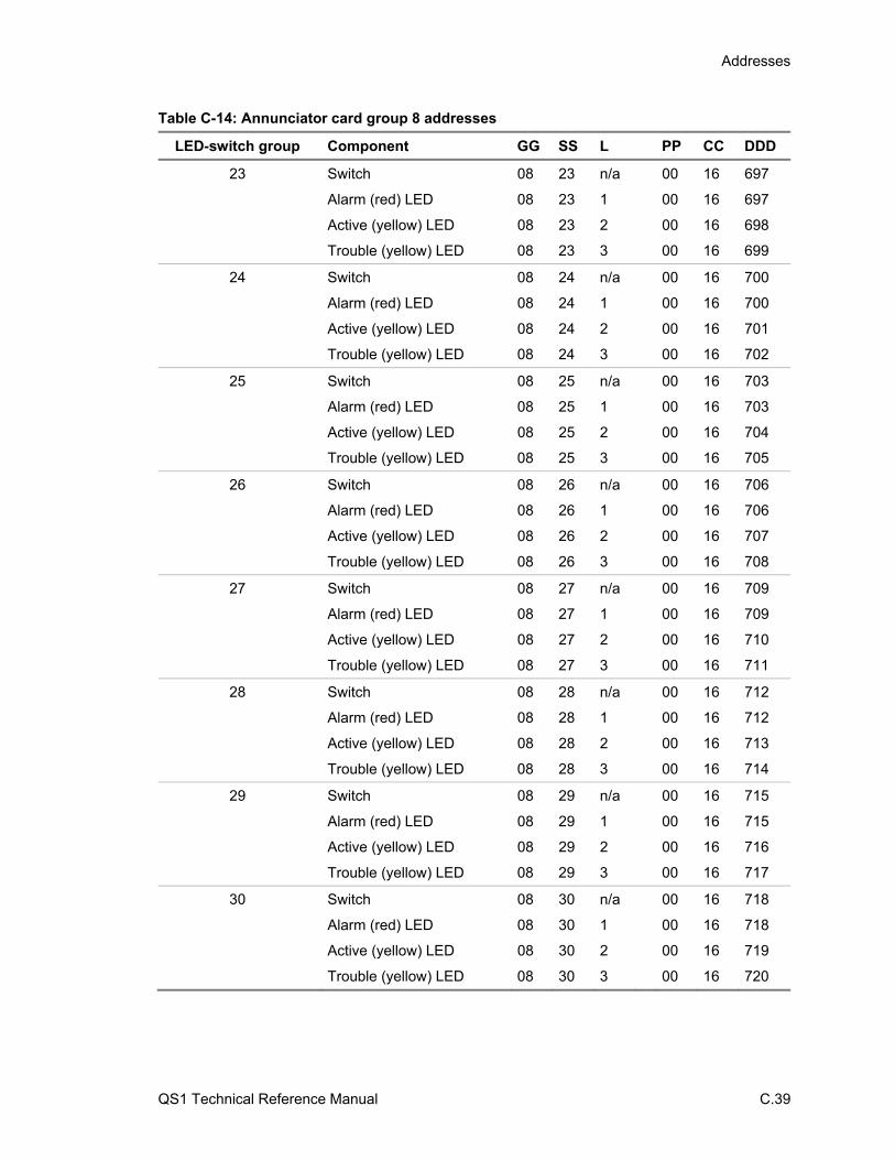
Addresses
QS1 Technical Reference Manual C.39
Table C-14: Annunciator card group 8 addresses
LED-switch group Component GG SS L PP CC DDD
23 Switch 08 23 n/a 00 16 697
Alarm (red) LED 08 23 1 00 16 697
Active (yellow) LED 08 23 2 00 16 698
Trouble (yellow) LED 08 23 3 00 16 699
24 Switch 08 24 n/a 00 16 700
Alarm (red) LED 08 24 1 00 16 700
Active (yellow) LED 08 24 2 00 16 701
Trouble (yellow) LED 08 24 3 00 16 702
25 Switch 08 25 n/a 00 16 703
Alarm (red) LED 08 25 1 00 16 703
Active (yellow) LED 08 25 2 00 16 704
Trouble (yellow) LED 08 25 3 00 16 705
26 Switch 08 26 n/a 00 16 706
Alarm (red) LED 08 26 1 00 16 706
Active (yellow) LED 08 26 2 00 16 707
Trouble (yellow) LED 08 26 3 00 16 708
27 Switch 08 27 n/a 00 16 709
Alarm (red) LED 08 27 1 00 16 709
Active (yellow) LED 08 27 2 00 16 710
Trouble (yellow) LED 08 27 3 00 16 711
28 Switch 08 28 n/a 00 16 712
Alarm (red) LED 08 28 1 00 16 712
Active (yellow) LED 08 28 2 00 16 713
Trouble (yellow) LED 08 28 3 00 16 714
29 Switch 08 29 n/a 00 16 715
Alarm (red) LED 08 29 1 00 16 715
Active (yellow) LED 08 29 2 00 16 716
Trouble (yellow) LED 08 29 3 00 16 717
30 Switch 08 30 n/a 00 16 718
Alarm (red) LED 08 30 1 00 16 718
Active (yellow) LED 08 30 2 00 16 719
Trouble (yellow) LED 08 30 3 00 16 720

Addresses
C.40 QS1 Technical Reference Manual
Table C-15: Annunciator card group 9 addresses
LED-switch group Component GG SS L PP CC DDD
1 Switch 09 01 n/a 00 16 721
Alarm (red) LED 09 01 1 00 16 721
Active (yellow) LED 09 01 2 00 16 722
Trouble (yellow) LED 09 01 3 00 16 723
2 Switch 09 02 n/a 00 16 724
Alarm (red) LED 09 02 1 00 16 724
Active (yellow) LED 09 02 2 00 16 725
Trouble (yellow) LED 09 02 3 00 16 726
3 Switch 09 03 n/a 00 16 727
Alarm (red) LED 09 03 1 00 16 727
Active (yellow) LED 09 03 2 00 16 728
Trouble (yellow) LED 09 03 3 00 16 729
4 Switch 09 04 n/a 00 16 730
Alarm (red) LED 09 04 1 00 16 730
Active (yellow) LED 09 04 2 00 16 731
Trouble (yellow) LED 09 04 3 00 16 732
5 Switch 09 05 n/a 00 16 733
Alarm (red) LED 09 05 1 00 16 733
Active (yellow) LED 09 05 2 00 16 734
Trouble (yellow) LED 09 05 3 00 16 735
6 Switch 09 06 n/a 00 16 736
Alarm (red) LED 09 06 1 00 16 736
Active (yellow) LED 09 06 2 00 16 737
Trouble (yellow) LED 09 06 3 00 16 738
7 Switch 09 07 n/a 00 16 739
Alarm (red) LED 09 07 1 00 16 739
Active (yellow) LED 09 07 2 00 16 740
Trouble (yellow) LED 09 07 3 00 16 741
8 Switch 09 08 n/a 00 16 742
Alarm (red) LED 09 08 1 00 16 742
Active (yellow) LED 09 08 2 00 16 743
Trouble (yellow) LED 09 08 3 00 16 744
9 Switch 09 09 n/a 00 16 745
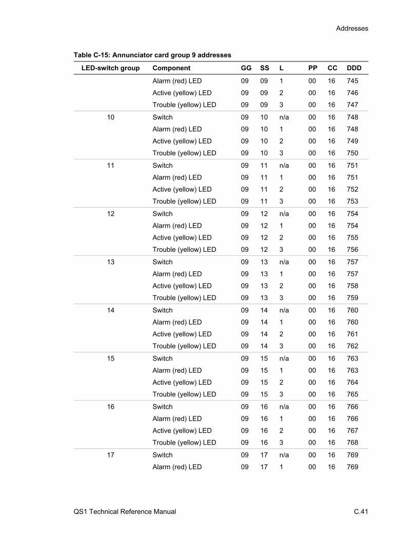
Addresses
QS1 Technical Reference Manual C.41
Table C-15: Annunciator card group 9 addresses
LED-switch group Component GG SS L PP CC DDD
Alarm (red) LED 09 09 1 00 16 745
Active (yellow) LED 09 09 2 00 16 746
Trouble (yellow) LED 09 09 3 00 16 747
10 Switch 09 10 n/a 00 16 748
Alarm (red) LED 09 10 1 00 16 748
Active (yellow) LED 09 10 2 00 16 749
Trouble (yellow) LED 09 10 3 00 16 750
11 Switch 09 11 n/a 00 16 751
Alarm (red) LED 09 11 1 00 16 751
Active (yellow) LED 09 11 2 00 16 752
Trouble (yellow) LED 09 11 3 00 16 753
12 Switch 09 12 n/a 00 16 754
Alarm (red) LED 09 12 1 00 16 754
Active (yellow) LED 09 12 2 00 16 755
Trouble (yellow) LED 09 12 3 00 16 756
13 Switch 09 13 n/a 00 16 757
Alarm (red) LED 09 13 1 00 16 757
Active (yellow) LED 09 13 2 00 16 758
Trouble (yellow) LED 09 13 3 00 16 759
14 Switch 09 14 n/a 00 16 760
Alarm (red) LED 09 14 1 00 16 760
Active (yellow) LED 09 14 2 00 16 761
Trouble (yellow) LED 09 14 3 00 16 762
15 Switch 09 15 n/a 00 16 763
Alarm (red) LED 09 15 1 00 16 763
Active (yellow) LED 09 15 2 00 16 764
Trouble (yellow) LED 09 15 3 00 16 765
16 Switch 09 16 n/a 00 16 766
Alarm (red) LED 09 16 1 00 16 766
Active (yellow) LED 09 16 2 00 16 767
Trouble (yellow) LED 09 16 3 00 16 768
17 Switch 09 17 n/a 00 16 769
Alarm (red) LED 09 17 1 00 16 769

Addresses
C.42 QS1 Technical Reference Manual
Table C-15: Annunciator card group 9 addresses
LED-switch group Component GG SS L PP CC DDD
Active (yellow) LED 09 17 2 00 16 770
Trouble (yellow) LED 09 17 3 00 16 771
18 Switch 09 18 n/a 00 16 772
Alarm (red) LED 09 18 1 00 16 772
Active (yellow) LED 09 18 2 00 16 773
Trouble (yellow) LED 09 18 3 00 16 774
19 Switch 09 19 n/a 00 16 775
Alarm (red) LED 09 19 1 00 16 775
Active (yellow) LED 09 19 2 00 16 776
Trouble (yellow) LED 09 19 3 00 16 777
20 Switch 09 20 n/a 00 16 778
Alarm (red) LED 09 20 1 00 16 778
Active (yellow) LED 09 20 2 00 16 779
Trouble (yellow) LED 09 20 3 00 16 780
21 Switch 09 21 n/a 00 16 781
Alarm (red) LED 09 21 1 00 16 781
Active (yellow) LED 09 21 2 00 16 782
Trouble (yellow) LED 09 21 3 00 16 783
22 Switch 09 22 n/a 00 16 784
Alarm (red) LED 09 22 1 00 16 784
Active (yellow) LED 09 22 2 00 16 785
Trouble (yellow) LED 09 22 3 00 16 786
23 Switch 09 23 n/a 00 16 787
Alarm (red) LED 09 23 1 00 16 787
Active (yellow) LED 09 23 2 00 16 788
Trouble (yellow) LED 09 23 3 00 16 789
24 Switch 09 24 n/a 00 16 790
Alarm (red) LED 09 24 1 00 16 790
Active (yellow) LED 09 24 2 00 16 791
Trouble (yellow) LED 09 24 3 00 16 792
25 Switch 09 25 n/a 00 16 793
Alarm (red) LED 09 25 1 00 16 793
Active (yellow) LED 09 25 2 00 16 794
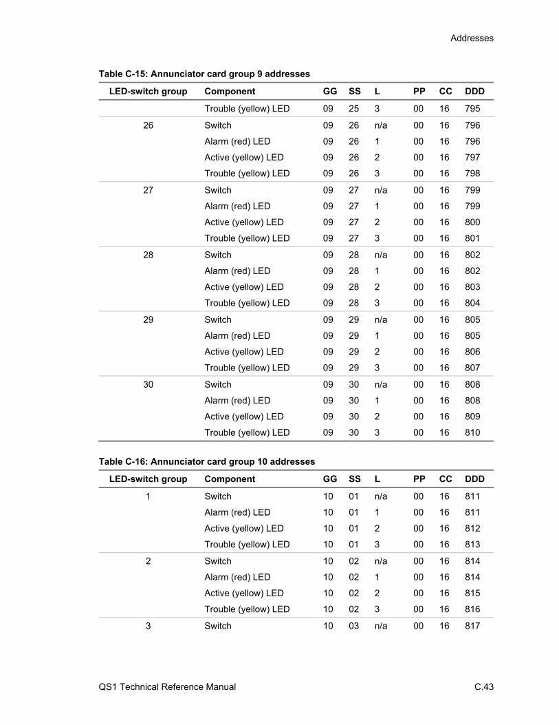
Addresses
QS1 Technical Reference Manual C.43
Table C-15: Annunciator card group 9 addresses
LED-switch group Component GG SS L PP CC DDD
Trouble (yellow) LED 09 25 3 00 16 795
26 Switch 09 26 n/a 00 16 796
Alarm (red) LED 09 26 1 00 16 796
Active (yellow) LED 09 26 2 00 16 797
Trouble (yellow) LED 09 26 3 00 16 798
27 Switch 09 27 n/a 00 16 799
Alarm (red) LED 09 27 1 00 16 799
Active (yellow) LED 09 27 2 00 16 800
Trouble (yellow) LED 09 27 3 00 16 801
28 Switch 09 28 n/a 00 16 802
Alarm (red) LED 09 28 1 00 16 802
Active (yellow) LED 09 28 2 00 16 803
Trouble (yellow) LED 09 28 3 00 16 804
29 Switch 09 29 n/a 00 16 805
Alarm (red) LED 09 29 1 00 16 805
Active (yellow) LED 09 29 2 00 16 806
Trouble (yellow) LED 09 29 3 00 16 807
30 Switch 09 30 n/a 00 16 808
Alarm (red) LED 09 30 1 00 16 808
Active (yellow) LED 09 30 2 00 16 809
Trouble (yellow) LED 09 30 3 00 16 810
Table C-16: Annunciator card group 10 addresses
LED-switch group Component GG SS L PP CC DDD
1 Switch 10 01 n/a 00 16 811
Alarm (red) LED 10 01 1 00 16 811
Active (yellow) LED 10 01 2 00 16 812
Trouble (yellow) LED 10 01 3 00 16 813
2 Switch 10 02 n/a 00 16 814
Alarm (red) LED 10 02 1 00 16 814
Active (yellow) LED 10 02 2 00 16 815
Trouble (yellow) LED 10 02 3 00 16 816
3 Switch 10 03 n/a 00 16 817
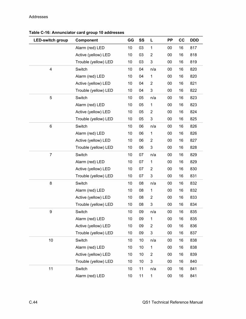
Addresses
C.44 QS1 Technical Reference Manual
Table C-16: Annunciator card group 10 addresses
LED-switch group Component GG SS L PP CC DDD
Alarm (red) LED 10 03 1 00 16 817
Active (yellow) LED 10 03 2 00 16 818
Trouble (yellow) LED 10 03 3 00 16 819
4 Switch 10 04 n/a 00 16 820
Alarm (red) LED 10 04 1 00 16 820
Active (yellow) LED 10 04 2 00 16 821
Trouble (yellow) LED 10 04 3 00 16 822
5 Switch 10 05 n/a 00 16 823
Alarm (red) LED 10 05 1 00 16 823
Active (yellow) LED 10 05 2 00 16 824
Trouble (yellow) LED 10 05 3 00 16 825
6 Switch 10 06 n/a 00 16 826
Alarm (red) LED 10 06 1 00 16 826
Active (yellow) LED 10 06 2 00 16 827
Trouble (yellow) LED 10 06 3 00 16 828
7 Switch 10 07 n/a 00 16 829
Alarm (red) LED 10 07 1 00 16 829
Active (yellow) LED 10 07 2 00 16 830
Trouble (yellow) LED 10 07 3 00 16 831
8 Switch 10 08 n/a 00 16 832
Alarm (red) LED 10 08 1 00 16 832
Active (yellow) LED 10 08 2 00 16 833
Trouble (yellow) LED 10 08 3 00 16 834
9 Switch 10 09 n/a 00 16 835
Alarm (red) LED 10 09 1 00 16 835
Active (yellow) LED 10 09 2 00 16 836
Trouble (yellow) LED 10 09 3 00 16 837
10 Switch 10 10 n/a 00 16 838
Alarm (red) LED 10 10 1 00 16 838
Active (yellow) LED 10 10 2 00 16 839
Trouble (yellow) LED 10 10 3 00 16 840
11 Switch 10 11 n/a 00 16 841
Alarm (red) LED 10 11 1 00 16 841
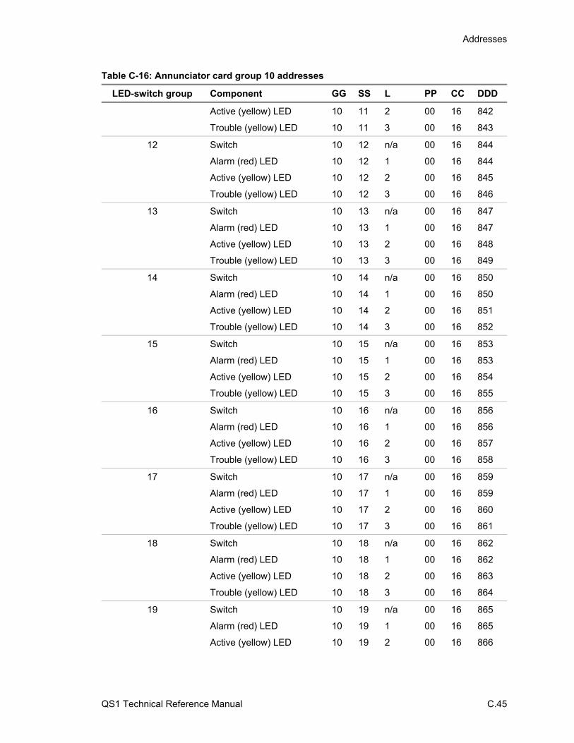
Addresses
QS1 Technical Reference Manual C.45
Table C-16: Annunciator card group 10 addresses
LED-switch group Component GG SS L PP CC DDD
Active (yellow) LED 10 11 2 00 16 842
Trouble (yellow) LED 10 11 3 00 16 843
12 Switch 10 12 n/a 00 16 844
Alarm (red) LED 10 12 1 00 16 844
Active (yellow) LED 10 12 2 00 16 845
Trouble (yellow) LED 10 12 3 00 16 846
13 Switch 10 13 n/a 00 16 847
Alarm (red) LED 10 13 1 00 16 847
Active (yellow) LED 10 13 2 00 16 848
Trouble (yellow) LED 10 13 3 00 16 849
14 Switch 10 14 n/a 00 16 850
Alarm (red) LED 10 14 1 00 16 850
Active (yellow) LED 10 14 2 00 16 851
Trouble (yellow) LED 10 14 3 00 16 852
15 Switch 10 15 n/a 00 16 853
Alarm (red) LED 10 15 1 00 16 853
Active (yellow) LED 10 15 2 00 16 854
Trouble (yellow) LED 10 15 3 00 16 855
16 Switch 10 16 n/a 00 16 856
Alarm (red) LED 10 16 1 00 16 856
Active (yellow) LED 10 16 2 00 16 857
Trouble (yellow) LED 10 16 3 00 16 858
17 Switch 10 17 n/a 00 16 859
Alarm (red) LED 10 17 1 00 16 859
Active (yellow) LED 10 17 2 00 16 860
Trouble (yellow) LED 10 17 3 00 16 861
18 Switch 10 18 n/a 00 16 862
Alarm (red) LED 10 18 1 00 16 862
Active (yellow) LED 10 18 2 00 16 863
Trouble (yellow) LED 10 18 3 00 16 864
19 Switch 10 19 n/a 00 16 865
Alarm (red) LED 10 19 1 00 16 865
Active (yellow) LED 10 19 2 00 16 866

Addresses
C.46 QS1 Technical Reference Manual
Table C-16: Annunciator card group 10 addresses
LED-switch group Component GG SS L PP CC DDD
Trouble (yellow) LED 10 19 3 00 16 867
20 Switch 10 20 n/a 00 16 868
Alarm (red) LED 10 20 1 00 16 868
Active (yellow) LED 10 20 2 00 16 869
Trouble (yellow) LED 10 20 3 00 16 870
21 Switch 10 21 n/a 00 16 871
Alarm (red) LED 10 21 1 00 16 871
Active (yellow) LED 10 21 2 00 16 872
Trouble (yellow) LED 10 21 3 00 16 873
22 Switch 10 22 n/a 00 16 874
Alarm (red) LED 10 22 1 00 16 874
Active (yellow) LED 10 22 2 00 16 875
Trouble (yellow) LED 10 22 3 00 16 876
23 Switch 10 23 n/a 00 16 877
Alarm (red) LED 10 23 1 00 16 877
Active (yellow) LED 10 23 2 00 16 878
Trouble (yellow) LED 10 23 3 00 16 879
24 Switch 10 24 n/a 00 16 880
Alarm (red) LED 10 24 1 00 16 880
Active (yellow) LED 10 24 2 00 16 881
Trouble (yellow) LED 10 24 3 00 16 882
25 Switch 10 25 n/a 00 16 883
Alarm (red) LED 10 25 1 00 16 883
Active (yellow) LED 10 25 2 00 16 884
Trouble (yellow) LED 10 25 3 00 16 885
26 Switch 10 26 n/a 00 16 886
Alarm (red) LED 10 26 1 00 16 886
Active (yellow) LED 10 26 2 00 16 887
Trouble (yellow) LED 10 26 3 00 16 888
27 Switch 10 27 n/a 00 16 889
Alarm (red) LED 10 27 1 00 16 889
Active (yellow) LED 10 27 2 00 16 890
Trouble (yellow) LED 10 27 3 00 16 891
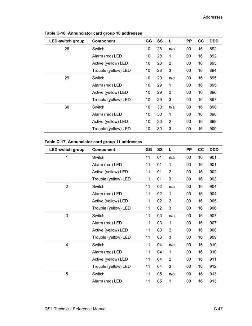
Addresses
QS1 Technical Reference Manual C.47
Table C-16: Annunciator card group 10 addresses
LED-switch group Component GG SS L PP CC DDD
28 Switch 10 28 n/a 00 16 892
Alarm (red) LED 10 28 1 00 16 892
Active (yellow) LED 10 28 2 00 16 893
Trouble (yellow) LED 10 28 3 00 16 894
29 Switch 10 29 n/a 00 16 895
Alarm (red) LED 10 29 1 00 16 895
Active (yellow) LED 10 29 2 00 16 896
Trouble (yellow) LED 10 29 3 00 16 897
30 Switch 10 30 n/a 00 16 898
Alarm (red) LED 10 30 1 00 16 898
Active (yellow) LED 10 30 2 00 16 899
Trouble (yellow) LED 10 30 3 00 16 900
Table C-17: Annunciator card group 11 addresses
LED-switch group Component GG SS L PP CC DDD
1 Switch 11 01 n/a 00 16 901
Alarm (red) LED 11 01 1 00 16 901
Active (yellow) LED 11 01 2 00 16 902
Trouble (yellow) LED 11 01 3 00 16 903
2 Switch 11 02 n/a 00 16 904
Alarm (red) LED 11 02 1 00 16 904
Active (yellow) LED 11 02 2 00 16 905
Trouble (yellow) LED 11 02 3 00 16 906
3 Switch 11 03 n/a 00 16 907
Alarm (red) LED 11 03 1 00 16 907
Active (yellow) LED 11 03 2 00 16 908
Trouble (yellow) LED 11 03 3 00 16 909
4 Switch 11 04 n/a 00 16 910
Alarm (red) LED 11 04 1 00 16 910
Active (yellow) LED 11 04 2 00 16 911
Trouble (yellow) LED 11 04 3 00 16 912
5 Switch 11 05 n/a 00 16 913
Alarm (red) LED 11 05 1 00 16 913
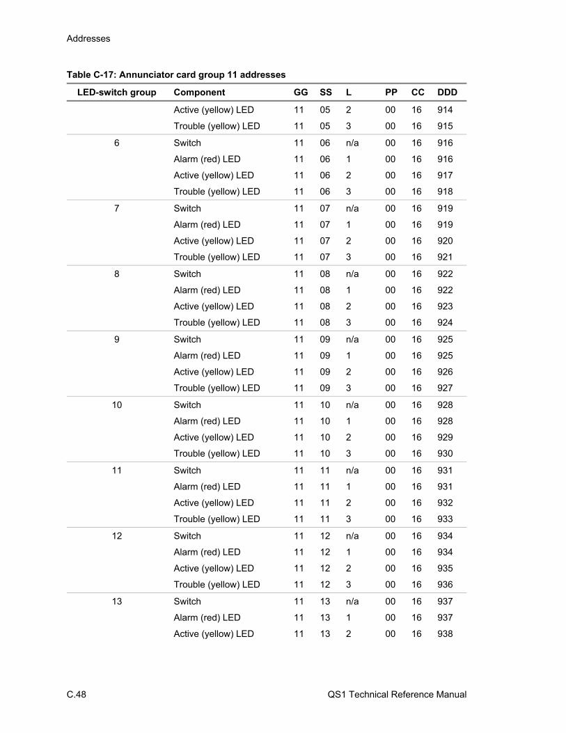
Addresses
C.48 QS1 Technical Reference Manual
Table C-17: Annunciator card group 11 addresses
LED-switch group Component GG SS L PP CC DDD
Active (yellow) LED 11 05 2 00 16 914
Trouble (yellow) LED 11 05 3 00 16 915
6 Switch 11 06 n/a 00 16 916
Alarm (red) LED 11 06 1 00 16 916
Active (yellow) LED 11 06 2 00 16 917
Trouble (yellow) LED 11 06 3 00 16 918
7 Switch 11 07 n/a 00 16 919
Alarm (red) LED 11 07 1 00 16 919
Active (yellow) LED 11 07 2 00 16 920
Trouble (yellow) LED 11 07 3 00 16 921
8 Switch 11 08 n/a 00 16 922
Alarm (red) LED 11 08 1 00 16 922
Active (yellow) LED 11 08 2 00 16 923
Trouble (yellow) LED 11 08 3 00 16 924
9 Switch 11 09 n/a 00 16 925
Alarm (red) LED 11 09 1 00 16 925
Active (yellow) LED 11 09 2 00 16 926
Trouble (yellow) LED 11 09 3 00 16 927
10 Switch 11 10 n/a 00 16 928
Alarm (red) LED 11 10 1 00 16 928
Active (yellow) LED 11 10 2 00 16 929
Trouble (yellow) LED 11 10 3 00 16 930
11 Switch 11 11 n/a 00 16 931
Alarm (red) LED 11 11 1 00 16 931
Active (yellow) LED 11 11 2 00 16 932
Trouble (yellow) LED 11 11 3 00 16 933
12 Switch 11 12 n/a 00 16 934
Alarm (red) LED 11 12 1 00 16 934
Active (yellow) LED 11 12 2 00 16 935
Trouble (yellow) LED 11 12 3 00 16 936
13 Switch 11 13 n/a 00 16 937
Alarm (red) LED 11 13 1 00 16 937
Active (yellow) LED 11 13 2 00 16 938

Addresses
QS1 Technical Reference Manual C.49
Table C-17: Annunciator card group 11 addresses
LED-switch group Component GG SS L PP CC DDD
Trouble (yellow) LED 11 13 3 00 16 939
14 Switch 11 14 n/a 00 16 940
Alarm (red) LED 11 14 1 00 16 940
Active (yellow) LED 11 14 2 00 16 941
Trouble (yellow) LED 11 14 3 00 16 942
15 Switch 11 15 n/a 00 16 943
Alarm (red) LED 11 15 1 00 16 943
Active (yellow) LED 11 15 2 00 16 944
Trouble (yellow) LED 11 15 3 00 16 945
16 Switch 11 16 n/a 00 16 946
Alarm (red) LED 11 16 1 00 16 946
Active (yellow) LED 11 16 2 00 16 947
Trouble (yellow) LED 11 16 3 00 16 948
17 Switch 11 17 n/a 00 16 949
Alarm (red) LED 11 17 1 00 16 949
Active (yellow) LED 11 17 2 00 16 950
Trouble (yellow) LED 11 17 3 00 16 951
18 Switch 11 18 n/a 00 16 952
Alarm (red) LED 11 18 1 00 16 952
Active (yellow) LED 11 18 2 00 16 953
Trouble (yellow) LED 11 18 3 00 16 954
19 Switch 11 19 n/a 00 16 955
Alarm (red) LED 11 19 1 00 16 955
Active (yellow) LED 11 19 2 00 16 956
Trouble (yellow) LED 11 19 3 00 16 957
20 Switch 11 20 n/a 00 16 958
Alarm (red) LED 11 20 1 00 16 958
Active (yellow) LED 11 20 2 00 16 959
Trouble (yellow) LED 11 20 3 00 16 960
21 Switch 11 21 n/a 00 16 961
Alarm (red) LED 11 21 1 00 16 961
Active (yellow) LED 11 21 2 00 16 962
Trouble (yellow) LED 11 21 3 00 16 963
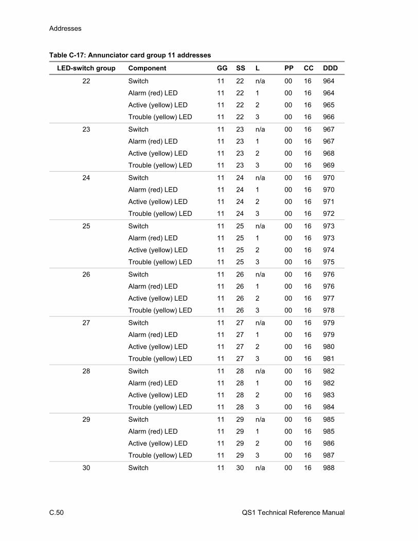
Addresses
C.50 QS1 Technical Reference Manual
Table C-17: Annunciator card group 11 addresses
LED-switch group Component GG SS L PP CC DDD
22 Switch 11 22 n/a 00 16 964
Alarm (red) LED 11 22 1 00 16 964
Active (yellow) LED 11 22 2 00 16 965
Trouble (yellow) LED 11 22 3 00 16 966
23 Switch 11 23 n/a 00 16 967
Alarm (red) LED 11 23 1 00 16 967
Active (yellow) LED 11 23 2 00 16 968
Trouble (yellow) LED 11 23 3 00 16 969
24 Switch 11 24 n/a 00 16 970
Alarm (red) LED 11 24 1 00 16 970
Active (yellow) LED 11 24 2 00 16 971
Trouble (yellow) LED 11 24 3 00 16 972
25 Switch 11 25 n/a 00 16 973
Alarm (red) LED 11 25 1 00 16 973
Active (yellow) LED 11 25 2 00 16 974
Trouble (yellow) LED 11 25 3 00 16 975
26 Switch 11 26 n/a 00 16 976
Alarm (red) LED 11 26 1 00 16 976
Active (yellow) LED 11 26 2 00 16 977
Trouble (yellow) LED 11 26 3 00 16 978
27 Switch 11 27 n/a 00 16 979
Alarm (red) LED 11 27 1 00 16 979
Active (yellow) LED 11 27 2 00 16 980
Trouble (yellow) LED 11 27 3 00 16 981
28 Switch 11 28 n/a 00 16 982
Alarm (red) LED 11 28 1 00 16 982
Active (yellow) LED 11 28 2 00 16 983
Trouble (yellow) LED 11 28 3 00 16 984
29 Switch 11 29 n/a 00 16 985
Alarm (red) LED 11 29 1 00 16 985
Active (yellow) LED 11 29 2 00 16 986
Trouble (yellow) LED 11 29 3 00 16 987
30 Switch 11 30 n/a 00 16 988
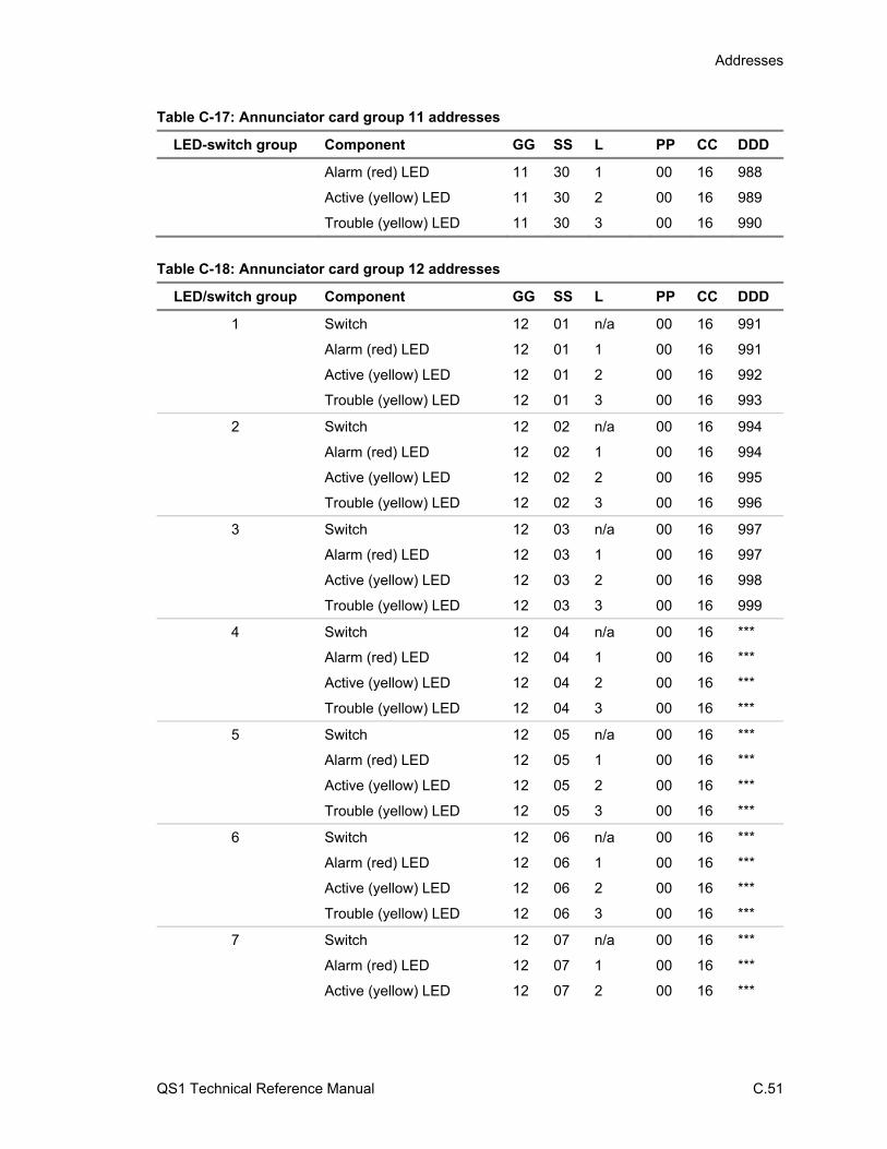
Addresses
QS1 Technical Reference Manual C.51
Table C-17: Annunciator card group 11 addresses
LED-switch group Component GG SS L PP CC DDD
Alarm (red) LED 11 30 1 00 16 988
Active (yellow) LED 11 30 2 00 16 989
Trouble (yellow) LED 11 30 3 00 16 990
Table C-18: Annunciator card group 12 addresses
LED/switch group Component GG SS L PP CC DDD
1 Switch 12 01 n/a 00 16 991
Alarm (red) LED 12 01 1 00 16 991
Active (yellow) LED 12 01 2 00 16 992
Trouble (yellow) LED 12 01 3 00 16 993
2 Switch 12 02 n/a 00 16 994
Alarm (red) LED 12 02 1 00 16 994
Active (yellow) LED 12 02 2 00 16 995
Trouble (yellow) LED 12 02 3 00 16 996
3 Switch 12 03 n/a 00 16 997
Alarm (red) LED 12 03 1 00 16 997
Active (yellow) LED 12 03 2 00 16 998
Trouble (yellow) LED 12 03 3 00 16 999
4 Switch 12 04 n/a 00 16 ***
Alarm (red) LED 12 04 1 00 16 ***
Active (yellow) LED 12 04 2 00 16 ***
Trouble (yellow) LED 12 04 3 00 16 ***
5 Switch 12 05 n/a 00 16 ***
Alarm (red) LED 12 05 1 00 16 ***
Active (yellow) LED 12 05 2 00 16 ***
Trouble (yellow) LED 12 05 3 00 16 ***
6 Switch 12 06 n/a 00 16 ***
Alarm (red) LED 12 06 1 00 16 ***
Active (yellow) LED 12 06 2 00 16 ***
Trouble (yellow) LED 12 06 3 00 16 ***
7 Switch 12 07 n/a 00 16 ***
Alarm (red) LED 12 07 1 00 16 ***
Active (yellow) LED 12 07 2 00 16 ***

Addresses
C.52 QS1 Technical Reference Manual
Table C-18: Annunciator card group 12 addresses
LED/switch group Component GG SS L PP CC DDD
Trouble (yellow) LED 12 07 3 00 16 ***
8 Switch 12 08 n/a 00 16 ***
Alarm (red) LED 12 08 1 00 16 ***
Active (yellow) LED 12 08 2 00 16 ***
Trouble (yellow) LED 12 08 3 00 16 ***
9 Switch 12 09 n/a 00 16 ***
Alarm (red) LED 12 09 1 00 16 ***
Active (yellow) LED 12 09 2 00 16 ***
Trouble (yellow) LED 12 09 3 00 16 ***
10 Switch 12 10 n/a 00 16 ***
Alarm (red) LED 12 10 1 00 16 ***
Active (yellow) LED 12 10 2 00 16 ***
Trouble (yellow) LED 12 10 3 00 16 ***
11 Switch 12 11 n/a 00 16 ***
Alarm (red) LED 12 11 1 00 16 ***
Active (yellow) LED 12 11 2 00 16 ***
Trouble (yellow) LED 12 11 3 00 16 ***
12 Switch 12 12 n/a 00 16 ***
Alarm (red) LED 12 12 1 00 16 ***
Active (yellow) LED 12 12 2 00 16 ***
Trouble (yellow) LED 12 12 3 00 16 ***
13 Switch 12 13 n/a 00 16 ***
Alarm (red) LED 12 13 1 00 16 ***
Active (yellow) LED 12 13 2 00 16 ***
Trouble (yellow) LED 12 13 3 00 16 ***
14 Switch 12 14 n/a 00 16 ***
Alarm (red) LED 12 14 1 00 16 ***
Active (yellow) LED 12 14 2 00 16 ***
Trouble (yellow) LED 12 14 3 00 16 ***
15 Switch 12 15 n/a 00 16 ***
Alarm (red) LED 12 15 1 00 16 ***
Active (yellow) LED 12 15 2 00 16 ***
Trouble (yellow) LED 12 15 3 00 16 ***

Addresses
QS1 Technical Reference Manual C.53
Table C-18: Annunciator card group 12 addresses
LED/switch group Component GG SS L PP CC DDD
16 Switch 12 16 n/a 00 16 ***
Alarm (red) LED 12 16 1 00 16 ***
Active (yellow) LED 12 16 2 00 16 ***
Trouble (yellow) LED 12 16 3 00 16 ***
17 Switch 12 17 n/a 00 16 ***
Alarm (red) LED 12 17 1 00 16 ***
Active (yellow) LED 12 17 2 00 16 ***
Trouble (yellow) LED 12 17 3 00 16 ***
18 Switch 12 18 n/a 00 16 ***
Alarm (red) LED 12 18 1 00 16 ***
Active (yellow) LED 12 18 2 00 16 ***
Trouble (yellow) LED 12 18 3 00 16 ***
19 Switch 12 19 n/a 00 16 ***
Alarm (red) LED 12 19 1 00 16 ***
Active (yellow) LED 12 19 2 00 16 ***
Trouble (yellow) LED 12 19 3 00 16 ***
20 Switch 12 20 n/a 00 16 ***
Alarm (red) LED 12 20 1 00 16 ***
Active (yellow) LED 12 20 2 00 16 ***
Trouble (yellow) LED 12 20 3 00 16 ***
21 Switch 12 21 n/a 00 16 ***
Alarm (red) LED 12 21 1 00 16 ***
Active (yellow) LED 12 21 2 00 16 ***
Trouble (yellow) LED 12 21 3 00 16 ***
22 Switch 12 22 n/a 00 16 ***
Alarm (red) LED 12 22 1 00 16 ***
Active (yellow) LED 12 22 2 00 16 ***
Trouble (yellow) LED 12 22 3 00 16 ***
23 Switch 12 23 n/a 00 16 ***
Alarm (red) LED 12 23 1 00 16 ***
Active (yellow) LED 12 23 2 00 16 ***
Trouble (yellow) LED 12 23 3 00 16 ***
24 Switch 12 24 n/a 00 16 ***
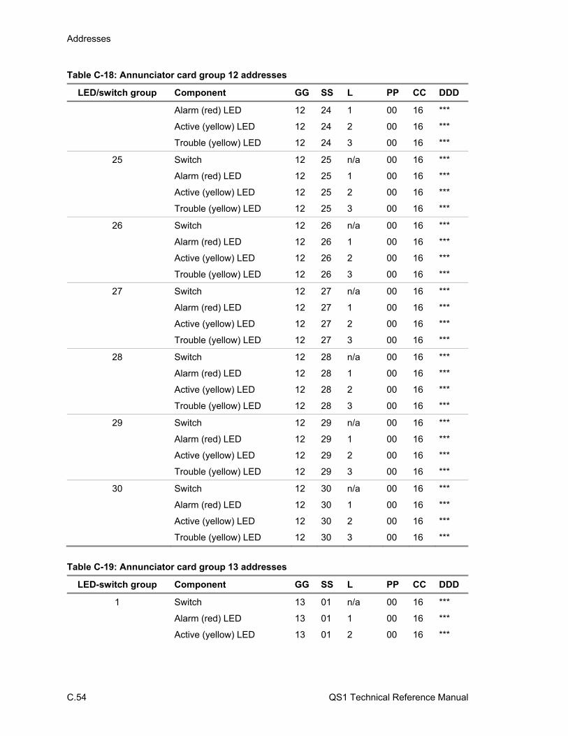
Addresses
C.54 QS1 Technical Reference Manual
Table C-18: Annunciator card group 12 addresses
LED/switch group Component GG SS L PP CC DDD
Alarm (red) LED 12 24 1 00 16 ***
Active (yellow) LED 12 24 2 00 16 ***
Trouble (yellow) LED 12 24 3 00 16 ***
25 Switch 12 25 n/a 00 16 ***
Alarm (red) LED 12 25 1 00 16 ***
Active (yellow) LED 12 25 2 00 16 ***
Trouble (yellow) LED 12 25 3 00 16 ***
26 Switch 12 26 n/a 00 16 ***
Alarm (red) LED 12 26 1 00 16 ***
Active (yellow) LED 12 26 2 00 16 ***
Trouble (yellow) LED 12 26 3 00 16 ***
27 Switch 12 27 n/a 00 16 ***
Alarm (red) LED 12 27 1 00 16 ***
Active (yellow) LED 12 27 2 00 16 ***
Trouble (yellow) LED 12 27 3 00 16 ***
28 Switch 12 28 n/a 00 16 ***
Alarm (red) LED 12 28 1 00 16 ***
Active (yellow) LED 12 28 2 00 16 ***
Trouble (yellow) LED 12 28 3 00 16 ***
29 Switch 12 29 n/a 00 16 ***
Alarm (red) LED 12 29 1 00 16 ***
Active (yellow) LED 12 29 2 00 16 ***
Trouble (yellow) LED 12 29 3 00 16 ***
30 Switch 12 30 n/a 00 16 ***
Alarm (red) LED 12 30 1 00 16 ***
Active (yellow) LED 12 30 2 00 16 ***
Trouble (yellow) LED 12 30 3 00 16 ***
Table C-19: Annunciator card group 13 addresses
LED-switch group Component GG SS L PP CC DDD
1 Switch 13 01 n/a 00 16 ***
Alarm (red) LED 13 01 1 00 16 ***
Active (yellow) LED 13 01 2 00 16 ***

Addresses
QS1 Technical Reference Manual C.55
Table C-19: Annunciator card group 13 addresses
LED-switch group Component GG SS L PP CC DDD
Trouble (yellow) LED 13 01 3 00 16 ***
2 Switch 13 02 n/a 00 16 ***
Alarm (red) LED 13 02 1 00 16 ***
Active (yellow) LED 13 02 2 00 16 ***
Trouble (yellow) LED 13 02 3 00 16 ***
3 Switch 13 03 n/a 00 16 ***
Alarm (red) LED 13 03 1 00 16 ***
Active (yellow) LED 13 03 2 00 16 ***
Trouble (yellow) LED 13 03 3 00 16 ***
4 Switch 13 04 n/a 00 16 ***
Alarm (red) LED 13 04 1 00 16 ***
Active (yellow) LED 13 04 2 00 16 ***
Trouble (yellow) LED 13 04 3 00 16 ***
5 Switch 13 05 n/a 00 16 ***
Alarm (red) LED 13 05 1 00 16 ***
Active (yellow) LED 13 05 2 00 16 ***
Trouble (yellow) LED 13 05 3 00 16 ***
6 Switch 13 06 n/a 00 16 ***
Alarm (red) LED 13 06 1 00 16 ***
Active (yellow) LED 13 06 2 00 16 ***
Trouble (yellow) LED 13 06 3 00 16 ***
7 Switch 13 07 n/a 00 16 ***
Alarm (red) LED 13 07 1 00 16 ***
Active (yellow) LED 13 07 2 00 16 ***
Trouble (yellow) LED 13 07 3 00 16 ***
8 Switch 13 08 n/a 00 16 ***
Alarm (red) LED 13 08 1 00 16 ***
Active (yellow) LED 13 08 2 00 16 ***
Trouble (yellow) LED 13 08 3 00 16 ***
9 Switch 13 09 n/a 00 16 ***
Alarm (red) LED 13 09 1 00 16 ***
Active (yellow) LED 13 09 2 00 16 ***
Trouble (yellow) LED 13 09 3 00 16 ***

Addresses
C.56 QS1 Technical Reference Manual
Table C-19: Annunciator card group 13 addresses
LED-switch group Component GG SS L PP CC DDD
10 Switch 13 10 n/a 00 16 ***
Alarm (red) LED 13 10 1 00 16 ***
Active (yellow) LED 13 10 2 00 16 ***
Trouble (yellow) LED 13 10 3 00 16 ***
11 Switch 13 11 n/a 00 16 ***
Alarm (red) LED 13 11 1 00 16 ***
Active (yellow) LED 13 11 2 00 16 ***
Trouble (yellow) LED 13 11 3 00 16 ***
12 Switch 13 12 n/a 00 16 ***
Alarm (red) LED 13 12 1 00 16 ***
Active (yellow) LED 13 12 2 00 16 ***
Trouble (yellow) LED 13 12 3 00 16 ***
13 Switch 13 13 n/a 00 16 ***
Alarm (red) LED 13 13 1 00 16 ***
Active (yellow) LED 13 13 2 00 16 ***
Trouble (yellow) LED 13 13 3 00 16 ***
14 Switch 13 14 n/a 00 16 ***
Alarm (red) LED 13 14 1 00 16 ***
Active (yellow) LED 13 14 2 00 16 ***
Trouble (yellow) LED 13 14 3 00 16 ***
15 Switch 13 15 n/a 00 16 ***
Alarm (red) LED 13 15 1 00 16 ***
Active (yellow) LED 13 15 2 00 16 ***
Trouble (yellow) LED 13 15 3 00 16 ***
16 Switch 13 16 n/a 00 16 ***
Alarm (red) LED 13 16 1 00 16 ***
Active (yellow) LED 13 16 2 00 16 ***
Trouble (yellow) LED 13 16 3 00 16 ***
17 Switch 13 17 n/a 00 16 ***
Alarm (red) LED 13 17 1 00 16 ***
Active (yellow) LED 13 17 2 00 16 ***
Trouble (yellow) LED 13 17 3 00 16 ***
18 Switch 13 18 n/a 00 16 ***

Addresses
QS1 Technical Reference Manual C.57
Table C-19: Annunciator card group 13 addresses
LED-switch group Component GG SS L PP CC DDD
Alarm (red) LED 13 18 1 00 16 ***
Active (yellow) LED 13 18 2 00 16 ***
Trouble (yellow) LED 13 18 3 00 16 ***
19 Switch 13 19 n/a 00 16 ***
Alarm (red) LED 13 19 1 00 16 ***
Active (yellow) LED 13 19 2 00 16 ***
Trouble (yellow) LED 13 19 3 00 16 ***
20 Switch 13 20 n/a 00 16 ***
Alarm (red) LED 13 20 1 00 16 ***
Active (yellow) LED 13 20 2 00 16 ***
Trouble (yellow) LED 13 20 3 00 16 ***
21 Switch 13 21 n/a 00 16 ***
Alarm (red) LED 13 21 1 00 16 ***
Active (yellow) LED 13 21 2 00 16 ***
Trouble (yellow) LED 13 21 3 00 16 ***
22 Switch 13 22 n/a 00 16 ***
Alarm (red) LED 13 22 1 00 16 ***
Active (yellow) LED 13 22 2 00 16 ***
Trouble (yellow) LED 13 22 3 00 16 ***
23 Switch 13 23 n/a 00 16 ***
Alarm (red) LED 13 23 1 00 16 ***
Active (yellow) LED 13 23 2 00 16 ***
Trouble (yellow) LED 13 23 3 00 16 ***
24 Switch 13 24 n/a 00 16 ***
Alarm (red) LED 13 24 1 00 16 ***
Active (yellow) LED 13 24 2 00 16 ***
Trouble (yellow) LED 13 24 3 00 16 ***
25 Switch 13 25 n/a 00 16 ***
Alarm (red) LED 13 25 1 00 16 ***
Active (yellow) LED 13 25 2 00 16 ***
Trouble (yellow) LED 13 25 3 00 16 ***
26 Switch 13 26 n/a 00 16 ***
Alarm (red) LED 13 26 1 00 16 ***
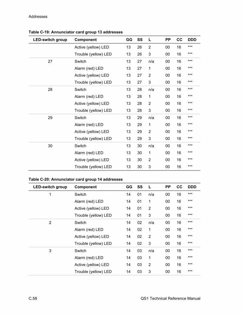
Addresses
C.58 QS1 Technical Reference Manual
Table C-19: Annunciator card group 13 addresses
LED-switch group Component GG SS L PP CC DDD
Active (yellow) LED 13 26 2 00 16 ***
Trouble (yellow) LED 13 26 3 00 16 ***
27 Switch 13 27 n/a 00 16 ***
Alarm (red) LED 13 27 1 00 16 ***
Active (yellow) LED 13 27 2 00 16 ***
Trouble (yellow) LED 13 27 3 00 16 ***
28 Switch 13 28 n/a 00 16 ***
Alarm (red) LED 13 28 1 00 16 ***
Active (yellow) LED 13 28 2 00 16 ***
Trouble (yellow) LED 13 28 3 00 16 ***
29 Switch 13 29 n/a 00 16 ***
Alarm (red) LED 13 29 1 00 16 ***
Active (yellow) LED 13 29 2 00 16 ***
Trouble (yellow) LED 13 29 3 00 16 ***
30 Switch 13 30 n/a 00 16 ***
Alarm (red) LED 13 30 1 00 16 ***
Active (yellow) LED 13 30 2 00 16 ***
Trouble (yellow) LED 13 30 3 00 16 ***
Table C-20: Annunciator card group 14 addresses
LED-switch group Component GG SS L PP CC DDD
1 Switch 14 01 n/a 00 16 ***
Alarm (red) LED 14 01 1 00 16 ***
Active (yellow) LED 14 01 2 00 16 ***
Trouble (yellow) LED 14 01 3 00 16 ***
2 Switch 14 02 n/a 00 16 ***
Alarm (red) LED 14 02 1 00 16 ***
Active (yellow) LED 14 02 2 00 16 ***
Trouble (yellow) LED 14 02 3 00 16 ***
3 Switch 14 03 n/a 00 16 ***
Alarm (red) LED 14 03 1 00 16 ***
Active (yellow) LED 14 03 2 00 16 ***
Trouble (yellow) LED 14 03 3 00 16 ***
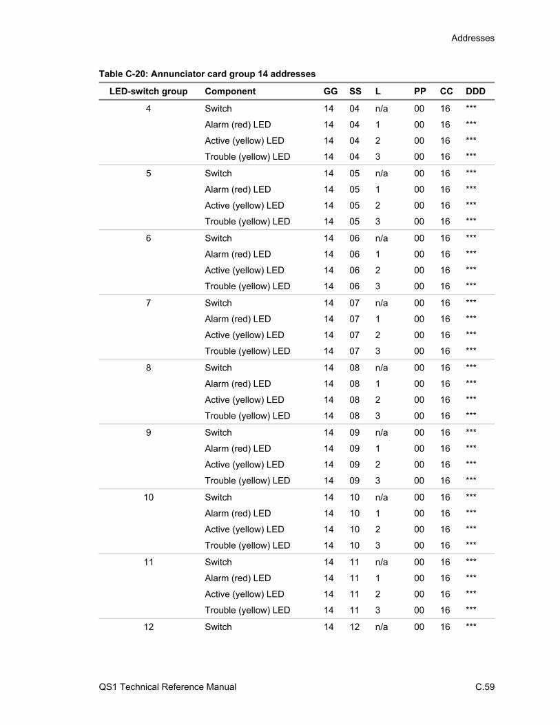
Addresses
QS1 Technical Reference Manual C.59
Table C-20: Annunciator card group 14 addresses
LED-switch group Component GG SS L PP CC DDD
4 Switch 14 04 n/a 00 16 ***
Alarm (red) LED 14 04 1 00 16 ***
Active (yellow) LED 14 04 2 00 16 ***
Trouble (yellow) LED 14 04 3 00 16 ***
5 Switch 14 05 n/a 00 16 ***
Alarm (red) LED 14 05 1 00 16 ***
Active (yellow) LED 14 05 2 00 16 ***
Trouble (yellow) LED 14 05 3 00 16 ***
6 Switch 14 06 n/a 00 16 ***
Alarm (red) LED 14 06 1 00 16 ***
Active (yellow) LED 14 06 2 00 16 ***
Trouble (yellow) LED 14 06 3 00 16 ***
7 Switch 14 07 n/a 00 16 ***
Alarm (red) LED 14 07 1 00 16 ***
Active (yellow) LED 14 07 2 00 16 ***
Trouble (yellow) LED 14 07 3 00 16 ***
8 Switch 14 08 n/a 00 16 ***
Alarm (red) LED 14 08 1 00 16 ***
Active (yellow) LED 14 08 2 00 16 ***
Trouble (yellow) LED 14 08 3 00 16 ***
9 Switch 14 09 n/a 00 16 ***
Alarm (red) LED 14 09 1 00 16 ***
Active (yellow) LED 14 09 2 00 16 ***
Trouble (yellow) LED 14 09 3 00 16 ***
10 Switch 14 10 n/a 00 16 ***
Alarm (red) LED 14 10 1 00 16 ***
Active (yellow) LED 14 10 2 00 16 ***
Trouble (yellow) LED 14 10 3 00 16 ***
11 Switch 14 11 n/a 00 16 ***
Alarm (red) LED 14 11 1 00 16 ***
Active (yellow) LED 14 11 2 00 16 ***
Trouble (yellow) LED 14 11 3 00 16 ***
12 Switch 14 12 n/a 00 16 ***
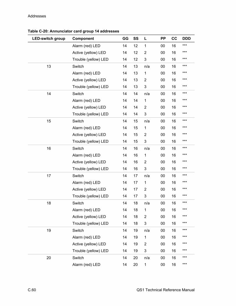
Addresses
C.60 QS1 Technical Reference Manual
Table C-20: Annunciator card group 14 addresses
LED-switch group Component GG SS L PP CC DDD
Alarm (red) LED 14 12 1 00 16 ***
Active (yellow) LED 14 12 2 00 16 ***
Trouble (yellow) LED 14 12 3 00 16 ***
13 Switch 14 13 n/a 00 16 ***
Alarm (red) LED 14 13 1 00 16 ***
Active (yellow) LED 14 13 2 00 16 ***
Trouble (yellow) LED 14 13 3 00 16 ***
14 Switch 14 14 n/a 00 16 ***
Alarm (red) LED 14 14 1 00 16 ***
Active (yellow) LED 14 14 2 00 16 ***
Trouble (yellow) LED 14 14 3 00 16 ***
15 Switch 14 15 n/a 00 16 ***
Alarm (red) LED 14 15 1 00 16 ***
Active (yellow) LED 14 15 2 00 16 ***
Trouble (yellow) LED 14 15 3 00 16 ***
16 Switch 14 16 n/a 00 16 ***
Alarm (red) LED 14 16 1 00 16 ***
Active (yellow) LED 14 16 2 00 16 ***
Trouble (yellow) LED 14 16 3 00 16 ***
17 Switch 14 17 n/a 00 16 ***
Alarm (red) LED 14 17 1 00 16 ***
Active (yellow) LED 14 17 2 00 16 ***
Trouble (yellow) LED 14 17 3 00 16 ***
18 Switch 14 18 n/a 00 16 ***
Alarm (red) LED 14 18 1 00 16 ***
Active (yellow) LED 14 18 2 00 16 ***
Trouble (yellow) LED 14 18 3 00 16 ***
19 Switch 14 19 n/a 00 16 ***
Alarm (red) LED 14 19 1 00 16 ***
Active (yellow) LED 14 19 2 00 16 ***
Trouble (yellow) LED 14 19 3 00 16 ***
20 Switch 14 20 n/a 00 16 ***
Alarm (red) LED 14 20 1 00 16 ***
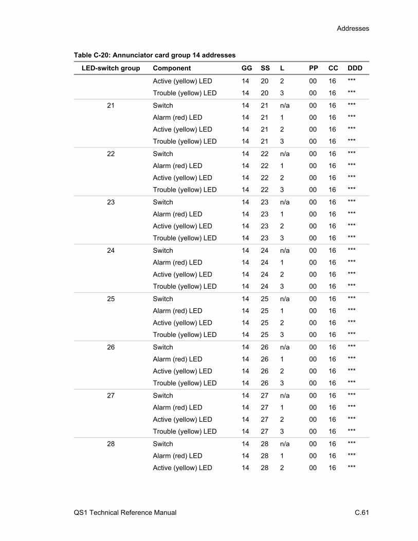
Addresses
QS1 Technical Reference Manual C.61
Table C-20: Annunciator card group 14 addresses
LED-switch group Component GG SS L PP CC DDD
Active (yellow) LED 14 20 2 00 16 ***
Trouble (yellow) LED 14 20 3 00 16 ***
21 Switch 14 21 n/a 00 16 ***
Alarm (red) LED 14 21 1 00 16 ***
Active (yellow) LED 14 21 2 00 16 ***
Trouble (yellow) LED 14 21 3 00 16 ***
22 Switch 14 22 n/a 00 16 ***
Alarm (red) LED 14 22 1 00 16 ***
Active (yellow) LED 14 22 2 00 16 ***
Trouble (yellow) LED 14 22 3 00 16 ***
23 Switch 14 23 n/a 00 16 ***
Alarm (red) LED 14 23 1 00 16 ***
Active (yellow) LED 14 23 2 00 16 ***
Trouble (yellow) LED 14 23 3 00 16 ***
24 Switch 14 24 n/a 00 16 ***
Alarm (red) LED 14 24 1 00 16 ***
Active (yellow) LED 14 24 2 00 16 ***
Trouble (yellow) LED 14 24 3 00 16 ***
25 Switch 14 25 n/a 00 16 ***
Alarm (red) LED 14 25 1 00 16 ***
Active (yellow) LED 14 25 2 00 16 ***
Trouble (yellow) LED 14 25 3 00 16 ***
26 Switch 14 26 n/a 00 16 ***
Alarm (red) LED 14 26 1 00 16 ***
Active (yellow) LED 14 26 2 00 16 ***
Trouble (yellow) LED 14 26 3 00 16 ***
27 Switch 14 27 n/a 00 16 ***
Alarm (red) LED 14 27 1 00 16 ***
Active (yellow) LED 14 27 2 00 16 ***
Trouble (yellow) LED 14 27 3 00 16 ***
28 Switch 14 28 n/a 00 16 ***
Alarm (red) LED 14 28 1 00 16 ***
Active (yellow) LED 14 28 2 00 16 ***
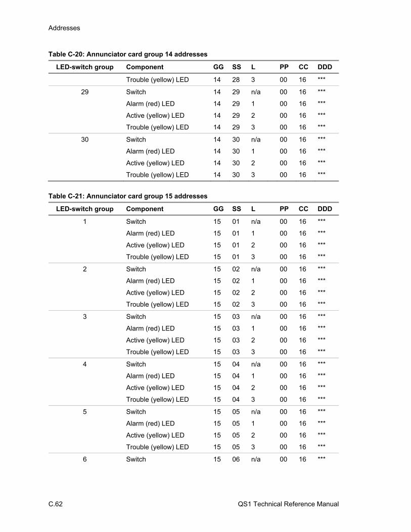
Addresses
C.62 QS1 Technical Reference Manual
Table C-20: Annunciator card group 14 addresses
LED-switch group Component GG SS L PP CC DDD
Trouble (yellow) LED 14 28 3 00 16 ***
29 Switch 14 29 n/a 00 16 ***
Alarm (red) LED 14 29 1 00 16 ***
Active (yellow) LED 14 29 2 00 16 ***
Trouble (yellow) LED 14 29 3 00 16 ***
30 Switch 14 30 n/a 00 16 ***
Alarm (red) LED 14 30 1 00 16 ***
Active (yellow) LED 14 30 2 00 16 ***
Trouble (yellow) LED 14 30 3 00 16 ***
Table C-21: Annunciator card group 15 addresses
LED-switch group Component GG SS L PP CC DDD
1 Switch 15 01 n/a 00 16 ***
Alarm (red) LED 15 01 1 00 16 ***
Active (yellow) LED 15 01 2 00 16 ***
Trouble (yellow) LED 15 01 3 00 16 ***
2 Switch 15 02 n/a 00 16 ***
Alarm (red) LED 15 02 1 00 16 ***
Active (yellow) LED 15 02 2 00 16 ***
Trouble (yellow) LED 15 02 3 00 16 ***
3 Switch 15 03 n/a 00 16 ***
Alarm (red) LED 15 03 1 00 16 ***
Active (yellow) LED 15 03 2 00 16 ***
Trouble (yellow) LED 15 03 3 00 16 ***
4 Switch 15 04 n/a 00 16 ***
Alarm (red) LED 15 04 1 00 16 ***
Active (yellow) LED 15 04 2 00 16 ***
Trouble (yellow) LED 15 04 3 00 16 ***
5 Switch 15 05 n/a 00 16 ***
Alarm (red) LED 15 05 1 00 16 ***
Active (yellow) LED 15 05 2 00 16 ***
Trouble (yellow) LED 15 05 3 00 16 ***
6 Switch 15 06 n/a 00 16 ***

Addresses
QS1 Technical Reference Manual C.63
Table C-21: Annunciator card group 15 addresses
LED-switch group Component GG SS L PP CC DDD
Alarm (red) LED 15 06 1 00 16 ***
Active (yellow) LED 15 06 2 00 16 ***
Trouble (yellow) LED 15 06 3 00 16 ***
7 Switch 15 07 n/a 00 16 ***
Alarm (red) LED 15 07 1 00 16 ***
Active (yellow) LED 15 07 2 00 16 ***
Trouble (yellow) LED 15 07 3 00 16 ***
8 Switch 15 08 n/a 00 16 ***
Alarm (red) LED 15 08 1 00 16 ***
Active (yellow) LED 15 08 2 00 16 ***
Trouble (yellow) LED 15 08 3 00 16 ***
9 Switch 15 09 n/a 00 16 ***
Alarm (red) LED 15 09 1 00 16 ***
Active (yellow) LED 15 09 2 00 16 ***
Trouble (yellow) LED 15 09 3 00 16 ***
10 Switch 15 10 n/a 00 16 ***
Alarm (red) LED 15 10 1 00 16 ***
Active (yellow) LED 15 10 2 00 16 ***
Trouble (yellow) LED 15 10 3 00 16 ***
11 Switch 15 11 n/a 00 16 ***
Alarm (red) LED 15 11 1 00 16 ***
Active (yellow) LED 15 11 2 00 16 ***
Trouble (yellow) LED 15 11 3 00 16 ***
12 Switch 15 12 n/a 00 16 ***
Alarm (red) LED 15 12 1 00 16 ***
Active (yellow) LED 15 12 2 00 16 ***
Trouble (yellow) LED 15 12 3 00 16 ***
13 Switch 15 13 n/a 00 16 ***
Alarm (red) LED 15 13 1 00 16 ***
Active (yellow) LED 15 13 2 00 16 ***
Trouble (yellow) LED 15 13 3 00 16 ***
14 Switch 15 14 n/a 00 16 ***
Alarm (red) LED 15 14 1 00 16 ***

Addresses
C.64 QS1 Technical Reference Manual
Table C-21: Annunciator card group 15 addresses
LED-switch group Component GG SS L PP CC DDD
Active (yellow) LED 15 14 2 00 16 ***
Trouble (yellow) LED 15 14 3 00 16 ***
15 Switch 15 15 n/a 00 16 ***
Alarm (red) LED 15 15 1 00 16 ***
Active (yellow) LED 15 15 2 00 16 ***
Trouble (yellow) LED 15 15 3 00 16 ***
16 Switch 15 16 n/a 00 16 ***
Alarm (red) LED 15 16 1 00 16 ***
Active (yellow) LED 15 16 2 00 16 ***
Trouble (yellow) LED 15 16 3 00 16 ***
17 Switch 15 17 n/a 00 16 ***
Alarm (red) LED 15 17 1 00 16 ***
Active (yellow) LED 15 17 2 00 16 ***
Trouble (yellow) LED 15 17 3 00 16 ***
18 Switch 15 18 n/a 00 16 ***
Alarm (red) LED 15 18 1 00 16 ***
Active (yellow) LED 15 18 2 00 16 ***
Trouble (yellow) LED 15 18 3 00 16 ***
19 Switch 15 19 n/a 00 16 ***
Alarm (red) LED 15 19 1 00 16 ***
Active (yellow) LED 15 19 2 00 16 ***
Trouble (yellow) LED 15 19 3 00 16 ***
20 Switch 15 20 n/a 00 16 ***
Alarm (red) LED 15 20 1 00 16 ***
Active (yellow) LED 15 20 2 00 16 ***
Trouble (yellow) LED 15 20 3 00 16 ***
21 Switch 15 21 n/a 00 16 ***
Alarm (red) LED 15 21 1 00 16 ***
Active (yellow) LED 15 21 2 00 16 ***
Trouble (yellow) LED 15 21 3 00 16 ***
22 Switch 15 22 n/a 00 16 ***
Alarm (red) LED 15 22 1 00 16 ***
Active (yellow) LED 15 22 2 00 16 ***

Addresses
QS1 Technical Reference Manual C.65
Table C-21: Annunciator card group 15 addresses
LED-switch group Component GG SS L PP CC DDD
Trouble (yellow) LED 15 22 3 00 16 ***
23 Switch 15 23 n/a 00 16 ***
Alarm (red) LED 15 23 1 00 16 ***
Active (yellow) LED 15 23 2 00 16 ***
Trouble (yellow) LED 15 23 3 00 16 ***
24 Switch 15 24 n/a 00 16 ***
Alarm (red) LED 15 24 1 00 16 ***
Active (yellow) LED 15 24 2 00 16 ***
Trouble (yellow) LED 15 24 3 00 16 ***
25 Switch 15 25 n/a 00 16 ***
Alarm (red) LED 15 25 1 00 16 ***
Active (yellow) LED 15 25 2 00 16 ***
Trouble (yellow) LED 15 25 3 00 16 ***
26 Switch 15 26 n/a 00 16 ***
Alarm (red) LED 15 26 1 00 16 ***
Active (yellow) LED 15 26 2 00 16 ***
Trouble (yellow) LED 15 26 3 00 16 ***
27 Switch 15 27 n/a 00 16 ***
Alarm (red) LED 15 27 1 00 16 ***
Active (yellow) LED 15 27 2 00 16 ***
Trouble (yellow) LED 15 27 3 00 16 ***
28 Switch 15 28 n/a 00 16 ***
Alarm (red) LED 15 28 1 00 16 ***
Active (yellow) LED 15 28 2 00 16 ***
Trouble (yellow) LED 15 28 3 00 16 ***
29 Switch 15 29 n/a 00 16 ***
Alarm (red) LED 15 29 1 00 16 ***
Active (yellow) LED 15 29 2 00 16 ***
Trouble (yellow) LED 15 29 3 00 16 ***
30 Switch 15 30 n/a 00 16 ***
Alarm (red) LED 15 30 1 00 16 ***
Active (yellow) LED 15 30 2 00 16 ***
Trouble (yellow) LED 15 30 3 00 16 ***
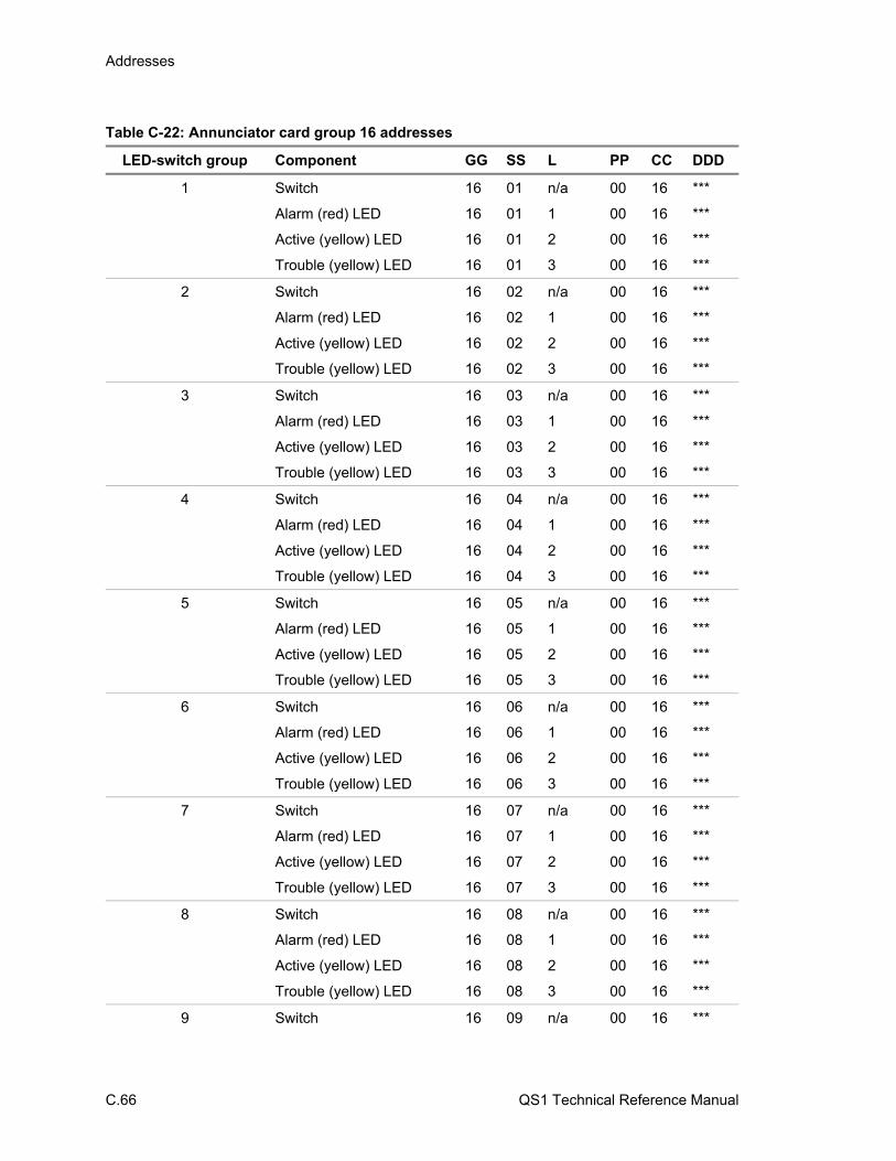
Addresses
C.66 QS1 Technical Reference Manual
Table C-22: Annunciator card group 16 addresses
LED-switch group Component GG SS L PP CC DDD
1 Switch 16 01 n/a 00 16 ***
Alarm (red) LED 16 01 1 00 16 ***
Active (yellow) LED 16 01 2 00 16 ***
Trouble (yellow) LED 16 01 3 00 16 ***
2 Switch 16 02 n/a 00 16 ***
Alarm (red) LED 16 02 1 00 16 ***
Active (yellow) LED 16 02 2 00 16 ***
Trouble (yellow) LED 16 02 3 00 16 ***
3 Switch 16 03 n/a 00 16 ***
Alarm (red) LED 16 03 1 00 16 ***
Active (yellow) LED 16 03 2 00 16 ***
Trouble (yellow) LED 16 03 3 00 16 ***
4 Switch 16 04 n/a 00 16 ***
Alarm (red) LED 16 04 1 00 16 ***
Active (yellow) LED 16 04 2 00 16 ***
Trouble (yellow) LED 16 04 3 00 16 ***
5 Switch 16 05 n/a 00 16 ***
Alarm (red) LED 16 05 1 00 16 ***
Active (yellow) LED 16 05 2 00 16 ***
Trouble (yellow) LED 16 05 3 00 16 ***
6 Switch 16 06 n/a 00 16 ***
Alarm (red) LED 16 06 1 00 16 ***
Active (yellow) LED 16 06 2 00 16 ***
Trouble (yellow) LED 16 06 3 00 16 ***
7 Switch 16 07 n/a 00 16 ***
Alarm (red) LED 16 07 1 00 16 ***
Active (yellow) LED 16 07 2 00 16 ***
Trouble (yellow) LED 16 07 3 00 16 ***
8 Switch 16 08 n/a 00 16 ***
Alarm (red) LED 16 08 1 00 16 ***
Active (yellow) LED 16 08 2 00 16 ***
Trouble (yellow) LED 16 08 3 00 16 ***
9 Switch 16 09 n/a 00 16 ***
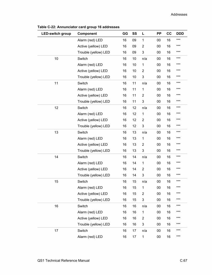
Addresses
QS1 Technical Reference Manual C.67
Table C-22: Annunciator card group 16 addresses
LED-switch group Component GG SS L PP CC DDD
Alarm (red) LED 16 09 1 00 16 ***
Active (yellow) LED 16 09 2 00 16 ***
Trouble (yellow) LED 16 09 3 00 16 ***
10 Switch 16 10 n/a 00 16 ***
Alarm (red) LED 16 10 1 00 16 ***
Active (yellow) LED 16 10 2 00 16 ***
Trouble (yellow) LED 16 10 3 00 16 ***
11 Switch 16 11 n/a 00 16 ***
Alarm (red) LED 16 11 1 00 16 ***
Active (yellow) LED 16 11 2 00 16 ***
Trouble (yellow) LED 16 11 3 00 16 ***
12 Switch 16 12 n/a 00 16 ***
Alarm (red) LED 16 12 1 00 16 ***
Active (yellow) LED 16 12 2 00 16 ***
Trouble (yellow) LED 16 12 3 00 16 ***
13 Switch 16 13 n/a 00 16 ***
Alarm (red) LED 16 13 1 00 16 ***
Active (yellow) LED 16 13 2 00 16 ***
Trouble (yellow) LED 16 13 3 00 16 ***
14 Switch 16 14 n/a 00 16 ***
Alarm (red) LED 16 14 1 00 16 ***
Active (yellow) LED 16 14 2 00 16 ***
Trouble (yellow) LED 16 14 3 00 16 ***
15 Switch 16 15 n/a 00 16 ***
Alarm (red) LED 16 15 1 00 16 ***
Active (yellow) LED 16 15 2 00 16 ***
Trouble (yellow) LED 16 15 3 00 16 ***
16 Switch 16 16 n/a 00 16 ***
Alarm (red) LED 16 16 1 00 16 ***
Active (yellow) LED 16 16 2 00 16 ***
Trouble (yellow) LED 16 16 3 00 16 ***
17 Switch 16 17 n/a 00 16 ***
Alarm (red) LED 16 17 1 00 16 ***

Addresses
C.68 QS1 Technical Reference Manual
Table C-22: Annunciator card group 16 addresses
LED-switch group Component GG SS L PP CC DDD
Active (yellow) LED 16 17 2 00 16 ***
Trouble (yellow) LED 16 17 3 00 16 ***
18 Switch 16 18 n/a 00 16 ***
Alarm (red) LED 16 18 1 00 16 ***
Active (yellow) LED 16 18 2 00 16 ***
Trouble (yellow) LED 16 18 3 00 16 ***
19 Switch 16 19 n/a 00 16 ***
Alarm (red) LED 16 19 1 00 16 ***
Active (yellow) LED 16 19 2 00 16 ***
Trouble (yellow) LED 16 19 3 00 16 ***
20 Switch 16 20 n/a 00 16 ***
Alarm (red) LED 16 20 1 00 16 ***
Active (yellow) LED 16 20 2 00 16 ***
Trouble (yellow) LED 16 20 3 00 16 ***
21 Switch 16 21 n/a 00 16 ***
Alarm (red) LED 16 21 1 00 16 ***
Active (yellow) LED 16 21 2 00 16 ***
Trouble (yellow) LED 16 21 3 00 16 ***
22 Switch 16 22 n/a 00 16 ***
Alarm (red) LED 16 22 1 00 16 ***
Active (yellow) LED 16 22 2 00 16 ***
Trouble (yellow) LED 16 22 3 00 16 ***
23 Switch 16 23 n/a 00 16 ***
Alarm (red) LED 16 23 1 00 16 ***
Active (yellow) LED 16 23 2 00 16 ***
Trouble (yellow) LED 16 23 3 00 16 ***
24 Switch 16 24 n/a 00 16 ***
Alarm (red) LED 16 24 1 00 16 ***
Active (yellow) LED 16 24 2 00 16 ***
Trouble (yellow) LED 16 24 3 00 16 ***
25 Switch 16 25 n/a 00 16 ***
Alarm (red) LED 16 25 1 00 16 ***
Active (yellow) LED 16 25 2 00 16 ***

Addresses
QS1 Technical Reference Manual C.69
Table C-22: Annunciator card group 16 addresses
LED-switch group Component GG SS L PP CC DDD
Trouble (yellow) LED 16 25 3 00 16 ***
26 Switch 16 26 n/a 00 16 ***
Alarm (red) LED 16 26 1 00 16 ***
Active (yellow) LED 16 26 2 00 16 ***
Trouble (yellow) LED 16 26 3 00 16 ***
27 Switch 16 27 n/a 00 16 ***
Alarm (red) LED 16 27 1 00 16 ***
Active (yellow) LED 16 27 2 00 16 ***
Trouble (yellow) LED 16 27 3 00 16 ***
28 Switch 16 28 n/a 00 16 ***
Alarm (red) LED 16 28 1 00 16 ***
Active (yellow) LED 16 28 2 00 16 ***
Trouble (yellow) LED 16 28 3 00 16 ***
29 Switch 16 29 n/a 00 16 ***
Alarm (red) LED 16 29 1 00 16 ***
Active (yellow) LED 16 29 2 00 16 ***
Trouble (yellow) LED 16 29 3 00 16 ***
30 Switch 16 30 n/a 00 16 ***
Alarm (red) LED 16 30 1 00 16 ***
Active (yellow) LED 16 30 2 00 16 ***
Trouble (yellow) LED 16 30 3 00 16 ***

Addresses
C.70 QS1 Technical Reference Manual

QS1 Technical Reference Manual D.1
Appendix D Contact ID event codes
Summary
This appendix provides a list of Contact ID event codes that you can use when programming dialer strings.
Content
Alarms • D.2 Supervisories • D.3 Troubles • D.4 Bypasses/disables • D.8 Test/miscellaneous • D.10
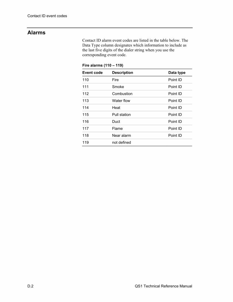
Contact ID event codes
D.2 QS1 Technical Reference Manual
Alarms Contact ID alarm event codes are listed in the table below. The Data Type column designates which information to include as the last five digits of the dialer string when you use the corresponding event code. Fire alarms (110 – 119)
Event code Description Data type
110 Fire Point ID
111 Smoke Point ID
112 Combustion Point ID
113 Water flow Point ID
114 Heat Point ID
115 Pull station Point ID
116 Duct Point ID
117 Flame Point ID
118 Near alarm Point ID
119 not defined
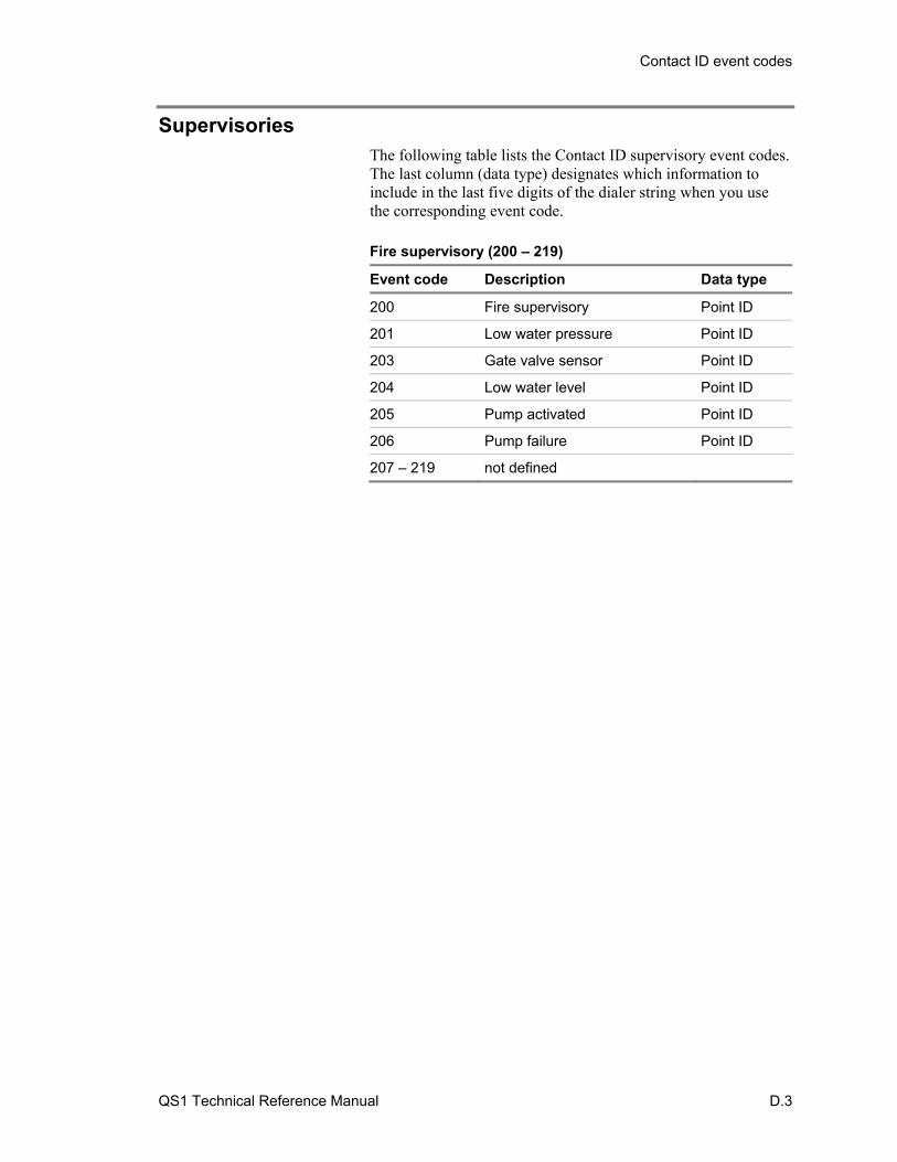
Contact ID event codes
QS1 Technical Reference Manual D.3
Supervisories The following table lists the Contact ID supervisory event codes. The last column (data type) designates which information to include in the last five digits of the dialer string when you use the corresponding event code. Fire supervisory (200 – 219)
Event code Description Data type
200 Fire supervisory Point ID
201 Low water pressure Point ID
203 Gate valve sensor Point ID
204 Low water level Point ID
205 Pump activated Point ID
206 Pump failure Point ID
207 – 219 not defined
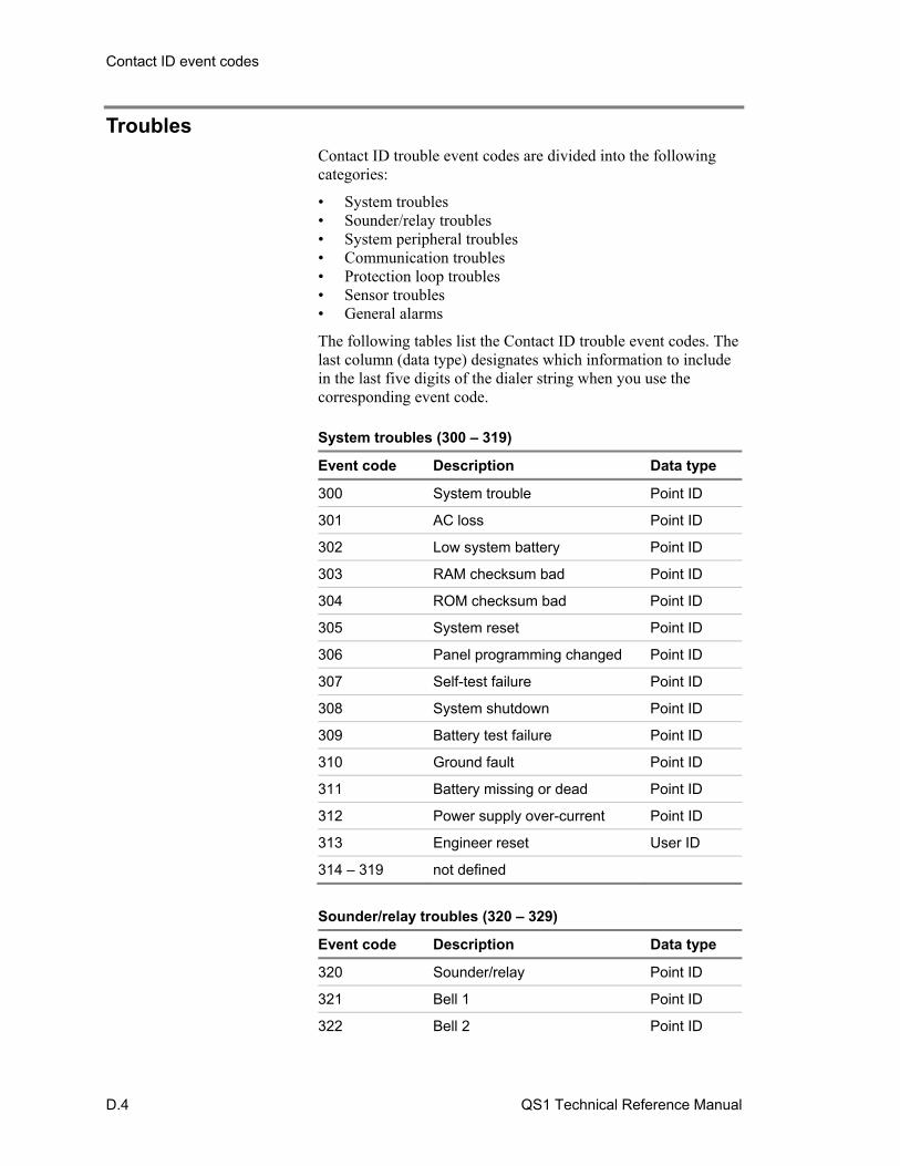
Contact ID event codes
D.4 QS1 Technical Reference Manual
Troubles Contact ID trouble event codes are divided into the following categories:
• System troubles • Sounder/relay troubles • System peripheral troubles • Communication troubles • Protection loop troubles • Sensor troubles • General alarms
The following tables list the Contact ID trouble event codes. The last column (data type) designates which information to include in the last five digits of the dialer string when you use the corresponding event code. System troubles (300 – 319)
Event code Description Data type
300 System trouble Point ID
301 AC loss Point ID
302 Low system battery Point ID
303 RAM checksum bad Point ID
304 ROM checksum bad Point ID
305 System reset Point ID
306 Panel programming changed Point ID
307 Self-test failure Point ID
308 System shutdown Point ID
309 Battery test failure Point ID
310 Ground fault Point ID
311 Battery missing or dead Point ID
312 Power supply over-current Point ID
313 Engineer reset User ID
314 – 319 not defined
Sounder/relay troubles (320 – 329)
Event code Description Data type
320 Sounder/relay Point ID
321 Bell 1 Point ID
322 Bell 2 Point ID
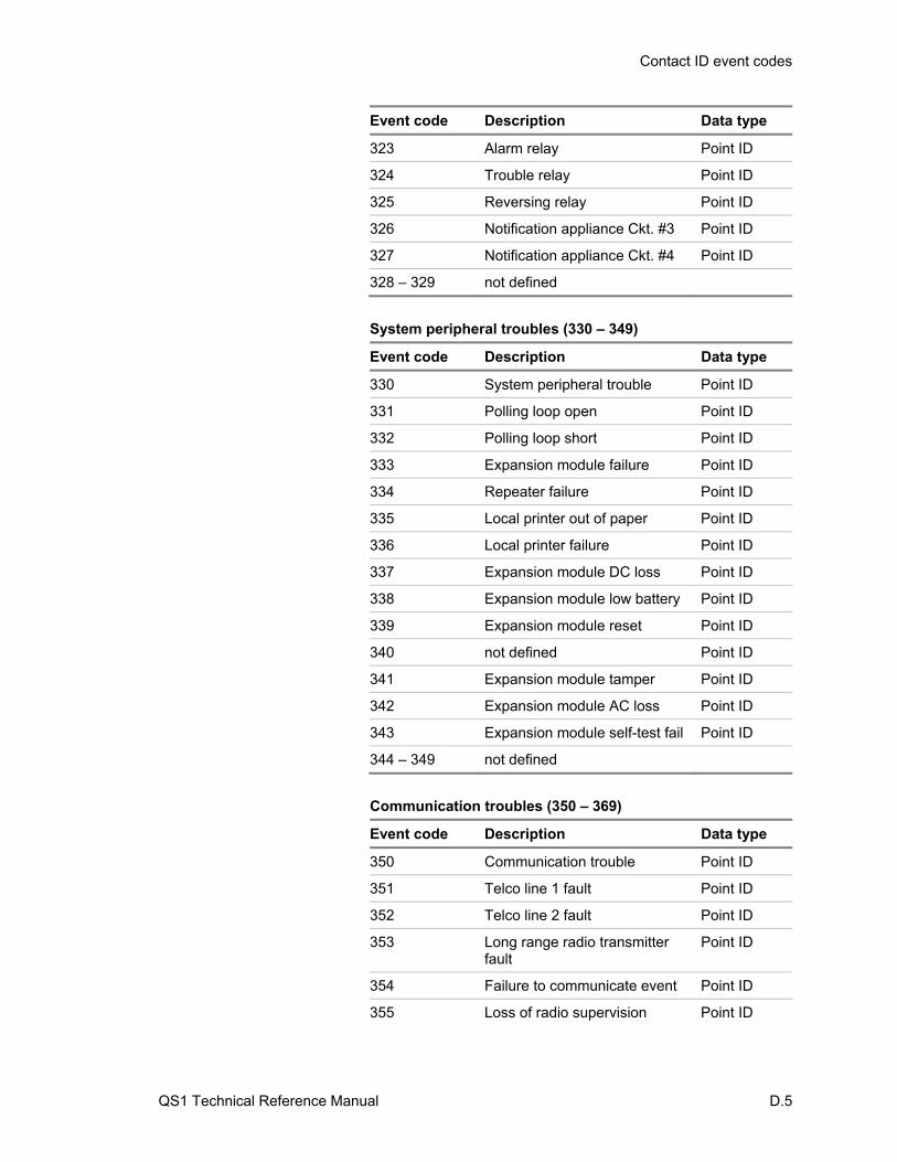
Contact ID event codes
QS1 Technical Reference Manual D.5
Event code Description Data type
323 Alarm relay Point ID
324 Trouble relay Point ID
325 Reversing relay Point ID
326 Notification appliance Ckt. #3 Point ID
327 Notification appliance Ckt. #4 Point ID
328 – 329 not defined
System peripheral troubles (330 – 349)
Event code Description Data type
330 System peripheral trouble Point ID
331 Polling loop open Point ID
332 Polling loop short Point ID
333 Expansion module failure Point ID
334 Repeater failure Point ID
335 Local printer out of paper Point ID
336 Local printer failure Point ID
337 Expansion module DC loss Point ID
338 Expansion module low battery Point ID
339 Expansion module reset Point ID
340 not defined Point ID
341 Expansion module tamper Point ID
342 Expansion module AC loss Point ID
343 Expansion module self-test fail Point ID
344 – 349 not defined
Communication troubles (350 – 369)
Event code Description Data type
350 Communication trouble Point ID
351 Telco line 1 fault Point ID
352 Telco line 2 fault Point ID
353 Long range radio transmitter fault
Point ID
354 Failure to communicate event Point ID
355 Loss of radio supervision Point ID

Contact ID event codes
D.6 QS1 Technical Reference Manual
Event code Description Data type
356 Loss of central polling Point ID
357 Long range radio VSWR problem
Point ID
358 – 369 not defined
Protection loop (370 – 379)
Event code Description Data type
370 Protection loop Point ID
371 Protection loop open Point ID
372 Protection loop short Point ID
373 Fire trouble Point ID
374 Exit error (zone) Point ID
375 Panel zone trouble Point ID
377 – 379 not defined
Sensor troubles (380 – 399)
Event code Description Data type
380 Sensor trouble Point ID
381 Loss of supervision - RF Point ID
382 Loss of supervision - RPM Point ID
383 Sensor tamper Point ID
384 RF low battery Point ID
385 Smoke detector high sensitivity Point ID
386 Smoke detector low sensitivity Point ID
387 Intrusion detector high sensitivity
Point ID
388 Intrusion detector low sensitivity
Point ID
389 Sensor self-test failure Point ID
390 not defined
391 Sensor watch trouble Point ID
392 Drift compensation error Point ID
393 Maintenance alert Point ID
394 – 399 not defined
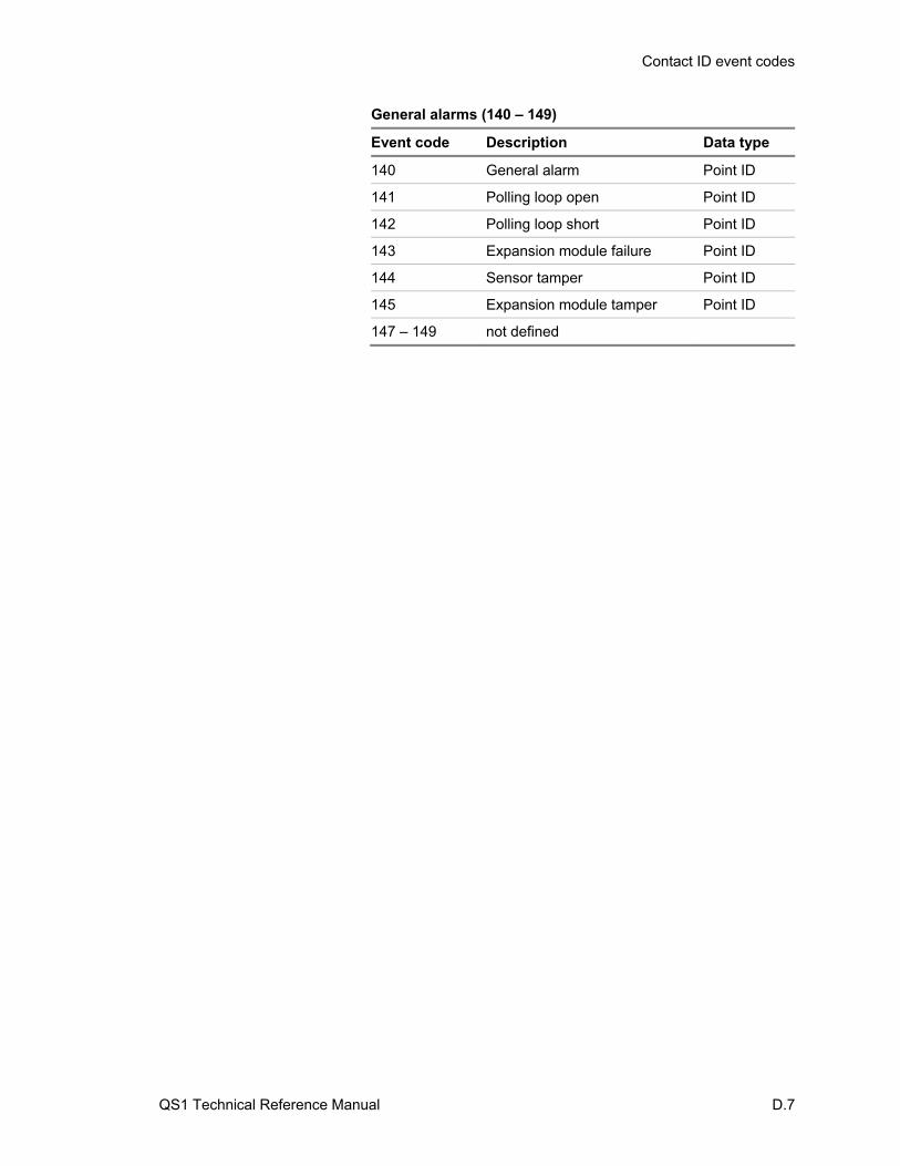
Contact ID event codes
QS1 Technical Reference Manual D.7
General alarms (140 – 149)
Event code Description Data type
140 General alarm Point ID
141 Polling loop open Point ID
142 Polling loop short Point ID
143 Expansion module failure Point ID
144 Sensor tamper Point ID
145 Expansion module tamper Point ID
147 – 149 not defined
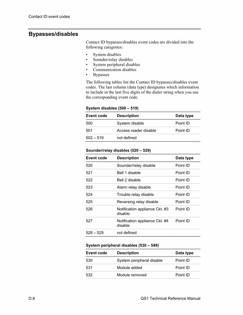
Contact ID event codes
D.8 QS1 Technical Reference Manual
Bypasses/disables Contact ID bypasses/disables event codes are divided into the following categories:
• System disables • Sounder/relay disables • System peripheral disables • Communication disables • Bypasses
The following tables list the Contact ID bypasses/disables event codes. The last column (data type) designates which information to include in the last five digits of the dialer string when you use the corresponding event code. System disables (500 – 519)
Event code Description Data type
500 System disable Point ID
501 Access reader disable Point ID
502 – 519 not defined
Sounder/relay disables (520 – 529)
Event code Description Data type
520 Sounder/relay disable Point ID
521 Bell 1 disable Point ID
522 Bell 2 disable Point ID
523 Alarm relay disable Point ID
524 Trouble relay disable Point ID
525 Reversing relay disable Point ID
526 Notification appliance Ckt. #3 disable
Point ID
527 Notification appliance Ckt. #4 disable
Point ID
528 – 529 not defined
System peripheral disables (530 – 549)
Event code Description Data type
530 System peripheral disable Point ID
531 Module added Point ID
532 Module removed Point ID
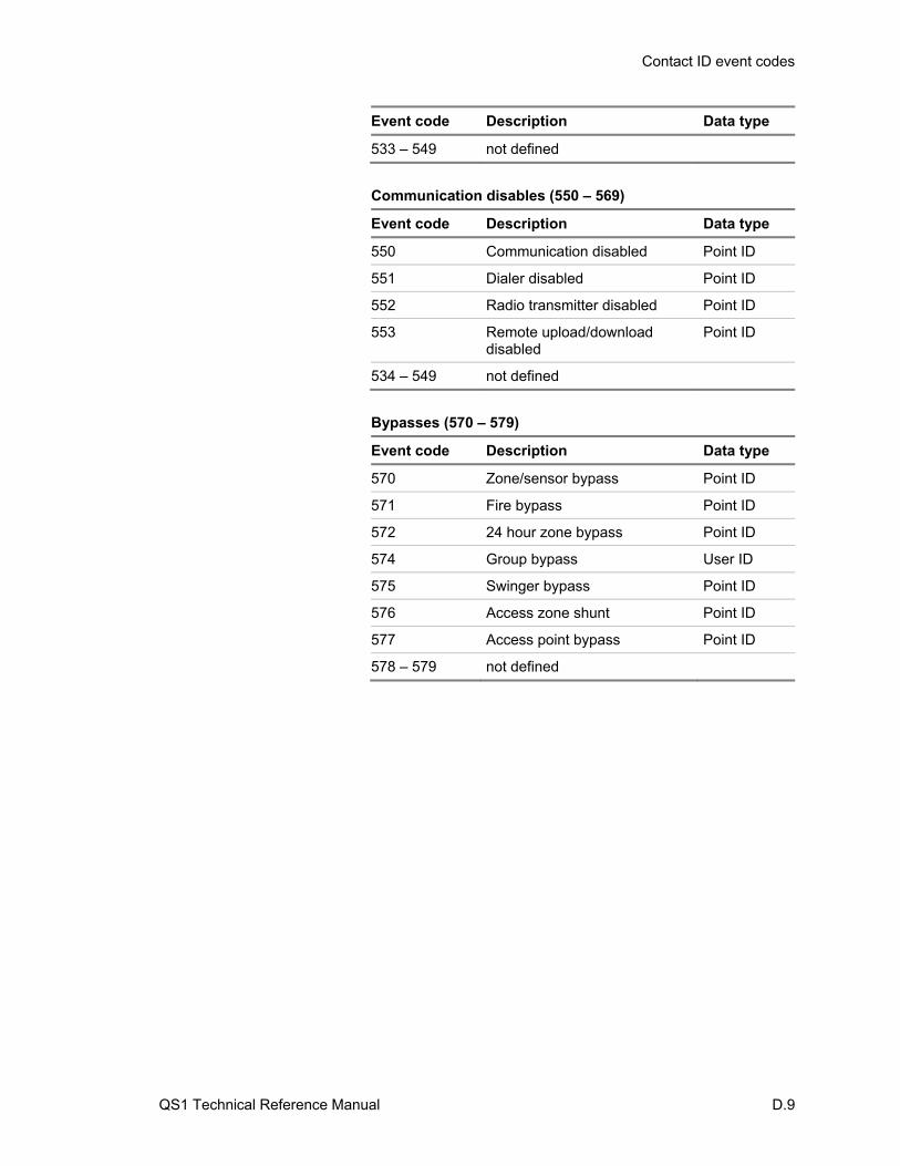
Contact ID event codes
QS1 Technical Reference Manual D.9
Event code Description Data type
533 – 549 not defined
Communication disables (550 – 569)
Event code Description Data type
550 Communication disabled Point ID
551 Dialer disabled Point ID
552 Radio transmitter disabled Point ID
553 Remote upload/download disabled
Point ID
534 – 549 not defined
Bypasses (570 – 579)
Event code Description Data type
570 Zone/sensor bypass Point ID
571 Fire bypass Point ID
572 24 hour zone bypass Point ID
574 Group bypass User ID
575 Swinger bypass Point ID
576 Access zone shunt Point ID
577 Access point bypass Point ID
578 – 579 not defined
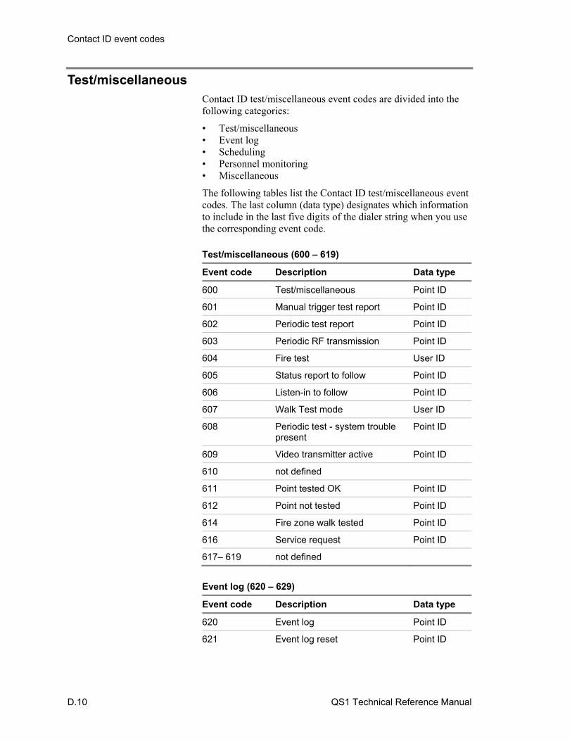
Contact ID event codes
D.10 QS1 Technical Reference Manual
Test/miscellaneous Contact ID test/miscellaneous event codes are divided into the following categories:
• Test/miscellaneous • Event log • Scheduling • Personnel monitoring • Miscellaneous
The following tables list the Contact ID test/miscellaneous event codes. The last column (data type) designates which information to include in the last five digits of the dialer string when you use the corresponding event code. Test/miscellaneous (600 – 619)
Event code Description Data type
600 Test/miscellaneous Point ID
601 Manual trigger test report Point ID
602 Periodic test report Point ID
603 Periodic RF transmission Point ID
604 Fire test User ID
605 Status report to follow Point ID
606 Listen-in to follow Point ID
607 Walk Test mode User ID
608 Periodic test - system trouble present
Point ID
609 Video transmitter active Point ID
610 not defined
611 Point tested OK Point ID
612 Point not tested Point ID
614 Fire zone walk tested Point ID
616 Service request Point ID
617– 619 not defined
Event log (620 – 629)
Event code Description Data type
620 Event log Point ID
621 Event log reset Point ID
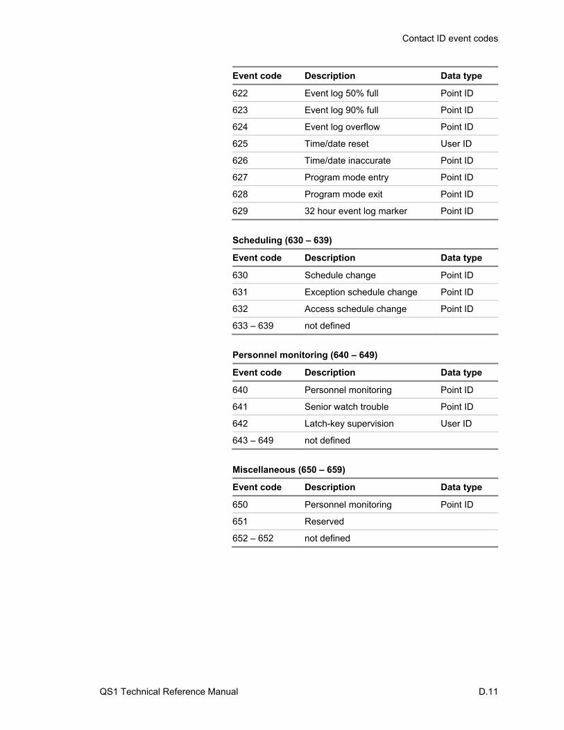
Contact ID event codes
QS1 Technical Reference Manual D.11
Event code Description Data type
622 Event log 50% full Point ID
623 Event log 90% full Point ID
624 Event log overflow Point ID
625 Time/date reset User ID
626 Time/date inaccurate Point ID
627 Program mode entry Point ID
628 Program mode exit Point ID
629 32 hour event log marker Point ID
Scheduling (630 – 639)
Event code Description Data type
630 Schedule change Point ID
631 Exception schedule change Point ID
632 Access schedule change Point ID
633 – 639 not defined
Personnel monitoring (640 – 649)
Event code Description Data type
640 Personnel monitoring Point ID
641 Senior watch trouble Point ID
642 Latch-key supervision User ID
643 – 649 not defined
Miscellaneous (650 – 659)
Event code Description Data type
650 Personnel monitoring Point ID
651 Reserved
652 – 652 not defined

Contact ID event codes
D.12 QS1 Technical Reference Manual
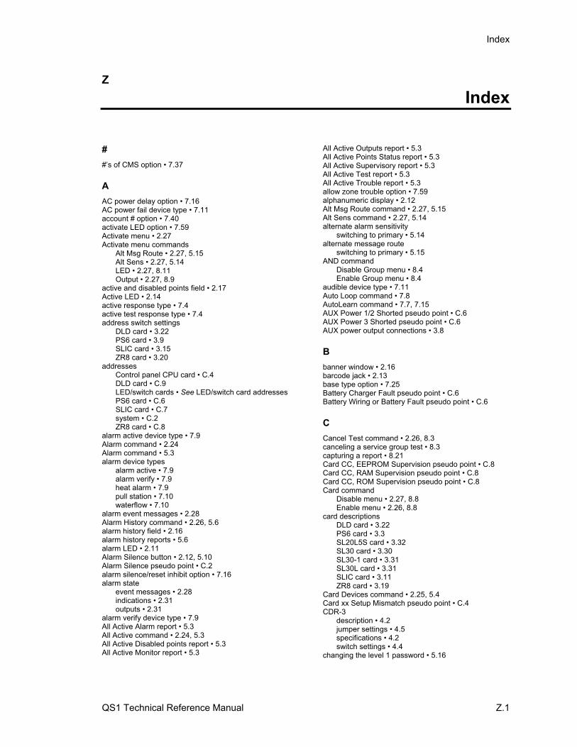
Index
QS1 Technical Reference Manual Z.1
Z Index
#
#’s of CMS option • 7.37
A
AC power delay option • 7.16 AC power fail device type • 7.11 account # option • 7.40 activate LED option • 7.59 Activate menu • 2.27 Activate menu commands
Alt Msg Route • 2.27, 5.15 Alt Sens • 2.27, 5.14 LED • 2.27, 8.11 Output • 2.27, 8.9
active and disabled points field • 2.17 Active LED • 2.14 active response type • 7.4 active test response type • 7.4 address switch settings
DLD card • 3.22 PS6 card • 3.9 SLIC card • 3.15 ZR8 card • 3.20
addresses Control panel CPU card • C.4 DLD card • C.9 LED/switch cards • See LED/switch card addresses PS6 card • C.6 SLIC card • C.7 system • C.2 ZR8 card • C.8
alarm active device type • 7.9 Alarm command • 2.24 Alarm command • 5.3 alarm device types
alarm active • 7.9 alarm verify • 7.9 heat alarm • 7.9 pull station • 7.10 waterflow • 7.10
alarm event messages • 2.28 Alarm History command • 2.26, 5.6 alarm history field • 2.16 alarm history reports • 5.6 alarm LED • 2.11 Alarm Silence button • 2.12, 5.10 Alarm Silence pseudo point • C.2 alarm silence/reset inhibit option • 7.16 alarm state
event messages • 2.28 indications • 2.31 outputs • 2.31
alarm verify device type • 7.9 All Active Alarm report • 5.3 All Active command • 2.24, 5.3 All Active Disabled points report • 5.3 All Active Monitor report • 5.3
All Active Outputs report • 5.3 All Active Points Status report • 5.3 All Active Supervisory report • 5.3 All Active Test report • 5.3 All Active Trouble report • 5.3 allow zone trouble option • 7.59 alphanumeric display • 2.12 Alt Msg Route command • 2.27, 5.15 Alt Sens command • 2.27, 5.14 alternate alarm sensitivity
switching to primary • 5.14 alternate message route
switching to primary • 5.15 AND command
Disable Group menu • 8.4 Enable Group menu • 8.4
audible device type • 7.11 Auto Loop command • 7.8 AutoLearn command • 7.7, 7.15 AUX Power 1/2 Shorted pseudo point • C.6 AUX Power 3 Shorted pseudo point • C.6 AUX power output connections • 3.8
B
banner window • 2.16 barcode jack • 2.13 base type option • 7.25 Battery Charger Fault pseudo point • C.6 Battery Wiring or Battery Fault pseudo point • C.6
C
Cancel Test command • 2.26, 8.3 canceling a service group test • 8.3 capturing a report • 8.21 Card CC, EEPROM Supervision pseudo point • C.8 Card CC, RAM Supervision pseudo point • C.8 Card CC, ROM Supervision pseudo point • C.8 Card command
Disable menu • 2.27, 8.8 Enable menu • 2.26, 8.8
card descriptions DLD card • 3.22 PS6 card • 3.3 SL20L5S card • 3.32 SL30 card • 3.30 SL30-1 card • 3.31 SL30L card • 3.31 SLIC card • 3.11 ZR8 card • 3.19
Card Devices command • 2.25, 5.4 Card xx Setup Mismatch pseudo point • C.4 CDR-3
description • 4.2 jumper settings • 4.5 specifications • 4.2 switch settings • 4.4
changing the level 1 password • 5.16
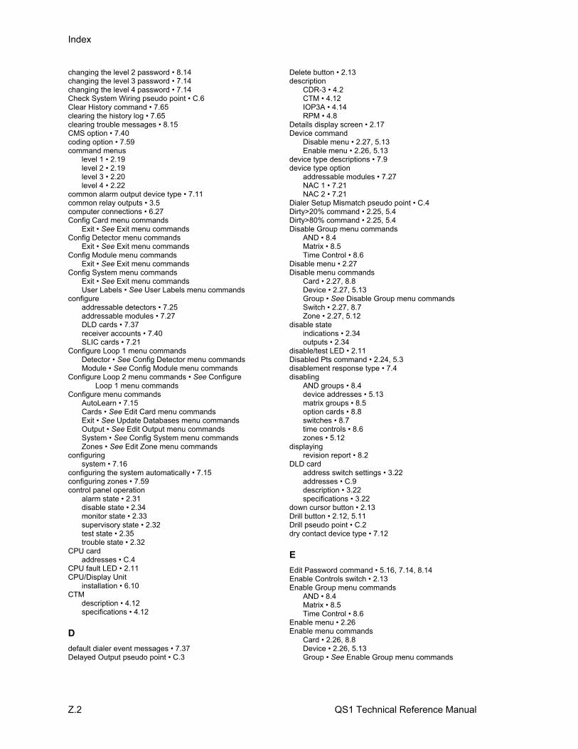
Index
Z.2 QS1 Technical Reference Manual
changing the level 2 password • 8.14 changing the level 3 password • 7.14 changing the level 4 password • 7.14 Check System Wiring pseudo point • C.6 Clear History command • 7.65 clearing the history log • 7.65 clearing trouble messages • 8.15 CMS option • 7.40 coding option • 7.59 command menus
level 1 • 2.19 level 2 • 2.19 level 3 • 2.20 level 4 • 2.22
common alarm output device type • 7.11 common relay outputs • 3.5 computer connections • 6.27 Config Card menu commands
Exit • See Exit menu commands Config Detector menu commands
Exit • See Exit menu commands Config Module menu commands
Exit • See Exit menu commands Config System menu commands
Exit • See Exit menu commands User Labels • See User Labels menu commands
configure addressable detectors • 7.25 addressable modules • 7.27 DLD cards • 7.37 receiver accounts • 7.40 SLIC cards • 7.21
Configure Loop 1 menu commands Detector • See Config Detector menu commands Module • See Config Module menu commands
Configure Loop 2 menu commands • See Configure Loop 1 menu commands
Configure menu commands AutoLearn • 7.15 Cards • See Edit Card menu commands Exit • See Update Databases menu commands Output • See Edit Output menu commands System • See Config System menu commands Zones • See Edit Zone menu commands
configuring system • 7.16
configuring the system automatically • 7.15 configuring zones • 7.59 control panel operation
alarm state • 2.31 disable state • 2.34 monitor state • 2.33 supervisory state • 2.32 test state • 2.35 trouble state • 2.32
CPU card addresses • C.4
CPU fault LED • 2.11 CPU/Display Unit
installation • 6.10 CTM
description • 4.12 specifications • 4.12
D
default dialer event messages • 7.37 Delayed Output pseudo point • C.3
Delete button • 2.13 description
CDR-3 • 4.2 CTM • 4.12 IOP3A • 4.14 RPM • 4.8
Details display screen • 2.17 Device command
Disable menu • 2.27, 5.13 Enable menu • 2.26, 5.13
device type descriptions • 7.9 device type option
addressable modules • 7.27 NAC 1 • 7.21 NAC 2 • 7.21
Dialer Setup Mismatch pseudo point • C.4 Dirty>20% command • 2.25, 5.4 Dirty>80% command • 2.25, 5.4 Disable Group menu commands
AND • 8.4 Matrix • 8.5 Time Control • 8.6
Disable menu • 2.27 Disable menu commands
Card • 2.27, 8.8 Device • 2.27, 5.13 Group • See Disable Group menu commands Switch • 2.27, 8.7 Zone • 2.27, 5.12
disable state indications • 2.34 outputs • 2.34
disable/test LED • 2.11 Disabled Pts command • 2.24, 5.3 disablement response type • 7.4 disabling
AND groups • 8.4 device addresses • 5.13 matrix groups • 8.5 option cards • 8.8 switches • 8.7 time controls • 8.6 zones • 5.12
displaying revision report • 8.2
DLD card address switch settings • 3.22 addresses • C.9 description • 3.22 specifications • 3.22
down cursor button • 2.13 Drill button • 2.12, 5.11 Drill pseudo point • C.2 dry contact device type • 7.12
E
Edit Password command • 5.16, 7.14, 8.14 Enable Controls switch • 2.13 Enable Group menu commands
AND • 8.4 Matrix • 8.5 Time Control • 8.6
Enable menu • 2.26 Enable menu commands
Card • 2.26, 8.8 Device • 2.26, 5.13 Group • See Enable Group menu commands
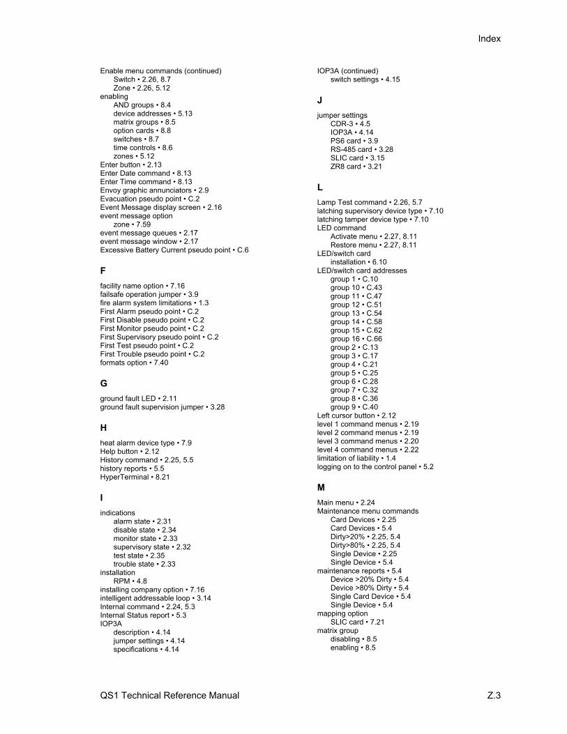
Index
QS1 Technical Reference Manual Z.3
Enable menu commands (continued) Switch • 2.26, 8.7 Zone • 2.26, 5.12
enabling AND groups • 8.4 device addresses • 5.13 matrix groups • 8.5 option cards • 8.8 switches • 8.7 time controls • 8.6 zones • 5.12
Enter button • 2.13 Enter Date command • 8.13 Enter Time command • 8.13 Envoy graphic annunciators • 2.9 Evacuation pseudo point • C.2 Event Message display screen • 2.16 event message option
zone • 7.59 event message queues • 2.17 event message window • 2.17 Excessive Battery Current pseudo point • C.6
F
facility name option • 7.16 failsafe operation jumper • 3.9 fire alarm system limitations • 1.3 First Alarm pseudo point • C.2 First Disable pseudo point • C.2 First Monitor pseudo point • C.2 First Supervisory pseudo point • C.2 First Test pseudo point • C.2 First Trouble pseudo point • C.2 formats option • 7.40
G
ground fault LED • 2.11 ground fault supervision jumper • 3.28
H
heat alarm device type • 7.9 Help button • 2.12 History command • 2.25, 5.5 history reports • 5.5 HyperTerminal • 8.21
I
indications alarm state • 2.31 disable state • 2.34 monitor state • 2.33 supervisory state • 2.32 test state • 2.35 trouble state • 2.33
installation RPM • 4.8
installing company option • 7.16 intelligent addressable loop • 3.14 Internal command • 2.24, 5.3 Internal Status report • 5.3 IOP3A
description • 4.14 jumper settings • 4.14 specifications • 4.14
IOP3A (continued) switch settings • 4.15
J
jumper settings CDR-3 • 4.5 IOP3A • 4.14 PS6 card • 3.9 RS-485 card • 3.28 SLIC card • 3.15 ZR8 card • 3.21
L
Lamp Test command • 2.26, 5.7 latching supervisory device type • 7.10 latching tamper device type • 7.10 LED command
Activate menu • 2.27, 8.11 Restore menu • 2.27, 8.11
LED/switch card installation • 6.10
LED/switch card addresses group 1 • C.10 group 10 • C.43 group 11 • C.47 group 12 • C.51 group 13 • C.54 group 14 • C.58 group 15 • C.62 group 16 • C.66 group 2 • C.13 group 3 • C.17 group 4 • C.21 group 5 • C.25 group 6 • C.28 group 7 • C.32 group 8 • C.36 group 9 • C.40
Left cursor button • 2.12 level 1 command menus • 2.19 level 2 command menus • 2.19 level 3 command menus • 2.20 level 4 command menus • 2.22 limitation of liability • 1.4 logging on to the control panel • 5.2
M
Main menu • 2.24 Maintenance menu commands
Card Devices • 2.25 Card Devices • 5.4 Dirty>20% • 2.25, 5.4 Dirty>80% • 2.25, 5.4 Single Device • 2.25 Single Device • 5.4
maintenance reports • 5.4 Device >20% Dirty • 5.4 Device >80% Dirty • 5.4 Single Card Device • 5.4 Single Device • 5.4
mapping option SLIC card • 7.21
matrix group disabling • 8.5 enabling • 8.5
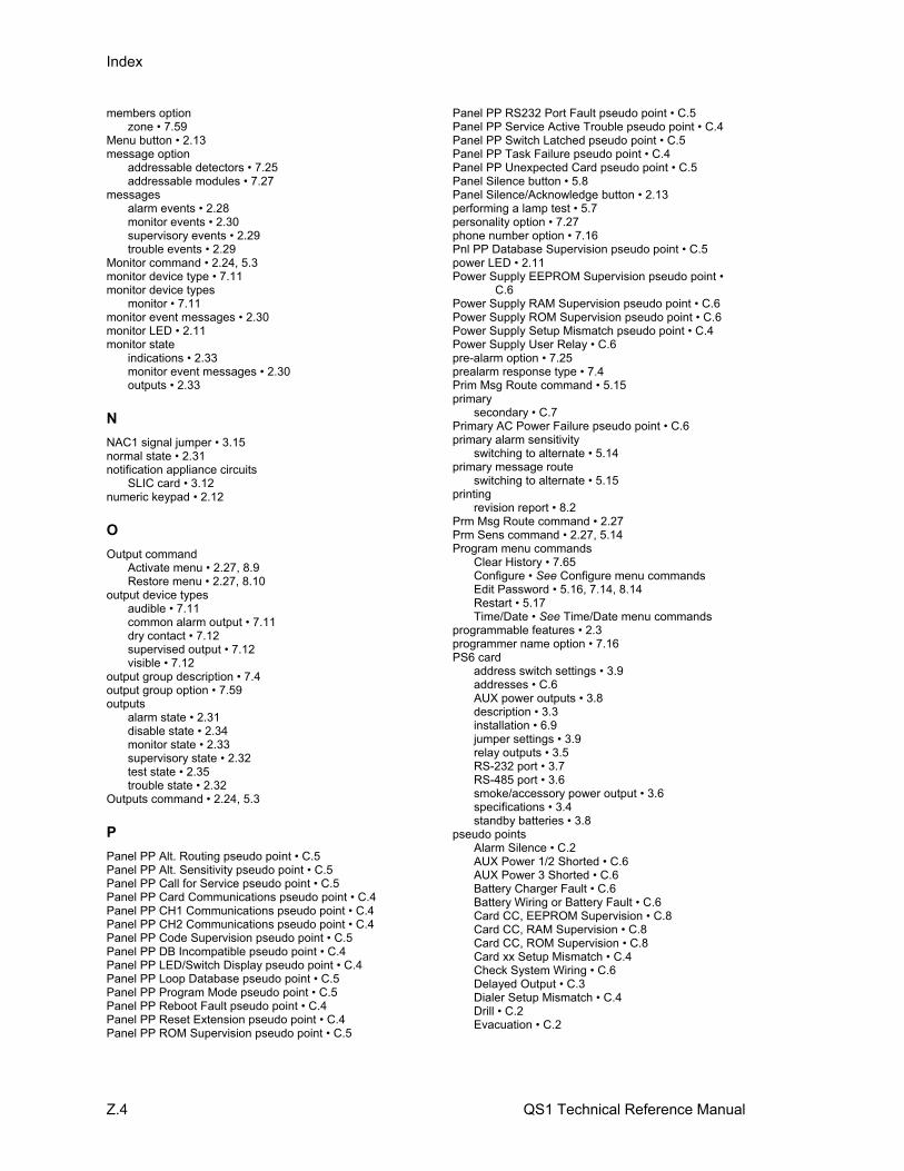
Index
Z.4 QS1 Technical Reference Manual
members option zone • 7.59
Menu button • 2.13 message option
addressable detectors • 7.25 addressable modules • 7.27
messages alarm events • 2.28 monitor events • 2.30 supervisory events • 2.29 trouble events • 2.29
Monitor command • 2.24, 5.3 monitor device type • 7.11 monitor device types
monitor • 7.11 monitor event messages • 2.30 monitor LED • 2.11 monitor state
indications • 2.33 monitor event messages • 2.30 outputs • 2.33
N
NAC1 signal jumper • 3.15 normal state • 2.31 notification appliance circuits
SLIC card • 3.12 numeric keypad • 2.12
O
Output command Activate menu • 2.27, 8.9 Restore menu • 2.27, 8.10
output device types audible • 7.11 common alarm output • 7.11 dry contact • 7.12 supervised output • 7.12 visible • 7.12
output group description • 7.4 output group option • 7.59 outputs
alarm state • 2.31 disable state • 2.34 monitor state • 2.33 supervisory state • 2.32 test state • 2.35 trouble state • 2.32
Outputs command • 2.24, 5.3
P
Panel PP Alt. Routing pseudo point • C.5 Panel PP Alt. Sensitivity pseudo point • C.5 Panel PP Call for Service pseudo point • C.5 Panel PP Card Communications pseudo point • C.4 Panel PP CH1 Communications pseudo point • C.4 Panel PP CH2 Communications pseudo point • C.4 Panel PP Code Supervision pseudo point • C.5 Panel PP DB Incompatible pseudo point • C.4 Panel PP LED/Switch Display pseudo point • C.4 Panel PP Loop Database pseudo point • C.5 Panel PP Program Mode pseudo point • C.5 Panel PP Reboot Fault pseudo point • C.4 Panel PP Reset Extension pseudo point • C.4 Panel PP ROM Supervision pseudo point • C.5
Panel PP RS232 Port Fault pseudo point • C.5 Panel PP Service Active Trouble pseudo point • C.4 Panel PP Switch Latched pseudo point • C.5 Panel PP Task Failure pseudo point • C.4 Panel PP Unexpected Card pseudo point • C.5 Panel Silence button • 5.8 Panel Silence/Acknowledge button • 2.13 performing a lamp test • 5.7 personality option • 7.27 phone number option • 7.16 Pnl PP Database Supervision pseudo point • C.5 power LED • 2.11 Power Supply EEPROM Supervision pseudo point •
C.6 Power Supply RAM Supervision pseudo point • C.6 Power Supply ROM Supervision pseudo point • C.6 Power Supply Setup Mismatch pseudo point • C.4 Power Supply User Relay • C.6 pre-alarm option • 7.25 prealarm response type • 7.4 Prim Msg Route command • 5.15 primary
secondary • C.7 Primary AC Power Failure pseudo point • C.6 primary alarm sensitivity
switching to alternate • 5.14 primary message route
switching to alternate • 5.15 printing
revision report • 8.2 Prm Msg Route command • 2.27 Prm Sens command • 2.27, 5.14 Program menu commands
Clear History • 7.65 Configure • See Configure menu commands Edit Password • 5.16, 7.14, 8.14 Restart • 5.17 Time/Date • See Time/Date menu commands
programmable features • 2.3 programmer name option • 7.16 PS6 card
address switch settings • 3.9 addresses • C.6 AUX power outputs • 3.8 description • 3.3 installation • 6.9 jumper settings • 3.9 relay outputs • 3.5 RS-232 port • 3.7 RS-485 port • 3.6 smoke/accessory power output • 3.6 specifications • 3.4 standby batteries • 3.8
pseudo points Alarm Silence • C.2 AUX Power 1/2 Shorted • C.6 AUX Power 3 Shorted • C.6 Battery Charger Fault • C.6 Battery Wiring or Battery Fault • C.6 Card CC, EEPROM Supervision • C.8 Card CC, RAM Supervision • C.8 Card CC, ROM Supervision • C.8 Card xx Setup Mismatch • C.4 Check System Wiring • C.6 Delayed Output • C.3 Dialer Setup Mismatch • C.4 Drill • C.2 Evacuation • C.2
Index
QS1 Technical Reference Manual Z.5
Excessive Battery Current • C.6 First Alarm • C.2 First Disable • C.2 First Monitor • C.2 First Supervisory • C.2 First Test • C.2 First Trouble • C.2 Panel PP Alt. Routing • C.5 Panel PP Alt. Sensitivity • C.5 Panel PP Call for Service • C.5 Panel PP Card Communications • C.4 Panel PP CH1 Communications • C.4 Panel PP CH2 Communications • C.4 Panel PP Code Supervision • C.5 Panel PP DB Incompatible • C.4 Panel PP LED/Switch Display • C.4 Panel PP Loop Database • C.5 Panel PP Program Mode • C.5 Panel PP Reboot Fault • C.4 Panel PP Reset Extension • C.4 Panel PP ROM Supervision • C.5 Panel PP RS232 Port Fault • C.5 Panel PP Service Active Trouble • C.4 Panel PP Switch Latched • C.5 Panel PP Task Failure • C.4 Panel PP Unexpected Card • C.5 Pnl PP Database Supervision • C.5 Power Supply EEPROM Supervision • C.6 Power Supply RAM Supervision • C.6 Power Supply ROM Supervision • C.6 Power Supply Setup Mismatch • C.4 Primary AC Power Failure • C.6 Reset • C.2 Reset Phase 1 • C.2 Reset Phase 2 • C.2 Reset Phase 3 • C.2 Smoke Power Shorted • C.6 Startup • C.2 Thermal Fault • C.6 Two Stage Expiration • C.2 Two Stage Timer Started • C.3 User Trouble • C.3
pull station device type • 7.10
R
R Series remote annunciators • 2.7 RAI card
installation • 6.18 wiring • 6.20
Rcvr 1 Prim # option • 7.37 Rcvr 1 Sec # option • 7.37 Rcvr 2 Prim # option • 7.37 Rcvr 2 Sec # option • 7.37 relay outputs
PS6 card • 3.5 ZR8 card • 3.20
remote annunciator installation • 6.15 remote station protective signaling system • 4.8 replacing the control panel fuse • 8.20 Reports menu • 2.24 Reports menu commands
Alarm History • 2.26, 5.6 History • 2.25, 5.5 Maintenance • See Maintenance menu commands Revisions • 2.25, 8.2
Reset Phase 1 pseudo point • C.2 Reset Phase 2 pseudo point • C.2
Reset Phase 3 pseudo point • C.2 Reset pseudo point • C.2 resetting the alarm history counter • 7.65 resetting the fire alarm system • 5.9 response type descriptions • 7.4 Restart command • 5.17 restarting the fire alarm system • 5.17 Restore menu • 2.27 Restore menu commands
LED • 2.27, 8.11 Output • 2.27, 8.10 Prim Msg Route • 5.15 Prm Msg Route • 2.27 Prm Sens • 2.27, 5.14
retry count option • 7.37 Revisions command • 2.25, 8.2 right cursor button • 2.12 RPM
description • 4.8 installation • 4.8 specifications • 4.8
RS-232 port connection • 3.7 RS-485 card
jumper settings • 3.28 wire connections • 3.29
RS-485 port connection • 3.6 running response type • 7.4
S
Save & Sync command • 7.66 Save command • 7.66 saving the project database • 7.66 sensitivity option • 7.25 serial printer wire connections • 6.27 service group description • 7.7 setting the system time and date • 8.13 setting up a HyperTerminal connection • 8.21 silencing alarm signals • 5.10 silencing the panel buzzer • 5.8 Single Device command • 2.25, 5.4 SL20L5S card
description • 3.32 SL30 card
description • 3.30 SL30-1 card
description • 3.31 SL30L card
description • 3.31 SLIC card
address switch settings • 3.15 addresses • C.7 description • 3.11 intelligent addressable loop • 3.14 jumper settings • 3.15 notification appliance circuits • 3.12 specifications • 3.11
Smoke Power Shorted pseudo point • C.6 smoke/accessory power output
jumper settings • 3.9 smoke/accessory power output connection • 3.6 sounding an alarm • 5.11 specifications
CDR-3 • 4.2 CTM • 4.12 DLD card • 3.22 IOP3A • 4.14 PS6 card • 3.4
Index
Z.6 QS1 Technical Reference Manual
specifications (continued) RPM • 4.8 SLIC card • 3.11 ZR8 card • 3.19
standby batteries installation • 6.14
standby battery connection • 3.8 Start Test command • 2.26, 8.3 starting a service group test • 8.3 Startup pseudo point • C.2 Status button • 2.12 Status menu • 2.24 Status menu commands
Alarm • 2.24, 5.3 All Active • 2.24, 5.3 Disabled Pts • 2.24, 5.3 Internal • 2.24, 5.3 Monitor • 2.24, 5.3 Outputs • 2.24, 5.3 Supervisory • 2.24, 5.3 Test • 2.24, 5.3 Trouble • 2.24, 5.3
status reports • 5.3 supervised output device type • 7.12 Supervisory command • 2.24, 5.3 supervisory device type • 7.10 supervisory device types
latching supervisory • 7.10 latching tamper • 7.10 supervisory • 7.10 tamper • 7.10
supervisory event messages • 2.29 supervisory LED • 2.11 supervisory state
indications • 2.32 outputs • 2.32
Switch command Disable menu • 2.27, 8.7 Enable menu • 2.26, 8.7
switch settings CDR-3 • 4.4 IOP3A • 4.15
switching detector alarm sensitivity • 5.14 switching event message routes • 5.15 system
addresses • C.2 hardware capabilities • 2.3
System Normal display screen • 2.16 System Reset button • 2.12, 5.9 system startup procedure • 6.22
T
tamper device type • 7.10 Test command • 2.24, 5.3 Test menu • 2.26 Test menu commands
Cancel Test • 2.26, 8.3 Lamp Test • 2.26, 5.7 Start Test • 2.26, 8.3
test state indications • 2.35 outputs • 2.35
test time option • 7.40 test-abnormal option • 7.40 test-normal option • 7.40 Thermal Fault pseudo point • C.6 time and date field • 2.16
time control disabling • 8.6 enabling • 8.6
time field • 2.17 Time/Date menu commands
Enter Date • 8.13 Enter Time • 8.13
Trad Zone menu commands Exit • See Exit menu commands
Trouble command • 2.24, 5.3 trouble device types
AC power fail • 7.11 trouble event messages • 2.29 trouble LED • 2.11 Trouble LED • 2.14 trouble messages • 8.15 trouble response type • 7.4 trouble state
event messages • 2.29 indications • 2.33 outputs • 2.32
trouble test response type • 7.4 turning an LED off • 8.11 turning an LED on • 8.11 turning an output off • 8.10 turning an output on • 8.9 Two Stage Expiration pseudo point • C.2 Two Stage Timer Started pseudo point • C.3
U
up cursor button • 2.13 Update Databases menu commands
Save • 7.66 Save & Sync • 7.66
User Labels menu commands Exit • See Exit menu commands
User Trouble pseudo point • C.3
V
verification option • 7.25 verify response type • 7.5 viewing
alarm history reports • 5.6 history reports • 5.5 maintenance reports • 5.4 status reports • 5.3
visible device type • 7.12
W
waterflow device type • 7.10 wiring class option
SLIC card • 7.21
Z
Zone command Disable menu • 2.27, 5.12 Enable menu • 2.26, 5.12
zone description • 7.4 zone descriptor option • 7.59 Zone display/select switch • 2.14 Zone Edit menu commands
Members • See Zone Members menu commands Output Group • See Output Group menu
commands

Index
QS1 Technical Reference Manual Z.7
Zone Edit menu commands (continued) zone type option • 7.59 ZR8 card
address switch settings • 3.20 addresses • C.8 description • 3.19 jumper settings • 3.21 relay outputs • 3.20 specifications • 3.19

Index
Z.8 QS1 Technical Reference Manual