qos - application of tsn to ethernet/ip networks jordon ... time aware traffic shaper ... –...
TRANSCRIPT

QoS - Application of TSN to EtherNet/IP Networks
Jordon Woods
Director, Deterministic Ethernet Technology Group
Analog Devices, Inc.
Steve Zuponcic
Technology Manager
Rockwell Automation
February 22, 2017

Agenda
2
Deterministic Ethernet in Industrial
What is TSN?
An Industrial Use Case
TSN in Control Applications
Effect of TSN features on Control Applications
Network Convergence and Centralized Configuration
Conclusions
Technical Track 2017 Industry Conference & 18th Annual Meeting www.odva.org
© 2017 ODVA, Inc. All rights reserved.

3
Deterministic Ethernet in Industrial
Technical Track 2017 Industry Conference & 18th Annual Meeting www.odva.org
© 2017 ODVA, Inc. All rights reserved.
• For over a decade, Industrial
Automation has used:
– Cut through switching
– Time synchronization
– Traffic shaping techniques
– Scheduling algorithms
– Dynamic frame packing
– Frame fragmentation
• The results are excellent!
• But, no single standard exists

Opportunity
4
• In general, these protocols are proprietary at layer 2– Specific to 10/100 Mbit (Fast Ethernet)
– EtherNet/IP is an exception
• The IIoT represents a huge inflection point in the market– Demands for network convergence and more data will force these
standards bodies to adopt Gigabit Ethernet
– These proprietary solutions do not scale easily to Gigabit
– The emerging Time-Sensitive Networking (TSN) standards provide a migration path
• ODVA is in an excellent position to leverage this transition into a competitive advantage
Technical Track 2017 Industry Conference & 18th Annual Meeting www.odva.org
© 2017 ODVA, Inc. All rights reserved.
5
What is TSN?
Technical Track 2017 Industry Conference & 18th Annual Meeting www.odva.org
© 2017 ODVA, Inc. All rights reserved.
►A set of 802.1 sub-standards,
addressing different needs
►Not all sub-standard have to be
implemented
►The important sub-standards for
Industrial Automation are:
802.1AS (REV) Time Synchronization
802.1Qbv Time Aware Traffic Shaper
802.1Qbu/802.3br Preemption
802.1CB Seamless Redundancy
802.1Qci Ingress Policing
802.1Qcc Network Management

6
802.1AS (REV) Time Synchronization
Technical Track 2017 Industry Conference & 18th Annual Meeting www.odva.org
© 2017 ODVA, Inc. All rights reserved.
• In the context of TSN:– Time sync refers to IEEE 802.1AS and .1AS-REV:
– uses a master-slave protocol for time synchronization
– does not use “transparent clocks” to compensate for bridge latency
– Peer-to-Peer mechanism requires every node be time-aware
– Not practical for brownfield
• Good news! Other TSN features are independent of time-sync profile– Need to manage various time profiles.

7
802.1Qbv Time Traffic Aware Shaper
Technical Track 2017 Industry Conference & 18th Annual Meeting www.odva.org
© 2017 ODVA, Inc. All rights reserved.
• IEEE802.1Qbv introduces time-aware “transmission gates”.
• These gates are used to enable separate transmission queues.
• The Qbv shaper provides a time-based circular schedule which opens and
closes the transmission gate at specific times

8
802.1Qbu/802.3br Preemption
Technical Track 2017 Industry Conference & 18th Annual Meeting www.odva.org
© 2017 ODVA, Inc. All rights reserved.
• Preemption (also called Interspersing Express
Traffic):
– Allows the switch to stop a transmission in mid-
stream to allow a higher priority packet to
transmit.
– Note that only one level of traffic is defined as
preemptive
9
802.1CB Seamless Redundancy
Technical Track 2017 Industry Conference & 18th Annual Meeting www.odva.org
© 2017 ODVA, Inc. All rights reserved.
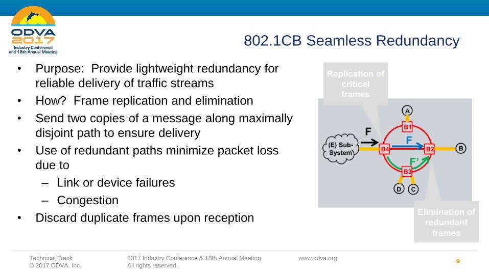
• Purpose: Provide lightweight redundancy for
reliable delivery of traffic streams
• How? Frame replication and elimination
• Send two copies of a message along maximally
disjoint path to ensure delivery
• Use of redundant paths minimize packet loss
due to
– Link or device failures
– Congestion
• Discard duplicate frames upon reception

10
802.1Qci Ingress Policing
Technical Track 2017 Industry Conference & 18th Annual Meeting www.odva.org
© 2017 ODVA, Inc. All rights reserved.
• Purpose: Prevent traffic overload conditions (DDoS, erroneous delivery) from affecting the receiving node
• How? Filtering traffic on a per stream basis by providing an input gate for each stream
• Input gate serves to enforce a "contract" between the talker and listener
• Contract functions could be:– Pass/no-pass
– "Leaky bucket" policing
– Time/bandwidth-based
– Threshold counter
– Burst sizes
– Packet sizes
– Misuse of labels, etc.
11
802.1Qcc - Centralized Configuration
Technical Track 2017 Industry Conference & 18th Annual Meeting www.odva.org
© 2017 ODVA, Inc. All rights reserved.
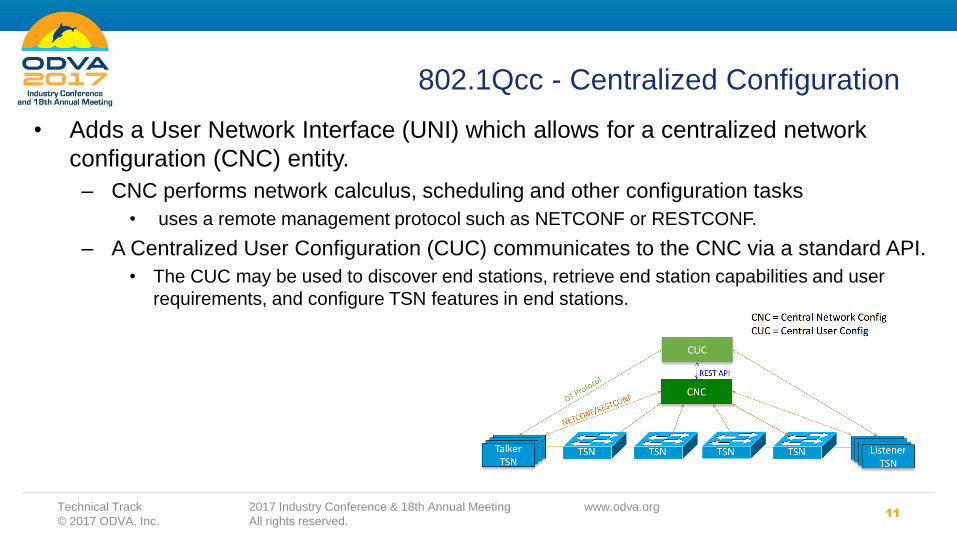
• Adds a User Network Interface (UNI) which allows for a centralized network
configuration (CNC) entity.
– CNC performs network calculus, scheduling and other configuration tasks
• uses a remote management protocol such as NETCONF or RESTCONF.
– A Centralized User Configuration (CUC) communicates to the CNC via a standard API.
• The CUC may be used to discover end stations, retrieve end station capabilities and user
requirements, and configure TSN features in end stations.
12
Industrial Use Case
Technical Track 2017 Industry Conference & 18th Annual Meeting www.odva.org
© 2017 ODVA, Inc. All rights reserved.
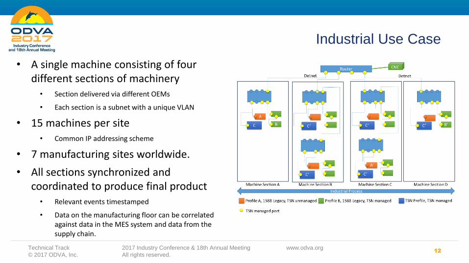
• A single machine consisting of four different sections of machinery
• Section delivered via different OEMs
• Each section is a subnet with a unique VLAN
• 15 machines per site• Common IP addressing scheme
• 7 manufacturing sites worldwide.
• All sections synchronized and coordinated to produce final product
• Relevant events timestamped
• Data on the manufacturing floor can be correlated against data in the MES system and data from the supply chain.

13
Industrial Use Case
Technical Track 2017 Industry Conference & 18th Annual Meeting www.odva.org
© 2017 ODVA, Inc. All rights reserved.
• The entire manufacturing facility uses the same understanding of absolute time and the common notion of “wall clock time.”
• But, different 1588 profiles may be present:
• Component A may communicate with A’
• Component B may communicate with B’
• Component C produces data consumed by C’ components in sections B, C, and D
• Time gateway/translation is required for components A and A’, and B and B’.

14
Time Gateways
Technical Track 2017 Industry Conference & 18th Annual Meeting www.odva.org
© 2017 ODVA, Inc. All rights reserved.
• Time bridging, or time gateway, must be provided in the layer 2 switches
• Provides the mechanism for migrating legacy technologies into a TSN system.
• This functionality has NOT been identified as a required work item for any standards communities. Individual suppliers could develop these bridge functions as solutions for the market.

Challenges
15
• This use case illustrates the need for solutions at layer 2
(switching), layer 3 (routing) and for time bridging functions
• Typical for a very wide range of industrial applications
• How does centralized management deal with such a use case?
• Machine segments are configured and certified by manufacturer
• Multiple CNC/CUCs involved
• How are the configuration and traffic specification of these segments
integrated at the manufacturing site?
• A plant-wide understanding of time becomes problematic
• Integration of different time profiles will be necessary (brownfield)
• IEEE802.1AS could become the defacto standard for infrastructure devices
Technical Track 2017 Industry Conference & 18th Annual Meeting www.odva.org
© 2017 ODVA, Inc. All rights reserved.

16
A Simple Control Model
Technical Track 2017 Industry Conference & 18th Annual Meeting www.odva.org
© 2017 ODVA, Inc. All rights reserved.
• Input data must arrive at Controller before the end of the input interval
• Planned data outputs should be transmitted before the end of the planner interval
• Output data must arrive at the drive before the end of the output interval
• Of course, this all assumes the drives and controller have a common understanding of time.

Models vs. Reality
17
You will never strike oil by drilling through the map!BUT: this does not, in any way, diminish the value of a map! (Solomon Golomb: Mathematical models – Uses and limitations. Aeronautical Journal 1968)
– Source: Dr Edward Lee (UC Berkley) TSNA’15 – The Internet of Important Things
What’s shown is a simple model intended to illustrate the effects of TSN on an Ethernet-based control solution
There are many potential points of optimization in a complex, real-world system. Assumptions made herein are for the purpose of discussion, not to suggest design approaches or solutions.
Technical Track 2017 Industry Conference & 18th Annual Meeting www.odva.org
© 2017 ODVA, Inc. All rights reserved.

18
A Simple Motion Control Model
Technical Track 2017 Industry Conference & 18th Annual Meeting www.odva.org
© 2017 ODVA, Inc. All rights reserved.
• We’ll focus on a part of the problem associated with network performance
• Ideally, we’d like all of the drives to transmit their output data simultaneously
• In this way the link between the controller and bridge is optimally utilized

A Simple Motion Control Model
19
• A simple model for control on a “best-effort” network
• Assumes all network elements are time-aware
• Assumes standard QoS/priority throughout.
• Assume cut-through switch (cut-through latency ~2usec @ 100 Mbs; ~1usec @ 1 Gbs)
– Important for upcoming line topology discussion
• Assumes some control of traffic volume and the size of interfering traffic on the network
Technical Track 2017 Industry Conference & 18th Annual Meeting www.odva.org
© 2017 ODVA, Inc. All rights reserved.

A Simple Motion Control Model
20
– Max Axis = 1 + {1/3 * Connection Update Period – (Drive Transmission Delay + (m + 1) * Ethernet Transmission Time + m * Switch Latency + NIC Packet Processing Delay + Bus Interface Delay)}/NIC Packet Processing Delay
– (Where m = # of hops)
– Drive Transmission Delay: We’ll assume all drives have outputs queued prior to transmission, so this is contribution is small with respect to other operands, effectively 0 usec
– Assume update packets are fairly small(124 bytes), so Ethernet Transmission Time is (124+20)*80ns/byte = 11.52 usec (at 100 Mbs)
– Switch Latency = (interfering packet size+20)*80ns/byte
– NIC Packet Processing Delay – There are techniques to ensure the network is the bottleneck (e.g. 2 cycle processing): 11.5 usec for 100 Mbs, 1.15 for Gigabit..
– Bus Interface Delay: has a lot to do with the overall system architecture. could go effectively to 0 (given good bus structure, DMA/ etc.). We’ll assume 0 for this analysis.
Technical Track 2017 Industry Conference & 18th Annual Meeting www.odva.org
© 2017 ODVA, Inc. All rights reserved.

21
100 Mbs Baseline
Technical Track 2017 Industry Conference & 18th Annual Meeting www.odva.org
© 2017 ODVA, Inc. All rights reserved.
0 5 10 15 20 25
1
2
4
8
Limit Interfering Traffic
Standard Traffic
• Performance strongly influenced by interfering traffic and thus, the number of hops
• In practice, control systems will engineer the network to limit the size of interfering packets (this example assumes 500 bytes)
22
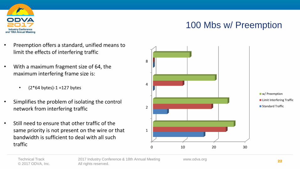
100 Mbs w/ Preemption
Technical Track 2017 Industry Conference & 18th Annual Meeting www.odva.org
© 2017 ODVA, Inc. All rights reserved.
• Preemption offers a standard, unified means to limit the effects of interfering traffic
• With a maximum fragment size of 64, the maximum interfering frame size is:
• (2*64 bytes)-1 =127 bytes
• Simplifies the problem of isolating the control network from interfering traffic
• Still need to ensure that other traffic of the same priority is not present on the wire or that bandwidth is sufficient to deal with all such traffic
0 10 20 30
1
2
4
8
w/ Preemption
Limit Interfering Traffic
Standard Traffic

23
Scheduled Traffic (Qbv)
Technical Track 2017 Industry Conference & 18th Annual Meeting www.odva.org
© 2017 ODVA, Inc. All rights reserved.
…
Controller
Drives
• Utilization of a line topology and scheduled traffic can further minimize effect of interfering traffic
• Schedule of drives can be individually adjusted to compensate for drive transmission delay, transmission time and switch latency.

24
100 Mbs w/ Scheduled Traffic
Technical Track 2017 Industry Conference & 18th Annual Meeting www.odva.org
© 2017 ODVA, Inc. All rights reserved.
• Effects due to switch latency are minimized
• The effects of interfering traffic are of less consideration than the ability of the controller to process incoming packets
• This still assumes a somewhat isolated network (i.e. there is not other traffic of the same class which might interfere with control packets) 0 5 10 15 20 25 30
1
2
4
8
scheduled traffic
w/ Preemption
Limit Interfering Traffic
Standard Traffic
Hops
Axis/mS

25
1 Gbs Results
Technical Track 2017 Industry Conference & 18th Annual Meeting www.odva.org
© 2017 ODVA, Inc. All rights reserved.
• Gigabit transmission speeds further reduce the effects of interfering traffic
• Note that the benefit from scheduled traffic across hops is much less significant

26
1 Gbs Preemption vs Scheduled Traffic
Technical Track 2017 Industry Conference & 18th Annual Meeting www.odva.org
© 2017 ODVA, Inc. All rights reserved.
• Properly engineered, line topology limits the effects of interfering traffic to a single hop (i.e. control traffic is transmitted in a burst)
• With preemption, the effects of interfering traffic are minimal with respect to a 1 mS update cycle
0 5 10 15 20 25 30
100 Mbs
1 Gbs
scheduled traffic
w/ Preemption
Max Axis

27
1 Gbs Preemption vs Scheduled Traffic
Technical Track 2017 Industry Conference & 18th Annual Meeting www.odva.org
© 2017 ODVA, Inc. All rights reserved.
• However, as the update frequency is increased, network effects again become significant.
• Note: this example assumes the network, rather than controller packet processing, is the bottleneck in the system.
0 20 40 60 80
125 uS
250 uS
scheduled traffic
w/ Preemption
Max Axis

28
Control Link: 100 Mbit/sDevice Link: 100 Mbit/s
Control Link: 1 Gbit/s Device Link:100 Mbit/s
Control Link: 1 Gbit/s Device Link:1 Gbit/s
20
40
60
80
100
120
140
160
180
200
220
240
260
240
280
300
320
340
360
380
400
420
440
Nu
mb
er
of
Ax
is
(17)
(35) (37)
(252)
(365)(375)
(411)
(430) (432)
Legend:
No TSN functions enabled
Preemption enabled
Scheduling enabled
Conclusions:
• Wire speed contributes to the
majority of throughput and
performance on the wire.
– Number or axes
– Jitter
• TSN functions allow for better
“packing” of data at any given
wire speed
• There is little difference in
performance benefit between
preemption and scheduling
– However, both can be used
together.
Wire Speed vs. TSN Functionality:
Distributed Linear Segment Topology
Common Configuration
• i7 Processor
• 2-cycle timing
• 1 millisecond motion planner
• 1500 byte non-motion packet
• 1 Switch
• Up to 50 nodes per linear segment
Technical Track 2017 Industry Conference & 18th Annual Meeting www.odva.org
© 2017 ODVA, Inc. All rights reserved.

29
Network Convergence and Centralized Configuration
Technical Track 2017 Industry Conference & 18th Annual Meeting www.odva.org
© 2017 ODVA, Inc. All rights reserved.
• Given these results, do we need scheduled traffic?
• As deployment of Ethernet in Industrial Automation grows more data is desired. Solutions must scale.
• As the Enterprise and Automation networks become more integrated, data flows from various applications must converge.
• IEEE802.1Qcc provides a practical approach for achieving this vision

Summary
30
• TSN technologies offer a scalable, predictable approach to
deterministic networking.
• Because Ethernet/IP products have always relied upon
standardized technologies, ODVA is in an excellent position
to leverage these emerging standards.
• However, significant challenges remain.
• The integration of various PTP profile and the convergence of
EtherNet/IP traffic with a scheduled TSN network are chief
among these challenges.
Technical Track 2017 Industry Conference & 18th Annual Meeting www.odva.org
© 2017 ODVA, Inc. All rights reserved.

THANK YOU