pyroelectric infrared detectors d* up to 1x10 at 10 hz · specific detectivity1,2 >2·108 cm...
TRANSCRIPT

91 Boylston Street, Brookline, MA 02445 Tel: 800-347-5445/617-566-3821 Fax: 617-731-0935 www.Boselec.com [email protected]
Pyroelectric infrared detectors D* up to 1x10⁹ at 10 Hz

HEIMANN Sensor GmbHGrenzstr. 22D-01109 Dresden, Germany
Contact / Customer SupportPhone 49 (0) 6123 60 50 30Fax 49 (0) 6123 60 50 39
Internetwww.heimannsensor.come-mail: [email protected]
Mod
fcatons reserved Rev.01/ 23.08.2010
HPS DUAL CHANNEL PYROELECTRIC Sensor for Gas Analysis
Heimann Sensor thin film pyroelectric gas sensors combine very high responsivity and specific detectivity with low microphonic effect in a small, TO-5 type package. Various different narrow band filters can adapt the sensor to a wide variety of different environmental gases. Using a compensation channel, the sensor can be made insensitive to both ambient temperature and long term drift effects. On request our application team will offer you a suitable IR radiation source for your special gas application.
Gnd
Ch1
Ch2
V+
Recommended Circuit

� � � � �
� � � �
� �� � � � � � �
� � � � � � �
� � �
� � � � � � � �
�
� � �
� � �
� � �
� � �
� � �
������������������
� � � � � � � � ! " # � $
% � ��
� � � � # �
" % &�$
' � " � ( � � # � $
��
) � � �
*�
� � *� � �
� � � � � � � � �
) � �
��
� � � � � �
� � � � � � �
��
��
�+)
� � � � � �
� � � � � � �
, � � � � � � � � �
HPS A01B Pyroelectric Single Element Detector forMeasurement Applications
element size 1 mm × 1 mm
aperture 5.0 mm
filter3
custom-designed
responsivity1,2
>1100 V/W
noise1
<500 nV/�Hz
specific detectivity1,2
>2·108 cm
�Hz / W
offset voltage 0.4 to 1.5 V
operating voltage 2 to 18 V
housing TO 39
operating temperature –20 to 70 °C
storage temperature –20 to 70 °C
1) frequency: 10 Hz, detector temperature: 25 °C2) black body source temperature: 500 K, filter transmission: 100 %3) other filters on request
Boston Electronics Corporation 91 Boylston Street, Brookline MA 02445 USAphone: +1 (800) 347-5445 or +1 (617) 566-3821 fax: +1 (617) 731-0935e-mail: [email protected] www. boselec.com
101
102
103
104
105
100 101 102 103
resp
onsi
vity
(V/W
)
frequency (Hz)
100
101
102
103
104
100 101 102 103
nois
e (n
V/√
Hz)
frequency (Hz)
106
107
108
109
1010
100 101 102 103
spec
ific
dete
ctiv
ity (c
m√H
z/W
)
frequency (Hz)
Fu
rth
er
de
ve
lop
me
nts
ma
y e
nta
il m
od
ific
atio
ns o
f in
dic
ate
d d
ata
witho
ut
notificatio
n R
evis
ion
01
/20
07
12
01
20
07 b
ose
lec_
hp
sa
01
b_
en
g

� � � � �
� � � �
� �� � � � � � �
� � � � � � �
� � �
� � � � � � � �
�
� � �
� � �
� � �
� � �
� � �
������������������
� � � � � � � � ! " # � $
% � ��
� � � � # �
" % &�$
' � " � ( � � # � $
��
) � � �
*�
� � *� � �
� � � � � � � � �
) � �
��
� � � � � �
� � � � � � �
��
��
�+)
� � � � � �
� � � � � � �
, � � � � � � � � �
HPS A01E Pyroelectric Single Element Detector forMeasurement Applications
element size 2 mm × 2 mm
aperture 5.0 mm
filter3
custom-designed
responsivity1,2
>300 V/W
noise1
<150 nV/�Hz
specific detectivity1,2
>4·108 cm
�Hz / W
offset voltage 0.4 to 1.5 V
operating voltage 2 to 18 V
housing TO 39
operating temperature –20 to 70 °C
storage temperature –20 to 70 °C
1) frequency: 10 Hz, detector temperature: 25 °C2) black body source temperature: 500 K, filter transmission: 100 %3) other filters on request
Boston Electronics Corporation 91 Boylston Street, Brookline MA 02445 USAphone: +1 (800) 347-5445 or +1 (617) 566-3821 fax: +1 (617) 731-0935e-mail: [email protected] www. boselec.com
100
101
102
103
104
100 101 102 103
resp
onsi
vity
(V/W
)
frequency (Hz)
100
101
102
103
104
100 101 102 103
nois
e (n
V/√
Hz)
frequency (Hz)
106
107
108
109
1010
100 101 102 103
spec
ific
dete
ctiv
ity (c
m√H
z/W
)
frequency (Hz)
Fu
rth
er
de
ve
lop
me
nts
ma
y e
nta
il m
od
ific
atio
ns o
f in
dic
ate
d d
ata
witho
ut
notificatio
n R
evis
ion
01
/20
07
12
01
20
07 b
ose
lec_
hp
sa
01
e_
en
g

� � � � �
� � � �
� �� � � � � � �
� � � � � � �
� � �
� � � � � � � �
�
� � �
� � �
� � �
� � �
� � �
������������������
� � � � � � � � ! " # � $
% � ��
� � � � # �
" % &�$
' � " � ( � � # � $
��
) � � �
*�
� � *� � �
� � � � � � � � �
) � �
��
� � � � � �
� � � � � � �
��
��
�+)
� � � � � �
� � � � � � �
, � � � � � � � � �
HPS A02A Pyroelectric Single Element Detector forMeasurement Applications
element size 0.5 mm × 0.5 mm
aperture 5.0 mm
filter3
custom-designed
responsivity1,2
>3500 V/W
noise1
<500 nV/�Hz
specific detectivity1,2
>3·108 cm
�Hz / W
offset voltage 0.4 to 1.5 V
operating voltage 2 to 18 V
housing TO 39
operating temperature –20 to 70 °C
storage temperature –20 to 70 °C
1) frequency: 10 Hz, detector temperature: 25 °C2) black body source temperature: 500 K, filter transmission: 100 %3) other filters on request
Boston Electronics Corporation 91 Boylston Street, Brookline MA 02445 USAphone: +1 (800) 347-5445 or +1 (617) 566-3821 fax: +1 (617) 731-0935e-mail: [email protected] www. boselec.com
101
102
103
104
105
100 101 102 103
resp
onsi
vity
(V/W
)
frequency (Hz)
100
101
102
103
104
100 101 102 103
nois
e (n
V/√
Hz)
frequency (Hz)
106
107
108
109
1010
100 101 102 103
spec
ific
dete
ctiv
ity (c
m√H
z/W
)
frequency (Hz)
Fu
rth
er
de
ve
lop
me
nts
ma
y e
nta
il m
od
ific
atio
ns o
f in
dic
ate
d d
ata
witho
ut
notificatio
n R
evis
ion
01
/20
07
12
01
20
07 b
ose
lec_
hp
sa
02
a_
en
g

� � � � �
� � � �
� �� � � � � � �
� � � � � � �
� � �
� � � � � � � �
�
� � �
� � �
� � �
� � �
� � �
������������������
� � � � � � � � ! " # � $
% � ��
� � � � # �
" % &�$
' � " � ( � � # � $
��
) � � �
*�
� � *� � �
� � � � � � � � �
) � �
��
� � � � � �
� � � � � � �
��
��
�+)
� � � � � �
� � � � � � �
, � � � � � � � � �
HPS A02B Pyroelectric Single Element Detector forMeasurement Applications
element size 1 mm × 1 mm
aperture 5.0 mm
filter3
custom-designed
responsivity1,2
>900 V/W
noise1
<160 nV/�Hz
specific detectivity1,2
>6·108 cm
�Hz / W
offset voltage 0.4 to 1.5 V
operating voltage 2 to 18 V
housing TO 39
operating temperature –20 to 70 °C
storage temperature –20 to 70 °C
1) frequency: 10 Hz, detector temperature: 25 °C2) black body source temperature: 500 K, filter transmission: 100 %3) other filters on request
Boston Electronics Corporation 91 Boylston Street, Brookline MA 02445 USAphone: +1 (800) 347-5445 or +1 (617) 566-3821 fax: +1 (617) 731-0935e-mail: [email protected] www. boselec.com
100
101
102
103
104
100 101 102 103
resp
onsi
vity
(V/W
)
frequency (Hz)
100
101
102
103
104
100 101 102 103
nois
e (n
V/√
Hz)
frequency (Hz)
106
107
108
109
1010
100 101 102 103
spec
ific
dete
ctiv
ity (c
m√H
z/W
)
frequency (Hz)
Fu
rth
er
de
ve
lop
me
nts
ma
y e
nta
il m
od
ific
atio
ns o
f in
dic
ate
d d
ata
witho
ut
notificatio
n R
evis
ion
01
/20
07
12
01
20
07 b
ose
lec_
hp
sa
02
b_
en
g

� � � � �
� � � �
� �� � � � � � �
� � � � � � �
� � �
� � � � � � � �
�
� � �
� � �
� � �
� � �
� � �
������������������
� � � � � � � � ! " # � $
% � ��
� � � � # �
" % &�$
' � " � ( � � # � $
��
) � � �
*�
� � *� � �
� � � � � � � � �
) � �
��
� � � � � �
� � � � � � �
��
��
�+)
� � � � � �
� � � � � � �
, � � � � � � � � �
HPS A02E Pyroelectric Single Element Detector forMeasurement Applications
element size 2 mm × 2 mm
aperture 5.0 mm
filter3
custom-designed
responsivity1,2
>250 V/W
noise1
<80 nV/�Hz
specific detectivity1,2
>8·108 cm
�Hz / W
offset voltage 0.4 to 1.5 V
operating voltage 2 to 18 V
housing TO 39
operating temperature –20 to 70 °C
storage temperature –20 to 70 °C
1) frequency: 10 Hz, detector temperature: 25 °C2) black body source temperature: 500 K, filter transmission: 100 %3) other filters on request
Boston Electronics Corporation 91 Boylston Street, Brookline MA 02445 USAphone: +1 (800) 347-5445 or +1 (617) 566-3821 fax: +1 (617) 731-0935e-mail: [email protected] www. boselec.com
100
101
102
103
104
100 101 102 103
resp
onsi
vity
(V/W
)
frequency (Hz)
100
101
102
103
104
100 101 102 103
nois
e (n
V/√
Hz)
frequency (Hz)
106
107
108
109
1010
100 101 102 103
spec
ific
dete
ctiv
ity (c
m√H
z/W
)
frequency (Hz)
Fu
rth
er
de
ve
lop
me
nts
ma
y e
nta
il m
od
ific
atio
ns o
f in
dic
ate
d d
ata
witho
ut
notificatio
n R
evis
ion
01
/20
07
12
01
20
07 b
ose
lec_
hp
sa
02
e_
en
g

� � � � �
� � � �
� �� � � � � � �
� � � � � � �
� � �
� � � � � � � �
�
� � �
� � �
� � �
� � �
� � �
������������������
� � � � � � � � ! " # � $
% � ��
� � � � # �
" % &�$
' � " � ( � � # � $
��
) � � �
*�
� � *� � �
� � � � � � � � �
) � �
��
� � � � � �
� � � � � � �
��
��
�+)
� � � � � �
� � � � � � �
, � � � � � � � � �
HPS A03E Pyroelectric Single Element Detector forMeasurement Applications
element size 2 mm × 2 mm
aperture 5.0 mm
filter3
custom-designed
responsivity1,2
>420 V/W
noise1
<150 nV/�Hz
specific detectivity1,2
>5·108 cm
�Hz / W
offset voltage 0.4 to 1.5 V
operating voltage 2 to 18 V
housing TO 39
operating temperature –20 to 60 °C
storage temperature –20 to 60 °C
1) frequency: 10 Hz, detector temperature: 25 °C2) black body source temperature: 500 K, filter transmission: 100 %3) other filters on request
Boston Electronics Corporation 91 Boylston Street, Brookline MA 02445 USAphone: +1 (800) 347-5445 or +1 (617) 566-3821 fax: +1 (617) 731-0935e-mail: [email protected] www. boselec.com
100
101
102
103
104
100 101 102 103
resp
onsi
vity
(V/W
)
frequency (Hz)
100
101
102
103
104
100 101 102 103
nois
e (n
V/√
Hz)
frequency (Hz)
106
107
108
109
1010
100 101 102 103
spec
ific
dete
ctiv
ity (c
m√H
z/W
)
frequency (Hz)
Fu
rth
er
de
ve
lop
me
nts
ma
y e
nta
il m
od
ific
atio
ns o
f in
dic
ate
d d
ata
witho
ut
notificatio
n R
evis
ion
01
/20
07
12
01
20
07 b
ose
lec_
hp
sa
03
e_
en
g

� � � � �
� � � �
� �� � � � � � �
� � � � � � �
� � �
� � � � � � � �
�
� � �
� � �
� � �
� � �
� � �
������������������
� � � � � � � � ! " # � $
% � ��
� � � � # �
" % &�$
' � " � ( � � # � $
��
) � � �
*�
� � *� � �
� � � � � � � � �
) � �
��
� � � � � �
� � � � � � �
��
��
�+)
� � � � � �
� � � � � � �
, � � � � � � � � �
HPS A04E Pyroelectric Single Element Detector forMeasurement Applications
element size 2 mm × 2 mm
aperture 5.0 mm
filter3
custom-designed
responsivity1,2
>350 V/W
noise1
<80 nV/�Hz
specific detectivity1,2
>9·108 cm
�Hz / W
offset voltage 0.4 to 1.5 V
operating voltage 2 to 18 V
housing TO 39
operating temperature –20 to 60 °C
storage temperature –20 to 60 °C
1) frequency: 10 Hz, detector temperature: 25 °C2) black body source temperature: 500 K, filter transmission: 100 %3) other filters on request
Boston Electronics Corporation 91 Boylston Street, Brookline MA 02445 USAphone: +1 (800) 347-5445 or +1 (617) 566-3821 fax: +1 (617) 731-0935e-mail: [email protected] www. boselec.com
100
101
102
103
104
100 101 102 103
resp
onsi
vity
(V/W
)
frequency (Hz)
100
101
102
103
104
100 101 102 103
nois
e (n
V/√
Hz)
frequency (Hz)
106
107
108
109
1010
100 101 102 103
spec
ific
dete
ctiv
ity (c
m√H
z/W
)
frequency (Hz)
Fu
rth
er
de
ve
lop
me
nts
ma
y e
nta
il m
od
ific
atio
ns o
f in
dic
ate
d d
ata
witho
ut
notificatio
n R
evis
ion
01
/20
07
12
01
20
07 b
ose
lec_
hp
sa
04
e_
en
g

� � � � �
� � � �
� �� � � � � � �
� � � � � � �
� � �
� � � � � � � �
�
� � �
� � �
� � �
� � �
� � �
������������������
� � � � � � � � ! " # � $
% � ��
� � � � # �
" % &�$
' � " � ( � � # � $
��
) � � �
*�
� � *� � �
� � � � � � � � �
) � �
��
� � � � � �
� � � � � � �
��
��
�+)
� � � � � �
� � � � � � �
, � � � � � � � � �
HPS A04G Pyroelectric Single Element Detector forMeasurement Applications
element size 3 mm × 3 mm
aperture 5.0 mm
filter3
custom-designed
responsivity1,2
>180 V/W
noise1
<60 nV/�Hz
specific detectivity1,2
>10·108 cm
�Hz / W
offset voltage 0.4 to 1.5 V
operating voltage 2 to 18 V
housing TO 39
operating temperature –20 to 60 °C
storage temperature –20 to 60 °C
1) frequency: 10 Hz, detector temperature: 25 °C2) black body source temperature: 500 K, filter transmission: 100 %3) other filters on request
Boston Electronics Corporation 91 Boylston Street, Brookline MA 02445 USAphone: +1 (800) 347-5445 or +1 (617) 566-3821 fax: +1 (617) 731-0935e-mail: [email protected] www. boselec.com
100
101
102
103
104
100 101 102 103
resp
onsi
vity
(V/W
)
frequency (Hz)
100
101
102
103
104
100 101 102 103
nois
e (n
V/√
Hz)
frequency (Hz)
106
107
108
109
1010
100 101 102 103
spec
ific
dete
ctiv
ity (c
m√H
z/W
)
frequency (Hz)
Fu
rth
er
de
ve
lop
me
nts
ma
y e
nta
il m
od
ific
atio
ns o
f in
dic
ate
d d
ata
witho
ut
notificatio
n R
evis
ion
01
/20
07
12
01
20
07 b
ose
lec_
hp
sa
04
g_
en
g

� � � � �
� � � �
� �� � � � � � �
� � � � � � �
� � �
� � � � � � � �
�
� � �
� � �
� � �
� � �
� � �
������������������
� � � � � � � � ! " # � $
% � ��
� � � � # �
" % &�$
' � " � ( � � # � $
��
) � � �
*�
� � *� � �
� � � � � � � � �
) � �
��
� � � � � �
� � � � � � �
��
��
�+)
� � � � � �
� � � � � � �
, � � � � � � � � �
HPS A05F Pyroelectric Single Element Detector forMeasurement Applications
element size ���2.5 mm
aperture 5.0 mm
filter3
custom-designed
responsivity1,2
>220 V/W
noise1
<140 nV/�Hz
specific detectivity1,2
>4·108 cm
�Hz / W
offset voltage 0.4 to 1.5 V
operating voltage 2 to 18 V
housing TO 39
operating temperature –20 to 70 °C
storage temperature –20 to 70 °C
1) frequency: 10 Hz, detector temperature: 25 °C2) black body source temperature: 500 K, filter transmission: 100 %3) other filters on request
Boston Electronics Corporation 91 Boylston Street, Brookline MA 02445 USAphone: +1 (800) 347-5445 or +1 (617) 566-3821 fax: +1 (617) 731-0935e-mail: [email protected] www. boselec.com
100
101
102
103
104
100 101 102 103
resp
onsi
vity
(V/W
)
frequency (Hz)
100
101
102
103
104
100 101 102 103
nois
e (n
V/√
Hz)
frequency (Hz)
106
107
108
109
1010
100 101 102 103
spec
ific
dete
ctiv
ity (c
m√H
z/W
)
frequency (Hz)
Fu
rth
er
de
ve
lop
me
nts
ma
y e
nta
il m
od
ific
atio
ns o
f in
dic
ate
d d
ata
witho
ut
notificatio
n R
evis
ion
01
/20
07
12012007 b
osele
c_hpsa05f_
eng
� � � � �
� � � � �
� � �
� � � �
� � �
� � � � � � � �
� � � � � � � � �
� � � � � � �
� � � � � � � �
�
� �
� � � � � �
� � � � � �
� � �
� � �
� � �
� � �
� � �
�������������������
� � � � � � ! � " � # $ � %
& � ��
� � � � � $ �
# & '�%
( � � # � ) � � $ � %
��
* � � �
+�
� � +� � � � � �
� � � � � � � � � �
� � �
�
� � � � � � � � �
� � � � � � � �
��
�*
�*
,*
� � � � � �
� � � � � � �
- � � � � � � � � �
� � �
��
� � � � � �
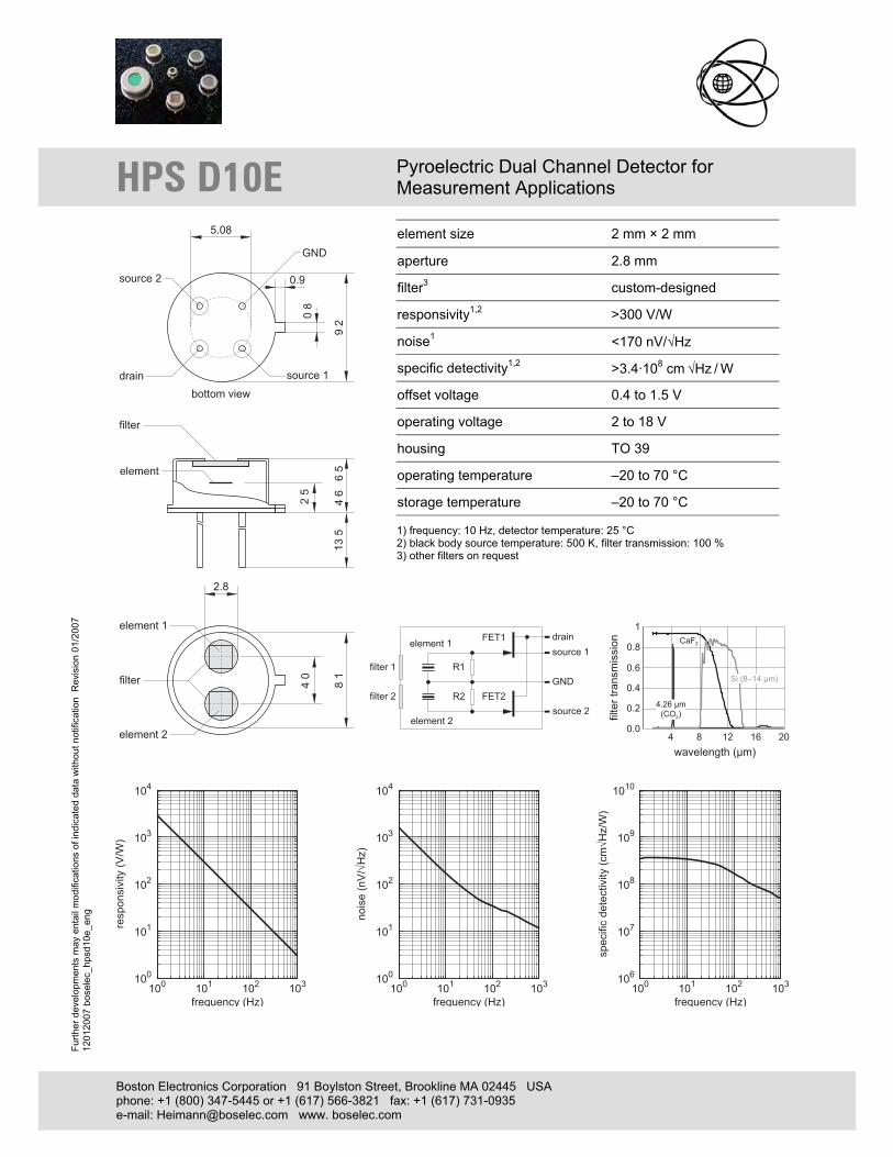
HPS D10E Pyroelectric Dual Channel Detector forMeasurement Applications
element size 2 mm × 2 mm
aperture 2.8 mm
filter3
custom-designed
responsivity1,2
>300 V/W
noise1
<170 nV/�Hz
specific detectivity1,2
>3.4·108 cm
�Hz / W
offset voltage 0.4 to 1.5 V
operating voltage 2 to 18 V
housing TO 39
operating temperature –20 to 70 °C
storage temperature –20 to 70 °C
1) frequency: 10 Hz, detector temperature: 25 °C2) black body source temperature: 500 K, filter transmission: 100 %3) other filters on request
Boston Electronics Corporation 91 Boylston Street, Brookline MA 02445 USAphone: +1 (800) 347-5445 or +1 (617) 566-3821 fax: +1 (617) 731-0935e-mail: [email protected] www. boselec.com
100
101
102
103
104
100 101 102 103
resp
onsi
vity
(V/W
)
frequency (Hz)
100
101
102
103
104
100 101 102 103
nois
e (n
V/√
Hz)
frequency (Hz)
106
107
108
109
1010
100 101 102 103
spec
ific
dete
ctiv
ity (c
m√H
z/W
)
frequency (Hz)
Fu
rth
er
de
ve
lop
me
nts
ma
y e
nta
il m
od
ific
atio
ns o
f in
dic
ate
d d
ata
witho
ut
notificatio
n R
evis
ion
01
/20
07
12
01
20
07 b
ose
lec_
hp
sd
10
e_
en
g

�� �
�
�
���������
���
���������
����
� � � �
� � � � � �
� � � � � � � � �
��
� � � �
����
� � �
� � � � � � � �
� � � � � � �
� � � � � � � �
� � �
� � � � � � �
� � � � �
� � � � � � � �
� � �
� ! �
� ! �
� � � � � � � �
� � � � � � � �
� � � � � �
� � � � � �
" �
" �
� � � � � � � �
� # � � � � � �
�
� � �
� � �
� � �
� � �
� � #
�� ��� �����������
� � � � � � � $ % � & ' � (
) � ��
� � � � � ' �
& ) *�(
+ � � & # , � � � ' � (
HPS DS10E Pyroelectric Dual Channel Detector forMeasurement Applications
element size 2 mm × 2 mm
aperture 3.0 mm
filter3 custom-designed
responsivity1,2 >300 V/W
noise1 <170 nV/�Hz
specific detectivity1,2 >3.4·108 cm �Hz / W
offset voltage 0.4 to 1.5 V
operating voltage 2 V to 18 V
housing TO 8
operating temperature –20 to 70 °C
storage temperature –20 to 70 °C
1) frequency: 10 Hz, detector temperature: 25 °C 2) black body source temperature: 500 K, filter transmission: 100 % 3) other filters on request
HEIMANN Sensor GmbH Contact / Customer Support InternetGrenzstr. 22 Phone 49 (0) 6123 60 50 30 www.heimannsensor.com D-01109 Dresden Fax 49 (0) 6123 60 50 39 e-mail: [email protected]
100
101
102
103
104
100 101 102 103
resp
onsi
vity
(V/W
)
frequency (Hz)
100
101
102
103
104
100 101 102 103
nois
e (n
V/√
Hz)
frequency (Hz)
106
107
108
109
1010
100 101 102 103
spec
ific
dete
ctiv
ity (c
m√H
z/W
)
frequency (Hz)
Furth
er d
evel
opm
ents
may
ent
ail m
odifi
catio
ns o
f ind
icat
ed d
ata
with
out n
otifi
catio
n R
evis
ion
05/2
011
31
0520
11 h
psds
10e_
eng

�� �
�
�
���������
���
���������
����
� � � �
� � � � � �
� � � � � � � � �
���
� � � �
����
� � �
� � � � � � � �
� � � � � � �
� � � � � � � �
� � �
� � � � � � �
� � � � �
� � � � � � � �
� � �
� ! �
� ! �
� � � � � � � �
� � � � � � � �
� � � � � �
� � � � � �
" �
" �
� � � � � � � �
� # � � � � � �
�
� � �
� � �
� � �
� � �
� � #
�� ��� �����������
� � � � � � � $ % � & ' � (
) � ��
� � � � � ' �
& ) *�(
+ � � & # , � � � ' � (
HPS D30E Pyroelectric Dual Channel Detector forMeasurement Applications
element size 2 mm × 2 mm
aperture 4.0 mm
filter3
custom-designed
responsivity1,2
>150 V/W
noise1
<100 nV/�Hz
specific detectivity1,2
>3·108 cm
�Hz / W
thermal compensation parallel
offset voltage 0.4 to 1.5 V
operating voltage 2 to 18 V
housing TO 8
operating temperature –20 to 70 °C
storage temperature –20 to 70 °C
1) frequency: 10 Hz, detector temperature: 25 °C2) black body source temperature: 500 K, filter transmission: 100 %3) other filters on request
100
101
102
103
104
100 101 102 103
resp
onsi
vity
(V/W
)
frequency (Hz)
100
101
102
103
104
100 101 102 103
nois
e (n
V/√
Hz)
frequency (Hz)
106
107
108
109
1010
100 101 102 103
spec
ific
dete
ctiv
ity (c
m√H
z/W
)
frequency (Hz)
Fu
rth
er
de
ve
lop
me
nts
ma
y e
nta
il m
od
ific
atio
ns o
f in
dic
ate
d d
ata
witho
ut
notificatio
n R
evis
ion
01
/20
07
12
01
20
07 b
ose
lec_
hp
sd
30
e_
en
g
Boston Electronics Corporation 91 Boylston Street, Brookline MA 02445 USAphone: +1 (800) 347-5445 or +1 (617) 566-3821 fax: +1 (617) 731-0935e-mail: [email protected] www. boselec.com

� � � � �
� � � �
� �� � � � � � �
� � � � � � �
� � �
� � � � � � � �
�
� � �
� � �
� � �
� � �
� � �
������������������
� � � � � � � � ! " # � $
% � ��
� � � � # �
" % &�$
' � " � ( � � # � $
��
) � � �
*�
� � *� � �
� � � � � � � � �
) � �
��
� � � � � �
� � � � � � �
��
�)
�)
�+)
� � � � � �
� � � � � � �
, � � � � � � � � �
HPS E09E Pyroelectric Single Element Detector forMeasurement Applications
element size 2 mm × 2 mm
aperture 5.0 mm
filter3
custom-designed
responsivity1,2
>300 V/W
noise1
<170 nV/�Hz
specific detectivity1,2
>3.5·108 cm
�Hz / W
offset voltage 0.4 to 1.5 V
operating voltage 2 to 18 V
housing TO 39
operating temperature –20 to 70 °C
storage temperature –20 to 70 °C
1) frequency: 10 Hz, detector temperature: 25 °C2) black body source temperature: 500 K, filter transmission: 100 %3) other filters on request
Boston Electronics Corporation 91 Boylston Street, Brookline MA 02445 USAphone: +1 (800) 347-5445 or +1 (617) 566-3821 fax: +1 (617) 731-0935e-mail: [email protected] www. boselec.com
100
101
102
103
104
100 101 102 103
resp
onsi
vity
(V/W
)
frequency (Hz)
100
101
102
103
104
100 101 102 103
nois
e (n
V/√
Hz)
frequency (Hz)
106
107
108
109
1010
100 101 102 103
spec
ific
dete
ctiv
ity (c
m√H
z/W
)
frequency (Hz)
Fu
rth
er
de
ve
lop
me
nts
ma
y e
nta
il m
od
ific
atio
ns o
f in
dic
ate
d d
ata
witho
ut
notificatio
n R
evis
ion
01
/20
07
12
01
20
07 b
ose
lec_
hp
se
09
e_
en
g

� � � � �
� � � �
� �� � � � � � �
� � � � � � �
� � �
� � � � � � � �
�
� � �
� � �
� � �
� � �
� � �
������������������
� � � � � � � � ! " # � $
% � ��
� � � � # �
" % &�$
' � " � ( � � # � $
��
) � � �
*�
� � *� � �
� � � � � � � � �
) � �
��
� � � � � �
� � � � � � �
��
�)
�)
�+)
� � � � � �
� � � � � � �
, � � � � � � � � �
HPS E10E Pyroelectric Single Element Detector forMeasurement Applications
element size 2 mm × 2 mm
aperture 5.0 mm
filter3
custom-designed
responsivity1,2
>400 V/W
noise1
<170 nV/�Hz
specific detectivity1,2
>4.5·108 cm
�Hz / W
offset voltage 0.4 to 1.5 V
operating voltage 2 to 18 V
housing TO 39
operating temperature –20 to 70 °C
storage temperature –20 to 70 °C
1) frequency: 10 Hz, detector temperature: 25 °C2) black body source temperature: 500 K, filter transmission: 100 %3) other filters on request
Boston Electronics Corporation 91 Boylston Street, Brookline MA 02445 USAphone: +1 (800) 347-5445 or +1 (617) 566-3821 fax: +1 (617) 731-0935e-mail: [email protected] www. boselec.com
100
101
102
103
104
100 101 102 103
resp
onsi
vity
(V/W
)
frequency (Hz)
100
101
102
103
104
100 101 102 103
nois
e (n
V/√
Hz)
frequency (Hz)
106
107
108
109
1010
100 101 102 103
spec
ific
dete
ctiv
ity (c
m√H
z/W
)
frequency (Hz)
Fu
rth
er
de
ve
lop
me
nts
ma
y e
nta
il m
od
ific
atio
ns o
f in
dic
ate
d d
ata
witho
ut
notificatio
n R
evis
ion
01
/20
07
12
01
20
07 b
ose
lec_
hp
se
10
e_
en
g

� � � � �
� � � �
� �� � � � � � �
� � � � � � �
� � �
� � � � � � � �
�
� � �
� � �
� � �
� � �
� � �
������������������
� � � � � � � � ! " # � $
% � ��
� � � � # �
" % &�$
' � " � ( � � # � $
��
) � � �
*�
� � *� � �
� � � � � � � � �
) � �
��
� � � � � �
� � � � � � �
��
�)
�)
�+)
� � � � � �
� � � � � � �
, � � � � � � � � �
HPS E29E Pyroelectric Single Element Detector forMeasurement Applications
element size 2 mm × 2 mm
aperture 5.0 mm
filter3
custom-designed
responsivity1,2
>200 V/W
noise1
<100 nV/�Hz
specific detectivity1,2
>3.7·108 cm
�Hz / W
thermal compensation parallel
offset voltage 0.4 to 1.5 V
operating voltage 2 to 18 V
housing TO 39
operating temperature –20 to 70 °C
storage temperature –20 to 70 °C
1) frequency: 10 Hz, detector temperature: 25 °C2) black body source temperature: 500 K, filter transmission: 100 %3) other filters on request
100
101
102
103
104
100 101 102 103
resp
onsi
vity
(V/W
)
frequency (Hz)
100
101
102
103
104
100 101 102 103
nois
e (n
V/√
Hz)
frequency (Hz)
106
107
108
109
1010
100 101 102 103
spec
ific
dete
ctiv
ity (c
m√H
z/W
)
frequency (Hz)
Fu
rth
er
de
ve
lop
me
nts
ma
y e
nta
il m
od
ific
atio
ns o
f in
dic
ate
d d
ata
witho
ut
notificatio
n R
evis
ion
01
/20
07
12
01
20
07 b
ose
lec_
hp
se
29
e_
en
g
Boston Electronics Corporation 91 Boylston Street, Brookline MA 02445 USAphone: +1 (800) 347-5445 or +1 (617) 566-3821 fax: +1 (617) 731-0935e-mail: [email protected] www. boselec.com

� � � � �
� � � �
� �� � � � � � �
� � � � � � �
� � �
� � � � � � � �
�
� � �
� � �
� � �
� � �
� � �
������������������
� � � � � � � � ! " # � $
% � ��
� � � � # �
" % &�$
' � " � ( � � # � $
��
) � � �
*�
� � *� � �
� � � � � � � � �
) � �
��
� � � � � �
� � � � � � �
��
�)
�)
�+)
� � � � � �
� � � � � � �
, � � � � � � � � �
HPS E30E Pyroelectric Single Element Detector forMeasurement Applications
element size 2 mm × 2 mm
aperture 5.0 mm
filter3 custom-designed
responsivity1,2 >150 V/W
noise1 <100 nV��Hz
specific detectivity1,2 >3·108 cm �Hz / W
thermal compensation parallel
offset voltage 0.4 to 1.5 V
operating voltage 2 to 18 V
housing TO 39
operating temperature –20 to 70 °C
storage temperature –20 to 70 °C
1) frequency: 10 Hz, detector temperature: 25 °C 2) black body source temperature: 500 K, filter transmission: 100 % 3) other filters on request
Heimann Sensor GmbH Grenzstr. 22 D-01109 Dresden Germany www.heimannsensor.com Contact / Customer service: phone: +49 (6123) 605030 fax: +49 (6123) 605039 e-mail: [email protected]
100
101
102
103
104
100 101 102 103
resp
onsi
vity
(V/W
)
frequency (Hz)
100
101
102
103
104
100 101 102 103
nois
e (n
V/�
Hz)
frequency (Hz)
106
107
108
109
1010
100 101 102 103
spec
ific
dete
ctiv
ity (c
m�H
z/W
)
frequency (Hz)
Furth
er d
evel
opm
ents
may
ent
ail m
odifi
catio
ns o
f ind
icat
ed d
ata
with
out n
otifi
catio
n R
evis
ion
10/2
008
06
1020
08
hps
e30
3_en
g

��
� � ) �
)�
� � *� � �
� � � �
� � � � �
+ � �
�-
� � � � � �
� � � � � � �
+-
)�
��
�+)
� � � � � �
� � � � � � �
, � � � � � � � � �
� � �
� � � � �
� � � �
� �� � � � � � �
� � � � � � �
� � �
� � � � � � � �
�
� � �
� � �
� � �
� � �
� � �
������������������
� � � � � � � � ! " # � $
% � ��
� � � � # �
" % &�$
' � " � ( � � # � $
HPS K09C Pyroelectric Single Element Detector forMeasurement Applications
element size 1.2 mm × 1.2 mm
aperture 3.0 mm
filter3
custom-designed
responsivity1,2
>730 V/W
noise1
<370 nV/�Hz
specific detectivity1,2
>2.3·108 cm
�Hz / W
offset voltage 0.4 to 1.5 V
operating voltage 2 to 18 V
housing TO 18
operating temperature –20 to 70 °C
storage temperature –20 to 70 °C
1) frequency: 10 Hz, detector temperature: 25 °C2) black body source temperature: 500 K, filter transmission: 100 %3) other filters on request
Boston Electronics Corporation 91 Boylston Street, Brookline MA 02445 USAphone: +1 (800) 347-5445 or +1 (617) 566-3821 fax: +1 (617) 731-0935e-mail: [email protected] www. boselec.com
100
101
102
103
104
100 101 102 103
resp
onsi
vity
(V/W
)
frequency (Hz)
100
101
102
103
104
100 101 102 103
nois
e (n
V/√
Hz)
frequency (Hz)
106
107
108
109
1010
100 101 102 103
spec
ific
dete
ctiv
ity (c
m√H
z/W
)
frequency (Hz)
Fu
rth
er
de
ve
lop
me
nts
ma
y e
nta
il m
od
ific
atio
ns o
f in
dic
ate
d d
ata
witho
ut
notificatio
n R
evis
ion
01
/20
07
12
01
20
07 b
ose
lec_
hp
sk0
9c_
en
g

���
� � � �
���
� � � � �
� � � �
� � � �
� � �
���
� � � � � �
� � � � � �
���������
���
����
� � � � � �
� � � � � �
� � � � � � � � � �
� � �
� � � �
� � � �
� !� � � � � �
� � � � � � "
� � �
� # � � � $ � �
�
� � �
� � �
� � �
� � $
� � #
����������������
� � � � � � % � & ' ( � )
* � ��
� � � $ ( �
' * +�)
, � ' # - � � ( � )
HPS K10C Pyroelectric Single Element Detector forMeasurement Applications
element size 1.2 mm × 1.2 mm
aperture 3.0 mm
filter3
custom-designed
responsivity1,2
>900 V/W
noise1
<370 nV/�Hz
specific detectivity1,2
>3·108 cm
�Hz / W
offset voltage 0.4 to 1.5 V
operating voltage 2 to 18 V
housing TO 18
operating temperature –20 to 70 °C
storage temperature –20 to 70 °C
1) frequency: 10 Hz, detector temperature: 25 °C2) black body source temperature: 500 K, filter transmission: 100 %3) other filters on request
Boston Electronics Corporation 91 Boylston Street, Brookline MA 02445 USAphone: +1 (800) 347-5445 or +1 (617) 566-3821 fax: +1 (617) 731-0935e-mail: [email protected] www. boselec.com
100
101
102
103
104
100 101 102 103
resp
onsi
vity
(V/W
)
frequency (Hz)
100
101
102
103
104
100 101 102 103
nois
e (n
V/√
Hz)
frequency (Hz)
105
106
107
108
109
100 101 102 103
spec
ific
dete
ctiv
ity (c
m√H
z/W
)
frequency (Hz)
Fu
rth
er
de
ve
lop
me
nts
ma
y e
nta
il m
od
ific
atio
ns o
f in
dic
ate
d d
ata
witho
ut
notificatio
n R
evis
ion
01
/20
07
12
01
20
07 b
ose
lec_
hp
sk1
0c_
en
g

����
�� �
��
� �
��������
��
��������
� �
� � � � � � �
� � � � � � �
� � � � � � �
� �
� � � � � � �
���
� � � � � �
� � � � � � �
� � � � � � � � � � �
� � � � � � � � � � � � � � � �
� � � � � � � � � � � � � � � �
���
� � �
� � � � � � �
� ! �
� � � � � � � � �
� � � � � � � �
" �
� � � � � � � � � � � � � � � � � � � � �
� ! �
� � � � � � � � �
� � � � � � � �
" �
� ! �
� � � � � � � � �
� � � � � � � �
" �
� ! �
� � � � � � � � �
� � � � � � � �
" �
� � � � �
� �
HPS Q10E Pyroelectric Four Channel Detector forMeasurement Applications
element size 2 mm × 2 mm
aperture 3.0 mm
filter3
custom-designed
responsivity1,2
>320 V/W
noise1
<170 nV/�Hz
specific detectivity1,2
>3.5·108 cm
�Hz / W
offset voltage 0.4 to 1.5 V
operating voltage 2 to 18 V
housing TO 8
operating temperature –20 to 70 °C
storage temperature –20 to 70 °C
1) frequency: 10 Hz, detector temperature: 25 °C2) black body source temperature: 500 K, filter transmission: 100 %3) other filters on request
Boston Electronics Corporation 91 Boylston Street, Brookline MA 02445 USAphone: +1 (800) 347-5445 or +1 (617) 566-3821 fax: +1 (617) 731-0935e-mail: [email protected] www. boselec.com
100
101
102
103
104
100 101 102 103
resp
onsi
vity
(V/W
)
frequency (Hz)
100
101
102
103
104
100 101 102 103
nois
e (n
V/√
Hz)
frequency (Hz)
106
107
108
109
1010
100 101 102 103
spec
ific
dete
ctiv
ity (c
m√H
z/W
)
frequency (Hz)
Fu
rth
er
de
ve
lop
me
nts
ma
y e
nta
il m
od
ific
atio
ns o
f in
dic
ate
d d
ata
witho
ut
notificatio
n R
evis
ion
01
/20
07
12
01
20
07 b
ose
lec_
hp
sq
10
e_
en
g

HEIMANN Sensor GmbH Product datasheet: Pyroelectric Array HPL 256I-100
Schieferdecker, Köhler Rev.: R 01 / 17.01.2006
Page 1 of 6
Hybrid pyroelectric linear array with 256 responsive elements and integrated CMOS multiplexer
Description Features
The pyroelectric linear array 256LTI is a hybrid detector with 256 responsive elements and an integrated CMOS multiplexer.
The pyroelectric chip consists of lithium tantalate (LiTaO3). The size of the responsive elements is 42 µm × 100 µm with a pitch of 50 µm. The multiplexer includes low-noise preamplifiers for each pixel, analogue switches and an output amplifier. The pre-amplifiers transform the signal charges of each pixel in a signal voltage, realize a band limiting and give the ampli-fied signal to the sample&hold for the read-out process. The digital inputs are CMOS compatible.
For the measurement of the detector temperature a sensor (type AD 590) is integrated. It provides a temperature pro-portional current.
The pyroelectric chip and the read-out circuit are ar-ranged in a metal hermetic package with an infrared win-dow. It determines the spectral responsivity.
For the measurement of the infrared radiation it is neces-sary to chop the radiation flux.
• 256 responsive elements arranged in a line
• Coated silicon as infrared window
• Broad band windows or special filters are possible on request
• NEP (128 Hz) = 1 nW (typical) • Dynamic range > 75 dB • Integrated CMOS multiplexer • Good long-term stability • Simple mode of operation • Operation at ambient temperature • Small package
Readout-circuit
Sample & Hold Multiplexer
CH
CA
CTP2
RTP
CS
CP
uA
iP
V VR
VSH
Q/V-Converter LowpassResponsiveElement
Amplifier Output
+
–
CF
V DR
+
–+1 +1
Lowpass
CLK, RES
RTP2
HPL256I-100
All
pa
ram
ete
rs m
ay
cha
ng
e w
itho
ut
no
tice
du
e t
o n
ew
pro
du
ct d
eve
lop
me
nt.
4/2
00
7

Heimann Sensor GmbH – 4/2007 – All parameters may change without notice due to new product development. 2
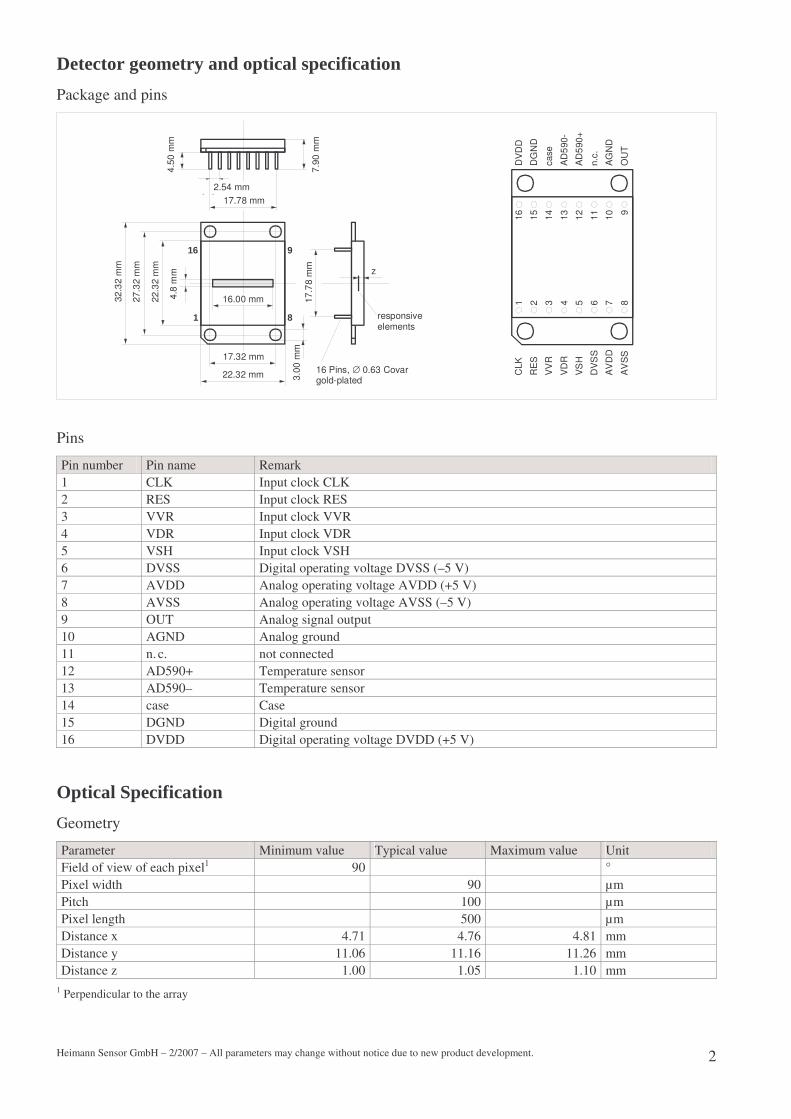
Detector geometry and optical specification
Package and pins
16 Pins, ∅ 0.63 Covargold-plated
17.78 mm
2.54 mm
16.00 mm
17.32 mm
22.32 mm
4.50
mm
7.90
mm
17.7
8 m
m3.
00 m
m
2.00
mm
22.3
2 m
m
27.3
2 m
m
32.3
2 m
m
z
responsiveelements
16
1 8
9
1 2 3 4 5 6 7 8910111213141516
CLK
RE
S
VV
R
VD
R
VS
H
VD
2
VD
D
VD
2
VD
D
GN
D
case
AD
590
+
AD
590
-
n.c.
GN
D
OU
T
Pins
Pin number Pin name Remark 1 CLK Input clock CLK (trigger on rising edge) 2 RES Input clock RES (active low) 3 VVR Input clock VVR (active high) 4 VDR Input clock VDR (active high) 5 VSH Input clock VSH (active high) 6 VD2 Operating voltage (+2.5 V) 7 VDD Operating voltage (+5 V) 8 VD2 Operating voltage (+2.5 V) 9 OUT Analog signal output 10 GND Ground 11 n. c. not connected 12 AD590+ Temperature sensor 13 AD590– Temperature sensor 14 case case 15 GND Ground 16 VDD Operating voltage (+5 V)
Connect Pin 6 to Pin 8 (VD2), Pin 7 to Pin 16 (VDD), Pin 10 to Pin 15 (GND)
Optical Specification
Geometry
Parameter Minimum value Typical value Maximum value Unit Field of view of each pixel1 90 ° Pixel width 42 µm Pixel length 100 µm Pitch 50 µm Distance x 4.71 4.76 4.81 mm Distance y 11.06 11.16 11.26 mm Distance z 1.00 1.05 1.10 mm
1 Perpendicular to the array
Position of the Pixels Transmission of the window

Heimann Sensor GmbH – 4/2007 – All parameters may change without notice due to new product development. 3
12.80 mm
y
x
z
Wavelength (µm)
0
1.0
Tra
nsm
issi
on
0.8
0.6
0.4
0.2
0.04 8 12 16 20
2–8 µm
8–14 µm
CaF2
Saphir
ZnSe
Electro-optical specification
Rectangular chopping with 128 Hz, array temperature 25 °C, black body source temperature 400 °C, filter transmission 100 %
Parameter Minimum value Typical value Maximum value Unit Responsivity SV 529 000 619 000 V/W Noise UN
0.71 0.9 mV NEP 1.1 1.6 nW MTF (R = 3 lp/mm) 0.4 0.6 Uniformity1 SV 2 5 % Operating temperature –15 70 °C
1 No defective elements
Typical responsivity Typical MTF
Frequency (Hz)
10 10 10
10
10
10 1 2 35
6
7
Re
spon
sivi
ty (
V/W
)
R (lp/mm)
0
1.0
MT
F
0.8
0.6
0.4
0.2
0.01 2 3 4 5
10 Hz
40 Hz
128 Hz

Heimann Sensor GmbH – 4/2007 – All parameters may change without notice due to new product development. 4
Electrical parameters
All values for VDD = 5 V, VD2 = 2.5 V
Parameter Minimum value Typical value Maximum value Unit VDD 4.75 5.0 5.25 V VD2 2.4 2.5 2.6 V Digital inputs Low voltage High voltage Switching threshold Leakage current
0
0.7 VDD
0.5 VDD
0.3 VDD
VDD
±1
V V V µA
Current consumption I 8 mA AD590 Operating voltage1 4 30 V
1 See data sheet of Analog Devices
Maximum/minimum conditions
All voltages refer to ground (pin 10, 15)
Parameter Maximum/minimum value Unit VDD, VD2 –0.3 to 7 V Digital inputs CLK, RES, VVR, VDR, VSH
–0.3 to VDD 0.3 V
Chopping frequency fCh 10 to 512 Hz AD590+ to AD590– 1 –20 to 44 V Analog output 2 ±5 mA Maximum irradiance 50 mW/mm2 Soldering temperature (10 s) 300 °C Storage temperature –20 to 80 °C
1 Potential free to ground (Pin 15), 2 Not short resistent

Heimann Sensor GmbH – 4/2007 – All parameters may change without notice due to new product development. 5
Clock parameters
All values for VDD = 5 V, VD2 = 2.5 V
Parameter Relative value Minimum value Typical value Maximum value Unit Chopping frequency1 fCh 10 128 512 Hz Readout clock CLK fCLK = 2 · fCh · 268 1 / tCLK 0 69 300 kHz Reset clock low-impulse duration tRES 1/2 tCLK 1.8 7.5 µs Clock VVR high-impulse duration tVVR 2 tCLK 7.5 30 µs Clock VDR high-impulse duration tVDR 28 tCLK ² 200 400 µs Clock VSH high-impulse duration tVSH 1 tCLK 3.5 15 µs Settling time at the output tout 1 µs
1 tCh low = tCh high
2 for fCh = 512 Hz tVDR should be 56 · tCLK = 200 µs
Clock diagram
0 1 2 3 14 130 131 13215 133
RES
CLK
VVR
VDR
VSH
ADC-sample
output
1294
4
integration time tint
2 24 26 2562542521 3 23 2522
lowpass settling time (tVDR - tVVR)
1/2 chopper period (1/2f_ch)
anal
ogue
pre
set,
inte
gra
tion,
sam
ple
& h
old
read
out o
f pr
evio
us
hold
ana
log
ue d
ata
253 255

Heimann Sensor GmbH – 2/2007 – All parameters may change without notice due to new product development. 1
HPS 128-LTI-S – Hybrid pyroelectric linear array with 128 responsive elements and integrated CMOS multiplexer Description Features The pyroelectric linear array 128-LTI-S is a hybrid detector with 128 responsive elements and an integrated CMOS multiplexer.
The pyroelectric chip consists of lithium tantalate (Li-TaO3). The size of the responsive elements is (90 x 500) µm2 with a pitch of 100 µm (90 x 1000 µm² available on request). The multiplexer includes low-noise preamplifiers for each pixel, analogue switches and an output amplifier. The pre-amplifiers transform the signal charges of each pixel in a signal voltage, realize a band limiting and give the ampli-fied signal to the sample&hold for the read-out process. The digital inputs are CMOS compatible.
For the measurement of the detector temperature a sen-sor (type AD 590) is integrated. It provides a temperature proportional current.
The pyroelectric chip and the read-out circuit are ar-ranged in a metal hermetic package with an infrared win-dow. It determines the spectral responsivity.
For the measurement of the infrared radiation it is neces-sary to chop the radiation flux.
• 128 responsive elements arranged in a line
• Coated germanium or silicon as infrared window
• Broad band windows or special filters are possible on request
• NEP (128 Hz) = 4 nW (typical) • Dynamic range > 75 dB • Integrated CMOS multiplexed • Good long-term stability • Simple mode of operation • Operation at ambient temperatures • Small package
Readout-circuit
Sample & Hold Multiplexer
CH
CA
CTP
RTP
CS
CP
uA
iP
V VR
VSH
Q/V-Converter LowpassResponsiveElement
Amplifier Output
+
–
CF
V DR
+
–+1 +1

Heimann Sensor GmbH – 2/2007 – All parameters may change without notice due to new product development. 2
Detector geometry and optical specification Package and pins
16 Pins, ∅ 0.63 Covargold-plated
17.78 mm2.54 mm
16.00 mm
17.32 mm
22.32 mm
4.50
mm
7.90
mm
17.7
8 m
m3.
00 m
m
4.8
mm
22.3
2 m
m
27.3
2 m
m
32.3
2 m
m
z
responsiveelements
16
1 8
9
1 2 3 4 5 6 7 8910111213141516
CLK
RE
S
VV
R
VD
R
VS
H
DV
SS
AV
DD
AV
SS
DV
DD
DG
ND
case
AD
590+
AD
590-
n.c.
AG
ND
OU
T
Pins
Pin number Pin name Remark 1 CLK Input clock CLK 2 RES Input clock RES 3 VVR Input clock VVR 4 VDR Input clock VDR 5 VSH Input clock VSH 6 DVSS Digital operating voltage DVSS (–5 V) 7 AVDD Analog operating voltage AVDD (+5 V) 8 AVSS Analog operating voltage AVSS (–5 V) 9 OUT Analog signal output 10 AGND Analog ground 11 n. c. not connected 12 AD590+ Temperature sensor 13 AD590– Temperature sensor 14 case Case 15 DGND Digital ground 16 DVDD Digital operating voltage DVDD (+5 V)
Optical Specification Geometry
Parameter Minimum value Typical value Maximum value Unit Field of view of each pixel1 90 ° Pixel width 90 µm Pitch 100 µm Pixel length 500 µm Distance x 4.71 4.76 4.81 mm Distance y 11.06 11.16 11.26 mm Distance z 1.00 1.05 1.10 mm
1 Perpendicular to the array

Heimann Sensor GmbH – 2/2007 – All parameters may change without notice due to new product development. 3
Position of the Pixels Transmission of the germanium window
12.80 mm
y
x
z
Wavelength (µm)
0
1.0
Tran
smis
sion
0.8
0.6
0.4
0.2
0.04 8 12 16 20
Ge*
Si*
Electro-optical specification Rectangular chopping with 128 Hz, array temperature 25 °C
Parameter Minimum value Typical value Maximum value Unit Responsivity SV 350000 500000 V/W Noise UN
2 4 mV NEP 4 8 nW MTF (R = 3 lp/mm) 0.4 0.6 Uniformity1 SV 2 5 % Operating temperature –15 70 °C
1 No defective elements
Typical responsivity Typical MTF
Frequency (Hz)
10 10 10
10
10
10 1 2 35
6
7
Res
pons
ivity
(V/W
)
R (lp/mm)
0
1.0
MTF
0.8
0.6
0.4
0.2
0.01 2 3 4 5
10 Hz
40 Hz
128 Hz

Heimann Sensor GmbH – 2/2007 – All parameters may change without notice due to new product development. 4
Electrical parameters All values for DVDD = AVDD = 5 V, AVSS = DVSS = –5 V
Parameter Minimum value Typical value Maximum value Unit AVDD, DVDD1 4.75 5.0 5.25 V AVSS, DVSS1 –5.25 –5.0 –4.75 V Digital inputs Low voltage High voltage Switching threshold Leakage current
0
0.7 DVDD
0.5 DVDD
0.3 DVDD
DVDD
±1
V V V µA
Current consumption Ianalog 8 mA Current consumption Idigital 30 µA AD590 Operating voltage2 +4 +30 V
1 AVDD and DVDD; AVSS and DVSS must be connect together direct at the detector, 2 See data sheet of Analog Devices Maxiumum/minimum conditions All voltages refer to ground (pin 15)
Parameter Maximum/minimum value Unit DVDD, AVDD –0.3 to +7 V AVSS, DVSS +0.3 to –7 V Digital inputs CLK, RES, VVR, VDR, VSH
–0.3 to DVDD +0.3 V
Chopping frequency fCh 10 to 300 Hz AD590+ to AD590– 1 –20 to +44 V Analog output 2 ±5 mA Maximum irradiance 50 mW/mm2 Soldering temperature (10 s) 300 °C Storage temperature –20 to 80 °C
1 Potential free to ground (Pin 15), 2 Not short resistent Clock parameters All values for DVDD = AVDD = 5 V, AVSS = DVSS = –5 V
Parameter Minimum value Typical value Maximum value Unit Chopping frequency1 fCh 10 128 200 Hz Ground clock1 CLK fclk 0 34.3 100 kHz Reset clock high-impulse duration tres 2.5 4 µs Clock VVR high-impulse duration tVVR 10 15 µs Clock VDR high-impulse duration tVDR 200 300 µs Clock VSH low-impulse duration tSH 10 15 µs Settling time at the output tout 3 5 µs Setup time before clock t128SH 10 µs Time distance tSHres 10 µs Time distance tSHVVR 10 µs Time distance tSHfCh 0 µs Time distance tfChres 0 µs Time distance tclkres 0 µs Time distance tresclk 1 µs Time distance tresout 1.5 tclk + tresclk µs Time distance tDRVR 0 µs Time distance tVRDR 0 µs
1 tCh low = tCh high

Heimann Sensor GmbH – 2/2007 – All parameters may change without notice due to new product development. 5
Clock diagram
Pixel128 Pixel0 Pixel1
fCh
fclk
Output
VSH
VDR
VVR
VRES
tout
tVDR
tVRDR
tDRVR
tVVR
tresclk
tres
tfChres
tSHres
tSH
t128SH
tSHVVR
tclkres
tSHfCh
tresout
Remark: pixel 0 is an input without responsive element (dark signal)
Application remarks Typical clock regime
Parameter Relative value Typical value Unit Chopping frequency fCh 128 Hz Ground clock fclk 1 / tclk 34 304 Hz Reset clock high-impulse duration tres ¼ tclk 7.3 µs Clock VVR high-impulse duration tVVR 3 tclk 29.2 µs Clock VDR high-impulse duration tVDR 10 tclk 292 µs Clock VSH low- impulse duration tSH ½ tclk 14.6 µs
Clock diagram
fC h
fclk
VRES
VVR
VDR
VSH
Output
Clocknb.
Sample
1331321311300 1 2 10 11
Pixel0 Pixel9Pixel8 Pixel128
Remark: Clock 133 is for the compensation of jitter of the chopping frequency during the mechanical chopping

Heimann Sensor GmbH – 2/2007 – All parameters may change without notice due to new product development. 1
HPS128-LT-S – Hybrid pyroelectric linear array with 128 responsive elements and integrated CMOS multiplexer Description Features The pyroelectric linear array 128-LT is a hybrid detector with 128 responsive elements and an integrated CMOS multiplexer.
The pyroelectric chip consists of lithium tantalate (Li-TaO3). The size of the responsive elements is (90 x 500) µm2 with a pitch of 100 µm (90 x 1000 µm² available on request). The multiplexer includes low-noise preamplifiers for each pixel, analogue switches and an output amplifier. The pre-amplifiers transform the signal charges of each pixel in a signal voltage, realize a band limiting and give the ampli-fied signal to the sample&hold for the read-out process. The digital inputs are CMOS compatible.
For the measurement of the detector temperature a sen-sor (type AD 590) is integrated. It provides a temperature proportional current.
The pyroelectric chip and the read-out circuit are ar-ranged in a metal hermetic package with an infrared win-dow. It determines the spectral responsivity.
For the measurement of the infrared radiation it is neces-sary to chop the radiation flux.
• 128 responsive elements arranged in a line
• Coated germanium or silicon as infrared window
• Broad band windows or special filters are possible on request
• NEP (128 Hz) = 7 nW (typical) • Dynamic range > 75 dB • Integrated CMOS multiplexed • Good long-term stability • Simple mode of operation • Operation at ambient temperatures • Small package
Readout-circuit
Sample & Hold Multiplexer
CH
CA
CTP
RTP
CS
CP
uA
iP
V VR
VSH
Q/V-Converter LowpassResponsiveElement
Amplifier Output
+
–
CF
V DR
+
–+1 +1
Heimann Sensor GmbH – 2/2007 – All parameters may change without notice due to new product development. 2
Detector geometry and optical specification Package and pins
16 Pins, ∅ 0.63 Covargold-plated
17.78 mm2.54 mm
16.00 mm
17.32 mm
22.32 mm
4.50
mm
7.90
mm
17.7
8 m
m3.
00 m
m
4.8
mm
22.3
2 m
m
27.3
2 m
m
32.3
2 m
m
z
responsiveelements
16
1 8
9
1 2 3 4 5 6 7 8910111213141516
CLK
RE
S
VV
R
VD
R
VS
H
DV
SS
AV
DD
AV
SS
DV
DD
DG
ND
case
AD
590+
AD
590-
n.c.
AG
ND
OU
T
Pins
Pin number Pin name Remark 1 CLK Input clock CLK 2 RES Input clock RES 3 VVR Input clock VVR 4 VDR Input clock VDR 5 VSH Input clock VSH 6 DVSS Digital operating voltage DVSS (–5 V) 7 AVDD Analog operating voltage AVDD (+5 V) 8 AVSS Analog operating voltage AVSS (–5 V) 9 OUT Analog signal output 10 AGND Analog ground 11 n. c. not connected 12 AD590+ Temperature sensor 13 AD590– Temperature sensor 14 case Case 15 DGND Digital ground 16 DVDD Digital operating voltage DVDD (+5 V)
Optical Specification Geometry
Parameter Minimum value Typical value Maximum value Unit Field of view of each pixel1 90 ° Pixel width 90 µm Pitch 100 µm Pixel length 500 µm Distance x 4.71 4.76 4.81 mm Distance y 11.06 11.16 11.26 mm Distance z 1.00 1.05 1.10 mm
1 Perpendicular to the array

Heimann Sensor GmbH – 2/2007 – All parameters may change without notice due to new product development. 3
Position of the Pixels Transmission of the germanium window
12.80 mm
y
x
z
Wavelength (µm)
0
1.0
Tran
smis
sion
0.8
0.6
0.4
0.2
0.04 8 12 16 20
Ge*
Si*
Electro-optical specification Rectangular chopping with 128 Hz, array temperature 25 °C
Parameter Minimum value Typical value Maximum value Unit Responsivity SV 140000 200000 V/W Noise UN
1.5 3 mV NEP 7 15 nW MTF (R = 3 lp/mm) 0.4 0.6 Uniformity1 SV 1 3 % Operating temperature –15 70 °C
1 No defective elements
Typical responsivity Typical MTF
Frequency (Hz)
10 10 10
10
10
10 1 2 35
6
7
Res
pons
ivity
(V/W
)
R (lp/mm)
0
1.0
MTF
0.8
0.6
0.4
0.2
0.01 2 3 4 5
10 Hz
40 Hz
128 Hz

Heimann Sensor GmbH – 2/2007 – All parameters may change without notice due to new product development. 4
Electrical parameters All values for DVDD = AVDD = 5 V, AVSS = DVSS = –5 V
Parameter Minimum value Typical value Maximum value Unit AVDD, DVDD1 4.75 5.0 5.25 V AVSS, DVSS1 –5.25 –5.0 –4.75 V Digital inputs Low voltage High voltage Switching threshold Leakage current
0
0.7 DVDD
0.5 DVDD
0.3 DVDD
DVDD
±1
V V V µA
Current consumption Ianalog 8 mA Current consumption Idigital 30 µA AD590 Operating voltage2 +4 +30 V
1 AVDD and DVDD; AVSS and DVSS must be connect together direct at the detector, 2 See data sheet of Analog Devices Maxiumum/minimum conditions All voltages refer to ground (pin 15)
Parameter Maximum/minimum value Unit DVDD, AVDD –0.3 to +7 V AVSS, DVSS +0.3 to –7 V Digital inputs CLK, RES, VVR, VDR, VSH
–0.3 to DVDD +0.3 V
Chopping frequency fCh 10 to 300 Hz AD590+ to AD590– 1 –20 to +44 V Analog output 2 ±5 mA Maximum irradiance 50 mW/mm2 Soldering temperature (10 s) 300 °C Storage temperature –20 to 80 °C
1 Potential free to ground (Pin 15), 2 Not short resistent Clock parameters All values for DVDD = AVDD = 5 V, AVSS = DVSS = –5 V
Parameter Minimum value Typical value Maximum value Unit Chopping frequency1 fCh 10 128 200 Hz Ground clock1 CLK fclk 0 34.3 100 kHz Reset clock high-impulse duration tres 2.5 4 µs Clock VVR high-impulse duration tVVR 10 15 µs Clock VDR high-impulse duration tVDR 200 300 µs Clock VSH low-impulse duration tSH 10 15 µs Settling time at the output tout 3 5 µs Setup time before clock t128SH 10 µs Time distance tSHres 10 µs Time distance tSHVVR 10 µs Time distance tSHfCh 0 µs Time distance tfChres 0 µs Time distance tclkres 0 µs Time distance tresclk 1 µs Time distance tresout 1.5 tclk + tresclk µs Time distance tDRVR 0 µs Time distance tVRDR 0 µs
1 tCh low = tCh high

Heimann Sensor GmbH – 2/2007 – All parameters may change without notice due to new product development. 5
Clock diagram
Pixel128 Pixel0 Pixel1
fCh
fclk
Output
VSH
VDR
VVR
VRES
tout
tVDR
tVRDR
tDRVR
tVVR
tresclk
tres
tfChres
tSHres
tSH
t128SH
tSHVVR
tclkres
tSHfCh
tresout
Remark: pixel 0 is an input without responsive element (dark signal)
Application remarks Typical clock regime
Parameter Relative value Typical value Unit Chopping frequency fCh 128 Hz Ground clock fclk 1 / tclk 34 304 Hz Reset clock high-impulse duration tres ¼ tclk 7.3 µs Clock VVR high-impulse duration tVVR 3 tclk 29.2 µs Clock VDR high-impulse duration tVDR 10 tclk 292 µs Clock VSH low- impulse duration tSH ½ tclk 14.6 µs
Clock diagram
fC h
fclk
VRES
VVR
VDR
VSH
Output
Clocknb.
Sample
1331321311300 1 2 10 11
Pixel0 Pixel9Pixel8 Pixel128
Remark: Clock 133 is for the compensation of jitter of the chopping frequency during the mechanical chopping

Evaluation Kit für PYROSENS Arrays128/256/510-LT/LTI
BedienungsanleitungManual
DIAS Infrared GmbH

21
Table of contentsGeneral information 22
General advice and safety regulations 23
Intended usage .......................................................................................................................................................23 Use and maintenance of the pyrometer..................................................................................................................23 Modifications .........................................................................................................................................................23 Environmental protection.......................................................................................................................................23
Maintenance and warranty 24
Maintenance...........................................................................................................................................................24 Packing and storage ...............................................................................................................................................24 Warranty ................................................................................................................................................................24 Declaration.............................................................................................................................................................24
Introduction and installation 25
Scope of delivery ...................................................................................................................................................25 Application range...................................................................................................................................................25 Circuit description..................................................................................................................................................25 Installation .............................................................................................................................................................26 Parameters and limit values ...................................................................................................................................26 Circuit diagram ......................................................................................................................................................28 Views and dimensions ...........................................................................................................................................30
Software 32
Start of program.....................................................................................................................................................32 Parameters and functions .......................................................................................................................................33
Detector parameters ....................................................................................................................................33 Recorder and replay function......................................................................................................................33 Data acquisition ..........................................................................................................................................34
Pixel display...........................................................................................................................................................34 Diagram options .........................................................................................................................................35 Menu bar.....................................................................................................................................................35 Structure of record file................................................................................................................................36

22 Evaluation Kit
C H A P T E R 6
General information
We are pleased that you decided for an Evaluation Kit for PYROSENS arrays 128/256/510 LT/LTI.
Please read this manual carefully before beginning any operation with the Evalution Kitand keep it in a save place. It contains all the necessary information for set up and longterm operation of the pyrometer.
If you have any questions to Evalution Kit, we would ask you to read this manual first.
Should you still have any open questions, notice any errors in this manual or wish to pass on any tips and suggestions for improvement, please inform your supplier or contact us directly: DIAS Infrared GmbH Pforzheimer Straße 21 D 01189 DRESDEN Tel.: +49 351 896 74 0 Fax: +49 351 896 74 99 Email: info@dias infrared.dewww: http://www.dias infrared.de
This way, you help us to provide you with the best possible product and correct documentation.

Chapter 7 General advice and safety regulations 23
C H A P T E R 7
General advice and safety regulations
In this chapterIntended usage......................................................................................................23Use and maintenance of the pyrometer ................................................................23Modifications .......................................................................................................23Environmental protection .....................................................................................23
Intended usageThis Evalution Kit provides the necessary voltages and clock pulses for the above mentioned pyroelectric arrays and converts their output signal into digital values. If you use the Evalution Kit not compliant to the description in this user manual it may causeloss of all warranty claims against the manufacturer.
Use and maintenance Use of the Evalution Kit is restricted to qualified personnel which has got instructions before initial operation and handling. Instructions should be given by a supervisor or optionally by DIAS Infrared GmbH customer service.
ModificationsIt is strongly prohibited to do technical modifications of the Evalution Kit without permission of the manufacturer. Contraventions absolve the manufacturer from liability for any damages. It automatically causes loss of all warranty claims against the manufacturer.
Environmental protectionThe unit may not be disposed of with normal waste, for disposal send the device back to DIAS Infrared GmbH, Pforzheimer Straße 21, 01189 Dresden, Germany.
Disposal (in accordance with RL2002/96/EC)

24 Evaluation Kit
C H A P T E R 8
Maintenance and warranty
In this chapterMaintenance .........................................................................................................24Packing and storage ..............................................................................................24Warranty...............................................................................................................24Declaration ...........................................................................................................24
Maintenance The Evalution Kit does not need any maintenance.
Packing and storage If the original packaging is not available, please use a shock proof package for shipment of the Evalution Kit. For overseas shipment or long term storage in rooms with high humidity the Evalution Kit should be heat sealed to protect it against humidity.
Warranty DIAS Infrared GmbH will replace or repair defective parts, which result from design errors or manufacturing faults, within a period of two years from the date of sale. Special terms can be arranged, in writing, at the time of purchase of the equipment. Devices, for which the return under warranty has been approved, should be sent to DIAS Infrared GmbH. The warranty is invalidated if the device is opened, disassembled, modified, or otherwise destroyed, without obtaining prior written approval from DIAS. The warranty is also invalidated if the device is improperly used, or if it is operated or stored under conditions which do not correspond to those defined in the technical specification. DIAS Infrared GmbH does not accept liability for any damage or losses which might occur, including financial losses and consequential damages, as a result of use of the equipment, or which occurs as a result of defects in the design or manufacture of the device. The seller does not give any warranty or assurances, that the equipment can be utilized for any special applications which the customer might have.
Declaration Changes in the interests of technical progress or changes that go back to amendedstatutory provisions stay reserved during delivery time if the delivery item is not substantially changed and therefrom the serviceability is not touched, the value is preserved or increased and the changes are reasonable for the purchaser.

Chapter 9 Introduction and installation 25
C H A P T E R 9
Introduction and installation
In this chapterScope of delivery..................................................................................................25Application range ................................................................................................. 25Circuit description ................................................................................................25Installation............................................................................................................26Parameters and limit values..................................................................................26Circuit diagram.....................................................................................................28Views and dimensions..........................................................................................30
Scope of delivery� Evalution Board � 9 V power supply� USB cable� SoftwarePlease note: The PYROSENS array is not included in the scope of delivery. It has to be ordered seperately.
Application rangeThis Evalution Kit provides the necessary voltages and clock pulses for the above mentioned pyroelectrical arrays and converts their output signal into digital values.
These values can be displayed and saved in a software, that runs on a computer connected via USB. You can make parameter settings with this software, too and start/stop the operation of the Evalution Kit.
The power supply of the Evalution Kit is made alternatively via USB connection of the computer or with an external 9 V power supply.
This Evalution Kit provides an impulse for the synchronization of external electronics.
Circuit descriptionThe pyroelectrical arrays need two supply voltages (5 V and 2.5 V) and five clocks (VCLK, VRES, VVR, VDR, VSH).
The analog output signals are read via one output (OUT1 for 128/256 LT/LTI) respectively via two outputs (OUT1/OUT2 for 510 LT/LTI).
There is a temperature detector “Analog Devices AD590” inside the arrays which represents a temperature controlled current source with 1 μA/K (output T Sen).

26 Evaluation Kit
The power supply of the Evalution Kit is made either via the 5 V USB connection of the computer or via the external power supply that is connected with the DC plug socket X3. The external voltage is down regulated by IC U5 to 5V. The IC U6 with switches the 5 V supply of the module when a power supply is connected from USB 5 V to external voltage. The source of the 5 V supply is displayed by a green LED (supply via external power supply) respectively by a red LED (supply via USB).
Please note: The supply with an external power supply causes less failures in the output signals of the arrays.
The IC U2 generates the 2.5 V voltage for the arrays.
The analog signals are buffered by OPV U7 and are lead directly to the inputs, that are configured as A/D converter (pin 25, 26), of the microcontroller U1.
The microcontroller communicates via a serial interface (TXD/RXD on pin 21, 22) which is implemented with IC U3 to USB and is read out at plug connector X2.
The pin connector X4 provides at pin 3 a voltage of 5 V for the connection of additional components, ampacity max. 250 mA.
The Evalution Kit offers synchronously an impulse at pin connector X5/pin 1 for the read out of the array , with a level 0/5 V whose polarity, length and phase length can be adjusted and turned on/off via software.
Installation � Install software on the computer
� Put the PYROSENS array in plug in socket on demoboard, please note alignment of pin 1 (mark "1" on conductor plate)
� Put USB cable in USB plug socket on demoboard, connect USB cable with free USB port to the computer, (device driver is installed automatically when using first),voltage display on demoboard blinks red,
� Connect 9 V power supply with power socket,put 9 V plug in DC external plug socket on demoboard,voltage display on demoboard changes into green
� Start software (please refer chapter Software, on page 32)
Parameters and limit values Read out frequency: 128 LT(I): 1 … 150 lines/sec 256 LT(I): 1 … 100 lines/sec 510 LT(I): 1 … 50 lines/sec
Supply voltage on X3: 7 to 30 VCharging rate demoboard: 50 mA (at 9V)

Chapter 9 Introduction and installation 27
5V output on X4 pin3 (against GND X4 pin4):Ampacity I max 250 mA
Sync pulse on X5 Pin1 (against GND X5 pin2):level high/low 5 V/0 VAmpacity source/drain + / 100 mA
Dimensions (length/width/height) 70 mm/25 mm/24 mm

28 Evaluation Kit
Circuit diagram
Figure 1: circuit diagram

Chapter 9 Introduction and installation 29
Figure 2: Detailed view conductor plate, circuit side
Figure 3: Detailed view conductor plate, detector side

30 Evaluation Kit
Views and dimensions
Figure 4: Conductor plate, detector side

Chapter 9 Introduction and installation 31
Figure 5: conductor plate, views and dimensions [mm]

32 Evaluation Kit
C H A P T E R 1 0
Software
In this chapterStart of program....................................................................................................32Parameters and functions......................................................................................33Pixel display .........................................................................................................34
Start of program
(1) Find connected evaluation board and connect (2) Fade in detector parameter (3) Fade in record function
(3) Connect/Disconnect(4) Display detector temperature
(1)
(2)
(3)
(1) (2)

Chapter 10 Software 33
Parameters and functions
Detector parameters
(1) Adjust pixel amount of array (128, 256, 510)Please note: This value cannot be changed during measurement value acquisition!
(2) Adjust frequency of sample cycle. The maximum frequency depends on the pixel amount. Please note: By changing this value the values of VVR and VCD times change too.
(3) Response time of low pass. This value is generated by adjusting the VVR and VDR times. If necessary, the integration time (5) is changed.
(4) Adjust integration time. This value is generated by adjusting the VVR and VDR times. If necessary, the response time (4) is adjusted.
(5) Adjust VVR time. Response time and integration time change thereby.
(6) Adjust VDR time. Response time and integration time change thereby.
(7) Delay of sync impuls from the beginnung of sample loop (positive shoulder VVR respectively VDR impulse).
(8) Puls width of sync impulse
(9) Switching direction of sync impulse.
Recorder and replay function(1) Adjust page interval. Specification is made by the number of pages (e.g. [1]: every page is
recorded.; [10]: every tenth page is recorded. One page is the image of a detector array per sample intervall.
(2) Number of recorded pages
(3) File in which the record is made. If the file already exists, it gets overwritten.
(4) By chosing this option, date and time are prepend for every record.
(5) Chose file for replay
(6) Information about the replay file
(1) (2)
(6)
(7) (8)
(9)
(1)(2)
(3)
(3)
(4)(5)
(6)

34 Evaluation Kit
Replay
(1) Replay a record
(2) Select page. Every page equates to the image of the line array per sample period.
Data acquisition
(1) Threshold measurement trigger
(2) Activates measurement trigger. The display of the pixel values is only made when a pixel of the array content is above the value as specified in (2).
(3) Starts/Stops measurement value acquisition
(4) Release for record. When starting the measurement data acquisition, the record in a text file starts.
Pixel display
Every array alement equates to a bar in the diagram. Additionally, the pixel values are displayed as a line diagram.
Move in diagram:� Hold down the right mouse button in the diagram You can scroll the diagram now in
any direction. � Use the scroll bar (1) for the desired direction.
(1)(2)
(1)(2) (3) (4)
(1)
(2)
(2)

Chapter 10 Software 35
Select detail:� Select an area in the diagram with the left mouse button. The display of this area
gets zoomed in.� Change the size of the scroll bar (1) with the arrow marks (2)
Diagram options (1) Adjust diagramm to pixel values
(2) Reset diagram to default values
(3) Fade in/out bar display
(4) Fade in/out line display
(5) Statistical values about all pixels of the current array content
(6) Statistical values about all pixels since starting the data acquisition
(7) Reset values in (6)
Menu bar(1) Copy diagram as bitmap into clip board
(2) Save pixel values in a text file. Pixel number and pixel value are seperated by a semicolon.
(3) Close program
(1) (2)
(3) (4)(5)
(6)
(7)
(1) (2)(3)

36 Evaluation Kit
Structure of record fileThe record is saved as text file and can be viewed with every text editor. Furthermore, the data are structured so that they can be read directly into Microsoft Excel®.
Date: 05.11.2013 Information about recorded dataStart time: 15:45:32Stop time: 15:45:34Array size: 128Sample freq/Hz: 128Trigger level: inactivePage interval: 1Page counter: 101Page: 1 Page number1;1;2,510 Pixel value: [serial number];[pixel number];[meas.value] 1;2;2,5021;3;2,506..........Page: 22;1;2,6102;2;2,510

DIAS Infrared GmbH · Gostritzer Straße 65 · D-01217 Dresden · Germany
phone: +49 351 8717228 · fax: +49 351 8717230e-mail: [email protected] · internet: www.dias-infrared.com
Handling Precautions for Pyroelectric SensorsProtection from Electro-Static Discharges (ESD)
Caused by temperature changes during transportation or handling, pyroelectric detectors can generate avoltage of some hundreds of Volts.
By improper handling or storing, both the detectors themselves as well as the connected electronics canbe destroyed.
For that reason we deliver all our detectors in boxes with conductive foam similar to the one depictedbelow.
Please observe the following instructions:
� transportation and storage of pyroelectric sensors only with electrically connected pins (resistancebetween the pins <10 M�)
� handling of pyroelectric sensors only in ESD protected areas� temperature ramps exceeding a rate of 10 K/min must be avioded at the sensors
Cleaning Advise
Our sensors can be cleaned in isopropyl alcohol or ethanol or in water solutions of one of it. The sensorsshould not to be exposed to cleaning liquids longer than 10 min.
� for cleaning use only soft tools like brush, cotton wool or cellulose tissues� avoid pressure to the window during cleaning procedure� do not use ultrasonic cleaner� do not use other cleansing agents than the above recommended ones
For some special filter materials the cleaning instructions can differ from these instructions. In suchcases please watch the special cleaning instructions enclosed with the sensors in such cases.
conductive foam

DIAS Infrared GmbH · Gostritzer Straße 65 · D-01217 Dresden · Germany
phone: +49 351 8717228 · fax: +49 351 8717230e-mail: [email protected] · internet: www.dias-infrared.com
Limits of Mechanical Stress
Our pyroelectric sensors are hermetically sealed when shipped. Bending of the wires near glass pin feedthroughs by more than 15° without suitable tools can lead to cracks in the glass seals.
Mechanical strain to the sensor may cause cracks in the filter window sealing. In all that cases the sensorbecomes leaky and therefore, it doesn’t reach the promised properties.
F >1 N
F >
1 N
F >2 N
bend
twist
>2
mm
use tongs
<15°
Soldering instructions
Overheating and inadequate heat sinking during soldering can damage the sensor!
� Use only manual soldering considering the instructions belo.� Do not use soldering irons with a power of more than 25 W.� Use heat sinking and minimum soldering temperature and time respectively (at maximum 3 s at
280 °C or 5 s at 240 °C).� The minimum distance between TO39 header and PCB is 5 mm. Do not use shorter lead wires!
>5
mm

�
�
� � � � �
� � � � �
� � � �
� � � �
� � � � �
� � � � �
� � � � �� � � � �
� � � � � �
�
� � � �
� � � � �� � �
� � � � �
�� � � � � �
� � � � � � � �
� � �
�
�� � � � �
�
� � � � �
� � � � � � � �
� � ! " � !
# � $ � � � � % � � � � � & " # % % �
� � % � � � � � � �