high voltage - comar condensatori voltage (former medium voltage) power factor correction ......
TRANSCRIPT
High Voltage (former Medium Voltage)
Power Factor Correction
IEC / EN 62271-1
IEC / EN 62271-200

Medium Voltage insulation levels
IEC IEEE / ANSI Highest Voltage KVrms
Power-Frequency
KVrms
Lightning Impulse (BIL)
KVpeak
Highest Voltage KVrms
Power-Frequency
KVrms
Lightning Impulse (BIL)
KVpeak 3.6 10 20/40 2.4 15 45 7.2 20 40/60 5 19 60 12 28 60/75 8.7 26 75
17.5 38 75/95 15 34 95/110 24 50 95/125 25 40/50 125/150
36 70 145/170 34.5 70 200 BIL = Basic Insulation Level
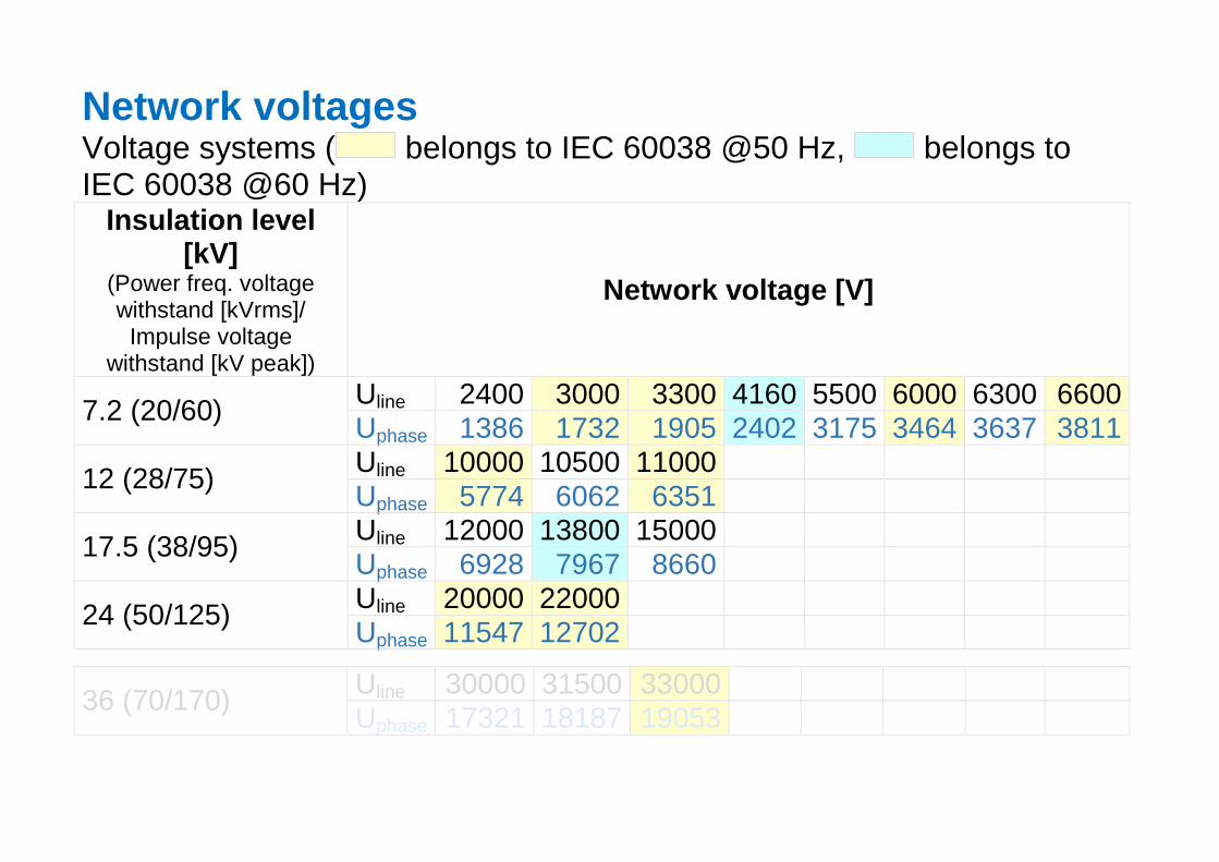
Network voltages Voltage systems ( belongs to IEC 60038 @50 Hz, belongs to IEC 60038 @60 Hz)
Insulation level [kV]
(Power freq. voltage withstand [kVrms]/
Impulse voltage withstand [kV peak])
Network voltage [V]
Uline 2400 3000 3300 4160 5500 6000 6300 6600 7.2 (20/60) Uphase 1386 1732 1905 2402 3175 3464 3637 3811 Uline 10000 10500 11000 12 (28/75) Uphase 5774 6062 6351 Uline 12000 13800 15000 17.5 (38/95) Uphase 6928 7967 8660 Uline 20000 22000 24 (50/125) Uphase 11547 12702
Uline 30000 31500 33000 36 (70/170) Uphase 17321 18187 19053

Available products
Capacitor units Capacitor banks (BMT) CTMT
Qn ≤ 450 kVAr Un ≤ 24 kV
CMMT Qn ≤ 600 kVAr Un ≤ 24 kV
Capacitor installations (MVcells) 1 stage inlet + 1 stage inlet + 3 stages 4 stages
Power factor correction of motors
Un ≤ 12kV
Un ≤ 24kV Un ≤ 24kV Un ≤ 36kV
~4000 kg W x D x H [mm] 3800 x 1700 x 2350
~800 .. 1400 kgW x D x H [mm]
1700 x 1150 x 2200
~8800 g W x D x H [mm] 7900 x 1700 x 2350
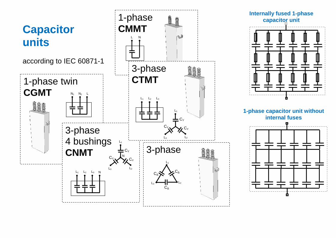
Capacitor units according to IEC 60871-1
1-phase CMMT
L N
3-phase
C∆
C∆ C∆
L1
L2 L3
1-phase twin CGMT N1 N2 L
3-phase 4 bushings CNMT
L1 L2 L3 N
CY
CY CY
L1
L2 L3
N
3-phase CTMT
CY
CY CY
L1
L2 L3
L1 L2 L3
Internally fused 1-phase capacitor unit
1-phase capacitor unit without internal fuses
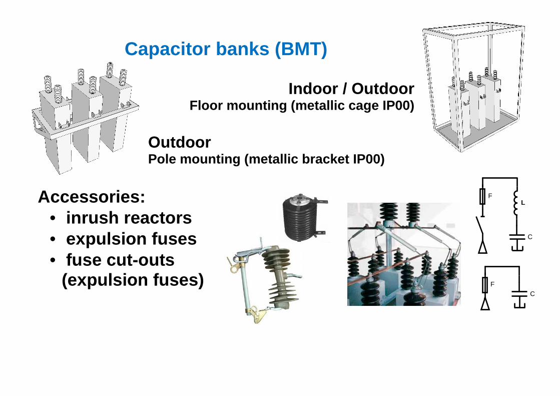
Capacitor banks (BMT)
Indoor / Outdoor Floor mounting (metallic cage IP00)
Outdoor Pole mounting (metallic bracket IP00)
Accessories: • inrush reactors • expulsion fuses • fuse cut-outs
(expulsion fuses)
L F
C
F
C
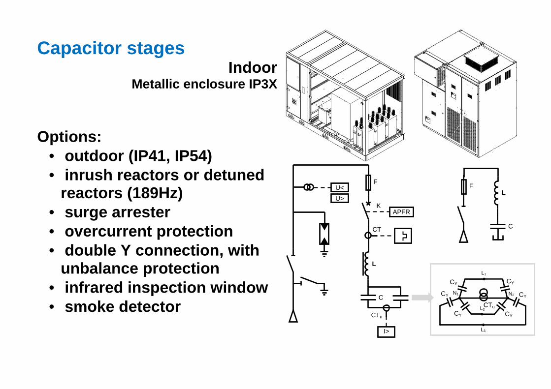
Capacitor stages Indoor
Metallic enclosure IP3X Options:
• outdoor (IP41, IP54) • inrush reactors or detuned
reactors (189Hz) • surge arrester • overcurrent protection • double Y connection, with
unbalance protection • infrared inspection window • smoke detector
U>
U<
CT
K APFR
L
I>
F
C
CTu
L F
C
CY
CY
CY
CY
CY
CY
CTu
L1
L2
L3
N1 N2
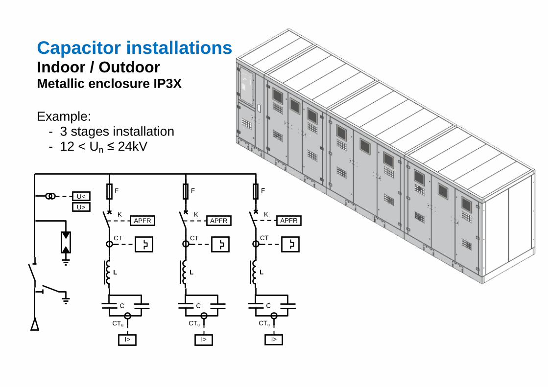
Capacitor installations Indoor / Outdoor Metallic enclosure IP3X Example:
- 3 stages installation - 12 < Un ≤ 24kV
U>
U<
CT
K APFR
L
I>
F
C
CTu
CT
K APFR
L
I>
F
C
CTu
CT
K APFR
L
I>
F
C
CTu
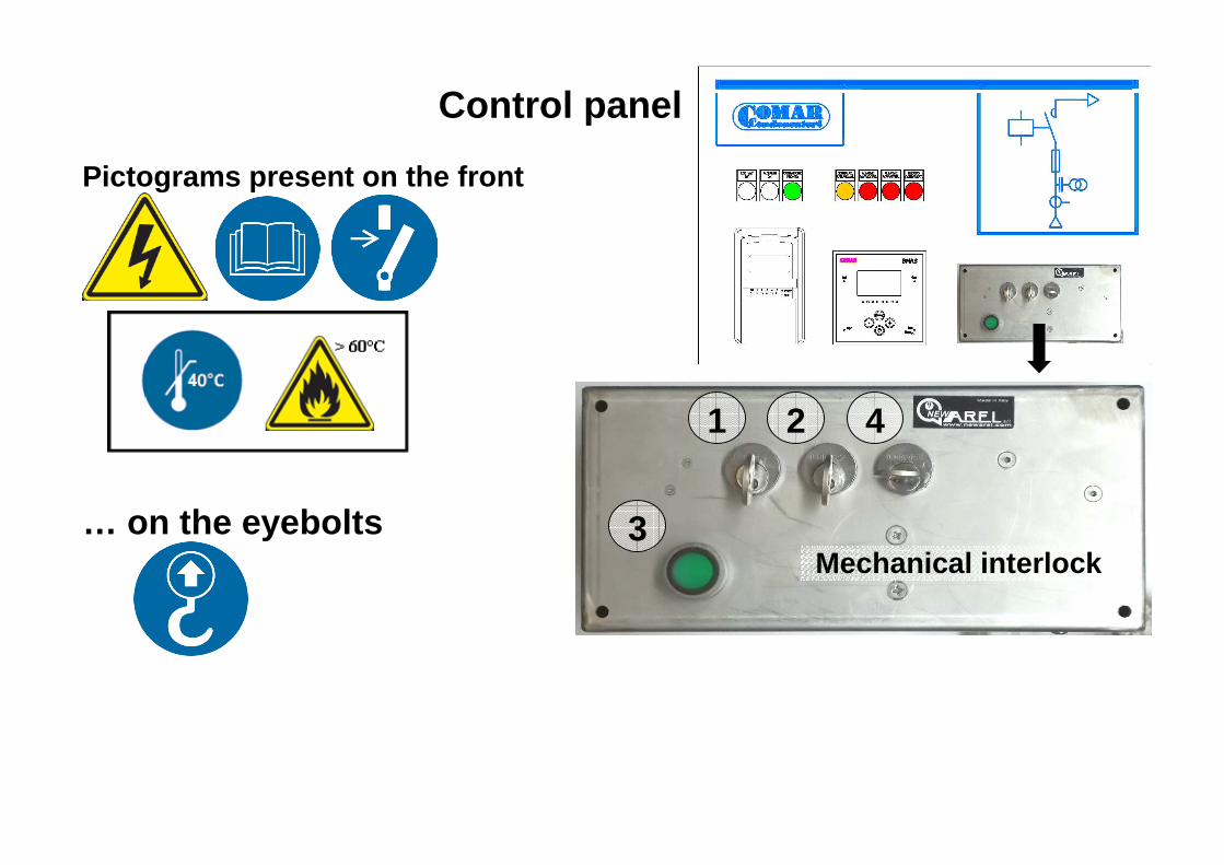
Control panel Pictograms present on the front
… on the eyebolts
Mechanical interlock
1 2
3
4
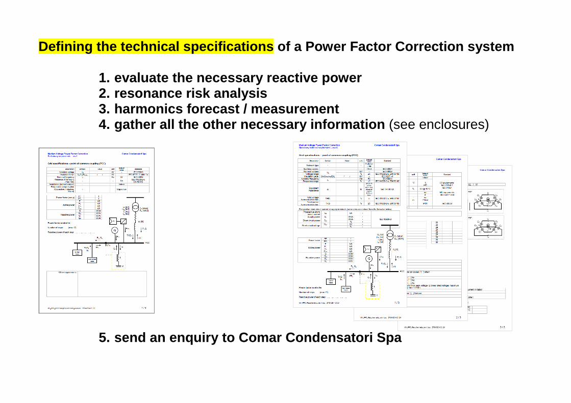
Defining the technical specifications of a Power Fac tor Correction system
1. evaluate the necessary reactive power 2. resonance risk analysis 3. harmonics forecast / measurement 4. gather all the other necessary information (see enclosures)
5. send an enquiry to Comar Condensatori Spa
Safety devices to protect the capacitor installatio n
Inside the capacitor unit • Fuse on each capacitor element • Pressure switch
Inside each capacitor stage • Overcurrent protection (1 protection relay + 3 Current Tran sformers) • Current Unbalance protection (YY configuration + 1 prote ction relay + 1
Current Transformer) • Detuned reactor • Over-temperature alarm
In the inlet stage of the capacitor installation • Overvoltage protection
Outside the capacitor installation • Smoke detector and Over-temperature alarm connected to the fire
protection system • Upstream Residual Current Device
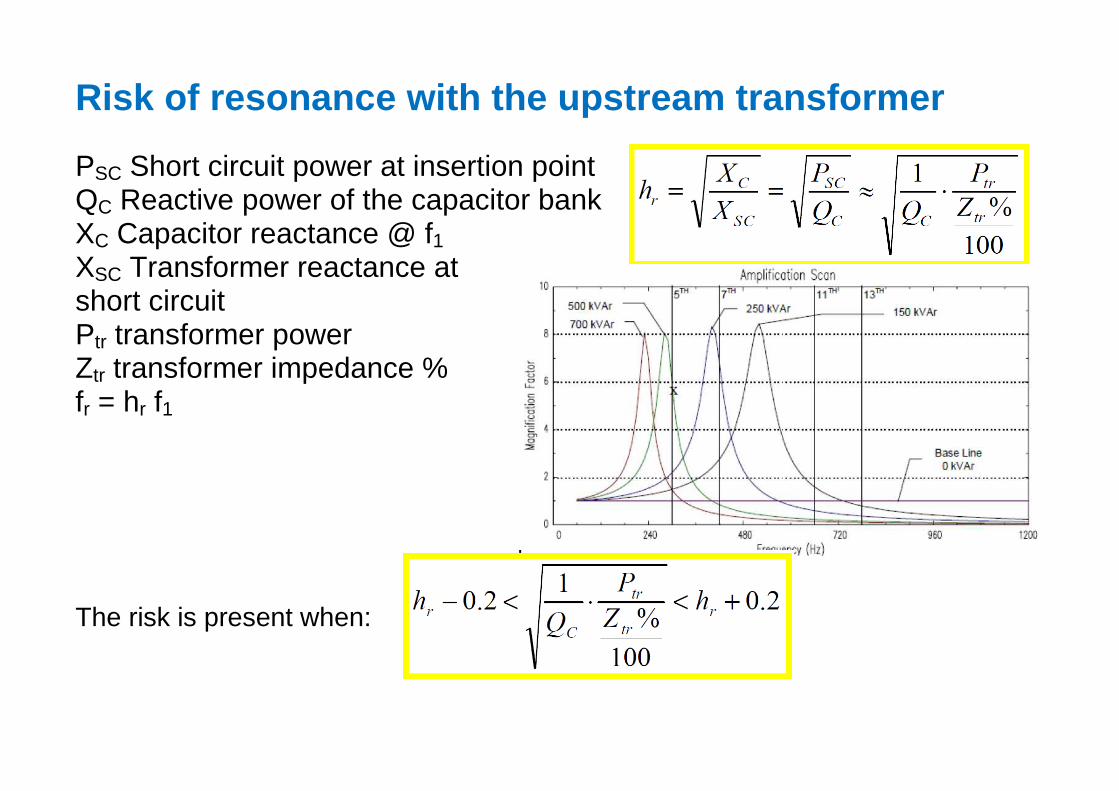
Risk of resonance with the upstream transformer PSC Short circuit power at insertion point QC Reactive power of the capacitor bank XC Capacitor reactance @ f1 XSC Transformer reactance at short circuit Ptr transformer power Ztr transformer impedance % fr = hr f1 The risk is present when: