pwr vessel internals
TRANSCRIPT
IAEA-TECDOC-1119
Assessment andmanagement of ageing of major
nuclear power plant componentsimportant to safety:
PWR vessel internals
October 1999

The originating Section of this publication in the IAEA was:
Engineering Safety SectionInternational Atomic Energy Agency
Wagramer Strasse 5P.O. Box 100
A-1400 Vienna, Austria
ASSESSMENT AND MANAGEMENT OF AGEING OFMAJOR NUCLEAR POWER PLANT COMPONENTS IMPORTANT TO SAFETY:
PWR VESSEL INTERNALSIAEA, VIENNA, 1999IAEA-TECDOC-1119
ISSN 1011–4289
© IAEA, 1999
Printed by the IAEA in AustriaOctober 1999

FOREWORD
At present, there are over four hundred operational nuclear power plants (NPPs) inIAEA Member States. Operating experience has shown that ineffective control of the ageingdegradation of the major NPP components (e.g. caused by unanticipated phenomena and byoperating, maintenance or manufacturing errors) can jeopardize plant safety and also plantlife. Ageing in these NPPs must be therefore effectively managed to ensure the availability ofdesign functions throughout the plant service life. From the safety perspective, this meanscontrolling within acceptable limits the ageing degradation and wear-out of plant componentsimportant to safety so that adequate safety margins remain, i.e. integrity and functionalcapability in excess of normal operating requirements.
This TECDOC is one in a series of reports on the assessment and management of ageingof the major NPP components important to safety. The reports are based on experience andpractices of NPP operators, regulators, designers, manufacturers, and technical supportorganizations and a widely accepted Methodology for the Management of Ageing of NPPComponents Important to Safety, which was issued by the IAEA in 1992.
The current practices for the assessment of safety margins (fitness-for-service) and theinspection, monitoring and mitigation of ageing degradation of selected components ofCanada deuterium–uranium (CANDU) reactors, boiling water reactors (BWRs), pressurizedwater reactors (PWRs), and water moderated, water cooled energy reactors (WWERs) aredocumented in the reports. These practices are intended to help all involved directly andindirectly in ensuring the safe operation of NPPs, and to provide a common technical basis fordialogue between plant operators and regulators when dealing with age related licensingissues. The guidance reports are directed at technical experts from NPPs and from regulatory,plant design, manufacturing and technical support organizations dealing with specific plantcomponents addressed in the reports.
This report addresses the pressurized water reactor vessel internals (taken as a singlecomponent). The IAEA acknowledges the work of all contributors to drafting and review ofthis report. In particular, the contributions of M. Brumovsky, Y. Dragunov, M. Erve,R. Havel, T. Mager, R. Mattis, A. Nonaka, and P. Petrequin are appreciated. Members of theInternational Working Group on Life Management of NPPs participated in this work. Theofficer responsible for this report was J. Pachner of the Division of Nuclear InstallationSafety.
EDITORIAL NOTE
In preparing this publication for press, staff of the IAEA have made up the pages from theoriginal manuscript(s). The views expressed do not necessarily reflect those of the IAEA, thegovernments of the nominating Member States or the nominating organizations.
Throughout the text names of Member States are retained as they were when the text wascompiled.
The use of particular designations of countries or territories does not imply any judgement bythe publisher, the IAEA, as to the legal status of such countries or territories, of their authorities andinstitutions or of the delimitation of their boundaries.
The mention of names of specific companies or products (whether or not indicated asregistered) does not imply any intention to infringe proprietary rights, nor should it be construed asan endorsement or recommendation on the part of the IAEA.
CONTENTS
1. INTRODUCTION................................................................................................................. 1
1.1. Background ..................................................................................................................... 11.2. Objective ......................................................................................................................... 21.3. Scope............................................................................................................................... 21.4. Structure.......................................................................................................................... 3
2. DESCRIPTION OF REACTOR VESSEL INTERNALS..................................................... 5
2.1. Western type PWR RVI.................................................................................................. 52.1.1. RVI constituent parts................................................................................................ 72.1.2. Materials................................................................................................................. 14
2.2. WWER type RVI .......................................................................................................... 152.2.1. RVI constituent parts.............................................................................................. 152.2.2. Materials................................................................................................................. 22
3. DESIGN BASIS, CODES, STANDARDS AND REGULATIONS................................... 25
3.1. Requirements in the USA ............................................................................................. 253.2. Requirements in France ................................................................................................ 273.3. Requirements in Germany ............................................................................................ 273.4. Requirements in Japan .................................................................................................. 273.5. Requirements in Russia................................................................................................. 28
4. OPERATING CONDITIONS ............................................................................................. 29
4.1. Temperature and neutron exposure............................................................................... 294.2. Primary coolant chemistry specifications ..................................................................... 31
5. AGEING MECHANISMS .................................................................................................. 33
5.1. Embrittlement ............................................................................................................... 335.1.1. Description of irradiation embrittlement................................................................ 335.1.2. Description of thermal ageing embrittlement......................................................... 345.1.3. Significance of embrittlement ................................................................................ 35
5.2. Fatigue........................................................................................................................... 355.2.1. Description ............................................................................................................. 355.2.2. Significance of fatigue............................................................................................ 36
5.3. Corrosion....................................................................................................................... 375.3.1. General corrosion ................................................................................................... 385.3.2. Stress corrosion cracking........................................................................................ 385.3.3. Erosion corrosion ................................................................................................... 41
5.4. Radiation induced creep, relaxation and swelling ........................................................ 425.4.1. Description ............................................................................................................. 425.4.2. Significance of irradiation creep and swelling....................................................... 42
5.5. Mechanical wear ........................................................................................................... 435.5.1. Description ............................................................................................................. 435.5.2. Significance of wear............................................................................................... 43
5.6. Handling........................................................................................................................ 43

6. INSPECTION AND MONITORING.................................................................................. 44
6.1. Inspection and monitoring methods.............................................................................. 446.2. National practices.......................................................................................................... 45
7. SERVICE EXPERIENCE AND RELATED MAINTENANCE........................................ 49
7.1. Failure of bolts and supporting beams of the thermal shields....................................... 497.2. Cracking of the guide tube support split pins ............................................................... 507.3. Cracking of fuel assembly alignment pins made from Inconel X-750.......................... 507.4. Baffle jetting ................................................................................................................. 507.5. Cracking of the baffle bolts........................................................................................... 507.6. Wear of bottom instrumentation thimbles. ................................................................... 527.7. Wear of control rod guides............................................................................................ 527.8. Handling incidents ........................................................................................................ 52
8. RVI AGEING MANAGEMENT PROGRAMME.............................................................. 53
8.1. Key elements of the ageing management programme.................................................. 558.1.1. Understanding ageing............................................................................................. 558.1.2. Co-ordination of the ageing management programme........................................... 558.1.3. Operation/use of reactor vessel internals................................................................ 568.1.4. Inspection, monitoring and assessment.................................................................. 568.1.5. Maintenance, repair and replacement..................................................................... 57
8.2. Application guidance .................................................................................................... 588.2.1. Embrittlement......................................................................................................... 588.2.2. Fatigue.................................................................................................................... 588.2.3. Stress corrosion cracking........................................................................................ 59
8.3. National and international R&D programmes .............................................................. 59
REFERENCES ........................................................................................................................ 61
ABBREVIATIONS.............................................................................................................................. 63
CONTRIBUTORS TO DRAFTING AND REVIEW............................................................. 65
1
1. INTRODUCTION
1.1. BACKGROUND
Managing the safety aspects of nuclear power plant (NPP) ageing requiresimplementation of effective programmes for the timely detection and mitigation of ageingdegradation of plant systems, structures and components (SSC) important to safety, so as toensure their integrity and functional capability throughout plant service life. General guidanceon NPP activities relevant to the management of ageing (maintenance, testing, examinationand inspection of SSC) is given in the International Atomic Energy Agency (IAEA) NuclearSafety Standards (NUSS) Code on the Safety of Nuclear Power Plants: Operation [1] andassociated Safety Guides on in-service inspection [2], maintenance [3] and surveillance [4].
The Operation Code requires that NPP operating organizations prepare and carry out aprogramme of periodic maintenance, testing, examination and inspection of plant SSCimportant to safety to ensure that their level of reliability and effectiveness remains in accordwith the design assumptions and intent and that the safety status of the plant has not beenadversely affected since the commencement of operation. This programme is to take intoaccount the operational limits and conditions, any other applicable regulatory requirements,and be re-evaluated in the light of operating experience. The associated Safety Guides providefurther guidance on NPP programmes and activities that contribute to timely detection andmitigation of ageing degradation of SSC important to safety.
The Safety Guide on In-Service Inspection [2] provides recommendations on methods,frequency and administrative measures for the in-service inspection programme for criticalsystems and components of the primary reactor coolant system aimed at detecting possibledeterioration due to the influences of stress, temperature, radiation, etc. and at determiningwhether they are acceptable for continued safe operation of the plant or whether remedialmeasures are needed. Organizational and procedural aspects of establishing and implementingan NPP programme of preventive and remedial maintenance to achieve design performancethroughout the operational life of the plant are covered in the Maintenance Safety Guide [3].Guidance and recommendations on surveillance activities for SSC important to safety (i.e.monitoring plant parameters and systems status, checking and calibrating instrumentation,testing and inspecting SSC, and evaluating results of these activities) are provided in theSurveillance Safety Guide [4]. The aim of the surveillance activities is to verify that the plantis operated within the prescribed operational limits and conditions, to detect in time anydeterioration of SSC as well as any adverse trend that could lead to an unsafe condition, and tosupply data to be used for assessing the residual life of SSC. The above Safety Guides providegeneral guidance, but do not give detailed technical advice for particular SSC.
Programmatic guidance on ageing management is given in the reports entitled“Methodology for the Management of Ageing of Nuclear Power Plant Components Importantto Safety” [5] and “Data Collection and Record Keeping for the Management of NuclearPower Plant Ageing [6]”. Guidance provided in these reports served as a basis for thedevelopment of component specific technical documents (TECDOCs) on the Assessment andManagement of Ageing of Major NPP Components Important to Safety. This publication onpressurized water reactor (PWR) vessel internals is one of such TECDOCs.
The primary function of the reactor vessel internals (RVI) is to support the core, thecontrol rod assemblies, the core support structure, and the reactor pressure vessel (RPV)
2
surveillance capsules. The reactor internals have the additional function to direct the flow ofthe reactor coolant and provide shielding for the reactor pressure vessel. The original designand subsequent operation of reactor internals was for the Shippingport plant, an experimentalpower reactor in the USA which started operation in the early 1960s. The design of the reactorinternals for the Yankee Rowe nuclear power plant, the first commissioned commercial lightwater reactor in the world, has not changed significantly over the past thirty-five years.
Pressurized water reactors are operating in Argentina, Armenia, Belgium, Brazil,Bulgaria, China, Croatia, the Czech Republic, Finland, France, Germany, Hungary, Italy,Japan, the Republic of Korea, the Netherlands, Slovakia, South Africa, Spain, Sweden,Switzerland, Taiwan (China), Russia, Ukraine, the United Kingdom and the United States ofAmerica. The history of commercial pressurized water reactor internals throughout the worldis one of safe, relatively trouble-free operation. The reactor internals are designed to withstandsteady state and fluctuating forces produced under handling, normal operation, transient andaccident conditions. The load restriction and fatigue life on as fabricated reactor internals aregoverned by code or regulatory bodies throughout the world. The reactor internals aresubjected to neutron irradiation as well as exposure to the primary coolant. The radiation andservice condition or environment must be taken into consideration when assessing andmanaging ageing of the reactor internals.
Reactor vessel internals are fabricated in accordance with strict quality assuranceprogrammes. Information on how the reactor vessel internals were produced is welldocumented. All the austenitic stainless steel used to fabricate the reactor vessel internals aresubject to stress corrosion testing prior to constructing the reactor vessel internals. In the USA,a United States Nuclear Regulatory Guide was published requiring the prevention ofsensitized stainless steel material. Further, once an NPP is in operation, the reactor vesselinternals are subjected to periodic in-service inspection for flaws developed during service.
Pressurized light water reactor internals experience service at 270°C–340°C and aresubject to significant levels of fast neutron fluence irrespective of the type of plant they arebuilt into. There are some differences in materials used in the various designs of reactor vesselinternals; however, in all designs reactor vessel internals are fabricated using austeniticstainless steel as the main structural material.
1.2. OBJECTIVE
The objective of this report is to document the current practices for the assessment andmanagement of the ageing of PWR reactor vessel internals. The report emphasizes safetyaspects and also provides information on current inspection, monitoring and maintenancepractices for managing ageing of RVI.
The underlying objective of this reports series is to ensure that the information on thecurrent assessment methods and ageing management techniques is available to all involved,directly and indirectly, in the operation of NPPs in the IAEA Member States. NPP operators,regulators, technical support organizations, designers, and manufacturers are likely to beinterested in this publication.
1.3. SCOPE
This report deals with age related degradation and ageing management of PWR reactorvessel internals. It presents and discusses the requirements and methodologies utilized for the

3
assessment and management of ageing of PWR RVI. The pressurized heavy water reactorinternals are not addressed in this report.
This report provides the technical basis for managing the ageing of the PWR reactorvessel internals to assure that the required safety and operational margins are maintainedthroughout the plant service life. The focus of the report is on RVI components important tosafety, however, for completeness, RVI components not important to safety are also addressedin the report.
1.4. STRUCTURE
This report describes the RVI in Section 2, including an overall characterization of thedesign, importance to safety, materials and physical features of the RVI. In Section 3, theapplicable design basis, codes, standards and regulations are addressed. Section 4 deals withoperating conditions, Section 5 identifies dominant degradation mechanisms, sites,consequences, and significance of degradation mechanisms. Section 6 addresses theapplication of inspection technology to assess the condition of the RVI. Section 7 summarizesthe current knowledge on service experience and related maintenance. Section 8 describes anageing management programme for PWR RVI utilizing a systematic ageing managementprocess and outlines relevant national and international ageing research.

4
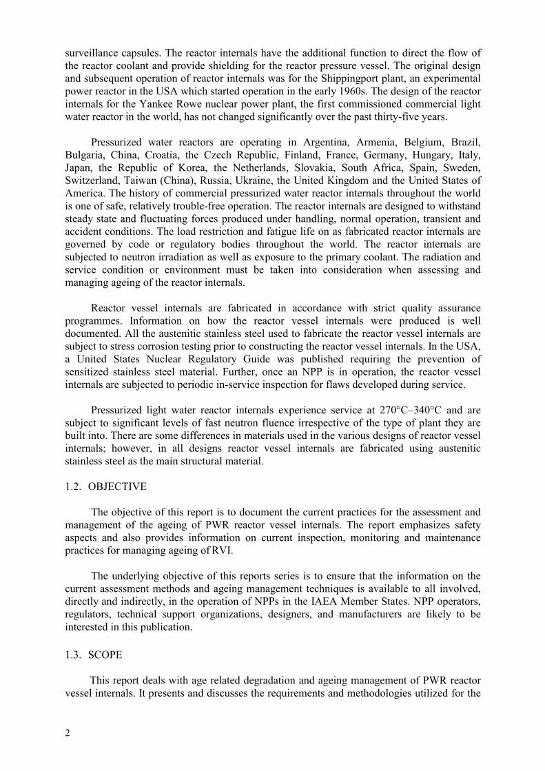
FIG.1. Structural assembly grouping of PWR RVI.
5
2. DESCRIPTION OF REACTOR VESSEL INTERNALS
Section 2.1 provides the overall system description of western type PWR RVI andincludes design features, applicable material specifications and differences among the variousRVI components. Today’s operating PWR RVI were mainly designed and manufactured byWestinghouse, Combustion Engineering, Inc., Babcock & Wilcox Company, MitsubishiHeavy Industries, Ltd, Framatome, and Siemens/KWU. Section 2.2 provides the overallsystem description of Eastern type PWR RVI (WWER) and includes the main design features,applicable material specifications and differences among the 440 MW- and 1000 MW-typeRVI components, designed by OKB Gidropress and manufactured by Izhora Works or Skoda.
2.1. WESTERN TYPE PWR RVI
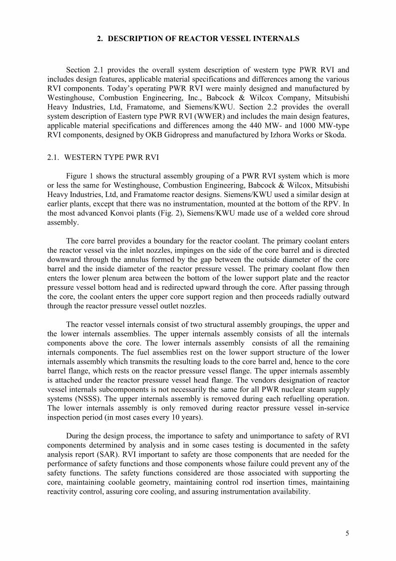
Figure 1 shows the structural assembly grouping of a PWR RVI system which is moreor less the same for Westinghouse, Combustion Engineering, Babcock & Wilcox, MitsubishiHeavy Industries, Ltd, and Framatome reactor designs. Siemens/KWU used a similar design atearlier plants, except that there was no instrumentation, mounted at the bottom of the RPV. Inthe most advanced Konvoi plants (Fig. 2), Siemens/KWU made use of a welded core shroudassembly.
The core barrel provides a boundary for the reactor coolant. The primary coolant entersthe reactor vessel via the inlet nozzles, impinges on the side of the core barrel and is directeddownward through the annulus formed by the gap between the outside diameter of the corebarrel and the inside diameter of the reactor pressure vessel. The primary coolant flow thenenters the lower plenum area between the bottom of the lower support plate and the reactorpressure vessel bottom head and is redirected upward through the core. After passing throughthe core, the coolant enters the upper core support region and then proceeds radially outwardthrough the reactor pressure vessel outlet nozzles.
The reactor vessel internals consist of two structural assembly groupings, the upper andthe lower internals assemblies. The upper internals assembly consists of all the internalscomponents above the core. The lower internals assembly consists of all the remaininginternals components. The fuel assemblies rest on the lower support structure of the lowerinternals assembly which transmits the resulting loads to the core barrel and, hence to the corebarrel flange, which rests on the reactor pressure vessel flange. The upper internals assemblyis attached under the reactor pressure vessel head flange. The vendors designation of reactorvessel internals subcomponents is not necessarily the same for all PWR nuclear steam supplysystems (NSSS). The upper internals assembly is removed during each refuelling operation.The lower internals assembly is only removed during reactor pressure vessel in-serviceinspection period (in most cases every 10 years).
During the design process, the importance to safety and unimportance to safety of RVIcomponents determined by analysis and in some cases testing is documented in the safetyanalysis report (SAR). RVI important to safety are those components that are needed for theperformance of safety functions and those components whose failure could prevent any of thesafety functions. The safety functions considered are those associated with supporting thecore, maintaining coolable geometry, maintaining control rod insertion times, maintainingreactivity control, assuring core cooling, and assuring instrumentation availability.

6
FIG.2. Siemens/KWU RVI design (Konvoi plant).
7
The following RVI components are needed in support of the above safety functions:
(a) Maintaining the core support and/or cooling geometry
– Lower core plate– Lower support forging or casting plate– Lower support columns– Core barrel– Radial keys and clevis inserts– Baffle and former assembly– Core barrel outlet nozzle– Secondary core support– Diffuser plate– Upper support plate assembly– Upper core plate– Upper support columns and guide tubes– Internals holddown spring– Head/vessel alignment pins– Clevis inserts.
(b) Maintaining reactivity control and control rod insertion time
– Rod cluster control assembly (RCCA) control rods– RCCA guide tubes – Upper core plate alignment pins and clevis inserts – Driverods.
(c) Assuring instrumentation availability
– BMI columns and flux thimbles– Upper instrumentation column.
Failure of the following RVI components could prevent the above safety functions:
– Neutron panels/thermal shield– Head cooling spray nozzles– Mixing device.
2.1.1. RVI constituent parts
The reactor core is positioned and supported by the lower internals and upper internalsassembly. The individual fuel assemblies are positioned by fuel pins in the lower and uppercore plates. These pins control the orientation of the core with respect to the lower internalsand upper internals. The lower internals are aligned with the upper internals by the upper coreplate alignment pins and secondarily by the head/vessel alignment pins. The lower internalsare orientated to the vessel by the lower radial keys and by the head/vessel alignment pins.Thus, the core is aligned with the vessel by a number of interfacing components.
RVI constituent parts are classified as either core support structures (CS) or internalsstructures (IS). A core support structure provides support and restraint of the core. Theinternals structures are all other structures within the reactor pressure vessel that are not coresupport structures, fuel assemblies, blanket assemblies, control assemblies, or instrumentation.

8
Lower core plate (CS) and fuel alignment pins
The lower core plate (LCP) is important to safety because it positions and supports thecore and provides a metered control of reactor coolant flow into each fuel assembly.
The LCP is located near the bottom of the lower support assembly, inside the corebarrel, and above the lower support forging. There are fuel pins, typically two per fuelassembly, attached to the core plate, that position the fuel assemblies. The fuel assemblies arepositioned over the four flow holes per assembly which control the amount of flow enteringeach fuel assembly. The AISI Type 304 stainless steel perforated plate is circular and is boltedat the periphery to a ring welded to the ID of the core barrel. The span of the plate is supportedby lower support columns that are attached at their lower end to the lower support plate. Atthe core plate centre, a removable plate is provided for access to the lower head region of thevessel.
Lower support forging or casting (CS)
The lower support forging or casting is important to safety because it provides supportfor the core by reacting against LCP loads transmitted through the lower support columns. Theplate must direct coolant flow from the lower head plenum to the core region. Also, access tothe lower head region of the vessel during field assembly and in-service inspection (ISI) isprovided via a removable plate.
Lower support columns (CS)
The lower support columns are important to safety because they support the LCP andtransmit the loads from the LCP to the much thicker and stiffer lower support forging. Somelower support columns also serve as a guide for the neutron flux thimbles.
The lower support columns separate the LCP and the lower support. The columns reactagainst the core loads acting on the LCP and transmit these loads to the lower support. Thecolumns are attached with threaded fasteners to the LCP and a threaded joint to the lowersupport.
Core barrel (CS)
The core barrel is important to safety, because its primary function is to support thecore. Lateral support for the core is provided at the upper and lower core plate locations and atintermediate positions during a seismic and LOCA event. During a seismic and LOCA event,the core may impact the baffle/former assembly that is supported by the core barrel. Inaddition to the support requirement, the core barrel needs to provide a passageway for thereactor coolant flow. It directs the reactor coolant flow to the core, and after leaving the core itdirects the flow to the outlet nozzles.
The core rests directly on the LCP that is ultimately supported by the core barrel. TheLCP is attached at its periphery to the core barrel ID and supported by lower support columnsthat are attached to the lower support forging. The lower support forging is welded at its edgeto the bottom end of the core barrel.
Radial keys and clevis inserts (CS)
The radial keys and clevis inserts are important to safety because they restrain largetransverse motions of the core barrel but at the same time allow unrestricted radial and axialthermal expansions.
9
The lower core barrel is restrained laterally and torsionally by these uniformly spacedkeys. The radial keys, along with the matching clevis inserts, are designed to limit thetangential motion between the lower end of the core barrel and the vessel. At assembly, as theinternals are lowered into the vessel, the keys engage the keyways of the inserts in the axialdirection. With this design, the core barrel is provided with a support at the farthest extremityand may be viewed as a beam fixed at the top and guided at the bottom. With the radial keyand inserts, the radial and axial expansions of the core barrel are accommodated butcircumferential movement (i.e. rotation) of the core barrel is restricted. The radial keys areattached to the core barrel at the lower support forging level.
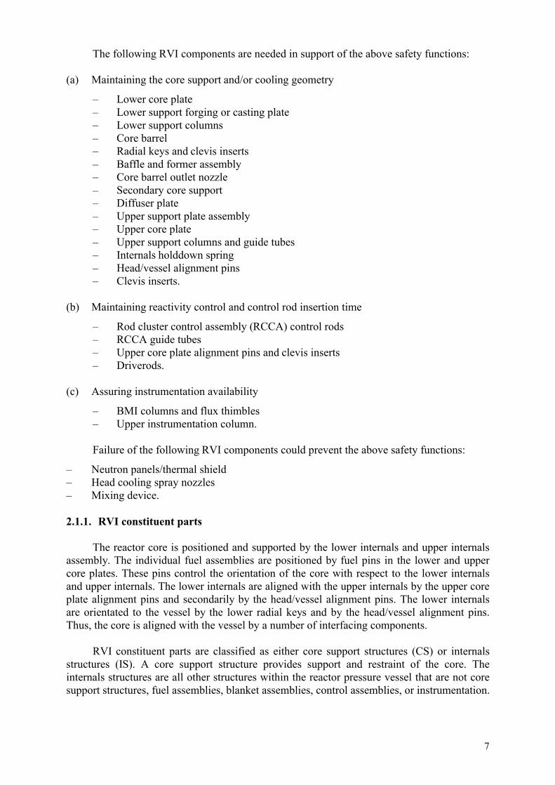
Baffle and former assembly (CS)
The baffle and former assembly (Fig. 3) is important to safety because it provides a highconcentration of the reactor coolant flow in the core region. The baffle and former assembly ismade up of vertical plates called baffles and horizontal support plates called formers. Thebaffle plates are bolted to the formers by the baffle/former bolts, and the formers are attachedto the core barrel ID by the barrel/former bolts.
The baffle and former assembly forms the interface between the core and the core barrel.The baffles provide a barrier between the core and the former region so that a highconcentration of flow in the core region can be maintained.
Core barrel outlet nozzle (IS)
The core barrel outlet nozzles are safety important because they direct the reactorcoolant after it leaves the core, radially outward through the reactor vessel outlet nozzles. Thecore barrel outlet nozzles are located in the upper portion of the core barrel directly below theflange and are attached to the core barrel, each in line with a vessel outlet nozzle face and thevessel outlet nozzle land. The nozzles extend radially from the core barrel to the ID of thevessel and are customized during manufacture to minimize this gap. The size of the gapreduces during heat-up and may go to a small interference at operating temperatures. Thiscomponent is classified as an internal structure, since it does not provide support for the core.
Neutron panels/thermal shield (IS)
Neutron panels or thermal shields are not considered to be safety important because theydo not support or interact with the core. Additional neutron shielding of the reactor vessel isprovided in the active core region by neutron panels or thermal shields that are attached to theoutside of the core barrel. Neutron panels are attached to the OD of the core barrel atstrategically located positions to reduce the fluence on the reactor vessel welds. The thermalshield design provides shielding for the complete 360-degree circumferential sector. It isfastened with bolts and dowels below the outlet nozzles and also near the lower portion of thecore barrel with flexures. At some plants, the thermal shield has been removed.
Secondary core support (IS)
The secondary core support is considered safety important because it maintains integrityof the core following a postulated failure of the core barrel. The function of the secondary coresupport, following a postulated failure and downward displacement of the core barrelsubassembly, is to:
�� Absorb a portion of the energy generated by the displacement and limit the forceimposed on the vessel

10
FIG.3. Baffle and former assembly.

11
�� Transmit and distribute the vertical load of the core to the reactor vessel�� Limit the displacement to prevent withdrawal of the control rods from the core�� Limit the displacement to prevent loss of alignment of the core with the upper core
support to allow the control rods to scram.
Bottom-mounted in-core instrumentation columns (IS) and flux thimbles (IS)
Bottom-mounted in-core instrumentation columns and flux thimbles are not consideredto be safety important because they do not support or interact with the core. The functions ofthese columns are to provide a path for the flux thimbles into the core from the bottom of thevessel and to protect the flux thimbles during the operation of the reactor. There are two typesof bottom mounted in-core instrumentation columns. The cruciform columns extend throughthe flow holes of the lower support forging and attach to the bottom of the LCP. The standardguide columns line up with the lower support columns and are bolted to the bottom side of thelower support. These are line drilled to provide a flux thimble path, and the lower end of thecolumn is counterbored to fit over the vessel conduit penetration. This provides anuninterrupted, protected path for flux thimbles entering the reactor core.
The flux thimble is a long, slender stainless steel sealed tube that passes through thevessel penetration, through the lower internals assembly, and finally extends to the top of thefuel assembly. The flux thimble provides a path for the neutron flux detector into the core andis subjected to reactor coolant pressure and temperature on the outside surface and toatmospheric conditions on the inside.
The flux thimbles remain stationary during reactor operation, with the bullet end of thethimbles positioned slightly above the top of the active fuel. For refuelling, the thimbles areretracted to a point where the bullet tip is below the LCP. For the removal of the lowerinternals assembly, the flux thimbles are pulled out further until the bullet tip is outside of thereactor vessel.
Diffuser plate (IS)
The diffuser plate is not considered to be safety important because it is not the primarysource of flow uniformity. To enhance flow uniformity entering the LCP, some plants employan additional orifice plate called a diffuser plate. This plate is clamped in place by the lowersupport columns between the LCP and lower support plate.
Head cooling spray nozzles (IS)
Head cooling spray nozzles are not considered to be safety important because they donot support or interact with the core. Head cooling spray nozzles are used to adjust the upperplenum coolant temperature by allowing bypass flow at the vessel inlet temperature from thevessel/core barrel downcomer region to flow directly into the upper head plenum. Differentdesigns evolved, so the exact configuration would depend on the production date.
Upper support plate assembly (CS)
The upper support plate assembly is safety important because it supports the guide tubesand the core. The upper support plate assembly is a rigid base that positions and supports theguide tubes and the upper support columns that, in turn, position and support the UCP. Theupper support plate also positions and supports the thermocouple columns and guides. Thereare three models of upper support plate assemblies: (1) a deep beam, (2) top hat, and (3) aninverted top hat.

12
Upper core plate (CS)
The upper core plate (UCP) is safety important because it interacts with the core bypositioning the fuel assemblies and the guide tubes. The UCP positions the upper ends of thefuel assemblies and the lower ends of the control rod guide tubes, thus serving as thetransition member for the control rods during entry and retraction from the fuel assemblies. Italso controls coolant flow when it exits from the fuel assemblies and serves as a boundarybetween the core and upper plenum.
Upper support column (CS)
The upper support columns are safety important because they interact with the core (fuelassemblies). They perform the following functions:
�� Preload fuel assembly and react fuel assembly forces
�� Serve as separation members for the upper support plate and UCP in formation of thecore outlet plenum
�� Position, guide, and support the thermocouples for core outlet water temperaturemeasurement including housing flow-mixing devices.
Guide tube (IS)
The guide tubes (GTs) are safety important because they control the path of the controlrods in and out of the core. Guide tubes are bolted from the top of the upper support plate andare supported at their lower end to the UCP with spring-type pins. They perform the followingfunctions:
�� Provide a straight low-friction path for the control rods into or out of the fuelassemblies.
�� Provide sufficient protection for the control rods when they are withdrawn from the fuelelements to prevent damage due to parallel and lateral coolant flow.
�� Provide a convenient, safe storage place for the control rod drive lines during refuelling.
Upper instrumentation column (IS)
The upper instrumentation columns are not considered safety important. The upperinstrumentation columns provide a passageway and cross-flow protection to the conduits that,in turn, house the thermocouples. The thermocouples are inserted into the top of the upperinstrumentation columns and are routed down through the inside of various support columns.The ends of the thermocouples protrude below the upper support columns so that thetemperature of the coolant exiting the fuel assemblies can be measured.
Mixing device (IS)
The mixing device is not considered safety important. Mixing devices are used withthermocouples to enhance the temperature reading at the core outlet just above the UCP.Mixing devices are not used in all plant designs.
The mixing devices are cast cylinders with four vanes cast on the inside. They arelocated individually on the UCP or full penetration-welded to the upper support columns at allthermocouple locations. They sustain the same loads as the upper support columns exceptwhen individually attached to the UCP.
13
Interfacing components
The interfacing components listed in this section and following sections are consideredsafety important because they basically interact with components that support the core. Thegeneral requirements of the interfacing components are to orient adjacent components withrespect to each other and/or provide support for an adjacent component. These componentsare the lower internals assembly, the upper internals assembly, the fuel and driveline, or thereactor vessel. The UCP alignment pins position the UCP with respect to the lower internalsassembly and provide lateral support to the lower end of the upper internals assembly. Theholddown spring supports the upper internals assembly and holds the lower internals assemblydown. The head and vessel alignment pins align the lower internals assembly and the upperinternals assembly with the vessel. The radial support inserts provide a support surface for theradial support keys.
Upper core plate alignment pin
The UCP alignment pins locate the UCP laterally with respect to the lower internalsassembly. The pins must laterally support the UCP so that the plate is free to expand radiallyand move axially during differential thermal expansions between the upper internals and thecore barrel.
The UCP alignment pins are the interfacing components between the UCP and the corebarrel. The UCP alignment pins are shrunk-fit and welded into the core barrel and the corebarrel bearing pad. The gap sizes between the alignment pins and the matching inserts arecustomized.
Hold down spring
The hold down spring provides a preload to limit the axial motion of the upper andlower internals assemblies and to prevent liftoff of the core barrel flange from the vesselledge. The spring preload also reduces the lateral motion of the upper support plate flange andthe core barrel flange. The hold down spring is required to be designed for operating conditionloads.
The hold down spring, which is a circumferential spring with an essentially rectangularcross-section, is located between the flanges of the upper support plate and the core barrel.The hold down spring is preloaded by a compressive force when the reactor vessel head isclamped in place with the reactor vessel closure studs and nuts. Therefore, the hold downspring is an interfacing component between the upper internals assembly and the lowerinternals assembly.
Head and vessel alignment pins
The head and vessel alignment pins align the upper and lower internals assemblies withrespect to the vessel. The head-vessel alignment pins are located at the outside periphery ofthe core barrel flange at the four major axes. A portion of the pin extends below the corebarrel flange and engages pockets in the reactor vessel to provide alignment of the lowerinternals assembly with respect to the vessel.
Similarly, a portion of the pin extends above the flange and aligns the upper internalsassembly with respect to the vessel. This portion of the pin engages pockets in the reactorvessel head, thus establishing an alignment of lower internals, reactor vessel, upper internals,and reactor vessel head. Minimal clearance is maintained between the pins and the

14
engagement pockets to ensure functional alignment and to allow ease of assembly. Theclearances are designed to prevent thermal loads in the pins during temperature excursionsand to reduce the stress in the pins during horizontal loading of the upper internals.
Radial keys and clevis inserts
The radial keys and clevis inserts provide the interface between the lower internals andthe vessel.
Driveline components
The driveline components are the drive rod and the control rods. The control rods areidentified as the RCCA (rod cluster control assembly). The drive rod and RCCA make up theinterface between the drive mechanism on the reactor pressure vessel head and the guide tubesand fuel.
2.1.2. Materials
Various product forms are used in the manufacture of reactor vessel internals assembliessubcomponents. These various product forms include plates, forgings, rolled rings, andcastings of austenitic stainless steel. The reactor vessel internals assemblies subcomponentsare joined by either welding or bolting the subcomponents together to form a completeassembly. Stainless steels have been used in the manufacture of reactor vessel internalsbecause of their corrosion resistance, toughness, ductility, strength and fatigue characteristicsin pressurized water reactor environment. In western type reactor vessel internals, AISI Type304 and 347 stainless steel or of corresponding designations are used in various product formsin all of the larger internals components, as for example, core barrels, support columns, corebarrel flange, core plates, core support plates, hold down springs, guide tubes and core baffle-former assemblies. Fastener or bolts are fabricated from 304, 347, 316 cold worked, 316Ticold worked stainless steel or Alloy X-750 material. In some western type reactor vesselinternals, Alloy 600 may be used. All materials employed in reactor vessel internals haveestablished fabrication and service histories.
In France, core barrel, core baffles and formers are fabricated with the plates of Type304L steel with a controlled nitrogen content in solution annealed condition. The formerplates have a final thickness of some 40 mm. The core barrel is made with plates of athickness close to 50 mm, rolled and welded.
In the UK, core support structures are constructed from Type 304 austenitic stainlesssteel solution annealed where required core support structure plates and forgings are weldedtogether using a mechanized Tungsten inert gas (TIG) process. The filler metal used is of typeSFA 5.9 Class ER 308L.
In Germany, the materials which are employed are niobium stabilized austeniticstainless steels, solution annealed. Materials most relevant to the internal structures are steelsX6CrNiNb 18-10 (1.4550) and X6CrNiMoTi 17-12-2 (1.4571).
Threaded structural fasteners and bolts from cold worked Type 316 austenitic stainlesssteel are used in French and British reactors internals. In Germany, a cold worked type 1.4571austenitic stainless steel (similar to AISI Type 316 but titanium stabilized) is employed forfasteners.
15
In French reactor internals, several other materials are also used. They are very similarto those of the US reactor internals (forged, cast stainless steel, etc.). Their specifications areidentical to those of similar materials employed in other parts of the reactor, but there is aspecific requirement for the cobalt content, which has to be limited to 0.1% for large enoughpieces (RCC-M G2400).
It is however worthwhile to mention alloy Inconel X-750, which is used for the supportpins of the control rods mechanisms and in former German design for baffle bolts and fuelalignment pins as well. This alloy is solution annealed at 1080°C for 1 hour and is exposed toa precipitation hardening heat treatment for 20 h at 700°C.
Typical reactor vessel internals materials and their chemical composition are given inTables I–IV.
2.2. WWER TYPE RVI
The reactor internals function is to support the core, to hold the fuel assemblies in place,to direct coolant flow, to hold and protect control rods in normal operation conditions andaccident conditions. The reactor internals are designed to ensure cooling of the fuel, to ensurethe movement of control rods under all operating conditions including accidents (up tomaximum DBA with superimposed safe shutdown earthquake loads) and facilitate removal ofthe fuel and of the internals proper following an accident.
Hot and cold leg RPV nozzles are located in WWER reactors at two differentelevations; therefore a horizontal seal separates the cold and hot legs. After passing throughthe core, the hot coolant enters the hot leg nozzles through a perforated part in the top sectionof the core barrel.
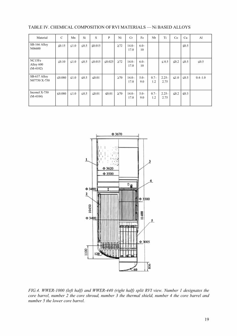
An overall view of the design of WWER-440 and WWER-1000 RVI is given in Fig. 4.For more details, see [7].
The main components of the WWER reactor internals are the core barrel, the coreshroud (core basket for WWER-440) at the level of the core and the block of guide tubes.These components are fixed together and to the reactor vessel in a way, that allows theirwithdrawal, inspection, and partial repair as well as inspection of the reactor pressure vesselinner surface.
The WWER reactor vessel internals are manufactured, assembled and installed in linewith requirements of the respective standards and quality control and assurance procedures.RVI are tested at the manufacturer using vessel and core mock-up as well as during operationfollowing an inspection (control rod movement).
2.2.1. RVI constituent parts
Core barrel
The core barrel supports the core shroud, the block of guide tubes for the drive rods ofthe control and protection system and separates the cold leg from the hot leg.
The core barrel of WWER-440 is a vertical cylinder with maximum diameter of3370 mm and height of 10 960 mm made of 7 cylindrical rings welded together. The wallthickness of the cylindrical rings is between 50 and 80 mm.
16
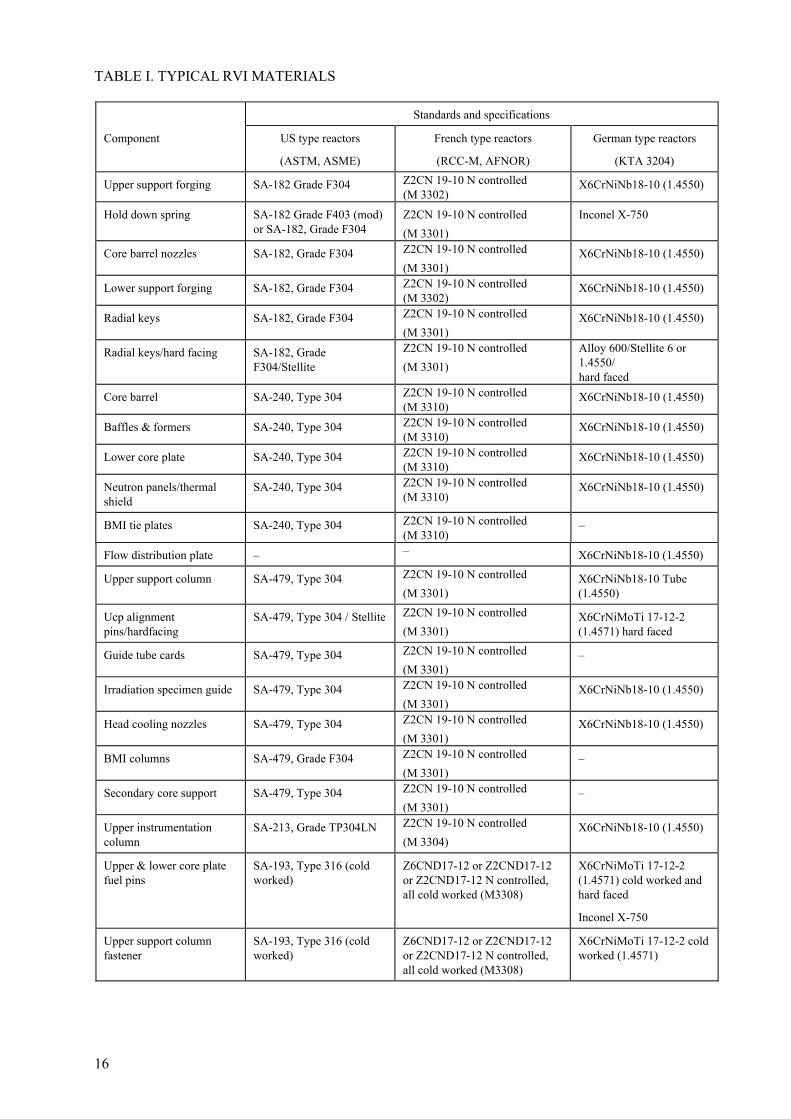
TABLE I. TYPICAL RVI MATERIALS
Standards and specifications
Component US type reactors
(ASTM, ASME)
French type reactors
(RCC-M, AFNOR)
German type reactors
(KTA 3204)
Upper support forging SA-182 Grade F304 Z2CN 19-10 N controlled(M 3302)
X6CrNiNb18-10 (1.4550)
Hold down spring SA-182 Grade F403 (mod)or SA-182, Grade F304
Z2CN 19-10 N controlled(M 3301)
Inconel X-750
Core barrel nozzles SA-182, Grade F304 Z2CN 19-10 N controlled(M 3301)
X6CrNiNb18-10 (1.4550)
Lower support forging SA-182, Grade F304 Z2CN 19-10 N controlled(M 3302)
X6CrNiNb18-10 (1.4550)
Radial keys SA-182, Grade F304 Z2CN 19-10 N controlled(M 3301)
X6CrNiNb18-10 (1.4550)
Radial keys/hard facing SA-182, GradeF304/Stellite
Z2CN 19-10 N controlled(M 3301)
Alloy 600/Stellite 6 or1.4550/hard faced
Core barrel SA-240, Type 304 Z2CN 19-10 N controlled(M 3310)
X6CrNiNb18-10 (1.4550)
Baffles & formers SA-240, Type 304 Z2CN 19-10 N controlled(M 3310)
X6CrNiNb18-10 (1.4550)
Lower core plate SA-240, Type 304 Z2CN 19-10 N controlled(M 3310)
X6CrNiNb18-10 (1.4550)
Neutron panels/thermalshield
SA-240, Type 304 Z2CN 19-10 N controlled(M 3310)
X6CrNiNb18-10 (1.4550)
BMI tie plates SA-240, Type 304 Z2CN 19-10 N controlled(M 3310)
–
Flow distribution plate – – X6CrNiNb18-10 (1.4550)
Upper support column SA-479, Type 304 Z2CN 19-10 N controlled(M 3301)
X6CrNiNb18-10 Tube(1.4550)
Ucp alignmentpins/hardfacing
SA-479, Type 304 / Stellite Z2CN 19-10 N controlled(M 3301)
X6CrNiMoTi 17-12-2(1.4571) hard faced
Guide tube cards SA-479, Type 304 Z2CN 19-10 N controlled(M 3301)
–
Irradiation specimen guide SA-479, Type 304 Z2CN 19-10 N controlled(M 3301)
X6CrNiNb18-10 (1.4550)
Head cooling nozzles SA-479, Type 304 Z2CN 19-10 N controlled(M 3301)
X6CrNiNb18-10 (1.4550)
BMI columns SA-479, Grade F304 Z2CN 19-10 N controlled(M 3301)
–
Secondary core support SA-479, Type 304 Z2CN 19-10 N controlled(M 3301)
–
Upper instrumentationcolumn
SA-213, Grade TP304LN Z2CN 19-10 N controlled(M 3304)
X6CrNiNb18-10 (1.4550)
Upper & lower core platefuel pins
SA-193, Type 316 (coldworked)
Z6CND17-12 or Z2CND17-12or Z2CND17-12 N controlled,all cold worked (M3308)
X6CrNiMoTi 17-12-2(1.4571) cold worked andhard faced
Inconel X-750
Upper support columnfastener
SA-193, Type 316 (coldworked)
Z6CND17-12 or Z2CND17-12or Z2CND17-12 N controlled,all cold worked (M3308)
X6CrNiMoTi 17-12-2 coldworked (1.4571)

17
TABLE I. (cont.)
Standards and specifications
Component US type reactors
(ASTM, ASME)
French type reactors
(RCC-M, AFNOR)
German type reactors
(KTA 3204)
Baffle-barrel-formerfastener
SA-193, Type 316 (coldworked)
Z6CND17-12 or Z2CND17-12or Z2CND17-12 N controlled,all cold worked (M3308)
X6CrNiMoTi 17-12-2 coldworked (1.4571)
Neutron panel bolts SA-193, Type 316 (coldworked)
Z6CND17-12 or Z2CND17-12or Z2CND17-12 N controlled,all cold worked (M3308)
X6CrNiMoTi 17-12-2 coldworked (1.4571)
Guide tube holddown bolts SA-193, Type 316 (coldworked)
Z6CND17-12 or Z2CND17-12or Z2CND17-12 N controlled,all cold worked (M3308)
X6CrNiMoTi 17-12-2 coldworked (1.4571)
BMI bolts SA-193, Type 316 (coldworked)
Z6CND17-12 or Z2CND17-12or Z2CND17-12 N controlled,all cold worked (M3308)
–
BMI thimble tubes SA-213, Type 316 (coldworked), SB-167 (Alloy600)
NC15Fe Alloy 600 (M 4102) –
Guide tube support pins &nuts
SA-193, Type 316 (coldworked) or W SpecA637C01 (X-750)
Inconel X 750 (M 4104) X6CrNiNb18-10 (1.4550) hardfaced
Irradiation specimen guidespring
SB-637, UNS N07750(X-750)
Inconel X 750 (M 4104) –
Clevis insert fastener SB-637, UNS N07750(X-750)
Inconel X 750 (M 4104) –
Flow mixing device SA-351 GR CF8 Z3CN20-09M
(M 3405)
X6CrNiNb18-10 (1.4550)
Lower support casting SA-351 GR CF8 Z3CN20-09M
(M 3405)
–
Clevis insert hardfacing SB-166 (Ni-Cr-Fe)Annealed/Stellite
– –
Weld metal 308 & 308l ASME SCII Part C SFA5.9
SFA 5.9 Class ER 308L SFA 5.9 Class ER 308L

18
TABLE II. CHEMICAL COMPOSITION OF RVI MATERIALS — AUSTENITIC STAINLESS STEELS
Material C Mn Si S P Ni Cr Mo Nb Ti Co Cu N B
SA-182Grade F 304
= 0.08 �2.0 �1.0 � 0.03 �0.040 8.0–11.0
18.0–20.0
– – – �0.05 – –
SA-240Type 304
= 0.08 �2.0 �0.75 �0.03 �0.045 8.0–10.5
18.0–20.0
– – �0.05 �0.10
SA-479Type 304
= 0.08 �2.0 �1.0 �0.03 �0.045 8.0–10.5
18.0–20.0
– – �0.05 �0.10
SA-213Grade TP304LN
= 0.035 �2.0 �0.75 �0.03 �0.040 8.0–11.0
18.0–20.0
– – �0.05 0.10–0.16
Z2CN 19-10N controlled(M 3301 –
M 3303 –M 3304–M 3307–M 3310)
304L
�0.035 �2.0 �1.0 �0.03 �0.040 9.0–10.0
18.5–20.0
– – – �0.10 �100
�0.08 �0.0018
Z3CN 18-10N controlled
(M 3302) 304L
�0.040 �2.0 �1.0 �0.03 �0.040 9.0–11.0
18.5–20.0
– – – � 0.10 �100
�0.08 �0.0018
X6CrNiNb18-10
(1.4550)
�0.040 �2.0 �1.0 �0.02 �0.035 9.0–12.0
17.0–19.0
– � 0.65 – � 0.20 – �0.08
SA-213Grade TP316 cold
worked
= 0.08 �2.0 �1.0 �0.03 �0.040 11.0–14.0
16.0–18.0
– –
SA-193cold worked
Type 316
0.04–0.080
�2.0 �0.75 �0.03 �0.045 10.0–14.0
16.0–18.0
2.0–3.0
– – � 0.25 �0.10 –
Z6CND17-12cold worked
(M 3308) 316
0.03–0.080
�2.0 �1.0 �0.03 �0.035 10.0–14.0
16.0–18.0
2.25–3.00
– – � 0.20 �1.0 – –
Z2CND17-12cold workedN controlled
(M 3308) 316
�0.035 �2.0 �1.0 �0.03 �0.035 11.5–12.5
17.0–18.2
2.25–2.75
– – � 0.10 �1.0 �0.08 –
Z2CND17-12cold worked
(M 3308) 316
�0.030 �2.0 �1.0 �0.03 �0.040 10.0–14.0
16.0–19.0
2.25–2.75
– – � 0.10 �1.0 �0.08 –
X6CrNiMoTi 17-12-2
cold worked(1.4571)
�0.060 �2.0 �1.0 �0.02 �0.035 10.5–13.5
16.5–18.5
2.0 –2.5
– � 0.7 � 0.20 – – –
Z3CN 20-09MN controlled
(M 3302) 304L
�0.040 �2.0 �1.0 �0.03 �0.040 9.0–11.0
18.5–20.0
– – – � 0.10 �100
�0.08 �0.0018
SA-351Grade CF8
�0.080 �1.5 �2.0 �0.04 �0.040 8.0–12.0
17.0–21.0
= 0.50 – – – – – –
TABLE III. CHEMICAL COMPOSITION OF RVI MATERIALS — WELDS
Material C Mn Si S P Ni Cr Mo Nb Ti Co Cu Others
Weld SFA 5.4 /5.9Class ER 308L
�0.030 �2.5 �1.0 �0.03 �0.030 9.0–12.0
18.0–20.0
– – – �0.20 �1.0 Ferrite content5–15%
Weld(1.4576)
�0.035 �2.0 �1.0 �0.03 �0.035 11.5–12.5
17.0–18.2
2.252.75
– – �0.20 �1.0
19
TABLE IV. CHEMICAL COMPOSITION OF RVI MATERIALS — Ni BASED ALLOYS
Material C Mn Si S P Ni Cr Fe Nb Ti Co Cu Al
SB-166 AlloyN06600
�0.15 �1.0 �0.5 �0.015 �72 14.0–17.0
6.0–10
�0.5
NC15FeAlloy 600(M-4102)
�0.10 �1.0 �0.5 �0.015 �0.025 �72 14.0–17.0
6.0–10
� 0.5 �0.2 �0.5 �0.5
SB-637 AlloyN07750 X-750
�0.080 �1.0 �0.5 �0.01 �70 14.0–17.0
5.0–9.0
0.7–1.2
2.25–2.75
�1.0 �0.5 0.4–1.0
Inconel X-750(M-4104)
�0.080 �1.0 �0.5 �0.01 �0.01 �70 14.0–17.0
5.0–9.0
0.7–1.2
2.25–2.75
�0.2 �0.3
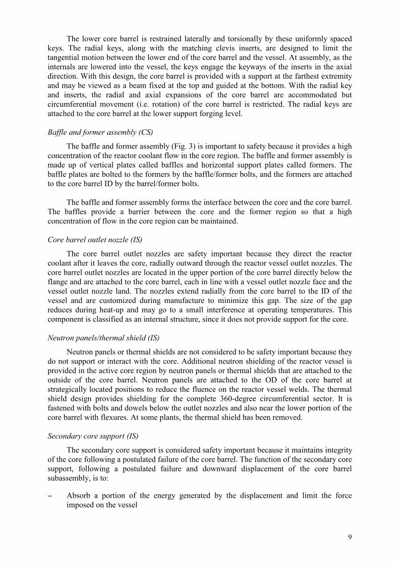
FIG.4. WWER-1000 (left half) and WWER-440 (right half) split RVI view. Number 1 designates thecore barrel, number 2 the core shroud, number 3 the thermal shield, number 4 the core barrel andnumber 5 the lower core barrel.

20
The bottom of the core barrel consists of an upper forged lattice 150 mm thick and alower lattice spacer 50 mm thick. Thirty-seven tubes and a vertical cylinder connect bothlattices.
Guide tubes of these emergency control assemblies, which are welded to the upperlattice, are located inside the tubes at the periphery. They contain the fuel containing part ofthe emergency control assemblies when they are in the bottom position.
The vertical cylinder has a maximum diameter of 3085 mm and a height of about2945 mm. The wall thickness of the 3 cylindrical rings is as a maximum 52.5 mm.
Orifice plates in upper lattice of core barrel bottom create additional resistance of thechannels redistributing coolant flow. This resistance improves hydraulic characteristics ofassemblies, thus making the core less susceptible to any changes (decrease) of coolant flowduring transients.
The orifice plate which rests on positioners along the periphery of core barrel cylindricalpart is fixed by 12 studs against uplift (another 16 studs were added to these vessels in 1989).
On the bottom of each emergency control assembly opening are installed the guide tubesand over them the protection tubes. The tubes are fitted into the openings and welded alongtheir periphery.
The guide and guide tubes on the bottom are protected at their side and from below by aperforated stainless steel sheet shaped as a truncated cone with its broad part up (thickness ofapprox. 10 mm).
The core barrel of WWER-1000 is a vertical cylinder with elliptic perforated bottom(close to the WWER-440 core barrel does not have this item). The core barrel height is 10 510mm, its outer diameter is 3670 mm, the wall thickness of the cylindrical part is 65 mm. Thelower part of the core barrel has supports installed inside as perforated tubes (with narrow 3-mm wide slits). The upper ends of these support tubes are fixed into a distance grid. Theirlower ends are fixed into the perforated bottom of the core barrel.
In its upper part, the core barrel is fixed by 3 elastic tube elements placed between theRPV cover and the barrel flange and by keys at the barrel flanges. During reactor heatup, themiddle part of the barrel locks against the RPV separating belt due to thermal expansion.
In its lower part, the core barrel is fixed by keys welded to the RPV cylindrical shell.
The core barrel and its support structure (the core barrel bottom for WWER-440 andsupport tubes and distance grid for WWER-1000) are important to safety, because theirprimary functions are to confine, fix and support the shroud (basket) and provide apassageway for the reactor coolant flow. They direct the reactor coolant flow to the core, andafter leaving the core, to the outlet nozzles. In addition, the WWER-1000 core barrel supportstructure provides proper horizontal and vertical positioning of the fuel assembly end andsupports the core.
The core barrel keys are important to safety because they restrain large transversemotions of the core barrel while allowing unrestricted radial and axial thermal expansions.

21
Core basket (WWER-440)
The core basket, intended to contain the core, consists of a 300 mm thick plate at thebottom and a cylindrical part consisting of 3 rings with a wall thickness of 30–40 mm. Therings are welded one to another to the bottom plate. The inside surface of the basket is shapedto match the hexagonal boundary of the core. The basket bottom is in fact a support plate ofthe fuel assemblies. It has 312 openings for the fuel assemblies and 37 hexagonal holes for thefuel assemblies of the emergency control assemblies. At the upper part of the basket a limitingring is welded which covers the heads of the peripheral row of operating fuel assemblies andserves as a support of the block of guide tubes. In addition, along the entire height of the coreperiphery there is a reinforced ring made of shaped partitions which is intended to decreaseneutron flux deformation in the fuel assemblies of the external row (the peripheral fuel assemblies) by narrowing the water reflector.
The core basket is erected on core barrel bottom and fixed to it by a plug with 3 studs ofa diameter of 120 mm.
The core basket is important to safety because it provides a reduction of neutron flux tothe RPV, and protects the integrity of the fuel assemblies in the event of pressure differencesinside the RVI.
The core basket support plate is important to safety because it provides properhorizontal and vertical positioning of the fuel assembly end and supports the core.
Core shroud (WWER-1000)
The core shroud in WWER-1000, acting simultaneously as a thermal shield, consists offorged cylindrical shells. The shells are bolted together and their relative position fixed bypins. There are vertical channels inside the shell walls and circumferential grooves on theoutside surface to facilitate cooling of the shroud metal. The height of the WWER-1000 coreshroud is 4070 mm and its external diameter 3485 mm. The inside surface of the shroud isshaped to match the hexagonal boundary of the core. In the original design, irradiationsurveillance containers with RPV materials are placed on the upper edge of the top shell.
In its upper part, the shroud is fastened by keys on the inside surface of core barrel. In itslower part it is fastened by 3 pins on the core barrel distance grid and held down to it by 6threaded tubes. The upper and lower fixing of the shroud restrains motions due to coolantflow while allowing unrestricted radial and axial thermal expansions with respect to the corebarrel.
The core shroud is considered to be safety important because it provides a reduction ofneutron flux to the RPV, and ensures integrity of the fuel assemblies in case pressuredifferences inside the RVI.
Block of guide tubes (WWER-440)
The block of guide tubes of the WWER-440 reactors is held down by the RPV head (theso-called upper block), leans against the upper part (the heads) of the fuel assemblies andtherefore prevents displacement of the core, the core basket and the core barrel bottom in alloperating conditions (spring load, spring blocks in the upper part, fuel assemblies headssprings). The block of guide tubes protects the fuel assemblies, the emergency controlassemblies, the drive rods of the control and protection system and the small diameter tubes ofthe reactor instrumentation system against coolant flow effects.

22
The WWER-440 block of guide tubes consists of upper and lower round plates withpenetrations for coolant and for the guide tubes of the emergency control assemblies. The topand bottom plates are welded together with 9 cylindrical rings and interconnected by 37protective tubes. The bottom one serves as a guide for connection with the basket, while thetop one serves as a support structure for the spring blocks.
The bottom part of the block of guide tubes presses against springs of the fuelassemblies. The upper part of the block of guide tubes consists of a top screen, rings and agirder to which the bundles of the cladding temperature monitoring detectors are attached.
The block of guide tubes is important to safety because it protects fuel assemblies fromlift off, and the emergency control assemblies, the drive rods of the control and protectionsystem, and the small diameter tubes of the reactor instrumentation system against coolantflow dynamic effects.
Block of guide tubes (WWER-1000)
The block of guide tubes of the WWER-1000 reactors is a welded structure consisting of3 plates connected by guide tubes, tubes for in-reactor instrumentation and shells. Control rodsmove inside guide tubes. The block of guide tubes structure maintains the fuel assemblies inthe required position (horizontally and vertically), holds them down and protects the controlrods from the dynamic effects of the coolant flow and consequently from becoming stuck.
The lower support plate is in contact with top heads of the fuel assemblies (springloaded). It is perforated to assure coolant flow to the upper plenum. Perforated upper andmiddle plates and slots in the upper shell support flange provide for coolant circulation underthe reactor head. The lower and middle plates are connected by a perforated shell.
Azimuthal positioning is assured with the help of 3 keys welded to the upper shell andcorresponding slots in the core barrel, as well as with the help of 6 keys welded to the barreland corresponding slots in the lower plate of block of guide tubes. Positioning of the block ofguide tubes allows unrestricted radial and axial thermal expansions with respect to the corebarrel and reactor head.
The overall dimensions of block of guide tubes are: height, 8292 mm, external diameterof lower plate, 3550 mm.
In the original design the surveillance specimens of RPV materials to monitor thermalageing are attached to the inside surface of upper shell.
Guide tubes are safety important because they protect the control rods from the dynamiceffects of the coolant flow and consequently from becoming stuck.
The lower support plate is safety important because it provides positioning for the fuelassemblies and hence, is one of the components assuring core integrity.
2.2.2. Materials
The general information for western type PWR RVI given in Section 2.1.2 also appliesto WWER-type RVI.

23
The main structural material used for RVI in both WWER-440 and WWER-1000reactors is titanium stabilized austenitic stainless steel 08Ch18N10T (equivalent to A-321). Inaddition to this austenitic stainless steel and its niobium stabilized welds, precipitationhardened nickel based alloy ChN35VT is also used. This material is used for studs and istungsten alloyed.
Regarding structural RVI materials, the corresponding code is PNAE G-7-002-87 [8],and national Russian standards GOST 5632, GOST 23304, and GOST 2246.
The specifications for WWER RVI materials are given in Tables V–VII.
TABLE V. TYPICAL RVI MATERIALS
Component Specification Note
Core barrelCore barrel vessel, spacing grid, corebarrel bottom, caps of supports,displacer
08Ch18N10T Sheets, sheet stamped blanks
Keys, nuts, washers, plugs, pins 08Ch18N10T Bar and forgingsSupports, tail pieces of supports, tubes 08Ch18N10T Seamless tubes of improved qualityStuds ChN35VT-VD Bar, vacuum arc refined Ni based alloyCore shroudUpper ring, middle ring, lower ring 08Ch18N10T ForgingsSpacing grids 08Ch18N10T SheetsStuds, nuts, washers, reducers, tailpieces
08Ch18N10T Bars and forgings
Tubes 08Ch18N10T Seamless, high qualityBlock of guide tubesShells, slabs, cones 08Ch18N10T SheetsGrids, discs, flanges, sleeves 08Ch18N10T Bars, forgingsFlanges, rods, tips, keys, bolts, pins 08Ch18N10T Bars, forgings, enhanced mechanical
propertiesTubes 08Ch18N10T Seamless, high qualityWelding materialsArgon arc welding Sv-04Ch19N11M3 Welding wireSubmerged automatic welding Sv-04Ch19N11M3 + flux 0F-6 or
FC-17Welding wire
Electroslag welding Sv-04Ch19N11M3 +flux 0F-6
Welding wire
Manual arc welding EN-400/10TEN-400/10V
Electrode rod, gradeSv-04Ch19N11M3
Wear resistant cladding CN-6L Electrode rod, gradeSv-04Ch19N9M3
TABLE VI. CHEMICAL COMPOSITION OF RVI BASE AND BOLTING MATERIALS
Material C Mn Si S P Ni Cr Ti Al W B Fe Note08Ch18N10T �0.08 1.0–
2.0�0.020 �0.035 9.0–
11.017.0–19.0
�5C�0.6
– – base GOST5632
ChN35VT(VD) �0.12 1.0–2.0
� 0.6 �0.02�0.01
�0.030�0 .025
34–3834–36
14.0-16.0
1.1–1.5
– 2.8–3.5
base GOST5632
GOST23304
Note: Under Material, ‘VD’ indicates a vacuum arc remelted material.

24
TABLE VII. CHEMICAL COMPOSITION OF RVI WELD MATERIALS
Material C Mn Si S P Ni Cr Mo Other Note
EA-400/10T �0.10 1.15–3.10
�0.60 �0.025 �0.030 9.0–12.0
16.8–19.0
2.0–3.5 V: 0.3–0.75
Sv-04Ch19N11M3 �0.06 1.0–2.0 �0.60 �0.018 �0.025 10.0–12.0
18.0–20.0
2.0–3.0 – GOST2246
Note: Under Material, ‘Sv’ refers to wire type filler metal for inert gas shielded or submerged arc welding and ‘EA’ denotes acovered electrode.

25
3. DESIGN BASIS, CODES, STANDARDS AND REGULATIONS
Before the development of ASME Boiler and Pressure Vessel Code [9] requirementsspecifically applicable to reactor vessel internals, the design of reactor vessel internals wasbased on criteria specific to each NSSS vendor. However, most western NSSS vendors usedSection III of the ASME Boiler and Pressure Vessel Code, Subsection NB as a guideline forthe development and establishment of reactor vessel internals system design criteria.Allowable stresses were established consistent with structural components. In the USA, theuse of Subsection NB of the ASME Section III received concurrence for the USNRC. Themethodology used for the establishment of reactor vessel internals system design criteria wasapproved by the ASME Code. Using the methodology, the ASME developed Subsection NGto the ASME Boiler and Pressure Vessel Code, Section III specific to reactor vessel internals.Basically the same design basis applies for PWR RVI in western countries throughout theworld. In France the applicable standard is RCC-M [10]. In Germany, the applicable standardis KTA 3204 [11]. In Japan the applicable standard is MITI notification 501, which is basedon the ASME Code. In Russia, the applicable codes and standards are listed below in Section3.5 (these codes and standards has been also adopted in most other countries operatingWWER reactors).
3.1. REQUIREMENTS IN THE USA
Part 50 of the Code of Federal Regulations, Title 10 (10CFR50) [12] regulatesconstruction of nuclear power plants. Section III of the ASME Code is the industry standardfor construction of nuclear power plant facilities, while Section XI of the ASME Boiler andPressure Vessel Code prescribes in-service inspection requirements, including inspection andevaluation of defects.
Reactor internals design fabrication and installation are covered by rules given inSection III of the ASME Boiler and Pressure Vessel Code, Subsection NG, Core SupportStructures. Core support structures are those structures or parts of structures, which aredesigned to provide direct support or restraint of the core (fuel and blanket assemblies), withinthe reactor pressure vessel. Structures, which support or restrain the core only after thepostulated failure of the core support structures are considered to be reactor internalsstructures. Before Subsection NG was published, Subsection NB of the ASME Code was usedas a guideline for the development of vendor-specific internals system design criteria. Therules for reactor internals design are covered in Article NG-3000.
The rules for reactor internals materials are covered in Article NG-2000. The majority ofreactor internals are fabricated using austenitic stainless, both wrought and castings and nickelbased alloys (Alloy X-750, Alloy 600, etc.). Fabrication and installation of reactor internalsare covered in Article 4000. Pre-service inspection is addressed in both Articles NG-2000 andNG-4000.
Although a large number of PWR reactor internals were designed and fabricated prior tothe publication of Subsection NG, the design philosophies of the NSSS vendors throughoutthe western world were such that the intent of Subsection NG was met.
In the USA in addition to the requirements of the ASME Code, Section III, SubsectionNG, a limited number of regulatory guides and bulletins are relevant to reactor vessel internalscomponents assessment and management of ageing.
26
ASME Boiler and Pressure Vessel Code Section III, Subsection NG
The reactor vessel internals are classified as Safety Class 1, which require more detailedanalysis than Class 2 or 3 components. ASME Section III, Subsection NG, Boiler andPressure Vessel Code, Article NG-3000 which is divided into three subsections covers thedesign of reactor vessel internals. The three subsections of Article NG-3000 are:
– NG-3100 General Design– NG-3200 Design by Analysis– NG-3300 Core Support Structural Design.
Subarticle NG-3100 deals with Loading Conditions specified by the Owner (or hisagent) in the form of an Equipment Specification. The equipment specification identifies theDesign Loading in terms of Design Pressure Difference, Design Temperature, DesignMechanical Loads and Design Stress Intensity Values. The Equipment Specification identifiesthe Design and Operating Conditions.
Subarticle NG-3200 deals with the stresses and stress limits which must be consideredfor the analysis of the component. The reactor vessel internals are designed to withstandsteady state and fluctuating loads produced under handling, normal operating transient andaccident conditions. The equipment specification identifies the operating conditions. In the1974 Edition of Subsection NG, there are four categories entitled:
�� Normal Conditions�� Upset Conditions�� Emergency Conditions and�� Faulted Conditions.
Later code editions clarified this nomenclature but basically retained the same stressallowables. The corresponding new categories are:
�� Service Level A�� Service Level B�� Service Level C�� Service Level D.
Subarticle NG-3300 gives the general design requirements for core support structures.The design of Core support structures must meet the requirements of NG-3100 and NG-3200.However, if there is a conflict between NG-3200 and NG-3300, the requirements of NG-3300shall govern.
System hot functional test
Reactor vessel internals are required to undergo pre-operation testing under hotconditions. Nuclear Regulatory Guide 1.20 establishes guidelines for the pre-operationassessment programme. The system hot functional test is done at the plant site and follows theprimary system hydrostatic test. The reactor vessel internals are installed in the reactor vesselwithout fuel. The coolant temperatures are established by pump heating.
Hot functional tests are conducted only once during the plant life. The hot functional testis conducted at elevated temperature and at a flow rate, which is greater than during normalplant operation due to the absence of fuel assembly resistance. The hot functional tests consistof operation with all loops pumps for a minimum of ten days. The hot functional tests ensuresthat the flow-induced load cycling (vibration) of the reactor vessel internals will be well into

27
the high cycle range of their material fatigue design curves, thus providing assurance that thehigh cycle fatigue usage of the reactor vessel internals will be low throughout the plant designlife.
ASME Boiler and Pressure Vessel Code Section XI
Section XI of the ASME Boiler and Pressure Code is the standard for operation and in-service inspection of nuclear power plant facilities. Examination Category B-N-3 of SectionXI, Subsection IWB, provides requirements for the visual examination of removable coresupport structures. These requirements refer to the relevant conditions defined in IWB-3520.4which include loose, missing, cracked, or fractured parts, bolting, or fasteners. Inspection ofbaffle former bolts would fall under these inspection requirements.
3.2. REQUIREMENTS IN FRANCE
In France, the parts of reactor internals supporting the core and maintaining the fuelelements are classified as ES parts and are designed, constructed and inspected following therules of the Subsection G “Equipements internes du réacteur” of the RCC-M code. Thesubsection G of the RCC-M is similar to the Subsection NG of the ASME code as describedin the previous section.
Allowed materials are given in Subsection G 2000. Rules for design are in Subsection G3000. Construction and welding are done following Subsection G 4000 and inspection andcontrols following Subsection G 5000.
3.3. REQUIREMENTS IN GERMANY
In Germany, the appropriate standards for RVI are at present the safety standards of theNuclear Safety Standards Commission, specifically the KTA-3204. The latest issue is fromJune 1998. This standard shall be applied to the RVI of light water reactors as well as to thetools and equipment, used for the installation and removal of the components.
During the design and manufacturing of RVI for plants built before 1984 these ruleswere covered by specifications related to the project.
Components of the RVI in these standards are categorized in three requirement levels,AS-RE 1 to AS-RE 3, depending on their individual tasks and functions.
One chapter deals with the design (construction) and one with the rules for the stressanalysis for the RVI, which are primary derived from the ASME code. The rules for the RVImaterials and material testing are covered in another chapter. The requirements for thematerials are fixed in special material sheets in the annex. Further chapters containrequirements for the manufacturing and the operational surveillance and testing.
In all the chapters of these standards, the actual German standards and regulations, ase.g. DIN-EN, AD, SEW, VdTÜV guidelines, are to be applied.
3.4. REQUIREMENTS IN JAPAN
In Japan, the structural analysis for RVI is described in MITI notification 501, which isbased on subsection NG in the ASME Code. It should be also noted, that the LBB concept isadopted to the primary piping system.

28
3.5. REQUIREMENTS IN RUSSIA
RVI in Russia are designed and manufactured in line with basic nuclear standards [8,13–17] (earlier designs were developed as per previous issues of these standards, except forWWER-440/230 plants, which were designed in line with industrial standards prior to theestablishement of special nuclear ones).
Quality control and quality assurance procedures are applied during design, manufacture,assembly and installation of the reactor internals in accordance with applicable standards. Thereactor internals are tested at manufacturer using vessel and core mock-ups for each unit as apart of RVI and RPV commissioning.
The design provides for in-service inspection and partial repairs of reactor internals. Theinspection is carried out every four years. The inspection is mainly visual and is focused onthe various fixing and interconnection elements. After inspection of the guide tube block andits insertion into the reactor, the control rod movement is tested within the working range.
Reactor internals are designed to withstand various operating regimes. Following amaximum design basis accident at nominal power with superimposed SSE loads, the reactorinternals design provides for emergency reactor shutdown, residual heat removal and corewithdrawal. This has been verified and supported by experimental investigations.
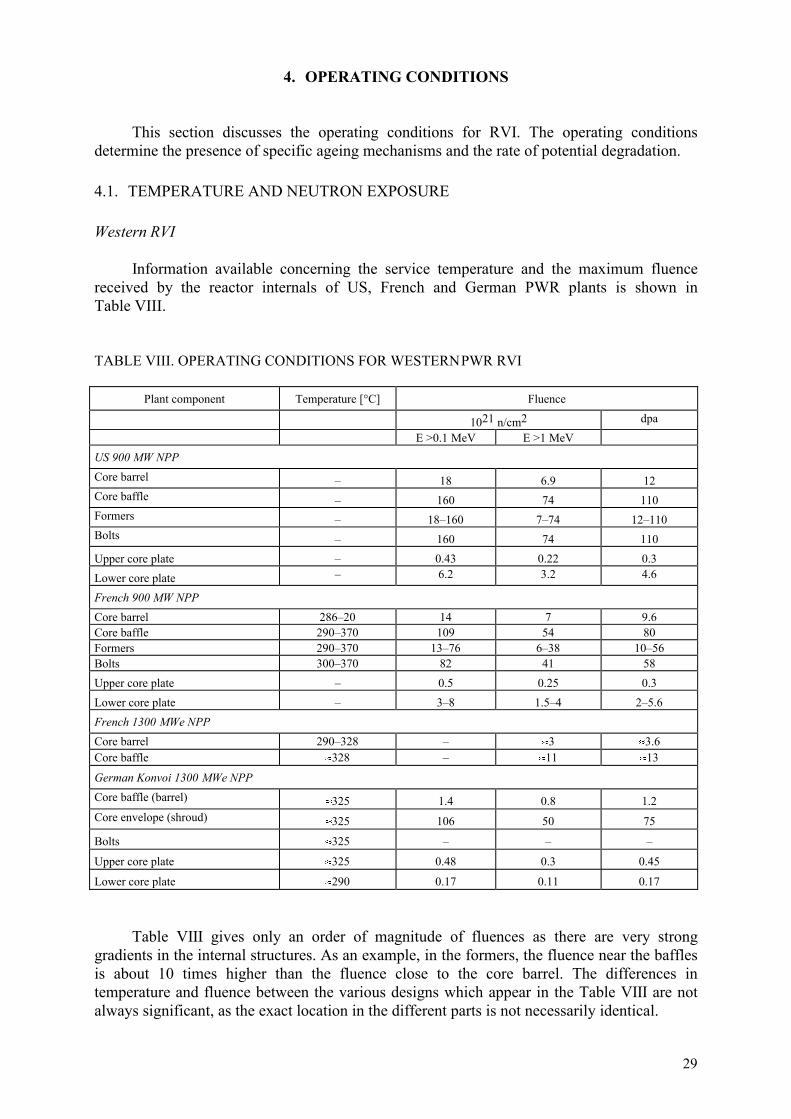
29
4. OPERATING CONDITIONS
This section discusses the operating conditions for RVI. The operating conditionsdetermine the presence of specific ageing mechanisms and the rate of potential degradation.
4.1. TEMPERATURE AND NEUTRON EXPOSURE
Western RVI
Information available concerning the service temperature and the maximum fluencereceived by the reactor internals of US, French and German PWR plants is shown inTable VIII.
TABLE VIII. OPERATING CONDITIONS FOR WESTERN PWR RVI
Plant component Temperature [°C] Fluence
1021 n/cm2 dpaE >0.1 MeV E >1 MeV
US 900 MW NPPCore barrel – 18 6.9 12Core baffle – 160 74 110Formers – 18–160 7–74 12–110Bolts – 160 74 110Upper core plate – 0.43 0.22 0.3Lower core plate – 6.2 3.2 4.6
French 900 MW NPPCore barrel 286–20 14 7 9.6Core baffle 290–370 109 54 80Formers 290–370 13–76 6–38 10–56Bolts 300–370 82 41 58Upper core plate – 0.5 0.25 0.3Lower core plate – 3–8 1.5–4 2–5.6French 1300 MWe NPPCore barrel 290–328 – �3 �3.6Core baffle �328 – �11 �13
German Konvoi 1300 MWe NPPCore baffle (barrel)
�325 1.4 0.8 1.2Core envelope (shroud)
�325 106 50 75
Bolts �325 – – –
Upper core plate �325 0.48 0.3 0.45
Lower core plate �290 0.17 0.11 0.17
Table VIII gives only an order of magnitude of fluences as there are very stronggradients in the internal structures. As an example, in the formers, the fluence near the bafflesis about 10 times higher than the fluence close to the core barrel. The differences intemperature and fluence between the various designs which appear in the Table VIII are notalways significant, as the exact location in the different parts is not necessarily identical.

30
There are also relatively large uncertainties on the temperature reached due to the factthat � heating is not always taken into account in the same manner.
The data for the 3 loops in the 900 MWe type reactors are based on 32 effective fullpower years of operation at 2785 MWth.
The number of displacements per atom is estimated using an average cross section of600 barns (for E >0.1 MeV) for the baffle plate, which leads to: 1 dpa �6.10–22 � fluence(E >0.1 MeV, n/cm2).
The neutron flux in fact varies with the azimuth angle in the core and along the baffles;for a 3 loop 900 MWe reactor, the maximum value of flux on the baffles is obtained for anazimuth around 13°. The ratio of the maximum flux over the flux at azimuth 0° is equal toabout 2. For the core barrel, the maximum neutron flux is obtained in the azimuth range of 0°to 13° and the minimum neutron flux is close to the azimuth 45° with a factor of about 10between the maximum and the minimum flux for E >0.1 MeV.
Operating conditions for the French 4-loop 1300 MWe reactor are based on 32 effectivefull power years of operation at 3817 MWth. In the 4-loop 1300 MWe reactor the maximumfluence is reached at azimuth 45° for the barrel. The variation between the minimum flux andthe maximum flux on the barrel is equal to a factor of about 5. The estimation of thetemperature of operation of the different parts are also indicated and range between 286°C and370°C.
The operating conditions for the Siemens/KWU Konvoi 1300 MWe reactor and for 32equivalent full power years lifetime are also summarized in Table VIII. Normal servicetemperature varies between 290°C and 325°C, with a peak at 370°C due to gamma heating.All components are subject to static and cyclic loading and must withstand additional loadingarising from accident conditions.
WWER RVI
Information available concerning the service temperature and the maximum fluencereceived by the reactor internals of WWER reactors is given in Table IX.
TABLE IX. OPERATING CONDITIONS FOR WWER RVI
Plant component Temperature[°C]
Fluence
1021 n/cm2
E >0.5MeV
dpa
WWER-440Core basket 269–298 20Core barrel outer surface 269–298 2WWER-1000Core shroud (thermal shield) 290–320 45 100Core barrel 290–320 6Block of guide tubes 290–320 0.065
31
The fluence values for WWER-440 RVI are estimated from the calculated maximumend of design life fluence for the inner surface of the RPV. The employment of dummy fuel(shielding) elements or low leakage core, which is used in most of these plants, lowers thesevalues.
The WWER-1000 core baffle fluence value is based on 30 effective full power years.
4.2. PRIMARY COOLANT CHEMISTRY SPECIFICATIONS
Western RVI
The important parameters of the PWR primary coolant chemistry are the boric acid,lithium hydroxide, and hydrogen concentrations, and the resulting pH level. A minimum hightemperature (~300°C) pH of 6.9 (pH300 = 6.9) is required to avoid heavy crud deposits on fuelrods, which can cause accelerated corrosion of fuel rod cladding and increased radiationfields. Some test results show that operation at pH300 of 7.4 results in less crud deposits thanoperation at 6.9. For current PWR operation, the typical range of pH300 is 6.9 to 7.4. ThepH300 for most of the Electricité de France (EDF) plants is 6.9, and the pH is fixed at 7.2 if thecycle duration is 18 months.
Boron is added in the form of boric acid (H3BO3) as a neutron absorber for reactivitycontrol. The boric acid concentration is changed throughout a reactor cycle to compensate forother changes in reactivity and is not varied independently. The boron levels are relativelyhigh (1000 to 2000 ppm) at the beginning of the fuel cycle. Then, they are gradually reducedby 100 ppm/month. The concentration of lithium hydroxide (LiOH) is co-ordinated with theboric acid concentration to achieve the desired pH of approximately 6.9 or higher at operatingtemperature. At the beginning of the fuel cycle, the typical lithium level is about 4 ppm for aboron level of 2000 ppm, and is then reduced as the boron level decreases.
Hydrogen is added to the primary coolant to suppress the buildup of oxygen fromradiolysis. A hydrogen concentration of 25–50 cm3/kg has typically been used. Recent EPRIsponsored studies indicate that increasing the hydrogen concentration in the primary coolantraises the rate of primary water stress corrosion cracking (PWSCC). Consequently, EPRI isencouraging utilities to maintain hydrogen concentrations near the low end of the specifiedrange (i.e. 25–35 cm3/kg).
The Revision 2 of the EPRI guidelines for PWR primary coolant system water chemistryare listed in Table X. EPRI is also about to issue a third revision of their guidelines, whichwill include the following changes: sulphate is added as a control parameter (50 ppb); theAction Level 1 for chlorides and fluorides will be 50 ppb, each; and the limitation onhydrogen control at 25–50 cc/kg will be removed for plants with steam generators susceptibleto PWSCC. Also, there are some minor changes to the pH optimization principles, and theLevel 1 definition. (The Level 1 value is now the value outside of which data or engineeringjudgement indicates that long term system reliability may be affected, thereby warranting animprovement of operating practices.)
WWER RVIThe WWER primary reactor coolant chemistry is a reducing, weak alkaline chemistry
treated with the addition of ammonia, potassium, and boric acid. The allowable at power pHand dissolved hydrogen, oxygen, ammonia, chloride, fluoride, iron, oil, copper, and boric acidconcentrations are listed in Table XI for the WWER-440 plants with corrosion resistantstainless steel cladding on the inside surface of the reactor pressure vessel, the WWER-440plants without reactor pressure vessel cladding, and the WWER-1000 plants.
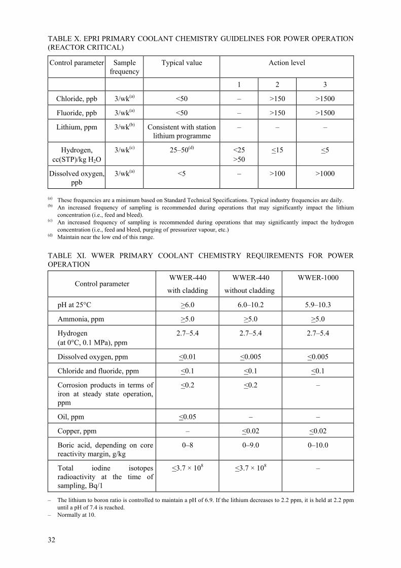
32
TABLE X. EPRI PRIMARY COOLANT CHEMISTRY GUIDELINES FOR POWER OPERATION(REACTOR CRITICAL)
Control parameter Samplefrequency
Typical value Action level
1 2 3
Chloride, ppb 3/wk(a) <50 – >150 >1500
Fluoride, ppb 3/wk(a) <50 – >150 >1500
Lithium, ppm 3/wk(b) Consistent with stationlithium programme
– – –
Hydrogen,cc(STP)/kg H2O
3/wk(c) 25–50(d) <25>50
<15 <5
Dissolved oxygen,ppb
3/wk(a) <5 – >100 >1000
(a) These frequencies are a minimum based on Standard Technical Specifications. Typical industry frequencies are daily.(b) An increased frequency of sampling is recommended during operations that may significantly impact the lithium
concentration (i.e., feed and bleed).(c) An increased frequency of sampling is recommended during operations that may significantly impact the hydrogen
concentration (i.e., feed and bleed, purging of pressurizer vapour, etc.)(d) Maintain near the low end of this range.
TABLE XI. WWER PRIMARY COOLANT CHEMISTRY REQUIREMENTS FOR POWEROPERATION
Control parameterWWER-440
with cladding
WWER-440
without cladding
WWER-1000
pH at 25°C >6.0 6.0–10.2 5.9–10.3
Ammonia, ppm >5.0 >5.0 >5.0
Hydrogen(at 0°C, 0.1 MPa), ppm
2.7–5.4 2.7–5.4 2.7–5.4
Dissolved oxygen, ppm <0.01 <0.005 <0.005
Chloride and fluoride, ppm <0.1 <0.1 <0.1
Corrosion products in terms ofiron at steady state operation,ppm
<0.2 <0.2 –
Oil, ppm <0.05 – –
Copper, ppm – <0.02 <0.02
Boric acid, depending on corereactivity margin, g/kg
0–8 0–9.0 0–10.0
Total iodine isotopesradioactivity at the time ofsampling, Bq/1
<3.7 × 10⁸ <3.7 × 10⁸ –
– The lithium to boron ratio is controlled to maintain a pH of 6.9. If the lithium decreases to 2.2 ppm, it is held at 2.2 ppmuntil a pH of 7.4 is reached.
– Normally at 10.

33
5. AGEING MECHANISMS
This section describes the ageing mechanisms that can affect PWR RVI and evaluatesthe potential significance of the effects of these mechanisms on the continued performance ofsafety functions of the RVI throughout the plant service life.
Ageing mechanisms are specific processes that gradually change characteristics of acomponent with time and use. Ageing degradation are those cumulative changes that canimpair the ability of a component to function within acceptance criteria. Service conditionsoutside prescribed limits, which are caused by design, fabrication, installation, operation, andmaintenance errors, can accelerate the rate of degradation.
Evaluation of ageing mechanisms is based on PWR service experience, pertinentlaboratory data, and relevant experience from other industries. The following ageingmechanisms will be reviewed and assessed for relevance to RVI:
�� embrittlement;�� fatigue;�� corrosion;�� radiation induced creep, relaxation and swelling;�� mechanical wear.
The process for evaluation of an age related degradation mechanism relevant to thecontinued performance of an RVI important to safety leads to one of two possibleconclusions:
�� the ageing degradation is potentially significant to the extent that plant specificevaluation to manage ageing is required; or
�
�� the ageing degradation does not significantly impair the ability of the RVI to perform itsintended safety function.
5.1. EMBRITTLEMENT
There are two types of embrittlement which could affect PWR vessel internalcomponents. These are irradiation embrittlement, which may affect core region internals, andthermal ageing embrittlement, which may affect the cast stainless steel parts and partsmanufactured from martensitic stainless steel.
5.1.1. Description of irradiation embrittlement
Neutrons produce energetic primary recoil atoms which displace large numbers of atomsfrom their crystal lattice positions by a chain of atomic collisions. The number of neutronsbombarding a given location is traditionally measured by the fluence (n/cm2 withE >1.0 MeV). A more recent neutron damage exposure measure is displacements per atom(dpa), which accounts for a wider neutron energy spectrum than the fluence. The fluence ordpa provide part of the information needed to assess irradiation embrittlement.
Wrought austenitic stainless steels do not exhibit the sharp ductile to brittle transitionbehaviour characteristic of low alloy and carbon steels. Rather, toughness losses due to

34
irradiation tend to accumulate with increasing fluence and saturate at levels >1 × 10²¹ n/cm2.Until recently, there was little information available to quantify the effects of irradiationembrittlement on RVI. New information describes the results of a fracture toughness studyperformed on irradiated Type 304 stainless steel reactor internal material taken from operatingBWRs with fluences ranging from 1 � 1021 to 6 � 1021 n/cm2, (E >1 MeV). This studyconfirmed a fracture toughness saturation level of 55 MPa�m for all fluences considered andcan be directly applied to the evaluation of highly irradiated RVI. Available information/datafrom the results of fracture toughness studies performed on irradiated Type 304, 316 CW and347 stainless steel reactor internal material taken from operating PWRs with fluences as highas 2 � 1022 n/cm2 (E >0.1 MeV) shows high fracture toughness values for all fluencesconsidered and can be directly applied to the evaluation of highly irradiated RVI.
Although resistance to crack propagation in internals materials decreases withincreasing neutron fluence, integrity of stainless steel RVI can be effectively assessed usingfracture mechanics analyses. This will, however, require a detailed finite element analysis anda material database that is sufficient to provide the crack growth rates and the fracturetoughness for the materials of interest.
5.1.2. Description of thermal ageing embrittlement
Thermal ageing embrittlement is a time and temperature dependent degradationmechanism. It is caused by the thermally activated movement of lattice atoms over a long timeperiod, a process which can occur without external mechanical load. Changes in materialproperties (e.g. a decrease in ductility and toughness and an increase in strength properties andhardness) are the consequence of these diffusion processes. The significant parametersresponsible for these ageing processes are:
�� temperature;�� material state (microstructure);�� time.
Susceptible to this kind of mechanisms are cast stainless steels, to a lesser extent weldmetal and some Cr rich martensitic steels. Several research projects funded by the USNRC,EPRI, George Fisher Limited of Switzerland, and a consortium of Westinghouse, Framatomeand EDF have evaluated mechanical property degradation which results from thermal ageingembrittlement in typical cast duplex stainless steel materials [18].
Thermal ageing embrittlement of cast stainless can lead to precipitation of additionalphases in the ferrite, e.g., formation of Cr-rich �–prime, phase by spinoidal decomposition;nucleation and growth of �-prime; precipitation of a Ni- and Si-rich phase, M23 C6 carbidesand growth of existing carbides at the ferrite/austenitic phase boundaries. Cast duplexstainless steel used in the piping of primary pressure boundary can be susceptible to thermalageing embrittlement at operating temperatures, i.e., 290ºC–325ºC of NSSS. Thermal ageingembrittlement of cast duplex stainless steel at these temperatures can cause an increase in thehardness and tensile strength and a decrease in ductility, impact strength and fracturetoughness of the material. The susceptibility of ASTM A-351 grades of cast stainless steel tothermal ageing embrittlement is a function of the ageing temperature, time at temperature andmaterial composition including ferrite content.
All the cast duplex stainless steel reactor internals components are made using CF-8 orCF-8A. ASTM A-351 Grades CF-3, CF-3A, CF-8, CF-8A, and CF-8M are used in the piping

35
of the primary pressure boundary. The Mo-bearing CF-8M is the most susceptible cast duplexstainless steel to thermal ageing embrittlement. The temperature at which CF-8M issusceptible to thermal ageing embrittlement decreases with Mo content. Non Mo bearing castaustenitic stainless steel, used in the reactor internals are much less susceptible to thermalageing embrittlement. Based upon the available data on thermal ageing embrittlement of CF-8materials, thermal ageing embrittlement is a non-significant degradation mechanism.
For reasons of stress relieving after welding, some parts of the internals are heat treatedafter welding in Siemens/KWU designed RVI. The heat treatment temperature is chosen to be580°C +10°C/–20°C to avoid any impact on the material properties of the wrought austeniticstainless steels and the weld metal, but has been 700°C in the past, a temperature at which theformation of sigma-phase from the delta-ferrite and the respective influence on the materialproperties cannot be ignored.
5.1.3. Significance of embrittlement
Embrittlement, either due to irradiation or thermal effects, does not directly causecracking. However, the margin of a material to resist propagation of cracks due to other causessuch as fabrication, fatigue or SCC is reduced. The significance of embrittlement for a givencomponent depends on the probability of cracking, and the loading of the component. Forcracked components, a fracture mechanics evaluation of material that has been exposed tohigh neutron fluence should be performed to assure crack stability on a component specificbasis.
Thermal ageing embrittlement is not a significant degradation mechanism for RVI madefrom wrought steel or Ni-Cr-Fe because these materials are not susceptible to the mechanismor the stress levels are not of sufficient magnitude to cause cracking irrespective of the deltaferrite content.
In the case of RVI component parts heat treated at 700°C for stress relieving asmentioned above, plant specific evaluations and irradiation surveillance programmes haveshown that there is no significant ageing effect to be considered for the plant life.
5.2. FATIGUE
5.2.1. Description
Fatigue is defined as the structural deterioration that occurs as a result of repeatedstress/strain cycles caused by fluctuating loads and temperatures. After repeated cyclic loadingof sufficient magnitude microstructural damage can accumulate, leading to macroscopic crackinitiation at the most highly affected locations. Subsequent continued cyclic loading can leadto the growth of the initiated crack.
Fatigue behaviour is related to a variety of parameters, such as stress range, mean stress,cycling frequency, surface roughness and environmental conditions. Cracks initiate at stressconcentrations such as geometric notches and surface defects. Fatigue crack initiation curvesindicate how many stress cycles it takes to initiate fatigue cracks in components. These curvesare materials related and indicate the allowable number of stress cycles for applied cyclicstress amplitudes. Design curves for RPV materials are given in ASME Section III,Appendix I or respective national standards such as KTA 3204 or RCC-M.

36
Environment can significantly influence fatigue crack initiation. Environmentallyassisted fatigue, often referred to as corrosion fatigue, must be considered when dealing withcomponents in the PWR environment.
There are three sources of fatigue significant to the PWR. These are system cycling,thermal cycling and flow induced vibration.
System cycling
System cycling refers to changes in the reactor system, which cause variations inpressure and temperature. Examples of system cycling are startup, shutdown, scram andsafety/relief valve blowdown. System cycling was the best understood source of fatigue duringthe time of vessel design.
Many vessel components were designed against system cycling fatigue crack initiation,using conservative amplitudes and frequencies of normal and upset loading cycles, togetherwith the fatigue design curves of the ASME Code, Section III, Appendix I. Although thedesign process for internals considered system cycling fatigue in a less formalized manner,operating experience to date demonstrates that consideration of system cycling in the internalsdesign process was adequate. The few documented cases of RVI fatigue failures have beenattributed to other fatigue sources.
Thermal cycling
Fatigue thermal cycling may occur due to temperature fluctuations. Temperaturetransients during operation can cause local or global temperature gradients, resulting inthermal cycling at the interface of material and environment. Smooth and sharp temperaturetransients result in slow or rapid thermal cycling, both being a source for accumulation offatigue usage. Causes for smooth transients are generally start up and shutdown procedures orload following operation modes. Connections and disconnection of systems, ECCS waterinjection, and leaking of hot or cold water through untight valves may result in rapid thermalcycling (e.g. thermal shock). The effect of both is ageing of material in terms of low cyclefatigue (slow cycling), or high cycle fatigue (rapid cycling).
Flow induced vibration
Flow induced vibration is caused when coolant flowing past a component sheds vorticeswhich create cyclic loads. These loads generally occur in a frequency range up to about 20 Hz,leading to the expectation that flow induced vibration cycles accumulate early in operation,probably during pre-operation tests. However, it is possible that some modes of flow inducedvibration are associated with a particular operating mode, which occurs infrequently.
5.2.2. Significance of fatigue
Fatigue life estimates includes both crack initiation and crack propagation. Crackinitiation is estimated by determining the fatigue usage at a specific location that results fromeither actual or design basis cyclic loads. Time to initiation can be predicted only if thesequence of the applied loads and recurrence frequency is well known. Such estimates areuncertain if the cyclic loading is random.
ASME Code Section III fatigue analyses are performed to satisfy design requirementsand are not normally the best estimate of actual fatigue usage. The conservatisms applied tothe laboratory fatigue data base and design-basis transients are substantial. The effects of

37
environment and high cycle thermal and mechanical loads may not have been explicitlyconsidered, so the service duty may be higher than reported.
Fatigue damage is significant for some RVI components (bolts and pins) based oncracking incidents reported in service and because of the component design bases. Someinternals were designed against fatigue crack initiation using conservative amplitudes andrecurrence frequencies for normal and upset loading cycles, together with the fatigue designcurves of the ASME Code, Section III, Appendix I. Typically, fatigue usage factors are lessthan 0.10. The number of loading cycles considered during design and the conservatism of thecyclic amplitudes in combination with low fatigue usage factors should be sufficient to justifycontinued operation.
In the case of most internals components the stress and cycling ranges are such thatcyclic analysis is not required per ASME Code Section III NB-3200. This is confirmed bydesign calculations, startup test measurements and service experience. Due to an absence ofsignificant cyclic stress, fatigue is not significant for other RVI components important tosafety.
5.3. CORROSION
Corrosion is the reaction of a substance with its environment that causes a detectablechange which can lead to deterioration in the function of the component or structure. In thepresent context, the material is steel and the reaction is usually an electrochemical reaction.
The appearance of corrosion is governed by the so-called corrosion system consisting ofthe metal and the corrosive medium (the environment) with all the participating elements thatcan influence the electrochemical behaviour and the corrosion parameters. The variety ofpossible chemical and physical variables leads to a large number of types of corrosion:
�� corrosion without mechanical loading (general corrosion and local corrosion attack,selective corrosion attack as e.g. intergranular corrosion);
�� corrosion with mechanical loading (stress corrosion cracking, corrosion fatigue) andsynergistic effects of neutron irradiation (irradiation assisted stress corrosion cracking);
�� flow induced corrosion attack (e.g. erosion corrosion).�
During the electrochemical processes, the metal ions dissolve in liquid electrolyte(anodic dissolution) and hydrogen is produced. This is the process of material loss andcreation of corrosion products. When mechanical stresses or strains are also present, theanodic dissolution of the metal can be stimulated, protection layers (oxide layers) can ruptureor hydrogen interaction with the metal (absorption) can be promoted which can producesecondary damage. The combined action of a corrosive environment and mechanical loadingcan cause cracking even when no material degradation would occur under either the chemicalor the mechanical conditions alone.
Water chemistry control during operation, as well as during shutdown, is very importantwith respect to avoiding corrosion problems. Thus the content of all additives has to becarefully monitored and the ingress of impurities has to be strictly avoided, e.g. during stand-still periods and maintenance work. The water chemistry regimes which are used in theprimary coolant circuits of the various types of reactors and which have proven effective arepresented in Tables X and XI of this report.

38
5.3.1. General corrosion
5.3.1.1. Description
General corrosion is typically characterized by an oxidizing reaction, which occursuniformly over a material surface. This reaction causes a thinning of the surface, andcorrosion proceeds until the surface fails by localized penetration or insufficient cross-sectional area to support a load. However, PWR internals are made from austenitic steel withvery low corrosion rates in the PWR environment.
5.3.1.2. Significance of general corrosion
Evaluations have established that general corrosion of austenitic RVI is not a significantageing mechanism. These conclusions are based on the very low general corrosion rates whichhave been experienced in PWR operating plants for all RVI materials. For steel 08Ch18N10Twhich is used for WWER 440 and WWER 1000 RVI, the general corrosion rate has beeninvestigated during 30 years of operation in primary coolant water with temperature up to300°C and the results showed that the corrosion rate does not exceed 0.1 mm.
5.3.2. Stress corrosion cracking
Stress corrosion cracking (SCC) is the term given to crack initiation and subcriticalcrack growth of susceptible alloys under the influence of tensile stress and a “corrosive”environment. SCC is a complex phenomenon driven by the synergistic interaction ofmechanical, electrochemical and metallurgical factors. There are two forms of SCC, whichcan proceed through a material in either of two modes: intergranular (along the grainboundaries) or transgranular (through the grains). Sometimes the modes are mixed or themode switches from one mode to the other. Intergranular stress corrosion cracking (IGSCC)and transgranular stress corrosion cracking (TGSCC) often occur in the same alloy, dependingon the environment, the microstructure, or the stress/strain state. Stainless steel castings andwelds containing high levels of delta ferrite are unlikely to experience SCC. SCC usuallyproceeds perpendicular to the tensile stress. Cracks also vary in degree of branching orformation of satellite cracks. Most ferritic and duplex stainless steels (stainless steel castingsand welds containing high levels of delta ferrite) are either immune or highly resistant to SCC.
Perhaps the most critical factor concerning SCC is that three conditions necessary forproducing SCC must be simultaneously present. The elimination of any one of these threefactors or the reduction of one of these three factors below some threshold level eliminatesSCC. The three necessary conditions for SCC are:
�� corrosive environment.�� tensile stress;�� susceptible material.
5.3.2.1. Intergranular stress corrosion cracking
IGSCC usually appears like brittle material behaviour, since the crack propagates withlittle or no attendant macroscopic plastic deformation. Many alloys are susceptible to IGSCCin at least one environment. However, IGSCC does not occur in all environments, nor does anenvironment that induces IGSCC in one alloy necessarily induce IGSCC in another alloy.

39
Influence of environment
Two major parameters influence IGSCC. These are water conductivity andelectrochemical potential (ECP). The greatest benefits with respect to preventing IGSCC areattained when both water conductivity and ECP are controlled. Crevices significantly increasethe probability for SCC due to the highly aggressive local environment that may form withinthe crevice.
The PWR coolant is a high purity electrolyte. Although pure water is a low conductingmolecular liquid, it conducts electricity due to the presence of hydrogen (H+) and hydroxide(OH–) ions that result from ionization of a small fraction of the water molecules. It must benoted that even the theoretically lowest conductivity level may not prevent IGSCC in thenormal water chemistry environment since the presence of other ionic species in the solutionincrease conductivity and thereby the probability for corrosion.
Electrochemical potential is a thermodynamic measure of the tendency of a material toundergo a corrosion reaction under certain fixed conditions. Radiolysis of the water passingthrough the core results in large concentration of H2, O2, H2O2 and several other free radicals.
In the PWR coolant, the level of oxidizing species (i.e., oxygen and hydrogen peroxide)primarily controls the ECP of all structural materials. For PWR the ECP of the stainless steelis lower than –230 mV (SHE). When the ECP of stainless steel is lower than –230 mV (SHE),IGSCC of thermally sensitized stainless steel is not possible.
Influence of stress
There are three primary sources of tensile stresses for RVI: these are fabrication inducedstresses, primary stresses, and secondary stresses. Fabrication stresses consist of stressesintroduced during manufacture and installation (i.e., fit up and assembly in the shop or fieldplus those introduced by machining or forming operations and welding). As for weld residualstresses, abusive grinding can produce surface residual stresses near or above the yield pointof the material. Service related primary stresses, including mechanical and pressure loadstresses, may also be as high as the yield stress at constraints in an assembly. Corrosionproduct stress may also play an important role in crack propagation. Secondary stresses suchas thermal transient stresses can also be very high.
The material may exhibit a threshold stress intensity factor, KISCC, below which IGSCCdoes not occur. Threshold level is related to environment and material and may vary if theseconditions change.
Influence of material
IGSCC susceptibility varies from alloy composition and with metallurgical condition.Given conditions of normal stress and BWR environment, several materials have shownsusceptibility to IGSCC as a result of the material itself or due to its fabrication history. ForRVI, these materials include Type 304/304L austenitic stainless steel and nickel-based alloys600, X-750, and 182 weld metal.
When non-stabilized austenitic stainless steels containing more than 0.030 wt.% carbonare furnace or weld heated in a temperature range of approximately 450 to 850°C for asufficient period of time, a precipitation reaction occurs due to the insolubility of carbon in thealloy. Austenite containing more than 0.030 wt.% carbon precipitates complex metal carbides

40
(primarily Cr23C6) at the grain boundaries. This chromium carbide precipitation at the grainboundary creates an envelope of chromium depleted austenite that in certain environments isnot resistant to corrosion. The chromium depleted zone is no longer a stainless steel, butrather a localized low alloy steel anode galvanically coupled to a large area stainless steelcathode. If a sufficient tensile stress is placed on an austenitic stainless steel that has becomethermally “sensitized” by this phase transformation, then IGSCC can occur if the environmentcan support the corrosion reaction.
Recent BWR service experience has shown that stabilized stainless steel may undergosimilar cracking if low stabilization ratios in combination with inadequate heat treatmentoccur.
Cold work operations such as bending, cutting, forming, rolling, and especially grindingcan cause austenitic stainless steel to become susceptible to SCC in respective environment.The nature of the cold work will affect the degree of SCC susceptibility, since the coldworked region of the material may only be at the surface. However, the combination of coldwork followed by sensitization is synergistically damaging. Even low carbon content materialscan become highly susceptible to IGSCC. When SCC initiates in cold-worked material,subsequent crack propagation in the annealed material beyond the cold-worked region is slow.Solution heat treatment after fabrication also eliminates SCC concerns for components withcold-worked regions to preventing IGSCC are attained when both water conductivity and ECPare controlled.
Alloys 600 and X-750 have suffered IGSCC in the PWR (e.g. steam generator tubes,RPV head penetrations, split pins, etc.). In components other than RVI, Alloy 182 has alsoexperienced IGSCC in applications where weld residual stresses and fairly high appliedstresses were present. It must conservatively be assumed that Alloy 182 exposed to normalcoolant conditions is susceptible to IGSCC.
5.3.2.2. Transgranular stress corrosion cracking
Austenitic stainless steels are particularly susceptible to SCC in chloride environment;temperature and the presence of oxygen tend to aggravate chloride SCC of stainless steels.Stress corrosion cracking occurring in these environments is typically transgranular.Sensitivity to IGSCC is not necessary for TGSCC to occur. There is evidence that thecombined effects of chlorides and oxygen promote TGSCC in solution annealed austeniticstainless steels. Very high levels of chlorides do not result in stress corrosion cracking in theabsence of oxygen in the water. Furthermore as the oxygen content of the environment isincreased, the required concentration of chloride ions to produce TGSCC becomes smaller.
5.3.2.3. Significance of IGSCC and TGSCC
As primary water conditions are such that ECP values of –230 mV (SHE) are controlled,which is generally the threshold value for the occurrence of IGSCC in austenitic stainless steelmaterial, there is no risk for this kind of cracking in 18/10 CrNi type of steel even in the caseof sensitized material condition.
Ni based alloys are susceptible for this cracking mechanism in high temperature waterenvironment.

41
TGSCC can occur in austenitic stainless steel if impurities such as chloride concentratein crevice locations under operational conditions. Attention should be paid for this reason tomaintenance and replacement work where lubricants are in use, to avoid any contamination.The latter had been reported to be the root cause of cracking in some replaced bolting. The useof chloride free and qualified lubricants and consumables is mandatory.
5.3.2.4. Irradiation assisted stress corrosion cracking
Irradiation assisted stress corrosion cracking (IASCC) is also characterized byintergranular crack initiation and propagation. Many of the factors discussed for IGSCC alsoapply to IASCC (e.g., pH, conductivity, crevices, etc.). However, there are subtle differencesbetween the two phenomena. Austenitic stainless steels that undergo IASCC need not bethermally sensitized. Also IASCC is highly dependent on neutron fluence exposure level.Annealed and irradiated austenitic stainless steel becomes susceptible to IASCC when certaincriteria (i.e., threshold fluence levels as a function of stress level) are met or exceeded. Bothstabilized and non-stabilized stainless steels appear to be equally susceptible to IASCC.
Based on available field and laboratory data, a neutron fluence (E>1 MeV) “threshold”of ~5 � 1020 n/cm2 (approx. 0.8 dpa) appears to exist for annealed Type 304, 304L, 347, and348 stainless steels in highly stressed components, and ~2 � 1021 n/cm2 (approx. 3.1 dpa) forlower stress components.
5.3.2.5. Significance of IASCC
Although IASCC of PWR internals has not been observed for structural componentparts globally so far, it may be a concern that increases with time. Some cracking that occuredin the baffle bolts has been attributed to IASCC. IASCC has been observed in PWR coreinternal components such as the control rod cladding. This indicates that IASCC couldbecome a significant ageing mechanism for RVI.
5.3.3. Erosion corrosion
5.3.3.1. Description
The effect of solution velocity or the movement of a metal in a solution, on the rate andform of corrosion is extremely complex. From a fundamental viewpoint, an increase in fluidvelocity can increase the corrosion rate.
The movement of solutions above a certain threshold velocity level can result in anotherform of attack that is the result of the interaction of fluid induced mechanical wear or abrasionplus corrosion. The general term “erosion corrosion” (E/C) includes all forms of acceleratedattack in which protective surface films and/or the metal surface itself are removed by thiscombination of solution velocity and corrosion such as impingement attack, cavitation damageand fretting corrosion.
The terms “flow assisted corrosion” and “flow accelerated corrosion” (FAC) have beenused to describe the erosion (or thinning) of carbon steel in nuclear and fossil power plantswhere there is no threshold solution velocity. FAC is a complex phenomenon that is afunction of many parameters of water chemistry, material composition and hydrodynamics.FAC involves the electrochemical aspects of general corrosion plus the effects of masstransfer and momentum transfer. FAC and E/C are characterized by the constant removal of

42
protective oxide films, ranging from thin invisible passive films to thick visible films ofcorrosion products, from the metal surface.
5.3.3.2. Significance of erosion corrosion
Stainless steel and nickel based alloys are generally resistant to erosion corrosion.Because the vessel internals are made of stainless steel, erosion corrosion resistance of PWRvessel internals has been excellent under design basis operating conditions. There has been noevidence of erosion corrosion in the PWR RVI. This successful experience support theconclusion that erosion corrosion is not a significant degradation mechanism for PWRinternals.
5.4. RADIATION INDUCED CREEP, RELAXATION AND SWELLING
5.4.1. Description
Neutron irradiation creates a large number of interstitials and vacancies that canannihilate on sinks such as dislocations, grain boundaries, surfaces, etc. by diffusioncontrolled processes. The kinetics of annihilation are different for interstitials and vacanciesand depend on stress, temperature, material microstructure, etc.
If interstitials are eliminated rapidly, the excess vacancies coalesce into voids or bubblesinside the metal, leading to swelling of the structure.
If a significant stress is applied, interstitials can migrate towards locations perpendicularto the applied stress creating an irradiation creep or irradiation relaxation phenomena.Although thermally induced creep is almost insignificant in the temperature range consideredfor PWR RVI operation, there are examples of an increase in the diameter of pressurized testpieces of annealed 304L irradiated at 390°C. This strain can be attributed to the irradiation-induced creep and swelling. Irradiation induced creep is linear in dose, at least fortemperatures and doses for which the swelling and thermally induced creep are negligible. Theeffect of the irradiation parameters, temperature, neutron flux, and helium production rate onirradiation-induced creep is relatively unknown for the materials used in PWR RVI design,particularly in the relevant operating temperature range.
Swelling is characterized by an incubation dose and a stationary rate of swelling: thetemperatures which are relevant to the RVI correspond to a temperature range where swellingis slight and is usually located within the incubation phase for the doses most often reached.
5.4.2. Significance of irradiation creep and swelling
The operation temperature of RPVI is generally low enough to limit the effect ofswelling. However, locally, if temperature increases, e.g. due to gamma heating in thick parts,swelling can occur and create local straining. The major possible swelling concern is relatedto the geometrical changes that could occur. This could have potential negative impact on,e.g., control rod movement or coolant flow.

43
5.5. MECHANICAL WEAR
5.5.1. Description
This degradation type is broadly characterized as mechanically induced or aideddegradation mechanism. Degradation from small amplitude, oscillatory motion, betweencontinuously rubbing surfaces, is generally termed fretting. Vibration of relatively largeamplitude, resulting in intermittent sliding contact between two parts, is termed sliding wear,or wear. Wear generally results from concurrent effects of vibration and corrosion.
The major stressor in fretting and wear is flow induced vibration. Initiation, stability,and growth characteristics of damage by these mechanisms may be functions of a largenumber of variables, including the local geometry, the stiffness of the component, the gap sizebetween the parts, flow velocities and directions, and oxide layer characteristics. Wear isdefined as the removal of material surface layers due to relative motion between two surfacesor under the influence of hard
5.5.2. Significance of wear
Mechanical wear has been identified as degradation mechanism at specific locations inthe RVI due to flow induced vibrations. Today, as a result of monitoring systems (vibration,loose parts), this degradation mechanism is of minor importance concerning RVI capability toperform its safety function.
5.6. HANDLING
Internal structures have to be removed periodically either partially or completely forrefuelling or for in-service inspection. The handling of these internals has to be made withgreat care since some parts of the internals (pins, etc.) can be easily distorted for instance byimpact on other parts. Several incidents related to this type of event have been reported.

44
6. INSPECTION AND MONITORING
6.1. INSPECTION AND MONITORING METHODS
Inspection
RVI components are inspected in accordance with Section XI of the ASME Code, oraccording to corresponding national standards as applied in other countries, such as KTA3204 in Germany or the respective Russian standards. While monitoring is not a requirementin all countries, most if not all plants utilize monitoring techniques,
Non-destructive examination is required by the regulatory agencies and code andstandards of each of the Member States. The objective of the visual examination is to discoverrelevant conditions including distortion, cracking, loose or missing parts, wear or/andcorrosion. Underwater TV is a reliable examination tool coupled with photographiccapabilities, enlargement, immediate printouts, and a permanent record. Further enhancementis available with an underwater conveyance system.
Supplemented ultrasonic examination is useful for the evaluation of components such asguide tube support pins and baffle/former assembly bolts where detection of indications is anessential part of reactor internals ageing management. Ultrasonic examination techniques suchas the cylindrically guided wave technique can be used to detect flaws in bolts and threadedrods using transducers which emit ultrasonic sound waves that travel through solids andliquids at different velocities. Ultrasonic examination of reactor internal components can bean accurate and reliable technique for detecting flaws in reactor internal components.Ultrasonic examination can be utilized to measure stress relaxation in reactor internalsbolting. Ultrasonic examination techniques must be customized for specific reactor internalscomponents geometrical configuration, i.e. the presence of locking devices to the fastenerheads, and/or accessibility restrictions.
If any defect or degradation mechanism is observed by inspection or monitoring, itshould be assessed according to applicable national codes and standards. These are discussedin Section 6.2 below.
Monitoring
While monitoring techniques/systems cannot detect reactor internal materialsdegradation they are a useful tool to provide information on internals behaviour during plantoperation. The following monitoring techniques are recommended for use during plantoperation:
�� loose parts monitoring;�� neutron noise monitoring;�� direct vibration monitoring;�� on-line primary water chemistry monitoring.
If the loose parts, neutron noise or vibration monitoring systems indicate that there is aloose part in the reactor vessel or that the fuel or reactor internals are vibrating, theinformation/data should be diagnosed. In the case of a loose part, the size or weight and thelocation in the primary coolant system can be determined and a decision as to plant shut down
45
could be made based on safety and/or economic consideration. In the case of neutron noise ordirect vibration monitoring, if there is an indication that either the fuel or a component of thereactor internals is vibrating, the information/data should be diagnosed in accordance with theapplicable code, such as the ASME Section on Operation and Maintenance. Based upon thediagnosis of the information/data from the vibration monitoring, a decision can be made toshut the plant down or continue operating until the next outage.
If the on-line chemistry monitoring system detects that the primary coolant is out ofspecifications, the source of the ingress of the impurities should be identified and correctiveactions taken to meet the chemical specifications. If halogens are detected out ofspecifications, a clean or flushing operation will be required during the next outage.
6.2. NATIONAL PRACTICES
France
The basic inspection technique for RVI at all plants is the visual examination, which iscarried out every 10 years. For the baffle bolts, visual inspection is applied to the 3 rows ofbolts at the bottom and to the upper row. Complementary inspections using ultrasonic testingare applied periodically (1 to 5 cycles) on some specific 900 MW plants where baffle boltcracking was detected.
Monitoring of RVI is achieved by the techniques mentioned above, i.e. by using neutronex-core monitors and accelerometer sensors. Neutronic measurements allow monitoring theamplitude and the spectrum of the vibrations of internals. Accelerometer sensors are used formonitoring loose parts in the primary circuit.
Japan
The basic inspection requirements are given in the JEAC-4205, the Japan ElectricAssociation Code for ISI of light water cooled nuclear power plant components. The basicexamination required by above code is a periodical visual examination of the reactor internalstructures (Section 2, Class 1 Components, Examination Category B-N-3). The objective ofthe visual examination is to discover relevant conditions including distortion, cracking, looseor missing parts, wear or/and corrosion. The examination is performed once every 10 years,using an examination tool coupled with underwater TV camera. The result of this one isrecorded on videotape.
Other examinations which are performed as voluntary inspections by a utility, such asultrasonic examinations of guide tube support pins, baffle/former bolts and visual inspectionfor locking nuts of guide tube support pins, etc., are useful for evaluation of componentssoundness.
A number of monitoring systems are used at nuclear power plants. These monitoringsystems include loose parts monitoring system, nuclear instrumentation system, leak detectionsystem and primary water chemistry monitoring system.
Russia
The scope and methods for RVI ISI are outlined in appropriate operating instructionsdeveloped by the general designer of a reactor unit. For example, WWER-1000/320 RVI are

46
inspected as per instruction “The reactor. Description and operating instruction, 320.00.00.000TO, OKB Gidropress, 1989”. The inspection methods for base metal, welds, fixing, etc.consist in visual examination and dye penetrant testing. The inspections are usually carried outduring the first refuelling and subsequently every four years.
USA
In the USA the basic examinations are required by the ASME Code, Section XI. Thebasic examination required by ASME Section XI is a periodical visual examination of thereactor internal structures (Subsection IWB, Examination Category B-N-3, and DraftSubsection IWG).
Germany
The German RVI inspection and monitoring requirements of KTA 3204 are presented inFig. 5a–5c.
Point in time Inspections Vibration measurementsof the tests PWR BWR Prototype and modified prototype plant
PWR SWRA
Trial operation beforeloading the core
none noneThat part of the measurement program that isinfluenced by the loading of the reactor coremay be performed.
BBefore initial loading ofthe reactor core withfuel assemblies
The inspections as per Tables 9-2 and 9-3shall be performed prior to the initial loadingof the reactor core. If a trial operation A hasbeen performed, these inspections shall beperformed after this trial operation.
none none
CTrial operation withloaded core
none noneThe measurementprogram with theexception of that partperformed success-fully under A shall beexecuted.
That part of themeasurementprogram notinfluenced in itsresults by poweroperation may beperformed.
DAfter the trial operationwith loaded core butprior to nuclearoperation
The inspections as perTable 9-2 shall beperformed. This doesnot apply to follow-upplants.
none none none
EPower operation in thefirst fuel cycle
none none noneThe measurementprogram with theexception of that partperformed under Aand C shall beexecuted.
FAt the end of the firstand before thebeginning of the secondfuel cycle The inspections as per
Tables 9-2 and 9-3
The inspections asper Table 9-3 shallbe performedbefore thebeginning of thesecond fuel cycle.
none none
GSpecified normaloperation
shall be performedduring the refuellingprocedure.
none none
Table 9-1: Points in Time of the Inspections and Vibration Measurements for Pressurized Water Reactors (PWR)and for Boiling Water Reactors (BWR).
FIG.5a. KTA 3204 requirements on inspection and monitoring.
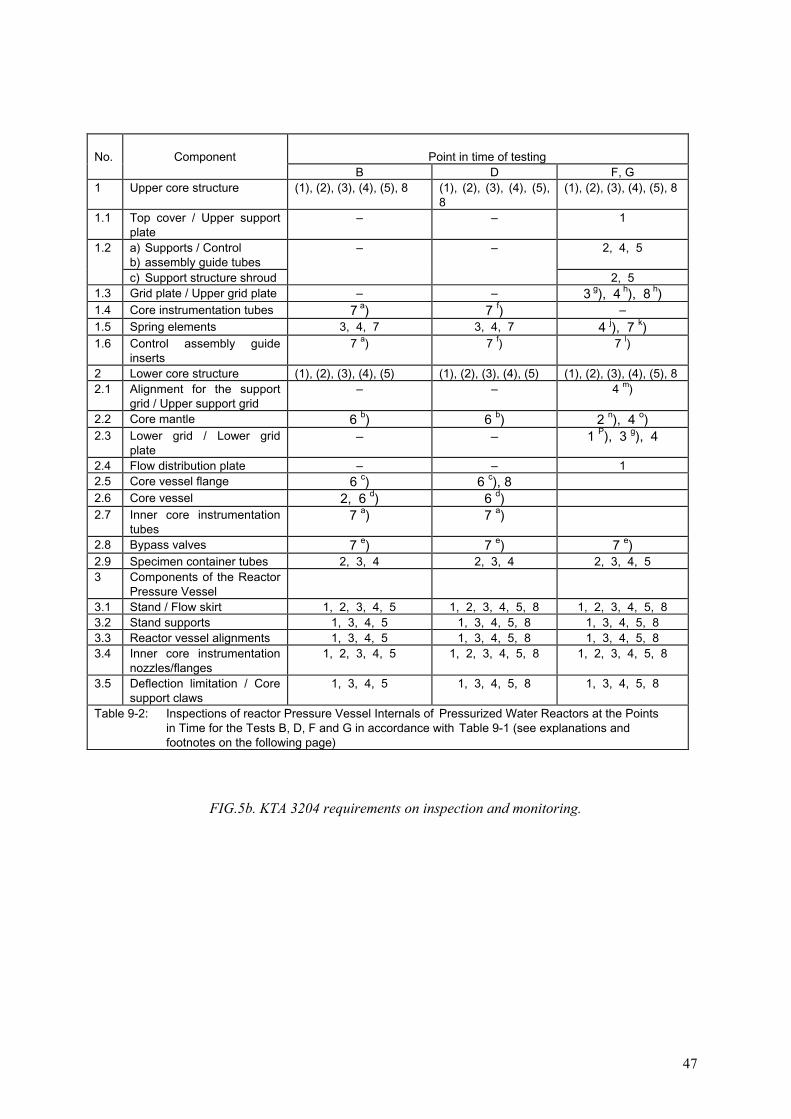
47
No. Component Point in time of testingB D F, G
1 Upper core structure (1), (2), (3), (4), (5), 8 (1), (2), (3), (4), (5),8
(1), (2), (3), (4), (5), 8
1.1 Top cover / Upper supportplate
– – 1
1.2 a) Supports / Controlb) assembly guide tubes
– – 2, 4, 5
c) Support structure shroud 2, 51.3 Grid plate / Upper grid plate – – 3 g), 4 h), 8 h)1.4 Core instrumentation tubes 7 a) 7 f) –1.5 Spring elements 3, 4, 7 3, 4, 7 4 j), 7 k)1.6 Control assembly guide
inserts7 a) 7 f) 7 l)
2 Lower core structure (1), (2), (3), (4), (5) (1), (2), (3), (4), (5) (1), (2), (3), (4), (5), 82.1 Alignment for the support
grid / Upper support grid– – 4 m)
2.2 Core mantle 6 b) 6 b) 2 n), 4 o)2.3 Lower grid / Lower grid
plate– – 1 P), 3 g), 4
2.4 Flow distribution plate – – 12.5 Core vessel flange 6 c) 6 c), 82.6 Core vessel 2, 6 d) 6 d)2.7 Inner core instrumentation
tubes7 a) 7 a)
2.8 Bypass valves 7 e) 7 e) 7 e)2.9 Specimen container tubes 2, 3, 4 2, 3, 4 2, 3, 4, 53 Components of the Reactor
Pressure Vessel3.1 Stand / Flow skirt 1, 2, 3, 4, 5 1, 2, 3, 4, 5, 8 1, 2, 3, 4, 5, 83.2 Stand supports 1, 3, 4, 5 1, 3, 4, 5, 8 1, 3, 4, 5, 83.3 Reactor vessel alignments 1, 3, 4, 5 1, 3, 4, 5, 8 1, 3, 4, 5, 83.4 Inner core instrumentation
nozzles/flanges1, 2, 3, 4, 5 1, 2, 3, 4, 5, 8 1, 2, 3, 4, 5, 8
3.5 Deflection limitation / Coresupport claws
1, 3, 4, 5 1, 3, 4, 5, 8 1, 3, 4, 5, 8
Table 9-2: Inspections of reactor Pressure Vessel Internals of Pressurized Water Reactors at the Pointsin Time for the Tests B, D, F and G in accordance with Table 9-1 (see explanations andfootnotes on the following page)
FIG.5b. KTA 3204 requirements on inspection and monitoring.

48
Explanations for Table 9-2:
Type of inspection to be performed:
1 = Search for foreign bodies connections 5 = Visual inspection of bolted2 = Visual inspection of the weld seam 6 = Dimensional check3 = Visual inspection regarding completeness 7 = Functional test4 = Visual inspection regarding mechanical damages 8 = Visual inspection of contacting surfaces
(1), (2) … (5): = The inspection shall be performed at the specified point in time as an integral surveyinspection of the component. Only random samples of individual subunits of the component need to beinspected.
1, 2, … 8: = A detailed inspection of the component shall be performed at the specified point in time.Footnotes to Table 9-2:
a) Inspection regarding free passage ways. Even in case of trial operation, this inspection is only required if it was not performed during fabrication on
the construction site.
b) Dimensional check of the relevant dimensions of the core mantle.
c) Check of the radial play between core vessel flange and reactor pressure vessel
d) Check of the outlet nozzle play between core vessel and reactor pressure vessel
e) Check of the free motion.
f) Inspection regarding free passage way. This inspection is only required if it was not already performed after trial operation without the core.
Note: An inspection after fabrication on the construction site cannot replace this inspection.
g) Fuel assembly alignment.
h) a)Guide piece of the grid plate alignment b)Fuel assembly alignment c) Pressure points of the fuel element hold-down device
j) a)Bolt protusion b)Fastening of the hold-down plates
k) Checking of the spring characteristics
l) Check of the freedom of movement, e.g. with the control rod, with a special test body
m) For abrasion tracks
n) Lock welds of the core mantle bolts
o) a)Core mantle sheets for possible contact points of the fuel assembly feet b)Core mantle sheets for possible contact points of the fuel assembly heads
p) Base support plate of the fuel elements
FIG.5c. KTA 3204 requirements on inspection and monitoring.
49
7. SERVICE EXPERIENCE AND RELATED MAINTENANCE
Up to now, the majority of events reported about problems in internals of PWR arerelated to stress corrosion or fatigue failures, including or not neutron irradiation effects.There are no events listed for WWER reactors since none have been reported to date. Inaddition to the detailed information given below, a summary of failures observed to date inrelation to dominant ageing mechanisms is given in Table XII.
7.1. FAILURE OF BOLTS AND SUPPORTING BEAMS OF THE THERMAL SHIELDS
In the earlier PWRs, failure of bolts occurred in the core barrel (e.g. in France, Italy,USA in 1968). The failure of the bolts, made of cold-worked 316 stainless steel, wasattributed to fatigue associated to flow induced vibrations of the thermal shield. The thermalshield was removed and the bolts replaced by new ones made of nickel alloy Inconel X-750.
Later on, in 1984 in France, at more than 100 000 hours of operation, several core barrelbolts fabricated of Inconel X-750 failed again. In that case, the intergranular cracking wasattributed to (IGSCC) in water. The bolts were replaced by new ones, using an improvedthermal treatment for the alloy. The neutron irradiation was not considered as playing asignificant role.
In the 1980s, similar problems were reported in USA or in Europe and were attributedagain to flow induced vibration.
TABLE XII. FAILURES OBSERVED IN RELATION TO AGEING MECHANISMS
SECTION Embrittlement Fatigue Corrosion Wear Irradiationcreep andswelling
Handlingincident
Upper internals
Control rods guide tubes X
Guide X
Guide tube support split pins X
Thermocouple columns X
Upper core plate fuel alignmentpins
X X
Lower internals
Baffles (bolts, plates) X X
Thermal Shield Fasteners orwelds
X
Locating Systems (RadialsKeys, etc.)
X
Lower instrumentation guidecolumns
X
Bottom instrumentation thimble X
50
7.2. CRACKING OF THE GUIDE TUBE SUPPORT SPLIT PINS
The guide tubes support pins are fixed to the control rod guides and are inserted in theupper core plate. They are made of alloy Inconel X-750. There is a is thread at one end of thepin and the other end has a long slit parallel to the axis which is inserted in the upper coreplate. The first failure of these pins were recorded in Japan in 1978, then in France in 1982, inthe USA in 1983 and in the Republic of Korea in 1997.
The failure was attributed to IGSCC in water, which is known to occur in high nickelmaterials. The neutron irradiation at this location is very low and was not considered as beinga significant factor in this case. Soon after the failure occurred, tools to control thedegradation and replace the pins became available.
Improved replacement pins were developed with a modified material (solutionannealing at a higher temperature ~1100°C), a new fabrication route, a new design reducingthe in service stresses and new installation specifications. Shot peening was also used at thefinal stage of the fabrication of the pins. In the Republic of Korea, the support pins werereplaced with strain hardened Type 316 stainless steel ones.
The life of the pins has been significantly increased by these mitigation methods but theproblem is not yet considered as completely solved.
7.3. CRACKING OF FUEL ASSEMBLY ALIGNMENT PINS MADE FROMINCONEL X-750
A design feature common to all Siemens/KWU PWRs is that each fuel assembly isfixed in position relative to the core internals by means of two lower (in the lower coresupport) and two upper alignment pins (in the grid plate). Since 1980, there have been isolatedreports of broken upper alignment pins in some plants and this damage was attributed toIGSCC of the material Inconel X-750, which had been chosen for its wear resistant properties.Although the number and location of the broken pins did not necessitate immediate repairs, anumber of defective pins were replaced with pins made from austenitic stainless steel type316 Ti (German designation 1.4571), protected against excessive mechanical wear by achromium carbide hard-facing coating. No further cracking due to IGSCC has been found inthe replaced pins so far. All the upper alignment pins in the Konvoi plants are equipped withpins made of the new material with some modifications in the design of the pins.
7.4. BAFFLE JETTING
At the beginning of the 1980s, jets of water through the baffles created damage to thefuel elements. This effect was related to the pressure between the baffles and the core vesselwith the “down flow” of the water in this location. Some modifications in the formers,assuring the “up flow” of the water, have reduced the pressure and suppressed the bafflejetting. This "up flow" measure, was implemented practically everywhere later on.
7.5. CRACKING OF THE BAFFLE BOLTS
In the 1980s inspections indicated baffle bolts cracking. The bolts are made of 316 coldworked stainless steels. They failed by intergranular cracking. Normally, 316 steel is not proneto IGSCC in this water environment and all the bolts cracked were initially located in thesecond and third rows from the bottom, that is exactly the place corresponding to the highest

51
neutron irradiation. This demonstrates that the neutron irradiation is a significant feature forthis cracking, even if the exact mechanism is unknown now. It is difficult to conclude whetherthe bolts cracked by IASCC or due to irradiation embrittlement, or by other IGSCCphenomena. To date, baffle bolt cracking was observed only in plants with the “down-flow”design.
This cracking is a concern and made necessary the development of ultrasonic methodsfor the non-destructive examination of the bolts. In France, in 1994, the maximum number ofbolts with a suspicion of cracking was 57 on one plant (Bugey 2). The indications aresignificantly different from plant to plant. Measures are taken to be able to make an efficientnon destructive examination of the bolts and to replace them if necessary.
In Belgium, the situation is similar at Tihange 1. Twenty-one bolts were detected ascracked in 1991 and 90 bolts replaced in 1995 (as reported at the 1995 meeting of theInternational Working Group on Life Management of Nuclear Power Plants).
The possibility of changing all the lower internals is also studied in Europe and in Japan[19, 20].
In Germany, damage to the baffle former structure was first discovered in 1978 at aPWR plant. During the inspection, an enlarged gap of approximately 2 mm was foundbetween two baffles. An ultrasonic examination revealed that a number of the Inconel X-750baffle former bolts were defective (some bolts gave no back echo, others gave back echoeswhich did not correspond to the bolt length. When the bolts were removed, some of themwere found to be broken, others had cracks of different sizes. Studies of the cracks showedthat the cause of damage was not fatigue, but rather IGSCC. The crack locations in thedamaged baffle-former bolts were in the transition between the bolt head and the necked-down shaft (extending into the hexagonal socket), within the necked-down shaft and in thetransition between the shaft and the thread and in the thread itself, as illustrated in Fig. 6. Allof the baffle former bolts were examined by ultrasonic testing. Damage to Inconel X-750baffle former bolts was subsequently found in other German plants as well. No defects werefound in bolts made from austenitic stainless steel. Today it is well known that the nickelbased alloy Inconel X-750 is susceptible to IGSCC in highly pure high temperature reactorcoolant.
FIG. 6. Siemens/KWU baffle-former bolts.

52
Following this event, in Siemens/KWU plants, the baffle former bolts made of InconelX-750 have been replaced (a total of over 5100) with bolts made of material 1.4571 (Type 316Ti, cold worked material). In new plants, erected after the detection of this kind of cracking,bolts made from the alternative material were already installed during the original assembly.Following this material change no more defects due to this degradation mechanism have beenfound.
7.6. WEAR OF BOTTOM INSTRUMENTATION THIMBLES.
Bottom instrumentation thimbles are present in reactors in the USA and France. Theyare relatively long tubes having a small wall thickness (1.15 to 1.31 mm). The water flowaround them can generate vibrations and wear by local contact with their guides, leading thento leakage. To date, thimble tube wear has been observed in at least 20 plants. Replacement bya thicker thimble is sometimes performed when this occurs.
7.7. WEAR OF CONTROL ROD GUIDES
In RVI components, wear between control rods and guide tubes results from the axialsliding which occurs during insertions and withdrawals, and from the transverse motionscaused by flow induced vibration. This can be improved either by the use of wear resistantdeposit or by design modification, or both.
7.8. HANDLING INCIDENTS
Internal structures are complex and have to be removed periodically for refuelling or forin service inspection. Handling of these complex structures need a special care in order toavoid hitting the surrounding parts. When this occurs, damage can be created either bydistortion of some parts which can lead to improper operation or by local straining or coldwork, which can help to promote SCC or other phenomena.
As an example, during careless handling, the pins aligning the fuel assembly and theupper core plate can be distorted. When this occurs, a fuel assembly can be lifted up when theupper core structures are removed and fall down afterwards. This problem was observedseveral times in the USA and in Europe. Careful handling is the solution to this problem.

53
8. RVI AGEING MANAGEMENT PROGRAMME
The information presented in this report indicates that the operating environmentincluding primary coolant water and radiation can cause ageing degradation of RVI. In8particular, ageing mechanisms of radiation embrittlement, stress corrosion cracking, and thecombination of radiation and stress corrosion cracking, known as irradiation assisted stresscorrosion cracking can lead to both safety and economic concerns. While the ageingmechanisms of thermal ageing, corrosion, wear and fatigue are not considered to be safetysignificant by themselves, they can increase the safety significance of irradiationembrittlement and SCC. However, these ageing mechanisms could be of economic concern ontheir own.
The previous sections of this report dealt with important elements of a PWR RVI ageingmanagement which should aim to maintain the fitness for service of RVI at nuclear powerplants. This section describes how these elements are integrated within a plant specific RVIageing management programme (utilizing a systematic ageing management process, which isan adaptation of Deming’s “plan-do-check-act” cycle for ageing management, Fig. 7). Such anageing management programme should be in accordance with guidance prepared by aninterdisciplinary RVI ageing management team organized at the corporate level or ownerlevel. For guidance on the organizational aspects of a plant ageing management programmeand interdisciplinary ageing management team, refer to IAEA Safety Report Series No. 15,“Implementation and Review of Nuclear Power Plant Ageing Management Programme“ [21].
A comprehensive understanding of RVI, their ageing degradation and the effect of thedegradation on the ability of the RVI to perform their design functions is a fundamental basisfor an ageing management programme. This understanding is derived from the knowledge ofthe design basis (including the applicable codes and regulatory requirements), the operatingand maintenance history (including surveillance results), the pre-service and in-serviceinspection results, and generic operating experience and research results.
In order to maintain the integrity or fitness for service of RVI, it is necessary to controlwithin defined limits the aged related degradation of the RVI. Effective degradation control isachieved through a systematic ageing management process consisting of the following ageingmanagement tasks, based on understanding of RVI ageing:
�� operation within specified operating conditions aimed at minimizing the rate ofdegradation (managing ageing mechanisms);
�� inspection and monitoring consistent with requirements aimed at timely detection andcharacterization of any degradation and validating the ageing prediction;
�� assessment of the expected or observed degradation in accordance with appropriateguidelines to determine integrity and fitness for service;
�� maintenance, i.e. repair or replacement to correct or eliminate unacceptable degradation(managing ageing effects).
An RVI ageing management programme co-ordinates programmes and activitiescontributing to the above ageing management tasks in order to detect and mitigate ageingdegradation before RVI safety margins are compromised. This programme reflects the level ofunderstanding of the RVI ageing, the available technology, the regulatory licensingrequirements, and the plant life management consideration/objectives. Timely feedback ofexperience is essential in order to provide ongoing improvements in the understanding of the
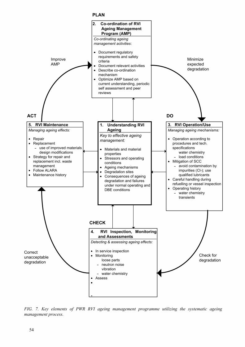
54
1. Understanding RVIAgeing
Key to effective ageingmanagement:
�� Materials and materialproperties
�� Stressors and operatingconditions
�� Ageing mechanisms�� Degradation sites�� Consequences of ageing
degradation and failuresunder normal operating andDBE conditions
2. Co-ordination of RVIAgeing ManagementProgram (AMP)
Co-ordinating ageingmanagement activities:
�� Document regulatoryrequirements and safetycriteria
�� Document relevant activities�� Describe co-ordination
mechanism�� Optimize AMP based on
current understanding, periodicself assessment and peerreviews
4. RVI Inspection, Monitoringand Assessments
Detecting & assessing ageing effects:
�� In service inspection�� Monitoring
�� loose parts�� neutron noise�� vibration�� water chemistry
�� Assess��
�
3. RVI Operation/UseManaging ageing mechanisms:
�� Operation according toprocedures and tech.specifications�� water chemistry�� load conditions
�� Mitigation of SCC�� avoid contamination by
impurities (Cl-); usequalified lubricants
�� Careful handling duringrefuelling or vessel inspection
�� Operating history�� water chemistry�� transients
5. RVI MaintenanceManaging ageing effects:
�� Repair�� Replacement
�� use of improved materials�� design modifications
�� Strategy for repair andreplacement incl. wastemanagement
�� Follow ALARA�� Maintenance history
Minimizeexpecteddegradation
ImproveAMP
ACT DO
Correctunacceptabledegradation
Check fordegradation
FIG. 7. Key elements of PWR RVI ageing management programme utilizing the systematic ageingmanagement process.
CHECK
PLAN
55
RVI ageing degradation and in the effectiveness of the ageing management programme. Themain features of an RVI ageing management programme, including the role and interfaces ofrelevant programmes and activities in the ageing management process, are shown in Fig. 7and discussed in Section 8.1 below. Application guidance is provided in Section 8.2. Nationaland international R&D programmes in support of RVI ageing management are outlined inSection 8.3.
8.1. KEY ELEMENTS OF THE AGEING MANAGEMENT PROGRAMME
8.1.1. Understanding ageing
Understanding RVI ageing is the key to effective management of RVI ageing. It is thekey to: integrating ageing management activities within a systematic ageing managementprogramme, managing ageing mechanisms through prudent operating procedures andpractices (in accordance with technical specifications); detecting and assessing ageing effectsthrough effective inspection, monitoring, and assessment methods and managing effects usingproven maintenance methods. This understanding consists of: a knowledge of RVI materialsand material properties, stresses and operating conditions; likely degradation sites and ageingmechanisms; condition indicators and data needed for assessment and management of RVIageing and effects of ageing on safety margins.
The understanding of RVI ageing is derived from the RVI baseline data, the operatingand maintenance histories, and external experiences. This understanding should be updatedcontinuously to provide a sound basis for the improvement of the ageing managementprogramme consistent with operating, inspection, monitoring, assessment and maintenancemethods and practices.
The RVI baseline data consists of the performance requirements, the design basis(including codes, standards, regulatory requirements), the original design, the manufacturersdata (including material data), and the commissioning data (including pre-service inspectiondata). The RVI operating history includes the pressure/temperature records, number oftransients, system chemistry records, fluence/dpa log, and all ISI results. The RVImaintenance history includes design modifications, replacement parts/components, inspectionrecords and assessment and timing of maintenance performed. Retrievable, up to date recordsof this information are needed for comparison against applicable codes, standards, regulatoryrules, and other external experience.
External experience consists of the operating and maintenance experience of (a) RVI ofsimilar design, materials of construction, and fabrication; (b) RVI with similar operatinghistories, even if the RVI designs are different and (c) relevant research results. It should benoted that effective comparisons or correlation with external experience requires a detailedknowledge of the RVI design and operation. The present report is a source of suchinformation. However, this information has to be kept up to date using feedback mechanismsprovided, for example, by owner groups. External experience can also be used whenconsidering the most appropriate inspection method, maintenance procedure, and technology.
8.1.2. Co-ordination of the ageing management programme
Existing programmes relating to the management of RVI ageing include operations,surveillance and maintenance programmes, operating experience feedback, research anddevelopment and technical support programmes. Experience shows that ageing management

56
effectiveness can be improved by co-ordinating relevant programmes and activities within anageing management programme utilizing the systematic ageing management process. Safetyauthorities increasingly require licensees to define and implement such ageing managementprogrammes for selected systems, structures, and components important to safety. The co-ordination of an RVI ageing management programme includes the documentation ofapplicable regulatory requirements and safety criteria, of relevant programmes and activitiesand their respective roles in the ageing management process, and of mechanisms used forprogramme co-ordination and continuous improvement. Continuous ageing managementprogramme improvement or optimization is based on current understanding of RVI ageingand on results of periodic self-assessment and peer reviews.
8.1.3. Operation/use of reactor vessel internals
NPP operation has a significant influence on the rate of degradation of plant systems,structures and components. Exposure of RVI to operating conditions (e.g. temperature,pressure, and water chemistry) outside prescribed operational limits could lead to acceleratedageing and premature degradation. Neutron and gamma radiation also has an effect on the rateof RVI degradation. Since operating practices influence RVI operating conditions, NPPoperations staff have an important role to play in minimizing age related degradation of RVIby maintaining operating conditions within prescribed operational limits to avoid acceleratedageing. Examples of such operating practices are:
�� performing maintenance according to procedures designed to avoid contamination ofRVI components with boric acid or other chemicals containing halogens;
�� on-line monitoring and record keeping of operational data necessary for predictingageing degradation and defining appropriate ageing management actions;
�� fuel loading scheme to manage the rate of radiation embrittlement, IASCC, andswelling.
Effective ageing management of the RVI and a possible plant life extension requiresprudent operation and maintenance of plant systems that influence RVI operational conditions(not only the primary system but also the auxiliary systems like water purification andinjection systems) and record keeping of operational data.
8.1.4. Inspection, monitoring and assessment
Inspection and monitoring
RVI inspection and monitoring activities are designed to detect and characterizesignificant component degradation before RVI safety margins are compromised. Results ofRVI inspections together with the understanding of the RVI ageing degradation, provide thebasis for managing detected ageing effects through maintenance and/or changes in operatingconditions.
Inspection and monitoring of RVI degradation falls in two categories:
�� in-service inspection;�� monitoring of temperature and pressures, water chemistry, transients (relative to
fatigue).
The ISI programme should adequately address the most critical sections identifiedthrough the evaluation of ageing mechanisms.

57
Monitoring temperature provides input for the assessment of radiation embrittlement,swelling, and IASCC. Transient monitoring provides realistic values of thermal stressesfluctuations as opposed to design basis thermal stress fluctuations for fatigue assessments.
Assessment
The main safety function of the RVI is to protect the core (fuel), maintain stability toreceive the control rods when inserted and to provide a passage for coolant flow. Safetymargins are part of the design and licensing requirements of an NPP to ensure the integrity ofthe RVI under both normal and accident conditions. An integrity assessment is used to assessthe capability of all the components (baffle plates, former and baffle bolts, core barrel, etc.) toperform the required safety function within the specified margin of safety, during the entireoperating interval until the next scheduled inspection. The safety assessment must alsoinclude the potential of a double-ended-pipe break and the resulting blowdown forces on theRVI.
8.1.5. Maintenance, repair and replacement
Maintenance actions that have been used to manage ageing effects detected byinspection and monitoring methods in different components of the RVI are described inSection 7. Decisions on the type and timing of the maintenance actions are based on anassessment of the observed ageing effects, available decision criteria, understanding of theapplicable ageing mechanism(s) and the effectiveness of available maintenance technologies.
Maintenance actions for management of radiation embrittlement are rather limited.Unlike the reactor pressure vessel fuel management programmes (low leakage core) andreactor vessel annealing, irradiation embrittlement of the reactor vessel internals can only beminimized by reducing the reactor power. Maintenance actions for managing IASCC, IAC, orIGSCC can be either a modification of the coolant chemistry or replacement of RVIcomponents with materials that are less susceptible to intergranular stress corrosion crackingor improved design. RVI components that have been determined by inspection to exhibitcracking, such as baffle plates, baffle bolts, guide tube support pins, etc. can be replaced. Theaddition of zinc to the primary coolant has the potential to minimize or prevent future stresscorrosion cracking.
Currently, a number of methods to mitigate SCC in PWR RVI are being studied. Themethods currently under evaluation are the addition of zinc to the primary reactor coolant andthe coating of RVI components with one of the noble metals. The addition of zinc to theprimary coolant loop was intended to reduce the activity of the RVI as part of the ALARAprogram. However, EPRI studies have indicated that zinc additions to the primary reactorcoolant could also retard SCC in nickel based alloys such as Alloy 600. There are alsoindications that zinc additions to the primary reactor coolant could prevent or retard SCC inaustenitic stainless steel alloys.
It has recently been reported that introducing noble metals as an alloy addition foraustenitic stainless steel or as a coating to already fabricated RVI components could retard orprevent SCC.
Coating of the RVI components subject to wear with nickel or chromium can minimizethe amount of wear. Due to the ingress of Co into the medium, Co-bearing materials such asStellite should be avoided as hard-facing materials.
58
8.2. APPLICATION GUIDANCE
The RVI ageing management programme should address both the safety and economicaspects of RVI ageing to ensure both the integrity and serviceability of RVI during the designlife and any extended service life of the RVI. The following sections provide guidance ondealing with the relevant ageing mechanisms.
8.2.1. Embrittlement
As already stated, there are two types of embrittlement which could affect RVIcomponents. These are irradiation embrittlement, which may affect core region internals, andthermal ageing embrittlement, which may affect the cast stainless steel parts and partsmanufactured from martensitic stainless steel.
Irradiation embrittlement
Irradiation embrittlement of RVI falls under the category of long term safety relatedageing management. All RVI materials are to some degree sensitive to radiationembrittlement. The ageing management programme activities which address radiationembrittlement can provide material data for fracture mechanics analysis. This can be achievedby:
�� fluence mapping;�� utilization of radiation embrittlement databases/trend curves to predict the degree of
radiation embrittlement for a given RVI component;�� laboratory testing of RVI that were either replaced during service or that failed during
service.�
Thermal ageing embrittlement
Thermal ageing embrittlement can be addressed by:
�� utilization of databases pertaining to the degradation of cast and martensitic stainlesssteel due to ageing to predict the degree of the embrittlement for a given RVIcomponent;
�� periodic ISI of all cast stainless steel RVI components to ensure timely detection offlaws; if any indications/flaws are found during the ISI, the component should bereplaced.
8.2.2. Fatigue
A fatigue assessment is conducted in the design phase in order to prevent any crackinitiation. This assessment is made by using the cyclic stresses and number of cycles given inthe RVI design report. These values are determined using the estimates of the type andnumber of transients provided by the NSSS vendors.
In the ageing management programme the following points should be considered:
�� Transient monitoring can be used to obtain more accurate estimates of both the totalnumber of cycles and the stress ranges. For RVI put into operation prior to theinstallation of a transient monitoring system, a review of past operating records must be
59
made to determine the number and type of transients prior to the installation of themonitors. Transient monitoring system is a very valuable tool for predicting the servicelife of RVI and should be part of the ageing management programme.
�
�� If a flaw is detected during ISI, fracture mechanics analysis, including fatigue crackgrowth prediction must be performed using a correlation between cyclic crack growthrate, da/dN, and stress intensity range �K. The growth of the flaw can be determinedusing the methodology given for instance in Appendix A to ASME Section XI or anyequivalent national code.
�
�� The databases available that incorporate the effect of radiation on crack growth rateda/dN versus �K and on fracture toughness K should be utilized to determine if thecracked component should be replaced.
�
�� If a flaw is detected during ISI, consideration should be given to removing the flaw bytaking a boat sample or removable of the component containing the flaw. Amicrostructural analysis should be performed to determine if striations are evident on thesurface of the flaw. Striations on the surface of a flaw are an indication that the initiationof the flaw or the growth of the flaw is due to fatigue.
�
8.2.3. Stress corrosion cracking
The following activities of the ageing management programme address stress corrosioncracking:
�� fluence mapping;�� utilization of databases that contain data on the effect of irradiation on the susceptibility
of reactor internal materials to stress corrosion cracking (including modes of cracking,IGSCC or TGSCC, materials chemistry, and most importantly the fluence/dpa level);
�� periodic in-service inspection performed on the basis of the data given in suchdatabases;
�� fatigue initiation and crack growth analysis utilizing fracture mechanics methodologyperformed if indications/flaws are reported by the in-service inspection;
�� deterministic or probabilistic structural analysis performed to determine the maximumnumber of cracked bolts which can be tolerated.
8.3. NATIONAL AND INTERNATIONAL R&D PROGRAMMES
Input from national and international research and development programmes should beclosely followed and the results, where applicable, should be incorporated into the ageingmanagement programme.
In Japan, the Nuclear Plant Rejuvenation Reliability Test Programme is beingperformed by the Nuclear Power Engineering Corporation (NUPEC) to demonstrate thereliability of RVI replacement technology by performing mock up tests in full scale testfacilities. This programme includes the replacement of the following PWR RVI components:
�� core barrel;�� bottom mounted instrumentation adapter.
Repair welding technology of irradiated materials (WIM Project) has been conducted bythe Japan Power Engineering and Inspection Corporation (JAPEIC) since October 1997. In
60
the project, the repair welding technology will be developed for neutron irradiated coreinternals, such as baffle plate, core barrel and radial support and the reactor vessel. JAPEIChas also dedicated the verification tests of the surface treatment technology for the preventionof PWSCC in Nuclear Power Plant Maintenance Technology (PMT Project). The technologyis expected to be applied to PWR RVI components, for example, the bottom penetrations ofthe in-core instrumentation.
A joint Japan and Russia research and development programme is under way to studystructural materials of WWER RVI. This programme was approved by MINATOM of Russiain April, 1997 and addresses the following:
�� investigation of RVI material (18/10 austenitic stainless steel) degradation underoperating conditions;
�� visual and status measurements of the reactor internals at one of the operating WWER-1000 plants;
�� development of the following procedures:�� 2D and 3D stress–strain analysis (allowing for non-uniform power distribution,
cooling conditions, and degradation of material properties due to irradation);�� fatigue strength and brittle fracture strength;�� revision of the neutron flux analysis procedures;
�� revision of the “Provisional Regulations for Strenght Analysis of WWER Internals”.
In France, EDF, CEA, and Framatome are conducting a programme to study thebehaviour of internals materials after a high irradiation (up to 80 dpa at 328�C). Standardmaterials, 304 and 316 cold worked stainless steel are being studied as well as proposedimproved materials. The irradiation is being carried out in the Russian fast breeder reactorBOR 60. The Westinghouse Owners Group (WOG) and Westinghouse are also participatingin the EDF, CEA, Framatome programme to evaluate current materials.
Another programme identified as the Co-operative Industry Research (CIR) programme,managed by EPRI and aimed at developing a mechanistic understanding of IASCC, isgenerating a methodology to predict components’ behaviour and identify possiblecountermeasures to IASCC. The CIR programme research effort seeks to answer questions inthe areas of material susceptibility, water chemistry, and stress, using existing irradiatedmaterial from other programmes and to carry out controlled experiments in hot cells and testreactors.
In addition to the above research and development programmes addressing IASCC inPWR reactor internals materials, there are a number of programmes addressing IASCC inBWR reactor internals materials. These programmes include the BWR Vessel InternalsProgramme, which is sponsored by the BWR Owners Group and EPRI; the IASCC HaldenReactor Project and the EPRI CIR Programme.
The results, data and lessons learned from the above research and developmentprogrammes should be incorporated into the existing databases and utilised in RVI ageingmanagement programmes.

61
REFERENCES
[1] INTERNATIONAL ATOMIC ENERGY AGENCY, Code on the Safety of NuclearPower Plants: Operation, Safety Series No. 50-C-O (Rev. 1), IAEA, Vienna (1988).
[2] INTERNATIONAL ATOMIC ENERGY AGENCY, In-Service Inspection for NuclearPower Plants: A Safety Guide, Safety Series No. 50-SG-O2, IAEA, Vienna (1980).
[3] INTERNATIONAL ATOMIC ENERGY AGENCY, Maintenance of Nuclear PowerPlants: A Safety Guide, Safety Series No. 50-SG-O7 (Rev. 1), IAEA, Vienna (1990).
[4] INTERNATIONAL ATOMIC ENERGY AGENCY, Surveillance of Items Important toSafety in Nuclear Power Plants: A Safety Guide, Safety Series No. 50-SG-O8 (Rev. 1),IAEA, Vienna (1990).
[5] INTERNATIONAL ATOMIC ENERGY AGENCY, Methodology for Management ofAgeing of Nuclear Power Plant Components Important to Safety, Technical ReportsSeries No. 338, IAEA, Vienna (1992).
[6] INTERNATIONAL ATOMIC ENERGY AGENCY, Data Collection and RecordKeeping for the Management of Nuclear Power Plant Ageing, A Safety Practice, SafetySeries No. 50-P-3, IAEA, Vienna (1991).
[7] CEA, TECNATOM and VTT, Effect of Irradiation on Water Reactors Internals , AMESreport No. 11, EUR 17694 EN, European Commission, Brussels–Luxemburg (1997).
[8] Regulations for Strength Analysis of Equipment and Piping of Nuclear Power Plants,PNAE G-7-002-87, Energoatomizdat, Moscow (1989).
[9] AMERICAN SOCIETY OF MECHANICAL ENGINEERS, ASME Boiler and PressureVessel Code, ASME, New York (1998).
[10] ASSOCIATION FRANÇAISE POUR LES RÈGLES DE CONCEPTION ET DECONSTRUCTION DES MATÉRIELS DES CHAUDIÈRES ELECTRO-NUCLÉAIRES, Paris, RCC-M, Règles de Conception et de Construction des Matérielsdes Ilôts Nucléaires PWR, AFCEN (1988).
[11] NUCLEAR SAFETY STANDARDS COMMISSION, Safety Standards, KTA 3204Reactor Pressure Vessel Internals, KTA, Cologne (6/1998).
[12] OFFICE OF THE FEDERAL REGISTER, Code of Federal Regulations (Energy)10 Part50, Domestic Licensing of Production and Utilization Facilities: 50:50 Issuance ofLicenses and Construction Permits, Washington (1999).
[13] General Proposals for Providing the Safe Operation of Nuclear Power Plants. OPB-88/97, NP-001-97 PNAE G-01-011-89, Gosatomnadzor of Russia, Moscow (1997).
[14] Regulations for Safe Operation of Reactor Installations of Nuclear Power Plants, PBYaRU AS-89, PNAE G-1-024-90, Gosatomnadzor of Russia, Moscow (1990).
[15] Equipment and Piping of Nuclear Power Plants, Welding and Cladding, GeneralPropositions, PNAE G-7-009-89, Energoatomizdat, Moscow (1991).
[16] Equipment and Piping of Nuclear Power Plants. Welds and Claddings. Regulations forinspection, PNAE G-7-010-89, Energoatomizdat, Moscow (1991).
[17] Regulations for Design of Seismically Safe Nuclear Power Plants, PNAE G-5-006-87,Energoatomizdat, Moscow (1989).
[18] CHUNG, M., Thermal Ageing of Decommissioned Reactor Cast Stainless SteelComponents and Methodology for Life Prediction, ASME PVP, Vol. 171, ASME, NewYork (1989) 111.
[19] DUPRAZ, B., LECOQ, P., GODIN, R., Lifetime Management of the French NuclearPower Plants, Conference Papers of PLIM + PLEX '95, Nuclear Eng. Int’l and SFANS,Nice (1995).
[20] NUCLEAR POWER ENGINEERING CORPORATION, NUPEC Annual Report 1997,Nuclear plant Rejuvenation Technology Reliability Test, Tokyo (1997).

62
[21] INTERNATIONAL ATOMIC ENERGY AGENCY, Implementation and Review ofNuclear Power Plant Ageing Management Programme, Safety Report Series No. 15,IAEA, Vienna (1999).
63
ABBREVIATIONS
AISI American Iron and Steel InstituteALARA as low as reasonably achievableASME American Society of Mechanical EngineersASTM American Society for Testing and MaterialsBMI bottom mounted instrumentationCS core support structuresdpa displacement per atomE/C erosion corrosionECCS emergency core cooling systemECP electrochemical potentialEDF Electricité de FranceEPRI Electric Power Research InstituteFA fuel assemblyFAC flow accelerated corrosion fuel assemblyGOST Russian national standardIASCC irradiation assisted stress corrosion crackingID internal diameterIGSCC intergranular stress corrosion crackingIS internals structuresISI in-service inspectionKTA Kerntechnischer Ausschuss, German nuclear safety codeLBB leak before breakLCP lower core plateLOCA loss of coolant accidentMINATOM Ministry of Atomic Energy of the Russian FederationNSSS nuclear steam supply systemOD outer diameterPWSCC primary water stress corrosion crackingR&D research and developmentRCC-M Règles de Conception et de Construction des Matériels des Ilôts
Nucléaires, French codeRCCA rod cluster control assemblyRPV reactor pressure vesselRVI reactor vessel internalsSAR safety analysis reportSCC stress corrosion crackingSSC systems, structures and componentsTGSCC transgranular stress corrosion crackingTIG tungsten inert gas welding processUCP upper core plateUSNRC United States Nuclear Regulatory Commission

.

65
CONTRIBUTORS TO DRAFTING AND REVIEW
Brumovsky, M. NRI, Czech RepublicDragunov, Yu.G. OKB Gidropress, Russian FederationErve, M. Siemens/KWU, GermanyHavel, R. Czech RepublicMager, T.R. Westinghouse Electric Corporation, USAMattis, R. Siemens/KWU, GermanyNonaka, A. NUPEC, JapanPachner, J. International Atomic Energy AgencyPetrequin, P. CEA, France
Consultants MeetingsVienna, Austria, 18–22 May 1998
Erlangen, Germany, 2–4 December 1998

99-0
3597