putting enzymes to work™ - national energy … library/research/coal/carbon capture...1 putting...
TRANSCRIPT

1
Putting enzymes to work™
Alex Zaks, Ph.D.Akermin, Inc.
October 7th, 2014
INTERNATIONAL CONFERENCE ON GREENHOUSE GAS TECHNOLOGIES
Low energy CO2 capture enabled by biocatalyst delivery system

2
DOMINANT APPROACH FOR CO2 CAPTURE TODAY: CHEMICAL ABSORPTION WITH AMINES
High operating costs & poor environmental profile Increases energy requirements Relies on volatile solvents Generates hazardous by‐products Accompanied by solvent degradation
Inadequate for large‐scale CO2 capture from flue gas streams
2
Where does it fall short?

3
ALTERNATIVE SOLVENTS
The use of K2CO3 requires a catalyst
3
Solvent Characteristics Baseline(Amines) K2CO3
No amine aerosol emissions X
Non‐volatile (No VOC or HAPs) X
Non toxic X
High Capture Rate X
Oxidative stability X
Low viscosity X
Low corrosion X
Limited flue gas polishing needed X
K2CO3 is kinetically slow but otherwise highly attractive solvent

4
Interconverts CO2 and HCO3‐ to maintain acid‐base
balance and transport CO2 out of tissues.
A family of ubiquitous enzymes Mammals, aquatic organisms, insects, plants,
fungi, bacteria and archaea
Active site contains metal (Zn2+)
MW ~ 30,000Desirable characteristics: Thermostable Resistant to high pH (9.5‐10.5) Expressed at high levels with few impurities
CARBONIC ANHYDRASE: NATURE’S PERFECT CATALYST
4

5
CHALLENGE
How to make a biocatalyst evolved in nature work under industrial conditions with following stressors:
5
Enzyme optimization and advanced delivery is critical
Temperature (40‐ 105 oC) Extreme pH (9.8‐10.2) Impurities (SOx, NOx, etc.) Shear Forces Multiphasic systems

6
AKERMIN’S BIOCATALYST DELIVERY SYSTEM
6
Successful biocatalyst approach enables: • Non‐toxic, non‐volatile solvent(s)• Novel process schemes
Enzyme
Protected from inactivation in proprietary polymer film
High surface area polymer films enable
higher mass transfer rate
Coated packing
Micro‐particles
Options for biocatalyst delivery

7 7
Installed at NCCC December 2012FIELD PILOT UNIT DEMONSTRATION
8.33” ID x 26 ft packingGas: 30 Nm3/hrLiquid: 275 LPH
Unit with immobilized enzyme operated May –Oct 2013
Sulzer M500X

8
FIELD TRIAL: LONG‐TERM PERFORMANCE
8
6 months
Minimum Achievable Now Projected
1 yearCommercial
Readiness Goal
2 yearsLIFETIME
9 months 18 months
Half‐life 539 days
2,800 hours on CO2 steam with 99% availability
9
0
10
20
30
40
50
60
70
80
90
100
0 1 2 3 4 5 6 7 8
CO2Ca
pture (%
)
Test Time (hours)
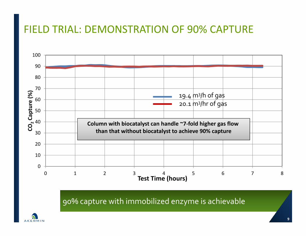
19.4 m3/h of gas20.1 m3/hr of gas
Column with biocatalyst can handle ~7‐fold higher gas flow than that without biocatalyst to achieve 90% capture
9
FIELD TRIAL: DEMONSTRATION OF 90% CAPTURE
90% capture with immobilized enzyme is achievable

10 10
~3.4 GJ/tCO2 with K2CO3, basic flow sheet
3.03.23.43.63.84.04.24.44.64.85.0
60 65 70 75 80 85 90 95 100 105
Rebo
ilerH
eat D
uty (GJ/t C
O2)
Reboiler Temperature (°C)
0.25 (Lean)
0.30
0.35
0.30 (no kinetic limitation)
IMPACT OF KINETIC LIMITATIONS ON REBOILER DUTY OPERATED WITH KHCO3

11
High CO2 loading Low regeneration energy Non‐volatile Low EH&S risks Low molecular weight Thermally stable Highly water‐soluble Manufacturing route established Used in the past for gas treating
CHALLENGE: HOW TO FURTHER MINIMIZE ENERGYSecond generation solvent, AKM24

12
LONG‐TERM PERFORMANCE OF THE PILOT WITH K2CO3 AND AKM24
12
Long‐term stability with both solvents demonstrated
0
10
20
30
40
50
60
70
80
90
100
100 600 1100 1600 2100 2600 3100 3600
CO2Ca
pture (%
)
Time On Stream (hours)
12% CO2 – K2CO3 4% CO2 – K2CO3
4% CO2 – AKM‐24
12% CO2 – AKM‐24

13
SPECIFIC REBOILER DUTY FOR K2CO3 AND AKM‐24
13
AKM‐24 is estimated to achieve 30% reduction in reboiler heat duty
2.0
2.5
3.0
3.5
4.0
4.5
5.0
60 70 80 90 100 110 120
Specific Re
boiler D
uty (GJ/t C
O2)
Reboiler Temperature (°C)
AKM‐24: Blank
AKM‐24: 15X
K2CO3, Blank
K2CO3, 15X
14
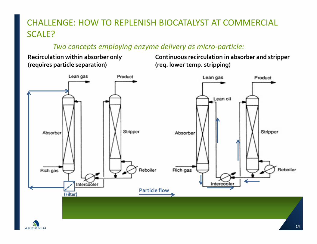
CHALLENGE: HOW TO REPLENISH BIOCATALYST AT COMMERCIAL SCALE?
Recirculation within absorber only (requires particle separation)
Continuous recirculation in absorber and stripper (req. lower temp. stripping)
Particle flow(Filter)
Two concepts employing enzyme delivery as micro‐particle:
14

15
NEW PROJECT SUPPORTED BY U.S. DEPARTMENT OF ENERGY
15
$3 million award; work initiated in Oct’13
Goals Demonstrate delivery of
enzyme on micro‐particle Complete characterization of
AKM24 Test advanced system design Further reduction of energy
and capital costs
• FOCUS ON MICRO‐PARTICLE• RECIRCULATIONTHROUGH ENTIRE
SYSTEM
• AKM24

16
ENHANCEMENT FACTOR FOR GEN‐1 (PACKING) AND GEN‐2 (MICRO‐PARTICLES)
0
5
10
15
20
25
30
Enha
ncem
ent Factor
(Normalize
d to 25°C K 2CO
3) 20 wt% K2CO3, 25°C
Gen 1A Biocat., 45°C
35 wt% AKM24, 25°C
Gen 2B Biocat. (0.75 wt%), 40°C
30 wt% MEA, 0.25 mol/mol, 40°C
30 wt% MEA, 0.35 mol/mol , 40°C
20 wt% K2CO3 35 wt% AKM24 30 wt% MEA
16
Micro‐particles specifically designed to partition to gas‐liquid interphase
Micro‐particles demonstrate a significantly higher acceleration potential than coatings
MEA

17
373
281
238219 215
0
50
100
150
200
250
300
350
400
Case 12 R230% MEA
20% K2CO385°C Reb
AKM‐24Case 1A60°C Reb
AKM‐24Case 2A80°C Reb
AKM‐24Case 2B105°C Reb
Total Equ
ivalen
t Work (kWh/ t CO
2)
CO2 Compression WorkVacuum Pump WorkReboiler Eq. WorkCirc. Pumps WorkID Fan Work
COMPARISON OF TOTAL EQUIVALENT WORK FOR VARIOUS CAPTURE SYSTEMS
17
Potential of reducing total equivalent work by 42% compared to Case 12

18
INCREMENTAL COST OF ELECTRICITY (ICOE) FOR VARIOUS CAPTURE SYSTEMS RELATIVE TO NETL CASE‐11
18
~ 33% reduction in ICOE appears to be achievable
66.362.0
58.0
45.8 43.9
$‐
$10
$20
$30
$40
$50
$60
$70
NETL Case 12.230% MEA
Gen. I20% K2CO3
Gen. IIAKM‐24Case‐1A
Gen. IIAKM‐24Case‐2A
Gen. IIAKM‐24Case‐2B
ICOE, 2011 Ba
sis ($/ M
Wh)
Fuel Cost Power Plant Capital CO2 Unit Capital Plant ChemicalsPlant Labor & Taxes Enzyme Cost TS&M
60 oC reboiler 105 oC reboiler80 oC reboiler
19
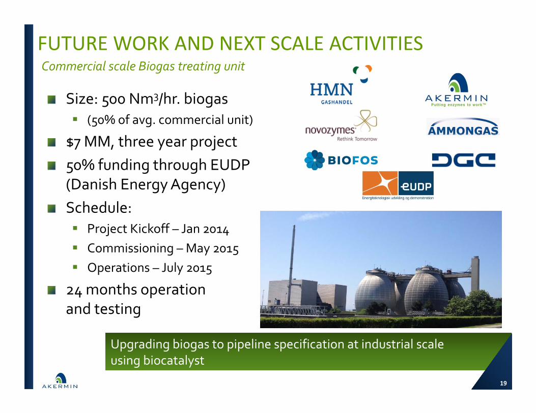
Size: 500 Nm3/hr. biogas (50% of avg. commercial unit)
$7 MM, three year project50% funding through EUDP (Danish Energy Agency)Schedule: Project Kickoff – Jan 2014 Commissioning – May 2015 Operations – July 2015
24 months operation and testing
Commercial scale Biogas treating unit
FUTURE WORK AND NEXT SCALE ACTIVITIES
Upgrading biogas to pipeline specification at industrial scale using biocatalyst
19
20 20
DOE/NETL: This material is based upon work supported by the Department of EnergyNational Energy Technology Laboratory under Award Numbers DE‐FE0004228 and DE‐FE0012862.
Disclaimer: This presentation was prepared as an account of work sponsored by anagency of the United States Government. Neither the United States Government norany agency thereof, nor any of their employees, makes any warranty, express orimplied, or assumes any legal liability or responsibility for the accuracy, completeness,or usefulness of any information, apparatus, product, or process disclosed, orrepresents that completeness, or usefulness of any information, apparatus, product, orprocess disclosed, or represents that its use would not infringe privately ownedrights. Reference herein to any specific commercial product, process, or service bytrade name, trademark, manufacturer, or otherwise does not necessarily constitute orimply its endorsement, recommendation, or favoring by the United States Governmentor any agency thereof. The views and opinions of authors expressed herein do notnecessarily state or reflect those of the United StatesGovernment or any agency.

21
ACKNOWLEDGMENTSUS DOE‐NETL Andrew Jones, Project ManagerNovozymes Generous supply of carbonic anhydrasePNNL Charles Freeman, Mark BeardenWorleyParsons Vladimir VaysmanEPIC Systems Pilot Unit fabricationEmerson Process Controls Controls and instrumentation
21