push - salice · the push-system is a self-opening system for the doors of all types of handleless...
TRANSCRIPT

Push


Catalogue index
Technical features page 28 94° opening for thicker doors page 30 110° opening page 32 155° opening page 34 155° opening for thicker doors page 36 Complementary hinges: for wooden doors with positive angled assembly page 38 crampon hinges page 40
Series 200
For metal profiles Practical System page 44 Series 200 page 47
Mechanical Push page 6 Retaining catches for wooden doors page 10 Retaining catches for aluminium-frame doors page 11 Adapters page 12 Spacers and insertion tool for retaining catch page 13 Assembly instructions and drillings page 14 Magnetic Push page 19 Adapters page 21 Assembly instructions page 22
PushPush to open system for handle-less doors
For glass doors Technical features page 52 110° opening page 53
For wooden doors Technical features page 54 110° opening page 56
Serie BHinges that need to be bonded to glass
Serie BHinges for half-inset doors or doors with moulded profiles
Accessories Screw cover caps page 60 Flange cover caps page 60 Spacers for Series 200 hinges page 60 Stop devices page 61
3

4

Mechanical Push
5

The PUSH-System is a self-opening system for the doors of all types of handleless furniture.
It consists of a series ofself-opening hinges, releasedevices that can be fitted to the top, base or side panel of the cabinet, and retaining catches to be fitted to the back of the door.
The retaining catches can be pressure-fixed or screw-fixed.
For doors over 1600 mm in height, we suggest that you use two mechanical release catches.
Mechanical Push
6

DP1SNB DP1SNG
Release devices with adhesive strip
PackingBoxes 300 pcs.
- beige - grey
Installation of mechanical Push with adhesive strip
For correct application and to ensure optimal endurance, please follow the following procedure:
1) clean and degrease the cabinet surface where the release device is to be installed using an acetone based cleaner;
2) remove the protective strip from the adhesive;
3) place the release device in position and apply a firm pressure for about one minute;
4) allow a period of 12 hours to elapse before subjecting the PUSH-System to continuous usage.
With assembly stop device
7

DP3SNB DP3SNG
DP3SNBR DP3SNGR
Mechanical Push - Release device to be screw-fixed
With assembly stop device
PackingBoxes 300 pcs.
- beige - grey
PackingBoxes 300 pcs.
- beige - grey Without assembly stop device
8

DP4SNB DP4SNG
DP5SNB DP5SNG
Release devices with adjustment
PackingBoxes 300 pcs.
PackingBoxes 150 pcs.
- beige Single adapter with depth and sideways adjustment and release device.Without assembly stop device.
Double adapter with depth and sideways adjustment and release devices.Without assembly stop device.
N.B.: Drilling patterns at page 14
Technical information on the adjustable mechanical Push
The adjustable Push consists of a release device and a screw-fixed adapter which have been developed to improve the locating action of the system.
The adjustable Push now has a depth adjustment facility with a range of -1 mm to + 2.5 mm which is controlled by a small adjuster wheel located at the back of the adapter.
In addition, the adapter has a sideways adjustment facility of ± 2 mm. This is achieved by loosening the two fixing screws and adjusting the position of the adapter using the elongated holes. Finally, the screws must be retightened.
- grey
- beige - grey
Without assembly stop device
9
DP29SNB DP29SNG
DP29SNBMC DP29SNGMC
DP29SNBI DP29SNGI
DP29SNBR DP29SNGR
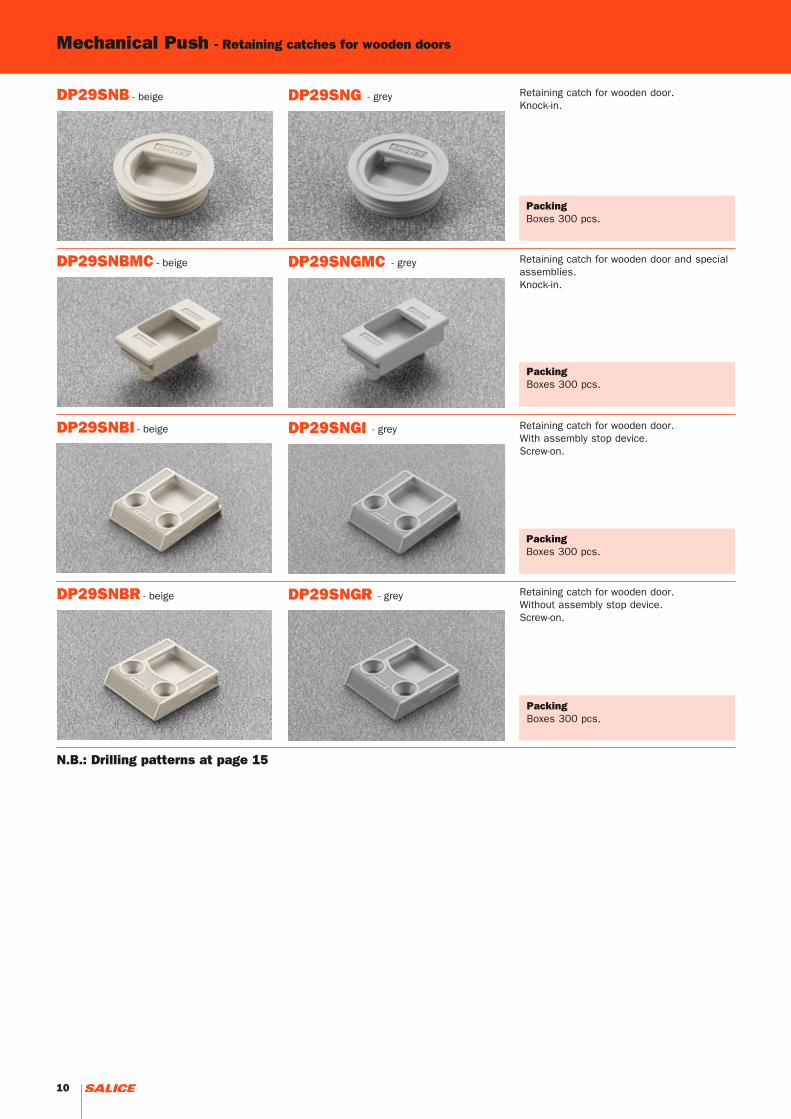
Mechanical Push - Retaining catches for wooden doors
PackingBoxes 300 pcs.
PackingBoxes 300 pcs.
- beige Retaining catch for wooden door.Knock-in.
Retaining catch for wooden door and special assemblies.Knock-in.
- grey
- beige - grey
PackingBoxes 300 pcs.
PackingBoxes 300 pcs.
- beige Retaining catch for wooden door. With assembly stop device.Screw-on.
Retaining catch for wooden door.Without assembly stop device.Screw-on.
- grey
- beige - grey
N.B.: Drilling patterns at page 15
10

DP29SNBA DP29SNGA
DP29SNBB DP29SNGB
DP29SNBP DP29SNGP
Retaining catches for aluminium-frame doors
PackingBoxes 300 pcs.
PackingBoxes 300 pcs.
- beige Retaining catch for aluminium-frame door width = 35 - 45 mm.
Retaining catch for aluminium-frame door width = 17 - 35 mm.
- grey
grey
PackingBoxes 300 pcs.
- beige Retaining catch for aluminium-frame door Practical.
- grey
N.B.: Drilling patterns at pages 16 and 17
- beige
11

DP52SNB DP52SNG
DP52SNBR DP52SNGR
DP54SNB DP54SNG
DP54SNBR DP54SNGR
Mechanical Push - Adapters
PackingBoxes 300 pcs.
PackingBoxes 300 pcs.
- beige Single adapter. 6x40 mm drilling.With assembly stop device.DP53SN_ = single adapter with sideways adjustment.
Single adapter.6x40 mm drilling.Without assembly stop device.DP53SN_R = single adapter with sideways adjustment.
- grey
- beige - grey
PackingBoxes 150 pcs.
PackingBoxes 150 pcs.
- beige Double adapter. 6x16 mm drilling.With assembly stop device.
Double adapter.6x16 mm drilling.Without assembly stop device.
- grey
- beige - grey
12
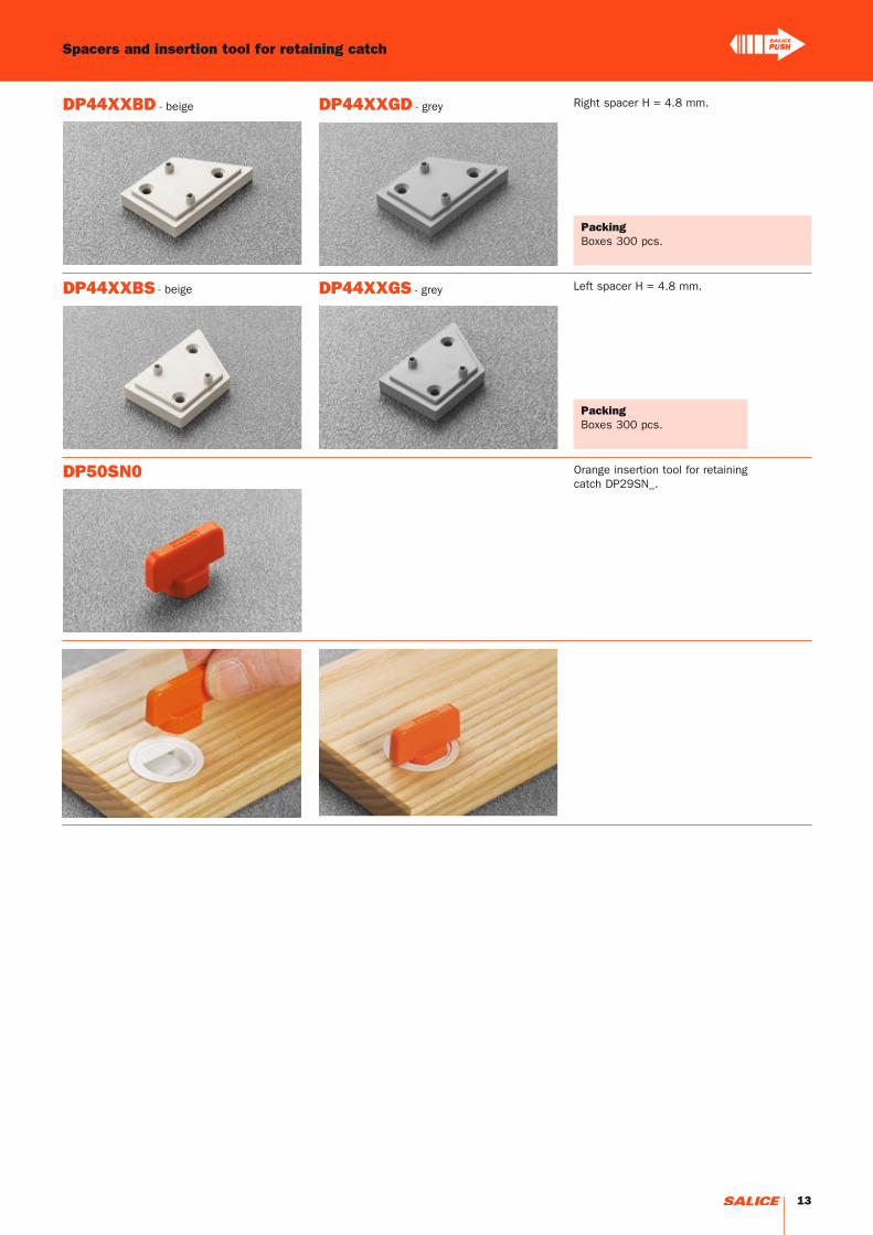
DP44XXBD DP44XXGD
DP44XXBS DP44XXGS
DP50SN0
Spacers and insertion tool for retaining catch
PackingBoxes 300 pcs.
PackingBoxes 300 pcs.
- beige Right spacer H = 4.8 mm.
Left spacer H = 4.8 mm.
- grey
- beige - grey
Orange insertion tool for retaining catch DP29SN_.
13
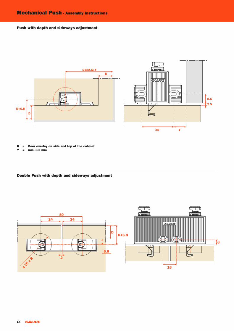
Mechanical Push - Assembly instructions
Push with depth and sideways adjustment
Double Push with depth and sideways adjustment
D = Door overlay on side and top of the cabinetY = min. 8.5 mm
14
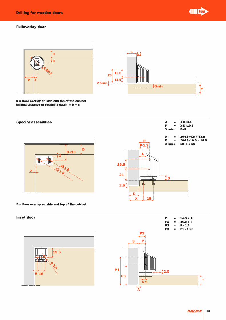
P = 14.8 + AP1 = 36.8 + TP2 = P - 1.3P3 = P1 - 16.5
A = X-D+4.5P = X-D+10.8X min= D+8
A = 26-18+4.5 = 12.5P = 26-18+10.8 = 18.8X min= 18+8 = 26
Drilling for wooden doors
Fulloverlay door
D = Door overlay on side and top of the cabinetDrilling distance of retaining catch = D + 8
Special assemblies
Inset door
D = Door overlay on side and top of the cabinet
15

Mechanical Push - Drilling for aluminium frame doors
Profile min. 35 mm/max. 45 mm
D = Door overlay on side and top of the cabinetF = Drilling distance of retaining catch = D + 8X = Relative to the distance to the corner of the profileP = Fixing distance of PUSH = X - D + 1.3
D = Door overlay on side and top of the cabinetF = Drilling distance of retaining catch = D + 8X = Relative to the distance to the corner of the profileP = Fixing distance of PUSH = X - D + 1.3
Profile min. 17 mm/max 35 mm
16

Profile with corner connector D206BS5
D = Door overlay on side and top of the cabinetP = Fixing distance of PUSH = 61 (min) - D + 1.3
Profile with corner connector D206BS5L
D = Door overlay on side and top of the cabinetP = Fixing distance of PUSH = 77 (min) - D + 1.3
Practical - Drilling for aluminium frame doors
17

18

Magnetic Push
19

DPMB289 DPMG289
DPMB3891 DPMG3891
DPAB289 DPAG289
DPAB3891 DPAG3891
Retaining catch to be inserted. ø 11.5 mm.
Retaining catch with adhesive. 20x14 mm.
Release device.ø 10 mm, 40 mm length.
PackingBoxes 250 pcs.Cartons 1.500 pcs.
PackingBoxes 250 pcs.Cartons 1.500 pcs.
Release device.ø 10 mm, 40 mm length.
Magnetic Push - Release device to be recessed and retaining catches
- beige - grey
- beige - beige - grey
Retaining catch to be inserted. ø 11.5 mm.
Retaining catch with adhesive. 20x14 mm.
Release device to be used to increase the magnetic holding strength. It must always be used together with the DPM. The suggested position of the DPM is the point of pressure on the door. The DPA can be positioned at any point along the opening edge of the door. ø 10 mm, 40 mm length.
PackingBoxes 250 pcs.Cartons 1.500 pcs.
PackingBoxes 250 pcs.Cartons 1.500 pcs.
Release device to be used to increase the magnetic holding strength. It must always be used together with the DPM. The suggested position of the DPM is the point of pressure on the door. The DPA can be positioned at any point along the opening edge of the door. ø 10 mm, 40 mm length.
- beige - grey
- beige - grey
20

DP80SNBR
DP85SNBR
DP84SNBR
DP82XXBR
DP80SNGR
DP85SNGR
DP84SNGR
DP82XXGR
DP80SNB DP80SNG
DP83XXBR DP83XXGR
Plastic adapter for release device.To be fixed with wood screws.7.5x32 mm drilling.Without assembly stop devices.DP81SN_R = To be fixed with Euroscrews.
Adjustable plastic adapter for release device. To be fixed with wood screws.37x32 mm drilling.
PackingBoxes 500 pcs.Pallets 12.000 pcs.
PackingBoxes 500 pcs.Pallets 12.000 pcs.
Adjustable plastic adapter for release device. To be fixed with wood screws.8x32 mm drilling.
Adjustable longitudinal plastic adapter for release device. To be fixed with wood screws.8+16 mm drilling.
Caps to be ordered separately.
PackingBoxes 500 pcs.Pallets 12.000 pcs.
PackingBoxes 500 pcs.Pallets 12.000 pcs.
Plastic adapter for release device.To be fixed with wood screws.7.5x32 mm drilling.With assembly stop devices.DP81SN_ = To be fixed with Euroscrews.
PackingBoxes 500 pcs.Pallets 12.000 pcs.
Adjustable double plastic adapter for release device. To be fixed with wood screws.8+32 mm drilling.
Cover caps to be ordered separately.
PackingBoxes 500 pcs.Pallets 12.000 pcs.
- beige - grey
- beige - grey
- beige - grey
- beige - grey
- beige - grey
- beige - grey
Adapters
21
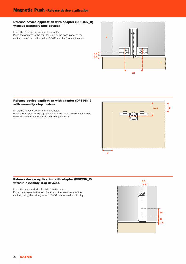
Release device application with adapter (DP80SN_) with assembly stop devices
Insert the release device into the adapter.Place the adapter to the top, the side or the base panel of the cabinet, using the assembly stop devices for final positioning.
Release device application with adapter (DP80SN_R) without assembly stop devices
Insert the release device into the adapter.Place the adapter to the top, the side or the base panel of the cabinet, using the drilling value 7.5x32 mm for final positioning.
Magnetic Push - Release device application
Release device application with adapter (DP82SN_R) without assembly stop devices.
Insert the release device frontally into the adapter.Place the adapter to the top, the side or the base panel of the cabinet, using the drilling value of 8+16 mm for final positioning.
22
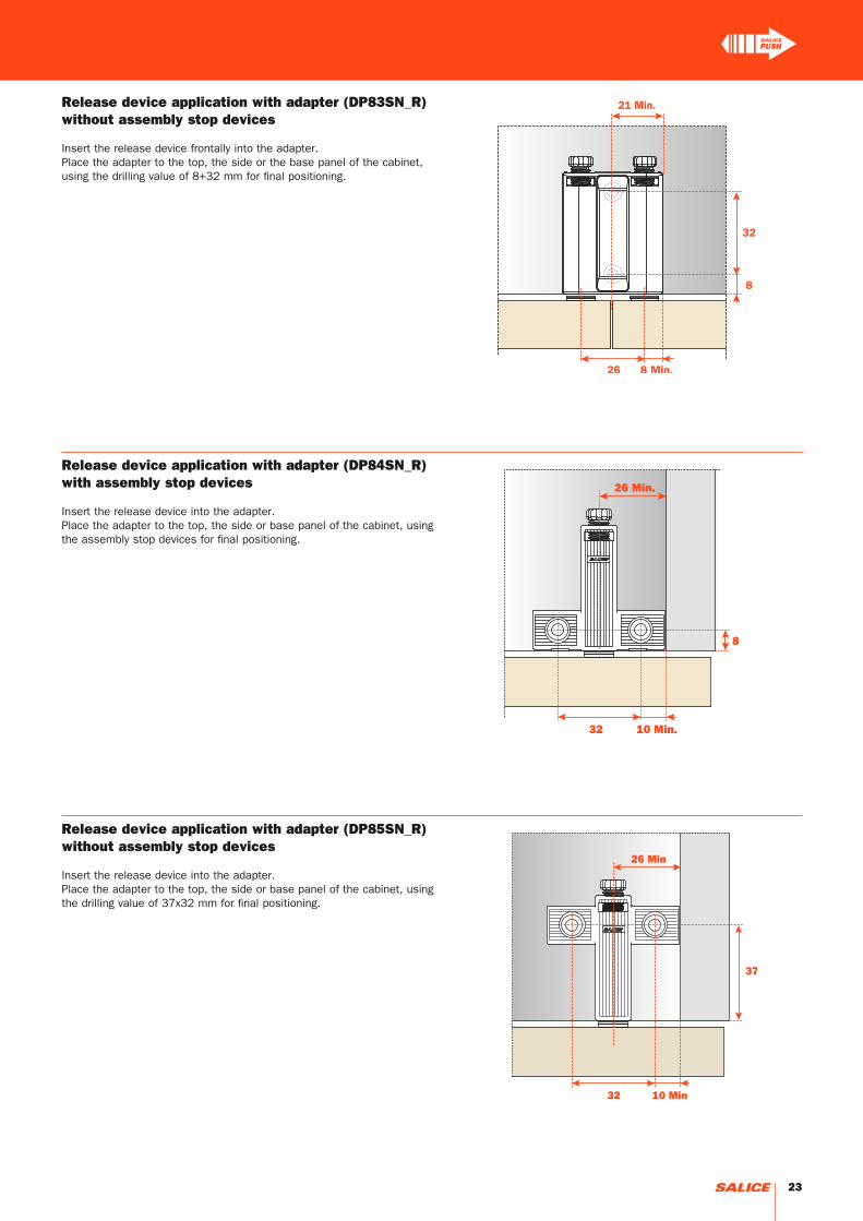
Release device application with adapter (DP84SN_R) with assembly stop devices
Insert the release device into the adapter.Place the adapter to the top, the side or base panel of the cabinet, using the assembly stop devices for final positioning.
Release device application with adapter (DP85SN_R) without assembly stop devices
Insert the release device into the adapter.Place the adapter to the top, the side or base panel of the cabinet, using the drilling value of 37x32 mm for final positioning.
Release device application with adapter (DP83SN_R) without assembly stop devices
Insert the release device frontally into the adapter.Place the adapter to the top, the side or the base panel of the cabinet, using the drilling value of 8+32 mm for final positioning.
23

Application of the release device to be recessed
Drill a hole Ø 10 mm and min. 40 mm depth in the top, the side or the base panel of the cabinet.Insert the release device into the hole.
Magnetic Push - Release device application
24

1 - Retaining catch with adhesive strip
Apply the retaining catch to the magnetic release device.Remove the protective strip from the adhesive.Close the door. In this way the retaining catch is positioned on the door.Reopen the door and apply a firm pressure to the retaining catch to ensure a correct installation.
ATTENTION:For a correct application and to ensure optimal endurance, we suggest these guidelines are followed:
1 - clean and degrease the door surface where the retaining catch is to be installed;2 - remove the protective strip from the adhesive;3 - place the retaining catch in position, in a place that is at room temperature ≥ 10° and apply a firm pressure for 10-15 seconds.
After few seconds from the installation the retaining catch is suitable for the use. After 24h the max. hold is attained.
2 - Retaining catch to be inserted
Apply the retaining catch to the magnetic release device.Close the door. The point of the retaining catch will show where to insert it.Reopen the door and press the retaining catch.
Retaining catch applicationlease device application
25

26

Push - Series 200 hinges
27

The Series 200 make up an integrated system of hinges developed to provide a solution to any situation involving concealed hinges.Bright nickel plated steel cup and arm.Dimensions of the ø 35 mm cup.
Constant “L” value of 0.7 mm (it does not change during side adjustment).
Approx. number of hinges required according to the door dimension and weight.
Width of the door Weight of the door (N)
Heig
ht o
f th
e d
oor
Adjustments
Compensating side adjustment from - 1.5 to + 4.5 mm.Height adjustment ± 2 mm.Depth adjustment with Series 200 mounting plates + 2.8 mm.Depth adjustment with Domi snap-on mounting plates from - 0.5 mm to + 2.8 mm.Anti-sliding safety stop.
Mounting plates
Symmetrical and asymmetrical bright nickel plated steel or die-cast Series 200 mounting plates.Snap-on assembly on Domi mounting plates .Positioning with pre-determined stop on traditional Series 200 mounting plates.
N.B. : Use POZIDRIVE No. 2 screwdrivers for all screws.
Push - Series 200 hinges Technical features
28

Logica
Drillings and fixings
Wood screw
Dowel
Rapido
Use this table to identify the available drillings and fixings. Fill the third position of the hinge code number with the letter or the number corresponding to your choice. I.e.: C2_PA99.
Fill this position with the chosen letter or number.
29

C = 23 + K + A
T= 19 20 21 22 23 24 25 26 27 28 29 30 31 32 33 34 35
K=3 A= 0.1 0.2 0.3 0.4 0.5 0.7 0.8 1.0 1.6 2.6 3.5 4.5 5.4 6.4 7.4 8.3 9.3
K=4 A= 0.1 0.2 0.3 0.4 0.5 0.7 0.8 1.0 1.2 1.9 2.8 3.8 4.7 5.7 6.6 7.6 8.6
K=5 A= 0.1 0.2 0.3 0.4 0.5 0.7 0.8 1.0 1.2 1.4 2.2 3.1 4.1 5.0 5.9 6.9 7.8
K=6 A= 0.1 0.2 0.3 0.4 0.5 0.6 0.8 1.0 1.2 1.4 1.7 2.6 3.5 4.4 5.3 6.2 7.2
K=7 A= 0.1 0.2 0.3 0.4 0.5 0.6 0.8 1.0 1.1 1.3 1.6 2.1 3.0 3.8 4.7 5.6 6.5
K=8 A= 0.1 0.2 0.3 0.4 0.5 0.6 0.8 0.9 1.1 1.3 1.6 1.8 2.5 3.3 4.2 5.1 6.0
K=9 A= 0.1 0.2 0.3 0.4 0.5 0.6 0.8 0.9 1.1 1.3 1.5 1.8 2.1 2.9 3.7 4.6 5.4
K= 3 4 5 6 7 8 9
L= 0.0 0.0 0.0 0.0 0.0 0.3 1.3
Push - Series 200 hinges - For thicker doors - 94° opening
Technical information
Push hinges are equipped with a special spring that acts to open the door independently of the release device.
For thick doors up to 35 mm, with special profiles. 11 mm deep metal cup.94° opening.Possible drilling distance on the door (K): from 3 to 9 mm.Compatible with all traditional Series 200 mounting platesand with all Domi snap-on mounting plates.
Space needed to open the door
Projection of the door
Projection of the door from the cabinet side at the max. opening. The figures are based on a straight arm hinge, H=0 mm thickness of mounting plate and K value = 3 mm.
“C” value
With this formula you can obtain the max. thickness of the moulded door that can be opened without touching adjacent carcase sides, doors or walls, whilst bearing in mind the above L-K-T values.
The above values are calculated on the assumption that the doors have square edges.They are reduced if the doors have radiussed edges.
30

H= 15 + K - (D)
H= 6 + K - (D)
H= -2 + K + A
H= 10 + K - (D)
C2_VA99
C2_VG99
C2_VP99
C2_VD99
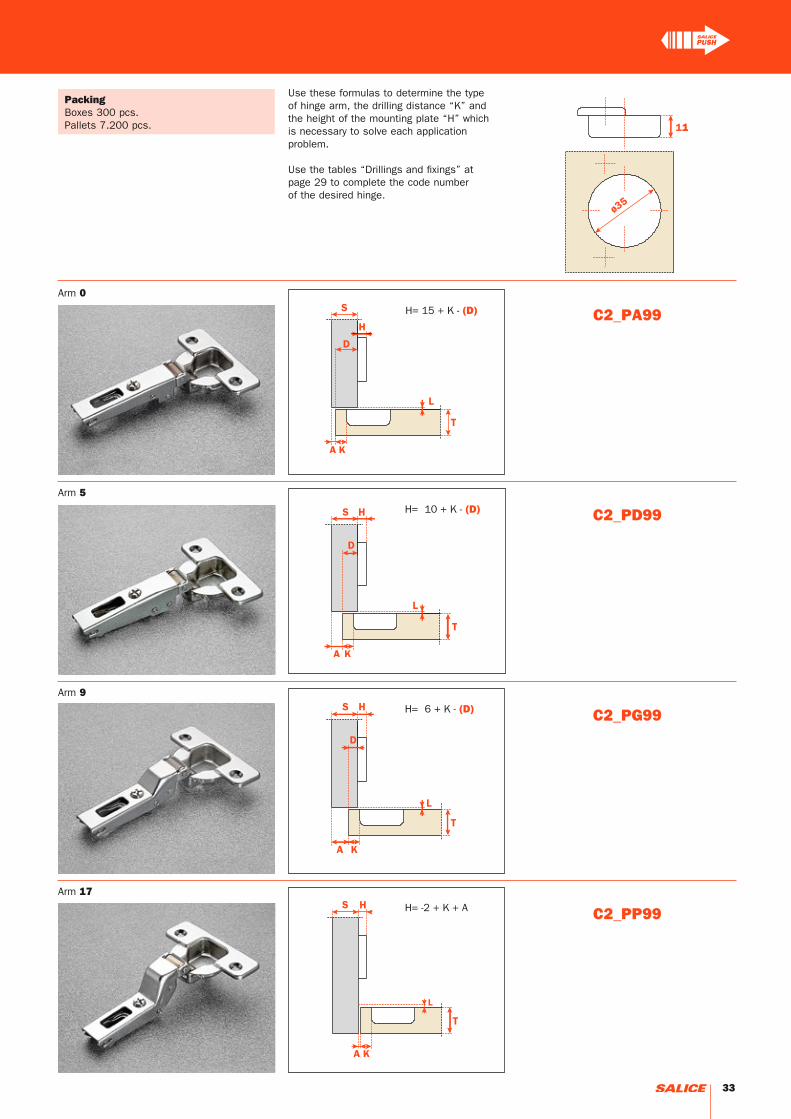
Use these formulas to determine the type of hinge arm, the drilling distance “K” and the height of the mounting plate “H” which is necessary to solve each application problem.
Use the tables “Drillings and fixings” at page 29 to complete the code number of the desired hinge.
PackingBoxes 300 pcs.Pallets 7.200 pcs.
Arm 0
Arm 9
Arm 17
Arm 5
31

C = 20 + K + A
T= 16 17 18 19 20 21 22 23 24 25 26
K=3 A= 0.5 0.7 0.9 1.2 1.5 1.8 2.4 3.7 5.1 6.5 7.8
K=4 A= 0.5 0.7 0.9 1.2 1.5 1.8 2.1 2.7 4.1 5.5 6.8
K=5 A= 0.5 0.7 0.9 1.2 1.5 1.8 2.1 2.6 3.1 4.1 5.4
K=6 A= 0.5 0.7 0.9 1.2 1.5 1.8 2.1 2.5 3.0 3.5 4.4
T= 16 17 18 19 20 21 22 23 24 25 26
K=3 L= 0.0 0.0 0.0 0.0 0.2 0.5 0.8 1.1 1.4 1.7 1.9
K=4 L= 0.0 0.0 0.3 0.6 0.9 1.2 1.4 1.7 2.0 2.3 2.6
K=5 L= 1.1 1.3 1.6 1.8 2.1 2.3 2.6 2.9 3.1 3.4 3.6
K=6 L= 2.0 2.3 2.5 2.8 3.1 3.3 3.6 3.8 4.1 4.3 4.6
Push - Series 200 hinges - 110° opening
Technical information
Push hinges are equipped with a special spring that acts to open the door independently of the release device.
When a greater opening angle is required.11 mm deep metal cup.110° opening.Possible drilling distance on the door (K): from 3 to 6 mm.Compatible with all traditional Series 200 mounting plates and with all Domi snap-on mounting plates.
Space needed to open the door
Projection of the door
Projection of the door from the cabinet side at the max. opening. The figures are based on a straight arm hinge, H=0 mm thickness of mounting plate and K value = 3 mm.
“C” value
With this formula you can obtain the max. thickness of the moulded door that can be opened without touching adjacent carcase sides, doors or walls, whilst bearing in mind the above L-K-T values.
The above values are calculated on the assumption that the doors have square edges.They are reduced if the doors have radiussed edges.
32
H= 15 + K - (D)
H= 6 + K - (D)
H= -2 + K + A
H= 10 + K - (D)
C2_PA99
C2_PG99
C2_PP99
C2_PD99
Use these formulas to determine the type of hinge arm, the drilling distance “K” and the height of the mounting plate “H” which is necessary to solve each application problem.
Use the tables “Drillings and fixings” at page 29 to complete the code number of the desired hinge.
PackingBoxes 300 pcs.Pallets 7.200 pcs.
Arm 0
Arm 9
Arm 17
Arm 5
33

T= 16 18 20 22
K=3 A= 0.0 0.0 0.3 1.2
K=4 A= 0.0 0.4 0.4 1.3
K=5 A= 0.0 0.1 0.5 1.6
K=6 A= 0.0 0.1 1.2 3.0
K=7 A= 0.0 0.1 0.7 2.5
K=8 A= 0.0 0.1 0.6 1.9
Push - Series 200 hinges - 155° opening
Technical information
Push hinges are equipped with a special spring that acts to open the door independently of the release device.
For thick doors min. 10 mm.8 mm deep die-cast cup.With 0 mm door protrusion only with straight arm hinge.155° opening.Possible drilling distance on the door (K): from 3 to 8 mm.Compatible with all traditional Series 200 mounting plates and with all Domi snap-on mounting plates.
Space needed to open the door
“C” value
For spaces with removable components. The door opens at 90° with lateral door protrusion of 2 mm. The figures are based on a straight arm hinge and H=0 thickness of mounting plate.
The above values are calculated on the assumption that the doors have square edges.They are reduced if the doors have radiussed edges.
34
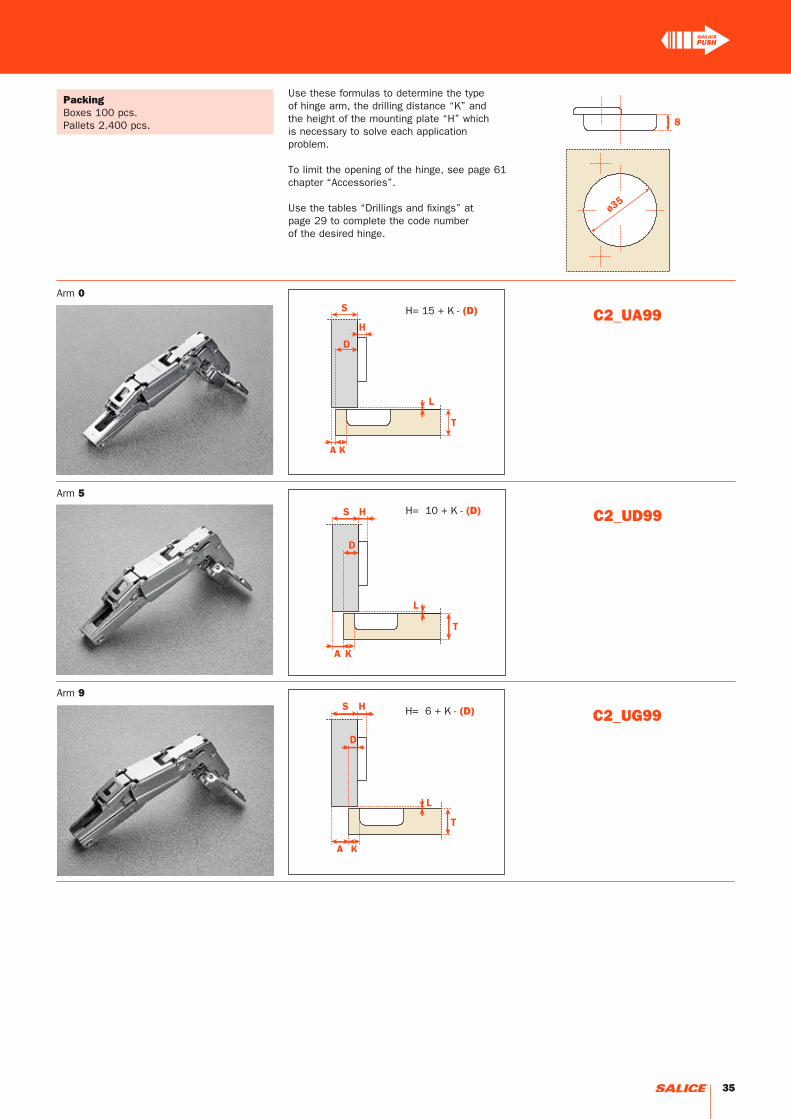
H= 15 + K - (D) C2_UA99
H= 6 + K - (D) C2_UG99
H= 10 + K - (D) C2_UD99
Use these formulas to determine the type of hinge arm, the drilling distance “K” and the height of the mounting plate “H” which is necessary to solve each application problem.
To limit the opening of the hinge, see page 61 chapter “Accessories”.
Use the tables “Drillings and fixings” at page 29 to complete the code number of the desired hinge.
PackingBoxes 100 pcs.Pallets 2.400 pcs.
Arm 0
Arm 5
Arm 9
35
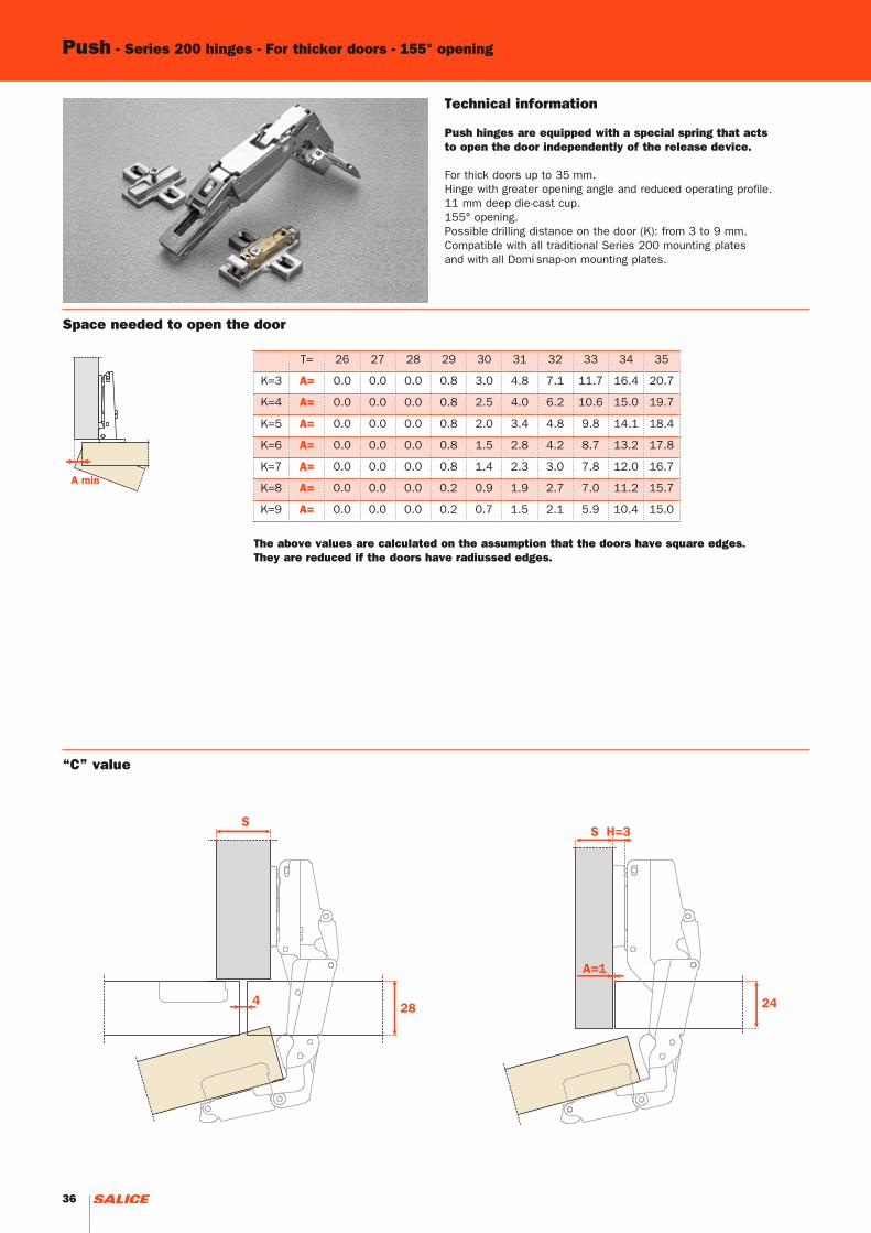
T= 26 27 28 29 30 31 32 33 34 35
K=3 A= 0.0 0.0 0.0 0.8 3.0 4.8 7.1 11.7 16.4 20.7
K=4 A= 0.0 0.0 0.0 0.8 2.5 4.0 6.2 10.6 15.0 19.7
K=5 A= 0.0 0.0 0.0 0.8 2.0 3.4 4.8 9.8 14.1 18.4
K=6 A= 0.0 0.0 0.0 0.8 1.5 2.8 4.2 8.7 13.2 17.8
K=7 A= 0.0 0.0 0.0 0.8 1.4 2.3 3.0 7.8 12.0 16.7
K=8 A= 0.0 0.0 0.0 0.2 0.9 1.9 2.7 7.0 11.2 15.7
K=9 A= 0.0 0.0 0.0 0.2 0.7 1.5 2.1 5.9 10.4 15.0
Push - Series 200 hinges - For thicker doors - 155° opening
Technical information
Push hinges are equipped with a special spring that acts to open the door independently of the release device.
For thick doors up to 35 mm.Hinge with greater opening angle and reduced operating profile.11 mm deep die-cast cup.155° opening.Possible drilling distance on the door (K): from 3 to 9 mm.Compatible with all traditional Series 200 mounting platesand with all Domi snap-on mounting plates.
Space needed to open the door
The above values are calculated on the assumption that the doors have square edges.They are reduced if the doors have radiussed edges.
“C” value
36

H= 15 + K - (D)
H= 6 + K - (D)
H= 10 + K - (D)
C2_TA99
C2_TG99
C2_TD99
Use these formulas to determine the type of hinge arm, the drilling distance “K” and the height of the mounting plate “H” which is necessary to solve each application problem.
To limit the opening of the hinge, see page 61 chapter “Accessories”.
Use the tables “Drillings and fixings” at page 29 to complete the code number of the desired hinge.
PackingBoxes 100 pcs.Pallets 2.400 pcs.
Arm 0
Arm 9
Arm 5
37

C2_VU99
C2_VE99
C2_VZ99
Push - Series 200 hinges - Complementary hinges
The solution of assembly problems where doors are mounted at a positive angle requires the verification of drilling distances by a practical trial. Please do not hesitate to consult our technical support department for assistance.
Use the tables “Drillings and fixings” at page 29 to complete the code number of the desired hinge.
PackingBoxes 150 pcs.Pallets 3.600 pcs.
Technical information
Push hinges are equipped with a special spring that acts to open the door independently of the release device.
Hinges for wooden doors with positive angled assembly.11 mm deep metal cup.94° opening.Possible drilling distance on the door (K): from 3 to 9 mm.Compatible with all traditional Series 200 mounting plates and with all Domi snap-on mounting plates.
Arm 24°
Arm 30°
Arm 15°
38
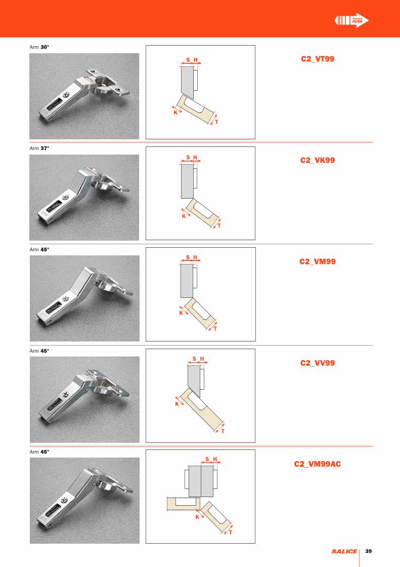
C2_VK99
C2_VV99
C2_VM99AC
C2_VM99
C2_VT99
Arm 37°
Arm 45°
Arm 45°
Arm 45°
Arm 30°
39

C2_VN99AC
H = 0 H = 3 H = 6
* A=1 K=3
Technical information
Push hinges are equipped with a special spring that acts to open the door independently of the release device.
Crampon hinges.For cabinet sides with 37x32 mm standard drilling.11 mm deep metal cup.94° opening.Possible drilling distance on the door (K): from 3 to 9 mm.Compatible with all traditional Series 200 mounting plates and with all Domi snap-on mounting plates.
E min: 61 mm for Series 200 mounting plates.70 mm for Domi snap-on mounting plates.74 mm for Domi snap-on mounting plates with back cam.
Use the tables “Drillings and fixings” at page 29 to complete the code number of the desired hinge.
PackingBoxes 150 pcs.Pallets 3.600 pcs.
Heights of mounting plates for every assembly.
Push - Series 200 hinges - Complementary hinges
40

C2_VN99
H = 0 H = 9 H = 12
* A=1 K=3
Technical information
Push hinges are equipped with a special spring that acts to open the door independently of the release device.
Crampon hinges.For smaller spaces with 15x32 mm drilling.11 mm deep metal cup.94° opening.Possible drilling distance on the door (K): from 3 to 9 mm.Compatible with all traditional Series 200 mounting plates, 28x32 mm drilling.NOT COMPATIBLE with Domi snap-on mounting plates.
Use the tables “Drillings and fixings” at page 29 to complete the code number of the desired hinge.
PackingBoxes 150 pcs.Pallets 3.600 pcs.
Heights of mounting plates for every assembly.
41

42
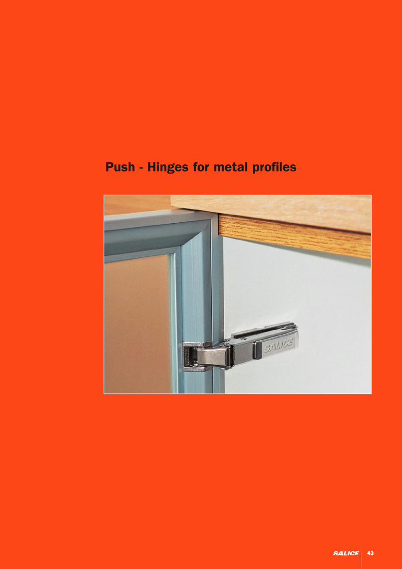
Push - Hinges for metal profiles
43

H= 6 + 6 - (D)
H= -2 + 6 + A
H= 10 + 6 - (D)
C20PA99
C20PG99
C20PP99
C20PD99
H= 15 + 6 - (D)
Technical information
Push hinges are equipped with a special spring that acts to open the door independently of the release device.
Hinges for the Practical system have been developed for use with special metal profiles. The particular fixing system does not require any profile working. The hinge can be therefore assembled at any point of the frame.105° opening.Compatible with all traditional Series 200 mounting plates and with all Domi snap-on mounting plates.
PackingBoxes 150 pcs.Pallets 3.600 pcs.
Arm 0
Arm 9
Arm 17
Arm 5
Push - Practical hinges - 105° opening
44
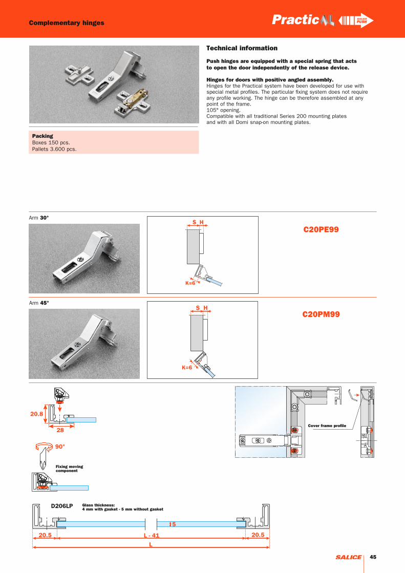
C20PE99
C20PM99
Technical information
Push hinges are equipped with a special spring that acts to open the door independently of the release device.
Hinges for doors with positive angled assembly.Hinges for the Practical system have been developed for use with special metal profiles. The particular fixing system does not require any profile working. The hinge can be therefore assembled at any point of the frame.105° opening.Compatible with all traditional Series 200 mounting plates and with all Domi snap-on mounting plates.
Complementary hinges
PackingBoxes 150 pcs.Pallets 3.600 pcs.
Arm 30°
Arm 45°
Fixing moving component
Glass thickness:4 mm with gasket - 5 mm without gasket
Cover frame profile
45
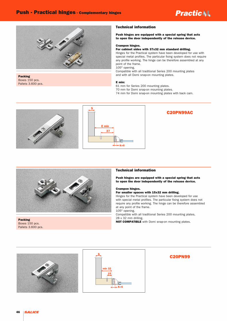
C20PN99AC
C20PN99
PackingBoxes 150 pcs.Pallets 3.600 pcs.
Technical information
Push hinges are equipped with a special spring that acts to open the door independently of the release device.
Crampon hinges.For cabinet sides with 37x32 mm standard drilling.Hinges for the Practical system have been developed for use with special metal profiles. The particular fixing system does not require any profile working. The hinge can be therefore assembled at any point of the frame.105° opening.Compatible with all traditional Series 200 mounting plates and with all Domi snap-on mounting plates.
E min: 61 mm for Series 200 mounting plates.70 mm for Domi snap-on mounting plates. 74 mm for Domi snap-on mounting plates with back cam.
PackingBoxes 150 pcs.Pallets 3.600 pcs.
Technical information
Push hinges are equipped with a special spring that acts to open the door independently of the release device.
Crampon hinges.For smaller spaces with 15x32 mm drilling.Hinges for the Practical system have been developed for use with special metal profiles. The particular fixing system does not require any profile working. The hinge can be therefore assembled at any point of the frame.105° opening.Compatible with all traditional Series 200 mounting plates,28 x 32 mm drilling.NOT COMPATIBLE with Domi snap-on mounting plates.
Push - Practical hinges - Complementary hinges
46
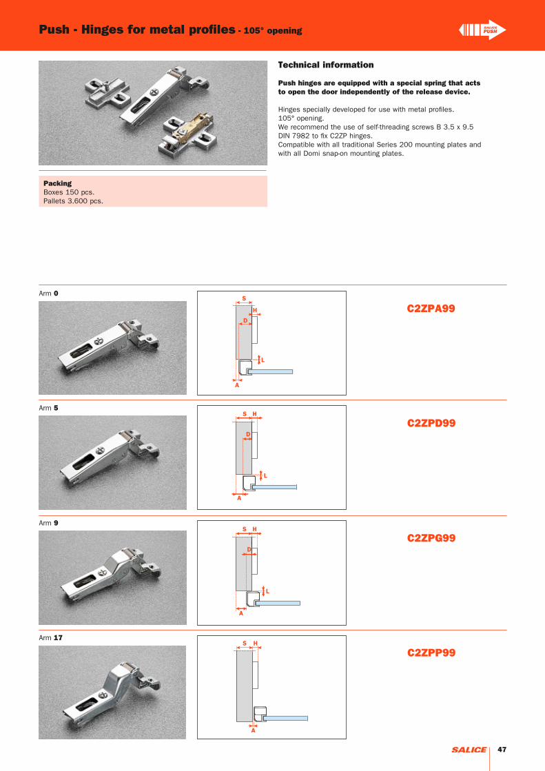
C2ZPA99
C2ZPG99
C2ZPP99
C2ZPD99
Push - Hinges for metal profiles - 105° opening
Technical information
Push hinges are equipped with a special spring that acts to open the door independently of the release device.
Hinges specially developed for use with metal profiles.105° opening.We recommend the use of self-threading screws B 3.5 x 9.5 DIN 7982 to fix C2ZP hinges.Compatible with all traditional Series 200 mounting plates and with all Domi snap-on mounting plates.
PackingBoxes 150 pcs.Pallets 3.600 pcs.
Arm 0
Arm 9
Arm 17
Arm 5
47

C2ZPE99
C2ZPM99
W = min. 17 mm max. 24 mm
Push - Hinges for metal profiles - Complementary hinges
Arm 30°
Arm 45°
PackingBoxes 150 pcs.Pallets 3.600 pcs.
Technical information
Push hinges are equipped with a special spring that acts to open the door independently of the release device.
Hinges for doors with positive angled assembly.Hinges specially developed for use with metal profiles.105° opening.We recommend the use of self-threading screws B 3.5 x 9.5 DIN 7982 to fix C2ZP hinges.Compatible with all traditional Series 200 mounting plates and with all Domi snap-on mounting plates.
48
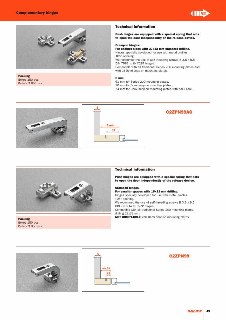
C2ZPN99AC
C2ZPN99
PackingBoxes 150 pcs.Pallets 3.600 pcs.
Technical information
Push hinges are equipped with a special spring that acts to open the door independently of the release device.
Crampon hinges.For cabinet sides with 37x32 mm standard drilling.Hinges specially developed for use with metal profiles.105° opening.We recommed the use of self-threading screws B 3.5 x 9.5DIN 7982 to fix C2ZP hinges.Compatible with all traditional Series 200 mounting plates and with all Domi snap-on mounting plates.
E min: 61 mm for Series 200 mounting plates.70 mm for Domi snap-on mounting plates. 74 mm for Domi snap-on mounting plates with back cam.
PackingBoxes 150 pcs.Pallets 3.600 pcs.
Technical information
Push hinges are equipped with a special spring that acts to open the door independently of the release device.
Crampon hinges.For smaller spaces with 15x32 mm drilling.Hinges specially developed for use with metal profiles.105° opening.We recommed the use of self-threading screws B 3.5 x 9.5 DIN 7982 to fix C2ZP hinges.Compatible with all traditional Series 200 mounting plates, drilling 28x32 mm.NOT COMPATIBLE with Domi snap-on mounting plates.
Complementary hinges
49

50

Push - Series B hinges
51

Push - Series B hinges for glass doors
No drilling of the glass is required.Bright nickel plated die-cast cup and arm.
Constant “L” value of 0.7 mm (it does not change during side adjustment).
Approx. number of hinges required according to the door dimension and weight.
Width of the door Weight of the door (N)
Heig
ht o
f th
e d
oor
Adjustments
Compensated side adjustment from -1.5 mm to +4.5 mm.Height adjustment ±2 mm.Depth adjustment with Series 200 mounting plates +2.8 mm.Depth adjustment with Domi snap-on mounting plates from -0.5 mm to +2.8 mm.Anti-sliding safety stop.
Mounting plates
Symmetrical and asymmetrical bright nickel plated steel or die-cast Series 200 mounting plates.Snap-on assembly on Domi mounting plates.Positioning with pre-determined stop on traditional Series 200 mounting plates.
N.B. : Use POZIDRIVE No. 2 screwdrivers for all screws.
Disclaimer
Salice Series B (CBG) hinges have been developed for use on glass doors and mirrors. Salice will accept no responsibility for any problems associated with the type of adhesive or method of application when used in conjunction with Series B hinges, nor for any consequences of the incorrect mounting of the door. It is recommended that the selected adhesive is subjected to prior testing. The adhesive may be considered appropriate if the plate, when fixed to the glass, can sustain a minimum torsion load of 160 Nm.
Technical features
52
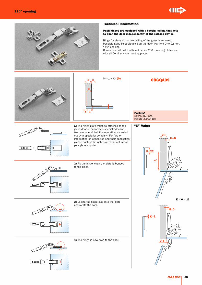
H= -1 + K - (D)
46
CBGQA99
K = 0 - 22
110° opening
Technical information
Push hinges are equipped with a special spring that acts to open the door independently of the release device.
Hinge for glass doors. No drilling of the glass is required.Possible fixing inset distance on the door (K): from 0 to 22 mm.110° opening.Compatible with all traditional Series 200 mounting plates and with all Domi snap-on monting plates.
PackingBoxes 150 pcs.Pallets 3.600 pcs.
1) The hinge plate must be attached to the glass door or mirror by a special adhesive. We recommend that this operation is carried out by a specialist company. For further information on adhesives and their application, please contact the adhesive manufacturer or your glass supplier.
2) Fix the hinge when the plate is bonded to the glass.
3) Locate the hinge cup onto the plate and rotate the cam.
4) The hinge is now fixed to the door.
“C” Value
53

Series B hinges can provide a solution to a number of special applications, which include half-inset doors and doors with moulded profiles.Dimensions of the 35 mm cup.Bright nickel plated die-cast cup and arm.
Constant “L” value of 0.7 mm (it does not change during side adjustment).
Approx. number of hinges required according to the door dimension and weight.
Width of the door Weight of the door (N)
Heig
ht o
f th
e d
oor
Push - Series B hinges for wooden doors
Technical features
Adjustments
Compensated side adjustment from -1.5 mm to +4.5 mm.Height adjustment ±2 mm.Depth adjustment with Series 200 mounting plates +2.8 mm.Depth adjustment with Domi snap-on mounting plates from -0.5 mm to +2.8 mm.Anti-sliding safety stop.
Mounting plates
Symmetrical and asymmetrical bright nickel plated steel or die-cast Series 200 mounting plates.Snap-on assembly on Domi mounting plates.Positioning with pre-determined stop on traditional Series 200 mounting plates.
N.B. : Use POZIDRIVE No. 2 screwdrivers for all screws.
54
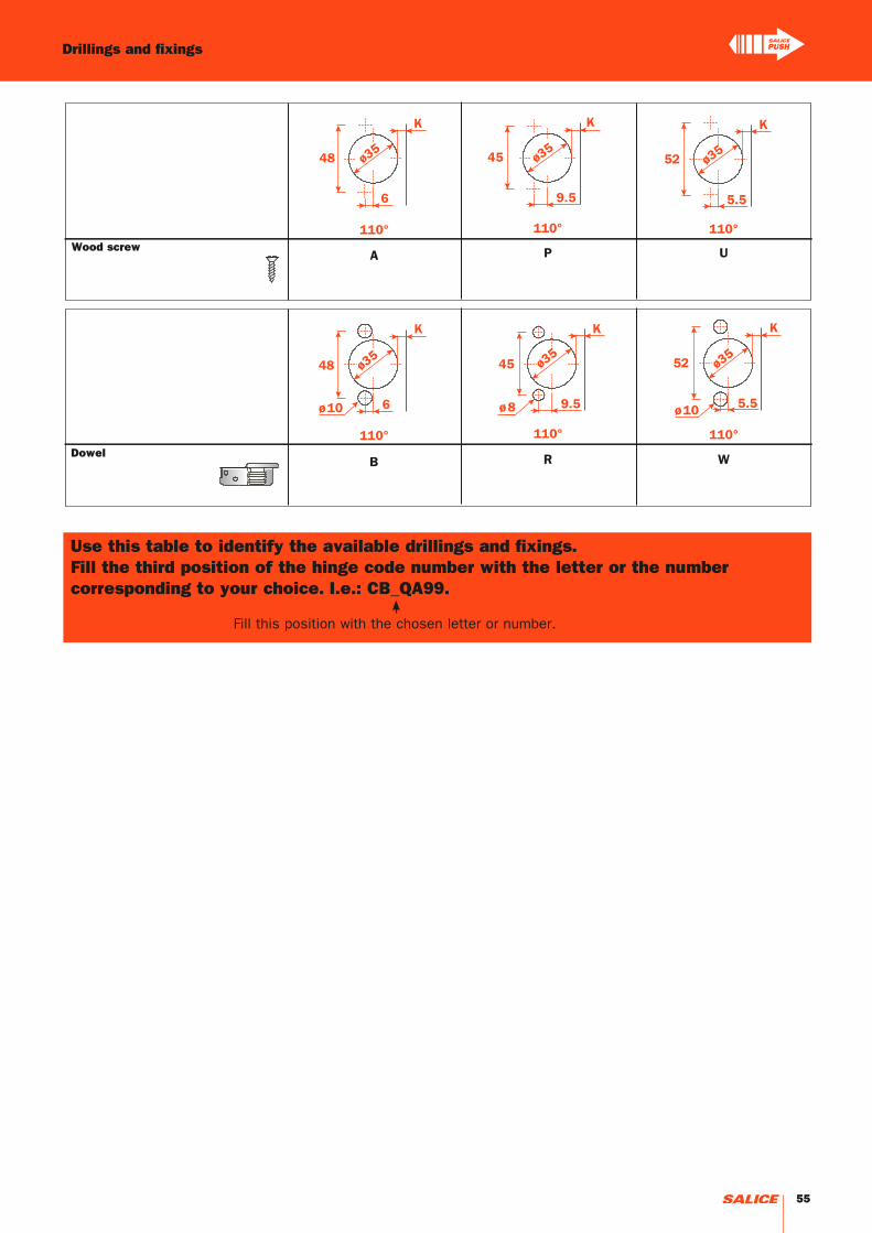
Drillings and fixings
Wood screw
Dowel
Use this table to identify the available drillings and fixings. Fill the third position of the hinge code number with the letter or the number corresponding to your choice. I.e.: CB_QA99.
Fill this position with the chosen letter or number.
55

C = 5.5 + K + A
T= 16 18 20 22 24 26
K=3 A= 0.0 0.0 0.0 0.0 0.3 1.4
K=4 A= 0.0 0.0 0.0 0.0 0.4 1.5
K=5 A= 0.0 0.0 0.0 0.0 0.5 1.9
K=6 A= 0.0 0.0 0.0 0.0 0.7 2.6
K=7 A= 0.0 0.0 0.0 0.0 11,3 12.8
K=8 A= 0.0 0.0 0.0 0.0 10.3 12.9
K=9 A= 0.0 0.0 0.0 0.0 9.3 11.9
K=10 A= 0.0 0.0 0.0 6.0 8.3 10.9
K=11 A= 0.0 0.0 0.0 5.1 7.3 9.9
K=12 A= 0.0 0.0 0.0 4.1 6.3 8.9
K=13 A= 0.0 0.0 1.4 3.3 5.3 7.9
K=14 A= 0.0 0.0 0.7 2.6 4.5 6.9
K=15 A= 0.0 0.0 0.2 2.0 3.8 5.9
K=16 A= 0.0 0.0 0.0 1.4 3.2 5.0
K=17 A= 0.0 0.0 0.0 1.0 2.7 4.4
K=18 A= 0.0 0.0 0.0 0.7 2.2 3.9
Push - Series B hinges - For wooden doors - 110° opening
Technical information
Push hinges are equipped with a special spring that acts to open the door independently of the release device and can provide a solution to a number of special applications, which include half-inset doors and doors with moulded profiles.
9 mm deep metal cup.110° opening.Possible drilling distance on the door (K): from 3 to 18 mm.Compatible with all traditional Series 200 mounting plates and with all Domi snap-on mounting plates.
Space needed to open the door
Projection of the door
Projection of the door from the cabinet side at the max. opening. The figures are based on a straight arm hinge, H=0 mm thickness of mounting plate and K value = 3 mm.
“C” value
With this formula you can obtain the max. thickness of the moulded door that can be opened without touching adjacent carcase sides, doors or walls, whilst bearing in mind the above L-K-T values.
The above values are calculated on the assumption that the doors have square edges.They are reduced if the doors have radiussed edges.
56
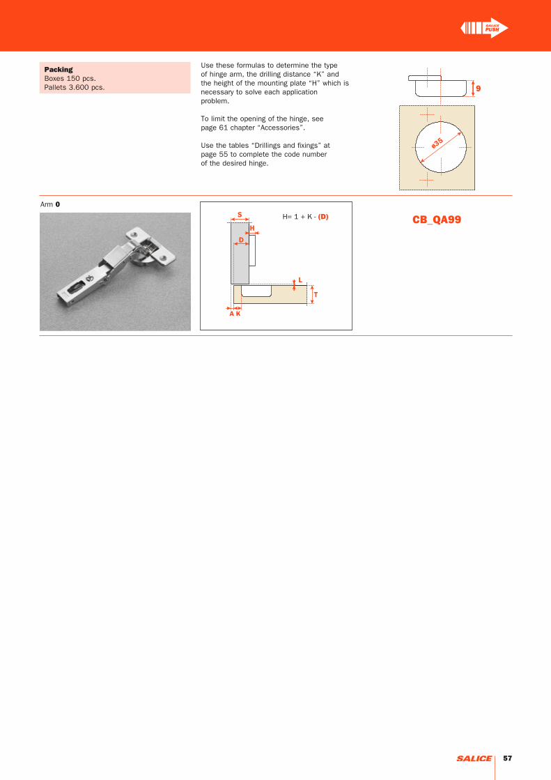
H= 1 + K - (D) CB_QA99
9
Use these formulas to determine the type of hinge arm, the drilling distance “K” and the height of the mounting plate “H” which is necessary to solve each application problem.
To limit the opening of the hinge, see page 61 chapter “Accessories”.
Use the tables “Drillings and fixings” at page 55 to complete the code number of the desired hinge.
PackingBoxes 150 pcs.Pallets 3.600 pcs.
Arm 0
57

58

Accessories
59
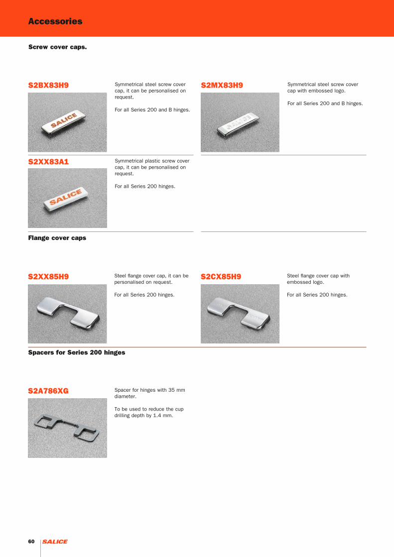
S2XX83A1
S2BX83H9 S2MX83H9
S2CX85H9S2XX85H9
S2A786XG
Accessories
Symmetrical plastic screw cover cap, it can be personalised on request.
For all Series 200 hinges.
Symmetrical steel screw cover cap, it can be personalised on request.
For all Series 200 and B hinges.
Symmetrical steel screw cover cap with embossed logo.
For all Series 200 and B hinges.
Screw cover caps.
Steel flange cover cap with embossed logo.
For all Series 200 hinges.
Steel flange cover cap, it can be personalised on request.
For all Series 200 hinges.
Flange cover caps
Spacer for hinges with 35 mm diameter.
To be used to reduce the cup drilling depth by 1.4 mm.
Spacers for Series 200 hinges
60

S2A637XF
S2AF37X3
S2BF37XY
SBA237XG
Stop device
For all hinges with 94° opening and 35 mm cup diameter, it limits opening at 86°.
Stop device
For 155° hinges, it limits opening at 125°.
Stop devices
Stop device For 155° hinges, it limits opening at 115°.
Stop device
For Series B hinges it limits opening at 90°.
Accessories
61

Notes
62

63

Ed.
08
- 0
4/2
01
3
ARTURO SALICE S.p.A.VIA PROVINCIALE NOVEDRATESE, 1022060 NOVEDRATE (COMO) ITALIATEL. 031 790424FAX 031 [email protected]
DEUTSCHE SALICE GMBHRUDOLF DIESEL STR. 10 POSTFACH 1154 74382 NECKARWESTHEIMTEL. 07133 9807-0FAX. 07133 [email protected]
DEUTSCHE SALICE GMBHVERKAUFSBÜRO NORDRINGSTRASSE 36/A30 CENTER32584 LÖHNETEL. 05731 15608-0FAX. 05731 [email protected]
SALICE FRANCE S.A.R.L.ROUTE DE GOA ZAC LES 3 MOULINS06600 ANTIBESTEL. 0493 330069FAX. 0493 [email protected]
SALICE ESPAÑA, S.L.U.CALLE COPÉRNICO, 11POLÍGONO INDUSTRIAL COLL DE LA MANYA08403 GRANOLLERS (BARCELONA)TEL. 938 46 88 61FAX 938 49 11 [email protected]
SALICE UK LTD.KINGFISHER WAYHINCHINGBROOKE BUSINESS PARKHUNTINGDON CAMBS PE 29 6FNTEL. 01480 413831 FAX. 01480 [email protected]
SALICE AMERICA INC.2123 CROWN CENTRE DRIVECHARLOTTE NC. 28227TEL. 704 8417810FAX. 704 [email protected]
SALICE CANADA INC.4025 SLADEVIEW CRESCENTUNIT # 7-9MISSISSAUGA, ONTARIO L5L 5Y1TEL. 905 8208787 FAX. 905 [email protected]
We reserve the right to change technical specifications without notice.