purdue aerial robotics 2017 journal paper for auvsi … · purdue aerial robotics 2017 journal...
TRANSCRIPT

Purdue Aerial Robotics 2017
Journal Paper for AUVSI Student UAS Competition
Abstract
This paper describes the Purdue Aerial Robotics UAS for use in the AUVSI SUAS competition. As a
member committee of Purdue’s IEEE branch, Aerial Robotics has a heavy focus on low level design, with a
student-built flight controller, printed circuit board, and fixed wing aircraft. The aircraft itself is designed to be
sturdy and easily controllable, while the flight controller provides robust control of the plane’s flight path. A
coprocessor on the main control board allows for safety pilot takeover regardless of the status of the
autopilot, and is controlled directly by the safety pilot rather than via a laptop mission planner. The Ground
Control Station is also student-developed and has most of the features available to a commercial GCS,
including point-and-click waypoint generation. The video processing station is an efficient standard object
identifier run almost entirely from a raspberry pi mounted on the UAV. It has the ability to correctly identify
shapes, characters, and colors by name along with an object’s relative image location and orientation.

Purdue University - Purdue Aerial Robotics
2
Contents
1. Systems Engineering Approach 3
1.1 Mission Requirement Analysis 3
1.2 Design Rationale 4
1.3 Programmatic Risks & Mitigations 5
2. System Design 6
2.1 Aircraft 6
2.2 Autopilot 8
2.3 Obstacle Avoidance 13
2.4 Imaging System 13
2.5 Object Detection, Classification, Localization 13
2.6 Communications 15
2.7 Cyber-Security 16
3. Test and Evaluation Plan 16
3.1 Developmental Testing 16
3.2 Individual Component Testing 17
3.3 Mission Testing Plan 19
4. Safety, Risks, and Mitigation 19
4.1 Developmental Risks and Mitigations 19
4.2 Mission Risks and Mitigations 19
4.3 Operational Risks and Mitigations 20

Purdue University - Purdue Aerial Robotics
3
1. Systems Engineering Approach
The development of the UAS begins with understanding the subsystem requirements for each competition task. Electrical and hardware requirements were developed for the needed hardware and performance specifications to satisfy the basic competition tasks such as powering and controlling the motors, reading and regulating the voltage across several sensors and circuit boards, and selecting the proper camera to view the distinct targets on the ground. The final hardware design is incorporated into the airframe design as the required load. The airframe is designed to hold the electronics in place and ensure the safety of critical components using a stable frame configuration. The airframe is also designed to have a modular interface for easy access to component testing and replacement. The software specifications were listed out and developed for each competition task and requirement. Each component in the design, hardware or software, was tested, debugged, and verified to meet the specifications determined in the beginning of the design. Three teams were created to develop the main UAS components: electrical, software, and aero-mechanical. Once the requirements for the overall system were agreed upon, the individual teams would develop their subsystems with occasional communication between teams to discuss or integrate components. The electrical and software teams would use a purchased airframe to test their subsystem components while the aero-mechanical team built and tested the constructed airframe. Final system integration and verification would involve repeated flight testing to test key components in the design.
1.1 Mission Requirement Analysis
The AUVSI mission contains a variety of tasks of varying complexity and scope. In order to obtain the maximum amount of points while minimizing the risks associated with development, a set of technical specifications were developed. The first concern was for achieving the learning objectives set in place by the team during previous years. These objectives were set to ensure that the final UAS provided an adequate amount of learning opportunities for the students on the team. The objectives included: Using a PCB that was designed by team members, fabricating a frame designed by team members, using autopilot software developed by team members, and using ground control that was developed by team members. Because of the nature of developing much of a UAS from scratch, primary concern was given to tasks that were accomplishable without having to make major software and hardware changes from the fabricated design. Priority was given to tasks that could be attempted while developing an autopilot.
Table 1. Target tasks, the percentage of possible total points, and expected points awarded.
Task Percentage Expected Legend
Autonomous Flight 0.12 0.06 Will Perform
Waypoint Capture 0.03 0.02 Will Attempt
Waypoint Accuracy 0.15 0.1 Will Not Attempt
Stationary Obstacle Avoidance 0.1 0.05
Moving Obstacle Avoidance 0.1 0.05
Search Area 0.12 0.08
Off Axis Target 0.02 0
Interoperability 0.06 0.04
Air Delivery 0.1 0

Purdue University - Purdue Aerial Robotics
4
1.2 Design Rationale
1.2.1 Electrical and Software Design
The electrical subsystem was built on the minimum viable product principle. This principle, used in startups
around the world, focuses on building a working prototype before adding finer features to the design.
Continuing from the previous year’s work, a list of tasks necessary for autonomous flight was written and a
critical path was found to ensure that the flight controller would be finished by the middle of March. The
critical path is defined as shown in Figure 2 below.
Table 2. Descriptions of design tasks for electronics and software.
Task Description Path Step::
Revise Main Board Revise main controller board to include serial connection for commercial IMU 1
Solder Main Board Solder components to new board 1
Receive and interpret IMU sensor Data Use I2C interface to receive IMU data 1
Receive and interpret GPS data Use interface to receive GPS data 1
Receive and interpret LIDAR data Receive data from LIDAR 1
Develop Roll Hold Algorithm Develop and implement PID system for roll controller 2
Develop Pitch Hold Develop and implement PID system for pitch controller 2
Develop yaw rate hold algorithm Fuse pitch and roll algorithm 3
Implement Lookahead Control Implement lookahead based yaw algorithm 4
Develop Height Controller Implement height management 4
Develop Takeoff Algorithm Implement state machine logic and takeoff algorithm 5
Develop Landing Algorithm Implement algorithm for the stages of landing 6
The focus in developing the algorithms was as follows:
● Simplicity: Generally the interfaces between sensors contains only information critical to the function of the UAS. This reduces the likelihood of non-critical systems interfering with critical systems and reduces the cost of development.
● Cost of Development: Due to the small size of the active team, projects needed to be as inexpensive in time as possible to ensure that they would be accomplished in the expected time frame. Project goals and deliverables were set by senior team members with an emphasis on ensuring that every member had a substantial but not overwhelming assignment.
● Safety: The safety of team members was paramount in any design decision. In addition, review processes were set up to prevent any damage to physical components and code repositories. All finalized features went through a pull request process that required the electrical or software lead to sign off as well as some senior members.
1.2.2 Mechanical Design The aero-mechanical subteam sought to redesign the previous plane with information gleaned from attending the last AUVSI SUAS competition. At the start of the season there was an influx of new members who had to be taught composite manufacturing and CATIA before they could help with the aircraft. As a result, much of the initial design work was on the shoulders of returning members. The budget for the airframe was to be an inexpensive as possible and use as many of the resources that Purdue has to offer. The purpose of the airframe was to be a stable platform for the electrical subsystems, so the focus of the
Purdue University - Purdue Aerial Robotics
5
plane was on stability and loading. As a result the plane was designed similar to the Northrop P-61 Black Widow with a large wing and two motors to aid with stability. Compared to a single motor top-wing design, the two-motor design would add more stability and have the ability to carry a larger payload. The center fuselage could also be interchanged for different components more easily than top-wing single straight fuselage design. The straight fuselage design would be restricted in the amount of expansions that could be made to the internal payload space. An improvement from the last design was the use of load bearing carbon fiber spars in the wings and carbon fiber as a lightweight stressed skin rather than a monocoque design. This structural spar design would reduce overall weight and provide increased durability.
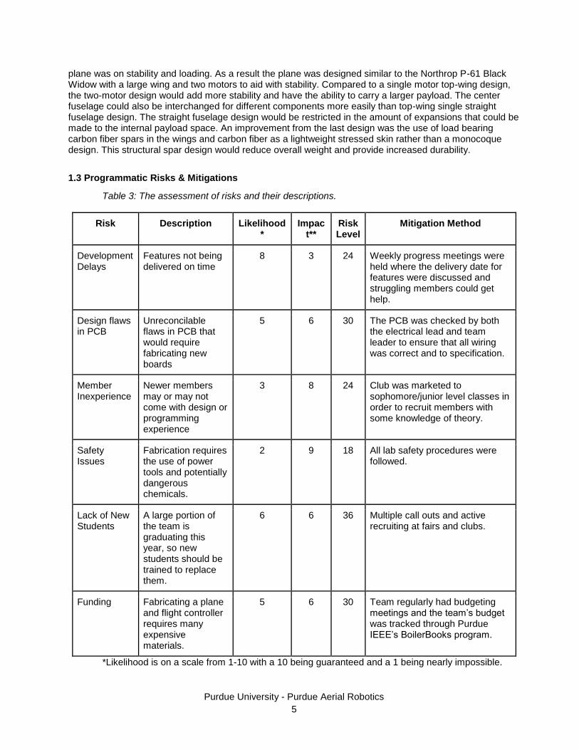
1.3 Programmatic Risks & Mitigations
Table 3: The assessment of risks and their descriptions.
Risk Description Likelihood*
Impact**
Risk Level
Mitigation Method
Development Delays
Features not being delivered on time
8 3 24 Weekly progress meetings were held where the delivery date for features were discussed and struggling members could get help.
Design flaws in PCB
Unreconcilable flaws in PCB that would require fabricating new boards
5 6 30 The PCB was checked by both the electrical lead and team leader to ensure that all wiring was correct and to specification.
Member Inexperience
Newer members may or may not come with design or programming experience
3 8 24 Club was marketed to sophomore/junior level classes in order to recruit members with some knowledge of theory.
Safety Issues
Fabrication requires the use of power tools and potentially dangerous chemicals.
2 9 18 All lab safety procedures were followed.
Lack of New Students
A large portion of the team is graduating this year, so new students should be trained to replace them.
6 6 36 Multiple call outs and active recruiting at fairs and clubs.
Funding Fabricating a plane and flight controller requires many expensive materials.
5 6 30 Team regularly had budgeting meetings and the team’s budget was tracked through Purdue IEEE’s BoilerBooks program.
*Likelihood is on a scale from 1-10 with a 10 being guaranteed and a 1 being nearly impossible.

Purdue University - Purdue Aerial Robotics
6
**Impact is on a scale from 1-10 with a 10 being catastrophic for a team and a 1 being a minor inconvenience.
2. System Design
2.1 Aircraft
The airframe model is based on the Northrop P-61 Black Widow and is composed of a main wing assembly, a tail assembly, two motor pods, and a central electronics pod. The main wing disassembles into three sections and are made with a skin of carbon fiber twill around a foam core with carbon fiber spar reinforcement. The tail is made of fiberglass skin with a foam core and 3D printed mounts. Ribs protruding from the wing act as mounts for the pods and landing gear. The wing acts as the main lift surface and structural component to house the pods and channel wiring to the servos, batteries, and tail. The front landing gear is made of stitch weave plates for strength and have two rubber wheels. The main wing joins together with telescoping spars and uses the motor pods as clamps to fix the wing sections in place.Carbon fiber tubes are clamped to the motor pods and run down to the tail assembly. These set of tubes act as the spars linking the tail to the main wing. The tail assembly consists of 3D printed brackets that clamp the two vertical stabilizers in place and fix the rear landing gear in place. The horizontal stabilizer has a carbon fiber spar that is clamped at both 3D printed brackets. The motor pods were fabricated with stitch weave carbon fiber layers formed into a rectangular shape. Each motor pod houses a motor, ESC, battery, and propeller. Fairings for the pods are made of a hollowed out foam shell that is latched to the main body of the pod. These fairings act as aerodynamic bodies to reduce drag behind the pods. The electronics pod is made from twill weave carbon fiber formed into a rectangular shape similar to the motor pods. The electronics pod has carbon fiber bulkheads and a second deck to hold the electronics in place and maintain the rigidity of the pod during flight. Antennas, flight controller boards, sensor boards, cameras, and other essential electronics are housed in the central electronics pod. Structural components such as the wing spar and landing gears were designed with a factor of safety of 2 using a 3g loading scenario. Other difficult to model components such as the carbon fiber ribs were designed with experimentally determined factors and loadings. Figure 1 shows the location of the main components and features.
Figure 1. The location of the main components and features of the Purdue Aerial Robotics UAV.

Purdue University - Purdue Aerial Robotics
7
2.1.1 Wing
To begin the design process, the total aircraft weight was estimated to be 10 kg. This value was based on the weight of the previous year’s aircraft (which had a similar configuration), changes in payload weight, and expected weight savings from improvements in construction. Using this weight along with the stall speed requirement and the characteristics of the selected airfoils (airfoils MH114 and MH115, chosen for their high lift-to-drag ratios and gentle stalls) produced an estimated main wing area of approximately 0.7 m2. A wingspan of 3 meters was chosen in order to maximize aspect ratio while remaining within structural and practical constraints. XFLR5 analysis was then used to refine the design. The airfoil shape in the central third of the wing was kept constant since that portion of the wing acted as a main structural element in the chosen configuration. However, taper and washout were still added to the outer thirds of the wing to approximate an elliptical lift distribution. Using constant-lift analysis, a cruise speed of 19 m/s was found to maximize the lift-to-drag ratio of the wing. The cruise lift-to-drag ratio given by XFLR5 VLM was 22, but the inclusion of loosely approximated fuselage drag lowered that value to 14. The horizontal and vertical tails were sized using tail volume coefficients. The values for these coefficients were selected based on the performance and handling of the previous year’s aircraft. The tail was then included in the XFLR5 analysis to obtain an incidence angle for the horizontal tail and to verify that static stability had been achieved. A simple dynamic stability analysis was also conducted to ensure that the aircraft was safe to fly.
Table 4. Airframe properties.
Performance
Aircraft Mass 10 kg
Cruise Speed 19 m/s (36.9 knots)
Stall Speed 12.22 m/s (23.8 knots)
Cruise Lift-to-Drag Ratio 14 (estimated)
Table 5. Wing and tail airfoil properties.
Main Wing Horizontal Tail Vertical Tail
Area 0.715 m2 0.11 m2 2 x 0.046 m2
Span 3 m 0.75 m 0.25 m
MAC 0.24 m 0.15 0.19
Aspect Ratio 12.59 5.11 1.36
Airfoil MH114 (root) MH115 (tip)
NACA 0009 NACA 0009
Loading 14 kg/ m2 - -
Taper Ratio 0.75 0 0.68
Incidence Angle 1 deg. -2 deg 0 deg
Washout 4 deg. - -

Purdue University - Purdue Aerial Robotics
8
Figure 2. Diagram of main wing (above) and horizontal tail (below).
Figure 3. Local lift curve along the length of the main wing.
2.1.2 Propulsion
The motors are Dualsky Xmotor EA series brushless outrunners coupled with 15x8E APC propellers, powered by Multistar 4S 14.8V 16000mAh lithium-polymer batteries and Turnigy brushless 80 amp ESCs. The total required power output for cruise is 130W. This system is capable of providing 1510W.
2.2 Autopilot
The autopilot system is built on a custom printed circuit board. It uses an STM32F4 microcontroller to run the main custom control stack, as well as an STM32F1, which is used as a co-processor. The requirements for autonomous flight as described in the rules drove choices on design for the board. The flight controller uses a 9-axis IMU, LIDAR rangefinder, GPS, barometer, and an airspeed sensor to collect information about the environment. The sensors were chosen due to ubiquity (how difficult would it be to find a replacement), cost in both dollars and development time, and quality. Initially, a separate magnetometer, accelerometer, and gyroscope were planned to be used, however concerns about development time lead to the adoption of an IMU with built-in sensor fusion software. In addition, the original intent was to have one microcontroller board for sensor processing and a second for control for the sake of modularity,however development and time constraints lead to the merging of the two into a compact, single board. A system diagram is shown in Fig. 4.

Purdue University - Purdue Aerial Robotics
9
Figure 4. A system diagram of the autopilot ground control system.
2.2.1 Hardware Design
A custom printed circuit board was created to minimize the complexity of the wiring in the UAV. This allows for much greater freedom in implementing parallel interfaces such as those used by the main and coprocessor. Another advantage is the low financial cost of developing a board versus using a prefabricated controller like a Pixhawk or Paparazzi controller. The finalized board design as well as a system level block diagram of the board can be seen in Fig. 5:

Purdue University - Purdue Aerial Robotics
10
Figure 6. The finalized custom circuit board design, and a system level block diagram. There are two microcontrollers on the board: the main processor and the coprocessor. The main
processor contains the flight controller, avionics, and ground control communication. The coprocessor acts as a “smart multiplexer” that passes either the outputs of the flight controller or the safety override controls to the control surfaces and propellers. The decision to separate the multiplexing of the signals into a separate processor was made so that if for any reason the main processor were to freeze or reset itself the plane could still be recovered.
2.2.2 Co-Processor
The backup processor behaves similar to a multiple channel parallel multiplexer. It takes in an input from both the safety controller and flight controller. Based on the state of the plane as well as inputs from the safety controls, the co-processor passes a signal to the control surfaces. In normal operation, the flight controller signals are passed through to the control surfaces. However, if a switch is flipped on the safety pilot’s controller, then the plane switches to manual control. If the coprocessor stops receiving packets from the safety controller, then it will flip to autonomous control for four seconds before placing itself in a “recovery position” that puts the plane in a dive. The four second safety period is set because it is the length of time it takes for a TARANIS module to power cycle. This prevents the plane from performing an unexpected dive due to a power fluctuation or safety pilot error.
2.2.3 Flight Control System
The flight control system is built on a STM32F4 microcontroller and features a hand-built kernel written in C with support for task scheduling. A list and breakdown of the tasks on the primary controller can be seen below:
Table 6. The tasks on the primary controller.
Task Description
Telemetry Radio Sends and receives communications between GCS and the Flight Controller
Serial Debug Allows for debugging through the main controller’s serial port
User Button Checks if the user button has been pressed
Sensors Updates sensor information
Inter-Micro Communications Sends control signals to the coprocessor

Purdue University - Purdue Aerial Robotics
11
Flight PID Control surface algorithm
Navigation Calculates error values to feed into control algorithm
2.2.4 LIDAR
The LIDAR module used is a LIDAR Lite v3. This LIDAR module was chosen because of the team’s familiarity with the LIDAR from other projects as well as its mechanical reliability. An I2C interface is used to communicate between the main board and the LIDAR. The LIDAR module is placed in the fuselage and pointed down. This is used for finding the altitude of the plane during takeoff and landing, as GPS and barometer altitude data is too coarse for such purposes. The algorithm for determining the plane’s ground height is as follows:
𝐷𝑖𝑠𝑡 = 𝑅𝑒𝑎𝑑𝑖𝑛𝑔 × |𝑥|
√𝑥2 + 𝑦2 + 𝑧2
Where Dist is the adjusted distance, Reading is the reading from the LIDAR, and x,y, and z is the magnitude of the plane’s unit orientation vector in the x,y, and z axis. This allows for the algorithm to compensate for when the LIDAR is not pointed directly down, such as during a flare on landing or maneuvering flight.
2.2.5 GPS
The GPS used is a NEO-M8N. The controller communicates to the GPS via the UBX protocol over a serial interface. This protocol was chosen over NMEA because communication is more efficient. With NMEA strings, if a particular piece of data was needed a particular type of string would have to be requested and would slow down communications with irrelevant pieces of data. Historically, using this approach also lead to stability issues as NMEA does not specify the message length nor does it have constant length messages, making parsing more difficult to perform reliably. The GPS provides the plane’s current location as well as information about its height and ground speed that is fused with pressure and airspeed data.
2.2.5 Airspeed
The airspeed sensor utilizes an MS4525DO differential pressure sensing chip. This sensor has pixhawk support so it was chosen for use due to its ubiquity and cost. The airspeed sensor uses a differential measurement to find the indicated airspeed of the UAV. The sensor then sends this information to the main control via an I2C connection. This information is then sent through a series of transfer functions to correct for temperature.
2.2.6 IMU
The IMU is a Bosch BNO055. The microcontroller communicates to it through an I2C connection. This IMU has a magnetometer, gyroscope, and accelerometer, as well as an on-chip ARM microcontroller. The onboard microcontroller fuses the sensor data to obtain vehicle orientation, and sends it to the flight controller as a quaternion. This quaternion is then converted to an Euler angle for use in the control algorithm. The BNO055 was chosen because it is one of the cheaper IMU units to develop for. The primary concern, its 100 Hz update rate, is less of an issue with a fixed wing plane than it is with a quadcopter. This is because quadcopters require a control output to maintain an orientation, whereas with simple fixed wing planes the control outputs are mainly used to change orientation due to disturbances. Thus, for a given fixed wing design, the IMU does not need to update nearly as fast as a quadcopter of equivalent complexity would require to stay aloft and stable.
2.2.7 Navigation and Control
The horizontal navigation system utilizes a lookahead control along with linear parameterization of the plane’s path to send a roll error term to the control unit. The lookahead control system finds the heading that would direct the plane towards a point 5 meters ahead of the point on the line defined by the UAS’s cross-track-error. The roll error is then fed to the horizontal control algorithm, the Simulink representation of which is shown in Fig. 7.

Purdue University - Purdue Aerial Robotics
12
Figure 7. A simulink representation of the horizontal control algorithm.
Each of the PID blocks contain a proportional control. Due to the physical forces on the wings, most oscillations are naturally dampened. The saturation block for heading-to-roll prevents the aircraft from rolling more than 30 degrees in a turn. The max pitch clamp is set for 45 degrees to prevent the plane from stalling itself if given a waypoint that would require climbing at an extreme angle.
2.2.8 Simulations
The gains for this algorithm were determined by developing a control algorithm in Simulink and testing it using a UDP interface with X-Plane 9. The stock model plane aircraft was used for sanity checking new developments to ensure that they would result in a stable controller given tuned constants. This prevented the team from pursuing non-viable controller designs and significantly sped up development of new control algorithms as the UAS did not have to be prepared to test new experimental features.
2.2.9 Ground Control Station
The Ground Control Station (GCS) is a custom application developed by Purdue Aerial Robotics in tandem with the onboard Flight Control System software. The GCS provides mission planning and controls, system status display, flight control system tuning, and debugging features. It also serves to tie together the multiple systems flying onboard the aircraft. Imagery and target characteristics from the Imaging System are paired by the GCS with aircraft telemetry information from the Flight Control System. A typical GCS display can be seen in Figure 8 below.
Figure 8. The Ground Control Station display.

Purdue University - Purdue Aerial Robotics
13
2.3 Obstacle Avoidance
Obstacle avoidance is not yet implemented. However, the system has features to make sure that the UAV
stays on course and does not leave the mission area. It will not allow a waypoint to be set to an area
deemed to be off limits. The lookahead algorithm also prevents the plane from deviating from the line
defined by the previous and current waypoint. This method allows for the team to parameterize the plane’s
path through the air and ensures that it remains on a path expected regardless of crosswind.
2.4 Imaging System
The Raspberry Pi Camera Module version 2 is an 8 megapixel camera with a maximum resolution of 3280 x 2464 pixels. Since the plane will be flying as low as possible while keeping within the vertical boundaries specified by the rules, the average altitude of the plane will be approximately 125 ft above the ground. At this height the camera resolution will translate to 1.81 pixels per inch. Thus, given a minimum of 1 inch thick lettering, the camera provides enough clarity for the autonomous object detection system to recognize the smallest objects it is required to identify. With an average airspeed of 13 meters per second, the camera needs to take an image at least once every 2.6 seconds. The Raspberry Pi Camera Module satisfies this condition, having the ability to take full resolution pictures at 15 frames per second. In addition to fulfilling the system’s image processing needs, this camera interfaces well with the raspberry pi which houses the object detection, classification and localization processes, reducing potential issues with compatibility.
2.5 Object Detection, Classification, Localization
The UAS detects, classifies, and localizes objects through seven major processes. The system detects regions of interest (objects) on the ground, separates the objects into a shape and a character, categorizes the color of the shape and character, identifies the shape, finds the character orientation, identifies the character, and synthesizes a final output. The OpenCV library is used throughout the project for its wide range of highly optimized image processing algorithms. 2.5.1 Region of Interest Detection In order to start processing a full-sized image, the unnecessary parts of the image must be filtered out. The remaining regions can then be further processed. Since the shapes and characters that must be identified in the competition all consist of relatively uniform colors relative to the background, a few simple filters can quickly reveal the regions of interest. The first part of this process is to convert the image from a BGR (Blue, Green, Red) color model to an HLS (Hue, Luminosity, Saturation) color model. The saturation channel of this image will now clearly indicate the color saturation of the image. This channel is then split into two bitwise images, a high-pass image and a low-pass image. The high-pass image is white where the saturation channel was above the mean saturation of the image. Conversely, the low-pass image is white where the saturation channel was below the mean saturation. This splitting allows for the detection of color uniformity for both high saturation and low saturation regions of interest. At this point, small dots are removed from both bitwise images through blurring and thresholding the bitwise images. This reduces noise in the images and allows more focus on the larger regions of interest. If either of the two bitwise images now contain over 75% white pixels, then that image undergoes a bitwise-not operation to shift the focus from the background to the regions of interest. Finally holes, black areas in the images completely surrounded by white, are filled, and the high-pass and low-pass bitwise images are combined. At this point, all regions of the original image with similar saturations are white in the combined bitwise image. Contours, the outlines of individual regions of interest, are found using the OpenCV contour finder on the black-and-white bitwise image. Contours with a very small area and contours that are very long are not processed further in order to reduce computation time. The remaining regions of interest are cropped out

Purdue University - Purdue Aerial Robotics
14
from the original image, masked by the bitwise ROI image and stored, along with its location in the image, to be further processed through object separation. 2.5.2 Object Separation This process uses the region of interest image, which only contains the potential shape and character surrounded in black, for the cases where the shape does not fill the rectangular-cropped image. It then outputs two bitwise images: an image which is white only where the character is, and another image which is white anywhere the shape (including the character) is. Firstly, the K-Means Color Clustering algorithm is used on the input image. The number of colors specified is 3, accounting for the shape color, character color, and black background. The K-Means algorithm produces one bitwise image for each color and its corresponding RGB color. The bitwise image for the shape is the image with the most white pixels other than the background color bitwise image. The bitwise image for the character is the remaining bitwise image which is neither the background nor the shape. Both the shape and character RGB colors are stored as well as the bitwise shape and character images. 2.5.3 Color Categorization This section takes the RGB colors from the object separation algorithm and categorizes them into a color name. The RGB color is first converted to the HLS color model. The color is categorized as black if the luminosity (L) is less than 20%, otherwise it is categorized as white if the luminosity is greater than 80%. If neither of those two conditions are the case, then if the saturation is less than 20% the color is categorized as gray. If the color is not in grayscale, then the hue is analyzed. A hue between 340° and 360° or between 0° and 10° is classified as red. A hue between 10° and 40° is classified as orange if the luminosity is greater than 40% or brown if the luminosity is less than 40%. A hue between 40° and 75° is classified as yellow, and a hue between 75° and 150° is classified as green. A hue between 150° and 240° is classified as blue. Between a hue of 240° and 260°, if the difference between the luminosity and 40% divided by the difference between the hue and 260° is greater than 1, then the color is classified as purple. Otherwise the color is classified as blue. Finally, a hue between 260° and 340° is classified as purple. 2.5.4 Shape Identification This process starts with the bitwise shape image from the object separation algorithm and outputs the name of the shape. First, the OpenCV contour finder is finds the contour of the shape. The curvature of the shape is determined by comparing the hough circle of the shape to the shape’s minimum enclosing circle. If the hough circle is larger than approximately 70% of the minimum enclosing circle, this is a good indicator that the shape is circular in nature. In this case, the hough circle’s area is calculated and the ratio of the hough circle area to the area of the contour determines whether the shape is a circle, semicircle, or quarter circle. If the shape is not circular, then an approximate polygon is fitted to the contour. The shape is then fitted with a minimum area rotated rectangle. If the area of this rectangle is approximately equal to the area of the contour, then the shape is rectangular in nature. The side lengths of the approximate polygon are then used to determine whether the shape is a square or a rectangle. If the shape is neither circular nor rectangular, then its shape classification can be determined solely by counting the number of sides, given the possible shapes specified in the rules. Four sides indicates a trapezoid, five sides indicates a pentagon, six sides indicates a hexagon, seven sides indicates a heptagon, eight sides indicates an octagon, ten sides indicates a star, and twelve sides indicates a cross. 2.5.5 Orientation Detection Detecting the character orientation from the bitwise character image, created in the object separation algorithm, relies heavily on the OpenCV implementation of Principal Component Analysis. Principal Component Analysis takes a set of points, in this case the white points on the bitwise character image, and uses what is essentially linear regression to find a line of best fit. This line is represented as a vector which points in the direction of the larger character dimension. For example, in the lowercase ‘l’ character, the larger character dimension is vertical whereas for the ‘w’ character the larger character dimension is horizontal. The reported angle of character relative to the image is determined by the larger vector

Purdue University - Purdue Aerial Robotics
15
dimension along with characteristics of the characters to account for the differences in larger vector dimension and true upward direction. 2.5.6 Character Identification The character identification process relies heavily on machine learning, more specifically the k-Nearest Neighbors (kNN) algorithm. The character classifier is trained on many fonts so that it can recognize most characters, including those which are hand painted or drawn. The training data and testing data are prepared in the same way to ensure optimal classification accuracy. First, the character bitwise image is rotated so that its orientation vector is vertical. Then the OpenCV contour finder is used to find the contour of the character, and just the outline of the character is drawn onto a new bitwise image. That image is then resized to a 100 by 100 pixel image for uniformity across samples. Finally, the newly resized image is fed into the character classifier and, using the kNN algorithm, the closest character name to the inputted bitwise image according to the training data is returned. 2.5.7 Synthesis Now that all of the necessary information has been gathered, a uniform final output must be synthesized. In this step, the object’s information is sent to the ground control station. There the local orientation and location of the object on the captured image are combined with the UAV position and orientation. Additionally, this final step waits for multiple reinforcing observations of the same object before sending its information to the judging station in order to ensure object detection accuracy.
2.6 Communications
The UAS has two main communications subsystems: the ground control interface and imaging interface. The interfaces are separated to minimize the risk of losing telemetry from the UAV. The imaging interface uses a Ubiquiti Bullet HP M5 transceiver on the UAV, and a Ubiquiti Nanostation M5 on the ground. These transceivers operate using Wi-Fi and transmit imagery to be processed on the ground. The Ground Control Interface uses two RFD900+ transceivers to communicate between the ground control and UAV. The communication interface is MAVLINK. The MAVLINK protocol was chosen because it is a commonly used industry standard and allows for the GCS to interact with a Pixhawk with slight modification. This lends the system some modularity as the flight controller doesn’t necessarily have to be Purdue made. In addition, it cuts the cost in development time and safety of developing an entirely handmade protocol for communication. In addition, there is a manual control interface that is used when a safety pilot is needed. The RFD900+ transmitters use 900-928 GHz FHSS communication, and the imaging system uses 5.8 GHz Wi-Fi. The RC safety control uses 2.4 GHz FHSS communication. The UAS sends numerous different types of packets using the MAVLINK interface. A table of the different commands and their purposes are shown in Table 8.
Table 7. Commands sent using the MAVLINK interface
Packet Type Purpose
Ground Control to UAV Packet
INVALID_MSG Notifies the sender that a previously sent message was invalid.
NAV_SET_MODE Starts and stops the navigation system
NAV_WAYPOINTS_PUSH Sends a new waypoint to the plane
NAV_WAYPOINTS_CLEAR Clears all waypoints

Purdue University - Purdue Aerial Robotics
16
SET_PID_CONSTANTS Sets control constants for control surfaces
UAV to Ground Control Packet
HEARTBEAT Sends flight control state to GCS
TELEMETRY_ALL Contains telemetry
MAVRCV_NAV_WAYPOINTS_REQUEST Requests the next waypoint from the GCS
2.7 Cyber-Security
As encryption was not critical to the functioning of the autopilot, it was not worked on extensively. However, the custom nature of the communications software makes it very difficult to interfere with. The flight controller uses a custom MAVLink interface. In addition, the cyclical redundancy check (CRC) algorithm is not the same algorithm defined by MAVLink spec. This makes spoofing messages difficult, as the CRC has to be correct for a message to be parsed. The limited nature of the communications also hampers attackers. The only information that can be sent to the plane is adjustments for the PID system or adding and removing waypoints. If this were to occur, operators at the ground control station would likely take over with manual control. Since the manual control is based on signals received from the safety controller and not the flight controller, the plane cannot be abducted without also spoofing the RC control. The RC control is as vulnerable as other RC control systems, however since it is a frequency hopping spread spectrum interface, it is difficult to jam the controls or spoof messages without finding the frequency sequence used to control the manual flight algorithm.
3. Test and Evaluation Plan
3.1 Developmental Testing
The developmental testing plan for the UAV is designed to provide tasks of increasing complexity while minimizing risks to personnel or property. The first test conducted after a new flight board PCB is constructed are power on tests. These tests ensure that the processors on the board are properly soldered and are not defective. If the board does not power on, then a root-cause analysis is conducted and the problem is fixed. After a sensor driver is developed, the sensor output is sent to a debugging serial and sanity checked. If there is any quantitative method of measuring accuracy (e.g. rotating an IMU 90 degrees using a square), then that is performed as well. When the flight controller was completed, the flight algorithms were tested. First, the attitude hold was tested, then the pitch hold, then the navigation system, and then finally the vertical navigation. For each subsystem, the plane was tested on the ground without a propeller and held in various orientations to ensure that the plane was responding in an expected manner. Then, the plane was taken to an altitude where the safety pilot could recover from a dive and tested thoroughly. The data was also logged on the flight controller.
1. Ensure sensor operation and comms with GCS telemetry data 2. Ensure level flight/roll hold works 3. Ensure pitch hold works 4. Test waypoint navigation 5. Integrate vertical controller 6. Takeoff algorithm 7. Landing algorithm

Purdue University - Purdue Aerial Robotics
17
3.2 Individual Component Testing
3.2.1 Sensors
All of the I2C sensors were left operating during long periods of time while their output was checked against known reference values. This was to ensure both the stability and functionality of the drivers for the sensors. Special tests were performed for the IMU and GPS to ensure that the sensors were properly functioning. The IMU was checked using a square. The sensor was rotated 90 degrees and the resulting orientation was checked against a known angle. The orientation sensor had less than two degrees of inaccuracy in four 90 degree turns. The IMU was also left alone in the same orientation to check for any drift. There was no indication of a constant drift during operation. The IMU was also drop tested to see if sudden changes in movement would alter the orientation received. There was a slightly larger orientation drift due to this than in normal operation however after further testing it returned to being less than two degrees out of alignment. The GPS was checked outside using a google maps comparison. The location that the GPS reported was within 5 meters of the expected position.
3.2.2 Control Algorithm
The control algorithm was first simulated in X-Plane and run for 10 minutes to ensure stability. Then the algorithm was tested with different initial conditions to ensure that the system is robust. The algorithm is then translated into a C equivalent function and run with known inputs to ensure that the outputs for the Simulink and C version are similar. Finally, the algorithm is loaded into the flight controller and tested during a controlled test flight.
Figure 9. UAV roll over time.
As of writing, the roll hold algorithm has been checked however flooding has closed down the team’s flight field so waypoint based flight has not been tested in the air. Fig. 9 shows the roll hold test flight. There are short periods of maneuvering flight, but when the roll hold is enabled the plane stays relatively level. Fig 10 shows a MATLAB simulation of the lookahead algorithm with the blue lines as a closed path between four waypoints and the orange line representing the simulated plane. For the simulation, a UAS with a given heading and a speed of one graphical unit is placed on a grid with one fixed waypoint along the X-axis and two random other waypoints. At each step, the guidance algorithm calculates a new desired heading and the plane moves towards that heading at 10 degrees/step. This simulation demonstrates that the control algorithm is capable of following a path parametrically determined by two waypoints.

Purdue University - Purdue Aerial Robotics
18
Figure 10. MATLAB simulation of the lookahead algorithm. Blue lines show a closed path between four waypoints, and orange curve represents the simulated plane.
3.2.3 GCS-Plane Communication
The plane and GCS communication has been run through stability tests to ensure their proper operation. After running the GCS and the plane for over one hour during Purdue’s Computer Science Demo Day. The communication has also been range tested, and is able to maintain communications for every distance measured, the furthest of which was nearly 0.5 km.
3.2.4 Image Processing
Figure 11. Determining the shape, character, and color names from an example test image.
Above in Fig. 11 the image processing algorithms correctly identify the two shape objects with their correct
shape name, character name, and color names. The orange jacket on the ground, however, is classified as
an “Unknown Object” meaning that it is not a standard object.
Purdue University - Purdue Aerial Robotics
19
3.3 Mission Testing Plan
Purdue Aerial Robotics mission plan is focused on validating the custom autopilot in a competition setting while using the image processing system to find targets. The system is to be ran in conditions as close to those in the competition as possible given crew availability and flight conditions. The mission plan for every competition level test is decided on the basis of maximizing the quantity of tasks that can be completed on a given run so as to ascertain the team’s readiness to operate within various configurations and under a variety of circumstances. Mock-ups of targets have been made in order to test computer vision systems, and autopilot systems are to be tested under varying levels of autonomy ranging from waypoint navigation to target location. Before each flight, a preflight check will be conducted to verify that all systems are functioning normally. A flight plan document will be referred to for expected operations and remedies for wing control surfaces, power systems, and other electronics both on the plane and on the GCS. A pilot will be accompanied by a spotter with binoculars to verify the integrity of the airframe during flights. Other team members will be focused on operating the GCS and speaking out changes in status of component systems during flights. For any unexpected deviation from the mission plan, the team captain has the final say in whether manual takeover is warranted. The most senior member of the aero-mechanical and electrical team will provide guidance on whether a given malfunction requires emergency landing.
4. Safety, Risks, and Mitigation
4.1 Developmental Risks and Mitigations
The primary safety concern for electrical team was the risk of damage due to electrical shorts or a runaway plane. To mitigate this, a 3D printed case for the flight controller was made to prevent it from being exposed to the outside environment. The other major development risk is accidental arming of the plane during electrical adjustments. For this reason the motors are only powered directly before taxiing.
4.2 Mission Risks and Mitigations
Due to the one-time nature of the competition, malfunctions or mishaps may endanger the performance of the team. In addition, a failure to mitigate potential risks could endanger being approved after a flight readiness review. Thus, a number of potential risks have been assessed and mitigated.
4.2.1 Loss of Autonomous Control
A loss of autonomous control would entail the flight controller restarting mid-flight or communications ceasing during flight. To mitigate this, flight controller models are stability tested before they are taken into the air. Changes to control are tested on the ground by tilting the plane by hand before they are flown. Capacitors have been added to the power supply to reduce the risk of a brownout.
4.2.2 Loss of Manual Control
The plane does not respond to manual override or input. Coprocessor has been rigorously stability tested and capacitors have been added to the power supply to reduce the risk of a brownout. Failsafe systems will send the plane into a downwards spiral in case of extended loss of manual control.
4.2.3 Loss of Telemetry
Intermittent loss of telemetry due to power fluctuations or damage. The transceiver antennas are designed so that no matter the orientation of the plane the transmission pattern will remain strong.
4.2.4 Malfunctioning Control Surface/Motor
Control surface or motor does not respond or responds inappropriately to input. All control surfaces are checked prior to flight..

Purdue University - Purdue Aerial Robotics
20
4.3 Operational Risks and Mitigations
Due to the energy required to fly, there are numerous scenarios which could cause danger to crew or property. While preparing for every eventuality is difficult, there are some common scenarios that could cause a risk to Aerial Robotics’ property or members.
4.3.1 Uncontrolled Flight
One of the concerns that drove several design decisions was the undesirability of uncontrolled flight, defined as the UAS not responding to manual override or waypoint navigation. This was the primary reason a coprocessor was introduced to the board. The coprocessor has the final say in whether manual or autonomous flight is used. The code used on the coprocessor has been rigorously stability tested the override is checked before every flight. So long as the coprocessor runs, manual override is available. To ensure that the plane can always be taken over, a safety pilot is always ready during any test flight. In addition, the radio antennas for the safety control transmitter has a range of more than 5km to ensure that signal is not lost. In addition, the plane will put itself into a “recovery mode” if communications is lost for more than four seconds with the safety controller. The recovery position will stall the plane and keep it in a nosedive where communications was lost so that it doesn’t fly over any populated area or valuable equipment.
4.3.2 Flight Controller Lockup
Another region of concern is the flight controller freezing or losing communication mid-flight. If the controller stops responding, then the coprocessor allows for the safety pilot to take over, mitigating the risk of a crash. When the plane is given power, the autopilot is run and the expected control surface deflection is checked to ensure that the flight controller will respond to disturbances as expected. In addition, the telemetry packets are checked on the GCS to ensure that continuous communication is occurring between the GCS and UAV. If communication is broken between the GCS and UAV, then the reason is investigated before the plane is okayed for flight.
4.3.3 Brownout
Brownouts are a common issue for electrical systems containing motors. Because of the sensitivity of microcontrollers to drops in voltage, a brownout could cause loss of commands for the main flight controller. If this occurs, then the safety pilot will take over. To mitigate this, power electronics such as capacitors and a dedicated 5 volt regulator for the board have been added to the power system to handle an increased instantaneous power load.
4.3.4 Loss of Communications
A possibility that can occur during flight is the loss of communications between the safety pilot and the plane. To mitigate this, transmitters with a range of more than 1km have been used to ensure that communications will be solid. Communications are tested during setup to ensure that the UAV is sending and receiving information.