pump seals agitator seals compressor sels · mechanical seals magnetic couplings agitator seals...
TRANSCRIPT
Mechanical sealsMagnetic couplings
Agitator seals
Compressor sels
Pump seals
Magnetic couplings
11
Content and other brochures
Mechanical seals
Index . . . . . . . . . . . . . . . . . . . . . . . . . . . . . . . .5Mechanical seals for pumps . . . . . . . . . . . . . . . . . . . . 6Agitator seals . . . . . . . . . . . . . . . . . . . . . . . . . . . . . . . 96Compressor seals . . . . . . . . . . . . . . . . . . . . . . . . . . . .116
EagleBurgmann – Your System Supplier
Separately available brochures offer information about additional product lines as well as notes on the technology and selection of mechanical seals.
All products can be retrieved interactively from eagleburgmann.com. Among others, you will find current data sheets in PDF format available for download here.
Mechanical seal technology and selection
Brochure 58 pages (Code: DMS_TSE)
Technical principles, designation codes, API plans, notes on installation and operation and articles covering theory and practice are summarized in the first part.The second part concerns choosing a seal according to media. Recommendations for arrangement, operation, type and materials of the required mechanical seal for over 900 media.With extensive additional information.
Magnetic couplings
Index . . . . . . . . . . . . . . . . . . . . . . . . . . . . . .131Couplings . . . . . . . . . . . . . . . . . . . . . . . . . . . . . . . 132Bearings . . . . . . . . . . . . . . . . . . . . . . . . . . . . . . . . 137
Seal supply systems
Brochure 84 Pages (Code: DMS_SSE)
The entire product portfolio of systems and components for the cooling, flushing, pressurization and supplying of liquid and gas-lubricated mechanical seals, e.g. quench and Thermosiphon systems, heat exchangers, buffer pressure systems, leakage monitoring and API682-compliant supply systems.
Carbon floating ring seals
Brochure 32 Pages (Code: EBES)
Maintenance-free, compact cartridge labyrinth seals with long service life and best performance from EagleBurgmann-Espey. For the sealing of gases, dust and vapors in turbines, fans, compressors, centrifuges and mills.
Additional Information
Materials table . . . . . . . . . . . Inside back cover
TotalSealCare . . . . . . . . . . . . . . . . . . Outside back coverCompany profile . . . . . . . . . . . . . . . . . . . . . . . . . . . . . . 2Additional product lines . . . . . . . . . . . . . . . . . . . . . . . 138
Important note
All the technical specifi cations are based on extensive tests and our many years of experience. However, the diversity of possible applications means that they can serve as guide values only.
It should be noted that the extremal values of each operating parameter cannot be applied at the same time because of their interaction. Furthermore, the operating range of each specifi c product depends on the respective shaft diameter, materials used, mode of operation and on the medium to be sealed.
A guarantee can only be given in the individual case if the exact conditions of application are known and these are confi rmed in a special agreement. When critical conditions of operation are involved, we recommend consulting with our specialist engineers.
Subject to change.
22

33
EagleBurgmann products deliver safe, reliable sealing performance in any application including oil pumping and cracking, gas compression, process gas containment, phase separation or synthesis of chemical substances, pipeline sealing, dairy product fi lling or compensation of temperature expansion in fl ue gas systems.
Our challenge is to design seals that are able to withstand a wide range of media, diff erent aggregate states and varying pressure and temperature and to provide special solutions for small installation up to seal contact areas of several meters. Every application has its own special requirements profi le, and our job is to provide the best sealing solution.
The EagleBurgmann portfolio: A product range with an unlimited horizon.EagleBurgmann is one of the world’s leading manufacturer of industrial sealing solutions. Our extensive portfolio includes everything from standard seals to one-off application-specifi c designs:
• Mechanical seals• Magnetic couplings• Seal supply systems• Carbon floating ring seals• Compression packings• Gaskets• Expansion joints• Special products• TotalSealCare Services
Total commitment to quality excellence.Outstanding quality is the top priority at EagleBurgmann. Our products are designed for user-friendly installation, optimal functionality and long service life. Our R&D activities, advanced quality management system, in-house test facilities and in-depth engineering expertise ensure that our seals meet the most demanding customer expectations. Starting right back in the development phase, our employees continually verify the quality of our products, and we carry out systematic inspection and testing to guarantee that customers are getting top quality.
Proud of the trust which our customers place in us.EagleBurgmann is a dependable, competent partner. Our customers are always in total control of the media in their pumps, agitators, compressors, blowers, turbines, valves and pipeline systems even when operating conditions are extremely harsh. There is good reason why customers in the oil & gas, refi nery, chemical, energy, food processing, paper, water, marine, aerospace, mining and other industries choose EagleBurgmann as their sealing solutions supplier.
Our products –as varied as our customers
44
55
Split sealsSplitex . . . . . . . . . . . . . . . . . . . . . . . . . . . . . . . . . . . 84HGH201 . . . . . . . . . . . . . . . . . . . . . . . . . . . . . . . . . . 86
Gas-lubricated sealsCartex-GSDN . . . . . . . . . . . . . . . . . . . . . . . . . . . . . . 88EM300 . . . . . . . . . . . . . . . . . . . . . . . . . . . . . . . . . . . 89CGSH-K . . . . . . . . . . . . . . . . . . . . . . . . . . . . . . . . . . 90GSO-DN . . . . . . . . . . . . . . . . . . . . . . . . . . . . . . . . . . 92HRGS-D . . . . . . . . . . . . . . . . . . . . . . . . . . . . . . . . . . 93NF992 . . . . . . . . . . . . . . . . . . . . . . . . . . . . . . . . . . . 94
Agitator seals
Dry-running sealsSeccoMix . . . . . . . . . . . . . . . . . . . . . . . . . . . . . . . . . 96AD510/AD520 . . . . . . . . . . . . . . . . . . . . . . . . . . . . . 98
Gas-lubricated sealsAGSZ . . . . . . . . . . . . . . . . . . . . . . . . . . . . . . . . . . . 100AGSR . . . . . . . . . . . . . . . . . . . . . . . . . . . . . . . . . . . 102
Liquid-lubricated sealsERB/ERC . . . . . . . . . . . . . . . . . . . . . . . . . . . . . . . . 104M481 . . . . . . . . . . . . . . . . . . . . . . . . . . . . . . . . . . . 106M461 . . . . . . . . . . . . . . . . . . . . . . . . . . . . . . . . . . . 108MR-D . . . . . . . . . . . . . . . . . . . . . . . . . . . . . . . . . . . 110HS-D . . . . . . . . . . . . . . . . . . . . . . . . . . . . . . . . . . . 112HSH-D . . . . . . . . . . . . . . . . . . . . . . . . . . . . . . . . . . 113HSHLU-D . . . . . . . . . . . . . . . . . . . . . . . . . . . . . . . . 114
Shut-down sealSTD1 . . . . . . . . . . . . . . . . . . . . . . . . . . . . . . . . . . . 115
Compressor seals
Gas-lubricated sealsDGS . . . . . . . . . . . . . . . . . . . . . . . . . . . . . . . . . . . . 116PDGS . . . . . . . . . . . . . . . . . . . . . . . . . . . . . . . . . . . 118MDGS. . . . . . . . . . . . . . . . . . . . . . . . . . . . . . . . . . . 120TDGS . . . . . . . . . . . . . . . . . . . . . . . . . . . . . . . . . . . 122NF941 . . . . . . . . . . . . . . . . . . . . . . . . . . . . . . . . . . 123WRS . . . . . . . . . . . . . . . . . . . . . . . . . . . . . . . . . . . . 124EBU800 . . . . . . . . . . . . . . . . . . . . . . . . . . . . . . . . . 125
Separation sealsCSE . . . . . . . . . . . . . . . . . . . . . . . . . . . . . . . . . . . . 126CSR . . . . . . . . . . . . . . . . . . . . . . . . . . . . . . . . . . . . 127CobaSeal . . . . . . . . . . . . . . . . . . . . . . . . . . . . . . . . 128
Mechanical seals for pumps
Pusher sealsM2N . . . . . . . . . . . . . . . . . . . . . . . . . . . . . . . . . . . . . . 6M3N . . . . . . . . . . . . . . . . . . . . . . . . . . . . . . . . . . . . . . 8 M7N . . . . . . . . . . . . . . . . . . . . . . . . . . . . . . . . . . . . . 10M74-D . . . . . . . . . . . . . . . . . . . . . . . . . . . . . . . . . . . 12H7N . . . . . . . . . . . . . . . . . . . . . . . . . . . . . . . . . . . . . 14HA211 . . . . . . . . . . . . . . . . . . . . . . . . . . . . . . . . . . . 16LB500 . . . . . . . . . . . . . . . . . . . . . . . . . . . . . . . . . . . 17H74-D . . . . . . . . . . . . . . . . . . . . . . . . . . . . . . . . . . . . 18EK700 . . . . . . . . . . . . . . . . . . . . . . . . . . . . . . . . . . . 20Pulace . . . . . . . . . . . . . . . . . . . . . . . . . . . . . . . . . . . 21HRN . . . . . . . . . . . . . . . . . . . . . . . . . . . . . . . . . . . . . 22H75VN . . . . . . . . . . . . . . . . . . . . . . . . . . . . . . . . . . . 24H75VK . . . . . . . . . . . . . . . . . . . . . . . . . . . . . . . . . . . 26HJ92N . . . . . . . . . . . . . . . . . . . . . . . . . . . . . . . . . . . 28H12N . . . . . . . . . . . . . . . . . . . . . . . . . . . . . . . . . . . . 30H3B . . . . . . . . . . . . . . . . . . . . . . . . . . . . . . . . . . . . . 32H10/H8 . . . . . . . . . . . . . . . . . . . . . . . . . . . . . . . . . . 33
Standard cartridge sealsCartex Single seals . . . . . . . . . . . . . . . . . . . . . . . . . 34Cartex Dual seals . . . . . . . . . . . . . . . . . . . . . . . . . . 36Cartex ANSI Single seals . . . . . . . . . . . . . . . . . . . . . 38Cartex ANSI Dual seals . . . . . . . . . . . . . . . . . . . . . . 40MA290/MA390 . . . . . . . . . . . . . . . . . . . . . . . . . . . . 42Unitex . . . . . . . . . . . . . . . . . . . . . . . . . . . . . . . . . . . . 44Mtex Single seals . . . . . . . . . . . . . . . . . . . . . . . . . . . 46Mtex Dual seals . . . . . . . . . . . . . . . . . . . . . . . . . . . . 48APItex . . . . . . . . . . . . . . . . . . . . . . . . . . . . . . . . . . . 50
Elastomer bellows sealsMG1 . . . . . . . . . . . . . . . . . . . . . . . . . . . . . . . . . . . . . 52MG9 . . . . . . . . . . . . . . . . . . . . . . . . . . . . . . . . . . . . . 54EA560 . . . . . . . . . . . . . . . . . . . . . . . . . . . . . . . . . . . 56ED560 . . . . . . . . . . . . . . . . . . . . . . . . . . . . . . . . . . . 57EA100 . . . . . . . . . . . . . . . . . . . . . . . . . . . . . . . . . . . 58EH700 . . . . . . . . . . . . . . . . . . . . . . . . . . . . . . . . . . . 59BT-AR . . . . . . . . . . . . . . . . . . . . . . . . . . . . . . . . . . . . 60BT-A2 . . . . . . . . . . . . . . . . . . . . . . . . . . . . . . . . . . . . 62BT-PN . . . . . . . . . . . . . . . . . . . . . . . . . . . . . . . . . . . . 63
Metal bellows sealsMBS100 . . . . . . . . . . . . . . . . . . . . . . . . . . . . . . . . . . 64MFL85N . . . . . . . . . . . . . . . . . . . . . . . . . . . . . . . . . . 66MFLWT . . . . . . . . . . . . . . . . . . . . . . . . . . . . . . . . . . 68MFLCT . . . . . . . . . . . . . . . . . . . . . . . . . . . . . . . . . . . 69MF95N . . . . . . . . . . . . . . . . . . . . . . . . . . . . . . . . . . . 70YE400 . . . . . . . . . . . . . . . . . . . . . . . . . . . . . . . . . . . 71MFL65 . . . . . . . . . . . . . . . . . . . . . . . . . . . . . . . . . . . 72
Engineered sealsEK777 . . . . . . . . . . . . . . . . . . . . . . . . . . . . . . . . . . . 73HR . . . . . . . . . . . . . . . . . . . . . . . . . . . . . . . . . . . . . . 74HRC...N . . . . . . . . . . . . . . . . . . . . . . . . . . . . . . . . . . . 76SH(V) . . . . . . . . . . . . . . . . . . . . . . . . . . . . . . . . . . . . 78SHF/SHP . . . . . . . . . . . . . . . . . . . . . . . . . . . . . . . . . 79SHPV/SHFV . . . . . . . . . . . . . . . . . . . . . . . . . . . . . . . 80SAF(V)/SAP(V) . . . . . . . . . . . . . . . . . . . . . . . . . . . . 81SHF(V)-D/SHP(V)-D . . . . . . . . . . . . . . . . . . . . . . . . 82
Mechanical seals for pumpsEagleBurgmann off ers a complete range of liquid and gaslubricated pump shaft seals including standard and engineered seals in single and multi-seal versions. We also off er a complete range of solutions for all API 682 4th edition* categories and arrangements. The portfolio includes a broad selection of material and surface technologies such as DiamondFaces coatings.
Mechanical seals for agitatorsSealing solutions for normal and sterile applications. The design and selection of materials ensure that the seals are rugged enough to deliver outstanding cost and engineering performance in everyday applications.
Mechanical seals for compressorsA complete range of products for process gas compressors from a single source. Single, double and tandem versions and tandem seals with intermedia labyrinths. Rugged, non-wearing, non-contact seals designed to deliver outstanding performance and long service life.
* Request our separately available API 682 printed publication series. Additional comprehensive documents and information are available at eagleburgmann.com/api682.
Mechanical seals 1
6
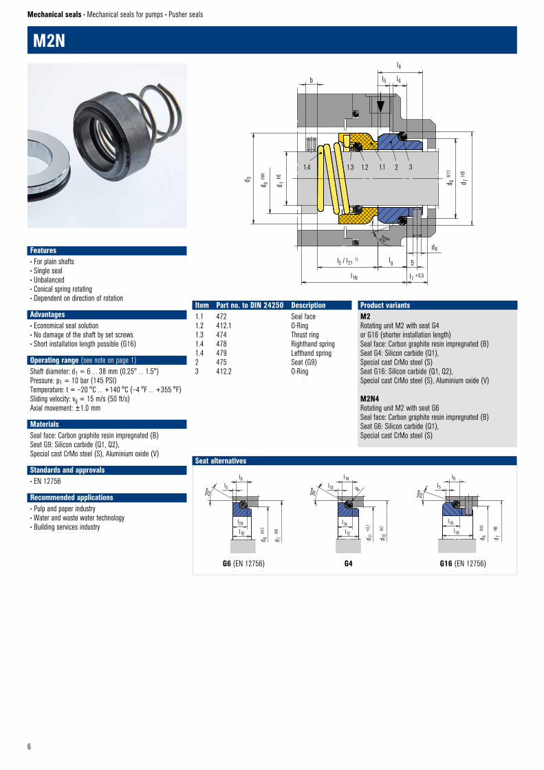
M2N
Mechanical seals • Mechanical seals for pumps • Pusher seals
Features• For plain shafts• Single seal• Unbalanced• Conical spring rotating• Dependent on direction of rotation
Advantages• Economical seal solution• No damage of the shaft by set screws• Short installation length possible (G16)
Operating range (see note on page 1)Shaft diameter: d1 = 6 … 38 mm (0.25" … 1.5")Pressure: p1 = 10 bar (145 PSI)Temperature: t = –20 °C … +140 °C (–4 °F … +355 °F)Sliding velocity: vg = 15 m/s (50 ft/s)Axial movement: ±1.0 mm
MaterialsSeal face: Carbon graphite resin impregnated (B)Seat G9: Silicon carbide (Q1, Q2), Special cast CrMo steel (S), Aluminium oxide (V)
Standards and approvals• EN 12756
Recommended applications• Pulp and paper industry• Water and waste water technology• Building services industry
Item Part no. to DIN 24250 Description1.1 472 Seal face1.2 412.1 O-Ring1.3 474 Thrust ring1.4 478 Righthand spring1.4 479 Lefthand spring2 475 Seat (G9)3 412.2 O-Ring
M2 Rotating unit M2 with seat G4 or G16 (shorter installation length)Seal face: Carbon graphite resin impregnated (B)Seat G4: Silicon carbide (Q1), Special cast CrMo steel (S)Seat G16: Silicon carbide (Q1, Q2), Special cast CrMo steel (S), Aluminium oxide (V)
M2N4 Rotating unit M2 with seat G6Seal face: Carbon graphite resin impregnated (B)Seat G6: Silicon carbide (Q1), Special cast CrMo steel (S)
Product variants
1.4 1.3 1.2 1.1 2 3
d 3
d b m
in
d 1 h
6
b
l8
l5 l6
d 6 H
11
d 7 H
8
d8
l9 5l3 / l21 1)
l1N
20°
EagleBurgmann © M2N
l7 +0,5
G6 (EN 12756) G4 G16 (EN 12756)
Seat alternatives
l28
l10
d7
H8
d6
H11
l6 l5
20°
G6 (M32N4) © EagleBurgmann
30°
l16l15 R
G4 © EagleBurgmann
l12
l14
d 11
+0,1
d 12
H7
d 7
H8
d 6
H11
l6l5
20°
l19
l18
G16 © EagleBurgmann
7
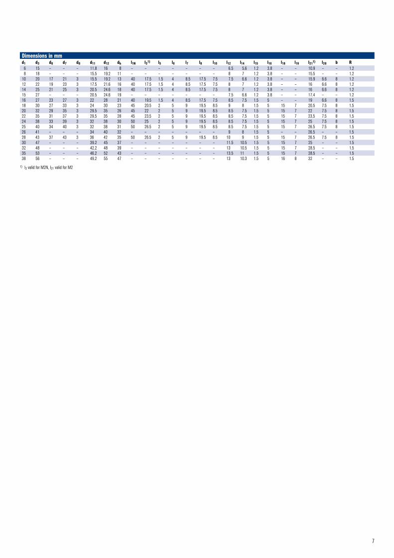
Dimensions in mmd1 d3 d6 d7 d8 d11 d12 db l1N l31) l5 l6 l7 l8 l10 l12 l14 l15 l16 l18 l19 l211) l28 b R 6 15 – – – 11.8 16 8 – – – – – – – 6.5 5.6 1.2 3.8 – – 10.9 – – 1.28 18 – – – 15.5 19.2 11 – – – – – – – 8 7 1.2 3.8 – – 15.5 – – 1.2
10 20 17 21 3 15.5 19.2 13 40 17.5 1.5 4 8.5 17.5 7.5 7.5 6.6 1.2 3.8 – – 15.9 6.6 8 1.212 22 19 23 3 17.5 21.6 16 40 17.5 1.5 4 8.5 17.5 7.5 8 7 1.2 3.8 – – 16 6.6 8 1.214 25 21 25 3 20.5 24.6 18 40 17.5 1.5 4 8.5 17.5 7.5 8 7 1.2 3.8 – – 16 6.6 8 1.215 27 – – – 20.5 24.6 19 – – – – – – – 7.5 6.6 1.2 3.8 – – 17.4 – – 1.216 27 23 27 3 22 28 21 40 19.5 1.5 4 8.5 17.5 7.5 8.5 7.5 1.5 5 – – 19 6.6 8 1.518 30 27 33 3 24 30 23 45 20.5 2 5 9 19.5 8.5 9 8 1.5 5 15 7 20.5 7.5 8 1.520 32 29 35 3 29.5 35 26 45 22 2 5 9 19.5 8.5 8.5 7.5 1.5 5 15 7 22 7.5 8 1.522 35 31 37 3 29.5 35 28 45 23.5 2 5 9 19.5 8.5 8.5 7.5 1.5 5 15 7 23.5 7.5 8 1.524 38 33 39 3 32 38 30 50 25 2 5 9 19.5 8.5 8.5 7.5 1.5 5 15 7 25 7.5 8 1.525 40 34 40 3 32 38 31 50 26.5 2 5 9 19.5 8.5 8.5 7.5 1.5 5 15 7 26.5 7.5 8 1.526 41 – – – 34 40 32 – – – – – – – 9 8 1.5 5 – – 26.5 – – 1.528 43 37 43 3 36 42 35 50 26.5 2 5 9 19.5 8.5 10 9 1.5 5 15 7 26.5 7.5 8 1.530 47 – – – 39.2 45 37 – – – – – – – 11.5 10.5 1.5 5 15 7 25 – – 1.532 48 – – – 42.2 48 39 – – – – – – – 13 10.5 1.5 5 15 7 28.5 – – 1.535 53 – – – 46.2 52 43 – – – – – – – 13.5 11 1.5 5 15 7 28.5 – – 1.538 56 – – – 49.2 55 47 – – – – – – – 13 10.3 1.5 5 16 8 32 – – 1.5
1) l3 valid for M2N, l21 valid for M2
8
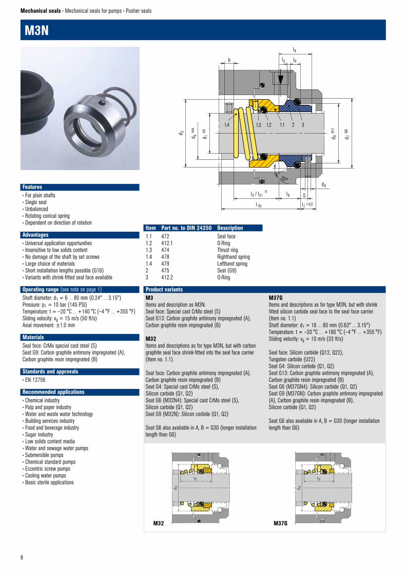
M3N
Mechanical seals • Mechanical seals for pumps • Pusher seals
Item Part no. to DIN 24250 Description1.1 472 Seal face1.2 412.1 O-Ring1.3 474 Thrust ring1.4 478 Righthand spring1.4 479 Lefthand spring2 475 Seat (G9)3 412.2 O-Ring
Features• For plain shafts• Single seal• Unbalanced• Rotating conical spring• Dependent on direction of rotation
Advantages• Universal application opportunities• Insensitive to low solids content• No damage of the shaft by set screws• Large choice of materials• Short installation lengths possible (G16)• Variants with shrink-fitted seal face available
Operating range (see note on page 1)Shaft diameter: d1 = 6 … 80 mm (0.24" … 3.15")Pressure: p1 = 10 bar (145 PSI)Temperature: t = –20 °C … +140 °C (–4 °F … +355 °F)Sliding velocity: vg = 15 m/s (50 ft/s)Axial movement: ±1.0 mm
MaterialsSeal face: CrMo special cast steel (S)Seat G9: Carbon graphite antimony impregnated (A),Carbon graphite resin impregnated (B)
Standards and approvals• EN 12756
Recommended applications• Chemical industry• Pulp and paper industry• Water and waste water technology• Building services industry• Food and beverage industry• Sugar industry• Low solids content media• Water and sewage water pumps• Submersible pumps• Chemical standard pumps• Eccentric screw pumps• Cooling water pumps• Basic sterile applications
1.4 1.3 1.2 1.1 2 3
l8
l5 l6b
d 3
d b m
in
d 1 h6
20°
l3 / l21 3)
l9 5
d8
l1N
EagleBurgmann © M3N
d 6 H1
1
d 7 H8
l7 +0,5
M3Items and description as M3N.Seal face: Special cast CrMo steel (S)Seat G13: Carbon graphite antimony impregnated (A), Carbon graphite resin impregnated (B)
M32Items and descriptions as for type M3N, but with carbon graphite seal face shrink-fitted into the seal face carrier (Item no. 1.1).
Seal face: Carbon graphite antimony impregnated (A), Carbon graphite resin impregnated (B) Seat G4: Special cast CrMo steel (S), Silicon carbide (Q1, Q2)Seat G6 (M32N4): Special cast CrMo steel (S), Silicon carbide (Q1, Q2)Seat G9 (M32N): Silicon carbide (Q1, Q2)
Seat G6 also available in A, B = G30 (longer installation length than G6)
M37GItems and descriptions as for type M3N, but with shrink fitted silicon carbide seal face to the seal face carrier (Item no. 1.1)Shaft diameter: d1 = 16 … 80 mm (0.63" … 3.15")Temperature: t = –20 °C … +180 °C (–4 °F … +355 °F)Sliding velocity: vg = 10 m/s (33 ft/s)
Seal face: Silicon carbide (Q12, Q22), Tungsten carbide (U22)Seat G4: Silicon carbide (Q1, Q2)Seat G13: Carbon graphite antimony impregnated (A), Carbon graphite resin impregnated (B) Seat G6 (M37GN4): Silicon carbide (Q1, Q2)Seat G9 (M37GN): Carbon graphite antimony impregnated (A), Carbon graphite resin impregnated (B), Silicon carbide (Q1, Q2)
Seat G6 also available in A, B = G30 (longer installation length than G6)
Product variantsd 1
3
l23
M37G © EagleBurgmann
M32 M37G
d 13
l22
M32 © EagleBurgmann
9
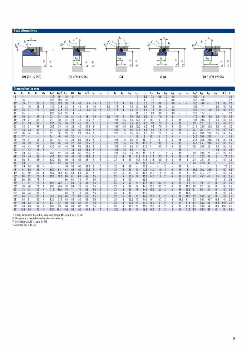
Dimensions in mmd1 d3 d6 d7 d8 d111) d121) d13 db l1N l33) l5 l6 l7 l8 l9 l10 l11 l12 l13 l14 l15 l16 l18 l19 l213) l22 l23 l28 b2) R6 14 – – – 11.5 16 16 8 – – – – – – – – 9 6.5 7.1 5.6 1.2 3.8 – – 10.5 11.9 – – – 1.28 18 – – – 15.5 19.2 18 11 – – – – – – – – 9 8 7.1 7 1.2 3.8 – – 15.5 16.9 – – – 1.2
10* 19 17 21 3 15.5 19.2 20 13 40 15.5 1.5 4 8.5 17.5 10 7.5 9 7.5 7.1 6.6 1.2 3.8 – – 15.5 16.9 – 6.6 (8) 1.212* 21 19 23 3 17.5 21.6 22 16 40 16 1.5 4 8.5 17.5 10 7.5 10 6.5 7.6 5.6 1.2 3.8 – – 15.5 17.4 – 6.6 (8) 1.214* 23 21 25 3 20.5 24.6 24 18 40 16.5 1.5 4 8.5 17.5 10 7.5 10 6.5 7.6 5.6 1.2 3.8 – – 15.5 17.4 16.5 6.6 (8) 1.215 24 – – – 20.5 24.6 25 19 – – – – – – – – 11 7.5 8.6 6.6 1.2 3.8 – – 15.5 17.4 – – – 1.216* 26 23 27 3 22 28 26 21 40 18 1.5 4 8.5 17.5 10 7.5 11.5 8.5 9 7.5 1.5 5 – – 17.5 19.5 16.5 6.6 (8) 1.518* 29 27 33 3 24 30 31 23 45 19.5 2 5 9 19.5 11.5 8.5 12.5 9 10 8 1.5 5 15 7 18.5 20.5 18 7.5 (8) 1.520* 31 29 35 3 29.5 35 34 26 45 22 2 5 9 19.5 11.5 8.5 12.5 8.5 9.5 7.5 1.5 5 15 7 20 22 19 7.5 (8) 1.522* 33 31 37 3 29.5 35 36 28 45 21.5 2 5 9 19.5 11.5 8.5 12.5 8.5 9.5 7.5 1.5 5 15 7 21.5 23.5 20.5 7.5 (8) 1.524* 35 33 39 3 32 38 38 30 50 23.5 2 5 9 19.5 11.5 8.5 12.5 8.5 9.5 7.5 1.5 5 15 7 23 25 22 7.5 (8) 1.525* 36 34 40 3 32 38 39 31 50 26.5 2 5 9 19.5 11.5 8.5 12.5 8.5 9.5 7.5 1.5 5 15 7 24.5 26.5 23.5 7.5 (8) 1.526 37 – – – 34 40 40 32 – – – – 9 – – – 13 9 10 8 1.5 5 – – 24.5 26.5 23.5 – – 1.528* 40 37 43 3 36 42 42 35 50 26.5 2 5 9 19.5 11.5 8.5 14 10 11 9 1.5 5 15 7 24.5 26.5 24.5 7.5 (8) 1.530* 43 39 45 3 39.2 45 44 37 50 26.5 2 5 9 19.5 11.5 8.5 14 11.5 11 10.5 1.5 5 15 7 24.5 25 24.5 7.5 (8) 1.532* 46 42 48 3 42.2 48 46 39 55 28.5 2 5 9 19.5 11.5 8.5 14 11.5 11 10.5 1.5 5 15 7 28 28.5 28 7.5 (8) 1.533* 47 42 48 3 – – 47 40 55 28.5 2 5 9 19.5 11.5 8.5 – 12 – – – – 15 7 – – – 7.5 (8) 1.535* 49 44 50 3 46.2 52 49 43 55 28.5 2 5 9 19.5 11.5 8.5 14.5 12 11.5 11 1.5 5 15 7 28 28.5 28 7.5 (8) 1.538* 53 49 56 4 49.2 55 54 45 55 33.5 2 6 9 22 14 10 14.5 11.3 11.5 10.3 1.5 5 16 8 31 32.2 31 9 7.5 1.540* 56 51 58 4 52.2 58 56 49 55 36 2 6 9 22 14 10 14.5 11.8 11.5 10.8 1.5 5 16 8 34 34.7 34 9 (8) 1.542 59 – – – 53.3 62 58 52 – – – – 9 – – – 17 13.2 14.3 12 2 6 – – 35 37.3 35 – – 2.543* 59 54 61 4 – – 59 52 60 38.5 2 6 9 22 14 10 – 13.2 – – 2 – 16 8 – – – 9 7.5 2.545* 61 56 63 4 55.3 64 61 55 60 39.5 2 6 9 22 14 10 17 12.8 14.3 11.6 2 6 16 8 36.5 39.2 36.5 9 (8) 2.548* 64 59 66 4 59.7 68.4 64 58 60 46 2 6 9 22 14 10 17 12.8 14.3 11.6 2 6 16 8 42 44.7 42 9 (8) 2.550* 66 62 70 4 60.8 69.3 66 61 60 45 2.5 6 9 23 15 10.5 17 12.8 14.3 11.6 2 6 17 9.5 43 45.7 43 9.5 (8) 2.553* 69 65 73 4 – – 69 64 70 47 2.5 6 9 23 15 12 – 13.5 – – – – 17 9.5 – – – 11 8 2.555* 71 67 75 4 66.5 75.4 71 66 70 49 2.5 6 9 23 15 12 18 14.5 15.3 13.3 2 6 17 9.5 47 49 47 11 (8) 2.558* 76 70 78 4 69.5 78.4 78 69 70 55 2.5 6 9 23 15 12 18 14.5 15.3 13.3 2 6 18 10.5 50 52 50 11 (8) 2.560* 78 72 80 4 71.5 80.4 79 71 70 55 2.5 6 9 23 15 12 18 14.5 15.3 13.3 2 6 18 10.5 51 55 51 11 (8) 2.563* 83 75 83 4 – – 83 74 70 55 2.5 6 9 23 15 12 – 14.2 – – – – 18 10.5 – – – 11 (8) 2.565* 84 77 85 4 76.5 85.4 85 77 80 55 2.5 6 9 23 15 12 18 14.2 15.3 13 2 6 18 10.5 52 54.3 52 11 (8) 2.568* 88 81 90 4 82.7 91.5 88 80 80 55 2.5 7 9 26 18 12.5 19 14.9 16 13.7 2 6 18.5 11 53 55.3 52.7 11.3 (8) 2.570* 90 83 92 4 83 92 90 83 80 57 2.5 7 9 26 18 12.5 18 14.2 15.3 13 2 6 19 11.5 54 56.3 54 11.3 (10) 2.575* 98 88 97 4 90.2 99 98 88 80 62 2.5 7 9 26 18 12.5 18 15.2 15.3 14 2 6 19 11.5 55 56.3 54 11.3 (10) 2.580* 100 95 105 4 95.2 104 103 93 90 61.8 3 7 9 26.2 18.2 13 19 16.2 16.3 15 2 6 19 11.5 58 59.3 58 12 10 2.5
1) Fitting dimensions d11 and d12 only apply to type M37G with d1 >16 mm2) Dimensions in brackets lie either above or below l1N3) l3 valid for M3...N, l21 valid for M3* According to EN 12756
G9 (EN 12756) G6 (EN 12756) G4 G13 G16 (EN 12756)
Seat alternatives
d 7
H8
d 6
H11
l6l5
20°
G9 © EagleBurgmann
l28
l10
d7
H8
d6
H11
l6 l5
20°
G6 (M32N4) © EagleBurgmann
30°
l16l15 R
G4 © EagleBurgmann
l12
l14
d 11
+0,1
d 12
H7
G13 (M3) © EagleBurgmann
30°
l16l15
l13l11
R
d 11
+0,1
d 12
H7
d 7
H8
d 6
H11
l6l5
20°
l19
l18
G16 © EagleBurgmann
10
1.6 1.5 1.4 1.1 2 3
1.2 1.3
d 3 d 1 h6
(>10
0 =
h8)
l3 l8
l9f
m x
d820°
1)
l5 l6
l1k l7 +0,5
M7N © EagleBurgmann
d 6 H1
1 2
)
d 7 H8
3)
1) d1 >100 mm: 30°2) d1 >100 mm: +0.13) d1 >100 mm: H7
G9 (EN 12756) G6 (EN 12756) G4 G13 G16 (EN 12756, but l1k is shorter than specified)
Seat alternatives
20°
l6l5
d 6
H11
d 7
H8
G9 (M7N) © EagleBurgmann
l28
l10
d7
H8
d6
H11
l6 l5
20°
G6 (M32N4) © EagleBurgmann
30°
l16l15 R
G4 © EagleBurgmann
l12
l14
d 11
+0,1
d 12
H7
G13 (M3) © EagleBurgmann
30°
l16l15
l13l11
R
d 11
+0,1
d 12
H7
d 7
H8
d 6
H11
l6l5
20°
l19
l18
G16 © EagleBurgmann
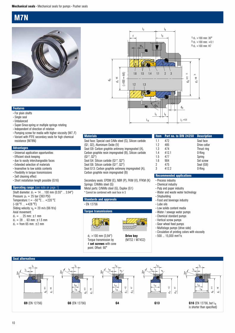
d1 >100 mm (3,94")Torque transmission by 4 set screws with cone point. Offset: 90°
Drive key(M7S2 / M74S2)
Torque transmissions
Set screw with cone point © EagleBurgmann
Torque transmission
Torque transmission
Drive key © EagleBurgmann
M7N
Mechanical seals • Mechanical seals for pumps • Pusher seals
Item Part no. to DIN 24250 Description1.1 472 Seal face1.2 485 Drive collar1.3 474 Thrust ring1.4 412.1 O-Ring1.5 477 Spring1.6 904 Set screw2 475 Seat (G9)3 412.2 O-Ring
Recommended applications• Process industry• Chemical industry• Pulp and paper industry• Water and waste water technology• Shipbuilding• Food and beverage industry• Lube oils• Low solids content media• Water / sewage water pumps• Chemical standard pumps• Vertical screw pumps• Gear wheel feed pumps• Multistage pumps (drive side)• Circulation of printing colors with viscosity • 500 ... 15,000 mm2/s
MaterialsSeal face: Special cast CrMo steel (S), Silicon carbide (Q1, Q2), Aluminium Oxide (V)Seat G9: Carbon graphite antimony impregnated (A), Carbon graphite resin impregnated (B), Silicon carbide (Q1*, Q2*) Seat G4: Silicon carbide (Q1*, Q2*) Seat G6: Silicon carbide (Q1*, Q2*) Seat G13: Carbon graphite antimony impregnated (A), Carbon graphite resin impregnated (B)
Secondary seals: EPDM (E), NBR (P), FKM (V), FFKM (K)Springs: CrNiMo steel (G)Metal parts: CrNiMo steel (G), Duplex (G1)* Cannot be combined with seal face in S
Standards and approvals• EN 12756
Features• For plain shafts• Single seal• Unbalanced• Super-Sinus-spring or multiple springs rotating• Independent of direction of rotation• Pumping screw for media with higher viscosity (M7..F)• Variant with PTFE secondary seals for high chemical resistance (M78N)
Advantages• Universal application opportunities• Efficient stock keeping • due to easily interchangeable faces• Extended selection of materials• Insensitive to low solids contents• Flexibility in torque transmissions• Self cleaning effect• Short installation length possible (G16)
Operating range (see note on page 1)Shaft diameter: d1 = 14 … 100 mm (0.55" … 3.94")Pressure: p1 = 25 bar (363 PSI)Temperature: t = –50 °C … +220 °C (–58 °F … +428 °F)Sliding velocity: vg = 20 m/s (66 ft/s)Axial movement:d1 = … 25 mm: ±1 mmd1 = 28 … 63 mm: ±1.5 mmd1 = from 65 mm: ±2 mm
11
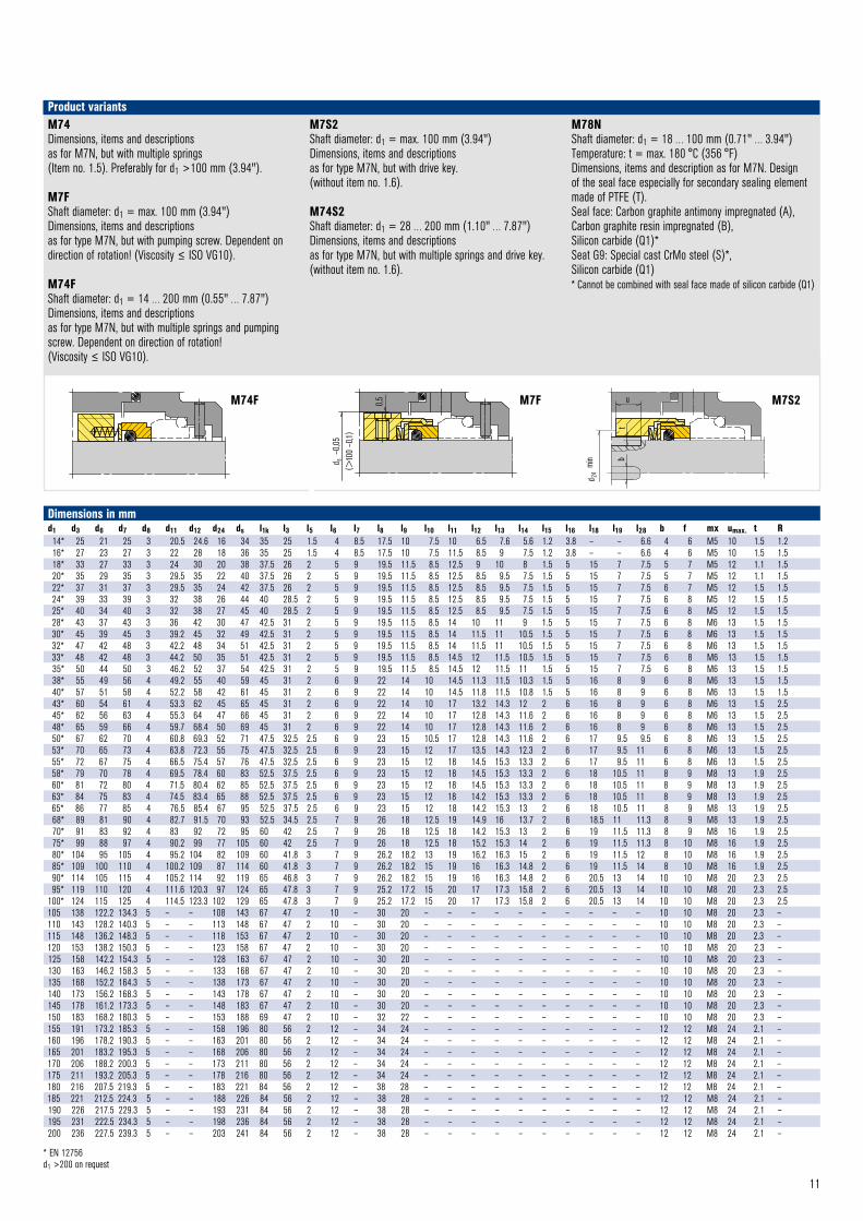
Dimensions in mmd1 d3 d6 d7 d8 d11 d12 d24 ds l1k l3 l5 l6 l7 l8 l9 l10 l11 l12 l13 l14 l15 l16 l18 l19 l28 b f mx umax. t R14* 25 21 25 3 20.5 24.6 16 34 35 25 1.5 4 8.5 17.5 10 7.5 10 6.5 7.6 5.6 1.2 3.8 – – 6.6 4 6 M5 10 1.5 1.216* 27 23 27 3 22 28 18 36 35 25 1.5 4 8.5 17.5 10 7.5 11.5 8.5 9 7.5 1.2 3.8 – – 6.6 4 6 M5 10 1.5 1.518* 33 27 33 3 24 30 20 38 37.5 26 2 5 9 19.5 11.5 8.5 12.5 9 10 8 1.5 5 15 7 7.5 5 7 M5 12 1.1 1.520* 35 29 35 3 29.5 35 22 40 37.5 26 2 5 9 19.5 11.5 8.5 12.5 8.5 9.5 7.5 1.5 5 15 7 7.5 5 7 M5 12 1.1 1.522* 37 31 37 3 29.5 35 24 42 37.5 26 2 5 9 19.5 11.5 8.5 12.5 8.5 9.5 7.5 1.5 5 15 7 7.5 6 7 M5 12 1.5 1.524* 39 33 39 3 32 38 26 44 40 28.5 2 5 9 19.5 11.5 8.5 12.5 8.5 9.5 7.5 1.5 5 15 7 7.5 6 8 M5 12 1.5 1.525* 40 34 40 3 32 38 27 45 40 28.5 2 5 9 19.5 11.5 8.5 12.5 8.5 9.5 7.5 1.5 5 15 7 7.5 6 8 M5 12 1.5 1.528* 43 37 43 3 36 42 30 47 42.5 31 2 5 9 19.5 11.5 8.5 14 10 11 9 1.5 5 15 7 7.5 6 8 M6 13 1.5 1.530* 45 39 45 3 39.2 45 32 49 42.5 31 2 5 9 19.5 11.5 8.5 14 11.5 11 10.5 1.5 5 15 7 7.5 6 8 M6 13 1.5 1.532* 47 42 48 3 42.2 48 34 51 42.5 31 2 5 9 19.5 11.5 8.5 14 11.5 11 10.5 1.5 5 15 7 7.5 6 8 M6 13 1.5 1.533* 48 42 48 3 44.2 50 35 51 42.5 31 2 5 9 19.5 11.5 8.5 14.5 12 11.5 10.5 1.5 5 15 7 7.5 6 8 M6 13 1.5 1.535* 50 44 50 3 46.2 52 37 54 42.5 31 2 5 9 19.5 11.5 8.5 14.5 12 11.5 11 1.5 5 15 7 7.5 6 8 M6 13 1.5 1.538* 55 49 56 4 49.2 55 40 59 45 31 2 6 9 22 14 10 14.5 11.3 11.5 10.3 1.5 5 16 8 9 6 8 M6 13 1.5 1.540* 57 51 58 4 52.2 58 42 61 45 31 2 6 9 22 14 10 14.5 11.8 11.5 10.8 1.5 5 16 8 9 6 8 M6 13 1.5 1.543* 60 54 61 4 53.3 62 45 65 45 31 2 6 9 22 14 10 17 13.2 14.3 12 2 6 16 8 9 6 8 M6 13 1.5 2.545* 62 56 63 4 55.3 64 47 66 45 31 2 6 9 22 14 10 17 12.8 14.3 11.6 2 6 16 8 9 6 8 M6 13 1.5 2.548* 65 59 66 4 59.7 68.4 50 69 45 31 2 6 9 22 14 10 17 12.8 14.3 11.6 2 6 16 8 9 6 8 M6 13 1.5 2.550* 67 62 70 4 60.8 69.3 52 71 47.5 32.5 2.5 6 9 23 15 10.5 17 12.8 14.3 11.6 2 6 17 9.5 9.5 6 8 M6 13 1.5 2.553* 70 65 73 4 63.8 72.3 55 75 47.5 32.5 2.5 6 9 23 15 12 17 13.5 14.3 12.3 2 6 17 9.5 11 6 8 M6 13 1.5 2.555* 72 67 75 4 66.5 75.4 57 76 47.5 32.5 2.5 6 9 23 15 12 18 14.5 15.3 13.3 2 6 17 9.5 11 6 8 M6 13 1.5 2.558* 79 70 78 4 69.5 78.4 60 83 52.5 37.5 2.5 6 9 23 15 12 18 14.5 15.3 13.3 2 6 18 10.5 11 8 9 M8 13 1.9 2.560* 81 72 80 4 71.5 80.4 62 85 52.5 37.5 2.5 6 9 23 15 12 18 14.5 15.3 13.3 2 6 18 10.5 11 8 9 M8 13 1.9 2.563* 84 75 83 4 74.5 83.4 65 88 52.5 37.5 2.5 6 9 23 15 12 18 14.2 15.3 13.3 2 6 18 10.5 11 8 9 M8 13 1.9 2.565* 86 77 85 4 76.5 85.4 67 95 52.5 37.5 2.5 6 9 23 15 12 18 14.2 15.3 13 2 6 18 10.5 11 8 9 M8 13 1.9 2.568* 89 81 90 4 82.7 91.5 70 93 52.5 34.5 2.5 7 9 26 18 12.5 19 14.9 16 13.7 2 6 18.5 11 11.3 8 9 M8 13 1.9 2.570* 91 83 92 4 83 92 72 95 60 42 2.5 7 9 26 18 12.5 18 14.2 15.3 13 2 6 19 11.5 11.3 8 9 M8 16 1.9 2.575* 99 88 97 4 90.2 99 77 105 60 42 2.5 7 9 26 18 12.5 18 15.2 15.3 14 2 6 19 11.5 11.3 8 10 M8 16 1.9 2.580* 104 95 105 4 95.2 104 82 109 60 41.8 3 7 9 26.2 18.2 13 19 16.2 16.3 15 2 6 19 11.5 12 8 10 M8 16 1.9 2.585* 109 100 110 4 100.2 109 87 114 60 41.8 3 7 9 26.2 18.2 15 19 16 16.3 14.8 2 6 19 11.5 14 8 10 M8 16 1.9 2.590* 114 105 115 4 105.2 114 92 119 65 46.8 3 7 9 26.2 18.2 15 19 16 16.3 14.8 2 6 20.5 13 14 10 10 M8 20 2.3 2.595* 119 110 120 4 111.6 120.3 97 124 65 47.8 3 7 9 25.2 17.2 15 20 17 17.3 15.8 2 6 20.5 13 14 10 10 M8 20 2.3 2.5
100* 124 115 125 4 114.5 123.3 102 129 65 47.8 3 7 9 25.2 17.2 15 20 17 17.3 15.8 2 6 20.5 13 14 10 10 M8 20 2.3 2.5105 138 122.2 134.3 5 – – 108 143 67 47 2 10 – 30 20 – – – – – – – – – – 10 10 M8 20 2.3 –110 143 128.2 140.3 5 – – 113 148 67 47 2 10 – 30 20 – – – – – – – – – – 10 10 M8 20 2.3 –115 148 136.2 148.3 5 – – 118 153 67 47 2 10 – 30 20 – – – – – – – – – – 10 10 M8 20 2.3 –120 153 138.2 150.3 5 – – 123 158 67 47 2 10 – 30 20 – – – – – – – – – – 10 10 M8 20 2.3 –125 158 142.2 154.3 5 – – 128 163 67 47 2 10 – 30 20 – – – – – – – – – – 10 10 M8 20 2.3 –130 163 146.2 158.3 5 – – 133 168 67 47 2 10 – 30 20 – – – – – – – – – – 10 10 M8 20 2.3 –135 168 152.2 164.3 5 – – 138 173 67 47 2 10 – 30 20 – – – – – – – – – – 10 10 M8 20 2.3 –140 173 156.2 168.3 5 – – 143 178 67 47 2 10 – 30 20 – – – – – – – – – – 10 10 M8 20 2.3 –145 178 161.2 173.3 5 – – 148 183 67 47 2 10 – 30 20 – – – – – – – – – – 10 10 M8 20 2.3 –150 183 168.2 180.3 5 – – 153 188 69 47 2 10 – 32 22 – – – – – – – – – – 10 10 M8 20 2.3 –155 191 173.2 185.3 5 – – 158 196 80 56 2 12 – 34 24 – – – – – – – – – – 12 12 M8 24 2.1 –160 196 178.2 190.3 5 – – 163 201 80 56 2 12 – 34 24 – – – – – – – – – – 12 12 M8 24 2.1 –165 201 183.2 195.3 5 – – 168 206 80 56 2 12 – 34 24 – – – – – – – – – – 12 12 M8 24 2.1 –170 206 188.2 200.3 5 – – 173 211 80 56 2 12 – 34 24 – – – – – – – – – – 12 12 M8 24 2.1 –175 211 193.2 205.3 5 – – 178 216 80 56 2 12 – 34 24 – – – – – – – – – – 12 12 M8 24 2.1 –180 216 207.5 219.3 5 – – 183 221 84 56 2 12 – 38 28 – – – – – – – – – – 12 12 M8 24 2.1 –185 221 212.5 224.3 5 – – 188 226 84 56 2 12 – 38 28 – – – – – – – – – – 12 12 M8 24 2.1 –190 226 217.5 229.3 5 – – 193 231 84 56 2 12 – 38 28 – – – – – – – – – – 12 12 M8 24 2.1 –195 231 222.5 234.3 5 – – 198 236 84 56 2 12 – 38 28 – – – – – – – – – – 12 12 M8 24 2.1 –200 236 227.5 239.3 5 – – 203 241 84 56 2 12 – 38 28 – – – – – – – – – – 12 12 M8 24 2.1 –
* EN 12756d1 >200 on request
M74Dimensions, items and descriptionsas for M7N, but with multiple springs(Item no. 1.5). Preferably for d1 >100 mm (3.94").
M7FShaft diameter: d1 = max. 100 mm (3.94")Dimensions, items and descriptions as for type M7N, but with pumping screw. Dependent on direction of rotation! (Viscosity ≤ ISO VG10).
M74FShaft diameter: d1 = 14 … 200 mm (0.55" … 7.87")Dimensions, items and descriptionsas for type M7N, but with multiple springs and pumping screw. Dependent on direction of rotation!(Viscosity ≤ ISO VG10).
M7S2Shaft diameter: d1 = max. 100 mm (3.94")Dimensions, items and descriptionsas for type M7N, but with drive key.(without item no. 1.6).
M74S2Shaft diameter: d1 = 28 … 200 mm (1.10" … 7.87")Dimensions, items and descriptionsas for type M7N, but with multiple springs and drive key.(without item no. 1.6).
M78NShaft diameter: d1 = 18 … 100 mm (0.71" … 3.94")Temperature: t = max. 180 °C (356 °F)Dimensions, items and description as for M7N. Design of the seal face especially for secondary sealing element made of PTFE (T).Seal face: Carbon graphite antimony impregnated (A), Carbon graphite resin impregnated (B), Silicon carbide (Q1)*Seat G9: Special cast CrMo steel (S)*, Silicon carbide (Q1)* Cannot be combined with seal face made of silicon carbide (Q1)
Product variants
M74F M7F
b
d 24
min
u
M7S2 © EagleBurgmann
t
M7S2
M7F © EagleBurgmann
0,5
d s –
0,05
( >10
0 –0
,1)
M74F © EagleBurgmann
12
G4
Seat alternatives
l28
l10
d7
H8
d6
H11
l6 l5
20°
G6 (M32N4) © EagleBurgmann
30°
l16l15 R
G4 © EagleBurgmann
l12
l14
d 11
+0,1
d 12
H7
G13 (M3) © EagleBurgmann
30°
l16l15
l13l11
R
d 11
+0,1
d 12
H7
Torque transmissions
Set screw with cone point © EagleBurgmann
1) d1 >100 mm: 30°2) d1 >100 mm: +0.13) d1 >100 mm: H7
G6 (EN 12756)
d1 >100 mm (3,94") Torque transmission by 4 set screws with cone point. Offset: 90°
Spring loaded drive pin (M74-D22)
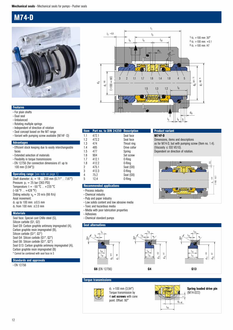
M74-D
Mechanical seals • Mechanical seals for pumps • Pusher seals
Item Part no. to DIN 24250 Description1.1 472.1 Seal face1.2 472.2 Seal face1.3 474 Thrust ring1.4 485 Drive collar1.5 477 Spring1.6 904 Set screw1.7 412.1 O-Ring1.8 412.2 O-Ring2 475.1 Seat (G9)3 412.3 O-Ring4 75.2 Seat (G9)5 12.4 O-Ring
Recommended applications• Process industry• Chemical industry• Pulp and paper industry• Low solids content and low abrasive media• Toxic and hazardous media• Media with poor lubrication properties• Adhesives• Chemical standard pumps
M74F-DDimensions, items and descriptionsas for M74-D, but with pumping screw (Item no. 1.4). (Viscosity ≤ ISO VG10). Dependent on direction of rotation.
Product variant
ds
–0,
05
(>10
0 –
0,1)
0,5
M74F – D © EagleBurgmann
3 2 1.1 1.7 1.6 1.4 1.8 4 5
1.5 1.3 1.2 l8
l5 l6
d8
5
d 6 H1
1 2
)
d 7 H8
3)
d 3
d 1 h6
(>10
0 =
h8)
l1
l3
l31l9 l4
l7 +0,5
mx
20° 1
)
M74 – D © EagleBurgmann
DrehmomentübertragungSchapper © EagleBurgmann
l35
d9 e8
t
Features• For plain shafts• Dual seal• Unbalanced• Rotating multiple springs• Independent of direction of rotation• Seal concept based on the M7 range• Variant with pumping screw available (M74F - D)
Advantages• Efficient stock keeping due to easily interchangeable faces
• Extended selection of materials• Flexibility in torque transmissions• EN 12756 (for connection dimensions d1 up to 100 mm (3.94"))
Operating range (see note on page 1)Shaft diameter: d1 = 18 … 200 mm (0.71" … 7.87")Pressure: p1 = 25 bar (363 PSI)Temperature: t = –50 °C … +220 °C (–58 °F … +428 °F)Sliding velocity: vg = 20 m/s (66 ft/s)Axial movement:d1 up to 100 mm: ±0.5 mmd1 from 100 mm: ±2.0 mm
MaterialsSeal face: Special cast CrMo steel (S), Silicon carbide (Q1, Q2)Seat G9: Carbon graphite antimony impregnated (A), Carbon graphite resin impregnated (B), Silicon carbide (Q1*, Q2*) Seat G4: Silicon carbide (Q1*, Q2*) Seat G6: Silicon carbide (Q1*, Q2*) Seat G13: Carbon graphite antimony impregnated (A), Carbon graphite resin impregnated (B)* Cannot be combined with seal face in S
Standards and approvals• EN 12756
G13
13
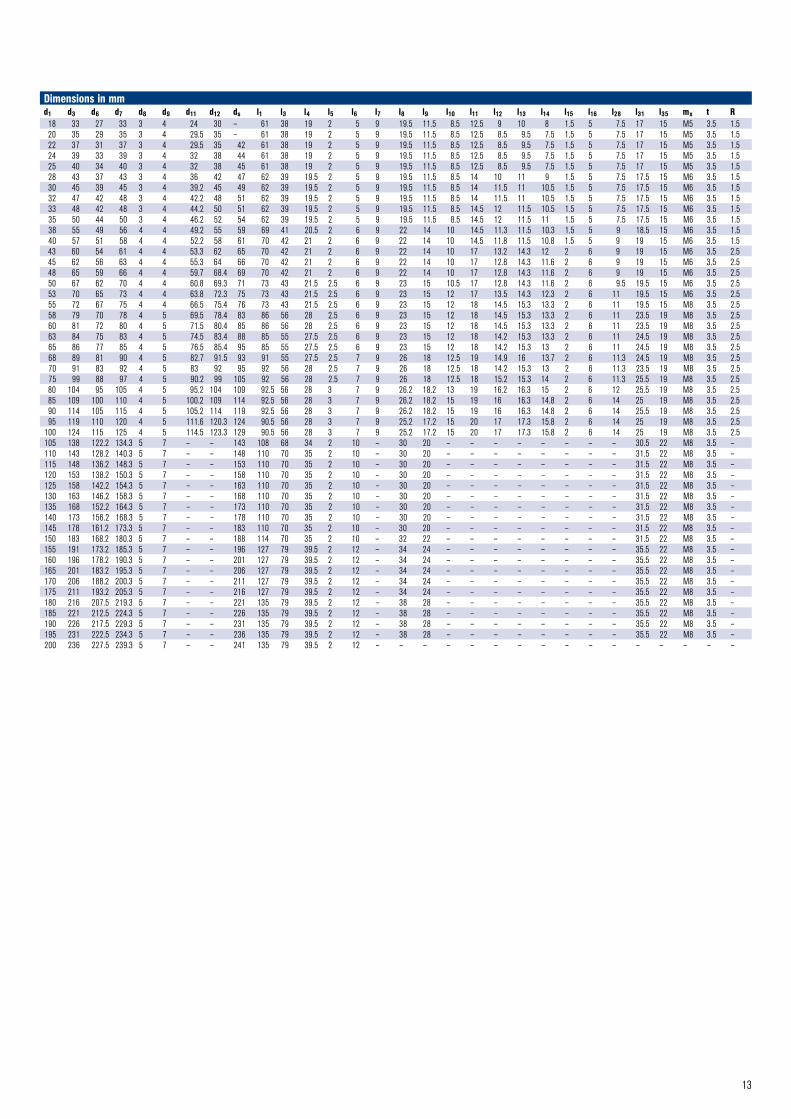
Dimensions in mmd1 d3 d6 d7 d8 d9 d11 d12 ds l1 l3 l4 l5 l6 l7 l8 l9 l10 l11 l12 l13 l14 l15 l16 l28 l31 l35 mx t R18 33 27 33 3 4 24 30 – 61 38 19 2 5 9 19.5 11.5 8.5 12.5 9 10 8 1.5 5 7.5 17 15 M5 3.5 1.520 35 29 35 3 4 29.5 35 – 61 38 19 2 5 9 19.5 11.5 8.5 12.5 8.5 9.5 7.5 1.5 5 7.5 17 15 M5 3.5 1.522 37 31 37 3 4 29.5 35 42 61 38 19 2 5 9 19.5 11.5 8.5 12.5 8.5 9.5 7.5 1.5 5 7.5 17 15 M5 3.5 1.524 39 33 39 3 4 32 38 44 61 38 19 2 5 9 19.5 11.5 8.5 12.5 8.5 9.5 7.5 1.5 5 7.5 17 15 M5 3.5 1.525 40 34 40 3 4 32 38 45 61 38 19 2 5 9 19.5 11.5 8.5 12.5 8.5 9.5 7.5 1.5 5 7.5 17 15 M5 3.5 1.528 43 37 43 3 4 36 42 47 62 39 19.5 2 5 9 19.5 11.5 8.5 14 10 11 9 1.5 5 7.5 17.5 15 M6 3.5 1.530 45 39 45 3 4 39.2 45 49 62 39 19.5 2 5 9 19.5 11.5 8.5 14 11.5 11 10.5 1.5 5 7.5 17.5 15 M6 3.5 1.532 47 42 48 3 4 42.2 48 51 62 39 19.5 2 5 9 19.5 11.5 8.5 14 11.5 11 10.5 1.5 5 7.5 17.5 15 M6 3.5 1.533 48 42 48 3 4 44.2 50 51 62 39 19.5 2 5 9 19.5 11.5 8.5 14.5 12 11.5 10.5 1.5 5 7.5 17.5 15 M6 3.5 1.535 50 44 50 3 4 46.2 52 54 62 39 19.5 2 5 9 19.5 11.5 8.5 14.5 12 11.5 11 1.5 5 7.5 17.5 15 M6 3.5 1.538 55 49 56 4 4 49.2 55 59 69 41 20.5 2 6 9 22 14 10 14.5 11.3 11.5 10.3 1.5 5 9 18.5 15 M6 3.5 1.540 57 51 58 4 4 52.2 58 61 70 42 21 2 6 9 22 14 10 14.5 11.8 11.5 10.8 1.5 5 9 19 15 M6 3.5 1.543 60 54 61 4 4 53.3 62 65 70 42 21 2 6 9 22 14 10 17 13.2 14.3 12 2 6 9 19 15 M6 3.5 2.545 62 56 63 4 4 55.3 64 66 70 42 21 2 6 9 22 14 10 17 12.8 14.3 11.6 2 6 9 19 15 M6 3.5 2.548 65 59 66 4 4 59.7 68.4 69 70 42 21 2 6 9 22 14 10 17 12.8 14.3 11.6 2 6 9 19 15 M6 3.5 2.550 67 62 70 4 4 60.8 69.3 71 73 43 21.5 2.5 6 9 23 15 10.5 17 12.8 14.3 11.6 2 6 9.5 19.5 15 M6 3.5 2.553 70 65 73 4 4 63.8 72.3 75 73 43 21.5 2.5 6 9 23 15 12 17 13.5 14.3 12.3 2 6 11 19.5 15 M6 3.5 2.555 72 67 75 4 4 66.5 75.4 76 73 43 21.5 2.5 6 9 23 15 12 18 14.5 15.3 13.3 2 6 11 19.5 15 M8 3.5 2.558 79 70 78 4 5 69.5 78.4 83 86 56 28 2.5 6 9 23 15 12 18 14.5 15.3 13.3 2 6 11 23.5 19 M8 3.5 2.560 81 72 80 4 5 71.5 80.4 85 86 56 28 2.5 6 9 23 15 12 18 14.5 15.3 13.3 2 6 11 23.5 19 M8 3.5 2.563 84 75 83 4 5 74.5 83.4 88 85 55 27.5 2.5 6 9 23 15 12 18 14.2 15.3 13.3 2 6 11 24.5 19 M8 3.5 2.565 86 77 85 4 5 76.5 85.4 95 85 55 27.5 2.5 6 9 23 15 12 18 14.2 15.3 13 2 6 11 24.5 19 M8 3.5 2.568 89 81 90 4 5 82.7 91.5 93 91 55 27.5 2.5 7 9 26 18 12.5 19 14.9 16 13.7 2 6 11.3 24.5 19 M8 3.5 2.570 91 83 92 4 5 83 92 95 92 56 28 2.5 7 9 26 18 12.5 18 14.2 15.3 13 2 6 11.3 23.5 19 M8 3.5 2.575 99 88 97 4 5 90.2 99 105 92 56 28 2.5 7 9 26 18 12.5 18 15.2 15.3 14 2 6 11.3 25.5 19 M8 3.5 2.580 104 95 105 4 5 95.2 104 109 92.5 56 28 3 7 9 26.2 18.2 13 19 16.2 16.3 15 2 6 12 25.5 19 M8 3.5 2.585 109 100 110 4 5 100.2 109 114 92.5 56 28 3 7 9 26.2 18.2 15 19 16 16.3 14.8 2 6 14 25 19 M8 3.5 2.590 114 105 115 4 5 105.2 114 119 92.5 56 28 3 7 9 26.2 18.2 15 19 16 16.3 14.8 2 6 14 25.5 19 M8 3.5 2.595 119 110 120 4 5 111.6 120.3 124 90.5 56 28 3 7 9 25.2 17.2 15 20 17 17.3 15.8 2 6 14 25 19 M8 3.5 2.5
100 124 115 125 4 5 114.5 123.3 129 90.5 56 28 3 7 9 25.2 17.2 15 20 17 17.3 15.8 2 6 14 25 19 M8 3.5 2.5105 138 122.2 134.3 5 7 – – 143 108 68 34 2 10 – 30 20 – – – – – – – – 30.5 22 M8 3.5 –110 143 128.2 140.3 5 7 – – 148 110 70 35 2 10 – 30 20 – – – – – – – – 31.5 22 M8 3.5 –115 148 136.2 148.3 5 7 – – 153 110 70 35 2 10 – 30 20 – – – – – – – – 31.5 22 M8 3.5 –120 153 138.2 150.3 5 7 – – 158 110 70 35 2 10 – 30 20 – – – – – – – – 31.5 22 M8 3.5 –125 158 142.2 154.3 5 7 – – 163 110 70 35 2 10 – 30 20 – – – – – – – – 31.5 22 M8 3.5 –130 163 146.2 158.3 5 7 – – 168 110 70 35 2 10 – 30 20 – – – – – – – – 31.5 22 M8 3.5 –135 168 152.2 164.3 5 7 – – 173 110 70 35 2 10 – 30 20 – – – – – – – – 31.5 22 M8 3.5 –140 173 156.2 168.3 5 7 – – 178 110 70 35 2 10 – 30 20 – – – – – – – – 31.5 22 M8 3.5 –145 178 161.2 173.3 5 7 – – 183 110 70 35 2 10 – 30 20 – – – – – – – – 31.5 22 M8 3.5 –150 183 168.2 180.3 5 7 – – 188 114 70 35 2 10 – 32 22 – – – – – – – – 31.5 22 M8 3.5 –155 191 173.2 185.3 5 7 – – 196 127 79 39.5 2 12 – 34 24 – – – – – – – – 35.5 22 M8 3.5 –160 196 178.2 190.3 5 7 – – 201 127 79 39.5 2 12 – 34 24 – – – – – – – – 35.5 22 M8 3.5 –165 201 183.2 195.3 5 7 – – 206 127 79 39.5 2 12 – 34 24 – – – – – – – – 35.5 22 M8 3.5 –170 206 188.2 200.3 5 7 – – 211 127 79 39.5 2 12 – 34 24 – – – – – – – – 35.5 22 M8 3.5 –175 211 193.2 205.3 5 7 – – 216 127 79 39.5 2 12 – 34 24 – – – – – – – – 35.5 22 M8 3.5 –180 216 207.5 219.3 5 7 – – 221 135 79 39.5 2 12 – 38 28 – – – – – – – – 35.5 22 M8 3.5 –185 221 212.5 224.3 5 7 – – 226 135 79 39.5 2 12 – 38 28 – – – – – – – – 35.5 22 M8 3.5 –190 226 217.5 229.3 5 7 – – 231 135 79 39.5 2 12 – 38 28 – – – – – – – – 35.5 22 M8 3.5 –195 231 222.5 234.3 5 7 – – 236 135 79 39.5 2 12 – 38 28 – – – – – – – – 35.5 22 M8 3.5 –200 236 227.5 239.3 5 7 – – 241 135 79 39.5 2 12 – – – – – – – – – – – – – – – –
14
1) d1 >100 mm: 2 mm x 30°2) d1 >100 mm: 30°3) d1 >100 mm: +0.14) d1 >100 mm: H7
± 2 ... 4 mm
l1k
±4 mm
l1N
H76 © EagleBurgmann
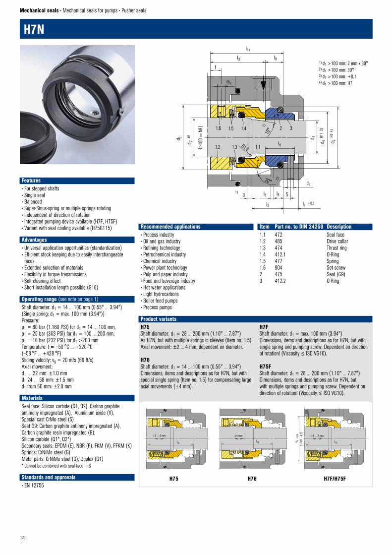
H7N
Mechanical seals • Mechanical seals for pumps • Pusher seals
H75Shaft diameter: d1 = 28 … 200 mm (1.10" … 7.87")As H7N, but with multiple springs in sleeves (Item no. 1.5) Axial movement: ±2 ... 4 mm, dependent on diameter.
H76Shaft diameter: d1 = 14 … 100 mm (0.55" … 3.94")Dimensions, items and descriptions as for H7N, but with special single spring (Item no. 1.5) for compensating large axial movements (±4 mm).
H7FShaft diameter: d1 = max. 100 mm (3.94")Dimensions, items and descriptions as for H7N, but with single spring and pumping screw. Dependent on direction of rotation! (Viscosity ≤ ISO VG10).
H75FShaft diameter: d1 = 28 … 200 mm (1.10" … 7.87")Dimensions, items and descriptions as for H7N, but with multiple springs and pumping screw. Dependent on direction of rotation! (Viscosity ≤ ISO VG10).
Product variants
Recommended applications• Process industry• Oil and gas industry• Refining technology• Petrochemical industry• Chemical industry• Power plant technology• Pulp and paper industry• Food and beverage industry• Hot water applications• Light hydrocarbons• Boiler feed pumps• Process pumps
Item Part no. to DIN 24250 Description1.1 472 Seal face1.2 485 Drive collar1.3 474 Thrust ring1.4 412.1 O-Ring1.5 477 Spring1.6 904 Set screw2 475 Seat (G9)3 412.2 O-Ring
( >10
0 –
0,1)
d s –
0,05 ±1 ... 2 mm
l1K
H7F + H75F © EagleBurgmann
0,5
l1k
l3 l9
f
mx
d 1
d 6 H1
1 3
)
d 7 H8
4)
l8
d820°
2)
1)3 l5
l2
l6 5
l7 +0,5
H7N © EagleBurgmann
d 2 h
6
d 3
(>10
0 =
h8) 1.6 1.5 1.4 2 3
1.2 1.3 R1,6 1.1
10°
1)
Features• For stepped shafts• Single seal• Balanced• Super-Sinus-spring or multiple springs rotating• Independent of direction of rotation• Integrated pumping device available (H7F, H75F)• Variant with seat cooling available (H75G115)
Advantages• Universal application opportunities (standardization)• Efficient stock keeping due to easily interchangeable faces
• Extended selection of materials• Flexibility in torque transmissions• Self cleaning effect• Short Installation length possible (G16)
Operating range (see note on page 1)Shaft diameter: d1 = 14 … 100 mm (0.55" … 3.94")(Single spring: d1 = max. 100 mm (3.94"))Pressure: p1 = 80 bar (1.160 PSI) for d1 = 14 … 100 mm,p1 = 25 bar (363 PSI) for d1 = 100 … 200 mm,p1 = 16 bar (232 PSI) for d1 >200 mmTemperature: t = –50 °C … +220 °C (–58 °F … +428 °F)Sliding velocity: vg = 20 m/s (66 ft/s)Axial movement:d1 … 22 mm: ±1.0 mmd1 24 … 58 mm: ±1.5 mmd1 from 60 mm: ±2.0 mm
MaterialsSeal face: Silicon carbide (Q1, Q2), Carbon graphite antimony impregnated (A), Aluminium oxide (V), Special cast CrMo steel (S)Seat G9: Carbon graphite antimony impregnated (A), Carbon graphite resin impregnated (B), Silicon carbide (Q1*, Q2*) Secondary seals: EPDM (E), NBR (P), FKM (V), FFKM (K)Springs: CrNiMo steel (G)Metal parts: CrNiMo steel (G), Duplex (G1)* Cannot be combined with seal face in S
Standards and approvals• EN 12756
H7F/H75FH76H75
15
Seat alternatives
d1 >100 mm (3.94") Torque transmission by 4 set screws with cone point. Offset: 90°
Torque transmissions
Set screw with cone point © EagleBurgmann
Torque transmission
G9 (EN 12756) G16 (EN 12756, but l1k and l2 are shorter than specified)
G115 Cooled seat especially for hot water applications.
G9 (H7N) © EagleBurgmann
20°
l6l5
d 6
H11
d 7
H8
d 7
H8
d 6
H11
l6l5
20°
l19
l18
G16 © EagleBurgmann
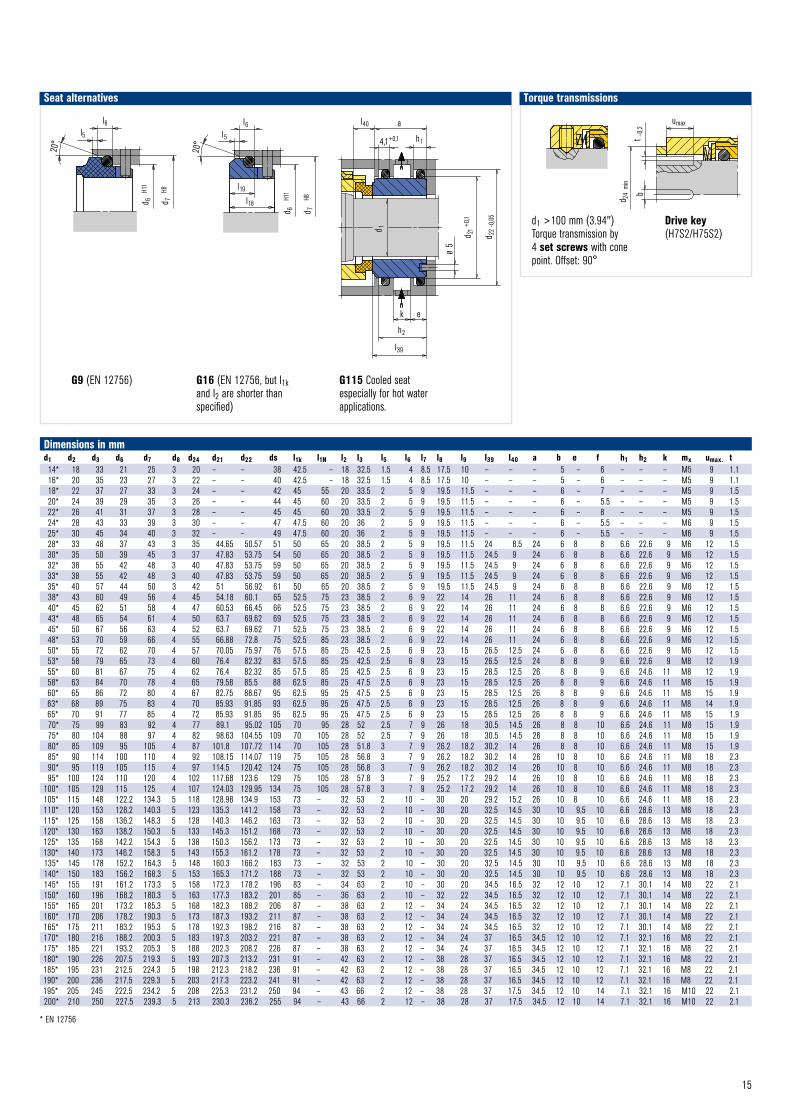
Dimensions in mmd1 d2 d3 d6 d7 d8 d24 d21 d22 ds l1k l1N l2 l3 l5 l6 l7 l8 l9 l39 l40 a b e f h1 h2 k mx umax. t14* 18 33 21 25 3 20 – – 38 42.5 – 18 32.5 1.5 4 8.5 17.5 10 – – – 5 – 6 – – – M5 9 1.116* 20 35 23 27 3 22 – – 40 42.5 – 18 32.5 1.5 4 8.5 17.5 10 – – – 5 – 6 – – – M5 9 1.118* 22 37 27 33 3 24 – – 42 45 55 20 33.5 2 5 9 19.5 11.5 – – – 6 – 7 – – – M5 9 1.520* 24 39 29 35 3 26 – – 44 45 60 20 33.5 2 5 9 19.5 11.5 – – – 6 – 5.5 – – – M5 9 1.522* 26 41 31 37 3 28 – – 45 45 60 20 33.5 2 5 9 19.5 11.5 – – – 6 – 8 – – – M5 9 1.524* 28 43 33 39 3 30 – – 47 47.5 60 20 36 2 5 9 19.5 11.5 – – – 6 – 5.5 – – – M6 9 1.525* 30 45 34 40 3 32 – – 49 47.5 60 20 36 2 5 9 19.5 11.5 – – – 6 – 5.5 – – – M6 9 1.528* 33 48 37 43 3 35 44.65 50.57 51 50 65 20 38.5 2 5 9 19.5 11.5 24 8.5 24 6 8 8 6.6 22.6 9 M6 12 1.530* 35 50 39 45 3 37 47.83 53.75 54 50 65 20 38.5 2 5 9 19.5 11.5 24.5 9 24 6 8 8 6.6 22.6 9 M6 12 1.532* 38 55 42 48 3 40 47.83 53.75 59 50 65 20 38.5 2 5 9 19.5 11.5 24.5 9 24 6 8 8 6.6 22.6 9 M6 12 1.533* 38 55 42 48 3 40 47.83 53.75 59 50 65 20 38.5 2 5 9 19.5 11.5 24.5 9 24 6 8 8 6.6 22.6 9 M6 12 1.535* 40 57 44 50 3 42 51 56.92 61 50 65 20 38.5 2 5 9 19.5 11.5 24.5 9 24 6 8 8 6.6 22.6 9 M6 12 1.538* 43 60 49 56 4 45 54.18 60.1 65 52.5 75 23 38.5 2 6 9 22 14 26 11 24 6 8 8 6.6 22.6 9 M6 12 1.540* 45 62 51 58 4 47 60.53 66.45 66 52.5 75 23 38.5 2 6 9 22 14 26 11 24 6 8 8 6.6 22.6 9 M6 12 1.543* 48 65 54 61 4 50 63.7 69.62 69 52.5 75 23 38.5 2 6 9 22 14 26 11 24 6 8 8 6.6 22.6 9 M6 12 1.545* 50 67 56 63 4 52 63.7 69.62 71 52.5 75 23 38.5 2 6 9 22 14 26 11 24 6 8 8 6.6 22.6 9 M6 12 1.548* 53 70 59 66 4 55 66.88 72.8 75 52.5 85 23 38.5 2 6 9 22 14 26 11 24 6 8 8 6.6 22.6 9 M6 12 1.550* 55 72 62 70 4 57 70.05 75.97 76 57.5 85 25 42.5 2.5 6 9 23 15 26.5 12.5 24 6 8 8 6.6 22.6 9 M6 12 1.553* 58 79 65 73 4 60 76.4 82.32 83 57.5 85 25 42.5 2.5 6 9 23 15 26.5 12.5 24 8 8 9 6.6 22.6 9 M8 12 1.955* 60 81 67 75 4 62 76.4 82.32 85 57.5 85 25 42.5 2.5 6 9 23 15 28.5 12.5 26 8 8 9 6.6 24.6 11 M8 12 1.958* 63 84 70 78 4 65 79.58 85.5 88 62.5 85 25 47.5 2.5 6 9 23 15 28.5 12.5 26 8 8 9 6.6 24.6 11 M8 15 1.960* 65 86 72 80 4 67 82.75 88.67 95 62.5 95 25 47.5 2.5 6 9 23 15 28.5 12.5 26 8 8 9 6.6 24.6 11 M8 15 1.963* 68 89 75 83 4 70 85.93 91.85 93 62.5 95 25 47.5 2.5 6 9 23 15 28.5 12.5 26 8 8 9 6.6 24.6 11 M8 14 1.965* 70 91 77 85 4 72 85.93 91.85 95 62.5 95 25 47.5 2.5 6 9 23 15 28.5 12.5 26 8 8 9 6.6 24.6 11 M8 15 1.970* 75 99 83 92 4 77 89.1 95.02 105 70 95 28 52 2.5 7 9 26 18 30.5 14.5 26 8 8 10 6.6 24.6 11 M8 15 1.975* 80 104 88 97 4 82 98.63 104.55 109 70 105 28 52 2.5 7 9 26 18 30.5 14.5 26 8 8 10 6.6 24.6 11 M8 15 1.980* 85 109 95 105 4 87 101.8 107.72 114 70 105 28 51.8 3 7 9 26.2 18.2 30.2 14 26 8 8 10 6.6 24.6 11 M8 15 1.985* 90 114 100 110 4 92 108.15 114.07 119 75 105 28 56.8 3 7 9 26.2 18.2 30.2 14 26 10 8 10 6.6 24.6 11 M8 18 2.390* 95 119 105 115 4 97 114.5 120.42 124 75 105 28 56.8 3 7 9 26.2 18.2 30.2 14 26 10 8 10 6.6 24.6 11 M8 18 2.395* 100 124 110 120 4 102 117.68 123.6 129 75 105 28 57.8 3 7 9 25.2 17.2 29.2 14 26 10 8 10 6.6 24.6 11 M8 18 2.3
100* 105 129 115 125 4 107 124.03 129.95 134 75 105 28 57.8 3 7 9 25.2 17.2 29.2 14 26 10 8 10 6.6 24.6 11 M8 18 2.3105* 115 148 122.2 134.3 5 118 128.98 134.9 153 73 – 32 53 2 10 – 30 20 29.2 15.2 26 10 8 10 6.6 24.6 11 M8 18 2.3110* 120 153 128.2 140.3 5 123 135.3 141.2 158 73 – 32 53 2 10 – 30 20 32.5 14.5 30 10 9.5 10 6.6 28.6 13 M8 18 2.3115* 125 158 136.2 148.3 5 128 140.3 146.2 163 73 – 32 53 2 10 – 30 20 32.5 14.5 30 10 9.5 10 6.6 28.6 13 M8 18 2.3120* 130 163 138.2 150.3 5 133 145.3 151.2 168 73 – 32 53 2 10 – 30 20 32.5 14.5 30 10 9.5 10 6.6 28.6 13 M8 18 2.3125* 135 168 142.2 154.3 5 138 150.3 156.2 173 73 – 32 53 2 10 – 30 20 32.5 14.5 30 10 9.5 10 6.6 28.6 13 M8 18 2.3130* 140 173 146.2 158.3 5 143 155.3 161.2 178 73 – 32 53 2 10 – 30 20 32.5 14.5 30 10 9.5 10 6.6 28.6 13 M8 18 2.3135* 145 178 152.2 164.3 5 148 160.3 166.2 183 73 – 32 53 2 10 – 30 20 32.5 14.5 30 10 9.5 10 6.6 28.6 13 M8 18 2.3140* 150 183 156.2 168.3 5 153 165.3 171.2 188 73 – 32 53 2 10 – 30 20 32.5 14.5 30 10 9.5 10 6.6 28.6 13 M8 18 2.3145* 155 191 161.2 173.3 5 158 172.3 178.2 196 83 – 34 63 2 10 – 30 20 34.5 16.5 32 12 10 12 7.1 30.1 14 M8 22 2.1150* 160 196 168.2 180.3 5 163 177.3 183.2 201 85 – 36 63 2 10 – 32 22 34.5 16.5 32 12 10 12 7.1 30.1 14 M8 22 2.1155* 165 201 173.2 185.3 5 168 182.3 188.2 206 87 – 38 63 2 12 – 34 24 34.5 16.5 32 12 10 12 7.1 30.1 14 M8 22 2.1160* 170 206 178.2 190.3 5 173 187.3 193.2 211 87 – 38 63 2 12 – 34 24 34.5 16.5 32 12 10 12 7.1 30.1 14 M8 22 2.1165* 175 211 183.2 195.3 5 178 192.3 198.2 216 87 – 38 63 2 12 – 34 24 34.5 16.5 32 12 10 12 7.1 30.1 14 M8 22 2.1170* 180 216 188.2 200.3 5 183 197.3 203.2 221 87 – 38 63 2 12 – 34 24 37 16.5 34.5 12 10 12 7.1 32.1 16 M8 22 2.1175* 185 221 193.2 205.3 5 188 202.3 208.2 226 87 – 38 63 2 12 – 34 24 37 16.5 34.5 12 10 12 7.1 32.1 16 M8 22 2.1180* 190 226 207.5 219.3 5 193 207.3 213.2 231 91 – 42 63 2 12 – 38 28 37 16.5 34.5 12 10 12 7.1 32.1 16 M8 22 2.1185* 195 231 212.5 224.3 5 198 212.3 218.2 236 91 – 42 63 2 12 – 38 28 37 16.5 34.5 12 10 12 7.1 32.1 16 M8 22 2.1190* 200 236 217.5 229.3 5 203 217.3 223.2 241 91 – 42 63 2 12 – 38 28 37 16.5 34.5 12 10 12 7.1 32.1 16 M8 22 2.1195* 205 245 222.5 234.2 5 208 225.3 231.2 250 94 – 43 66 2 12 – 38 28 37 17.5 34.5 12 10 14 7.1 32.1 16 M10 22 2.1200* 210 250 227.5 239.3 5 213 230.3 236.2 255 94 – 43 66 2 12 – 38 28 37 17.5 34.5 12 10 14 7.1 32.1 16 M10 22 2.1
* EN 12756
l40 a
4,1+0,1 h1
d 1
d 21
+0,1
d 22
– 0,0
5
Ø 5
k e
l39
h2
G115 © EagleBurgmann
umax
t –0,
2
d 24
min
b
Drehmomentübertragung Passfeder
© EagleBurgmann
Drive key(H7S2/H75S2)
16
1.6 1.4 1.2 2 3
1.3 1.5 1.1
20°
5l4
l3
d 2 m
in
d h7d 1
b ±
0,5d 3
H11
d 4 H8
ll1 8l2
n x d5
HA211 © EagleBurgmann
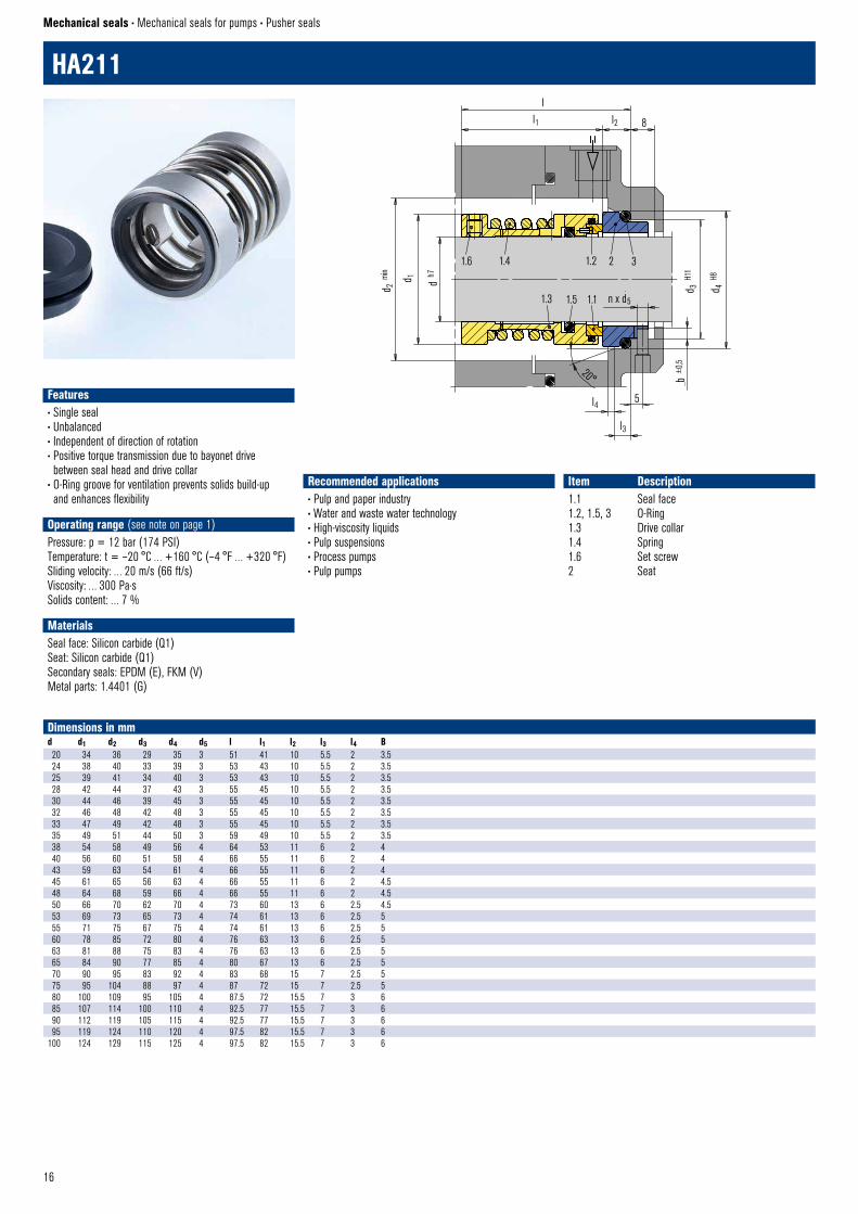
HA211
Mechanical seals • Mechanical seals for pumps • Pusher seals
Dimensions in mmd d1 d2 d3 d4 d5 l l1 l2 l3 l4 B20 34 36 29 35 3 51 41 10 5.5 2 3.524 38 40 33 39 3 53 43 10 5.5 2 3.525 39 41 34 40 3 53 43 10 5.5 2 3.528 42 44 37 43 3 55 45 10 5.5 2 3.530 44 46 39 45 3 55 45 10 5.5 2 3.532 46 48 42 48 3 55 45 10 5.5 2 3.533 47 49 42 48 3 55 45 10 5.5 2 3.535 49 51 44 50 3 59 49 10 5.5 2 3.538 54 58 49 56 4 64 53 11 6 2 440 56 60 51 58 4 66 55 11 6 2 443 59 63 54 61 4 66 55 11 6 2 445 61 65 56 63 4 66 55 11 6 2 4.548 64 68 59 66 4 66 55 11 6 2 4.550 66 70 62 70 4 73 60 13 6 2.5 4.553 69 73 65 73 4 74 61 13 6 2.5 555 71 75 67 75 4 74 61 13 6 2.5 560 78 85 72 80 4 76 63 13 6 2.5 563 81 88 75 83 4 76 63 13 6 2.5 565 84 90 77 85 4 80 67 13 6 2.5 570 90 95 83 92 4 83 68 15 7 2.5 575 95 104 88 97 4 87 72 15 7 2.5 580 100 109 95 105 4 87.5 72 15.5 7 3 685 107 114 100 110 4 92.5 77 15.5 7 3 690 112 119 105 115 4 92.5 77 15.5 7 3 695 119 124 110 120 4 97.5 82 15.5 7 3 6
100 124 129 115 125 4 97.5 82 15.5 7 3 6
Recommended applications• Pulp and paper industry• Water and waste water technology• High-viscosity liquids • Pulp suspensions• Process pumps• Pulp pumps
Item Description1.1 Seal face1.2, 1.5, 3 O-Ring1.3 Drive collar1.4 Spring1.6 Set screw2 Seat
Features• Single seal• Unbalanced• Independent of direction of rotation• Positive torque transmission due to bayonet drive between seal head and drive collar
• O-Ring groove for ventilation prevents solids build-up and enhances flexibility
Operating range (see note on page 1)Pressure: p = 12 bar (174 PSI)Temperature: t = –20 °C … +160 °C (–4 °F … +320 °F)Sliding velocity: … 20 m/s (66 ft/s)Viscosity: … 300 Pa·sSolids content: … 7 %
MaterialsSeal face: Silicon carbide (Q1)Seat: Silicon carbide (Q1)Secondary seals: EPDM (E), FKM (V)Metal parts: 1.4401 (G)
17
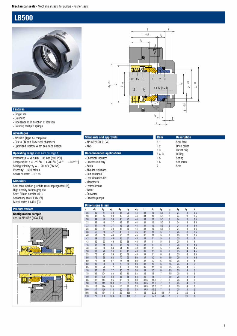
LB500
Mechanical seals • Mechanical seals for pumps • Pusher seals
Standards and approvals• API 682/ISO 21049 • ANSI
Recommended applications• Chemical industry• Process industry• Acids• Alkaline solutions• Salt solutions• Low viscosity oils• Monomers• Hydrocarbons• Water• Seawater• Process pumps
Item Description1.1 Seal face1.2 Drive collar1.3 Thrust ring1.4, 3 O-Ring1.5 Spring1.6 Set screw2 Seat
Dimensions in mmd d1 d2 d3 d4 d5 d6 l l1 l2 l3 l4 l5 b25 39 41 29 35 20 44 34 10 5.5 2 24 3 3.528 42 44 33 39 24 44 34 10 5.5 2 24 3 3.530 44 46 34 40 25 44 34 10 5.5 2 24 3 3.532 46 48 37 43 27 44 34 10 5.5 2 24 3 3.533 47 49 37 43 28 44 34 10 5.5 2 24 3 3.535 49 51 39 45 30 44 34 10 5.5 2 24 3 3.538 55 58 42 48 33 45 35 10 5 2 25 3 3.540 57 60 44 50 35 45 35 10 5 2 25 3 3.542 59 62 49 56 37 48 37 11 5 2 25 4 443 60 63 49 56 38 48 37 11 5 2 25 4 445 62 65 51 58 40 48 37 11 5 2 25 4 4.548 65 68 54 61 43 48 37 11 5 2 25 4 4.550 67 70 56 63 45 48 37 11 6 2 25 4 4.553 70 73 59 66 48 48 37 11 6 2 25 4 4.555 72 75 62 70 50 50 37 13 6 2.5 25 4 4.560 77 85 67 75 55 50 37 13 6 2.5 25 4 563 80 88 70 78 58 50 37 13 6 2.5 25 4 565 82 90 72 80 60 50 37 13 6 2.5 25 4 570 87 95 77 85 65 50 37 13 6 2.5 25 4 575 92 104 83 92 70 53 38 15 7 2.5 25 4 580 97 109 88 97 75 53 38 15 7 2.5 25 4 585 102 114 95 105 80 53 37.5 15.5 7 3 25 4 690 107 119 100 110 85 53 37.5 15.5 7 3 25 4 695 112 124 105 115 90 53 37.5 15.5 7 3 25 4 6
100 117 129 110 120 95 53 37.5 15.5 7 3 25 4 6105 122 134 115 125 100 4 53 37.5 15.5 7 3 25 6110 127 139 120 130 105 4 53 37.5 15.5 7 3 25 6
1.2 1.5 1.3 1.1 2 3
1.6 1.4
8l
l1 ±0,3
l5
l2
b ±
0,5
d 5
d 3
H11
d 4
H8
d 2
min
d h
7
d 1
20°
l4
l3 5
LB500 © EagleBurgmann
n x d6 (n=1)
Configuration sampleacc. to API 682 (1CW-FX)
Product variant
LB500–55 Cartridge © EagleBurgmann
Features• Single seal• Balanced• Independent of direction of rotation• Rotating multiple springs
Advantages• API 682 (Type A) compliant• Fits to EN and ANSI seal chambers• Optimized, narrow width seal face design
Operating range (see note on page 1)Pressure: p = vacuum … 35 bar (508 PSI)Temperature: t = –20 °C … +200 °C (–4 °F … +392 °F)Sliding velocity: vg = … 20 m/s (66 ft/s)Viscosity: … 500 mPa·sSolids content: … 0.5 %
MaterialsSeal face: Carbon graphite resin impregnated (B), High density carbon graphiteSeat: Silicon carbide (Q1)Secondary seals: FKM (V)Metal parts: 1.4401 (G)
18
1) d1 >100 mm: 2 mm x 30°2 d1 >100 mm: 30°3) d1 >100 mm: H74) d1 >100 mm: +0.1
G4
Seat alternatives
30°
l16l15 R
G4 © EagleBurgmann
l12
l14
d 11
+0,1
d 12
H7
Torque transmission
Set screw with cone point © EagleBurgmann
d12 ≥105 mm Torque transmission by 4 set screws with cone point. Offset: 90°
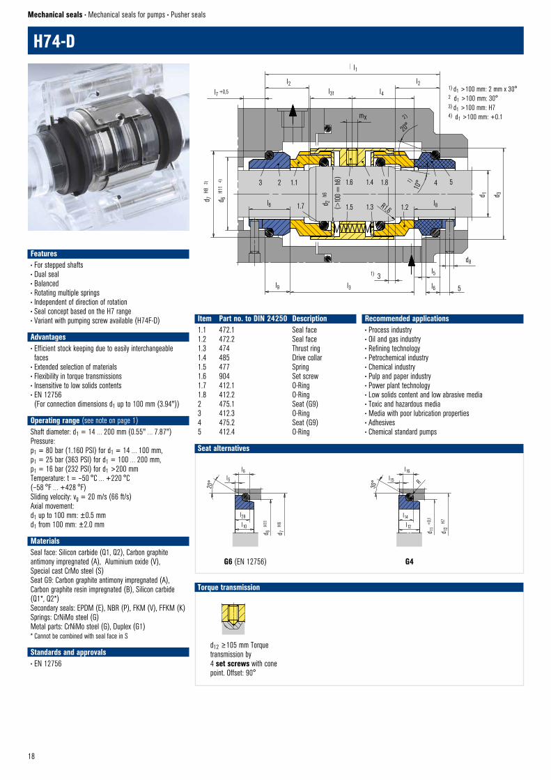
H74-D
Mechanical seals • Mechanical seals for pumps • Pusher seals
Item Part no. to DIN 24250 Description1.1 472.1 Seal face1.2 472.2 Seal face1.3 474 Thrust ring1.4 485 Drive collar1.5 477 Spring1.6 904 Set screw1.7 412.1 O-Ring1.8 412.2 O-Ring2 475.1 Seat (G9)3 412.3 O-Ring4 475.2 Seat (G9)5 412.4 O-Ring
Recommended applications• Process industry• Oil and gas industry• Refining technology• Petrochemical industry• Chemical industry• Pulp and paper industry• Power plant technology• Low solids content and low abrasive media• Toxic and hazardous media• Media with poor lubrication properties• Adhesives• Chemical standard pumps
l28
l10
d7
H8
d6
H11
l6 l5
20°
G6 (M32N4) © EagleBurgmann
l1
l4
l2l31
l2l7 +0,5
mx
20°2)
1)10
°
d 1 d 3
d8
l5
l6 5l331)
l9
d 7 H
8 3)
d 6 H
11 4)
l8 d 2 h
6
( >10
0 =
h8)3 2 1.1 1.6 1.4 1.8
1.5 1.3 R1,6 1.2 l8
4 5
H74 – D © EagleBurgmann
1.7
Features• For stepped shafts• Dual seal• Balanced• Rotating multiple springs• Independent of direction of rotation• Seal concept based on the H7 range• Variant with pumping screw available (H74F-D)
Advantages• Efficient stock keeping due to easily interchangeable faces
• Extended selection of materials• Flexibility in torque transmissions• Insensitive to low solids contents• EN 12756 (For connection dimensions d1 up to 100 mm (3.94"))
Operating range (see note on page 1)Shaft diameter: d1 = 14 … 200 mm (0.55" … 7.87")Pressure: p1 = 80 bar (1.160 PSI) for d1 = 14 … 100 mm,p1 = 25 bar (363 PSI) for d1 = 100 … 200 mm,p1 = 16 bar (232 PSI) for d1 >200 mmTemperature: t = –50 °C … +220 °C (–58 °F … +428 °F)Sliding velocity: vg = 20 m/s (66 ft/s)Axial movement:d1 up to 100 mm: ±0.5 mmd1 from 100 mm: ±2.0 mm
MaterialsSeal face: Silicon carbide (Q1, Q2), Carbon graphite antimony impregnated (A), Aluminium oxide (V), Special cast CrMo steel (S)Seat G9: Carbon graphite antimony impregnated (A), Carbon graphite resin impregnated (B), Silicon carbide (Q1*, Q2*) Secondary seals: EPDM (E), NBR (P), FKM (V), FFKM (K)Springs: CrNiMo steel (G)Metal parts: CrNiMo steel (G), Duplex (G1)* Cannot be combined with seal face in S
Standards and approvals• EN 12756
G6 (EN 12756)
19
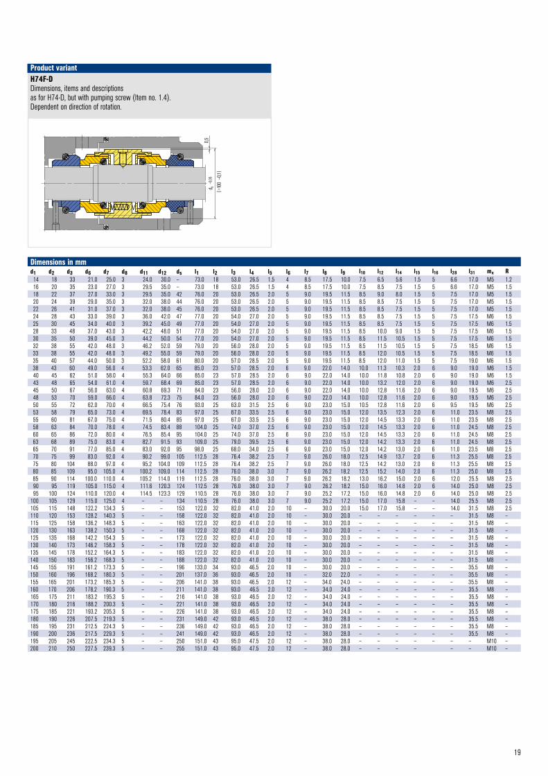
H74F-DDimensions, items and descriptionsas for H74-D, but with pumping screw (Item no. 1.4). Dependent on direction of rotation.
Product variant
Dimensions in mmd1 d2 d3 d6 d7 d8 d11 d12 ds l1 l2 l3 l4 l5 l6 l7 l8 l9 l10 l12 l14 l15 l16 l28 l31 mx R14 18 33 21.0 25.0 3 24.0 30.0 – 73.0 18 53.0 26.5 1.5 4 8.5 17.5 10.0 7.5 6.5 5.6 1.5 5 6.6 17.0 M5 1.216 20 35 23.0 27.0 3 29.5 35.0 – 73.0 18 53.0 26.5 1.5 4 8.5 17.5 10.0 7.5 8.5 7.5 1.5 5 6.6 17.0 M5 1.518 22 37 27.0 33.0 3 29.5 35.0 42 76.0 20 53.0 26.5 2.0 5 9.0 19.5 11.5 8.5 9.0 8.0 1.5 5 7.5 17.0 M5 1.520 24 39 29.0 35.0 3 32.0 38.0 44 76.0 20 53.0 26.5 2.0 5 9.0 19.5 11.5 8.5 8.5 7.5 1.5 5 7.5 17.0 M5 1.522 26 41 31.0 37.0 3 32.0 38.0 45 76.0 20 53.0 26.5 2.0 5 9.0 19.5 11.5 8.5 8.5 7.5 1.5 5 7.5 17.0 M5 1.524 28 43 33.0 39.0 3 36.0 42.0 47 77.0 20 54.0 27.0 2.0 5 9.0 19.5 11.5 8.5 8.5 7.5 1.5 5 7.5 17.5 M6 1.525 30 45 34.0 40.0 3 39.2 45.0 49 77.0 20 54.0 27.0 2.0 5 9.0 19.5 11.5 8.5 8.5 7.5 1.5 5 7.5 17.5 M6 1.528 33 48 37.0 43.0 3 42.2 48.0 51 77.0 20 54.0 27.0 2.0 5 9.0 19.5 11.5 8.5 10.0 9.0 1.5 5 7.5 17.5 M6 1.530 35 50 39.0 45.0 3 44.2 50.0 54 77.0 20 54.0 27.0 2.0 5 9.0 19.5 11.5 8.5 11.5 10.5 1.5 5 7.5 17.5 M6 1.532 38 55 42.0 48.0 3 46.2 52.0 59 79.0 20 56.0 28.0 2.0 5 9.0 19.5 11.5 8.5 11.5 10.5 1.5 5 7.5 18.5 M6 1.533 38 55 42.0 48.0 3 49.2 55.0 59 79.0 20 56.0 28.0 2.0 5 9.0 19.5 11.5 8.5 12.0 10.5 1.5 5 7.5 18.5 M6 1.535 40 57 44.0 50.0 3 52.2 58.0 61 80.0 20 57.0 28.5 2.0 5 9.0 19.5 11.5 8.5 12.0 11.0 1.5 5 7.5 19.0 M6 1.538 43 60 49.0 56.0 4 53.3 62.0 65 85.0 23 57.0 28.5 2.0 6 9.0 22.0 14.0 10.0 11.3 10.3 2.0 6 9.0 19.0 M6 1.540 45 62 51.0 58.0 4 55.3 64.0 66 85.0 23 57.0 28.5 2.0 6 9.0 22.0 14.0 10.0 11.8 10.8 2.0 6 9.0 19.0 M6 1.543 48 65 54.0 61.0 4 59.7 68.4 69 85.0 23 57.0 28.5 2.0 6 9.0 22.0 14.0 10.0 13.2 12.0 2.0 6 9.0 19.0 M6 2.545 50 67 56.0 63.0 4 60.8 69.3 71 84.0 23 56.0 28.0 2.0 6 9.0 22.0 14.0 10.0 12.8 11.6 2.0 6 9.0 19.5 M6 2.548 53 70 59.0 66.0 4 63.8 72.3 75 84.0 23 56.0 28.0 2.0 6 9.0 22.0 14.0 10.0 12.8 11.6 2.0 6 9.0 19.5 M6 2.550 55 72 62.0 70.0 4 66.5 75.4 76 93.0 25 63.0 31.5 2.5 6 9.0 23.0 15.0 10.5 12.8 11.6 2.0 6 9.5 19.5 M6 2.553 58 79 65.0 73.0 4 69.5 78.4 83 97.0 25 67.0 33.5 2.5 6 9.0 23.0 15.0 12.0 13.5 12.3 2.0 6 11.0 23.5 M8 2.555 60 81 67.0 75.0 4 71.5 80.4 85 97.0 25 67.0 33.5 2.5 6 9.0 23.0 15.0 12.0 14.5 13.3 2.0 6 11.0 23.5 M8 2.558 63 84 70.0 78.0 4 74.5 83.4 88 104.0 25 74.0 37.0 2.5 6 9.0 23.0 15.0 12.0 14.5 13.3 2.0 6 11.0 24.5 M8 2.560 65 86 72.0 80.0 4 76.5 85.4 95 104.0 25 74.0 37.0 2.5 6 9.0 23.0 15.0 12.0 14.5 13.3 2.0 6 11.0 24.5 M8 2.563 68 89 75.0 83.0 4 82.7 91.5 93 109.0 25 79.0 39.5 2.5 6 9.0 23.0 15.0 12.0 14.2 13.3 2.0 6 11.0 24.5 M8 2.565 70 91 77.0 85.0 4 83.0 92.0 95 98.0 25 68.0 34.0 2.5 6 9.0 23.0 15.0 12.0 14.2 13.0 2.0 6 11.0 23.5 M8 2.570 75 99 83.0 92.0 4 90.2 99.0 105 112.5 28 76.4 38.2 2.5 7 9.0 26.0 18.0 12.5 14.9 13.7 2.0 6 11.3 25.5 M8 2.575 80 104 88.0 97.0 4 95.2 104.0 109 112.5 28 76.4 38.2 2.5 7 9.0 26.0 18.0 12.5 14.2 13.0 2.0 6 11.3 25.5 M8 2.580 85 109 95.0 105.0 4 100.2 109.0 114 112.5 28 76.0 38.0 3.0 7 9.0 26.2 18.2 12.5 15.2 14.0 2.0 6 11.3 25.0 M8 2.585 90 114 100.0 110.0 4 105.2 114.0 119 112.5 28 76.0 38.0 3.0 7 9.0 26.2 18.2 13.0 16.2 15.0 2.0 6 12.0 25.5 M8 2.590 95 119 105.0 115.0 4 111.6 120.3 124 112.5 28 76.0 38.0 3.0 7 9.0 26.2 18.2 15.0 16.0 14.8 2.0 6 14.0 25.0 M8 2.595 100 124 110.0 120.0 4 114.5 123.3 129 110.5 28 76.0 38.0 3.0 7 9.0 25.2 17.2 15.0 16.0 14.8 2.0 6 14.0 25.0 M8 2.5
100 105 129 115.0 125.0 4 – – 134 110.5 28 76.0 38.0 3.0 7 9.0 25.2 17.2 15.0 17.0 15.8 – – 14.0 25.5 M8 2.5105 115 148 122.2 134.3 5 – – 153 122.0 32 82.0 41.0 2.0 10 – 30.0 20.0 15.0 17.0 15.8 – – 14.0 31.5 M8 2.5110 120 153 128.2 140.3 5 – – 158 122.0 32 82.0 41.0 2.0 10 – 30.0 20.0 – – – – – – 31.5 M8 –115 125 158 136.2 148.3 5 – – 163 122.0 32 82.0 41.0 2.0 10 – 30.0 20.0 – – – – – – 31.5 M8 –120 130 163 138.2 150.3 5 – – 168 122.0 32 82.0 41.0 2.0 10 – 30.0 20.0 – – – – – – 31.5 M8 –125 135 168 142.2 154.3 5 – – 173 122.0 32 82.0 41.0 2.0 10 – 30.0 20.0 – – – – – – 31.5 M8 –130 140 173 146.2 158.3 5 – – 178 122.0 32 82.0 41.0 2.0 10 – 30.0 20.0 – – – – – – 31.5 M8 –135 145 178 152.2 164.3 5 – – 183 122.0 32 82.0 41.0 2.0 10 – 30.0 20.0 – – – – – – 31.5 M8 –140 150 183 156.2 168.3 5 – – 188 122.0 32 82.0 41.0 2.0 10 – 30.0 20.0 – – – – – – 31.5 M8 –145 155 191 161.2 173.3 5 – – 196 133.0 34 93.0 46.5 2.0 10 – 30.0 20.0 – – – – – – 35.5 M8 –150 160 196 168.2 180.3 5 – – 201 137.0 36 93.0 46.5 2.0 10 – 32.0 22.0 – – – – – – 35.5 M8 –155 165 201 173.2 185.3 5 – – 206 141.0 38 93.0 46.5 2.0 12 – 34.0 24.0 – – – – – – 35.5 M8 –160 170 206 178.2 190.3 5 – – 211 141.0 38 93.0 46.5 2.0 12 – 34.0 24.0 – – – – – – 35.5 M8 –165 175 211 183.2 195.3 5 – – 216 141.0 38 93.0 46.5 2.0 12 – 34.0 24.0 – – – – – – 35.5 M8 –170 180 216 188.2 200.3 5 – – 221 141.0 38 93.0 46.5 2.0 12 – 34.0 24.0 – – – – – – 35.5 M8 –175 185 221 193.2 205.3 5 – – 226 141.0 38 93.0 46.5 2.0 12 – 34.0 24.0 – – – – – – 35.5 M8 –180 190 226 207.5 219.3 5 – – 231 149.0 42 93.0 46.5 2.0 12 – 38.0 28.0 – – – – – – 35.5 M8 –185 195 231 212.5 224.3 5 – – 236 149.0 42 93.0 46.5 2.0 12 – 38.0 28.0 – – – – – – 35.5 M8 –190 200 236 217.5 229.3 5 – – 241 149.0 42 93.0 46.5 2.0 12 – 38.0 28.0 – – – – – – 35.5 M8 –195 205 245 222.5 234.3 5 – – 250 151.0 43 95.0 47.5 2.0 12 – 38.0 28.0 – – – – – – – M10 –200 210 250 227.5 239.3 5 – – 255 151.0 43 95.0 47.5 2.0 12 – 38.0 28.0 – – – – – – M10 –
0,5
d s –
0,05
(>10
0 –
0,1)
H74F – D © EahleBurgmann
20
6 3 2 1.1 1.2 1.6
5 4 1.8 1.3 1.4 1.5 1.7
d 4 H
11
d h7d 3
d 1 m
ax
d 2 H
7
l
l2 ±0,3
l3
l1 ±0.05
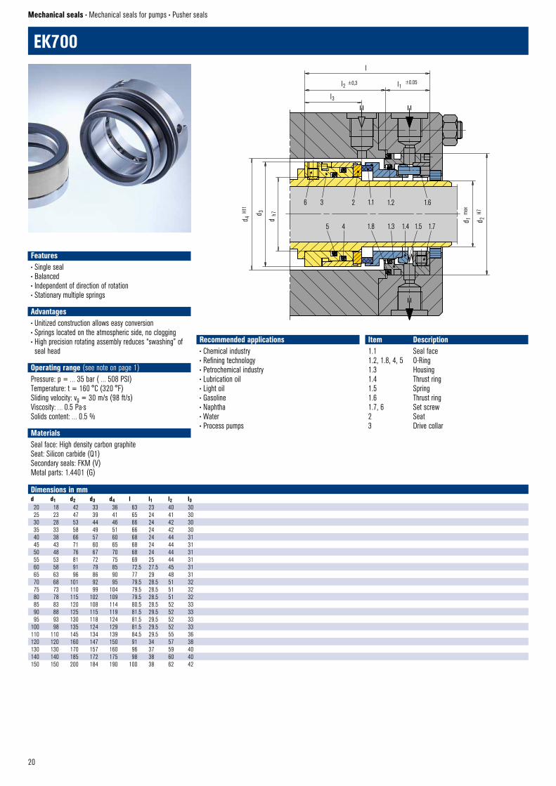
EK700 © EagleBurgmann
EK700
Mechanical seals • Mechanical seals for pumps • Pusher seals
Recommended applications• Chemical industry• Refining technology• Petrochemical industry• Lubrication oil• Light oil • Gasoline • Naphtha • Water• Process pumps
Item Description1.1 Seal face1.2, 1.8, 4, 5 O-Ring1.3 Housing1.4 Thrust ring1.5 Spring1.6 Thrust ring1.7, 6 Set screw2 Seat3 Drive collar
Dimensions in mmd d1 d2 d3 d4 l l1 l2 l320 18 42 33 36 63 23 40 3025 23 47 39 41 65 24 41 3030 28 53 44 46 66 24 42 3035 33 58 49 51 66 24 42 3040 38 66 57 60 68 24 44 3145 43 71 60 65 68 24 44 3150 48 76 67 70 68 24 44 3155 53 81 72 75 69 25 44 3160 58 91 79 85 72.5 27.5 45 3165 63 96 86 90 77 29 48 3170 68 101 92 95 79.5 28.5 51 3275 73 110 99 104 79.5 28.5 51 3280 78 115 102 109 79.5 28.5 51 3285 83 120 108 114 80.5 28.5 52 3390 88 125 115 119 81.5 29.5 52 3395 93 130 118 124 81.5 29.5 52 33
100 98 135 124 129 81.5 29.5 52 33110 110 145 134 139 84.5 29.5 55 36120 120 160 147 150 91 34 57 38130 130 170 157 160 96 37 59 40140 140 185 172 175 98 38 60 40150 150 200 184 190 100 38 62 42
Features• Single seal• Balanced• Independent of direction of rotation• Stationary multiple springs
Advantages• Unitized construction allows easy conversion• Springs located on the atmospheric side, no clogging• High precision rotating assembly reduces “swashing” of seal head
Operating range (see note on page 1)Pressure: p = … 35 bar ( … 508 PSI)Temperature: t = 160 °C (320 °F)Sliding velocity: vg = 30 m/s (98 ft/s)Viscosity: … 0.5 Pa·sSolids content: … 0.5 %
MaterialsSeal face: High density carbon graphiteSeat: Silicon carbide (Q1)Secondary seals: FKM (V)Metal parts: 1.4401 (G)
21
6 2.3 2.1 1.1 1.3 1.8
5 4 2.2 1.2 1.4 1.6 1.5 1.7
d 2
d 1
dh7H1
1
d 2 d 3
H11
H7
l1
l ±0,3
20 ±0,05
2
10
L9UC © EagleBurgmann
3
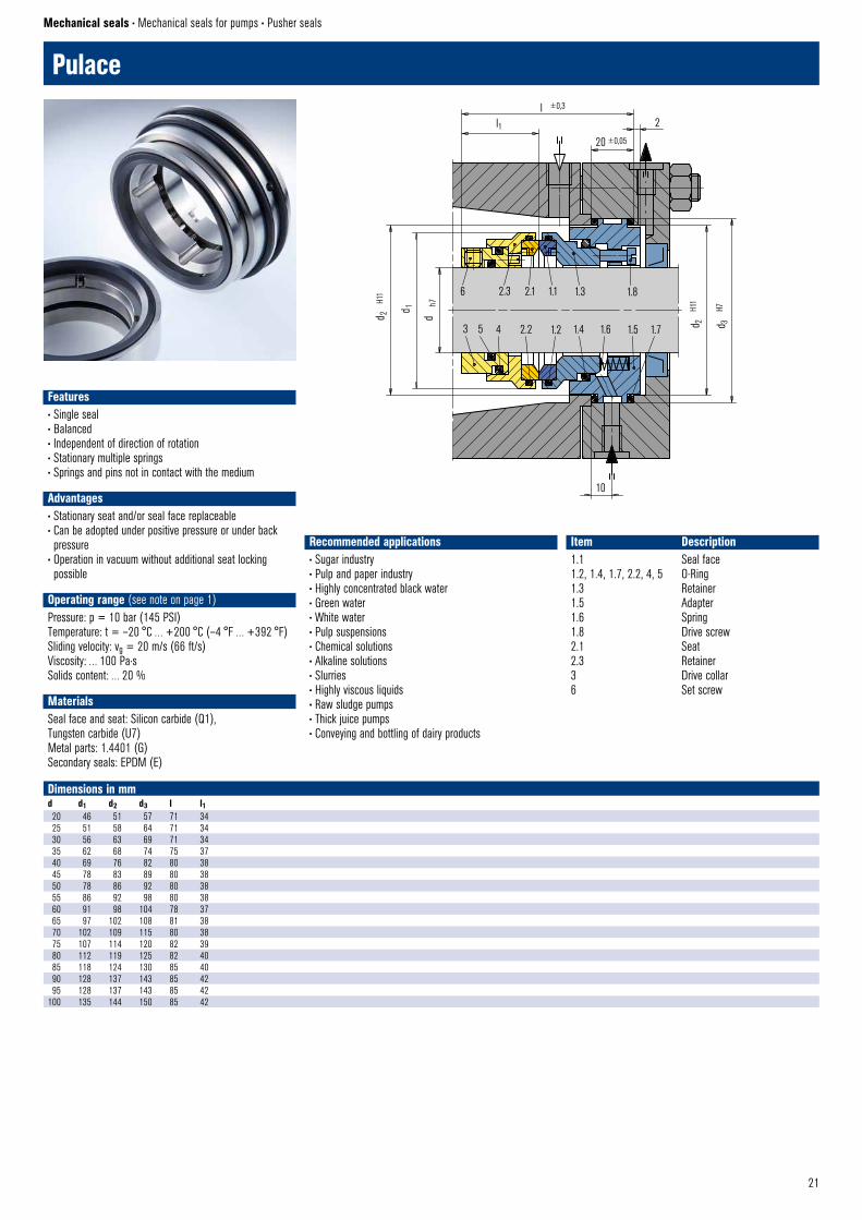
Pulace
Mechanical seals • Mechanical seals for pumps • Pusher seals
Recommended applications• Sugar industry• Pulp and paper industry• Highly concentrated black water • Green water • White water• Pulp suspensions• Chemical solutions• Alkaline solutions • Slurries • Highly viscous liquids• Raw sludge pumps• Thick juice pumps• Conveying and bottling of dairy products
Item Description1.1 Seal face1.2, 1.4, 1.7, 2.2, 4, 5 O-Ring1.3 Retainer1.5 Adapter1.6 Spring1.8 Drive screw2.1 Seat2.3 Retainer3 Drive collar6 Set screw
Dimensions in mmd d1 d2 d3 l l120 46 51 57 71 3425 51 58 64 71 3430 56 63 69 71 3435 62 68 74 75 3740 69 76 82 80 3845 78 83 89 80 3850 78 86 92 80 3855 86 92 98 80 3860 91 98 104 78 3765 97 102 108 81 3870 102 109 115 80 3875 107 114 120 82 3980 112 119 125 82 4085 118 124 130 85 4090 128 137 143 85 4295 128 137 143 85 42
100 135 144 150 85 42
Features• Single seal• Balanced• Independent of direction of rotation• Stationary multiple springs• Springs and pins not in contact with the medium
Advantages• Stationary seat and/or seal face replaceable• Can be adopted under positive pressure or under back pressure
• Operation in vacuum without additional seat locking possible
Operating range (see note on page 1)Pressure: p = 10 bar (145 PSI)Temperature: t = –20 °C … +200 °C (–4 °F … +392 °F)Sliding velocity: vg = 20 m/s (66 ft/s)Viscosity: … 100 Pa·sSolids content: … 20 %
MaterialsSeal face and seat: Silicon carbide (Q1), Tungsten carbide (U7)Metal parts: 1.4401 (G)Secondary seals: EPDM (E)
22
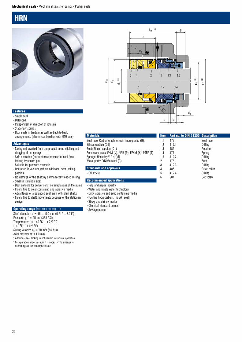
HRN
Mechanical seals • Mechanical seals for pumps • Pusher seals
MaterialsSeal face: Carbon graphite resin impregnated (B), Silicon carbide (Q1)Seat: Silicon carbide (Q1)Secondary seals: FKM (V), NBR (P), FFKM (K), PTFE (T)Springs: Hastelloy® C-4 (M)Metal parts: CrNiMo steel (G)
Standards and approvals• EN 12756
Recommended applications• Pulp and paper industry• Water and waste water technology• Dirty, abrasive and solid containing media• Fugitive hydrocarbons (no API seal!)• Sticky and stringy media• Chemical standard pumps• Sewage pumps
Item Part no. to DIN 24250 Description1.1 472 Seal face1.2 412.1 O-Ring1.3 485 Retainer1.4 477 Spring1.5 412.2 O-Ring2 475 Seat3 412.3 O-Ring4 485 Drive collar5 412.4 O-Ring6 904 Set screw
6 4 2 1.1 1.3 1.5
5 3 1.2 1.4
d 6
H11
d 7
H8
d 1
h6
d 10
d 3
9l1k ±1
l3
fmx
20°
l6l5 5
d8
HRN © EagleBurgmann
Features• Single seal• Balanced• Independent of direction of rotation• Stationary springs • Dual seals in tandem as well as back-to-back arrangements (also in combination with H10 seal)
Advantages• Spring unit averted from the product so no sticking and clogging of the springs
• Safe operation (no fractures) because of seal face locking by square pin
• Suitable for pressure reversals• Operation in vacuum without additional seat locking possible
• No damage of the shaft by a dynamically loaded O-Ring• Small installation sizes• Best suitable for conversions, no adaptations of the pump• Insensitive to solid containing and abrasive media• Advantages of a balanced seal even with plain shafts• Insensitive to shaft movements because of the stationary design
Operating range (see note on page 1)Shaft diameter: d = 18 … 100 mm (0.71" … 3.94")Pressure: p1* = 25 bar (363 PSI)Temperature: t = –40 °C … +220 °C (–40 °F … +428 °F)Sliding velocity: vg = 20 m/s (66 ft/s)Axial movement: ±1.0 mm* Additional seat locking is not needed in vacuum operation. * For operation under vacuum it is necessary to arrange for
quenching on the atmosphere side.
23
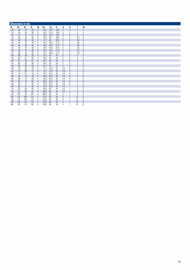
Dimensions in mmd1 d3 d6 d7 d8 d10 I1k I3 I5 I6 f mx 18 33 27 33 3 34.7 37.5 19.5 2 5 3 420 35 29 35 3 36.7 37.5 19.5 2 5 3 422 37 31 37 3 38.7 37.5 19.5 2 5 3 424 39 33 39 3 40.7 40 20.5 2 5 3.5 525 40 34 40 3 41.7 40 20.5 2 5 3.5 528 43 37 43 3 44.7 42.5 21.5 2 5 3.5 530 45 39 45 3 46.7 42.5 21.5 2 5 3.5 532 48 42 48 3 49.7 42.5 21.5 2 5 3.5 533 48 42 48 3 49.7 42.5 21.5 2 5 3.5 535 50 44 50 3 51.7 42.5 21.5 2 5 3.5 538 56 49 56 4 57.7 45 24 2 6 4 640 58 51 58 4 59.7 45 24 2 6 4 643 61 54 61 4 62.7 45 24 2 6 4 645 63 56 63 4 64.7 45 24 2 6 4 648 66 59 66 4 67.7 45 24 2 6 4 650 70 62 70 4 71.7 47.5 25 2.5 6 4 653 73 65 73 4 74.7 47.5 25 2.5 6 4 655 75 67 75 4 76.7 47.5 25 2.5 6 4 658 78 70 78 4 80.5 52.5 28 2.5 6 4 660 80 72 80 4 82.5 52.5 28 2.5 6 4 663 83 75 83 4 85.5 52.5 28 2.5 6 4 665 85 77 85 4 87.5 52.5 28 2.5 6 4 668 90 81 90 4 92.5 52.5 28 2.5 7 4 670 92 83 92 4 94.5 60 34 2.5 7 6 875 97 88 97 4 100.5 60 34 2.5 7 6 880 105 95 105 4 108.5 60 34 3 7 6 885 110 100 110 4 113.5 60 34 3 7 6 890 115 105 115 4 118.5 65 39 3 7 10 895 120 110 120 4 123.5 65 39 3 7 10 8
100 125 115 125 4 128.5 65 39 3 7 10 8
24
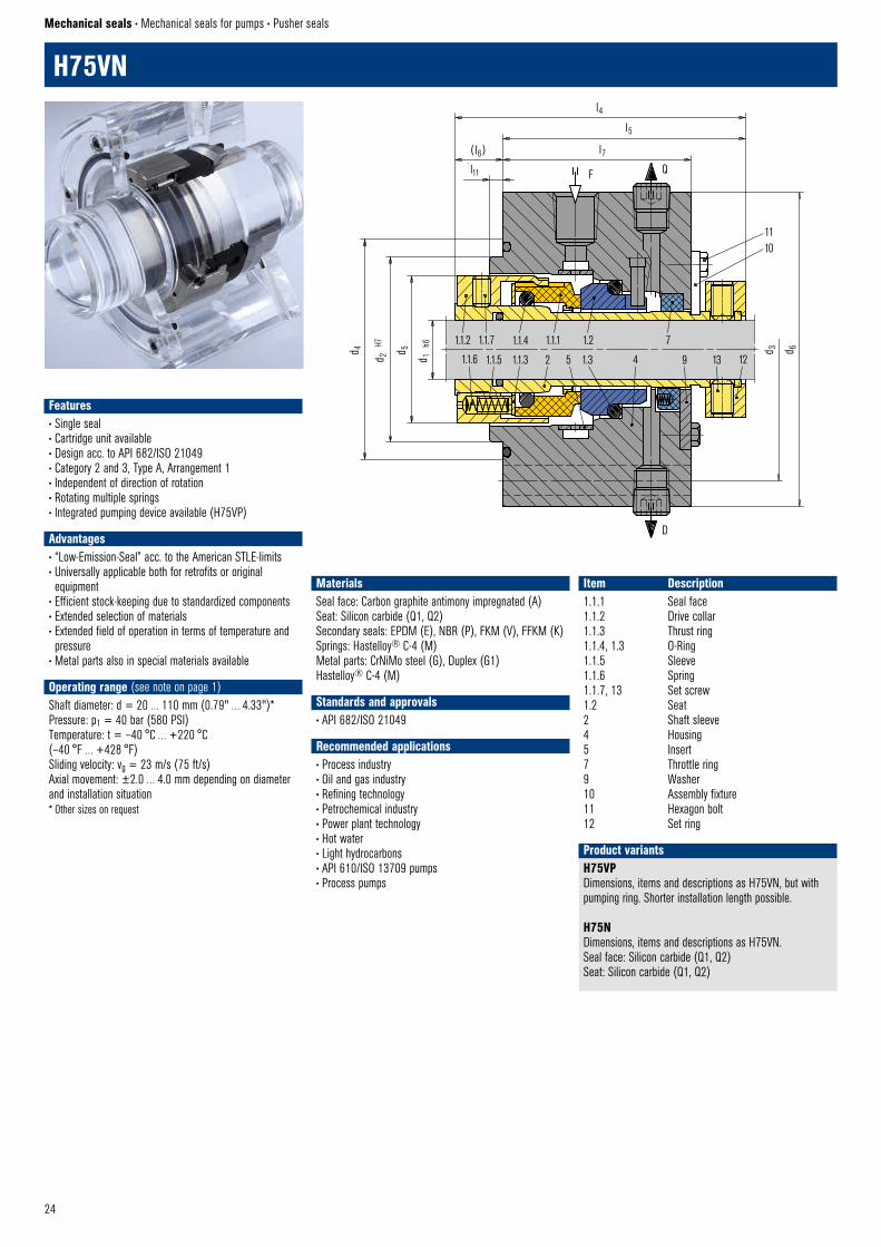
H75VN
Mechanical seals • Mechanical seals for pumps • Pusher seals
Item Description1.1.1 Seal face1.1.2 Drive collar1.1.3 Thrust ring1.1.4, 1.3 O-Ring1.1.5 Sleeve1.1.6 Spring1.1.7, 13 Set screw1.2 Seat2 Shaft sleeve4 Housing5 Insert7 Throttle ring9 Washer10 Assembly fixture11 Hexagon bolt12 Set ring
H75VPDimensions, items and descriptions as H75VN, but with pumping ring. Shorter installation length possible.
H75NDimensions, items and descriptions as H75VN. Seal face: Silicon carbide (Q1, Q2)Seat: Silicon carbide (Q1, Q2)
Product variants
MaterialsSeal face: Carbon graphite antimony impregnated (A) Seat: Silicon carbide (Q1, Q2)Secondary seals: EPDM (E), NBR (P), FKM (V), FFKM (K)Springs: Hastelloy® C-4 (M)Metal parts: CrNiMo steel (G), Duplex (G1) Hastelloy® C-4 (M)
Standards and approvals• API 682/ISO 21049
Recommended applications• Process industry• Oil and gas industry• Refining technology• Petrochemical industry• Power plant technology• Hot water• Light hydrocarbons• API 610/ISO 13709 pumps• Process pumps
l4
l5
l7l11
( l6)
F Q
d 4
d 2
H7
d 1
h6
d 5
d 3 d 6
1.1.2 1.1.7 1.1.4 1.1.1 1.2 7
1.1.3 2 1.3 4
D
API–H75VN © EagleBurgmann
1110
9 13 121.1.6 1.1.5 5
Features• Single seal• Cartridge unit available• Design acc. to API 682/ISO 21049• Category 2 and 3, Type A, Arrangement 1• Independent of direction of rotation• Rotating multiple springs• Integrated pumping device available (H75VP)
Advantages• “Low-Emission-Seal” acc. to the American STLE-limits• Universally applicable both for retrofits or original equipment
• Efficient stock-keeping due to standardized components• Extended selection of materials• Extended field of operation in terms of temperature and pressure
• Metal parts also in special materials available
Operating range (see note on page 1)Shaft diameter: d = 20 … 110 mm (0.79" … 4.33")*Pressure: p1 = 40 bar (580 PSI)Temperature: t = –40 °C … +220 °C (–40 °F … +428 °F)Sliding velocity: vg = 23 m/s (75 ft/s)Axial movement: ±2.0 … 4.0 mm depending on diameter and installation situation* Other sizes on request
25
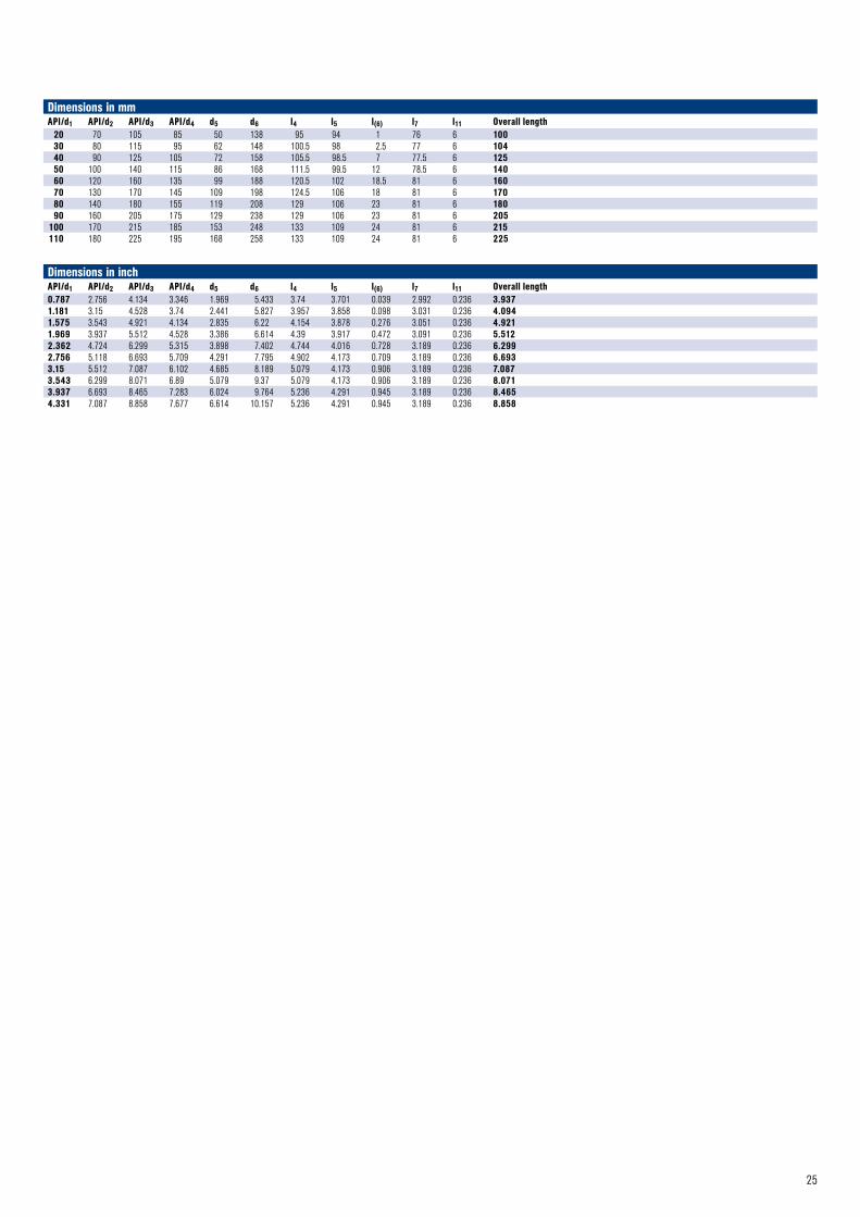
Dimensions in mmAPI/d1 API/d2 API/d3 API/d4 d5 d6 l4 l5 l(6) l7 l11 Overall length
20 70 105 85 50 138 95 94 1 76 6 10030 80 115 95 62 148 100.5 98 2.5 77 6 10440 90 125 105 72 158 105.5 98.5 7 77.5 6 12550 100 140 115 86 168 111.5 99.5 12 78.5 6 14060 120 160 135 99 188 120.5 102 18.5 81 6 16070 130 170 145 109 198 124.5 106 18 81 6 17080 140 180 155 119 208 129 106 23 81 6 18090 160 205 175 129 238 129 106 23 81 6 205
100 170 215 185 153 248 133 109 24 81 6 215110 180 225 195 168 258 133 109 24 81 6 225
Dimensions in inchAPI/d1 API/d2 API/d3 API/d4 d5 d6 l4 l5 l(6) l7 l11 Overall length 0.787 2.756 4.134 3.346 1.969 5.433 3.74 3.701 0.039 2.992 0.236 3.9371.181 3.15 4.528 3.74 2.441 5.827 3.957 3.858 0.098 3.031 0.236 4.0941.575 3.543 4.921 4.134 2.835 6.22 4.154 3.878 0.276 3.051 0.236 4.9211.969 3.937 5.512 4.528 3.386 6.614 4.39 3.917 0.472 3.091 0.236 5.5122.362 4.724 6.299 5.315 3.898 7.402 4.744 4.016 0.728 3.189 0.236 6.2992.756 5.118 6.693 5.709 4.291 7.795 4.902 4.173 0.709 3.189 0.236 6.6933.15 5.512 7.087 6.102 4.685 8.189 5.079 4.173 0.906 3.189 0.236 7.0873.543 6.299 8.071 6.89 5.079 9.37 5.079 4.173 0.906 3.189 0.236 8.0713.937 6.693 8.465 7.283 6.024 9.764 5.236 4.291 0.945 3.189 0.236 8.4654.331 7.087 8.858 7.677 6.614 10.157 5.236 4.291 0.945 3.189 0.236 8.858
26
l4l6 l5
l7
LBO
l10
d 4
d 2
H7
d 5
d 1
h6
3 1.1.6 1.3
4 2.1.1 2.2
11
d 3 d 6
LBI
API–H75VK–D © EagleBurgmann
6
1.1.7 1.1.2 1.1.3 1.1.1 1.2
1.1.5 1.1.4 8 2.1.6 2.1.5 2.1.3 2.3
12 16 152.1.42.1.29
1413
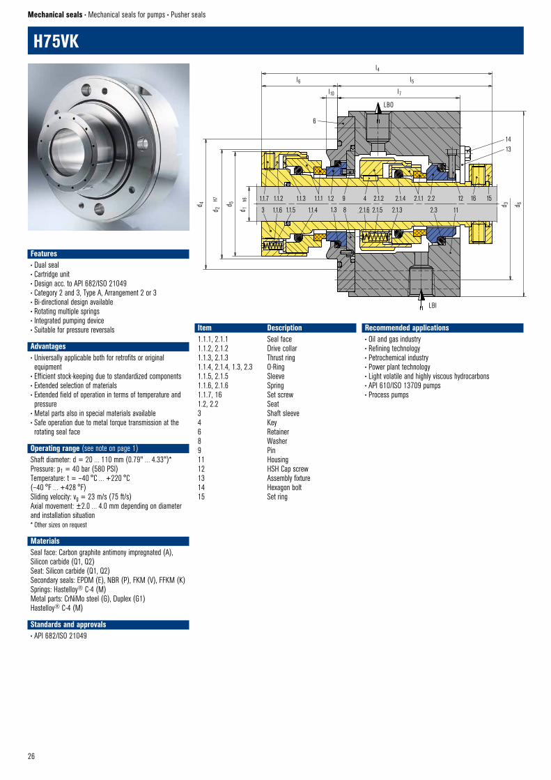
H75VK
Mechanical seals • Mechanical seals for pumps • Pusher seals
Recommended applications• Oil and gas industry• Refining technology• Petrochemical industry• Power plant technology• Light volatile and highly viscous hydrocarbons• API 610/ISO 13709 pumps• Process pumps
Item Description1.1.1, 2.1.1 Seal face1.1.2, 2.1.2 Drive collar1.1.3, 2.1.3 Thrust ring1.1.4, 2.1.4, 1.3, 2.3 O-Ring1.1.5, 2.1.5 Sleeve1.1.6, 2.1.6 Spring1.1.7, 16 Set screw1.2, 2.2 Seat3 Shaft sleeve4 Key6 Retainer8 Washer9 Pin11 Housing12 HSH Cap screw13 Assembly fixture14 Hexagon bolt15 Set ring
Features• Dual seal• Cartridge unit• Design acc. to API 682/ISO 21049• Category 2 and 3, Type A, Arrangement 2 or 3• Bi-directional design available• Rotating multiple springs• Integrated pumping device • Suitable for pressure reversals
Advantages• Universally applicable both for retrofits or original equipment
• Efficient stock-keeping due to standardized components• Extended selection of materials• Extended field of operation in terms of temperature and pressure
• Metal parts also in special materials available• Safe operation due to metal torque transmission at the rotating seal face
Operating range (see note on page 1)Shaft diameter: d = 20 … 110 mm (0.79" … 4.33")*Pressure: p1 = 40 bar (580 PSI)Temperature: t = –40 °C … +220 °C (–40 °F … +428 °F)Sliding velocity: vg = 23 m/s (75 ft/s)Axial movement: ±2.0 … 4.0 mm depending on diameter and installation situation* Other sizes on request
MaterialsSeal face: Carbon graphite antimony impregnated (A), Silicon carbide (Q1, Q2)Seat: Silicon carbide (Q1, Q2)Secondary seals: EPDM (E), NBR (P), FKM (V), FFKM (K)Springs: Hastelloy® C-4 (M)Metal parts: CrNiMo steel (G), Duplex (G1) Hastelloy® C-4 (M)
Standards and approvals• API 682/ISO 21049

27
H75VKP-DDual seal in back-to-back arrangement. Suitable for API 610 table 6 seal chambers.
Product variant
Dimensions in mmAPI/d1 API/d2 API/d3 API/d4 d5 d6 l4 l5 l6 l7 l10 Axial movement
20 70 105 85 60 129 144 97 47 81 6 ±2.0030 80 115 95 70 139 145.5 96 49.5 77.5 8 ±2.0040 90 125 105 82 149 146.5 96.5 50 78 8 ±2.0050 100 140 115 94 168 158 106.5 51.5 88 10.5 ±2.00*60 120 160 135 114 188 165 107.5 57.5 90.2 4.5 ±2.00*70 130 170 145 124 198 170 107.5 62.5 85 10 ±2.00*80 140 180 155 134 208 175 107.5 67.5 85 12.5 ±2.00*90 160 205 175 146 238 178.8 116.9 61.9 94.4 6.9 ±3.00
100 170 215 185 163 248 185 117.5 67.5 92 11.5 ±2.00*110 180 225 195 173 258 188 116.5 71.5 91 15.5 ±3.00
* For larger installation space an axial movement of ±3.0 mm is possible
Dimensions in inchAPI/d1 API/d2 API/d3 API/d4 d5 d6 l4 l5 l6 l7 l10 Axial movement0.787 2.756 4.134 3.346 2.362 5.079 5.669 3.819 1.85 3.189 0.236 ±0.0791.181 3.15 4.528 3.74 2.756 5.472 5.728 3.780 1.949 3.051 0.315 ±0.0791.575 3.543 4.921 4.134 3.228 5.866 5.768 3.799 1.969 3.071 0.315 ±0.0791.969 3.937 5.512 4.528 3.701 6.614 6.22 4.193 2.028 3.465 0.413 ±0.079*2.362 4.724 6.299 5.315 4.488 7.402 6.496 4.232 2.264 3.551 0.177 ±0.079*2.756 5.118 6.693 5.709 4.882 7.795 6.693 4.232 2.461 3.346 0.394 ±0.079*3.15 5.512 7.087 6.102 5.276 8.189 6.89 4.232 2.657 3.346 0.492 ±0.079*3.543 6.299 8.071 6.89 5.748 9.37 7.039 4.602 2.437 3.717 0.272 ±0.1183.937 6.693 8.465 7.283 6.417 9.764 7.283 4.626 2.657 3.622 0.453 ±0.079*4.331 7.087 8.858 7.677 6.811 10.157 7.402 4.587 2.815 3.583 0.61 ±0.118
* For larger installation space an axial movement of 0.118" is possible
LBO
LBI
API–H75VKP–D © EagleBurgmann
d 4
d 4
d 2
H7
d 1
h6
d 3 d 6
3 1 3 6 7 3 1 2 3
2 5 4 4 5 8 9

28
HJ927GN HJ977GN HJ4 ... (example)
HJ92N
Mechanical seals • Mechanical seals for pumps • Pusher seals
Recommended applications• Pharmaceutical industry• Power plant technology• Pulp and paper industry• Water and waste water technology• Mining industry• Food and beverage industry• Sugar industry• Contaminated, abrasive and solids containing media• Thick juice (70 ... 75 % sugar content)• Raw sludge, sewage slurries• Raw sludge pumps• Thick juice pumps• Conveying and bottling of dairy products
Item Part no. to DIN 24250 Description1.1 472/473 Seal face1.2 485 Drive collar1.3 412.2 O-Ring1.4 412.1 O-Ring1.5 477 Spring1.6 904 Set screw2 475 Seat (G16)3 412.3 O-Ring
HJ927GNItems and description as HJ92N.Seal face: Carbon graphite antimony impregnated (A), Carbon graphite resin impregnated (B)Seat G46: Silicon carbide (Q12)Installations length l11 (= l3 + l39) is longer than l1k.
HJ97GN5Items and description as HJ92N.Seal face: Silicon carbide (Q12)Seat G16: Silicon carbide (Q1)Installations length l12 (= l13 + l19) is shorter than l1k.
HJ977GNItems and description as HJ92N.Seal face: Silicon carbide (Q12)Seat G46: Silicon carbide (Q12)Installation length l1kOperating range: Temperature: t = –20 °C … +180 °C (–4 °F … +356 °F)Sliding velocity: vg = 10 m/s (33 ft/s)
HJ4...Mechanical seals with product-protected multiple springs, for high pressure applications.Pressure: p = max. 50 bar (725 PSI)Shaft diameter: d1 >100 mm (3,94") Smaller diameters and higher pressure on request.
Product variants
1.6 1.4 1.5 1.1 2 3
1.2 1.3 l18
mx
l1k
l3 l7 +0,5
l19f
d 3 d m
d 1 h6
d 6 H1
1
d 7 H8
d8
l5 l6 5
20°
HJ92N © EagleBurgmann
l39
l38
l3
HJ927GN © EagleBurgmann
l11
l13 l39
l38
HJ977GN © EagleBurgmann
l1k
1.6 1.4 321.1
1.2 1.3 1.5
HJ4 © EagleBurgmann
Features• For unstepped shafts• Single seal• Balanced• Independent of direction of rotation• Encapsulated rotating spring
Advantages• Especially designed for solids containing and highly viscous media
• Springs are protected from the product• Rugged and reliable design• No damage of the shaft by dynamically loaded O-Ring• Universal application• Variant for operation under vacuum available• Variant for sterile operation available
Operating range (see note on page 1)Shaft diameter: d1 = 18 … 100 mm (0.71" … 4")Pressure: p1* = 0.8 abs … 25 bar (12 abs. … 363 PSI)Temperature: t = –50 °C … +220 °C (–58 °F … +430 °F)Sliding velocity: vg = 20 m/s (66 ft/s)Axial movement: ±0.5 mm.* An integral stationary seat lock is not needed within the
permissible low pressure range. For prolonged operation under vacuum it is necessary to arrange for quenching on the atmospheric side.
MaterialsSeal face: Carbon graphite antimony impregnated (A), Carbon graphite resin impregnated (B)Seat G16: Silicon carbide (Q1)
Standards and approvals• EN 12756
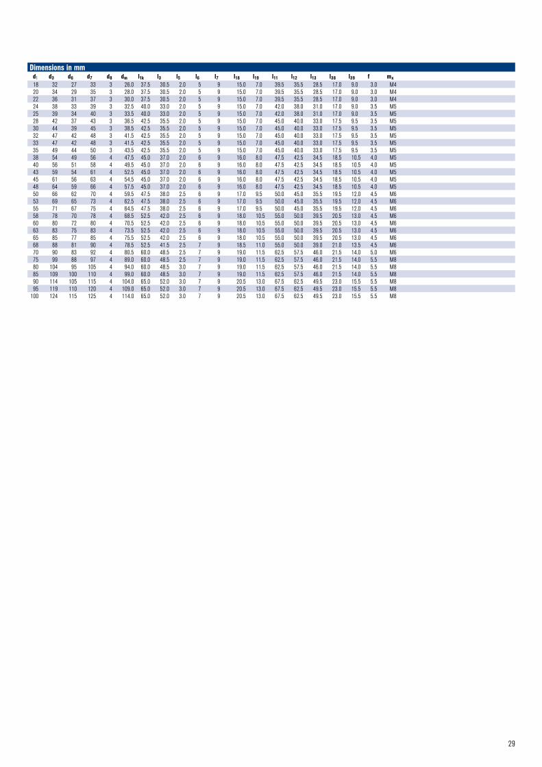
29
Dimensions in mmd1 d3 d6 d7 d8 dm l1k l3 l5 l6 l7 l18 l19 l11 l12 l13 l38 l39 f mx18 32 27 33 3 26.0 37.5 30.5 2.0 5 9 15.0 7.0 39.5 35.5 28.5 17.0 9.0 3.0 M420 34 29 35 3 28.0 37.5 30.5 2.0 5 9 15.0 7.0 39.5 35.5 28.5 17.0 9.0 3.0 M422 36 31 37 3 30.0 37.5 30.5 2.0 5 9 15.0 7.0 39.5 35.5 28.5 17.0 9.0 3.0 M424 38 33 39 3 32.5 40.0 33.0 2.0 5 9 15.0 7.0 42.0 38.0 31.0 17.0 9.0 3.5 M525 39 34 40 3 33.5 40.0 33.0 2.0 5 9 15.0 7.0 42.0 38.0 31.0 17.0 9.0 3.5 M528 42 37 43 3 36.5 42.5 35.5 2.0 5 9 15.0 7.0 45.0 40.0 33.0 17.5 9.5 3.5 M530 44 39 45 3 38.5 42.5 35.5 2.0 5 9 15.0 7.0 45.0 40.0 33.0 17.5 9.5 3.5 M532 47 42 48 3 41.5 42.5 35.5 2.0 5 9 15.0 7.0 45.0 40.0 33.0 17.5 9.5 3.5 M533 47 42 48 3 41.5 42.5 35.5 2.0 5 9 15.0 7.0 45.0 40.0 33.0 17.5 9.5 3.5 M535 49 44 50 3 43.5 42.5 35.5 2.0 5 9 15.0 7.0 45.0 40.0 33.0 17.5 9.5 3.5 M538 54 49 56 4 47.5 45.0 37.0 2.0 6 9 16.0 8.0 47.5 42.5 34.5 18.5 10.5 4.0 M540 56 51 58 4 49.5 45.0 37.0 2.0 6 9 16.0 8.0 47.5 42.5 34.5 18.5 10.5 4.0 M543 59 54 61 4 52.5 45.0 37.0 2.0 6 9 16.0 8.0 47.5 42.5 34.5 18.5 10.5 4.0 M545 61 56 63 4 54.5 45.0 37.0 2.0 6 9 16.0 8.0 47.5 42.5 34.5 18.5 10.5 4.0 M548 64 59 66 4 57.5 45.0 37.0 2.0 6 9 16.0 8.0 47.5 42.5 34.5 18.5 10.5 4.0 M550 66 62 70 4 59.5 47.5 38.0 2.5 6 9 17.0 9.5 50.0 45.0 35.5 19.5 12.0 4.5 M653 69 65 73 4 62.5 47.5 38.0 2.5 6 9 17.0 9.5 50.0 45.0 35.5 19.5 12.0 4.5 M655 71 67 75 4 64.5 47.5 38.0 2.5 6 9 17.0 9.5 50.0 45.0 35.5 19.5 12.0 4.5 M658 78 70 78 4 68.5 52.5 42.0 2.5 6 9 18.0 10.5 55.0 50.0 39.5 20.5 13.0 4.5 M660 80 72 80 4 70.5 52.5 42.0 2.5 6 9 18.0 10.5 55.0 50.0 39.5 20.5 13.0 4.5 M663 83 75 83 4 73.5 52.5 42.0 2.5 6 9 18.0 10.5 55.0 50.0 39.5 20.5 13.0 4.5 M665 85 77 85 4 75.5 52.5 42.0 2.5 6 9 18.0 10.5 55.0 50.0 39.5 20.5 13.0 4.5 M668 88 81 90 4 78.5 52.5 41.5 2.5 7 9 18.5 11.0 55.0 50.0 39.0 21.0 13.5 4.5 M670 90 83 92 4 80.5 60.0 48.5 2.5 7 9 19.0 11.5 62.5 57.5 46.0 21.5 14.0 5.0 M675 99 88 97 4 89.0 60.0 48.5 2.5 7 9 19.0 11.5 62.5 57.5 46.0 21.5 14.0 5.5 M880 104 95 105 4 94.0 60.0 48.5 3.0 7 9 19.0 11.5 62.5 57.5 46.0 21.5 14.0 5.5 M885 109 100 110 4 99.0 60.0 48.5 3.0 7 9 19.0 11.5 62.5 57.5 46.0 21.5 14.0 5.5 M890 114 105 115 4 104.0 65.0 52.0 3.0 7 9 20.5 13.0 67.5 62.5 49.5 23.0 15.5 5.5 M895 119 110 120 4 109.0 65.0 52.0 3.0 7 9 20.5 13.0 67.5 62.5 49.5 23.0 15.5 5.5 M8
100 124 115 125 4 114.0 65.0 52.0 3.0 7 9 20.5 13.0 67.5 62.5 49.5 23.0 15.5 5.5 M8
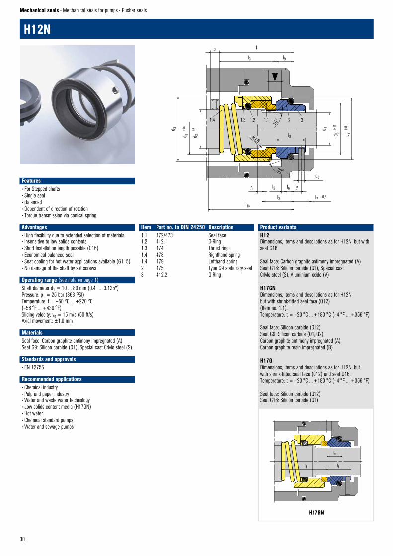
30
l1
l3 l9
d 1
d 6
H11
d 7
H8
d b
min
d 2
h6d 3
l8
1.4 1.3 1.2 1.1 2 3
10°
R1,6
b
HN12 © EagleBurgmann
l1N
l2
l53 5
d8
l6
l7 +0,5
20°
H17GN © EagleBurgmann
l3 l8
l9
H17GN
H12N
Mechanical seals • Mechanical seals for pumps • Pusher seals
Item Part no. to DIN 24250 Description1.1 472/473 Seal face1.2 412.1 O-Ring1.3 474 Thrust ring1.4 478 Righthand spring1.4 479 Lefthand spring2 475 Type G9 stationary seat3 412.2 O-Ring
H12Dimensions, items and descriptions as for H12N, but with seat G16.
Seal face: Carbon graphite antimony impregnated (A) Seat G16: Silicon carbide (Q1), Special cast CrMo steel (S), Aluminium oxide (V)
H17GNDimensions, items and descriptions as for H12N, but with shrink-fitted seal face (Q12) (Item no. 1.1).Temperature: t = –20 °C … +180 °C (–4 °F … +356 °F)
Seal face: Silicon carbide (Q12)Seat G9: Silicon carbide (Q1, Q2), Carbon graphite antimony impregnated (A), Carbon graphite resin impregnated (B)
H17GDimensions, items and descriptions as for H12N, but with shrink-fitted seal face (Q12) and seat G16.Temperature: t = –20 °C … +180 °C (–4 °F … +356 °F)
Seal face: Silicon carbide (Q12)Seat G16: Silicon carbide (Q1)
Product variants
Features• For Stepped shafts• Single seal• Balanced• Dependent of direction of rotation• Torque transmission via conical spring
Advantages• High flexibility due to extended selection of materials• Insensitive to low solids contents• Short Installation length possible (G16)• Economical balanced seal• Seat cooling for hot water applications available (G115)• No damage of the shaft by set screws
Operating range (see note on page 1)Shaft diameter d1 = 10 … 80 mm (0.4" … 3.125")Pressure: p1 = 25 bar (363 PSI)Temperature: t = –50 °C … +220 °C (–58 °F … +430 °F)Sliding velocity: vg = 15 m/s (50 ft/s)Axial movement: ±1.0 mm
MaterialsSeal face: Carbon graphite antimony impregnated (A) Seat G9: Silicon carbide (Q1), Special cast CrMo steel (S)
Standards and approvals• EN 12756
Recommended applications• Chemical industry• Pulp and paper industry• Water and waste water technology• Low solids content media (H17GN)• Hot water• Chemical standard pumps• Water and sewage pumps
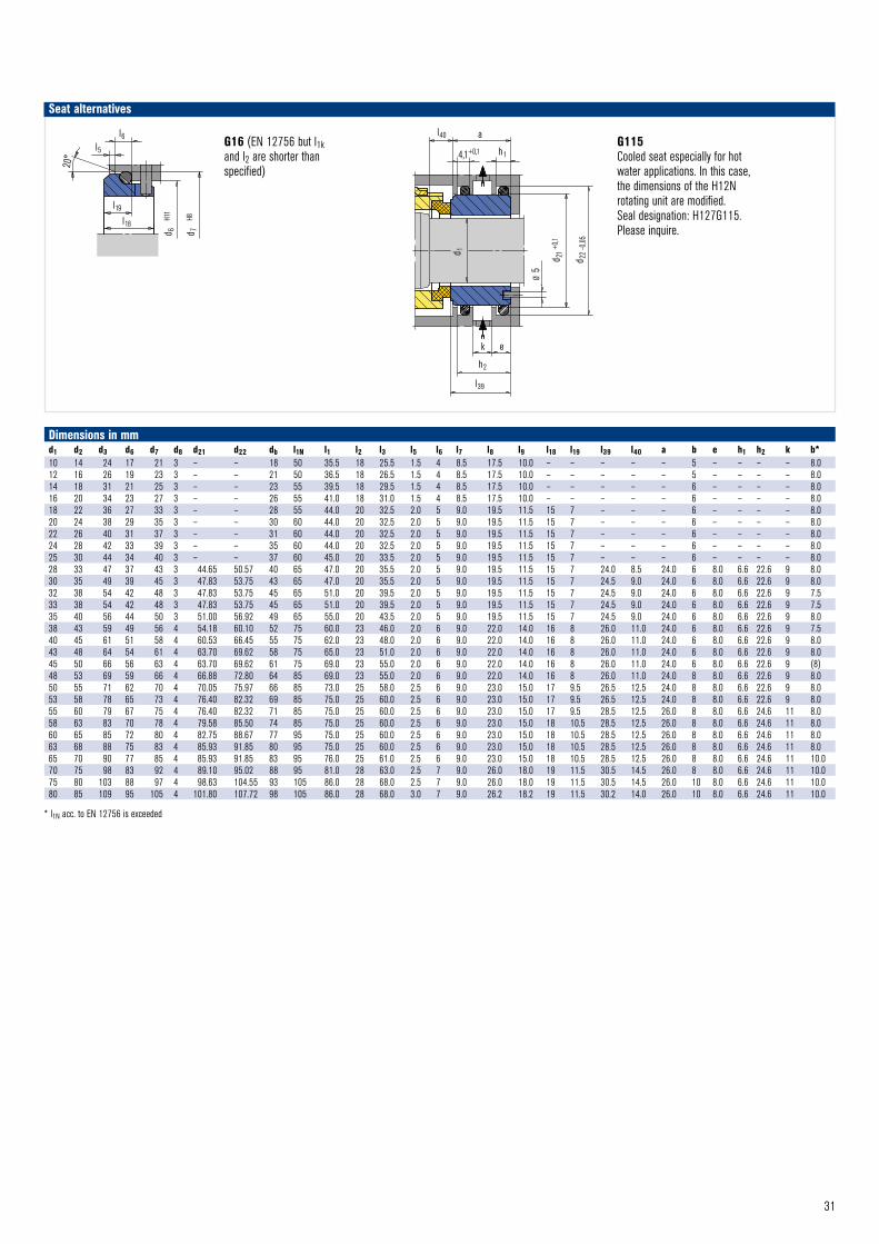
31
G16 (EN 12756 but l1k and l2 are shorter than specified)
G115Cooled seat especially for hot water applications. In this case, the dimensions of the H12N rotating unit are modified. Seal designation: H127G115. Please inquire.
Seat alternatives
d 7
H8
d 6
H11
l6l5
20°
l19
l18
G16 © EagleBurgmann
Dimensions in mmd1 d2 d3 d6 d7 d8 d21 d22 db l1N l1 l2 l3 l5 l6 l7 l8 l9 l18 l19 l39 l40 a b e h1 h2 k b*10 14 24 17 21 3 – – 18 50 35.5 18 25.5 1.5 4 8.5 17.5 10.0 – – – – – 5 – – – – 8.012 16 26 19 23 3 – – 21 50 36.5 18 26.5 1.5 4 8.5 17.5 10.0 – – – – – 5 – – – – 8.014 18 31 21 25 3 – – 23 55 39.5 18 29.5 1.5 4 8.5 17.5 10.0 – – – – – 6 – – – – 8.016 20 34 23 27 3 – – 26 55 41.0 18 31.0 1.5 4 8.5 17.5 10.0 – – – – – 6 – – – – 8.018 22 36 27 33 3 – – 28 55 44.0 20 32.5 2.0 5 9.0 19.5 11.5 15 7 – – – 6 – – – – 8.020 24 38 29 35 3 – – 30 60 44.0 20 32.5 2.0 5 9.0 19.5 11.5 15 7 – – – 6 – – – – 8.022 26 40 31 37 3 – – 31 60 44.0 20 32.5 2.0 5 9.0 19.5 11.5 15 7 – – – 6 – – – – 8.024 28 42 33 39 3 – – 35 60 44.0 20 32.5 2.0 5 9.0 19.5 11.5 15 7 – – – 6 – – – – 8.025 30 44 34 40 3 – – 37 60 45.0 20 33.5 2.0 5 9.0 19.5 11.5 15 7 – – – 6 – – – – 8.028 33 47 37 43 3 44.65 50.57 40 65 47.0 20 35.5 2.0 5 9.0 19.5 11.5 15 7 24.0 8.5 24.0 6 8.0 6.6 22.6 9 8.030 35 49 39 45 3 47.83 53.75 43 65 47.0 20 35.5 2.0 5 9.0 19.5 11.5 15 7 24.5 9.0 24.0 6 8.0 6.6 22.6 9 8.032 38 54 42 48 3 47.83 53.75 45 65 51.0 20 39.5 2.0 5 9.0 19.5 11.5 15 7 24.5 9.0 24.0 6 8.0 6.6 22.6 9 7.533 38 54 42 48 3 47.83 53.75 45 65 51.0 20 39.5 2.0 5 9.0 19.5 11.5 15 7 24.5 9.0 24.0 6 8.0 6.6 22.6 9 7.535 40 56 44 50 3 51.00 56.92 49 65 55.0 20 43.5 2.0 5 9.0 19.5 11.5 15 7 24.5 9.0 24.0 6 8.0 6.6 22.6 9 8.038 43 59 49 56 4 54.18 60.10 52 75 60.0 23 46.0 2.0 6 9.0 22.0 14.0 16 8 26.0 11.0 24.0 6 8.0 6.6 22.6 9 7.540 45 61 51 58 4 60.53 66.45 55 75 62.0 23 48.0 2.0 6 9.0 22.0 14.0 16 8 26.0 11.0 24.0 6 8.0 6.6 22.6 9 8.043 48 64 54 61 4 63.70 69.62 58 75 65.0 23 51.0 2.0 6 9.0 22.0 14.0 16 8 26.0 11.0 24.0 6 8.0 6.6 22.6 9 8.045 50 66 56 63 4 63.70 69.62 61 75 69.0 23 55.0 2.0 6 9.0 22.0 14.0 16 8 26.0 11.0 24.0 6 8.0 6.6 22.6 9 (8)48 53 69 59 66 4 66.88 72.80 64 85 69.0 23 55.0 2.0 6 9.0 22.0 14.0 16 8 26.0 11.0 24.0 8 8.0 6.6 22.6 9 8.050 55 71 62 70 4 70.05 75.97 66 85 73.0 25 58.0 2.5 6 9.0 23.0 15.0 17 9.5 26.5 12.5 24.0 8 8.0 6.6 22.6 9 8.053 58 78 65 73 4 76.40 82.32 69 85 75.0 25 60.0 2.5 6 9.0 23.0 15.0 17 9.5 26.5 12.5 24.0 8 8.0 6.6 22.6 9 8.055 60 79 67 75 4 76.40 82.32 71 85 75.0 25 60.0 2.5 6 9.0 23.0 15.0 17 9.5 28.5 12.5 26.0 8 8.0 6.6 24.6 11 8.058 63 83 70 78 4 79.58 85.50 74 85 75.0 25 60.0 2.5 6 9.0 23.0 15.0 18 10.5 28.5 12.5 26.0 8 8.0 6.6 24.6 11 8.060 65 85 72 80 4 82.75 88.67 77 95 75.0 25 60.0 2.5 6 9.0 23.0 15.0 18 10.5 28.5 12.5 26.0 8 8.0 6.6 24.6 11 8.063 68 88 75 83 4 85.93 91.85 80 95 75.0 25 60.0 2.5 6 9.0 23.0 15.0 18 10.5 28.5 12.5 26.0 8 8.0 6.6 24.6 11 8.065 70 90 77 85 4 85.93 91.85 83 95 76.0 25 61.0 2.5 6 9.0 23.0 15.0 18 10.5 28.5 12.5 26.0 8 8.0 6.6 24.6 11 10.070 75 98 83 92 4 89.10 95.02 88 95 81.0 28 63.0 2.5 7 9.0 26.0 18.0 19 11.5 30.5 14.5 26.0 8 8.0 6.6 24.6 11 10.075 80 103 88 97 4 98.63 104.55 93 105 86.0 28 68.0 2.5 7 9.0 26.0 18.0 19 11.5 30.5 14.5 26.0 10 8.0 6.6 24.6 11 10.080 85 109 95 105 4 101.80 107.72 98 105 86.0 28 68.0 3.0 7 9.0 26.2 18.2 19 11.5 30.2 14.0 26.0 10 8.0 6.6 24.6 11 10.0
* l1N acc. to EN 12756 is exceeded
l40 a
4,1+0,1 h1
d 1
d 21
+0,1
d 22
– 0,0
5
Ø 5
k e
l39
h2
G115 © EagleBurgmann

32
H3B
Mechanical seals • Mechanical seals for pumps • Pusher seals
Dimensions in mmd d1 d2 d3 d4 d5 d6 l l1 l2 l3 l4 l524 20 38 40 29 35 3 62 49 13 42 5 226 22 40 42 31 37 3 62 49 13 42 5 228 24 42 44 33 39 3 64 51 13 44 5 230 25 44 46 34 40 3 64 51 13 44 5 233 28 47 49 37 43 3 64 51 13 44 5 235 30 49 51 39 45 3 68 55 13 48 5 238 33 54 58 42 48 3 71 58 13 51 5 240 35 56 60 44 50 3 73 60 13 53 5 243 38 59 63 50 56 4 76 61 15 53 5 245 40 61 65 52 58 4 76 61 15 53 5 248 43 64 68 55 61 4 76 61 15 53 5 250 45 66 70 57 63 4 80 65 15 57 5 253 48 69 73 60 66 4 80 65 15 57 5 255 50 71 75 62 68 4 82 65 17 57 5 258 53 76 83 65 71 4 84 68 16 59 5 260 55 78 85 67 73 4 84 68 16 59 5 263 58 81 88 70 79 4 84 68 16 59 7 2.565 60 84 90 72 81 4 88 72 16 63 7 2.568 63 87 93 75 84 4 88 72 16 63 7 2.570 65 90 95 77 86 4 89 73 16 64 7 2.575 70 95 104 83 92 4 94 75 19 66 7 2.580 75 100 109 88 97 4 94 75 19 66 7 2.585 80 107 114 96 105 4 100 81 19 72 7 2.590 85 112 119 101 110 4 100 82 18 72 7 2.595 90 119 124 106 115 4 105 87 18 77 7 2.5
100 95 124 129 111 120 4 105 87 18 77 7 2.5105 100 129 134 116 125 4 105 87 18 77 7 2.5
Item Description1.1 Seal face1.2, 3 O-Ring1.3 Spring1.4 Drive collar1.5 Set screw2 Seat
l ±0,5
l2l1
9min
d 3m
in
d 2
d
h7
1.5 1.4 1.3 1.2 1.1 2 3
l3
2
30°
d 1
d 4H1
1
H7d 5
20°
l5
l4
5
H3B © EagleBurgmann
n x d6
Features• Single Seal• Balanced• Independent of direction of rotation
Advantages• Excellent torque transmission due to clutch drive between seal head and drive collar.
Operating range (see note on page 1)Pressure: p = 12 bar (174 PSI)Temperature: t = –20 °C … +160 °C (–4 °F … +320 °F)Sliding velocity: vg = 20 m/s (66 ft/s)Viscosity: … 300 mPa·sSolids content: … 7 %
MaterialsSeal face and seat: Silicon carbide (Q1), Tungsten carbide (U7)Metal parts: 1.4401 (G)Secondary seals: FKM (V)
Standards and approvals• ISO 3096
Recommended applications• Process industry• Oil and gas industry• High viscous media (tar, heavy oils)• Process pumps

33
l1´
1.2
d 2´
H8 © EagleBurgmann
l3
Ø 3
2 1.1 1.3
3 1.4 1.2
d 1
d 2
+0,
3
d 5
min
d 6
±0,
1
d 3
H7d 4
l1
8 2
H10 © EagleBurgmann
H10 / H8
Mechanical seals • Mechanical seals for pumps • Pusher seals
Item Part no. to DIN 24250 Description1.1 472 Seal face 473 Seal face housing1.2 485 Drive collar1.3 O-Ring 1.4 477 Spring2 475 Rotating seat*3 412.2 O-Ring* The stationary seat design is chosen according to the specific
requirements and conditions of operation.
H8Dimensions, items and decription as H10. Drive collars and housings for item 1.2 are made of deep-drawn stainless steel sheet.
Product variant
Dimensions in mmd1 d2 d2’ d3 d4 d5 d6 l l1 l1’
15 16 17 42 22.6 21 34 17 15 1618 19 – 45 25.6 24 37 17 15 –20 21 22 48 27.6 26 40 17 15 1622 23 24 50 29.6 28 42 17 15 1625 26 27 52 32.8 31 44 17 15 1628 29 – 55 35.8 34 47 17 15 –30 31 32 58 37.8 36 50 17 15 1632 33 34 60 39.8 38 52 17 15 1635 36 37 62 42.8 41 54 17 15 1638 39 40 65 45.9 44 57 17 15 1640 41 42 68 47.9 46 60 17 15 1642 43 44 72 49.9 48 64 17 15 1645 46 47 75 52.9 51 67 17 15 1648 49 – 80 55.9 54 72 17 15 –50 51 52 80 58.2 56 72 17 15 1652 53 – 82 60.2 58 74 17 15 –55 56 57 85 63.2 61 77 17 15 1658 59 – 90 66.7 64 82 17 15 –60 61 62 90 68.7 66 82 17 15 1665 66 67 95 73.7 71 87 19 16.5 1868 69 70 100 76.7 74 92 19 16.5 1870 71 72 100 78.7 76 92 19 16.5 1875 76 77 108 83.7 81 100 19 16.5 1880 81 82 112 88.7 86 104 19 16.5 1885 86 87 118 93.7 91 110 19 16.5 1890 91 92 122 99.5 96 114 19 16.5 1895 96 97 128 104.5 101 120 19 16.5 18
100 101 102 132 109.5 106 124 19 16.5 18Axial tolerances: l ±0.5 H10, l ±0.2 H8
Features• Single seal• Balanced• Independent of direction of rotation• Stationary multiple springs
Advantages• Insensitive to solids in the medium• Very short axial installation length (analog lip seals) combined with high pressurre capability
• No damage of the shaft by dynamically loaded O-Ring• Due to the stationary design insensitive to shaft misalignements
• Compact ready-to-install unit
Operating range (see note on page 1)Shaft diameter: d1 = 15 … 100 mm (0.6" … 3.9")Pressure: p1 = 25 bar (363 PSI)Temperature: t = –40 °C … +180 °C (–40 °F … +356 °F)Sliding velocity: vg = 35 m/s (115 ft/s)
MaterialsSeal face: Carbon graphite antimony impregnated (A), Carbon graphite resin impregnated (B)
Recommended applications• Process industry• Chemical industry• Water and waste water technology• Lube oils • Roller seal• Bearing seal• All seal chambers with a very short axial installation length

34
45°45°A
sa1
da
CARTEX_cover_mach © EagleBurgmann
45° 45°A
s
da
a1
CARTEX_cover_cast © EagleBurgmann
Machined cover version
Cast cover version
7 5 4 1 8 10
6 14 11 2 3 9
d 3 d 2 d 1 h
6
l2
l4l3
15
1312
l1
Cartex © EagleBurgmann
Cartex-SN
Cartex Single seals
Mechanical seals · Mechanical seals for pumps · Standard cartridge seals
Item Description1 Seal face2, 5, 7 O-Ring3 Spring4 Seat6 Shaft sleeve8 Drive collar9 Set screw10 Snap ring11 Housing12 Assembly fixture13 Screw14 Gasket15 Screw plug 16 Lip seal (-QN), throttle ring (-TN)
MaterialsSeal face: Silicon carbide (Q1), Carbon graphite resin impregnated (B), Tungsten carbide (U2)Seat: Silicon carbide (Q1)Secondary seals: FKM (V), EPDM (E), FFKM (K), Perflourocarbon rubber/PTFE (U1)Springs: Hastelloy® C-4 (M)Metal parts: CrNiMo steel (G), CrNiMo cast steel (G)
Recommended applications• Process industry• Petrochemical industry• Chemical industry• Pharmaceutical industry• Power plant technology• Pulp and paper industry• Water and waste water technology• Mining industry• Food and beverage industry• Sugar industry• Universally applicable• Centrifugal pumps• Eccentric screw pumps• Process pumps
Features• Single seal• Cartridge• Balanced• Independent of direction of rotation• Single seals without connections (-SNO), with flush (-SN) and with quench combined with lip seal (-QN) or throttle ring (-TN)
• Additional variants available for ANSI pumps (e. g.-ABPN) and eccentric screw pumps (-Vario)
Advantages• Ideal seal for standardizations• Universal applicable for packings conversions, retrofits or original equipment
• No dimensional modification of the seal chamber (centrifugal pumps) necessary, small radial installation height
• No damage of the shaft by dynamically loaded O-Ring• Extended service life• Installation faults are avoided, cost-effective• No damage caused by dirt entered during assembly• Straightforward and easy installation due to pre-assembled unit (reduced down-times)
• Individual adaptation to pump design possible• Customer specific versions available
Operating range (see note on page 1)Cartex-SN, -SNO, -QN, -TN, -Vario
Shaft diameter: d1 = 25 … 100 mm (1.000" … 4.000")Other sizes on requestTemperature: t = –40 °C … +220 °C (–40 °F … +428 °F)(Check O-Ring resistance)
Sliding face material combination BQ1Pressure: p1 = 25 bar (363 PSI)Sliding velocity: vg = 16 m/s (52 ft/s)
Sliding face material combination Q1Q1 or U2Q1Pressure: p1 = 12 bar (174 PSI)Sliding velocity: vg = 10 m/s (33 ft/s)
Axial movement: ±1.0 mm, d1 ≥75 ±1.5 mm
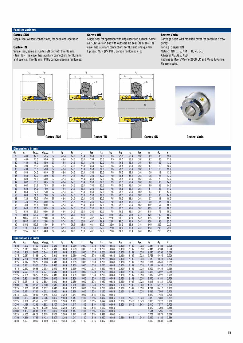
35
Cartex-SNOSingle seal without connections, for dead-end operation.
Cartex-TNSingle seal, same as Cartex-SN but with throttle ring (item 16). The cover has auxiliary connections for flushing and quench. Throttle ring: PTFE carbon-graphite reinforced.
Cartex-QNSingle seal for operation with unpressurized quench. Same as “-SN” version but with outboard lip seal (item 16). The cover has auxiliary connections for flushing and quench. Lip seal: NBR (P), PTFE carbon reinforced (T3)
Cartex-VarioCartridge seals with modified cover for eccentric screw pumps. For e. g. Seepex BN, Netzsch NM … S, NM … B, NE (P),Allweiler AE, AEB, AED,Robbins & Myers/Moyno 2000 CC and Mono E-Range.Please inquire.
Product variants
l13 l12
l14
CARTEX–SNO © EagleBurgmann
l15
l16l17
15
16
Cartex–TN © EagleBurgmann Cartex–QN © EagleBurgmann
16
15
l15
l17 l16
Cartex-SNO Cartex-TN Cartex-QN Cartex-Vario
Dimensions in mmd1 d2 d3min. d3max. l1 l2 l3 l4 l12 l13 l14 l15 l16 l17 a1 da s25 43.0 44.0 51.5 67 42.4 24.6 25.4 35.0 32.0 17.5 79.5 53.4 26.1 62 105 13.228 46.0 47.0 52.0 67 42.4 24.6 25.4 35.0 32.0 17.5 79.5 53.4 26.1 62 105 13.230 48.0 49.0 56.0 67 42.4 24.6 25.4 35.0 32.0 17.5 79.5 53.4 26.1 65 105 13.232 49.8 51.0 57.0 67 42.4 24.6 25.4 35.0 32.0 17.5 79.5 53.4 26.1 67 110 13.233 49.8 51.0 57.0 67 42.4 24.6 25.4 35.0 32.0 17.5 79.5 53.4 26.1 67 110 13.235 53.0 54.0 61.5 67 42.4 24.6 25.4 35.0 32.0 17.5 79.5 53.4 26.1 70 113 13.238 56.0 57.0 66.0 67 42.4 24.6 25.4 35.0 32.0 17.5 79.5 53.4 26.1 75 123 13.240 58.0 59.0 68.0 67 42.4 24.6 25.4 35.0 32.0 17.5 79.5 53.4 26.1 75 123 14.242 60.5 61.5 69.5 67 42.4 24.6 25.4 35.0 32.0 17.5 79.5 53.4 26.1 80 133 14.243 60.5 61.5 70.5 67 42.4 24.6 25.4 35.0 32.0 17.5 79.5 53.4 26.1 80 133 14.245 62.5 64.0 73.0 67 42.4 24.6 25.4 35.0 32.0 17.5 79.5 53.4 26.1 81 138 14.248 65.6 67.0 75.0 67 42.4 24.6 25.4 35.0 32.0 17.5 79.5 53.4 26.1 84 138 14.250 68.0 69.0 78.0 67 42.4 24.6 25.4 35.0 32.0 17.5 79.5 53.4 26.1 87 148 14.253 72.0 73.0 87.0 67 42.4 24.6 25.4 35.0 32.0 17.5 79.5 53.4 26.1 97 148 18.055 73.0 74.0 83.0 67 42.4 24.6 25.4 35.0 32.0 17.5 79.5 53.4 26.1 90 148 18.060 78.0 79.0 91.0 67 42.4 24.6 25.4 35.0 32.0 17.5 79.5 53.4 26.1 102 157 18.065 84.8 85.7 98.5 67 42.4 24.6 25.4 35.0 32.0 17.5 79.5 53.4 26.1 109 163 18.070 93.0 95.0 108.0 67 42.4 24.6 25.4 35.0 32.0 17.5 79.5 53.4 26.1 118 178 18.075 100.0 101.6 118.0 84 57.4 26.6 28.0 46.1 37.9 22.0 98.0 63.9 34.1 129 190 18.080 106.4 108.0 124.0 84 57.4 26.6 28.0 46.1 37.9 22.0 98.0 63.9 34.1 135 195 18.085 109.5 111.1 128.0 84 57.4 26.6 28.0 46.1 37.9 22.0 98.0 63.9 34.1 139 198 22.090 115.9 117.5 135.0 84 57.4 26.6 28.0 46.1 37.9 22.0 98.0 63.9 34.1 145 205 22.095 119.1 120.7 138.0 84 57.4 26.6 28.0 46.1 37.9 22.0 98.0 63.9 34.1 148 208 22.0
100 125.4 127.0 144.0 84 57.4 26.6 28.0 46.1 37.9 22.0 98.0 63.9 34.1 154 218 22.0
Dimensions in inchd1 d2 d3min. d3max. l1 l2 l3 l4 l12 l13 l14 l15 l16 l17 a1 da s1.000 1.693 1.750 2.008 2.640 1.669 0.969 1.000 1.378 1.260 0.689 3.130 2.102 1.028 2.441 4.134 0.5201.125 1.811 1.850 2.047 2.640 1.669 0.969 1.000 1.378 1.260 0.689 3.130 2.102 1.028 2.441 4.134 0.5201.250 1.969 2.008 2.244 2.640 1.669 0.969 1.000 1.378 1.260 0.689 3.130 2.102 1.028 2.640 4.252 0.5201.375 2.087 2.126 2.421 2.640 1.669 0.969 1.000 1.378 1.260 0.689 3.130 2.102 1.028 2.756 4.449 0.5201.500 2.205 2.244 2.589 2.640 1.669 0.969 1.000 1.378 1.260 0.689 3.130 2.102 1.028 2.953 4.843 0.5201.625 2.344 2.375 2.700 2.640 1.669 0.969 1.000 1.378 1.260 0.689 3.130 2.102 1.028 3.031 4.843 0.5591.750 2.461 2.520 2.874 2.640 1.669 0.969 1.000 1.378 1.260 0.689 3.130 2.102 1.028 3.189 5.433 0.5591.875 2.583 2.638 2.953 2.640 1.669 0.969 1.000 1.378 1.260 0.689 3.130 2.102 1.028 3.307 5.433 0.5592.000 2.677 2.717 3.071 2.640 1.669 0.969 1.000 1.378 1.260 0.689 3.130 2.102 1.028 3.425 5.827 0.5592.125 2.835 2.875 3.425 2.640 1.669 0.969 1.000 1.378 1.260 0.689 3.130 2.102 1.028 3.819 5.827 0.7092.250 2.961 3.000 3.560 2.640 1.669 0.969 1.000 1.378 1.260 0.689 3.130 2.102 1.028 3.940 6.181 0.7092.375 3.071 3.110 3.583 2.640 1.669 0.969 1.000 1.378 1.260 0.689 3.130 2.102 1.028 4.016 6.181 0.7092.500 3.213 3.250 3.800 2.640 1.669 0.969 1.000 1.378 1.260 0.689 3.130 2.102 1.028 4.173 6.417 0.7092.625 3.339 3.338 3.937 2.640 1.669 0.969 1.000 1.378 1.260 0.689 3.130 2.102 1.028 4.291 6.417 0.7092.750 3.661 3.740 4.252 2.640 1.669 0.969 1.000 1.378 1.260 0.689 3.130 2.102 1.028 4.646 7.008 0.7092.875 3.937 4.000 4.646 3.307 2.260 1.047 1.000 1.815 1.492 0.866 – – – 5.079 7.480 0.7093.000 3.937 4.000 4.646 3.307 2.260 1.047 1.100 1.815 1.492 0.866 3.858 2.516 1.343 5.079 7.480 0.7093.125 4.189 4.252 4.882 3.307 2.260 1.047 1.100 1.815 1.492 0.866 3.858 2.516 1.343 5.315 7.677 0.7093.250 4.189 4.252 4.882 3.307 2.260 1.047 1.100 1.815 1.492 0.866 3.858 2.516 1.343 5.315 7.677 0.7093.375 4.311 4.374 5.039 3.307 2.260 1.047 1.100 1.815 1.492 0.866 – – – 5.472 7.795 0.8663.500 4.437 4.500 5.157 3.307 2.260 1.047 1.100 1.815 1.492 0.866 – – – 5.591 7.795 0.8663.625 4.563 4.626 5.315 3.307 2.260 1.047 1.100 1.815 1.492 0.866 – – – 5.709 8.071 0.8663.750 4.689 4.752 5.433 3.307 2.260 1.047 1.100 1.815 1.492 0.866 3.858 2.516 1.343 5.827 8.189 0.8664.000 4.937 5.000 5.669 3.307 2.260 1.047 1.100 1.815 1.492 0.866 – – – 6.063 8.583 0.866
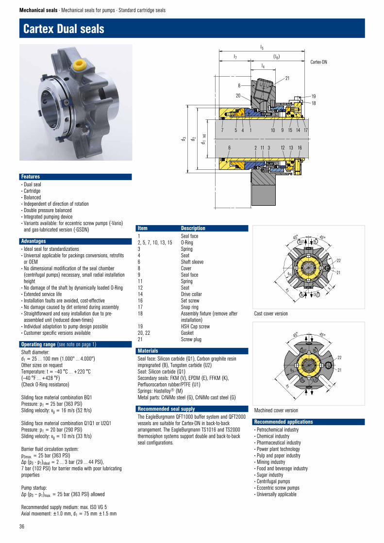
36
OUT IN
IN OUT
da
22
21
s
45° 45°
a2
CARTEX – DN © EagleBurgmann
Version Drehdeckel
Machined cover version
45° 45°
d a
a2
22
21
sOUTIN
OUT IN
CARTEX– DN © EagleBurgmannVersion: Gussdeckel
Cast cover version
7 5 4 1 10 15 14 17 9
6 2 11 3 12 13 16
1918
218
20
l5
l7 ( l6)
l4
d 3 d 2
d 1
h6
Cartex–DN © EagleBurgmann
Cartex Dual seals
Mechanical seals · Mechanical seals for pumps · Standard cartridge seals
Cartex-DN
Item Description1 Seal face2, 5, 7, 10, 13, 15 O-Ring3 Spring4 Seat6 Shaft sleeve8 Cover9 Seal face11 Spring12 Seat14 Drive collar16 Set screw17 Snap ring18 Assembly fixture (remove after installation)19 HSH Cap screw20, 22 Gasket21 Screw plug
MaterialsSeal face: Silicon carbide (Q1), Carbon graphite resin impregnated (B), Tungsten carbide (U2)Seat: Silicon carbide (Q1)Secondary seals: FKM (V), EPDM (E), FFKM (K), Perfluorocarbon rubber/PTFE (U1)Springs: Hastelloy® (M)Metal parts: CrNiMo steel (G), CrNiMo cast steel (G)
Recommended seal supplyThe EagleBurgmann QFT1000 buffer system and QFT2000 vessels are suitable for Cartex-DN in back-to-back arrangement. The EagleBurgmann TS1016 and TS2000 thermosiphon systems support double and back-to-back seal configurations.
Recommended applications• Petrochemical industry• Chemical industry• Pharmaceutical industry• Power plant technology• Pulp and paper industry• Mining industry• Food and beverage industry• Sugar industry• Centrifugal pumps• Eccentric screw pumps• Universally applicable
Features• Dual seal• Cartridge• Balanced• Independent of direction of rotation• Double pressure balanced• Integrated pumping device• Variants available: for eccentric screw pumps (-Vario) and gas-lubricated version (-GSDN)
Advantages• Ideal seal for standardizations• Universal applicable for packings conversions, retrofits or OEM
• No dimensional modification of the seal chamber (centrifugal pumps) necessary, small radial installation height
• No damage of the shaft by dynamically loaded O-Ring• Extended service life• Installation faults are avoided, cost-effective• No damage caused by dirt entered during assembly• Straightforward and easy installation due to pre-assembled unit (reduced down-times)
• Individual adaptation to pump design possible• Customer specific versions available
Operating range (see note on page 1)Shaft diameter: d1 = 25 … 100 mm (1.000" … 4.000")Other sizes on requestTemperature: t = –40 °C … +220 °C (–40 °F … +428 °F)(Check O-Ring resistance)
Sliding face material combination BQ1Pressure: p1 = 25 bar (363 PSI)Sliding velocity: vg = 16 m/s (52 ft/s)
Sliding face material combination Q1Q1 or U2Q1Pressure: p1 = 20 bar (290 PSI)Sliding velocity: vg = 10 m/s (33 ft/s)
Barrier fluid circulation system:p3max. = 25 bar (363 PSI)Δp (p3 - p1)ideal = 2 … 3 bar (29 … 44 PSI), 7 bar (102 PSI) for barrier media with poor lubricating properties
Pump startup:Δp (p3 – p1)max. = 25 bar (363 PSI) allowed
Recommended supply medium: max. ISO VG 5Axial movement: ±1.0 mm, d1 = 75 mm ±1.5 mm
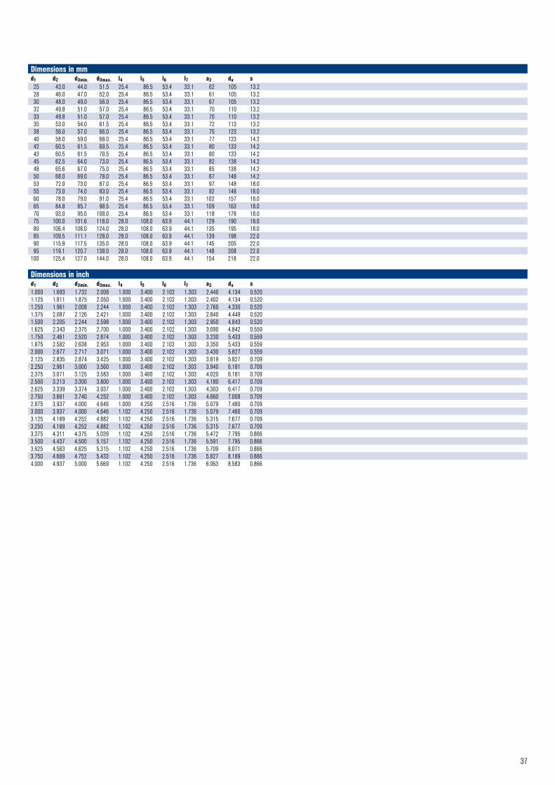
37
Dimensions in mmd1 d2 d3min. d3max. l4 l5 l6 l7 a2 da s25 43.0 44.0 51.5 25.4 86.5 53.4 33.1 62 105 13.228 46.0 47.0 52.0 25.4 86.5 53.4 33.1 61 105 13.230 48.0 49.0 56.0 25.4 86.5 53.4 33.1 67 105 13.232 49.8 51.0 57.0 25.4 86.5 53.4 33.1 70 110 13.233 49.8 51.0 57.0 25.4 86.5 53.4 33.1 70 110 13.235 53.0 54.0 61.5 25.4 86.5 53.4 33.1 72 113 13.238 56.0 57.0 66.0 25.4 86.5 53.4 33.1 75 123 13.240 58.0 59.0 68.0 25.4 86.5 53.4 33.1 77 123 14.242 60.5 61.5 69.5 25.4 86.5 53.4 33.1 80 133 14.243 60.5 61.5 70.5 25.4 86.5 53.4 33.1 80 133 14.245 62.5 64.0 73.0 25.4 86.5 53.4 33.1 82 138 14.248 65.6 67.0 75.0 25.4 86.5 53.4 33.1 85 138 14.250 68.0 69.0 78.0 25.4 86.5 53.4 33.1 87 148 14.253 72.0 73.0 87.0 25.4 86.5 53.4 33.1 97 148 18.055 73.0 74.0 83.0 25.4 86.5 53.4 33.1 92 148 18.060 78.0 79.0 91.0 25.4 86.5 53.4 33.1 102 157 18.065 84.8 85.7 98.5 25.4 86.5 53.4 33.1 109 163 18.070 93.0 95.0 108.0 25.4 86.5 53.4 33.1 118 178 18.075 100.0 101.6 118.0 28.0 108.0 63.9 44.1 129 190 18.080 106.4 108.0 124.0 28.0 108.0 63.9 44.1 135 195 18.085 109.5 111.1 128.0 28.0 108.0 63.9 44.1 139 198 22.090 115.9 117.5 135.0 28.0 108.0 63.9 44.1 145 205 22.095 119.1 120.7 138.0 28.0 108.0 63.9 44.1 148 208 22.0
100 125.4 127.0 144.0 28.0 108.0 63.9 44.1 154 218 22.0
Dimensions in inchd1 d2 d3min. d3max. l4 l5 l6 l7 a2 da s1.000 1.693 1.732 2.008 1.000 3.400 2.102 1.303 2.440 4.134 0.5201.125 1.811 1.875 2.050 1.000 3.400 2.102 1.303 2.402 4.134 0.5201.250 1.961 2.008 2.244 1.000 3.400 2.102 1.303 2.760 4.330 0.5201.375 2.087 2.126 2.421 1.000 3.400 2.102 1.303 2.840 4.449 0.5201.500 2.205 2.244 2.598 1.000 3.400 2.102 1.303 2.950 4.843 0.5201.625 2.343 2.375 2.700 1.000 3.400 2.102 1.303 3.090 4.842 0.5591.750 2.461 2.520 2.874 1.000 3.400 2.102 1.303 3.230 5.433 0.5591.875 2.582 2.638 2.953 1.000 3.400 2.102 1.303 3.350 5.433 0.5592.000 2.677 2.717 3.071 1.000 3.400 2.102 1.303 3.430 5.827 0.5592.125 2.835 2.874 3.425 1.000 3.400 2.102 1.303 3.819 5.827 0.7092.250 2.961 3.000 3.560 1.000 3.400 2.102 1.303 3.940 6.181 0.7092.375 3.071 3.125 3.583 1.000 3.400 2.102 1.303 4.020 6.181 0.7092.500 3.213 3.300 3.800 1.000 3.400 2.102 1.303 4.180 6.417 0.7092.625 3.339 3.374 3.937 1.000 3.400 2.102 1.303 4.303 6.417 0.7092.750 3.661 3.740 4.252 1.000 3.400 2.102 1.303 4.660 7.008 0.7092.875 3.937 4.000 4.646 1.000 4.250 2.516 1.736 5.079 7.480 0.7093.000 3.937 4.000 4.646 1.102 4.250 2.516 1.736 5.079 7.480 0.7093.125 4.189 4.252 4.882 1.102 4.250 2.516 1.736 5.315 7.677 0.7093.250 4.189 4.252 4.882 1.102 4.250 2.516 1.736 5.315 7.677 0.7093.375 4.311 4.375 5.039 1.102 4.250 2.516 1.736 5.472 7.795 0.8663.500 4.437 4.500 5.157 1.102 4.250 2.516 1.736 5.591 7.795 0.8663.625 4.563 4.625 5.315 1.102 4.250 2.516 1.736 5.709 8.071 0.8663.750 4.689 4.752 5.433 1.102 4.250 2.516 1.736 5.827 8.189 0.8664.000 4.937 5.000 5.669 1.102 4.250 2.516 1.736 6.063 8.583 0.866
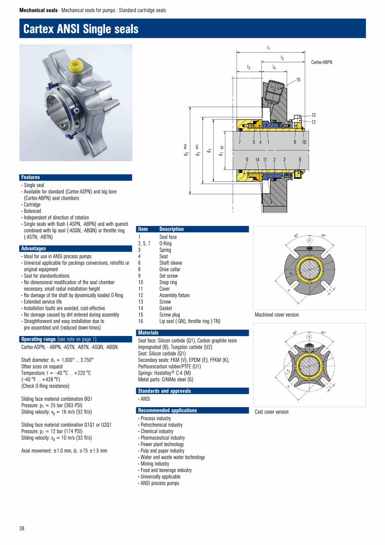
38
7 5 4 1 8 10
6 14 11 2 3 9
1312
15
l1
l2
l3 l4
d 3
max
d 3
min
d 1
h6
d 2
CARTEX–ABPN © EagleBurgmann
45° 45°A
sa1
d a
Cartex–ANSI–Seite 1 © EagleBurgmannMachined cover version
d a
a1 s
45° 45°A
Cartex–ANSI–Seite-2 © EagleBurgmannCast cover version
Cartex-ABPN
Cartex ANSI Single seals
Mechanical seals · Mechanical seals for pumps · Standard cartridge seals
Item Description1 Seal face2, 5, 7 O-Ring3 Spring4 Seat6 Shaft sleeve8 Drive collar9 Set screw10 Snap ring11 Cover12 Assembly fixture13 Screw14 Gasket15 Screw plug 16 Lip seal (-QN), throttle ring (-TN)
MaterialsSeal face: Silicon carbide (Q1), Carbon graphite resin impregnated (B), Tungsten carbide (U2)Seat: Silicon carbide (Q1)Secondary seals: FKM (V), EPDM (E), FFKM (K), Perflourocarbon rubber/PTFE (U1)Springs: Hastelloy® C-4 (M)Metal parts: CrNiMo steel (G)
Standards and approvals• ANSI
Recommended applications• Process industry• Petrochemical industry• Chemical industry• Pharmaceutical industry• Power plant technology• Pulp and paper industry• Water and waste water technology• Mining industry• Food and beverage industry• Universally applicable• ANSI process pumps
Features• Single seal• Available for standard (Cartex-ASPN) and big bore (Cartex-ABPN) seal chambers
• Cartridge• Balanced• Independent of direction of rotation• Single seals with flush (-ASPN, -ABPN) and with quench combined with lip seal (-ASQN, -ABQN) or throttle ring (-ASTN, -ABTN)
Advantages• Ideal for use in ANSI process pumps • Universal applicable for packings conversions, retrofits or original equipment
• Seal for standardizations• No dimensional modification of the seal chamber necessary, small radial installation height
• No damage of the shaft by dynamically loaded O-Ring• Extended service life• Installation faults are avoided, cost-effective• No damage caused by dirt entered during assembly• Straightforward and easy installation due to pre-assembled unit (reduced down-times)
Operating range (see note on page 1)Cartex-ASPN, - ABPN, -ASTN, -ABTN, -ASQN, -ABQN
Shaft diameter: d1 = 1.000" … 3.750"Other sizes on requestTemperature: t = –40 °C … +220 °C (–40 °F … +428 °F)(Check O-Ring resistance)
Sliding face material combination BQ1Pressure: p1 = 25 bar (363 PSI)Sliding velocity: vg = 16 m/s (52 ft/s)
Sliding face material combination Q1Q1 or U2Q1Pressure: p1 = 12 bar (174 PSI)Sliding velocity: vg = 10 m/s (33 ft/s)
Axial movement: ±1.0 mm, d1 ≥75 ±1.5 mm
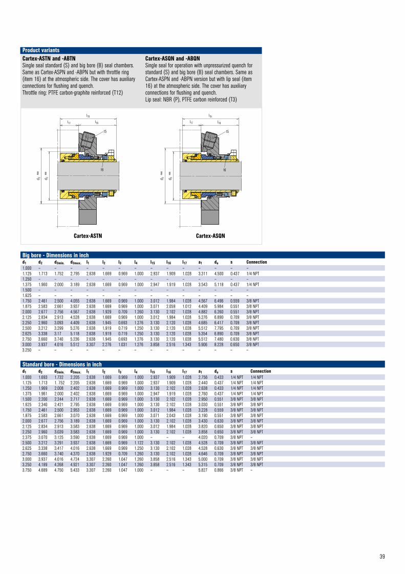
39
16
15
l15
l16l17
d 3
max
d 3
min
Cartex–ASTN © EagleBurgmann
15
l15
l17 l16
16
d 3
max
d 3
min
Cartex–ASQN © EagleBurgmannCartex-ASTN Cartex-ASQN
Cartex-ASTN and -ABTNSingle seal standard (S) and big bore (B) seal chambers. Same as Cartex-ASPN and -ABPN but with throttle ring (item 16) at the atmospheric side. The cover has auxiliary connections for flushing and quench. Throttle ring: PTFE carbon-graphite reinforced (T12)
Cartex-ASQN and -ABQNSingle seal for operation with unpressurized quench for standard (S) and big bore (B) seal chambers. Same as Cartex-ASPN and -ABPN version but with lip seal (item 16) at the atmospheric side. The cover has auxiliary connections for flushing and quench. Lip seal: NBR (P), PTFE carbon reinforced (T3)
Product variants
Big bore - Dimensions in inchd1 d2 d3min. d3max. l1 l2 l3 l4 l15 l16 l17 a1 da s Connection1.000 – – – – – – – – – – – – – –1.125 1.713 1.752 2.795 2.638 1.669 0.969 1.000 2.937 1.909 1.028 3.311 4.500 0.437 1/4 NPT1.250 – – – – – – – – – – – – – –1.375 1.960 2.000 3.189 2.638 1.669 0.969 1.000 2.947 1.919 1.028 3.543 5.118 0.437 1/4 NPT1.500 – – – – – – – – – – – – – –1.625 – – – – – – – – – – – – – –1.750 2.461 2.500 4.055 2.638 1.669 0.969 1.000 3.012 1.984 1.028 4.567 6.496 0.559 3/8 NPT1.875 2.583 2.661 3.937 2.638 1.669 0.969 1.000 3.071 2.059 1.012 4.409 5.984 0.551 3/8 NPT2.000 2.677 2.756 4.567 2.638 1.929 0.709 1.260 3.130 2.102 1.028 4.882 6.260 0.551 3/8 NPT2.125 2.834 2.913 4.528 2.638 1.669 0.969 1.000 3.012 1.984 1.028 5.276 6.890 0.709 3/8 NPT2.250 2.960 3.093 4.409 2.638 1.945 0.693 1.276 3.130 2.120 1.028 4.685 6.417 0.709 3/8 NPT2.500 3.212 3.299 5.276 2.638 1.919 0.719 1.250 3.130 2.120 1.028 5.512 7.795 0.709 3/8 NPT2.625 3.338 3.17 5.118 2.638 1.919 0.719 1.250 3.130 2.120 1.028 5.354 6.890 0.709 3/8 NPT2.750 3.660 3.740 5.236 2.638 1.945 0.693 1.276 3.130 2.120 1.028 5.512 7.480 0.630 3/8 NPT3.000 3.937 4.016 5.512 3.307 2.276 1.031 1.276 3.858 2.516 1.343 5.906 8.228 0.650 3/8 NPT3.250 – – – – – – – – – – – – – –
Standard bore - Dimensions in inchd1 d2 d3min. d3max. l1 l2 l3 l4 l15 l16 l17 a1 da s Connection1.000 1.693 1.732 2.205 2.638 1.669 0.969 1.000 2.937 1.909 1.028 2.756 0.433 1/4 NPT 1/4 NPT1.125 1.713 1. 752 2.205 2.638 1.669 0.969 1.000 2.937 1.909 1.028 2.440 0.437 1/4 NPT 1/4 NPT1.250 1.969 2.008 2.402 2.638 1.669 0.969 1.000 3.130 2.102 1.028 2.638 0.433 1/4 NPT 1/4 NPT1.375 1.961 2.000 2.402 2.638 1.669 0.969 1.000 2.947 1.919 1.028 2.760 0.437 1/4 NPT 1/4 NPT1.500 2.200 2.244 2.717 2.638 1.669 0.969 1.000 3.130 2.102 1.028 2.950 0.551 3/8 NPT 3/8 NPT1.625 2.340 2.421 2.795 2.638 1.669 0.969 1.000 3.130 2.102 1.028 3.030 0.551 3/8 NPT 3/8 NPT1.750 2.461 2.500 2.953 2.638 1.669 0.969 1.000 3.012 1.984 1.028 3.228 0.559 3/8 NPT 3/8 NPT1.875 2.583 2.661 3.070 2.638 1.669 0.969 1.000 3.071 2.043 1.028 3.190 0.551 3/8 NPT 3/8 NPT2.000 2.677 2.756 3.189 2.638 1.669 0.969 1.000 3.130 2.102 1.028 3.430 0.630 3/8 NPT 3/8 NPT2.125 2.834 2.913 3.583 2.638 1.669 0.969 1.000 3.012 1.984 1.028 3.820 0.650 3/8 NPT 3/8 NPT2.250 2.960 3.039 3.583 2.638 1.669 0.969 1.000 3.130 2.102 1.028 3.858 0.650 3/8 NPT 3/8 NPT2.375 3.070 3.125 3.590 2.638 1.669 0.969 1.000 – – – 4.020 0.709 3/8 NPT –2.500 3.212 3.291 3.937 2.638 1.669 0.969 1.122 3.130 2.102 1.028 4.528 0.709 3/8 NPT 3/8 NPT2.625 3.338 3.417 4.016 2.638 1.669 0.969 1.250 3.130 2.102 1.028 4.528 0.630 3/8 NPT 3/8 NPT2.750 3.660 3.740 4.370 2.638 1.929 0.709 1.260 3.130 2.102 1.028 4.646 0.709 3/8 NPT 3/8 NPT3.000 3.937 4.016 4.724 3.307 2.260 1.047 1.260 3.858 2.516 1.343 5.000 0.709 3/8 NPT 3/8 NPT3.250 4.189 4.268 4.921 3.307 2.260 1.047 1.260 3.858 2.516 1.343 5.315 0.709 3/8 NPT 3/8 NPT3.750 4.689 4.750 5.433 3.307 2.260 1.047 1.000 – – – 5.827 0.866 3/8 NPT –
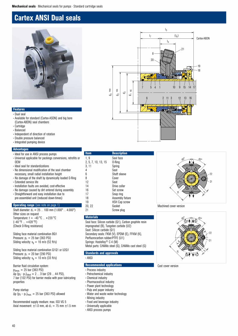
40
6 2 11 3 12 13 16
4 1 10 9 15 14 177 5
d 3
max
d 3
min
d 1
h6
d 2
l5
l7 ( l6)
l4
21
20
8
CARTEX–ABDN © EagleBurgmann
1918
45° 45°
d a
a2
22
21
sOUTIN
OUT IN
CARTEX– DN © EagleBurgmannVersion: Gussdeckel
Cast cover version
Cartex-ABDN
Machined cover version
45° 45°
22
21
sa2
d a
OUT IN
IN OUT
Version DrehdeckelCARTEX–ANSI © EagleBurgmann
Cartex ANSI Dual seals
Mechanical seals · Mechanical seals for pumps · Standard cartridge seals
Item Description1, 9 Seal face2, 5, 7, 10, 13, 15 O-Ring3, 11 Spring4 Seat6 Shaft sleeve8 Cover12 Seat14 Drive collar16 Set screw17 Snap ring18 Assembly fixture19 HSH Cap screw20, 22 Gasket21 Screw plug
MaterialsSeal face: Silicon carbide (Q1), Carbon graphite resin impregnated (B), Tungsten carbide (U2)Seat: Silicon carbide (Q1)Secondary seals: FKM (V), EPDM (E), FFKM (K), Perfluorocarbon rubber/PTFE (U1)Springs: Hastelloy® C-4 (M)Metal parts: CrNiMo steel (G), CrNiMo cast steel (G)
Standards and approvals• ANSI
Recommended applications• Process industry• Petrochemical industry• Chemical industry• Pharmaceutical industry• Power plant technology• Pulp and paper industry• Water and waste water technology• Mining industry• Food and beverage industry• Universally applicable• ANSI process pumps
Features• Dual seal• Available for standard (Cartex-ASDN) and big bore (Cartex-ABDN) seal chambers
• Cartridge• Balanced• Independent of direction of rotation• Double pressure balanced• Integrated pumping device
Advantages• Ideal for use in ANSI process pumps • Universal applicable for packings conversions, retrofits or OEM
• Ideal seal for standardizations• No dimensional modification of the seal chamber necessary, small radial installation height
• No damage of the shaft by dynamically loaded O-Ring• Extended service life• Installation faults are avoided, cost-effective• No damage caused by dirt entered during assembly• Straightforward and easy installation due to pre-assembled unit (reduced down-times)
Operating range (see note on page 1)Shaft diameter: d1 = 25 … 100 mm (1.000" … 4.000")Other sizes on requestTemperature: t = –40 °C … +220 °C (–40 °F … +428 °F)(Check O-Ring resistance)
Sliding face material combination BQ1Pressure: p1 = 25 bar (363 PSI)Sliding velocity: vg = 16 m/s (52 ft/s)
Sliding face material combination Q1Q1 or U2Q1Pressure: p1 = 20 bar (290 PSI)Sliding velocity: vg = 10 m/s (33 ft/s)
Barrier fluid circulation system:p3max. = 25 bar (363 PSI)Δp (p3 - p1)ideal = 2 … 3 bar (29 … 44 PSI), 7 bar (102 PSI) for barrier media with poor lubricating properties
Pump startup:Δp (p3 – p1)max. = 25 bar (363 PSI) allowed
Recommended supply medium: max. ISO VG 5Axial movement: ±1.0 mm, ab d1 = 75 mm ±1.5 mm
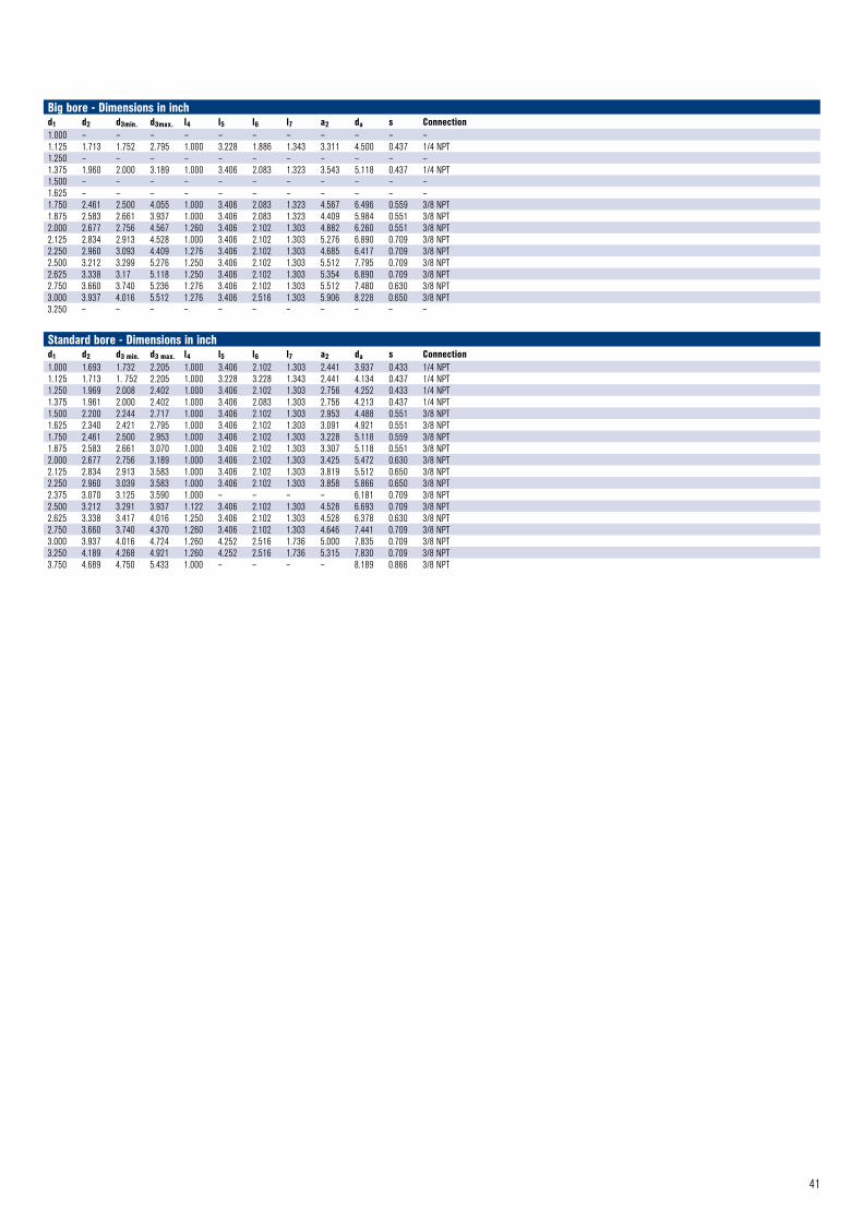
41
Big bore - Dimensions in inchd1 d2 d3min. d3max. l4 l5 l6 l7 a2 da s Connection1.000 – – – – – – – – – – –1.125 1.713 1.752 2.795 1.000 3.228 1.886 1.343 3.311 4.500 0.437 1/4 NPT1.250 – – – – – – – – – – –1.375 1.960 2.000 3.189 1.000 3.406 2.083 1.323 3.543 5.118 0.437 1/4 NPT1.500 – – – – – – – – – – –1.625 – – – – – – – – – – –1.750 2.461 2.500 4.055 1.000 3.406 2.083 1.323 4.567 6.496 0.559 3/8 NPT1.875 2.583 2.661 3.937 1.000 3.406 2.083 1.323 4.409 5.984 0.551 3/8 NPT2.000 2.677 2.756 4.567 1.260 3.406 2.102 1.303 4.882 6.260 0.551 3/8 NPT2.125 2.834 2.913 4.528 1.000 3.406 2.102 1.303 5.276 6.890 0.709 3/8 NPT2.250 2.960 3.093 4.409 1.276 3.406 2.102 1.303 4.685 6.417 0.709 3/8 NPT2.500 3.212 3.299 5.276 1.250 3.406 2.102 1.303 5.512 7.795 0.709 3/8 NPT2.625 3.338 3.17 5.118 1.250 3.406 2.102 1.303 5.354 6.890 0.709 3/8 NPT2.750 3.660 3.740 5.236 1.276 3.406 2.102 1.303 5.512 7.480 0.630 3/8 NPT3.000 3.937 4.016 5.512 1.276 3.406 2.516 1.303 5.906 8.228 0.650 3/8 NPT3.250 – – – – – – – – – – –
Standard bore - Dimensions in inchd1 d2 d3 min. d3 max. l4 l5 l6 l7 a2 da s Connection1.000 1.693 1.732 2.205 1.000 3.406 2.102 1.303 2.441 3.937 0.433 1/4 NPT1.125 1.713 1. 752 2.205 1.000 3.228 3.228 1.343 2.441 4.134 0.437 1/4 NPT1.250 1.969 2.008 2.402 1.000 3.406 2.102 1.303 2.756 4.252 0.433 1/4 NPT1.375 1.961 2.000 2.402 1.000 3.406 2.083 1.303 2.756 4.213 0.437 1/4 NPT1.500 2.200 2.244 2.717 1.000 3.406 2.102 1.303 2.953 4.488 0.551 3/8 NPT1.625 2.340 2.421 2.795 1.000 3.406 2.102 1.303 3.091 4.921 0.551 3/8 NPT1.750 2.461 2.500 2.953 1.000 3.406 2.102 1.303 3.228 5.118 0.559 3/8 NPT1.875 2.583 2.661 3.070 1.000 3.406 2.102 1.303 3.307 5.118 0.551 3/8 NPT2.000 2.677 2.756 3.189 1.000 3.406 2.102 1.303 3.425 5.472 0.630 3/8 NPT2.125 2.834 2.913 3.583 1.000 3.406 2.102 1.303 3.819 5.512 0.650 3/8 NPT2.250 2.960 3.039 3.583 1.000 3.406 2.102 1.303 3.858 5.866 0.650 3/8 NPT2.375 3.070 3.125 3.590 1.000 – – – – 6.181 0.709 3/8 NPT2.500 3.212 3.291 3.937 1.122 3.406 2.102 1.303 4.528 6.693 0.709 3/8 NPT2.625 3.338 3.417 4.016 1.250 3.406 2.102 1.303 4.528 6.378 0.630 3/8 NPT2.750 3.660 3.740 4.370 1.260 3.406 2.102 1.303 4.646 7.441 0.709 3/8 NPT3.000 3.937 4.016 4.724 1.260 4.252 2.516 1.736 5.000 7.835 0.709 3/8 NPT3.250 4.189 4.268 4.921 1.260 4.252 2.516 1.736 5.315 7.830 0.709 3/8 NPT3.750 4.689 4.750 5.433 1.000 – – – – 8.189 0.866 3/8 NPT
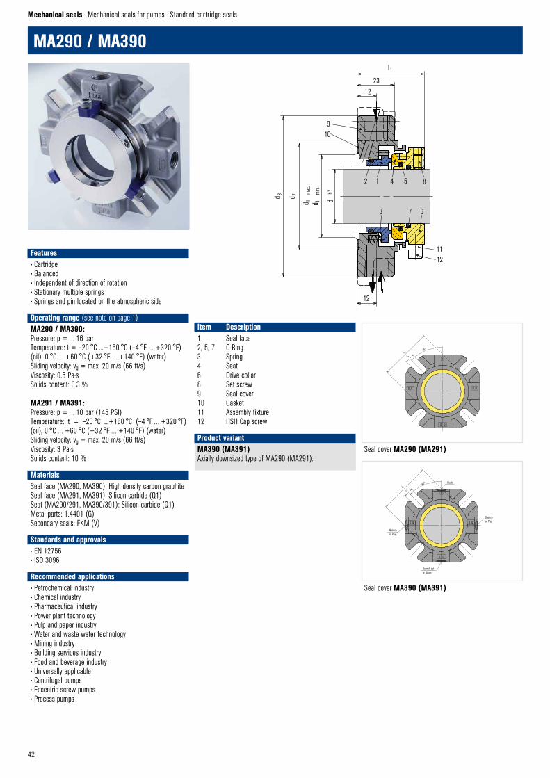
42
l1
2312
910
d 1
max
.d 1
m
in.
d h
7
2 1 4 5 8
3 7 6
1112
12
MA290 – MA291 © EagleBurgmann
d 2d 3
Flush45°l 6
l 7F
D ,Q
Quench or Plug
Quenchor PlugD ,Q
Quench outor Drain
D Q
MA390 – MA391 © EagleBurgmannSeal cover MA390 (MA391)
l 2l 3
45°
D ,Q D ,Q
D Q
F
MA290–MA291 © EagleBurgmannSeal cover MA290 (MA291)
MA290 / MA390
Mechanical seals · Mechanical seals for pumps · Standard cartridge seals
MA390 (MA391) Axially downsized type of MA290 (MA291).
Product variant
Item Description1 Seal face2, 5, 7 O-Ring3 Spring4 Seat 6 Drive collar8 Set screw9 Seal cover10 Gasket11 Assembly fixture12 HSH Cap screw
Features• Cartridge• Balanced• Independent of direction of rotation• Stationary multiple springs• Springs and pin located on the atmospheric side
Operating range (see note on page 1)MA290 / MA390:Pressure: p = … 16 barTemperature: t = –20 °C ...+160 °C (–4 °F … +320 °F) (oil), 0 °C … +60 °C (+32 °F … +140 °F) (water)Sliding velocity: vg = max. 20 m/s (66 ft/s)Viscosity: 0.5 Pa·sSolids content: 0.3 %
MA291 / MA391:Pressure: p = … 10 bar (145 PSI)Temperature: t = –20 °C ...+160 °C (–4 °F … +320 °F) (oil), 0 °C … +60 °C (+32 °F … +140 °F) (water)Sliding velocity: vg = max. 20 m/s (66 ft/s)Viscosity: 3 Pa·sSolids content: 10 %
MaterialsSeal face (MA290, MA390): High density carbon graphiteSeal face (MA291, MA391): Silicon carbide (Q1)Seat (MA290/291, MA390/391): Silicon carbide (Q1)Metal parts: 1.4401 (G)Secondary seals: FKM (V)
Standards and approvals• EN 12756• ISO 3096
Recommended applications• Petrochemical industry• Chemical industry• Pharmaceutical industry• Power plant technology• Pulp and paper industry• Water and waste water technology• Mining industry• Building services industry• Food and beverage industry• Universally applicable• Centrifugal pumps• Eccentric screw pumps• Process pumps
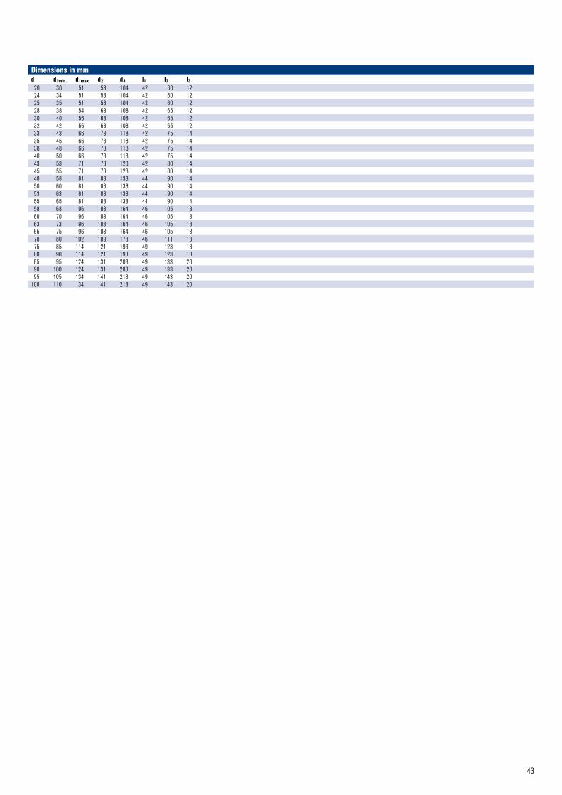
43
Dimensions in mmd d1min. d1max. d2 d3 l1 l2 l320 30 51 58 104 42 60 1224 34 51 58 104 42 60 1225 35 51 58 104 42 60 1228 38 54 63 108 42 65 1230 40 56 63 108 42 65 1232 42 56 63 108 42 65 1233 43 66 73 118 42 75 1435 45 66 73 118 42 75 1438 48 66 73 118 42 75 1440 50 66 73 118 42 75 1443 53 71 78 128 42 80 1445 55 71 78 128 42 80 1448 58 81 88 138 44 90 1450 60 81 88 138 44 90 1453 63 81 88 138 44 90 1455 65 81 88 138 44 90 1458 68 96 103 164 46 105 1860 70 96 103 164 46 105 1863 73 96 103 164 46 105 1865 75 96 103 164 46 105 1870 80 102 109 178 46 111 1875 85 114 121 193 49 123 1880 90 114 121 193 49 123 1885 95 124 131 208 49 133 2090 100 124 131 208 49 133 2095 105 134 141 218 49 143 20
100 110 134 141 218 49 143 20
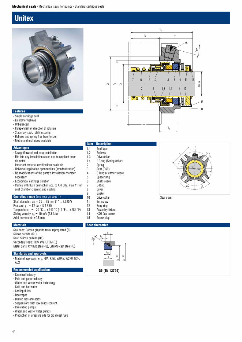
44
G6 (EN 12756)
Seal cover
Unitex
Mechanical seals · Mechanical seals for pumps · Standard cartridge seals
Seat alternative
7 6 5 3 4 11 12
2 8 10
d N
h6
13
14
l4
l1
l3 l2
15
20°
d 9 d 3 d 2
Unitex © EagleBurgmann
1.2 1.1
9 1.3 1.4
l28
l10
d7
H8
d6
H11
l6 l5
20°
G6 (M32N4) © EagleBurgmann
45° 45°
Unitex © EagleBurgmann
s
t
a
da
Item Description1.1 Seal face1.2 Bellows1.3 Drive collar1.4 “L”-ring (Spring collar)2 Spring3 Seat (G60)4 O-Ring or corner sleeve5 Spacer ring6 Shaft sleeve7 O-Ring8 Cover9 Gasket10 Drive collar11 Set screw12 Snap ring13 Assembly fixture14 HSH Cap screw15 Screw plug
Features• Single cartridge seal• Elastomer bellows• Unbalanced• Independent of direction of rotation• Stationary seat, rotating spring• Bellows and spring free from torsion• Metric and inch sizes available
Advantages• Straightforward and easy installation• Fits into any installation space due to smallest outer diameter
• Important material certifications available• Universal application opportunities (standardization) • No modifications of the pump's installation chamber necessary
• Economical cartridge solution• Comes with flush connection acc. to API 682, Plan 11 for seal chamber cleaning and cooling
Operating range (see note on page 1)Shaft diameter: dN = 25 … 75 mm (1" … 2.625")Pressure: p1 = 12 bar (174 PSI)Temperature: t = –20 °C … +140 °C (–4 °F … +284 °F)Sliding velocity: vg = 10 m/s (33 ft/s)Axial movement: ±0.5 mm
MaterialsSeal face: Carbon graphite resin impregnated (B), Silicon carbide (Q1)Seat: Silicon carbide (Q1)Secondary seals: FKM (V), EPDM (E)Metal parts: CrNiMo steel (G), CrNiMo cast steel (G)
Standards and approvals• Material approvals: e. g. FDA, KTW, WRAS, W270, NSF, ACS
Recommended applications• Chemical industry• Pulp and paper industry• Water and waste water technology • Cold and hot water• Cooling fluids• Beverages• Diluted lyes and acids• Suspensions with low solids content• Circulating pumps• Water and waste water pumps• Production of pressure oils for bio diesel fuels
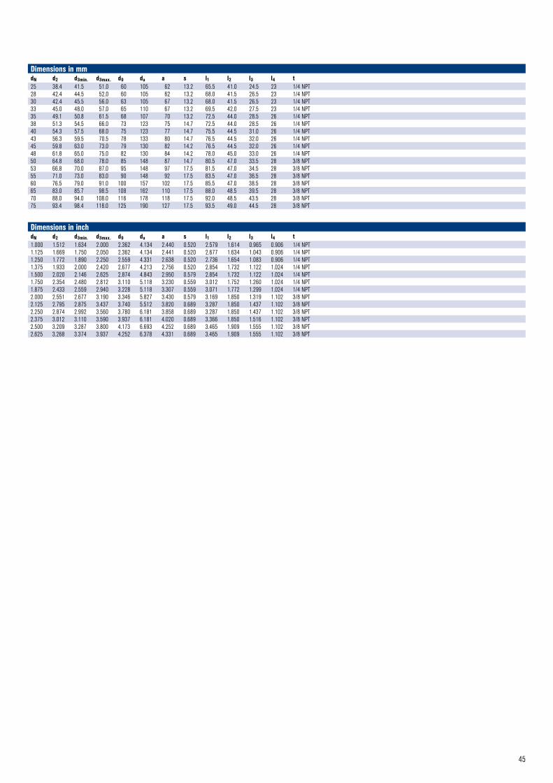
45
Dimensions in mmdN d2 d3min. d3max. d9 da a s l1 l2 l3 l4 t25 38.4 41.5 51.0 60 105 62 13.2 65.5 41.0 24.5 23 1/4 NPT28 42.4 44.5 52.0 60 105 62 13.2 68.0 41.5 26.5 23 1/4 NPT30 42.4 45.5 56.0 63 105 67 13.2 68.0 41.5 26.5 23 1/4 NPT33 45.0 48.0 57.0 65 110 67 13.2 69.5 42.0 27.5 23 1/4 NPT35 49.1 50.8 61.5 68 107 70 13.2 72.5 44.0 28.5 26 1/4 NPT38 51.3 54.5 66.0 73 123 75 14.7 72.5 44.0 28.5 26 1/4 NPT40 54.3 57.5 68.0 75 123 77 14.7 75.5 44.5 31.0 26 1/4 NPT43 56.3 59.5 70.5 78 133 80 14.7 76.5 44.5 32.0 26 1/4 NPT45 59.8 63.0 73.0 79 130 82 14.2 76.5 44.5 32.0 26 1/4 NPT48 61.8 65.0 75.0 82 130 84 14.2 78.0 45.0 33.0 26 1/4 NPT50 64.8 68.0 78.0 85 148 87 14.7 80.5 47.0 33.5 28 3/8 NPT53 66.8 70.0 87.0 95 148 97 17.5 81.5 47.0 34.5 28 3/8 NPT55 71.0 73.0 83.0 90 148 92 17.5 83.5 47.0 36.5 28 3/8 NPT60 76.5 79.0 91.0 100 157 102 17.5 85.5 47.0 38.5 28 3/8 NPT65 83.0 85.7 98.5 108 162 110 17.5 88.0 48.5 39.5 28 3/8 NPT70 88.0 94.0 108.0 116 178 118 17.5 92.0 48.5 43.5 28 3/8 NPT75 93.4 98.4 118.0 125 190 127 17.5 93.5 49.0 44.5 28 3/8 NPT
Dimensions in inchdN d2 d3min. d3max. d9 da a s l1 l2 l3 l4 t1.000 1.512 1.634 2.000 2.362 4.134 2.440 0.520 2.579 1.614 0.965 0.906 1/4 NPT1.125 1.669 1.750 2.050 2.362 4.134 2.441 0.520 2.677 1.634 1.043 0.906 1/4 NPT1.250 1.772 1.890 2.250 2.559 4.331 2.638 0.520 2.736 1.654 1.083 0.906 1/4 NPT1.375 1.933 2.000 2.420 2.677 4.213 2.756 0.520 2.854 1.732 1.122 1.024 1/4 NPT1.500 2.020 2.146 2.625 2.874 4.843 2.950 0.579 2.854 1.732 1.122 1.024 1/4 NPT1.750 2.354 2.480 2.812 3.110 5.118 3.230 0.559 3.012 1.752 1.260 1.024 1/4 NPT1.875 2.433 2.559 2.940 3.228 5.118 3.307 0.559 3.071 1.772 1.299 1.024 1/4 NPT2.000 2.551 2.677 3.190 3.346 5.827 3.430 0.579 3.169 1.850 1.319 1.102 3/8 NPT2.125 2.795 2.875 3.437 3.740 5.512 3.820 0.689 3.287 1.850 1.437 1.102 3/8 NPT2.250 2.874 2.992 3.560 3.780 6.181 3.858 0.689 3.287 1.850 1.437 1.102 3/8 NPT2.375 3.012 3.110 3.590 3.937 6.181 4.020 0.689 3.366 1.850 1.516 1.102 3/8 NPT2.500 3.209 3.287 3.800 4.173 6.693 4.252 0.689 3.465 1.909 1.555 1.102 3/8 NPT2.625 3.268 3.374 3.937 4.252 6.378 4.331 0.689 3.465 1.909 1.555 1.102 3/8 NPT

46
d 3 d 2 d 1
3 7 6 15 4 16 8 11 12
2 1 5 9 10
l1
l2 l3
l4
13
14
Mtex © EagleBurgmann45° 45°
A
B B
d a
a1 s
BB
Mtex © EagleBurgmannSeal cover
Mtex Single seals
Mechanical seals · Mechanical seals for pumps · Standard cartridge seals
Features• Single seal• Cartridge• Balanced• Independent of direction of rotation• Metal bellows• Single seal with quench and lip seal (-QN) or throttle ring (-TN)
• Version available with multipoint injection ring (-QNM, -TNM)
• Supply connections for flush (A) and quench (B)
Advantages• Ideal seal for standardizations• Universal applicable for packings conversions, retrofits or OEM
• Suitable for high temperature• No dimensional modification of the seal chamber necessary, small radial installation height
• Trouble-free running due to bellows unit with vibration dampers (essential in case of dry-running)
• No dynamically loaded O-Ring• Self cleaning effect of the bellows• Installation faults are avoided, cost-effective• No damage caused by dirt entered during assembly• Straightforward and easy installation due to preassembled unit (reduced down-times)
• Individual adaptation to pump design possible
Operating range (see note on page 1)Shaft diameter: d1 = 25 … 80 mm (1" … 3.15")Temperature: t* = –40 °C … +220 °C (–40 °F … +428 °F)Pressure: p = 25 bar (363 PSI)Sliding velocity: vg = 20 m/s (66 ft/s)* Operating limits of O-Rings to be observed
MaterialsSeal face: Carbon graphite antimony impregnated (A), Silicon carbide (Q1)Seat: Silicon carbide (Q1)Secondary seals: FKM (V), EPDM (E), FFKM (K)Bellows: Inconel® 718 (M6)Metal parts: CrNiMo steel (G), Duplex (G1)Throttle ring: PTFE carbon graphite reinforced (T12)Lip seal: NBR (P), PTFE carbon reinforced (T3)
Item Description1 Bellows unit2, 5, 7 O-Ring3, 11 Set screw4 Seat6 Shaft sleeve8 Cover9 Lip seal or throttle ring10 Drive collar12 Snap ring13 Assembly fixture14 HSH Cap screw15 Gasket16 Screw plug
Recommended applications• Process industry• Chemical industry• Hot media• Cold media• Highly viscous media• Pumps• Special rotating equipment
Mtex-QN
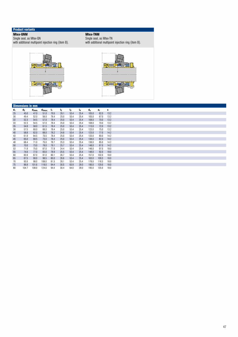
47
B
Mtex – QNM © EagleBurgmann
B
Mtex – TNM © EagleBurgmann
Mtex-QNMSingle seal, as Mtex-QN with additional multipoint injection ring (item B).
Mtex-TNMSingle seal, as Mtex-TN with additional multipoint injection ring (item B).
Product variants
Dimensions in mmd1 d2 d3min. d3max. l1 l2 l3 l4 da a1 s 25 45.0 47.0 51.0 79.5 26.1 53.4 25.4 105.0 62.0 13.230 49.4 52.0 56.0 78.4 25.0 53.4 25.4 105.0 67.0 13.232 52.3 54.5 57.0 78.4 25.0 53.4 25.4 108.0 70.0 13.233 52.3 54.5 57.0 78.4 25.0 53.4 25.4 108.0 70.0 13.235 54.8 58.0 61.5 78.4 25.0 53.4 25.4 113.0 72.0 13.238 57.5 60.0 66.0 78.4 25.0 53.4 25.4 123.0 75.0 13.240 58.8 62.0 68.0 78.2 24.8 53.4 25.4 123.0 77.0 14.243 61.9 64.5 70.5 78.4 25.0 53.4 25.4 133.0 80.0 14.245 65.0 68.5 73.0 78.4 25.0 53.4 25.4 138.0 82.0 14.248 68.4 71.0 75.0 78.7 25.3 53.4 25.4 138.0 85.0 14.250 70.0 73.0 78.0 79.1 25.7 53.4 25.4 148.0 87.0 14.253 71.9 75.0 87.0 77.8 24.4 53.4 25.4 148.0 97.0 18.055 74.6 77.0 83.0 78.9 25.5 53.4 25.4 148.0 92.0 18.060 83.9 87.0 91.0 80.1 26.7 53.4 25.4 157.0 102.0 18.065 87.5 90.0 98.5 80.0 26.6 53.4 25.4 163.0 109.3 18.070 93.0 98.0 108.0 81.5 28.1 53.4 25.4 178.0 118.3 18.075 96.8 101.6 118.0 94.4 30.5 63.9 28.0 190.0 129.0 18.080 104.7 108.0 124.0 94.4 30.4 64.0 28.0 195.0 135.0 18.0
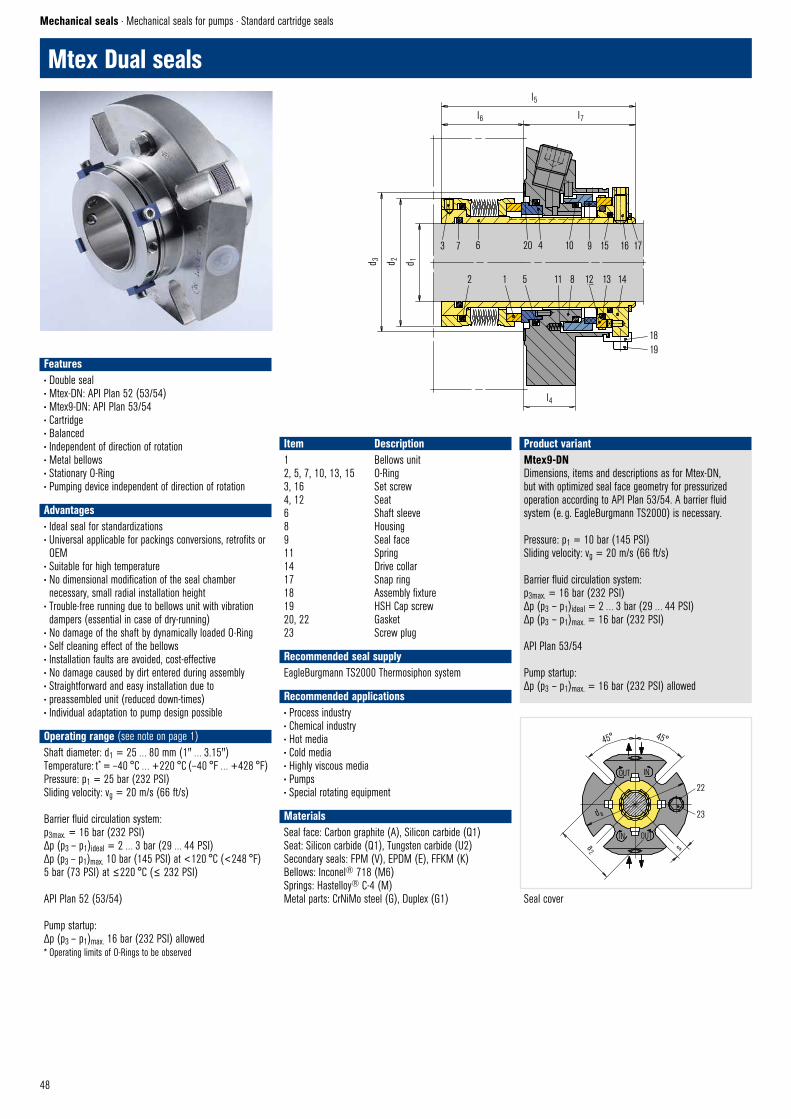
48
3 7 6 20 4 10 9 15 16 17
2 1 5 11 8 12 13 14
d 3 d 2 d 1
l6
l5
l7
l4
1819
Mtex – DN © EagleBurgmann
22
23
sa2
d a
45° 45°
OUT IN
IN OUT
Seal cover
Mtex Dual seals
Mechanical seals · Mechanical seals for pumps · Standard cartridge seals
Mtex9-DNDimensions, items and descriptions as for Mtex-DN, but with optimized seal face geometry for pressurized operation according to API Plan 53/54. A barrier fluid system (e. g. EagleBurgmann TS2000) is necessary.
Pressure: p1 = 10 bar (145 PSI)Sliding velocity: vg = 20 m/s (66 ft/s)
Barrier fluid circulation system:p3max. = 16 bar (232 PSI)Δp (p3 – p1)ideal = 2 … 3 bar (29 … 44 PSI)Δp (p3 – p1)max. = 16 bar (232 PSI)
API Plan 53/54
Pump startup:Δp (p3 – p1)max. = 16 bar (232 PSI) allowed
Product variant
Features• Double seal• Mtex-DN: API Plan 52 (53/54)• Mtex9-DN: API Plan 53/54• Cartridge• Balanced• Independent of direction of rotation• Metal bellows• Stationary O-Ring • Pumping device independent of direction of rotation • Advantages• Ideal seal for standardizations• Universal applicable for packings conversions, retrofits or OEM
• Suitable for high temperature• No dimensional modification of the seal chamber necessary, small radial installation height
• Trouble-free running due to bellows unit with vibration dampers (essential in case of dry-running)
• No damage of the shaft by dynamically loaded O-Ring• Self cleaning effect of the bellows• Installation faults are avoided, cost-effective• No damage caused by dirt entered during assembly• Straightforward and easy installation due to • preassembled unit (reduced down-times) • Individual adaptation to pump design possible
Operating range (see note on page 1)Shaft diameter: d1 = 25 … 80 mm (1" … 3.15") Temperature: t* = –40 °C … +220 °C (–40 °F … +428 °F) Pressure: p1 = 25 bar (232 PSI) Sliding velocity: vg = 20 m/s (66 ft/s)
Barrier fluid circulation system: p3max. = 16 bar (232 PSI) Δp (p3 – p1)ideal = 2 … 3 bar (29 … 44 PSI) Δp (p3 – p1)max. 10 bar (145 PSI) at <120 °C (<248 °F) 5 bar (73 PSI) at ≤220 °C (≤ 232 PSI)
API Plan 52 (53/54)
Pump startup: Δp (p3 – p1)max. 16 bar (232 PSI) allowed
* Operating limits of O-Rings to be observed
Item Description1 Bellows unit2, 5, 7, 10, 13, 15 O-Ring3, 16 Set screw4, 12 Seat6 Shaft sleeve8 Housing9 Seal face11 Spring14 Drive collar17 Snap ring18 Assembly fixture19 HSH Cap screw20, 22 Gasket23 Screw plug
Recommended seal supplyEagleBurgmann TS2000 Thermosiphon system
Recommended applications• Process industry• Chemical industry• Hot media• Cold media• Highly viscous media• Pumps• Special rotating equipment
MaterialsSeal face: Carbon graphite (A), Silicon carbide (Q1)Seat: Silicon carbide (Q1), Tungsten carbide (U2)Secondary seals: FPM (V), EPDM (E), FFKM (K)Bellows: Inconel® 718 (M6)Springs: Hastelloy® C-4 (M)Metal parts: CrNiMo steel (G), Duplex (G1)

49
Dimensions in mmd1 d2 d3min. d3max. l4 l5 l6 l7 da a2 s 25 45.0 47.0 51.0 25.4 87.0 33.6 53.4 105.0 62.0 13.230 49.4 52.0 56.0 25.4 86.5 33.1 53.4 105.0 67.0 13.232 52.3 54.5 57.0 25.4 86.5 33.1 53.4 108.0 70.0 13.233 52.3 54.5 57.0 25.4 86.5 33.1 53.4 108.0 70.0 13.235 54.8 58.0 61.5 25.4 86.5 33.1 53.4 113.0 72.0 13.238 57.5 60.0 66.0 25.4 86.5 33.1 53.4 123.0 75.0 14.040 58.8 62.0 68.0 25.4 86.3 32.9 53.4 123.0 77.0 14.243 61.9 64.5 70.5 25.4 86.5 33.1 53.4 133.0 80.0 14.245 65.0 68.5 73.0 25.4 86.5 33.1 53.4 138.0 82.0 14.248 68.4 71.0 75.0 25.4 86.8 33.4 53.4 138.0 85.0 14.250 70.0 73.0 78.0 25.4 87.2 33.8 53.4 148.0 87.0 14.253 71.9 75.0 87.0 25.4 87.4 34.0 53.4 148.0 97.0 18.055 74.6 77.0 83.0 25.4 87.0 33.6 53.4 148.0 92.0 18.060 83.9 87.0 91.0 25.4 88.2 34.8 53.4 157.0 102.0 18.065 87.5 90.0 98.5 25.4 88.1 34.7 53.4 163.0 109.3 18.070 93.0 98.0 108.0 25.4 89.6 36.2 53.4 178.0 118.3 18.075 96.8 101.6 118.0 28.0 107.4 43.5 63.9 190.0 129.0 18.080 104.7 108.0 124.0 28.0 106.8 42.9 63.9 195.0 135.0 18.0
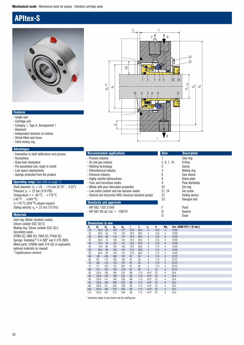
50
APItex-S
Mechanical seals · Mechanical seals for pumps · Standard cartridge seals
Features• Single seal• Cartridge unit• Category 1, Type A, Arrangement 1• Balanced• Independent direction of rotation• Shrink-fitted seal faces• Solid mating ring
Advantages• Insensitive to shaft deflections and process• fluctuations• Good heat dissipation• Pre-assembled unit, ready to install• Low space requirements• Springs protected from the product
Operating range (see note on page 1)Shaft diameter: d1 = 20 … 110 mm (0.79" … 4.33")Pressure: p1 = 22 bar (319 PSI)Temperature: t = -40 °C … +176 °C(-40 °F … +349 °F)(>176 °C (349 °F) please inquire)Sliding velocity: vg = 23 m/s (75 ft/s)
MaterialsSeal ring: Blister resistant carbon,Silicon carbide SSiC (Q12)Mating ring: Silicon carbide SSiC (Q1)Secondary seals:EPDM (E), NBR (P), FKM (V), FFKM (K)Springs: Hastelloy® C-4 (M)* and C-276 (M5)Metal parts: CrNiMo steel 316 (G) or equivalent,optional materials on request.* EagleBurgmann standard
Recommended applications• Process industry• Oil and gas industry• Refining technology• Petrochemical industry• Chemical industry• Highly volatile hydrocarbons• Toxic and hazardous media• Media with poor lubrication properties• Low solids content and low abrasive media• Vertical and horizontal ANSI chemical standard pumps
Standards and approvals• API 682 / ISO 21049• API 682 4th ed. Cat. 1 - 1CW-FX
Item Description1 Seal ring2, 5, 7, 16 O-Ring3 Spring4 Mating ring6 Seal sleeve8 Gland plate9 Flow distributor20 Set ring21, 24 Set screw22 Setting device23 Hexagon bolt
F FlushQ QuenchD Drain
Dimensions in mmd1 d2 d3 d4 d5 l l1 l2 d Qty. Acc. ASME B73.1 (h min.)20 50.4 58 105 127 70.5 66.5 4 13.5 4 19.0525 55.4 63 110 132 70.5 66.5 4 13.5 4 19.0530 60.4 68 115 137 70.5 66.5 4 13.5 4 19.0535 65.4 73 120 142 70.5 66.5 4 13.5 4 19.0540 70.4 78 125 147 70.5 66.5 4 13.5 4 19.0545 75.4 83 135 162 70.5 66.5 4 17.5 4 19.0550 80.4 88 140 167 72.5 68.5 4 17.5 4 19.0555 85.4 93 145 172 72.5 68.5 4 17.5 4 19.0560 96 105 160 187 87 83 4 17.5 4 22.2265 101 110 165 192 87 83 4 17.5 4 22.2270 106 115 170 197 87 83 4 17.5 4 22.2275 111 120 175 202 87 83 4 17.5 4 22.2280 116 125 185 218 87 83 4 22 4 22.2285 123.5 136 190 223 86 71.5 14.5* 22 4 25.485 123.5 136 190 223 86 71.5 14.5* 22 4 25.490 128.5 141 195 228 86 71.5 14.5* 22 4 25.495 133.5 146 200 233 86 71.5 14.5* 22 4 25.4
100 138.5 151 205 238 86 71.5 14.5* 22 4 25.4105 143.5 156 210 243 86 71.5 14.5* 22 4 25.4110 152.5 161 215 248 86 71.5 14.5* 22 4 25.4
* Immersion depth of seal sleeve into the stuffing box.
16 6 3 8 9
7 2 1 4 5 20 24
21
2322
APITEX–SC © EagleBurgmann
D
d 3 H7
d 2 d 1 h
6
d 4 d 5
Q
l1 l2
(h)
d
l
F
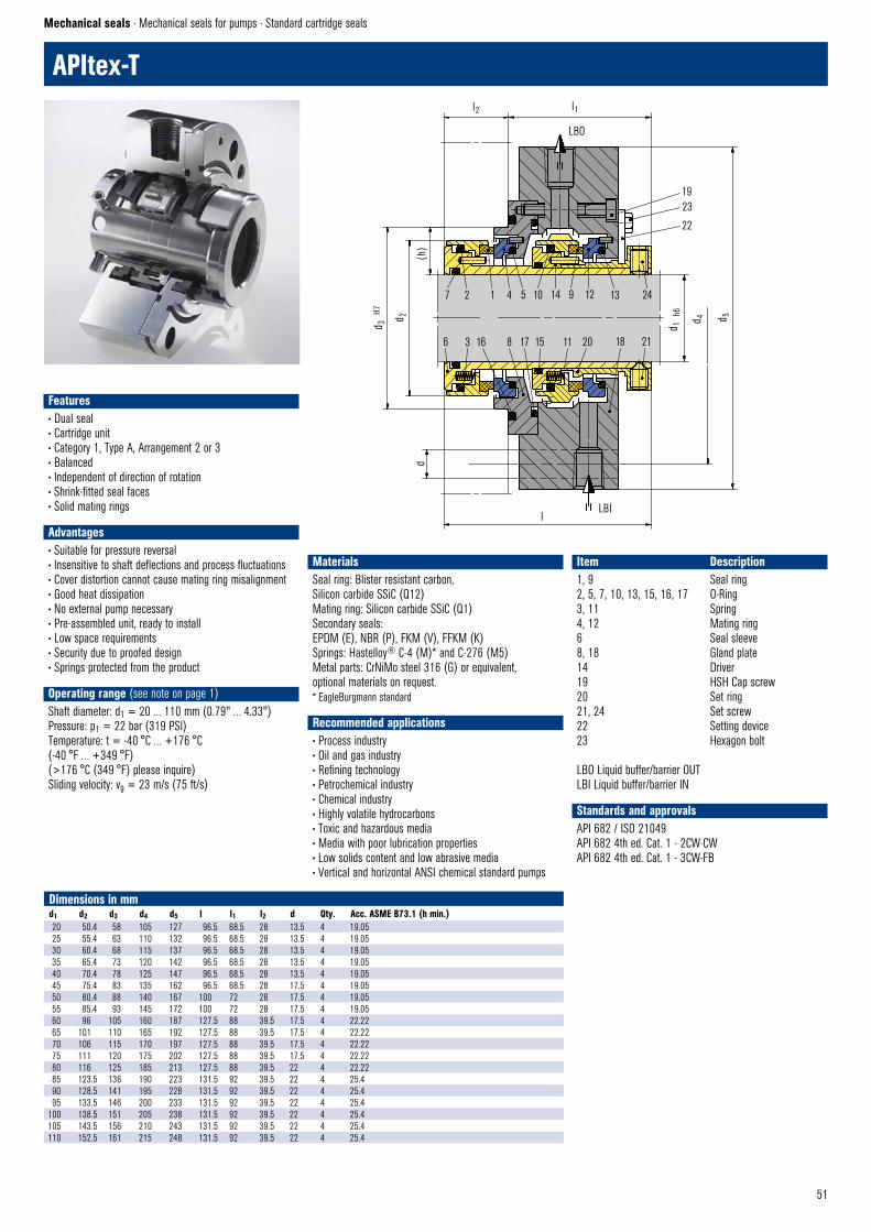
51
Dimensions in mmd1 d2 d3 d4 d5 l l1 l2 d Qty. Acc. ASME B73.1 (h min.)20 50.4 58 105 127 96.5 68.5 28 13.5 4 19.0525 55.4 63 110 132 96.5 68.5 28 13.5 4 19.0530 60.4 68 115 137 96.5 68.5 28 13.5 4 19.0535 65.4 73 120 142 96.5 68.5 28 13.5 4 19.0540 70.4 78 125 147 96.5 68.5 28 13.5 4 19.0545 75.4 83 135 162 96.5 68.5 28 17.5 4 19.0550 80.4 88 140 167 100 72 28 17.5 4 19.0555 85.4 93 145 172 100 72 28 17.5 4 19.0560 96 105 160 187 127.5 88 39.5 17.5 4 22.2265 101 110 165 192 127.5 88 39.5 17.5 4 22.2270 106 115 170 197 127.5 88 39.5 17.5 4 22.2275 111 120 175 202 127.5 88 39.5 17.5 4 22.2280 116 125 185 213 127.5 88 39.5 22 4 22.2285 123.5 136 190 223 131.5 92 39.5 22 4 25.490 128.5 141 195 228 131.5 92 39.5 22 4 25.495 133.5 146 200 233 131.5 92 39.5 22 4 25.4
100 138.5 151 205 238 131.5 92 39.5 22 4 25.4105 143.5 156 210 243 131.5 92 39.5 22 4 25.4110 152.5 161 215 248 131.5 92 39.5 22 4 25.4
APItex-T
Mechanical seals · Mechanical seals for pumps · Standard cartridge seals
Features• Dual seal• Cartridge unit• Category 1, Type A, Arrangement 2 or 3• Balanced• Independent of direction of rotation• Shrink-fitted seal faces• Solid mating rings
Advantages• Suitable for pressure reversal• Insensitive to shaft deflections and process fluctuations• Cover distortion cannot cause mating ring misalignment• Good heat dissipation• No external pump necessary• Pre-assembled unit, ready to install• Low space requirements• Security due to proofed design• Springs protected from the product
Operating range (see note on page 1)Shaft diameter: d1 = 20 … 110 mm (0.79" … 4.33")Pressure: p1 = 22 bar (319 PSI)Temperature: t = -40 °C … +176 °C(-40 °F … +349 °F)(>176 °C (349 °F) please inquire)Sliding velocity: vg = 23 m/s (75 ft/s)
Item Description1, 9 Seal ring2, 5, 7, 10, 13, 15, 16, 17 O-Ring3, 11 Spring4, 12 Mating ring6 Seal sleeve8, 18 Gland plate14 Driver19 HSH Cap screw20 Set ring21, 24 Set screw22 Setting device23 Hexagon bolt
LBO Liquid buffer/barrier OUTLBI Liquid buffer/barrier IN
Standards and approvalsAPI 682 / ISO 21049API 682 4th ed. Cat. 1 - 2CW-CWAPI 682 4th ed. Cat. 1 - 3CW-FB
MaterialsSeal ring: Blister resistant carbon,Silicon carbide SSiC (Q12)Mating ring: Silicon carbide SSiC (Q1)Secondary seals:EPDM (E), NBR (P), FKM (V), FFKM (K)Springs: Hastelloy® C-4 (M)* and C-276 (M5)Metal parts: CrNiMo steel 316 (G) or equivalent,optional materials on request.* EagleBurgmann standard
Recommended applications• Process industry• Oil and gas industry• Refining technology• Petrochemical industry• Chemical industry• Highly volatile hydrocarbons• Toxic and hazardous media• Media with poor lubrication properties• Low solids content and low abrasive media• Vertical and horizontal ANSI chemical standard pumps
7 2 1 4 5 10 14 9 12 13 24
8 17 15 11 20 18 216 3 16
1923
22
APITEX–TC © EagleBurgmann
LBI
d
d 3 H7
d 2
d 1 h
6
d 4
d 1 h
6
d 5
LBO
l1 l2
l
(h)

52
MG1
MG12 Dimensions, items and designations same as for MG1, but with an extended bellows tail to achieve the fitting length I1k according to EN 12756 in combination with seat G6 or G60 (da exceeds EN 12756).
MG1S20Dimensions, items and designations same as for MG1, but with an extended bellows tail to achieve the special fitting length I1S in combination with seat G50.
Product variantsMG13Dimensions, items and designations same as for MG1, but with an extended bellows tail to achieve the fitting length I1N according to EN 12756 in combination with seat G6 or G60 (da exceeds EN 12756).
RMG12Identical to MG12, but with a special bellows surface on the shaft side. For use in hot water pumps up to 120 °C(248 °F) and 25 bar (363 ft/s) or 140 °C (284 °F)and 16 bar (232 PSI). Only in combination with seatG606 (d1 = 12 … 38 mm) (0.47" … 1.50").Seal face: Tungsten Carbide (U3)Seat G606: Carbon graphite resin impregnated (B)
MG13 © EagleBurgmann
d s
min
l2l1N
MG1S20 © EagleBurgmann
l3l1S
d m m
in
MG12
MG1S20
MG13
MG1
Mechanical seals · Mechanical seals for pumps · Elastomer bellows seals
MG12 © EagleBurgmann
d s
min
l1
l1k
Features• For plain shafts• Single and dual seal• Elastomer bellows rotating• Unbalanced• Independent of direction of rotation• No torsion on bellows
Advantages• Shaft protection over the entire seal length• Protection of the seal face during installation due to special bellows design
• Insensitive to shaft deflections due to large axial movement ability
• Universal application opportunities• Important material certifications available• High flexibility due to wide offer on materials• Suitable for low-end sterile applications• Special design for hot water pumps (RMG12) available• Dimension adaptions and additional seats available
Operating range (see note on page 1)Shaft diameter: d1 = 10 … 100 mm (0.39" … 3.94")Pressure: p1 = 16 bar (230 PSI),vacuum … 0,5 bar (7.25 PSI), up to 1 bar (14.5 PSI) with seat lockingTemperature: t = – 20 °C … +140 °C (– 4 °F … +284 °F)Sliding velocity: vg = 10 m/s (33 ft/s)Axial movement: ±2.0 mm
Recommended applications• Process industry• Chemical industry• Pulp and paper industry• Water and waste water technology• Food and beverage industry• Sugar industry• Oil applications• Water, waste water, slurries (up to 5 % by weight)• Pulp (up to 4 % otro)• Latex• Dairies, beverages• Sulfide slurries• Chemicals• Oils• Chemical standard pumps• Helical screw pumps• Stock pumps• Circulating pumps• Submersible pumps• Water and waster water pumps
MaterialsSeal face: Carbon graphite antimony impregnated (A), Carbon graphite resin impregnated (B), Silicon carbide (Q1), Tungsten carbide (U3) Seat: Silicon carbide (Q1, Q2), Tungsten carbide (U3), Special cast CrMo steel (S), Aluminium oxide (V)Elastomer: NBR (P), EPDM (E), FKM (V), HNBR (X4)Metal parts: CrNiMo steel (G), Hastelloy® C-4 (M)
Standards and approvals• Various material approvals e.g. FDA, WRAS, KTW, ACS, W270, NSF available (depending on type and material combinations). Please inquire!
• EN 12756 (MG12, MG13)
Item Part no. to DIN 24250 Description1.1 472 Seal face1.2 481 Bellows1.3 484.2 “L”-ring (spring collar)1.4 484.1 “L”-ring (spring collar)1.5 477 Spring2 475 Seat3 412 O-Ring or cup rubber
1.2 1.5 1.1 2 3
1.3 1.4
d ST
min
d b m
in
d a d 1 h8 d 3
l
MG1 © EagleBurgmann

53
G4 G9 EN 12756 G6 EN 12756
G60 EN 12756
G606 EN 12756 (for RMG12 only)
G50 Euro standard
Seat alternatives
30°
l16l15 R
G4 © EagleBurgmann
l12
l14
d 11
+0,1
d 12
H7
d 7
H8
d 6
H11
l6l5
20°
G9 © EagleBurgmann
5
l9l8
d8
l7 +0,5
l28
l10
d7
H8
d6
H11
l6 l5
20°
G6 (M32N4) © EagleBurgmann
20°
l6l5
l28
l10
d 6 H1
1
d 7
H8
G606 © EagleBurgmann
d 7
H8
d 6
H11
l6l5
20°
G60–MG1 © EagleBurgmann
l28
l17
l29
d 14
d 16
±0,
05
R1
G50 (MG1S20) © EagleBurgmann
Dimensions in mmd1 d3 d6 d7 d8 d11 d12 d14 d16 da db* dm* ds* dST l l1 l1k l1N l1S l2 l3 l5 l6 l7 l8 l9 l10 l12 l14 l15 l16 l17 l28 l29 R10 15.7 17 21 3 15.5 19.2 11.0 24.60 22.5 20.5 18 18 24 14.5 25.9 32.5 40 34.0 33.4 25 1.5 4 8.5 17.5 10.0 7.5 7.5 6.6 1.2 3.8 7.5 6.6 9.0 1.212 17.7 19 23 3 17.5 21.6 13.5 27.80 25.0 22.5 20 20 26 15.0 25.9 32.5 40 34.0 33.4 25 1.5 4 8.5 17.5 10.0 7.5 6.5 5.6 1.2 3.8 7.5 6.6 9.0 1.214 19.7 21 25 3 20.5 24.6 17.0 30.95 28.5 26.5 22 22 30 17.0 28.4 35.0 40 35.5 33.4 25 1.5 4 8.5 17.5 10.0 7.5 6.5 5.6 1.2 3.8 9.0 6.6 10.5 1.215 20.8 – – – 20.5 24.6 17.0 30.95 28.5 26.5 22 22 30 17.0 28.4 – – 35.5 33.4 25 – – – – – – 7.5 6.6 1.2 3.8 9.0 – 10.5 1.216 21.0 23 27 3 22.0 28.0 17.0 30.95 28.5 26.5 22 22 30 17.0 28.4 35.0 40 35.5 33.4 25 1.5 4 8.5 17.5 10.0 7.5 8.5 7.5 1.5 5.0 9.0 6.6 10.5 1.518 23.7 27 33 3 24.0 30.0 20.0 34.15 32.0 29.0 29 26 33 19.5 30.0 37.5 45 35.5 37.5 25 2.0 5 9.0 19.5 11.5 8.5 9.0 8.0 1.5 5.0 9.0 7.5 10.5 1.519 26.7 – – – – – 20.0 34.15 37.0 33.0 33 28 38 21.5 30.0 – – 35.5 37.5 25 – – – – – – – – – – 9.0 – 10.5 –20 26.7 29 35 3 29.5 35.0 21.5 35.70 37.0 33.0 33 28 38 21.5 30.0 37.5 45 35.5 37.5 25 2.0 5 9.0 19.5 11.5 8.5 8.5 7.5 1.5 5.0 9.0 7.5 10.5 1.522 27.7 31 37 3 29.5 35.0 23.0 37.30 37.0 33.0 33 28 38 21.5 30.0 37.5 45 35.5 37.5 25 2.0 5 9.0 19.5 11.5 8.5 8.5 7.5 1.5 5.0 9.0 7.5 10.5 1.524 31.2 33 39 3 32.0 38.0 26.5 40.50 42.5 38.0 38 32 44 22.5 32.5 40.0 50 35.5 42.5 25 2.0 5 9.0 19.5 11.5 8.5 8.5 7.5 1.5 5.0 9.0 7.5 10.5 1.525 31.2 34 40 3 32.0 38.0 26.5 40.50 42.5 38.0 38 32 44 23.0 32.5 40.0 50 35.5 42.5 25 2.0 5 9.0 19.5 11.5 8.5 8.5 7.5 1.5 5.0 9.0 7.5 10.5 1.528 35.0 37 43 3 36.0 42.0 29.5 47.65 49.0 44.0 37 37 50 26.5 35.0 42.5 50 45.0 42.5 33 2.0 5 9.0 19.5 11.5 8.5 10.0 9.0 1.5 5.0 10.5 7.5 12.0 1.530 37.0 39 45 3 39.2 45.0 32.5 50.80 49.0 44.0 37 37 50 26.5 35.0 42.5 50 45.0 42.5 33 2.0 5 9.0 19.5 11.5 8.5 11.5 10.5 1.5 5.0 10.5 7.5 12.0 1.532 40.2 42 48 3 42.2 48.0 32.5 50.80 53.5 46.0 41 41 55 27.5 35.0 42.5 55 45.0 47.5 33 2.0 5 9.0 19.5 11.5 8.5 11.5 10.5 1.5 5.0 10.5 7.5 12.0 1.533 40.2 42 48 3 44.2 50.0 36.5 54.00 53.5 46.0 41 41 55 27.5 35.0 42.5 55 45.0 47.5 33 2.0 5 9.0 19.5 11.5 8.5 12.0 11.0 1.5 5.0 10.5 7.5 12.0 1.535 43.2 44 50 3 46.2 52.0 36.5 54.00 57.0 50.0 44 44 59 28.5 35.0 42.5 55 45.0 47.5 33 2.0 5 9.0 19.5 11.5 8.5 12.0 11.0 1.5 5.0 10.5 7.5 12.0 1.538 46.2 49 56 4 49.2 55.0 39.5 57.15 59.0 53.0 53 47 61 30.0 36.0 45.0 55 45.0 46.0 33 2.0 6 9.0 22.0 14.0 10.0 11.3 10.3 1.5 5.0 10.5 9.0 12.0 1.540 48.8 51 58 4 52.2 58.0 42.5 60.35 62.0 55.0 55 49 64 30.0 36.0 45.0 55 45.0 46.0 33 2.0 6 9.0 22.0 14.0 10.0 11.8 10.8 1.5 5.0 10.5 9.0 12.0 1.542 51.8 – – – 53.3 62.0 46.0 63.50 65.5 58.0 53 53 67 30.0 36.0 – – 53.0 51.0 41 – – – – – – 13.2 12.0 2.0 6.0 10.5 – 12.0 2.543 51.8 54 61 4 53.3 62.0 46.0 63.50 65.5 58.0 53 53 67 30.0 36.0 45.0 60 53.0 51.0 41 2.0 6 9.0 22.0 14.0 10.0 13.2 12.0 2.0 6.0 10.5 9.0 12.0 2.545 53.8 56 63 4 55.3 64.0 46.0 63.50 68.0 60.0 55 55 70 30.0 36.0 45.0 60 53.0 51.0 41 2.0 6 9.0 22.0 14.0 10.0 12.8 11.6 2.0 6.0 10.5 9.0 12.0 2.548 56.8 59 66 4 59.7 68.4 49.0 66.70 70.5 63.0 58 58 74 30.5 36.0 45.0 60 53.0 51.0 41 2.0 6 9.0 22.0 14.0 10.0 12.8 11.6 2.0 6.0 10.5 9.0 12.0 2.550 58.8 62 70 4 60.8 69.3 52.0 69.85 74.0 65.0 60 60 77 30.5 38.0 47.5 60 54.5 50.5 41 2.5 6 9.0 23.0 15.0 10.5 12.8 11.6 2.0 6.0 12.0 9.5 13.5 2.553 62.2 65 73 4 63.8 72.3 55.5 73.05 78.5 70.0 63 63 81 33.0 36.5 47.5 70 54.5 59.0 41 2.5 6 9.0 23.0 15.0 12.0 13.5 12.3 2.0 6.0 12.0 11.0 13.5 2.555 64.2 67 75 4 66.5 75.4 58.5 76.20 81.0 72.0 65 65 83 35.0 36.5 47.5 70 54.5 59.0 41 2.5 6 9.0 23.0 15.0 12.0 14.5 13.3 2.0 6.0 12.0 11.0 13.5 2.558 67.2 70 78 4 69.5 78.4 61.5 79.40 85.5 75.0 68 68 88 37.0 41.5 52.5 70 54.5 59.0 41 2.5 6 9.0 23.0 15.0 12.0 14.5 13.3 2.0 6.0 12.0 11.0 13.5 2.560 70.0 72 80 4 71.5 80.4 61.5 79.40 88.5 79.0 70 70 91 38.0 41.5 52.5 70 54.5 59.0 41 2.5 6 9.0 23.0 15.0 12.0 14.5 13.3 2.0 6.0 12.0 11.0 13.5 2.565 75.0 77 85 4 76.5 85.4 68.0 92.10 93.5 84.0 77 77 96 40.0 41.5 52.5 80 65.0 69.0 49 2.5 6 9.0 23.0 15.0 12.0 14.2 13.0 2.0 6.0 14.5 11.0 16.0 2.568 78.0 81 90 4 82.7 91.5 71.0 95.25 96.5 88.0 80 80 100 40.0 41.2 52.5 80 65.0 68.7 49 2.5 7 9.0 26.0 18.0 12.5 14.9 13.7 2.0 6.0 14.5 11.3 16.0 2.570 80.0 83 92 4 83.0 92.0 71.0 95.25 99.5 90.0 82 82 103 40.0 48.7 60.0 80 65.0 68.7 49 2.5 7 9.0 26.0 18.0 12.5 14.2 13.0 2.0 6.0 14.5 11.3 16.0 2.575 85.5 88 97 4 90.2 99.0 77.5 101.60 107.0 95.0 87 87 110 40.0 48.7 60.0 80 68.0 68.7 52 2.5 7 9.0 26.0 18.0 12.5 15.2 14.0 2.0 6.0 14.5 11.3 16.0 2.580 90.5 95 105 4 95.2 104.0 84.0 114.30 112.0 100.0 92 92 116 40.0 48.0 60.0 90 76.0 78.0 56 3.0 7 9.0 26.2 18.2 13.0 16.2 15.0 2.0 6.0 18.5 12.0 20.0 2.585 96.0 100 110 4 100.2 109.0 87.0 117.50 120.0 107.0 97 97 124 41.0 46.0 60.0 90 76.0 76.0 56 3.0 7 9.0 26.2 18.2 15.0 16.0 14.8 2.0 6.0 18.5 14.0 20.0 2.590 102.0 105 115 4 105.2 114.0 93.5 123.85 127.0 114.0 104 104 131 45.0 51.0 65.0 90 79.0 76.0 59 3.0 7 9.0 26.2 18.2 15.0 16.0 14.8 2.0 6.0 18.5 14.0 20.0 2.595 107.0 110 120 4 111.6 120.3 96.5 127.00 132.0 119.0 109 109 136 46.0 51.0 65.0 90 79.0 76.0 59 3.0 7 9.0 25.2 17.2 15.0 17.0 15.8 2.0 6.0 18.5 14.0 20.0 2.5
100 112.0 115 125 4 114.5 123.3 103.0 133.35 137.0 124.0 114 114 140 47.0 51.0 65.0 90 82.0 76.0 62 3.0 7 9.0 25.2 17.2 15.0 17.0 15.8 2.0 6.0 18.5 14.0 20.0 2.5
Fitting length/axial movement tolerances: d1 10 … 12 mm ±0.5; d1 14 … 18 mm ±1.0; d1 20 … 26 mm ±1.5; d1 = 28 … 100 mm ±2.0 mm* Minimum diameter of the mating collar
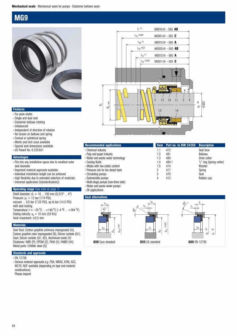
54
G50 Euro standard G55 US standard G60 EN 12756
Seat alternatives
l17
l29
d 14
d 16
±0,
05
R1
G50 (MG1S20) © EagleBurgmann
d 7
H8
d 6
H11
l6l5
20°
G60–MG1 © EagleBurgmann
l28
MG9
Mechanical seals · Mechanical seals for pumps · Elastomer bellows seals
l41
d 61 d 71
±0,
002“
l61
l51
30°
G55 © EagleBurgmann
Features• For plain shafts• Single and dual seal• Elastomer bellows rotating• Unbalanced• Independent of direction of rotation• No torsion on bellows and spring • Conical or cylindrical spring• Metric and inch sizes available • Special seat dimensions available• US Patent No. 6.220.601
Advantages• Fits into any installation space due to smallest outer seal diameter
• Important material approvals available• Individual installation length can be achieved• High flexibility due to extended selection of materials• Universal application (standardization))
Operating range (see note on page 1)Shaft diameter: d1 = 10 … 100 mm (0.375" … 4")Pressure: p1 = 12 bar (174 PSI),vacuum … 0,5 bar (7.25 PSI), up to bar (14.5 PSI) with seat lockingTemperature: t = – 20 °C … +140 °C (– 4 °F … +284 °F)Sliding velocity: vg = 10 m/s (33 ft/s)Axial movement: ±0.5 mm
MaterialsSeal face: Carbon graphite antimony impregnated (A), Carbon graphite resin impregnated (B), Silicon carbide (Q1) Seat: Silicon carbide (Q1, Q2), Aluminium oxide (V)Elastomer: NBR (P), EPDM (E), FKM (V), HNBR (X4)Metal parts: CrNiMo steel (G)
Standards and approvals• EN 12756• Various material approvals e.g. FDA, WRAS, KTW, ACS, W270, NSF available (depending on type and material combinations). Please inquire!
Recommended applications• Chemical industry• Pulp and paper industry• Water and waste water technology• Cooling fluids • Media with low solids content• Pressure oils for bio diesel fuels• Circulating pumps• Submersible pumps• Multi-stage pumps (non-drive side)• Water and waste water pumps• Oil applications
Item Part no. to DIN 24250 Description1.1 472 Seal face1.2 481 Bellows1.3 485 Drive collar1.4 484.1 “L” ring (spring collar)1.5 474 Washer2 477 Spring3 475 Seat4 412 Rubber cup
2 1.2 1.5 1.1 3 4
1.3 1.4
d 1
h8
–0,0
02´́
d b
min
d a
l1 ±1
l15 ±0,04´́
l1N ±1
l1S ±0,8
l1k ±1
l14 ±0,03´́
MG910/d1 – G50 AB
MG901/d1 – G55 C
MG913/d1 – G60 A
MG920/d1 – G50 AB
MG921/d1 – G55 C
MG912/d1 – G60 A
MG9 © EagleBurgmann

55
Table A – Dimensions in mmd1 d6 d7 d14 d16 da db l1 l1k l1N l1S l5 l6 l17 l28 l2910 17 21 11.0 24.60 19.6 13.0 53.0 32.5 40 34.0 1.5 4 7.5 6.6 9.012 19 23 13.5 27.80 21.6 15.0 53.0 32.5 40 34.0 1.5 4 7.5 6.6 9.014 21 25 17.0 30.95 24.0 18.0 54.5 35.0 40 35.5 1.5 4 9.0 6.6 10.515 – – 17.0 30.95 25.0 19.0 54.5 – – 35.5 – – 9.0 – 10.516 23 27 17.0 30.95 26.5 20.0 54.5 35.0 40 35.5 1.5 4 9.0 6.6 10.518 27 33 20.0 34.15 29.0 22.0 54.5 37.5 45 35.5 2.0 5 9.0 7.5 10.520 29 35 21.5 35.70 31.5 24.5 54.5 37.5 45 35.5 2.0 5 9.0 7.5 10.522 31 37 23.0 37.30 33.0 27.0 54.5 37.5 45 35.5 2.0 5 9.0 7.5 10.524 33 39 26.5 40.50 37.0 29.0 54.5 40.0 50 35.5 2.0 5 9.0 7.5 10.525 34 40 26.5 40.50 38.0 30.0 54.5 40.0 50 35.5 2.0 5 9.0 7.5 10.528 37 43 29.5 47.65 41.0 34.0 72.0 42.5 50 45.0 2.0 5 10.5 7.5 12.030 39 45 32.5 50.80 43.0 36.0 72.0 42.5 50 45.0 2.0 5 10.5 7.5 12.032 42 48 32.5 50.80 45.0 38.0 72.0 42.5 55 45.0 2.0 5 10.5 7.5 12.033 42 48 36.5 54.00 46.0 39.0 72.0 42.5 55 45.0 2.0 5 10.5 7.5 12.035 44 50 36.5 54.00 48.0 41.0 72.0 42.5 55 45.0 2.0 5 10.5 7.5 12.038 49 56 39.5 57.15 52.5 44.5 72.0 45.0 55 45.0 2.0 6 10.5 9.0 12.040 51 58 42.5 60.35 55.5 47.5 72.0 45.0 55 45.0 2.0 6 10.5 9.0 12.043 54 61 46.0 63.50 58.5 50.5 83.0 45.0 60 53.0 2.0 6 10.5 9.0 12.045 56 63 46.0 63.50 60.5 52.5 83.0 45.0 60 53.0 2.0 6 10.5 9.0 12.048 59 66 49.0 66.70 64.0 56.0 83.0 45.0 60 53.0 2.0 6 10.5 9.0 12.050 62 70 52.0 69.85 66.0 58.0 84.5 47.5 60 54.5 2.5 6 12.0 9.5 13.553 65 73 55.5 73.05 69.0 61.0 84.5 47.5 70 54.5 2.5 6 12.0 11.0 13.555 67 75 58.5 76.20 71.0 63.0 84.5 47.5 70 54.5 2.5 6 12.0 11.0 13.558 70 78 61.5 79.40 76.0 66.0 84.5 52.5 70 54.5 2.5 6 12.0 11.0 13.5
60 72 80 61.5 79.40 78.0 68.0 84.5 52.5 70 54.5 2.5 6 12.0 11.0 13.563 75 83 65.0 82.55 82.0 71.5 84.5 52.5 70 54.5 2.5 6 12.0 11.0 13.565 77 85 68.0 92.10 84.0 73.5 86.0 52.5 80 65.0 2.5 6 14.5 11.0 16.068 81 90 71.0 95.25 87.0 76.5 86.0 52.5 80 65.0 2.5 7 14.5 11.3 16.070 83 92 71.0 95.25 89.0 79.0 86.0 60.0 80 65.0 2.5 7 14.5 11.3 16.075 88 97 77.5 101.60 95.0 85.0 89.0 60.0 80 68.0 2.5 7 14.5 11.3 16.080 95 105 84.0 114.30 101.5 91.5 99.0 60.0 90 76.0 3.0 7 18.5 12.0 20.085 100 110 87.0 117.50 107.0 97.0 99.0 60.0 90 76.0 3.0 7 18.5 14.0 20.090 105 115 93.5 123.85 111.5 103.0 103.0 65.0 90 79.0 3.0 7 18.5 14.0 20.095 110 120 96.5 127.00 117.5 108.0 103.0 65.0 90 79.0 3.0 7 18.5 14.0 20.0
100 115 125 103.0 133.35 122.5 114.0 106.0 65.0 90 82.0 3.0 7 18.5 14.0 20.0
MG9 … the alternativeEagleBurgmann* Crane* Sealol* Abmessungen TableMG910/d1-G50 1A 43 CE long Inch/mm B
1A 43 CE long mm A MG920/d1-G50 2 43 CE short Inch/mm B
2 43 CE short mm A MG901/d1-G55 1 43 CU long Inch (USA only) C MG921/d1-G55 2 43 CU short Inch (USA only) C
21 43 CU short Inch (USA only) C MG912/d1-G60 502 43 DIN mm A
521 43 DIN mm A 2100-l1k 43 DIN mm A
MG913/d1-G60 2100-l1N mm A
* Connection dimensions identical
Table B – Dimensions in inch / mmd1 d1 d14 d16 da db l1 l1S l17 l290.375" 9.53 11.0 24.60 18.8 12.5 53.0 34.0 7.5 9.00.500" 12.70 13.5 27.80 22.3 16.0 53.0 34.0 7.5 9.00.625" 15.88 17.0 30.95 26.5 20.0 54.5 35.5 9.0 10.50.750" 19.05 20.0 34.15 29.5 23.0 54.5 35.5 9.0 10.50.875" 22.23 23.0 37.30 33.0 27.0 54.5 35.5 9.0 10.51.000" 25.40 26.5 40.50 38.0 30.5 54.5 35.5 9.0 10.51.125" 28.58 29.5 47.65 41.5 34.5 72.0 45.0 10.5 12.01.250" 31.75 32.5 50.80 45.0 38.0 72.0 45.0 10.5 12.01.375" 34.93 36.5 54.00 48.0 41.0 72.0 45.0 10.5 12.01.500" 38.10 39.5 57.15 52.5 44.5 72.0 45.0 10.5 12.01.625" 41.28 42.5 60.35 57.0 48.5 72.0 45.0 10.5 12.01.750" 44.45 46.0 63.50 60.5 51.5 83.0 53.0 10.5 12.01.875" 47.63 49.0 66.70 64.0 55.0 83.0 53.0 10.5 12.02.000" 50.80 52.0 69.85 66.0 58.0 84.5 54.5 12.0 13.52.125" 53.98 55.5 73.05 71.0 61.5 84.5 54.5 12.0 13.52.250" 57.15 58.5 76.20 76.5 65.0 84.5 54.5 12.0 13.52.375" 60.33 61.5 79.40 78.5 68.5 84.5 54.5 12.0 13.52.500" 63.50 65.0 82.55 82.0 72.0 84.5 54.5 12.0 13.52.625" 66.68 68.0 92.10 84.0 75.0 86.0 65.0 14.5 16.02.750" 69.85 71.0 95.25 89.0 79.0 86.0 65.0 14.5 16.02.875" 73.03 74.5 98.45 92.5 82.0 89.0 68.0 14.5 16.03.000" 76.20 77.5 101.60 95.5 85.5 89.0 68.0 14.5 16.03.125" 79.38 80.5 111.15 101.5 91.0 99.0 76.0 18.5 20.03.250" 82.55 84.0 114.30 104.7 94.0 99.0 76.0 18.5 20.03.375" 85.73 87.0 117.50 107.0 98.0 99.0 76.0 18.5 20.03.500" 88.90 90.5 120.65 111.5 100.0 99.0 76.0 18.5 20.03.625" 92.08 93.5 123.85 114.5 104.0 103.0 79.0 18.5 20.03.750" 95.25 96.5 127.00 118.0 108.0 103.0 79.0 18.5 20.03.875" 98.43 100.0 130.20 121.0 112.0 106.0 82.0 18.5 20.04.000" 101.60 103.0 133.35 125.0 116.0 106.0 82.0 18.5 20.0
Table C – Dimensions in inchd1 d61 d71 da db l14 l15 l41 l51 l610.375 0.625 0.875 0.740 0.492 1.125 1.500 0.313 0.050 0.2500.500 0.750 1.000 0.878 0.630 1.125 1.500 0.313 0.050 0.2500.625 0.937 1.250 1.043 0.787 1.281 1.718 0.406 0.050 0.3440.750 1.062 1.375 1.161 0.905 1.281 1.718 0.406 0.050 0.3440.875 1.187 1.500 1.299 1.063 1.343 1.781 0.406 0.050 0.3441.000 1.312 1.625 1.496 1.200 1.437 2.000 0.437 0.050 0.3751.125 1.437 1.750 1.634 1.358 1.500 2.062 0.437 0.050 0.3751.250 1.563 1.875 1.772 1.496 1.500 2.062 0.437 0.050 0.3751.375 1.687 2.000 1.890 1.614 1.562 2.124 0.437 0.050 0.3751.500 1.813 2.125 2.067 1.752 1.562 2.124 0.437 0.050 0.3751.625 2.000 2.375 2.244 1.909 1.875 2.500 0.500 0.050 0.4371.750 2.125 2.500 2.382 2.028 1.875 2.500 0.500 0.050 0.4371.875 2.250 2.625 2.520 2.165 2.000 2.625 0.500 0.050 0.4372.000 2.375 2.750 2.598 2.283 2.000 2.625 0.500 0.050 0.4372.125 2.375 3.000 2.795 2.421 2.249 2.937 0.562 0.050 0.5002.250 2.437 3.125 2.992 2.559 2.249 2.937 0.562 0.050 0.5002.375 2.563 3.250 3.071 2.697 2.375 3.062 0.562 0.050 0.5002.500 2.687 3.375 3.228 2.834 2.375 3.062 0.562 0.050 0.5002.625 2.812 3.375 3.307 2.953 2.562 3.375 0.625 0.100 0.5622.750 2.937 3.500 3.504 3.110 2.562 3.375 0.625 0.100 0.5622.875 3.062 3.750 3.642 3.228 2.687 3.500 0.625 0.100 0.5623.000 3.187 3.875 3.760 3.366 2.687 3.500 0.625 0.100 0.5623.125 3.312 4.000 4.000 3.583 2.968 3.906 0.781 0.100 0.6563.250 3.437 4.125 4.122 3.700 2.968 3.906 0.781 0.100 0.6563.375 3.562 4.250 4.213 3.858 2.968 3.906 0.781 0.100 0.6563.500 3.687 4.375 4.390 3.937 2.968 3.906 0.781 0.100 0.6563.625 3.812 4.500 4.508 4.095 3.093 4.031 0.781 0.100 0.6563.750 3.937 4.625 4.646 4.252 3.093 4.031 0.781 0.100 0.6563.875 4.062 4.750 4.764 4.409 3.218 4.156 0.781 0.100 0.6564.000 4.187 4.875 4.921 4.567 3.218 4.156 0.781 0.100 0.656
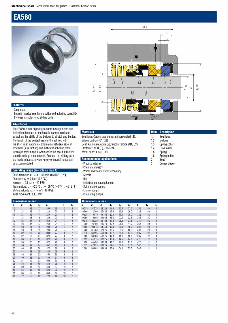
56
EA560
Mechanical seals · Mechanical seals for pumps · Elastomer bellows seals
Dimensions in mmd d1 d2 d3 d4 l l1 l28 21 13 12 20,0 18 7 29 24 16 13 21,0 23 7 2
10 24 16 14 23,5 23 7 211 24 16 15 23,5 23 7 212 26 17 16 26,0 24 7 213 26 17 17 26,0 24 7 214 28 21 18 28,0 25 7 215 28 21 19 28,0 25 7 216 32 22 20 30,0 27 8 217 32 22 21 32,5 27 8 218 35 25 22 32,5 26 8 219 35 25 23 32,5 26 8 220 38 27 24 35,5 28 8 222 40 29 26 37,5 28 8 225 44 32 29 42,0 29 9 228 46 34 32 45,5 30 9 230 50 38 35 48,0 31 9 232 54 40 37 50,0 33 9 235 58 44 40 54,5 36 10 238 60 46 43 58,5 37 10 240 64 48 45 62,5 38 10 245 66 52 50 66,5 40 10 250 72 58 55 72,5 42 10 2
Dimensions in inchd d d1 d2 d3 d4 l l1 l20.375 9.525 22.225 14.3 12.7 23.5 28.6 6.4 10.500 12.700 25.400 17.5 15.9 26.0 28.6 6.4 10.625 15.875 31.750 20.6 19.1 30.0 32.5 8.7 10.750 19.050 34.925 23.8 22.2 32.5 32.5 8.7 10.875 22.225 38.100 27.0 25.4 37.5 34.1 8.7 11.000 25.400 41.275 30.2 28.6 44.0 36.5 9.5 11.125 28.575 44.450 33.3 31.8 48.0 38.1 9.5 11.250 31.750 47.625 36.5 34.9 50.0 38.1 9.5 11.375 34.925 50.800 39.7 38.1 54.5 39.7 9.5 11.500 38.100 53.975 42.9 41.3 58.5 39.7 9.5 11.625 41.275 60.325 46.0 44.5 64.0 47.6 11.1 11.750 44.450 63.500 49.2 47.6 67.0 47.6 11.1 11.875 47.625 66.675 52.4 50.8 71.0 50.8 11.1 12.000 50.800 69.850 55.6 54.0 73.5 50.8 11.1 1
Features• Single seal• Loosely inserted seal face provides self-adjusting capability• In-house manufactured sliding parts
AdvantagesThe EA560 is self-adjusting to shaft misalignments and deflections because of the loosely inserted seal face as well as the ability of the bellows to stretch and tighten. The length of the contact area of the bellows with the shaft is an optimum compromise between ease of assembly (less friction) and sufficient adhesive force for torque transmission. Additionally the seal fulfills very specific leakage requirements. Because the sliding parts are made in-house, a wide variety of special needs can be accommodated.
Operating range (see note on page 1)Shaft diameter: d1 = 8 … 50 mm (0.375" … 2")Pressure: p1 = 7 bar (102 PSI), vacuum … 0.1 bar (1.45 PSI)Temperature: t = – 20 °C … +100 °C (– 4 °F … +212 °F)Sliding velocity: vg = 5 m/s (16 ft/s)Axial movement: ±1.0 mm
MaterialsSeal face: Carbon graphite resin impregnated (B),Silicon carbide (Q1, Q2) Seat: Aluminium oxide (V), Silicon carbide (Q1, Q2)Elastomer: NBR (P), FKM (V)Metal parts: 1.4301 (F)
Recommended applications• Process industry• Chemical industry• Water and waste water technology• Glycols• Oils• Industrial pumps/equipment• Submersible pumps• Engine pumps• Circulating pumps
Item Description1.1 Seal face1.2 Bellows1.3 Spring collar1.4 Drive collar1.5 Spring1.6 Spring holder2 Seat3 Corner sleeve
1.6 1.5 1.3 1.1 2 3
1.4 1.2d 4
max
d 3
min
l ±0,3
l1
l2
d h
9
d 1
H7
d 2
EA560 © EagleBurgmann
30°
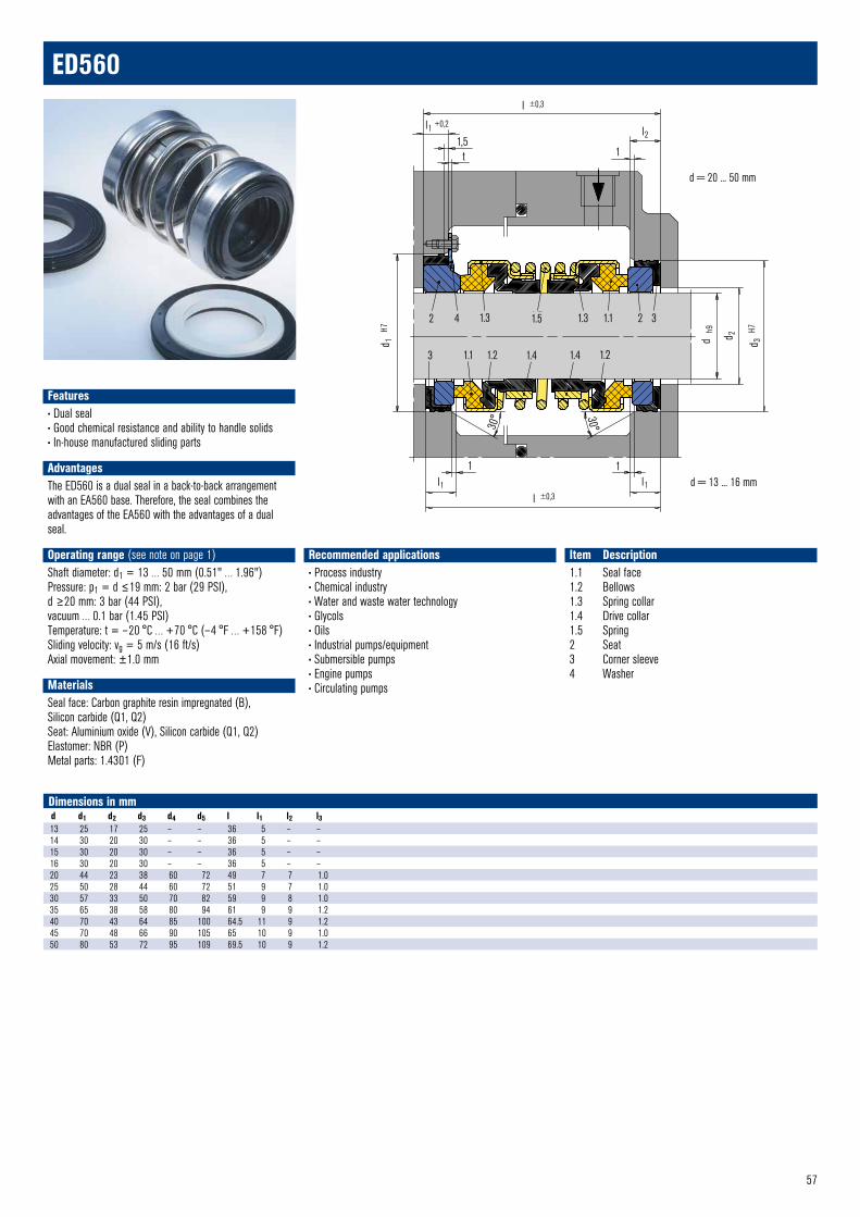
57
2 4 1.3 1.5 1.3 1.1 2 3
3 1.1 1.2 1.4 1.4 1.2
l ±0,3
l1 +0,2
1,5t 1
l2
d = 20 ... 50 mm
d 3 H
7
d h9 d 2
d 1
H7
l ±0,3
l1
1 1l1 d = 13 ... 16 mm
ED560 © EagleBurgmann
30°30°
ED560
Dimensions in mm d d1 d2 d3 d4 d5 l l1 l2 l313 25 17 25 – – 36 5 – –14 30 20 30 – – 36 5 – –15 30 20 30 – – 36 5 – –16 30 20 30 – – 36 5 – –20 44 23 38 60 72 49 7 7 1.025 50 28 44 60 72 51 9 7 1.030 57 33 50 70 82 59 9 8 1.035 65 38 58 80 94 61 9 9 1.240 70 43 64 85 100 64.5 11 9 1.245 70 48 66 90 105 65 10 9 1.050 80 53 72 95 109 69.5 10 9 1.2
Features• Dual seal• Good chemical resistance and ability to handle solids• In-house manufactured sliding parts
AdvantagesThe ED560 is a dual seal in a back-to-back arrange ment with an EA560 base. Therefore, the seal combines the advantages of the EA560 with the advantages of a dual seal.
Operating range (see note on page 1)Shaft diameter: d1 = 13 … 50 mm (0.51" … 1.96")Pressure: p1 = d ≤19 mm: 2 bar (29 PSI),d ≥20 mm: 3 bar (44 PSI),vacuum … 0.1 bar (1.45 PSI)Temperature: t = – 20 °C … +70 °C (– 4 °F … +158 °F)Sliding velocity: vg = 5 m/s (16 ft/s)Axial movement: ±1.0 mm
MaterialsSeal face: Carbon graphite resin impregnated (B),Silicon carbide (Q1, Q2) Seat: Aluminium oxide (V), Silicon carbide (Q1, Q2)Elastomer: NBR (P)Metal parts: 1.4301 (F)
Recommended applications• Process industry• Chemical industry• Water and waste water technology• Glycols• Oils• Industrial pumps/equipment• Submersible pumps• Engine pumps• Circulating pumps
Item Description1.1 Seal face1.2 Bellows1.3 Spring collar1.4 Drive collar1.5 Spring2 Seat3 Corner sleeve4 Washer
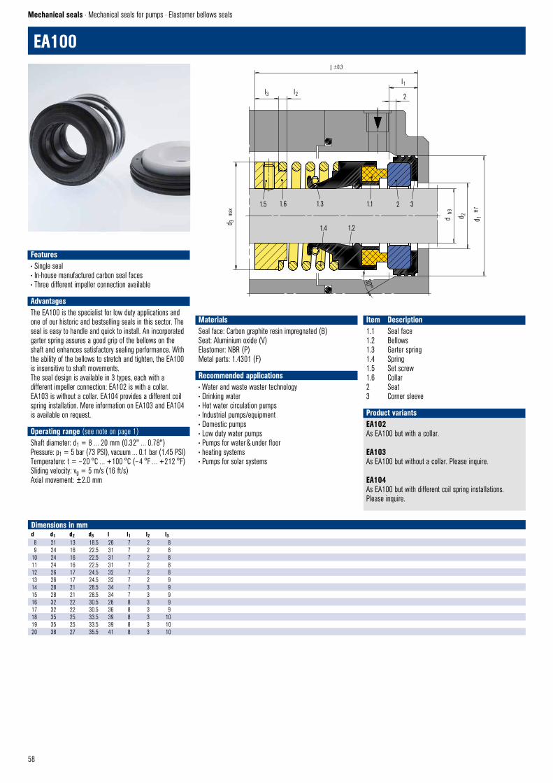
58
l3 l2
l ±0,3
l1
2
d h9 d 2 d 1 H
71.5 1.6 1.3 1.1 2 3
1.4 1.2
EA102 © EagleBurgmann
30°
d 3
max
EA100
Mechanical seals · Mechanical seals for pumps · Elastomer bellows seals
Dimensions in mmd d1 d2 d3 l l1 l2 l38 21 13 18.5 26 7 2 89 24 16 22.5 31 7 2 8
10 24 16 22.5 31 7 2 811 24 16 22.5 31 7 2 812 26 17 24.5 32 7 2 813 26 17 24.5 32 7 2 914 28 21 28.5 34 7 3 915 28 21 28.5 34 7 3 916 32 22 30.5 26 8 3 917 32 22 30.5 36 8 3 918 35 25 33.5 39 8 3 1019 35 25 33.5 39 8 3 1020 38 27 35.5 41 8 3 10
EA102As EA100 but with a collar.
EA103As EA100 but without a collar. Please inquire.
EA104As EA100 but with different coil spring installations.Please inquire.
Product variants
Features• Single seal• In-house manufactured carbon seal faces• Three different impeller connection available
AdvantagesThe EA100 is the specialist for low duty applications and one of our historic and bestselling seals in this sector. The seal is easy to handle and quick to install. An incorporated garter spring assures a good grip of the bellows on the shaft and enhances satisfactory sealing performance. With the ability of the bellows to stretch and tighten, the EA100 is insensitive to shaft movements. The seal design is available in 3 types, each with a different impeller connection: EA102 is with a collar. EA103 is without a collar. EA104 provides a different coil spring installation. More information on EA103 and EA104 is available on request.
Operating range (see note on page 1)Shaft diameter: d1 = 8 … 20 mm (0.32" … 0.78")Pressure: p1 = 5 bar (73 PSI), vacuum … 0.1 bar (1.45 PSI)Temperature: t = – 20 °C … +100 °C (– 4 °F … +212 °F)Sliding velocity: vg = 5 m/s (16 ft/s)Axial movement: ±2.0 mm
MaterialsSeal face: Carbon graphite resin impregnated (B) Seat: Aluminium oxide (V)Elastomer: NBR (P) Metal parts: 1.4301 (F)
Recommended applications• Water and waste waster technology• Drinking water• Hot water circulation pumps• Industrial pumps/equipment• Domestic pumps• Low duty water pumps• Pumps for water & under floor• heating systems• Pumps for solar systems
Item Description1.1 Seal face1.2 Bellows1.3 Garter spring 1.4 Spring1.5 Set screw1.6 Collar2 Seat3 Corner sleeve
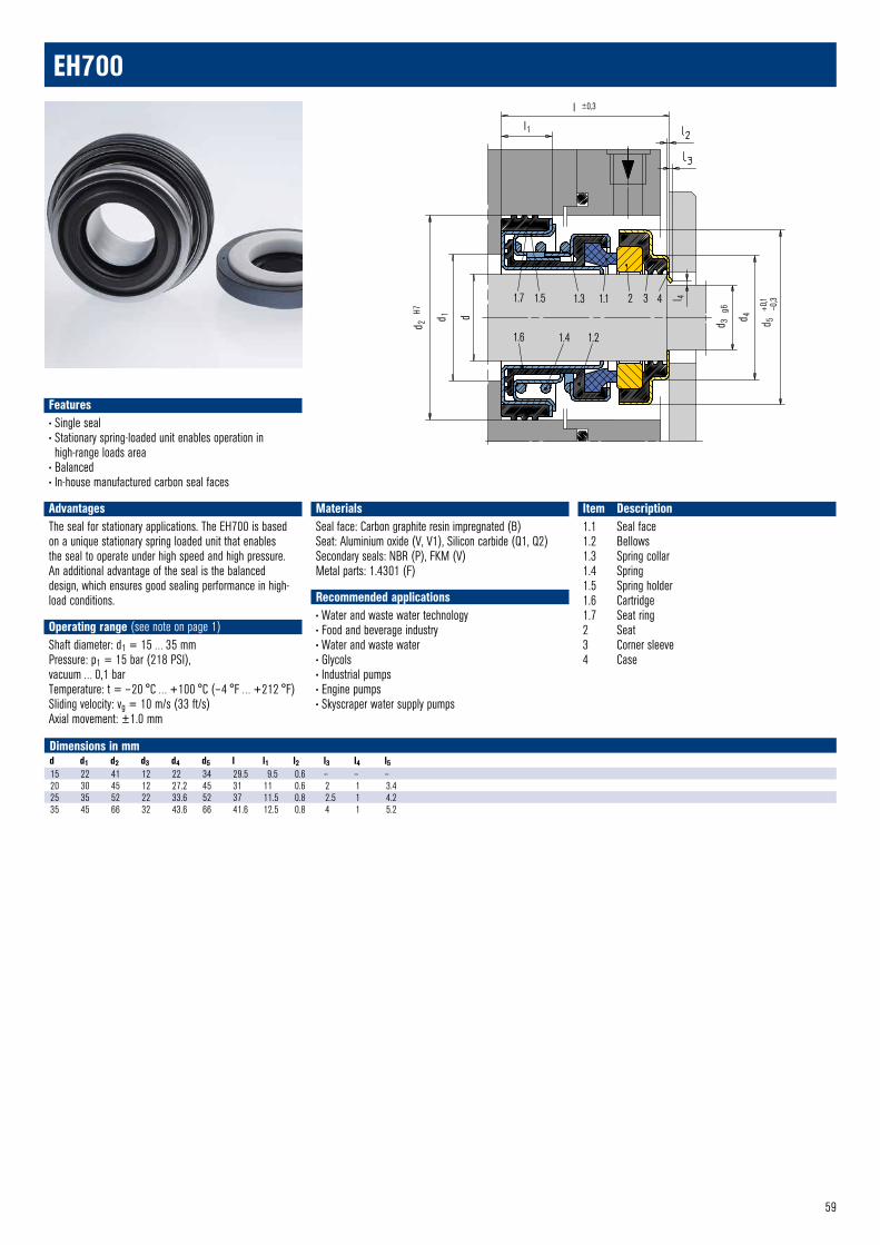
59
Features• Single seal• Stationary spring-loaded unit enables operation in high-range loads area
• Balanced• In-house manufactured carbon seal faces
AdvantagesThe seal for stationary applications. The EH700 is based on a unique stationary spring loaded unit that enablesthe seal to operate under high speed and high pressure. An additional advantage of the seal is the balanced design, which ensures good sealing performance in high-load conditions.
Operating range (see note on page 1)Shaft diameter: d1 = 15 … 35 mmPressure: p1 = 15 bar (218 PSI),vacuum … 0,1 barTemperature: t = – 20 °C … +100 °C (– 4 °F … +212 °F)Sliding velocity: vg = 10 m/s (33 ft/s)Axial movement: ±1.0 mm
MaterialsSeal face: Carbon graphite resin impregnated (B)Seat: Aluminium oxide (V, V1), Silicon carbide (Q1, Q2)Secondary seals: NBR (P), FKM (V)Metal parts: 1.4301 (F)
Recommended applications• Water and waste water technology• Food and beverage industry• Water and waste water• Glycols• Industrial pumps• Engine pumps• Skyscraper water supply pumps
Item Description1.1 Seal face1.2 Bellows1.3 Spring collar1.4 Spring1.5 Spring holder1.6 Cartridge1.7 Seat ring2 Seat3 Corner sleeve4 Case
1.7 1.5 1.3 1.1 2 3 4
1.6 1.4 1.2
d 2
H7
d 1 d
d 3
g6
d 4
d 5
+0,1
–0,
3l 4
l ±0,3
l1
EH700 © EagleBurgmann
EH700
Dimensions in mmd d1 d2 d3 d4 d5 l l1 l2 l3 l4 l515 22 41 12 22 34 29.5 9.5 0.6 – – –20 30 45 12 27.2 45 31 11 0.6 2 1 3.425 35 52 22 33.6 52 37 11.5 0.8 2.5 1 4.235 45 66 32 43.6 66 41.6 12.5 0.8 4 1 5.2
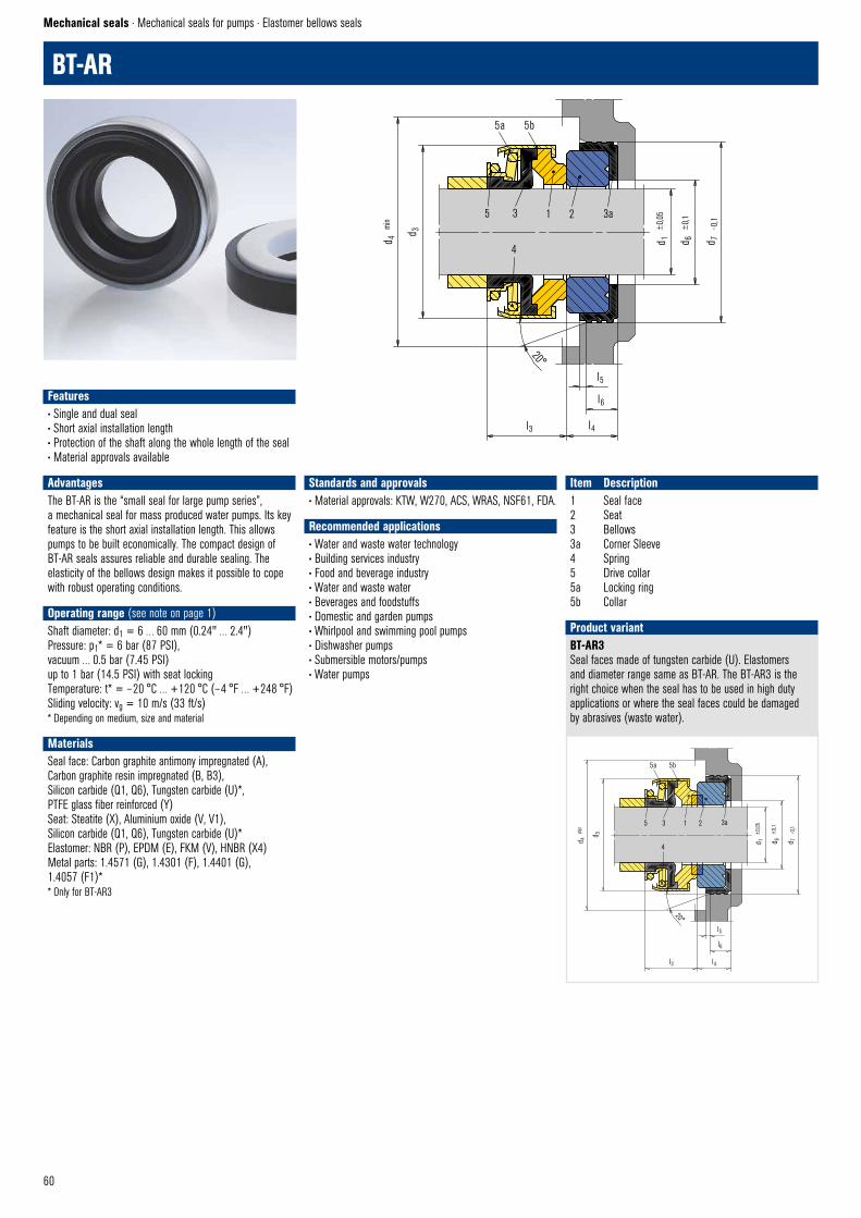
60
BT-AR
Mechanical seals · Mechanical seals for pumps · Elastomer bellows seals
BT-AR3Seal faces made of tungsten carbide (U). Elastomers and diameter range same as BT-AR. The BT-AR3 is the right choice when the seal has to be used in high duty applications or where the seal faces could be damaged by abrasives (waste water).
Product variant
Features• Single and dual seal• Short axial installation length• Protection of the shaft along the whole length of the seal• Material approvals available
AdvantagesThe BT-AR is the “small seal for large pump series”, a mechanical seal for mass produced water pumps. Its key feature is the short axial installation length. This allows pumps to be built economically. The compact design of BT-AR seals assures reliable and durable sealing. The elasticity of the bellows design makes it possible to cope with robust operating conditions.
Operating range (see note on page 1)Shaft diameter: d1 = 6 … 60 mm (0.24" … 2.4")Pressure: p1* = 6 bar (87 PSI),vacuum … 0.5 bar (7.45 PSI)up to 1 bar (14.5 PSI) with seat lockingTemperature: t* = – 20 °C … +120 °C (– 4 °F … +248 °F)Sliding velocity: vg = 10 m/s (33 ft/s)* Depending on medium, size and material
MaterialsSeal face: Carbon graphite antimony impregnated (A), Carbon graphite resin impregnated (B, B3),Silicon carbide (Q1, Q6), Tungsten carbide (U)*,PTFE glass fiber reinforced (Y) Seat: Steatite (X), Aluminium oxide (V, V1), Silicon carbide (Q1, Q6), Tungsten carbide (U)* Elastomer: NBR (P), EPDM (E), FKM (V), HNBR (X4) Metal parts: 1.4571 (G), 1.4301 (F), 1.4401 (G),1.4057 (F1)** Only for BT-AR3
Standards and approvals• Material approvals: KTW, W270, ACS, WRAS, NSF61, FDA.
Recommended applications• Water and waste water technology• Building services industry• Food and beverage industry• Water and waste water• Beverages and foodstuffs• Domestic and garden pumps• Whirlpool and swimming pool pumps• Dishwasher pumps• Submersible motors/pumps• Water pumps
Item Description1 Seal face2 Seat3 Bellows3a Corner Sleeve4 Spring5 Drive collar5a Locking ring5b Collar
5a 5b
5 3 1 2 3a
4
d 4
min
d 3
d 1
±0,
05
d 6
±0,
1
d 7
– 0,1
20°
l3 l4
l5
l6
BT–AR © EagleBurgmann
5a 5b
5 3 1 2 3a
4
d 4
min
d 3
d 1
±0,
05
d 6
±0,
1
d 7
–0,1
20°
l3
l5
l6
l4
BT–AR3 © EagleBurgmann
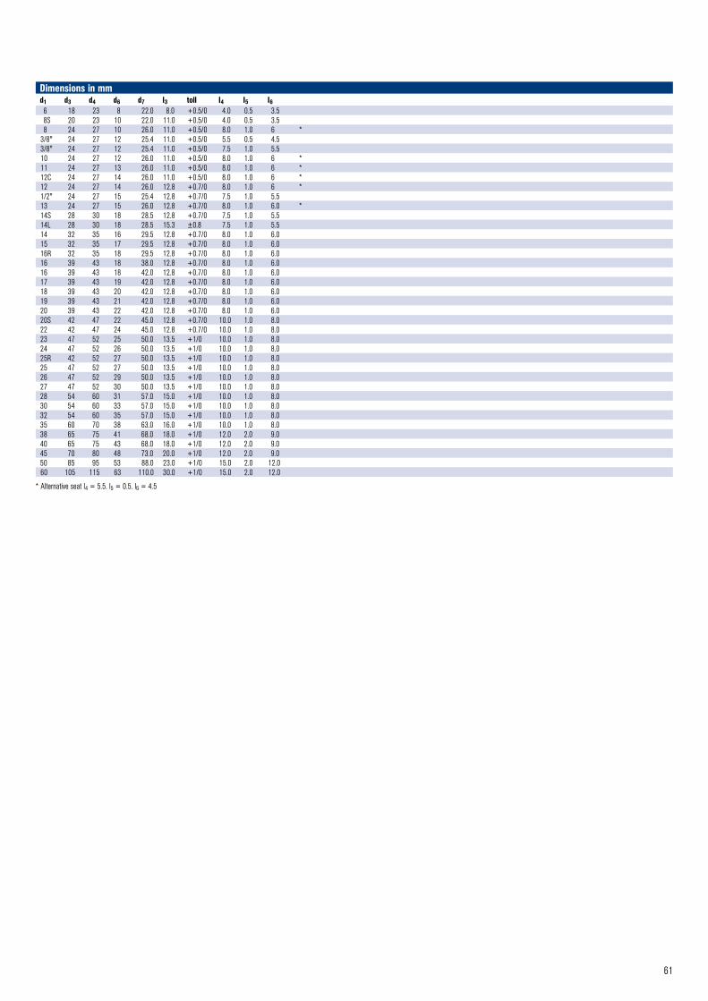
61
Dimensions in mmd1 d3 d4 d6 d7 I3 toll I4 I5 I66 18 23 8 22.0 8.0 +0.5/0 4.0 0.5 3.58S 20 23 10 22.0 11.0 +0.5/0 4.0 0.5 3.58 24 27 10 26.0 11.0 +0.5/0 8.0 1.0 6 *
3/8" 24 27 12 25.4 11.0 +0.5/0 5.5 0.5 4.53/8" 24 27 12 25.4 11.0 +0.5/0 7.5 1.0 5.510 24 27 12 26.0 11.0 +0.5/0 8.0 1.0 6 *11 24 27 13 26.0 11.0 +0.5/0 8.0 1.0 6 *12C 24 27 14 26.0 11.0 +0.5/0 8.0 1.0 6 *12 24 27 14 26.0 12.8 +0.7/0 8.0 1.0 6 *1/2" 24 27 15 25.4 12.8 +0.7/0 7.5 1.0 5.513 24 27 15 26.0 12.8 +0.7/0 8.0 1.0 6.0 *14S 28 30 18 28.5 12.8 +0.7/0 7.5 1.0 5.514L 28 30 18 28.5 15.3 ±0.8 7.5 1.0 5.514 32 35 16 29.5 12.8 +0.7/0 8.0 1.0 6.015 32 35 17 29.5 12.8 +0.7/0 8.0 1.0 6.016R 32 35 18 29.5 12.8 +0.7/0 8.0 1.0 6.016 39 43 18 38.0 12.8 +0.7/0 8.0 1.0 6.016 39 43 18 42.0 12.8 +0.7/0 8.0 1.0 6.017 39 43 19 42.0 12.8 +0.7/0 8.0 1.0 6.018 39 43 20 42.0 12.8 +0.7/0 8.0 1.0 6.019 39 43 21 42.0 12.8 +0.7/0 8.0 1.0 6.020 39 43 22 42.0 12.8 +0.7/0 8.0 1.0 6.020S 42 47 22 45.0 12.8 +0.7/0 10.0 1.0 8.022 42 47 24 45.0 12.8 +0.7/0 10.0 1.0 8.023 47 52 25 50.0 13.5 +1/0 10.0 1.0 8.024 47 52 26 50.0 13.5 +1/0 10.0 1.0 8.025R 42 52 27 50.0 13.5 +1/0 10.0 1.0 8.025 47 52 27 50.0 13.5 +1/0 10.0 1.0 8.026 47 52 29 50.0 13.5 +1/0 10.0 1.0 8.027 47 52 30 50.0 13.5 +1/0 10.0 1.0 8.028 54 60 31 57.0 15.0 +1/0 10.0 1.0 8.030 54 60 33 57.0 15.0 +1/0 10.0 1.0 8.032 54 60 35 57.0 15.0 +1/0 10.0 1.0 8.035 60 70 38 63.0 16.0 +1/0 10.0 1.0 8.038 65 75 41 68.0 18.0 +1/0 12.0 2.0 9.040 65 75 43 68.0 18.0 +1/0 12.0 2.0 9.045 70 80 48 73.0 20.0 +1/0 12.0 2.0 9.050 85 95 53 88.0 23.0 +1/0 15.0 2.0 12.060 105 115 63 110.0 30.0 +1/0 15.0 2.0 12.0
* Alternative seat l4 = 5.5. l5 = 0.5. l6 = 4.5
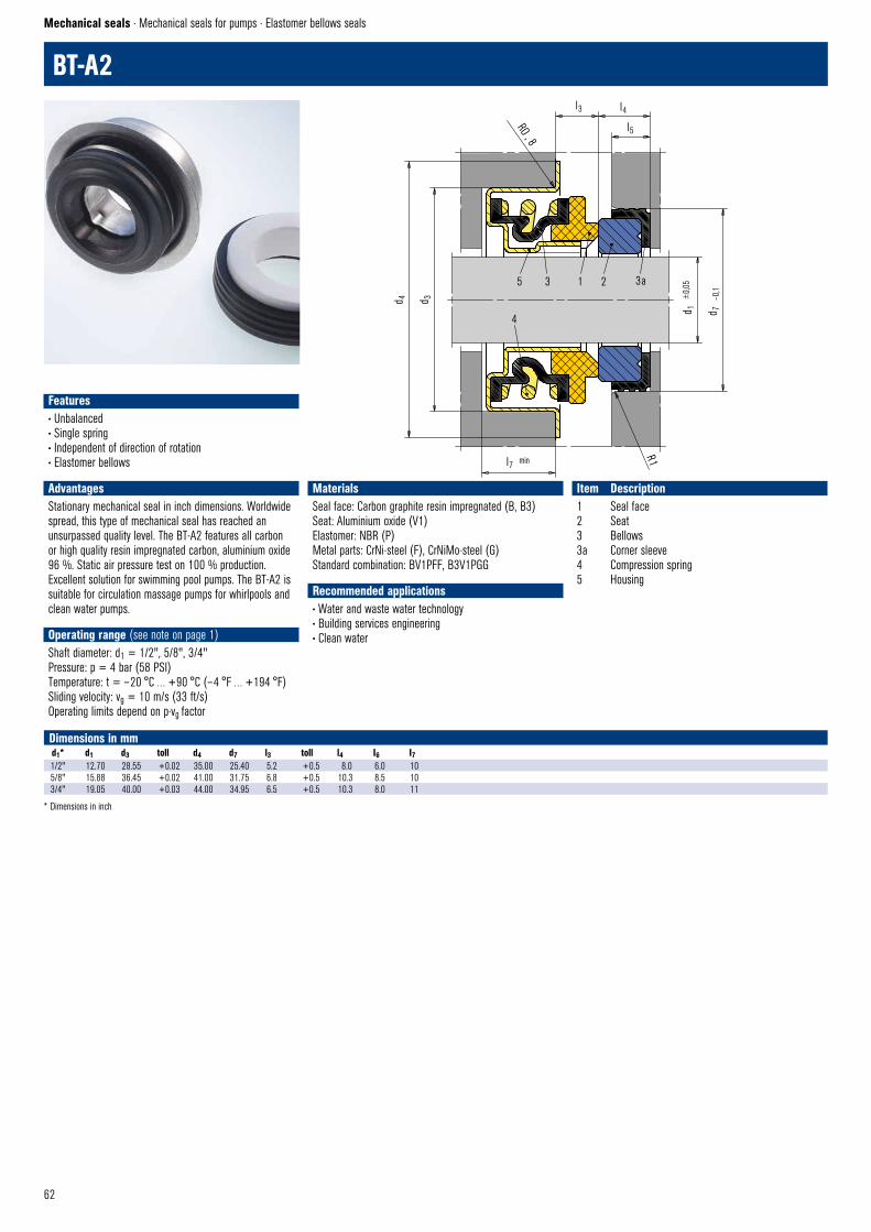
62
BT-A2
Mechanical seals · Mechanical seals for pumps · Elastomer bellows seals
Dimensions in mm d1* d1 d3 toll d4 d7 l3 toll l4 I6 I71/2" 12.70 28.55 +0.02 35.00 25.40 5.2 +0.5 8.0 6.0 105/8" 15.88 36.45 +0.02 41.00 31.75 6.8 +0.5 10.3 8.5 103/4" 19.05 40.00 +0.03 44.00 34.95 6.5 +0.5 10.3 8.0 11
* Dimensions in inch
Features• Unbalanced• Single spring• Independent of direction of rotation• Elastomer bellows
AdvantagesStationary mechanical seal in inch dimensions. Worldwide spread, this type of mechanical seal has reached an unsurpassed quality level. The BT-A2 features all carbon or high quality resin impregnated carbon, aluminium oxide 96 %. Static air pressure test on 100 % production. Excellent solution for swimming pool pumps. The BT-A2 is suitable for circulation massage pumps for whirlpools and clean water pumps.
Operating range (see note on page 1)Shaft diameter: d1 = 1/2", 5/8", 3/4"Pressure: p = 4 bar (58 PSI)Temperature: t = – 20 °C … +90 °C (– 4 °F … +194 °F)Sliding velocity: vg = 10 m/s (33 ft/s)Operating limits depend on p·vg factor
MaterialsSeal face: Carbon graphite resin impregnated (B, B3)Seat: Aluminium oxide (V1)Elastomer: NBR (P)Metal parts: CrNi-steel (F), CrNiMo-steel (G)Standard combination: BV1PFF, B3V1PGG
Recommended applications• Water and waste water technology• Building services engineering• Clean water
Item Description1 Seal face2 Seat3 Bellows3a Corner sleeve4 Compression spring5 Housing
5 3 1 2 3a
4
d 4 d 3
d 1
±0,
05
d 7
–0,1
l7 min
R1
l3 l4
l5
RO , 8
BT – A2 © EagleBurgmann

63
BT-PN
Dimensions in mm d1 d3 d6 d7 l1 l3 toll l4 l5 l68.00 23 10 22.00 17.50 13.50 ±1 4.0 0.5 3.58.00 23 10 25.40 19.00 13.50 ±1 5.5 0.5 4.5 3/8" 23 12 25.40 19.00 13.50 ±1 5.5 0.5 4.5
10.00 23 12 25.40 19.00 13.50 ±1 5.5 0.5 4.513.00 32 17 29.50 20.80 12.80 +0.7/0 8.0 1.0 6.014.00 32 17 29.50 20.80 12.80 +0.7/0 8.0 1.0 6.015.00 32 17 29.50 20.80 12.80 +0.7/0 8.0 1.0 6.016.00 32 17 29.50 20.80 12.80 +0.7/0 8.0 1.0 6.016.00 32 17 29.50 24.30 16.30 +0.7/0 8.0 1.0 6.0 4" submersible motor20.00 44 22 42.00 22.00 14.00 ±1 8.0 1.0 6.025.00 50 27 42.00 24.00 17.00 ±1 7.0 1.0 5.030.00 60 33 52.00 32.00 22.00 ±1 10.0 1.0 6.0
5 5a 5b 3 1 2 3a
4
20°
l3 l4
l6
l5
d 3
l1
d 1
±0,
05
d 6
±0,
1
d 7
– 0,1
BT–PN © EagleBurgmann
Features• Single and dual seal• Short axial installation length• Material approvals available
AdvantagesThe small seal for increased pressure. The BT-PN is a mechanical seal with a simple but effective design for mass-produced pumps. The special spring arrangement allows a short axial installation length. This advantage is combined with an increased working pressure capability and because the spring is free from torque transmission.
Operating range (see note on page 1)Shaft diameter: d1 = 8 … 30 mmPressure: p1* = 12 bar (170 PSI)Temperature: t* = – 20 °C … +120 °C (– 4 °C … +248 °F)Sliding velocity: vg = 10 m/s (33 ft/s)* Depending on medium, size and material
Materials Seal face: Carbon graphite resin impregnated (B), Carbon graphite solid (B3), Silicon carbide (Q1, Q6) Seat: Steatite (X), Aluminium oxide (V, V1), Silicon carbide (Q1, Q6) Elastomer: NBR (P), EPDM (E), FKM (V)Metal parts: 1.4571 (G), 1.4301 (F), 1.4401 (G)
Standards and approvals• Material approvals: KTW, W270, ACS, WRAS, NSF61, FDA.
NotesThe BT-PN can also be used as a dual seal in tandem or back-to-back arrangement. Installation proposals can be supplied on request.
Recommended applications• Water and waste water technology• Building services industry• Food and beverage industry• Water and waste water• Beverages and food stuffs• Submersible motors up to 4 inches• Submersible pumps, back-to-back installation• Peripheral pumps for industrial applications• Domestic and garden pumps• Coffee machines• Water pumps
Item Description1 Seal face2 Seat3 Bellows3a Corner sleeve4 Spring5 Spring holder5a Drive collar5b Collar

64
MBS100
Mechanical seals · Mechanical seals for pumps · Metal bellows seals
Features• For unstepped shafts• Rotating bellows• Single seal• Balanced• Independent of direction of rotation
Advantages• For extreme temperature ranges• No dynamically loaded O-Ring • Self cleaning effect
Operating range (see note on page 1)Shaft diameter: d1 = 20 … 100 mm (0.79" … 4")Pressure: p1 = … 25 (16*) bar (363 (232*) PSI)Temperature: t = – 40 °C … +220 °C (160*) °C (– 40 °F … +428 (320*) °F)Sliding velocity: vg = 20 m/s (66 ft/s)* Operating limits for material combination Q1/Q1
MaterialsSeal face: Carbon graphite (A), Silicon carbide (Q1)Seat: Silicon carbide (Q12)Bellows: Inconel® 625 (T3)Secondary seals: FKM (V)Metal parts: Duplex (G1)
Standards and approvals• EN 12756
Recommended applications• Process industry• Refining technology• Petrochemical industry• Chemical industry• Hot media• Cold media• Highly viscous media• Pumps• Special rotating equipment
Item Description1.1 Seal face with bellows unit1.2 O-Ring1.3 Set screw2 Seat (G9)3 O-Ring
1.3 1.2 1.1 2 3
l3 ±0,5
d 3
d 1 h
6
l8
l1K ±0,3
( l9)
9 ±0,5
d 6 H
11
d 7 H
8
20°
l5 l6
d8
5
MBS100 © EagleBurgmann
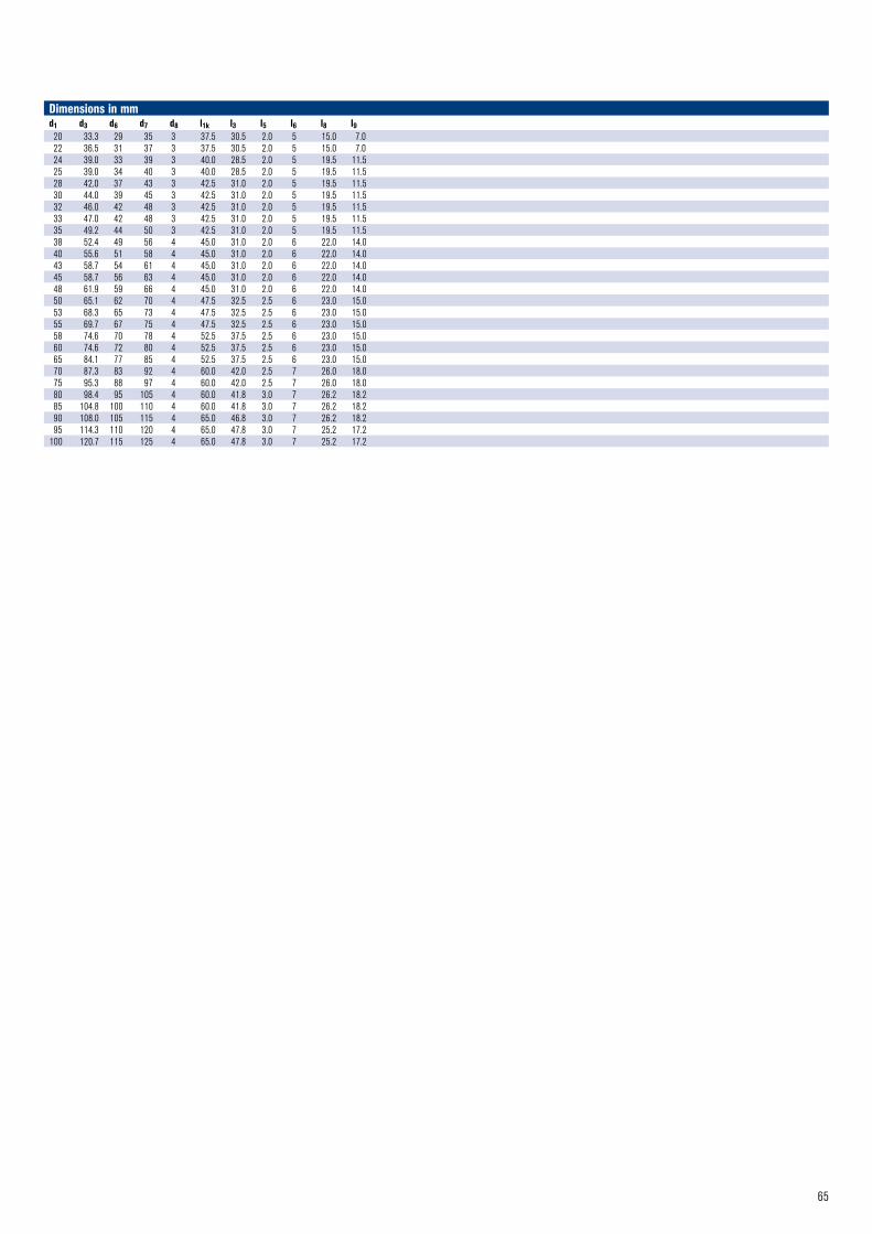
65
Dimensions in mmd1 d3 d6 d7 d8 l1k l3 l5 l6 l8 l920 33.3 29 35 3 37.5 30.5 2.0 5 15.0 7.022 36.5 31 37 3 37.5 30.5 2.0 5 15.0 7.024 39.0 33 39 3 40.0 28.5 2.0 5 19.5 11.525 39.0 34 40 3 40.0 28.5 2.0 5 19.5 11.528 42.0 37 43 3 42.5 31.0 2.0 5 19.5 11.530 44.0 39 45 3 42.5 31.0 2.0 5 19.5 11.532 46.0 42 48 3 42.5 31.0 2.0 5 19.5 11.533 47.0 42 48 3 42.5 31.0 2.0 5 19.5 11.535 49.2 44 50 3 42.5 31.0 2.0 5 19.5 11.538 52.4 49 56 4 45.0 31.0 2.0 6 22.0 14.040 55.6 51 58 4 45.0 31.0 2.0 6 22.0 14.043 58.7 54 61 4 45.0 31.0 2.0 6 22.0 14.045 58.7 56 63 4 45.0 31.0 2.0 6 22.0 14.048 61.9 59 66 4 45.0 31.0 2.0 6 22.0 14.050 65.1 62 70 4 47.5 32.5 2.5 6 23.0 15.053 68.3 65 73 4 47.5 32.5 2.5 6 23.0 15.055 69.7 67 75 4 47.5 32.5 2.5 6 23.0 15.058 74.6 70 78 4 52.5 37.5 2.5 6 23.0 15.060 74.6 72 80 4 52.5 37.5 2.5 6 23.0 15.065 84.1 77 85 4 52.5 37.5 2.5 6 23.0 15.070 87.3 83 92 4 60.0 42.0 2.5 7 26.0 18.075 95.3 88 97 4 60.0 42.0 2.5 7 26.0 18.080 98.4 95 105 4 60.0 41.8 3.0 7 26.2 18.285 104.8 100 110 4 60.0 41.8 3.0 7 26.2 18.290 108.0 105 115 4 65.0 46.8 3.0 7 26.2 18.295 114.3 110 120 4 65.0 47.8 3.0 7 25.2 17.2
100 120.7 115 125 4 65.0 47.8 3.0 7 25.2 17.2

66
MFL85F
MFL85N
Mechanical seals · Mechanical seals for pumps · Metal bellows seals
MFL90NShaft diameter: d1 = 20 … 100 mm (0.79" … 4")Internally pressurized: p1 = … 16 bar (232 PSI), stationary seat lock necessary.Externally pressurized: p1 = 10 bar (145 PSI)Temperature: t = – 40 °C … +220 °C (– 40 °F … +428 °F)Sliding velocity: vg = 20 m/s (66 ft/s)
MFL85P / MFL90PVersion with pumping ring. Dependent on direction of rotation. Can be retrofitted.
MFL85FDimensions, items and description as for MFL85N, but with pumping screw (item no. 1.4).Dependent on direction of rotation!The pumping screw can be retrofitted.
Product variants
Features• For unstepped shafts• Rotating bellows• Single seal• Balanced• Independent of direction of rotation• Metal bellows
Advantages• For extreme temperature ranges• No dynamically loaded O-Ring • Self cleaning effect• Short installation length possible• Pumping screw for highly viscous media available (dependant on direction of rotation).
Operating range (see note on page 1)Shaft diameter: d1 = 16 … 100 mm (0.64" … 4")Externally pressurized: p1 = … 25 bar (363 PSI)Internally pressurized: p1 <120 °C (248 °F) 10 bar (145 PSI ) p1 <220 °C (428 °F) 5 bar (72 PSI)Temperature: t = – 40 °C … +220 °C (– 40 °F … +428 °F), stationary seat lock necessary. Sliding velocity: vg = 20 m/s (66 ft/s)
Materials Seal face: Carbon graphite antimony impregnated (A), Silicon carbide (Q12)Seat: Silicon carbide (Q1) Bellows: Inconel® 718 hardened (M6), Hastelloy® C-276 (M5) Metal parts: CrNiMo steel (G), Duplex (G1), Hastelloy® C-4 (M)
Standards and approvals• EN 12756
Recommended applications• Process industry• Oil and gas industry• Refining technology• Petrochemical industry• Chemical industry• Hot media• Cold media• Highly viscous media• Pumps• Special rotating equipment
Item Part no. to DIN 24250 Description1.1 472/481 Seal face with Bellows unit1.2 412.1 O-Ring1.3 904 Set screw2 475 Seat (G9)3 412.2 O-Ring
1.4
d s –
0,05
0,5
MFL85F © EagleBuegmann
1.3 1.2 1.1 2 3
l3 ±0,5 l8
d 1 h
6
d 3
l1k ±0,5
( l9)
9 ±0,5
d 6 H1
1
d 7 H8
20°
l5 l6
d8
5
MFL85N © EagleBurgmann
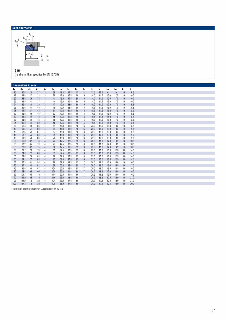
67
G16(l1k shorter than specified by EN 12756)
Seat alternative
d 7
H8
d 6
H11
l6l5
20°
l19
l18
G16 © EagleBurgmann
Dimensions in mmd1 d3 d6 d7 d8 ds l1K l3 l5 l6 l8 l9 l18 l19 b s16 30.0 23 27 3 38 42.5* 32.5 1.5 4 17.5 10.0 – – 1.6 9.018 32.0 27 33 3 39 42.0 30.5 2.0 5 14.0 11.5 15.0 7.0 1.6 10.020 33.5 29 35 3 41 42.0 30.5 2.0 5 14.0 11.5 15.0 7.0 1.6 10.022 36.5 31 37 3 44 42.0 30.5 2.0 5 14.0 11.5 15.0 7.0 1.6 10.024 39.0 33 39 3 47 40.0 28.5 2.0 5 19.5 11.5 15.0 7.0 1.6 8.225 39.6 34 40 3 48 40.0 28.5 2.0 5 19.5 11.5 15.0 7.0 1.6 8.528 42.8 37 43 3 51 42.5 31.0 2.0 5 19.5 11.5 15.0 7.0 1.6 9.030 45.0 39 45 3 53 42.5 31.0 2.0 5 19.5 11.5 15.0 7.0 1.6 8.532 46.0 42 48 3 55 42.5 31.0 2.0 5 19.5 11.5 15.0 7.0 1.6 9.233 48.0 42 48 3 56 42.5 31.0 2.0 5 19.5 11.5 15.0 7.0 1.6 9.235 49.2 44 50 3 58 42.5 31.0 2.0 5 19.5 11.5 15.0 7.0 1.6 9.538 52.3 49 56 4 61 45.0 31.0 2.0 6 22.0 14.0 16.0 8.0 1.6 9.240 55.5 51 58 4 64 45.0 31.0 2.0 6 22.0 14.0 16.0 8.0 1.6 9.243 57.5 54 61 4 67 45.0 31.0 2.0 6 22.0 14.0 16.0 8.0 1.6 9.245 58.7 56 63 4 69 45.0 31.0 2.0 6 22.0 14.0 16.0 8.0 1.6 9.548 61.9 59 66 4 72 45.0 31.0 2.0 6 22.0 14.0 16.0 8.0 1.6 9.250 65.0 62 70 4 74 47.5 32.5 2.5 6 23.0 15.0 17.0 9.5 1.6 10.553 68.2 65 73 4 77 47.5 32.5 2.5 6 23.0 15.0 17.0 9.5 1.6 10.555 70.0 67 75 4 80 47.5 32.5 2.5 6 23.0 15.0 17.0 9.5 1.6 10.058 71.7 70 78 4 83 52.5 37.5 2.5 6 23.0 15.0 18.0 10.5 3.0 14.060 74.6 72 80 4 85 52.5 37.5 2.5 6 23.0 15.0 18.0 10.5 3.0 14.063 79.0 75 83 4 88 52.5 37.5 2.5 6 23.0 15.0 18.0 10.5 3.0 14.065 84.1 77 85 4 95 52.5 37.5 2.5 6 23.0 15.0 18.0 10.5 3.0 14.068 87.3 81 90 4 96 52.5 34.5 2.5 7 26.0 18.0 18.5 11.0 1.6 10.070 87.3 83 92 4 96 60.0 42.0 2.5 7 26.0 18.0 19.0 11.5 3.0 17.075 95.0 88 97 4 104 60.0 42.0 2.5 7 26.0 18.0 19.0 11.5 3.0 16.080 98.4 95 105 4 109 60.0 41.8 3.0 7 26.2 18.2 19.0 11.5 3.0 16.085 104.7 100 110 4 114 60.0 41.8 3.0 7 26.2 18.2 19.0 11.5 3.0 16.090 111.0 105 115 4 119 65.0 46.8 3.0 7 26.2 18.2 20.5 13.0 3.0 21.095 114.0 110 120 4 124 65.0 47.8 3.0 7 25.2 17.2 20.5 13.0 3.0 21.0
100 117.4 115 125 4 129 65.0 47.8 3.0 7 25.2 17.2 20.5 13.0 3.0 20.0
* Installation length is longer than l1k specified by EN 12756
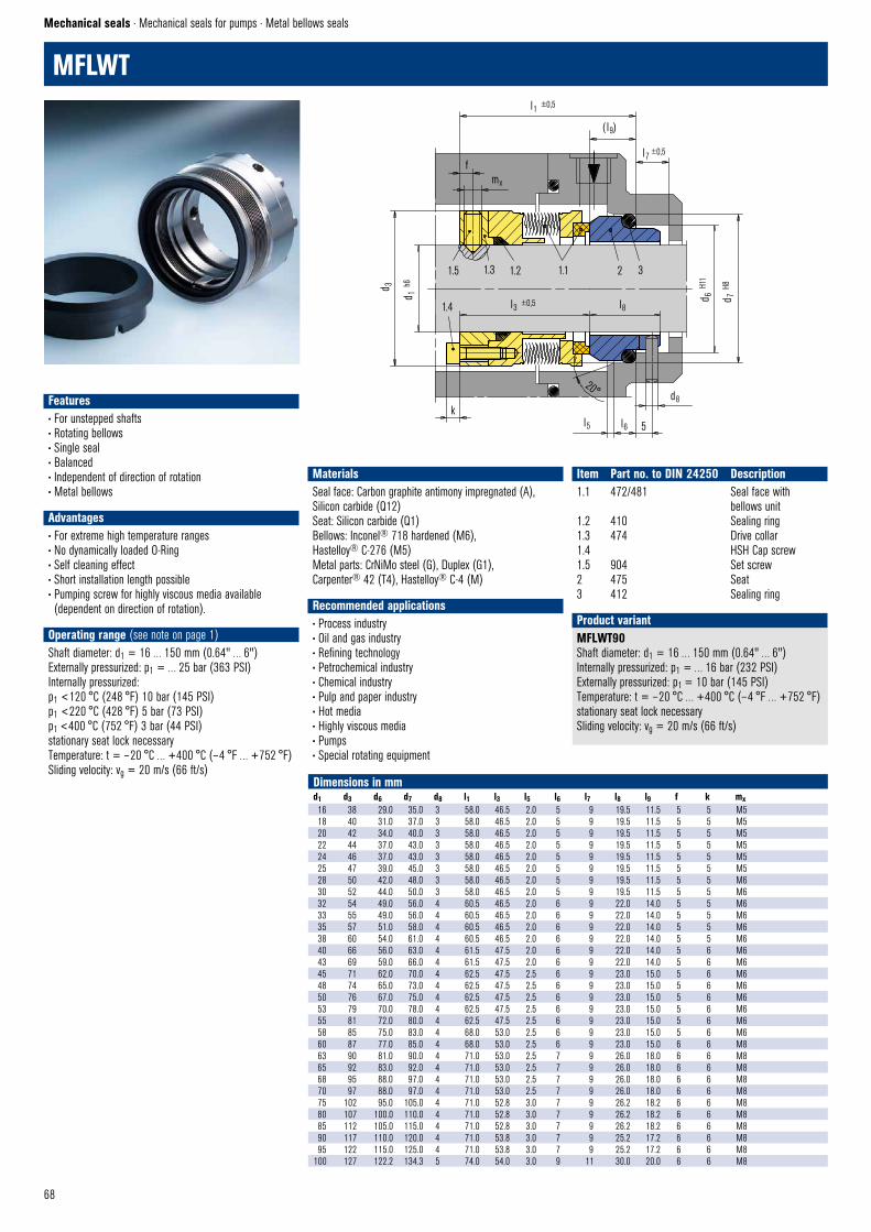
68
MFLWT
Mechanical seals · Mechanical seals for pumps · Metal bellows seals
MFLWT90Shaft diameter: d1 = 16 … 150 mm (0.64" … 6")Internally pressurized: p1 = … 16 bar (232 PSI)Externally pressurized: p1 = 10 bar (145 PSI) Temperature: t = – 20 °C … +400 °C (– 4 °F … +752 °F)stationary seat lock necessarySliding velocity: vg = 20 m/s (66 ft/s)
Product variant
Dimensions in mmd1 d3 d6 d7 d8 l1 l3 l5 l6 l7 l8 l9 f k mx16 38 29.0 35.0 3 58.0 46.5 2.0 5 9 19.5 11.5 5 5 M518 40 31.0 37.0 3 58.0 46.5 2.0 5 9 19.5 11.5 5 5 M520 42 34.0 40.0 3 58.0 46.5 2.0 5 9 19.5 11.5 5 5 M522 44 37.0 43.0 3 58.0 46.5 2.0 5 9 19.5 11.5 5 5 M524 46 37.0 43.0 3 58.0 46.5 2.0 5 9 19.5 11.5 5 5 M525 47 39.0 45.0 3 58.0 46.5 2.0 5 9 19.5 11.5 5 5 M528 50 42.0 48.0 3 58.0 46.5 2.0 5 9 19.5 11.5 5 5 M630 52 44.0 50.0 3 58.0 46.5 2.0 5 9 19.5 11.5 5 5 M632 54 49.0 56.0 4 60.5 46.5 2.0 6 9 22.0 14.0 5 5 M633 55 49.0 56.0 4 60.5 46.5 2.0 6 9 22.0 14.0 5 5 M635 57 51.0 58.0 4 60.5 46.5 2.0 6 9 22.0 14.0 5 5 M638 60 54.0 61.0 4 60.5 46.5 2.0 6 9 22.0 14.0 5 5 M640 66 56.0 63.0 4 61.5 47.5 2.0 6 9 22.0 14.0 5 6 M643 69 59.0 66.0 4 61.5 47.5 2.0 6 9 22.0 14.0 5 6 M645 71 62.0 70.0 4 62.5 47.5 2.5 6 9 23.0 15.0 5 6 M648 74 65.0 73.0 4 62.5 47.5 2.5 6 9 23.0 15.0 5 6 M650 76 67.0 75.0 4 62.5 47.5 2.5 6 9 23.0 15.0 5 6 M653 79 70.0 78.0 4 62.5 47.5 2.5 6 9 23.0 15.0 5 6 M655 81 72.0 80.0 4 62.5 47.5 2.5 6 9 23.0 15.0 5 6 M658 85 75.0 83.0 4 68.0 53.0 2.5 6 9 23.0 15.0 5 6 M660 87 77.0 85.0 4 68.0 53.0 2.5 6 9 23.0 15.0 6 6 M863 90 81.0 90.0 4 71.0 53.0 2.5 7 9 26.0 18.0 6 6 M865 92 83.0 92.0 4 71.0 53.0 2.5 7 9 26.0 18.0 6 6 M868 95 88.0 97.0 4 71.0 53.0 2.5 7 9 26.0 18.0 6 6 M870 97 88.0 97.0 4 71.0 53.0 2.5 7 9 26.0 18.0 6 6 M875 102 95.0 105.0 4 71.0 52.8 3.0 7 9 26.2 18.2 6 6 M880 107 100.0 110.0 4 71.0 52.8 3.0 7 9 26.2 18.2 6 6 M885 112 105.0 115.0 4 71.0 52.8 3.0 7 9 26.2 18.2 6 6 M890 117 110.0 120.0 4 71.0 53.8 3.0 7 9 25.2 17.2 6 6 M895 122 115.0 125.0 4 71.0 53.8 3.0 7 9 25.2 17.2 6 6 M8
100 127 122.2 134.3 5 74.0 54.0 3.0 9 11 30.0 20.0 6 6 M8
Features• For unstepped shafts• Rotating bellows• Single seal• Balanced• Independent of direction of rotation• Metal bellows
Advantages• For extreme high temperature ranges• No dynamically loaded O-Ring • Self cleaning effect• Short installation length possible• Pumping screw for highly viscous media available (dependent on direction of rotation).
Operating range (see note on page 1)Shaft diameter: d1 = 16 … 150 mm (0.64" … 6")Externally pressurized: p1 = … 25 bar (363 PSI) Internally pressurized: p1 <120 °C (248 °F) 10 bar (145 PSI)p1 <220 °C (428 °F) 5 bar (73 PSI)p1 <400 °C (752 °F) 3 bar (44 PSI)stationary seat lock necessaryTemperature: t = – 20 °C … +400 °C (– 4 °F … +752 °F)Sliding velocity: vg = 20 m/s (66 ft/s)
Materials Seal face: Carbon graphite antimony impregnated (A), Silicon carbide (Q12)Seat: Silicon carbide (Q1) Bellows: Inconel® 718 hardened (M6),Hastelloy® C-276 (M5) Metal parts: CrNiMo steel (G), Duplex (G1), Carpenter® 42 (T4), Hastelloy® C-4 (M)
Recommended applications• Process industry• Oil and gas industry• Refining technology• Petrochemical industry• Chemical industry• Pulp and paper industry• Hot media• Highly viscous media• Pumps• Special rotating equipment
Item Part no. to DIN 24250 Description1.1 472/481 Seal face with bellows unit1.2 410 Sealing ring1.3 474 Drive collar1.4 HSH Cap screw1.5 904 Set screw2 475 Seat3 412 Sealing ring
1.5 1.3 1.2 1.1 2 3
1.4 l3 ±0,5 l8
d 3
d 1 h6
l1 ±0,5
( l9)
l7 ±0,5
d 6 H1
1
d 7 H8
20°
l5 l6 5
d8 k
fmx
MFLWT80 © EagleBurgmann
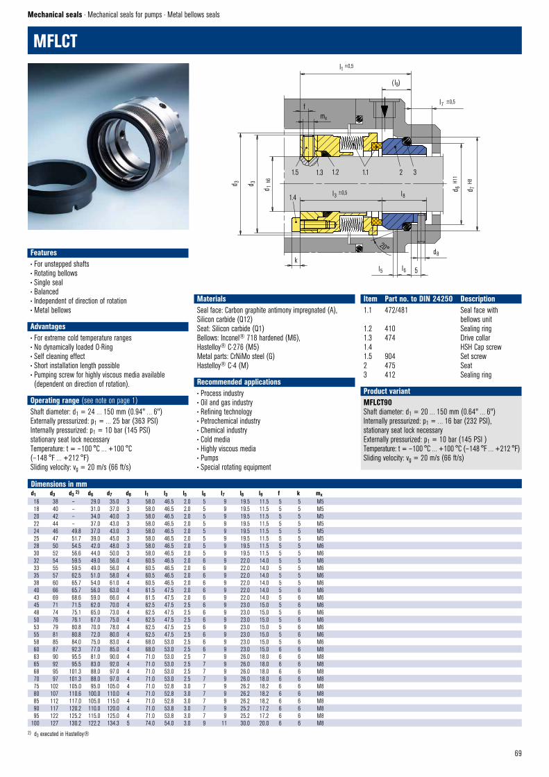
69
Features• For unstepped shafts• Rotating bellows• Single seal• Balanced• Independent of direction of rotation• Metal bellows
Advantages• For extreme cold temperature ranges• No dynamically loaded O-Ring • Self cleaning effect• Short installation length possible• Pumping screw for highly viscous media available (dependent on direction of rotation).
Operating range (see note on page 1)Shaft diameter: d1 = 24 … 150 mm (0.94" … 6")Externally pressurized: p1 = … 25 bar (363 PSI)Internally pressurized: p1 = 10 bar (145 PSI)stationary seat lock necessaryTemperature: t = – 100 °C … +100 °C (– 148 °F … +212 °F)Sliding velocity: vg = 20 m/s (66 ft/s)
Materials Seal face: Carbon graphite antimony impregnated (A), Silicon carbide (Q12)Seat: Silicon carbide (Q1) Bellows: Inconel® 718 hardened (M6),Hastelloy® C-276 (M5) Metal parts: CrNiMo steel (G)Hastelloy® C-4 (M)
Recommended applications• Process industry• Oil and gas industry• Refining technology• Petrochemical industry• Chemical industry• Cold media• Highly viscous media• Pumps• Special rotating equipment
Item Part no. to DIN 24250 Description1.1 472/481 Seal face with bellows unit1.2 410 Sealing ring1.3 474 Drive collar1.4 HSH Cap screw1.5 904 Set screw2 475 Seat3 412 Sealing ring
1.5 1.3 1.2 1.1 2 3
1.4 l3 ±0,5 l8
d 3 d 3
d 1 h6
l1 ±0,5
( l9)
kl5 l6 5
d8
20°
fmx
l7 ±0,5
d 6 H
11
d 7 H
8
MFLCT80 © EagleBurgmann
MFLCT
Mechanical seals · Mechanical seals for pumps · Metal bellows seals
MFLCT90Shaft diameter: d1 = 20 … 150 mm (0.64" … 6")Internally pressurized: p1 = … 16 bar (232 PSI), stationary seat lock necessaryExternally pressurized: p1 = 10 bar (145 PSI ) Temperature: t = – 100 °C … +100 °C (– 148 °F … +212 °F)Sliding velocity: vg = 20 m/s (66 ft/s)
Product variant
Dimensions in mmd1 d3 d3 2) d6 d7 d8 l1 l3 l5 l6 l7 l8 l9 f k mx16 38 – 29.0 35.0 3 58.0 46.5 2.0 5 9 19.5 11.5 5 5 M518 40 – 31.0 37.0 3 58.0 46.5 2.0 5 9 19.5 11.5 5 5 M520 42 – 34.0 40.0 3 58.0 46.5 2.0 5 9 19.5 11.5 5 5 M522 44 – 37.0 43.0 3 58.0 46.5 2.0 5 9 19.5 11.5 5 5 M524 46 49.8 37.0 43.0 3 58.0 46.5 2.0 5 9 19.5 11.5 5 5 M525 47 51.7 39.0 45.0 3 58.0 46.5 2.0 5 9 19.5 11.5 5 5 M528 50 54.5 42.0 48.0 3 58.0 46.5 2.0 5 9 19.5 11.5 5 5 M630 52 56.6 44.0 50.0 3 58.0 46.5 2.0 5 9 19.5 11.5 5 5 M632 54 59.5 49.0 56.0 4 60.5 46.5 2.0 6 9 22.0 14.0 5 5 M633 55 59.5 49.0 56.0 4 60.5 46.5 2.0 6 9 22.0 14.0 5 5 M635 57 62.5 51.0 58.0 4 60.5 46.5 2.0 6 9 22.0 14.0 5 5 M638 60 65.7 54.0 61.0 4 60.5 46.5 2.0 6 9 22.0 14.0 5 5 M640 66 65.7 56.0 63.0 4 61.5 47.5 2.0 6 9 22.0 14.0 5 6 M643 69 68.6 59.0 66.0 4 61.5 47.5 2.0 6 9 22.0 14.0 5 6 M645 71 71.5 62.0 70.0 4 62.5 47.5 2.5 6 9 23.0 15.0 5 6 M648 74 75.1 65.0 73.0 4 62.5 47.5 2.5 6 9 23.0 15.0 5 6 M650 76 76.1 67.0 75.0 4 62.5 47.5 2.5 6 9 23.0 15.0 5 6 M653 79 80.8 70.0 78.0 4 62.5 47.5 2.5 6 9 23.0 15.0 5 6 M655 81 80.8 72.0 80.0 4 62.5 47.5 2.5 6 9 23.0 15.0 5 6 M658 85 84.0 75.0 83.0 4 68.0 53.0 2.5 6 9 23.0 15.0 5 6 M660 87 92.3 77.0 85.0 4 68.0 53.0 2.5 6 9 23.0 15.0 6 6 M863 90 95.5 81.0 90.0 4 71.0 53.0 2.5 7 9 26.0 18.0 6 6 M865 92 95.5 83.0 92.0 4 71.0 53.0 2.5 7 9 26.0 18.0 6 6 M868 95 101.3 88.0 97.0 4 71.0 53.0 2.5 7 9 26.0 18.0 6 6 M870 97 101.3 88.0 97.0 4 71.0 53.0 2.5 7 9 26.0 18.0 6 6 M875 102 105.0 95.0 105.0 4 71.0 52.8 3.0 7 9 26.2 18.2 6 6 M880 107 110.6 100.0 110.0 4 71.0 52.8 3.0 7 9 26.2 18.2 6 6 M885 112 117.0 105.0 115.0 4 71.0 52.8 3.0 7 9 26.2 18.2 6 6 M890 117 120.2 110.0 120.0 4 71.0 53.8 3.0 7 9 25.2 17.2 6 6 M895 122 125.2 115.0 125.0 4 71.0 53.8 3.0 7 9 25.2 17.2 6 6 M8
100 127 130.2 122.2 134.3 5 74.0 54.0 3.0 9 11 30.0 20.0 6 6 M82) d3 executed in Hastelloy®
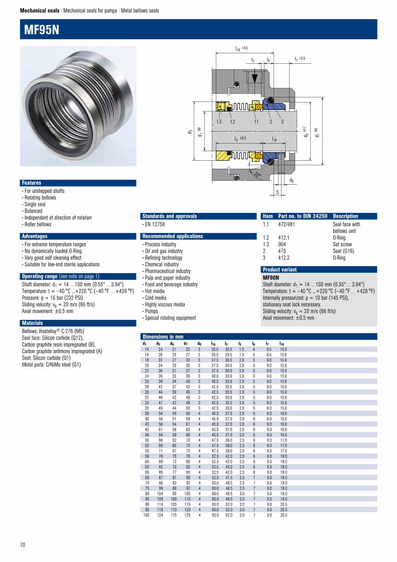
70
MF95N
Mechanical seals · Mechanical seals for pumps · Metal bellows seals
Dimensions in mmd1 d3 d6 d7 d8 l1k l3 l5 l6 l7 l1814 24 21 25 3 35.0 30.5 1.5 4 8.5 15.016 26 23 27 3 35.0 29.5 1.5 4 8.5 15.018 32 27 33 3 37.5 30.5 2.0 5 9.0 15.020 34 29 35 3 37.5 30.5 2.0 5 9.0 15.022 36 31 37 3 37.5 30.5 2.0 5 9.0 15.024 39 33 39 3 40.0 33.0 2.0 5 9.0 15.025 39 34 40 3 40.0 33.0 2.0 5 9.0 15.028 42 37 43 3 42.5 35.5 2.0 5 9.0 15.030 44 39 45 3 42.5 35.5 2.0 5 9.0 15.032 46 42 48 3 42.5 35.5 2.0 5 9.0 15.033 47 42 48 3 42.5 35.5 2.0 5 9.0 15.035 49 44 50 3 42.5 35.5 2.0 5 9.0 15.038 54 49 56 4 45.0 37.0 2.0 6 9.0 16.040 56 51 58 4 45.0 37.0 2.0 6 9.0 16.043 58 54 61 4 45.0 37.0 2.0 6 9.0 16.045 61 56 63 4 45.0 37.0 2.0 6 9.0 16.048 64 59 66 4 45.0 37.0 2.0 6 9.0 16.050 66 62 70 4 47.5 38.0 2.5 6 9.0 17.053 69 65 73 4 47.5 38.0 2.5 6 9.0 17.055 71 67 75 4 47.5 38.0 2.5 6 9.0 17.058 78 70 78 4 52.5 42.0 2.5 6 9.0 18.060 80 72 80 4 52.5 42.0 2.5 6 9.0 18.063 83 75 83 4 52.5 42.0 2.5 6 9.0 18.065 85 77 85 4 52.5 42.0 2.5 6 9.0 18.068 87 81 90 4 52.5 41.5 2.5 7 9.0 18.570 90 83 92 4 60.0 48.5 2.5 7 9.0 19.075 99 88 97 4 60.0 48.5 2.5 7 9.0 19.080 104 95 105 4 60.0 48.5 3.0 7 9.0 19.085 109 100 110 4 60.0 48.5 3.0 7 9.0 19.090 114 105 115 4 65.0 52.0 3.0 7 9.0 20.595 119 110 120 4 65.0 52.0 3.0 7 9.0 20.5
100 124 115 125 4 65.0 52.0 3.0 7 9.0 20.5
MF90NShaft diameter: d1 = 14 … 100 mm (0.55" … 3.94")Temperature: t = – 40 °C ...+220 °C (– 40 °F … +428 °F)Internally pressurized: p = 10 bar (145 PSI), stationary seat lock necessary.Sliding velocity: vg = 20 m/s (66 ft/s)Axial movement: ±0.5 mm
Product variant
Features• For unstepped shafts• Rotating bellows• Single seal• Balanced• Independent of direction of rotation• Roller bellows
Advantages• For extreme temperature ranges• No dynamically loaded O-Ring • Very good self cleaning effect• Suitable for low-end sterile applications
Operating range (see note on page 1)Shaft diameter: d1 = 14 … 100 mm (0.55" … 3.94")Temperature: t = – 40 °C ...+220 °C (– 40 °F … +428 °F)Pressure: p = 16 bar (232 PSI)Sliding velocity: vg = 20 m/s (66 ft/s)Axial movement: ±0.5 mm
MaterialsBellows: Hastelloy® C-276 (M5) Seal face: Silicon carbide (Q12),Carbon graphite resin impregnated (B),Carbon graphite antimony impregnated (A)Seat: Silicon carbide (Q1)Metal parts: CrNiMo steel (G1)
Standards and approvals• EN 12756
Recommended applications• Process industry• Oil and gas industry• Refining technology• Chemical industry• Pharmaceutical industry• Pulp and paper industry• Food and beverage industry• Hot media• Cold media• Highly viscous media• Pumps• Special rotating equipment
Item Part no. to DIN 24250 Description1.1 472/481 Seal face with bellows unit1.2 412.1 O-Ring1.3 904 Set screw2 475 Seat (G16)3 412.2 O-Ring
1.3 1.2 1.1 2 3
5
l3 ±0,5 l18
d 1 h
6
d 3
20° d8
d 6 H
11
d 7 H
8
l1K +0,5
l5 l6 l7 +0,5
MF95N © EagleBurgmann
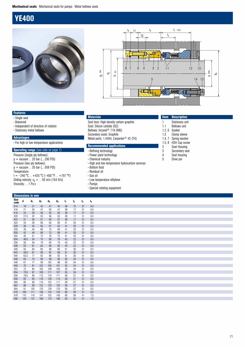
71
1.1 1.2 1.3
1.4 1.5
8 7 6 4 3 2
5
d m
ax
d 4
YE400 © EagleBurgmann
d 3 m
in
d 1 h
7
d 2
l1 ±0,3l4l2
l31110
YE400
Mechanical seals · Mechanical seals for pumps · Metal bellows seals
Dimensions in mmSizecode d d1 d2 d3 d4 l1 l2 l3 l4
X14 18 21 42 47 44 36 15 31 6.3X16 21 26 47 50 47 38 17 31 6.3X18 24 29 50 53 50 38 17 31 6.3X20 27.5 32 53 56 53 38 17 31 6.3X22 31 36 57 60 57 38 17 31 6.3X24 33 39 60 64 60 41 20 31 6.3X26 36 42 63 67 63 41 20 31 6.3X28 39 45 66 70 66 41 20 31 6.3X30 42 48 69 73 69 41 20 31 6.3X32 45 51 72 76 72 41 20 31 6.3X34 46.5 54 75 80 76 43 22 31 6.3X36 50 58 79 83 79 43 22 31 6.3X38 53 61 82 86 82 43 22 31 6.3X40 55 64 85 89 85 51 30 31 6.3X42 58.5 67 89 92 88 51 30 31 6.3X44 62.5 71 92 96 92 51 30 31 6.3X46 64 74 96 99 95 55 34 31 6.3X48 67 77 99 102 98 55 34 31 6.3X50 70 81 102 105 101 55 34 31 6.3X52 73 84 105 108 104 55 34 31 6.3X54 75.5 87 109 111 107 55 34 31 6.3X56 78.5 90 113 116 111 58 37 31 6.3X58 82 93 116 120 114 58 37 31 6.3X60 85 96 119 122 117 58 37 31 6.3X62 88 99 122 125 120 58 37 31 6.3X64 91 103 125 128 123 58 37 31 6.3X70 100 111 138 142 134 60 39 31 6.3X78 110 116 147 152 145 60 39 41 7.5X90 129 137 168 173 166 63 42 41 7.5
Features• Single seal• Balanced• Independent of direction of rotation• Stationary metal bellows
Advantages• For high or low temperature applications
Operating range (see note on page 1)Pressure (single ply bellows): p = vacuum … 20 bar (... 290 PSI)Pressure (two ply bellows): p = vacuum … 35 bar (... 508 PSI)Temperature: t = – 240 °C … +425 °C (– 400 °F … +797 °F)Sliding velocity: vg = … 50 m/s (164 ft/s)Viscosity: … 1 Pa·s
MaterialsSeal face: High density carbon graphiteSeat: Silicon carbide (Q2)Bellows: Inconel® 718 (M6)Secondary seals: GraphiteMetal parts: 1.4404, Carpenter® 42 (T4)
Recommended applications• Refining technology• Power plant technology• Chemical industry• High and low temperature hydrocarbon services• Bottom fluid • Residual oil • Gas oil• Low temperature ethylene• Pumps• Special rotating equipment
Item Description1 Stationary unit1.1 Bellows unit1.2, 6 Gasket1.3 Clamp sleeve1.4, 7 Spring washer1.5, 8 HSH Cap screw2 Seat Housing3 Secondary seal4 Seat housing5 Drive pin
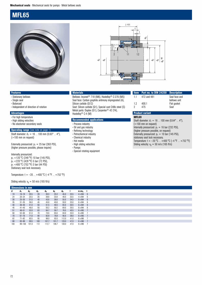
72
MFL65
Mechanical seals · Mechanical seals for pumps · Metal bellows seals
Dimensions in mmd d1 d2 d3 d4 d5 d6 l n x mx t 19 16–19 20.5 29 30.3 25.3 45.0 33.5 4 x M4 6 24 20–24 25.5 35 38.8 33.8 49.0 33.5 4 x M4 6 30 25–30 31.5 40 43.6 38.6 55.0 34.5 6 x M4 6 35 31–35 36.0 45 45.8 40.8 59.0 33.0 6 x M4 6 40 36–40 41.0 50 51.5 46.5 65.0 30.5 6 x M4 6 45 41–45 46.0 55 55.2 50.2 69.0 35.5 6 x M4 6 51 46–51 52.0 63 64.7 59.7 76.5 40.5 6 x M5 7 60 52–60 61.0 70 70.6 65.6 84.0 32.0 6 x M5 7 70 61–70 71.0 80 82.8 76.8 95.0 38.0 6 x M5 7 82 71–82 83.5 95 98.0 92.0 112.0 41.0 6 x M6 7 88 83–88 89.5 100 107.7 101.7 120.0 47.0 6 x M6 7
100 89–100 101.0 112 112.7 106.7 130.0 47.0 6 x M6 7
MFL69Shaft diameter: d1 = 16 … 100 mm (0.64" … 4"), (>100 mm on request)Internally pressurized: p1 = 16 bar (232 PSI), (higher pressure possible, on request)Externally pressurized: p1 = 10 bar (145 PSI), stationary seat lock necessary. Temperature: t = – 20 °C … +400 °C (– 4 °F … +752 °F) Sliding velocity: vg = 50 m/s (165 ft/s)
Product variant
Features• Stationary bellows• Single seal• Balanced• Independent of direction of rotation
Advantages• For high temperature• High sliding velocities• No elastomer secondary seals
Operating range (see note on page 1)Shaft diameter: d1 = 16 … 100 mm (0.63" … 4"), (>100 mm on request)
Externally pressurized: p1 = 25 bar (363 PSI), (higher pressure possible, please inquire)
Internally pressurized: p1 <120 °C (248 °F) 10 bar (145 PSI),p1 <220 °C (428 °F) 5 bar (72 PSI),p1 <400 °C (752 °F) 3 bar (44 PSI) Stationary seat lock necessary
Temperature: t = – 20 … +400 °C (– 4 °F … +752 °F)
Sliding velocity: vg = 50 m/s (165 ft/s)
Materials Bellows: Inconel® 718 (M6), Hastelloy® C-276 (M5) Seal face: Carbon graphite antimony impregnated (A), Silicon carbide (Q12) Seat: Silicon carbide (Q1), Special cast CrMo steel (S) Metal parts: Duplex (G1), Carpenter® 42 (T4), Hastelloy® C-4 (M)
Recommended applications• Process industry• Oil and gas industry• Refining technology• Petrochemical industry• Chemical industry• Hot media• High sliding velocities• Pumps• Special rotating equipment
Item Part no. to DIN 24250 Description1.1 472 und 481 Seal face and bellows unit1.2 400.1 Flat gasket2 475 Seat
2 1.1 1.2
d 4 d 5
l ±0,5
t1
mx
d 1 d 2 d 3 d 6 H8
MFL65 © EagleBurgmann

73
3 2 1.1 1.2 1.3
4 5 1.6 1.4
1.56
d 3 m
in
d 2
30°
32
d h7
d 1 H7
30°
0,5 2
l1 l2
l
EK777
Mechanical seals · Mechanical seals for pumps · Engineered seals
Dimensions in mm d d1 d2 d3 l l1 l220 50 40 46 56 27 2925 54 46 52 56 27 2930 60 51 57 56 27 2935 64 56 62 56 27 2940 72 63 69 62 31 3145 76 68 74 62 31 3150 85 76 82 66 33 3355 90 82 88 66 33 3360 100 90 96 66 33 3365 105 93 99 66 33 3370 110 99 105 66 33 3375 115 104 110 66 33 3380 120 111 117 68 35 3385 127 117 123 68 35 3390 132 120 126 68 35 3395 140 129 135 68 35 33
100 145 132 138 68 35 33105 150 137 143 68 35 33110 162 144 150 68 35 33
Configuration exampleacc. to API 682 (1CW-FL)
Product variant
Features• Single seal• Balanced• Independent of direction of rotation• Stationary multiple springs• Compact construction• API 682 (Type A) compliant seal • Angled set screw drive configuration ensures precise vertical alignment of rotary seat
• Distributed flush ensures even cooling flow to seal faces
Operating range (see note on page 1)Pressure (product seal): p = vacuum … 60 bar (… 870 PSI)Temperature: t = – 20 °C … +200 °C (– 4 °F … +392 °F)Sliding velocity: vg = 50 m/s (164 ft/s)Viscosity: … 300 mPa·sSolids content: … 0.3 %
MaterialsSeal face: High density carbon graphiteSeat: Silicon carbide (Q1, Q2)Secondary seals: FKM (V)Metal parts: 1.4401 (G), 1.4301 (F)
Standards and approvals• API 682/ISO 21049
Recommended applications• Power plant technology• Oil and gas industry• LPG• Hot water• High pressure pumps• Compressors • Blowers• High speed pumps • Boiler feed pumps • LPG
Item Description1.1 Seal face1.2, 1.5, 3, 5 O-Ring1.3 Adapter1.4 Spring1.6 Snap ring2 Seat4 Drive collar6 Set screw
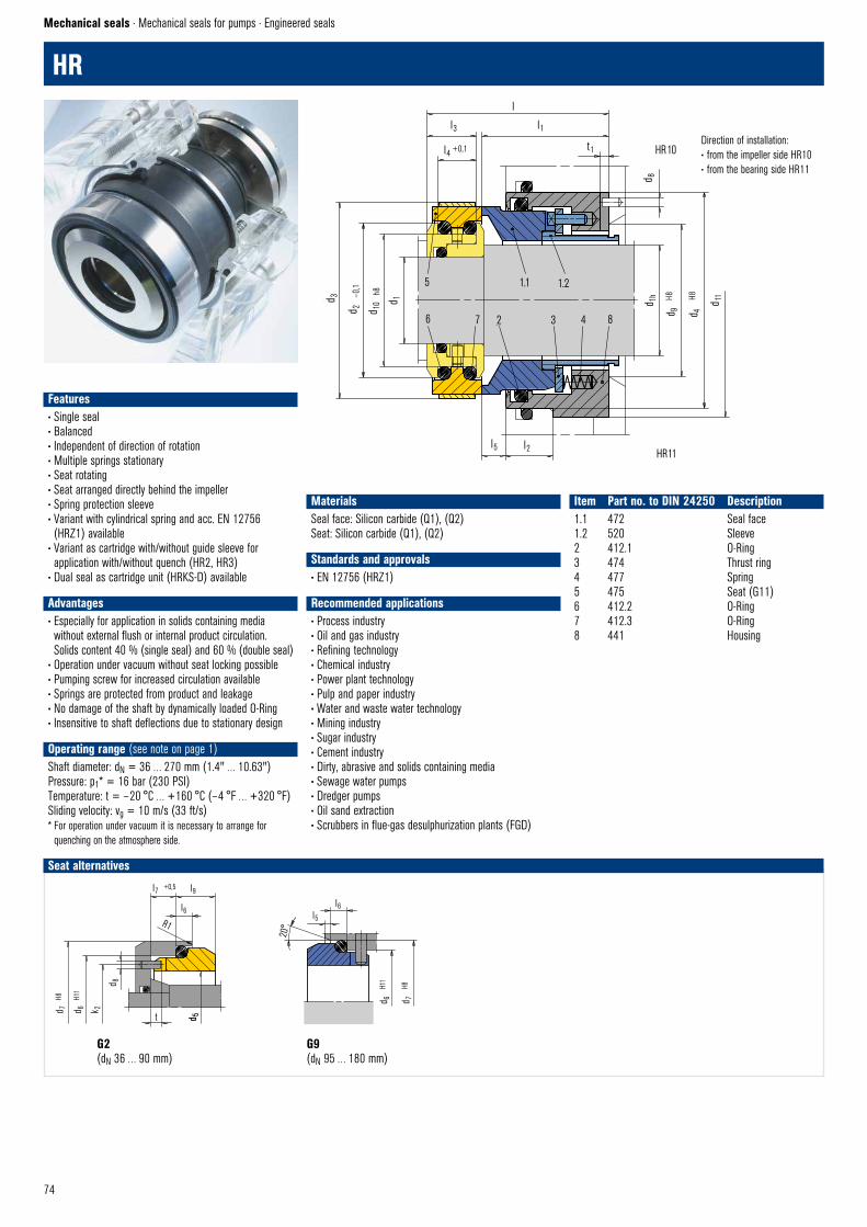
74
1.1 1.25
6 7 2 3 4 8d 3
d 10 d 1
d 2–0
,1
h8
d 11
d 4
H8d 9
H8d 1h
HR10
d 8
l
l1
t1
l3
l4
HR11l5 l2
HR © EagleBurgmann
+0,1
G2(dN 36 … 90 mm)
G9(dN 95 … 180 mm)
Seat alternatives
d 7
H8
d 6
H11
l6l5
20°
G9 © EagleBurgmann
Direction of installation:• from the impeller side HR10• from the bearing side HR11
HR
Mechanical seals · Mechanical seals for pumps · Engineered seals
d 7
H8
d 6
H11
k 2
t d 5
l7 +0,5 l9
l6
d 8
d 5
R1
G2 © EagleBurgmann
Features• Single seal• Balanced• Independent of direction of rotation• Multiple springs stationary• Seat rotating• Seat arranged directly behind the impeller• Spring protection sleeve• Variant with cylindrical spring and acc. EN 12756 (HRZ1) available
• Variant as cartridge with/without guide sleeve for application with/without quench (HR2, HR3)
• Dual seal as cartridge unit (HRKS-D) available
Advantages• Especially for application in solids containing media without external flush or internal product circulation. Solids content 40 % (single seal) and 60 % (double seal)
• Operation under vacuum without seat locking possible• Pumping screw for increased circulation available• Springs are protected from product and leakage• No damage of the shaft by dynamically loaded O-Ring• Insensitive to shaft deflections due to stationary design
Operating range (see note on page 1)Shaft diameter: dN = 36 … 270 mm (1.4" … 10.63")Pressure: p1* = 16 bar (230 PSI)Temperature: t = – 20 °C … +160 °C (– 4 °F … +320 °F)Sliding velocity: vg = 10 m/s (33 ft/s)* For operation under vacuum it is necessary to arrange for
quenching on the atmosphere side.
MaterialsSeal face: Silicon carbide (Q1), (Q2)Seat: Silicon carbide (Q1), (Q2)
Standards and approvals• EN 12756 (HRZ1)
Recommended applications• Process industry• Oil and gas industry• Refining technology• Chemical industry• Power plant technology• Pulp and paper industry• Water and waste water technology• Mining industry• Sugar industry• Cement industry• Dirty, abrasive and solids containing media• Sewage water pumps• Dredger pumps• Oil sand extraction• Scrubbers in flue-gas desulphurization plants (FGD)
Item Part no. to DIN 24250 Description1.1 472 Seal face1.2 520 Sleeve2 412.1 O-Ring3 474 Thrust ring4 477 Spring5 475 Seat (G11)6 412.2 O-Ring7 412.3 O-Ring8 441 Housing
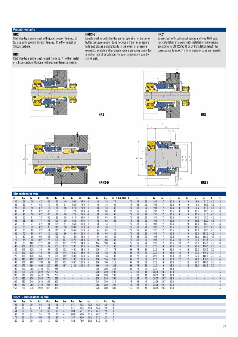
75
HR2Cartridge-type single seal with guide sleeve (Item no. 2) for use with quench. Insert (Item no. 1) either metal or Silicon carbide.
HR3Cartridge-type single seal. Insert (Item no. 1) either metal or silicon carbide. Optional without maintenance rinsing.
HRKS-DDouble seal in cartridge design for operation in barrier or buffer pressure mode (does not open if barrier pressure fails and closes automatically in the event of pressure reversal), available alternatively with a pumping screw for a higher rate of circulation. Torque transmission e. g. by shrink disk.
HRZ1Single seal with cylindrical spring and type G76 seat. For installation in covers with installation dimensions according to EN 12756 B or U. Installation length l11 corresponds to max. l1k. Intermediate sizes on request.
Product variants
HRZ1 – Dimensions in mmdN d1h d1 d11 d12 d13 d14 l10 l11 l12 l13 l15 l1635 33 20 56 42 48 3 57.7 49.2 15.0 42.7 2.0 543 39 27 67 54 61 4 57.7 49.2 15.0 42.7 2.0 654 50 35 78 65 73 4 59.8 52.1 15.5 44.3 2.5 666 60 47 91 77 85 4 66.0 58.0 16.5 49.5 2.5 677 72 55 103 88 97 4 74.5 66.0 17.5 57.0 2.5 7
100 90 70 125 110 120 4 82.0 73.0 21.0 61.0 3.0 7
Dimensions in mmd1 d1h dN d2 d3 d4 d5 d6 d7 d8 d9 d10 d11 + 0.2 min. l l1 l2 l3 l4 l5 l6 l7 l9 k2 t t120 28 36 47.1 65 70 46 56.0 63.0 4 40 38 75 75 53 20 19.5 17 10.5 6 9 8.0 51.0 4.5 325 33 41 52.1 70 75 51 62.0 70.0 4 45 43 80 75 53 20 19.5 17 10.5 6 9 9.5 56.5 4.5 328 38 46 57.1 75 80 56 67.0 75.0 4 50 48 85 75 53 20 19.5 17 10.5 6 9 9.5 61.5 4.5 333 43 51 62.1 80 85 61 72.0 80.0 4 55 53 90 75 53 20 19.5 17 10.5 6 9 10.5 66.5 4.5 338 48 56 67.1 85 90 66 77.0 85.0 4 60 58 95 75 53 20 19.5 17 10.5 6 9 10.5 71.5 4.5 343 53 61 72.1 90 95 69 81.0 90.0 4 65 63 100 75 53 20 19.5 17 10.5 7 9 11.0 75.0 4.5 348 58 66 77.1 95 100 76 88.0 97.0 4 70 68 105 75 53 20 19.5 17 10.5 7 9 11.5 82.0 4.5 353 63 71 82.1 101 105 81 95.0 105.0 4 75 73 110 75 53 20 19.5 17 10.5 7 9 11.5 88.0 4.5 355 65 75 87.1 106 110 86 100.0 110.0 4 79 78 115 75 53 20 19.5 17 10.5 7 9 11.5 93.0 4.5 360 70 80 92.1 111 115 91 105.0 115.0 4 84 83 120 75 53 20 19.5 17 10.5 7 9 13.0 98.0 4.5 365 75 85 97.1 116 120 96 110.0 120.0 4 89 88 125 75 53 20 19.5 17 10.5 7 9 13.0 103.0 4.5 370 80 90 102.1 121 125 101 115.0 125.0 4 94 93 130 75 53 20 19.5 17 10.5 7 9 13.0 108.0 4.5 375 85 95 107.1 126 130 107 122.2 134.3 5 99 98 135 75 53 20 19.5 17 10.5 10 12 20.0 114.5 7.0 380 90 100 112.1 131 135 107 122.2 134.3 5 104 103 140 75 53 20 19.5 17 10.5 10 12 20.0 114.5 7.0 390 100 110 126.1 147 155 117 136.2 148.3 5 116 117 163 98 73 30 22.0 19 16.0 10 12 20.0 126.5 7.0 4
100 110 120 136.1 157 165 132 146.2 158.3 5 126 127 173 98 73 30 22.0 19 16.0 10 12 20.0 139.0 7.0 4110 120 130 145.1 167 175 142 156.2 168.3 5 136 136 183 98 73 30 22.0 19 16.0 10 12 20.0 149.0 7.0 4120 130 140 154.1 177 185 152 168.2 180.3 5 146 145 193 98 73 30 22.0 19 16.0 10 12 22.0 160.0 7.0 4130 140 150 163.9 188 195 162 178.2 190.3 5 156 155 203 98 73 30 22.0 19 16.0 12 12 24.0 170.0 7.0 4140 150 160 174.9 189 205 172 188.2 200.3 5 166 166 213 98 73 30 22.0 19 16.0 12 12 24.0 180.0 7.0 4160 170 180 193.9 220 230 187 212.5 224.3 5 186 185 238 98 73 30 22.0 19 16.0 12 12 28.0 199.5 7.0 4180 190 200 213.9 240 255 – – – – 206 205 265 98 73 30 22.0 19 16.0 – – – – – 4190 200 210 231.9 255 270 – – – – 218 220 280 115 83 40 28.35 24.7 19.0 – – – – – 5200 210 220 241.9 265 280 – – – – 228 230 290 115 83 40 28.35 24.7 19.0 – – – – – 5210 220 230 251.9 275 290 – – – – 238 240 300 115 83 40 28.35 24.7 19.0 – – – – – 5220 230 240 261.9 285 300 – – – – 248 250 310 115 83 40 28.35 24.7 19.0 – – – – – 5230 240 250 271.9 295 310 – – – – 258 260 320 115 83 40 28.35 24.7 19.0 – – – – – 5250 260 270 291.9 315 330 – – – – 278 280 340 115 83 40 28.35 24.7 19.0 – – – – – 5
2 1
d 1 d N d 1h
HR2 © EagleBurgmann
d 1 d N d 1h 1
HR3 © EagleBurgmann
l10
l12 l13
l15 l16
d 1h
max
d 12
H11
d 13
H8
d14
5l11
d 11
d 1 d N
5 1.1 8
3 426 7
HRZ1 © EagleBurgmann
HR2
HRKS-D
HR3
HRZ1
5 1.1 2 1.2
7 3 46
d 3 d 1
HRK – D © EagleBurgmann
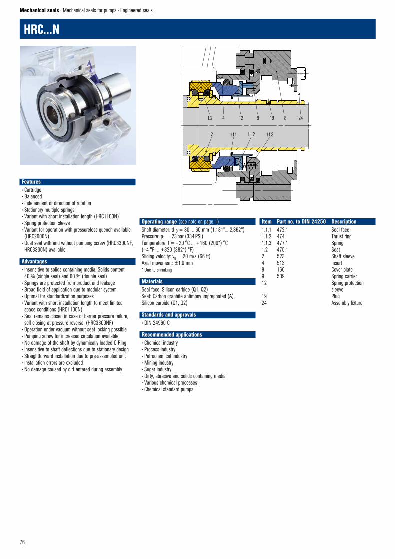
76
HRC...N
Mechanical seals · Mechanical seals for pumps · Engineered seals
Features• Cartridge• Balanced• Independent of direction of rotation• Stationary multiple springs • Variant with short installation length (HRC1100N)• Spring protection sleeve• Variant for operation with pressureless quench available (HRC2000N)
• Dual seal with and without pumping screw (HRC3300NF, HRC3300N) available
Advantages• Insensitive to solids containing media. Solids content 40 % (single seal) and 60 % (double seal)
• Springs are protected from product and leakage• Broad field of application due to modular system • Optimal for standardization purposes• Variant with short installation length to meet limited space conditions (HRC1100N)
• Seal remains closed in case of barrier pressure failure, self-closing at pressure reversal (HRC3300NF)
• Operation under vacuum without seat locking possible• Pumping screw for increased circulation available• No damage of the shaft by dynamically loaded O-Ring• Insensitive to shaft deflections due to stationary design• Straightforward installation due to pre-assembled unit• Installation errors are excluded• No damage caused by dirt entered during assembly
Operating range (see note on page 1)Shaft diameter: d10 = 30 … 60 mm (1,181"... 2,362")Pressure: p1 = 23 bar (334 PSI)Temperature: t = – 20 °C … +160 (200*) °C (– 4 °F … +320 (382*) °F)Sliding velocity: vg = 20 m/s (66 ft)Axial movement: ±1.0 mm* Due to shrinking
MaterialsSeal face: Silicon carbide (Q1, Q2) Seat: Carbon graphite antimony impregnated (A), Silicon carbide (Q1, Q2)
Standards and approvals• DIN 24960 C
Recommended applications• Chemical industry• Process industry• Petrochemical industry• Mining industry• Sugar industry• Dirty, abrasive and solids containing media• Various chemical processes• Chemical standard pumps
Item Part no. to DIN 24250 Description1.1.1 472.1 Seal face1.1.2 474 Thrust ring1.1.3 477.1 Spring1.2 475.1 Seat2 523 Shaft sleeve4 513 Insert8 160 Cover plate9 509 Spring carrier12 Spring protection sleeve19 Plug24 Assembly fixture
1.2 4 12 9 19
2 1.1.1 1.1.2 1.1.3
8 24
HRCN © EagleBurgmann

77
HRC2000N HRC3300NF
HRC1100NSame design as HRC1000N, but with a shorter cover plate featuring integral spring and drive pin pockets (Item no. 8). No adapter (Item no. 9). Shaft sleeve (Item no. 2) uncoated. Differs from modular system!
HRC2000NSingle seal with pressureless quench for cooling, featuring guide sleeve (Item no. 12) baffle (Item no. 17), adapter (Item no. 15) and lip seal (Item no. 13) on the atmosphere side. Option: Throttle ring for sealing steam quench on the atmosphere side.
HRC3300NFWith uni-directonal pumping screw. Dual seal remains closed in case of barrier pressure failure and closes in the event of pressure reversal. With guide sleeve (item no. 12). Operation as single seal with quench possible. Encapsulated stationary seat on the product side (bursting protection). Parted seal sleeve for application of highly restistant materials e.g. Hastelloy®.
Product variants
Dimensions in mmd101) d111) d122) d133) d142) d154) d16 d175) d181)6) d19 d20 d21 d22 l87) l9 l10 l112)7) l122)7) l138) l14 l15 l16 l17 l18 l19 l20 l21 l22 l23 l249) l25 S30 24 31 35 41 44 82 85 95 110 129 86 115 10 15 50 4 4 20 1 16 0.5 55 39 35 35 39 2 0.5 M10 40 32 41 45 51 54 92 95 110 130 155 96 130 10 15 52 4 4 22 1 18 0.5 60 44 40 40 44 2 0.5 M12 50 42 51 55 61 66 105 110 125 145 168 111 140 12 15 55 4 4 25 1 21 0.5 60 44 45 45 44 2 0.5 M12 60 50 61 61 67 76 120 125 140 160 185 126 166 14 20 70 4 4 30 1 26 0.5 60 44 50 50 44 2 0.5 M12
1) H7 2) +0.2 3) –0.2 4) +0.5 5) h8 6) +7 7) +0.1 8) –0.1 9) ±0.05
Ansicht X
Gleitringdichtung mit stationärem Federteil, Ausführung C.In der Zeichnung ist eine Doppel–GLRD dargestellt.
G3/8
G3/8
l 21 l 22
20° G1/8
Auflagefläche
15°
l 20l 23l 20l 19 15°
Anlagefläche Dichtfläche 1)
l12
l13
X
Y
gerundet
l16 l15
1,6
20°
l14
( l17)
1,6
1,6
20°
1) Die axiale Lage der Dichtfläche derNebendichtungen wird durch das Maß l13 bestimmt.
d 15
d 14
d 13
l24
1,6
Z
1,6
d 18
d 22
min
d 17
d 16
max
d 11
0,005
d 12 Gegenring Gleitring Beispiel für
Montagehilfe
0,005 A–Bl2
l9l8
ZA
ø0,05 A–B
l11
l25
l19
C
0,005 A–B
0,2 C
Bauteilgrenze
min 1 B
ø0,05 A–B
0,005
d 10
d 19
d 20
d 21
Y s
Seal dimensions acc. DIN 24960 © EagleBurgmann
1) The axial position of the sailing surfaceof the secondary seals are determined by thedimension l13 of the pump.
Seal face seat Example ofassembly fixture
rounded
Mating surface Sealing surface 1)
Seal stand–out limit
View X
Mechanical seal with stationary spring unit, The drawing shows a double mechanical seals.
design C.
Mating surface
d 19
< d 2
0
12 17 15 13
HRC2000N © EagleBurgmann
1.2 9 12 2 4 8 24
1.1.1 1.1.2 1.1.3
HRC3200NF © EagleBurgmann
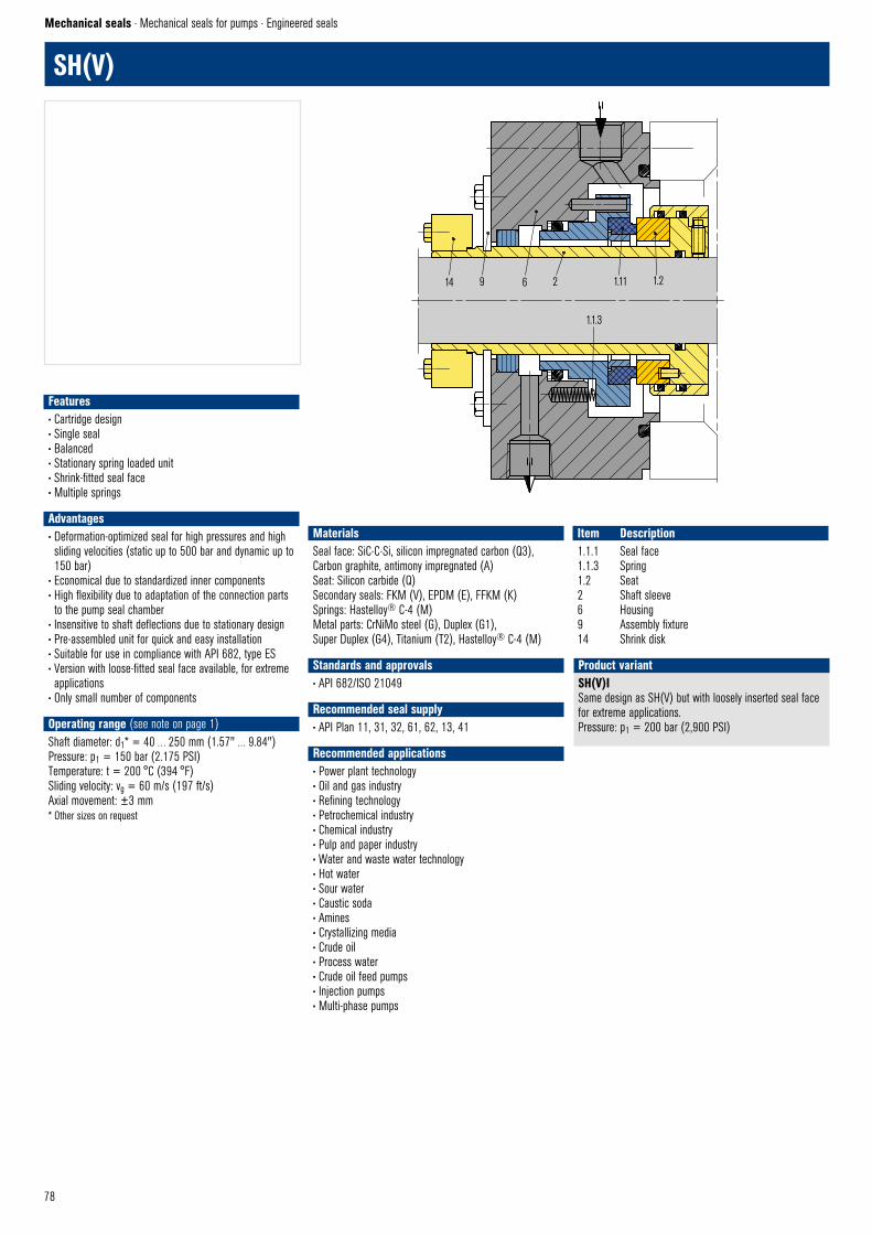
78
14 9 6 2 1.11 1.2
1.1.3
SHV © EagleBurgmann
SH(V)
Mechanical seals · Mechanical seals for pumps · Engineered seals
SH(V)ISame design as SH(V) but with loosely inserted seal face for extreme applications. Pressure: p1 = 200 bar (2,900 PSI)
Product variant
Features• Cartridge design • Single seal• Balanced• Stationary spring loaded unit• Shrink-fitted seal face• Multiple springs
Advantages• Deformation-optimized seal for high pressures and high sliding velocities (static up to 500 bar and dynamic up to 150 bar)
• Economical due to standardized inner components• High flexibility due to adaptation of the connection parts to the pump seal chamber
• Insensitive to shaft deflections due to stationary design• Pre-assembled unit for quick and easy installation• Suitable for use in compliance with API 682, type ES• Version with loose-fitted seal face available, for extreme applications
• Only small number of components
Operating range (see note on page 1)Shaft diameter: d1* = 40 … 250 mm (1.57" … 9.84")Pressure: p1 = 150 bar (2.175 PSI)Temperature: t = 200 °C (394 °F)Sliding velocity: vg = 60 m/s (197 ft/s)Axial movement: ±3 mm* Other sizes on request
Materials Seal face: SiC-C-Si, silicon impregnated carbon (Q3), Carbon graphite, antimony impregnated (A)Seat: Silicon carbide (Q)Secondary seals: FKM (V), EPDM (E), FFKM (K)Springs: Hastelloy® C-4 (M)Metal parts: CrNiMo steel (G), Duplex (G1),Super Duplex (G4), Titanium (T2), Hastelloy® C-4 (M)
Standards and approvals• API 682/ISO 21049
Recommended seal supply• API Plan 11, 31, 32, 61, 62, 13, 41
Recommended applications• Power plant technology• Oil and gas industry• Refining technology• Petrochemical industry• Chemical industry• Pulp and paper industry• Water and waste water technology• Hot water• Sour water• Caustic soda• Amines• Crystallizing media• Crude oil• Process water• Crude oil feed pumps• Injection pumps• Multi-phase pumps
Item Description1.1.1 Seal face1.1.3 Spring1.2 Seat2 Shaft sleeve6 Housing9 Assembly fixture14 Shrink disk

79
SHF/SHP
Mechanical seals · Mechanical seals for pumps · Engineered seals
SHF4Single mechanical seal with integrated jacket cooling,for boiler feed pumps.
Product variant
Features• Cartridge design • Single seal• Balanced• Dependent of direction of rotation• Integrated pumping device• Stationary spring loaded unit• Shrink-fitted seal face• Multiple springs
Advantages• Deformation-optimized seal for high sliding velocities and medium pressures
• Economical due to standardized inner components• Universal application for OEM or retrofits of boiler feed water pumps with floating ring seals, labyrinths or packings
• High flexibility due to adaptation of the connection parts to the pump seal chamber
• Optimum heat dissipation due to integrated pumping device and optimized seat design
• Insensitive to shaft deflections due to stationary design• Pre-assembled unit for quick and easy installation• Only small number of components• Short built
Operating range (see note on page 1)Shaft diameter: d1* = 40 … 250 mm (1.57" … 9.84")Pressure: p1 = 50 bar (725 PSI)Temperature: t = 300 °C (572 °F)Sliding velocity: vg = 60 m/s (197 ft/s)Axial movement: ±3 mm* Other sizes on request
Materials Seal face: Silicon carbide (Q), Carbon graphite antimony impregnated (A), Carbon graphite resin impregnated (B)Seat: Silicon carbide (Q)Secondary seals: EPDM (E), FFKM (K)Springs: CrNiMo steel (G)Metal parts: CrNiMo steel (G)
Recommended seal supply• API Plan 23
Recommended applications• Power plant technology• Oil and gas industry• Refining technology• Petrochemical industry• Chemical industry• Boiler feed water pumps
Item Description1.1.1 Seal face1.1.3 Spring1.2 Seat2 Shaft sleeve6 Cover8 Pumping screw with flow guide9 Assembly fixture14 Shrink disk
14 9 1.1.1 1.2
6 1.1.3 8 2
SHF © EagleBurgmann
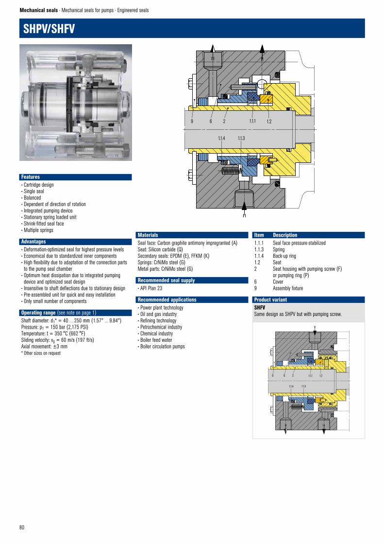
80
SHPV/SHFV
SHFVSame design as SHPV but with pumping screw.
Product variant
9 6 2 1.1.1 1.2
1.1.4 1.1.3
SHPV © EagleBurgmann
9 6 2 1.1.1 1.2
1.1.4 1.1.3
SHFV © EagleBurgmann
Features• Cartridge design • Single seal• Balanced• Dependent of direction of rotation• Integrated pumping device• Stationary spring loaded unit• Shrink-fitted seal face• Multiple springs
Advantages• Deformation-optimized seal for highest pressure levels• Economical due to standardized inner components• High flexibility due to adaptation of the connection parts to the pump seal chamber
• Optimum heat dissipation due to integrated pumping device and optimized seat design
• Insensitive to shaft deflections due to stationary design• Pre-assembled unit for quick and easy installation• Only small number of components
Operating range (see note on page 1)Shaft diameter: d1* = 40 … 250 mm (1.57" … 9.84")Pressure: p1 = 150 bar (2,175 PSI)Temperature: t = 350 °C (662 °F)Sliding velocity: vg = 60 m/s (197 ft/s)Axial movement: ±3 mm* Other sizes on request
MaterialsSeal face: Carbon graphite antimony impregranted (A)Seat: Silicon carbide (Q)Secondary seals: EPDM (E), FFKM (K)Springs: CrNiMo steel (G)Metal parts: CrNiMo steel (G)
Recommended seal supply• API Plan 23
Recommended applications• Power plant technology• Oil and gas industry• Refining technology• Petrochemical industry• Chemical industry• Boiler feed water• Boiler circulation pumps
Item Description1.1.1 Seal face pressure-stabilized1.1.3 Spring1.1.4 Back-up ring1.2 Seat2 Seat housing with pumping screw (F) or pumping ring (P)6 Cover9 Assembly fixture
Mechanical seals · Mechanical seals for pumps · Engineered seals

81
6 1 5 2 9
103478
SAFV1 © EagleBurgmann
SAF(V) / SAP(V)
Features• Cartridge design • Single seal• Balanced• Dependent on direction of rotation• Integrated pumping device• Stationary spring loaded unit• Inserted seal face• Rotating carbon seat
Advantages• Deformation-optimized seal for high sliding velocities and medium pressures
• Economical due to standardized inner components• High flexibility due to adaptation of the connection parts to the pump seal chamber
• Optimum heat dissipation due to integrated pumping device and optimized seat/seal face design
• Insensitive to shaft deflections due to stationary design• Pre-assembled unit for quick and easy installation• Only small number of components
Operating range (see note on page 1)Shaft diameter: d1* = 120 … 250 mm (4.72" … 9.84")Pressure: p1 = 50 bar (725 PSI)Temperature: t = 300 °C (572 °F)Sliding velocity: vg = 65 m/s (213 ft/s)Axial movement: ±3 mm* Other sizes on request
Materials Seal face: Silicon carbide (Q), SiC-C-Si, silicon impregnated carbon (Q3) Seat: Carbon graphite resin impregnated (B), SiC-C-Si, silicon impregnated carbon (Q3)Secondary seals: EPDM (E), FFKM (K)Springs: CrNiMo steel (G)Metal parts: CrNiMo steel (G)
Recommended seal supply• API Plan 02 + 23 (with jacket cooling)
Recommended applications• Power plant technology• Oil and gas industry• Refining technology• Petrochemical industry• Chemical industry• Boiler feed water with low conductivity• Boiler feed pumps
Item Description1 Seal face2, 4 O-Ring3 Spring5 Seat collar6 Seat7 Shaft sleeve8 Pumping sleeve9 Cover10 Throttle ring
Mechanical seals · Mechanical seals for pumps · Engineered seals
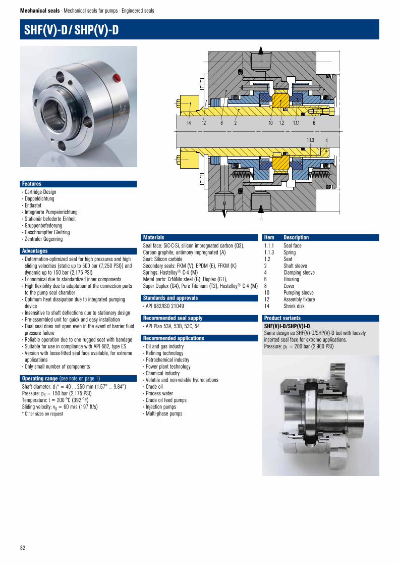
82
SHF(V)-D / SHP(V)-D
Mechanical seals · Mechanical seals for pumps · Engineered seals
SHF(V)I-D/SHP(V)I-DSame design as SHF(V)-D/SHP(V)-D but with loosely inserted seal face for extreme applications. Pressure: p1 = 200 bar (2,900 PSI)
Product variants
Features• Cartridge-Design • Doppeldichtung • Entlastet • Integrierte Pumpeinrichtung • Stationär befederte Einheit • Gruppenbefederung • Geschrumpfter Gleitring • Zentraler Gegenring
Advantages• Deformation-optimized seal for high pressures and high sliding velocities (static up to 500 bar (7,250 PSI)) and dynamic up to 150 bar (2,175 PSI)
• Economical due to standardized inner components• High flexibility due to adaptation of the connection parts to the pump seal chamber
• Optimum heat dissipation due to integrated pumping device
• Insensitive to shaft deflections due to stationary design• Pre-assembled unit for quick and easy installation• Dual seal does not open even in the event of barrier fluid pressure failure
• Reliable operation due to one rugged seat with bandage• Suitable for use in compliance with API 682, type ES• Version with loose-fitted seal face available, for extreme applications
• Only small number of components
Operating range (see note on page 1)Shaft diameter: d1* = 40 … 250 mm (1.57" … 9.84")Pressure: p3 = 150 bar (2,175 PSI)Temperature: t = 200 °C (392 °F)Sliding velocity: vg = 60 m/s (197 ft/s)* Other sizes on request
Materials Seal face: SiC-C-Si, silicon impregnated carbon (Q3), Carbon graphite, antimony impregnated (A) Seat: Silicon carbide Secondary seals: FKM (V), EPDM (E), FFKM (K)Springs: Hastelloy® C-4 (M)Metal parts: CrNiMo steel (G), Duplex (G1),Super Duplex (G4), Pure Titanium (T2), Hastelloy® C-4 (M)
Standards and approvals• API 682/ISO 21049
Recommended seal supply• API Plan 53A, 53B, 53C, 54
Recommended applications• Oil and gas industry • Refining technology• Petrochemical industry• Power plant technology• Chemical industry• Volatile and non-volatile hydrocarbons• Crude oil• Process water• Crude oil feed pumps• Injection pumps• Multi-phase pumps
Item Description1.1.1 Seal face1.1.3 Spring1.2 Seat2 Shaft sleeve4 Clamping sleeve6 Housing8 Cover10 Pumping sleeve12 Assembly fixture14 Shrink disk
14 12 8 2 10 1.2 1.1.1 6
1.1.3 4
SHFV–D © EagleBurgmann

83
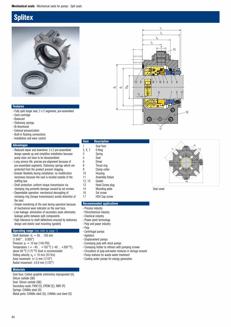
84
Splitex
Mechanical seals · Mechanical seals for pumps · Split seals
Seal cover
Features• Fully split single seal, 2 x 2 segments, pre-assembled• Semi-cartridge• Balanced• Stationary springs• Bi-directional• External pressurization• Built-in flushing connections• Installation and wear control
Advantages• Reduced repair and downtime: 2 x 2 pre-assembled design speeds up and simplifies installation because pump does not have to be disassembled.
• Long service life: precise pre-alignment because of pre-assembled segments. Stationary springs which are protected from the product prevent clogging.
• Greater flexibility during installation: no modification necessary because the seal is located outside of the stuffing box.
• Shaft protection: uniform torque transmission via clamping ring prevents damage caused by set screws.
• Dependable operation: mechanical decoupling of clamping ring (torque transmission) avoids distortion of the seat.
• Simple monitoring of the seal during operation because of mechanical wear indicator on the seal face.
• Low leakage: elimination of secondary seals eliminates leakage paths between split components.
• High tolerance to shaft deflections ensured by stationary design and elastic seat mounting (gasket).
Operating range (see note on page 1)Shaft diameter: d1 = 50 … 150 mm (1.940" … 6.000")Pressure: p1 = 10 bar (145 PSI)Temperature: t = – 40 … +150 °C (– 40 … +300 °F),above 80 °C (175 °F) flush is recommendedSliding velocity: vg = 10 m/s (33 ft/s)Axial movement: ±1.5 mm (1/16")Radial movement: ±0.8 mm (1/32")
Materials Seal face: Carbon graphite antimoniny impregnated (A), Silicon carbide (Q6)Seat: Silicon carbide (Q6)Secondary seals: FKM (V), EPDM (E), NBR (P)Springs: CrNiMo steel (G)Metal parts: CrNiMo steel (G), CrNiMo cast steel (G)
Recommended applications• Process industry• Petrochemical industry• Chemical industry• Power plant technology• Pulp and paper industry• Pulp• Centrifugal pumps• Agitators• Displacement pumps• Conveying pulp with stock pumps• Conveying timber to refiners with pumping screws• Circulation of pulp-and-water mixtures in storage vessels• Pump stations for waste water treatment• Cooling water pumps for energy generation
Item Description1 Seal face2, 5, 7 O-Ring3 Spring4 Seat6 Driver8 Thrust ring9 Clamp collar10 Housing11 Assembly fixture12, 15 Gasket13 Head Screw plug 14 Mounting plate16 Set screw17 HSH Cap screw
12 9 16 7 15 5 4 2 8
6 1 3 11
10
17
SPLITEX © EagleBurgmann
d 2 d 1 D W
l5
l1l2
l4l3
13
a14
s
Da
SPLITEX–Guss–Seite © EagleBurgmann
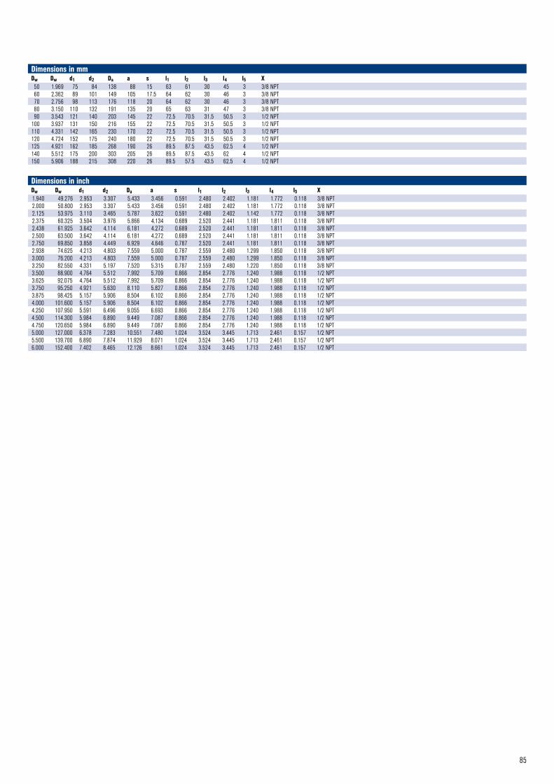
85
Dimensions in mmDw Dw d1 d2 Da a s l1 l2 l3 l4 l5 X50 1.969 75 84 138 88 15 63 61 30 45 3 3/8 NPT60 2.362 89 101 149 105 17.5 64 62 30 46 3 3/8 NPT70 2.756 98 113 176 118 20 64 62 30 46 3 3/8 NPT80 3.150 110 132 191 135 20 65 63 31 47 3 3/8 NPT90 3.543 121 140 203 145 22 72.5 70.5 31.5 50.5 3 1/2 NPT
100 3.937 131 150 216 155 22 72.5 70.5 31.5 50.5 3 1/2 NPT110 4.331 142 165 230 170 22 72.5 70.5 31.5 50.5 3 1/2 NPT120 4.724 152 175 240 180 22 72.5 70.5 31.5 50.5 3 1/2 NPT125 4.921 162 185 268 190 26 89.5 87.5 43.5 62.5 4 1/2 NPT140 5.512 175 200 303 205 26 89.5 87.5 43.5 62 4 1/2 NPT150 5.906 188 215 308 220 26 89.5 57.5 43.5 62.5 4 1/2 NPT
Dimensions in inchDw Dw d1 d2 Da a s l1 l2 l3 l4 l5 X1.940 49.276 2.953 3.307 5.433 3.456 0.591 2.480 2.402 1.181 1.772 0.118 3/8 NPT2.000 50.800 2.953 3.307 5.433 3.456 0.591 2.480 2.402 1.181 1.772 0.118 3/8 NPT2.125 53.975 3.110 3.465 5.787 3.622 0.591 2.480 2.402 1.142 1.772 0.118 3/8 NPT2.375 60.325 3.504 3.976 5.866 4.134 0.689 2.520 2.441 1.181 1.811 0.118 3/8 NPT2.438 61.925 3.642 4.114 6.181 4.272 0.689 2.520 2.441 1.181 1.811 0.118 3/8 NPT2.500 63.500 3.642 4.114 6.181 4.272 0.689 2.520 2.441 1.181 1.811 0.118 3/8 NPT2.750 69.850 3.858 4.449 6.929 4.646 0.787 2.520 2.441 1.181 1.811 0.118 3/8 NPT2.938 74.625 4.213 4.803 7.559 5.000 0.787 2.559 2.480 1.299 1.850 0.118 3/8 NPT3.000 76.200 4.213 4.803 7.559 5.000 0.787 2.559 2.480 1.299 1.850 0.118 3/8 NPT3.250 82.550 4.331 5.197 7.520 5.315 0.787 2.559 2.480 1.220 1.850 0.118 3/8 NPT3.500 88.900 4.764 5.512 7.992 5.709 0.866 2.854 2.776 1.240 1.988 0.118 1/2 NPT3.625 92.075 4.764 5.512 7.992 5.709 0.866 2.854 2.776 1.240 1.988 0.118 1/2 NPT3.750 95.250 4.921 5.630 8.110 5.827 0.866 2.854 2.776 1.240 1.988 0.118 1/2 NPT3.875 98.425 5.157 5.906 8.504 6.102 0.866 2.854 2.776 1.240 1.988 0.118 1/2 NPT4.000 101.600 5.157 5.906 8.504 6.102 0.866 2.854 2.776 1.240 1.988 0.118 1/2 NPT4.250 107.950 5.591 6.496 9.055 6.693 0.866 2.854 2.776 1.240 1.988 0.118 1/2 NPT4.500 114.300 5.984 6.890 9.449 7.087 0.866 2.854 2.776 1.240 1.988 0.118 1/2 NPT4.750 120.650 5.984 6.890 9.449 7.087 0.866 2.854 2.776 1.240 1.988 0.118 1/2 NPT5.000 127.000 6.378 7.283 10.551 7.480 1.024 3.524 3.445 1.713 2.461 0.157 1/2 NPT5.500 139.700 6.890 7.874 11.929 8.071 1.024 3.524 3.445 1.713 2.461 0.157 1/2 NPT6.000 152.400 7.402 8.465 12.126 8.661 1.024 3.524 3.445 1.713 2.461 0.157 1/2 NPT
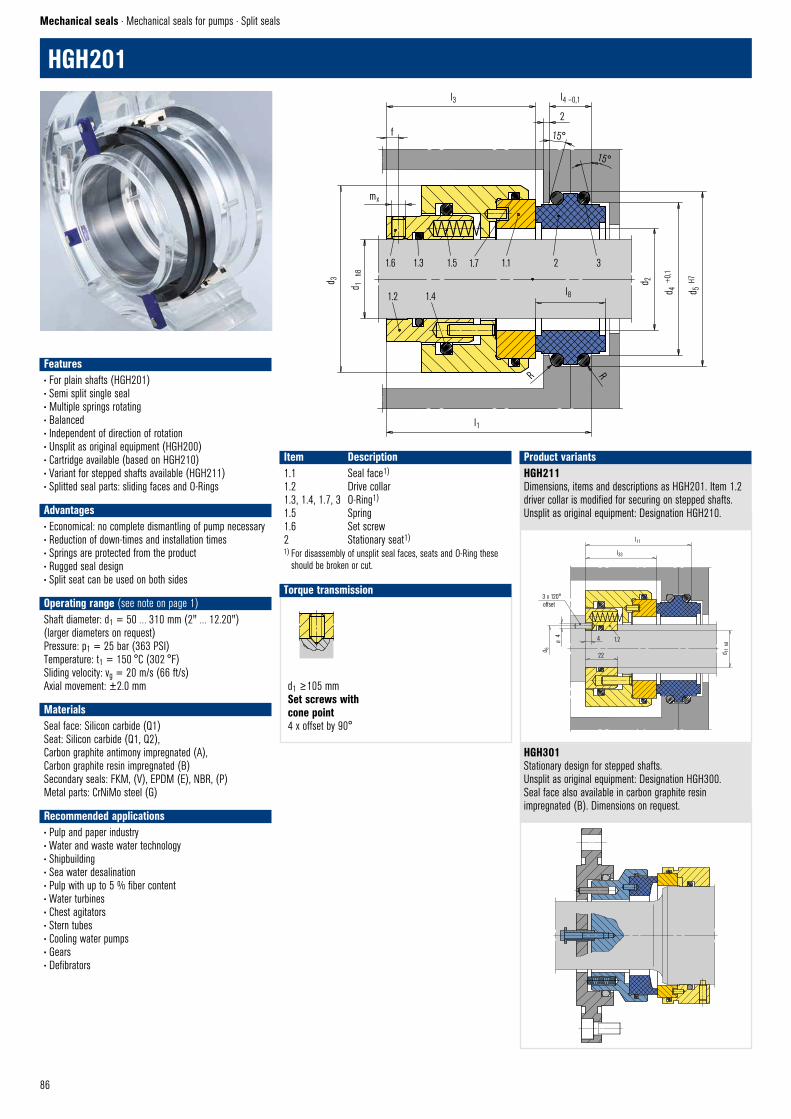
86
d1 ≥105 mm Set screws withcone point4 x offset by 90°
Set screw with cone point © EagleBurgmann
HGH201
Mechanical seals · Mechanical seals for pumps · Split seals
Item Description1.1 Seal face1)
1.2 Drive collar1.3, 1.4, 1.7, 3 O-Ring1)
1.5 Spring1.6 Set screw2 Stationary seat1)1) For disassembly of unsplit seal faces, seats and O-Ring these
should be broken or cut.
HGH211Dimensions, items and descriptions as HGH201. Item 1.2 driver collar is modified for securing on stepped shafts.Unsplit as original equipment: Designation HGH210.
HGH301Stationary design for stepped shafts.Unsplit as original equipment: Designation HGH300.Seal face also available in carbon graphite resin impregnated (B). Dimensions on request.
Product variants
Torque transmission
Features• For plain shafts (HGH201) • Semi split single seal• Multiple springs rotating• Balanced• Independent of direction of rotation• Unsplit as original equipment (HGH200)• Cartridge available (based on HGH210)• Variant for stepped shafts available (HGH211)• Splitted seal parts: sliding faces and O-Rings
Advantages• Economical: no complete dismantling of pump necessary• Reduction of down-times and installation times• Springs are protected from the product• Rugged seal design• Split seat can be used on both sides
Operating range (see note on page 1)Shaft diameter: d1 = 50 … 310 mm (2" … 12.20")(larger diameters on request)Pressure: p1 = 25 bar (363 PSI)Temperature: t1 = 150 °C (302 °F)Sliding velocity: vg = 20 m/s (66 ft/s)Axial movement: ±2.0 mm
MaterialsSeal face: Silicon carbide (Q1) Seat: Silicon carbide (Q1, Q2),Carbon graphite antimony impregnated (A),Carbon graphite resin impregnated (B) Secondary seals: FKM, (V), EPDM (E), NBR, (P)Metal parts: CrNiMo steel (G)
Recommended applications• Pulp and paper industry• Water and waste water technology• Shipbuilding• Sea water desalination• Pulp with up to 5 % fiber content• Water turbines• Chest agitators• Stern tubes• Cooling water pumps• Gears• Defibrators
l3
f
l4 –0,1
2
15°
15°
mx
d 3 d 1
h8
1.6 1.3 1.5 1.1
1.2 1.4
2 3
l8
d 2
d 4 +
0,1
d 5 H7
l1
HGH © EagleBurgmann
R R
1.7
4 1.2
22
3 x 120°
d 6
Ø 4
l11
l33
d 11
h8
HGH211 © EagleBurgmann
offset
HGH300 © EagleBurgmann
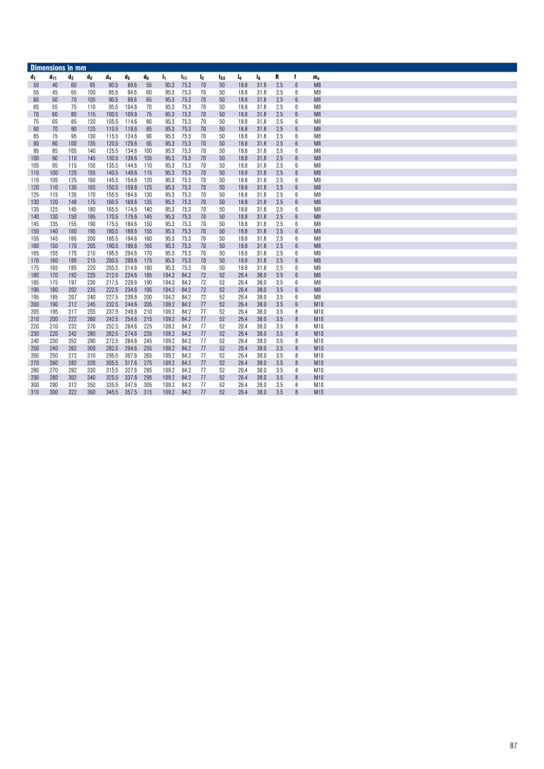
87
Dimensions in mmd1 d11 d2 d3 d4 d5 d6 l1 l11 l3 l33 l4 l8 R f mx50 40 60 95 80.5 89.6 55 95.3 75.3 70 50 18.8 31.8 2.5 6 M855 45 65 100 85.5 94.6 60 95.3 75.3 70 50 18.8 31.8 2.5 6 M860 50 70 105 90.5 99.6 65 95.3 75.3 70 50 18.8 31.8 2.5 6 M865 55 75 110 95.5 104.6 70 95.3 75.3 70 50 18.8 31.8 2.5 6 M870 60 80 115 100.5 109.6 75 95.3 75.3 70 50 18.8 31.8 2.5 6 M875 65 85 120 105.5 114.6 80 95.3 75.3 70 50 18.8 31.8 2.5 6 M880 70 90 125 110.5 119.6 85 95.3 75.3 70 50 18.8 31.8 2.5 6 M885 75 95 130 115.5 124.6 90 95.3 75.3 70 50 18.8 31.8 2.5 6 M890 80 100 135 120.5 129.6 95 95.3 75.3 70 50 18.8 31.8 2.5 6 M895 85 105 140 125.5 134.6 100 95.3 75.3 70 50 18.8 31.8 2.5 6 M8
100 90 110 145 130.5 139.6 105 95.3 75.3 70 50 18.8 31.8 2.5 6 M8105 95 115 150 135.5 144.6 110 95.3 75.3 70 50 18.8 31.8 2.5 6 M8110 100 120 155 140.5 149.6 115 95.3 75.3 70 50 18.8 31.8 2.5 6 M8115 105 125 160 145.5 154.6 120 95.3 75.3 70 50 18.8 31.8 2.5 6 M8120 110 130 165 150.5 159.6 125 95.3 75.3 70 50 18.8 31.8 2.5 6 M8125 115 135 170 155.5 164.6 130 95.3 75.3 70 50 18.8 31.8 2.5 6 M8130 120 140 175 160.5 169.6 135 95.3 75.3 70 50 18.8 31.8 2.5 6 M8135 125 145 180 165.5 174.6 140 95.3 75.3 70 50 18.8 31.8 2.5 6 M8140 130 150 185 170.5 179.6 145 95.3 75.3 70 50 18.8 31.8 2.5 6 M8145 135 155 190 175.5 184.6 150 95.3 75.3 70 50 18.8 31.8 2.5 6 M8150 140 160 195 180.5 189.6 155 95.3 75.3 70 50 18.8 31.8 2.5 6 M8155 145 165 200 185.5 194.6 160 95.3 75.3 70 50 18.8 31.8 2.5 6 M8160 150 170 205 190.5 199.6 165 95.3 75.3 70 50 18.8 31.8 2.5 6 M8165 155 175 210 195.5 204.6 170 95.3 75.3 70 50 18.8 31.8 2.5 6 M8170 160 180 215 200.5 209.6 175 95.3 75.3 70 50 18.8 31.8 2.5 6 M8175 165 185 220 205.5 214.6 180 95.3 75.3 70 50 18.8 31.8 2.5 6 M8180 170 192 225 212.5 224.6 185 104.2 84.2 72 52 26.4 38.0 3.5 6 M8185 175 197 230 217.5 229.6 190 104.2 84.2 72 52 26.4 38.0 3.5 6 M8190 180 202 235 222.5 234.6 195 104.2 84.2 72 52 26.4 38.0 3.5 6 M8195 185 207 240 227.5 239.6 200 104.2 84.2 72 52 26.4 38.0 3.5 6 M8200 190 212 245 232.5 244.6 205 109.2 84.2 77 52 26.4 38.0 3.5 6 M10205 195 217 255 237.5 249.6 210 109.2 84.2 77 52 26.4 38.0 3.5 8 M10210 200 222 260 242.5 254.6 215 109.2 84.2 77 52 26.4 38.0 3.5 8 M10220 210 232 270 252.5 264.6 225 109.2 84.2 77 52 26.4 38.0 3.5 8 M10230 220 242 280 262.5 274.6 235 109.2 84.2 77 52 26.4 38.0 3.5 8 M10240 230 252 290 272.5 284.6 245 109.2 84.2 77 52 26.4 38.0 3.5 8 M10250 240 262 300 282.5 294.6 255 109.2 84.2 77 52 26.4 38.0 3.5 8 M10260 250 272 310 295.5 307.6 265 109.2 84.2 77 52 26.4 38.0 3.5 8 M10270 260 282 320 305.5 317.6 275 109.2 84.2 77 52 26.4 38.0 3.5 8 M10280 270 292 330 315.5 327.6 285 109.2 84.2 77 52 26.4 38.0 3.5 8 M10290 280 302 340 325.5 337.6 295 109.2 84.2 77 52 26.4 38.0 3.5 8 M10300 290 312 350 335.5 347.6 305 109.2 84.2 77 52 26.4 38.0 3.5 8 M10310 300 322 360 345.5 357.5 315 109.2 84.2 77 52 26.4 38.0 3.5 8 M10
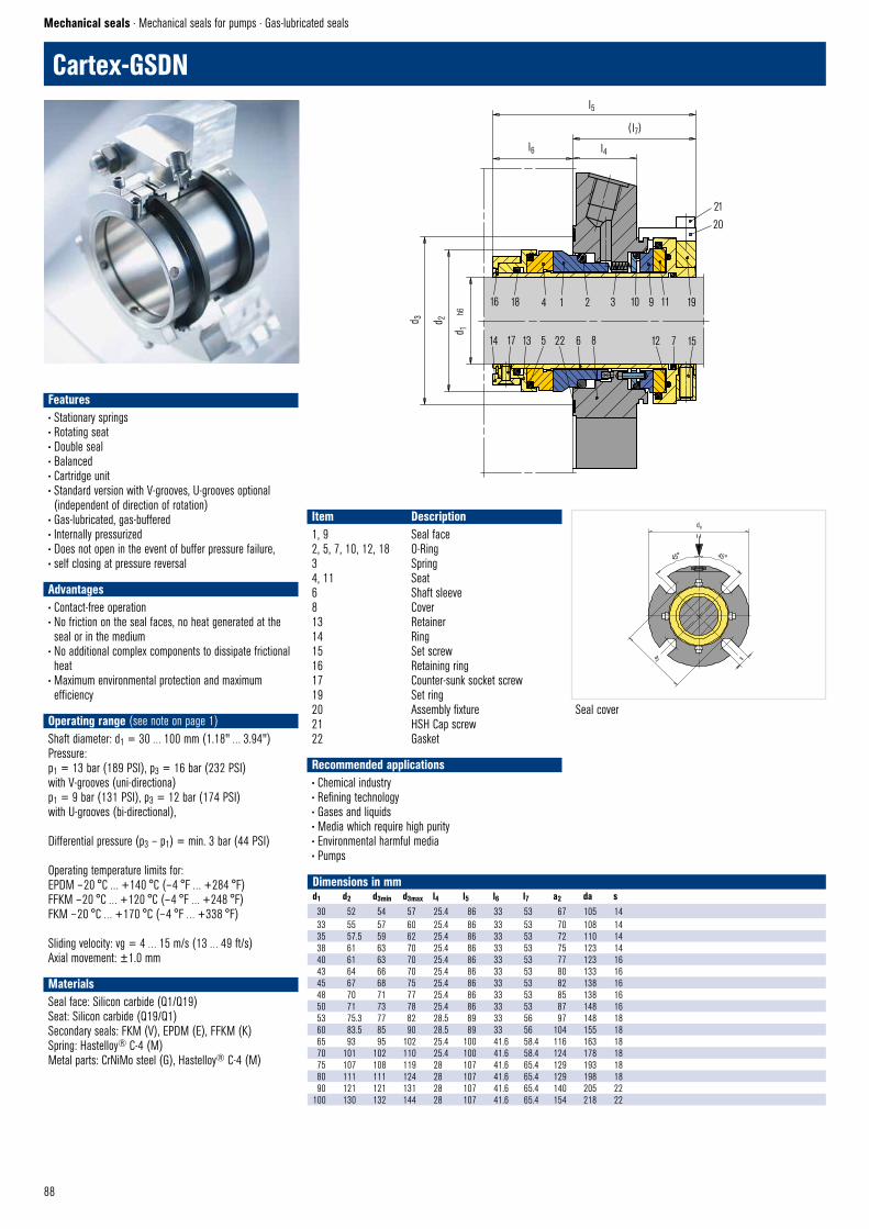
88
Cartex-GSDN
Mechanical seals · Mechanical seals for pumps · Gas-lubricated seals
Seal cover
Dimensions in mmd1 d2 d3min d3max l4 l5 l6 l7 a2 da s30 52 54 57 25.4 86 33 53 67 105 1433 55 57 60 25.4 86 33 53 70 108 1435 57.5 59 62 25.4 86 33 53 72 110 1438 61 63 70 25.4 86 33 53 75 123 1440 61 63 70 25.4 86 33 53 77 123 1643 64 66 70 25.4 86 33 53 80 133 1645 67 68 75 25.4 86 33 53 82 138 1648 70 71 77 25.4 86 33 53 85 138 1650 71 73 78 25.4 86 33 53 87 148 1653 75.3 77 82 28.5 89 33 56 97 148 1860 83.5 85 90 28.5 89 33 56 104 155 1865 93 95 102 25.4 100 41.6 58.4 116 163 1870 101 102 110 25.4 100 41.6 58.4 124 178 1875 107 108 119 28 107 41.6 65.4 129 193 1880 111 111 124 28 107 41.6 65.4 129 198 1890 121 121 131 28 107 41.6 65.4 140 205 22
100 130 132 144 28 107 41.6 65.4 154 218 22
Item Description1, 9 Seal face2, 5, 7, 10, 12, 18 O-Ring3 Spring4, 11 Seat6 Shaft sleeve8 Cover13 Retainer14 Ring15 Set screw16 Retaining ring17 Counter-sunk socket screw19 Set ring20 Assembly fixture21 HSH Cap screw22 Gasket
Recommended applications• Chemical industry• Refining technology• Gases and liquids• Media which require high purity• Environmental harmful media• Pumps
Features• Stationary springs • Rotating seat• Double seal• Balanced• Cartridge unit• Standard version with V-grooves, U-grooves optional (independent of direction of rotation)
• Gas-lubricated, gas-buffered• Internally pressurized• Does not open in the event of buffer pressure failure, • self closing at pressure reversal• Advantages• Contact-free operation• No friction on the seal faces, no heat generated at the seal or in the medium
• No additional complex components to dissipate frictional heat
• Maximum environmental protection and maximum efficiency
• Operating range (see note on page 1)Shaft diameter: d1 = 30 … 100 mm (1.18" … 3.94")Pressure: p1 = 13 bar (189 PSI), p3 = 16 bar (232 PSI) with V-grooves (uni-directiona)p1 = 9 bar (131 PSI), p3 = 12 bar (174 PSI) with U-grooves (bi-directional),
Differential pressure (p3 – p1) = min. 3 bar (44 PSI)
Operating temperature limits for:EPDM – 20 °C … +140 °C (– 4 °F … +284 °F)FFKM – 20 °C … +120 °C (– 4 °F … +248 °F)FKM – 20 °C … +170 °C (– 4 °F … +338 °F)
Sliding velocity: vg = 4 … 15 m/s (13 … 49 ft/s)Axial movement: ±1.0 mm
MaterialsSeal face: Silicon carbide (Q1/Q19)Seat: Silicon carbide (Q19/Q1) Secondary seals: FKM (V), EPDM (E), FFKM (K) Spring: Hastelloy® C-4 (M)Metal parts: CrNiMo steel (G), Hastelloy® C-4 (M)
16 18 4 1 2 3 10 9 11 19
14 17 13 5 22 6 8 12 7 15
21
20
l5
l6 l4
( l7)
d 3 d 2
d 1
h6
CARTEX – GSDN © EagleBurgmann
CARTEX – GSDN © EagleBurgmann
45°45°
da
a2 s
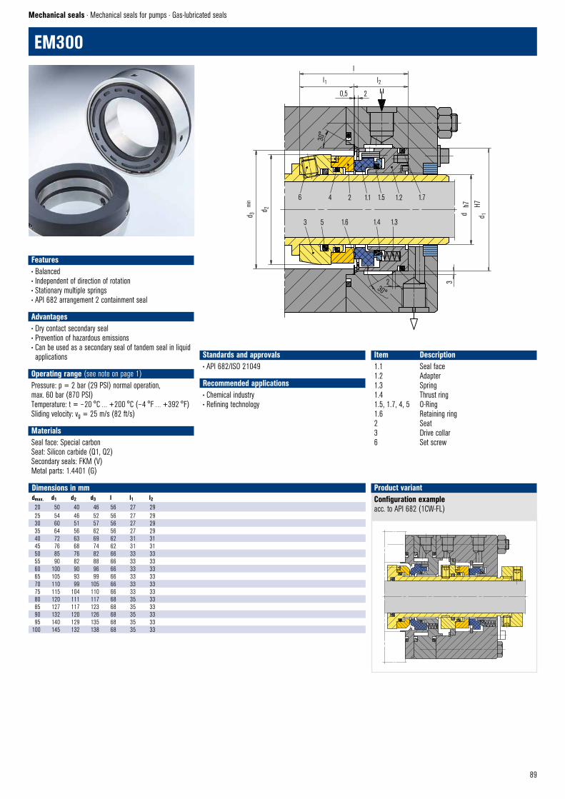
89
Standards and approvals• API 682/ISO 21049
Recommended applications• Chemical industry• Refining technology
6 4 2 1.1 1.5 1.2 1.7
3 5 1.6 1.4 1.3
d 3m
in
d 2
ll1 l2
0,5 2
30°
d d 1
h7 H7
3230°
EM300 © EagleBurgmann
Configuration exampleacc. to API 682 (1CW-FL)
Product variant
EM300–45 Cartridge © EagleBurgmann
EM300
Mechanical seals · Mechanical seals for pumps · Gas-lubricated seals
Item Description1.1 Seal face1.2 Adapter1.3 Spring1.4 Thrust ring1.5, 1.7, 4, 5 O-Ring1.6 Retaining ring2 Seat3 Drive collar6 Set screw
Features• Balanced• Independent of direction of rotation• Stationary multiple springs• API 682 arrangement 2 containment seal• Advantages• Dry contact secondary seal• Prevention of hazardous emissions• Can be used as a secondary seal of tandem seal in liquid applications
• Operating range (see note on page 1)Pressure: p = 2 bar (29 PSI) normal operation, max. 60 bar (870 PSI)Temperature: t = – 20 °C … +200 °C (– 4 °F … +392 °F)Sliding velocity: vg = 25 m/s (82 ft/s)
MaterialsSeal face: Special carbonSeat: Silicon carbide (Q1, Q2)Secondary seals: FKM (V)Metal parts: 1.4401 (G)
Dimensions in mmdmax. d1 d2 d3 l l1 l220 50 40 46 56 27 2925 54 46 52 56 27 2930 60 51 57 56 27 2935 64 56 62 56 27 2940 72 63 69 62 31 3145 76 68 74 62 31 3150 85 76 82 66 33 3355 90 82 88 66 33 3360 100 90 96 66 33 3365 105 93 99 66 33 3370 110 99 105 66 33 3375 115 104 110 66 33 3380 120 111 117 68 35 3385 127 117 123 68 35 3390 132 120 126 68 35 3395 140 129 135 68 35 33
100 145 132 138 68 35 33

90
CGSH-K
Mechanical seals · Mechanical seals for pumps · Gas-lubricated seals
Item Part no. to DIN 24250 Description 1.1 472 Seal face1.2 412.1 O-Ring1.3 474 Thrust ring1.4 485 Drive collar1.5 477 Spring1.6 904 Set screw2 475.1 Seat3 412.3 O-Ring
1) d1 >105: 2 mm x 30°2) d1 >105: 30°3) d1 >105: + 0.14) d1 >105: H75) 3 x 120°
Recommended applications• Chemical industry• Refining technology• Gases and liquids (single seals only gas)• Gases and liquids which must not get into the atmosphere (dual seal)
• Gases not harmful to the enivronment (single seal)• Fans• Small steam turbines• Blowers• Roots compressors• Pumps
Features• For stepped shafts• Rotating spring• Single or double seal available• Balanced• Standard version with U-grooves, V-grooves optional (dependent of direction of rotation)
• Gas-lubricated• Does not open in the event of buffer pressure failure, • self closing at pressure reversal • Advantages• Contact-free operation, no friction• No differential pressure required with hard/soft material combination
• Applicable as containment seal acc. to API 682 • Operating range (see note on page 1)Shaft diameter: d1 = 28 … 125 mm (1.10" … 4.92")Pressure: p1 = 25 bar (363 PSI)Temperature: t* = – 20 °C … +170 °C (– 4 °F … +338 °F)Sliding velocity: vg = 4 … 25 m/s (13 … 82 ft/s)* Depending on resistance of O-Rings
Materials Seal face: Carbon graphite antimony impregnated (A), Silicon carbide (Q2),alternatively: Carbon graphite resin impregnated (B), Silicon carbide (Q1)Seat: Silicon carbide (Q1, Q2),Silicon carbide (Q19, Q29) with seal face in Q1 resp. Q2Metal parts: CrNiMo steel (G)
Standards and approvals• EN 12756• API 682/ISO 21049
1.4 1.5 1.3 1.1 2
1.6 5) 1.23 1)
R1,6 310° 2)
d 3 d 2h6
d 1 d 6 d 7
H11 3
)
H8 4
)
mx
f
CGSH – K © EagleBurgmann
l1K
l2
l6l5
l7 +0,5

91
Dimensions in mmd1 d2 d3 d6 d7 l1K l1' l2 l4' l5 l6 l7 f mx28* 33 53 37.0 43.0 50.0 89 20 44.5 2.0 5 9 5 M630* 35 55 39.0 45.0 50.0 89 20 44.5 2.0 5 9 5 M632* 38 60 42.0 48.0 50.0 89 20 44.5 2.0 5 9 5 M633* 38 60 42.0 48.0 50.0 89 20 44.5 2.0 5 9 5 M635* 40 62 44.0 50.0 50.0 89 20 44.5 2.0 5 9 5 M638* 43 65 49.0 56.0 52.5 95 23 47.5 2.0 6 9 5 M640* 45 67 51.0 58.0 52.5 95 23 47.5 2.0 6 9 5 M643* 48 70 54.0 61.0 52.5 95 23 47.5 2.0 6 9 5 M645* 50 72 56.0 63.0 52.5 95 23 47.5 2.0 6 9 5 M648* 53 75 59.0 66.0 52.5 95 23 47.5 2.0 6 9 5 M650* 55 77 62.0 70.0 57.5 104 25 52.0 2.5 6 9 5 M653* 58 84 65.0 73.0 57.5 104 25 52.0 2.5 6 9 5 M655* 60 86 67.0 75.0 57.5 106 25 53.0 2.5 6 9 5 M658* 63 89 70.0 78.0 62.5 112 25 56.0 2.5 6 9 7 M860* 65 91 72.0 80.0 62.5 112 25 56.0 2.5 6 9 7 M863* 68 94 75.0 83.0 62.5 112 25 56.0 2.5 6 9 7 M865* 70 97 77.0 85.0 62.5 112 25 56.0 2.5 6 9 7 M870* 75 104 83.0 92.0 70.0 126 28 63.0 2.5 7 9 7 M875* 80 109 88.0 97.0 70.0 126 28 63.0 2.5 7 9 7 M880* 85 114 95.0 105.0 70.0 126 28 63.0 3.0 7 9 7 M885* 90 119 100.0 110.0 75.0 126 28 63.0 3.0 7 9 7 M890* 95 124 105.0 115.0 75.0 126 28 63.0 3.0 7 9 7 M895* 100 129 110.0 120.0 75.0 126 28 63.0 3.0 7 9 7 M8
100* 105 132 115.0 125.0 75.0 126 28 63.0 3.0 7 9 7 M8105* 115 153 122.2 134.3 73.0 136 32 68.0 2.0 10 – 7 M8110* 120 158 128.2 140.3 73.0 136 32 68.0 2.0 10 – 7 M8115* 125 163 136.2 148.3 73.0 136 32 68.0 2.0 10 – 7 M8120* 130 168 138.2 150.3 73.0 136 32 68.0 2.0 10 – 7 M8125* 135 173 142.2 154.3 73.0 136 32 68.0 2.0 10 – 7 M8
* EN12756
CGSH-KDDouble seal back-to-back, buffered with gas, according to API 682 configuration 3NC-BB, Plan 74.Items, descriptions and unspecified dimensions as for CGSH-K. .
Pressure: p1 = … 22 bar (319 PSI), p3 = … 25 bar (363 PSI)(over the whole nominal diameter range, higher values on request).Differential pressure Δp = min. 3 bar (44 PSI)Other operating limits as CGSH-K.
Tandem arrangement acc. to API 682 3rd EditionConfiguration: 2CW-CS, Plan 72, 75, 76.For media with a gaseous leakage. H75VN on the productside. In case of a failure, the CGSH on the atmosphere side, works as a liquid seal.
Product variants
CGS-Tandem © EagleBurgmann
FCSV76
GBI72
CSD75
l1'
CGSH – KD © EagleBurgmann
l4'
GBI74
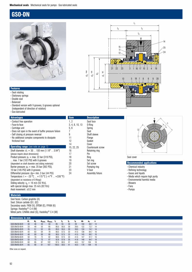
92
GSO-DN
Mechanical seals · Mechanical seals for pumps · Gas-lubricated seals
Item Description1, 2 Seal face3, 4, 8, 10, 13 O-Ring5, 6 Spring7 Seat9 Shaft sleeve11 Flange12 Gasket14 Cover15, 22, 25 Countersunk screw16 Retaining ring17 Pin18 Ring19 Set ring20 Set screw21 Pumping ring23 V-Seal24 Assembly fixture
Dimensions in mmd1 d2 d3min. d3max. l1 l2 l3 l4 da a2 s
GSO-DN/30-00-R 30 46 49 59 85 55 30 39 104 69.7 14GSO-DN/33-00-R 33 49 53 65 85.5 55.5 30 39.5 122 72.7 14GSO-DN/35-00-R 35 51 52 65 85.5 55.5 30 39.5 124 74.7 14GSO-DN/43-00-R 43 63 64 78 90.5 57.5 33 41.5 138 84.7 16GSO-DN/48-00-R 48 69 69 80 90.5 57.5 33 41.5 145 89.7 16GSO-DN/50-00-R 50 70 72 82 90.5 57.5 33 41.5 147 91.7 16GSO-DN/53-00-R 53 73 73 87 92.8 57.8 35 41.8 148 94.7 18GSO-DN/60-00-R 60 85 87 102 97.5 60.5 37 44.5 157 104 18GSO-DN/65-00-R 65 90 91 107 100.5 59.5 41 43.5 178 109 18
Other sizes on request.
Seal cover
Recommended applications• Chemical industry• Refining technology• Gases and liquids• Media which require high purity• Environmental harmful media• Blowers• Fans• Pumps
Features• Seat rotating• Stationary springs• Double seal • Balanced• Standard version with V-grooves, U-grooves optional (independent of direction of rotation)
• Gas-lubricated• Advantages• Contact free operation• Face-to-face• Cartridge unit• Does not open in the event of buffer pressure failure• Self closing at pressure reversal• No additional complex components to dissipate frictional heat
• Operating range (see note on page 1)Shaft diameter: d1 = 30 … 100 mm (1.18" … 3.94")(please inquire about dimensions)Product pressure: p1 = max. 22 bar (319 PSI), … max. 7 bar (102 PSI) with U-grooves(dependent on shaft diameter and sliding materials)Barrier pressure: p3 = max. 25 bar (362 PSI), 10 bar (145 PSI) with U-grooves Differential pressure: Δp= min. 3 bar (44 PSI)Temperature: t = – 20 °C … +170 °C (– 4 °F … +338 °F)(dependent on resistance of O-Rings)Sliding velocity: vg = 16 m/s (52 ft/s),with special design max. 25 m/s (82 ft/s)Axial movement: ±0.2 mm
MaterialsSeal faces: Carbon graphite (A)Seat: Silicon carbide (Q1, Q2) Secondary seals: FKM (V), EPDM (E), FFKM (K) Springs: Hastelloy® C-4 (M)Metal parts: CrNiMo steel (G), Hastelloy® C-4 (M)
14
25
24
1 16 17 10 2 4 1921 22 23 3
d 3
max
d 3
min
d 2
d 1
h6
151112
l1
l3
l4
l2
13 5 18 7 8 6 9 20
45°
45°
da
a2S
GSO–D © EagleBurgmann
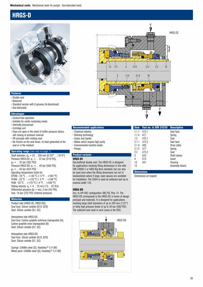
93
Mechanical seals · Mechanical seals for pumps · Gas-lubricated seals
HRGS-D
Features• Double seal • Balanced• Standard version with U-grooves (bi-directional)• Gas-lubricated• Advantages• Contact-free operation• Suitable for solids containing media• Internally pressurized• Cartridge unit• Does not open in the event of buffer pressure failure, self closing at pressure reversal
• HR principle with rotating seat• No friction on the seal faces, no heat generated at the seal or in the medium
• Operating range (see note on page 1)Shaft diameter: dw = 20 … 200 mm (0.787" … 7.874")Pressure HRGS-DC: p1 = … 22 bar (319 PSI),p3 = … 25 bar (362 PSI)Pressure HRGS-DD: p1 = … 40 bar (580 PSI)p3 = … 43 bar (624 PSI)Operating temperature limits for:EPDM – 20 °C … +140 °C (– 4 °F … +284 °F)FFKM – 20 °C … +120 °C (– 4 °F … +248 °F)FKM – 20 °C … +170 °C (– 4 °F … +338 °F)Sliding velocity: vg = 4 … 25 m/s (13 … 82 ft/s)Differential pressure Δp = min. 3 bar (44 PSI), max. 16 bar (232 PSI) (internal pressure)
MaterialsProduct side (HRGS-DC, HRGS-DD):Seal face: Silicon carbide (Q19, Q29)Seat: Silicon carbide (Q1, Q2)
Atmosphere side HRGS-DC:Seal face: Carbon graphite antimony impregnated (A), Carbon graphite resin impregnated (B)Seat: Silicon carbide (Q1, Q2)
Atmosphere side HRGS-DD:Seal face: Silicon carbide (Q19, Q29)Seat: Silicon carbide (Q1, Q2)
Springs: CrNiMo steel (G), Hastelloy® C-4 (M)Metal parts: CrNiMo steel (G), Hastelloy® C-4 (M)
Item Part no. to DIN 24250 Description1.1.1 472.1 Seal face1.1.4 477 Spring1.2 475.1 Seat2.1.1 472.2 Seal face2.1.4 485 Drive collar2.1.5 477 Spring2.2 475.2 Seat3 523 Shaft sleeve4 513 Insert10 441 Housing13 Assembly fixture
DimensionsDimensions on request
Recommended applications• Chemical industry• Refining technology• Gases and liquids• Media which require high purity• Environmental harmful media• Pumps
HRGS-DC Gas-buffered double seal. The HRGS-DC is designed for applications involving fitting dimensions in line with DIN 24960 C or ANSI Big Bore standard, but can also be used even when the fitting dimensions are not of standardized nature if large, open spaces are available for installation. The CGSH is used as outboard seal up to nominal width 125.
HRGS-DDAcc. to API 682 configuration 3NC-FB, Plan 74. The HRGS-DD corresponds to the HRGS-DC in terms of design principal and materials. It is designed for applications involving large shaft diameters of up to 200 mm (7.87") or fairly high pressure levels of up to 40 bar (580 PSI). The outboard seal used in such cases is the DGS.
Product variants
1.2 1.1.1 4 2.1.5 2.1.1 2.2 13
3 1.1.4 2.1.4 10
HRGS–D © EagleBurgmann
HRGS-DC
HRGS-DD
HRGS–DD © EagleBurgmann
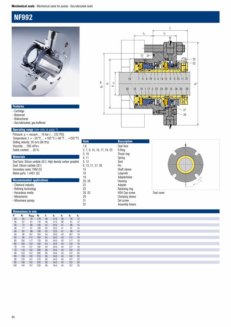
94
NF992
Mechanical seals · Mechanical seals for pumps · Gas-lubricated seals
Seal cover
Item Description1,8 Seal face2, 7, 9, 14, 16, 17, 24, 25 O-Ring3, 10 Thrust ring4, 11 Spring5, 12 Seat6, 13, 21, 27, 30 Pin15 Shaft sleeve18 Labyrinth19 Adapterhülse20, 26 Housing22 Adapter23 Retaining ring28, 33 HSH Cap screw29 Clamping sleeve31 Set screw32 Assembly fixture
Dimensions in mmd d1 d2min d3 l1 l2 l3 l4 l525 62 76 118 49 31.5 38 76 1230 67 81 118 49 31.5 38 81 1235 72 86 128 52 32.5 41 86 1440 77 91 138 52 32.5 41 91 1445 82 96 138 52 32.5 41 96 1450 90 107 164 54 34.5 43 107 1855 95 112 164 54 34.5 43 112 1860 100 117 178 54 34.5 43 117 1865 105 122 193 54 34.5 43 122 1870 110 127 193 54 34.5 43 127 1875 118 132 208 56 34.5 43 132 2080 123 137 208 56 34.5 43 137 2085 128 142 218 56 34.5 43 142 2090 133 147 218 56 34.5 43 147 2095 138 152 228 56 34.5 43 152 20
100 145 157 228 56 34.5 43 157 20
NF992 © EagleBurgmann
45°
l 5
l4
Features• Cartridge • Balanced• Bidirectional• Gas-lubricated, gas-buffered • Operating range (see note on page 1)Pressure: p = vacuum … 16 bar ( … 232 PSI)Temperature: t = – 20 °C … +160 °C (– 66 °F … +320 °F)Sliding velocity: 20 m/s (66 ft/s)Viscosity: … 300 mPa·sSolids content: … 20 %
Materials Seal face: Silicon carbide (Q1), High density carbon graphiteSeat: Silicon carbide (Q1)Secondary seals: FKM (V)Metal parts: 1.4401 (G)
Recommended applications• Chemical industry• Refining technology• Hazardous media • Monomeres• Monomere pumps
18 7 5 6 19 3 4 14 12 8 9 10 11 31
20 16 15 1 17 2 22 23 25 13 26 30 29
27
28
NF992 © EagleBurgmann
3332
21 24
l3 l2
l1
d 3
d 2
min
d 1
d h
7

95
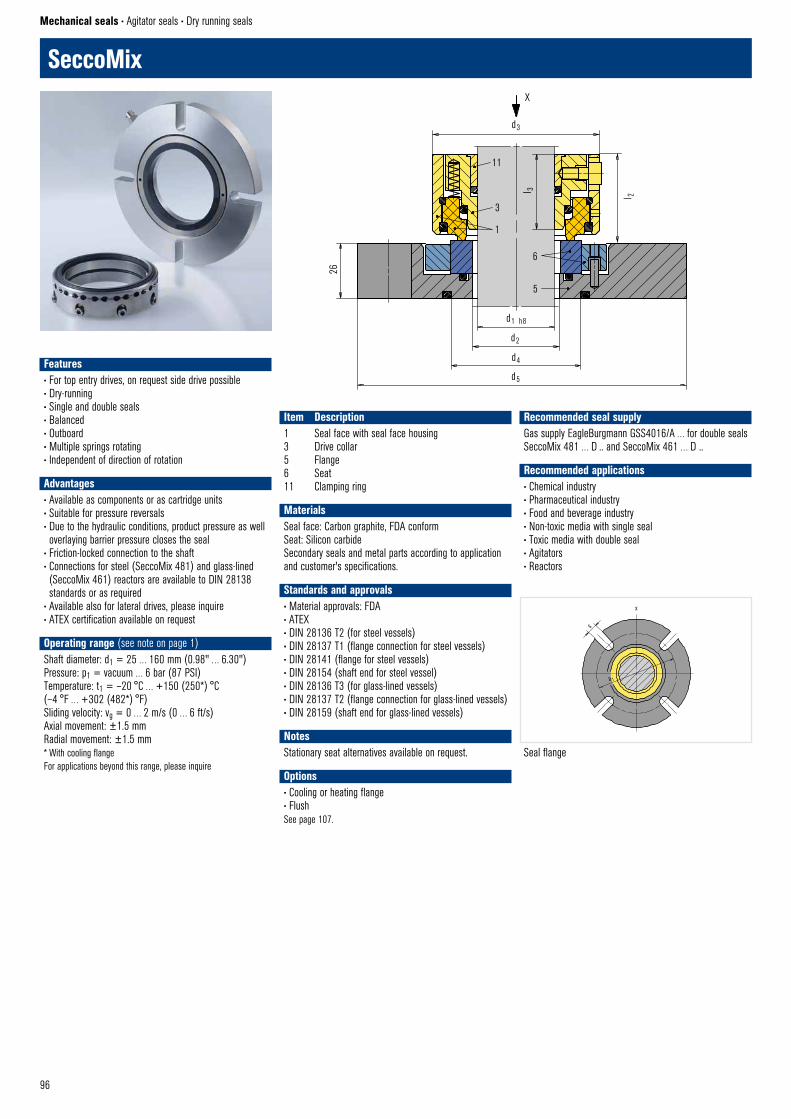
96
x
s
a 1
SeccoMix © EagleBurgmannSeal flange
SeccoMix
Mechanical seals • Agitator seals • Dry running seals
Item Description1 Seal face with seal face housing3 Drive collar5 Flange6 Seat 11 Clamping ring
Features• For top entry drives, on request side drive possible• Dry-running • Single and double seals• Balanced• Outboard• Multiple springs rotating• Independent of direction of rotation• Advantages• Available as components or as cartridge units• Suitable for pressure reversals• Due to the hydraulic conditions, product pressure as well overlaying barrier pressure closes the seal
• Friction-locked connection to the shaft• Connections for steel (SeccoMix 481) and glass-lined (SeccoMix 461) reactors are available to DIN 28138 standards or as required
• Available also for lateral drives, please inquire• ATEX certification available on request• Operating range (see note on page 1)Shaft diameter: d1 = 25 … 160 mm (0.98" … 6.30")Pressure: p1 = vacuum … 6 bar (87 PSI)Temperature: t1 = –20 °C … +150 (250*) °C (–4 °F … +302 (482*) °F)Sliding velocity: vg = 0 … 2 m/s (0 … 6 ft/s)Axial movement: ±1.5 mmRadial movement: ±1.5 mm* With cooling flangeFor applications beyond this range, please inquire
MaterialsSeal face: Carbon graphite, FDA conformSeat: Silicon carbideSecondary seals and metal parts according to application and customer's specifications.
Standards and approvals• Material approvals: FDA• ATEX• DIN 28136 T2 (for steel vessels)• DIN 28137 T1 (flange connection for steel vessels)• DIN 28141 (flange for steel vessels)• DIN 28154 (shaft end for steel vessel)• DIN 28136 T3 (for glass-lined vessels) • DIN 28137 T2 (flange connection for glass-lined vessels)• DIN 28159 (shaft end for glass-lined vessels)
NotesStationary seat alternatives available on request.
Options• Cooling or heating flange• FlushSee page 107.
Recommended seal supplyGas supply EagleBurgmann GSS4016/A … for double seals SeccoMix 481 … D .. and SeccoMix 461 … D ..
Recommended applications• Chemical industry• Pharmaceutical industry• Food and beverage industry• Non-toxic media with single seal• Toxic media with double seal• Agitators• Reactors
26
11
3
1
6
5
X
d3
d1 h8
d2
d4
d5
l 3 l 2

97
Dimensions in mmd1 (mm) d1 (inch) d2 d3 d4 d5 l2 l3 a1(min.) a1(max.) s25 1.000 34 68 – 148 41.5 35 100 132 1128 1.125 34 68 55 148 41.5 35 100 132 1130 – 34 68 55 148 41.5 35 100 132 1132 1.250 39 73 60 153 41.5 35 105 137 1135 1.375 39 73 60 153 41.5 35 105 137 1138 1.500 44 78 65 158 41.5 35 110 142 1140 – 44 78 65 158 41.5 35 110 142 1145 1.625 49 83 68 163 41.5 35 115 152 11– 1.750 49 83 68 163 41.5 35 115 152 1148 1.875 54 88 73 178 41.5 35 125 160 1450 – 54 88 73 178 41.5 35 125 160 1455 2.000 59 93 78 183 41.5 35 130 165 14– 2.125 59 93 78 183 41.5 35 130 165 1460 2.250 64 98 85 188 41.5 35 135 170 1465 2.375 69 103 90 193 44.5 35 140 175 14– 2.500 69 103 90 193 44.5 35 140 175 1470 2.625 74 108 95 198 44.5 38 145 180 14– 2.750 74 108 95 198 44.5 38 145 180 1475 2.875 79 113 100 203 44.5 38 150 185 1480 3.000 84 118 105 208 44.5 38 155 190 1485 3.250 89 123 110 213 44.5 38 160 195 1490 3.500 94 128 115 218 44.5 38 165 200 1495 3.750 99 133 120 223 44.5 38 170 205 14
100 – 104 138 125 228 44.5 38 175 210 14105 4.000 109 143 130 233 44.5 38 180 215 14110 4.250 114 148 135 238 44.5 38 185 220 14115 4.500 119 153 140 267 44.5 38 196 243 18125 4.750 129 163 150 277 44.5 38 206 253 18140 5.000 144 178 165 297 44.5 38 221 273 18– 5.250 144 178 165 297 44.5 38 221 273 18– 5.500 144 178 165 297 44.5 38 221 273 18150 5.750 154 188 175 307 44.5 38 231 283 18160 6.000 164 198 185 317 44.5 38 241 293 18– 6.250 164 198 185 317 44.5 38 241 293 18
SeccoMix1-11The SeccoMix1-11 is equipped in addition with a sleeve for trapping any abraded particles from the seal face. Contamination of the medium in the container is thus ruled out. The sleeve can be cleaned through a flushing bore. Please note: diameters (d2 to d5) increase to the next possible design size.
SeccoMix 481Single seal. Dimensions see page 107
SeccoMix 481LSingle seal with integrated floating bearing.
SeccoMix 451All types of the SeccoMix 481 range available for unstepped shafts (all diameters). Seal identification: SeccoMix 451 … Customized design or e. g. different drives (torque transmissions) are available.
SeccoMix 461/(491)For glass-lined vessels. Dimensions see page 109
SeccoMix 481-DDouble seal
SeccoMix 481L-DDouble seal with integrated floating bearing
These seals are designed to be self-closing on the product side, i.e. they will remain closed even with pressure variations or a pressure reversal. Operation is optionally the same as for the single version. In view of the mechanical seal on the atmosphere side it can be used as a buffer pressurized double seal . The barrier pressure should be 0.5 … 1.0 bar (7.25 … 15 PSI) above pressure to be sealed.
Product variants
SeccoMix 481 © EagleBurgmannSeccoMix 481L © EagleBurgmann
D
C
G
SeccoMix 481-D © EagleBurgmannSeccoMix 481L-D © EagleBurgmann
D
C
G
SeccoMix1–11 Flush © EagleBurgmann
X
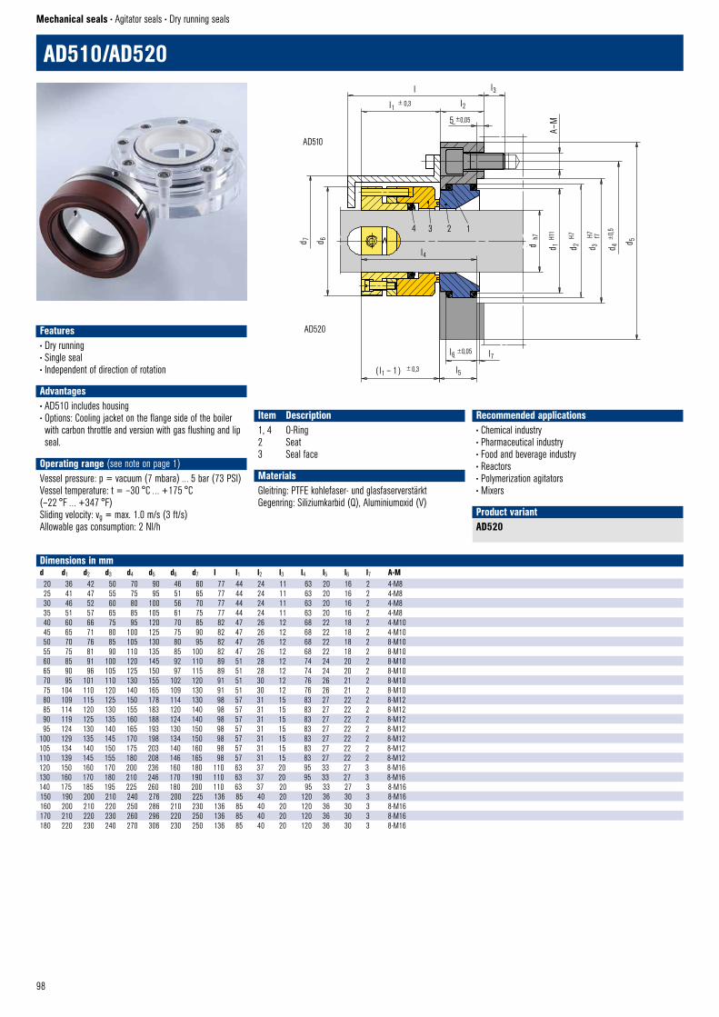
98
4 3 2 1
d 6
l4
d 7
d 1 H1
1
d 2d h7
d 3 d 4
H7 ±0,
5
l1
l3
l2
5 ±0,05
± 0,3
( l1 – 1 ) ± 0,3 l5
l6 ±0,05
l7
AD510-AD520 © EagleBurgmann
AD510
AD520
d 5
A–M
l
H7 f7
AD510/AD520
Mechanical seals • Agitator seals • Dry running seals
Item Description1, 4 O-Ring2 Seat3 Seal face
AD520Product variant
Dimensions in mmd d1 d2 d3 d4 d5 d6 d7 l l1 l2 l3 l4 l5 l6 l7 A-M20 36 42 50 70 90 46 60 77 44 24 11 63 20 16 2 4-M825 41 47 55 75 95 51 65 77 44 24 11 63 20 16 2 4-M830 46 52 60 80 100 56 70 77 44 24 11 63 20 16 2 4-M835 51 57 65 85 105 61 75 77 44 24 11 63 20 16 2 4-M840 60 66 75 95 120 70 85 82 47 26 12 68 22 18 2 4-M1045 65 71 80 100 125 75 90 82 47 26 12 68 22 18 2 4-M1050 70 76 85 105 130 80 95 82 47 26 12 68 22 18 2 8-M1055 75 81 90 110 135 85 100 82 47 26 12 68 22 18 2 8-M1060 85 91 100 120 145 92 110 89 51 28 12 74 24 20 2 8-M1065 90 96 105 125 150 97 115 89 51 28 12 74 24 20 2 8-M1070 95 101 110 130 155 102 120 91 51 30 12 76 26 21 2 8-M1075 104 110 120 140 165 109 130 91 51 30 12 76 26 21 2 8-M1080 109 115 125 150 178 114 130 98 57 31 15 83 27 22 2 8-M1285 114 120 130 155 183 120 140 98 57 31 15 83 27 22 2 8-M1290 119 125 135 160 188 124 140 98 57 31 15 83 27 22 2 8-M1295 124 130 140 165 193 130 150 98 57 31 15 83 27 22 2 8-M12
100 129 135 145 170 198 134 150 98 57 31 15 83 27 22 2 8-M12105 134 140 150 175 203 140 160 98 57 31 15 83 27 22 2 8-M12110 139 145 155 180 208 146 165 98 57 31 15 83 27 22 2 8-M12120 150 160 170 200 236 160 180 110 63 37 20 95 33 27 3 8-M16130 160 170 180 210 246 170 190 110 63 37 20 95 33 27 3 8-M16140 175 185 195 225 260 180 200 110 63 37 20 95 33 27 3 8-M16150 190 200 210 240 276 200 225 136 85 40 20 120 36 30 3 8-M16160 200 210 220 250 286 210 230 136 85 40 20 120 36 30 3 8-M16170 210 220 230 260 296 220 250 136 85 40 20 120 36 30 3 8-M16180 220 230 240 270 306 230 250 136 85 40 20 120 36 30 3 8-M16
Features• Dry running• Single seal• Independent of direction of rotation • Advantages• AD510 includes housing• Options: Cooling jacket on the flange side of the boiler with carbon throttle and version with gas flushing and lip seal.
• Operating range (see note on page 1)Vessel pressure: p = vacuum (7 mbara) … 5 bar (73 PSI)Vessel temperature: t = –30 °C … +175 °C (–22 °F … +347 °F)Sliding velocity: vg = max. 1.0 m/s (3 ft/s)Allowable gas consumption: 2 Nl/h
MaterialsGleitring: PTFE kohlefaser- und glasfaserverstärktGegenring: Siliziumkarbid (Q), Aluminiumoxid (V)
Recommended applications• Chemical industry• Pharmaceutical industry• Food and beverage industry• Reactors• Polymerization agitators• Mixers

99
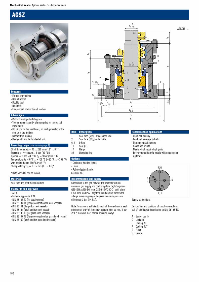
100
AGSZ
Mechanical seals • Agitator seals • Gas-lubricated seals
Item Description1 Seal face (Q19), atmosphere side2 Seal face (Q1), product side6, 7 O-Ring11 Seat (Q1)17 Flange22 Clamping ring
Recommended applications• Chemical industry• Food and beverage industry• Pharmaceutical industry• Gases and liquids• Media which require high purity• Environmental harmful media with double seals• Agitators
Supply connections
Designation and positions of supply connections, pull-off and jacket threads acc. to DIN 28138 T3.
A Barrier gas INC LeakageE Cooling INF Cooling OUTS FlushG Grease
Options• Cooling or heating flange• Flush• Polymerization barrierSee page 107.
Recommended seal supplyConnection to the gas network (or cylinder) with an upstream gas supply and control system EagleBurgmann GSS4016/A250-D1 resp. GSS4016/A350-D1 with alarm FIAH, FIAL and PIAL, together with two flow meters for a large measuring range. Required minimum pressure difference: 3 bar (44 PSI).
Note: To assure a sufficient supply of the mechanical seal, pressure at entry of the supply system must be min. 2 bar (29 PSI) above max. barrier pressure always.
d3 h8
1
1)
G
C
d7 h61)
22
11
2
17
A
2 x M2
1,5
30° do
k
AGSZ © EagleBurgmann
8,5l 1
d2
L 2l 2
6
7
a
d4 e8
d1
L 1l 3
AGSZ481...
AC
S
E, G
F, G
AGSZ © EagleBurgmann
M1
M2
Features• For top entry drives• Gas-lubricated• Double seal• Balanced• Independent of direction of rotation • Advantages• Centrally arranged rotating seat • Torque transmission by clamping ring for large axial movements
• No friction on the seal faces, no heat generated at the seal or in the medium
• Contact-free running • Ready-to-fit and factory-tested unit• Operating range (see note on page 1)Shaft diameter: d3 = 40 … 220 mm (1.6" … 8.7")Pressure p1 = vacuum … 6 bar (87 PSI), Δp min. = 3 bar (44 PSI), p3 = 9 bar (131 PSI)Temperature: t1 = 0 °C … +150 °C (+32 °F … +302 °F), with cooling flange 250 °C (482 °F)Sliding velocity: vg = 0 … 2 m/s (0 … 7 ft/s)*
* Up to 5 m/s (16 ft/s) on request.
MaterialsSeal face and seat: Silicon carbide
Standards and approvals• ATEX• Material approvals: FDA• DIN 28136 T2 (for steel vessels)• DIN 28137 T1 (flange connection for steel vessels)• DIN 28141 (flange for steel vessels)• DIN 28154 (shaft end for steel vessel)• DIN 28136 T3 (for glass-lined vessels) • DIN 28137 T2 (flange connection for glass-lined vessels)• DIN 28159 (shaft end for glass-lined vessels)
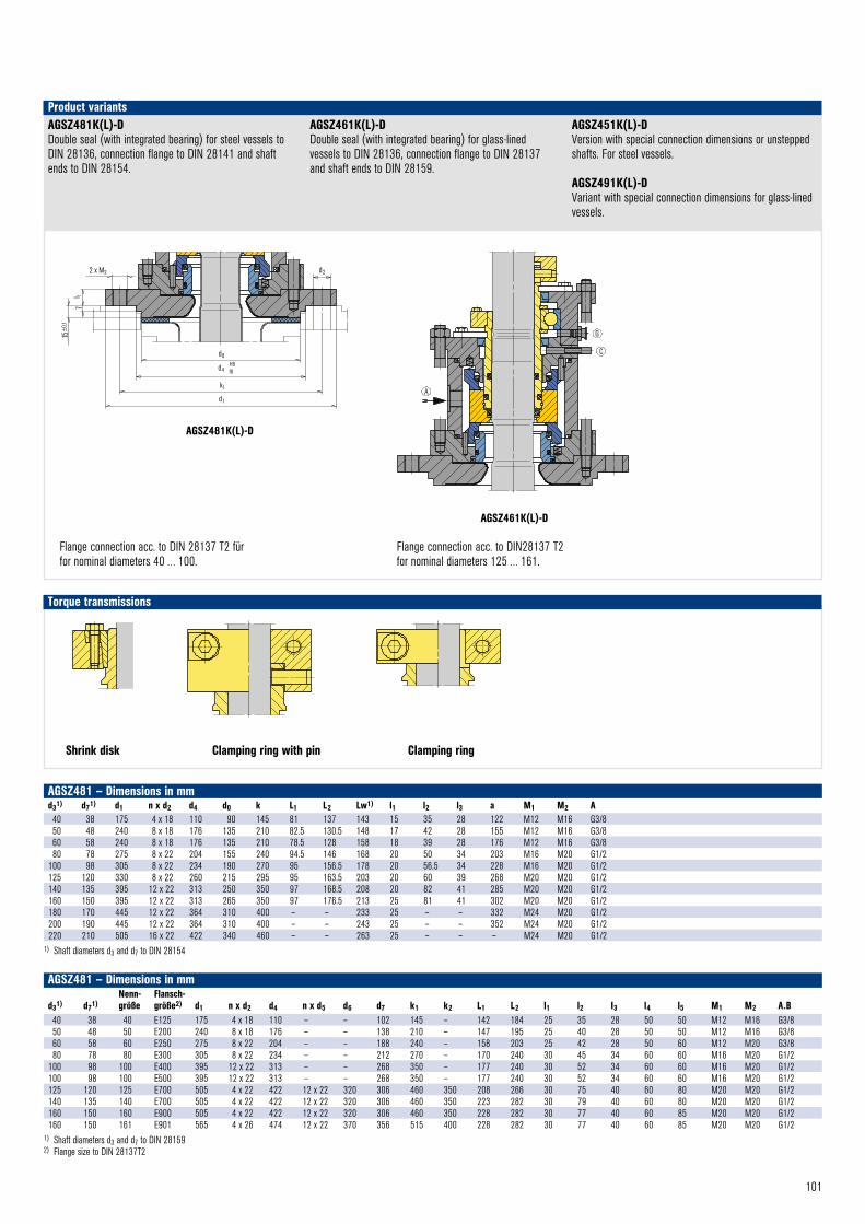
101
AGSZ481 – Dimensions in mm
d31) d71)Nenn- größe
Flansch-größe2) d1 n x d2 d4 n x d5 d6 d7 k1 k2 L1 L2 l1 l2 I3 l4 l5 M1 M2 A.B
40 38 40 E125 175 4 x 18 110 – – 102 145 – 142 184 25 35 28 50 50 M12 M16 G3/8 50 48 50 E200 240 8 x 18 176 – – 138 210 – 147 195 25 40 28 50 50 M12 M16 G3/8 60 58 60 E250 275 8 x 22 204 – – 188 240 – 158 203 25 42 28 50 60 M12 M20 G3/8 80 78 80 E300 305 8 x 22 234 – – 212 270 – 170 240 30 45 34 60 60 M16 M20 G1/2
100 98 100 E400 395 12 x 22 313 – – 268 350 – 177 240 30 52 34 60 60 M16 M20 G1/2 100 98 100 E500 395 12 x 22 313 – – 268 350 – 177 240 30 52 34 60 60 M16 M20 G1/2 125 120 125 E700 505 4 x 22 422 12 x 22 320 306 460 350 208 266 30 75 40 60 80 M20 M20 G1/2 140 135 140 E700 505 4 x 22 422 12 x 22 320 306 460 350 223 282 30 79 40 60 80 M20 M20 G1/2 160 150 160 E900 505 4 x 22 422 12 x 22 320 306 460 350 228 282 30 77 40 60 85 M20 M20 G1/2 160 150 161 E901 565 4 x 26 474 12 x 22 370 356 515 400 228 282 30 77 40 60 85 M20 M20 G1/2
1) Shaft diameters d3 and d7 to DIN 28159 2) Flange size to DIN 28137T2
AGSZ481 – Dimensions in mmd31) d71) d1 n x d2 d4 d0 k L1 L2 Lw1) l1 l2 l3 a M1 M2 A40 38 175 4 x 18 110 90 145 81 137 143 15 35 28 122 M12 M16 G3/850 48 240 8 x 18 176 135 210 82.5 130.5 148 17 42 28 155 M12 M16 G3/860 58 240 8 x 18 176 135 210 78.5 128 158 18 39 28 176 M12 M16 G3/880 78 275 8 x 22 204 155 240 94.5 146 168 20 50 34 203 M16 M20 G1/2
100 98 305 8 x 22 234 190 270 95 156.5 178 20 56.5 34 228 M16 M20 G1/2125 120 330 8 x 22 260 215 295 95 163.5 203 20 60 39 268 M20 M20 G1/2140 135 395 12 x 22 313 250 350 97 168.5 208 20 82 41 285 M20 M20 G1/2160 150 395 12 x 22 313 265 350 97 176.5 213 25 81 41 302 M20 M20 G1/2180 170 445 12 x 22 364 310 400 – – 233 25 – – 332 M24 M20 G1/2200 190 445 12 x 22 364 310 400 – – 243 25 – – 352 M24 M20 G1/2220 210 505 16 x 22 422 340 460 – – 263 25 – – – M24 M20 G1/2
1) Shaft diameters d3 and d7 to DIN 28154
Klem
mrin
g ©
Eag
leBur
gman
n
Dreh
mom
entü
bertr
agun
g
Torque transmissions
Shrink disk Clamping ring with pin Clamping ring
AGSZ481K(L)-DDouble seal (with integrated bearing) for steel vessels to DIN 28136, connection flange to DIN 28141 and shaft ends to DIN 28154.
AGSZ461K(L)-DDouble seal (with integrated bearing) for glass-lined vessels to DIN 28136, connection flange to DIN 28137 and shaft ends to DIN 28159.
AGSZ451K(L)-DVersion with special connection dimensions or unstepped shafts. For steel vessels.
AGSZ491K(L)-DVariant with special connection dimensions for glass-lined vessels.
Product variants
Flange connection acc. to DIN28137 T2for nominal diameters 125 … 161.
Flange connection acc. to DIN 28137 T2 für for nominal diameters 40 … 100.
AGSZ © EagleBurgmann
Flanschanschlussnach DIN 28137 T2für Nenngrösse40 bis 100.
2 x M2
d8
d4
k1
d1
H8f8
l 17
15±
0,1
d2
G
C
A
AGSZ461 © EagleBurgmann
Klem
mrin
g m
it St
ift ©
Eag
leBur
gman
n
Dreh
mom
entü
bertr
agun
g
AGSZ481K(L)-D
AGSZ461K(L)-D
T-Shrink disk II © EagleBurgmann
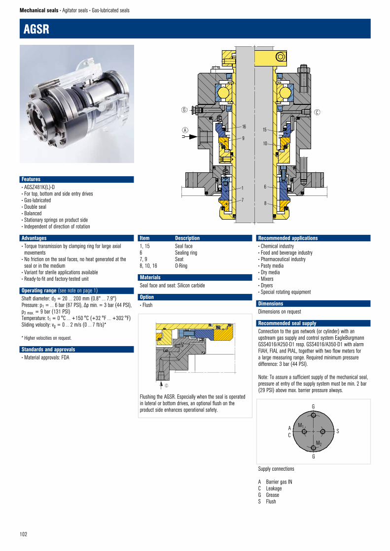
102
AGSR
Mechanical seals • Agitator seals • Gas-lubricated seals
Item Description1, 15 Seal face6 Sealing ring7, 9 Seat8, 10, 16 O-Ring AGSR58 © EagleBurgmann
G
A
C
16
9
15
10
1
7
6
8
AC
S
G
G
AGSR © EagleBurgmann
M1
M2
Flushing the AGSR. Especially when the seal is operated in lateral or bottom drives, an optional flush on the product side enhances operational safety.
Supply connections
A Barrier gas INC LeakageG GreaseS Flush
Spuelung AGSR © EagleBurgmann
C
Recommended applications• Chemical industry• Food and beverage industry• Pharmaceutical industry• Pasty media• Dry media• Mixers• Dryers• Special rotating equipment
DimensionsDimensions on request
Recommended seal supplyConnection to the gas network (or cylinder) with anupstream gas supply and control system EagleBurgmannGSS4016/A250-D1 resp. GSS4016/A350-D1 with alarmFIAH, FIAL and PIAL, together with two flow meters fora large measuring range. Required minimum pressuredifference: 3 bar (44 PSI).
Note: To assure a sufficient supply of the mechanical seal,pressure at entry of the supply system must be min. 2 bar(29 PSI) above max. barrier pressure always.
MaterialsSeal face and seat: Silicon carbide
Option• Flush
Features• AGSZ481K(L)-D• For top, bottom and side entry drives• Gas-lubricated• Double seal• Balanced• Stationary springs on product side• Independent of direction of rotation
• Advantages• Torque transmission by clamping ring for large axial movements
• No friction on the seal faces, no heat generated at the seal or in the medium
• Variant for sterile applications available• Ready-to-fit and factory-tested unit• Operating range (see note on page 1)Shaft diameter: d3 = 20 … 200 mm (0.8" … 7.9")Pressure: p1 = … 6 bar (87 PSI), Δp min. = 3 bar (44 PSI), p3 max. = 9 bar (131 PSI)Temperature: t1 = 0 °C … +150 °C (+32 °F … +302 °F)Sliding velocity: vg = 0 … 2 m/s (0 … 7 ft/s)*
* Higher velocities on request.
Standards and approvals• Material approvals: FDA

103
AGSR5(L)-DDouble seal (with floating bearing for the shaft). If the seal has to run in the product, please inquire.
Product variantsAGSR3(L)-DDouble seal (with floating bearing for the shaft) for sterile applications. The dead-space-free design with polished surfaces on the product side meets the requirements for sterile processes.
AGSR38 © EagleBurgmann
G
A
B
C
Klem
mrin
g ©
Eag
leBur
gman
n
Dreh
mom
entü
bertr
agun
g
Torque transmissions
Shrink disk Clamping ring with pin Clamping ring
Klem
mrin
g m
it St
ift ©
Eag
leBur
gman
n
Dreh
mom
entü
bertr
agun
g
T-Shrink disk II © EagleBurgmann
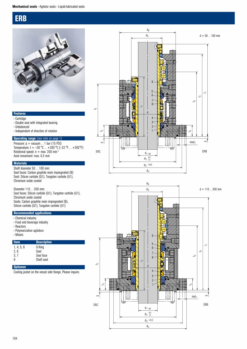
104
ERB
Mechanical seals • Agitator seals • Liquid-lubricated seals
Features• Cartridge• Double seal with integrated bearing• Unbalanced• Independent of direction of rotation
• Operating range (see note on page 1)Pressure: p = vacuum … 1 bar (15 PSI)Temperature: t = –30 °C … +200 °C (–22 °F … +392°F)Rotational speed: n = max. 200 min-1
Axial movement: max. 0.3 mm
MaterialsShaft diameter 50 … 100 mm:Seal faces: Carbon graphite resin impregnated (B)Seat: Silicon carbide (Q1), Tungsten carbide (U1), Chromium oxide coated
Diameter 110 … 200 mm:Seal faces: Silicon carbide (Q1), Tungsten carbide (U1), Chromium oxide coatedSeats: Carbon graphite resin impregnated (B), Silicon carbide (Q1), Tungsten carbide (U1)
Recommended applications• Chemical industry• Food and beverage industry• Reactors• Polymerization agitators• Mixers
Item Description1, 4, 5, 8 O-Ring2, 6 Seat3, 7 Seal face9 Shaft seal
OptionenCooling jacket on the vessel side flange. Please inquire.
9
56
78l 1
d
4321
l 3
l 4
mxd7
5
d1 h6
d2
d3 ±0,5
d4
l 2
l 35
l 2l 1
d6
d5
ERB – ERC 50–100 © EagleBurgmann
ERC ERB
H7f7
d = 50 … 100 mm
nxd7
9
56
78
4
321
l 1
d
d1 h6
d2
d3 ±0,5
d4
5
l 4l 3
l 2
l 1
d6
d5
l 2
l 3
5
ERB–ERC 110–200 © EagleBurgmann
ERC
H7f7
ERB
d = 110 … 200 mm

105
Torque transmissions
Set screw with conepoint for diameterd1 >120 mm and/or vessel pressurep >1 barg
Drive key Shrink disk
ERB – Dimensions in mmd d1 d2 d3 d4 d5 d6 d7 l1 l2 l3 l4 n Lagertyp50 35 135 170 195 61 134 14 268 237 185 30 8 #7210ADB60 45 145 180 205 75 144 14 283 252 197 30 8 #7212ADB70 55 155 190 215 85 154 14 293 262 205 30 8 #7014ADB80 65 165 200 225 95 164 14 303 272 207 30 8 #7016ADB90 75 175 210 235 105 174 14 323 287 219 30 8 #7018ADB
100 85 185 220 245 115 184 14 323 287 219 30 8 #7020ADB110 95 205 240 265 125 218 14 333 291 216 30 8 #7022ADB120 105 215 261 289 135 235 19 371 309 233 35 12 #7024ADB130 110 225 271 299 145 245 19 364 322 238 35 12 #7026ADB140 120 235 281 309 159 255 19 369 322 238 35 12 #7028ADB150 130 280 335 375 169 295 23 424 377 288 45 12 #7030ADB160 140 290 345 385 179 305 23 433 386 291 45 12 #7032ADB170 150 300 355 395 189 315 23 452 400 295 45 12 #7034ADB180 160 310 365 405 199 328 23 458 406 299 45 12 #7036ADB190 170 320 375 415 209 338 23 473 416 309 45 12 #7038ADB200 180 330 390 430 219 358 23 483 426 312 45 12 #7040ADB
ERC – Dimensions in mmd d1 d2 d3 d4 d5 d6 d7 l1 l2 l3 n50 35 135 170 195 66 134 14 162 144 30 860 45 145 180 205 76 144 14 175 157 30 870 55 155 190 215 86 154 14 186 168 30 880 65 165 200 225 96 164 14 186 168 30 890 75 175 210 235 110 174 14 198 178 30 8
100 85 185 220 245 120 184 14 198 178 30 8110 95 205 240 265 130 218 14 200 173 30 8120 105 215 261 289 140 235 19 217 190 35 12130 110 225 271 299 154 245 19 222 190 35 12140 120 235 281 309 164 255 19 222 190 35 12150 130 280 335 375 174 295 23 261 229 45 12160 140 290 345 385 184 305 23 263 231 45 12170 150 300 355 395 194 315 23 263 231 45 12180 160 310 365 405 204 328 23 263 231 45 12190 170 320 375 415 214 338 23 273 241 45 12200 180 330 390 430 224 358 23 277 245 45 12
To
rque
tran
smiss
ion
Drive
key
© E
agleB
urgm
ann
Set s
crew
with
con
e po
int ©
Eag
leBur
gman
n
T-Shrink disk II © EagleBurgmann
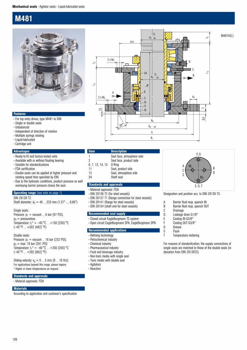
106
34
15 11142
d1
k
d4 e8
d0
M481 © EagleBurgmann
30°
l w
1)d3 h8
1)d7 h6
ø a
2 x M1
2 x M21,5
L 1l 2
l 2
G
C
B
L 2
d2
l 18,
5
6A
M481
Mechanical seals • Agitator seals • Liquid-lubricated seals
Item Description1 Seal face, atmosphere side2 Seal face, product side6, 7, 13, 14, 15 O-Ring11 Seat, product side12 Seat, atmosphere side34 Shaft seal
Standards and approvals• Material approvals: FDA • DIN 28136 T2 (for steel vessels)• DIN 28137 T1 (flange connection for steel vessels)• DIN 28141 (flange for steel vessels)• DIN 28154 (shaft end for steel vessels)
Recommended seal supply• Closed circuit EagleBurgmann TS system• Open circuit EagleBurgmann SPA, EagleBurgmann SPN
Recommended applications• Refining technology• Petrochemical industry• Chemical industry• Pharmaceutical industry• Food and beverage industry• Non-toxic media with single seal• Toxic media with double seal• Agitators• Reactors
Designation and position acc. to DIN 28138 T3.
A Barrier fluid resp. quench INB Barrier fluid resp. quench OUTC DrainageD Leakage drain G1/8"E Cooling IN G3/8"F Cooling OUT G3/8"G GreaseS FlushT Temperature metering
For reasons of standardization, the supply connections of single seals are matched to those of the double seals (in deviation from DIN 28138T3).
M481K(L)
ACS
BD
E, G, T
F, G
M 481 © EagleBurgmann
M1
M2
Features• For top entry drives, type M481 to DIN• Single or double seals• Unbalanced• Independent of direction of rotation• Multiple springs rotating• Liquid-lubricated• Cartridge unit • Advantages• Ready-to-fit and factory-tested units• Available with or without floating bearing• Suitable for standardizations• FDA certification• Double seals can be applied at higher pressure and rotating speed than specified by DIN
• Due to the hydraulic conditions, product pressure as well overlaying barrier pressure closes the seal.
Operating range (see note on page 1)DIN 28138 T2Shaft diameter: d3 = 40 … 220 mm (1.57" .... 8.66")
Single seals: Pressure: p1 = vacuum … 6 bar (87 PSI), p3 = pressurelessTemperature: t1* = –40 °C … +150 (250) °C (–40 °F … +302 (482) °F)
Double seals: Pressure: p1 = vacuum … 16 bar (232 PSI), p3 = max. 18 bar (261 PSI)Temperature: t1* = –40 °C … +200 (350) °C (–40 °F … +392 (662) °F)
Sliding velocity: vg = 0 … 5 m/s (0 … 16 ft/s)For applications beyond this range, please inquire.* Higher or lower temperatures on request.
Standards and approvals• Material approvals: FDA
MaterialsAccording to application and customer’s specification
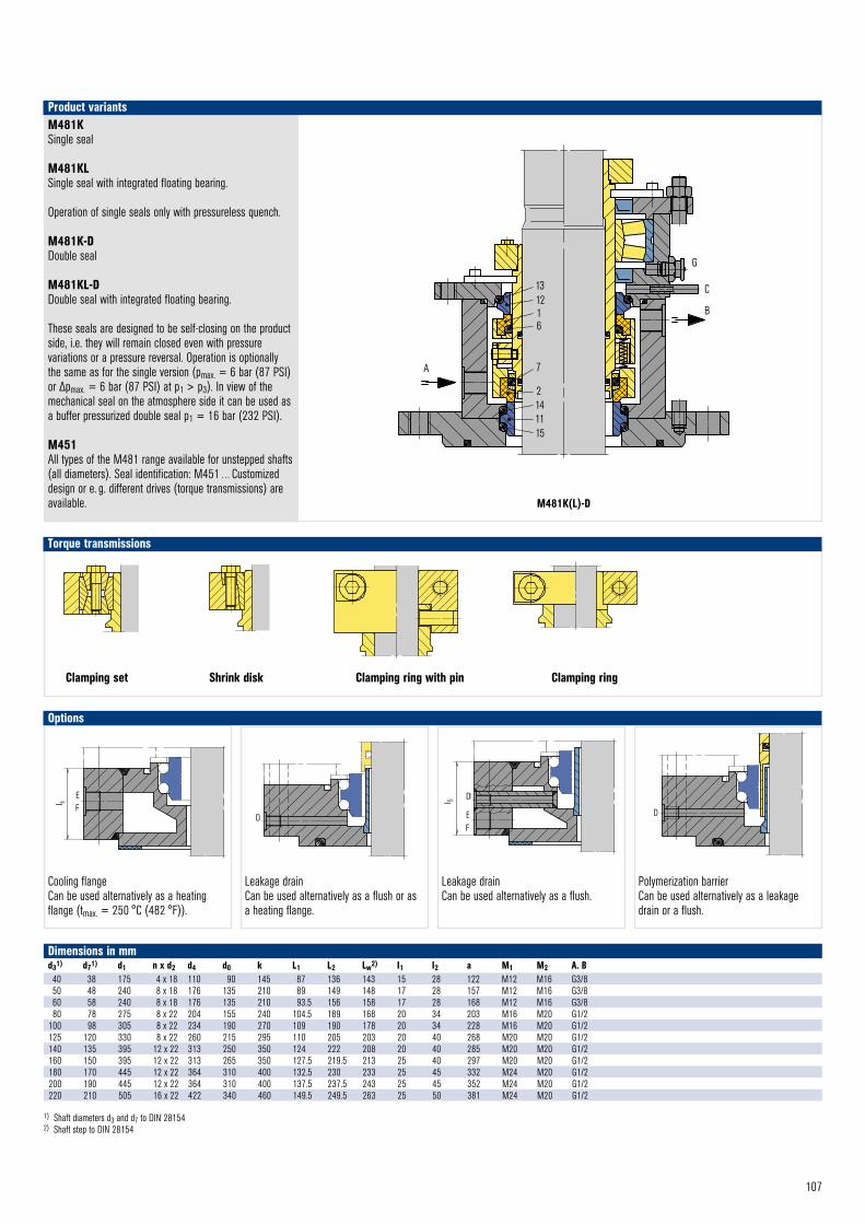
107
M481K(L)-D
M481KSingle seal
M481KLSingle seal with integrated floating bearing.
Operation of single seals only with pressureless quench.
M481K-D Double seal
M481KL-D Double seal with integrated floating bearing.
These seals are designed to be self-closing on the product side, i.e. they will remain closed even with pressure variations or a pressure reversal. Operation is optionally the same as for the single version (pmax. = 6 bar (87 PSI) or Δpmax. = 6 bar (87 PSI) at p1 > p3). In view of the mechanical seal on the atmosphere side it can be used as a buffer pressurized double seal p1 = 16 bar (232 PSI).
M451All types of the M481 range available for unstepped shafts (all diameters). Seal identification: M451 … Customized design or e. g. different drives (torque transmissions) are available.
Product variants
Dimensions in mmd31) d71) d1 n x d2 d4 d0 k L1 L2 Lw2) I1 I2 a M1 M2 A. B40 38 175 4 x 18 110 90 145 87 136 143 15 28 122 M12 M16 G3/850 48 240 8 x 18 176 135 210 89 149 148 17 28 157 M12 M16 G3/860 58 240 8 x 18 176 135 210 93.5 156 158 17 28 168 M12 M16 G3/880 78 275 8 x 22 204 155 240 104.5 189 168 20 34 203 M16 M20 G1/2
100 98 305 8 x 22 234 190 270 109 190 178 20 34 228 M16 M20 G1/2125 120 330 8 x 22 260 215 295 110 205 203 20 40 268 M20 M20 G1/2140 135 395 12 x 22 313 250 350 124 222 208 20 40 285 M20 M20 G1/2160 150 395 12 x 22 313 265 350 127.5 219.5 213 25 40 297 M20 M20 G1/2180 170 445 12 x 22 364 310 400 132.5 230 233 25 45 332 M24 M20 G1/2200 190 445 12 x 22 364 310 400 137.5 237.5 243 25 45 352 M24 M20 G1/2220 210 505 16 x 22 422 340 460 149.5 249.5 263 25 50 381 M24 M20 G1/2
1) Shaft diameters d3 and d7 to DIN 281542) Shaft step to DIN 28154
131216
7
2141115
A
G
C
B
M481KL – D © EagleBurgmann
Torque transmissions
Clamping set Shrink disk Clamping ring with pin Clamping ring
Klem
mrin
g m
it St
ift ©
Eag
leBur
gman
n
Dreh
mom
entü
bertr
agun
g
Klem
mrin
g ©
Eag
leBur
gman
n
Dreh
mom
entü
bertr
agun
g
Torq
ue tr
ansm
ission
Clam
pings
et ©
Eag
leBur
gman
n
T-Shrink disk II © EagleBurgmann
D
Leckabzug (alternativ anwendbar als Spülung)
Leckabzug © EagleBurgmann
with leakage drain (can also be used as a flush)
Leakage drain or flush © EagleBurgmann
D
Polymerisationssperre © EagleBurgmann
D
Cooling flangeCan be used alternatively as a heating flange (tmax. = 250 °C (482 °F)).
Leakage drainCan be used alternatively as a flush or as a heating flange.
Leakage drainCan be used alternatively as a flush.
Polymerization barrierCan be used alternatively as a leakage drain or a flush.
l s
EF
Kühlflansch tmax = 350 °C(alternativ anwendbar als Heizflansch)
Kühlflansch © EagleBurgmann
F
l s
E
Cooling or heating flange © EagleBurgmann
Options
Leckabzug und Kuehlflansch © EagleBurgmann
Leckabzug und Kuehlflansch
l 5
FE
D
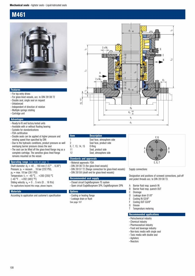
108
L 1l 2
2 x M1
2 x M2
A
l 1
15 ±
0,1
7
d8
d4 H8 f8
k1
d1
7
2
141115 d3 h8
131216
d7 h6
d2
L 2
G
C
B
M461KL – D © EagleBurgmann
l 3
l 5 l 4
M461
Mechanical seals • Agitator seals • Liquid-lubricated seals
Recommended applications• Petrochemical industry• Chemical industry• Pharmaceutical industry• Food and beverage industry• Non-toxic media with single seal• Toxic media with double seal• Agitators• Reactors
Item Description1 Seal face, atmosphere side2 Seal face, product side6, 7, 13, 14, 15 O-Ring11 Seat, product side12 Seat, atmosphere side
Supply connections
Designation and positions of screwed connections, pull-off and jacket threads acc. to DIN 28138 T3.
A Barrier fluid resp. quench INB Barrier fluid resp. quench OUTC DrainageD Leakage drain G1/8"E Cooling IN G3/8"F Cooling OUT G3/8"G GreaseT Temperature metering
AC
BD
E, G, T
F, G
M 461 © EagleBurgmann
M1
M2
Features• For top entry drives• For glass-lined vessels, acc. to DIN 28138 T2• Double seal, single seal on request• Unbalanced• Independent of direction of rotation• Multiple springs rotating• Cartridge unit • Advantages• Ready-to-fit and factory-tested units• Available with or without floating bearing• Suitable for standardizations• FDA certification• Double seals can be applied at higher pressure and rotating speed than specified by DIN
• Due to the hydraulic conditions, product pressure as well overlaying barrier pressure closes the seal
• The seal can be lifted off the glass-lined flange ring as a complete cartridge. The sensitive glass lined flange remains mounted on the vessel.
Operating range (see note on page 1)Shaft diameter: d3 = 40 … 160 mm (1.57" … 6.30")Pressure: p1 = vacuum … 16 bar (232 PSI), p3 = max. 18 bar (261 PSI)Temperature: t1 = –40 °C … +200 (250) °C (–40 °F … +392 (482) °F)Sliding velocity: vg = 0 … 5 m/s (0 … 16 ft/s)For applications beyond this range, please inquire.
MaterialsAccording to application and customer’s specification
Standards and approvals• Material approvals: FDA • DIN 28136 T3 (for glass-lined vessels)• DIN 28137 T2 (flange connection for glass-lined vessels)• DIN 28159 (shaft end for glass-lined vessels)
Recommended seal supply• Closed circuit EagleBurgmann TS system• Open circuit EagleBurgmann SPA, EagleBurgmann SPN
Options• Cooling or heating flange• Leakage drain or flushSee page 107
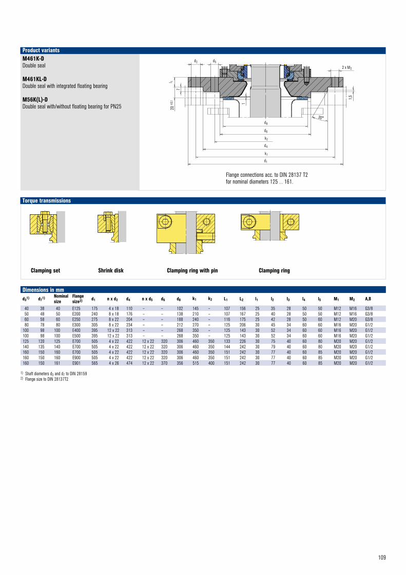
109
M461K-DDouble seal
M461KL-DDouble seal with integrated floating bearing
M56K(L)-DDouble seal with/without floating bearing for PN25
Product variants
d2 d5
l 1
720
±0,1 1
d8
d6
d4
d1
k2
k1
M461 © EagleBurgmann
2 x M2
1,5
30°
Flange connections acc. to DIN 28137 T2for nominal diameters 125 … 161.
Dimensions in mmd31) d71) Nominal
sizeFlange size2) d1 n x d2 d4 n x d5 d6 d8 k1 k2 L1 L2 l1 l2 I3 l4 l5 M1 M2 A,B
40 38 40 E125 175 4 x 18 110 – – 102 145 – 107 156 25 35 28 50 50 M12 M16 G3/8 50 48 50 E200 240 8 x 18 176 – – 138 210 – 107 167 25 40 28 50 50 M12 M16 G3/8 60 58 60 E250 275 8 x 22 204 – – 188 240 – 116 175 25 42 28 50 60 M12 M20 G3/8 80 78 80 E300 305 8 x 22 234 – – 212 270 – 125 206 30 45 34 60 60 M16 M20 G1/2
100 98 100 E400 395 12 x 22 313 – – 268 350 – 125 143 30 52 34 60 60 M16 M20 G1/2 100 98 100 E500 395 12 x 22 313 – – 268 350 – 125 143 30 52 34 60 60 M16 M20 G1/2 125 120 125 E700 505 4 x 22 422 12 x 22 320 306 460 350 133 226 30 75 40 60 80 M20 M20 G1/2 140 135 140 E700 505 4 x 22 422 12 x 22 320 306 460 350 144 242 30 79 40 60 80 M20 M20 G1/2 160 150 160 E700 505 4 x 22 422 12 x 22 320 306 460 350 151 242 30 77 40 60 85 M20 M20 G1/2 160 150 160 E900 505 4 x 22 422 12 x 22 320 306 460 350 151 242 30 77 40 60 85 M20 M20 G1/2 160 150 161 E901 565 4 x 26 474 12 x 22 370 356 515 400 151 242 30 77 40 60 85 M20 M20 G1/2
1) Shaft diameters d3 and d7 to DIN 281592) Flange size to DIN 28137T2
Torque transmissions
Clamping set Shrink disk Clamping ring with pin Clamping ring
Klem
mrin
g m
it St
ift ©
Eag
leBur
gman
n
Dreh
mom
entü
bertr
agun
g
Klem
mrin
g ©
Eag
leBur
gman
n
Dreh
mom
entü
bertr
agun
g
Torq
ue tr
ansm
ission
Clam
pings
et ©
Eag
leBur
gman
n
T-Shrink disk II © EagleBurgmann
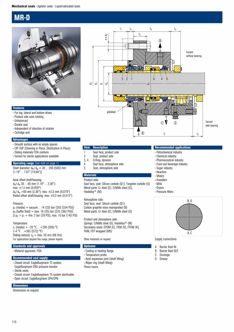
110
MR-D
Mechanical seals • Agitator seals • Liquid-lubricated seals
Recommended applications• Petrochemical industry• Chemical industry• Pharmaceutical industry• Food and beverage industry• Sugar industry• Reactors• Mixers• Kneaders• Mills• Dryers• Pressure filters
Item Description1 Seal face, product side2 Seat, product side3, 4 O-Ring, dynamic4 Seal face, atmosphere side5 Seat, atmosphere side
5
polished
l1 l3 l6 l5l4
d 1n x
d5
d 2d 3 d w
C G
l7 l5
MR34–D © EagleBurgmann
2 3 1 6 4
d n
B
B
A, C
B, G
MR-D © EagleBurgmannSupply connections
A Barrier fluid INB Barrier fluid OUTC DrainageG Grease
Variantwithout bearing
Variantwith bearing
Features• For top, lateral and bottom drives• Product side seat rotating• Unbalanced• Double seal• Independent of direction of rotation• Cartridge unit • Advantages• Smooth surface with no empty spaces• CIP-/SIP (Cleaning in Place, Sterilization in Place)• Sliding materials FDA conform• Variant for sterile applications available
Operating range (see note on page 1)Shaft diameter: dN / dw = 30 … 200 (500) mm (1.18" … 7.87" (19.68”))
Axial offset shaft/housing: dN / dw 30 … 60 mm (1.18" … 2.36"): max. ±1.5 mm (0.059")dN / dw >60 mm (2.36"): max. ±2.0 mm (0.079")Radial offset shaft/housing: max. ±0.3 mm (0.012")
Pressure: p1 (media) = vacuum … 14 (23) bar (203 (334 PSI))p3 (buffer fluid) = max. 16 (25) bar (232 (363 PSI))Δ p3 > p1 = min. 2 bar (29 PSI), max. 10 bar (145 PSI)
Temperature:t1 (media) = –20 °C … +200 (300) °C (–4 °F … +392 (572) °F)Sliding velocity: vg = max. 20 m/s (66 ft/s)For applications beyond this range, please inquire.
Standards and approvals• Material approvals: FDA
Recommended seal supply• Closed circuit: EagleBurgmann TS system, EagleBurgmann DRU pressure booster
• Sterile seals:• Closed circuit: EagleBurgmann TS system sterilizable.• Open circuit: EagleBurgmann SPA/SPN
DimensionsDimensions on request
MaterialsProduct side:Seal face, seat: Silicon carbide (Q1), Tungsten carbide (U)Metal parts: Cr steel (E), CrNiMo steel (G), Hastelloy® (M)
Atmosphere side:Seal face, seat: Silicon carbide (Q1), Carbon graphite resin impregnated (B)Metal parts: Cr steel (E), CrNiMo steel (G)
Product and atmosphere side:Springs: CrNiMo steel (G), Hastelloy® (M)Secondary seals: EPDM (E), FKM (V), FFKM (K), FKM, FEP wrapped (M5)
Other materials on request.
Optionen• Cooling or heating flange• Temperature probe• Axial expansion joint (shaft lifting)• Wiper ring (shaft lifting)Please inquire.
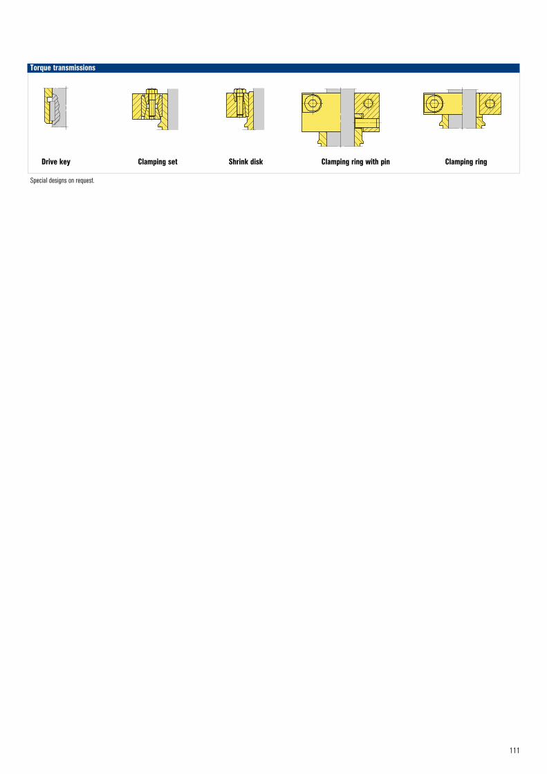
111
Torque transmissions
Drive key Clamping set Shrink disk Clamping ring with pin Clamping ring
Special designs on request.
Klem
mrin
g m
it St
ift ©
Eag
leBur
gman
n
Dreh
mom
entü
bertr
agun
g
Klem
mrin
g ©
Eag
leBur
gman
n
Dreh
mom
entü
bertr
agun
g
Torq
ue tr
ansm
ission
Clam
pings
et ©
Eag
leBur
gman
n
To
rque
tran
smiss
ion
Drive
key
© E
agleB
urgm
ann
T-Shrink disk II © EagleBurgmann
Variantwith bearing
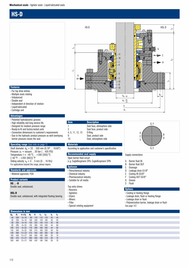
112
11
10
14
5
212913
AL 1
dw h8
d3 H8 e8
k
d1
G
C
B
L 2
l 4l 3
d2
HS–D © EagleBurgmannHS–LD © EagleBurgmann
l 3
HS-D
Mechanical seals • Agitator seals • Liquid-lubricated seals
Item Description1 Seal face, atmosphere side2 Seal face, product side4, 5, 11, 12, 13 O-Ring9 Seat, product side10 Seat, atmosphere side
HS … -DDouble seal, unbalanced.
HSL-DDouble seal, unbalanced, with integrated floating bearing.
Product variants
Dimensions in mmdw d1 n x d2 d3 k L1 L2 I3 I440 200 6 x 18 80 170 115 170 35 45 50 230 8 x 18 100 200 120 185 35 55 60 255 8 x 18 120 225 140 210 35 60 80 295 8 x 23 145 260 145 230 44 60
100 315 8 x 23 170 280 160 245 44 65 120 345 8 x 23 190 310 160 250 50 65 140 380 12 x 23 215 345 165 265 50 65 160 440 12 x 27 240 395 185 300 50 75 180 475 12 x 27 260 430 185 310 55 75 200 465 12 x 27 290 420 190 290 55 75
Options• Cooling or heating flange• Leakage drain, flush or heating flange• Leakage drain or flush• Polymerization barrier, leakage drain or flushSee page 107.
HS-D HSL-D
ACS
BD
G, E
G, F
HS-D © EagleBurgmannSupply connections
A Barrier fluid INB Barrier fluid OUTC DrainageD Leakage drain G1/8"E Cooling IN G3/8"F Cooling OUT G3/8"G GreaseS Flush
Features• For top drive entries• Multiple seals rotating• Unbalanced• Double seal• Independent of direction of rotation• Liquid-lubricated• Cartridge unit • Advantages• Patented hydrodynamic grooves• High reliability and long service life• Designed for medium pressure range• Ready-to-fit and factory-tested units• Connection dimensions to customer’s requirements• Due to the hydraulic product pressure as well overlaying barrier pressure closes the seal.
Operating range (see note on page 1)Shaft diameter: dw = 20 … 500 mm (0.79" … 19.69")Pressure: p1 = vacuum … 30 bar (… 435 PSI)Temperature: t = –40 °C … +200 (350) °C (–40 °F … +392 (662)) °FSliding velocity: vg = 0 … 5 m/s (0 … 16 ft/s)For applications beyond this range, please inquire.
Standards and approvals• Material approvals: FDA
MaterialsAccording to application and customer’s specification
Recommended seal supplyOpen barrier fluid circuite. g. EagleBurgmann SPA, EagleBurgmann SPN
Optionen• Petrochemical industry• Chemical industry• Pharmaceutical industry• Suitable for all media
Top entry drives:• Reactors• Agitators• Dryers• Mixers• Filter• Special rotating equipment
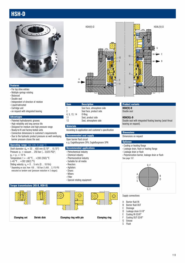
113
A
G
C
B121
2
11
13
4
5
14
DimensionsDimensions on request
Optionen• Cooling or heating flange• Leakage drain, flush or heating flange• Leakage drain or flush• Polymerization barrier, leakage drain or flushSee page 107.
HSH-D
Item Description1 Seal face, atmosphere side2 Seal face, product side4, 5, 13, 14 O-Ring11 Seat, product side12 Seat, atmosphere side
HSH(V)-DDouble seal
HSH(V)L-DDouble seal with integrated floating bearing (axial thrustbearing on request).
Product variants
HSH(V)-D HSHL(V)-D
ACS
BD
G, E
G, F
HS-D © EagleBurgmannSupply connections
A Barrier fluid INB Barrier fluid OUTC DrainageD Leakage drain G1/8"E Cooling IN G3/8"F Cooling OUT G3/8"G GreaseS Flush
Torque transmissions (HS-D, HSH-D)
Clamping set Shrink disk Clamping ring with pin Clamping ring
Klem
mrin
g m
it St
ift ©
Eag
leBur
gman
n
Dreh
mom
entü
bertr
agun
g
Klem
mrin
g ©
Eag
leBur
gman
n
Dreh
mom
entü
bertr
agun
g
Torq
ue tr
ansm
ission
Clam
pings
et ©
Eag
leBur
gman
n
T-Shrink disk II © EagleBurgmann
Features• For top drive entries• Multiple springs rotating• Balanced• Double seal• Independent of direction of rotation• Liquid-lubricated• Cartridge unit• on request with integrated bearing
• Advantages• Patented hydrodynamic grooves• High reliability and long service life• Designed for medium and high pressure range• Ready-to-fit and factory-tested units• Connection dimensions to customer’s requirements• Due to the hydraulic product pressure as well overlaying barrier pressure closes the seal.
Operating range (see note on page 1)Shaft diameter: dw = 20 … 400 mm (0.79" … 15.75")Pressure: p1 = vacuum … 250 bar (... 3,625 PSI)*, p3 = p1 + 10 %Temperature: t = –40 °C … +200 (350) °C (–40 °F … +392 (662) °F)Sliding velocity: vg = 0 … 5 m/s (0 … 16 ft/s)* Depending on size, from 100 … 150 bar (1,450 … 2,175 PSI
executed as tandem seal (pressure reduction in 2 stages).
MaterialsAccording to application and customer’s specification
Recommended seal supplyOpen barrier fluid circuite. g. EagleBurgmann SPA, EagleBurgmann SPN
Recommended applications• Petrochemical industry• Chemical industry• Pharmaceutical industry• Suitable for all media• Reactors• Agitators• Dryers• Mixers• Filter• Special rotating equipment
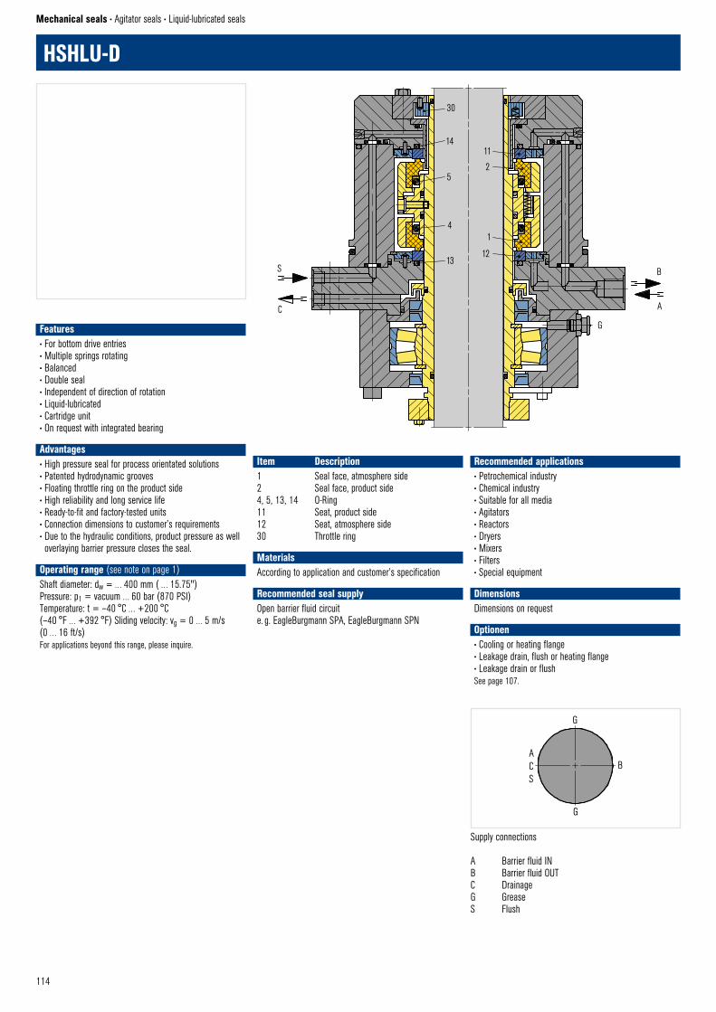
114
HSHLU-D
Mechanical seals • Agitator seals • Liquid-lubricated seals
Item Description1 Seal face, atmosphere side2 Seal face, product side4, 5, 13, 14 O-Ring11 Seat, product side12 Seat, atmosphere side30 Throttle ring
ACS
B
G
G
HSHLU-D © EagleBurgmannSupply connections
A Barrier fluid INB Barrier fluid OUTC DrainageG GreaseS Flush
S
C
B
A
HSHLU–D © EagleBurgmann
30
14
5
4
1312
1
2
11
G
Recommended applications• Petrochemical industry• Chemical industry• Suitable for all media• Agitators• Reactors• Dryers• Mixers• Filters• Special equipment
DimensionsDimensions on request
Optionen• Cooling or heating flange• Leakage drain, flush or heating flange• Leakage drain or flushSee page 107.
Features• For bottom drive entries• Multiple springs rotating• Balanced• Double seal• Independent of direction of rotation• Liquid-lubricated• Cartridge unit• On request with integrated bearing• Advantages• High pressure seal for process orientated solutions• Patented hydrodynamic grooves• Floating throttle ring on the product side• High reliability and long service life• Ready-to-fit and factory-tested units• Connection dimensions to customer’s requirements• Due to the hydraulic conditions, product pressure as well overlaying barrier pressure closes the seal.
Operating range (see note on page 1)Shaft diameter: dw = … 400 mm ( … 15.75")Pressure: p1 = vacuum … 60 bar (870 PSI)Temperature: t = –40 °C … +200 °C (–40 °F … +392 °F) Sliding velocity: vg = 0 … 5 m/s (0 … 16 ft/s)For applications beyond this range, please inquire.
MaterialsAccording to application and customer’s specification
Recommended seal supplyOpen barrier fluid circuite. g. EagleBurgmann SPA, EagleBurgmann SPN
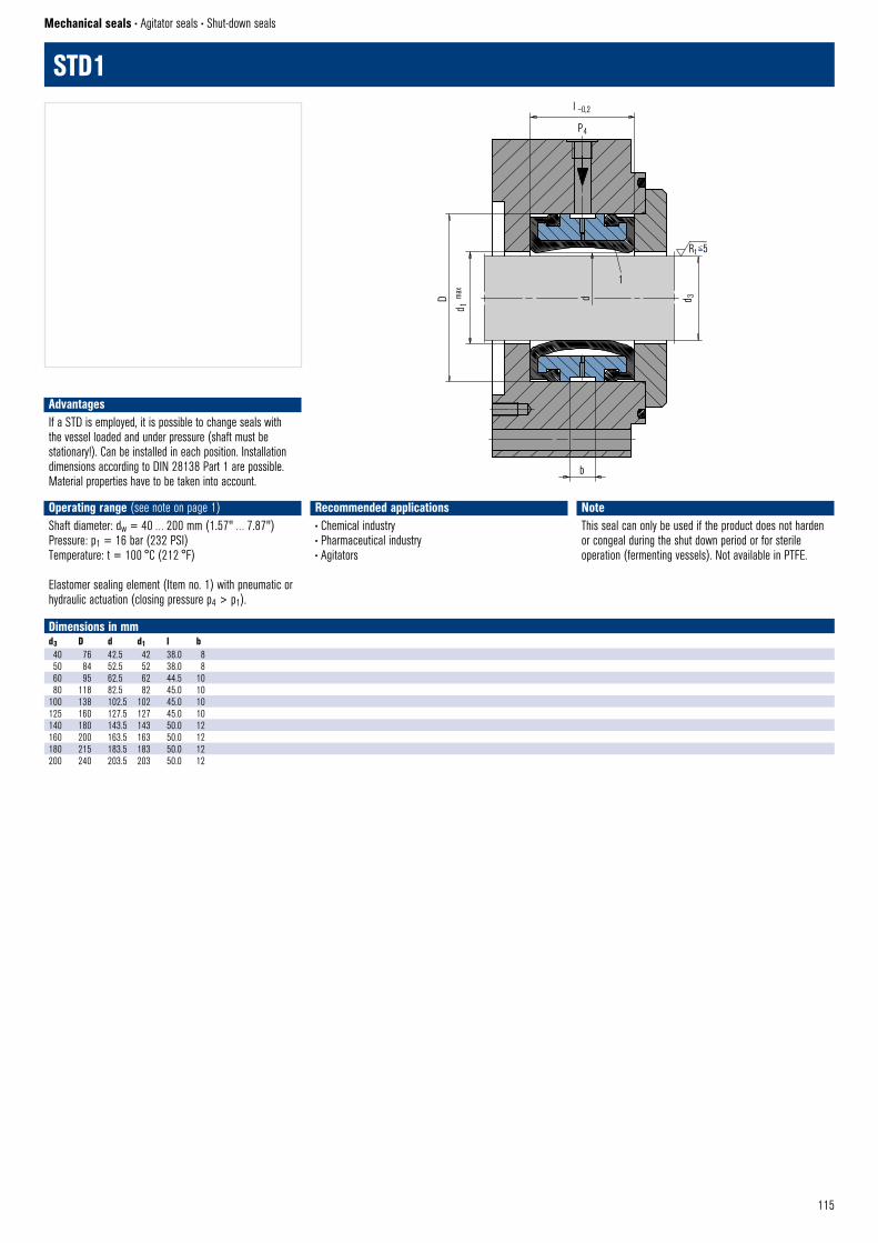
115
d 3d
Rt <5
l –0,2
P4
D
d 1 m
ax
1
b
STD1 © EagleBurgmann
STD1
Mechanical seals • Agitator seals • Shut-down seals
Dimensions in mmd3 D d d1 l b40 76 42.5 42 38.0 850 84 52.5 52 38.0 860 95 62.5 62 44.5 1080 118 82.5 82 45.0 10
100 138 102.5 102 45.0 10125 160 127.5 127 45.0 10140 180 143.5 143 50.0 12160 200 163.5 163 50.0 12180 215 183.5 183 50.0 12200 240 203.5 203 50.0 12
Recommended applications• Chemical industry• Pharmaceutical industry• Agitators
NoteThis seal can only be used if the product does not harden or congeal during the shut down period or for sterile operation (fermenting vessels). Not available in PTFE.
AdvantagesIf a STD is employed, it is possible to change seals with the vessel loaded and under pressure (shaft must be stationary!). Can be installed in each position. Installation dimensions according to DIN 28138 Part 1 are possible. Material properties have to be taken into account.
Operating range (see note on page 1)Shaft diameter: dw = 40 … 200 mm (1.57" … 7.87")Pressure: p1 = 16 bar (232 PSI)Temperature: t = 100 °C (212 °F)
Elastomer sealing element (Item no. 1) with pneumatic or hydraulic actuation (closing pressure p4 > p1).

116
DGS
Mechanical seals • Compressor seals • Gas-lubricated seals
Seals from the DGS series are the standard for medium pressures up to 120 bar (1,740 PSI). They have proven their suitability in thousands of applications worldwide. They are very rugged with a mature design concept. The advantage over the competition is hidden in the detail. For example, controlled dynamic sealing elements transmit the torque from the seat directly by friction and thus require no holes and resulting weakening of the material.
Features• Gas-lubricated• Unidirectional or bidirectional• Ready-to-fit cartridge unit• Single, Double, Tandem and Tandem with intermediate labyrinth available
• Separation seals as labyrinths, radial clearance seals or CobaSeal are optionally available
Advantages• Wear-free and contact-free operation• Self-cleaning 3D gas grooves• High gas film stiffness• Secure cupped retainer for seat• Available in various materials for optimized chemical resistance
• Proven, reliable and economical solution
Operating range (see note on page 1)Shaft diameter: ds1 = 29 … 264 mm (1.14" … 10.39")Pressure: p = 0 … 120 bar (1.740 PSI)Temperature: t = –20 °C … +200 °C (–4 °F … +392 °F)Sliding velocity: vg = 0.6 … 200 m/s (2 … 656 ft/s)
MaterialsSeal face: Silicon carbide with DLC coatingSeat: Silicon carbide with DLC coatingSecondary seals: FKMMetal parts: 1.4006 or other stainless steels
Other materials on request.
Available also with EagleBurgmann DiamondFace technology.
Standards and approvals• NACE
Recommended applications• Oil and gas industry• Refining technology• Petrochemical industry• Hydrocarbon gas• Ammonia• Nitrogen• Air• Centrifugal compressors• Turbo expanders• Blowers
DGS Single sealApplication: where leakage of the product into the atmosphere is not harmful, e.g. from air or nitrogen compressors or the axial cavity does not allow a tandem seal (e.g. geared compressors). This version allows process gas leakage to the corresponding flare / vent connection. Primary seal leakage is dissipated with the separation gas to the vent. The gas to be sealed must also be filtered and routed to the seal chamber via connection “A”. The resulting flow from the sealed space to the impeller side prevents contaminated / wet gas reaching the Dry Gas Seal on the process gas side, e.g. towards the labyrinth.
A Seal gas supplyB VentD Separation gas supply
Item Description1 Seal face, stationary 2 Seat, rotating 3 Thrust ring 4 Spring 5 Shaft sleeve and seat retainer 6 Intermediate sleeve and seat retainer 7, 8 Housing (size matched to installation space) 9 Separation seal (CSR) 10 Labyrinth 11 Intermediate labyrinth
10 5 2 1 3
4 7 9
D s1
D H
DGS–Single © EagleBurgmann
D 1
A B D
l1 lB
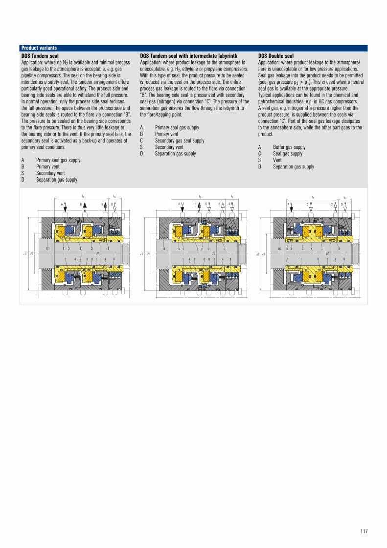
117
10 5 2 3 2
1 4 7 1
D s3
4 9
3
D 3 D H
l3
DGS Tandem mit Labyrinth © EagleBurgmann
lB
A B C S D
6 8
11 10 4 3 2 5 2 3
7 1 1 4 9
D s4
D 4 D H
l4 lB
A C S D
DGS double © EagleBurgmann
8
A B S D
l2 lB
D 2 D H
10 5 2 3 2 3
1 4 7 1 4 9
D s2
DGS Tandem © EagleBurgmann
6 8
Product variantsDGS Tandem sealApplication: where no N2 is available and minimal process gas leakage to the atmosphere is acceptable, e.g. gas pipeline compressors. The seal on the bearing side is intended as a safety seal. The tandem arrangement offers particularly good operational safety. The process side and bearing side seals are able to withstand the full pressure. In normal operation, only the process side seal reduces the full pressure. The space between the process side and bearing side seals is routed to the flare via connection “B”. The pressure to be sealed on the bearing side corresponds to the flare pressure. There is thus very little leakage to the bearing side or to the vent. If the primary seal fails, the secondary seal is activated as a back-up and operates at primary seal conditions.
A Primary seal gas supplyB Primary ventS Secondary ventD Separation gas supply
DGS Tandem seal with intermediate labyrinthApplication: where product leakage to the atmosphere is unacceptable, e.g. H2, ethylene or propylene compressors. With this type of seal, the product pressure to be sealed is reduced via the seal on the process side. The entire process gas leakage is routed to the flare via connection “B”. The bearing side seal is pressurized with secondary seal gas (nitrogen) via connection “C”. The pressure of the separation gas ensures the flow through the labyrinth to the flare/tapping point.
A Primary seal gas supplyB Primary ventC Secondary gas seal supplyS Secondary ventD Separation gas supply
DGS Double sealApplication: where product leakage to the atmosphere/flare is unacceptable or for low pressure applications. Seal gas leakage into the product needs to be permitted (seal gas pressure p3 > p1). This is used when a neutral seal gas is available at the appropriate pressure. Typical applications can be found in the chemical and petrochemical industries, e.g. in HC gas compressors. A seal gas, e.g. nitrogen at a pressure higher than the product pressure, is supplied between the seals via connection “C”. Part of the seal gas leakage dissipates to the atmosphere side, while the other part goes to the product.
A Buffer gas supplyC Seal gas supplyS VentD Separation gas supply
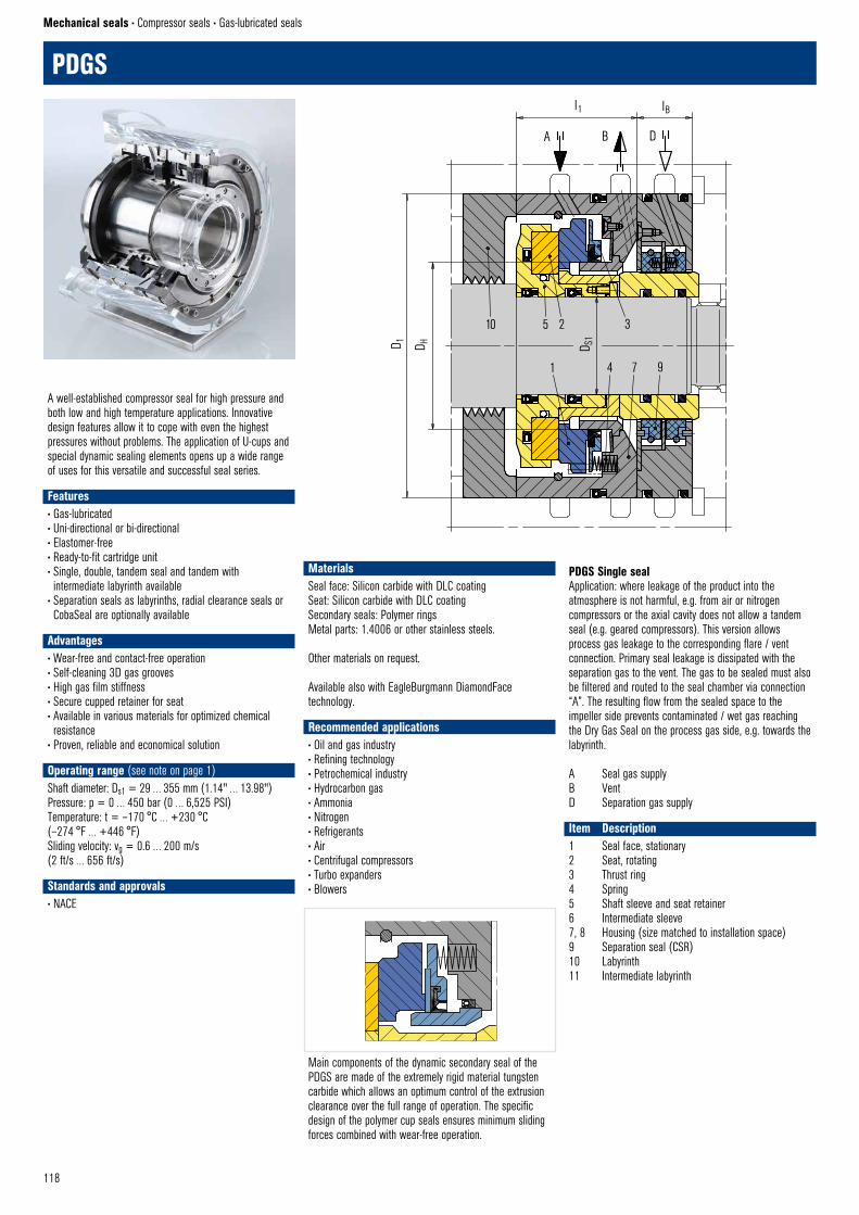
118
A B D
l1
D 1 D S1
PDGS–Single © EagleBurgmann
lB
D H
10 5 2 3
1 4 7 9
PDGS
Mechanical seals • Compressor seals • Gas-lubricated seals
A well-established compressor seal for high pressure and both low and high temperature applications. Innovative design features allow it to cope with even the highest pressures without problems. The application of U-cups and special dynamic sealing elements opens up a wide range of uses for this versatile and successful seal series.
Features• Gas-lubricated• Uni-directional or bi-directional• Elastomer-free• Ready-to-fit cartridge unit• Single, double, tandem seal and tandem with intermediate labyrinth available
• Separation seals as labyrinths, radial clearance seals or CobaSeal are optionally available
Advantages• Wear-free and contact-free operation• Self-cleaning 3D gas grooves• High gas film stiffness• Secure cupped retainer for seat• Available in various materials for optimized chemical resistance
• Proven, reliable and economical solution
Operating range (see note on page 1)Shaft diameter: Ds1 = 29 … 355 mm (1.14" … 13.98")Pressure: p = 0 … 450 bar (0 … 6,525 PSI)Temperature: t = –170 °C … +230 °C (–274 °F … +446 °F)Sliding velocity: vg = 0.6 … 200 m/s (2 ft/s … 656 ft/s)
Standards and approvals• NACE
PDGS Single sealApplication: where leakage of the product into the atmosphere is not harmful, e.g. from air or nitrogen compressors or the axial cavity does not allow a tandem seal (e.g. geared compressors). This version allows process gas leakage to the corresponding flare / vent connection. Primary seal leakage is dissipated with the separation gas to the vent. The gas to be sealed must also be filtered and routed to the seal chamber via connection “A”. The resulting flow from the sealed space to the impeller side prevents contaminated / wet gas reaching the Dry Gas Seal on the process gas side, e.g. towards the labyrinth.
A Seal gas supplyB VentD Separation gas supply
Item Description1 Seal face, stationary2 Seat, rotating3 Thrust ring4 Spring5 Shaft sleeve and seat retainer6 Intermediate sleeve 7, 8 Housing (size matched to installation space)9 Separation seal (CSR)10 Labyrinth11 Intermediate labyrinth
MaterialsSeal face: Silicon carbide with DLC coatingSeat: Silicon carbide with DLC coatingSecondary seals: Polymer ringsMetal parts: 1.4006 or other stainless steels.
Other materials on request.
Available also with EagleBurgmann DiamondFace technology.
Recommended applications• Oil and gas industry• Refining technology• Petrochemical industry• Hydrocarbon gas• Ammonia• Nitrogen• Refrigerants• Air• Centrifugal compressors• Turbo expanders• Blowers
PDGS Einzelheit © EagleBurgmann
Main components of the dynamic secondary seal of the PDGS are made of the extremely rigid material tungsten carbide which allows an optimum control of the extrusion clearance over the full range of operation. The specific design of the polymer cup seals ensures minimum sliding forces combined with wear-free operation.
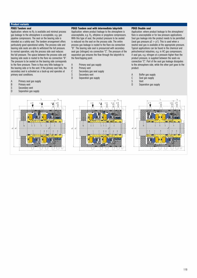
119
Product variants
PDGS–Tandem mit Labyrinth © EagleBurgmann
D H D S3
l3
A B C S D
5 2 3 2 410
3 91 7 1
lB
D 3
6 8
11
A C S D
l4 lB
D 4 D H
10 2 5 2 4
931
D s4
7 3 1 8
PDGS double © EagleBurgmann
A B S D
D 2 D S2
l2
PDGS –Tandem © EagleBurgmann
D H
10 5 2 3 2 4
1 7 1 3 9
lB
6 8
PDGS Tandem sealApplication: where no N2 is available and minimal process gas leakage to the atmosphere is acceptable, e.g. gas pipeline compressors. The seal on the bearing side is intended as a safety seal. The tandem arrangement offers particularly good operational safety. The process side and bearing side seals are able to withstand the full pressure. In normal operation, only the process side seal reduces the full pressure. The space between the process side and bearing side seals is routed to the flare via connection “B”. The pressure to be sealed on the bearing side corresponds to the flare pressure. There is thus very little leakage to the bearing side or to the vent. If the primary seal fails, the secondary seal is activated as a back-up and operates at primary seal conditions.
A Primary seal gas supplyB Primary ventS Secondary ventD Separation gas supply
PDGS Tandem seal with intermediate labyrinthApplication: where product leakage to the atmosphere is unacceptable, e.g. H2, ethylene or propylene compressors. With this type of seal, the product pressure to be sealed is reduced via the seal on the process side. The entire process gas leakage is routed to the flare via connection “B”. The bearing side seal is pressurized with secondary seal gas (nitrogen) via connection “C”. The pressure of the separation gas ensures the flow through the labyrinth to the flare/tapping point.
A Primary seal gas supplyB Primary ventC Secondary gas seal supplyS Secondary ventD Separation gas supply
PDGS Double sealApplication: where product leakage to the atmosphere/flare is unacceptable or for low pressure applications. Seal gas leakage into the product needs to be permitted (seal gas pressure p3 > p1). This is used when a neutral seal gas is available at the appropriate pressure. Typical applications can be found in the chemical and petrochemical industries, e.g. in HC gas compressors. A seal gas, e.g. nitrogen at a pressure higher than the product pressure, is supplied between the seals via connection “C”. Part of the seal gas leakage dissipates to the atmosphere side, while the other part goes to the product.
A Buffer gas supplyC Seal gas supplyS VentD Separation gas supply
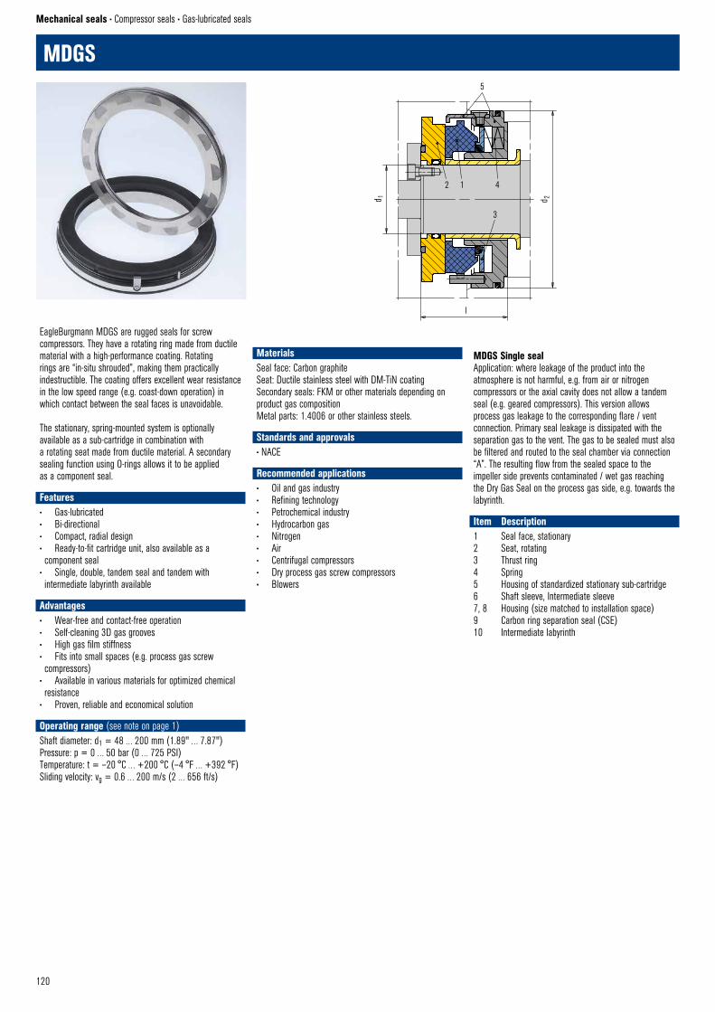
120
d 1 d 2
2 1 4
3
l
5
MDGS © EagleBurgmann
MDGS
Mechanical seals • Compressor seals • Gas-lubricated seals
EagleBurgmann MDGS are rugged seals for screw compressors. They have a rotating ring made from ductile material with a high-performance coating. Rotating rings are “in-situ shrouded”, making them practically indestructible. The coating offers excellent wear resistance in the low speed range (e.g. coast-down operation) in which contact between the seal faces is unavoidable.
The stationary, spring-mounted system is optionally available as a sub-cartridge in combination with a rotating seat made from ductile material. A secondary sealing function using O-rings allows it to be applied as a component seal.
Features• Gas-lubricated• Bi-directional• Compact, radial design• Ready-to-fit cartridge unit, also available as a component seal
• Single, double, tandem seal and tandem with intermediate labyrinth available
Advantages• Wear-free and contact-free operation• Self-cleaning 3D gas grooves• High gas film stiffness• Fits into small spaces (e.g. process gas screw compressors)
• Available in various materials for optimized chemical resistance
• Proven, reliable and economical solution
Operating range (see note on page 1)Shaft diameter: d1 = 48 … 200 mm (1.89" … 7.87")Pressure: p = 0 … 50 bar (0 … 725 PSI)Temperature: t = –20 °C … +200 °C (–4 °F … +392 °F)Sliding velocity: vg = 0.6 … 200 m/s (2 … 656 ft/s)
MDGS Single sealApplication: where leakage of the product into the atmosphere is not harmful, e.g. from air or nitrogen compressors or the axial cavity does not allow a tandem seal (e.g. geared compressors). This version allows process gas leakage to the corresponding flare / vent connection. Primary seal leakage is dissipated with the separation gas to the vent. The gas to be sealed must also be filtered and routed to the seal chamber via connection “A”. The resulting flow from the sealed space to the impeller side prevents contaminated / wet gas reaching the Dry Gas Seal on the process gas side, e.g. towards the labyrinth.
Item Description1 Seal face, stationary2 Seat, rotating3 Thrust ring4 Spring5 Housing of standardized stationary sub-cartridge6 Shaft sleeve, Intermediate sleeve7, 8 Housing (size matched to installation space)9 Carbon ring separation seal (CSE) 10 Intermediate labyrinth
MaterialsSeal face: Carbon graphiteSeat: Ductile stainless steel with DM-TiN coatingSecondary seals: FKM or other materials depending on product gas compositionMetal parts: 1.4006 or other stainless steels.
Standards and approvals• NACE
Recommended applications• Oil and gas industry• Refining technology• Petrochemical industry• Hydrocarbon gas• Nitrogen• Air• Centrifugal compressors• Dry process gas screw compressors• Blowers
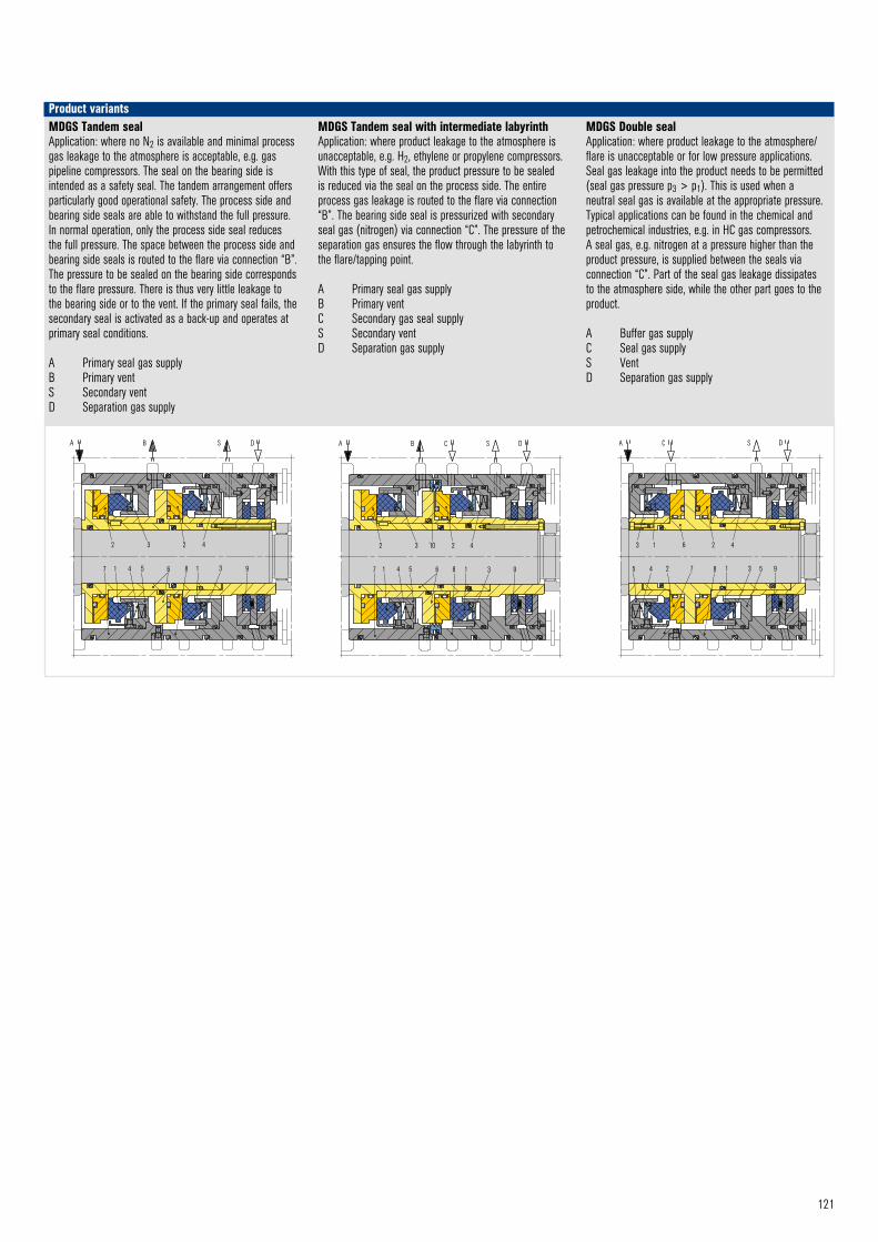
121
Product variants
A B S D
7
2 3 2 4
1 4 5 6 8 1 3 9
MDGS Tandem © EagleBurgmann
A B C S D
7
2 3 10 2 4
93186541
MDGS Tandem mit Labyrinth © EagleBurgmann
3 1 6 2 4
5 4 2 8 1 3 9
C S DA
MDGS Dual © EagleBurgmann
7 5
MDGS Tandem sealApplication: where no N2 is available and minimal process gas leakage to the atmosphere is acceptable, e.g. gas pipeline compressors. The seal on the bearing side is intended as a safety seal. The tandem arrangement offers particularly good operational safety. The process side and bearing side seals are able to withstand the full pressure. In normal operation, only the process side seal reduces the full pressure. The space between the process side and bearing side seals is routed to the flare via connection “B”. The pressure to be sealed on the bearing side corresponds to the flare pressure. There is thus very little leakage to the bearing side or to the vent. If the primary seal fails, the secondary seal is activated as a back-up and operates at primary seal conditions.
A Primary seal gas supplyB Primary ventS Secondary ventD Separation gas supply
MDGS Tandem seal with intermediate labyrinthApplication: where product leakage to the atmosphere is unacceptable, e.g. H2, ethylene or propylene compressors. With this type of seal, the product pressure to be sealed is reduced via the seal on the process side. The entire process gas leakage is routed to the flare via connection “B”. The bearing side seal is pressurized with secondary seal gas (nitrogen) via connection “C”. The pressure of the separation gas ensures the flow through the labyrinth to the flare/tapping point.
A Primary seal gas supplyB Primary ventC Secondary gas seal supplyS Secondary ventD Separation gas supply
MDGS Double sealApplication: where product leakage to the atmosphere/flare is unacceptable or for low pressure applications. Seal gas leakage into the product needs to be permitted (seal gas pressure p3 > p1). This is used when a neutral seal gas is available at the appropriate pressure. Typical applications can be found in the chemical and petrochemical industries, e.g. in HC gas compressors. A seal gas, e.g. nitrogen at a pressure higher than the product pressure, is supplied between the seals via connection “C”. Part of the seal gas leakage dissipates to the atmosphere side, while the other part goes to the product.
A Buffer gas supplyC Seal gas supplyS VentD Separation gas supply
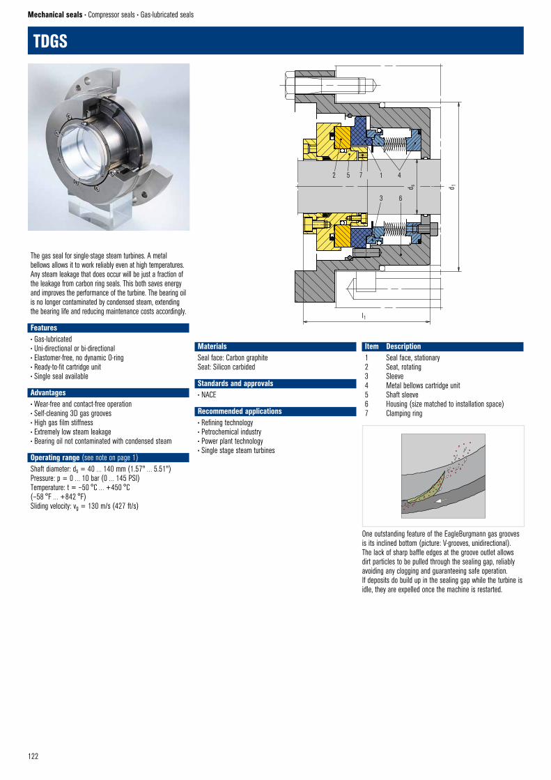
122
Mechanical seals • Compressor seals • Gas-lubricated seals
TDGS
TDGS © EagleBurgmann
One outstanding feature of the EagleBurgmann gas grooves is its inclined bottom (picture: V-grooves, unidirectional). The lack of sharp baffle edges at the groove outlet allows dirt particles to be pulled through the sealing gap, reliably avoiding any clogging and guaranteeing safe operation. If deposits do build up in the sealing gap while the turbine is idle, they are expelled once the machine is restarted.
2 5 1 4
3 6
l1
d s
TDGS © EagleBurgmann
d 1
7
The gas seal for single-stage steam turbines. A metal bellows allows it to work reliably even at high temperatures. Any steam leakage that does occur will be just a fraction of the leakage from carbon ring seals. This both saves energy and improves the performance of the turbine. The bearing oil is no longer contaminated by condensed steam, extending the bearing life and reducing maintenance costs accordingly.
Features• Gas-lubricated• Uni-directional or bi-directional• Elastomer-free, no dynamic O-ring• Ready-to-fit cartridge unit• Single seal available
Advantages• Wear-free and contact-free operation• Self-cleaning 3D gas grooves• High gas film stiffness• Extremely low steam leakage• Bearing oil not contaminated with condensed steam
Operating range (see note on page 1)Shaft diameter: ds = 40 … 140 mm (1.57" … 5.51")Pressure: p = 0 … 10 bar (0 … 145 PSI)Temperature: t = –50 °C … +450 °C (–58 °F … +842 °F)Sliding velocity: vg = 130 m/s (427 ft/s)
Item Description1 Seal face, stationary2 Seat, rotating3 Sleeve4 Metal bellows cartridge unit5 Shaft sleeve6 Housing (size matched to installation space)7 Clamping ring
MaterialsSeal face: Carbon graphiteSeat: Silicon carbided
Standards and approvals• NACE
Recommended applications• Refining technology• Petrochemical industry• Power plant technology• Single stage steam turbines
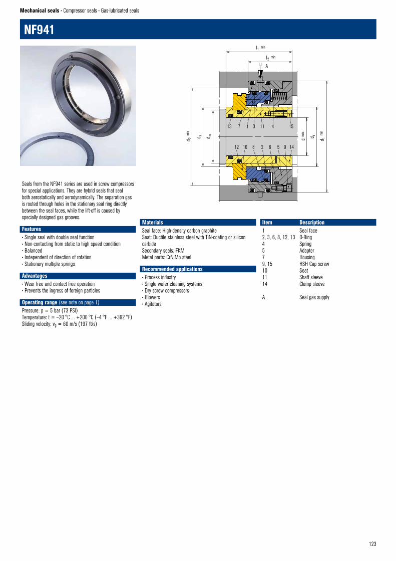
123
NF941
Mechanical seals • Compressor seals • Gas-lubricated seals
13 7 1 3 11 15
14956281012
4
l1 min
l2 min
d 2 m
in
d s
d m d 1 m
in
d s
d ma
x
NF941 © EagleBurgmann
A
Seals from the NF941 series are used in screw compressors for special applications. They are hybrid seals that seal both aerostatically and aerodynamically. The separation gas is routed through holes in the stationary seal ring directly between the seal faces, while the lift-off is caused by specially designed gas grooves.
Features• Single seal with double seal function• Non-contacting from static to high speed condition• Balanced• Independent of direction of rotation• Stationary multiple springs
Advantages• Wear-free and contact-free operation• Prevents the ingress of foreign particles
Operating range (see note on page 1)Pressure: p = 5 bar (73 PSI)Temperature: t = –20 °C … +200 °C (–4 °F … +392 °F)Sliding velocity: vg = 60 m/s (197 ft/s)
Item Description1 Seal face2, 3, 6, 8, 12, 13 O-Ring4 Spring5 Adapter7 Housing9, 15 HSH Cap screw10 Seat11 Shaft sleeve14 Clamp sleeve
A Seal gas supply
MaterialsSeal face: High-density carbon graphiteSeat: Ductile stainless steel with TiN-coating or silicon carbideSecondary seals: FKMMetal parts: CrNiMo steel
Recommended applications• Process industry• Single wafer cleaning systems• Dry screw compressors• Blowers• Agitators

124
WRS
Mechanical seals • Compressor seals • Oil-lubricated seals
3 2 1 2 3
13 6 7 6
WRS–double © EagleBurgmann
B
A
The WRS is an oil-lubricated seal that safely seals various types of compressors and organic media. With its rugged design, low life-cycle costs and long service life, the WRS can be found in thousands of applications. The design is optimized by using the finite element method and computational fluid dynamics..
Features• Oil-lubricated• Bi-directional• Externally pressurized• Ready-to-fit cartridge unit• Single, face bushing and double seal available• Suitable for high speed• Hydrodynamic grooves for increased operating capabilities and stabilized low leakage
Advantages• Low oil consumption• Rugged seat with bandage ensures reliable operation• Wear-free operation by use of lift-off-design• Does not open if oil pressure drops
Operating range (see note on page 1)Shaft diameter: 30 … 300 mm (1.18 " … 11.81")Pressure: p = … 50 bar (725 PSI)Gas temperature: t = -20 °C … +200 °C (-4 °F … +392 °F)Sliding velocity: vg = … 90 m/s (295 ft/s)Oil viscosity: ISO VG up to 68
Item Description1 Seat, rotating2 Seal face, stationary3 Face housing6 Spring7 Shaft sleeve13 Housing A Oil INB Oil OUT
MaterialsSeal face: Silicon carbide / CarbonSeat: Silicon carbideSecondary seals: FKM or other materials depending on product gas compositionMetal parts: 1.4006 or other stainless steels
Standards and approvals• NACE
Recommended applications• Oil and gas industry• Refining technology• Petrochemical industry• Refrigerants• Screw compressors• Centrifugal compressors• Geared compressors
Product variants
WRS Double seal
8 3 7 2 1
4 5 6
WRS20–E1 © EagleBurgmann
WRS10–ED1 © EagleBurgmann
B
A
WRS Single seal WRS Single seal with face bushing
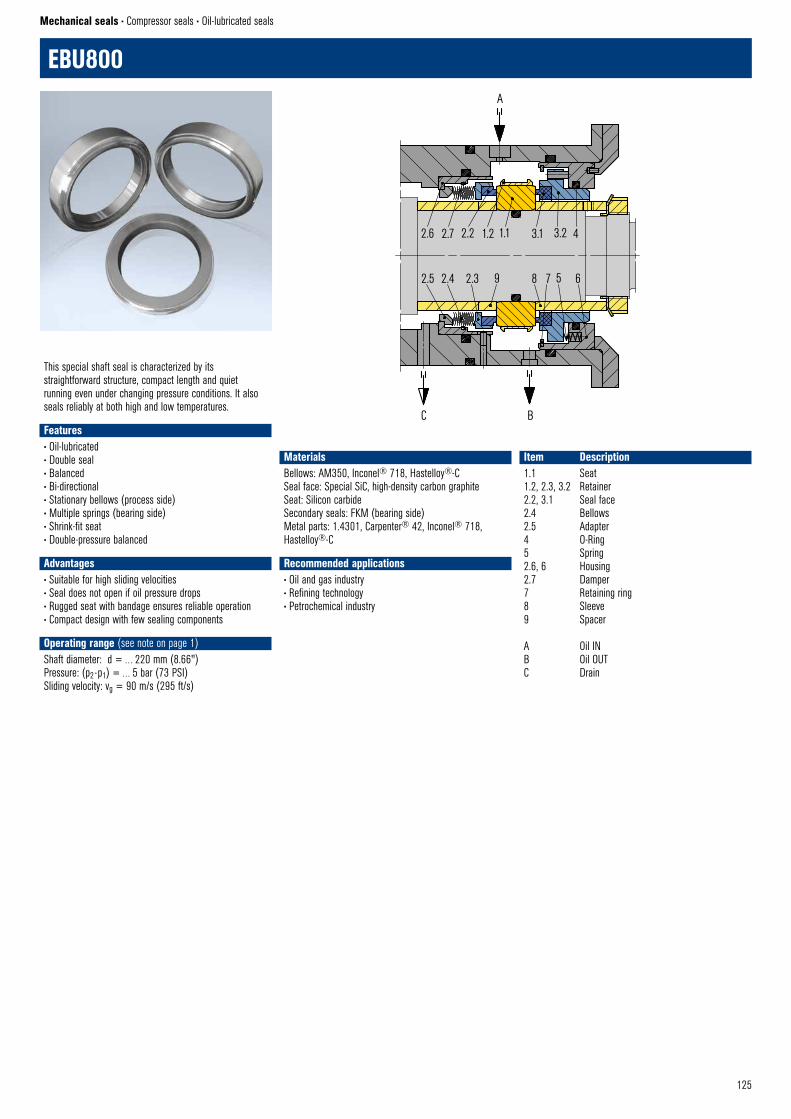
125
EBU800
Mechanical seals • Compressor seals • Oil-lubricated seals
This special shaft seal is characterized by its straightforward structure, compact length and quiet running even under changing pressure conditions. It also seals reliably at both high and low temperatures.
Features• Oil-lubricated• Double seal• Balanced• Bi-directional• Stationary bellows (process side)• Multiple springs (bearing side)• Shrink-fit seat• Double-pressure balanced
Advantages• Suitable for high sliding velocities• Seal does not open if oil pressure drops• Rugged seat with bandage ensures reliable operation• Compact design with few sealing components
Operating range (see note on page 1)Shaft diameter: d = … 220 mm (8.66")Pressure: (p2 - p1) = … 5 bar (73 PSI)Sliding velocity: vg = 90 m/s (295 ft/s)
Item Description1.1 Seat1.2, 2.3, 3.2 Retainer2.2, 3.1 Seal face2.4 Bellows2.5 Adapter4 O-Ring5 Spring2.6, 6 Housing2.7 Damper7 Retaining ring8 Sleeve9 Spacer A Oil INB Oil OUTC Drain
MaterialsBellows: AM350, Inconel® 718, Hastelloy®-CSeal face: Special SiC, high-density carbon graphiteSeat: Silicon carbideSecondary seals: FKM (bearing side)Metal parts: 1.4301, Carpenter® 42, Inconel® 718, Hastelloy®-C
Recommended applications• Oil and gas industry• Refining technology• Petrochemical industry
2.6 2.7 2.2 1.2 1.1
A
C B
3.1 3.2 4
2.5 2.4 2.3 9 8 7 5 6
EBU800 © EagleBurgmann
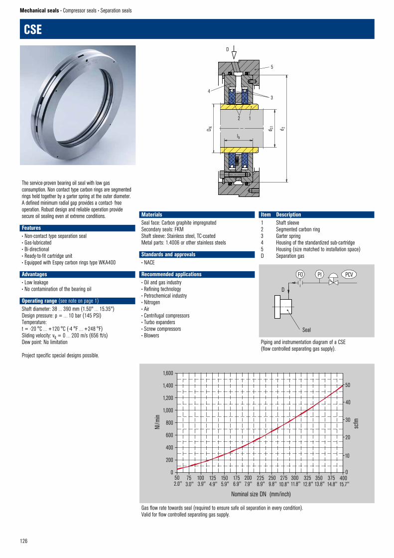
126
Mechanical seals • Compressor seals • Separation seals
The service-proven bearing oil seal with low gas consumption. Non contact type carbon rings are segmented rings held together by a garter spring at the outer diameter. A defined minimum radial gap provides a contact- free operation. Robust design and reliable operation provide secure oil sealing even at extreme conditions.
Features• Non-contact type separation seal• Gas-lubricated• Bi-directional• Ready-to-fit cartridge unit• Equipped with Espey carbon rings type WKA400
Advantages• Low leakage• No contamination of the bearing oil
Operating range (see note on page 1)Shaft diameter: 38 … 390 mm (1.50" … 15.35")Design pressure: p = … 10 bar (145 PSI)Temperature: t = -20 °C … +120 °C (-4 °F … +248 °F)Sliding velocity: vg = 0 … 200 m/s (656 ft/s)Dew point: No limitation
Project specific special designs possible.
Item Description1 Shaft sleeve2 Segmented carbon ring3 Garter spring4 Housing of the standardized sub-cartridge5 Housing (size matched to installation space)D Separation gas
MaterialsSeal face: Carbon graphite impregnatedSecondary seals: FKMShaft sleeve: Stainless steel, TC-coatedMetal parts: 1.4006 or other stainless steels
Standards and approvals• NACE
Recommended applications• Oil and gas industry• Refining technology• Petrochemical industry• Nitrogen• Air• Centrifugal compressors• Turbo expanders• Screw compressors• Blowers
CSED
5
3
2 1
lb
D N
CSE © EagleBurgmann
d S1
d 2
4
FO PI PCV
Seal
Schaltplan CSE © EagleBurgmann
D
Piping and instrumentation diagram of a CSE (flow controlled separating gas supply).
1,600
1,400
1,200
1,000
800
600
400
200
0
Nl/m
in
50 75 100 125 150 175 200 225 250 275 300 325 350 375 4002.0" 3.0" 3.9" 4.9" 5.9" 6.9" 7.9" 8.9" 9.8" 10.8" 11.8" 12.8" 13.8" 14.8" 15.7"
Nominal size DN (mm/inch)
50
40
30
20
scfm
10
0
GSE Gas consumtion © EagleBurgmann
Gas flow rate towards seal (required to ensure safe oil separation in every condition). Valid for flow controlled separating gas supply.
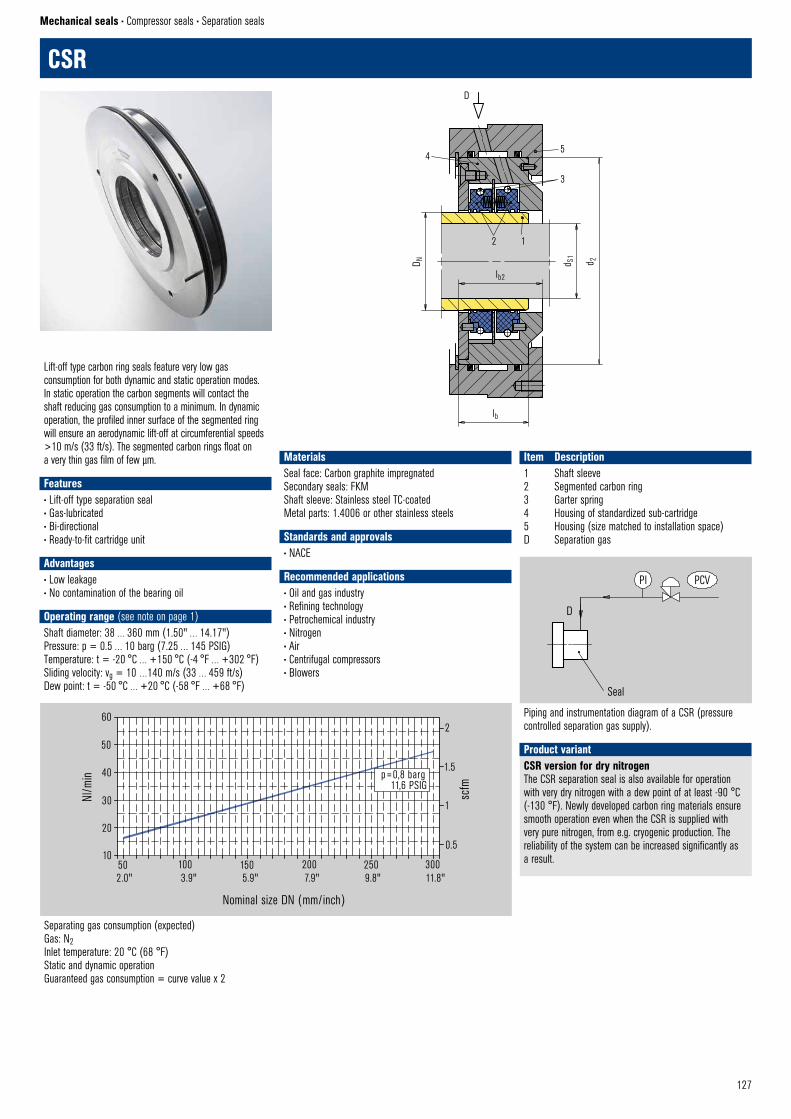
127
Mechanical seals • Compressor seals • Separation seals
CSRD
45
3
2 1
lb2
lb
CSR © EagleBurgmann
d S1
d 2
D N
CSR Gas consumtion© EagleBurgmann
Nominal size DN (mm/inch)
60
50
40
30
20
10
Nl/m
in
50 100 150 200 250 3002.0" 3.9" 5.9" 7.9" 9.8" 11.8"
2
1.5
1
0.5
scfm
p=0,8 barg11,6 PSIG
Piping and instrumentation diagram of a CSR (pressure controlled separation gas supply).
Separating gas consumption (expected)Gas: N2Inlet temperature: 20 °C (68 °F)Static and dynamic operationGuaranteed gas consumption = curve value x 2
D
Seal
PI PCV
PID CSR Schaltplan © EagleBurgmann
PCV
Lift-off type carbon ring seals feature very low gas consumption for both dynamic and static operation modes. In static operation the carbon segments will contact the shaft reducing gas consumption to a minimum. In dynamic operation, the profiled inner surface of the segmented ring will ensure an aerodynamic lift-off at circumferential speeds >10 m/s (33 ft/s). The segmented carbon rings float on a very thin gas film of few µm.
Features• Lift-off type separation seal• Gas-lubricated• Bi-directional• Ready-to-fit cartridge unit
Advantages• Low leakage• No contamination of the bearing oil
Operating range (see note on page 1)Shaft diameter: 38 … 360 mm (1.50" … 14.17")Pressure: p = 0.5 … 10 barg (7.25 … 145 PSIG)Temperature: t = -20 °C … +150 °C (-4 °F … +302 °F)Sliding velocity: vg = 10 …140 m/s (33 … 459 ft/s)Dew point: t = -50 °C … +20 °C (-58 °F … +68 °F)
Item Description1 Shaft sleeve2 Segmented carbon ring3 Garter spring4 Housing of standardized sub-cartridge5 Housing (size matched to installation space)D Separation gas
MaterialsSeal face: Carbon graphite impregnatedSecondary seals: FKMShaft sleeve: Stainless steel TC-coatedMetal parts: 1.4006 or other stainless steels
Standards and approvals• NACE
Recommended applications• Oil and gas industry• Refining technology• Petrochemical industry• Nitrogen• Air• Centrifugal compressors• Blowers
Product variantCSR version for dry nitrogenThe CSR separation seal is also available for operation with very dry nitrogen with a dew point of at least -90 °C (-130 °F). Newly developed carbon ring materials ensure smooth operation even when the CSR is supplied with very pure nitrogen, from e.g. cryogenic production. The reliability of the system can be increased significantly as a result.
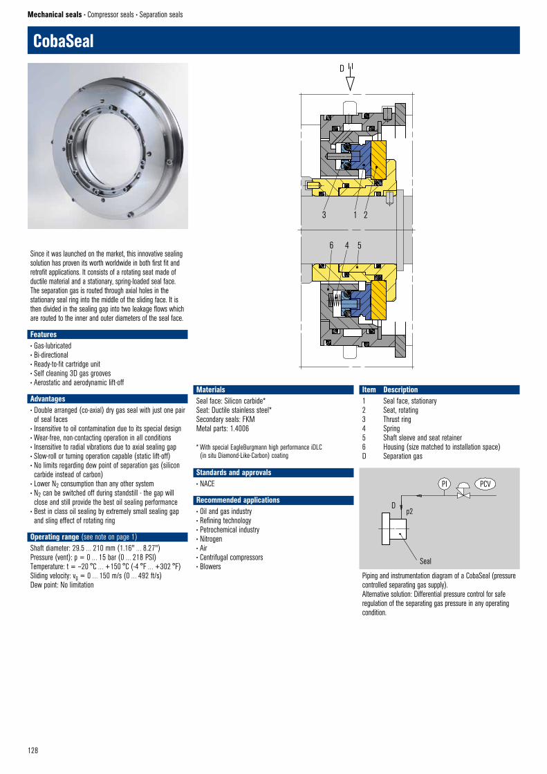
128
Mechanical seals • Compressor seals • Separation seals
CobaSeal
Piping and instrumentation diagram of a CobaSeal (pressure controlled separating gas supply).Alternative solution: Differential pressure control for safe regulation of the separating gas pressure in any operating condition.
D
Seal
PI PCV
PID CSR Schaltplan © EagleBurgmann
PCV
3 1 2
6 4 5
CobaSeal © EagleBurgmann
D
Since it was launched on the market, this innovative sealing solution has proven its worth worldwide in both first fit and retrofit applications. It consists of a rotating seat made of ductile material and a stationary, spring-loaded seal face. The separation gas is routed through axial holes in the stationary seal ring into the middle of the sliding face. It is then divided in the sealing gap into two leakage flows which are routed to the inner and outer diameters of the seal face.
Features• Gas-lubricated• Bi-directional• Ready-to-fit cartridge unit• Self cleaning 3D gas grooves• Aerostatic and aerodynamic lift-off
Advantages• Double arranged (co-axial) dry gas seal with just one pair of seal faces
• Insensitive to oil contamination due to its special design• Wear-free, non-contacting operation in all conditions• Insensitive to radial vibrations due to axial sealing gap• Slow-roll or turning operation capable (static lift-off)• No limits regarding dew point of separation gas (silicon carbide instead of carbon)
• Lower N2 consumption than any other system• N2 can be switched off during standstill - the gap will close and still provide the best oil sealing performance
• Best in class oil sealing by extremely small sealing gap and sling effect of rotating ring
Operating range (see note on page 1)Shaft diameter: 29.5 … 210 mm (1.16" … 8.27")Pressure (vent): p = 0 … 15 bar (0 … 218 PSI)Temperature: t = –20 °C … +150 °C (-4 °F … +302 °F)Sliding velocity: vg = 0 … 150 m/s (0 … 492 ft/s)Dew point: No limitation
Item Description1 Seal face, stationary2 Seat, rotating3 Thrust ring4 Spring5 Shaft sleeve and seat retainer6 Housing (size matched to installation space)D Separation gas
MaterialsSeal face: Silicon carbide*Seat: Ductile stainless steel*Secondary seals: FKMMetal parts: 1.4006
* With special EagleBurgmann high performance iDLC (in situ Diamond-Like-Carbon) coating
Standards and approvals• NACE
Recommended applications• Oil and gas industry• Refining technology• Petrochemical industry• Nitrogen• Air• Centrifugal compressors• Blowers
p2
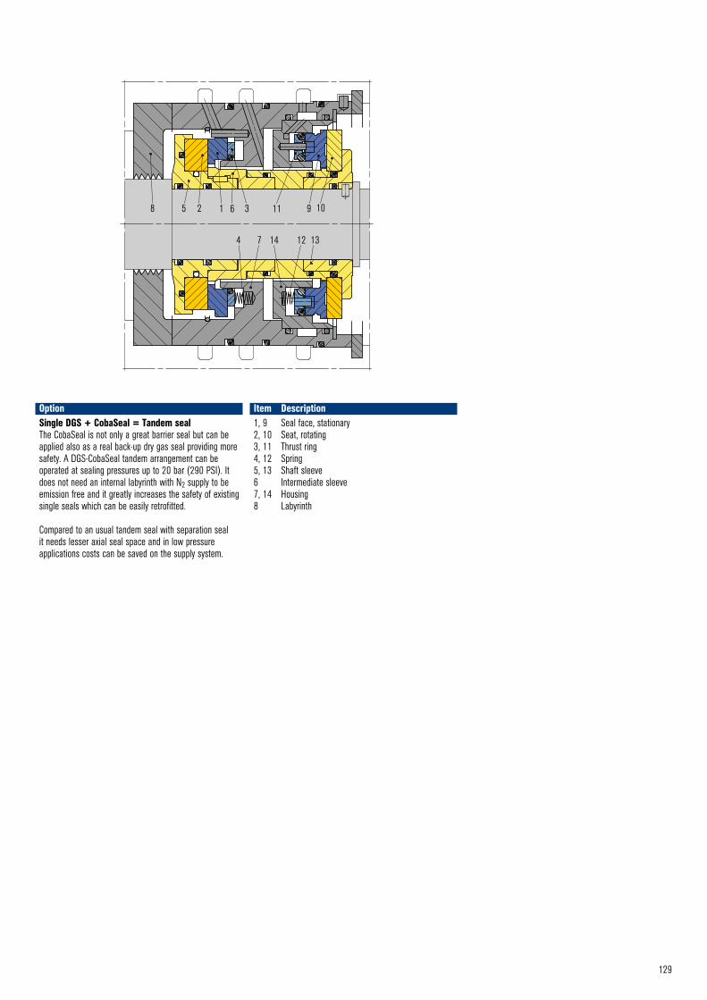
129
OptionSingle DGS + CobaSeal = Tandem seal The CobaSeal is not only a great barrier seal but can be applied also as a real back-up dry gas seal providing more safety. A DGS-CobaSeal tandem arrangement can be operated at sealing pressures up to 20 bar (290 PSI). It does not need an internal labyrinth with N2 supply to be emission free and it greatly increases the safety of existing single seals which can be easily retrofitted.
Compared to an usual tandem seal with separation seal it needs lesser axial seal space and in low pressure applications costs can be saved on the supply system.
Item Description1, 9 Seal face, stationary 2, 10 Seat, rotating 3, 11 Thrust ring 4, 12 Spring 5, 13 Shaft sleeve 6 Intermediate sleeve 7, 14 Housing 8 Labyrinth
8 5 2 1 6 3 11
4 7 14 12 13
9 10
A B D
DGS Single CobaSeal © EagleBurgmann
130130

131131
CouplingsMAK66. . . . . . . . . . . . . . . . . . . . . . . . . . . . . . . . . . 132MAK685 . . . . . . . . . . . . . . . . . . . . . . . . . . . . . . . . 134NMB High efficiency . . . . . . . . . . . . . . . . . . . . . . . 135SMAK . . . . . . . . . . . . . . . . . . . . . . . . . . . . . . . . . . . 136
BearingsLMF1 . . . . . . . . . . . . . . . . . . . . . . . . . . . . . . . . . . . 137
Uncompromising sealing technology for very demanding applications. Hermetically sealed magnetic couplings guarantee leakage-free and maintenance-free pumping and mixing. The media remains within closed system circulation loops.
Magnetic couplings 2
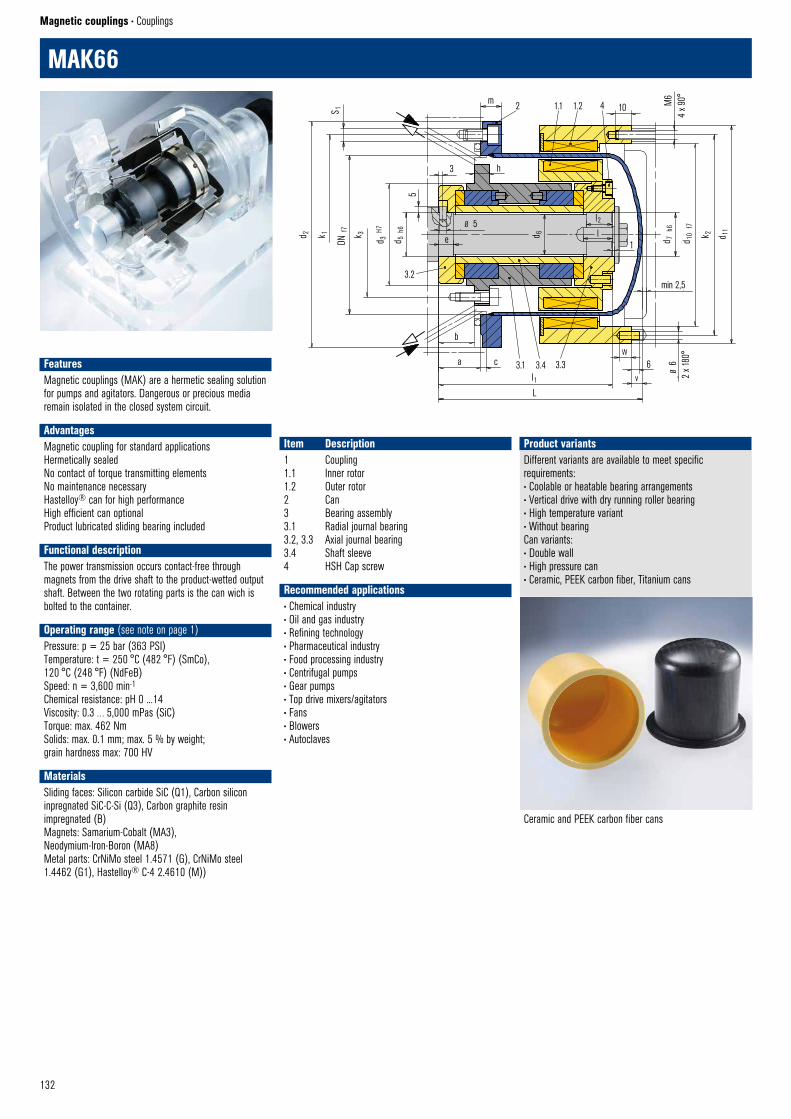
132
Magnetic couplings • Couplings
MAK66
FeaturesMagnetic couplings (MAK) are a hermetic sealing solution for pumps and agitators. Dangerous or precious media remain isolated in the closed system circuit.
AdvantagesMagnetic coupling for standard applicationsHermetically sealedNo contact of torque transmitting elementsNo maintenance necessaryHastelloy® can for high performanceHigh efficient can optionalProduct lubricated sliding bearing included
Functional description The power transmission occurs contact-free through magnets from the drive shaft to the product-wetted output shaft. Between the two rotating parts is the can wich is bolted to the container.
Operating range (see note on page 1)Pressure: p = 25 bar (363 PSI)Temperature: t = 250 °C (482 °F) (SmCo), 120 °C (248 °F) (NdFeB)Speed: n = 3,600 min-1
Chemical resistance: pH 0 ...14Viscosity: 0.3 … 5,000 mPas (SiC)Torque: max. 462 NmSolids: max. 0.1 mm; max. 5 % by weight; grain hardness max: 700 HV
Materials Sliding faces: Silicon carbide SiC (Q1), Carbon silicon inpregnated SiC-C-Si (Q3), Carbon graphite resin impregnated (B) Magnets: Samarium-Cobalt (MA3), Neodymium-Iron-Boron (MA8) Metal parts: CrNiMo steel 1.4571 (G), CrNiMo steel 1.4462 (G1), Hastelloy® C-4 2.4610 (M))
Recommended applications• Chemical industry• Oil and gas industry• Refining technology• Pharmaceutical industry• Food processing industry• Centrifugal pumps • Gear pumps • Top drive mixers/agitators • Fans • Blowers• Autoclaves
Item Description1 Coupling1.1 Inner rotor1.2 Outer rotor2 Can3 Bearing assembly3.1 Radial journal bearing3.2, 3.3 Axial journal bearing3.4 Shaft sleeve4 HSH Cap screw
Different variants are available to meet specific requirements:• Coolable or heatable bearing arrangements• Vertical drive with dry running roller bearing• High temperature variant• Without bearingCan variants:• Double wall• High pressure can• Ceramic, PEEK carbon fiber, Titanium cans
Product variants
Ceramic and PEEK carbon fiber cans
2 1.1 1.2 4 10m
S 1
d 2 k 1 k 3
DN f
7
d 3 H
7
d 5 h
6
5
3.2
e
Ø 5
d 6
l2l
1 d 7 h
6
d 10
f7
k 2 d 11
3 h
M6
4 x 9
0°
min 2,5
6W
v
Ø 6
2 x 1
80°
b
a c
L
l13.1 3.4 3.3
MAK66 © EagleBurgmann
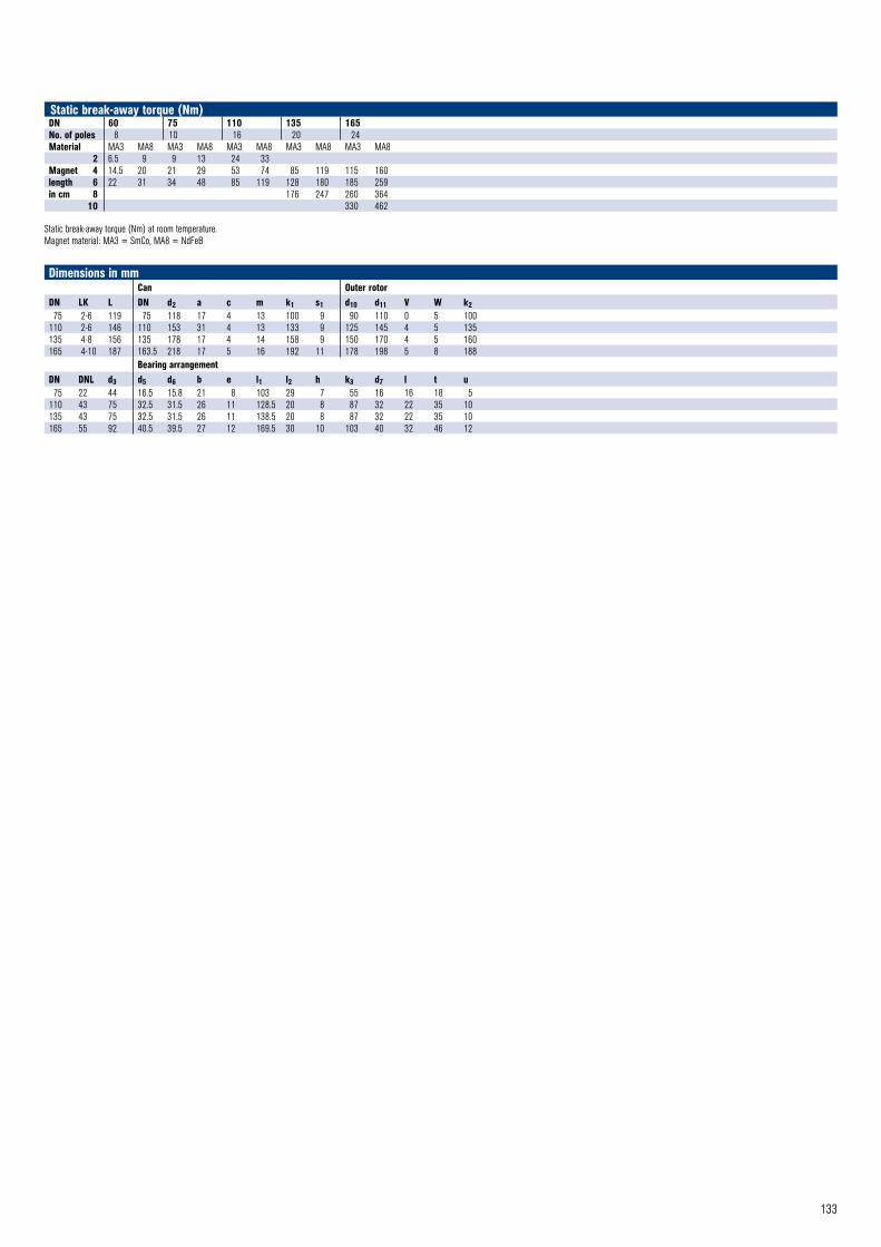
133
Dimensions in mmCan Outer rotor
DN LK L DN d2 a c m k1 s1 d10 d11 V W k275 2-6 119 75 118 17 4 13 100 9 90 110 0 5 100
110 2-6 146 110 153 31 4 13 133 9 125 145 4 5 135135 4-8 156 135 178 17 4 14 158 9 150 170 4 5 160165 4-10 187 163.5 218 17 5 16 192 11 178 198 5 8 188
Bearing arrangementDN DNL d3 d5 d6 b e l1 l2 h k3 d7 l t u75 22 44 16.5 15.8 21 8 103 29 7 55 16 16 18 5
110 43 75 32.5 31.5 26 11 128.5 20 8 87 32 22 35 10135 43 75 32.5 31.5 26 11 138.5 20 8 87 32 22 35 10165 55 92 40.5 39.5 27 12 169.5 30 10 103 40 32 46 12
DN 60 75 110 135 165No. of poles 8 10 16 20 24Material MA3 MA8 MA3 MA8 MA3 MA8 MA3 MA8 MA3 MA8 2 6.5 9 9 13 24 33Magnet 4 14.5 20 21 29 53 74 85 119 115 160length 6 22 31 34 48 85 119 128 180 185 259in cm 8 176 247 260 364 10 330 462
Static break-away torque (Nm) at room temperature.Magnet material: MA3 = SmCo, MA8 = NdFeB
Static break-away torque (Nm)
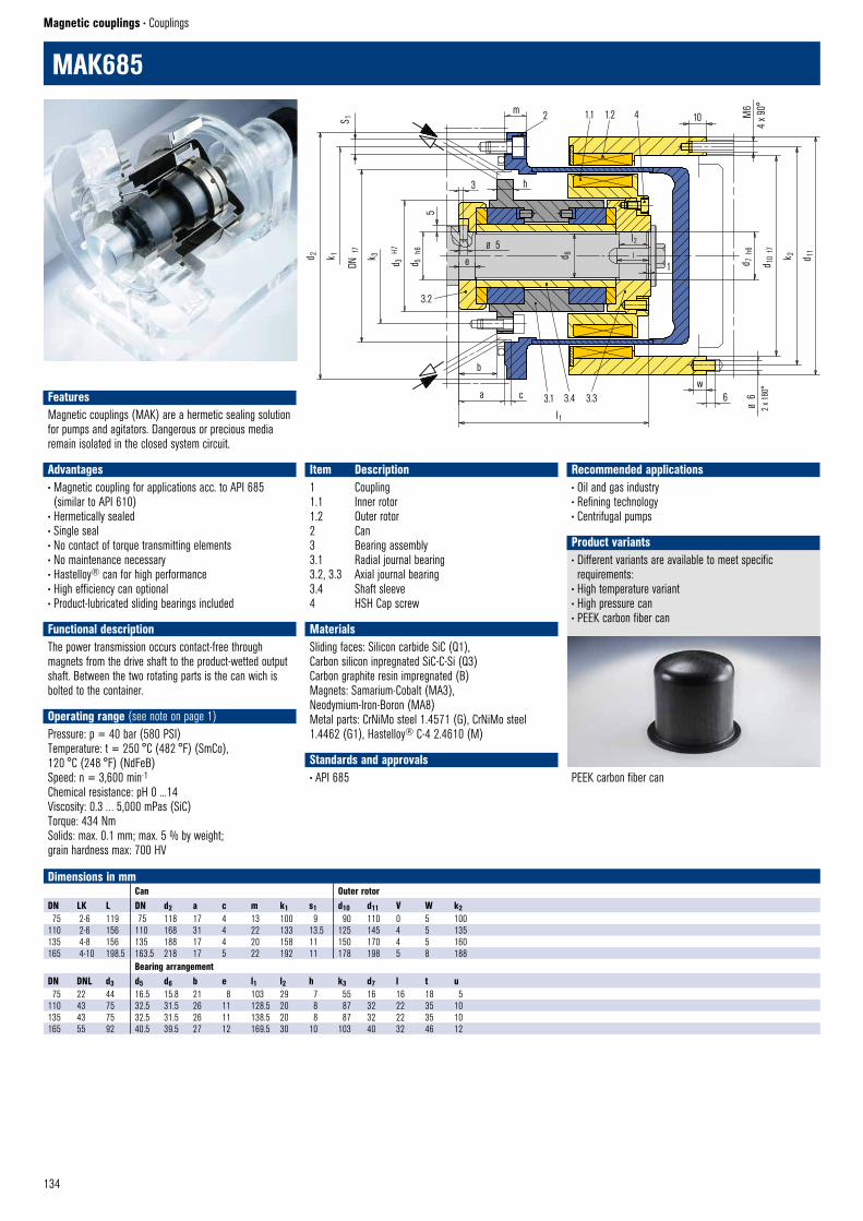
134
Magnetic couplings • Couplings
MAK685
Recommended applications• Oil and gas industry• Refining technology• Centrifugal pumps
• Different variants are available to meet specific requirements:
• High temperature variant• High pressure can• PEEK carbon fiber can
PEEK carbon fiber can
Product variants
Item Description1 Coupling1.1 Inner rotor1.2 Outer rotor2 Can3 Bearing assembly3.1 Radial journal bearing3.2, 3.3 Axial journal bearing3.4 Shaft sleeve4 HSH Cap screw
Dimensions in mmCan Outer rotor
DN LK L DN d2 a c m k1 s1 d10 d11 V W k275 2-6 119 75 118 17 4 13 100 9 90 110 0 5 100
110 2-6 156 110 168 31 4 22 133 13.5 125 145 4 5 135135 4-8 156 135 188 17 4 20 158 11 150 170 4 5 160165 4-10 198.5 163.5 218 17 5 22 192 11 178 198 5 8 188
Bearing arrangementDN DNL d3 d5 d6 b e l1 l2 h k3 d7 l t u75 22 44 16.5 15.8 21 8 103 29 7 55 16 16 18 5
110 43 75 32.5 31.5 26 11 128.5 20 8 87 32 22 35 10135 43 75 32.5 31.5 26 11 138.5 20 8 87 32 22 35 10165 55 92 40.5 39.5 27 12 169.5 30 10 103 40 32 46 12
1.1 1.2 4 102m
S 1
3 h
Ø 5
d 6
l2
l
1 d 7 h
6
d 10
f7 k 2 d 11
M6
4 x 9
0°
k 1d 2
DN f
7
k 3 d 3 H
7
d 5 h
6
5
3.2
e
b
a c 3.1 3.4 3.3
l1
MAK685 © EagleBurgmann
w6
Ø 6
2 x 1
80°
FeaturesMagnetic couplings (MAK) are a hermetic sealing solution for pumps and agitators. Dangerous or precious media remain isolated in the closed system circuit.
Advantages• Magnetic coupling for applications acc. to API 685 (similar to API 610)
• Hermetically sealed• Single seal• No contact of torque transmitting elements• No maintenance necessary• Hastelloy® can for high performance• High efficiency can optional• Product-lubricated sliding bearings included
Functional description The power transmission occurs contact-free through magnets from the drive shaft to the product-wetted output shaft. Between the two rotating parts is the can wich is bolted to the container.
Operating range (see note on page 1)Pressure: p = 40 bar (580 PSI)Temperature: t = 250 °C (482 °F) (SmCo), 120 °C (248 °F) (NdFeB)Speed: n = 3,600 min-1
Chemical resistance: pH 0 ...14Viscosity: 0.3 … 5,000 mPas (SiC)Torque: 434 NmSolids: max. 0.1 mm; max. 5 % by weight; grain hardness max: 700 HV
Materials Sliding faces: Silicon carbide SiC (Q1), Carbon silicon inpregnated SiC-C-Si (Q3) Carbon graphite resin impregnated (B) Magnets: Samarium-Cobalt (MA3), Neodymium-Iron-Boron (MA8) Metal parts: CrNiMo steel 1.4571 (G), CrNiMo steel 1.4462 (G1), Hastelloy® C-4 2.4610 (M)
Standards and approvals• API 685
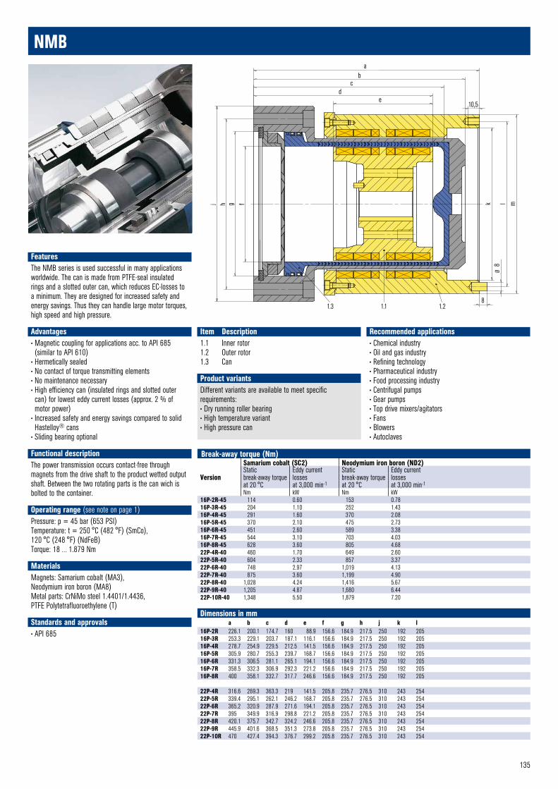
135
Recommended applications• Chemical industry• Oil and gas industry• Refining technology• Pharmaceutical industry• Food processing industry• Centrifugal pumps • Gear pumps • Top drive mixers/agitators • Fans • Blowers• Autoclaves
ab
cd
e10,5
j h g f k l m
Ø 8
81.3 1.1 1.2
NMB © EagleBurgmann
NMB
Item Description1.1 Inner rotor1.2 Outer rotor1.3 Can
Dimensions in mma b c d e f g h j k l
16P-2R 226.1 200.1 174.7 160 88.9 156.6 184.9 217.5 250 192 20516P-3R 253.3 229.1 203.7 187.1 116.1 156.6 184.9 217.5 250 192 20516P-4R 278.7 254.9 229.5 212.5 141.5 156.6 184.9 217.5 250 192 20516P-5R 305.9 280.7 255.3 239.7 168.7 156.6 184.9 217.5 250 192 20516P-6R 331.3 306.5 281.1 265.1 194.1 156.6 184.9 217.5 250 192 20516P-7R 358.5 332.3 306.9 292.3 221.2 156.6 184.9 217.5 250 192 20516P-8R 400 358.1 332.7 317.7 246.6 156.6 184.9 217.5 250 192 205
22P-4R 316.6 269.3 363.3 219 141.5 205.8 235.7 276.5 310 243 25422P-5R 339.4 295.1 262.1 246.2 168.7 205.8 235.7 276.5 310 243 25422P-6R 365.2 320.9 287.9 271.6 194.1 205.8 235.7 276.5 310 243 25422P-7R 395 349.9 316.9 298.8 221.2 205.8 235.7 276.5 310 243 25422P-8R 420.1 375.7 342.7 324.2 246.6 205.8 235.7 276.5 310 243 25422P-9R 445.9 401.6 368.5 351.3 273.8 205.8 235.7 276.5 310 243 25422P-10R 470 427.4 394.3 376.7 299.2 205.8 235.7 276.5 310 243 254
Break-away torque (Nm)
Version
Samarium cobalt (SC2) Neodymium iron boron (ND2)Staticbreak-away torque at 20 °C
Eddy currentlossesat 3,000 min-1
Staticbreak-away torque at 20 °C
Eddy currentlossesat 3,000 min-1
Nm kW Nm kW16P-2R-45 114 0.60 153 0.7816P-3R-45 204 1.10 252 1.4316P-4R-45 291 1.60 370 2.0816P-5R-45 370 2.10 475 2.7316P-6R-45 451 2.60 589 3.3816P-7R-45 544 3.10 703 4.0316P-8R-45 628 3.60 805 4.6822P-4R-40 460 1.70 649 2.6022P-5R-40 604 2.33 857 3.3722P-6R-40 748 2.97 1,019 4.1322P-7R-40 875 3.60 1,199 4.9022P-8R-40 1,028 4.24 1,416 5.6722P-9R-40 1,205 4.87 1,680 6.4422P-10R-40 1,348 5.50 1,879 7.20
Different variants are available to meet specific requirements:• Dry running roller bearing• High temperature variant• High pressure can
Product variants
FeaturesThe NMB series is used successful in many applications worldwide. The can is made from PTFE-seal insulated rings and a slotted outer can, which reduces EC-losses to a minimum. They are designed for increased safety and energy savings. Thus they can handle large motor torques, high speed and high pressure.
Advantages• Magnetic coupling for applications acc. to API 685 (similar to API 610)
• Hermetically sealed• No contact of torque transmitting elements• No maintenance necessary• High efficiency can (insulated rings and slotted outer can) for lowest eddy current losses (approx. 2 % of motor power)
• Increased safety and energy savings compared to solid Hastelloy® cans
• Sliding bearing optional
Functional description The power transmission occurs contact-free through magnets from the drive shaft to the product wetted output shaft. Between the two rotating parts is the can wich is bolted to the container.
Operating range (see note on page 1)Pressure: p = 45 bar (653 PSI)Temperature: t = 250 °C (482 °F) (SmCo), 120 °C (248 °F) (NdFeB)Torque: 18 … 1.879 Nm
MaterialsMagnets: Samarium cobalt (MA3), Neodymium iron boron (MA8)Metal parts: CrNiMo steel 1.4401/1.4436, PTFE Polytetrafluoroethylene (T)
Standards and approvals• API 685
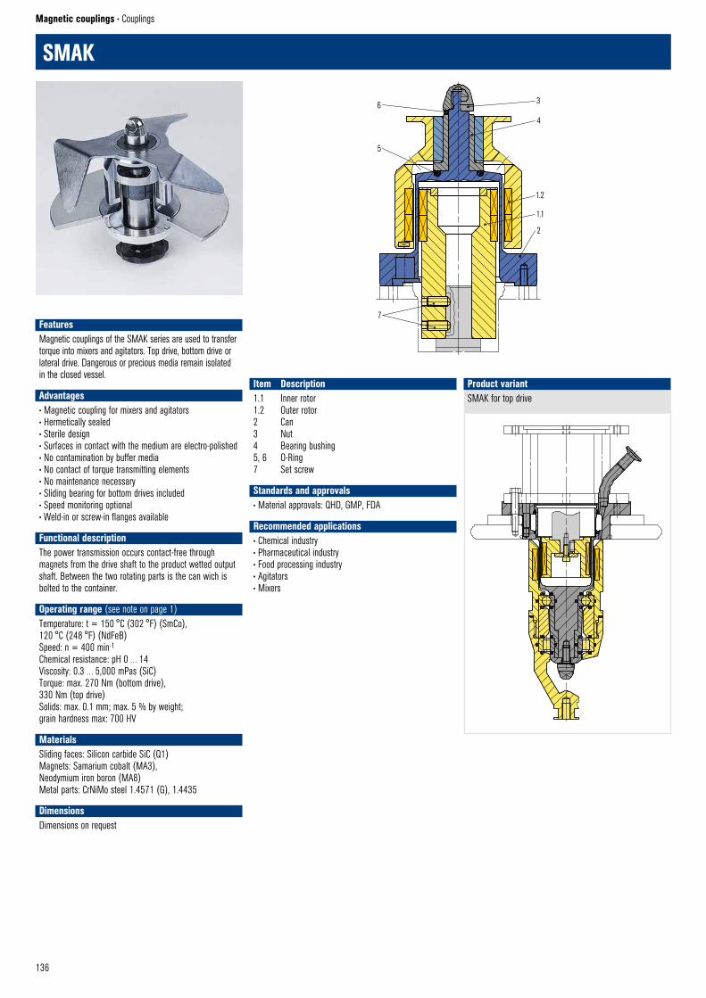
136
Magnetic couplings • Couplings
1.2
1.1
2
7
6
5
3
4
SMAK © EagleBurgmann
SMAK
Item Description1.1 Inner rotor1.2 Outer rotor2 Can3 Nut4 Bearing bushing5, 6 O-Ring7 Set screw
SMAK for top driveProduct variant
SMAK © EagleBurgmann
FeaturesMagnetic couplings of the SMAK series are used to transfer torque into mixers and agitators. Top drive, bottom drive or lateral drive. Dangerous or precious media remain isolated in the closed vessel.
Advantages• Magnetic coupling for mixers and agitators• Hermetically sealed• Sterile design• Surfaces in contact with the medium are electro-polished• No contamination by buffer media• No contact of torque transmitting elements• No maintenance necessary• Sliding bearing for bottom drives included• Speed monitoring optional• Weld-in or screw-in flanges available
Functional description The power transmission occurs contact-free through magnets from the drive shaft to the product wetted output shaft. Between the two rotating parts is the can wich is bolted to the container.
Operating range (see note on page 1)Temperature: t = 150 °C (302 °F) (SmCo), 120 °C (248 °F) (NdFeB)Speed: n = 400 min-1
Chemical resistance: pH 0 … 14Viscosity: 0.3 … 5,000 mPas (SiC)Torque: max. 270 Nm (bottom drive), 330 Nm (top drive)Solids: max. 0.1 mm; max. 5 % by weight; grain hardness max: 700 HV
MaterialsSliding faces: Silicon carbide SiC (Q1) Magnets: Samarium cobalt (MA3), Neodymium iron boron (MA8)Metal parts: CrNiMo steel 1.4571 (G), 1.4435
DimensionsDimensions on request
Standards and approvals• Material approvals: QHD, GMP, FDA
Recommended applications• Chemical industry• Pharmaceutical industry• Food processing industry• Agitators• Mixers
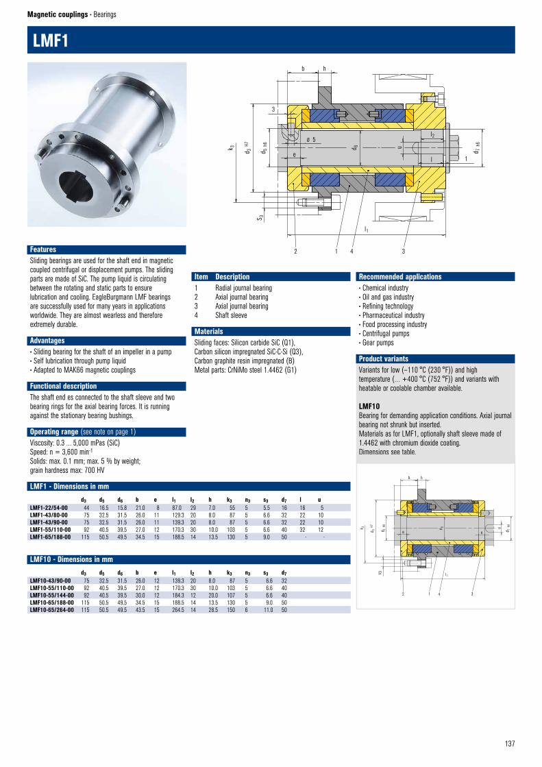
137
Magnetic couplings • Bearings
b h
3
k 3 d 3 H7
d 5 h
6
e
Ø 5
d 6 u
l2
l
l1
S 3
LMF1 © EagleBurgmann
2 1 4 3
1
d 7 h
6
LMF1
Item Description1 Radial journal bearing2 Axial journal bearing3 Axial journal bearing4 Shaft sleeve
LMF1 - Dimensions in mmd3 d5 d6 b e l1 l2 h k3 n3 s3 d7 l u
LMF1-22/54-00 44 16.5 15.8 21.0 8 87.0 29 7.0 55 5 5.5 16 16 5LMF1-43/80-00 75 32.5 31.5 26.0 11 129.3 20 8.0 87 5 6.6 32 22 10LMF1-43/90-00 75 32.5 31.5 26.0 11 139.3 20 8.0 87 5 6.6 32 22 10LMF1-55/110-00 92 40.5 39.5 27.0 12 170.3 30 10.0 103 5 6.6 40 32 12LMF1-65/188-00 115 50.5 49.5 34.5 15 188.5 14 13.5 130 5 9.0 50 - -
LMF10 - Dimensions in mmd3 d5 d6 b e l1 l2 h k3 n3 s3 d7
LMF10-43/90-00 75 32.5 31.5 26.0 12 139.3 20 8.0 87 5 6.6 32LMF10-55/110-00 92 40.5 39.5 27.0 12 170.3 30 10.0 103 5 6.6 40LMF10-55/144-00 92 40.5 39.5 30.0 12 184.3 12 20.0 107 5 6.6 40LMF10-65/188-00 115 50.5 49.5 34.5 15 188.5 14 13.5 130 5 9.0 50LMF10-65/264-00 115 50.5 49.5 43.5 15 264.5 14 28.5 150 6 11.0 50
Variants for low (–110 °C (230 °F)) and hightemperature (… +400 °C (752 °F)) and variants withheatable or coolable chamber available.
LMF10Bearing for demanding application conditions. Axial journal bearing not shrunk but inserted.Materials as for LMF1, optionally shaft sleeve made of 1.4462 with chromium dioxide coating.Dimensions see table.
Product variants
b h
k 3
d 3 H7
d 5 h
6
e
d 6
e
u
d 7 h
6
s 3 l 1
2 1 4 3
LMF10 © EagleBurgmann
FeaturesSliding bearings are used for the shaft end in magnetic coupled centrifugal or displacement pumps. The sliding parts are made of SiC. The pump liquid is circulating between the rotating and static parts to ensure lubrication and cooling. EagleBurgmann LMF bearings are successfully used for many years in applications worldwide. They are almost wearless and therefore extremely durable.
Advantages• Sliding bearing for the shaft of an impeller in a pump• Self lubrication through pump liquid• Adapted to MAK66 magnetic couplings
Functional description The shaft end es connected to the shaft sleeve and two bearing rings for the axial bearing forces. It is running against the stationary bearing bushings.
Operating range (see note on page 1)Viscosity: 0.3 … 5,000 mPas (SiC)Speed: n = 3,600 min-1
Solids: max. 0.1 mm; max. 5 % by weight; grain hardness max: 700 HV
MaterialsSliding faces: Silicon carbide SiC (Q1), Carbon silicon impregnated SiC-C-Si (Q3), Carbon graphite resin impregnated (B)Metal parts: CrNiMo steel 1.4462 (G1)
Recommended applications• Chemical industry• Oil and gas industry• Refining technology• Pharmaceutical industry• Food processing industry• Centrifugal pumps• Gear pumps
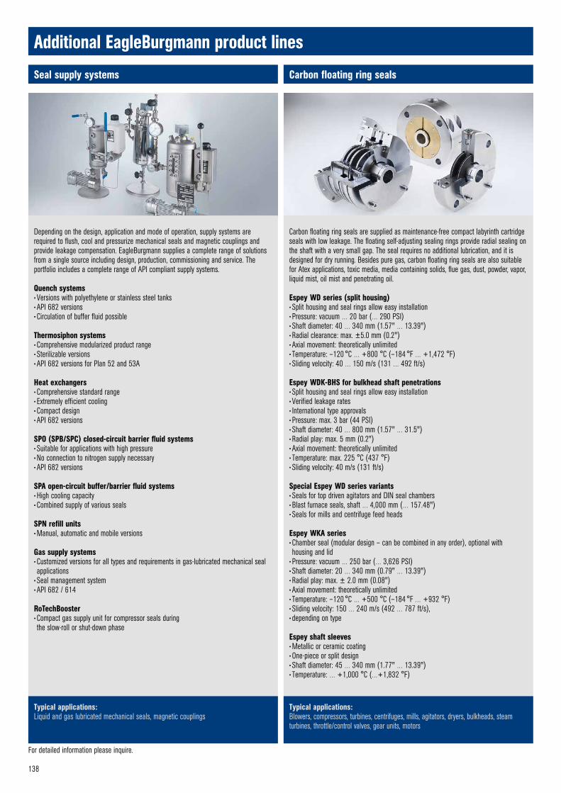
138
For detailed information please inquire.
Seal supply systems Carbon floating ring seals
Typical applications:Liquid and gas lubricated mechanical seals, magnetic couplings
Typical applications:Blowers, compressors, turbines, centrifuges, mills, agitators, dryers, bulkheads, steam turbines, throttle/control valves, gear units, motors
Additional EagleBurgmann product lines
Depending on the design, application and mode of operation, supply systems are required to flush, cool and pressurize mechanical seals and magnetic couplings and provide leakage compensation. EagleBurgmann supplies a complete range of solutions from a single source including design, production, commissioning and service. The portfolio includes a complete range of API compliant supply systems.
Quench systems• Versions with polyethylene or stainless steel tanks• API 682 versions• Circulation of buffer fluid possible
Thermosiphon systems• Comprehensive modularized product range• Sterilizable versions • API 682 versions for Plan 52 and 53A
Heat exchangers• Comprehensive standard range• Extremely efficient cooling• Compact design• API 682 versions
SPO (SPB/SPC) closed-circuit barrier fluid systems• Suitable for applications with high pressure• No connection to nitrogen supply necessary• API 682 versions
SPA open-circuit buffer/barrier fluid systems• High cooling capacity• Combined supply of various seals
SPN refill units• Manual, automatic and mobile versions
Gas supply systems• Customized versions for all types and requirements in gas-lubricated mechanical seal applications
• Seal management system• API 682 / 614
RoTechBooster • Compact gas supply unit for compressor seals during the slow-roll or shut-down phase
Carbon floating ring seals are supplied as maintenance-free compact labyrinth cartridge seals with low leakage. The floating self-adjusting sealing rings provide radial sealing on the shaft with a very small gap. The seal requires no additional lubrication, and it is designed for dry running. Besides pure gas, carbon floating ring seals are also suitable for Atex applications, toxic media, media containing solids, flue gas, dust, powder, vapor, liquid mist, oil mist and penetrating oil.
Espey WD series (split housing)• Split housing and seal rings allow easy installation• Pressure: vacuum … 20 bar (… 290 PSI)• Shaft diameter: 40 … 340 mm (1.57" … 13.39")• Radial clearance: max. ±5.0 mm (0.2")• Axial movement: theoretically unlimited• Temperature: –120 °C … +800 °C (–184 °F … +1,472 °F)• Sliding velocity: 40 … 150 m/s (131 … 492 ft/s)
Espey WDK-BHS for bulkhead shaft penetrations• Split housing and seal rings allow easy installation• Verified leakage rates• International type approvals• Pressure: max. 3 bar (44 PSI)• Shaft diameter: 40 … 800 mm (1.57" … 31.5")• Radial play: max. 5 mm (0.2")• Axial movement: theoretically unlimited• Temperature: max. 225 °C (437 °F)• Sliding velocity: 40 m/s (131 ft/s)
Special Espey WD series variants• Seals for top driven agitators and DIN seal chambers• Blast furnace seals, shaft … 4,000 mm (… 157.48")• Seals for mills and centrifuge feed heads
Espey WKA series• Chamber seal (modular design – can be combined in any order), optional with housing and lid
• Pressure: vacuum … 250 bar (… 3,626 PSI)• Shaft diameter: 20 … 340 mm (0.79" … 13.39")• Radial play: max. ± 2.0 mm (0.08")• Axial movement: theoretically unlimited• Temperature: –120 °C … +500 °C (–184 °F … +932 °F)• Sliding velocity: 150 … 240 m/s (492 … 787 ft/s), • depending on type
Espey shaft sleeves• Metallic or ceramic coating• One-piece or split design• Shaft diameter: 45 … 340 mm (1.77" … 13.39")• Temperature: … +1,000 °C (…+1,832 °F)

139
A cost effective and reliable method for sealing pump shafts, valve spindles and rotating shafts in process equipment. Manufactured from a range of material combinations – traditional and innovative – using state-of-the-art production techniques. Supplied in boxed lengths or pre-cut rings. Approvals/certification includes BAM, DVGW, FDA, API, ISO, TA-Luft. Fire-safe, low leakage, low emission and nuclear grades are available with full documentation and certification.
Rotatherm graphite ringsAn accepted industry-standard for valves and pumps in high pressure and high temperature service. Manufactured as moulded rings (with and without steel reinforcement) or special seals. Suits all industry applications including the power and nuclear industries. Approvals/certification includes: BAM, DVGW, API, ISO, TA-Luft.
BuraTAL Fugitive emission productsA comprehensive range of low leakage packing sets manufactured in graphite or our unique non-woven materials. All current fugitive emission standards are met with outstanding performance, low friction, ease of installation, and a long service life. Approvals/certification includes: API 622, ISO 15848, TA-Luft.
Burajet Injectable packingsThe Burajet Injectable packing system offers a wide range of injectable compounds for pumps, valves, and process equipment. An ideal product for the mining and paper & pulp industries. Approvals/Certification includes: FDA
Buraglas Glass packingsManufactured from non-ceramic materials and fibres, BuraGlas packings are suitable for sealing of vessels, coal mills, industrial furnaces, oven doors, hatches and covers. Produced in lengths in sizes up to 150 mm section. Approvals/Certification: Hydrolytische Klasse 1; DIN 12111.
Packing cartridgesPacking cartridges combine quick and easy installation with robust simple construction to provide minimum downtime and maximum reliability in critical process applications. Manufactured to individual requirements to fit into DIN/ASME standard equipment e.g. agitators. Cartridges can be supplied with live-loading and additional bellows containment for maximum environmental safety.
For detailed information please inquire.
Fibre gasket sheetsBurasil-Basic, -Universal and Buratherm N gasket sheets for service in low to medium pressure and temperature applications for process equipment and pipework in industry and for utility applications like gas and water supply.Approvals/certification includes: DVGW, KTW, HTB, WRAS, WRC, TA-Luft, BAM (Oxygen max. = 120 °C / 130 bar)
PTFE gasket sheets and tapesBurachem is a highly chemical resistant modified PTFE gasket material range offering varying properties of mechanical strength and chemical resistance depending upon application. Approvals/certification includes: DVGW, KTW, HTB, WRAS, WRC, BAM (Oxygen max. =120 °C / 130 bar), TA-Luft.Quick-Seal MultiTex tape is the latest development in the field of expanded PTFE sealing materials for in-place sealing of vessel and pipe flanges.
Graphite seals and tapesStatotherm Graphite gasket sheets, tapesSoft, flexible, graphite gasket sheets ideal for pump, valve, and equipment gaskets.Statotherm R Profile rings for static sealing in high temperature applications, e.g. in heat exchangers, valves or pumps.Statotherm V and V-Flex cover seals are used as self-sealing gaskets in high-pressure valves e.g. for power plants at high temperatures. Statotherm V-Flex is supplied by the meter.
Metal gasketsApprovals/certification include BAM, DVGW, TA-LuftSpiraltherm spiral wound gaskets. Available to suit all international flange standards and in a wide choice of materials.Corratherm corrugated gaskets are for heavy duty applications. Kammprofile serrated gaskets are for applications with high demands for operating safety and tightness. Buralloy metal jacketed gaskets are produced in a wide variety of different materials (in various combinations), in many styles for heat exchangers, pipe flanges, boilers, and process equipment.Buralloy ring type joints are available to suit all ASME and DIN flanges from stock. Sizes: 15 … 900 mm (0.5" … 36"); manufactured to ASME B16.20 and to API 6A.
Compression packings Gaskets
Typical applications:Pumps, agitators, mixers, kneaders, dryers, fans, blowers, filters, refiners, pulpers, mills, valves
Typical applications:Stationary machine parts, flanges, flange-like joints, bulkheads
Additional EagleBurgmann product lines

140
Expansion joints Special products
Typical applications:Engineered solutions designed to meet customer requirements
Typical applications:Air and flue gas ducts, pipelines, sewer systems
Additional EagleBurgmann product lines
Expansion joints are vital components in most industrial plants. They are installed as flexible connections in pipe and duct systems to take up or compensate for thermal expansion, vibration and misalignments. Advancements in processing and generating technologies are being combined with high demands for efficiency. This, along with a clear orientation towards environmental protection, puts high demands on expansion joint designs.
Customized expansion joints made of fabric or metal are the solution of choice.
Fabric expansion joints• Single and multilayer designs• Dimensions: according to customer specifications• Temperature -35 °C … +1,000 °C (-31 °F … + 1,832 °F) (higher temperature, on request)
• Pressure: +/-0.35 bar• Versions with wiremesh reinforcement• Versions with high chemical resistance• Versions with Nekal-tight design• Fabric expansion joint are available as units, including bolster and steel parts.
Metal expansion joints• Dimensions: Circular: DN40 and up. • Rectangular: According to customer specifications• Temperature: –198 °C ... +1,371 °C (–324 °F … + 2,500 °F)• Pressure: vacuum … 172 bar (… 2,500 PSI)• Materials: stainless steel, Incoloy® Inconel®, Hastelloy®, titanium, special materials• Single and universal designs• Metal expansion joints are available with for example tie rods, hinges, gimbals, refractory lining, elbow, pantograph.
Dimensions and pressure range depends on design, material selection, type of expansion joint and duct insulation.
For particular applications, innovative, customized solutions are the only answer. The supplier must have a wealth of in-depth expertise, many years of experience and above all the willingness and ability to translate ideas into solutions that work in practical application.
Contoured diaphragm couplingsFor demanding rotating equipment such as turbines and compressors in the oil and gas industries as well as petrochemicals, conventional and nuclear power generation, marine applications and the aerospace industry.
They are lightweight, easy to install and maintain, and demonstrate high reliability in stress analysis. Low bearing load, best dynamic balance repeatability and no fretting or wearing are advantages of the coupling. Uniquely shaped flexible elements in the metal diaphragms located at each end of the spacers attain optimum performance. Additional features:
• Couplings acc. to API 671 / ISO10441 or API 610 / ISO13709• Multi diaphragms, compensation for large misalignments• Low (reduced) moment• Electrically insulatet• Spark resistant materials• Tuned for rotor dynamics• Torque overload releasing device• Torque measuring system
Operating range: Max. torque: 2,700 kNm, max. speed: 100,000 min -1
High-grade metal bellows for specialized applications in the nuclear power, semi conductor and medical equipment industries, etc.
Dynamic and static sealing elements for the aerospace industry which meet extremely demanding quality requirements.
Stern tube and marine seals with various approvals and certifications, for marine outfitters and users.
Rotary kiln sealing systems as single and double seals in drying, calcination, combustion and pyrolysis applications.


Table of materials
Color code
Shaft
Housing, installation chamber
Elastomers
Stationary seal parts
Stationary seal faces
Rotary seal parts
Rotating seal faces
Material code Description1)EN 12756 EagleBurgmannFace materials (Item 1/2)Synthetic carbons
u A Buko 03 Carbon graphite antimony impregnated
u B Buko 1 Carbon graphite resin impregnated, approved for foodstuffs
B3 Buko 02 Carbon graphite resin impregnatedB5 Buko 34 Carbon, resin bonded
C Buko 22 Electrographite antimony impregnated
Metalsu E Bume 20 Cr steelG Bume 17 CrNiMo steelu S Bume 5 Special cast CrMo steelT41 Bube 281 1.4462 DLC-coatedCarbidesU = Tungsten carbidesu U1 Buka 1 brazed Tungsten carbide, Co-binderu U2 Buka 16 solid Tungsten carbide, Ni-binder
u U22 Buka 16 shrunk-in Tungsten carbide, Ni-binder
U3 Buka 15 solid Tungsten carbide, NiCrMo-binder
U37 Buka 15 shrunk-in Tungsten carbide, NiCrMo-binder
U7 Buka 17 solid Tungsten carbide, binder-freeQ = Silicon carbides
u Q1 Buka 22 solid SiC, silicon carbide, sintered pressureless
u Q12 Buka 22 shrunk-in SiC, sintered pressureless
u Q2 Buka 20 solid SiC-Si, reaction bonded
u Q22 Buka 20 shrunk-in SiC-Si, reaction bonded
Q3 Buka 30 solid SiC-C-Si, carbon silicon impr.
Q32 Buka 30 shrunk-in SiC-C-Si, carbon silicon impr.
Q6 Buka 32 solid SiC-C, SiC sintered pressureless with carbon
Q4 Buka 24 solid C-SiC, carbon surface silicatedQ19 Buka 221 SiC, DLC-coatedQ15 Buka 225 SiC, DiamondFaceMetal oxides (Ceramics)V Buke 5 Al-Oxide > 99 %V2 Buke 3 Al-Oxide > 96 %X Buke 8 Steatite (Magnesia silicate)Plasticsu Y1 Buku 2 PTFE glassfibre reinforcedY2 Buku 3 PTFE carbon reinforced
Material code Description1)EN 12756 EagleBurgmannSecondary seal components (Item 3)Elastomers, not wrappedB B Butyl rubber (IIR2))
u E E Ethylene propylene rubber (EPDM2)) e. g. Nordel®
K K Perfluorocarbon rubber (FFKM2)) e. g. Kalrez®, Chemraz®, Simriz®
N N Chloroprene rubber (CR2) e. g. Neopren®
u P P Nitrile-butadiene-rubber (NBR2)) e. g. Perbunan®
S S Silicone rubber (VMQ2)) e. g. Silopren®
u V V Fluorocarbon rubber (FKM2)) e. g. Viton®
X X4 Hydrogenated Nitrile-rubber (HNBR2))
X X5 Tetrafluoroethylene propylene rubber (FEPM2)) e. g. Aflas®, Fluoraz®
Elastomers, wrappedu M1 TTV FKM, double PTFE wrappedu M2 TTE EPDM, double PTFE wrappedM3 TTS VMQ, double PTFE wrappedM4 TTN CR, double PTFE wrappedM5 FEP FKM, FEP wrapped
M7 TTV/T FKM double PTFE wrapped/PTFE solid
Differing materialsU1 K/T Perfluorocarbon rubber/PTFENon-ElastomersG Statotherm Pure graphiteT T PTFE (Polytetrafluoroethylene)T2 T2 PTFE glass fiber reinforcedT3 T3 PTFE carbon reinforcedT12 T12 PTFE carbon-graphite reinforcedY1 Burasil-U Plastic fiber/Aramid
Material code Description1)EN 12756 EagleBurgmannSpring and construction materials (Item 4/5)Spring materialsu G 1.4571 CrNiMo steel
u M 2.4610 Hastelloy® C-4 Nickel-base alloy
Construction materialsD St C steelu E 1.4122 Cr steelF 1.4301 CrNi steelF 1.4308 CrNi cast steelF1 1.4313 Special cast CrNi steelu G 1.4401 CrNiMo steelu G 1.4571 CrNiMo steelG 1.4581 CrNiMo cast steelu G1 1.4462 CrNiMo steel – DuplexG2 1.4439 CrNiMo steelG3 1.4539 NiCrMo steelu G4 UNSS32760-Nor CrNiMoCu steel - SuperduplexM = Nickel-base alloyu M 2.4610 Hastelloy® C-4 M1 2.4617 Hastelloy® B-2 M3 2.4660 Carpenter® 20 Cb3 M4 2.4375 Monel® alloy K500 M5 2.4819 Hastelloy® C-276 M6 2.4668 Inconel® 718 T = Other materialsT1 1.4505 CrNiMoCuNb steelT2 3.7035 Pure titanium T3 2.4856 Inconel® 625 T4 1.3917 Carpenter® 42 T5 1.4876 Incoloy® 800
u Preferred materials 1) Standard following EN 12756, Dec. 2000 2) Abbreviations acc. to ISO 1629, Nov. 2004

Argentina · Australia · Austria · Belarus · Belgium · Bulgaria · Brazil · Canada · Chile · China · Colombia · Cyprus · Czech Republic · Denmark · Ecuador · Egypt · Estonia Finland · France · Germany · Great Britain · Greece · Hungary · India · Indonesia · Iraq · Israel · Italy · Japan · Jordan · Kazakhstan · Korea · Kuwait · Latvia · Libya · Lithuania Malaysia · Mauritius · Mexico · Morocco · Myanmar · Netherlands · New Zealand · Nigeria · Norway · Oman · Pakistan · Paraguay · Peru · Philippines · Poland · QatarRomania · Russia · Saudi Arabia · Singapore · Slovenia · Slovak Republic · South Africa · Spain · Sweden · Switzerland · Syria · Taiwan · Thailand · Trinidad and Tobago · Tunisia Turkey · Turkmenistan · Ukraine · United Arab Emirates · Uruguay · USA · Uzbekistan · Venezuela · Vietnam · www.eagleburgmann.com/world
EagleBurgmann is one of the internationally leading companies for industrial sealing technology. Our products are used everywhere where safety and reliability are important: in the oil and gas industry, refi ning technology, the petrochemical, chemical and pharmaceutical industries, food processing, power, water, mining, pulp & paper, aerospace and many other spheres. Every day, more than 6,000 employees contribute their ideas, solutions and commitment towards ensuring that customers all over the world can rely on our seals. Our modular TotalSealCare service underlines our strong customer orientation and offers tailor-made services for every application.4
TotalSealCare service modules
The modular seal service offered through TotalSealCare is as individual as are the demands of our customers. The range of services spans complete maintenance of all installed seals, through to stock management, as well as engineering, training and electronic data documentation.
Our TotalSealCare services consist of individual modules from which we assemble individualized service packages.
You can benefit from our many years of experience and expertise in all areas of seal technology, and our major store of practical knowledge.
7651
2
43
Consulting & engineering
After establishing and analyzing all of the seals in a system, we work out standardization concepts based on the as-is status. The results we are hoping for are to reduce the number of seal types, sizes and materials used, and to improve the key figures of the system. We advise you relating to codes of practice and statutory regulations, and indicate what actions need to be taken.
Maintenance
In the plant or in the service center, qualified fitters and technicians look after all the aspects of seal maintenance: installation, startup, servicing, conversion, overhaul and repair. We record and document functionally relevant data (fault causes, measures for repair, costs). This means it is possible to assess seal operating times and maintenance costs on a continuous basis, thereby defining measures for extending service intervals.
On-site service
Our on-site service includes the components of an overhaul service, conversions and service container. We deploy a service unit directly on your premises: equipped with the basic suite of seals or a stock of seals discussed with you in advance, and staffed by qualified personnel. On-site, our work includes producing the necessary gaskets, ensuring that the documentation is complete and advising our customers on selecting and installing seals. Our range of services is rounded off by complete conversions (e. g. acc. to TA-Luft).
Inventory management
Based on your individual requirements and the applicable quality regulations, we develop a concept for inventory management of complete seals and spare parts. Furthermore, we optimize stocking on site or in the EagleBurgmann service center. In this way, you can reduce your administration overhead and concentrate on your key operations.
Seminars & training
We offer an extensive range of continuing education programs in seal technology. For service and maintenance personnel, skilled staff and engineers from various branches of industry such as refining, chemicals, power generation, foodstuffs, paper and pharmaceuticals. Our range includes group seminars, individual training and seminars specifically tailored to your requirements. At our premises or at a location of your choice.
Technical analysis & support
A team of seal specialists is responsible for rectifying process malfunctions or “bad actors”. The latest methods such as thermography or data logging are used for diagnosing positions that are critical for the operation of the system and for working out measures to rectify them. In our research and development centers, we perform realistic tests on test rigs or in original pumps. The objective is to extend the MTBF and to increase system serviceability by individual and constructive solutions.
Service agreements
We offer our customers specific agreements that can be combined from the six service modules. Whether for individual seal systems, critical process elements, specific system areas or an extensive seal service for complete plants: the modular structure of our service makes it possible to satisfy individual requirements. With our tried-and-tested monitoring instrument, SEPRO, we can also record all data relevant for the seals for documentation and evaluation purposes.
TotalSealCare Service
Argentina · Australia · Austria · Belarus · Belgium · Bulgaria · Brazil · Canada · Chile · China · Colombia · Cyprus · Czech Republic · Denmark · Ecuador · Egypt · Estonia Finland · France · Germany · Great Britain · Greece · Hungary · India · Indonesia · Iraq · Israel · Italy · Japan · Jordan · Kazakhstan · Korea · Kuwait · Latvia · Libya · Lithuania Malaysia · Mauritius · Mexico · Morocco · Myanmar · Netherlands · New Zealand · Nigeria · Norway · Oman · Pakistan · Paraguay · Peru · Philippines · Poland · QatarRomania · Russia · Saudi Arabia · Singapore · Slovenia · Slovak Republic · South Africa · Spain · Sweden · Switzerland · Syria · Taiwan · Thailand · Trinidad and Tobago · Tunisia Turkey · Turkmenistan · Ukraine · United Arab Emirates · Uruguay · USA · Uzbekistan · Venezuela · Vietnam · www.eagleburgmann.com/world
EagleBurgmann is one of the internationally leading companies for industrial sealing technology. Our products are used everywhere where safety and reliability are important: in the oil and gas industry, refi ning technology, the petrochemical, chemical and pharmaceutical industries, food processing, power, water, mining, pulp & paper, aerospace and many other spheres. Every day, more than 6,000 employees contribute their ideas, solutions and commitment towards ensuring that customers all over the world can rely on our seals. Our modular TotalSealCare service underlines our strong customer orientation and offers tailor-made services for every application.
DMS_
MSE
/ E3
/ PD
F / 0
2.15
/ 9.7.
1 ©
Eag
leBur
gman
n Gro
up M
arke
ting,
Germ
any