pump mechanical seal - process · pump mechanical seal centrifugal, horizontal, lined cl seal-m...
TRANSCRIPT
Setting Innovative
Standards
M PUMPS PROCESS SRL Via dell’artigianato, 120
45015 Corbola (RO) – Italia Tel. +39 0426 346304 Fax + 39 0426 349126
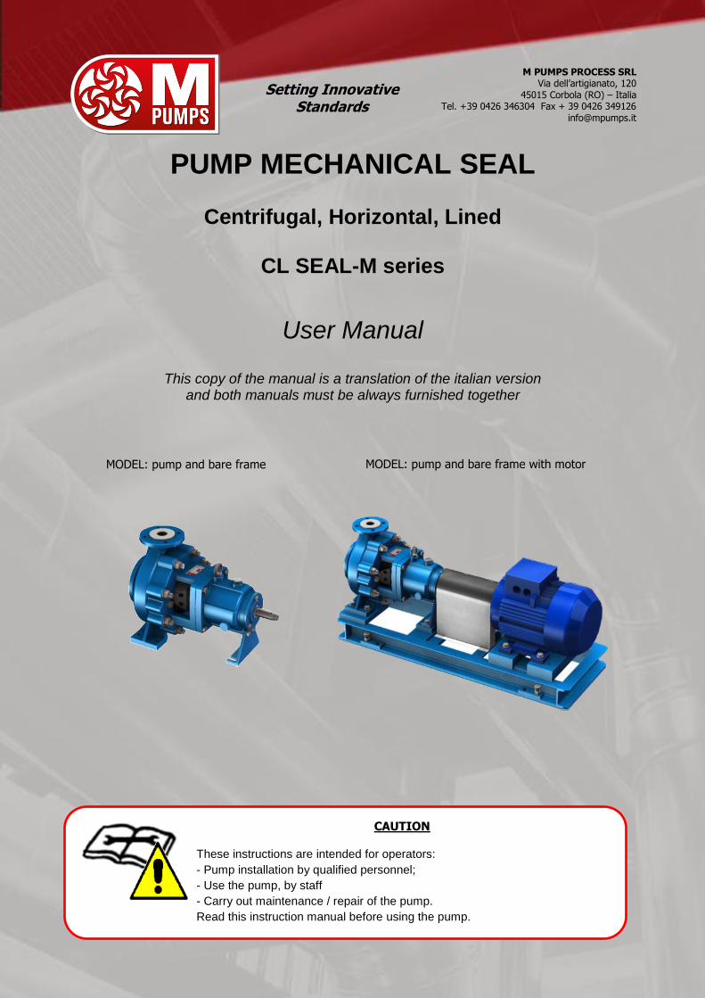
PUMP MECHANICAL SEAL
Centrifugal, Horizontal, Lined
CL SEAL-M series
User Manual
This copy of the manual is a translation of the italian version and both manuals must be always furnished together
MODEL: pump and bare frame
MODEL: pump and bare frame with motor
CAUTION
These instructions are intended for operators:
- Pump installation by qualified personnel;
- Use the pump, by staff
- Carry out maintenance / repair of the pump.
Read this instruction manual before using the pump.

Pag. 2/36Doc. ISM0117_MANUAL_CL SEAL-M-ISO_ENG_REV03.DOCX
The purpose of this document is to instruct to a responsible use on installation, operation and maintenance of pumps series CL SEAL-M. Please read it carefully before any activity pertaining to the pump it was provided for. The instructions in this manual are only valid for pumps it was provided for, and not for the facility in which the pumps will be installed. For a proper use of the system please refer to the instructions the manufacturer himself provided. In any case the instructions of the system have a greater value than those related to the pumps. For further information please contact M PUMPS PROCESS, useful information for a correct installation can also be found at - Hydraulic Institute Standards (USA).

ISM0117_MANUAL_CL SEAL-M-ISO_ENG_REV03.DOCX Pag. 3/36
Index 1. GENERAL AND SAFETY WARNINGS .......................................................................................................................................... 4
2. ICONS USED IN THE MANUAL ..................................................................................................................................................... 4
3. WARRANTY ................................................................................................................................................................................... 5
4. IDENTIFICATION NAMEPLATE .................................................................................................................................................... 5
5. DESCRIPTION OF THE PUMP ...................................................................................................................................................... 8
Applications ................................................................................................................................................................................. 8
6. TECHNICAL SPECIFICATIONS .................................................................................................................................................... 8
7. PERMISSIBLE LOADS ON FLANGES .......................................................................................................................................... 9
8. CL SEAL-M OPERATING LIMITS AND PERFORMANCE ........................................................................................................... 10
9. OVERALL DIMENSIONS ............................................................................................................................................................. 11
10. NOISE EMISSIONS AND VIBRATIONS ...................................................................................................................................... 12
11. IONIZING RADIATION ................................................................................................................................................................. 12
12. CHECKING UPON PUMP DELIVERY, STORAGE ...................................................................................................................... 12
13. TRANSPORT AND HANDLING ................................................................................................................................................... 12
14. ASSEMBLY, INSTALLATION, CONNECTIONS, COMMISSIONING AND ADJUSTMENTS ....................................................... 13
Assembly .................................................................................................................................................................................. 13 Connection of suction and feeding pump ..................................................................................................................................... 13 Electric connections ................................................................................................................................................................... 14 Checks for proper operation ....................................................................................................................................................... 14 Commissioning and training of staff ............................................................................................................................................ 14 Self-priming and not self-priming pumps ..................................................................................................................................... 15 Coupling of the pump to the motor ............................................................................................................................................. 15 Features and installation of the electric pump unit coming already assembled ............................................................................... 15 Alignment of the coupling .......................................................................................................................................................... 15 Alignment and coupling tolerances.............................................................................................................................................. 16
15. INTENDED USE OF THE PUMP. INCORRECT USE. OPERATION DESCRIPTION. PERSONAL PROTECTIVE EQUIPMENT DURING USE. ........................................................................................................................................................................................ 16
Intended use of the machine ...................................................................................................................................................... 16 Instructions for reasonably foreseeable proper use ...................................................................................................................... 16 Unintended use ......................................................................................................................................................................... 16
16. RESIDUAL RISKS AND PROTECTIVE MEASURES TO BE TAKEN .......................................................................................... 17
Descriptions of remaining residual risks ....................................................................................................................................... 17 Protective measures to be taken by the user and instructions ....................................................................................................... 17 Personal Protection Equipment to be worn .................................................................................................................................. 17
17. OPERATING LIMITS, RESIDUAL RISKS STILL REMAINING DESPITE THE SAFETY MEASURES TAKEN ............................ 17
Safety instructions mounted on the pump ................................................................................................................................... 18
18. INSTRUCTIONS AND PROCEDURES FOR TRAINING OF STAFF AND FOR EMERGENCY SITUATIONS ............................. 19
Reset method ............................................................................................................................................................................ 19 Fire-fighting equipment to be used: ............................................................................................................................................ 19 Emission/Dispersion of harmful substances: ................................................................................................................................ 19
19. MALFUNCTIONING, FAILURE, FAULT, ACCIDENT. MOST FREQUENT PROBLEMS: CAUSES AND REMEDIES................. 19
Malfunction ............................................................................................................................................................................... 19 Failure ...................................................................................................................................................................................... 19 Failure ...................................................................................................................................................................................... 20 Injury ....................................................................................................................................................................................... 20 The most frequent problems: problems, causes, remedies, residual risks ...................................................................................... 20
20. ROUTINE AND UNSCHEDULED MAINTENANCE ...................................................................................................................... 23
Cleaning the components and magnet ........................................................................................................................................ 23 Preventive periodic maintenance ................................................................................................................................................ 23 Shut-down and emptying of the fluid in the pump ....................................................................................................................... 24 Draining the oil contained in the pump ........................................................................................................................................ 24 Unscheduled maintenance .......................................................................................................................................................... 25
21. REPAIR AND SPARE PARTS ..................................................................................................................................................... 25
Disassembly of the pump ........................................................................................................................................................... 25 Disassembly of the pump ........................................................................................................................................................... 25 Re-assembly of the pump........................................................................................................................................................... 25
22. DECOMMISSIONING, SCRAPPING AND DISPOSAL OF MATERIALS ..................................................................................... 26
Decommissioning ....................................................................................................................................................................... 26 Scrapping and disposal .............................................................................................................................................................. 26
23. EXPLODED DRAWING OF THE PUMP - LIST OF COMPONENTS ............................................................................................ 26
24. Notes ........................................................................................................................................................................................... 27
25. APPENDIX A - Register of maintenance and periodic checks of the pump ............................................................................ 28
26. APPENDIX B ................................................................................................................................................................................ 30
Pag. 4/36Doc. ISM0117_MANUAL_CL SEAL-M-ISO_ENG_REV03.DOCX
1. GENERAL AND SAFETY WARNINGS
This manual has been prepared by M PUMPS PROCESS to provide the purchaser of the pump all the information necessary for its proper use and regular maintenance. Part of this manual is also the booklet of the electric motor when the pump is supplied fitted with it. For the purposes of safety and hygiene in the workplace, and to ensure a proper and durable use of the pump, the manual must be kept close to the device for any consultation. As an integral part of the pump, this manual must always accompany it. For any data that is not included or not inferable from this manual please contact M PUMPS PROCESS.
Do not use the pump before you have read and assimilated all safety rules and instructions in this manual. In case of damage or loss of the manual, immediately ask for a copy to M PUMPS PROCESS.. Failure to comply with the instructions contained in this manual exempts M PUMPS PROCESS from any liability. The pump and these instructions are intended for operators who make professional use and must be followed by qualified staff adequately trained, aware of the use, operation and the risks that the pump generates during its use; the experienced user has the best qualification possible. M PUMPS PROCESS reserves the right to make at any time changes deemed necessary to the improvement of the pump, taking care to update this manual as soon as possible. This reflects the State of the art at the time of marketing of the pump. In the event of ownership transfer of the pump, the user is invited to report to M PUMPS PROCESS the address of the new owner in order to facilitate the transmission of any additions to the manual to the new user. M PUMPS PROCESS reserves all rights in this manual, any total or partial reproduction is allowed without written permission.
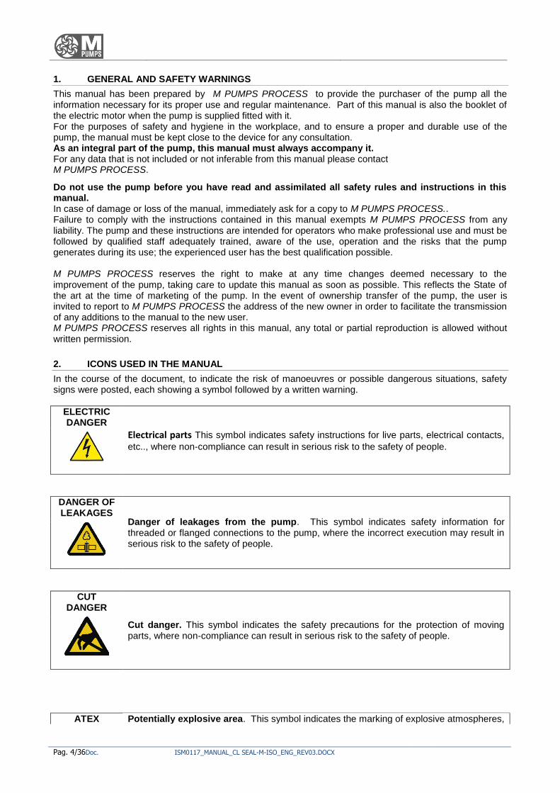
2. ICONS USED IN THE MANUAL
In the course of the document, to indicate the risk of manoeuvres or possible dangerous situations, safety signs were posted, each showing a symbol followed by a written warning.
ELECTRIC DANGER
Electrical parts This symbol indicates safety instructions for live parts, electrical contacts,
etc.., where non-compliance can result in serious risk to the safety of people.
DANGER OF LEAKAGES
Danger of leakages from the pump. This symbol indicates safety information for threaded or flanged connections to the pump, where the incorrect execution may result in serious risk to the safety of people.
CUT DANGER
Cut danger. This symbol indicates the safety precautions for the protection of moving parts, where non-compliance can result in serious risk to the safety of people.
ATEX Potentially explosive area. This symbol indicates the marking of explosive atmospheres,
ISM0117_MANUAL_CL SEAL-M-ISO_ENG_REV03.DOCX Pag. 5/36
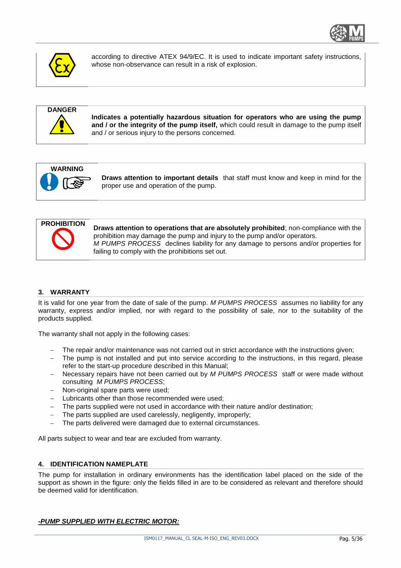
according to directive ATEX 94/9/EC. It is used to indicate important safety instructions, whose non-observance can result in a risk of explosion.
DANGER Indicates a potentially hazardous situation for operators who are using the pump and / or the integrity of the pump itself, which could result in damage to the pump itself and / or serious injury to the persons concerned.
WARNING Draws attention to important details that staff must know and keep in mind for the proper use and operation of the pump.
PROHIBITION Draws attention to operations that are absolutely prohibited; non-compliance with the prohibition may damage the pump and injury to the pump and/or operators. M PUMPS PROCESS declines liability for any damage to persons and/or properties for failing to comply with the prohibitions set out.
3. WARRANTY
It is valid for one year from the date of sale of the pump. M PUMPS PROCESS assumes no liability for any warranty, express and/or implied, nor with regard to the possibility of sale, nor to the suitability of the products supplied. The warranty shall not apply in the following cases:
The repair and/or maintenance was not carried out in strict accordance with the instructions given;
The pump is not installed and put into service according to the instructions, in this regard, please refer to the start-up procedure described in this Manual;
Necessary repairs have not been carried out by M PUMPS PROCESS staff or were made without consulting M PUMPS PROCESS;
Non-original spare parts were used;
Lubricants other than those recommended were used;
The parts supplied were not used in accordance with their nature and/or destination;
The parts supplied are used carelessly, negligently, improperly;
The parts delivered were damaged due to external circumstances.
All parts subject to wear and tear are excluded from warranty.
4. IDENTIFICATION NAMEPLATE
The pump for installation in ordinary environments has the identification label placed on the side of the support as shown in the figure: only the fields filled in are to be considered as relevant and therefore should be deemed valid for identification. -PUMP SUPPLIED WITH ELECTRIC MOTOR:

Pag. 6/36Doc. ISM0117_MANUAL_CL SEAL-M-ISO_ENG_REV03.DOCX
-PUMP SUPPLIED WITHOUT ELECTRIC MOTOR:
ISM0117_MANUAL_CL SEAL-M-ISO_ENG_REV03.DOCX Pag. 7/36
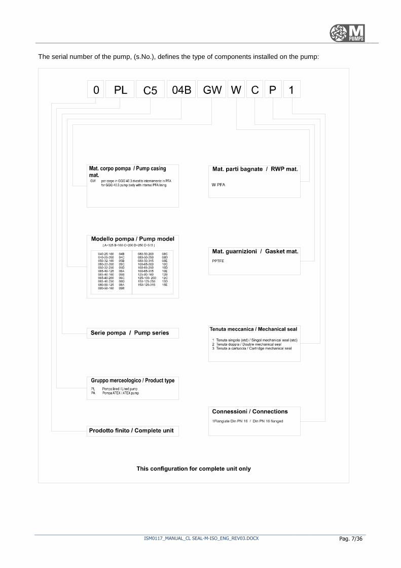
The serial number of the pump, (s.No.), defines the type of components installed on the pump:

Pag. 8/36Doc. ISM0117_MANUAL_CL SEAL-M-ISO_ENG_REV03.DOCX
5. DESCRIPTION OF THE PUMP
The pumps of the CL SEAL-M consist of a movable part: the IMPELLER, which performs rotary motion at high speed and fixed components: PUMP BODY (REQUIRED), SEALS, BEARINGS. The impeller consists of a disc on which are the blades which form divergent ducts divergent and is keyed on a shaft mounted on two rolling bearings. The pump to lift the fluid must be primed, that is, both the suction duct, and the body of the pump must always be full of liquid. This can be obtained by placing at the top of the suction duct FOOT VALVE (or NON-RETURN valve), which allows the liquid to pass only in one direction and precisely from the tank to the suction pipe.
Applications
- In general, this pump model is ideal for clean liquids, slightly contaminated; - the maximum operating pressure of the system, the permissible temperature and the maximum
rotation speed depend on the type of pump and are specified in the paragraph on "TECHNICAL DATA".
Other uses are not permitted, as they must comply with the conditions of use specified in paragraph on "TECHNICAL DATA ": the use of a pump in a system or with fluid conditions other than those the pump was designed for, can give rise to dangerous situations for the user.
6. TECHNICAL SPECIFICATIONS
The pumps described in this manual have the following features: Available with bare shaft or monoblock configuration, with the engine directly keyed to the pump support. CL SEAL-M Connections: Flanged DIN PN16 ANSI B 16.5 150lbs; Maximum viscosity: 200 cps; Maximum operating pressure: 16 BARS (standard, CL SEAL-M) 450 mc/h flow rate; Discharge head up to 136 m;
Operating temperatures up to +120°C; Electric motor power: from 1.5kW up to 90kW; Maximum engine speed: up to 3500 rpm; Weight of the pump: from 35 to 300 kg;
Features of electric motors: network frequency 50 Hz network frequency 60 Hz 2 pins 2900 rpm 3500 rpm 4 pins 1450 rpm 1750 rpm
WARNING WARNING: If the pump is driven by inverter, keep it within recommended rotation
limits..

ISM0117_MANUAL_CL SEAL-M-ISO_ENG_REV03.DOCX Pag. 9/36
7. PERMISSIBLE LOADS ON FLANGES
PUMP SIZE Fx; N Fy; N Fz; N Fr; N Mx; Nm My; Nm Mz; Nm Mr; Nm
Suct. port
Disc. port
Suct. port
Disc. port
Suct. port
Disc. port
Suct. port
Disc. port
Suct. port
Disc. port
Suct. port
Disc. port
Suct. port
Disc. port
Suct. port
Disc. port
40-25-160 417 250 367 233 333 283 650 433 433 300 300 200 350 233 633 433
40-25-200 417 250 367 233 333 283 650 433 433 300 300 200 350 233 633 433
50-32-160 550 300 500 283 450 350 867 550 467 367 333 250 383 283 683 533
50-32-200 550 300 500 283 450 350 867 550 467 367 333 250 383 283 683 533
50-32-250 550 300 500 283 450 350 867 550 467 367 333 250 383 283 683 533
65-50-125 700 367 617 333 567 417 1100 650 500 433 367 300 400 350 733 633
65-50-160 700 367 617 333 567 417 1100 650 500 433 367 300 400 350 733 633
65-40-200 700 367 617 333 567 417 1100 650 500 433 367 300 400 350 733 633
65-40-250 700 367 617 333 567 417 1100 650 500 433 367 300 400 350 733 633
80-65-125 833 500 750 450 683 550 1317 867 533 467 383 333 433 383 783 683
80-65-160 833 500 750 450 683 550 1317 867 533 467 383 333 433 383 783 683
80-50-200 833 500 750 450 683 550 1317 867 533 467 383 333 433 383 783 683
80-50-250 833 500 750 450 683 550 1317 867 533 467 383 333 433 383 783 683
80-50-315 833 500 750 450 683 550 1317 867 533 467 383 333 433 383 783 683
100-65-200 1117 617 1000 567 900 700 1750 1100 583 500 417 367 483 400 867 733
100-65-250 1117 617 1000 567 900 700 1750 1100 583 500 417 367 483 400 867 733
100-65-315 1117 617 1000 567 900 700 1750 1100 583 500 417 367 483 400 867 733
125-80-160 1317 750 1183 683 1067 833 2067 1317 700 533 500 383 633 433 1017 783
125-100-200 1317 1000 1183 900 1067 1117 2067 1750 700 583 500 417 633 483 1017 867
150-125-250 1667 1183 1500 1067 1350 1317 2617 2067 833 700 583 500 683 633 1217 1017
150-125-315 1667 1183 1500 1067 1350 1317 2617 2067 833 700 583 500 683 633 1217 1017

Pag. 10/36Doc. ISM0117_MANUAL_CL SEAL-M-ISO_ENG_REV03.DOCX
8. CL SEAL-M OPERATING LIMITS AND PERFORMANCE

ISM0117_MANUAL_CL SEAL-M-ISO_ENG_REV03.DOCX Pag. 11/36
9. OVERALL DIMENSIONS

Pag. 12/36Doc. ISM0117_MANUAL_CL SEAL-M-ISO_ENG_REV03.DOCX
10. NOISE EMISSIONS AND VIBRATIONS
The noise level of a pump depends mainly on its operating conditions. The operating conditions of the pump during measurements are: pump coupled to an electric motor on test bench with fluids pumping. The A-weighed sound pressure level measured in front and at the side of the pump is below 85 dB(a), measured at a metre away.
11. IONIZING RADIATION
The pump does not emit any type of ionizing radiation that may cause harm to people.
12. CHECKING UPON PUMP DELIVERY, STORAGE
All M PUMPS PROCESS are tested before shipping and carefully packed for transport: upon receipt of the pump, make sure it has not been damaged during transport. If there are any problems, contact the carrier immediately and inform M PUMPS PROCESS about the accident occurred. So that the pump is preserved over time in the best way possible, we recommend storing it away from the sun, from weathering and dust, when it is not immediately installed or not used for long periods. The closing plugs of the input and output connections of the fluid should not be removed until installation. If supplied with motor, please also apply the storage instructions provided by its manufacturer himself. The maximum excursion of permissible temperature during storage, preservation and use must be between -15 and +40°C with humidity between 10 and 90%.
13. TRANSPORT AND HANDLING
It is advisable to perform a preliminary check of the pump at the time of delivery to detect and report any damage incurred during transport and handling. In case of damage you should not perform any operation, just contact M PUMPS. The precautions to be taken to ensure the stability of the pump concern the possible sliding and tilting caused by handling and transport, which must be prevented by fixing with ropes the pump body to the body of the transport mean it is loaded on. The pump or electro-pump unit are too heavy to be moved manually. During the move, with the pump positioned on a pallet, open the forks at their maximum and perform the loading / unloading. The pump can be raised as indicated in the figure of a stable lifting:
Bare shaft pump, without motor Bare shaft pump, with motor
Centre of gravity about in the middle Centre of gravity about in the middle
These operations must be performed by trained personnel who are informed on the hazards involved.

ISM0117_MANUAL_CL SEAL-M-ISO_ENG_REV03.DOCX Pag. 13/36
PROHIBITION - It is forbidden to lift the pump using as anchor points structures other than those specially created and reported.
- It is not possible to lift an electro-pump unit using the lifting eyebolt of an electric motor.
- During the early lifting stages all the surrounding area is to be considered a danger zone, and staff not in charge of such operations must be evacuated.
There is the possibility of transporting and handling the pump slinging it using points specifically designed to this end: you must ensure that shackles and chains or straps are suitable to withstand the weight of the pump (described in "TECHNICAL DATA" paragraph).
14. ASSEMBLY, INSTALLATION, CONNECTIONS, COMMISSIONING AND ADJUSTMENTS
Assembly
Install the pump on a solid basis as close as possible to the liquid to be pumped, under its level, in such a position so as to make easier the maintenance and inspection operations Do not allow the pump to take sharp shots as this may damage the magnets of the internal and external rotor or the silicon carbide supports. Make sure that the heated air coming from other units will not badly affect the environment of the pump; the ambient temperature should not exceed 40°C, for higher temperatures please contact your M PUMPS distributor; also ensure the free circulation of cooling air for at least a quarter the diameter of the motor, as both the motor and the pump must be able to dissipate the heat by convection with the ambient air. Insufficient cooling could lead to high surface temperatures of the bearing housing, insufficient lubrication and premature breakage of the bearings. It is useful to monitor their surface temperature. It is always the responsibility of the operator to maintain limited the coolant temperature, so that not to overheat the pump: switch off the pump in case of abnormal pressure fluctuations and flow decreases.
WARNING Normally you have to mount the pump in horizontal position. If mounted inclined or vertical, the pump, or better to say the suction inlet, must be placed in the lower part. Leave a space of at least 50 cm between the pump and any walls or pipes;
The liquid being pumped can reach high temperatures: from 60°C it is necessary to install shielding to prevent contact with hot components of the pump;
Connect to the grounding system the whole pump body, to avoid the build-up of static electricity;
If the pumped liquid can be dangerous to people and the environment, the user must take steps for a simple and quick remedy in case of leakages due to breakages/replacement/maintenance of the pump.
Connection of suction and feeding pump
For a correct assembly aimed at optimum use of the pump, you must apply the following requirements:
The pipes must be supported and kept in line regardless of the pump, up to its connections, so as not to burden on it;
The connections must not be subjected to stresses during operation;
The suction piping must be built with the fewest restrictions possible, in such a way as to have the greatest NPSH available;
The length of the pipes, in particular that of the suction pipe, must be minimized;
The pipe must be fitted in such a way so that it is impossible the formation of air pockets; if this is not possible, it must be provided the possibility of bleeding the air from the highest point;
During suction only use full flow section valves;
NO YES

Pag. 14/36Doc. ISM0117_MANUAL_CL SEAL-M-ISO_ENG_REV03.DOCX
If the suction pipe is larger than the suction flange, you must use an eccentric reductions towards
the suction flange, in order to prevent the formation of air pockets and vortices;
If there is a possibility that the maximum operating pressure can be overcome, for example due to
excessive intake pressure, it is necessary to take appropriate measures by incorporating a safety valve in the pipeline;
Avoid the use of quick-closing valves, since sudden pressure changes cause water hammering, very
damaging for both the pump and pipes;
Be sure, before installing the pump, that the suction line is clean and/or provided with a filter to
protect the impeller and supports from damage caused by debris or other foreign particles, especially at system commissioning.
Electric connections
DANGER The pump is supplied with or without electrical motor: only qualified personnel
must make the mechanical connection of the pump to the motor (for models without
motor) and the electrical connections of the motor to the electrical system. Carefully read the instructions on the manual provided by the manufacturer of the motor before carrying
out the installation.
Ensure that it is not possible to operate the motor during maintenance work to the electric pump unit.
Checks for proper operation
We recommend the installation of a pressure gauge in both the suction and delivery pipes to allow the
operator to easily check the correct operation of the pump in relation to the required operating point: in the event of cavitation or other malfunction, evident pressure fluctuations occur.
Check the differential pressure of the pump between the suction and delivery connections to make sure it
works at the operating point expected. Check whether the absolute suction pressure is not so low so as to cause cavitation in the pump.
WARNING The absolute pressure at pump suction (expressed in metres) must overcome by at least
0,5÷1 m, the vapour pressure of the pumped liquid, in order to avoid the risk of cavitation.
Cavitation should always be avoided as very dangerous for the structure of the pump.
Commissioning and training of staff
In relation to the proper commissioning of the pump and checks to be carried out before, during and after it, refer to APPENDIX B, which must be duly completed and returned to M PUMPS, to activate the warranty covering the product.
Pumps by M PUMPS of the CL SEAL-M series are not reversible therefore the direction of rotation cannot be reversed. The correct direction of rotation is counter-clockwise: if you stand in front of the pump body, an arrow indicates the correct direction of rotation; reversing the direction of rotation may damage the pump. To check the direction of rotation, give power and immediately cut-it off to the motor, and then observe the direction of rotation.
DIRECTION OF ROTATION:
Make sure that the rotating parts, such as the flexible coupling or other related components, are always protected when the pump is running.
Operators who use the pump must have carefully read this use and maintenance manual, as well as being
qualified to fully understand the features of the device and the ability to identify its problems, if any. By carrying out the operations indicated in the previous paragraph and all of the checks indicated on the

ISM0117_MANUAL_CL SEAL-M-ISO_ENG_REV03.DOCX Pag. 15/36
maintenance register, the pump is ready for use.
Self-priming and not self-priming pumps
The CL SEAL-M series pumps are not self-priming: make sure that the pump is filled with liquid and, if necessary, vented before start-up; in the event that the suction height is negative, with respect to the delivery, dry operation must be avoided.
Coupling of the pump to the motor
If the pump and the electric motor are to be coupled, observe the sequence of the following steps to proceed with the installation:
Fit flush the two elastic coupling halves on the pump shaft and on that of the motor.
Place the pump on the base, by placing shims (about 2-5 mm) under the feet of the body and the foot of the oil case, then secure it with the screws provided.
Place the electric motor by adjusting the shims under the feet, so that the two shafts (pump and motor) are coaxial.
Leave a space of 3 mm between the two elastic coupling halves, then stop the motor with the screws provided.
Features and installation of the electric pump unit coming already assembled
The shafts of the pump and motor have already been properly adjusted and aligned as an extension of one on the other. For installation in the plant it is just necessary to respect the sequence of operations:
The base must be placed on a horizontal plane, also using shims;
Tighten the nuts on the fixing bolts;
Check the alignment of the shafts of the pump and the electric motor and repeat the alignment operations if necessary (described in "Alignment of the coupling" paragraph).
Alignment of the coupling
Place a straight edge on the coupling. Insert or remove all shims necessary to bring the electric motor at the correct height, so that the bottom part of the straight edge rests on both halves of the coupling for the entire length;
Repeat the same check on both sides of the coupling, at the height of the shaft. Rotate the shaft of the electric motor so that the bottom part of the straight edge touches both halves of the coupling for the entire length;
Re-assembly the guard.
Pag. 16/36Doc. ISM0117_MANUAL_CL SEAL-M-ISO_ENG_REV03.DOCX
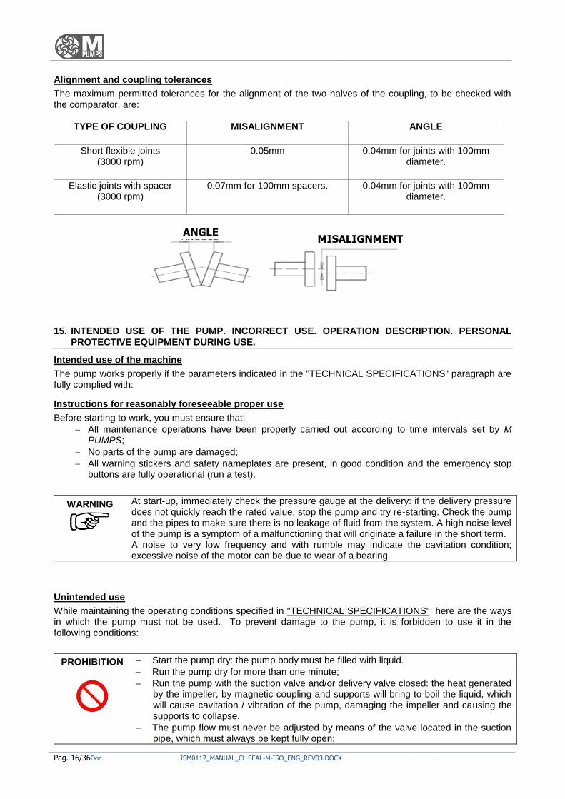
Alignment and coupling tolerances
The maximum permitted tolerances for the alignment of the two halves of the coupling, to be checked with the comparator, are:
TYPE OF COUPLING MISALIGNMENT ANGLE
Short flexible joints
(3000 rpm)
0.05mm 0.04mm for joints with 100mm diameter.
Elastic joints with spacer
(3000 rpm)
0.07mm for 100mm spacers. 0.04mm for joints with 100mm diameter.
15. INTENDED USE OF THE PUMP. INCORRECT USE. OPERATION DESCRIPTION. PERSONAL PROTECTIVE EQUIPMENT DURING USE.
Intended use of the machine
The pump works properly if the parameters indicated in the "TECHNICAL SPECIFICATIONS" paragraph are fully complied with:
Instructions for reasonably foreseeable proper use
Before starting to work, you must ensure that:
All maintenance operations have been properly carried out according to time intervals set by M PUMPS;
No parts of the pump are damaged;
All warning stickers and safety nameplates are present, in good condition and the emergency stop buttons are fully operational (run a test).
WARNING At start-up, immediately check the pressure gauge at the delivery: if the delivery pressure does not quickly reach the rated value, stop the pump and try re-starting. Check the pump and the pipes to make sure there is no leakage of fluid from the system. A high noise level of the pump is a symptom of a malfunctioning that will originate a failure in the short term. A noise to very low frequency and with rumble may indicate the cavitation condition; excessive noise of the motor can be due to wear of a bearing.
Unintended use
While maintaining the operating conditions specified in "TECHNICAL SPECIFICATIONS" here are the ways in which the pump must not be used. To prevent damage to the pump, it is forbidden to use it in the following conditions:
PROHIBITION
Start the pump dry: the pump body must be filled with liquid.
Run the pump dry for more than one minute;
Run the pump with the suction valve and/or delivery valve closed: the heat generated by the impeller, by magnetic coupling and supports will bring to boil the liquid, which will cause cavitation / vibration of the pump, damaging the impeller and causing the supports to collapse.
The pump flow must never be adjusted by means of the valve located in the suction pipe, which must always be kept fully open;
ANGLE MISALIGNMENT

ISM0117_MANUAL_CL SEAL-M-ISO_ENG_REV03.DOCX Pag. 17/36
Start and/or operate the pump if leakages are noticed;
Changing the operating conditions of the pump without consulting the M PUMPS technical office;
Loosen the connections of the pump while it is under pressure;
Try to clean the pump while it is running;
Run the pump in the opposite direction to that indicated in the pump body;
Run the pump at temperatures and pressures exceeding the rated ones;
Pump liquids containing ferromagnetic particles of any size, or substances that can wear away or chemically attack the internal parts of the pump;
Remove the safety devices and guards when the pump is running;
Take action on moving parts;
Take action on electrical parts installed without first cutting off the power supply, do not alter the safety devices installed, do not operate repeatedly the command buttons.
DANGER It is deemed incorrect any use of the pump other than that indicated in the paragraph in "Instructions for reasonably foreseeable proper use". M PUMPS disclaims any liability for damage to property and injury to persons resulting from uses for which the pump has not been specifically designed and built.
16. RESIDUAL RISKS AND PROTECTIVE MEASURES TO BE TAKEN
Descriptions of remaining residual risks
Although all protective measures incorporated into the design of the pump have been taken, the main dangers associated with its use are the following:
Danger of projection of sketches of process fluids which may be caustic or burning, as a result of improper installation and sudden failure of the pump body and hydraulic connections;
Danger of cuts to hands for burrs on the pump body;
Explosion of the pump for the formation of explosive mixture inside the body of the device resulting from its improper use.
Protective measures to be taken by the user and instructions
PROHIBITION It is strictly forbidden to remove or tamper with the safety devices. Before using the pump check the correct fitting of mechanical guards. Any tampering will void the warranty and the liability of M PUMPS towards the users of the device.
Only maintainers may perform maintenance operations that affect the safety devices.
Personal Protection Equipment to be worn
The protective measures that must be taken during this phase are: the adoption of anti-acid and anti-static overalls, anti-splash goggles, gloves protecting from mechanical, chemical agents, and safety shoes. Avoid the use of accessories (necklaces, bracelets, etc..) and clothing undone, torn or dangling that could get caught in moving parts of the pump.
17. OPERATING LIMITS, RESIDUAL RISKS STILL REMAINING DESPITE THE SAFETY MEASURES TAKEN
The dangers that have not been deleted with the safety measures taken on the pump can be reduced/eliminated if operators apply such management measures as a result of the fact of having to:
Keep all safety instructions and all the nameplates and labels intact and replace them when necessary, periodically verifying their good condition;
Do not take substances that can alter their physical or mental capacity (alcohol, medicines, drugs, etc.);
Do not use, without permission, spare parts no identical to the originals ones or components not approved by M PUMPS;
Do not perform any changes or structural intervention without previous specific approval by M PUMPS;
Following to shocks suffered accidentally by the pump, carry out a visual inspection to ascertain the

Pag. 18/36Doc. ISM0117_MANUAL_CL SEAL-M-ISO_ENG_REV03.DOCX
absence of any damage, if required send the pump to M PUMPS;
Check, after a long downtime period, that the pump is still intact and that the parts subject to wear and tear and in good conditions and properly operating. If necessary replace with spare parts identical to the original ones.
WARNING Each misuse or negligence until now listed may cause:
Immediate cancellation of technical assistance by M PUMPS;
Disclaimer of M PUMPS for damages to properties, animals or people.
Safety instructions mounted on the pump
The safety and warning signs mounted on the pump must be complied to, some of them must also be replaced in case they turn out to be illegible, and are the following:
Warning No.
Description of warning signs applied
Symbol/indication Quantity Notes
1. Marking nameplate
M PUMPS.
Reported in paragraph
"IDENTIFICATION NAMEPLATE"
1 Restore if
unreadable
2. Label for "follow the instructions on the manual"
1 /
3. Label with "fill with oil before starting"
1 /
4. Label with "check for proper motor-pump alignment, before start-up"
1 /
5. Label on direction of rotation and indication on not to start when dry.
1 Restore if
unreadable
6. Hydrotest label.
1 /
7. Quality control label
Assembly.
1 Internal use
ISM0117_MANUAL_CL SEAL-M-ISO_ENG_REV03.DOCX Pag. 19/36
18. INSTRUCTIONS AND PROCEDURES FOR TRAINING OF STAFF AND FOR EMERGENCY SITUATIONS
The operators responsible for the various service life stages of the pump must be:
Maintainers: Personnel educated and trained in the proper handling of goods with the use of tools and lifting equipment;
Pipes and electrical connections installers: qualified and trained staff to work on live electrical systems, personnel with experience in the field of hydraulic installations;
Users: Professional staff trained in the instructions for use of this pump. In case of emergency:
Tell people who is close to specific dangerous situation, also gesturing with the arms;
Stop the pump by pressing the nearest emergency stop button;
Reset method
To resume normal operation, you must eliminate all the causes that led to the emergency situation, possibly by repairing or replacing parts that have suffered damage.
WARNING After the activation of the protection devices, it is necessary to find the cause triggering them, before resuming the operations.
Fire-fighting equipment to be used:
In case of fire involving the pump, you can use water or foam liquid only after having cut-off the power supply, or use a fire extinguisher with extinguishing agent, like powder. Do not use CO2 because, being launched at -79°C, it may react violently with hot parts.
Emission/Dispersion of harmful substances:
The fluid contained in the system could be released into the atmosphere as a result of an intervention or a breakage of the pump.
19. MALFUNCTIONING, FAILURE, FAULT, ACCIDENT. MOST FREQUENT PROBLEMS: CAUSES AND REMEDIES
Malfunction
There are no components of the pump which cause malfunctions able to restrict or cause unsafe operations.
At paragraph "The most frequent Problems: causes and remedies" this section is discussed in a more
thoroughly way.
Failure
In case of failure of mechanical parts you must immediately restore initial safety conditions, by replacing or repairing the parts that have deficiencies. In case of failure of the electric pump unit proceed as follows:
Cut the power supply to the pump motor or switch off the combustion engine;
Close the suction and delivery valves;
Find the cause of the failure by checking "The Most frequent Problems: problem, causes, remedies, residual risks". The failures of a pumping system can be attributed to:

Pag. 20/36Doc. ISM0117_MANUAL_CL SEAL-M-ISO_ENG_REV03.DOCX
A failure of the pump;
A failure or defect of the pipes;
A failure due to installation or installation or commissioning not properly carried out;
Incorrect choice of the pump.
Failure
Under conditions of pump failure tell the staff in its vicinity about the problem occurred.
Injury
In the event of an injury, report the emergency situation to the Manager of the plant, in order to secure the plant to reach with the emergency team the place where the accident occurred.
The most frequent problems: problems, causes, remedies, residual risks
INADEQUATE FLOW RATE
Causes
Remedies/actions to be taken
The prevalence required exceeds that provided for the pump.
Reduce total prevalence of the system if possible. Check that the delivery valve is fully open. Replace the pump with a larger one. Ask for advice at your distributor by M PUMPS.
The pump rotates in the opposite direction.
Check the direction of rotation. Refer to section 3.5 of this manual.
Air or steam trapped in the suction pipe. Check for trapped air or steam. Refer to section 3.4 of this manual.
The liquid contains air or steam. The liquid produces foam.
Check the presence of vortices in the suction line. Insert the baffles in the fuel tank to prevent the formation of vortices. Mount a tank having sufficient capacity, in the suction line, to allow the entrained gas to separate from the liquid.

ISM0117_MANUAL_CL SEAL-M-ISO_ENG_REV03.DOCX Pag. 21/36
Suction pressure insufficient, with the generation of cavitation and loss of efficiency.
Decrease the negative height of suction, increase the suction head. Check that the suction is not obstructed or there are no blockages. Reduce the temperature of the liquid Increase the diameter of the suction pipes. Decrease the length of the suction pipes. Fully open the suction valve. Check the viscosity of the liquid, refer to the "TECHNICAL DATA" in this manual, raise the temperature of the liquid if necessary.
Wear suction elements, pressing devices, or the impeller.
Check the condition of the internal parts. Replace if worn, refer to Chapter 10 of this manual.
The liquid temperature is close to the boiling point.
Reduce the temperature of the liquid
NO FLOW RATE
Causes
Remedies/actions to be taken
The pump is disconnected. Re-connect the pump. Refer to section 3.5.1 of this manual. Verify the presence of air leaks in the suction line.
Suction line blocked. Make sure that there are no blind, clogged pipes, or closed valves.
The magnetic coupling decouples Contact your M PUMPS distributor.
The engine has stopped Check the power supply to the engine. Carry out a visual check of the engine.
EXCESSIVE FLOW RATE
Causes
Remedies/actions to be taken
The prevalence required is lower than that provided by the pump.
Reduce the speed of rotation, if possible; partially close the delivery valve.
ENGINE OVERHEATING AND STOP
Excessive density of the liquid being pumped.
If possible, reduce the speed of the electric motor. Contact your M PUMPS distributor.
The pump has seized or is about to seize.
Check the free rotation of the impeller. Check for any internal obstructions. If the pump was recently services, recheck the accuracy of indoor clearances.
Pag. 22/36Doc. ISM0117_MANUAL_CL SEAL-M-ISO_ENG_REV03.DOCX
Motor and pump are misaligned. Refer to section 3.8 of this manual.
The motor bearings are damaged or worn.
Replace the motor bearings, investigate the causes of the breakage.
Down-sized engine Fit a more powerful engine (check in advance with your M PUMPS distributor).
Motor overload threshold set incorrectly. Check the safety settings of the engine.
The protective device against dry running of the motor (where any) has failed or has been set incorrectly.
Check flow rate decreases in liquid delivered or sucked.
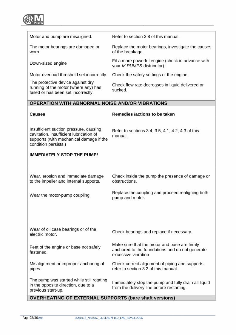
OPERATION WITH ABNORMAL NOISE AND/OR VIBRATIONS
Causes
Remedies /actions to be taken
Insufficient suction pressure, causing cavitation, insufficient lubrication of supports (with mechanical damage if the condition persists.) IMMEDIATELY STOP THE PUMP!
Refer to sections 3.4, 3.5, 4.1, 4.2, 4.3 of this manual.
Wear, erosion and immediate damage to the impeller and internal supports.
Check inside the pump the presence of damage or obstructions.
Wear the motor-pump coupling Replace the coupling and proceed realigning both pump and motor.
Wear of oil case bearings or of the electric motor.
Check bearings and replace if necessary.
Feet of the engine or base not safely fastened.
Make sure that the motor and base are firmly anchored to the foundations and do not generate excessive vibration.
Misalignment or improper anchoring of pipes.
Check correct alignment of piping and supports, refer to section 3.2 of this manual.
The pump was started while still rotating in the opposite direction, due to a previous start-up.
Immediately stop the pump and fully drain all liquid from the delivery line before restarting.
OVERHEATING OF EXTERNAL SUPPORTS (bare shaft versions)
ISM0117_MANUAL_CL SEAL-M-ISO_ENG_REV03.DOCX Pag. 23/36
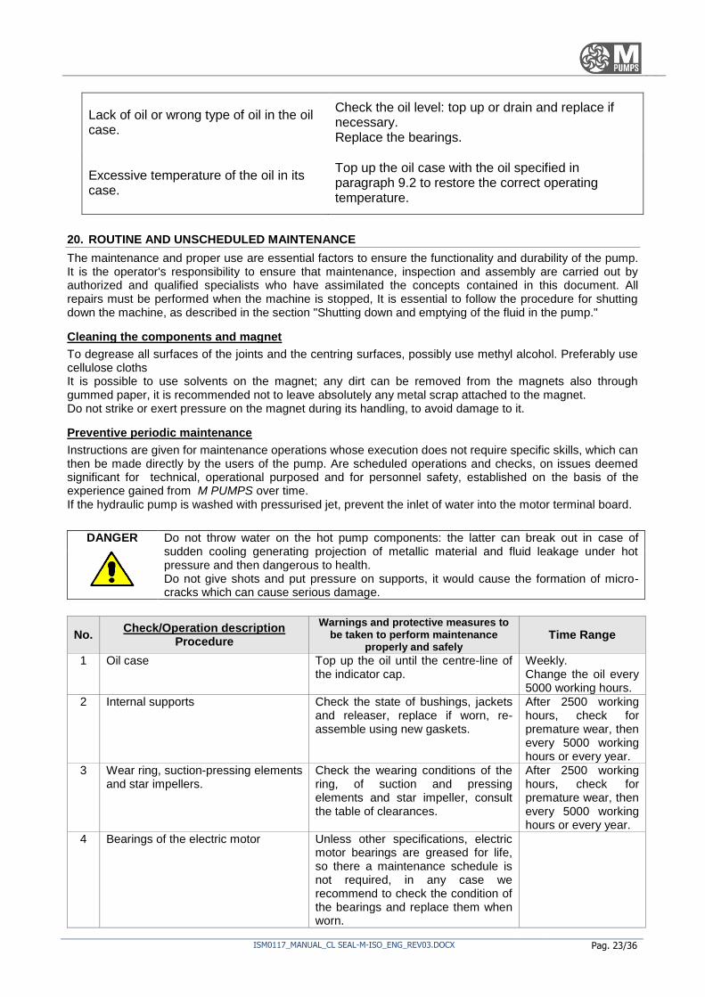
Lack of oil or wrong type of oil in the oil case.
Check the oil level: top up or drain and replace if necessary. Replace the bearings.
Excessive temperature of the oil in its case.
Top up the oil case with the oil specified in paragraph 9.2 to restore the correct operating temperature.
20. ROUTINE AND UNSCHEDULED MAINTENANCE
The maintenance and proper use are essential factors to ensure the functionality and durability of the pump. It is the operator's responsibility to ensure that maintenance, inspection and assembly are carried out by authorized and qualified specialists who have assimilated the concepts contained in this document. All repairs must be performed when the machine is stopped, It is essential to follow the procedure for shutting down the machine, as described in the section "Shutting down and emptying of the fluid in the pump."
Cleaning the components and magnet
To degrease all surfaces of the joints and the centring surfaces, possibly use methyl alcohol. Preferably use cellulose cloths It is possible to use solvents on the magnet; any dirt can be removed from the magnets also through gummed paper, it is recommended not to leave absolutely any metal scrap attached to the magnet. Do not strike or exert pressure on the magnet during its handling, to avoid damage to it.
Preventive periodic maintenance
Instructions are given for maintenance operations whose execution does not require specific skills, which can then be made directly by the users of the pump. Are scheduled operations and checks, on issues deemed significant for technical, operational purposed and for personnel safety, established on the basis of the experience gained from M PUMPS over time. If the hydraulic pump is washed with pressurised jet, prevent the inlet of water into the motor terminal board.
DANGER Do not throw water on the hot pump components: the latter can break out in case of sudden cooling generating projection of metallic material and fluid leakage under hot pressure and then dangerous to health. Do not give shots and put pressure on supports, it would cause the formation of micro-cracks which can cause serious damage.
No. Check/Operation description
Procedure
Warnings and protective measures to be taken to perform maintenance
properly and safely Time Range
1 Oil case Top up the oil until the centre-line of the indicator cap.
Weekly. Change the oil every 5000 working hours.
2 Internal supports Check the state of bushings, jackets and releaser, replace if worn, re-assemble using new gaskets.
After 2500 working hours, check for premature wear, then every 5000 working hours or every year.
3 Wear ring, suction-pressing elements and star impellers.
Check the wearing conditions of the ring, of suction and pressing elements and star impeller, consult the table of clearances.
After 2500 working hours, check for premature wear, then every 5000 working hours or every year.
4 Bearings of the electric motor Unless other specifications, electric motor bearings are greased for life, so there a maintenance schedule is not required, in any case we recommend to check the condition of the bearings and replace them when worn.

Pag. 24/36Doc. ISM0117_MANUAL_CL SEAL-M-ISO_ENG_REV03.DOCX
TABLE OF RECOMMENDED OIL: (for ambient temperatures above 15°C, according to ISO VG 68 classification)
BP HPL 68
CHEVRON EP industrial oil 68
Texaco Rando Oil HDC 68
TOTAL Azolla 68
Shell Tellus 68
Mobil DTE Heavy Medium ISO 68
STATOIL HYDRAWAY HV 68 Esso Teresso 68
AGIP OSO 68
WARNING
In Appendix A is a list of maintenance and periodic checks to be completed each time you perform this type of operations.
Shut-down and emptying of the fluid in the pump
DANGER
The pumps included in this series are used to pump liquids that are, generally, harmful to health, thus use suitable protective equipment before starting draining, disassembly and maintenance operations.
Close the delivery valve, making sure that the pump runs with the valve closed for no more than a few seconds.
Stop the pump.
Turn off the flushing and / or cooling / heating systems of liquid in a time appropriate, depending on the ongoing process.
Before proceeding with the disassembly, it is necessary to empty the pump according to the following steps:
Close the valves in the suction pipe and in the cooling or rinsing pipe of the shaft sealing system;
Remove the drain plug, this preserves the pump, in particular in cases where the ambient temperature may go below the freezing point of the liquid;
At the end re-positions the drain plug. If fluids hazardous for health are pumped, wear suitable personal protective equipment for accident prevention before coming into contact with the liquid.
Draining the oil contained in the pump
If the pump is designed with oil-lubricated bearings (versions with bare shaft):
Remove the oil drain plug.
Drain the oil collecting it without release into the environment;
Re-position the oil drain plug. If fluids hazardous for health are pumped, wear suitable personal protective equipment for accident prevention before coming into contact with the liquid.

ISM0117_MANUAL_CL SEAL-M-ISO_ENG_REV03.DOCX Pag. 25/36
Unscheduled maintenance
The unscheduled maintenance operations relate to activities that are outside of those normally programmable and executable; they require specific technical expertise by qualified staff and therefore it is recommended to contact M PUMPS . The address is in the header of each page of this manual.
DANGER In case you need to disassemble the pump, it must be remembered that the liquid should be collected and disposed of in accordance with current environmental laws. In the case in which the pump is to be sent to M PUMPS it must be reclaimed, and must not contain any trace of pumped liquids.
21. REPAIR AND SPARE PARTS
The pump must always be kept in optimal working conditions. Most of the spare parts shall indicate clear and comprehensive references for their identification. It is important that the parts of the pump are replaced by similar parts, such that they can be considered of equivalent quality and safety: to order original spare parts, contact M PUMPS referring to the pump model, serial number, description of the component and the desired quantity. When any elements with rust, cracks, etc... is detected, you must perform all replacements/repairs necessary to restore the safety operating conditions of the pump. For added safe, you should always ask for an opinion to M PUMPS before carrying out any operation. The periodical maintenance stated in chapter "PERIODIC AND UNSCHEDULED MAINTENANCE" should be carried out.
Disassembly of the pump
In the event that the pump has pumped hot liquids, make sure it has cooled before disassembly. The pump could have pumped liquid hazardous to health: it is therefore necessary to wear personal protective equipment for accident prevention. The activities of disassembly and maintenance of the pump must be carried out in full compliance with current regulations. In particular the following spare parts affect the health and safety of operators acting on them:
WARNING M PUMPS disclaims any liability for damage to things and people and will void the warranty if you install unsuitable components with non-equivalent quality.
MAGNETIC The pumps built by M PUMPS contain extremely strong magnets. The use of tools and
non-ferromagnetic work surfaces is highly recommended. The Department in which you perform the maintenance must be clean and free of ferrous particles that can be attracted by magnets. Pay attention to the strong magnetic attraction when you disassemble/reassemble the motor-outer magnet, the pump, because tools may fall or the magnet itself causing crushing and bruising of the fingers, as well as projection of high-velocity objects in the environment.
Disassembly of the pump
In the case of bare shaft system, with coupling and spacer, you can remove the internal assembly even without removing the electric motor. Keeping in mind the instructions described in Chapter 9 "Periodic Preventive Maintenance", proceed disassembling as follows:
Re-assembly of the pump
To reassemble the pump, follow the instructions in reverse order.

Pag. 26/36Doc. ISM0117_MANUAL_CL SEAL-M-ISO_ENG_REV03.DOCX
Thoroughly clean each component before assembly, making sure that all parts are free from dirt, metallic particles, etc.
22. DECOMMISSIONING, SCRAPPING AND DISPOSAL OF MATERIALS
Decommissioning
In case of long downtime periods it is advisable to apply a few simple precautions in order to preserve the pump correctly. Operate the pump with clean water (or other appropriate solvent compatible with the pump materials) for several minutes, in order to avoid the risk of internal precipitation or fouling. Disassemble power/water supply systems and place the pump in a covered place, protected from weathering. When starting-up after a long downtime period, strictly apply all indications for the commissioning process described at the beginning of this manual.
WARNING A good storage will save you from unpleasant drawbacks during re-commissioning. M PUMPS disclaims any liability for machines stored incorrectly. If you intend not to use this pump any more, it is recommended to make it inoperative.
Scrapping and disposal
The user must fulfil the law on environment protection and will have to deal with the disposal of materials and harmful substances of the pump. It is also recommended to destroy the identification nameplates and any other document.
23. EXPLODED DRAWING OF THE PUMP - LIST OF COMPONENTS
Refer to accompanying documents.

ISM0117_MANUAL_CL SEAL-M-ISO_ENG_REV03.DOCX Pag. 27/36
24. Notes

Pag. 28/36Doc. ISM0117_MANUAL_CL SEAL-M-ISO_ENG_REV03.DOCX
25. APPENDIX A - Register of maintenance and periodic checks of the pump
It contains a list of maintenance to be performed and the respective frequency, below is a table where you have to record the operations carried out. Date of first commissioning of the pump (first use): ____________________
Basic maintenance operations to be carried out from the second year of use on:
No. Check/Operation description
Procedure
Warnings and protective measures to be taken to perform maintenance
properly and safely Time Range
1 Oil case Top up the oil until the centre-line of
the indicator cap.
Weekly.
Change the oil every
5000 working hours.
2 Internal supports Check the state of bushings, jackets
and releaser, replace if worn, re-
assemble using new gaskets.
After 2500 working
hours, check for
premature wear, then
every 5000 working
hours or every year.
3 Wear of the ring, pressing elements
and suction devices, star impellers.
Check the state of wear of the ring, of
pressing and suction devices and of
star impellers. Refer to the table of
clearances.
After 2500 working
hours, check for
premature wear, then
every 5000 working
hours or every year.
4 Bearings of the electric motor Unless other specifications, electric
motor bearings are greased for life,
so there a maintenance schedule is
not required, in any case we
recommend to check the condition of
the bearings and replace them when
worn.

ISM0117_MANUAL_CL SEAL-M-ISO_ENG_REV03.DOCX Pag. 29/36
DATE DESCRIPTION OF THE OPERATION
(Report the numbers associated with the procedure and any further operations performed)
SIGNATURE OF THE OPERATOR

Pag. 30/36Doc. ISM0117_MANUAL_CL SEAL-M-ISO_ENG_REV03.DOCX
APPENDIX B – Startup check list
PUMP SERIES CL SEAL-M
- Do not destroying – do not modify -
Rev. N°00
Date 21/02/2013
STARTUP CHECK LIST
This document consists
of 2 pages
Nr. Description of activity YES /
NO /
*UPON ARRIVING CHECKS:
1 Check Pump Name Plate , Motor Name plate to tally with PO and Data Sheet
2 Any Cracks or damages to Pump or motor during shipment or handling
3 Check accessories if ordered to tally with PO
4
Are Installation, Operation and Maintenance Manuals for Pump, Motor and Coupling supplied?
5
Have you received the Pump Curve, GA Drawing, Pump Data Sheet, Motor Data Sheet and Wiring Diagram?
6 Have you read through and understand the IOM manuals?
*INSTALLATION CHECKS:
1 Has the Pump's baseplate being properly level and firmly secured?
2 Has the Pump and motor coupling being secured and aligned?
3
Are Suction and Discharge Pipe line with Flexible Joints being Supported and Secured?
4 Any undue Pipe loading onto Pump inlet/Outlet Nozzle due to Mis-alignment
5 Is Suction Strainer being installed to protect the Pump?
6
Are Suction and Discharge Pressure Gauge being installed before Pump's Inlet and Outlet?
7 Is there any Check Valve being installed at Pump's discharge Outlet?

ISM0117_MANUAL_CL SEAL-M-ISO_ENG_REV03.DOCX Pag. 31/36
8
Has the Power supplied for Electrical Motor being connected by qualified electrical personnel?
9
Have the Pump Bearings been filled with recommended Lubricating Oil and to the stated level (For Long Coupled Pump)?
10 Have the motor Bearings been greased if required?
* PRE START-UP
1
For High /Low Temperature Pumping application , has the pump been warmed up to required Temperature?
2 Can the Pump shaft turns freely by hand?
3 Fully Open the Suction Valve.
4 Partially Open the Discharge.
5 Ensure Suction line is Filled and the Pump been Primed of entrained Air.
6 Jog Start the motor, Verify that the direction of rotation is correct.
* AFTER START-UP
1
Start the pump set and be sure that the discharge pressure is building up( stop the pump if discharge pressure is not building up in short time and check the possible causes
2
Throttle or Set Discharge Valve to designed Duty Point. (Pressure and Flow Rate)
3
Reading of Suction Pressure ( ) Discharge Pressure ( ) and Flow Rate ( ).
4 Are the Suction and Discharge Pressure Gauge Stable?
5
Check Pump bearing and motor bearing temperatures are stabilized below 82 deg C.
6 Amperage reading does not exceed nameplate full load amps plus S.F.

Pag. 32/36Doc. ISM0117_MANUAL_CL SEAL-M-ISO_ENG_REV03.DOCX
7 Checked no abnormal temperature and leakage.
8 Checked no abnormal pump vibration and noise.
9
Under Normal Condition, continuously run the pump under observation for one or two hours.
COMMENTS/REMARKS:
INSTALLATION REFERENCE:
PROJECT: CONTACT:
CONTRACTOR:
ADDRESS:
PHONE NO: FAX:
PUMP MODEL NO: SERIAL NR:
MOTOR TYPE: IMPELLER
DIAMETER:
START-UP BY: FOLLOW UP REQD:
DATE: SIGNATURE:
Please send this document, duly completed, to the e-mail: [email protected],
or by FAX at: +39 0426 349126

ISM0117_MANUAL_CL SEAL-M-ISO_ENG_REV03.DOCX Pag. 33/36

Pag. 34/36Doc. ISM0117_MANUAL_CL SEAL-M-ISO_ENG_REV03.DOCX

ISM0117_MANUAL_CL SEAL-M-ISO_ENG_REV03.DOCX Pag. 35/36

Pag. 36/36Doc. ISM0117_MANUAL_CL SEAL-M-ISO_ENG_REV03.DOCX