pulse co-oximeter with rainbow technology …...with rainbow technology operator’s manual...
TRANSCRIPT

Pulse CO-Oximeter with Rainbow Technology OPERATOR’S MANUAL
Radical-7R Pulse CO-Oximeter Operator’s Manual i
The Radical-7R Pulse CO-Oximeter Operating Instructions provide the necessary information for proper operation of all models of the Radical-7R Pulse CO-Oximetry system. There may be information provided in this manual that is not relevant for your system.
General knowledge of pulse oximetry and an understanding of the features and functions of the Radical-7R Pulse CO-Oximeter are prerequisites for its proper use.
Do not operate the Radical-7R Pulse CO-Oximeter without completely reading and understanding the instructions in this manual.
NOTICE:Purchase or possession of this instrument does not carry any express or implied license to use this instrument with replacement parts which would, alone or in combination with this instrument, fall within the scope of one of the patents relating to this instrument.
CAUTION: Federal law (U.S.) restricts this instrument to sale by or on the order of a physician.Masimo Corporation40 ParkerIrvine, CA 92618USATel.: 949-297-7000Fax.: 949-297-7001www.masimo.com
Covered by one or more of the following U.S. Patents: RE38,492, RE38,476, 7,221,971, 7,215,986, 7,215,984, 7,186,966, 6,979,812, 6,861,639, 6,850,787, 6,826,419, 6,816,741, 6,745,060, 6,699,194, 6,684,090, 6,654,624, 6,650,917, 6,643,530, 6,606,511, 6,515,273, 6,501,975, 6,463,311, 6,430,525, 6,388,240, 6,360,114, 6,263,222, 6,236,872, 6,229,856, 6,157,850, 6,067,462, 6,011,986, 6,002,952, 5,919,134, 5,769,785, 5,758,644, 5,685,299, 5,632,272, 5,490,505, 5,482,036, international equivalents, or one or more of the patents referenced at www.masimo.com/patents.htm. Products containing SatShare® feature are also covered by U.S. Patent 6,770,028. Other patents pending.
© 2009 Masimo Corporation, Masimo, , RadNet, Rainbow, SpCO, SpMet, SpHb, Discrete Saturation Transform, DST, DCI, FastSat, SatShare, PVI, SET, Signal IQ, LNOP and LNCS are federally registered trademarks of Masimo Corporation.
Radical-7R, Patient SafetyNet, Radical Screen, LNOPv, APOD, SpOC, SpHct, Pulse CO-Oximeter, Pleth Variability Index and RRa are trademarks of Masimo Corporation.
Radical-7R Pulse CO-Oximeter Operator’s Manual
NON-INVASIVE TOTAL HEMOGLOBIN (SpHb) ACCURACY COMPARED TO INVASIVE LABORATORY METHODS*In 492 comparisons of non-invasive total hemoglobin (SpHb) and invasive hemoglobin (tHb)measurements from a laboratory CO-Oximeter, SpHb accuracy was as follows:■ 0.90 correlation■ 0.95 g/dL standard deviation■ Below 12 g/dL, 99% of SpHb readings were < 2 g/dL of the laboratory tHb value■ At or above 12 g/dL, 94% of SpHb readings were < 2 g/dL of the laboratory value* Masimo FDA Submission Data
SAFETY INFORMATION, WARNINGS, CAUTIONS AND NOTESThe Radical-7R Signal Extraction Pulse CO-Oximeter is designed to minimize the possibility of hazards from errors in the software program by following sound engineering design processes, Risk Analysis and Software Validation.
■ Variation in hemoglobin measurements may be profound and may be affected by sample type, body positioning, as well as other physiological conditions. As with most hemoglobin tests, Radical-7R test results should be scrutinized in light of a specific patient’s condition. Any results exhibiting inconsistency with the patient’s clinical status should be repeated and/or supplemented with additional test data.
■ Explosion hazard. Do not use the Pulse CO-Oximeter in the presence of fl ammable anesthetics or other fl ammable substance in combination with air, oxygen-enriched environments, or nitrous oxide.
■ High intensity, extreme lights (including pulsating strobe lights) directed on the sensor may not allow the Pulse CO-Oximeter to obtain readings.
■ Excessive ambient noise may affect the accuracy of the respiration rate reading from the Acoustic Respiration Sensor.
■ When monitoring Acoustic Respiration, Masimo recommends minimally monitoring both oxygenation (SpO2) and respiration (RRa).
■ The Pulse CO-Oximeter is NOT intended for use as an apnea monitor.
■ Pulse rate measurement is based on the optical detection of a peripheral flow pulse and therefore may not detect certain arrhythmias. The Pulse CO-Oximeter should not be used as a replacement or substitute for ECG based arrhythmia analysis.
■ The Pulse CO-Oximeter should be considered an early warning instrument. As a trend towards patient hypoxemia is indicated, blood samples should be analyzed by laboratory instruments to completely understand the patient’s condition.
■ The Pulse CO-Oximeter is to be operated by qualifi ed personnel only. This manual, accessory Directions for Use (DFU), all precautionary information, and specifi cations should be read before use.
■ Electric shock hazard. Do not open the Pulse CO-Oximeter cover except to replace the battery of the Handheld instrument. Only a qualifi ed operator may perform maintenance procedures specifi cally described in this manual. Refer servicing to Masimo for repair of this equipment.
■ Ensure that the HF surgical neutral electrode is properly connected to help prevent unin-tended current return paths when using high frequency (HF) surgical equipment.
■ As with all medical equipment, carefully route patient cabling to reduce the
ii
Radical-7R Pulse CO-Oximeter Operator’s Manual
possibility of patient entanglement or strangulation.
■ Use cables only from the instrument manufacturer to provide protection against the effects of discharge from a cardiac defibrillator and burns.
■ Do not place the Pulse CO-Oximeter or accessories in any position that might cause it to fall on the patient. Do not lift the Pulse CO-Oximeter by the power cord or any other cable.
■ Interfering Substances: Dyes, or any substance containing dyes, that change usual blood pigmentation may cause erroneous readings.
■ SpO2 is empirically calibrated to functional arterial oxygen saturation in healthy adult volunteers with normal levels of carboxyhemoglobin (COHb) and methemoglobin (MetHb). A Pulse CO-Oximeter can not measure elevated levels of COHb or MetHb. Increases in either COHb or MetHb will affect the accuracy of the SpO2 measurement.■ For increased COHb: COHb levels above normal tend to increase the level of SpO2.
The level of increase is approximately equal to the amount of COHb that is present.
NOTE: High levels of COHb may occur with a seemingly normal SpO2. When elevated levels of COHb are suspected, laboratory analysis (CO-Oximetry) of a blood sample should be performed.■ For increased MetHb: the SpO2 may be decreased by levels of MetHb of up
to approximately 10% to 15%. At higher levels of MetHb, the SpO2 may tend to read in the low to mid 80s. When elevated levels of MetHb are suspected, laboratory analysis (CO-Oximetry) of a blood sample should be performed.
■ Elevated levels of Methemoglobin (MetHb) will lead to inaccurate SpO2 and SpCO measurements.
■ Elevated levels of Carboxyhemoglobin (COHb) will lead to inaccurate SpO2 measurements.
■ Elevated levels of Total Bilirubin may lead to inaccurate SpO2, SpMet, SpCO, SpHb, SpOC and SpHct measurements.
■ Motion artifact may lead to inaccurate SpMet, SpCO, SpHb, SpOC and SpHct measurements.
■ Very low arterial Oxygen Saturation (SpO2) levels may cause inaccurate SpCO and SpMet measurements.
■ Severe anemia may cause erroneous SpO2 readings.
■ Hemoglobin synthesis disorders may cause erroneous SpHb, SpOC and SpHct readings.
■ Do not use the Pulse CO-Oximeter or sensors during magnetic resonance imaging (MRI) scanning. Induced current could potentially cause burns. The Pulse CO-Oximeter may affect the MRI image, and the MRI instrument may affect the accuracy of the Pulse CO-Oximetry parameters and measurements.
■ If using Pulse CO-Oximetry during full body irradiation, keep the sensor out of the radiation fi eld. If the sensor is exposed to the radiation, the reading might be inaccurate or the instrument might read zero for the duration of the active radiation period.
■ For home use, ensure that the Pulse CO-Oximeter’s alarm can be heard from other rooms in the house, especially when noisy appliances such as vacuum cleaners, dishwashers, clothes dryers, televisions, or radios are operating.
■ Always remove the sensor from the patient and completely disconnect the patient from the Pulse CO-Oximeter before bathing the patient.
SAFETY INFORMATION, WARNINGS, CAUTIONS AND NOTES (CONTINUED)
iii
Radical-7R Pulse CO-Oximeter Operator’s Manual
SAFETY INFORMATION, WARNINGS, CAUTIONS AND NOTES (CONTINUED)
iv
■ Additional information specifi c to Masimo sensors, including information about parameter/measurement performance during motion and low perfusion, may be found in the sensor's Directions for Use (DFU).
■ Do not place the Pulse CO-Oximeter where the controls can be changed by the patient.
■ Do not place the Pulse CO-Oximeter on electrical equipment that may affect the Pulse CO-Oximeter, preventing it from working properly.
■ Do not expose the Pulse CO-Oximeter to excessive moisture such as direct exposure to rain. Excessive moisture can cause the Pulse CO-Oximeter to perform inaccurately or fail.
■ Do not place containers with liquids on or near the Pulse CO-Oximeter. Liquids spilled on the Pulse CO-Oximeter may cause it to perform inaccurately or fail.
■ If the Pulse CO-Oximeter fails any part of the setup procedures or leakage tests, remove the Pulse CO-Oximeter from operation until qualifi ed service personnel have corrected the situation.
■ Patient Safety - If a sensor is damaged in any way, discontinue use immediately.■ Disposal of product - Comply with local laws in the disposal of the instrument and/or its accessories.■ The Pulse CO-Oximeter can be used during defi brillation, but the readings may be
inaccurate for up to 20 seconds.
■ This equipment has been tested and found to comply with the limits for medical instruments to the EN 60601-1-2: 2002, Medical Instrument Directive 93/42/EEC. These limits are designed to provide reasonable protection against harmful interference in a typical medical installation. This equipment generates, uses and can radiate radio frequency energy and, if not installed and used in accordance with the instructions, may cause harmful interference to other instruments in the vicinity. However, there is no guarantee that interference will not occur in a particular installation. If this equipment does cause harmful interference to other instruments, which can be determined by turning the equipment off and on, the user is encouraged to try to correct the interference by one or more of the following measures:
■ Reorient or relocate the receiving instrument.
■ Increase the separation between the equipment.
■ Connect the equipment into an outlet on a circuit different from that to which the other instrument(s) are connected.
■ Consult the manufacturer for help. To ensure safety, avoid stacking multiple instruments or placing anything on the instrument during operation.
■ Ensure the speaker is not covered or the instrument is placed face-down on bedding or other sound absorbing surface.
■ To protect against injury from electric shock, follow the directions below:
■ Do not place the instrument near water.■ Avoid placing the instrument on surfaces with visible liquid spills.■ Do not soak or immerse the instrument in liquids.■ Always turn off and disconnect the power cord from the AC power supply before cleaning
the instrument.■ Use cleaning solutions sparingly.
Radical-7R Pulse CO-Oximeter Operator’s Manual
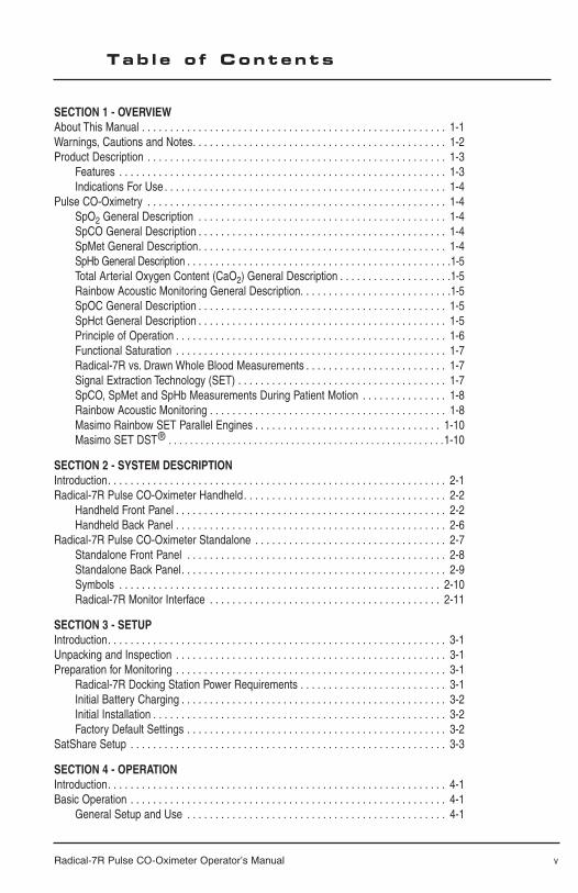
SECTION 1 - OVERVIEWAbout This Manual . . . . . . . . . . . . . . . . . . . . . . . . . . . . . . . . . . . . . . . . . . . . . . . . . . . . . . 1-1Warnings, Cautions and Notes. . . . . . . . . . . . . . . . . . . . . . . . . . . . . . . . . . . . . . . . . . . . . 1-2Product Description . . . . . . . . . . . . . . . . . . . . . . . . . . . . . . . . . . . . . . . . . . . . . . . . . . . . . 1-3
Features . . . . . . . . . . . . . . . . . . . . . . . . . . . . . . . . . . . . . . . . . . . . . . . . . . . . . . . . . . 1-3Indications For Use . . . . . . . . . . . . . . . . . . . . . . . . . . . . . . . . . . . . . . . . . . . . . . . . . . 1-4
Pulse CO-Oximetry . . . . . . . . . . . . . . . . . . . . . . . . . . . . . . . . . . . . . . . . . . . . . . . . . . . . . 1-4SpO2 General Description . . . . . . . . . . . . . . . . . . . . . . . . . . . . . . . . . . . . . . . . . . . . 1-4SpCO General Description . . . . . . . . . . . . . . . . . . . . . . . . . . . . . . . . . . . . . . . . . . . . 1-4SpMet General Description. . . . . . . . . . . . . . . . . . . . . . . . . . . . . . . . . . . . . . . . . . . . 1-4SpHb General Description . . . . . . . . . . . . . . . . . . . . . . . . . . . . . . . . . . . . . . . . . . . . . . .1-5Total Arterial Oxygen Content (CaO2) General Description . . . . . . . . . . . . . . . . . . . .1-5Rainbow Acoustic Monitoring General Description. . . . . . . . . . . . . . . . . . . . . . . . . . .1-5 SpOC General Description . . . . . . . . . . . . . . . . . . . . . . . . . . . . . . . . . . . . . . . . . . . . 1-5SpHct General Description . . . . . . . . . . . . . . . . . . . . . . . . . . . . . . . . . . . . . . . . . . . . 1-5Principle of Operation . . . . . . . . . . . . . . . . . . . . . . . . . . . . . . . . . . . . . . . . . . . . . . . . 1-6Functional Saturation . . . . . . . . . . . . . . . . . . . . . . . . . . . . . . . . . . . . . . . . . . . . . . . . 1-7Radical-7R vs. Drawn Whole Blood Measurements . . . . . . . . . . . . . . . . . . . . . . . . . 1-7Signal Extraction Technology (SET) . . . . . . . . . . . . . . . . . . . . . . . . . . . . . . . . . . . . . 1-7SpCO, SpMet and SpHb Measurements During Patient Motion . . . . . . . . . . . . . . . 1-8Rainbow Acoustic Monitoring . . . . . . . . . . . . . . . . . . . . . . . . . . . . . . . . . . . . . . . . . . 1-8Masimo Rainbow SET Parallel Engines . . . . . . . . . . . . . . . . . . . . . . . . . . . . . . . . . 1-10Masimo SET DST® . . . . . . . . . . . . . . . . . . . . . . . . . . . . . . . . . . . . . . . . . . . . . . . . . . . .1-10
SECTION 2 - SYSTEM DESCRIPTIONIntroduction. . . . . . . . . . . . . . . . . . . . . . . . . . . . . . . . . . . . . . . . . . . . . . . . . . . . . . . . . . . . 2-1Radical-7R Pulse CO-Oximeter Handheld. . . . . . . . . . . . . . . . . . . . . . . . . . . . . . . . . . . . 2-2
Handheld Front Panel . . . . . . . . . . . . . . . . . . . . . . . . . . . . . . . . . . . . . . . . . . . . . . . . 2-2Handheld Back Panel . . . . . . . . . . . . . . . . . . . . . . . . . . . . . . . . . . . . . . . . . . . . . . . . 2-6
Radical-7R Pulse CO-Oximeter Standalone . . . . . . . . . . . . . . . . . . . . . . . . . . . . . . . . . . 2-7Standalone Front Panel . . . . . . . . . . . . . . . . . . . . . . . . . . . . . . . . . . . . . . . . . . . . . . 2-8Standalone Back Panel. . . . . . . . . . . . . . . . . . . . . . . . . . . . . . . . . . . . . . . . . . . . . . . 2-9Symbols . . . . . . . . . . . . . . . . . . . . . . . . . . . . . . . . . . . . . . . . . . . . . . . . . . . . . . . . . 2-10Radical-7R Monitor Interface . . . . . . . . . . . . . . . . . . . . . . . . . . . . . . . . . . . . . . . . . 2-11
SECTION 3 - SETUPIntroduction. . . . . . . . . . . . . . . . . . . . . . . . . . . . . . . . . . . . . . . . . . . . . . . . . . . . . . . . . . . . 3-1Unpacking and Inspection . . . . . . . . . . . . . . . . . . . . . . . . . . . . . . . . . . . . . . . . . . . . . . . . 3-1Preparation for Monitoring . . . . . . . . . . . . . . . . . . . . . . . . . . . . . . . . . . . . . . . . . . . . . . . . 3-1
Radical-7R Docking Station Power Requirements . . . . . . . . . . . . . . . . . . . . . . . . . . 3-1Initial Battery Charging . . . . . . . . . . . . . . . . . . . . . . . . . . . . . . . . . . . . . . . . . . . . . . . 3-2Initial Installation . . . . . . . . . . . . . . . . . . . . . . . . . . . . . . . . . . . . . . . . . . . . . . . . . . . . 3-2Factory Default Settings . . . . . . . . . . . . . . . . . . . . . . . . . . . . . . . . . . . . . . . . . . . . . . 3-2
SatShare Setup . . . . . . . . . . . . . . . . . . . . . . . . . . . . . . . . . . . . . . . . . . . . . . . . . . . . . . . . 3-3
SECTION 4 - OPERATIONIntroduction. . . . . . . . . . . . . . . . . . . . . . . . . . . . . . . . . . . . . . . . . . . . . . . . . . . . . . . . . . . . 4-1Basic Operation . . . . . . . . . . . . . . . . . . . . . . . . . . . . . . . . . . . . . . . . . . . . . . . . . . . . . . . . 4-1
General Setup and Use . . . . . . . . . . . . . . . . . . . . . . . . . . . . . . . . . . . . . . . . . . . . . . 4-1
Tab l e o f Contents
v

Radical-7R Pulse CO-Oximeter Operator’s Manual
Successful Monitoring . . . . . . . . . . . . . . . . . . . . . . . . . . . . . . . . . . . . . . . . . . . . . . . . . . . 4-2Masimo Pulse CO-Oximetry Sensors. . . . . . . . . . . . . . . . . . . . . . . . . . . . . . . . . . . . 4-3Numeric Display - SpO2 . . . . . . . . . . . . . . . . . . . . . . . . . . . . . . . . . . . . . . . . . . . . . . 4-4Numeric Display - Pulse Rate. . . . . . . . . . . . . . . . . . . . . . . . . . . . . . . . . . . . . . . . . . 4-4Numeric Display - RRa . . . . . . . . . . . . . . . . . . . . . . . . . . . . . . . . . . . . . . . . . . . . . . . 4-4Numeric Display - SpCO. . . . . . . . . . . . . . . . . . . . . . . . . . . . . . . . . . . . . . . . . . . . . . 4-4Numeric Display - SpMet . . . . . . . . . . . . . . . . . . . . . . . . . . . . . . . . . . . . . . . . . . . . . 4-4Numeric Display - SpHb . . . . . . . . . . . . . . . . . . . . . . . . . . . . . . . . . . . . . . . . . . . . . . 4-5Numeric Display - SpOC. . . . . . . . . . . . . . . . . . . . . . . . . . . . . . . . . . . . . . . . . . . . . . 4-5Numeric Display - SpHct. . . . . . . . . . . . . . . . . . . . . . . . . . . . . . . . . . . . . . . . . . . . . . 4-5Signal Indication and Quality Indicator (SIQ) . . . . . . . . . . . . . . . . . . . . . . . . . . . . 4-6Signal Indication and Quality Indicator (SIQa) . . . . . . . . . . . . . . . . . . . . . . . . . . . 4-7Respiration Indicator (RI) . . . . . . . . . . . . . . . . . . . . . . . . . . . . . . . . . . . . . . . . . . . . . 4-7Acoustic Respiration Sensor Placement. . . . . . . . . . . . . . . . . . . . . . . . . . . . . . . . . . 4-7Numeric Display - (PI). . . . . . . . . . . . . . . . . . . . . . . . . . . . . . . . . . . . . . . . . . . . . . . . 4-8Pleth Variability Index - (PVI) . . . . . . . . . . . . . . . . . . . . . . . . . . . . . . . . . . . . . . . . . . 4-8Low Perfusion . . . . . . . . . . . . . . . . . . . . . . . . . . . . . . . . . . . . . . . . . . . . . . . . . . . . . . 4-8Actions To Be Taken . . . . . . . . . . . . . . . . . . . . . . . . . . . . . . . . . . . . . . . . . . . . . . . . . 4-8Sensitivity . . . . . . . . . . . . . . . . . . . . . . . . . . . . . . . . . . . . . . . . . . . . . . . . . . . . . . . . . 4-9Touch Key Control Button and Icons. . . . . . . . . . . . . . . . . . . . . . . . . . . . . . . . . . . . 4-10
Traditional User Interface . . . . . . . . . . . . . . . . . . . . . . . . . . . . . . . . . . . . . . . . . . . . . . . . 4-10Navigating the Main Menu . . . . . . . . . . . . . . . . . . . . . . . . . . . . . . . . . . . . . . . . . . . . . . . 4-11
Main Menu Selection . . . . . . . . . . . . . . . . . . . . . . . . . . . . . . . . . . . . . . . . . . . . . . . 4-11Menu Categories. . . . . . . . . . . . . . . . . . . . . . . . . . . . . . . . . . . . . . . . . . . . . . . . . . . 4-11Editing a Parameter/Measurement . . . . . . . . . . . . . . . . . . . . . . . . . . . . . . . . . . . . . 4-11Menu Tree . . . . . . . . . . . . . . . . . . . . . . . . . . . . . . . . . . . . . . . . . . . . . . . . . . . . . . . . 4-12
Alarms . . . . . . . . . . . . . . . . . . . . . . . . . . . . . . . . . . . . . . . . . . . . . . . . . . . . . . . . . . . . . . 4-15General. . . . . . . . . . . . . . . . . . . . . . . . . . . . . . . . . . . . . . . . . . . . . . . . . . . . . . . . . . . . . . 4-17About . . . . . . . . . . . . . . . . . . . . . . . . . . . . . . . . . . . . . . . . . . . . . . . . . . . . . . . . . . . . . . . 4-17Configuration . . . . . . . . . . . . . . . . . . . . . . . . . . . . . . . . . . . . . . . . . . . . . . . . . . . . . . . . . 4-17Output. . . . . . . . . . . . . . . . . . . . . . . . . . . . . . . . . . . . . . . . . . . . . . . . . . . . . . . . . . . . . . . 4-18Satshare Operation . . . . . . . . . . . . . . . . . . . . . . . . . . . . . . . . . . . . . . . . . . . . . . . . . . . . 4-19
SECTION 5 - ALARMS AND MESSAGESAlarm Identification. . . . . . . . . . . . . . . . . . . . . . . . . . . . . . . . . . . . . . . . . . . . . . . . . . . . . . 5-1System Messages . . . . . . . . . . . . . . . . . . . . . . . . . . . . . . . . . . . . . . . . . . . . . . . . . . . . . . 5-2
SECTION 6 - TROUBLESHOOTINGTroubleshooting . . . . . . . . . . . . . . . . . . . . . . . . . . . . . . . . . . . . . . . . . . . . . . . . . . . . . . . . 6-1
SECTION 7 - SPECIFICATIONSRadical-7R Specifications . . . . . . . . . . . . . . . . . . . . . . . . . . . . . . . . . . . . . . . . . . . . . . . . 7-1
Performance . . . . . . . . . . . . . . . . . . . . . . . . . . . . . . . . . . . . . . . . . . . . . . . . . . . . . . . 7-1Accuracy . . . . . . . . . . . . . . . . . . . . . . . . . . . . . . . . . . . . . . . . . . . . . . . . . . . . . . . . . . 7-1Electrical . . . . . . . . . . . . . . . . . . . . . . . . . . . . . . . . . . . . . . . . . . . . . . . . . . . . . . . . . . 7-2Environmental . . . . . . . . . . . . . . . . . . . . . . . . . . . . . . . . . . . . . . . . . . . . . . . . . . . . . . 7-2Physical Characteristics . . . . . . . . . . . . . . . . . . . . . . . . . . . . . . . . . . . . . . . . . . . . . . 7-2
Analog Output/Nurse Call Specifications . . . . . . . . . . . . . . . . . . . . . . . . . . . . . . . . . . . . . 7-4Nurse Call . . . . . . . . . . . . . . . . . . . . . . . . . . . . . . . . . . . . . . . . . . . . . . . . . . . . . . . . . 7-5
Tab l e o f Contents
vi

Radical-7R Pulse CO-Oximeter Operator’s Manual
SECTION 8 - SENSORS & PATIENT CABLESIntroduction. . . . . . . . . . . . . . . . . . . . . . . . . . . . . . . . . . . . . . . . . . . . . . . . . . . . . . . . . . . . 8-1
Selecting a Masimo SET Sensor . . . . . . . . . . . . . . . . . . . . . . . . . . . . . . . . . . . . . . . 8-1Sensor Application Instructions . . . . . . . . . . . . . . . . . . . . . . . . . . . . . . . . . . . . . . . . 8-1
Masimo Sensors. . . . . . . . . . . . . . . . . . . . . . . . . . . . . . . . . . . . . . . . . . . . . . . . . . . . . . . . 8-2Masimo Acoustic Respiration Sensor . . . . . . . . . . . . . . . . . . . . . . . . . . . . . . . . . . . . 8-2Masimo Rainbow Sensors . . . . . . . . . . . . . . . . . . . . . . . . . . . . . . . . . . . . . . . . . . . . 8-2Rainbow Adhesive Sensors . . . . . . . . . . . . . . . . . . . . . . . . . . . . . . . . . . . . . . . . . . . 8-2Rainbow ReSposable Pulse CO-Oximeter Sensor System . . . . . . . . . . . . . . . . . . . 8-2 Rainbow Reusable Sensors . . . . . . . . . . . . . . . . . . . . . . . . . . . . . . . . . . . . . . . . . . . 8-2Rainbow Direct Connect Sensors. . . . . . . . . . . . . . . . . . . . . . . . . . . . . . . . . . . . . . . 8-3Masimo SpO2 Sensors . . . . . . . . . . . . . . . . . . . . . . . . . . . . . . . . . . . . . . . . . . . . . . . 8-3ReSposable Pulse CO-Oximeter Sensor System. . . . . . . . . . . . . . . . . . . . . . . . . . . 8-3 Red Direct Connect Sensors . . . . . . . . . . . . . . . . . . . . . . . . . . . . . . . . . . . . . . . . . . 8-3LNOP® Reusable Sensors . . . . . . . . . . . . . . . . . . . . . . . . . . . . . . . . . . . . . . . . . . . . 8-4LNOP® Adhesive Sensors. . . . . . . . . . . . . . . . . . . . . . . . . . . . . . . . . . . . . . . . . . . . . 8-4LNOPvTM Adhesive Sensors. . . . . . . . . . . . . . . . . . . . . . . . . . . . . . . . . . . . . . . . . . . . . . . .8-4LNOP® Specialty Sensors. . . . . . . . . . . . . . . . . . . . . . . . . . . . . . . . . . . . . . . . . . . . . 8-4M-LNCS™/LNCS® Reusable Sensors . . . . . . . . . . . . . . . . . . . . . . . . . . . . . . . . . . . 8-4M-LNCS™/LNCS® Adhesive Sensors . . . . . . . . . . . . . . . . . . . . . . . . . . . . . . . . . . . 8-5M-LNCS™/LNCS® Specialty Sensors . . . . . . . . . . . . . . . . . . . . . . . . . . . . . . . . . . . 8-5Sensor Accuracy. . . . . . . . . . . . . . . . . . . . . . . . . . . . . . . . . . . . . . . . . . . . . . . . . . . . 8-6Cleaning And Reuse Of Masimo Reusable Sensors and Cables. . . . . . . . . . . . . . . 8-6Reattachment of a Single Use Acoustic Respiration Sensor . . . . . . . . . . . . . . . . . . 8-6 Reattachment of Single Use Adhesive Sensors. . . . . . . . . . . . . . . . . . . . . . . . . . . . 8-6
SECTION 9 - SERVICE AND MAINTENANCEIntroduction. . . . . . . . . . . . . . . . . . . . . . . . . . . . . . . . . . . . . . . . . . . . . . . . . . . . . . . . . . . . 9-1Cleaning . . . . . . . . . . . . . . . . . . . . . . . . . . . . . . . . . . . . . . . . . . . . . . . . . . . . . . . . . . . . . . 9-1Battery Operation and Maintenance . . . . . . . . . . . . . . . . . . . . . . . . . . . . . . . . . . . . . . . . 9-2
Replacing the Batteries. . . . . . . . . . . . . . . . . . . . . . . . . . . . . . . . . . . . . . . . . . . . . . . 9-3Replacing the Fuses . . . . . . . . . . . . . . . . . . . . . . . . . . . . . . . . . . . . . . . . . . . . . . . . . 9-3
Performance Verification. . . . . . . . . . . . . . . . . . . . . . . . . . . . . . . . . . . . . . . . . . . . . . . . . . 9-4Service and Repair. . . . . . . . . . . . . . . . . . . . . . . . . . . . . . . . . . . . . . . . . . . . . . . . . . . . . . 9-6
Repair Policy . . . . . . . . . . . . . . . . . . . . . . . . . . . . . . . . . . . . . . . . . . . . . . . . . . . . . . . 9-6Return Procedure . . . . . . . . . . . . . . . . . . . . . . . . . . . . . . . . . . . . . . . . . . . . . . . . . . . 9-6
Sales & End-User License Agreement. . . . . . . . . . . . . . . . . . . . . . . . . . . . . . . . . . . . . . . 9-8Warranty. . . . . . . . . . . . . . . . . . . . . . . . . . . . . . . . . . . . . . . . . . . . . . . . . . . . . . . . . . . . . . 9-7Exclusions . . . . . . . . . . . . . . . . . . . . . . . . . . . . . . . . . . . . . . . . . . . . . . . . . . . . . . . . . . . . 9-7End-User License Agreement . . . . . . . . . . . . . . . . . . . . . . . . . . . . . . . . . . . . . . . . . . . . . 9-8Restrictions . . . . . . . . . . . . . . . . . . . . . . . . . . . . . . . . . . . . . . . . . . . . . . . . . . . . . . . . . . . 9-8No Implied License . . . . . . . . . . . . . . . . . . . . . . . . . . . . . . . . . . . . . . . . . . . . . . . . . . . . . 9-8Sensors Licensed for Monitoring Use Only . . . . . . . . . . . . . . . . . . . . . . . . . . . . . . . . . . . 9-8
SECTION 10 - PART NUMBERSPart Numbers . . . . . . . . . . . . . . . . . . . . . . . . . . . . . . . . . . . . . . . . . . . . . . . . . . . . . . . . . 10-1
Tab l e o f Contents
vii

Radical-7R Pulse CO-Oximeter Operator’s Manual 1-1
1Overv i ew
About Th is Manua l
This manual explains how to set up and use the Radical-7R Pulse CO-Oximeter containing Masimo Rainbow SET® technology. Important safety information relating to general use of the Pulse CO-Oximeter appears before this introduction. Other important safety information is located throughout the manual where appropriate.Read the entire safety information section before you operate the monitor.
In addition to the safety section, this manual includes the following sections:
SECTION 1 OVERVIEW gives a general description of Radical-7R Pulse CO-Oximeter.
SECTION 2 SYSTEM DESCRIPTION describes the Radical-7R Pulse CO-Oximeter system and its functions and features.
SECTION 3 SETUP describes how to setup the Radical-7R Pulse CO-Oximeter for use.
SECTION 4 OPERATION describes the operation of the Radical-7R Pulse CO-Oximetry system.
SECTION 5 ALARMS AND MESSAGES describes the alarm system messages.
SECTION 6 TROUBLESHOOTING describes troubleshooting information.
SECTION 7 SPECIFICATIONS gives the detailed specifi cations of the Radical-7R Pulse CO-Oximeter.
SECTION 8 SENSORS & PATIENT CABLES outlines how to use and care for Masimo Rainbow SET technology sensors, Masimo Rainbow SET technology patient cables, Masimo Red sensors and Masimo Red patient cables.
SECTION 9 SERVICE AND MAINTENANCE describes how to maintain, service and obtain repair for the Radical-7R Pulse CO-Oximeter.
SECTION 10 PART NUMBERS lists the available Radical-7R Pulse CO-Oximeter accessories.
1-2 Radical-7R Pulse CO-Oximeter Operator’s Manual
1
Warn ings , Caut ions and Notes
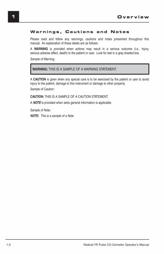
Please read and follow any warnings, cautions and notes presented throughout this manual. An explanation of these labels are as follows:
A WARNING is provided when actions may result in a serious outcome (i.e., injury, serious adverse affect, death) to the patient or user. Look for text in a gray shaded box.
Sample of Warning:
WARNING: THIS IS A SAMPLE OF A WARNING STATEMENT.
A CAUTION is given when any special care is to be exercised by the patient or user to avoid injury to the patient, damage to this instrument or damage to other property.
Sample of Caution:
CAUTION: THIS IS A SAMPLE OF A CAUTION STATEMENT.
A NOTE is provided when extra general information is applicable.
Sample of Note:
NOTE: This is a sample of a Note.
Overv i ew

Radical-7R Pulse CO-Oximeter Operator’s Manual 1-3
1Overv i ew
Product Descr ipt i onThe Radical-7R Pulse CO-Oximeter is a noninvasive, arterial oxygen saturation, total hemoglobin concentration and pulse rate monitor. It can be used as either a Handheld or a Standalone monitor. The Radical-7R Pulse CO-Oximeter features a backlit Liquid Crystal Display (LCD) that continuously displays numeric values for SpO2, SpMet®*, SpCO®*, SpHb®*, SpOC™*, SpHct™, respiration rate (RRa™), pulse rate, Perfusion Index (PI) and Pleth Variability Index (PVI®). It also provides graphical displays for plethysmographic waveform and Signal Identifi cation and Quality Indicator (Signal IQ®). The Radical-7R Pulse CO-Oximeter can be used to interface with a multiparameter patient monitor to provide Masimo SET SpO2 and pulse rate information to that monitor for display.
FEATURESThese features are common to the Radical-7R family:■ Masimo SET is clinically proven to be the highest sensitivity and specifi city pulse
oximeter technology in the world.■ Rainbow technology uses 7+ wavelengths of light to continuously and noninvasively
measure carboxyhemoglobin (SpCO), methemoglobin (SpMet) and total hemoglobin (SpHb), as well as providing a more reliable probe-off detection.
■ Rainbow Acoustic Monitoring uses acoustic monitoring technology to measure and display respiration rate (RRa) while providing the Respiration Indicator (RI) at the sensor site.
■ SIQa displays the confidence level of the Acoustic Respiration measurement signal quality.■ Total Oxygen Content (SpOC™*) provides a calculated measurement of the amount
of oxygen in arterial blood, which may provide useful information about oxygen both dissolved in plasma and combined with hemoglobin.
■ Displays percent hematocrit (%SpHct), the measurement of total red blood cell count divided by total blood volume.
■ Perfusion Index (PI) with trending capability indicates arterial pulse signal strength and may be used as a diagnostic tool during low perfusion.
■ *Pleth Variability Index (PVI) may show changes that refl ect physiologic factors such as vascular tone, circulating blood volume, and intrathoracic pressure excursions.1
■ Accurate on cyanotic infants with congenital heart disease when used with an LNOP® Blue Sensor.
■ Signal IQ waveform for signal identifi cation and quality indication during excessive motion and low signal to noise situations.
■ FastSat® tracks rapid changes in arterial O2 with high fi delity unlike any other pulse oximeter.■ SatShare® interface allows transfer of SpO2 and pulse rate to an existing multiparameter
monitor and allows for the reading of SpCO, SpMet, SpHb and SpOC on adjacent Radical-7R monitor.
■ Detachable portable handheld for patient transport.1 The utility of PVI is unknown at this time and requires further clinical studies. Technical factors that may
affect PVI include probe malposition and patient motion.* Optional parameters/measurements
1-4 Radical-7R Pulse CO-Oximeter Operator’s Manual
1 Overv i ew
INDICATIONS FOR USEThe Radical-7R Pulse CO-Oximeter and accessories are indicated for the continuous noninvasive monitoring of functional oxygen saturation of arterial hemoglobin (SpO2), pulse rate, carboxyhemoglobin saturation (SpCO), methemoglobin saturation (SpMet), total hemoglobin concentration (SpHb), and/or respiratory rate (RRa). The Radical-7R Pulse CO-Oximeter and accessories are indicated for use with adult, pediatric, and neonatal patients during both no motion and motion conditions, and for patients who are well or poorly perfused in hospitals, hospital-type facilities, mobile, and home environments. In addition, the Radical-7R Pulse CO-Oximeter and accessories are indicated to provide the continuous noninvasive monitoring data obtained from the Radical-7R Pulse CO-Oximeter and accessories of functional oxygen saturation of arterial hemoglobin (SpO2) and pulse rate to multi-parameter devices for the display of those devices.
Pu lse CO-Ox imetry
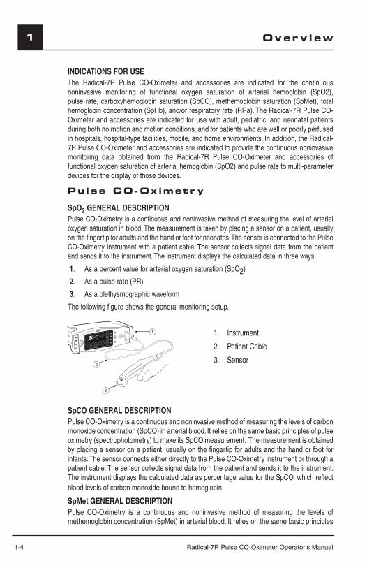
SpO2 GENERAL DESCRIPTIONPulse CO-Oximetry is a continuous and noninvasive method of measuring the level of arterial oxygen saturation in blood. The measurement is taken by placing a sensor on a patient, usually on the fi ngertip for adults and the hand or foot for neonates. The sensor is connected to the Pulse CO-Oximetry instrument with a patient cable. The sensor collects signal data from the patient and sends it to the instrument. The instrument displays the calculated data in three ways:
1. As a percent value for arterial oxygen saturation (SpO2)
2. As a pulse rate (PR)
3. As a plethysmographic waveform
The following fi gure shows the general monitoring setup.
SpHb g/dl
17710.0
13SpOC ml/dl---
---------
3.00
6 20
aa
SpCO GENERAL DESCRIPTIONPulse CO-Oximetry is a continuous and noninvasive method of measuring the levels of carbon monoxide concentration (SpCO) in arterial blood. It relies on the same basic principles of pulse oximetry (spectrophotometry) to make its SpCO measurement. The measurement is obtained by placing a sensor on a patient, usually on the fi ngertip for adults and the hand or foot for infants. The sensor connects either directly to the Pulse CO-Oximetry instrument or through a patient cable. The sensor collects signal data from the patient and sends it to the instrument. The instrument displays the calculated data as percentage value for the SpCO, which refl ect blood levels of carbon monoxide bound to hemoglobin.
SpMet GENERAL DESCRIPTIONPulse CO-Oximetry is a continuous and noninvasive method of measuring the levels of methemoglobin concentration (SpMet) in arterial blood. It relies on the same basic principles
1. Instrument
2. Patient Cable
3. Sensor
Radical-7R Pulse CO-Oximeter Operator’s Manual 1-5
1Overv i ew
of pulse oximetry (spectrophotometry) to make its SpMet measurement. The measurement is obtained by placing a sensor on a patient, usually on the fi ngertip for adults and the hand or foot for infants. The sensor connects either directly to the Pulse CO-Oximetry instrument or through a patient cable. The sensor collects signal data from the patient and sends it to the instrument. The instrument displays the calculated data as percentage value for the SpMet.
SpHb GENERAL DESCRIPTIONPulse CO-Oximetery is a continuous and non-invasive method of measuring the levels of total hemoglobin (SpHb) in arterial blood. It relies on the same principles of pulse oximetry to make the SpHb measurement. The measurement is taken by a sensor capable of measuring SpHb, usually on the fingertip for adult and pediatric patients. The sensor connects directly to the Pulse CO-Oximeter or with a patient cable. The sensor collects signal data from the patient and sends it to the instrument. The instrument displays the calculated data as measurement of total hemoglobin concentration.
TOTAL ARTERIAL OXYGEN CONTENT (CaO2) GENERAL DESCRIPTION 2Oxygen (O2) is carried in the blood in two forms, either dissolved in plasma or combined with hemoglobin. The amount of oxygen in the arterial blood is termed the oxygen content (CaO2) and is measured in units of ml O2/dl blood. One gram of hemoglobin (Hb) can carry 1.34 ml of oxygen, whereas 100 ml of blood plasma may carry approximately 0.3 ml of oxygen. The oxygen content is determined mathematically as:
CaO2 = 1.34 (ml O2/g Hb) x Hb (g/dl) x HbO2 + PaO2 (mm Hg) x (0.3 ml O2/ 100 mm Hg/dl)
Where HbO2 is the fractional arterial oxygen saturation and PaO2 is the partial pressure of arterial oxygen.
For typical PaO2 values, the second part of the above equation [PaO2 (mm Hg) x (0.3 ml O2/ 100 mm Hg/dl] is approximately 0.3 ml/dl. Furthermore, for typical carboxyhemoglobin and methemoglobin levels, the functional saturation (SpO2) as measured by a pulse oximeter is given by:
SpO2 = 1.02 x HbO2
2 Martin, Laurence. All You Really Need to Know to Interpret Arterial Blood Gases, Second Edition. New York: Lippincott Williams & Wilkins, 1999.
RAINBOW ACOUSTIC MONITORING GENERAL DESCRIPTIONRainbow Acoustic Monitoring continuously measures a patient's respiration rate based on airflow sounds generated in the upper airway. The Acoustic Respiration sensor translates airflow sounds generated in the upper airway to an electrical signal that can be processed to produce a respiration rate, measured as breaths per minute.
SpOC GENERAL DESCRIPTION (PULSE CO-OXIMETRY) The above approximations result in the following reduced equation for oxygen content via the Pulse CO-Oximeter:
SpOC (ml/dl*) = 1.31 (ml O2/g Hb) x SpHb (g/dl) x SpO2 + 0.3 ml/dl
* When ml O2/g Hb is multiplied by g/dl of SpHb, the gram unit in the denominator of ml/g cancels the gram unit in the numerator of g/dl resulting in ml/dl (ml of oxygen in one dl of blood) as the unit of measure for SpOC.
SpHct GENERAL DESCRIPTIONHematocrit is the fraction of whole blood volume that consists of red blood cells. In nor-mal conditions, there is a linear relationship between hematocrit and the concentration of hemoglobin. An estimated hematocrit as a percentage may be derived by multiplying
1-6 Radical-7R Pulse CO-Oximeter Operator’s Manual
1 Overv i ew1
the hemoglobin concentration in g/dL times three and dropping the units1,2. The hematocrit measurement is determined mathematically in this monitor as:
%Hct = Hb* g/dL x 2.953
* When Hb concentrations are between 8-17 g/dL.1 Nijboer JMM, van der Horst ICC, Hendriks HGD, Hendrik-Jan ten Duis; Mijsten MWN. Myth or Reality:
Hematocrit and Hemoglobin Differ in Trauma. Journal of TRAUMA Injury, Infection, and Critical Care 2007; 62:1310-1312
2 MS, Weatherall; KM Sherry. An evaluation of the Spuncrit infr-red analyzer for measurement of Haema-tocrit: Clin. Lab. Haem. 1997, 19, 183-186
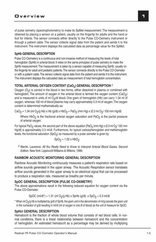
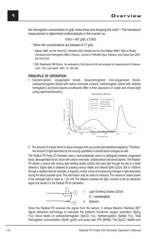
PRINCIPLE OF OPERATION1. Oxyhemoglobin (oxygenated blood), deoxyhemoglobin (non-oxygenated blood),
carboxyhemoglobin (blood with carbon monoxide content), methemoglobin (blood with oxidized hemoglobin) and blood plasma constituents differ in their absorption of visible and infrared light (using spectrophotometry).
Carboxyhemoglobin
Oxyhemoglobin
Methemoglobin
Deoxyhemoglobin
Absorption Spectra
Plasma
Abs
orpt
ion
(1/m
m)
0
0.5
600 800
1.0
1.5
2.0
2.5
3.0
3.5
4.0
1000 1200 1400 1600
Wavelength (nm)
2. The amount of arterial blood in tissue changes with your pulse (photoplethysmography). Therefore, the amount of light absorbed by the varying quantities of arterial blood changes as well.
The Radical-7R Pulse CO-Oximeter uses a multi-wavelength sensor to distinguish between oxygenated blood, deoxygenated blood, blood with carbon monoxide, oxidized blood and blood plasma. The Radical-7R utilizes a sensor with various light-emitting diodes (LEDs) that pass light through the site to a diode (detector). Signal data is obtained by passing various visible and infrared lights (LEDs, 500 to 1400nm) through a capillary bed (for example, a fi ngertip, a hand, a foot) and measuring changes in light absorption during the blood pulsatile cycle. This information may be useful to clinicians. The maximum radiant power of the strongest light is rated at ≤ 25 mW. The detector receives the light, converts it into an electronic signal and sends it to the Radical-7R for calculation.
Once the Radical-7R receives the signal from the sensor, it utilizes Masimo Rainbow SET signal extraction technology to calculate the patient’s functional oxygen saturation (SpO2 (%)), blood levels of carboxyhemoglobin (SpCO (%)), methemoglobin (SpMet (%)), Total Hemoglobin concentration (SpHb (g/dl)) and pulse rate (PR (BPM)). The SpCO, SpMet and
1. Light Emitting Diodes (LEDs)
(7 + wavelengths)
2. Detector2
1
Radical-7R Pulse CO-Oximeter Operator’s Manual 1-7
11Overv i ew
SpHb measurements rely on a multiwavelength calibration equation to quantify the percentage of carbon monoxide and methemoglobin and the concentration of total hemoglobin in arterial blood. In an ambient temperature of 35º C the maximum skin surface temperature has been measured at less than 106º F (41º C), verifi ed by Masimo sensor skin temperature test procedure.
FUNCTIONAL SATURATIONThe Radical-7R is calibrated to measure and display functional saturation (SpO2): the amount of oxyhemoglobin expressed as a percentage of the hemoglobin that is available to transport oxygen. Note that carboxyhemoglobin is not capable of transporting oxygen, but is recognized as oxygenated hemoglobin by conventional pulse oximetry.
Radical-7R vs. DRAWN WHOLE BLOOD MEASUREMENTSWhen SpO2, SpCO, SpMet and SpHb measurements obtained from the Radical-7R (non-invasive) are compared to drawn whole blood (invasive) measurements by blood gas and/or laboratory CO-Oximetry methods, caution should be taken when evaluating and interpreting the results. The blood gas and/or laboratory CO-Oximetry measurements may differ from the SpO2, SpCO, SpMet, SpHb, SpOC, and SpHct measurements of the Radical-7R Pulse CO-Oximeter. In the case of SpO2, different results are usually obtained from the arterial blood gas sample if the calculated measurement is not appropriately corrected for the effects of variables that shift the relationship between the partial pressure of oxygen (PO2) and saturation, such as: pH, temperature, the partial pressure of carbon dioxide (PCO2), 2,3-DPG, and fetal hemoglobin. In the case of SpCO, different results are also expected if concentration of methemoglobin in the blood gas sample is abnormal (greater than 2% for methemoglobin concentration). High levels of bilirubin may cause erroneous SpO2, SpMet, SpCO and SpHb readings. As blood samples are usually taken over a period of 20 seconds (the time it takes to draw the blood) a meaningful comparison can only be achieved if the oxygen saturation, carboxyhemoglobin and methemoglobin concentration of the patient are stable and not changing over the period of time that the blood gas sample is taken. Subsequently, blood gas and laboratory CO-Oximetry measurements of SpO2, SpCO, SpMet, SpHb, SpOC and SpHct may vary with the rapid administration of fluids and in procedures such as dialysis. Additionally, drawn, whole-blood testing can be affected by sample handling methods and time elapsed between blood draw and sample testing.
SIGNAL EXTRACTION TECHNOLOGY (SET) Masimo Signal Extraction Technology's signal processing differs from that of conventional pulse oximeters. Conventional pulse oximeters assume that arterial blood is the only blood moving (pulsating) in the measurement site. During patient motion, however, the venous blood also moves, causing conventional pulse oximeters to read low values, because they cannot distinguish between the arterial and venous blood movement (sometimes referred to as noise). Masimo SET pulse oximetry utilizes parallel engines and adaptive digital fi ltering. Adaptive fi lters are powerful because they are able to adapt to the varying physiologic signals and/or noise and separate them by looking at the whole signal and breaking it down to its fundamental components. The Masimo SET signal processing algorithm, Discrete Saturation Transform® (DST®), in parallel with Fast Saturation Transform® (FST®), reliably identifi es the noise, isolates it and, using adaptive fi lters, cancels it. It then reports the true arterial oxygen saturation for display on the monitor.
1-8 Radical-7R Pulse CO-Oximeter Operator’s Manual
1
SPCO, SPMET, AND SPHB MEASUREMENTS DURING PATIENT MOTION The Radical-7R displays measurements of SpCO, SpMet and SpHb during patient motion. However, because of the changes in the physiological parameters such as blood volume, arterial-venous coupling, etc., that occur during patient motion, the accuracy of such measurements may not be reliable during excessive motion. The measurements for SpCO, SpMet and SpHb display “---” and a message, “LOW SpCO SIQ”, “LOW SpMet SIQ” or “LOW SpHb SIQ”, displays to alert the clinician that the instrument does not have confidence in the value due to poor signal quality caused by excessive motion or other signal interference.
RAINBOW ACOUSTIC MONITORINGRainbow Acoustic Monitoring is a real time, continuous, non-invasive method for measuring respiration rate based on respiratory sounds. Respiratory sounds include sounds related to respiration such as breath sounds (during inspiration and expiration), adventitious sounds, cough sounds, snoring sounds, sneezing sounds, and sounds from the respiratory muscles [1]. These respiratory sounds often have different characteristics depending on the location of recording [2] and they originate in the large airways where air velocity and air turbulence induce vibration in the airway wall. These vibrations are transmitted, for example, through the lung tissue, thoracic wall and trachea to the surface where they may be heard with the aid of a stethoscope, a microphone or more sophisticated devices.
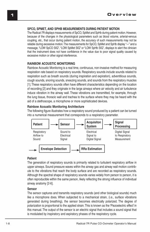
Rainbow Acoustic Monitoring ArchitectureThe following figure illustrates how a respiratory sound produced by a patient can be turned into a numerical measurement that corresponds to a respiratory parameter.
Patient SensorAcquisitonSystem
Signal Processing
Respiratory Airflow to Sound
Sound to Electrical Signal
Electrical Signal to Digital Signal
Digital Signal to Respiratory Measurement
Envelope Detection RRa Estimation
PatientThe generation of respiratory sounds is primarily related to turbulent respiratory airflow in upper airways. Sound pressure waves within the airway gas and airway wall motion contrib-ute to the vibrations that reach the body surface and are recorded as respiratory sounds. Although the spectral shape of respiratory sounds varies widely from person to person, it is often reproducible within the same person, likely reflecting the strong influence of individual airway anatomy [2-6].
SensorThe sensor captures and transmits respiratory sounds (and other biological sounds) much like a microphone does. When subjected to a mechanical strain, (i.e., surface vibrations generated during breathing), the sensor becomes electrically polarized. The degree of polarization is proportional to the applied strain. This is known as the ‘Piezoelectric effect’ in this manual. The output of the sensor is an electric signal that includes a sound signal that is modulated by inspiratory and expiratory phases of the respiratory cycle.
Overv i ew
Radical-7R Pulse CO-Oximeter Operator’s Manual 1-9
1Overv i ew
Acquisition System
The acquisition system converts the electrical signal provided by the sensor into a digital signal. This format allows the signal to be processed by a computing device.
Signal ProcessingThe digital signal produced by the acquisition system is converted into a measurement that corresponds to the respiratory parameter of interest. As shown in the figure on the previous page, this can be performed by, for example, determining the digital signal envelope or out-line which in turn may be utilized to determine the respiratory rate. In this way, a real-time, continuous breath rate parameter can be obtained and displayed on a monitor which, in many cases, may be real-time and continuous.
The respiratory cycle envelope signal processing principle is similar to methods that sample airway gases and subsequently determine a respiratory rate.
[1] A.R.A. Sovijärvi, F. Dalmasso, J. Vanderschool, L.P. Malmberg, G. Righini, S.A.T. Stoneman. Definition of terms for applications of respiratory sounds. Eur Respir Rev 2000; 10:77, 597-610.[2] Z. Moussavi. Fundamentals of respiratory sounds analysis. Synthesis lectures on bio-medical engineering #8. Morgan & Claypool Publishers, 2006.[3] Olsen, et al. Mechanisms of lung sound generation. Semin Respir Med 1985; 6: 171-179.[4] Pastercamp H, Kraman SS, Wodicka GR. Respiratory sounds – Advances beyond the stethoscope. Am J Respir Crit Care Med 1977; 156: 974-987.[5] Gavriely N, Cugell DW. Airflow effects on amplitude and spectral content of normal breath sounds. J Appl Physiol 1996; 80: 5-13.[6] Gavrieli N, Palti Y, Alroy G. Spectral characteristics of normal breath sounds. J Appl Physiol 1981; 50: 307-314.
1-10 Radical-7R Pulse CO-Oximeter Operator’s Manual
1
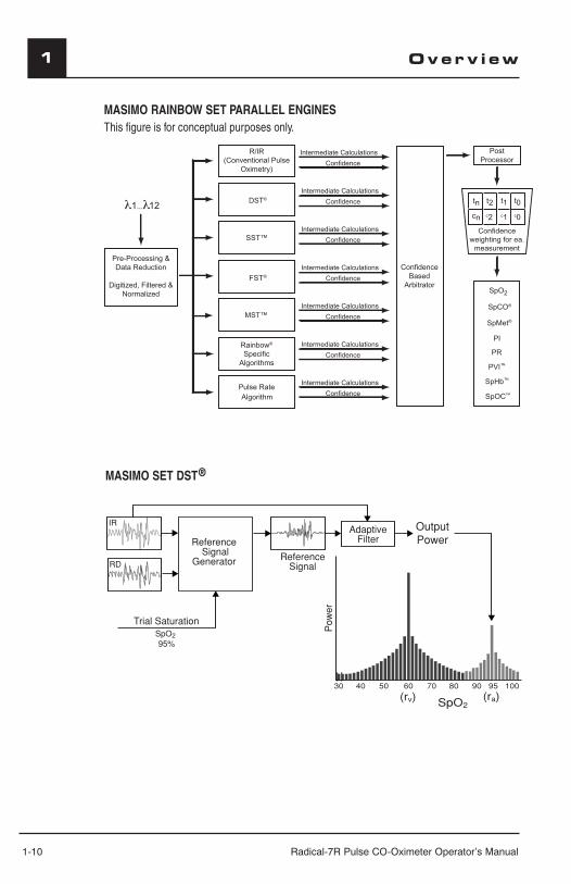
MASIMO SET DST®
Overv i ew
MASIMO RAINBOW SET PARALLEL ENGINESThis fi gure is for conceptual purposes only.
SpOC
12
FST
MST
Radical-7R Pulse CO-Oximeter Operator’s Manual 2-1
2System Descr ipt i on
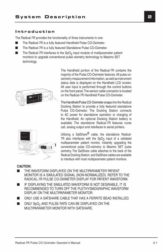
Introduct ionThe Radical-7R provides the functionality of three instruments in one:■ The Radical-7R is a fully featured Handheld Pulse CO-Oximeter.■ The Radical-7R is a fully featured Standalone Pulse CO-Oximeter.■ The Radical-7R interfaces to the SpO2 input module of multiparameter patient
monitors to upgrade conventional pulse oximetry technology to Masimo SET technology.
aa
The Handheld portion of the Radical-7R contains the majority of the Pulse CO-Oximeter features. All pulse co-oximetry measurement information, as well as instrument status data is displayed on the Handheld LCD screen. All user input is performed through the control buttons on the front panel. The sensor cable connector is located on the Radical-7R Handheld Pulse CO-Oximeter.
The Handheld Pulse CO-Oximeter snaps into the Radical Docking Station to provide a fully featured standalone Pulse CO-Oximeter. The Docking Station connects to AC power for standalone operation or charging of the Handheld. An optional Docking Station battery is available. The standalone Radical-7R features nurse call, analog output and interfaces to serial printers.
97
76
SpHb g/dl
17710.0
SpOC
Utilizing a SatShare® cable, the standalone Radical-7R also interfaces with the SpO2 input of a validated multiparameter patient monitor, instantly upgrading the conventional pulse CO-oximetry to Masimo SET pulse oximetry. The SatShare cable attaches to the back of the Radical Docking Station, and SatShare cables are available to interface with most multiparameter patient monitors.
CAUTION: ■ THE WAVEFORM DISPLAYED ON THE MULTIPARAMETER PATIENT
MONITOR IS A SIMULATED SIGNAL (NON-NORMALIZED). REFER TO THE RADICAL-7R PULSE CO-OXIMETER DISPLAY FOR PATIENT WAVEFORM.
■ IF DISPLAYING THE SIMULATED WAVEFORM IS NOT DESIRABLE, IT IS RECOMMENDED TO TURN OFF THE PLETHYSMOGRAPHIC WAVEFORM DISPLAY ON THE MULTIPARAMETER MONITOR.
■ ONLY USE A SATSHARE CABLE THAT HAS A FERRITE BEAD INSTALLED.
■ ONLY SpO2 AND PULSE RATE CAN BE DISPLAYED ON THE MULTIPARAMETER MONITOR WITH SATSHARE.
2-2 Radical-7R Pulse CO-Oximeter Operator’s Manual
2 System Descr ipt i on
Rad ica l -7R Pu lse CO-Ox imeter Handhe ld
The Handheld Radical-7R Pulse CO-Oximeter provides most of the functionality of the Pulse CO-Oximeter. All user input and displays are controlled by this part of the Radical-7R Pulse CO-Oximeter system. The patient cable connects into the connector on the Handheld instrument. The Handheld is battery powered and can be used either as a transport monitor or as a Handheld Pulse CO-Oximeter for spot checks.
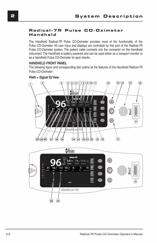
HANDHELD FRONT PANELThe following figure and corresponding text outline all the features of the Handheld Radical-7R Pulse CO-Oximeter:
Pleth + Signal IQ View
SpHb g/dl
177
14
13------
------ SpOC ml/dl
96a
30 29 28
SpHb g/dl
177
14
13------
------ SpOC ml/dl
96a
RI SIQa
332
aaaaaaaaaaaaaaaaaaa
Radical-7R Pulse CO-Oximeter Operator’s Manual 2-3
2System Descr ipt i on
HANDHELD FRONT PANEL (CONTINUED)
1
HANDHELD RELEASE BUTTON
Press down the Handheld Release Button and pull the Handheld instrument off the Docking Station.
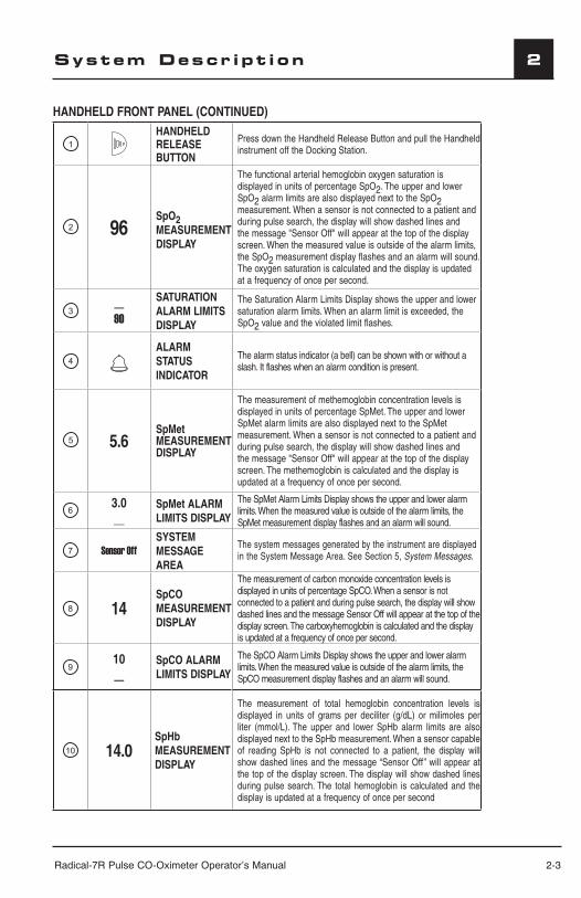
2 96SpO2 MEASUREMENT DISPLAY
The functional arterial hemoglobin oxygen saturation is displayed in units of percentage SpO2. The upper and lower SpO2 alarm limits are also displayed next to the SpO2 measurement. When a sensor is not connected to a patient and during pulse search, the display will show dashed lines and the message "Sensor Off" will appear at the top of the display screen. When the measured value is outside of the alarm limits, the SpO2 measurement display flashes and an alarm will sound. The oxygen saturation is calculated and the display is updated at a frequency of once per second.
3__90
SATURATION ALARM LIMITS DISPLAY
The Saturation Alarm Limits Display shows the upper and lower saturation alarm limits. When an alarm limit is exceeded, the SpO2 value and the violated limit flashes.
4
ALARM STATUS INDICATOR
The alarm status indicator (a bell) can be shown with or without a slash. It flashes when an alarm condition is present.
5 5.6SpMet MEASUREMENT DISPLAY
The measurement of methemoglobin concentration levels is displayed in units of percentage SpMet. The upper and lower SpMet alarm limits are also displayed next to the SpMet measurement. When a sensor is not connected to a patient and during pulse search, the display will show dashed lines and the message "Sensor Off" will appear at the top of the display screen. The methemoglobin is calculated and the display is updated at a frequency of once per second.
63.0__
SpMet ALARM LIMITS DISPLAY
The SpMet Alarm Limits Display shows the upper and lower alarm limits. When the measured value is outside of the alarm limits, the SpMet measurement display flashes and an alarm will sound.
7 Sensor OffSYSTEM MESSAGE AREA
The system messages generated by the instrument are displayed in the System Message Area. See Section 5, System Messages.
8 14SpCO MEASUREMENT DISPLAY
The measurement of carbon monoxide concentration levels is displayed in units of percentage SpCO. When a sensor is not connected to a patient and during pulse search, the display will show dashed lines and the message Sensor Off will appear at the top of the display screen. The carboxyhemoglobin is calculated and the display is updated at a frequency of once per second.
910__
SpCO ALARM LIMITS DISPLAY
The SpCO Alarm Limits Display shows the upper and lower alarm limits. When the measured value is outside of the alarm limits, the SpCO measurement display flashes and an alarm will sound.
10 14.0SpHbMEASUREMENT DISPLAY
The measurement of total hemoglobin concentration levels is displayed in units of grams per deciliter (g/dL) or milimoles per liter (mmol/L). The upper and lower SpHb alarm limits are also displayed next to the SpHb measurement. When a sensor capable of reading SpHb is not connected to a patient, the display will show dashed lines and the message “Sensor Off” will appear at the top of the display screen. The display will show dashed lines during pulse search. The total hemoglobin is calculated and the display is updated at a frequency of once per second
2-4 Radical-7R Pulse CO-Oximeter Operator’s Manual
2 System Descr ipt i on
HANDHELD FRONT PANEL (CONTINUED)
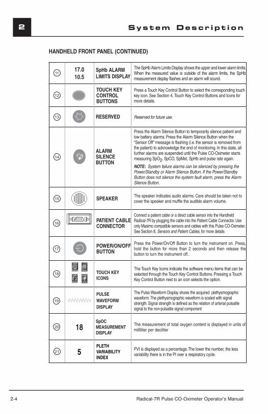
1117.010.5
SpHb ALARM LIMITS DISPLAY
The SpHb Alarm Limits Display shows the upper and lower alarm limits. When the measured value is outside of the alarm limits, the SpHb measurement display flashes and an alarm will sound.
12
TOUCH KEY CONTROL BUTTONS
Press a Touch Key Control Button to select the corresponding touch key icon. See Section 4, Touch Key Control Buttons and Icons for more details.
13 RESERVED Reserved for future use.
14
ALARM SILENCE BUTTON
Press the Alarm Silence Button to temporarily silence patient and low battery alarms. Press the Alarm Silence Button when the “Sensor Off” message is flashing (i.e. the sensor is removed from the patient) to acknowledge the end of monitoring. In this state, all further alarms are suspended until the Pulse CO-Oximeter starts measuring SpO2, SpCO, SpMet, SpHb and pulse rate again.
NOTE: System failure alarms can be silenced by pressing the Power/Standby or Alarm Silence Button. If the Power/Standby Button does not silence the system fault alarm, press the Alarm Silence Button.
15 SPEAKER The speaker indicates audio alarms. Care should be taken not to cover the speaker and muffle the audible alarm volume.
16PATIENT CABLE CONNECTOR
Connect a patient cable or a direct cable sensor into the Handheld Radical-7R by plugging the cable into the Patient Cable Connector. Use only Masimo compatible sensors and cables with this Pulse CO-Oximeter. See Section 8, Sensors and Patient Cables, for more details
17POWER/ON/OFF BUTTON
Press the Power/On/Off Button to turn the instrument on. Press, hold the button for more than 2 seconds and then release the button to turn the instrument off..
18 TOUCH KEY ICONS
The Touch Key Icons indicate the software menu items that can be selected through the Touch Key Control Buttons. Pressing a Touch Key Control Button next to an icon selects the option.
19
PULSE WAVEFORM DISPLAY
The Pulse Waveform Display shows the acquired plethysmographic waveform. The plethysmographic waveform is scaled with signal strength. Signal strength is defined as the relation of arterial pulsatile signal to the non-pulsatile signal component
20 18SpOCMEASUREMENT DISPLAY
The measurement of total oxygen content is displayed in units of milliliter per deciliter
21 5PLETH VARIABILITY INDEX
PVI is displayed as a percentage. The lower the number, the less variability there is in the PI over a respiratory cycle.
Radical-7R Pulse CO-Oximeter Operator’s Manual 2-5
2System Descr ipt i on
HANDHELD FRONT PANEL (CONTINUED)
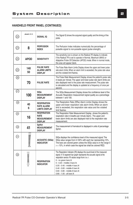
22 SIGNAL IQ The Signal IQ shows the acquired signal quality and the timing of the pulse.
23 8 PERFUSION INDEX
The Perfusion Index indicates numerically the percentage of pulsatile signal to non-pulsatile signal (pulse strength).
24 APOD SENSITIVITY
The sensitivity icon is shown on the Radical-7R display to indicate if the Radical 7R is set to operate in Normal, Maximum (MAX) or Adapative Probe Off Detection (APOD) mode. When in normal mode, this area will appear blank.
2514050
PULSE RATE ALARM LIMITS DISPLAY
The Pulse Rate Alarm Limits Display shows the upper and lower pulse rate alarm limits. When an alarm limit is exceeded, the pulse rate value and the violated limit flashes.
26
70 PULSE RATE
The Pulse Rate Measurement Display shows the patient’s pulse rate in beats per minute. The upper and lower pulse rate alarm limits are also displayed next to the pulse rate measurement. The pulse rate is calculated and the display is updated at a frequency of once per second.
27
100SIQa MEASUREMENT DISPLAY
The SIQa Measurement Display shows the confidence level of the Acoustic Respiration measurement signal quality as a percentage between 1 and 100.
28
406
RESPIRATION RATE ALARM LIMITS DISPLAY
The Respiration Rate (RRa) Alarm Limits Display shows the upper and lower respiration rate alarm limits. When an alarm limit is exceeded, the respiration rate value and the violated limit flashes.
29
16RESPIRATION RATE MEASUREMENT DISPLAY
The Respiration Rate Measurement Dsiplay shows the patient's respiration rate in breaths per minute (bpm). The upper and lower alarm limits are also displayed next to the respiration rate measurement.
30 41SpHct MEASUREMENT DISPLAY
The measurement of hematocrit is displayed in units of percentage SpHct .
31
SIQa
ACOUSTIC (SIQa) INDICATOR
SIQa displays the confidence level of the measured signal. The SIQa value ranges from 0-100% with each bar representing 10%. The bars are colored green unless the SIQa value is in the range 0 > = 10%, in which case the signal bar shall be colored RED.
32
RI
RESPIRATION INDICATOR
The Respiration Indicator (RI) displays the sound level of the measured signal. A 10 segment bar graph represents the acoustic signal at the respiration sensor. RI values range from 0 to 1.0 - no green bars lit 0 - 0.20 - middle 2 bars lit.0.20 - 0.40 - middle 4 bars lit0.40 - 0.60 - middle 6 bars lit0.60 - 0.80 - middle 8 bars lit0.80 - 1.00 - all bars lit

2-6 Radical-7R Pulse CO-Oximeter Operator’s Manual
2 System Descr ipt i on
HANDHELD BACK PANELThe Handheld back panel features the interconnection to the Docking Station, an accessory mount for the pole clamp accessory and access to the Handheld battery pack.
1
DOCKING STATION CONNECTOR
The Radical-7R Handheld interfaces with the Docking Station through this connector.
2
POLE CLAMP ACCESSORY HOLDER
The optional Pole Clamp accessory attaches to this holder. See the Directions for Use of the Pole Clamp accessory for attachment instructions.
BATTERY PACKThe Radical-7R Handheld is powered by a NiMH battery located in this compartment. For battery care and replacement please see Section 9, Replacing the Batteries.
1 2 3
HANDHELD FRONT PANEL (CONTINUED)
Radical-7R Pulse CO-Oximeter Operator’s Manual 2-7
2System Descr ipt i on
Rad ica l -7R Pu lse CO-Ox imeter Standa lone
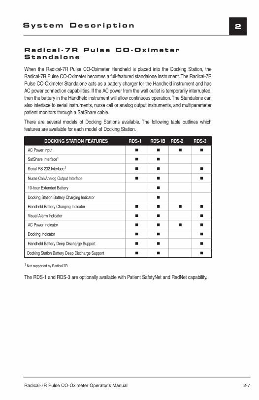
When the Radical-7R Pulse CO-Oximeter Handheld is placed into the Docking Station, the Radical-7R Pulse CO-Oximeter becomes a full-featured standalone instrument. The Radical-7R Pulse CO-Oximeter Standalone acts as a battery charger for the Handheld instrument and has AC power connection capabilities. If the AC power from the wall outlet is temporarily interrupted, then the battery in the Handheld instrument will allow continuous operation. The Standalone can also interface to serial instruments, nurse call or analog output instruments, and multiparameter patient monitors through a SatShare cable.
There are several models of Docking Stations available. The following table outlines which features are available for each model of Docking Station.
DOCKING STATION FEATURES RDS-1 RDS-1B RDS-2 RDS-3
AC Power Input
SatShare Interface1
Serial RS-232 Interface1
Nurse Call/Analog Output Interface
10-hour Extended Battery
Docking Station Battery Charging Indicator
Handheld Battery Charging Indicator
Visual Alarm Indicator
AC Power Indicator
Docking Indicator
Handheld Battery Deep Discharge Support
Docking Station Battery Deep Discharge Support
1 Not supported by Radical-7R
The RDS-1 and RDS-3 are optionally available with Patient SafetyNet and RadNet capability.
2-8 Radical-7R Pulse CO-Oximeter Operator’s Manual
2 System Descr ipt i on
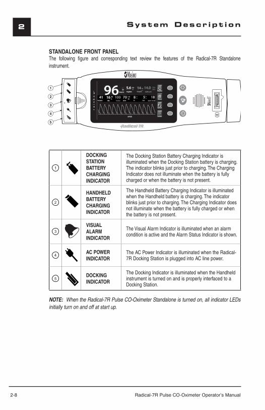
STANDALONE FRONT PANELThe following figure and corresponding text review the features of the Radical-7R Standalone instrument.
1
DOCKING STATION BATTERY CHARGING INDICATOR
The Docking Station Battery Charging Indicator is illuminated when the Docking Station battery is charging. The indicator blinks just prior to charging. The Charging Indicator does not illuminate when the battery is fully charged or when the battery is not present.
2
HANDHELD BATTERY CHARGING INDICATOR
The Handheld Battery Charging Indicator is illuminated when the Handheld battery is charging. The indicator blinks just prior to charging. The Charging Indicator does not illuminate when the battery is fully charged or when the battery is not present.
3
VISUAL ALARM INDICATOR
The Visual Alarm Indicator is illuminated when an alarm condition is active and the Alarm Status Indicator is shown.
4AC POWER INDICATOR
The AC Power Indicator is illuminated when the Radical-7R Docking Station is plugged into AC line power.
5DOCKING INDICATOR
The Docking Indicator is illuminated when the Handheld instrument is turned on and is properly interfaced to a Docking Station.
NOTE: When the Radical-7R Pulse CO-Oximeter Standalone is turned on, all indicator LEDs initially turn on and off at start up.
17710.0
13 SpOC ml/dl
SpHb g/dl
------
------
aa
Radical-7R Pulse CO-Oximeter Operator’s Manual 2-9
2System Descr ipt i on
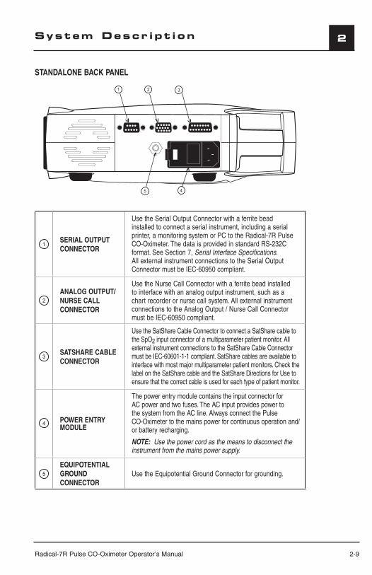
STANDALONE BACK PANEL
1SERIAL OUTPUT CONNECTOR
Use the Serial Output Connector with a ferrite bead installed to connect a serial instrument, including a serial printer, a monitoring system or PC to the Radical-7R Pulse CO-Oximeter. The data is provided in standard RS-232C format. See Section 7, Serial Interface Specifications. All external instrument connections to the Serial Output Connector must be IEC-60950 compliant.
2
ANALOG OUTPUT/NURSE CALL CONNECTOR
Use the Nurse Call Connector with a ferrite bead installed to interface with an analog output instrument, such as a chart recorder or nurse call system. All external instrument connections to the Analog Output / Nurse Call Connector must be IEC-60950 compliant.
3SATSHARE CABLE CONNECTOR
Use the SatShare Cable Connector to connect a SatShare cable to the SpO2 input connector of a multiparameter patient monitor. All external instrument connections to the SatShare Cable Connector must be IEC-60601-1-1 compliant. SatShare cables are available to interface with most major multiparameter patient monitors. Check the label on the SatShare cable and the SatShare Directions for Use to ensure that the correct cable is used for each type of patient monitor.
4POWER ENTRY MODULE
The power entry module contains the input connector for AC power and two fuses. The AC input provides power to the system from the AC line. Always connect the Pulse CO-Oximeter to the mains power for continuous operation and/or battery recharging.
NOTE: Use the power cord as the means to disconnect the instrument from the mains power supply.
5
EQUIPOTENTIAL GROUND CONNECTOR
Use the Equipotential Ground Connector for grounding.
1 2 3
45
2-10 Radical-7R Pulse CO-Oximeter Operator’s Manual
2 System Descr ipt i on
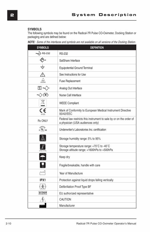
SYMBOLSThe following symbols may be found on the Radical-7R Pulse CO-Oximeter, Docking Station or packaging and are defined below:
NOTE: Some of the interfaces and symbols are not available on all versions of the Docking Station.
SYMBOLS DEFINITION
RS-232
SatShare Interface
Equipotential Ground Terminal
See Instructions for Use
Fuse Replacement
Analog Out Interface
Nurse Call Interface
WEEE Compliant
Mark of Conformity to European Medical Instrument Directive 93/42/EEC
Rx ONLYFederal law restricts this instrument to sale by or on the order of a physician (USA audiences only)
Underwriter's Laboratories Inc. certifi cation
5%-95% RHStorage humidity range: 5% to 95%
-40 C
+70 C
+1060 hPa - +500 hPa795 mmHg - 375 mmHg
Storage temperature range: +70˚C to -40˚CStorage altitude range: +1600hPa to +500hPa
Keep dry
Fragile/breakable, handle with care
Year of Manufacture
IPX1 Protection against liquid drops falling vertically
Defi brillation Proof Type BF
EC REP EU authorized representative
CAUTION
Manufacturer
Radical-7R Pulse CO-Oximeter Operator’s Manual 2-11
2
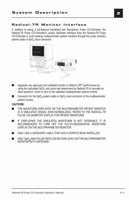
Rad ica l -7R Mon i tor I n ter faceIn addition to being a full-featured Handheld and Standalone Pulse CO-Oximeter, the Radical-7R Pulse CO-Oximeter’s unique SatShare interface links the Radical-7R Pulse CO-Oximeter to most existing multiparameter patient monitors through the pulse oximetry patient cable or SpO2 input connector.
97
76
SpHb g/dl
17710.0
SpOC
■ Upgrades any approved and validated monitor to Masimo SET performance by using the calculated SpO2 and pulse rate determined by Radical-7R to simulate an ideal waveform, which is sent to the validated multiparameter patient monitor.
■ Connects into the SpO2 patient cable or SpO2 input connector of the multiparameter patient monitor.
CAUTIONS:
■ THE WAVEFORM DISPLAYED ON THE MULTIPARAMETER PATIENT MONITOR IS A SIMULATED SIGNAL (NON-NORMALIZED). REFER TO THE RADICAL-7R PULSE CO-OXIMETER DISPLAY FOR PATIENT WAVEFORM.
■ IF DISPLAYING THE SIMULATED WAVEFORM IS NOT DESIRABLE, IT IS RECOMMENDED TO TURN OFF THE PLETHYSMOGRAPHIC WAVEFORM DISPLAY ON THE MULTIPARAMETER MONITOR.
■ ONLY USE A SATSHARE CABLE THAT HAS A FERRITE BEAD INSTALLED.
■ ONLY SpO2 AND PULSE RATE CAN BE DISPLAYED ON THE MULTIPARAMETER MONITOR WITH SATSHARE.
System Descr ipt i on

Radical-7R Pulse CO-Oximeter Operator’s Manual 3-1
3
Introduct ion
Before the Radical-7R Pulse CO-Oximeter can be used in a clinical setting, it needs to be inspected, properly setup and the batteries need to be fully charged.
Unpack ing and I nspect ion
Remove the instrument from the shipping carton and examine it for signs of shipping damage. Check all materials against the packing list. Save all packing materials, invoice and bill of lading. These may be required to process a claim with the carrier.
If anything is missing or damaged, contact the Technical Service Department. The contact address and phone numbers are listed in Section 9, Service and Repair.
Preparat ion for Mon i tor ing
The following sections of the manual describe the preparation, set-up and initial installation of the Radical-7R Pulse CO-Oximeter.
RADICAL-7R DOCKING STATION POWER REQUIREMENTSAlways use a hospital grade, AC power cable to connect the Radical-7R Pulse CO-Oximeter to an AC power source. Do not connect the Radical-7R Docking Station to an AC outlet controlled by a switch because the power to the instrument may be inadvertently switched off.
Verify the AC power voltage and line frequency before use. Verify that the power source can provide adequate power rating as indicated on the rear panel of the Radical-7R Docking Station.
The Radical-7R Pulse CO-Oximeter is designed to operate on 100 to 240VAC, 47-63 Hz. The instrument is rated at 55 VA max.
Connect a hospital grade power cable to the power entry module of the Radical-7R instrument (IEC-320 connector type at the instrument). Connect the power cable to an AC power source. Ensure that the instrument is adequately powered by verifying that the AC power indicator on the Docking Station is illuminated.
CAUTION:
■ DO NOT UNDER ANY CIRCUMSTANCES REMOVE THE GROUNDING CONDUCTOR FROM THE POWER PLUG.
■ DO NOT USE EXTENSION CORDS OR ADAPTERS OF ANY TYPE. THE POWER CORD AND PLUG MUST BE INTACT AND UNDAMAGED.
■ USE THE POWER CORD AS THE MEANS TO DISCONNECT THE INSTRUMENT FROM THE AC POWER AT THE WALL OUTLET.
■ IF THERE IS ANY DOUBT ABOUT THE INTEGRITY OF THE PROTECTIVE EARTH CONDUCTOR ARRANGEMENT, OPERATE THE PULSE CO-OXIMETER ON INTERNAL BATTERY POWER UNTIL THE AC POWER SUPPLY PROTECTIVE CONDUCTOR IS FULLY FUNCTIONAL.
■ TO ENSURE PATIENT ELECTRICAL ISOLATION, CONNECT ONLY TO OTHER EQUIPMENT WITH ELECTRICALLY ISOLATED CIRCUITS.
■ DO NOT CONNECT TO AN ELECTRICAL OUTLET CONTROLLED BY A WALL SWITCH OR DIMMER.
Setup
3-2 Radical-7R Pulse CO-Oximeter Operator’s Manual
3
INITIAL BATTERY CHARGINGBefore use, the Radical-7R Pulse CO-Oximeter Handheld battery and the optional Docking Station battery need to be fully charged.
To charge the batteries:
1. Attach the Handheld instrument to the Docking Station.
2. Plug in the AC power cord to power entry module. Make sure it is securely plugged in.
3. Plug the AC power cord into an AC power source.
4. Verify that the batteries are charging.
The battery charging LED indicators on the Docking Station flash prior to charging and remain illuminated while the batteries are charging.
Refer to Section 9, Battery Operation and Maintenance, for proper battery charging.
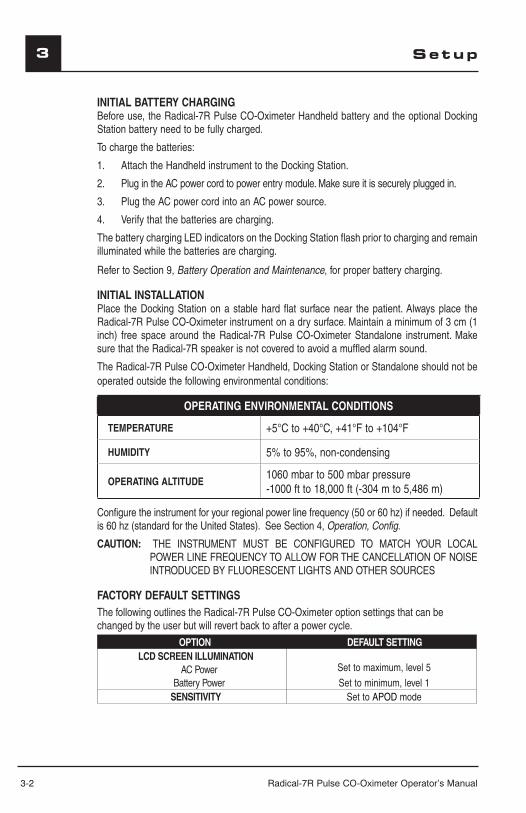
INITIAL INSTALLATIONPlace the Docking Station on a stable hard flat surface near the patient. Always place the Radical-7R Pulse CO-Oximeter instrument on a dry surface. Maintain a minimum of 3 cm (1 inch) free space around the Radical-7R Pulse CO-Oximeter Standalone instrument. Make sure that the Radical-7R speaker is not covered to avoid a muffled alarm sound.
The Radical-7R Pulse CO-Oximeter Handheld, Docking Station or Standalone should not be operated outside the following environmental conditions:
OPERATING ENVIRONMENTAL CONDITIONS
TEMPERATURE +5°C to +40°C, +41°F to +104°F
HUMIDITY 5% to 95%, non-condensing
OPERATING ALTITUDE1060 mbar to 500 mbar pressure-1000 ft to 18,000 ft (-304 m to 5,486 m)
Configure the instrument for your regional power line frequency (50 or 60 hz) if needed. Default is 60 hz (standard for the United States). See Section 4, Operation, Config.
CAUTION: THE INSTRUMENT MUST BE CONFIGURED TO MATCH YOUR LOCAL POWER LINE FREQUENCY TO ALLOW FOR THE CANCELLATION OF NOISE INTRODUCED BY FLUORESCENT LIGHTS AND OTHER SOURCES
FACTORY DEFAULT SETTINGSThe following outlines the Radical-7R Pulse CO-Oximeter option settings that can be changed by the user but will revert back to after a power cycle.
OPTION DEFAULT SETTINGLCD SCREEN ILLUMINATION
AC PowerBattery Power
Set to maximum, level 5
Set to minimum, level 1SENSITIVITY Set to APOD mode
Setup
Radical-7R Pulse CO-Oximeter Operator’s Manual 3-3
3Setup
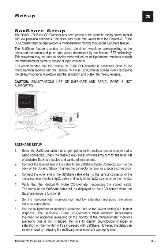
SatShare SetupThe Radical-7R Pulse CO-Oximeter has been proven to be accurate during patient motion and low perfusion conditions. Saturation and pulse rate values from the Radical-7R Pulse CO-Oximeter may be displayed on a multiparameter monitor through the SatShare feature.
The SatShare feature provides an ideal, simulated waveform corresponding to the measured saturation and pulse rate values determined by the Masimo SET technology. This waveform may be used to display these values on multiparameter monitors through the multiparameter oximetry sensor or input connector.It is recommended that the Radical-7R Pulse CO-Oximeter is positioned close to the multiparameter monitor with the Radical-7R Pulse CO-Oximeter screen visibly displaying the plethysmographic waveform and the saturation and pulse rate measurements.
CAUTION: SIMULTANEOUS USE OF SATSHARE AND SERIAL PORT IS NOT SUPPORTED.
SATSHARE SETUP
1. Select the SatShare cable that is appropriate for the multiparameter monitor that is being connected. Check the Masimo web site at www.masimo.com for the latest list of available SatShare cables and validated instruments.
2. Connect the labeled end of the cable to the SatShare Cable Connector port on the back of the Docking Station. Tighten the connector screws for a secure connection.
3. Connect the other end of the SatShare cable either to the sensor connector of the multiparameter monitor’s SpO2 cable or directly to the SpO2 connector on the monitor.
4. Verify that the Radical-7R Pulse CO-Oximeter recognizes the correct cable. The name of the SatShare cable will be displayed on the LCD screen when the SatShare mode is functional.
5. Set the multiparameter monitor’s high and low saturation and pulse rate alarm limits as appropriate.
6. Set the multiparameter monitor’s averaging time to the lowest setting (i.e. fastest response). The Radical-7R Pulse CO-Oximeter’s ideal waveform necessitates the need for additional averaging by the monitor. If the multiparameter monitor’s averaging time is not changed, the time to display physiological changes in saturation on the monitor will be increased with SatShare. However, the delay can be minimized by reducing the multiparameter monitor’s averaging time.
97
76
SpHb g/dl
17710.0
SpOC
3-4 Radical-7R Pulse CO-Oximeter Operator’s Manual
3
7. While in the SatShare mode, if there are any significant discrepancies between the readings from the Radical-7R Pulse CO-Oximeter and those on the monitor displaying the values obtained from SatShare, the values reported by the Radical-7R Pulse CO-Oximeter are to be considered the correct values.
8. To use the Radical-7R Pulse CO-Oximeter with SatShare while it is not connected to AC power, set the Power Save parameter in the General menu to “No” and refer to Section 4 Operation. Please note that if the Radical-7R Pulse CO-Oximeter is used in this mode, the length of time the Radical-7R Pulse CO-Oximeter can operate on battery power will be significantly diminished.
9. Set the SatShare Numbers and the Interface Alarms SpO2/pulse rate parameters in the General menu according to customer preference.
When Rainbow parameters (SpCO, SpMet, SpHb, etc.) are configured, Interface Alarms "SpO2/BPM" can be set to “Yes” or “No”. The “Yes” setting allows SpO2 and pulse rate audible alarms at both the Radical-7R and the interfaced system. The “No” setting mutes the SpO2 and pulse rate audible alarms at the Radical-7R while allowing SpO2 and pulse rate audible alarm alerts at the interfaced system. The “No” setting prevents both systems (Radical-7R and interfaced system) from producing audible alarms at the same time. See section 4: General.
NOTE: The Radical-7R reverts to Interface Alarm "SpO2/BPM" “Yes” during power interruptions or when the SatShare connection is lost or the device becomes separated from the docking station. This ensures that the Radical-7R provides audible alarms for SpO2 and pulse rate when the connection to the interfaced system becomes compromised.
10. If displaying the simulated waveform is not desirable, it is recommended to turn off the plethysmographic waveform display of the multiparameter patient monitor.
SATSHARE SIGNALS ARE IDEAL SIMULATED WAVEFORMS CORRESPONDING TO THE CALCULATED SATURATION AND PULSE RATE VALUES AND DO NOT CONTAIN ALL OF THE INFORMATION CONTAINED IN PHYSIOLOGICAL WAVEFORMS. THE MULTIPARAMETER PATIENT MONITOR TRANSLATES THESE SIGNALS INTO SATURATION AND PULSE RATE VALUES.
DURING SATSHARE OPERATION, THE AUDIBLE ALARMS MAY BE MUTED ON THE RADICAL-7R PULSE CO-OXIMETER. WHEN THE AUDIBLE ALARM IS MUTED (INDICATED BY THE BELL WITH A SLASH THROUGH IT) ON THE RADICAL-7R PULSE CO-OXIMETER, USE THE MULTI-PARAMETER MONITOR FOR AUDIBLE ALARM INDICATION.
DURING SATSHARE OPERATION DO NOT USE THE PLETHYSMOGRAPHIC WAVEFORM DISPLAY ON THE MULTIPARAMETER MONITOR FOR DIAGNOSTIC PURPOSES. INSTEAD, USE THE PLETHYSMOGRAPHIC WAVEFORM DISPLAYED ON THE RADICAL-7R PULSE CO-OXIMETER SCREEN
TO AVOID EXCESSIVE BATTERY DISCHARGING, DO NOT CONNECT ANY EQUIPMENT TO THE SATSHARE CONNECTOR UNLESS THE RADICAL-7R PULSE CO-OXIMETER IS CONNECTED TO THE AC MAINS POWER SUPPLY.
ONLY USE A SATSHARE CABLE THAT HAS A FERRITE BEAD INSTALLED.
ONLY SpO2 AND PULSE RATE CAN BE DISPLAYED ON THE MULTIPARAMETER MONITOR WITH SATSHARE.
Setup
Radical-7R Pulse CO-Oximeter Operator’s Manual 3-5
3
THE RADICAL-7R REVERTS TO INTERFACE ALARM SpO2/BPM "YES" DURING POWER INTERRUPTIONS OR WHEN THE SATSHARE CONNECTION IS LOST OR THE INSTRUMENT BECOMES SEPARATED FROM THE DOCKING STATION. THIS ENSURES THAT THE RADICAL-7R PROVIDES AUDIBLE ALARMS FOR SpO2 AND PULSE RATE WHEN THE CONNECTION TO THE INTERFACED SYSTEM BECOMES COMPROMISED.
Setup
Radical-7R Pulse CO-Oximeter Operator’s Manual 4-1
4Operat ion
Introduct ionTo operate the Radical-7R Pulse CO-Oximeter effectively, the instrument must be set up properly and the operator must: Know how the Pulse CO-Oximeter derives its readings (see Section 1, Pulse CO-Oximetry). Be familiar with its controls, components and operation. Understand its status and alarm messages (see Section 5, Alarm Identification, System
Messages and Section 6, Troubleshooting).
Bas ic Operat ionGENERAL SETUP AND USE
1. Inspect the Pulse CO-Oximeter case for damage.2. Connect a patient cable, Dual Rainbow Cable or a direct cable sensor to the Patient
Cable Connector of the Radical-7R Pulse CO-Oximeter. Make sure it is a firm connection and the cable is not twisted, sliced or frayed.
3. If utilizing the Standalone setup, ensure that the power cord is plugged into the Power Cable Connector of the Docking Station and into the AC power.
4. If utilizing a patient cable or Dual Rainbow Cable, select a sensor that is compatible with the Pulse CO-Oximeter before connecting it to the patient cable or instrument. See section 8, Sensors and Patient Cables. If using a single patient adhesive or disposable sensor, check that the emitter (red light) and the detector are properly aligned. Remove any substances that may interfere with the transmission of light between the sensor’s light source and detector. If using an Acoustic Respiration sensor, ensure that the patient's neck area is clean and dry.
5. Attach the sensor to the patient. Refer to the Directions for Use of the sensor.6. Connect the sensor to the instrument (or patient cable) with the logos lining up; make sure
it is a firm connection.7. Press the Power/Standby button to turn the Pulse CO-Oximeter on.8. Make sure the display window is free of alarm and system failure messages (see Section
5, Alarms and Messages).9. On the display, verify:
The high and low alarm limits for SpO2, RRa, SpMet, SpCO, SpHb, PI, PVI, and pulse rate. The readings for SpO2, RRa, SpMet, SpCO, SpHb, SpOC, SpHct, PI, PVI, and pulse rate.
NOTE: “- - -” initially shows in the numeric display fields for all the parameters/measurements when the Radical-7R is turned on. As the system starts monitoring, the numeric display fields update (refresh). The numeric display fields for the parameters/measurements begin to show numbers during the refresh cycles even though the numbers have not stabilized; during this period, the measurement label will flash to indicate that the measurement value is being processed. When the flashing stops, the number has stabilized. In the case of SpHb and PVI, the numeric value will be displayed upon initial stabilization of the number, and the parameter label will continue to flash for an additional processing period to reach optimal confidence.
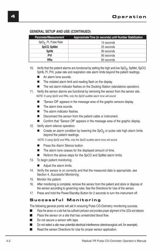
4-2 Radical-7R Pulse CO-Oximeter Operator’s Manual
4
GENERAL SETUP AND USE (CONTINUED)
Parameter/Measurement Approximate Time (in seconds) until Number StabilizationSpO2, PI, Pulse Rate 15 seconds
SpCO, SpMet 25 secondsSpHb 90 secondsPVI 90 secondsRRa 60 seconds
10. Verify that the patient alarms are functional by setting the high and low SpO2, SpMet, SpCO, SpHb, PI, PVI, pulse rate and respiration rate alarm limits beyond the patient readings. An alarm tone sounds. The violated alarm limit and reading flash on the display. The red alarm indicator flashes on the Docking Station (standalone operation).
11. Verify the sensor alarms are functional by removing the sensor from the sensor site. NOTE: If using SpO2 and RRa, only the SpO2 audible alarm tone will sound.
"Sensor Off" appears in the message area of the graphic sensors display. The alarm tone sounds. The alarm indicator flashes. Disconnect the sensor from the patient cable or instrument. Confirm that "Sensor Off" appears in the message area of the graphic display.
12. Verify alarm silence operation. Create an alarm condition by lowering the SpO2 or pulse rate high alarm limits
beyond the patient readings. NOTE: If using SpO2 and RRa, only the SpO2 audible alarm tone will sound.
Press the Alarm Silence button. The alarm tone ceases for the displayed amount of time. Perform the above steps for the SpCO and SpMet alarm limits.
13. To begin patient monitoring:
Adjust the alarm limits.14. Verify the sensor is on correctly and that the measured data is appropriate, see
Section 4, Successful Monitoring.15. Monitor the patient.16. After monitoring is complete, remove the sensor from the patient and store or dispose of
the sensor according to governing rules. See the Directions for Use of the sensor.17. Press and hold the Power/Standby Button for 2 seconds to turn the instrument off.
Success fu l Mon i tor ingThe following general points will aid in ensuring Pulse CO-Oximetry monitoring success.■ Place the sensor on a site that has sufficient perfusion and provides proper alignment of the LEDs and detector.■ Place the sensor on a site that has unrestricted blood flow.■ Do not secure a sensor with tape.■ Do not select a site near potential electrical interference (electrosurgical unit, for example).■ Read the sensor Directions for Use for proper sensor application.
Operat ion
Radical-7R Pulse CO-Oximeter Operator’s Manual 4-3
4Operat ion
NOTE: When a Masimo Rainbow Sensor is properly connected to the patient, the instru-ment normally goes through a 20-30 second sensor calibration/pulse search routine and then displays numeric values installed on the instrument and supported by the sensor. It also provides graphical displays for plethysmographic waveform, Signal Identification and Quality Indicator (Signal IQ®). However, if the sensor calibration/pulse search routine is unsuccessful for Rainbow parameters/measurements, the instrument automatically switches to a “SpO2 Only Mode” to provide SpO2, PR, PI and PVI values.
MASIMO PULSE CO-OXIMETRY SENSORS Before use, carefully read the Masimo sensor Directions for Use.Use only Masimo sensors for pulse oximetry or pulse CO-Oximetry measurements.Tissue damage can be caused by incorrect application or use of a sensor, for example by wrapping the sensor too tightly. Inspect the sensor site as directed in the sensor Directions for Use to ensure skin integrity and correct positioning and adhesion of the sensor.
NOTE: When monitoring Acoustic Respiration, Masimo recommends minimally monitoring both oxygenation (SpO2) and respiration (RRa).
If a Masimo Rainbow Direct Connect Reusable Sensor is being used and “SpO2 Only Mode” appears on the LCD display screen, perform one of the following steps to obtain Rainbow values:■ Remove the sensor from the patient and properly reapply (recommended).■ Remove the cable connector from the instrument and reconnect.■ Turn the power off and on at the instrument.If a Masimo Rainbow Adhesive Sensor is being used and “SpO2 Only Mode” appears on the display screen, perform one of the following steps to to obtain Rainbow values:■ Disconnect sensor cable connector from patient cable connector and reconnect
(recommended).■ Verify proper sensor placement. Remove sensor from patient and reapply, if necessary.■ Remove patient cable connector from the instrument and reconnect.When high intensity extreme lights (including pulsating strobe lights) are directed at the sensor or other sources of interference are present, cover the sensor by applying a Masimo Optical Light Shield.
CAUTIONS■ DO NOT USE DAMAGED SENSORS. DO NOT USE A SENSOR WITH EXPOSED OPTICAL
OR ELECTRICAL COMPONENTS. DO NOT IMMERSE THE SENSOR IN WATER, SOLVENTS, OR CLEANING SOLUTIONS (THE SENSORS AND CONNECTORS ARE NOT WATERPROOF). DO NOT STERILIZE BY IRRADIATION, STEAM, AUTOCLAVE OR ETHYLENE OXIDE UNLESS OTHERWISE INDICATED IN THE SENSOR DIRECTIONS FOR USE. SEE THE CLEANING INSTRUCTIONS IN THE DIRECTIONS FOR USE FOR ALL MASIMO REUSABLE SENSORS.
■ DO NOT USE DAMAGED PATIENT CABLES. DO NOT IMMERSE THE PATIENT CABLES IN WATER, SOLVENTS, OR CLEANING SOLUTIONS (THE PATIENT CABLE CONNECTORS ARE NOT WATERPROOF). DO NOT STERILIZE BY IRRADIATION, STEAM, AUTOCLAVE OR ETHYLENE OXIDE.
■ DO NOT ATTEMPT TO REPROCESS, RECONDITION OR RECYCLE MASIMO SENSORS OR PATIENT CABLES AS THESE PROCESSES MAY DAMAGE THE ELECTRICAL COMPONENTS, POTENTIALLY LEADING TO PATIENT HARM.
■ EXCESSIVE AMBIENT NOISE MAY AFFECT THE ACCURACY OF THE RESPIRATION RATE READING FROM THE ACOUSTIC RESPIRATION SENSOR.

4-4 Radical-7R Pulse CO-Oximeter Operator’s Manual
4 Operat ion
NUMERIC DISPLAY - SpO2Stability of the SpO2 readings may be a good indicator of signal validity. Although stability is a relative term, experience will provide confidence in changes that are artifactual or physiological and the speed, timing, and behavior of each. The stability of the readings over time is affected by the averaging mode being used. The longer the averaging time, the more stable the readings tend to become. This is due to a dampened response as the signal is averaged over a longer period of time than during shorter averaging times. However, longer averaging times delay the response of the Pulse CO-Oximeter and reduce the measured variations of SpO2 and pulse rate. Inaccurate measurements may be caused by:■ Elevated levels of Carboxyhemoglobin.■ Elevated levels of Methemoglobin.■ Severe anemia.■ Elevated Total Bilirubin levels.■ Low arterial perfusion.■ Motion artifact.
NUMERIC DISPLAY - PULSE RATEThe Pulse Rate displayed on the Radical-7R Pulse CO-Oximeter may differ slightly from the heart rate displayed on ECG monitors due to differences in averaging times. There may also be a discrepancy between cardiac electrical activity and peripheral arterial pulsation. Significant differences may indicate a problem with the signal quality due to physiological changes in the patient or one of the instruments or application of the sensor or patient cable. The pulsations from intra-aortic balloon support can cause the pulse rate displayed on the Pulse CO-Oximeter to be significantly different than the ECG heart rate.
NUMERIC DISPLAY - RRaRainbow Acoustic Monitoring continuously measures a patient’s respiration rate based on air-flow sounds generated in the upper airway. Inaccurate measurements may be caused by:
■ Excessive ambient or environmental noise.
■ Improper sensor placement.
NUMERIC DISPLAY - SpCOA stable SpCO reading is associated with correct sensor placement, small physiological changes during the measurement and acceptable levels of arterial perfusion in the patient’s fingertip (measurement site). Physiological changes at the measurement site are mainly caused by fluctuations in the oxygen saturation, blood concentration and perfusion. Inaccurate measurements may be caused by:
■ Levels of methemoglobin approximately 1.5% or above.■ Intravascular dyes such as indocyanine green or methylene blue.■ Abnormal hemoglobin levels.■ Low arterial perfusion.■ Low arterial oxygen saturation levels.■ Elevated Total Bilirubin levels.■ Motion artifact.
NUMERIC DISPLAY - SpMetA stable SpMet reading is associated with correct sensor placement, small physiological changes during the measurement and acceptable levels of arterial perfusion in the patient’s fingertip (measurement site). Physiological changes at the measurement site are mainly
Radical-7R Pulse CO-Oximeter Operator’s Manual 4-5
4Operat ion
caused by fluctuations in the oxygen saturation, blood concentration and perfusion. Inaccurate measurements may be caused by:
■ Intravascular dyes such as indocyanine green or methylene blue.■ Low arterial perfusion.■ Low arterial oxygen saturation levels.■ Elevated Total Bilirubin levels.■ Motion artifact.
NUMERIC DISPLAY - SpHbA stable SpHb reading is associated with correct sensor placement, small physiological changes during the measurement and acceptable levels of arterial perfusion at the measurement site. Physiological changes at the measurement site are mainly caused by fluctuations in the oxygen saturation, blood concentration and perfusion. Inaccurate measurements may be caused by:
■ Intravascular dyes such as indocyanine green or methylene blue.■ Low arterial perfusion.■ Low arterial oxygen saturation levels.■ Elevated Total Bilirubin levels.■ Motion artifact.
NUMERIC DISPLAY - SPOCA stable SpOC reading is associated with stable readings for both SpO2 and SpHb which comes with correct sensor placement, small physiological changes during the measurement and acceptable levels of arterial perfusion at the measurement site. Physiological changes at the measurement site are mainly caused by fluctuations in the oxygen saturation, blood concentration and perfusion. Inaccurate measurements may be caused by:■ Intravascular dyes such as indocyanine green or methylene blue.■ Low arterial perfusion.■ Low arterial oxygen saturation levels.■ Elevated Total Bilirubin levels.■ Motion artifact.■ Elevated levels of carboxyhemoglobin.■ Elevated levels of methemoglobin.■ Severe anemia may cause erroneous SpOC readings.
NUMERIC DISPLAY - SpHctA stable SpHct reading is associated with stable readings for SpHb which comes with correct sensor placement, small physiological changes during the measurement and acceptable levels of arterial perfusion at the measurement site. Physiological changes at the measurement site are mainly caused by fluctuations in the oxygen saturation, blood concentration and perfusion. Inaccurate calculations may be caused by:
■ Intravascular dyes such as indocyanine green or methylene blue.■ Low arterial perfusion.■ Low arterial oxygen saturation levels.■ Elevated Total Bilirubin levels.■ Motion artifact.
4-6 Radical-7R Pulse CO-Oximeter Operator’s Manual
4
SIGNAL INDICATION AND QUALITY INDICATOR (SIQ)The Radical-7R Pulse CO-Oximeter display provides a visual indicator of the plethysmogram signal quality and an alert when the displayed SpO2 values are not based on adequate signal quality. The signal quality indicator displayed on the Radical-7R Pulse CO-Oximeter is called the SpO2 SIQ. The SpO2 SIQ can be used to identify the occurrence of a patient’s pulse and the associated signal quality of the measurement.With motion, the plethysmographic waveform is often distorted and may be obscured by artifact. Even with a plethysmographic waveform obscured by artifact, the Radical-7R Pulse CO-Oximeter locates the arterial pulsation. When the signal quality is very low the accuracy of the SpO2 measurement may be compromised, and a Low SpO2 SIQ message is displayed in the message area on the Radical-7R Pulse CO-Oximeter display. When the Low SPO2 SIQ message appears, proceed with caution and do the following:■ Assess the patient.■ Check the sensor and ensure proper sensor application. The sensor must be well secured
to the site for the Radical-7R Pulse CO-Oximeter to maintain accurate readings. Also, misalignment of the sensor’s emitter and detector can result in smaller signals and cause erroneous readings.
■ Determine if an extreme change in the patient’s physiology and blood flow at the monitoring site occurred, (e.g. an inflated blood pressure cuff, a squeezing motion, sampling of an arterial blood specimen from the hand containing the pulse oximetry sensor, severe hypotension, peripheral vasoconstriction in response to hypothermia, medications, or an episode of Raynaud’s syndrome.)
■ With neonates or infants, check that the peripheral blood flow to the sensor site is not interrupted. Interruption, for example, may occur while lifting or crossing their legs during a diaper change.
After performing the above, if the Low SpO2 SIQ message is displayed frequently or continuously, obtaining an arterial blood specimen for CO-Oximetry analysis may be considered to verify the oxygen saturation value.
Low SpCO SIQ and Low SpMet SIQWhen the signal quality for SpCO and/or SpMet is very low the accuracy of the SpCO and/or SpMet measurement(s) may be compromised, and a Low SpCO SIQ and/or Low SpMet SIQ message is displayed in the message area on the Radical-7R Pulse CO-Oximeter display. When the Low message(s) appear, proceed with caution and follow the steps listed in Section 4, Signal Indication and Quality Indicator (SiQ).
Low SpHb SIQWhen the SpHb signal quality is very low, the accuracy of the SpHb measurement may be compromised. A Low SpHb SIQ message is displayed in the message area on the Radical-7R Pulse CO-Oximeter display, and the parameter/measurement value will display dashes (“---”) instead of a number value for SpOC and SpHct.
Operat ion
Radical-7R Pulse CO-Oximeter Operator’s Manual 4-7
4Operat ion
SIGNAL INDICATION AND QUALITY INDICATOR - ACOUSTIC (SIQa)
SIQa displays the confidence level of the measured signal. A high confidence level displays as a high percentage. When the SIQa is high and the parameter label flash-es, there may be interference from excessive ambient or environmental noise. A low confidence level displays as a low percentage. A very small signal, with a red bar, may indicate that the acuracy of the respiration rate measurement may be compromised.Whenever the parameter label flashes, proceed with caution and do the following:
■ Assess the patient.■ Check the Acoustic Respiration sensor and ensure proper sensor application. ■ The Acoustic Respiration sensor and ensure proper application. The Acoustic
Respiration sensor must be well secured to the site for the Radical-7R to maintain accurate readings. Refer to the Acoustic Respiration sensor's Directions for Use for proper sensor placement.
■ Identify and remove excessive ambient or environmental noise sources affect-ing the Acoustic Respiration value.
RESPIRATION INDICATOR (RI)The Respiration Indicator (RI) displays the sound level of the measured signal. A high sound level displays as a tall signal. A low sound level displays as a small signal. When the signal quality is very small the accuracy of the respiration rate measurement may be compromised. When the RI is small, the bar turns red and the parameter label flashes. Proceed with caution and do the following:
■ Assess the patient.
■ Check the Acoustic Respiration sensor and ensure proper sensor application. The Acoustic Respiration sensor must be well secured to the site for the Radical-7R to maintain accurate readings. Refer to the Acoustic Respiration sensor's Directions for Use for proper sensor placement.
ACOUSTIC RESPIRATION SENSOR PLACEMENT ■ Only use on adult patients weighing > 30 kg.
■ The preferred measuring site is to either side of the larynx, in the area just above the thyroid cartilage and below the jaw line. Refer to the Acoustic Respiration sen-sor's Directions for Use for proper sensor placement.
■ Site should be hair-free, cleaned of debris and dry prior to sensor placement. Use an alcohol swab to clean the neck area, if needed.
■ Ensure that the Acoustic Respiration sensor, Acoustic Respiration Patient Cable and Dual Rainbow Cable are all securely connected.
NOTE: When the Acoustic Respiration Sensor is off the patient and is connected to the system the sensor may pick up periodic ambient sounds and report a measurement. The sensor should only be connected to the Acoustic Respiration Patient Cable while performing patient monitoring. If the patient is not being monitored, the sensor should be disconnected from the Acoustic Respiration Patient Cable.
4-8 Radical-7R Pulse CO-Oximeter Operator’s Manual
4
NUMERIC DISPLAY - (PI)The perfusion index (PI) display provides a relative numeric indication of the pulse strength at the monitoring site. It is a calculated percentage of the pulsatile signal to non-pulsatile signal of arterial blood moving through the site. PI may be used to find the best perfused site and to monitor physiological changes in the patient. It displays an operating range of 0.01 percent to 20.00 percent. A percentage greater than 1.00 percent is desired. Extreme changes in the display number are due to motion artifact and changes in physiology and blood flow. The PI measurement is displayed as follows:
≤ 0.99 (2 decimal places) 1.0 to 9.9 (1 decimal place)≥10 (0 decimal places)
PLETH VARIABILITY INDEX - (PVI)
The pleth variability index (PVI) is a measure of the dynamic changes in the perfusion index (PI) that occur during the respiratory cycle. The calculation is accomplished by measuring changes in PI over a time interval where one or more complete respiratory cycles have occurred. PVI is displayed as a percentage (0-100%).
LOW PERFUSIONThe Radical-7R Pulse CO-Oximeter displays a “Low PI” message when there are very low amplitude arterial pulsations. It has been suggested that at extremely low perfusion levels, pulse oximeters can measure peripheral saturation, which may differ from central arterial saturation3. This “localized hypoxemia” may result from the metabolic demands of other tissues extracting oxygen proximal to the monitoring site under conditions of sustained peripheral hypoperfusion. (This may occur even with a pulse rate that correlates with the ECG heart rate.)
CAUTION: IF THE LOW PI MESSAGE IS FREQUENTLY DISPLAYED, FIND A BETTER-PERFUSED MONITORING SITE. IN THE INTERIM, ASSESS THE PATIENT AND, IF INDICATED, VERIFY OXYGENATION STATUS THROUGH OTHER MEANS.
3 Severinghaus JW, Spellman MJ. Pulse Oximeter Failure Thresholds in Hypotension and Vasoconstriction. Anesthesiology 1990; 73:532-537
ACTIONS TO BE TAKENIf the SpO2, SpCO, SpMet, SpHb, SpOC, SpHct, PVI, PI or pulse rate readings show significant differences, do the following:■ Make sure the emitter and detector are aligned directly opposite each other.■ Select a site where the distance between the emitter and detector is minimized.■ Wipe the sensor site with a 70% isopropyl alcohol pad or rubefacient cream (10-30% methyl
salicylate and 2-10% menthol) for 20-30 seconds to increase perfusion. However, strong vasodilator creams, such as nitroglycerin paste, are not recommended.
■ If possible, remove electrical noise sources such as electrosurgical units or other electrical/electronic equipment. If these solutions are not possible, operate the Pulse CO-Oximeter on battery power, or try plugging the Pulse CO-Oximeter into a different electrical outlet.
■ If artificial nails or excessive fingernail polish are present, select another site or remove the polish/artificial nails.
■ If possible, ensure that the sensor is placed in a location with low ambient or low strobing light. Although the Radical-7R with integrated Masimo Rainbow SET technology has
Operat ion
Radical-7R Pulse CO-Oximeter Operator’s Manual 4-9
4Operat ion
significant immunity to ambient or strobing light, excessive ambient or excessive strobing light may cause readings to be incorrect.
CAUTION: IF ANY MEASUREMENT SEEMS QUESTIONABLE, FIRST CHECK THE PATIENT’S VITAL SIGNS BY ALTERNATE MEANS AND THEN CHECK THE PULSE CO-OXIMETER FOR PROPER FUNCTIONING.
SENSITIVITYThree sensitivity levels enable a clinician to tailor the response of the Radical-7R to the needs of the particular patient situation. They are as follows:■ Normal Sensitivity – This is the recommended mode for patients that are experiencing
some compromise in blood flow or perfusion. It is advisable for care areas where patients are observed frequently, such as an intensive care unit (ICU).
■ Adaptive Probe Off Detection (APOD) – This is the recommended monitoring mode where there is a high probability of the sensor becoming detached. It is also the suggested mode for care areas where patients are not visually monitored continuously. This mode delivers enhanced protection against erroneous pulse rate and arterial oxygen saturation readings when a sensor becomes inadvertently detached from a patient due to excessive movement.
■ Maximum Sensitivity (MAX) - This mode is recommended for patients with low perfusion or when the low perfusion message is displayed on the screen in APOD or normal sensitivity mode. This mode is not recommended for care areas where patients are not monitored visually, such as general wards. It is designed to interpret and display data at the measuring site when the signal may be weak due to decreased perfusion. When a sensor becomes detached from a patient, it will have compromised protection against erroneous pulse rate and arterial saturation readings.
CAUTION: WHEN USING THE MAXIMUM SENSITIVITY SETTING, PERFORMANCE OF THE SENSOR OFF DETECTION MAY BE COMPROMISED. IF THE INSTRUMENT IS IN THIS SETTING AND THE SENSOR BECOMES DISLODGED FROM THE PATIENT, THE POTENTIAL FOR FALSE READINGS MAY OCCUR DUE TO ENVIRONMENTAL ‘NOISE’ SUCH AS LIGHT, VIBRATION AND EXCESSIVE AIR MOVEMENT.
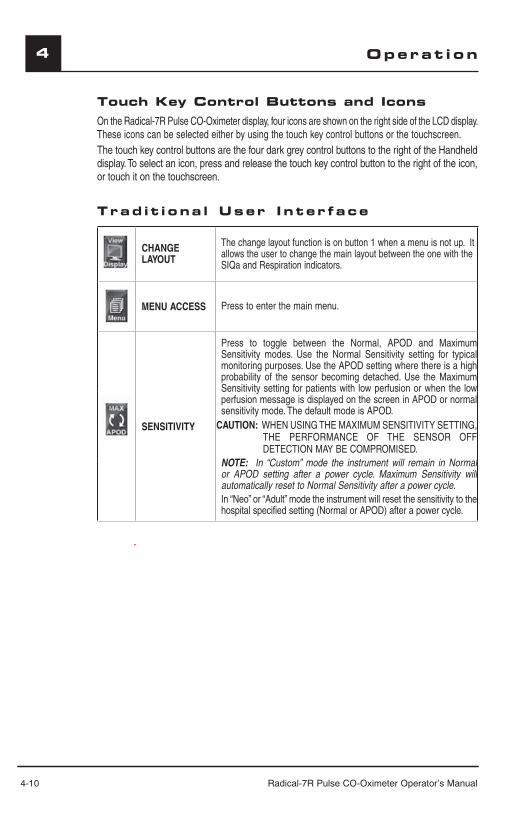
4-10 Radical-7R Pulse CO-Oximeter Operator’s Manual
4
Touch Key Control Buttons and IconsOn the Radical-7R Pulse CO-Oximeter display, four icons are shown on the right side of the LCD display. These icons can be selected either by using the touch key control buttons or the touchscreen. The touch key control buttons are the four dark grey control buttons to the right of the Handheld display. To select an icon, press and release the touch key control button to the right of the icon, or touch it on the touchscreen.
Trad i t i ona l User I n ter face
CHANGE LAYOUT
The change layout function is on button 1 when a menu is not up. It allows the user to change the main layout between the one with the SIQa and Respiration indicators.
MENU ACCESS Press to enter the main menu.
SENSITIVITY
Press to toggle between the Normal, APOD and Maximum Sensitivity modes. Use the Normal Sensitivity setting for typical monitoring purposes. Use the APOD setting where there is a high probability of the sensor becoming detached. Use the Maximum Sensitivity setting for patients with low perfusion or when the low perfusion message is displayed on the screen in APOD or normal sensitivity mode. The default mode is APOD.
CAUTION: WHEN USING THE MAXIMUM SENSITIVITY SETTING, THE PERFORMANCE OF THE SENSOR OFF DETECTION MAY BE COMPROMISED.
NOTE: In “Custom” mode the instrument will remain in Normal or APOD setting after a power cycle. Maximum Sensitivity will automatically reset to Normal Sensitivity after a power cycle. In “Neo” or “Adult” mode the instrument will reset the sensitivity to the hospital specified setting (Normal or APOD) after a power cycle.
Operat ion
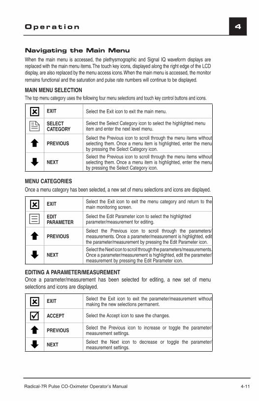
Radical-7R Pulse CO-Oximeter Operator’s Manual 4-11
4Operat ion
Navigating the Main MenuWhen the main menu is accessed, the plethysmographic and Signal IQ waveform displays are replaced with the main menu items. The touch key icons, displayed along the right edge of the LCD display, are also replaced by the menu access icons. When the main menu is accessed, the monitor remains functional and the saturation and pulse rate numbers will continue to be displayed.
MAIN MENU SELECTIONThe top menu category uses the following four menu selections and touch key control buttons and icons.
EXIT Select the Exit icon to exit the main menu.
SELECT CATEGORY
Select the Select Category icon to select the highlighted menu item and enter the next level menu.
PREVIOUSSelect the Previous icon to scroll through the menu items without selecting them. Once a menu item is highlighted, enter the menu by pressing the Select Category icon.
NEXT Select the Previous icon to scroll through the menu items without selecting them. Once a menu item is highlighted, enter the menu by pressing the Select Category icon.
MENU CATEGORIESOnce a menu category has been selected, a new set of menu selections and icons are displayed.
EXIT Select the Exit icon to exit the menu category and return to the main monitoring screen.
EDIT PARAMETER
Select the Edit Parameter icon to select the highlighted parameter/measurement for editing.
PREVIOUSSelect the Previous icon to scroll through the parameters/measurements. Once a parameter/measurement is highlighted, edit the parameter/measurement by pressing the Edit Parameter icon.
NEXT Select the Next icon to scroll through the parameters/measurements. Once a parameter/measurement is highlighted, edit the parameter/measurement by pressing the Edit Parameter icon.
EDITING A PARAMETER/MEASUREMENTOnce a parameter/measurement has been selected for editing, a new set of menu selections and icons are displayed.
EXIT Select the Exit icon to exit the parameter/measurement without making the new selections permanent.
ACCEPT Select the Accept icon to save the changes.
PREVIOUS Select the Previous icon to increase or toggle the parameter/measurement settings.
NEXT Select the Next icon to decrease or toggle the parameter/measurement settings.
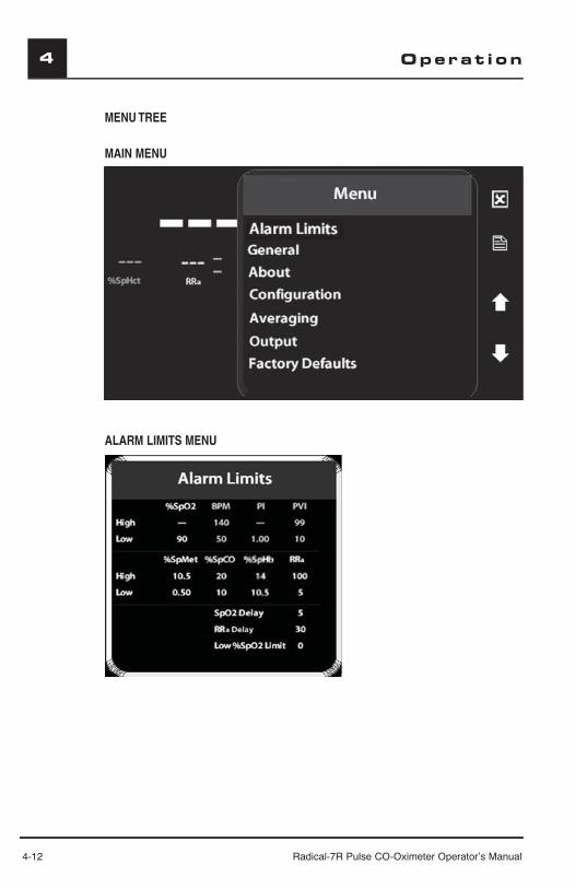
4-12 Radical-7R Pulse CO-Oximeter Operator’s Manual
4 Operat ion
MENU TREE
MAIN MENU
ALARM LIMITS MENU

Radical-7R Pulse CO-Oximeter Operator’s Manual 4-13
4Operat ion
ABOUT MENU
GENERAL MENU
CONFIGURATION MENU
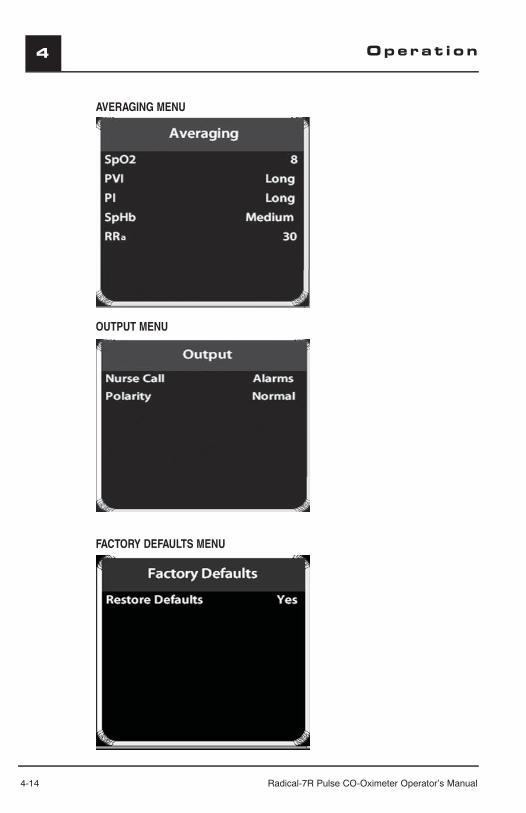
4-14 Radical-7R Pulse CO-Oximeter Operator’s Manual
4
AVERAGING MENU
OUTPUT MENU
FACTORY DEFAULTS MENU
Operat ion
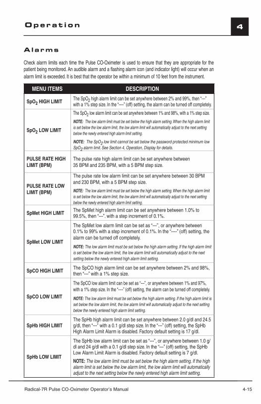
Radical-7R Pulse CO-Oximeter Operator’s Manual 4-15
4Operat ion
A larms
Check alarm limits each time the Pulse CO-Oximeter is used to ensure that they are appropriate for the patient being monitored. An audible alarm and a flashing alarm icon (and indicator light) will occur when an alarm limit is exceeded. It is best that the operator be within a minimum of 10 feet from the instrument.
MENU ITEMS DESCRIPTION
SpO2 HIGH LIMIT The SpO2 high alarm limit can be set anywhere between 2% and 99%, then “---” with a 1% step size. In the “----” (off) setting, the alarm can be turned off completely.
SpO2 LOW LIMIT
The SpO2 low alarm limit can be set anywhere between 1% and 98%, with a 1% step size.
NOTE: The low alarm limit must be set below the high alarm setting. When the high alarm limit is set below the low alarm limit, the low alarm limit will automatically adjust to the next setting below the newly entered high alarm limit setting.
NOTE: The SpO2 low limit cannot be set below the password protected minimum low SpO2 alarm limit. See Section 4, Operation, Display for details.
PULSE RATE HIGH LIMIT (BPM)
The pulse rate high alarm limit can be set anywhere between 35 BPM and 235 BPM, with a 5 BPM step size.
PULSE RATE LOW LIMIT (BPM)
The pulse rate low alarm limit can be set anywhere between 30 BPM and 230 BPM, with a 5 BPM step size.
NOTE: The low alarm limit must be set below the high alarm setting. When the high alarm limit is set below the low alarm limit, the low alarm limit will automatically adjust to the next setting below the newly entered high alarm limit setting.
SpMet HIGH LIMIT The SpMet high alarm limit can be set anywhere between 1.0% to 99.5%, then “---”. with a step increment of 0.1%.
SpMet LOW LIMIT
The SpMet low alarm limit can be set as “---”, or anywhere between 0.1% to 99% with a step increment of 0.1%. In the “----” (off) setting, the alarm can be turned off completely.
NOTE: The low alarm limit must be set below the high alarm setting. If the high alarm limit is set below the low alarm limit, the low alarm limit will automatically adjust to the next setting below the newly entered high alarm limit setting.
SpCO HIGH LIMIT The SpCO high alarm limit can be set anywhere between 2% and 98%, then “---” with a 1% step size.
SpCO LOW LIMIT
The SpCO low alarm limit can be set as “---”, or anywhere between 1% and 97%, with a 1% step size. In the “----” (off) setting, the alarm can be turned off completely.
NOTE: The low alarm limit must be set below the high alarm setting. If the high alarm limit is set below the low alarm limit, the low alarm limit will automatically adjust to the next setting below the newly entered high alarm limit setting.
SpHb HIGH LIMITThe SpHb high alarm limit can be set anywhere between 2.0 g/dl and 24.5 g/dl, then “---” with a 0.1 g/dl step size. In the “---” (off) setting, the SpHb High Alarm Limit Alarm is disabled. Factory default setting is 17 g/dl.
SpHb LOW LIMIT
The SpHb low alarm limit can be set as “---”, or anywhere between 1.0 g/dl and 24 g/dl with a 0.1 g/dl step size. In the “---” (off) setting, the SpHb Low Alarm Limit Alarm is disabled. Factory default setting is 7 g/dl.
NOTE: The low alarm limit must be set below the high alarm setting. If the high alarm limit is set below the low alarm limit, the low alarm limit will automatically adjust to the next setting below the newly entered high alarm limit setting.
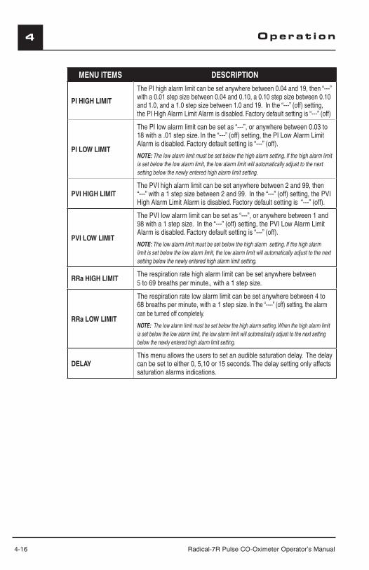
4-16 Radical-7R Pulse CO-Oximeter Operator’s Manual
4 Operat ion
MENU ITEMS DESCRIPTION
PI HIGH LIMIT
The PI high alarm limit can be set anywhere between 0.04 and 19, then “---” with a 0.01 step size between 0.04 and 0.10, a 0.10 step size between 0.10 and 1.0, and a 1.0 step size between 1.0 and 19. In the “---” (off) setting, the PI High Alarm Limit Alarm is disabled. Factory default setting is “---” (off)
PI LOW LIMIT
The PI low alarm limit can be set as “---”, or anywhere between 0.03 to 18 with a .01 step size. In the “---” (off) setting, the PI Low Alarm Limit Alarm is disabled. Factory default setting is “---” (off).
NOTE: The low alarm limit must be set below the high alarm setting. If the high alarm limit is set below the low alarm limit, the low alarm limit will automatically adjust to the next setting below the newly entered high alarm limit setting.
PVI HIGH LIMITThe PVI high alarm limit can be set anywhere between 2 and 99, then “---” with a 1 step size between 2 and 99. In the “---” (off) setting, the PVI High Alarm Limit Alarm is disabled. Factory default setting is “---” (off).
PVI LOW LIMIT
The PVI low alarm limit can be set as “---”, or anywhere between 1 and 98 with a 1 step size. In the “---” (off) setting, the PVI Low Alarm Limit Alarm is disabled. Factory default setting is “---” (off).
NOTE: The low alarm limit must be set below the high alarm setting. If the high alarm limit is set below the low alarm limit, the low alarm limit will automatically adjust to the next setting below the newly entered high alarm limit setting.
RRa HIGH LIMITThe respiration rate high alarm limit can be set anywhere between 5 to 69 breaths per minute., with a 1 step size.
RRa LOW LIMIT
The respiration rate low alarm limit can be set anywhere between 4 to 68 breaths per minute, with a 1 step size. In the “----” (off) setting, the alarm can be turned off completely.
NOTE: The low alarm limit must be set below the high alarm setting. When the high alarm limit is set below the low alarm limit, the low alarm limit will automatically adjust to the next setting below the newly entered high alarm limit setting.
DELAYThis menu allows the users to set an audible saturation delay. The delay can be set to either 0, 5,10 or 15 seconds. The delay setting only affects saturation alarms indications.

Radical-7R Pulse CO-Oximeter Operator’s Manual 4-17
4
Genera l
MENU ITEMS DESCRIPTION
FASTSAT Select Yes to activate the FastSat algorithm. In the 2 and 4 seconds averaging mode, the FastSat algorithm is automatically enabled.
SMART TONESelect Yes to activate the SmartTone function. This will allow the audible pulse to continue to beep when the pleth graph shows signs of motion. Select NO to turn off SmartTone.
PULSE TONE Select YES to activate the Pulse Tone function. This will allow the audible pulse to continue to beep upon each patient pulsation..
AboutThis displays the copyright and software versions of the Handheld and Docking Station.
MENU ITEMS
Copyright Date
Masimo Corporation
Masimo SET Software Version
Handheld Software Version
D-Station Software Version
Conf i gurat ion
MENU ITEMS DESCRIPTION
Line Frequency
Set to 50 or 60Hz.
Set to match regional power line frequency to allow for cancellation of noise introduced by fl uorescent lights and other sources. Factory default is 60 Hz.
Rapid Desat Limit
Set to Off, -5 or -10.When set to -5%, this feature overrides the Alarm Delay (audible alarms silenced) and the instrument will alarm if SpO2 rapidly falls to 5% or 10% below the alarm limit. Factory default is -5%.
SpHb Cal
Set to Arterial or Venous.
This feature provides an SpHb (Arterial) or SpHbV (Venous) value that displays on the main screen.
NOTE: The hemorheologic profi le of arterial and venous blood samples can vary1. To accommodate this difference, the Radical-7R provides the option of displaying a SpHb parameter that is based on either Arterial or Venous SpHb laboratory blood sample draw.
Changes to SpHb are included in output data. SpOC calculation will always be based on the arterial SpHb.
Operat ion
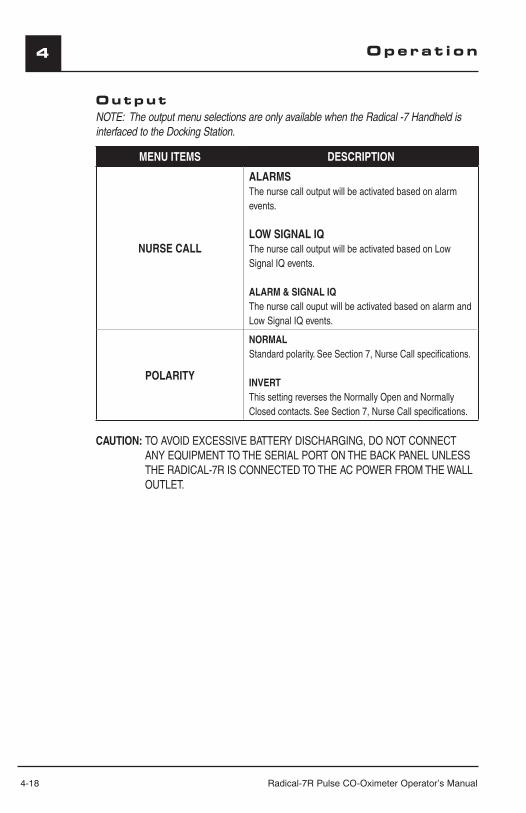
4-18 Radical-7R Pulse CO-Oximeter Operator’s Manual
4 Operat ion
OutputNOTE: The output menu selections are only available when the Radical -7 Handheld is interfaced to the Docking Station.
MENU ITEMS DESCRIPTION
NURSE CALL
ALARMSThe nurse call output will be activated based on alarm events.
LOW SIGNAL IQThe nurse call output will be activated based on Low Signal IQ events.
ALARM & SIGNAL IQThe nurse call ouput will be activated based on alarm and Low Signal IQ events.
POLARITY
NORMALStandard polarity. See Section 7, Nurse Call specifi cations.
INVERTThis setting reverses the Normally Open and Normally Closed contacts. See Section 7, Nurse Call specifi cations.
CAUTION: TO AVOID EXCESSIVE BATTERY DISCHARGING, DO NOT CONNECT ANY EQUIPMENT TO THE SERIAL PORT ON THE BACK PANEL UNLESS THE RADICAL-7R IS CONNECTED TO THE AC POWER FROM THE WALL OUTLET.

Radical-7R Pulse CO-Oximeter Operator’s Manual 4-19
4
SatShare Operat ion
When the SatShare cable is connected to the Radical-7R Pulse CO-Oximeter and to a multiparameter patient monitor, the Radical-7R Pulse CO-Oximeter automatically starts to operate in the SatShare mode.
In the SatShare mode, Radical-7R Pulse CO-Oximeter operates as follows:
■ All visual alarms remain active.
■ All audible alarms may be disabled by software configuration of the Radical-7R Pulse CO-Oximeter. Refer to Section 4, Alarms.
■ The SpO2 and pulse rate numbers may or may not be displayed on the Radical-7R Pulse CO-Oximeter display depending on the SatShare Numbers setting of the General menu. Refer to Section 3, SatShare Setup.
■ All other items are displayed, including the alarm limits, the plethysmogram and Signal IQ waveform.
■ The user can access the menu system.
■ If the SatShare cable is connected to the Radical-7R Pulse CO-Oximeter only, and not to a patient monitor, the SatShare cable type is flashing on the LCD screen.
■ Once the Radical-7R Pulse CO-Oximeter detects the presence of a patient monitor, the SatShare cable type remains constantly displayed on the LCD screen.
■ Patient Alarms of the multiparameter patient monitor will be triggered by the alarm setting of the patient monitor and not the Radical-7 Pulse CO-Oximeter. To synchronize the alarm events set the alarm limits of the Radical-7 Pulse CO-Oximeter to those of the patient monitor, or vice versa.
■ Once the Radical-7R Pulse CO-Oximeter detects that the SatShare cable is disconnected from the patient monitor, or if the patient monitor is turned off, the Radical-7R automatically returns to normal, standalone operation.
■ In the SatShare mode, the pulse beep tone of the Radical-7R Pulse CO-Oximeter is initially set to the lowest volume (mute). The pulse beep volume can be manually increased. Refer to Section 4, Traditional User Interface.
■ The Radical-7R Pulse CO-Oximeter may automatically set the averaging time during SatShare operation. For averaging times of 10 seconds and higher, the Radical-7 Pulse CO-Oximeter will automatically set the averaging time to 8 seconds during SatShare operation. Averaging times of 2, 4 or 8 seconds remain unchanged during SatShare operation. When the Radical-7R Pulse CO-Oximeter returns to non-SatShare operation, the Radical-7 Pulse CO-Oximeter will maintain the averaging time setting used in the SatShare mode.
■ When the Radical-7R Pulse CO-Oximeter starts to operate in the SatShare mode the sensitivity mode is set to Normal sensitivity. The sensitivity mode can manually be set to Maximum or APOD sensitivity. Refer to Section 2, Handheld Front Panel.
Operat ion
4-20 Radical-7R Pulse CO-Oximeter Operator’s Manual
4
SatShare Operat ion ( cont inued )■ While operating in the SatShare mode, the Radical-7R Pulse CO-Oximeter may
automatically disable the SatShare interface if the perfusion index drops below 0.1% while the sensitivity is set to Max sensitivity. To enable the SatShare interface again, set the Radical-7R Pulse CO-Oximeter to the Normal or APOD sensitivity mode, increase the perfusion at the measurement site (by warming the patient or sensor site), or move the sensor to a site with better perfusion.
CAUTIONS:
■ SATSHARE SIGNALS ARE IDEAL SIMULATED WAVEFORMS CORRESPONDING TO THE CALCULATED SATURATION AND PULSE RATE VALUES AND DO NOT CONTAIN ALL OF THE INFORMATION CONTAINED IN PHYSIOLOGICAL WAVEFORMS. THE MULTIPARAMETER PATIENT MONITOR DECODES THESE SIGNALS INTO SATURATION AND PULSE RATE VALUES.
■ DURING SATSHARE OPERATION, THE AUDIBLE ALARMS MAY BE MUTED ON THE RADICAL-7R PULSE CO-OXIMETER. WHEN THE AUDIBLE ALARM IS MUTED (INDICATED BY A BELL WITH A SLASH THROUGH IT) ON THE RADICAL-7 PULSE CO-OXIMETER, USE THE MULTIPARAMETER MONITOR FOR AUDIBLE ALARM INDICATION.
■ THE (RADICAL-7R) SpO2 AND PULSE RATE AUDIBLE ALARMS MAY BE DISABLED WHEN THE RADICAL-7R IS CONFIGURED WITH RAINBOW PARAMETERS/MEASUREMENTS. REFER TO SECTION 4 ALARMS.
■ THE RADICAL-7R REVERTS TO THE INTERFACE ALARM "SpO2/BPM" “Yes” SETTING DURING POWER INTERRUPTIONS OR WHEN THE SATSHARE CONNECTION IS LOST OR THE DEVICE BECOMES SEPARATED FROM THE DOCKING STATION. THIS ENSURES THAT THE RADICAL-7R PROVIDES AUDIBLE ALARMS FOR SpO2 AND PULSE RATE WHEN THE CONNECTION TO THE INTERFACED SYSTEM BECOMES COMPROMISED.
■ DURING SATSHARE OPERATION DO NOT USE THE PLETHYSMOGRAPHIC WAVEFORM DISPLAY ON THE MULTIPARAMETER MONITOR FOR DIAGNOSTIC PURPOSES. INSTEAD, USE THE PLETHYSMOGRAPHIC WAVEFORM DISPLAYED ON THE RADICAL-7R SCREEN.
■ TO AVOID EXCESSIVE BATTERY DISCHARGING, DO NOT CONNECT ANY EQUIPMENT TO THE SATSHARE CONNECTOR UNLESS THE RADICAL-7R IS CONNECTED TO THE AC MAINS POWER SUPPLY.
■ ONLY USE A SATSHARE CABLE THAT HAS A FERRITE BEAD INSTALLED.
■ ONLY SPO2 AND PULSE RATE CAN BE DISPLAYED ON THE MULTIPARAMETER MONITOR WITH SATSHARE.
To return from SatShare operation to normal standalone operation, simply disconnect the SatShare cable from the patient monitor or disconnect the SatShare cable from the SatShare connector on the back of the Radical-7R Pulse CO-Oximeter.
Operat ion
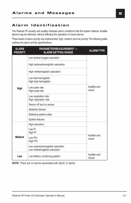
Radical-7R Pulse CO-Oximeter Operator’s Manual 5-1
5
Alarm Ident i f i cat i on
The Radical-7R visually and audibly indicates alarm conditions that the system detects. Audible alarms may be silenced, without affecting the operation of visual alarms.
Three levels of alarm priority are implemented: high, medium and low priority. The following table outlines the alarm priority specifications.
ALARM PRIORITY
PARAMETER/MEASUREMENT —ALARM SETTING RANGE
ALARM TYPE
High
Low arterial oxygen saturation
Audible and visual
High carboxyhemoglobin saturation
High methemoglobin saturation
Low total hemoglobinHigh total hemoglobin
Low pulse rateHigh pulse rate
Low respiration rateHigh respiration rate
Sensor off and no sensor
Defective Sensor
Defective patient cable
System failures
Medium
High saturation
Audible and visual
Low PIHigh PI
Low PVIHigh PVI
Low carboxyhemoglobin saturationLow methemoglobin saturation
Low Low battery, monitoring patientAudible and Visual
NOTE: There are no alarms associated with SpOC or SpHct.
Alarms and Messages
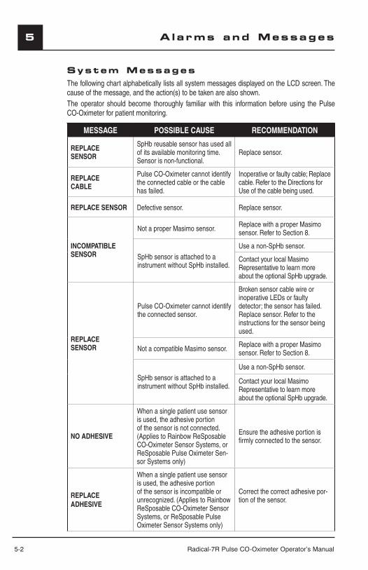
5-2 Radical-7R Pulse CO-Oximeter Operator’s Manual
5 Alarms and Messages
System MessagesThe following chart alphabetically lists all system messages displayed on the LCD screen. The cause of the message, and the action(s) to be taken are also shown.The operator should become thoroughly familiar with this information before using the Pulse CO-Oximeter for patient monitoring.
MESSAGE POSSIBLE CAUSE RECOMMENDATION
REPLACE SENSOR
SpHb reusable sensor has used all of its available monitoring time.Sensor is non-functional.
Replace sensor.
REPLACECABLE
Pulse CO-Oximeter cannot identify the connected cable or the cable has failed.
Inoperative or faulty cable; Replace cable. Refer to the Directions for Use of the cable being used.
REPLACE SENSOR Defective sensor. Replace sensor.
INCOMPATIBLE SENSOR
Not a proper Masimo sensor. Replace with a proper Masimo sensor. Refer to Section 8.
SpHb sensor is attached to a instrument without SpHb installed.
Use a non-SpHb sensor.
Contact your local Masimo Representative to learn more about the optional SpHb upgrade.
REPLACESENSOR
Pulse CO-Oximeter cannot identify the connected sensor.
Broken sensor cable wire or inoperative LEDs or faulty detector; the sensor has failed. Replace sensor. Refer to the instructions for the sensor being used.
Not a compatible Masimo sensor. Replace with a proper Masimo sensor. Refer to Section 8.
SpHb sensor is attached to a instrument without SpHb installed.
Use a non-SpHb sensor.
Contact your local Masimo Representative to learn more about the optional SpHb upgrade.
NO ADHESIVE
When a single patient use sensor is used, the adhesive portion of the sensor is not connected. (Applies to Rainbow ReSposable CO-Oximeter Sensor Systems, or ReSposable Pulse Oximeter Sen-sor Systems only)
Ensure the adhesive portion is fi rmly connected to the sensor.
REPLACEADHESIVE
When a single patient use sensor is used, the adhesive portion of the sensor is incompatible or unrecognized. (Applies to Rainbow ReSposable CO-Oximeter Sensor Systems, or ReSposable Pulse Oximeter Sensor Systems only)
Correct the correct adhesive por-tion of the sensor.
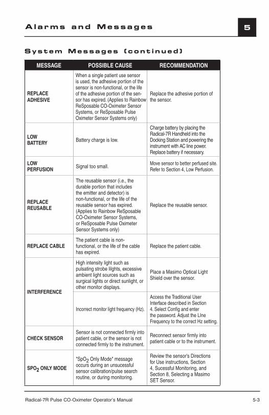
Radical-7R Pulse CO-Oximeter Operator’s Manual 5-3
5
MESSAGE POSSIBLE CAUSE RECOMMENDATION
REPLACE ADHESIVE
When a single patient use sensor is used, the adhesive portion of the sensor is non-functional, or the life of the adhesive portion of the sen-sor has expired. (Applies to Rainbow ReSposable CO-Oximeter Sensor Systems, or ReSposable Pulse Oximeter Sensor Systems only)
Replace the adhesive portion of the sensor.
LOW BATTERY Battery charge is low.
Charge battery by placing the Radical-7R Handheld into the Docking Station and powering the instrument with AC line power. Replace battery if necessary.
LOW PERFUSION Signal too small. Move sensor to better perfused site.
Refer to Section 4, Low Perfusion.
REPLACE REUSABLE
The reusable sensor (i.e., the durable portion that includes the emitter and detector) is non-functional, or the life of the reusable sensor has expired. (Applies to Rainbow ReSposable CO-Oximeter Sensor Systems, or ReSposable Pulse Oximeter Sensor Systems only)
Replace the reusable sensor.
REPLACE CABLEThe patient cable is non-functional, or the life of the cable has expired.
Replace the patient cable.
INTERFERENCE
High intensity light such as pulsating strobe lilghts, excessive ambient light sources such as surgical lights or direct sunlight, or other monitor displays.
Place a Masimo Optical Light Shield over the sensor.
Incorrect monitor light frequency (Hz).
Access the Traditional User Interface described in Section 4. Select Confi g and enter the password. Adjust the LIne Frequency to the correct Hz setting.
CHECK SENSORSensor is not connected fi rmly into patient cable, or the sensor is not connected fi rmly to the instrument.
Reconnect sensor fi rmly into patient cable or to the instrument.
SPO2 ONLY MODE
"SpO2 Only Mode" message occurs during an unsucessful sensor calibration/pulse search routine, or during monitoring.
Review the sensor's Directions for Use instructions, Section 4, Sucessful Monitoring, and Section 8, Selecting a Masimo SET Sensor.
Alarms and Messages
System Messages ( cont inued )
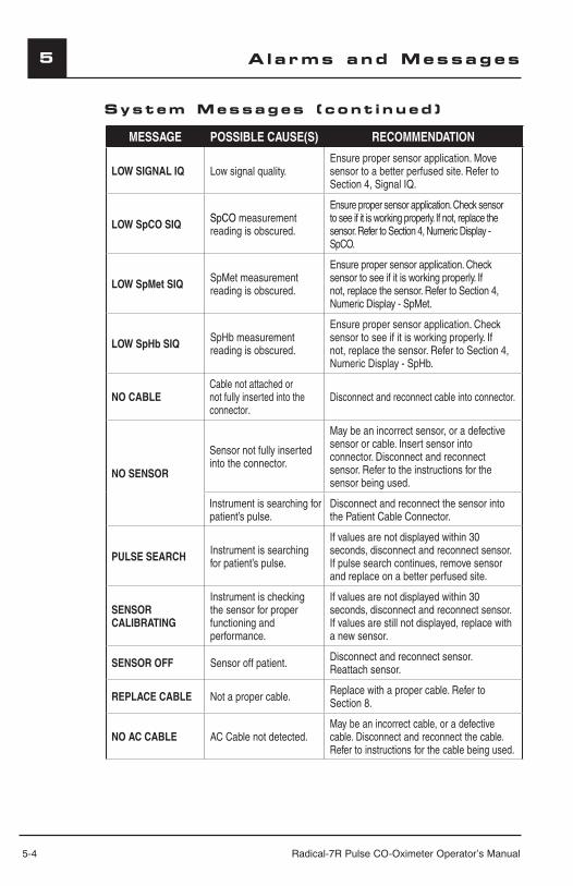
5-4 Radical-7R Pulse CO-Oximeter Operator’s Manual
5 Alarms and Messages
System Messages ( cont inued )
MESSAGE POSSIBLE CAUSE(S) RECOMMENDATION
LOW SIGNAL IQ Low signal quality.Ensure proper sensor application. Move sensor to a better perfused site. Refer to Section 4, Signal IQ.
LOW SpCO SIQ SpCO measurement reading is obscured.
Ensure proper sensor application. Check sensor to see if it is working properly. If not, replace the sensor. Refer to Section 4, Numeric Display - SpCO.
LOW SpMet SIQ SpMet measurement reading is obscured.
Ensure proper sensor application. Check sensor to see if it is working properly. If not, replace the sensor. Refer to Section 4, Numeric Display - SpMet.
LOW SpHb SIQ SpHb measurement reading is obscured.
Ensure proper sensor application. Check sensor to see if it is working properly. If not, replace the sensor. Refer to Section 4, Numeric Display - SpHb.
NO CABLECable not attached or not fully inserted into the connector.
Disconnect and reconnect cable into connector.
NO SENSOR
Sensor not fully inserted into the connector.
May be an incorrect sensor, or a defective sensor or cable. Insert sensor into connector. Disconnect and reconnect sensor. Refer to the instructions for the sensor being used.
Instrument is searching for patient’s pulse.
Disconnect and reconnect the sensor into the Patient Cable Connector.
PULSE SEARCH Instrument is searching for patient’s pulse.
If values are not displayed within 30 seconds, disconnect and reconnect sensor. If pulse search continues, remove sensor and replace on a better perfused site.
SENSOR CALIBRATING
Instrument is checking the sensor for proper functioning and performance.
If values are not displayed within 30 seconds, disconnect and reconnect sensor. If values are still not displayed, replace with a new sensor.
SENSOR OFF Sensor off patient. Disconnect and reconnect sensor. Reattach sensor.
REPLACE CABLE Not a proper cable. Replace with a proper cable. Refer to Section 8.
NO AC CABLE AC Cable not detected.May be an incorrect cable, or a defective cable. Disconnect and reconnect the cable. Refer to instructions for the cable being used.
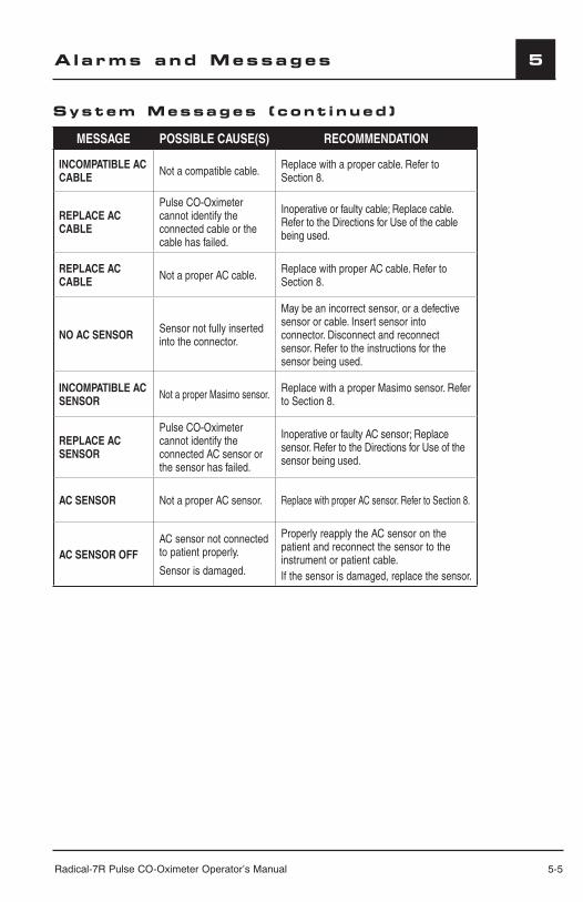
Radical-7R Pulse CO-Oximeter Operator’s Manual 5-5
5
5-5
Alarms and Messages
MESSAGE POSSIBLE CAUSE(S) RECOMMENDATION
INCOMPATIBLE AC CABLE Not a compatible cable. Replace with a proper cable. Refer to
Section 8.
REPLACE AC CABLE
Pulse CO-Oximeter cannot identify the connected cable or the cable has failed.
Inoperative or faulty cable; Replace cable. Refer to the Directions for Use of the cable being used.
REPLACE AC CABLE Not a proper AC cable. Replace with proper AC cable. Refer to
Section 8.
NO AC SENSOR Sensor not fully inserted into the connector.
May be an incorrect sensor, or a defective sensor or cable. Insert sensor into connector. Disconnect and reconnect sensor. Refer to the instructions for the sensor being used.
INCOMPATIBLE AC SENSOR Not a proper Masimo sensor. Replace with a proper Masimo sensor. Refer
to Section 8.
REPLACE AC SENSOR
Pulse CO-Oximeter cannot identify the connected AC sensor or the sensor has failed.
Inoperative or faulty AC sensor; Replace sensor. Refer to the Directions for Use of the sensor being used.
AC SENSOR Not a proper AC sensor. Replace with proper AC sensor. Refer to Section 8.
AC SENSOR OFFAC sensor not connected to patient properly.
Sensor is damaged.
Properly reapply the AC sensor on the patient and reconnect the sensor to the instrument or patient cable.If the sensor is damaged, replace the sensor.
System Messages ( cont inued )

Radical-7R Pulse CO-Oximeter Operator’s Manual 6-1
6Troub l eshoot ing
Troub l eshoot ingThe following chart describes what to do if the Radical-7R Pulse CO-Oximeter system does not operate properly or fails.
PROBLEMPOSSIBLE CAUSE(S)
RECOMMENDATION
INSTRUMENT DOES NOT POWER ON
One or both of the fuses are not operating properly. Replace the fuses.
INSTRUMENT POWERS ON BUT THE GRAPHIC DISPLAY IS BLANK
The viewing contrast is not correct. Instrument requires service.
CONTINUOUS SPEAKER TONE Internal failure.
Instrument requires service. Press the Alarm Silence button to silence the alarm. If alarm continues to sound, power down instrument and remove Handheld battery if necessary.
BUTTONS DON’T WORK WHEN PRESSED Internal failure. Instrument requires service.
DEFECTIVE SENSOR MESSAGE Sensor or cable is broken.
Visually check the sensor LED if it is flashing on and off.
If not, reconnect the cable and check the LED again.
If the LED still fails to come on, replace the sensor and/or cable.
SpO2 NUMBER FLASHES Saturation alarm limit exceeded.
Assess/address patient condition.Re-set alarm limits if indicated.
SENSOR OFF MESSAGESensor not connected to patient properly.
Sensor is damaged.
Properly reapply the sensor on the patient and reconnect the sensor to the instrument or patient cable.If the sensor is damaged, replace the sensor.
NO SENSOR MESSAGE
Sensor is disconnected from patient cable.Sensor connected upside down into patient cable.
Check to see if the sensor LED is flashing. Disconnect and reconnect the sensor. If the LED fails to operate, replace the sensor.
LOW PERFUSION
Improper sensor type.Poorly perfused site.Sensor is too tight.A disorder such as hypothermia, vasoconstriction, hypovolemia, peripheral vascular disease or anemia.Sensor is damaged.
Verify proper sensor and sensor size for the patient.Check and see if blood flow to the site is restricted. Be sure that the sensor is not on too tight.Set instrument to MAX sensitivity.Warm the patient or sensor site.Move sensor to better perfused site.
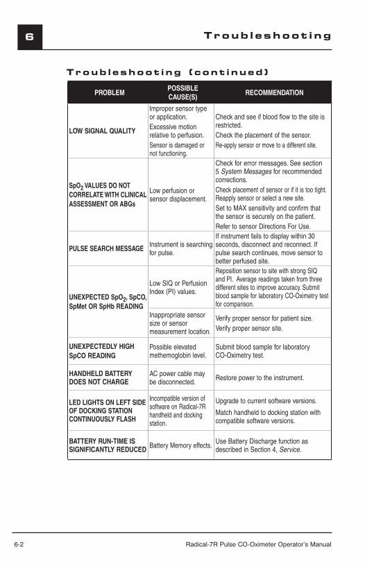
6-2 Radical-7R Pulse CO-Oximeter Operator’s Manual
6
PROBLEMPOSSIBLE CAUSE(S)
RECOMMENDATION
LOW SIGNAL QUALITY
Improper sensor type or application.Excessive motion relative to perfusion.Sensor is damaged or not functioning.
Check and see if blood flow to the site is restricted.Check the placement of the sensor.Re-apply sensor or move to a different site.
SpO2 VALUES DO NOT CORRELATE WITH CLINICAL ASSESSMENT OR ABGs
Low perfusion or sensor displacement.
Check for error messages. See section 5 System Messages for recommended corrections.Check placement of sensor or if it is too tight. Reapply sensor or select a new site.Set to MAX sensitivity and confirm that the sensor is securely on the patient.Refer to sensor Directions For Use.
PULSE SEARCH MESSAGE Instrument is searching for pulse.
If instrument fails to display within 30 seconds, disconnect and reconnect. If pulse search continues, move sensor to better perfused site.
UNEXPECTED SpO2, SpCO, SpMet OR SpHb READING
Low SIQ or Perfusion Index (PI) values.
Reposition sensor to site with strong SIQ and PI. Average readings taken from three different sites to improve accuracy. Submit blood sample for laboratory CO-Oximetry test for comparison.
Inappropriate sensor size or sensor measurement location.
Verify proper sensor for patient size.Verify proper sensor site.
UNEXPECTEDLY HIGH SpCO READING
Possible elevated methemoglobin level.
Submit blood sample for laboratory CO-Oximetry test.
HANDHELD BATTERY DOES NOT CHARGE
AC power cable may be disconnected. Restore power to the instrument.
LED LIGHTS ON LEFT SIDE OF DOCKING STATION CONTINUOUSLY FLASH
Incompatible version of software on Radical-7R handheld and docking station.
Upgrade to current software versions.
Match handheld to docking station with compatible software versions.
BATTERY RUN-TIME IS SIGNIFICANTLY REDUCED Battery Memory effects. Use Battery Discharge function as
described in Section 4, Service.
Troub l eshoot ing
Troub l eshoot ing ( cont inued )
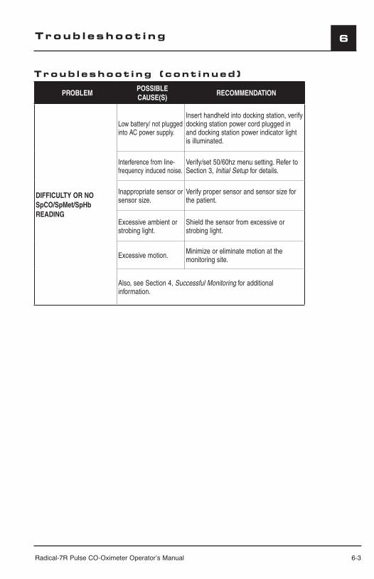
Radical-7R Pulse CO-Oximeter Operator’s Manual 6-3
6
PROBLEMPOSSIBLE CAUSE(S)
RECOMMENDATION
DIFFICULTY OR NO SpCO/SpMet/SpHb READING
Low battery/ not plugged into AC power supply.
Insert handheld into docking station, verify docking station power cord plugged in and docking station power indicator light is illuminated.
Interference from line-frequency induced noise.
Verify/set 50/60hz menu setting. Refer to Section 3, Initial Setup for details.
Inappropriate sensor or sensor size.
Verify proper sensor and sensor size for the patient.
Excessive ambient or strobing light.
Shield the sensor from excessive or strobing light.
Excessive motion. Minimize or eliminate motion at the monitoring site.
Also, see Section 4, Successful Monitoring for additional information.
Troub l eshoot ing ( cont inued )
Troub l eshoot ing
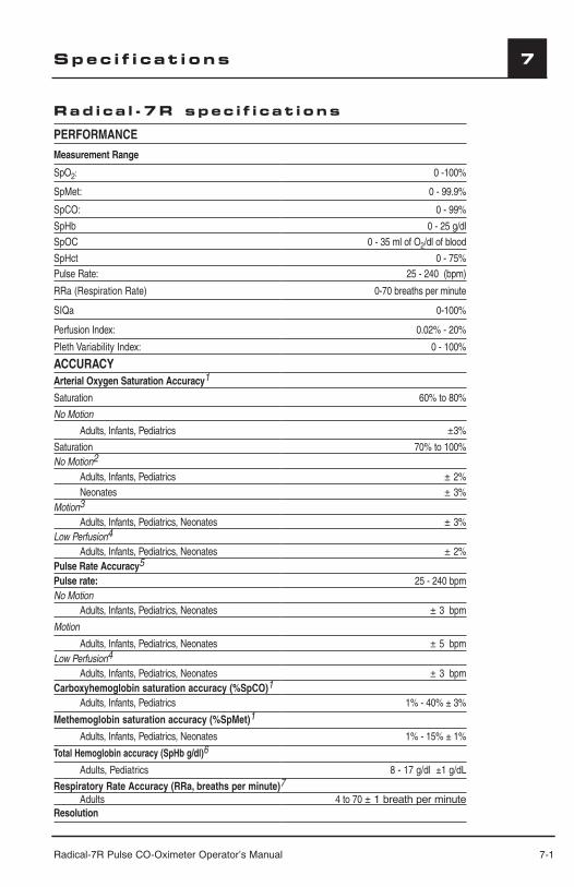
Radical-7R Pulse CO-Oximeter Operator’s Manual 7-1
7Spec i f i cat i ons
Rad ica l -7R spec i f i cat i ons
PERFORMANCE
Measurement Range
SpO2: 0 -100%
SpMet: 0 - 99.9%
SpCO: 0 - 99%
SpHb 0 - 25 g/dl
SpOC 0 - 35 ml of O2/dl of blood
SpHct 0 - 75%Pulse Rate: 25 - 240 (bpm)
RRa (Respiration Rate) 0-70 breaths per minute
SIQa 0-100%
Perfusion Index: 0.02% - 20%
Pleth Variability Index: 0 - 100%
ACCURACYArterial Oxygen Saturation Accuracy1
Saturation 60% to 80%
No Motion
Adults, Infants, Pediatrics ±3%
Saturation 70% to 100%No Motion2
Adults, Infants, Pediatrics ± 2%Neonates ± 3%
Motion3
Adults, Infants, Pediatrics, Neonates ± 3%Low Perfusion4
Adults, Infants, Pediatrics, Neonates ± 2%Pulse Rate Accuracy5
Pulse rate: 25 - 240 bpmNo Motion
Adults, Infants, Pediatrics, Neonates ± 3 bpm
Motion
Adults, Infants, Pediatrics, Neonates ± 5 bpmLow Perfusion4
Adults, Infants, Pediatrics, Neonates ± 3 bpmCarboxyhemoglobin saturation accuracy (%SpCO)1
Adults, Infants, Pediatrics 1% - 40% ± 3%
Methemoglobin saturation accuracy (%SpMet)1
Adults, Infants, Pediatrics, Neonates 1% - 15% ± 1%
Total Hemoglobin accuracy (SpHb g/dl)6
Adults, Pediatrics 8 - 17 g/dl ±1 g/dL
Respiratory Rate Accuracy (RRa, breaths per minute)7
Adults 4 to 70 ± 1 breath per minuteResolution
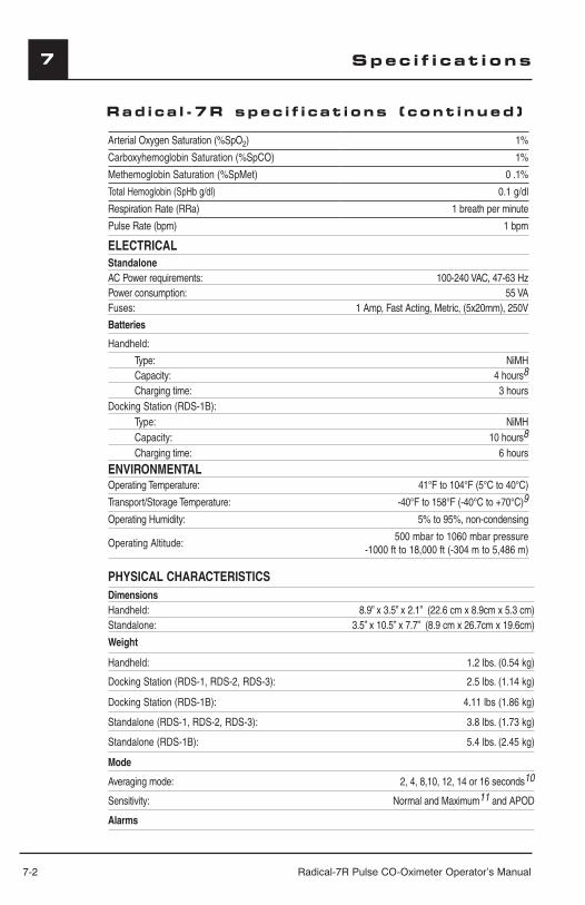
7-2 Radical-7R Pulse CO-Oximeter Operator’s Manual
7
Arterial Oxygen Saturation (%SpO2) 1%
Carboxyhemoglobin Saturation (%SpCO) 1%
Methemoglobin Saturation (%SpMet) 0 .1%
Total Hemoglobin (SpHb g/dl) 0.1 g/dl
Respiration Rate (RRa) 1 breath per minute
Pulse Rate (bpm) 1 bpm
ELECTRICALStandaloneAC Power requirements: 100-240 VAC, 47-63 HzPower consumption: 55 VAFuses: 1 Amp, Fast Acting, Metric, (5x20mm), 250V
Batteries
Handheld:
Type: NiMHCapacity: 4 hours8
Charging time: 3 hoursDocking Station (RDS-1B):
Type: NiMHCapacity: 10 hours8
Charging time: 6 hours
ENVIRONMENTALOperating Temperature: 41°F to 104°F (5°C to 40°C)
Transport/Storage Temperature: -40°F to 158°F (-40°C to +70°C)9
Operating Humidity: 5% to 95%, non-condensing
Operating Altitude:500 mbar to 1060 mbar pressure
-1000 ft to 18,000 ft (-304 m to 5,486 m)
PHYSICAL CHARACTERISTICSDimensionsHandheld: 8.9” x 3.5” x 2.1” (22.6 cm x 8.9cm x 5.3 cm)Standalone: 3.5” x 10.5” x 7.7” (8.9 cm x 26.7cm x 19.6cm)
Weight
Handheld: 1.2 lbs. (0.54 kg)
Docking Station (RDS-1, RDS-2, RDS-3): 2.5 lbs. (1.14 kg)
Docking Station (RDS-1B): 4.11 lbs (1.86 kg)
Standalone (RDS-1, RDS-2, RDS-3): 3.8 lbs. (1.73 kg)
Standalone (RDS-1B): 5.4 lbs. (2.45 kg)
Mode
Averaging mode: 2, 4, 8,10, 12, 14 or 16 seconds10
Sensitivity: Normal and Maximum11 and APOD
Alarms
Spec i f i cat i ons
Rad ica l -7R spec i f i cat i ons ( cont inued )
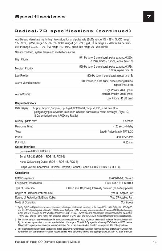
Radical-7R Pulse CO-Oximeter Operator’s Manual 7-3
7Spec i f i cat i ons
Audible and visual alarms for high low saturation and pulse rate (SpO2 range 1% - 99%, SpCO range 1% - 98%, SpMet range 1% - 99.5%, SpHb range1 g/dl - 24.5 g/dl, RRa range 4 - 70 breaths per min-ute, PI range 0.03% - 19%, PVI range 1% - 99%, pulse rate range 30 - 235 BPM)
Sensor condition, system failure and low battery alarms
High Priority:571 Hz tone, 5 pulse burst, pulse spacing: 0.250s,
0.250s, 0.500s, 0.250s, repeat time:10s
Medium Priority:550 Hz tone, 3 pulse burst, pulse spacing: 0.375s,
0.375s, repeat time: 7s
Low Priority: 500 Hz tone, 1 pulse burst, repeat time: 5s
Alarm Muted reminder:500Hz tone, 2 pulse burst, pulse spacing 0.375s,
repeat time: 3min.
Alarm Volume:High Priority: 70 dB (min),
Medium Priority: 70 dB (min),
Low Priority: 45 dB (min)
Display/Indicators
Data display: %SpO2, %SpCO, %SpMet, SpHb g/dl, SpOC ml/dl, %SpHct, PVI, pulse rate, RRa, plethysmographic waveform, respiration indicator, alarm status, status messages, Signal IQ, SIQa, perfusion index, APOD and FastSat
Display update rate: 1 second
Response Time: < 20 second delay
Type: Backlit Active Matrix TFT LCD
Pixels: 480 x 272 dots
Dot Pitch: 0.25 mmOutput Interface
Satshare (RDS-1, RDS-1B)
Serial RS-232 (RDS-1, RDS 1B, RDS-3)
Nurse Call/Analog Output (RDS-1, RDS-1B, RDS-3)
Philips Vuelink, Spacelabs Universal Flexport, RadNet, RadLink (RDS-1, RDS-1B, RDS-3)
Compliance
EMC Compliance: EN60601-1-2, Class B
Equipment Classification: IEC 60601-1 / UL 60601-1
Type of Protection Class 1 (on AC power), Internally powered (on battery power)
Degree of Protection-Patient Cable: Type BF-Applied Part
Degree of Protection-SatShare Cable: Type CF-Applied Part
Mode of Operation: Continuous
1 SpO2, SpCO and SpMet accuracy was determined by testing on healthy adult volunteers in the range 60% - 100% SpO2, 0% - 40% SpCO and 0% - 15% SpMet against a laboratory CO-Oximeter. SpO2 and SpMet accuracy was determined on 16 neonatal NICU patients ranging in age from 7 to 135 days old and weighting between 0.5 and 4.25 kgs. Seventy-nine (79) data samples were collected over a range of 70 - 100% SaO2 and 0.5 - 2.5% HbMet with a resultant accuracy of 2.9% SpO2 and 0.9% SpMet. Contact Masimo for testing specifications.
2 The Masimo sensors have been validated for no motion accuracy in human blood studies on healthy adult male and female volunteers with light to dark skin pigmentation in induced hypoxia studies in the range of 70-100% SpO2 against a laboratory CO-Oximeter and ECG monitor. This variation equals plus or minus one standard deviation. Plus or minus one standard deviation encompasses 68% of the population.
3 The Masimo sensors have been validated for motion accuracy in human blood studies on healthy adult male and female volunteers with light to dark skin pigmentation in induced hypoxia studies while performing rubbing and tapping motions, at 2 to 4 Hz at an amplitude
Rad ica l -7R spec i f i cat i ons ( cont inued )

7-4 Radical-7R Pulse CO-Oximeter Operator’s Manual
7
of 1 to 2 cm and a non-repetitive motion between 1 to 5 Hz at an amplitude of 2 to 3 cm in induced hypoxia studies in the range of 70-100% SpO2 against a laboratory CO-Oximeter and ECG monitor. This variation equals plus or minus one standard deviation. Plus or minus one standard deviation encompasses 68% of the population.
4 The Radical-7R has been validated for low perfusion accuracy in bench-top testing against a Fluke Biotek Index 2 simulator and Masimo's simulator with signal strengths of greater than 0.02% and transmission of greater than 5% for saturations and pulse rates within the stated accuracy specifications. This variation equals plus or minus one standard deviation. Plus or minus one standard deviation encompasses 68% of the population.
5 Masimo sensors have been validated for pulse rate accuracy for the range of 25-240 bpm in bench top testing against a Biotek Index 2 simulator. This variation equals plus or minus one standard deviation which encompasses 68% of the population.
6 SpHb accuracy has been validated on healthy adult male and female volunteers and on surgical patients with light to dark skin pigmentation in the range of 8 g/dL to 17 g/dL SpHb against a laboratory CO-Oximeter. The variation equals plus or minus one standard deviation which encompasses 68% of the population. The SpHb accuracy has not been validated with motion or low perfusion.
7 Respiration rate accuracy for the Masimo Acoustic Respiration sensor and instrument has been validated for the range of 4 to 70 breaths per minute in bench top testing. Clinical validation for up to 30 breaths per minute was also performed with the Masimo Acoustic Respiration sensor and instrument.
8 This represents approximate run time at the lowest indicator brightness and pulse tone turned off using a fully charged battery.
9 If the batteries are to be stored for extended periods of time, it is recommended that they be stored between -20°C to +30°C, and at a relative humidity less than 85%. If stored for a prolonged period at environmental conditions beyond these limits, overall battery capacity may be diminished, and lifetime of the batteries may be shortened.
10 With FastSat the averaging time is dependent on the input signal. For the 2 and 4 second settings the averaging time may range from 2-4 and 4-6 seconds, respectively.
11 Maximum sensitivity mode fixes perfusion limit to 0.02%.
Analog Output/Nurse Call SpecificationsThe Analog Out and Nurse Call features are accessible on a female high density DB-15 connector.
NOTE: The Radical-7R Pulse CO-Oximeter analog output / nurse call interface is only available when the Radical-7R Pulse CO-Oximeter Handheld is properly attached to the Radical-7R Pulse CO-Oximeter Docking Station. Only use an analog / nurse call cable that has a ferrite bead installed.
NOTE: The analog output / nurse call interface is not available in all versions of the Docking Station.
The following table shows the pinout of the analog output and nurse call.
PIN SIGNAL NAME1 Reserved2 Ground3 Ground4 Ground5 Ground6 Nurse Call (Normally Open)7 Nurse Call (Normally Closed)8 Ground9 Analog 110 Ground11 Ground12 Nurse Call – Common13 Ground14 Ground15 Analog 2
Spec i f i cat i ons
Rad ica l -7R spec i f i cat i ons ( cont inued )

Radical-7R Pulse CO-Oximeter Operator’s Manual 7-5
7
ANALOG OUTPUTThe Radical-7R Pulse CO-Oximeter can interface with various analog recording devices and/or strip chart recorders through its Analog Output connector located on the back of the Docking Station. Depending on the configuration of the Output menu, the following parameters are output continuously on the Analog 1 and Analog 2 channels:
■ SpO2
■ Pulse rate
■ Plethysmographic waveform
■ Signal IQ The output signals vary from approximately 0 to 1 volt in a linear fashion.
NOTE: The actual Analog 1 and Analog 2 output voltage that are generated may not exactly range between 0.0V to 1.0V. A variance of ± 40 mV is acceptable.
NURSE CALLThe nurse call feature is available when Radical-7R Pulse CO-Oximeter is operating in its standalone configuration. The nurse call feature on the Radical-7R Pulse CO-Oximeter is based on the relay closing or opening depending on alarm, Low Signal IQ events or both. For maximum flexibility, either normally open (pin 6) or normally closed (pin 7) signals are available. Only qualified personnel should connect one of these two signals and common (pin 12) to a hospital’s nurse call system. During an alarm condition, or a Low Signal IQ event, depending on the configuration of the output menu, the normally open pin will be connected to the common pin and the normally closed will be disconnected. In addition, the nurse call polarity can be inverted to accommodate various nurse call station requirements.
The nurse call relays have the following electrical specifications per switch:
PARAMETER SPECIFICATION
MAX VOLTAGE 100VDC or AC peak
MAX CURRENT 100mA
Spec i f i cat i ons
WARNING: THE NURSE CALL FEATURE IS DISABLED WHEN THE AUDIBLE ALARMS ARE SILENCED WHILE THE NURSE CALL SETTING IN THE OUTPUT MENU IS SET TO “ALARMS”.
Radical-7R Pulse CO-Oximeter Operator’s Manual 8-1
8Sensors & Pat i ent Cab l es
Introduct ionThis section covers the use and cleaning of Masimo sensors and patient cables. Before use of any sensor, carefully read the sensor’s Directions for Use.Use only Masimo sensors and cables with the Radical-7R Pulse CO-Oximeter. Other transducers, sensors and cables may affect the Radical-7R Pulse CO-Oximeter performance.Tissue damage can be caused by incorrect application or use of a sensor, for example by wrapping the sensor too tightly. Inspect the sensor site as directed in the sensor Directions for Use to ensure skin integrity, correct positioning and adhesion of the sensor.
CAUTIONS:■ DO NOT USE DAMAGED SENSORS OR PATIENT CABLES. DO NOT USE A SENSOR
OR PATIENT CABLE WITH EXPOSED OPTICAL OR ELECTRICAL COMPONENTS. ■ DO NOT IMMERSE THE SENSOR OR PATIENT CABLE IN WATER, SOLVENTS, OR
CLEANING SOLUTIONS (THE SENSORS AND CONNECTORS ARE NOT WATERPROOF).■ UNLESS OTHERWISE SPECIFIED, DO NOT STERILIZE SENSORS OR PATIENT
CABLES BY IRRADIATION, STEAM, AUTOCLAVE OR ETHYLENE OXIDE. SEE THE CLEANING INSTRUCTIONS IN THE DIRECTIONS FOR USE FOR REUSABLE MASIMO SENSORS.
■ DO NOT ATTEMPT TO REPROCESS, RECONDITION OR RECYCLE ANY MASIMO SENSORS OR PATIENT CABLES AS THESE PROCESSES MAY DAMAGE THE ELECTRICAL COMPONENTS, POTENTIALLY LEADING TO PATIENT HARM.
■ ALL SENSORS AND CABLES ARE DESIGNED FOR USE WITH SPECIFIC MONITORS. VERIFY THE COMPATIBILITY OF THE MONITOR, CABLE AND SENSOR BEFORE USE, OTHERWISE PATIENT INJURY CAN RESULT.
■ TO AVOID DAMAGE TO THE CABLES, ALWAYS HOLD THE CABLE BY THE CONNECTOR RATHER THAN THE CABLE WHEN CONNECTING OR DISCONNECTING EITHER END.
SELECTING A MASIMO SET SENSORWhen selecting a sensor, consider the patient’s weight, the adequacy of perfusion, the available sensor sites, and the duration of monitoring. For more information refer to the following tables or contact your Sales Representative. Use only Masimo sensors and sensor cables. Select an appropriate sensor, apply it as directed, and observe all warnings and cautions presented in the Directions for Use accompanying the sensor. Monitor, cables and sensors must be compatible to ensure optimal performance. Incompatible components effect operation or data recovery.
High intensity extreme lights (such as pulsating strobe lights) directed on the CO-Oximeter sensors, may not allow the sensor to obtain measurements. Excessive ambient light sources such as surgical lights (especially those with a xenon light source), bilirubin lamps, fluorescent lights, infrared heating lamps, and direct sunlight, as well as other monitor displays can interfere with the performance of the sensor. To prevent interference from ambient light, ensure that the sensor is properly applied, and cover the sensor site with a Masimo Optical Shield, if required. Failure to take this precaution in excessive ambient light conditions may result in inaccurate measurements.
SENSOR APPLICATION INSTRUCTIONSUnless indicated otherwise in the directions for use, reposition reusable sensors at least every 4 hours and for adhesive sensors inspect the site at least every 8 hours or sooner. If indicated by circulatory condition or skin integrity, reapply to a different monitoring site.
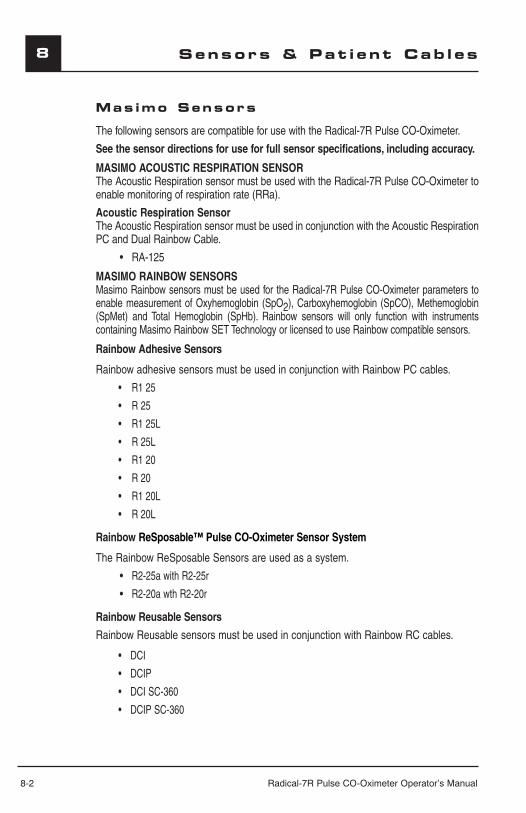
8-2 Radical-7R Pulse CO-Oximeter Operator’s Manual
8 Sensors & Pat i ent Cab l es
Mas imo Sensors
The following sensors are compatible for use with the Radical-7R Pulse CO-Oximeter.
See the sensor directions for use for full sensor specifications, including accuracy.
MASIMO ACOUSTIC RESPIRATION SENSORThe Acoustic Respiration sensor must be used with the Radical-7R Pulse CO-Oximeter to enable monitoring of respiration rate (RRa).
Acoustic Respiration Sensor The Acoustic Respiration sensor must be used in conjunction with the Acoustic Respiration PC and Dual Rainbow Cable.
• RA-125
MASIMO RAINBOW SENSORSMasimo Rainbow sensors must be used for the Radical-7R Pulse CO-Oximeter parameters to enable measurement of Oxyhemoglobin (SpO2), Carboxyhemoglobin (SpCO), Methemoglobin (SpMet) and Total Hemoglobin (SpHb). Rainbow sensors will only function with instruments containing Masimo Rainbow SET Technology or licensed to use Rainbow compatible sensors.
Rainbow Adhesive Sensors
Rainbow adhesive sensors must be used in conjunction with Rainbow PC cables.
R1 25•
R 25•
R1 25L•
R 25L•
R1 20•
R 20•
R1 20L•
R 20L•
Rainbow ReSposable™ Pulse CO-Oximeter Sensor System
The Rainbow ReSposable Sensors are used as a system.
• R2-25a with R2-25r
• R2-20a wth R2-20r
Rainbow Reusable Sensors
Rainbow Reusable sensors must be used in conjunction with Rainbow RC cables.
DCI•
DCIP•
DCI SC-360•
DCIP SC-360•

Radical-7R Pulse CO-Oximeter Operator’s Manual 8-3
8Sensors & Pat i ent Cab l es
Mas imo Sensors cont inued
Rainbow Direct Connect Sensors
Rainbow Direct Connect sensors connect to the instrument directly.
• DCI-dc3
• DCI-dc8
• DCI-dc12
• DCIP-dc3
• DCIP-dc8
• DCIP-dc12
• DC-3 SC360
• DC-12 SC360
• DCP-3 SC360
• DCP-12 SC360
• DC-3 SC200
• DCP-3 SC200
MASIMO SPO2 SENSORSThe Radical-7R may use standard Masimo LNOP, LNOPv and LNCS SpO2 sensors, when used with Red PC or Red LNC Patient Cables respectively. Select the appropriate patient cable to attach the LNOP or LNCS sensor to the instrument.
ReSposable™ Pulse CO-Oximeter Sensor System
The Rainbow ReSposable Sensors are used as a system.
• S2-25a with S2-25r
• S2-20a with S2-20r
Red Direct Connect Sensors
Masimo Red sensors can be used with the Radical-7R to enable measurement of SpO2 and pulse rate only. Red sensors will only function with Pulse CO-Oximeter instruments equipped with Masimo Rainbow SET technology. Red Direct Connect sensors connect to the instrument directly.
• DC-3
• DC-12
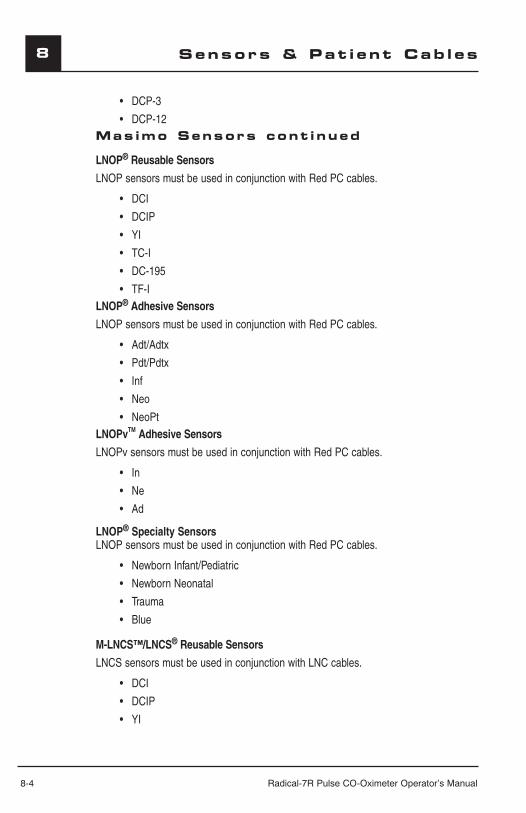
8-4 Radical-7R Pulse CO-Oximeter Operator’s Manual
8 Sensors & Pat i ent Cab l es
• DCP-3
• DCP-12Mas imo Sensors cont inued
LNOP® Reusable Sensors
LNOP sensors must be used in conjunction with Red PC cables.
• DCI
• DCIP
• YI
• TC-I
• DC-195
• TF-ILNOP® Adhesive Sensors
LNOP sensors must be used in conjunction with Red PC cables.
• Adt/Adtx
• Pdt/Pdtx
• Inf
• Neo
• NeoPtLNOPvTM Adhesive Sensors
LNOPv sensors must be used in conjunction with Red PC cables.
• In
• Ne
• Ad
LNOP® Specialty Sensors LNOP sensors must be used in conjunction with Red PC cables.
• Newborn Infant/Pediatric
• Newborn Neonatal
• Trauma
• Blue
M-LNCS™/LNCS® Reusable Sensors
LNCS sensors must be used in conjunction with LNC cables.
• DCI
• DCIP
• YI
Radical-7R Pulse CO-Oximeter Operator’s Manual 8-5
8Sensors & Pat i ent Cab l es
• TC-I
• TF-IMas imo Sensors cont inued
M-LNCS™/LNCS® Adhesive Sensors
LNCS sensors must be used in conjunction with Red LNC cables. • Adtx
• Pdtx
• Inf
• Neo
• NeoPt
• NeoPt-500M-LNCS™/LNCS® Specialty Sensors
LNCS specialty sensors must be used in conjunction with Red LNC cables.
• Newborn Infant/Pediatric

8-6 Radical-7R Pulse CO-Oximeter Operator’s Manual
8 Sensors & Pat i ent Cab l es
• Newborn Neonatal
• TraumaMas imo Sensors cont inued
SENSOR ACCURACY
See Sensor Directions for Use (DFU) for sensor accuracy specifications for: SpO2, SpMet, SpCO, SpHb, pulse rate and respiration rate.
CLEANING AND REUSE OF MASIMO REUSABLE SENSORS AND CABLESReusable sensors and patient cables can be cleaned per the following procedure:
1. Remove the sensor from the patient.
2. Disconnect the sensor from the patient cable.
3. Disconnect the patient cable from the monitor.
4. Wipe the entire sensor and/or patient cable clean with a 70% isopropyl alcohol pad.
5. Allow to air dry thoroughly before returning it to operation.
CAUTION: CAREFULLY ROUTE PATIENT CABLES TO REDUCE THE POSSIBILITY OF PATIENT ENTANGLEMENT OR STRANGULATION.
REATTACHMENT OF A SINGLE USE ACOUSTIC RESPIRATION SENSOR ■ A single use Acoustic Respiration sensor may be reapplied to the same patient if it is
dry, clean, free of debris and oil and the adhesive still adheres to the skin.
REATTACHMENT OF SINGLE USE ADHESIVE SENSORSSingle use sensors may be reapplied to the same patient if the emitter and detector windows are clear and the adhesive still adheres to the skin.
NOTE: If the sensor fails to track the pulse consistently, the sensors may be incorrectly positioned. Reposition the sensor or choose a different monitoring site.
CAUTION: DO NOT ATTEMPT TO REPROCESS, RECONDITION OR RECYCLE ANY MASIMO SENSORS OR PATIENT CABLES AS THESE PROCESSES MAY DAMAGE THE ELECTRICAL COMPONENTS, POTENTIALLY LEADING TO PATIENT HARM.
CAUTION: TO PREVENT DAMAGE, DO NOT SOAK OR IMMERSE THE SENSOR IN ANY LIQUID SOLUTION. DO NOT ATTEMPT TO STERILIZE BY IRRADIATION, STEAM, AUTOCLAVE OR ANY METHOD OTHER THAN ETHYLENE OXIDE AS INDICATED.
WARNING: TO AVOID CROSS CONTAMINATION ONLY USE MASIMO SINGLE USE SENSORS ON THE SAME PATIENT.
Radical-7R Pulse CO-Oximeter Operator’s Manual 9-1
9Serv i ce / Ma intenance
Introduct ion
This section covers: ■ How to properly clean the Radical-7R Pulse CO-Oximeter.■ How to recharge and replace the batteries.■ How to replace the fuses.■ How to obtain service.
Under normal operation, no internal adjustment or recalibration is required. Safety tests and internal adjustments should be done by qualified personnel only. Safety checks should be performed at regular intervals or in accordance with local and governmental regulations.
WARNING:ELECTRICAL SHOCK AND FLAMMABILITY HAZARD - BEFORE CLEANING THE PULSE CO-OXIMETER, ALWAYS TURN IT OFF AND DISCONNECT THE POWER CORD FROM THE AC POWER SUPPLY.
The Masimo Rainbow SET® Radical-7R Pulse CO-Oximeter is a reusable instrument. The instrument is supplied and used non-sterile.
Clean ingThe outer surface of the Masimo Rainbow SET® Radical-7R Pulse CO-Oximeter can be cleaned with a soft cloth dampened with a mild detergent and warm water solution. Do not allow liquids to enter the interior of the instrument. The outer surface of the instrument can also be wiped down using the following solvents: Cidex Plus (3.4% Glutaraldehyde), 10% Bleach, and 70% Isopropyl Alcohol.
■ DO NOT AUTOCLAVE, PRESSURE STERILIZE, OR GAS STERILIZE THE PULSE CO-OXIMETER.
■ DO NOT SOAK OR IMMERSE THE PULSE CO-OXIMETER IN ANY LIQUID.
■ USE THE CLEANING SOLUTION SPARINGLY. EXCESSIVE SOLUTION CAN FLOW INTO THE PULSE CO-OXIMETER AND CAUSE DAMAGE TO INTERNAL COMPONENTS.
■ DO NOT TOUCH, PRESS, OR RUB THE DISPLAY PANELS WITH ABRASIVE CLEANING COMPOUNDS, INSTRUMENTS, BRUSHES, ROUGH-SURFACE MATERIALS, OR BRING THEM INTO CONTACT WITH ANYTHING THAT COULD SCRATCH THE PANEL.
■ DO NOT USE PETROLEUM-BASED OR ACETONE SOLUTIONS, OR OTHER HARSH SOLVENTS, TO CLEAN THE PULSE CO-OXIMETER. THESE SUBSTANCES ERODE THE INSTRUMENT’S MATERIALS AND INSTRUMENT FAILURE CAN RESULT.
Refer to Section 8, Cleaning and Reuse of Masimo Sensors for cleaning instructions of the sensor.
9-2 Radical-7R Pulse CO-Oximeter Operator’s Manual
9
Battery Operat ion and Ma intenance
The Radical-7R Pulse CO-Oximeter Handheld includes a 1.5 Amp-Hour Nickel Metal Hydride battery. The Radical-7R Pulse CO-Oximeter Docking Station may include the optional 6.5 Amp-Hour Nickel Metal Hydride battery.
Before using the Radical-7R Pulse CO-Oximeter as a Handheld or transport monitor, the Handheld battery and the optional Docking Station battery need to be fully charged.
To charge the battery(s), attach the Handheld instrument to the Docking Station. Ensure that AC power is attached to the Docking Station. Verify that the battery(s) is charging; the battery charging LED indicators on the Docking Station flash prior to charging and remain illuminated while the battery(s) is charging. A continuously flashing battery charging LED indicates that the internal battery temperature exceeds recommended operating conditions for proper battery charging. Proper battery charging will proceed when the temperature returns to recommended operating conditions.
The Handheld battery requires approximately 2 to 3 hours for charging. The optional Docking Station battery requires approximately 6 hours for charging.
When the battery charging LED indicators turn off, additional trickle charging may occur to complete charging. Although battery charging can occur while the Handheld is docked and powered on, most efficient charge times are achieved with the Handheld instrument turned off.
CAUTIONS:
■ ALL BATTERIES LOSE CAPACITY WITH AGE, THUS THE AMOUNT OF RUN TIME LEFT AT LOW BATTERY WILL VARY DEPENDING UPON THE AGE OF THE BATTERY.
■ AT LOW BATTERY CONNECT THE RADICAL-7R PULSE CO-OXIMETER TO AC POWER TO PREVENT LOSS OF POWER.
During battery operation of the Radical-7R Pulse CO-Oximeter, please note that the following operating conditions affect the estimated run-time of the included batteries:
■ VOLUME OF THE ALARM TONES. TO CONSERVE BATTERY POWER, KEEP THE FREQUENCY OF THE AUDIBLE ALARMS TO A MINIMUM AND AT MINIMUM VOLUME.
Memory effects of the battery pack may shorten run-time. When battery run-time is significantly reduced, it is advisable to completely discharge and fully recharge the battery pack. To properly discharge the battery pack, use the Battery Discharge function as described in Section 4, under Service.
CAUTION:■ IF THE RADICAL-7R PULSE CO-OXIMETER HANDHELD HAS NOT BEEN USED OR
CHARGED WITHIN SEVEN (7) DAYS OR MORE, THEN RECHARGE THE BATTERY PRIOR TO USE.
■ IT IS RECOMMENDED THAT THE RADICAL-7R PULSE CO-OXIMETER HANDHELD IS DOCKED TO THE DOCKING STATION ATTACHED TO AN AC POWER SOURCE WHEN IT IS NOT IN USE TO ENSURE THAT THE BATTERY REMAINS FULLY CHARGED.
The following tables outline the estimated run times of the battery powered Radical-7R Pulse CO-Oximeter. The time estimates are based on a Radical-7R Pulse CO-Oximeter with fully charged batteries. The Radical-7R Pulse CO-Oximeter is always configured to include the Handheld battery. It may optionally be configured to include the Docking Station battery. Please determine the configuration of your system before referencing the following tables.
Serv i ce / Ma intenance
Radical-7R Pulse CO-Oximeter Operator’s Manual 9-3
9
CONFIGURATION #1:Radical-7R Pulse CO-Oximeter configured to only include the Handheld battery (standard configuration); the Docking Station battery is excluded.
NOTE: For this configuration, it is advisable to operate only the Radical-7R Handheld instrument when running on battery power. Although it is possible to operate the entire Standalone instrument (the Handheld attached to the Docking Station, with the Handheld battery powering the Docking Station as well) on battery power, the capacity of the Handheld battery pack is insufficient to support this mode for long periods of time.
RADICAL-7R CONFIGURATION MINIMUM RUN-TIME
HANDHELD ONLY 1 hr
CONFIGURATION #2:Radical-7R configured to include the Handheld and the Docking Station battery:
RADICAL-7R CONFIGURATION MINIMUM RUN-TIME
HANDHELD AND DOCKING STATION 6 hr
REPLACING THE BATTERIES
Before installing or removing the battery, make sure the AC power cord is removed and power to the Pulse CO-Oximeter is turned off.
To replace the Handheld battery, follow these instructions:1. Turn the Radical-7R Pulse CO-Oximeter Handheld off and remove the patient cable
connection. Detach the Radical-7R Pulse CO-Oximeter Handheld from the Docking Station (if docked).
2. Loosen the closure screw on the battery compartment door and lift out the battery.3. Take a new battery, and place it in the compartment. 4. Tighten the closure screw.5. Place Handheld into Docking Station, turn on line power and charge battery according to
this Section, Battery Operation and Maintenance.
CAUTION: FOLLOW LOCAL GOVERNING GUIDELINES FOR PROPER DISPOSAL OF INTERNAL BATTERIES. DO NOT INCINERATE.
WARNING: THE DOCKING STATION BATTERY SHOULD BE INSTALLED AND/OR REMOVED FROM DOCKING STATION BY QUALIFIED PERSONNEL ONLY.
REPLACING THE FUSES
Should a power problem blow one or both of the fuses in the power entry module on the rear panel, the fuse(s) will need to be replaced.
Serv i ce / Ma intenance
Battery Operat ion and Ma intenance ( cont inued )
9-4 Radical-7R Pulse CO-Oximeter Operator’s Manual
9 Serv i ce / Ma intenance
To replace the fuse(s), you will need a flat-blade screwdriver (5mm; 3/16”).
To replace the fuses:
1. Disconnect instrument from AC power.2. Remove AC power cord from the power entry module at the rear of the docking station.3. Use the small flat-blade screwdriver and gently pry loose the fuse cover in the left portion
of the power entry module, exposing the fuse holder.4. Using the small flat-blade screwdriver, gently remove the fuse holder.5. Note how the fuse(s) are placed in the fuse holder for installation of the new fuse(s).6. To remove the fuses from the fuse holder, use the edge of the screwdriver blade to pry
against the bottom of the metal portion of the fuse where it is secured to the glass portion of the fuse.
7. Place the fuse(s) (1 Amp, Metric, fast acting, 5x20mm, 250V) in the fuse holder, properly orienting the fuse(s).
8. Slide the fuse holder back into the power entry module and press firmly to make sure it is completely seated.
9. Close the fuse cover and press gently until it seats completely, flush with the back of the docking station.
10. The instrument is ready to be reconnected to AC power.
NOTE: If the fuses blow shortly after replacement, the instrument requires service.
WARNING: FIRE HAZARD: TO PROTECT AGAINST FIRE HAZARD, REPLACE ONLY WITH FUSES OF THE SAME TYPE, CURRENT RATING, AND VOLTAGE RATING.
Per formance Ver i f i cat i onTo test the performance of the Radical-7R Pulse CO-Oximeter following repairs or during routine maintenance, follow the procedure outlined in this section. If the Radical-7R Pulse CO-Oximeter fails any of the described tests, discontinue its use and correct the problem before returning the instrument back to the user.
Before performing the following tests place the Radical-7R Pulse CO-Oximeter Handheld into the Docking Station, connect the Radical-7R to AC power and fully charge the Radical-7R Pulse CO-Oximeter Handheld battery. Also disconnect any patient cables or pulse oximetry probes, as well as SatShare, serial or analog output cables from the instrument. Set the Radical-7R Pulse CO-Oximeter to normal operating mode by selecting the Home Use parameter in the General Menu to “No”.
Power-On Self-Test:1. Connect the monitor to AC power and verify that the AC Power Indicator is lit.2. Turn the monitor on by depressing the Power/Standby Button. Within 5 seconds all available
LEDs are illuminated, a 1-second beep tone sounds, and the Masimo SET logo is displayed. 3. The blue Docking Indicator LED is illuminated and the Radical-7R begins normal
operation.
Alarm Limit Test:
Radical-7R Pulse CO-Oximeter Operator’s Manual 9-5
9Serv i ce / Ma intenance
1. With the monitor turned on, select the Menu Access key and enter the Alarm menu. Change the High SpO2 Alarm parameter to a value two points below the currently selected value, and accept the change.
2. Verify that the newly set parameter is shown on the Saturation Alarm Limit Display, next to the SpO2 or pulse rate measurement display.
3. Return the High Saturation Alarm parameter to its original setting.4. Repeat steps 1 to 3 for the following alarm parameters:
■ Low SpO2 ■ High and Low Pulse Rate
■ High and Low Respiration Rate (RRa)
■ High SpMet
■ High SpCO
■ High and Low SpHb ■ PI ■ PVI
5. Reset the alarm limits again to the original settings.
Testing with Masimo SET Tester (Optional): 1. Turn the Radical-7R off and then on again.2. Connect the Masimo SET Tester to the Pulse CO-Oximeter Patient Cable Connector. Refer
to the Masimo SET Tester's Directions for Use for further instructions.
Nurse Call Test:1. Disconnect the Red patient cable or the Masimo SET Tester from the Radical-7R and turn
the instrument on. Ensure that there are no audible alarms and that the audible alarms are not silenced. Verify the nurse call polarity is set to normal (default).
2. Connect the common lead of a digital multi-meter to the pin 12 (Nurse Call - Common) of the analog output connector on the Radical-7R. Connect the positive lead of the multi-meter to pin 6 (Nurse Call - Normally Open) of the analog output connector and measure that the resistance is greater than 1 MW (open circuit).
3. Trigger an alarm on the monitor (e.g. by disconnecting a sensor after it was measuring data) and verify that the resistance is less than 35 ohms.
Analog Output Test
1. Disconnect all patient cables and sensors from the Radical-7R. Turn the Radical-7R off and then on again.
2. Connect the common lead of a digital voltmeter to the pin 2 (Ground) of the analog output connector on the Radical-7R Connect the positive lead of the voltmeter to pin 9 (Analog 1) of the analog output connector.
3. Enter the menu system and set the “Output”, “Analog 1” to “0V Signal”. Verify that the voltmeter measures a voltage of approximately 0V.
4. Enter the menu system and set the “Output”, “Analog 1” to “1V Signal”. Verify that the voltmeter measures a voltage of approximately 1.0V.
5. Repeat Steps 3 and 4, with the positive lead of the voltmeter connected to pin 15 (Analog 2).
9-6 Radical-7R Pulse CO-Oximeter Operator’s Manual
9 Serv i ce / Ma intenance
6. Connect a patient cable and sensor and verify that the voltage on pins 9 and 15 are between 0V and 1.0V while measuring a saturation and pulse rate.
Battery Test:1. Fully charge the Radical-7R by placing the Handheld into the Docking Station and
connecting the AC power. 2. Verify that the green Handheld Battery Indicator LED is illuminated.3. When the Radical-7R is fully charged the green Handheld Battery Indicator turns off.
4. Turn the Radical-7R on and verify that the Battery indicator shows a full charge.
Service and RepairREPAIR POLICYMasimo or an authorized Service Department must perform warranty repair and service. Do not use malfunctioning equipment. Have the instrument repaired.
WARNING: DO NOT REMOVE THE COVER OF THE MONITOR EXCEPT FOR BATTERY REPLACEMENT. AN OPERATOR MAY ONLY PERFORM MAINTENANCE PROCEDURES SPECIFICALLY DESCRIBED IN THIS MANUAL. REFER SERVICING TO QUALIFIED SERVICE PERSONNEL TRAINED IN THE REPAIR OF THIS EQUIPMENT.
Please clean contaminated and/or dirty equipment before returning, following the cleaning procedure described in Section 9, Cleaning. Make sure the equipment is fully dry before packing.
To return the Radical-7R instrument for service, please follow the Return Procedure.
RETURN PROCEDURE
Please clean contaminated/dirty equipment before returning. Make sure the equipment is fully dry before packing. Call Masimo at 800-326-4890 and ask for Technical Support. Ask for an RMA number. Package the equipment securely – in the original shipping container if possible – and enclose or include the following information and items:
■ A letter describing in detail any difficulties experienced with the Pulse CO-Oximeter. Please include the RMA number in the letter.
■ Warranty information – a copy of the invoice or other applicable documentation must be included.
■ Purchase order number to cover repair if the Pulse CO-Oximeter is not under warranty, or for tracking purposes if it is.
■ Ship-to and bill-to information.
■ Person (name, telephone/Telex/fax number, and country) to contact for any questions about the repairs.
■ A certificate stating the Pulse CO-Oximeter has been decontaminated for bloodborne pathogens.

Radical-7R Pulse CO-Oximeter Operator’s Manual 9-7
9Serv i ce / Ma intenance
Return Radical-7R Pulse CO-Oximeter to the following shipping address:
For USA, Canada & Asia Pacific: For Europe: All other locations:
Masimo Corporation40 ParkerIrvine, California 92618949-297-7000FAX 949-297-7001
Masimo International SàrlPuits-Godet 102000 Neuchatel - SWITZERLANDTel: +41 32 720 1111Fax.: +41 32 724 1448
Contact your local Masimo Representative.
9-8 Radical-7R Pulse CO-Oximeter Operator’s Manual
9 Serv i ce / Ma intenance
Sales & End-User License Agreement
THIS DOCUMENT IS A LEGAL AGREEMENT BETWEEN YOU (“PURCHASER”) AND MASIMO CORPORATION (“MASIMO”) FOR THE PURCHASE OF THIS PRODUCT (“PRODUCT”) AND A LICENSE IN THE INCLUDED OR EMBEDDED SOFTWARE (“SOFTWARE”). EXCEPT AS OTHERWISE EXPRESSLY AGREED IN A SEPARATE CONTRACT FOR THE ACQUISITION OF THIS PRODUCT, THE FOLLOWING TERMS ARE THE ENTIRE AGREEMENT BETWEEN THE PARTIES REGARDING YOUR PURCHASE OF THIS PRODUCT. IF YOU DO NOT AGREE TO THE TERMS OF THIS AGREEMENT, PROMPTLY RETURN THE ENTIRE PRODUCT, INCLUDING ALL ACCESSORIES, IN THEIR ORIGINAL PACKAGES, WITH YOUR SALES RECEIPT TO MASIMO FOR A FULL REFUND. WarrantyMasimo warrants to the initial Purchaser for a period of one (1) year from the date of purchase that: (i) each new Product and the Software media as delivered are free from defects in workmanship or materials, and (ii) the Product and Software will perform substantially as labeled in the directions for use. Masimo’s sole obligation under this warranty is to repair or replace any Product or Software that is covered under warranty. Batteries are warranted for six (6) months.To request a replacement under warranty, Purchaser must contact Masimo for a returned goods authorization. If Masimo determines that a Product must be replaced under warranty, it will be replaced and the cost of shipment covered. All other shipping costs shall be the responsibility of Purchaser.
Exc lus ionsThe warranty does not extend to, and Masimo is not responsible for, repair, replacement, or maintenance needed because of: a) modification of the Product or Software without Masimo’s written authorization; b) supplies, instruments or electrical work external to the Product or not manufactured by Masimo; c) disassembly or reassembly of the Product by anyone other than an authorized Masimo agent; d) use of the Product with sensors or other accessories other than those manufactured and distributed by Masimo; e) use of the Product and Software in ways or in environments for which they are not labeled; and f) neglect, misuse, improper operation, accident, fire, water, vandalism, weather, war, or any act of God. This warranty does not extend to any Product that has been reprocessed, reconditioned or recycled.This warranty also does not apply to any Products provided to Purchaser for testing or demonstration purposes, any temporary Products modules or any Products for which Seller does not otherwise receive a usage or purchase fee; all such Products are provided AS-IS without warranty.
THIS WARRANTY, TOGETHER WITH ANY OTHER EXPRESS WRITTEN WARRANTY THAT MAY BE ISSUED BY MASIMO IS THE SOLE AND EXCLUSIVE WARRANTY AS TO THE PRODUCT AND SOFTWARE. THIS WARRANTY IS EXPRESSLY IN LIEU OF ANY ORAL OR IMPLIED WARRANTIES, INCLUDING WITHOUT LIMITATION ANY IMPLIED WARRANTY OF MERCHANTABILITY OR FITNESS FOR A PARTICULAR PURPOSE. MASIMO SHALL NOT BE LIABLE FOR ANY INCIDENTAL, SPECIAL OR CONSEQUENTIAL LOSS, DAMAGE OR EXPENSE DIRECTLY OR INDIRECTLY ARISING FROM THE USE OR LOSS OF USE OF ANY PRODUCTS OR SOFTWARE. IN NO EVENT SHALL MASIMO’S LIABILITY ARISING FROM ANY PRODUCT AND SOFTWARE (UNDER CONTRACT, WARRANTY, TORT, STRICT LIABILITY OR OTHER CLAIM) EXCEED THE AMOUNT PAID BY PURCHASER FOR THE PRODUCTS GIVING RISE TO SUCH CLAIM. THE LIMITATIONS IN THIS SECTION SHALL NOT BE DEEMED TO PRECLUDE ANY LIABILITY THAT CANNOT LEGALLY BE DISCLAIMED BY CONTRACT.

Radical-7R Pulse CO-Oximeter Operator’s Manual 9-9
9
End -User L i cense Agreement1. Grant of License: In consideration of payment of the Software license fee, which is part of the
price paid for the Product, Masimo grants to Purchaser a nonexclusive, nontransferable (except as set forth below) license (“License”), without right to sublicense, to use the copy of the Software in connection with Purchaser’s use of the Product for its labeled purpose as set forth in these directions for use. Masimo reserves all rights not expressly granted to Purchaser.
2. Ownership of Software: The Software is licensed not sold; all rights and interests in the Software and all copies thereof remain at all times vested in Masimo, and do not pass to Purchaser. Any references in this Agreement to the purchase or sale of the Software shall be deemed the purchase or sale of a Software License as set forth herein.
Restr i c t i ons1. Copyright Restrictions: The Software and the accompanying written materials are copyrighted.
Unauthorized copying of the Software, including Software that has been modified, merged, or included with other software, or the written materials is expressly forbidden. Purchaser may be held legally responsible for any copyright infringement that is caused or incurred by Purchaser’s failure to abide by the terms of this Agreement. Nothing in this License provides any rights beyond those provided by 17 U.S.C. §117.
2. Use Restrictions: Purchaser may physically transfer the Product from one location to another provided that the Software is not copied. Purchaser may not electronically transfer the Software from the Product to any other instrument. Purchaser may not disclose, publish, translate, release, distribute copies of, modify, adapt, translate, reverse engineer, decompile, disassemble, or create derivative works based on the Software or the written materials.
3. Transfer Restrictions: In no event may Purchaser transfer, assign, rent, lease, sell, or otherwise dispose of the Product or the Software on a temporary basis. Purchaser shall not assign or transfer this License, in whole or in part, by operation of law or otherwise without Masimo's prior written consent; except that the Software and all of Purchaser’s rights hereunder shall transfer automatically to any party that legally acquires title to the Product with which this Software is included. Any attempt to assign any rights, duties or obligations arising hereunder other than as set forth in this paragraph shall be void.
4. U.S. Government Rights: If Purchaser is acquiring Software (including the related documentation) on behalf of any part of the United State Government, the following provisions apply: the Software and documentation are deemed to be “commercial software” and “commercial computer software documentation,” respectively pursuant to DFAR Section 227.7202 FAR 12.212, as applicable. Any use, modification, reproduction, release, performance, display or disclosure of the Software (including the related documentation) by the U.S. Government or any of its agencies shall be governed solely by the terms of this Agreement and shall be prohibited except to the extent expressly permitted by the terms of this Agreement.
No Imp l i ed L i cense
Possession or purchase of this device does not convey any express or implied license to use the device with unauthorized sensors or cables that would, alone, or in combination with the device, fall within the scope of one or more of the patents relating thereto. BY ACCEPTANCE OR USE OF THIS DEVICE, YOU ACKNOWLEDGE YOUR ACCEPTANCE OF THESE TERMS.
Serv i ce / Ma intenance
9-10 Radical-7R Pulse CO-Oximeter Operator’s Manual
9
Sensors L icensed for Monitor ing Use Only
Sensors designated for monitoring only are licensed to you under patents owned by Masimo to be used for patient monitoring, in an unmodified form as originally received from Masimo, and no license is granted to have Masimo’s sensors reprocessed or otherwise modified, unless specifically authorized by Masimo. There is no license, implied or otherwise, that would allow use of licensed sensors beyond their intended duration. After use of sensors through their designated duration, there is no further license granted by Masimo to use the sensors and the sensors must be discarded or returned to Masimo for reprocessing.
Serv i ce / Ma intenance

Radical-7R Pulse CO-Oximeter Operator’s Manual 10-1
10Part Numbers
PART NUMBER DESCRIPTION2386 REPLACEMENT BATTERY, RADICAL-7R HANDHELD
1317 RADICAL-7R POLE CLAMP
2350 RADICAL-7R HANDHELD LOCK
2351 RADICAL-7R HANDHELD LOCK KEY
2368 MASIMO SET TESTER - 20 PIN
1584 RADICAL-7R POWER CORD LOCK, 5/PACK
Please visit our website, www.masimo.com, for updated information about Masimo products.

www.masimo.comInstruments and sensors containing Masimo Rainbow SET technology are
identified with the Masimo Rainbow SET logo. 3397
5/61
89A
-120
9