ptr54124 gx630-690 match manual · honda-designed equipment integrates the engine to match the load...
TRANSCRIPT

GX630GX660GX690
Technical Manual
PTR54124-A©2010 American Honda Motor Co., Inc.All Rights Reserved


GX630 • GX660 • GX690 Technical Manual
© 2010 American Honda Motor Co., Inc — All Rights Reserved 1
PrefaceThis manual covers engine selection, engine installation design, and engine installation testing so the combination of a Honda engine and your equipment will make the best possible product.
Please feel free to contact your Honda Engine Distributor at any time for additional technical information or to discuss your engine application needs.
All information contained in this manual is based on the latest product information available at the time of printing. We reserve the right to make changes at anytime without notice.
No part of this publication may be reproduced, or transmitted, in any form or by any means, electronic, mechanical photocopying, recording or otherwise, without the prior written permission of the publisher. This includes text, figures and tables.
ContentsIntroduction ................................................................. 2Design Features .......................................................... 2Emission Regulations ................................................. 2Recommended Power Range ..................................... 3
Maximum Operation ............................................... 3Continuous Operation ............................................ 3Power Curves ........................................................ 3Output Confirmation Methods ................................ 5
Cooling ....................................................................... 5Minimum Cooling Air Flow Requirement ................ 5Ambient Temperature Limits .................................. 5Testing ................................................................... 5Engine Enclosures ................................................. 6
Fuel System ................................................................ 7Fuel Tank Position ................................................. 7Fuel Line ................................................................. 7Fuel Valve .............................................................. 7Fuel Pump ............................................................. 7Fuel Tank Filter Installation .................................... 7Fuel-cut Solenoid ................................................... 7
Controls ....................................................................... 7Engine Switch ........................................................ 7Carburetor Controls ............................................... 8
Exhaust System .......................................................... 9Recommended Muffler ........................................... 9Fabricated Exhaust Systems ................................. 9
Engine Mounting ....................................................... 10Inclination ............................................................. 10Resonance Check ............................................... 10
Electrical System ...................................................... 12Battery ................................................................ 12Fuse ..................................................................... 12Battery Cables ..................................................... 12Engine Switch ...................................................... 12Charging Coil Selection ....................................... 13Oil Alert® System (optional) ................................ 13Oil Pressure Switch .............................................. 13Wiring Precautions ............................................... 13
Wiring Diagrams ....................................................... 142.7A Charging systems - Remote Control Type .. 14Control Box Type ................................................. 1417A Charging Systems - Remote Control Type ... 15Control Box Type ................................................. 15
26A Charging System ..........................................16Power Transmission ..................................................16
V-Belt Connections ...............................................16Front PTO Shaft Output ........................................18Starting Performance ...........................................18
Installation Considerations ........................................19Maintenance Points Accessibility ........................19
Dimensional Drawings ...............................................20Side Mount Muffler ...............................................21High Mount Muffler ...............................................21Mounting and PTO Shaft Drawings ......................22
Dimensions and Weights ...........................................24Specifications ............................................................25Serviceability .............................................................25Evaporative emissions (CARB Tier 3) .......................31

GX630 • GX660 • GX690 Technical Manual
2 © 2010 American Honda Motor Co., Inc — All Rights Reserved
INTRODUCTION
Honda engines are designed for minimal maintenance. When maintenance is required, the task is kept simple by providing convenient maintenance access and procedures.
Honda engines use proven engine technology and design innovations to make them the most reliable engines.
DESIGN FEATURES
High PerformanceThe new design one-piece head/cylinder provides increased combustion efficiency and cylinder cooling capacity, allowing for higher compression and higher engine output. Combustion efficiency has been improved through the use of a hemispherical combustion chamber with the spark plug placed closer to the center of the chamber. Cooling efficiency has been increased by combining the cylinder barrel and head, and providing external push rod tubes.
Smooth and Quiet OperationOHV design provides a reduced reciprocating mass and balanced weight distribution. These features and the compact design result in extremely smooth operation.
Use of proven design technologies reduces noise from internal engine components. The hardness of reciprocating parts, the helical cut gears on the crankshaft and camshaft, and the use of select materials makes these engines exceptionally quiet. The optional large mufflers are designed to further reduce noise.
Durability/ReliabilityHonda engines are built with quality that provides proven durability and reliability. Proven features such as OHV design and cast iron cylinder sleeve provide long life in all types of operating conditions. To further enhance the reliability of these engines, a 2-stage air cleaner system, electronic ignition system, mechanical centrifugal governor, and proven side-draft carburetor are standard features.
EMISSION REGULATIONS
The Honda GX630, GX660, and GX690 engines meet U.S. Environmental Protection Agency and the California Air Resources Board regulations when fitted with a certified fuel delivery system and either a Honda genuine muffler or a certified muffler.
Honda-designed equipment integrates the engine to match the load and packaging requirements of both the engine and the product. Honda engine distributors and equipment manufacturers that use Honda engines are required by regulation to follow this OEM technical manual. Correct engine matching ensures that the engine will be durable (and emissions durable) in use.
Refer to the Honda Emission Regulation Guide (TO971) for additional emissions information.
GX690

GX630 • GX660 • GX690 Technical Manual
© 2010 American Honda Motor Co., Inc — All Rights Reserved 3
RECOMMENDED POWER RANGE
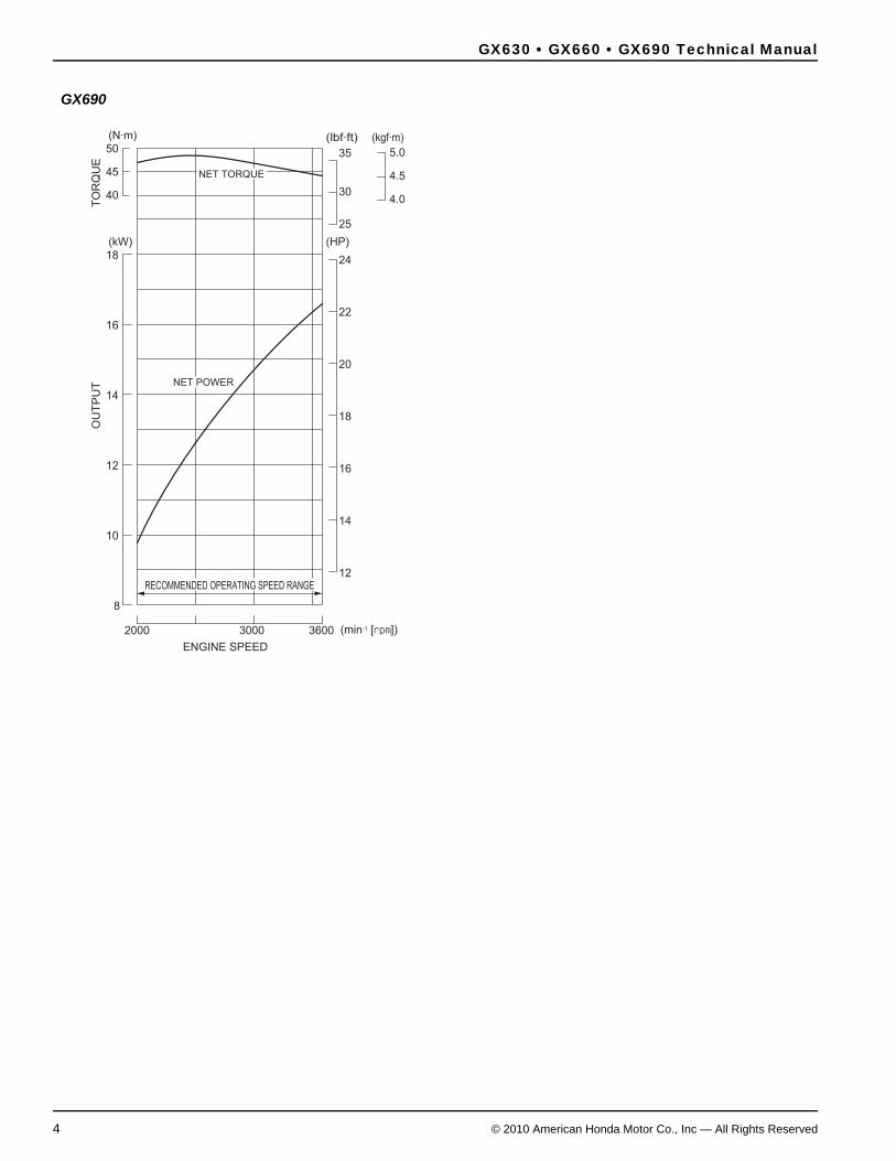
Maximum OperationOperate the engine at not more than 90% of the maximum horsepower available at a given rpm.
Recommended maximum operating bhp = 0.9 x maximum bhp
Continuous OperationFor continuous operation (more than 30 minutes), operate the engine at not more than 80% of the maximum horsepower available at a given rpm.
Continuous recommended operating bhp = 0.8 x maximum bhp
Power CurvesGX630 GX660
(N·m)
50
(kW) (HP)
(lbf·ft) (kgf·m)
18
16
14
OU
TP
UT
ENGINE SPEED
(min-1 [rpm])
TO
RQ
UE
12
12
25
4.0
4.5
5.0
30
35
14
16
18
20
22
24
10
8
2000 36003000
45
40
RECOMMENDED OPERATING SPEED RANGE
NET POWER
NET TORQUE
(N·m)
50
(kW) (HP)
(lbf·ft) (kgf·m)
18
16
14
12
12
25
4.0
4.5
5.0
30
35
14
16
18
20
22
24
10
8
2000 36003000
45
40
TO
RQ
UE
RECOMMENDED OPERATING SPEED RANGE
NET POWER
NET TORQUE
OU
TP
UT
ENGINE SPEED
(min-1 [rpm])
GX630 • GX660 • GX690 Technical Manual
4 © 2010 American Honda Motor Co., Inc — All Rights Reserved
GX690
(N·m)
50
(kW) (HP)
(lbf·ft) (kgf·m)
18
16
14
12
12
25
4.0
4.5
5.0
30
35
14
16
18
20
22
24
10
8
2000 36003000
45
40
TO
RQ
UE
RECOMMENDED OPERATING SPEED RANGE
NET POWER
NET TORQUE
OU
TP
UT
ENGINE SPEED
(min-1 [rpm])

GX630 • GX660 • GX690 Technical Manual
© 2010 American Honda Motor Co., Inc — All Rights Reserved 5
Output Confirmation Methods
Governor Rod MeasurementWhen the engine is properly matched and operating at its continuous rated load, the carburetor throttle angle should be approximately half way between full open and full closed positions.
Bring the engine to normal operating temperature and then apply the expected continuous load. If the throttle is more than halfway open, the engine is being overloaded resulting in overheating and shortened engine life.
Tachometer RPM MeasurementNormal governor droop can also be used to measure engine load.
At rated speed:
Engine is operating within the continuous recommended power range.
COOLING
Minimum Cooling Air Flow Requirement22 m3
(777 ft3) per minute at 3,600 rpmEngine enclosure must have the minimum cooling airflow listed above.
Ambient Temperature Limits-25 to +40°C (-13 to +104°F)
Testing· Use thermocouple temperature probes at the specified locations.
· Operate the engine under worst-case conditions.
· An electronic data logger is recommended for the temperature data collection.
· Set up the data logger to take multiple readings per minute. If data is being taken manually, a reading every 5 minutes is adequate.
· Take readings until the engine temperature is stabilized at continuous rated load.
· Run the application for one hour of continuous operation; the temperatures should be stabilized in that time. If the application is used only for short intervals, note the normal run time in the application document.
· Shut the engine down and continue to take readings. Attempt to restart the engine after heat soaking.
Maximum Operating Temperatures
These temperatures are based on a maximum ambient temperature of 40°C (104°F). Compensate for any deviation linearly; i.e., if the ambient temperature is 20°C (68°F), the maximum acceptable oil temperature is 120°C (248°F).
Spark plug seat 250 °C (482 °F)Engine oil 140 °C (284 °F)Gasoline at carburetor float bowl 60 °C (140 °F)Gasoline at maximum soak 70 °C (158 °F)Gasoline at fuel tank 60 °C (140 °F)
rpm with load
rpm without load1-( )100% ≤ 5%

GX630 • GX660 • GX690 Technical Manual
6 © 2010 American Honda Motor Co., Inc — All Rights Reserved
Engine Enclosures
Cool Air IntakeThe engine must be provided with a cooling duct so that fresh air can be drawn directly from outside the enclosure cover. Install the cooling air duct with the intake port in a place free from dust and dirt. The cooling air volume changes according to the shape of the duct and screen and the engine installation conditions. Operate the engine under the normal operating conditions and be sure that the engine meets all temperature requirements.
The cooling air duct must have a cross-sectional area of at least 300 cm2 (46.5 sq. in).
When the engine is operated in dusty areas, install a filter at the enclosure inlet for the cooling air. This will reduce the effective area, so you must increase the size of the inlet accordingly. Increase the size of the inlet to the point where the maximum operating temperatures are not exceeded when operated under maximum load.
Install the cooling air duct and filter so that the filter can be easily checked and dust, dirt, and foreign material removed.
Front PTO Output Shaft PulleyWhen installing a front output pulley, make sure there is sufficient space between the pulley and screen grid or fan cover protector to enable the cooling air to flow unimpeded. The recommended distance from the pulley to the fan grid should be approximately 1/3 the diameter of the pulley. If the outside diameter (O.D.) is 150 mm, leave a space of about 45 mm. Always perform a practical test, confirming that the temperature of each part conforms to the temperature requirement.
Hot Air DischargeHot air must be discharged directly outside the enclosure. Provide a discharge duct if necessary. The minimum cross section of the hot air discharge opening must be larger than that of the cooling air inlet.
Locate the discharge port so the hot discharge air does not flow back into the enclosure. Provide sufficient ventilation to prevent the engine compartment temperature from rising above ambient temperature limits after the engine has been stopped.
Exhaust DischargeThe exhaust system becomes hot during operation and remains hot for a while after operation. Separate the exhaust system from the engine compartment with a partition wall and locate the exhaust system in the discharged cooling air flow.
Be sure the exhaust gas is directly discharged outside the enclosure without being blocked or restricted by any obstacles. The exhaust gas must not flow back or be drawn back into the enclosure.
Provide the engine with an exhaust deflector or exhaust pipe extension if necessary.
If an extension pipe is used:
· Keep the length of the pipe as short as possible to keep exhaust back pressure within limits (see page 10).
· The extension pipe must have an ID larger than the OD of the muffler outlet.
· Verify the exhaust pipe extension does not create excessive vibration at any given engine rpm. If necessary, use an exhaust pipe holder to support the exhaust pipe extension.
Grass Cutting ApplicationsWhen the engine is operated on grass cutting equipment, install a rotary screen grid on the cooling air intake port to prevent the accumulation of large clippings.
Do not allow the grass clippings shredded by the rotary screen grid to accumulate around the intake port.
45 mm
150 mm

GX630 • GX660 • GX690 Technical Manual
© 2010 American Honda Motor Co., Inc — All Rights Reserved 7
FUEL SYSTEM
This engine is supplied with an incomplete fuel system (no fuel tank, no fuel hose, etc.). As such, the OEM is responsible for ensuring evaporative emission regulations are met.
Fuel Tank PositionThe fuel tank must be installed so that its maximum gasoline level is within 50 cm (19.5 in) above or below the carburetor gasoline level.
Fuel LineUse a low permeation fuel line (displaying an Executive Order number) rated for use with gasoline. The fuel line should have an inside dimension of 5.5 mm (0.22 in). Keep the fuel line as short as possible. Install the fuel line so it will not rest against any sharp objects or make sharp bends that can restrict the flow of fuel. If the fuel line passes through an enclosure wall, protect the line with a rubber grommet. Secure the fuel line with the appropriate clamping mechanism.
Route the fuel line away from hot engine and exhaust system components and away from electrical wiring. Secure the fuel line to prevent sagging and bending.
Fuel ValveInstall the fuel valve so it is easily accessible. Install the fuel valve at the outlet of the fuel tank and use an easily read label to indicate valve location and operation. If under the fuel tank is not the ideal location, securely install the fuel valve in-line with the fuel tube in a cool location, so that engine heat cannot cause vapor lock.
Fuel PumpA fuel pump should be selected that provides an operating pressure of 0.1 kgf/cm2 (1.4 psi) and delivers 15 liters/hr (4.0 US gal/hr). The carburetor inlet float valve has a closing pressure of 0.2 kgf/cm2 (2.8 psi). If a secondary fuel pump is used, its operating pressure must not exceed the standard fuel pump’s operating pressure (to prevent carburetor flooding).
Fuel Tank Filter InstallationIt is recommended that a fuel tank strainer with a mesh rating of #80 be installed at the fuel tank inlet to catch debris when refueling. It is also recommended that a fuel tank sump be provided at the fuel tank outlet to reduce the chance of contaminants entering the fuel system.
Fuel-cut SolenoidThe fuel-cut solenoid on the carburetor takes power from the battery and there is continuity in the solenoid when the engine is running. Removing the battery when the engine is running will cause the engine to stop.
CONTROLS
Engine SwitchUse a three-position engine switch with continuity between its terminals as shown.
Wire (Color) IGN(Bl)
GND(G)
BAT(W)
LO(Bl/Y)
ST(Bl/W)Switch Position
OFF
ON
START

GX630 • GX660 • GX690 Technical Manual
8 © 2010 American Honda Motor Co., Inc — All Rights Reserved
Carburetor ControlsInstallation direction:
Cable may be installed either on the left or right side.
Types of cable:Two types can be used, braided wire or solid wire.
Remote Control Throttle and Choke
LEFT SIDE CONTROL RIGHT SIDE CONTROL
CHOKE CONTROLLEVER
GOVERNOR SPRING
CABLE HOLDER (2)
THROTTLE CONTROLLEVER
THROTTLE CABLE
CHOKE CABLE
CABLE
5 x 16 mm (2)
4 x 6 mm
CHOKE CONTROLLEVER
GOVERNOR SPRING
CABLEHOLDER (2)
THROTTLE CONTROL LEVER
CABLE
CHOKE CABLETHROTTLE CABLE
WIRE HOLDER
5 x 16 mm (2)
4 x 6 mm
GX630 • GX660 • GX690 Technical Manual
© 2010 American Honda Motor Co., Inc — All Rights Reserved 9
EXHAUST SYSTEM
Recommended MufflerHonda mufflers and exhaust pipes are matched to the engine in terms of emissions performance, exhaust back pressure, silencing performance, durability, and installation rigidity.
Consider the following:
· Discharge the exhaust gas directly to the open air. Do not install flammable parts or any parts with poor heat resistance properties around the exhaust system or near the discharge port.
· The exhaust gas must not enter the cooling-air intake port. Be especially careful when using the exhaust deflector to change the discharge direction.
· The muffler and exhaust pipe become very hot during operation and remain hot after the engine has been shut off. Install the muffler and exhaust pipe so the fuel system and other heat-sensitive components are isolated from the exhaust heat.
Fabricated Exhaust SystemsThe muffler type and the shape and length of the exhaust pipe(s) affect emissions performance and engine power. If you use a muffler other than a recommended Honda muffler, observe the following precautions to maintain the engine’s peak performance:
· The shape (bends and elbows) of the exhaust pipe can affect exhaust back pressure. If exhaust back pressure is excessive, it can affect emissions performance and/or cause detonation.
· The exhaust pipe ID must be the same size as the exhaust port diameter.
· There must be no gap between the port ID and the exhaust pipe ID.
· The exhaust back pressure increases if the diameter is less than specified. If the diameter is larger than specified, the effective width of the exhaust gasket is reduced, causing it to develop a leak.
· When the exhaust pipes are connected together before the muffler, make sure that the exhaust pipe length is as short as possible to reduce backpressure.
· Muffler volume and design will affect exhaust back pressure. Increase the volume of the muffler if exhaust back pressure is higher than specified.
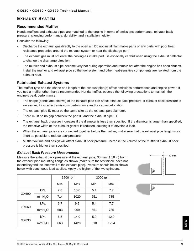
Exhaust Back Pressure MeasurementMeasure the exhaust back pressure at the exhaust pipe, 30 mm (1.18 in) from the exhaust pipe mounting flange as shown (make sure the test nipple does not extend beyond the inner wall of the exhaust pipe). Pressure should be as shown below with continuous load applied. Apply the higher of the two cylinders.
3600 rpm 3000 rpm
Min. Max Min. Max
GX690kPa 7.0 10.0 5.4 7.7
mmH2O 714 1020 551 785
GX660kPa 6.7 9.5 5.4 7.7
mmH2O 683 969 551 785
GX630kPa 6.5 14.0 5.0 12.0
mmH2O 663 1428 510 1224
30 mm
NEW

GX630 • GX660 • GX690 Technical Manual
10 © 2010 American Honda Motor Co., Inc — All Rights Reserved
Rigid Engine Mount Muffler InstallationThe frame must be rigid to prevent cracking when the exhaust pipe and muffler are connected. The muffler should be installed securely with bolts and nuts.
The muffler should be supported at two points (or more) using special rubber mounts designed for muffler support applications.
Check to see muffler vibration does not increase at any given engine speed, causing an abnormal increase in resonance.
Rubber Engine Mount Muffler InstallationA flexible pipe should be used between the muffler and exhaust pipe when the engine is mounted to the engine bed with rubber mounts. The flexible pipe ID must be the same as the exhaust pipe OD or larger.
The muffler should be supported at two points (or more) and should be installed securely with bolts and nuts to prevent muffler cracking from vibration during starting and stopping.
Check to see muffler vibration does not increase at any given engine speed, causing an abnormal increase in resonance.
ENGINE MOUNTING
Use an engine bed or frame with enough rigidity to allow maximum durability of the engine and attachment installation.
The engine must not wobble on the engine bed. Use an engine bed or frame that provides a flat surface for the engine to be mounted on. If there is a gap between the engine and the engine bed, the engine-mounting surface may be damaged.
InclinationHorizontal mounting and operation of the engine is recommended. If the engine must be operated on a slope, the incline position of the engine must not exceed 20° in any direction.
Resonance CheckThere must be no resonance when the engine and attachment are operated within the designated speed range. Slowly raise the engine speed from idle to maximum and check for resonance at any engine speed.
General Methods for Preventing ResonanceWhen engine accessories or a part of the attachment is resonating, increase the rigidity of the resonating part to bring the resonance point higher than the working engine speed range.
· Increase the rigidity of the engine bed and frame to bring the resonance point higher than the working engine speed range.
· Install the muffler on the engine body, using a rigid stay to prevent resonance of the muffler when the engine speed is within the specific operating speed range.

GX630 • GX660 • GX690 Technical Manual
© 2010 American Honda Motor Co., Inc — All Rights Reserved 11
Engine Acceleration/VibrationUsing a vibration meter, measure the vibration amplitude on three axes (vertical, lateral, and horizontal).
Direction Allowable G value
(Peak) (RMS)
Vertical 5 (49 m/s2) 3.5 (34 m/s2)
Horizontal 5 (49 m/s2) 3.5 (34 m/s2)
lateral 5 (49 m/s2) 3.5 (34 m/s2)HORIZONTAL
VERTICAL
LATERAL
GX630 • GX660 • GX690 Technical Manual
12 © 2010 American Honda Motor Co., Inc — All Rights Reserved
ELECTRICAL SYSTEM
Battery Use a 12 V battery with a minimum capacity of 45 AH (400 CCA).
FuseRecommended fuse size:
Battery CablesSelect battery cables to avoid greater than 0.5 volt drop in the cable during starter motor operation.
Battery cable size and length: (Gauge x Length)
Positive cable: AWG No. 4 x 1.5 m (5.0 ft.) maximumNegative cable: AWG No. 4 x 2.3 m (7.5 ft.) maximum
Types with Oil Alert: Attach the negative battery cable from the battery directly to the outer mounting bolt of the electric starter.
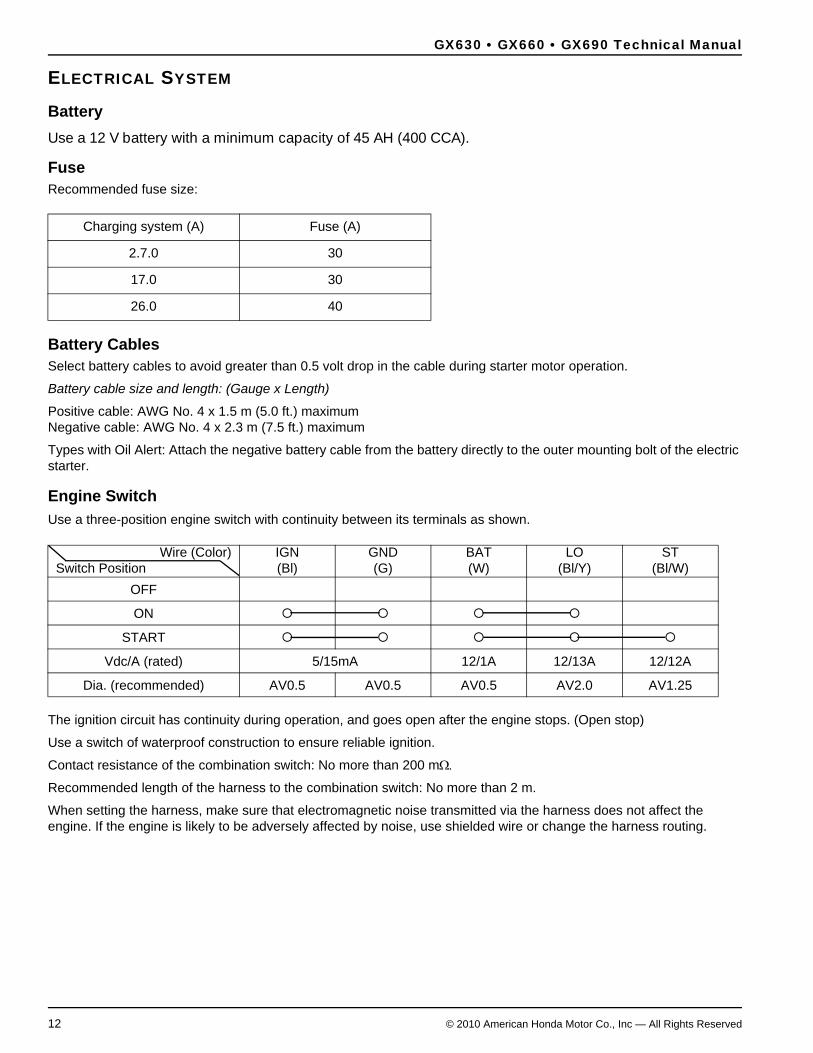
Engine SwitchUse a three-position engine switch with continuity between its terminals as shown.
The ignition circuit has continuity during operation, and goes open after the engine stops. (Open stop)
Use a switch of waterproof construction to ensure reliable ignition.
Contact resistance of the combination switch: No more than 200 mΩ.
Recommended length of the harness to the combination switch: No more than 2 m.
When setting the harness, make sure that electromagnetic noise transmitted via the harness does not affect the engine. If the engine is likely to be adversely affected by noise, use shielded wire or change the harness routing.
Charging system (A) Fuse (A)
2.7.0 30
17.0 30
26.0 40
Wire (Color) IGN(Bl)
GND(G)
BAT(W)
LO(Bl/Y)
ST(Bl/W)Switch Position
OFF
ON
START
Vdc/A (rated) 5/15mA 12/1A 12/13A 12/12A
Dia. (recommended) AV0.5 AV0.5 AV0.5 AV2.0 AV1.25
GX630 • GX660 • GX690 Technical Manual
© 2010 American Honda Motor Co., Inc — All Rights Reserved 13
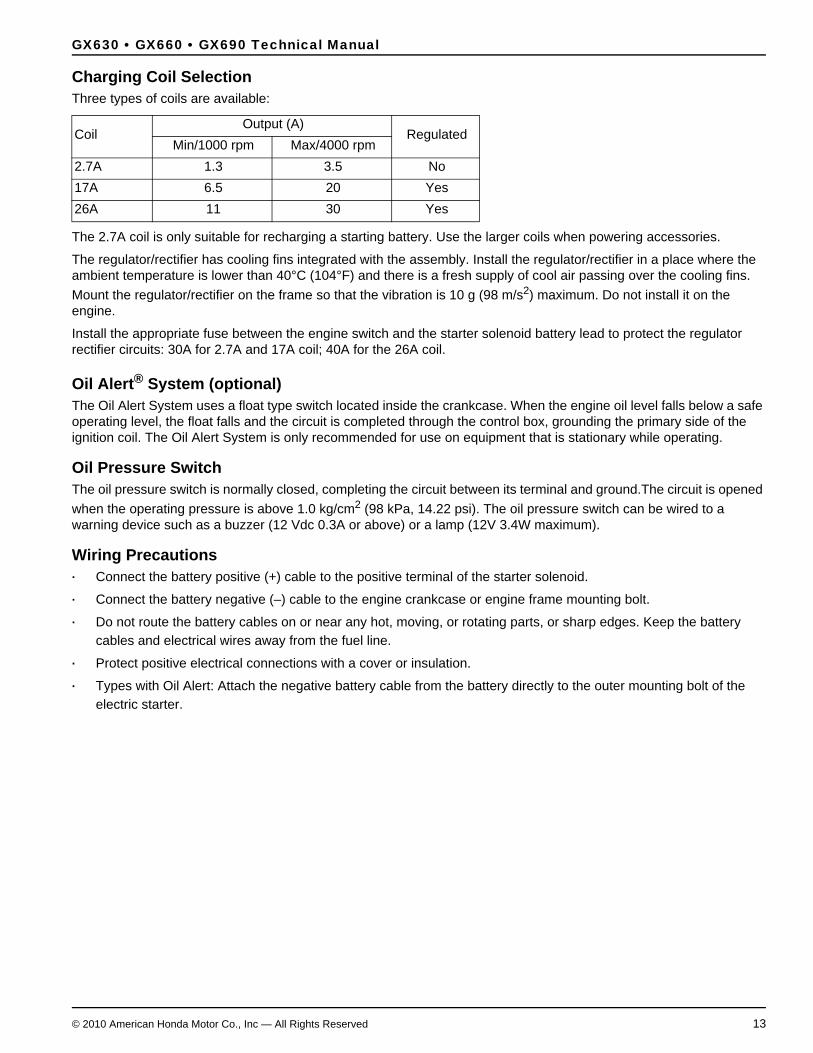
Charging Coil SelectionThree types of coils are available:
The 2.7A coil is only suitable for recharging a starting battery. Use the larger coils when powering accessories.
The regulator/rectifier has cooling fins integrated with the assembly. Install the regulator/rectifier in a place where the ambient temperature is lower than 40°C (104°F) and there is a fresh supply of cool air passing over the cooling fins. Mount the regulator/rectifier on the frame so that the vibration is 10 g (98 m/s2) maximum. Do not install it on the engine.
Install the appropriate fuse between the engine switch and the starter solenoid battery lead to protect the regulator rectifier circuits: 30A for 2.7A and 17A coil; 40A for the 26A coil.
Oil Alert® System (optional)The Oil Alert System uses a float type switch located inside the crankcase. When the engine oil level falls below a safe operating level, the float falls and the circuit is completed through the control box, grounding the primary side of the ignition coil. The Oil Alert System is only recommended for use on equipment that is stationary while operating.
Oil Pressure SwitchThe oil pressure switch is normally closed, completing the circuit between its terminal and ground.The circuit is opened when the operating pressure is above 1.0 kg/cm2 (98 kPa, 14.22 psi). The oil pressure switch can be wired to a warning device such as a buzzer (12 Vdc 0.3A or above) or a lamp (12V 3.4W maximum).
Wiring Precautions· Connect the battery positive (+) cable to the positive terminal of the starter solenoid.
· Connect the battery negative (–) cable to the engine crankcase or engine frame mounting bolt.
· Do not route the battery cables on or near any hot, moving, or rotating parts, or sharp edges. Keep the battery cables and electrical wires away from the fuel line.
· Protect positive electrical connections with a cover or insulation.
· Types with Oil Alert: Attach the negative battery cable from the battery directly to the outer mounting bolt of the electric starter.
CoilOutput (A)
RegulatedMin/1000 rpm Max/4000 rpm
2.7A 1.3 3.5 No17A 6.5 20 Yes26A 11 30 Yes

GX630 • GX660 • GX690 Technical Manual
14 © 2010 American Honda Motor Co., Inc — All Rights Reserved
WIRING DIAGRAMS
2.7A Charging systems - Remote Control Type
Control Box Type
BlackYellowBlueGreenRedWhite Gray
PinkLight greenLight blueOrangeBrown
WRGBuYBl
GrP
LgLbOBr
Y
Gr
Bl
W
Bl
(Gr)
(Bl)
W
(Gr)
(Bl)
BA
T
ST
LO
GN
D
IGN
W
Bl/Y
Bl/W W G B
l
Y Bl
Y Bl
(Bl)
(Bl/Y)
(Bl)
(Bl/Y)
Bl
Gr
Bl/Y
(W)
(Bl/W
)
W W
G
OFF
ON
IGN GND
ST
BAT LO ST
CHARGE COIL(2.7 A)
REGULATOR/RECTIFIER
FUSE (30 A)
COMBINATION SWITCH
STARTER MOTOR
BATTERYFUEL CUT No. 1 IGNITION
SPARK PLUG
OILLEVEL SOLENOID
COILSWITCH
No. 2IGNITION
SPARK PLUG
COIL
COMBINATION SWITCH
BlackYellowBlueGreenRedWhite Gray
PinkLight greenLight blueOrangeBrown
WRGBuYBl
GrP
LgLbOBr
Y
(Gr)
(Bl)
W
(Gr)
(Bl)B
AT
ST
LO
GN
D
IGN
W
Bl/Y
Bl/W W G B
l
Y Bl
Bu
Y Bl
(Bl)
(Y)
(Bu)
(Bl/Y)
(Bl)
(Y)
(Bu)
(Bl/Y)
Bl
Gr
Bu Y
Bl/Y G
Bu Y
Bl/Y G
Bl/Y
(W)
(Bl/W
)
W W
G
OFF
ON
IGN GND
ST
BAT LO ST
Gr
Bl
W
Bl
CHARGE COIL(2.7 A)
REGULATOR/RECTIFIER
FUSE (30 A)
COMBINATION SWITCH
HOUR METER
STARTER MOTOR
BATTERYFUEL CUT No. 1 IGNITION
SPARK PLUG
OILLEVEL SOLENOID
COILSWITCH
No. 2IGNITION
SPARK PLUG
COIL
CONTROL BOX
COMBINATION SWITCH

GX630 • GX660 • GX690 Technical Manual
© 2010 American Honda Motor Co., Inc — All Rights Reserved 15
17A Charging Systems - Remote Control Type
Control Box Type
BlackYellowBlueGreenRedWhite Gray
PinkLight greenLight blueOrangeBrown
WRGBuYBl
GrP
LgLbOBr
Gr
Y
Gr
W/Bu
Bl/Y
W
Bl
Gr
Gr
W/Bu
Bl/Y
W
Bl
(Gr)
(Gr)
(Bl/Y) W
(Gr)
(Gr)
(Bl/Y)
BA
T
ST
LO
GN
D
IGN
W
Bl/Y
Bl/W W G B
l
Y Bl
Y Bl
(Bl)
(Bl/Y)
(Bl)
(Bl/Y)
Gr
Gr
Bl/Y
(W)
(Bl/W
)
W W
G
OFF
ON
IGN GND
ST
BAT LO ST
CHARGE COIL(17 A)
REGULATOR/RECTIFIER
FUSE (30 A)
COMBINATION SWITCH
STARTER MOTOR
BATTERYFUEL CUT No. 1 IGNITION
SPARK PLUG
OILLEVEL SOLENOID
COILSWITCH
No. 2IGNITION
SPARK PLUG
COIL
COMBINATION SWITCH
BlackYellowBlueGreenRedWhite Gray
PinkLight greenLight blueOrangeBrown
WRGBuYBl
GrP
LgLbOBr
Gr
Y
Gr
W/Bu
Bl/Y
W
Bl
Gr
Gr
W/Bu
Bl/Y
W
Bl
(Gr)
(Gr)
(Bl/Y) W
(Gr)
(Gr)
(Bl/Y)
BA
T
ST
LO
GN
D
IGN
W
Bl/Y
Bl/W W G B
l
Y Bl
Bu
Y Bl
(Bl)
(Y)
(Bu)
(Bl/Y)
(Bl)
(Y)
(Bu)
(Bl/Y)
Gr
Gr
Bu Y
Bl/Y G
Bu Y
Bl/Y G
Bl/Y
(W)
(Bl/W
)
W W
G
OFF
ON
IGN GND
ST
BAT LO ST
CHARGE COIL(17 A)
REGULATOR/RECTIFIER
FUSE (30 A)
COMBINATION SWITCH
HOUR METER
STARTER MOTOR
BATTERYFUEL CUT No. 1 IGNITION
SPARK PLUG
OILLEVEL SOLENOID
COILSWITCH
No. 2IGNITION
SPARK PLUG
COIL
CONTROL BOX
COMBINATION SWITCH
GX630 • GX660 • GX690 Technical Manual
16 © 2010 American Honda Motor Co., Inc — All Rights Reserved
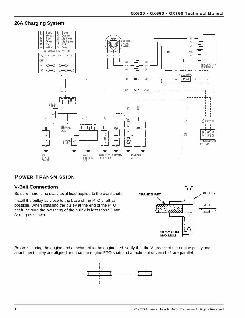
26A Charging System
POWER TRANSMISSION
V-Belt ConnectionsBe sure there is no static axial load applied to the crankshaft.
Install the pulley as close to the base of the PTO shaft as possible. When installing the pulley at the end of the PTO shaft, be sure the overhang of the pulley is less than 50 mm (2.0 in) as shown.
Before securing the engine and attachment to the engine bed, verify that the V-groove of the engine pulley and attachment pulley are aligned and that the engine PTO shaft and attachment driven shaft are parallel.
BlackYellowBlueGreenRedWhite Gray
PinkLight greenLight blueOrangeBrown
WRGBuYBl
GrP
LgLbOBr
Y
Gr
Gr
W/Bu
W
Bl
(Gr)
(Gr)
W
(Gr)
(Gr)
BA
T
ST
LO
GN
D
IGN
W
Bl/Y
Bl/W W G B
l
Y Bl
Y Bl
(Bl)
(Bl/Y)
(Bl)
(Bl/Y)
Gr
Gr
Bl/Y
(W)
(Bl/W
)
W W
G
OFF
ON
IGN GND
ST
BAT LO ST Gr
(Gr)(Gr)
Gr
CHARGE COIL(26 A)
REGULATOR/RECTIFIER
FUSE (40 A)
COMBINATION SWITCH
STARTER MOTOR
BATTERYFUEL CUT No. 1 IGNITION
SPARK PLUG
OILLEVEL SOLENOID
COILSWITCH
No. 2IGNITION
SPARK PLUG
COIL
COMBINATION SWITCH
Axial
Load =0
CRANKSHAFT
50 mm (2 in)MAXIMUM
PULLEY

GX630 • GX660 • GX690 Technical Manual
© 2010 American Honda Motor Co., Inc — All Rights Reserved 17
When installing a pulley on the PTO shaft, use a tapered pulley bushing for security. This is a very effective method in preventing the pulley from working loose when the inertia moment of the pulley and torque fluctuation is large.
The frame or engine bed must be rigid enough to prevent belt resonance in the working speed range of the engine. Size the pulleys so they do not cause resonance of the belt(s).
To reduce resonance, install a stay between the engine and attachment as shown below.
0 40 60 80 100 120
1000
2000
3000
4000
5000
6000
(N)
OTHER THAN UPWARD PULL RANGE
UPWARD PULL RANGE
1200
1000
800
600
400
200
0
(lbf)
DOWNWARDPULL RANGE
UPWARDPULLRANGE
ATTACHMENT
90°
ENGINE PTO
ENGINE BASE
Distance from engine side coverto center line of drive pulley
(mm)
STATIC RADIAL LOAD
20

GX630 • GX660 • GX690 Technical Manual
18 © 2010 American Honda Motor Co., Inc — All Rights Reserved
Front PTO Shaft Output• Power output from the flywheel PTO should not exceed 50% of the net power.
• Use a rubber coupling or similar material to prevent an impact load from being applied directly to the PTO.
• Pulley/belt usage:
• The pulley must be mounted away from the screen grid to provide adequate cooling (page 6).
• The pulley overhang must not exceed 150 mm (6 in).
• The belt load must be within the range of values shown in the graph below.
Starting PerformanceThe engine must be able to start with the attachment at the lowest recommended ambient temperature (-25°C, -13°F).
If the starting load of the attachment is too large when operating the starter motor, provide a clutch so you can separate the load from the engine when operating the starter.
Due to changes in oil viscosity, there will be an increased drag in attachments such as hydraulic pumps or gear cases as temperature drops. Start the engine with the ambient temperature at the lowest temperature recommended for operating the attachment. Verify that the attachment, as well as the engine, can start and operate normally.
Select the proper oil viscosity for the attachment according to the attachment’s working temperature.
Minimum engine cranking voltage 9.6 Vdc
Minimum engine cranking rpm 250 rpm
Maximum engine cranking amperage 200 A
Overhang amount (mm)
Allowable static axle load (N)

GX630 • GX660 • GX690 Technical Manual
© 2010 American Honda Motor Co., Inc — All Rights Reserved 19
INSTALLATION CONSIDERATIONS
Maintenance Points Accessibility When the engine is installed in an enclosure, provide an access panel or use an engine enclosure that can be opened and closed easily. See also Serviceability page 25.
The emission control information label on the engine must be visible when the engine is installed in the equipment. If it is not visible by removing a panel, lifting a hood, or other means not using tools, you must attach a supplemental label. See the Honda Emission Regulation Guide (TO971).
Left-front Side
Right-rear Side
AIR CLEANER
SPARK PLUG
FUEL FILTER
CONTROL PANEL
OIL FILTER
OIL DRAIN BOLT
PROTECTOR FANCOVER TYPE
OIL DRAIN BOLT
HIGH-MOUNT MUFFLER (B type)
SIDE-MOUNT MUFFLER
OIL FILLER CAP
SPARK PLUG
HIGH-MOUNT MUFFLER(A type)
ELECTRIC STARTER
OIL LEVEL DIPSTICK
OIL FILTER

GX630 • GX660 • GX690 Technical Manual
20 © 2010 American Honda Motor Co., Inc — All Rights Reserved
DIMENSIONAL DRAWINGSunit: mm (in)
(EXHAUSTPORT END)
67 (2.6)
405 (15.9)
135 (5.3)
133.
5 (5
.26)
207 (8.1)198.5 (7.81)
18°
50(2.0)
18°
50(2
.0)
M8x1.25 DEPTH 18287.3 (11.31)
(EXHAUST PORT CENTER)
154.
5 (6
.08)
287.
00 (1
1.34
)(E
XH
AU
ST
PO
RT
CE
NTE
R)
(2 PLACES)
(2 PLACES)M8x1.25 DEPTH 18
81(3.2)(EXHAUSTPORT END)
133.5(5.26)
438(17.2)
205(8.1)205(8.1)
245(9.6)
NEW

GX630 • GX660 • GX690 Technical Manual
© 2010 American Honda Motor Co., Inc — All Rights Reserved 21
Side Mount Mufflerunit: mm (in)
High Mount Muffler
238.5(9.39)
280(11.0)
307(12.1)
138.5
(5.4
5)
170.5
(6.7
1)
209(8.2)
166(6.5)
78(3.1)
275.8(10.86)
125.
5(4.
94)
205.
8(8.
10)
380(15.0)
68(2.7)
140
328
309.5
130.5
102.5

GX630 • GX660 • GX690 Technical Manual
22 © 2010 American Honda Motor Co., Inc — All Rights Reserved
Mounting and PTO Shaft Drawingsunit: mm (in)
Type Dimensions
Mount
B
103.
5 (4
.07)
18(0.7)
4 (0.2)
18 (0.2)
5/16-24UNF-2B TAP(4 PLACES)
3/8-16UNF-2B TAP(4 PLACES)7/16-14UNF-2B TAP
(4 PLACES)
125.
5 (4
.94)
30°30°
45° 45°
P.D.
127
P.D
.165
.1P.
D.1
96.9
Φ14
6.05
5 (0.2)
43.5 (1.71)
92 (3.6)
50 (2.0)
C1.
5
4.5 (0.18)
111.2 (4.38)
2 (0.1)
9.53 0+0.05
(0.375 ) 0+0.002
31
-0.1
3 0
(1.2
)
-0.0
05
0
0 -0.0
25
5/8
-18
UN
F2
B T
AP
Φ11
0 (
Φ4
.3)
Φ3
6.5
(Φ1
.4
)
Φ1
8.5
(Φ
0.7
3)
Φ1
6.5
(Φ
0.6
5)
0 -0.0
01
0
GX630 • GX660 • GX690 Technical Manual
© 2010 American Honda Motor Co., Inc — All Rights Reserved 23
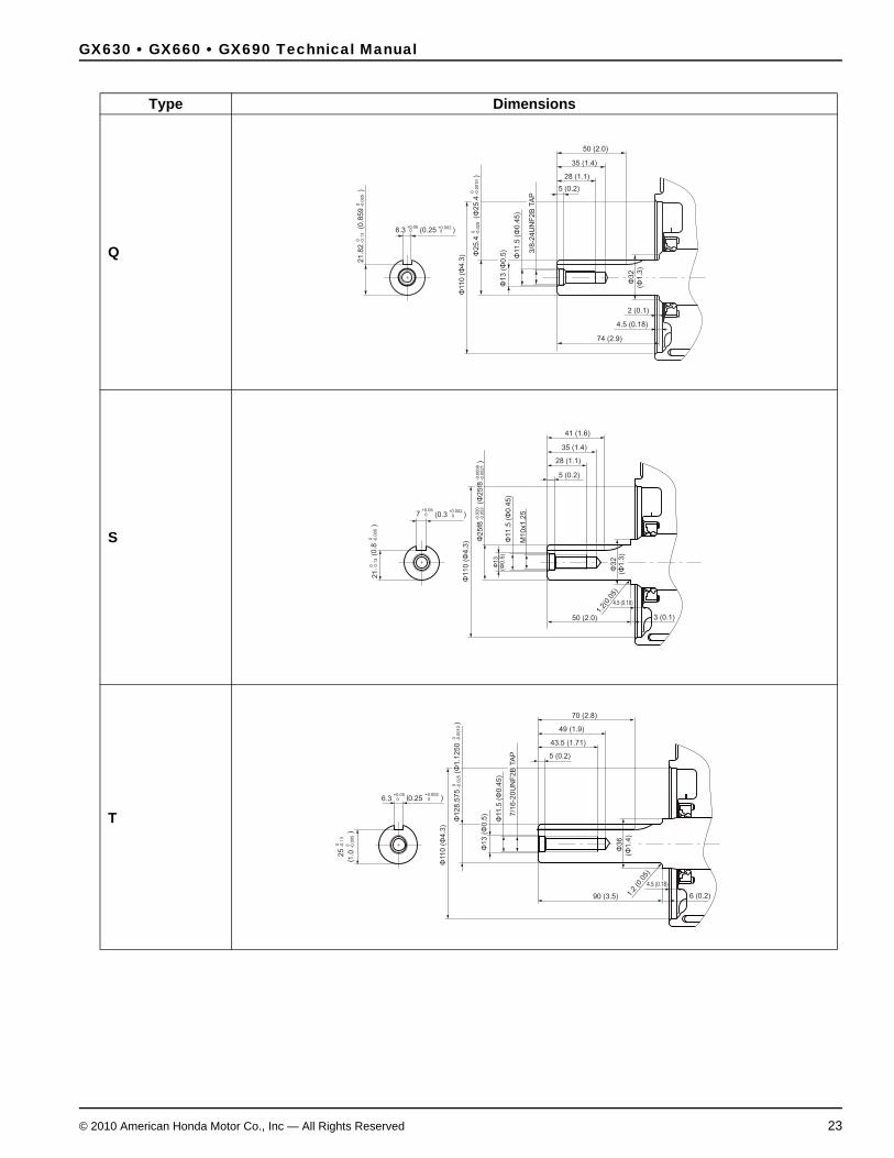
Type Dimensions
Q
S
T
5 (0.2)
28 (1.1)
50 (2.0)
35 (1.4)
4.5 (0.18)
74 (2.9)
2 (0.1)
6.3 0+0.05
(0.25 ) 0+0.002
21
.82
-0.1
3
0(0
.859 )
-0.0
05
0
0 -0.0
25
3/8
-24
UN
F2
B T
AP
Φ11
.5 (
Φ0
.45
)
Φ2
5.4
(Φ2
5.4
)
Φ1
3 (
Φ0
.5)
Φ11
0 (
Φ4
.3)
Φ3
2
(Φ1
.3)
0 -0.0
01
0
50 (2.0)
(0.3 )
3 (0.1)
1.2(
0.05
)
41 (1.6)
35 (1.4)
28 (1.1)
5 (0.2)-0
.05
3-0
.02
0
0+0.05
0+0.002
(0.8
)-0
.00
50
7
0-
0.1
32
1
M1
0x1
.25
4.5 (0.18)
Φ1
10
(Φ
4.3
)
Φ1
3(Φ
0.5
)Φ
11
.5 (
Φ0
.45
)
Φ2
5f8
(Φ2
5f8
)-0
.00
21
-0.0
00
8
Φ3
2(Φ
1.3
)
90 (3.5)
70 (2.8)
49 (1.9)
43.5 (1.71)
5 (0.2)
0+0.05
6.3
0 -0.1
32
5
7/1
6-2
0U
NF
2B
TA
P
0.25+0.002
0
1.0
-0.0
05
0
1.2
(0.0
5)
6 (0.2)
4.5 (0.18)
Φ11
0 (
Φ4
.3)
Φ1
3 (
Φ0
.5)
Φ1
28
.57
5(Φ
1.1
25
0
)
Φ11
.5 (
Φ0
.45
)
Φ3
6
(Φ1
.4)
-0.0
25
0-0
.00
10
0

GX630 • GX660 • GX690 Technical Manual
24 © 2010 American Honda Motor Co., Inc — All Rights Reserved
DIMENSIONS AND WEIGHTS
Type Dimensions
V
Model GX630R GX660R GX690ROverall length Q type: 405 mm (15.9 in)
V type: 426 mm (16.8 in)S type: 396 mm (15.6 in)T type: 429 mm (16.9 in)B type: 442 mm (17.4 in)
DEN type: 371 mm (14.6 in)Overall width 410 mm (16.1 in)Overall height 438 mm (17.2 in)Dry weight Q, S types: 44.4 kg (97.9 lbs)
V, T types: 44.6 kg (98.3 lbs)B type: 45.0 kg (99.2 lbs)
DEN type: 44.3 kg (97.7 lbs)Operating weight Q, S types: 46.0 kg (101.4 lbs)
V, T types: 46.2 kg (101.9 lbs)B type: 46.6 kg (102.7 lbs)
DEN type: 45.9 kg (101.2 lbs)Maximum angle of inclination Forward and backward: 20°
Left and right: 20°
4 (0.2)
25 (1.0)
84.3 (3.32)
77.5 (3.05)
(GAUGE LINE)
8.2 (0.32)
2 • 1/4TAPER PER F T.ON DIA.
32 (1.3)
0+0
.00
3
4.5 (0.18)
(TA
PE
R G
AU
GE
DIA
.)
5/1
6-2
4U
NF
2B
TA
P
Φ11
0 (
Φ4
.3)
Φ1
0 (
Φ0
.4)
Φ8
.5 (
Φ0
.43
3)
Φ2
2(Φ
0.9
)
Φ3
5 (
Φ1
.4)
0+0
.00
01

GX630 • GX660 • GX690 Technical Manual
© 2010 American Honda Motor Co., Inc — All Rights Reserved 25
SPECIFICATIONS
* The power rating of the engine indicated in this document is the net power output tested on a production engine for the enginemodel and measured in accordance with SAE J1349 at 3,600 rpm (net power) and at 2,500 rpm (max net torque). Massproduction engines may vary from this value. Actual power output for the engine installed in the final machine will vary dependingon numerous factors, including the operating speed of the engine in application, environmental conditions, maintenance, andother variables.
SERVICEABILITYThe following Maintenance section is duplicated from the applicable owner’s manual and is accurate at the time of publication of this manual. It is provided for your reference in considering serviceability issues.
Model GX630R GX660R GX690RDescription code GCBEK GCBFK GCBGKType 4 stroke, overhead valve, 90° V–twin cylinderDisplacement 688.0 cm3 (41.97 cu–in)Bore x stroke 78.0 x 72.0 mm (3.07 x 2.83 in)Net power (SAE J1349)* 15.5 kW (20.8 HP) /
3,600 min-1 (rpm)16.0 kW (21.5 HP) / 3,600 min-1 (rpm)
16.5 kW (22.1 HP) / 3,600 min-1 (rpm)
Continuous rated power 12 kW (16.1 HP) / 3,600 min-1 (rpm)
12.5 kW (16.8 HP) / 3,600 min-1 (rpm)
13 kW (17.4 HP) / 3,600 min-1 (rpm)
Maximum net torque (SAE J1349)* 48.3 N·m(4.93 kgf·m, 35.6 lbf·ft)
/ 2,500 min-1 (rpm)
48.3 N·m(4.93 kgf·m, 35.6 lbf·ft)
/ 2,500 min-1 (rpm)
48.3 N·m(4.93 kgf·m, 35.6 lbf·ft)
/ 2,500 min-1 (rpm)Maximum rpm (at no load) 3,850 ± 150 min-1 (rpm)Compression ratio 9.3 ± 0.2Fuel consumption (at continuous rated power)
6.0 Liters (1.59 US gal, 1.32 Imp gal) / h
6.3 Liters (1.66 US gal, 1.39 Imp gal) / h
6.7 Liters (1.77 US gal, 1.47 Imp gal) / h
Ignition system C.D.I.(Capacitor Discharge Ignition) type magnetoIgnition timing B.T.D.C. 9° / 1,000 min-1 (rpm)Spark advancer type Electronic typeSpark advancer performance B.T.D.C. 9° – 23°Spark plug ZFR5F (NGK)Lubrication system Forced feedOil capacity Without oil filter replacement: 1.5 Liters (1.59 US qt, 1.32 Imp qt)
With oil filter replacement: 1.7 Liters (1.80 US qt, 1.50 Imp qt)Recommended oil SAE 10W-30 API service classification SJ or laterCooling system Forced airStarting system Starter motorStopping system Ignition circuit openCarburetor 2 barrel horizontal type, butterfly valveAir cleaner Dual typeGovernor Mechanical centrifugalBreather system Reed valve type, PCV (Positive Crankcase Ventilation) typeFuel used Unleaded gasoline with a pump octane rating 86 or higher
GX630 • GX660 • GX690 Technical Manual
26 © 2010 American Honda Motor Co., Inc — All Rights Reserved

GX630 • GX660 • GX690 Technical Manual
© 2010 American Honda Motor Co., Inc — All Rights Reserved 27

GX630 • GX660 • GX690 Technical Manual
28 © 2010 American Honda Motor Co., Inc — All Rights Reserved
AIR CLEANER
Inspection
Cleaning
OIL FILTER
Change
OIL FILTER
SEAL
FILTER MOUNTING BASE OIL FILTER SOCKET
AIR CLEANER COVER LATCH
AIR CLEANER CASE
PACKING
FOAM FILTERELEMENT
PAPER FILTERELEMENT
AIR CLEANERCOVER
WING NUT
AIR CHAMBER
Operating the engine without an air filter, or with a damaged air
filter, will allow dirt to enter the engine, causing rapid engine wear.
This type of damage is not covered by the Distributor’s Limited
Warranty.
Remove the air cleaner cover and inspect the filter elements.
Clean or replace dirty filter elements. Always replace damaged
filter elements.
Pull the air cleaner cover latch to the unlocked position, and
remove the cover.
Remove the paper filter element and foam filter element from
the air cleaner case.
Inspect both filter elements, and replace them if they are
damaged. Always replace the paper filter element at the
scheduled interval (see page ).
A dirty air cleaner will restrict air flow to the carburetor, reducing
engine performance. If you operate the engine in very dusty areas,
clean the air filter more often than specified in the MAINTENANCE
SCHEDULE (see page ).
Remove the wing nut from the paper filter element.
Drain the engine oil, and retighten the drain bolt securely.
Remove the oil filter, and drain the oil into a suitable container.
Dispose the used oil and filter in a manner compatible with the
environment.
Use an oil filter socket, rather than a strap wrench, to avoid
striking and damaging the oil pressure switch.
Clean the filter mounting base, and coat the seal of the new oil
filter with clean engine oil.
Use only a Honda Genuine oil filter or a filter of equivalent
quality specified for your model. Using the wrong filter, or a
non-Honda filter which is not of equivalent quality, may cause
engine damage.
Oil filter tightening torque:
Refill the crankcase with the specified amount of the
recommended oil (see page ). Reinstall the oil filler cap and oil
level dipstick.
Start the engine, and check for leaks.
Stop the engine, and check the oil level as described on page .
If necessary, add oil to bring the oil level to the upper limit mark
on the oil level dipstick.
Screw on the new oil filter by hand until the seal contacts the
filter mounting base, then use an oil filter socket tool to tighten
the filter an additional 3/4 turn.
12 N·m (1.2 kgf·m , 9 lbf·ft)
Remove the foam filter element from the paper filter element.
1.
2.
3.
4.
5.
7
7
8
8
1.
2.
3.
4.
5.
6.
7.

GX630 • GX660 • GX690 Technical Manual
© 2010 American Honda Motor Co., Inc — All Rights Reserved 29

GX630 • GX660 • GX690 Technical Manual
30 © 2010 American Honda Motor Co., Inc — All Rights Reserved
Spark Arrester Cleaning & Inspection
SPARK ARRESTER (applicable types)
MUFFLER
SPARK ARRESTER
HIGH-MOUNT MUFFLER TYPE SIDE-MOUNT MUFFLER TYPE
SPARK ARRESTER SCREEN
SPECIALSCREW
SPARK ARRESTER
6 mm FLANGE BOLTS (4)
SPECIAL SCREWS (3)
MUFFLER PROTECTOR
MUFFLER
HIGH-MOUNT MUFFLER TYPE: Remove the special screw from
the muffler and remove the spark arrester.
Remove the spark arrester:
If the engine has been running, the muffler will be hot. Allow it to
cool before servicing the spark arrester.
The spark arrester must be serviced every 100 hours to keep it
functioning as designed.
Your engine is not factory-equipped with a spark arrester. The
spark arrester is optional part. In some areas, it is illegal to operate
an engine without a spark arrester. Check local laws and
regulations. A spark arrester is available from authorized Honda
servicing dealers.
Install the spark arrester and muffler protector in the reverse
order of disassembly.
The spark arrester must be free of breaks and holes. Replace the
spark arrester if it is damaged.
Use a brush to remove carbon deposits from the spark arrester
screen. Be careful to avoid damaging the screen.
SIDE-MOUNT MUFFLER TYPE: Remove the 6 mm flange bolts
from the muffler protector and remove the muffler protector.
Remove the special screws from the spark arrester and remove
the spark arrester from the muffler.
1.
2.
3.

GX630 • GX660 • GX690 Technical Manual
© 2010 American Honda Motor Co., Inc — All Rights Reserved 31
EVAPORATIVE EMISSIONS (CARB TIER 3)The OEM is responsible for meeting the CARB EVAP emissions regulations for products sold in California. This regulation concerns evaporative emissions from the fuel system. See the Emission Regulation Guide for additional details.
Shown below is a simplified overview of required components.
Additional information regarding manufacturers of CARB certified fuel system components can be found at: http://www.arb.ca.gov/msprog/offroad/sore/sorecomponent/sorecomponent.htm#.
CHARGE TUBE (BREATHER)The charge tube should be located as high as possible in the fuel tank. Fuel should not flow through the charge tube during regular use or during transportation
FUEL FILTER
CARBON CANISTERInstall the carbon canister so that the intake port will not be affected by the dynamic pressure of cooling air.
PURGE TUBEMaximum length: 80 cm.
PURGE JOINTConnect the purge tube to the joint on the dirty side of the air cleaner. Joint outer diameter: 11 mm
FUEL TUBEUse approved low permeation fuel tube between the filter and the fuel tank.
AIR OR EXHAUST GAS
FUEL VAPOR
FUEL VALVE
FUEL CAP (SEALED)(must be tethered and have positive feedback mechanism for closure.)

GX630 • GX660 • GX690 Technical Manual
32 © 2010 American Honda Motor Co., Inc — All Rights Reserved

