ptm rotary actuators and parallel grippers on 2d- and 3d ... · ptm rotary actuators and parallel...
TRANSCRIPT


PTM Rotary Actuators and Parallel Grippers
on 2D- and 3D- format
2 Product Catalog 06-2008
We are constantly working to improve our products. Therefore, we reserve the right for technical changes.
All dimensions in mm, general tolerances DIN 7168 medium.
For design engineering support we offer our complete product rangeon 2D- and 3D- format, on scale 1:1, metric dimensions.
Katalog 2008_E.qxp:Innenseiten KAT-D-2007 26.09.2008 10:38 Uhr Seite 2

Product Catalog 06-2008 3
Index
PTM Pneumatic Mini Actuators . . . . . . . . . . . . . . . . . . . . . . . . . . . . . . . . . . . . . . . DA . . . . . . . . . . . . . 4PTM Pneumatic Actuators . . . . . . . . . . . . . . . . . . . . . . . . . . . . . . . . . . . . . . . . . . . DA . . . . . . . . . . . . . 8PTM Pneumatic Rotary Modules . . . . . . . . . . . . . . . . . . . . . . . . . . . . . . . . . . . . . . . DM . . . . . . . . . . . . 10Shaft – Hub Connection for DA, Hub flange for HPA . . . . . . . . . . . . . . . . . . . . . . . . ZAF . . . . . . . . . . . . 12PTM Three Position Torque Cylinders . . . . . . . . . . . . . . . . . . . . . . . . . . . . . . . . . . DAD . . . . . . . . . . . 13PTM Hydraulic-Pneumatic Rotary Actuators . . . . . . . . . . . . . . . . . . . . . . . . . . . . . HPA . . . . . . . . . . . . 16PTM Hydraulic-Pneumatic Multi Position Cylinder, Rotary Switching Drive . . . . . HPAD . . . . . . . . . . 20
PTM Pneumatic Parallel Grippers . . . . . . . . . . . . . . . . . . . . . . . . . . . . . . . . . . . . . . PSM . . . . . . . . . . . 22PTM Pneumatic Parallel Grippers with u-shaped Jaws . . . . . . . . . . . . . . . . . . . . . PSMU . . . . . . . . . . 28PTM-Three-Pivot-Finger Gripper . . . . . . . . . . . . . . . . . . . . . . . . . . . . . . . . . . . . . . . DSG . . . . . . . . . . . 32PTM Parallel Tilting Grippers . . . . . . . . . . . . . . . . . . . . . . . . . . . . . . . . . . . . . . . . . . PSZ . . . . . . . . . . . . 34Several Positions Cylinders, Mounting Hole for Ejector . . . . . . . . . . . . . . . . . . . . . ZMZ . . . . . . . . . . . 42Spring Force, Attachement for Centering . . . . . . . . . . . . . . . . . . . . . . . . . . . . . . . . ZFS . . . . . . . . . . . . 43PTM End Position Switches as replacement parts . . . . . . . . . . . . . . . . . . . . . . . . . . . . . . . . . . . . . . . . . 44
Informations about LM, SM, DSK . . . . . . . . . . . . . . . . . . . . . . . . . . . . . . . . . . . . . . . . . . . . . . . . . . . . . . 45PTM Linear-Modules . . . . . . . . . . . . . . . . . . . . . . . . . . . . . . . . . . . . . . . . . . . . . . . . LM . . . . . . . . . . . . . 46PTM Tilting Modules . . . . . . . . . . . . . . . . . . . . . . . . . . . . . . . . . . . . . . . . . . . . . . . . . SM . . . . . . . . . . . . 48PTM Double Tilting Heads . . . . . . . . . . . . . . . . . . . . . . . . . . . . . . . . . . . . . . . . . . . . DSK . . . . . . . . . . . . 49
PTM Swivel Distributor, Power Distribution . . . . . . . . . . . . . . . . . . . . . . . . . . . . . . SLE 1014 . . . . . . . 52PTM Formulas . . . . . . . . . . . . . . . . . . . . . . . . . . . . . . . . . . . . . . . . . . . . . . . . . . . . . . . . . . . . . . . . . . . . . . 54General Terms an Conditions of Business . . . . . . . . . . . . . . . . . . . . . . . . . . . . . . . . . . . . . . . . . . . . . . . . 55
page
P M
Katalog 2008_E.qxp:Innenseiten KAT-D-2007 26.09.2008 10:38 Uhr Seite 3

Pneumatic Actuators
DA 0020, DA 0050, DA 0200, DA 0500DA 1500, DA 3000, DA 6000
4 Product Catalog 06-2008
All PTM-actuators are based on the rack-and pinion principle, picture 2.
This fact is responsible for small dimensions.For different mounting alternatives all PTM-actuators can be mounted on three or fourmounting surfaces.
Rotation angles more than 185° are available.
Our progressive working end positiondamping starts working just about 10°before reaching the end position bythrottling the exhaust air automatically. Thisguarantees reaching the exact end position.This excludes bouncing in the end positioneven during air pressure variation.
A technically necessary backlash of 0,5° isunvoidable at Mini-Actuators with rack-andpinion principle.
Main characteristics of our actuators aresmall dimensions, low weight and longlifetime. The power transmission is placed in the centerline of the rack piston toguarantee a very long lifetime. There arePTM-actuators which were returned forrepair only after 13 years of continuousrunning.
The smallest Pneumatic Mini Actuator DA0020 with rotation angle of 95° and a torqueof 20 Ncm, has the dimensions of only20x20x43 mm and a weight of 0,050 kg.These small dimensions and weights allowyou to increase the performance-weightratio of your robot or other applications.
picture 2
Katalog 2008_E.qxp:Innenseiten KAT-D-2007 26.09.2008 10:38 Uhr Seite 4

Brief technical data
Product Catalog 06-2008 5
P M
Material:– aluminum hard or black anodized– steel parts of stainless material or corrosion resistant– short time gas nitration
Operation / mounting position: – any position desired
Operating temperature: – -10° to +80° C (14° to 176° F)
Operating media:– filtered oiled or filtered oil-free air– Attention: Only oil-free air should be used at low rotation speed
to guarantee smooth movement.
Maintenance: – all PTM Pneumatic Actuators are maintenance-free.
Operating pressure: – maximum 8 bar = 118 psi (specs are based on 6 bar = 88 psi)
Rotation angle:– rotation angle max. 365°, 185° and 95°– adjustable until -20° in total by adjustment screws
Shaft-hub connection:
– if possible use keyway/key, if not use Loctite 601 for mounting of smallermasses on the shaft
– combination of clamping with set screw and Loctite 601(avoid under all circumstances boring the shaft)
– shrink or press fit h6/P5 or R6– clamping unit „Rfn 8006“ from Ringfeder Corporation
End position control with LED: – please consult our sheet „end position control“ on page 44
End position damping:– progressive damping characteristics,
the angle remains adjustable
End position: – the technically necessary backlash (until model DA 0500) must be elimina-
ted by external stops when highly accurate end positions are required.This is also possible with an external stop on a second shaft.
Installation recommendation:– to ensure long life of our devices the use of throttle valves is highly
recommended.
Katalog 2008_E.qxp:Innenseiten KAT-D-2007 26.09.2008 10:38 Uhr Seite 5

Pneumatic Mini Actuator
DA 0020, DA 0050, DA 0200, DA 0500
6 Product Catalog 06-2008
a, b, c mounting surface for model DA 0020, DA 0050, and DA 0200
a, b, c, d mounting surface for model DA 0500
e 4 threaded holes per head plate for air connection andmounting alternatives
f 4 threaded holes for model DA 0020, DA 0050 and DA0200 on side a and b for mounting alternatives
4 threaded holes for model DA 0500 on side a, b, c, dfor mounting alternatives
h adjustment screw to limit the rotation angle (model with end position damping under cover screw)
i centre bore
j connection cable for end position control
* model with or without end position damping
A model with end position control
B model with 2 shaft ends
C model with keyway/key
Attention: Leave 0,4 mm (0.0157 in)for assembly insert, included in thescope of delivery
end position control
mid of keyway=rotation angle
2
Katalog 2008_E.qxp:Innenseiten KAT-D-2007 26.09.2008 10:39 Uhr Seite 6

Product Catalog 06-2008 7
P MDA 0020-095 0020-185 0020-365 0050-095 0050-185 0050-365
rotation angle 95° 185° 365° 95° 185° 365°ø d1 4 h6 4 h6 4 h6 6 h6 6 h6 6 h6ø d2 7 J7x0,5 7 J7x0,5 7 J7x0,5 10 J7x0,5 10 J7x0,5 10 J7x0,5d3 M5x4 M5x4 M5x4 M5x4,5 M5x4,5 M5x4,5d4 M3x4 M3x4 M3x4 M3x5 M3x5 M3x5d5 M3x5,5 M3x5,5 M3x5,5 M3x5,5 M3x5,5 M3x5,5L1 20 20 20 25 25 25
L2 withoutend position damping
43,3 +0,4 -0,6 52,8 +0,4 -0,6 67,4 +0,4 -0,6 55,2 +0,4 -0,6 67,2 +0,4 -0,6 92,2 +0,4 -0,6
L2 withend position damping
58,1 +0,4 -0,6 67,6 +0,4 -0,6 82,2 +0,4 -0,6 70,0 +0,4 -0,6 82,0 +0,4 -0,6 107,0 +0,4 -0,6
L3 withoutend position damping
35,3 +0,2 -0,4 44,8 +0,2 -0,4 59,4 +0,2 -0,4 47,2 +0,2 -0,4 59,2 +0,2 -0,4 84,2 +0,2 -0,4
L3 withend position damping
47,3 +0,4 -0,2 56,8 +0,4 -0,2 71,4 +0,4 -0,2 59,2 ±0,4 71,2 ±0,4 96,2 ±0,4
L4 withoutend position damping
— — — — — —
L4 withend position damping
63,7 +0,6 -0,8 73,2 +0,6 -0,8 87,8 +0,6 -0,8 75,6 +0,6 -0,8 87,6 +0,6 -0,8 112,6 +0,6 -0,8
L5 withoutend position damping
— — — — — —
L5 withend position damping
2,8 2,8 2,8 2,8 2,8 2,8
L6 10 10 10 9 9 9L7 7,5 7,5 7,5 8,5 8,5 8,5L8 2 2 2 3 3 3L9 16 16 16 19 19 19L10 10 10 10 14 14 14A1 29,5 ±0,5 29,5 ±0,5 29,5 ±0,5 33 ±0,4 33 ±0,4 33 ±0,4B1 40 40 40 43 43 43C1 — — — 6,8 6,8 6,8C2 — — — 2 N9 2 N9 2 N9C3 — — — 6 6 6C4 — — — 2 2 2
FA axial N 20 20 20 55 55 55
CO radial N 90 90 90 220 220 220weight in kg 0,050 0,060 0,075 0,10 0,12 0,15
compressed air/stroke in cm3 0,7 1,4 2,8 1,6 3,2 6,4
DA 0200-095 0200-185 0200-365 0500-095 0500-185 0500-365rotation angle 95° 185° 365° 95° 185° 365°
ø d1 8 h6 8 h6 8 h6 10 h6 10 h6 10 h6ø d2 16 J7x0,5 16 J7x0,5 16 J7x0,5 26 J7x0,8 26 J7x0,8 26 J7x0,8d3 M5x5,5 M5x5,5 M5x5,5 R1/8x8 R1/8x8 R1/8x8d4 M3x7 M3x7 M3x7 M5x11 M5x11 M5x11d5 M4x9 M4x9 M4x9 M5x10 M5x10 M5x10L1 35 35 35 50 50 50
L2 withoutend position damping
70,2 +0,4 -0,6 89,2 +0,4 -0,6 127,2 +0,4 -0,6 120,2 +0,4 -0,6 153,2 +0,4 -0,6 219,2 +0,4 -0,6
L2 withend position damping
85,0 +0,4 -0,6 104,0 +0,4 -0,6 142,0 +0,4 -0,6 124,0 +0,4 -0,6 157,0 +0,4 -0,6 223,0 +0,4 -0,6
L3 withoutend position damping
62,2 +0,2 -0,4 81,2 +0,2 -0,4 119,2 +0,2 -0,4 103,2 +0,2 -0,4 136,2 +0,2 -0,4 202,2 +0,2 -0,4
L3 withend position damping
74,2 ±0,4 93,2 ±0,4 131,2 ±0,4 108,2 ±0,4 141,2 ±0,4 207,2 ±0,4
L4 withoutend position damping
— — — — — —
L4 withend position damping
90,6 +0,6 -0,8 109,6 +0,6 -0,8 147,6 +0,6 -0,8 129,6 +0,6 -0,8 162,6 +0,6 -0,8 228,6 +0,6 -0,8
L5 withoutend position damping
— — — — — —
L5 with end position damping
2,8 2,8 2,8 2,8 2,8 2,8
L6 15 15 15 20 20 20L7 11,5 11,5 11,5 17 17 17L8 3,5 3,5 3,5 7 7 7L9 28 28 28 36 36 36L10 15 15 15 32 32 32L11 — — — 45 45 45L12 — — — 38 38 38L13 — — — 6 6 6L14 — — — 11 11 11A1 43 ±0,4 43 ±0,4 43 ±0,4 58 ±0,4 58 ±0,4 58 ±0,4B1 65 65 65 89,8 89,8 89,8C1 8,8 8,8 8,8 11,2 11,2 11,2C2 2 N9 2 N9 2 N9 3 N9 3 N9 3 N9C3 8 8 8 12 12 12C4 5 5 5 6 6 6
FA axial N 180 180 180 470 470 470
CO radial N 770 770 770 1900 1900 1900weight in kg 0,25 0,33 0,4 0,8 1,0 1,3
compressed air/stroke in cm3 6,4 11,9 23,5 13,9 27,2 53,7
All dimensions in mm
Katalog 2008_E.qxp:Innenseiten KAT-D-2007 26.09.2008 10:39 Uhr Seite 7

Pneumatic Actuator
DA 1500, DA 3000, DA 6000
8 Product Catalog 06-2008
a, b, c mounting surfacee air connectionsf mounting alternatives on side a and bg mounting alternatives on side ch adjustment screw to limit the rotation anglesj connection cable for end position controlk centre borel centre bore
B model with 2 shaft ends
mid of keyway= rotation angle
end position control
shaft end 2 shaft end 1Clip
bearing
housing DA
Katalog 2008_E.qxp:Innenseiten KAT-D-2007 26.09.2008 10:39 Uhr Seite 8

Product Catalog 06-2008 9
P MDA 1500-095 1500-185 1500-365 3000-095 3000-185 3000-365 6000-095 6000-185 6000-365
rotationangle
95° 185° 365° 95° 185° 365° 95° 185° 365°
ø d1 15 h6 15 h6 15 h6 20 h6 20 h6 20 h6 25 h6 25 h6 25 h6ø d2 42 J7 42 J7 42 J7 47 J7 47 J7 47 J7 62 J7 62 J7 62 J7ø d3 28 J7 28 J7 28 J7 32 J7 32 J7 32 J7 47 J7 47 J7 47 J7d4 R1/8x9 R1/8x9 R1/8x9 R1/4x9 R1/4x9 R1/4x9 R1/4x9 R1/4x9 R1/4x9d5 M8x9 M8x9 M8x9 M8x9 M8x9 M8x9 M10x12 M10x12 M10x12d6 M6x10 M6x10 M6x10 M6x10 M6x10 M6x10 M8x13 M8x13 M8x13d7 M4x6 M4x6 M4x6 M6x10 M6x10 M6x10 M8x12 M8x12 M8x12L1 49 49 49 58,5 58,5 58,5 76 76 76L2 49 49 49 59 59 59 76 76 76L3 183,6 237 343,8 203,6 264,8 387,4 241 321 485L4 200 253,4 360,2 220 281,2 403,8 257,4 337,4 501,4L5 91,5 91,5 91,5 109,9 109,9 109,9 133 133 133L6 48,9 48,9 48,9 58,5 58,5 58,5 69 69 69L7 23 23 23 35 35 35 50 50 50L8 17 17 17 22,5 22,5 22,5 28 28 28L9 6 6 6 8 8 8 10 10 10L10 14 14 14 20 20 20 25 25 25L11 5 N9 5 N9 5 N9 6 N9 6 N9 6 N9 8 N9 8 N9 8 N9L12 40x40 40x40 40x40 50x50 50x50 50x50 60x60 60x60 60x60L13 7 7 7 6 6 6 8 8 8L14 12,5 12,5 12,5 12,5 12,5 12,5 12,5 12,5 12,5L15 12,5 12,5 12,5 10 10 10 13 13 13L16 24 24 24 39 39 39 50 50 50L17 72,5 72,5 72,5 72,5 72,5 72,5 100 100 100L18 8,5 8,5 8,5 9,5 9,5 9,5 13 13 13L19 32 32 32 40 40 40 50 50 50L20 27 27 27 31 31 31 38 38 38L21 1 1 1 1 1 1 2,15 2,15 2,15L22 3 3 3 3 3 3 5,1 5,1 5,1L23 1,2 1,2 1,2 1,7 1,7 1,7 2,2 2,2 2,2L24 2,6 2,6 2,6 3,1 3,1 3,1 4,2 4,2 4,2B1 92 92 92 116,5 116,5 116,5 161 161 161
ø B2 12 h6 12 h6 12 h6 15 h6 15 h6 15 h6 20 h6 20 h6 20 h6B3 13,5 13,5 13,5 17 17 17 22,5 22,5 22,5B4 5 5 5 6 6 6 8 8 8B5 12 12 12 14 14 14 20 20 20B6 4 N9 4 N9 4 N9 5 N9 5 N9 5 N9 6 N9 6 N9 6 N9
FA axial N 550 550 550 1000 1000 1000 5000 5000 5000
CO radial N 2200 2200 2200 6550 6550 6550 10000 10000 10000
weight in kg 1,56 1,9 2,2 2,7 3,2 4,5 4,6 5,5 7,2compressedair/stroke in
cm322,6 44,1 87,1 44,7 87,2 172,0 91,5 178,1 351,6
All dimensions in mm
Katalog 2008_E.qxp:Innenseiten KAT-D-2007 26.09.2008 10:39 Uhr Seite 9

Rotary Module
DM 0020, DM 0050, DM 0200, DM 0500
10 Product Catalog 06-2008
a mounting surface for additional turning equipmentb mounting surfacec mounting alternatived bores for mounting of additional equipmente 3 or 4 threaded holes for air connection
and mounting alternativesg connection cable for end position control
A model with end position controlB model with rotation angle 90°X model of actuator
stop for model withrotation angle 90°
rotation angle 180°
d* end position control
d* bore pattern only for DM 0020
stop for model withrotation angle 090°
rotation angle 090°
Katalog 2008_E.qxp:Innenseiten KAT-D-2007 26.09.2008 10:39 Uhr Seite 10

Product Catalog 06-2008 11
model DM 0020 DM 0050 DM 0200 DM 0200 DM 0500
suitable for: PSM 0030-007 PSM 0050-011 PSM 0200-013 PSM 0600-016 PSM 0600-016X DA 0020-185 DA 0050-185 DA 0200-185 DA 0200-185 DA 0500-185d1 M5x4 M5x4,5 M5x5,5 M5x5,5 R1/8x8
ø d2 3,4 3,4 3,4 4,4 4,5ø d3 6 6 6 8 8d4 M3x4 M3x5 M3x7 M3x7 M5x11L1 20 25 35 35 50L2 67,6 +0,4 -0,6 82 +0,4 -0,6 104 +0,4 -0,6 104 +0,4 -0,6 157 +0,4 -0,6L3 56,8 +0,4 -0,4 71,2 +0,4 -0,4 93,4 +0,4 -0,4 93,4 +0,4 -0,4 141,2 +0,4 -0,4L4 73,2 +0,6 -0,8 87,6 +0,6 -0,8 109,6 +0,6 -0,8 109,6 +0,6 -0,8 162,6 +0,6 -0,8L5 2,8 2,8 2,8 2,8 2,8L6 32 43 59 64,8 84,8L7 30 34 50 50 70L8 40 56 72 92 118L9 24 32 40 59 59L10 22 28 35 54 54L11 10 16,5 22 28 33L12 — 4,5 4,5 7,5 7,5L13 8 7,5 13 13,2 18,2L14 2,5 4 6 6 11L15 3 6 5,5 10,5 5L16 2 3 3,5 3,5 7L17 16 19 28 28 36L18 10 14 15 15 32L19 — 44 52 72 72L20 — — 10 15 15L21 4 2,2 3,2 3,2 3,2L22 10 12,5 17,5 17,5 22L23 — — — — 45L24 — — — — 6L25 — — — — 38L26 8,5 10,5 12 17 17L27 30 33 65 57 57L28 15 19 26 43 43L29 3 4,5 3,5 5,5 5,5A1 32,5 39 48,5 53,5 63B1 32,5 39 48,5 53,5 71
FA axial N 20 55 180 180 470
CO radial N 90 220 770 770 1900
weight in kg 0,08 0,19 0,5 0,6 1,3
P M
All dimensions in mm
Katalog 2008_E.qxp:Innenseiten KAT-D-2007 26.09.2008 10:39 Uhr Seite 11

Shaft-Hub Connection
with Cone Clamping
Hub flange for HPA 0750, HPA 1500, HPA 3000
Addition : Hub flange ZAF
12 Product Catalog 06-2008
Ordering Example: double cone clamping elements for actuator model DA 0200
for modelDA 0050(50 Ncm)
DAD 0050(50 Ncm)
DA 0200(200 Ncm)
DAD 0200(200 Ncm)
DA 0500(500 Ncm)
DAD 0500(500 Ncm)
ø d1 9 H7 9 H7 11 H7 11 H7 13 H7 13 H7ø d2 6 h6/H7 6 h6/H7 8 h6/H7 8 h6/H7 10 h6/H7 10 h6/H7ø d3 8 8 12 12 14 14L1 ca. 8 ca. 8 ca. 14 ca. 14 ca. 19 ca. 19L2 6 6 6 6 6 6L3 4 4 4 4 4 4L4 4,5 4,5 4,5 4,5 4,5 4,5L5 >/=0,1 >/=0,1 >/=0,1 >/=0,1 >/=0,1 >/=0,1L6 2 2 2 2 2 2L7 9,5 9,5 15,5 15,5 20,9 20,9L8 0,5 0,5 0,5 0,5 1,0 1,0L9 9,5 9,5 10,5 10,5 10,5 10,5
transmittable torquemounting examples
I / II2,25/3,4 Nm 2,25/3,4 Nm 4,8/7,4 Nm 4,8/7,4 Nm 9,9/15,3 Nm 9,9/15,3 Nm
clamping screw M3x8 DIN 912 M3x8 DIN 912 M4x12 DIN 912 M4x12 DIN 912 M5x12 DIN 912 M5x12 DIN 912clamping moment 2,5 Nm 2,5 Nm 4,0 Nm 4,0 Nm 8.5 Nm 8.5 Nm
ZAF 0750 1500 3000
for model HPA 0750 HPA 1500 HPA 3000
L27 11 13 16,1
L28 33,5 41 49,9
L29 22 25 30
L30 54 67 81,9
L31 25±0.01 34±0.01 37±0.01
ø d12 34 h6 43 h6 48 h6
ø d13 TK 50 69 74
ø d14 60-0.1 84-0.1 89-0.1
ø d15 6E7 8E7 8E7
ø d16 4xM6 4xM8 4xM8
All dimensions in mm
mounting example I : cone clamping element
mounting example II : double cone clamping elements
connection shown in an untightened condition * thread and head plate Loctite 932 and 221 respectively
driving hole d25
hub
DA housing
DA shaft
Katalog 2008_E.qxp:Innenseiten KAT-D-2007 26.09.2008 10:39 Uhr Seite 12

Three Position Torque Cylinder
Keyword : Mid position
Product Catalog 06-2008 13
Actuators with an exactly defined mid position (Attention: Backlash !) are based on three piston units. The twoexternal pistons push the piston with the rack into the mid position. If the two cylinders on both sides arewithout pressure and only the center piston is pressurized, the pinion will turn around the complete angle. Thespeciality of this construction is, that in spite of the small construction all pistons have end position damping.Field tests did prove, that this pneumatic end position damping is superior to the normally used miniature shockabsorbers.
Actuators with mid position are available with torque of 50 Ncm, 200 Ncm and 500 Ncm. The standard modelshave rotation angles of 180° or 90°. Other angles on request.
For other details please consult the data sheets for Three Position Torque Cylinder DAD 0050, DAD 0200 andDAD 0500.
P M
Katalog 2008_E.qxp:Innenseiten KAT-D-2007 26.09.2008 10:39 Uhr Seite 13

Three Position Torque Cylinder
DAD 0050, DAD 0200, DAD 0500
14 Product Catalog 06-2008
Attention: Leave 0,4 mm (0,0157 in) for assembly insert, included in the scope ofdelivery.
a, b, c mounting surface for model DAD 0050, DAD 0200
a, b, c, d mounting surface for model DAD 0500
e 4 threaded holes per head plate for air connection(mid position) and mounting alternatives
f 4 threaded holes for model DAD 0050 and DAD0200 on side a and b for mounting alternatives
f 4 threaded holes for model DAD 0500on side a, b, c, and d for mounting alternatives
h adjustment screw to limit the rotation angle(under cover screw)
i centre bore
j connection cable for end position control
k 2 threaded holes on side b, c, and d forair connection
A model with end position control
B model with 2 shaft ends
C model with keyway/key
schematic for DAD
rotation angleto the right
rotation angleto the left
mid position
end position control
= rotation angle
2= mid position
mid of keyway
Katalog 2008_E.qxp:Innenseiten KAT-D-2007 26.09.2008 10:39 Uhr Seite 14

Product Catalog 06-2008 15
Attention: end position control only possible in the end positions!
P Mmodel
DAD 0050-095
DAD 0050-185
DAD 0200-095
DAD 0200-185
DAD 0500-095
DAD 0500-185
rotation angle 95° 185° 95° 185° 95° 185°
ø d1 6 h6 6 h6 8 h6 8 h6 10 h6 10 h6
ø d2 10 J7 x0,5 10 J7 x0,5 16 J7 x0,5 16 J7 x0,5 26 J7 x0,8 26 J7 x0,8
d3 M5x4,5 M5x4,5 M5x5,5 M5x5,5 R1/8x8 R1/8x8
d4 M3x5 M3x5 M3x7 M3x7 M5x11 M5x11
d5 M3x5,5 M3x5,5 M4x9 M4x9 M5x10 M5x10
d6 M5x4 M5x4 M5x4 M5x4 R1/8x8 R1/8x8
L1 25 25 35 35 50 50
L2 105,9 ±0,5 117 ±0,5 137,5 ±0,5 156,6 ±0,5 191,6 ±0,5 225 ±0,5
L3 95,1 +0,5 -0,3 106,2 +0,5 -0,3 126,7 +0,5 -0,3 145,8 +0,5 -0,3 175,8 +0,5 -0,3 209,2 +0,5 -0,3
L4 111,5 ±0,7 122,6 ±0,7 143,1 ±0,7 162,2 ±0,7 197,2 ±0,7 230,6 ±0,7
L5 2,8 2,8 2,8 2,8 2,8 2,8
L6 9 9 15 15 20 20
L7 8,5 8,5 11,5 11,5 17 17
L8 3 3 3,5 3,5 7 7
L9 19 19 28 28 36 36
L10 14 14 15 15 32 32
L11 48,5 53,6 70,5 80,2 105,6 122,6
L12 4 4 4 4 7 7
L13 — — — — 6 6
L14 — — — — 11 11
L15 — — — — 45 45
L16 — — — — 38 38
A1 33 ±0,4 33 ±0,4 43 ±0,4 43 ±0,4 58 ±0,4 58 ±0,4
B1 43 43 65 65 89,8 89,8
C1 6,8 6,8 8,8 8,8 11,2 11,2
C2 2 N9 2 N9 2 N9 2 N9 3 N9 3 N9
C3 6 6 8 8 12 12
C4 2 2 5 5 6 6
FA axial N 55 55 180 180 470 470
CO radial N 220 220 770 770 1900 1900
weight in kg 0,2 0,3 0,6 0,7 1,2 1,3
All dimensions in mm
Katalog 2008_E.qxp:Innenseiten KAT-D-2007 26.09.2008 10:39 Uhr Seite 15

Hydraulic-Pneumatic Rotary Actuators
HPA 0750, HPA 1500, HPA 3000
16 Product Catalog 06-2008
The accelerated mass represents a major problem in pneumatics. The actuator mayselfdestruct because of the kinetic energy.Some clients had this unpleasant experiencealready. Throttle valves can be used to controlthe rotating speed. For damping of theaccelerated mass before reaching the endpositions it is possible to install hydraulicshockabsorbers. This will improve the situation,but the result is not totaly satisfactory.
We developped the Hydraulic-Pneumatic RotaryActuator -HPA to solve this problem. We splitthe task into two steps: The cheap, clean andcompressible medium air will continue to do the work for the actuation. But to control themoving mass the non compressible medium oil is used in a closed hydraulic system. This allowes to adjust the rotation speed exactly. A restart after an E-stop is possible without any problems. There are two independent andadjustable rotation speeds possible. This guarantees a precise and constant adjustmentof the end position damping.
Katalog 2008_E.qxp:Innenseiten KAT-D-2007 26.09.2008 10:39 Uhr Seite 16

Brief technical data
Product Catalog 06-2008 17
P M
Material:– aluminum hard or black anodized– steel parts of stainless material or corrosion resistant– shorttime gas nitration
Operating or mounting position: – any position desired
Operating media: – filtered oiled air or filtered oil-free air
Operating pressure: – maximum 8 bar = 118 psi (specs are based on 6 bar = 88 psi)
Rotation speed:– exactly adjustable stroke speeds are possible through a closed loop
hydraulic system– no extra pipes for leakage of hydraulics necessary
Rotation time:– from 0,5 sec. to several minutes at a rotation angle
of 180° for example
Rotation angle:– rotation angle of maximum 365°, 185° and 95°– adjustable until -15° through adjustment screws
End position damping:– progressive damping characteristics– the damping distance and damping characteristics are adjustable
End position control with LED: – please see our sheet "end position control" on page 44
Shaft-Hub connection:– keyway/key– hub flange
Operating temperature: – -10° C to +80° C (14°F to 176°F)
Maintenance: – all PTM actuators are maintenance-free
Installation information:– because of the hydraulic controlled movements the use of the
throttle valves is not necessary
Katalog 2008_E.qxp:Innenseiten KAT-D-2007 26.09.2008 10:39 Uhr Seite 17

Hydraulic-Pneumatic Rotary Actuators
HPA 0750, HPA 1500, HPA 3000
18 Product Catalog 06-2008
a, b, c mounting surface
e air connections, 2x
f mounting alternatives, 4x bores for mounting DIN74 with through holes on side a, b
g mounting alternatives, 4x threaded holes on side a, b, c
h adjustment screws to limit the rotation angle until -15°
j adjustment screw for rotation speed
k adjustment screws for end position damping
l connection cable for end position control
m centre bore
Attention: Dimensions and orderingcode for HPA-hub flange you willfind on page 12 of the catalog.
ADDITION : Hub flange ZAF
Attention: Dimensions of shaft end 2 areidentical with shaft end of the basic model.
end position control
Dimensions:Detail X
housingbearing
clip shaft end 2
d8 =
mou
ntin
g di
amet
er
shaft end 1
through hole at hollowshaft
mid of keyway =rotation angle
Katalog 2008_E.qxp:Innenseiten KAT-D-2007 26.09.2008 10:39 Uhr Seite 18

Product Catalog 06-2008 19
model HPA 0750 HPA 1500 HPA 3000
torque 750 Ncm at 6 bar 1500 Ncm at 6 bar 3000 Ncm at 6 bar
rotationangle
095° 185° 365° 095° 185° 365° 095° 185° 365°
L1 210,8 270,4 389,8 233,2 305,6 450,4 257,8 339,4 502,8L2 102,8 132,6 192,3 114,1 150,3 222,7 125,8 166,6 248,3L3 108,0 137,8 197,5 119,1 155,3 227,7 132,0 172,8 254,5L4 95,9 125,7 185,4 107,2 143,4 215,8 118,9 159,7 241,4L5 103,5 133,3 193,0 114,6 150,8 223,2 127,5 168,3 250,0L6 73,0 73,0 73,0 89,0 89,0 89,0 106,0 106,0 106,0L7 30,0 30,0 30,0 35,0 35,0 35,0 40,0 40,0 40,0L8 22,5 22,5 22,5 28,0 28,0 28,0 34,0 34,0 34,0L9 5,0 5,0 5,0 6,0 6,0 6,0 6,0 6,0 6,0L10 33,0 33,0 33,0 42,0 42,0 42,0 54,0 54,0 54,0L11 70,0 70,0 70,0 98,0 98,0 98,0 108,0 108,0 108,0L12 39,0 39,0 39,0 50,0 50,0 50,0 62,0 62,0 62,0L13 84,6 84,6 84,6 103,6 103,6 103,6 123,8 123,8 123,8L14 78,0 78,0 78,0 107,0 107,0 107,0 118,0 118,0 118,0
ø L15 76,0 76,0 76,0 107,0 107,0 107,0 118,0 118,0 118,0L16 88,0 88,0 88,0 120,0 120,0 120,0 130,0 130,0 130,0L17 60,0 60,0 60,0 86,0 86,0 86,0 92,0 92,0 92,0L18 25,0 25,0 25,0 28,0 28,0 28,0 36,0 36,0 36,0L19 3,0 3,0 3,0 4,0 4,0 4,0 4,0 4,0 4,0L20 6,0 N9 6,0 N9 6,0 N9 8,0 N9 8,0 N9 8,0 N9 8,0 N9 8,0 N9 8,0 N9L21 22,5 22,5 22,5 28,0 28,0 28,0 33,0 33,0 33,0L22 33,0 33,0 33,0 41,0 41,0 41,0 46,0 46,0 46,0L23 81,4 111,2 170,9 91,0 127,0 199,0 104,0 144,8 226,5L24 3,0 3,0 3,0 3,6 3,6 3,6 4,1 4,1 4,1L25 1,2 1,2 1,2 1,5 1,5 1,5 2,0 2,0 2,0L26 1,0 1,0 1,0 1,5 1,5 1,5 2,0 2,0 2,0L27 43,0 43,0 43,0 54,0 54,0 54,0 66,0 66,0 66,0
ø d1 20,0 h6 20,0 h6 20,0 h6 25,0 h6 25,0 h6 25,0 h6 30,0 h6 30,0 h6 30,0 h6ø d2 42,0 J7 42,0 J7 42,0 J7 52,0 J7 52,0 J7 52,0 J7 62,0 J7 62,0 J7 62,0 J7d3 4xM5/8 4xM5/8 4xM5/8 4xM6/14 4xM6/14 4xM6/14 4xM8/15 4xM8/15 4xM8/15d4 4xM5/8 4xM5/8 4xM5/8 4xM6/10 4xM6/10 4xM6/10 4xM8/15 4xM8/15 4xM8/15
ø d5 4x5,4 4x5,4 4x5,4 4x6,4 4x6,4 4x6,4 4x6,4 4x6,4 4x6,4ø d6 10x5,5 10x5,5 10x5,5 11x6,5 11x6,5 11x6,5 11x6,5 11x6,5 11x6,5d7 M6x12 M6x12 M6x12 M8x16 M8x16 M8x16 M10x18 M10x18 M10x18
ø d8 max. 30,0 30,0 30,0 40,0 40,0 40,0 50,0 50,0 50,0d9 R1/8x8 R1/8x8 R1/8x8 R1/8x8 R1/8x8 R1/8x8 R1/4x10 R1/4x10 R1/4x10
ø d10 36,0 36,0 36,0 44,0 44,0 44,0 52,0 52,0 52,0ø d11 max. 11,0 11,0 11,0 15,0 15,0 15,0 18,0 18,0 18,0
FA axial N 1250 1250 1250 1750 1750 1750 5000 5000 5000
CO radial N 5000 5000 5000 7000 7000 7000 10000 10000 10000
weight in kg ca. 2,5 ca. 2,6 ca. 2,9 ca. 3,4 ca. 3,9 ca. 4,4 ca. 5,8 ca. 6,4 ca. 6,9compressedair/stroke in
cm312,7 24,7 48,7 26,4 51,4 101,5 45,8 89,1 175,8
All dimensions in mm
P M
Katalog 2008_E.qxp:Innenseiten KAT-D-2007 26.09.2008 10:39 Uhr Seite 19

Hydraulic-Pneumatic Multi-Position Cylinder
HPAD 3000Rotary Switching Drive
20 Product Catalog 06-2008
Our well-proven Hydraulic-Pneumatic Rotary Actuator HPA 3000 is an outstanding, position-precise, multi-position drive, and a rotary switching drive, which works by means of an additional structure which accepts theblocking and interlocking functions of the drive shaft. The turntable does not lift during the pivoting andswitching operation, unlike traditional rotary indexing tables, therefore there is no change in the height position.
Special advantages are:
– The large torque in relation to weight and construction size.– The torque is 3000 Ncm.– The pivot angle steps are either 45 degrees or 90 degrees.– All step variants (forward or back-infinite) are possible.– The weight is only approx. 7,5 kg, and approx. 8,5 kg.– Position precision <0,01°– No lifting of the switching table.– The pivot speed is exactly adjustable.– The adjustable pivot times extend from min. 0,5 sec. to several minutes.– The end-position damping is progressive and adjustable.– The drive is maintenance free.– No functional disturbances through dirt accumulation, drive elements are encased.
ATTENTION:
– Before the pivoting of the turntable, the engaging jaw at the connection e2/P3-> LED 1 must have compressed air applied. Vent for interlocking.For the cycle forward-switching it is necessary to run the drive back beforehandwith vented engaging jaw e2/P3 -> LED 2 .
All advantages of our well known HPA design series, which have been well proven over a long time, have been takenover. (see catalog page 16-19)
Katalog 2008_E.qxp:Innenseiten KAT-D-2007 26.09.2008 10:39 Uhr Seite 20

Product Catalog 06-2008 21
a, b, c mounting surfacese1 air connections 2x for actuation (forward/back)e2 air connection 1x for engaging jaw (on/off)f threaded bores for mounting 4x9 mounting alternatives, 4x threaded bores
on mounting surfaces a, b, c
h adjustment screws to limit the rotation angle (fixed setting)
j adjustment screw for rotation speedk adjustment screws for end position dampingI connection cable for end position controlm centering shoulder
P M
LED 1 LED – signal engaging jaw ON,turntable unlocked, ready for pivoting
LED 2 LED – signal engaging jaw OFF,turntable locked
ATTENTION:Before the pivoting of the turntable, the engaging jaw at the connection e2/P3 must have compressed air applied. Vent for interlocking.
For the cycle forward-switching it is necessary to run the drive back beforehandwith vented engaging jaw e2/P3.
model HPAD 3000
torque 3000 Ncm at 6 barrotation angle 45°-steps 90°-steps 45°-steps 90°-steps
L1 247,6 257,8 d1 ø 30,0 h6 ø 30,0 h6L2 120,7 125,8 d2 ø 100,0 ø 100,0L3 126,9 132,0 d3 ø 107,0 ø 107,0L4 113,8 118,9 d6 ø 130,0 ø 130,0L5 122,4 127,5 d7 4x M8x17 4x M8x17L6 92,0 92,0 d8 4x M8x15 4x M8x15L7 98,9 104,0 d9 R1/4x10 R1/4x10L8 34,0 34,0 d10 ø 52,0 x 2,0 ø 52,0 x 2,0L9 6,0 6,0 d11 ø 118,0 ø 118,0L10 54,0 54,0 d12 ø 56,0 ø 56,0L11 108,0 108,0 d13 M5x5 M5x5L12 62,0 62,0L13 123,8 123,8 W1 45° 45°L14 118,0 118,0 W2 4x90° 4x90°L15 5,0 5,0L16 130,0 130,0L17 10,5 10,5L18 16,0 16,0L19 20,0 20,0L20 6,0 N9 6,0 N9L21 108,0 108,0L22 46,0 46,0L23 105,0 105,0 FA axial N 5000 5000L24 3,0 3,0 CO radial N 15000 15000L25 32,0 32,0 weight kg ca. 7,5 ca. 8,5L26 31,0 31,0L27 34,8 34,8L28 39,0 39,0L29 10,0 10,0L30 10,0 10,0 All dimensions in mm
actuator
end position control
Katalog 2008_E.qxp:Innenseiten KAT-D-2007 26.09.2008 10:39 Uhr Seite 21

Pneumatic Parallel Gripper
PSM, PSMU
22 Product Catalog 06-2008
PTM-Parallel Grippers are based on the rack-and-pinionprinciple like our rotating actuators. (picture 2) This factallows for a compact design with small dimensions and lowweight while still offering a high grip force.
The rack and pinion design produces an even clampingforce over the whole range. The clamping jaws areabsolutly centered in each position. Shortest clampingtimes are possible.
Each base jaw is connected tightly with one rack. Thiscreates the great advantage that the jaws are firmly guidedover the whole length of the gripper.
This long jaw guidance guarantees close tolerance, highprecission and long life.
It is possible to work with very long clamping fingerswithout any problems.
This advantages are enhanced in the alternative -PSMU-the PTM-Parallel Gripper with u-shaped jaws.
Another option is the use of a spring in our ParallelGrippers, model ZFS, to secure the grip force during airpressure failure. With this it is possible to work only withone air connection.
Our Multi Position Cylinders -ZMZ- offer as many as twoadditional stops or additional strokes, which is veryimportant in case of space restrictions.
The „Attachment for centering“ guarantees an exactexchange or a quick change position of the ParallelGripper.
picture 2
Katalog 2008_E.qxp:Innenseiten KAT-D-2007 26.09.2008 10:39 Uhr Seite 22

Brief technical data
Product Catalog 06-2008 23
P M
Material:– aluminum hard or black anodized– steel parts of stainless material or corrosion resistant– shorttime gas nitration
Operating or mounting position: – any position desired
Operating temperature: – -10° to +80° C (14° to 176° F)
Operating media:– filtered oiled air, or filtered oil-free air
– Attention: only oil-free air should be used at low movements asinterruptions could harm the smooth process.
Operating pressure: – maximum 6 bar (specs are based on 6 bar = 88 psi)
Maintenance: – all PSM units are maintenance-free
Base jaw guide:
– bronze bushings, self lubrication– each base jaw is connected tightly with one rack– therefore each jaw is guided over the whole length of the gripper– this guarantees high accuracy and long life
Clamping force: – constant over the whole stroke
Jaw stroke: – can be adjusted by both cylinder head plates, if necessary,
with adjustment screws
Ejection: – all PSM units are provided with an ejector pin with a spring, which
can be mounted in the pinion, if necessary
End position control with LED: – please see our sheet „end position control“ (Page 44)
Cover: – possible for all PSM units with the smallest stroke
Clamping components: – are generally manufactured by the customer for external or internal gripping
Installation of clamping comp:
– the connection between base jaw and clamping components isadjustable
– for this reason each base jaw has a fitted bore, two threaded holesand a keyway (view B-B)
Installation recommendation: – to ensure long life of our devices the use of throttle valves is highly
recommended
Katalog 2008_E.qxp:Innenseiten KAT-D-2007 26.09.2008 10:40 Uhr Seite 23

Parallel Gripper
PSM 0030, PSMU 0030
24 Product Catalog 06-2008
a mounting surface with 3 threaded holesb base jawc adjustment screw on each end for base
jaw stroked diam. 2 mm (0.079 in) for mounting of an
ejector pin (sheet „mounting bore forejector“)
e1 air connection „Opening“e2 air connection „Closing“f connection cable for end position control
A model with end position control
please consult table:1) loading of base jaw from direction „A“
permissible in N2) base jaw stroke in mm3) compressed air per stroke in cm3
4) clamping force at 6 bar (88 psi) on one side / centric gripping force in N
Z at base jaw closed
end position control
view B-B
u-shaped model
Katalog 2008_E.qxp:Innenseiten KAT-D-2007 26.09.2008 10:40 Uhr Seite 24

Product Catalog 06-2008 25
P Mmodel PSM 0030-007 PSM 0030-030 PSM 0030-052 PSMU 0030-007 PSMU 0030-030 PSMU 0030-052
ø d1 15 J7 15 J7 15 J7 15 J7 15 J7 15 J7
d2 M5x4,5 M5x4,5 M5x4,5 M5x4,5 M5x4,5 M5x4,5
d3 — — - — — -
d4 M3x4 M3x4 M3x4 M3x4 M3x4 M3x4
ø d5 4 J7 4 J7 4 J7 4 J7 4 J7 4 J7
d6 M3x6,5 M3x6,5 M3x6,5 M3x6,5 M3x6,5 M3x6,5
d7 M3x4 M3x4 M3x4 M3x4 M3x4 M3x4
ø d8 4 4 4 4 4 4
d9 — — — — — —
L1 40 63 98,5 40 63 98,5
max. L2 40 87 150,5 60,5 136,5 215
L3 31,3 31,3 31,3 35,8 35,8 35,8
L4 20,5 20,5 20,5 20,5 20,5 20,5
L5 17 17 17 17 17 17
L6 9 9 9 9 9 9
L9 8,5 8,5 8,5 8,5 8,5 8,5
L10 11,5 11,5 11,5 11,5 11,5 11,5
L11 10 10 10 26,5 38 49
L12 6,5 6,5 6,5 6,5 6,5 6,5
L13 0,3 0,3 0,3 — — —
L18 3 3 3 3 3 3
L19 15 15 15 15 15 15
L20 5 5 4,5 5 5 4,5
L21 30 53 89,9 30 53 89,9
L22 15,5 15,5 15,5 15,5 15,5 15,5
L23 — — — — — —
L24 6,2 6,2 11,9 6,2 6,2 11,9
L25 27,6 50,6 74,7 27,6 50,6 74,7
L26 4 4 4 4 4 4
L27 5 5 5 5 5 5
L28 — — — 60,5 106,5 163,5
L29 1,8 1,8 1,8 1,8 1,8 1,8
L30 2 F9 2 F9 2 F9 2 F9 2 F9 2 F9
L31 1 1 1 1 1 1
L32 1 1 — 1 1 —
L33 6 6 6 6 6 6
L34 23,8 23,8 23,8 23,8 23,8 23,8
L39 — — - 19,8 19,8 19,8
L40 19,5 19,5 19,5 19,5 19,5 19,5
A1 30 30 30 30 30 30
A2 18,4 18,4 18,4 18,4 18,4 18,4
A3 min. 3 8 20 3 8 20
1) 65 50 50 90 75 75
2) 2x3,5 2x15 2x26 2x3,5 2x15 2x26
3) 0,6 2,6 5,0 0,6 2,6 5,0
4) 60/30 60/30 60/30 60/30 60/30 60/30
weight in kg 0,065 0,09 0,12 0,09 0,13 0,17
Z 0,5 0,5 13,5 0,5 0,5 13,5
All dimensions in mm
Katalog 2008_E.qxp:Innenseiten KAT-D-2007 26.09.2008 10:40 Uhr Seite 25

Parallel Gripper
PSM 0050, PSM 0200, PSM 0600
26 Product Catalog 06-2008
a mounting surface with 2, 4, or 6 threaded holes
b base jaw
c adjustment screw on each end forbase jaw stroke limitation
d diam. 2 mm (0,079 in) for installation of anejector pin (sheet „mounting hole forejector)
e1 air connection „Opening“
e2 air connection „Closing“
f connection cable for end position control
A model with end position control
please consult table:
1) loading of base jaw from direction „A“ permissible in N
2) base jaw stroke in mm
3) compressed air per stroke in cm3
4) clamping force at 6 bar (88 psi) on oneside / centric gripping force in N
Z at base jaw closed
view B-Bturned by 90°
end position control
Katalog 2008_E.qxp:Innenseiten KAT-D-2007 26.09.2008 10:40 Uhr Seite 26

Product Catalog 06-2008 27
P MPSM 0050-011 0050-029 0050-052 0200-013 0200-027 0200-052 0200-105 0600-016 0600-030 0600-060
ø d1 18 J7 18 J7 18 J7 28 J7 28 J7 28 J7 28 J7 38 J7 38 J7 38 J7d2 M5x4,5 M5x4 M5x4 M5x4,5 M5x4,5 M5x4,5 M5x4,5 M5x5 M5x5 M5x5d3 M3x5,5 M3x5,5 M3x5,5 M3x5 M3x5 M3x5 M3x5 M4x8 M4x8 M4x8d4 M3x5,5 M3x4 M3x4 M3x5,5 M3x5 M3x5 M3x5 M4x8 M4x8 M4x8
ø d5 4 J7 4 J7 4 J7 4 J7 4 J7 4 J7 4 J7 5 J7 5 J7 5 J7d6 M3x5,5 M3x5,5 M3x5,5 M3x5,5 M3x5,5 M3x9,5 M3x9,5 M4x6 M4x6 M4x6d7 M3x4 M3x4 M3x4 M3x4 M3x4 M4x5,5 M4x5,5 M4x4 M4x4 M4x4
ø d8 6 6 6 6 6 8 8 10 10 10d9 — — — — M4x5,5 M4x7 M4x7 — — —d10 — — — M4x5 — — — M5x10 M5x10 M5x10
L1 56 75 135 72 86 138 219 92 106 156L2 max. 65,5 103 160 74,5 105,5 172 302,5 96 128 186
L3 39,8 39,8 39,8 49,8 49,8 54 54 66,5 66,5 66,5L4 31 31 31 37,5 37,5 37,5 37,5 59 59 59L5 27 27 27 30 30 30 30 44,2 44,2 44,2L6 13 13 13 13 13 15 15 26,1 26,1 26,1L7 3 3 3 3 3 3 3 5 5 5L8 9 9 9 9 9 9 9 15 15 15L9 11 11 11 16 16 16 16 24 21 24L10 17,5 17,5 17,5 19 19 19 19 35 35 35L11 15 15 20 18 18 18 18 23 23 23L12 9 9 10 10 10 10 10 16 16 16L13 0,3 0,3 0,3 0,3 0,3 0,3 0,3 0,5 0,5 0,5L14 4,5 4,5 4,5 4,5 4,5 4,5 4,5 7,5 7,5 7,5L15 6 3,5 33,5 10 17 43 83,5 10 17 42L16 44 68 68 52 52 52 52 72 72 72L17 — 12 12 10 10 10 10 15 15 15L18 7,5 7,5 7,5 6,5 6,5 6,5 6,5 10,5 10,5 10,5L19 19 19 19 26 26 26 26 43 43 43L20 11,5 7 17,5 3,5 10,5 36,5 77 17,5 24,5 20L21 33 61 100 65 65 65 65 57 57 116L22 4,5 4,5 4,5 4,5 4,5 4,5 4,5 7,5 4,5 7,5L23 15 15 15 23,5 23,5 23,5 23,5 33 33 33L24 6 12 29 10 15 28 42,5 10 13 13L25 44 51 77 52 56 82 134 72 80 130L26 6 6 6 6 6 6 6 10 10 10L27 8 8 8 8 8 8 8 12 12 12L29 1,8 1,8 1,8 1,8 1,8 1,8 1,8 1,8 1,8 1,8L30 2 F9 2 F9 2 F9 2 F9 2 F9 2 F9 2 F9 3 F9 3 F9 3 F9L31 1 1 1 1 1 1 1 1,5 1,5 1,5L32 1,7 — — — — — — — — —L33 7 7 21 11 11 24,5 24,5 14,5 14,5 24,5L34 31,3 31,3 31,3 41,3 41,3 42,8 42,8 55,5 55,5 55,5L35 — — — — 3,5 6 6 — — —L36 — — — — 79 126 207 — — —L37 — — — — — 12 12 — — —L38 — — — — — 114 195 — — —L40 26 26 26 36 36 36 36 48 48 48L41 — — — 15,5 — — — 32,5 39,5 30L42 — — — 41 — — — 27,0 27,0 96,0A 1 38,5 38,5 38,5 45 45 45 45 66,5 66,5 66,5A 2 24 24 24 24 24 24 24 24 24 24A 3 2 min. 10 min. 31 min. 9 min. 17 min. 32 min. 57 min. 18 min. 23 min. 45 min.
1) 100 75 50 100 75 150 200 500 300 2002) 2x5,5 2x14,5 2x26 2x6,5 2x13,5 2x26 2x52,5 2x8 2x15 2x303) 1,4 3,7 6,6 4,0 8,3 16,0 39,7 9,1 17,0 34,04) 100/50 100/50 100/50 250/125 250/125 250/125 250/125 500/250 500/250 500/250
weight kg 0,18 0,23 0,39 0,31 0,35 0,55 0,89 0,91 1,0 1,4Z 0,5 0,5 0,5 0,5 0,5 0,5 28,5 0,5 0,5 0,5
All dimensions in mm
only for:PSM0050-011-100PSM0200-013-250PSM0600-016-500
Katalog 2008_E.qxp:Innenseiten KAT-D-2007 26.09.2008 10:40 Uhr Seite 27

Parallel Gripper
PSMU 0050, PSMU 0200, PSMU 0600
28 Product Catalog 06-2008
a mounting surface with 2, 4, or 6 threaded holes
b base jaw
c adjustment screw on each end for base jaw stroke limitation
d diam. 2 mm (0,079 in) for installation of anejector pin (sheet „mounting hole for ejector)
e1 air connection „Opening“
e2 air connection „Closing“
f connection cable for end position control
A model with end position control
please consult table:
1) loading of base jaw from direction „A“ permissible in N
2) base jaw stroke in mm
3) compressed air per stroke in cm3
4) clamping force at 6 bar (88 psi) on one side / centric gripping force in N
Z at base jaw closed
view B-Bturned by 90°
end position control
Katalog 2008_E.qxp:Innenseiten KAT-D-2007 26.09.2008 10:40 Uhr Seite 28

Product Catalog 06-2008 29
P MPSMU 0050-011 0050-029 0050-052 0200-013 0200-027 0200-052 0200-105 0600-016 0600-030 0600-060
ø d1 18 J7 18 J7 18 J7 28 J7 28 J7 28 J7 28 J7 38 J7 38 J7 38 J7d2 M5x4,5 M5x4 M5x4 M5x4,5 M5x4,5 M5x4,5 M5x4,5 M5x5 M5x5 M5x5d3 M3x5,5 M3x5,5 M3x5,5 M3x5 M3x5 M3x5 M3x5 M4x8 M4x8 M4x8d4 M3x5,5 M3x4 M3x4 M3x5,5 M3x5 M3x5 M3x5 M4x8 M4x8 M4x8
ø d5 4 J7 4 J7 4 J7 4 J7 4 J7 4 J7 4 J7 5 J7 5 J7 5 J7d6 M3x11 M3x11 M3x11 M3x11 M3x11 M3x16 M3x5 M4x14 M4x14 M4x14d7 M4x10 M4x10 M4x10 M4x10 M4x10 M4x12,5 M4x10 M5x13 M5x13 M5x13
ø d8 6 6 6 6 6 8 8 10 10 10d9 — — — — M4x5,5 M4x7 M4x7 — — —d10 — — — M4x5 — — — M5x10 M5x10 M5x10L1 56 75 135 72 86 138 219 92 106 156L2 86,5 144,5 254 106,5 150,5 258 442,5 137 185 296L3 45,3 45,3 45,3 55,3 55,3 62 64 74,5 74,5 74,5L4 31 31 31 37,5 37,5 37,5 37,5 59 59 59L5 27 27 27 30 30 30 30 44,2 44,2 44,2L6 13 13 13 13 13 13 13 26,1 26,1 26,1L7 3 3 3 3 3 3 3 5 5 5L8 9 9 9 9 9 9 9 15 15 15L9 11 11 11 16 16 16 16 24 21 24L10 17,5 17,5 17,5 19 19 19 19 35 35 35L11 38 47,5 78 46 53,5 82 108,5 60,5 67,5 92,5L12 9 9 10 10 10 10 10 16 16 16L14 4,5 4,5 4,5 4,5 4,5 4,5 4,5 7,5 7,5 7,5L15 6 3,5 33,5 10 17 43 83,5 10 17 42L16 44 68 68 52 52 52 52 72 72 72L17 — 12 12 10 10 10 10 15 15 15L18 7,5 7,5 7,5 6,5 6,5 6,5 6,5 10,5 10,5 10,5L19 19 19 19 26 26 26 26 43 43 43L20 11,5 7 17,5 3,5 10,5 36,5 77 17,5 24,5 20L21 33 61 100 65 65 65 65 57 57 116L22 4,5 4,5 4,5 4,5 4,5 4,5 4,5 7,5 4,5 7,5L23 15 15 15 23,5 23,5 23,5 23,5 33 33 33L24 6 12 29 10 15 28 42,5 10 13 13L25 44 51 77 52 56 82 134 72 80 130L26 6 6 6 6 6 6 6 10 10 10L27 8 8 8 8 8 8 8 12 12 12L28 87,5 124,5 208,5 105,5 134,5 216,5 350,5 137,5 165,5 245,5L29 1,8 1,8 1,8 1,8 1,8 1,8 1,8 1,8 1,8 1,8L30 2 F9 2 F9 2 F9 2 F9 2 F9 2 F9 2 F9 3 F9 3 F9 3 F9L31 1 1 1 1 1 1 1 1,5 1,5 1,5L32 1,7 — — — — — — — — —L33 7 7 21 11 11 24,5 24,5 14,5 14,5 24,5L34 31,3 31,3 31,3 41,3 41,3 42,8 42,8 55,5 55,5 55,5L35 — — — — 3,5 6 6 — — —L36 — — — — 79 126 207 — — —L37 — — — — — 12 12 — — —L38 — — — — — 114 195 — — —L39 26,3 26,3 26,3 36,3 36,3 36,3 36,3 48,5 48,5 48,5L40 26 26 26 36 36 36 36 48 48 48L41 — — — 15,5 — — — 32,5 39,5 30,0L42 — — — 41 — — — 27,0 27,0 96,0A1 38,5 38,5 38,5 45 45 45 45 66,5 66,5 66,5A2 24 24 24 24 24 24 24 24 24 24
A3 min. 2 10 31 9 17 32 57 18 23 45 1) 150 110 75 150 110 225 300 750 450 3002) 2x5,5 2x14,5 2x26 2x6,5 2x13,5 2x26 2x52,5 2x8 2x15 2x303) 1,4 3,7 6,6 4,0 8,3 16,0 39,7 9,1 17,0 34,04) 100/50 100/50 100/50 250/125 250/125 250/125 250/125 500/250 500/250 500/250
weight kg 0,24 0,30 0,48 0,45 0,5 0,75 1,16 1,13 1,2 1,6Z 0,5 28,5 0,5
All dimensions in mm
Katalog 2008_E.qxp:Innenseiten KAT-D-2007 26.09.2008 10:40 Uhr Seite 29

Parallel Gripper
PSMU 1200, PSMU 3000
30 Product Catalog 06-2008
view X
end position
control
a mounting surface with 12 threaded holes
b base jaw
c adjustment screws,for base jaw stroke limitation
e1 air connection „Opening“
e2 air connection „Closing“
f connection cable for end position control
A model with end position control
Katalog 2008_E.qxp:Innenseiten KAT-D-2007 26.09.2008 10:40 Uhr Seite 30

Product Catalog 06-2008 31
P Mmodel PSMU 1200-080 PSMU 3000-080
ø d1 33.0 53.0d2 R1/8x8 R1/4x10d3 6kt SW13 6kt SW 19d4 M6x12 M8x12
ø d5 6.0 J7 x12 8.0 J7 x20d6 M5x10 M6x10d7 M6x18 M8x20
ø d8 14.0 20.0ø d9 42.0x1.0 62.0
L1 243.0 318.0max. L2 384.0 464.0
L3 82.0 125.0L4 92.0 134.0L5 98.0 141.0L6 71.0 100.0L9 20.0 37.6L10 46.0 67.0L11 114.0 122.0L12 44.0 25.0L13 32.0 46.0L18 6,0 8.0L19 80.0 118.0L20 12.0 15.0L21 30.0 50.0L22 30.0 50.0L24 30.0 50.0L25 30.0 50.0
max. L28 381.0 460.0L29 29.8 10.8L30 3.0 F9 4.0 F9L31 1.5 1.8L32 25.2 36.1L33 41.6 61.8L34 55.0 105.0L39 34.0 61.5L40 16,5 20,0A1 100.0 146.0A2 24.0 24.0
Z at base jaw closed 73.0 136.0base jaw stroke in mm 2 x 40.0 2 x 40.0
compressed air per stroke in cm3 100.9 319.2clamping force at 6bar (88psi) on
one side/centric gripping force in N1200/600 3000/1500
weight in kg 4.9 ca. 5.4loading of base jaw from direction "A" 2x 2000 N 2x 3000 N
torque Md "C" 2x 150 Nm 2x 310 Nmtorque "D" 2x 180 Nm 2x 290 Nm
All dimensions in mm
Katalog 2008_E.qxp:Innenseiten KAT-D-2007 26.09.2008 10:40 Uhr Seite 31

Clamping modules
Three-Pivot-Finger Gripper
32 Product Catalog 06-2008
Dimensions
with mounting flange with installation bracket
4 x Bolt holes
Pivoting range max. 180°
Thread for stop screw
End pos. control
4 x Fastening thread
2 x Connections for air and exhaust also for CW or CCW rotation
Housing vent
4 x Long bolt holes
The Three-Pivot-Finger Gripper
The pivot fingers are arranged 120° apart andexecute rotational movements up to a max. of 180°.
Extremely large clamping strokes can be traversedwith the corresponding length of clamping jaws.
The clamping jaws can be changed over with just afew hand movements!
If a user clamps geometrically similar, differentlydimensioned workpieces, the large clamping strokesoften mean there is no need to change over theclamping jaws and this in turn saves tooling time.
To clamp deformation-sensitive parts, the clampingforce can be applied very delicately.
The large clamping stroke is easy to limit using fixedstops.
Features
• The three-pivot-finger gripper comes in 12 differenttypes and a host of variants.
• The clamping finger torques range from 6.5 Nm to585 Nm.
• The device can be supplied with EX Certificate94/9/EC (on request), electronic end position control, mounting flange,installation bracket and various external seals.
• Powered by 4 different pneumatic motors andvarious gears.
Advantages
• High repeat accuracy!
• Very broad clamping ranges!
• Extra high clamping forces!
• The clamping forces can be applied extremelydelicately for deformation-sensitive workpieces!
• Short tooling times!
• Drive with pneumatic motor!
• Housing from hard-coated aluminum!
• Minimum air consumption!
• Drives are maintenance-free and spray-waterprotected!
Katalog 2008_E.qxp:Innenseiten KAT-D-2007 26.09.2008 10:40 Uhr Seite 32

Product Catalog 06-2008 33
P M
Dimensions withgear
L13:1
L 23:1
L 73:1
L 19:1
L 29:1
L 79:1
DSG 0450 124,5 127,5 81 150,5 153,5 107DSG 0900 139 142 95,5 165 168 121,5DSG 1800 166 170 105 197,5 201,5 136,5DSG 3600 188 192 127 219,5 223,5 158,5
Dimensions with gear
Dimensions without gear
Gripper torquewithout
gearwith gear
3 : 1with gear
9 : 1
DSG 0450 6,5 Nm 19,5 Nm 58,5 NmDSG 0900 13 Nm 39 Nm 117 NmDSG 1800 32 Nm 96 Nm 288 NmDSG 3600 65 Nm 195 Nm 585 Nm
Pivot angleweight
without gear
weight with gear
3 : 1
weight with gear
9 : 1
DSG 0450 max .180° 2,1 kg 3,0 kg 3,8 kgDSG 0900 max .180° 2,3 kg 3,2 kg 4,0 kgDSG 1800 max .180° 5,9 kg 8,6 kg 10,4 kgDSG 3600 max .180° 6,5 kg 9,2 kg 11,0 kg
Gripper torque
Pivot angle and weight
L 1 L 2 L 3 L 4 L 5 L 6 L 7 L 8 L 9 L 10 L 11 L 12 L 13 L 14 L 15 L 16 L 17 L 18
DSG 0450 82,5 85,5 3 2 32 11,5 39 50 32,5 14,5 36,5 10 99 89 5 58 40 12 H 7DSG 0900 97 100 3 2 32 11,5 53,5 50 32,5 14,5 36,5 10 99 89 5 58 40 12 H 7DSG 1800 116 120 4 3 48,5 12,5 55 67 49 16 48 15 159 140 9,5 90 55 20 F 8DSG 3600 138 142 4 3 48,5 12,5 77 67 49 16 48 15 159 140 9,5 90 55 20 F 8
d 1 d 2 d 3 d 4 d 5 d 6 d 7 d 8 d 9 d 10 d 11
DSG 0450 99 120 87 M 6x14 M 5x5 M 6x0,75x8 5,4 110 5 37 M 5x7DSG 0900 99 120 87 M 6x14 M 5x5 M 6x0,75x8 5,4 110 5 37 M 5x7DSG 1800 159 199 140 M 8x18 M 5x5 R1/8x9 8,5 180 7 56 M 8x8DSG 3600 159 199 140 M 8x18 M5x5 R1/8x9 8,5 180 7 56 M 8x8
d 12 d 13 d 14 W 1 W 2 W 3 W 4 W 5 A 1 A 2 A 4
DSG 0450 28 M 5x12 59 26° 60° 4x30° 4x30° 120° 25 8 9,5DSG 0900 28 M 5x12 59 26° 60° 4x30° 4x30° 120° 25 8 9,5DSG 1800 42 M 8x17 93 30° 36° – 9x36° 120° 25 8 9,5DSG 3600 42 M 8x17 93 30° 36° – 9x36° 120° 25 8 9,5
with end position control
Standard version = 0Standard version with end pos. control = 1
Mounting flange = 2Mounting flange and end pos. control = 3
Installation bracket (on request) = 4Installation bracket and end pos. control = 5
(on request)
Standard = 0Gear with reduction 3:1 = 1Gear with reduction 9:1 = 3
Drive-rated load torque at 6 bar in Ncm
0 = Version IP66 -Standard
0 = Standard1 = with EX-Certificate to RL94/9/EG
(on request)
0 = Standard1 = Silicon free2 = External seals >FPM - FKM< (Viton)3 = with 1 and 24 = External seals >EPDM - PTFE< (Aceton resistant)5 = with 1 and 4
Ordering number:
Ordering example:
We deliver:Three-Pivot-Finger Gripper Type DSG 0450 with installation bracket, IP66 - Standard version with Viton seals
Katalog 2008_E.qxp:Innenseiten KAT-D-2007 26.09.2008 10:40 Uhr Seite 33

Parallel-Tilting Grippers
PSZ 0200, PSZ 0600, PSZ 0201, PSZ 0601, PSZ 1201, PSZ 3001
34 Product Catalog 06-2008
Based on our proven PTM Parallel Grippers – PSM - wedesigned the PTM Parallel Tilting Gripper – PSZ –. Nowyou have the possibility to tilt a work piece by a rotationangle of 90° or 180°.
This saves one step in your assembly operation. Thisdesign uses the advantages of our PTM Parallel Grippers– PSM – as basic modules to it's full advantage. Undernormal conditions and in spite of the great length of thetilting jaws, a part will be held in firm and correct positionbecause of the excellent guiding abilities of the ParallelGripper.
Through the use of our Pneumatic Mini Actuators withend position damping it is possible to have a dampedend positioning of the tilting operation.
The Parallel Tilting Grippers – PSZ – are available in twoseries:
The slim models PSZ 0200 and PSZ 0600, withextremely slim tilting jaws. They are used in case of smallspace situations.
The robust models PSZ 0201 and PSZ 0601 and alsothe models PSZ 1201 and PSZ 3001 with strong tiltingjaws. They are fitted out with a reinforced plain bearing.To withstand the gripping forces during the tiltingoperation we also use deep groove ball thrust bearingsinstead of plain bearings. To control end positioning weuse adjustable end stops.
The additional advantages of our Parallel Grippers – PSM – like spring force, several position cylinder andattachement for centering are available for the ParallelTilting Grippers – PSZ – too.
Katalog 2008_E.qxp:Innenseiten KAT-D-2007 26.09.2008 10:40 Uhr Seite 34

Brief technical data
Product Catalog 06-2008 35
P M
PSZ 0200 and PSZ 0600
– the slim models of Parallel Tilting Grippers,mounted on the proven Parallel Grippers PSMU0200 and PSMU 0600.
– slim, fingerlike construction of the tilting jaws
– rotation hub for taking up clamping elements
– safety against twist by set screw
– bearing of rotation hub by deep groove ballbearing
– plain bearing for taking up the gripping forces
– toothed belt for drive connection
– all PSZ 0200 and PSZ 0600 are available withelongated tilting jaws !
Please refer for dimensions and other details to technical specification sheets of Parallel Grippers and Tilting Grippers.
PSZ 0201, PSZ 0601, PSZ 1201, PSZ 3001
– the more robust models of the well knownParallel Tilting Grippers
– strong, reinforced model of the tilting jaws
– enlarged rotation hub for mounting of clampingelements
– additional safety against twist through keyway
– reinforced bearing of the rotation hub
– deep groove ball thrust bearings instead of plainbearing for taking up the gripping forces
– reinforced toothed belt for drive connection
– adjustable end stops (rotation angle -10°/+5°)
– closed system in tilting area
– all PSZ 0201, PSZ 0601, PSZ 1201 and PSZ3001 are available with elongated tilting jaws !
standard model
standard model
long version
long version
Katalog 2008_E.qxp:Innenseiten KAT-D-2007 26.09.2008 10:40 Uhr Seite 35
Parallel Tilting Grippers
PSZ 0200, PSZ 0600
36 Product Catalog 06-2008
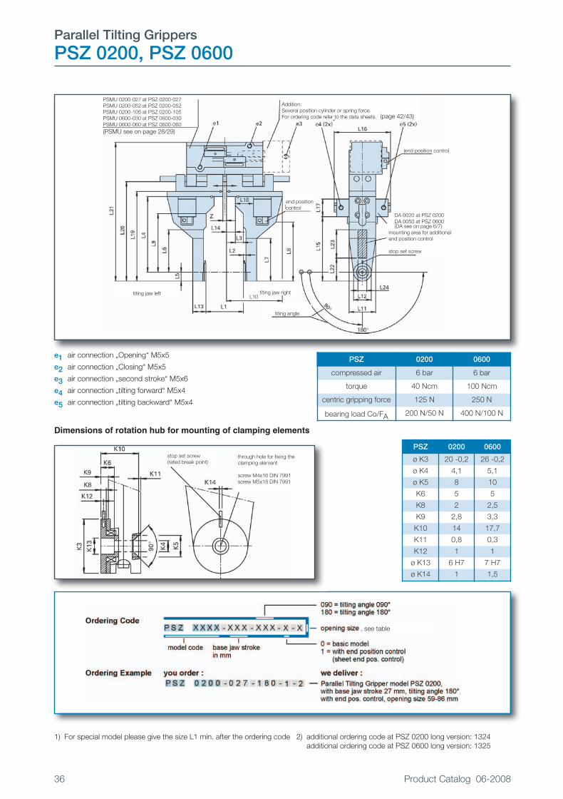
e1 air connection „Opening“ M5x5
e2 air connection „Closing“ M5x5
e3 air connection „second stroke“ M5x6
e4 air connection „tilting forward“ M5x4
e5 air connection „tilting backward“ M5x4
Dimensions of rotation hub for mounting of clamping elements
(PSMU see on page 28/29)
(DA siehe Seite 6/7)
PSMU 0200-027 at PSZ 0200-027PSMU 0200-052 at PSZ 0200-052PSMU 0200-105 at PSZ 0200-105PSMU 0600-030 at PSZ 0600-030PSMU 0600-060 at PSZ 0600-060
Addition:Several position cylinder or spring force.For ordering code refer to the data sheets.
DA 0020 at PSZ 0200DA 0050 at PSZ 0600(DA see on page 6/7)
mounting area for additionalend position control
stop set screw
end position control
end position control
titing jaw left titing jaw rightL10
titing angle
(page 42/43)
1) For special model please give the size L1 min. after the ordering code 2) additional ordering code at PSZ 0200 long version: 1324additional ordering code at PSZ 0600 long version: 1325
PSZ 0200 0600
ø K3 20 -0,2 26 -0,2
ø K4 4,1 5,1
ø K5 8 10
K6 5 5
K8 2 2,5
K9 2,8 3,3
K10 14 17,7
K11 0,8 0,3
K12 1 1
ø K13 6 H7 7 H7
ø K14 1 1,5
PSZ 0200 0600
compressed air 6 bar 6 bar
torque 40 Ncm 100 Ncm
centric gripping force 125 N 250 N
bearing load Co/FA 200 N/50 N 400 N/100 N
stop set screw(rated break point)
through hole for fixing theclamping element
screw M4x16 DIN 7991screw M5x18 DIN 7991
, see table
Katalog 2008_E.qxp:Innenseiten KAT-D-2007 26.09.2008 10:40 Uhr Seite 36

Product Catalog 06-2008 37
P MAll dimensions in mm
model PSZ 0200-027 PSZ 0200-052 PSZ 0200-105 long version 2)
opening size 0 1 2 3 0 1 2 3 0 1 2 3 —
L1 min. 19 39 59 special 19 64 109 special 47 131 215 special —
L1 max. 46 66 86 model 1) 71 116 161 model 1) 152 236 320 model 1) —
L2 2,8 2,8 2,8 —
L3 9 9 9 —
L4 85 85 85 +67,5
L5 10 10 10 —
L6 48 48 48 +67,5
L7 48 48 48 +67,5
L8 66 66 66 —
L9 66 66 66 +67,5
L10 53 63 73 53+L14 53 75,5 98 53+L14 108,5 108,5 137 53+L14+X —
L11 30 30 30 —
L12 20 20 20 —
L13 14,8 14,8 14,8 —
L14 — 10 20 (L1-Z):2-L3-0.25 — 22,5 45 (L1-Z):
2-L3-0.25 — 42 84 (L1-28.5):2+0,75-10 —
L15 72,5 72,5 72,5 +67,5L16 tiltingangle 90° 63,7 63,7 63,7 —
L16 tiltingangle 180° 73,2 73,2 73,2 —
L17 20x20 20x20 20x20 —
L18 20,4 20,4 20,4 —
L19 95 101 101 101 95 103 103 103 95 103 103 103 +67,5
L20 106 112 112 112 110 118 118 118 110 120,4 120,4 120,4 +67,5
L21 150,3 156,3 156,3 156,3 157 165 165 165 159,2 167,2 167,2 167,2 +67,5
L22 25 25 25 25
L23 33 33 33 100
L24 10 10 10 10
base jaw stroke 2x13,5 2x13,5 2x13,5 2x13,5 2x26 2x26 2x26 2x26 2x52,5 2x52,5 2x52,5 2x52,5 —
weight kg 0,9 1,0 1,0 1,0 1,1 1,2 1,2 1,2 1,6 1,7 1,7 1,7 —
Z 0,5 at base jaw closed 28,5 at base jaw closed
model PSZ 0600-030 PSZ 0600-060 long version 2)
opening size 0 1 2 3 0 1 2 3 —
L1 min. 32 52 72 special 32 82 132 special —
L1 max. 62 82 102 model 1) 92 142 192 model 1) —
L2 3,3 3,3 —
L3 15 15 —
L4 116 116 +90
L5 13 13 —
L6 74 74 +90
L7 74 74 +90
L8 95,5 95,5 +90
L9 91 91 +90
L10 67,5 77,5 87,5 67,5+L14 67,5 92,5 117,5 67,5+L14 —
L11 44 44 —
L12 26 26 —
L13 18 18 —
L14 — 10 20 (L1-Z):2-L3-0.75 — 25 50 (L1-Z):
2-L3-0.75 —
L15 101,5 101,5 +90L16 tiltingangle 90° 75,6 75,6 —
L16 tiltingangle 180° 87,6 87,6 —
L17 25x25 25x25 —
L18 30 30 —
L19 129 139 139 139 129 139 139 139 +90
L20 143 153 153 153 143 153 153 153 +90
L21 203,5 213,5 213,5 213,5 203,5 213,5 213,5 213,5 +90
L22 31 31 31
L23 56 56 146
L24 14 14 14
base jaw stroke 2x15 2x15 2x15 2x15 2x30 2x30 2x30 2x30 —
weight kg 1,9 2,0 2,0 2,0 2,2 2,3 2,3 2,3 —
Z 0,5 at base jaw closed
Katalog 2008_E.qxp:Innenseiten KAT-D-2007 26.09.2008 10:40 Uhr Seite 37

Parallel Tilting Grippers
PSZ 0201, PSZ 0601
38 Product Catalog 06-2008
e1 air connection „Opening“ M5x5
e2 air connection „Closing“ M5x5
e3 air connection „second stroke“ M5x6
e4 air connection „tilting forward“ M5x4
e5 air connection „tilting backward“ M5x4
Dimensions of rotation hub for mounting of clamping elements
1) for special model please give the size L1 min. after the ordering code. 2) additional ordering code at PSZ 0201 long version: 2291additional ordering code at PSZ 0601 long version: 2292
PSZ 0201 0601
K2 3 P9 4 P9
ø K3 30 h7 38 h7
ø K4 4,4 5,4
ø K5 8 10
K6 5 8
K7 1,5 2
K8 3,7 4,7
K9 4 5
K10 34 41
K11 1 3
K12 1,5 2
ø K13 8 H7 10 H7
K14 1,5 2
PSZ 0201 0601
compressed air 6 bar 6 bar
torque 40 Ncm 100 Ncm
centric gripping force 125 N 250 N
bearing load Co/FA 1000 N/400 N 2000 N/800 N
Addition:Several position cylinder or spring force.For ordering code refer to the data sheets.
DA 0020 at PSZ 0201DA 0050 at PSZ 0601
adjustment screws to limitthe tilting angle
mounting area for additionalend position control
end position control
end position control
stop set screw
fitting spring
titing jaw left
titing angle
stop set screw(rated break point)
through hole for fixingthe clamping element keyway
to u
se a
ltern
ativ
ely
(PSMU see on page 28/29)
(DA see on page 6/7)
PSMU 0200-027 at PSZ 0201-027PSMU 0200-052 at PSZ 0201-052PSMU 0200-105 at PSZ 0201-105PSMU 0600-030 at PSZ 0601-030PSMU 0600-060 at PSZ 0601-060
titing jaw right
, see table
Katalog 2008_E.qxp:Innenseiten KAT-D-2007 26.09.2008 10:40 Uhr Seite 38

Product Catalog 06-2008 39
P MAll dimensions in mm
model PSZ 0201-027 PSZ 0201-052 PSZ 0201-105 long ver-sion 2)
opening size 0 1 2 3 0 1 2 3 0 1 2 3 —
L1 min. 36,5 56,5 76,5 special 36,5 81,5 126,5 special 64,5 148,5 232,5 special —
L1 max. 63,5 83,5 103,5 model 1) 88,5 133,5 178,5 model 1) 169,5 253,5 337,5 model 1) —
L2 4 4 4 —
L3 10 10 10 —
L4 90 90 90 +75
L5 15 15 15 —
L6 53 53 53 +75
L7 68 68 68 +75
L9 71 71 71 +75
L10 53 63 73 53+L14 53 75,5 98 53+L14 108,5 108,5 137 53+L14+X —
L11 30 30 30 —
L13 35 35 35 —
L14 — 10 20 (L1-Z):2-L3-8 — 22,5 45 (L1-Z):
2-L3-8 — 42 84 (L1-28,5):2-L3-8 —
L15 82,5 82,5 82,5 +75L16 tiltingangle 90° 63,7 63,7 63,7 —
L16 tiltingangle 180° 73,2 73,2 73,2 —
L17 20x20 20x20 20x20 —
L18 17,7 17,7 17,7 —
L19 105 111 111 111 105 113 113 113 105 113 113 113 +75
L20 116 122 122 122 120,2 128,2 128,2 128,2 122,7 130,7 130,7 130,7 +75
L21 160,3 166,3 166,3 166,3 167 175 175 175 169 177 177 177 +75
L25 8 8 8 —
L26 2,8 2,8 2,8 —
base jaw stroke 2x13,5 2x13,5 2x13,5 2x13,5 2x26 2x26 2x26 2x26 2x52,5 2x52,5 2x52,5 2x52,5 —
L22 40 40 40 40
L23 35 35 35 110
L24 15 15 15 15
weight kg 1,3 1,4 1,4 1,4 1,5 1,6 1,6 1,6 1,9 2,0 2,0 2,0 —
Z 0,5 at base jaws closed 28,5 at base jaws closed
Typ PSZ 0601-030 PSZ 0601-060 long ver-sion 2)
opening size 0 1 2 3 0 1 2 3 —
L1 min. 47,5 67,5 87,5 special 47,5 97,5 147,5 special —
L1 max. 77,5 97,5 117,5 model 1) 107,5 157,5 207,5 model 1) —
L2 5 5 —
L3 15 15 —
L4 121 121 +108
L5 19 19 —
L6 78,5 78,5 +108
L7 97,5 97,5 +108
L9 98 98 +108
L10 67,5 77,5 87,5 67,5+L14 67,5 92,5 117,5 67,5+L14 —
L11 38 38 —
L13 44 44 —
L12 44 44 —
L14 — 10 20 (L1-Z): 2-L3-8,5 — 25 50 (L1-Z):2
-L3-8,5 —
L15 95 95 +108L16 tiltingangle 90° 75,6 75,6 —
L16 tiltingangle 180° 87,6 87,6 —
L17 25x25 25x25 —
L18 24,5 24,5 —
L19 140 150 150 150 140 150 150 150 +108
L20 154 164 164 164 154 164 164 164 +108
L21 214,5 224,5 224,5 224,5 214,5 224,5 224,5 224,5 +108
L25 8 8 —
L26 3 3 —
base jaw stroke 2x15 2x15 2x15 2x15 2x30 2x30 2x30 2x30 —
L22 48 48 48
L23 50 50 158
L24 18 18 18
weight kg 2,9 3,0 3,0 3,0 3,5 3,6 3,6 3,6 —
Z 0,5 at base jaws closed
Katalog 2008_E.qxp:Innenseiten KAT-D-2007 26.09.2008 10:41 Uhr Seite 39

Parallel Tilting Grippers
PSZ 1201, PSZ 3001
40 Product Catalog 06-2008
e1 air connection “Opening” R1/8x8 / R1/4x10
e2 air connection “Closing” R1/8x8 / R1/4x10
e4 air connection “tilting forward” M5x5,5 / R1/8x8
e5 air connection “tilting backward” M5x5,5 / R1/8x8
Dimensions of rotation hub for mounting of clamping elements
PSMU 1200 at PSZ 1201PSMU 3000 at PSZ 3001(PSMU see on page 30/31)
stop set screw
fitting spring
tilting jaw left tilting jaw right
end pos.control
end pos.control DA 0200 at PSZ 1201DA 0500 at PSZ 3001(DA see on page 6/7)
mounting area foradditonal endposition control
adjustmentscrews to limitthe tilting angle
tilting angle
stop set screw(rated break point)
keyway
to u
se a
ltern
ativ
ely
through hole for fixing the clampingelement
PSZ 1201 3001
compressed air 6 bar 6 bar
torque 400 Ncm 1000 Ncm
centric gripping force 600 N 1500 N
bearing load Co/FA 4000 N/1200 N 8000 N/3800 N
PSZ 1201 3001
K2 5,0 P9 6,0 P9
ø K3 52,0 h7 65,0 h7
ø K4 7,0 9,0
ø K5 12,0 15,0
K6 10,0 15,0
K7 3,0 3,5
K8 5,7 7,7
K9 6,0 8,0
K10 52,3 67,5
K11 6,2 9,0
K12 3,0 3,5
ø K13 12,0 H7 14,0 H7
K14 3,0 3,0
Katalog 2008_E.qxp:Innenseiten KAT-D-2007 26.09.2008 10:41 Uhr Seite 40

Product Catalog 06-2008 41
P Mmodel PSZ 1201-080 PSZ 1201-080 PSZ 3001-080 PSZ 3001-080
basic model special model basic model special model
opening size 0 3 0 3L1 min. 184.0 on request 227.0 on requestL1 max. 264.0 on request 307.0 on request
L2 6.0 6.0 8.0 8.0L3 15.0 15.0 16.0 16.0L4 180.5 180.5 226.5 226.5L5 26.0 26.0 32.5 32.5L6 100.0 100.0 114.5 114.5L7 126.0 126.0 147.0 147.0L9 124.5 124.5 156.7 156.7L10 114.0 86.0+L14 122.0 113.0+L14L11 52.0 52.0 65.0 65.0L13 58.5 58.5 76.5 76.5L14 28.0 (L1-Z) : 2-27.5 9.0 (L1-Z) : 2-36.5L15 144.5 144.5 175.5 175.5L16
tilting angle 90°90.6 90.6 129.6 129.6
L16tilting angle 180°
109.6 109.6 162.6 162.6
L17 35x35 35x35 50x50 50x50L18 26.5 26.5 31.5 31.5L19 180.5 180.5+L27 226.5 226.5+L27L20 200.5 200.5+L27 252.5 252.5+L27L21 262.5 262.5+L27 351.5 351.5+L27L22 72.0 72.0 75.0 75.0L23 54.0 54.0 65.0 65.0L24 25.0 25.0 35.0 35.0L25 8.0 8.0 8.0 8.0L26 5.0 5.0 5.0 5.0L27 — min. 20.0 — min. 20.0L28 2.0 2.0 2.0 2.0L29 92.0 92.0 134.0 134.0L30 98.0 98.0 141.0 141.0
base jaw stroke in mm 2x40 2x40 2x40 2x40weight kg 8.8 min. 8.8 13.3 min. 13.3
Z 73.0 at „base jaws closed” 136.0 at „base jaws closed”
All dimensions in mm
For special model please give size L1 min. after the ordering code!
Katalog 2008_E.qxp:Innenseiten KAT-D-2007 26.09.2008 10:41 Uhr Seite 41

Several Position Cylinder for
PSM, PSMU, PSZ
42 Product Catalog 06-2008
Addition : Several Position Cylinder for second stroke ZMZ
Mounting Hole for Ejector
ZMZ 0050-011 0050-029 0050-052 0200-013 0200-27 0200-52 0200-105 0600-016 0600-030 0600-060
for model PSM/PSMU0050-011
PSM/PSMU0050-029
PSM/PSMU0050-052
PSM/PSMU/0200-013
PSM/PSMU/PSZ
0200-027
PSM/PSMU/PSZ
0200-052
PSM/PSMU/PSZ
0600-105
PSM/PSMU/PSZ
0600-016
PSM/PSMU/PSZ
0600-030
PSM/PSMU/PSZ
0600-060
K1 30,1 30,1 41,5 31,3 31,3 43,8 70,3 57,3 57,3 57,3K2 25x25 25x25 25x25 35x35 35x35 35x35 35x35 50x50 50x50 50x50K3 12,5 12,5 12,5 17,5 17,5 17,5 17,5 25 25 25K4 32,1 38,1 66,5 37,3 42,3 67,8 108,8 58.8 61,8 61,8
K5 min. 5 5 5 5 5 5 5 5 5 5K6 M5x5,5 M5x5,5 M5x5,5 M5x6 M5x6 M5x6 M5x6 R1/8x9 R1/8x9 R1/8x9L10 17,5 17,5 17,5 19 19 19 19 35 35 35
All dimensions in mmRefer to technical specification sheets for dimensions and other details!
model PSM PSMU PSM PSMU PSM PSMU PSM PSMU PSM PSMU PSM PSMU
0030-0070030-0300030-052
0050-0110050-0290050-052
0200-0130200-027
0200-052 0200-1050600-0160600-0300600-060
ø d1 2,8 H6 2,8 H6 2,8 H6 2,8 H6 2,8 H6 2,8 H6 2,8 H6 2,8 H6 2,8 H6 2,8 H6 10 H6 10 H6
ø d2 2,6 2,6 2,6 2,6 2,6 2,6 2,6 2,6 2,6 2,6 8 H11 8 H11
L1 16,5 16,5 16,5 16,5 16,5 16,5 16,5 16,5 16,5 16,5 35 35
L2 3 3 3 3 3 3 3 3 3 3 5 5
L3 5,3 9,8 5 10,5 4,5 10,2 8,7 16,9 8,7 18,9 4,5 12,5
e1 = air connection „Opening“ (1x)e2 = air connection „Second stroke“ (4x)e3 = air connection „Gripping“ (1x)
base jaw top borderPSM or PSMU
pinion
end position control
optionseveral position cylinderfor second stroke
Katalog 2008_E.qxp:Innenseiten KAT-D-2007 26.09.2008 10:41 Uhr Seite 42

Spring Force for
PSM, PSMU, PSZ
Product Catalog 06-2008 43
Addition : Spring Force ZFS, with a mechanical spring for internal or external gripping force
Internal or external gripping force can also be used as safety in case of failure of air pressure!
Attachment for centering for PSM, PSMU, PSZ, all Parallel Grippers are deliverable with attachment forcentering
Ordering Code
Like PSM, PSMU or PSZ only with addition of „Attachment forcentering“
Ordering Example
PSMU 0050-011-100-0 with attachment for centering
P M
ZFS 0030-007 0030-011 0030-052 0050-011 0050-029 0050-052 0200-013 0200-27 0200-52 0200-105 0600-016 0600-030 0600-060
for modelPSM/PSMU0030-007
PSM/PSMU0030-011
PSM/PSMU0030-052
PSM/PSMU0050-011
PSM/PSMU0050-029
PSM/PSMU0050-052
PSM/PSMU/0200-013
PSM/PSMU/PSZ
0200-027
PSM/PSMU/PSZ
0200-052
PSM/PSMU/PSZ
0600-105
PSM/PSMU/PSZ
0600-016
PSM/PSMU/PSZ
0600-030
PSM/PSMU/PSZ
0600-060
B1 7,2 on on 9,5 on on 9,8 29,3 51,3 51,3 10 on on
ø B2 11 request request 15,5 request request 24,5 28 28 28 33,5 request request
All dimensions in mmRefer to technical specification sheets for dimensions and other details!
PSM/PSMUPSZ
0030 0050 0200 0600
d p6 7 10 12 26L -0,05 8,5 10,5 12 17,1
external gripping force atthe workpiece
internal gripping force atthe workpiece
gripping position
Katalog 2008_E.qxp:Innenseiten KAT-D-2007 26.09.2008 10:41 Uhr Seite 43

End Position Control
with LED
44 Product Catalog 06-2008
Technical data for End Position Control,electronic version– end position control with LED– contact-free adjustable– switch elements: permanent magnet,
PERMALLOY-SENSOR– connection cable: length about 2 m (6.5 ft),
3 cores, highly flexible– adjustment of connections– protected against short circuit and wrong
polarity– temperature range: -20°C to +80°C
(4° to 176°F)– voltage: 6–35 V– current: 250 mA– using current: smaller than 4 mA– switching frequency: max. 500 Hz– repeatable switching accuracy: +/- 0,1 mm– switching time: 1ms– protection: JP 66– no contact bouncing– high life expectancy, no moving parts– standard version PNP
Ordering ExampleActuator DA 0200-185-1-0 with end position control,electronic version, pluggable :
DA 0200-185-1-0 +0879
Ordering Example
End Position Switch,electronic version, withconnection cable highlyflexible, 5 m long, asreplacement part:
7399+0886
* Different end positionswitches are possible,please consult factory orcatalog.
** Attention:not pluggable for model:PSM 0050-011/PSM 0050-029DM 0020-090/DM 0050-090DSK 0020-090/DSK 0020-180DSK 0050-090/DSK 0050-180
End position control, electronic version
additional Ordering Code
for model pluggable **connection cable5 m highly flexible
NPN
DA... 0879 0887 0587PSM... 0879 0887 0587
PSMU... 0879 0887 0587PSM+ZMZ... -- 1281 1285
PSMU+ZMZ... -- 1281 1285LM... 0879 0887 0587DM... 0879 0887 0587DSK... 0880 1282 0588SM... 0879 0887 0587PSZ... -- 1283 892
PSZ+ZMZ -- 1284 1286HPA... 0879 0887 0587
Endschalter als Ersatzteile
ordering code additional ordering code
for modelelectronic
versionconnection cable5 m highly flexible
NPN
DA 0050–DA 6000PSM 0050–PSM 0600PSMU 0050–PSMU 0600DSK 0050+DSK 0200DM 0050–DM 0500SM 0020–SM 0200LM 0050–LM 0500DSK 0020*PSZ*HPA
7399 0886 0362
DA 0020+PSM 0030DM 0020+PSMU 0030DSK 0020*
7875 0886 0362
ZMZ 0050–ZMZ 0600* 7878 0886 0362
ZMZ 0030 7877 0886 0362
PSZ 0200+PSZ 0600 7876 0886 0362
DA 0050–DA 6000PSM+PSMU 0050-52PSM 0200–PSM 0600PSMU 0200–PSMU 0600DSK 0200+DM 0050-180DM 0200–DM 0500SM 0020–SM 0200LM 0050–LM 0500PSZ*HPA
7885 -- 0362
DA 0020+PSM 0030DM 0020-180+PSMU 0030
7888 -- 0362
connection cable,pluggableAttention: not pluggablefor model **
7889 0886 -
end position switch withoutconnection cable, pluggable
connectioncable,pluggable
Katalog 2008_E.qxp:Innenseiten KAT-D-2007 26.09.2008 10:41 Uhr Seite 44

Linear Module, Tilting Module, Double Tilting Head
LM, SM, DSK
Product Catalog 06-2008 45
The PTM-Linear Modules – LM – work with ourPTM-Actuators. In contrast to the normal linearunits, the PTM-Linear Modules use a crank.Therefore there are many advantages. This causes asinucidal move of the slide with high positioningaccuracy and smooth end positioning. The reducedend speed is supported by the end positiondamping of the PTM-Actuators – DA –. Themovements of the slide will be shock-free.
The slide strokes are continuous adjustable between0 and 25, 30, 52 or 90 mm.
The PTM-Tilting Module – SM – in connectionwith a fix mounted Parallel Gripper – PSM – is ableto tilt a workpiece by 90° from a horizontal positionto a vertical position and back. The position of theworkpiece will not be changed.
The PTM-Double Tilting Head – DSK – gives theadditional possibility to tilt a workpiece with adefined tilting angle of 90° or 180°. Other tiltingangles on request.
P M
Katalog 2008_E.qxp:Innenseiten KAT-D-2007 26.09.2008 10:41 Uhr Seite 45

Linear-Module
LM 0020, LM 0050, LM 0200, LM 0500Brief technical data
46 Product Catalog 06-2008
Material:– aluminum hard or black anodized– steel parts of stainless material or corrosion resistant– shorttime gas nitration
Operating or mounting position: – any position desired
Operating temperature: – -10° to +80°C (4° to 176°F)
Operating media: – filtered oiled or filtered oil-free air– Attention: only oil-free air should be used at low rotation speed
as interruptions could harm the smooth process
Operation pressure: – maximum 6 bar (specs are based on 6 bar = 88 psi)
Jaw stroke: – sinucidal movement– stroke range adjustable via dovetail guides with clamping screw
Guide:– precision grinded guides– stainless steel shafts and ball-type bushings
Actuation: – Pneumatic Mini Actuator with end position damping
End position control with LED: – please consult our sheet „End position control“ (Page 44).
Installation recommendation: – to ensure long life of our devices the use of throttle valves
is highly recommended.
Katalog 2008_E.qxp:Innenseiten KAT-D-2007 26.09.2008 10:41 Uhr Seite 46

Product Catalog 06-2008 47
LM 0200 / LM 0500end position control
LM 0020 / LM 0050
P M
a, b mounting surfacec, d, e mounting alternativesf 2 threaded holes for air connectiong connection cable for end position control
A model with end position control
X model of actuator DA
model LM 0020-025 LM 0050-030 LM 0200-052 LM 0500-090
X DA 0020-185 DA 0050-185 DA 0200-185 DA 0500-185
ø d1 6 8 12 16
d2 M4x6 M4x6 M5x8 M6x12
ø d3 — 8 10 11
ø d4 — 4,5 5,5 6,4
ø d5 10 10 12 15
ø d6 5,5 5,5 6,5 9
d7 M5x4 M5x4,5 M5x5,5 R1/8x8
L1 41 45,5 64,3 86,5
L2 104 123 179,5 284,5
L3 68 82 107 162
L4 73,6 +0,6 -0,8 87,6 +0,6 -0,8 109,6 +0,6 -0,8 162,6 +0,6 -0,8
L5 2,8 2,8 1,3 0,3
L6 37 42 61 103
L7 40 45 64 90
L8 33,5 34,5 52 71
L9 18,5 21 30,5 51,5
L10 7,5 11 12,3 15,5
L11 0,3 0,5 0,3 0,5
L12 53 58 80 130
L13 max. 12,5 15 26 45
L14 53 64 100 143
L15 56,8 ±0,4 71,2 ±0,4 93,2 ±0,4 141,2 ±0,4
L16 6 6 9,5 15
L17 27 27 40 53
L18 6 9 8 12
L19 12 12 20 32
L20 35 40 52 90
L21 — 4 5 8
L22 15 22 24,5 31
L23 20 22 41 45
L24 10 13 18,5 26
L25 — — 2,5 1,9
L26 — — 55,9 76,4
L27 — — 60,8 81,4
A1 2 3,5 1 —
stroke in mm 25 30 52 90
weight in kg 0,3 0,6 1,5 4,7
Katalog 2008_E.qxp:Innenseiten KAT-D-2007 26.09.2008 10:41 Uhr Seite 47

Tilting Module
SM 0020, SM 0050, SM 0200
48 Product Catalog 06-2008
model SM 0020 SM 0050 SM 0200
X DA 0050-095 DA 200-095 DA 0500-095
d1 M5x8 M5x8 M6x10
d2 M5x4 M5x5,5 R1/8x8
d3 M5x8 M5x8 ø10
L1 55 68 99,5
L2 84 ±0,5 97,8 ±0,5 127 ±0,5
L3 70 +0,4 -0,6 85 +0,4 -0,6 124 +0,4 -0,6
L4 75,6 +0,6 -0,8 90,6 +0,6 -0,8 129,6 +0,6 -0,8
L5 2,8 2,8 2,8
L6 45 55,5 82
L7 19 20,5 32
L8 40 41 60
L9 29,5 31,4 38,5
L10 6 6 8
L11 72 ±0,7 85,8 ±0,7 111 ±0,7
L12 16 20 25
L13 16 20 30
L14 59,2 ±0,4 74,2 ±0,4 108,2 ±0,4
L15 5 5 5
L16 30 31 50
L17 50 65 88
L18 20x20 25x25 35x35
A1 63 76 107,5
"A" kg 4,0 6,0 10,0
weight in kg 0,3 0,6 1,7
a mounting surface for additional equipment to be tilted
b mounting surface
c mounting alternatives
e 4 threaded holes for air connection and as mounting alternatives
g connection cable for end position control
A model with end position control
X model of actuator
tilting angle 90°
end position control
Katalog 2008_E.qxp:Innenseiten KAT-D-2007 26.09.2008 10:41 Uhr Seite 48

Double Tilting Head
DSK 0020, DSK 0050, DSK 0200Brief technical data
Product Catalog 06-2008 49
Material:– aluminum hard or black anodized– steel parts of stainless material or corrosion resistant– shorttime gas nitration
Operating or mounting position: – any position
Operating temperature: – -10° to +80°C (14° to 176°F)
Operating media: – filtered oiled or filtered oil-free air– Attention : only oil-free air should be used at low rotation speed
as interruptions could harm the smooth process
Operating pressure: – maximum 6 bar (specs are based on 6 bar = 88psi)
Movement: – tilting 90°– rotation 180°
Actuation: – Pneumatic Mini Actuator with end position damping
End position control with LED: – please consult our sheet „End position control“
Model and installation accessories:
– the adapter or mounting surface, which is delivered with the basic unit,is prepared for the mounting of our Parallel Gripper PSM.However any other equipment of the customers choise (for examplesuction grippers) can be mounted.
Installation recommendation: – to ensure long life of our devices the use of throttle valves is highly
recommended.
P M
Katalog 2008_E.qxp:Innenseiten KAT-D-2007 26.09.2008 10:41 Uhr Seite 49

Double Tilting Head
DSK 0020, DSK 0050, DSK 0200
50 Product Catalog 06-2008
a mounting surface for tilting and rotating additional equipment
b mounting surface
c mounting alternative
d holes for mounting the additional equipment
e 4 threaded holes for air connection „tilting“and as mounting alternatives
f 2 threaded holes for air connection „rotation“
g connection cable for end position control
A model with end position control
X model of actuator „tilting“
Y model of actuator „rotation“
stop at model with rotationangle 90°
end positioncontrol
tilting angle 90°
rotation angle 180°
rotation angle 90°
end position control d* hole pattern for DSK 0020 only
Katalog 2008_E.qxp:Innenseiten KAT-D-2007 26.09.2008 10:41 Uhr Seite 50
Product Catalog 06-2008 51
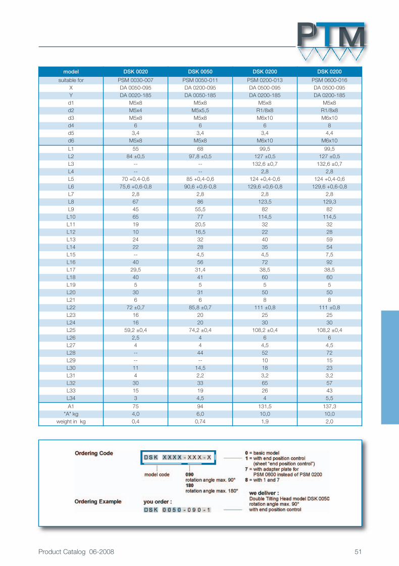
model DSK 0020 DSK 0050 DSK 0200 DSK 0200
suitable for PSM 0030-007 PSM 0050-011 PSM 0200-013 PSM 0600-016X DA 0050-095 DA 0200-095 DA 0500-095 DA 0500-095Y DA 0020-185 DA 0050-185 DA 0200-185 DA 0200-185d1 M5x8 M5x8 M5x8 M5x8d2 M5x4 M5x5,5 R1/8x8 R1/8x8d3 M5x8 M5x8 M6x10 M6x10d4 6 6 6 8d5 3,4 3,4 3,4 4,4d6 M5x8 M5x8 M6x10 M6x10
L1 55 68 99,5 99,5L2 84 ±0,5 97,8 ±0,5 127 ±0,5 127 ±0,5L3 -- -- 132,6 ±0,7 132,6 ±0,7L4 -- -- 2,8 2,8L5 70 +0,4-0,6 85 +0,4-0,6 124 +0,4-0,6 124 +0,4-0,6L6 75,6 +0,6-0,8 90,6 +0,6-0,8 129,6 +0,6-0,8 129,6 +0,6-0,8L7 2,8 2,8 2,8 2,8L8 67 86 123,5 129,3L9 45 55,5 82 82L10 65 77 114,5 114,5L11 19 20,5 32 32L12 10 16,5 22 28L13 24 32 40 59L14 22 28 35 54L15 -- 4,5 4,5 7,5L16 40 56 72 92L17 29,5 31,4 38,5 38,5L18 40 41 60 60L19 5 5 5 5L20 30 31 50 50L21 6 6 8 8L22 72 ±0,7 85,8 ±0,7 111 ±0,8 111 ±0,8L23 16 20 25 25L24 16 20 30 30L25 59,2 ±0,4 74,2 ±0,4 108,2 ±0,4 108,2 ±0,4L26 2,5 4 6 6L27 4 4 4,5 4,5L28 -- 44 52 72L29 -- -- 10 15L30 11 14,5 18 23L31 4 2,2 3,2 3,2L32 30 33 65 57L33 15 19 26 43L34 3 4,5 4 5,5
A1 75 94 131,5 137,3"A" kg 4,0 6,0 10,0 10,0
weight in kg 0,4 0,74 1,9 2,0
P M
Katalog 2008_E.qxp:Innenseiten KAT-D-2007 26.09.2008 10:41 Uhr Seite 51

Swivel Distributor
SLE 1014Brief technical data
52 Product Catalog 06-2008
Material:– aluminum hard or black anodized– steel parts of stainless material or corrosion resistant– shorttime gas nitration
Operating or mounting position: – any position
Operating temperature: – -10° to +80° C (14° to 176° F)
Operating pressure: – maximum 7 bar
Tilting angle: – 90° or 180°– adjustable ±5°
Swivel distributor:
– double bearing– friction loss of maximum 40 Ncm– maximum radial load 5000 N– maximum axial load by pushing pressure 2000 N– maximum axial load by pulling pressure 500 N
Pneumatic connections:– 10 connections with threaded holes M5 (in)– 10 connections with threaded holes M5 (out)
smallest diameter of air holes is 1,5 mm (0,006 in)
Electronic connections:
– 14 connections pluggable, 3 lane (out)– 1 connection pluggable, 16 lane (in)
with straight or L-plug– wire cross section 0,14 mm2
Weight: – 1,5 kg
Refer to technical specification sheet on page 53 for dimensions and other details.
Katalog 2008_E.qxp:Innenseiten KAT-D-2007 26.09.2008 10:42 Uhr Seite 52

Product Catalog 06-2008 53
Attachment options with actuators of model DA 0200 – DA 3000 and HPA, information and data sheets on request.
P M
a 10 air connections M5 - inb 10 air connections M5 - out (5 on each side)c 14 electric connections - out (7 on each side)d 1 electric connection 16 cores - in
(with straight plug or L-plug possible)e 10 air connections M3, possibility for direct
connectionf 2 adjustment screws for 180° ±5°g 4 threaded holes for mounting M6/12 longh 4 threaded holes for mounting M6/12 longl 8 threaded holes for mounting M6/10 long
All dimensions in mm
Co radial = 5000 N
weight = 1,5 kg
tilting angle
view X
Katalog 2008_E.qxp:Innenseiten KAT-D-2007 26.09.2008 10:42 Uhr Seite 53

Formulas
54 Product Catalog 06-2008
For selection of the proper PTM-Actuator the following formulas of moment of inertia and gravity may be used:
If you want to calculate the size of the PTM-Actuators theoretically, either the moment of inertia or the rotatingtime of the moved masses must be known.
In the examples below it is assumed, that the axis of the actuator is vertical. There is no influence of gravity inthis position. For other positions the influence of gravity must be considered and will be calculated according tothe general formulas.
The moment of inertia of the moved masses can be calculated using the following formulas:
m = m1 + m2 +...mn2 2
J = 16 m · (d2 + 3 h
2)1 4
J = 8 m · d21
J = 16 m · (d2 + d2 +1 4a i J = 10 m · d
21
J = 12 m · (d2 + b
2)1
J = 12 m · (d2 + 4b2)1
J = 8 m · (d2 + d
2)1a i
2J = m1 · r1 · m2 · r2 · ...mn + rn
J = E (m · r2)
3h2 )
Katalog 2008_E.qxp:Innenseiten KAT-D-2007 26.09.2008 10:42 Uhr Seite 54

Product Catalog 06-2008 55
General Terms and Conditions of Business
Sales, Delivery and Payment Conditionsof P.T.M. PRODUKTION – Puchheim1. ScopeThese Terms & Conditions of Business shall apply to all contracts, unless they are amended or excluded by our express written permission.
2. Offer and conclusion of contractAn order shall only be deemed accepted when it is confirmed by ourselves in writing. Until that time the offer shall not be binding. Orders, supplementary instructions, amendments etc.given by telephone or telegraph, or verbally, shall not be valid unless they are confirmed in writing by ourselves. The documents contained in our printed material, such as specifications ofweights and measures, illustrations and descriptions, shall only be approximate, nor shall there be any obligation to report amendments thereto. Weights, measures, illustrations, designati-ons and drawings shall only be binding in execution if they have been explicitly confirmed in writing. We hereby reserve our objective and intellectual property rights to all illustrations, draw-ings, sketches and other documents. These must not be duplicated or made accessible to others without our permission and must be returned on demand. The Customer must ensurethat the production drawings he provides do not infringe the copyrights of Third Parties. We shall have no duty vis-à-vis the Customer to check whether any copyrights of Third Parties areinfringed by the issue of offers based on production drawings which he has sent. Should liability nevertheless transpire on our part, the Customer must indemnify us for any claims of re-gression. Designs will only be supplied for payment.
3. PricesPrices will be in EURO, either ex works or ex salesroom, as we deem fit. Packaging, freighting, postal chares and insurance are not included in our prices. The same shall apply to partdeliveries and express deliveries. Packaging and dispatch will be arranged as we think best, a charge being made for our costs actually incurred, but without obligation on or part. Packa-ging cannot be taken back. Non-list goods will be subject to a supplement dependent on the special manufacture concerned, and this must be agreed prior to issue of order. Shouldagreement not be reached, or should it not be possible to set a precise price, a supplement shall be calculated for this based on the actual costs incurred. Our prices are governed by cur-rent business conditions and currency arrangements. Should significant amendments in cost accounting prove necessary due to charges for raw and auxiliary materials, to increases inwages or freight charges, or due to amendments thereto, we shall be entitled to adjust said prices. Should a price be raised, the increased price shall be deemed agreed by way of a firmobligation on the part of the Customer.
4. Terms and conditions of paymentUnless agreed otherwise in the written confirmation, payment must be made no later than 30 days following date of invoice, either in cash or by bank transfer, strictly net and excluding anyoffset or retention. This shall also apply to part deliveries. The commencement of the period of grace for payment shall be governed by the date of invoice. In the case of items speciallyconstructed and manufactured for an order, payment must be in cash, strictly net, all charges paid, one-third payment being made on order, one-third on delivery, and the remainder 30days following invoice. All receivables due from the Customer shall be payable immediately should he fall into arrears of payment or should he infringe any contractual agreements, inclu-ding these provisions. This shall also apply to suspension of payments or initiation of a creditors’ composition or of bankruptcy proceedings on the part of the Customer. We shall be entit-led to require security against our receivables at any time. We shall have no obligation to accept cheques or bills of exchange. Should we accept them, the debt concerned shall be repaidonly when they are cashed. The Customer must pay the discount fee, the charges and all costs, whether in or out of court, associated with collection of cheques or bills of exchange.Should payments be deferred or be made later than agreed, we shall be entitled to charge interest amounting to 6% above the discount rate of the Deutsche Bundesbank, without anyparticular arrears procedure, while reserving the right to claim further damages. Deliveries to firms unknown to us will be made only in return for prior payment or cash on delivery as a con-signment with declared value. Specially produced items will only be supplied to such firms in return for a payment on account, such payment on account being subtracted from the resi-dual payment.
5. DeliveryAll delivery times will be set after careful consultation and agreement. However, they shall not be legally binding. If delivery times are to be met, the Customer must fulfil his contractualduty. Delivery time shall have been met if, prior to its expiry, the item for delivery has left the works, or we have declared ourselves ready and willing to dispatch it. Delivery time shall be ex-tended appropriately should unforeseen circumstances transpire which are beyond our control (e.g. disruption of business, lockouts, delays to supply of raw materials etc.). We shall in-form the Customer of the beginning and end of such disturbances as far as we are able. The Customer cannot reject part deliveries. We shall be entitled to make part deliveries at theCustomer’s expense. Should we discover after conclusion of contract that the Customer is in financial difficulties, we may require security for counter-performance or declare that we shallnot undertake performance. In the latter case, the Customer must pay all expenses incurred to date and pay damages for non-execution of delivery. Should we fall into arrears throughgross negligence, the Customer may claim damages in compensation amounting to a maximum of 0.5 percent of the price of the delayed delivery for each full week of arrears. All otherclaims for damages are hereby excluded.
6. Transfer of riskOnce material has been handed over to an agent outside our business or freight carrier, or as soon as it has been dispatched from our works, risk shall be transferred to the Customer,even if carriage-paid delivery has been agreed. We shall only replace goods lost or damaged in transit on the basis of a new order, whereby we shall charge our prices as valid from time totime.Any discrepancies in the dispatch note or invoice must be reported in writing immediately after reception of goods. We shall only take out transport insurance if the Customer so instructsus, and at his expense. Should dispatch be delayed through fault of the Customer, risk shall be transferred to the Customer from the day when we were ready and willing to make dis-patch. In such cases we shall be entitled to effect insurance against all likely risks at the Customer’s expense.
7. Liability for defectsDefective deliveries shall be replaced free of charge within the statutory period of limitation. We give a guarantee for a period of one year, beginning on the day of delivery. The Customermust give us an opportunity to confirm that complaints are justified, by inspecting the items concerned. We shall accept no liability for parts which have suffered premature obsolescencebecause of the nature of their materials or because of the way they have been used; nor damage due to natural wear and tear, inappropriate or careless handling, excessive stress andstrain, unsuitable operating resources, chemical or electrical effects, meteorological or other natural influences. In the case of products sent in for finishing, refurbishment or alteration –even those of our own manufacture – we accept no liability for their behaviour under hardening or processing. Should the material become damaged under processing, we shall be paid acorresponding part of the agreed price. In the case of specially produced goods, we shall be liable for culpable defective construction or imperfect execution and for defective materialsonly if we have provided them and only insofar as we ought to have identified the defect when applying professional care. In the case of manufacture in accordance with a Customer’sdrawing, we shall be liable only for execution in accordance with drawing. Should we be commissioned with the solution of structural tasks, liability for defects can only be claimed if theCustomer can prove that the product culpably fails to correspond to the current state of technology. The Customer can only require, on grounds of liability for defect, that unusable partsbe repaired, or that a new delivery be made thereof, as we think fit. In all the aforesaid cases, any other claims by the Customer, of whatever kind, particularly by way of rescission, diminu-tion or compensation, including payment of consequential damages, is hereby excluded. However, the Customer may require rescission or diminution, as he thinks fit, if a replacement de-livery or repair is impossible or defective, has been culpably delayed by ourselves, or unjustly refused. The Customer shall pay all costs arising from unjustified complaints. Liability fordefect shall cease if the Customer or a Third Party have undertaken repairs without our permission.
8. Proviso of ownershipThe item under delivery shall remain our property until all receivables, including future receivables, arising from business relations with the Customer have been paid. This shall apply even ifindividual receivables, or all receivables, are included in a current account and the balance is struck and recognised. Assertion of such proviso of ownership shall not signify withdrawalfrom contract. If an item of our goods is combined by the Customer with other products to create a uniform article, it is hereby agreed that the Customer transfer to us joint proportionalownership thereof as set out in Section 947, Paragraph 1 of the Civil Code and jointly maintain the article for us. The Customer shall be entitled to resell the article in the course of normalbusiness. However, he must assert our proviso of ownership vis-à-vis the buyer. He cedes to us here and now all claims which may accrue to him from the buyer from such resale. TheCustomer shall remain entitled to collect these receivables even after cession. Our right to collect such receivables ourselves shall not be affected thereby; however, we hereby agree notto collect such receivables as long as the Customer fulfils his duties of payment in a due and proper way. All proceeds due to the seller from such cession must be transferred to us imme-diately after receipt in each case. We may require the Customer, if necessary, to name to us the debtors owing such ceded receivables and to inform said debtors of this cession. Shouldthe article delivered be resold together with other goods not belonging to us, the Customer’s receivable due from the buyer shall be deemed to be ceded to the amount of the delivery priceagreed between ourselves and the Customer. The Customer must inform us immediately of any attachments by Third Parties upon goods supplied under proviso of ownership or uponceded receivables. This right of ownership shall also apply vis-à-vis the carrier to whom the goods are entrusted by application of the Customer or at our instance. This proviso of owner-ship shall be limited inasmuch as ownership of goods supplied shall be immediately transferred to the buyer, and the buyer be entitled to all ceded receivables, as soon as he has paid thereceivables for which he is liable to ourselves. Should the value of the securities accruing to the seller exceed total receivables due from the buyer by more than 30 percent, the seller shallhave a duty, should the buyer so require, insofar to release such securities as he sees fit. The Buyer’s right to ownership of goods under proviso shall cease should he fail to fulfil his dutiesunder this or any other contract. The seller shall then be entitled to take possession of such goods under proviso himself and, irrespective of the buyer’s duties of payment, or other duties,towards the seller, to realise their value as best he can by a sale at market rates or by way of auction. The proceeds of such realisation will be offset against the buyer’s liabilities, followingdeduction of costs. Any surplus shall be paid to him.
9. Place of fulfilment and jurisdictionThe works shall be the place of fulfilment for all obligations due by both Parties under this contract. The place of fulfilment for payment shall be Munich. Munich shall be the sole place ofjurisdiction for all legal disputes, including any disputes involving procedures for bills of exchange or cheques. However, we may also sue the Customer before the courts of his generalplace of jurisdiction. Only German law shall apply between the contracting parties. Should one or more of these contractual conditions be ineffective or invalid, the validity of the othersshall not be affected thereby.
10. Customer’s conditions of purchaseShould the Customer’s conditions of purchase conflict with these Terms and Conditions, they shall not be binding on us, even if the Customer has made them basic conditions and wehave not explicitly protested.
P M
Katalog 2008_E.qxp:Innenseiten KAT-D-2007 26.09.2008 10:42 Uhr Seite 55

P.T.M. – PRODUKTION tech. -mech. Geräte GmbHBoschstraße 4 · 82178 PUCHHEIM
Fon +49-(0)89-8002151 · Fax +49-(0)89-8002952E-Mail: [email protected]
Internet: www.ptmgmbh.com
We're constantly working to improve our products. Therefore, we reserve the right for technical changes. All dimensions in mm, free tolerances DIN 7168 medium.
Katalog 2008_E.qxp:Innenseiten KAT-D-2007 26.09.2008 10:42 Uhr Seite 56