protect rcs brochure - · pdf fileavailability of all your global industrial applications ......
TRANSCRIPT

Protect RCS
BROCHURE
JUNHO 2013

PROTECT RCS
THYRISTOR CONTROLLED INDUSTRIAL RECTIFIER & BATTERY CHARGER
Input:220 / 230 / 240 VAC 1 phase380 / 400 / 415 VAC 3 phase
Output:24 VDC; 25 – 1000 A48 VDC; 25 – 1000 A
110 VDC; 25 – 1000 A125 VDC; 25 – 1000 A220 VDC; 25 – 1000 A
AEG Power Solutions rectifi ers assure permanent availability of all your global industrial applications including oil, gas & petrochemical, power generation, transportation and other infrastructure.
The Protect RCS DC system has been developed and designed to provide high reliability power supply and battery charging capability.
The Protect RCS DC system is a thyristor-controlled rectifi er suitable for charging nickel-cadmium or lead-acid batteries while supplying DC loads. It can also be used without batteries as a direct power supply.
The rectifi er is built from independent building blocks and can be equipped with optional equipment like distribution boards, diode droppers etc. build inside or in a separate cubicle.
The cabinets are fl oor mounted and can be designed to meet specifi c environmental requirements. The batteries are mounted in free-standing racks or in cabinets together with or separated from the rectifi er.
Features & Benefi ts »Standard system configurations »Heavy duty design »Proven microprocessor-controlled thyristor technology »Building block modular design »High MTBF and low MTTR »Built-in protection »Digital processing and setting of all parameters »Monitoring of all parameters via the front panel display »Built-in intelligent battery management »Temperature-compensated charge voltage regulation »Manual or automatic high rate charge »Parallel operation »Alarm- and event logger, with a date and time-stamped event log memory »Ease of installation, start-up & maintenance » International service support

2
PROTECT RCS – SYSTEMINPUT
Nominal input voltage Single phase (SPRe) 230 V ±10 % (+15 % – 20 % functional)Three phase (TPRe) 400 V ±10 % (+15 % – 20 % functional)
Frequency 50 Hz or 60 Hz, ±6 %
Power factor Single phase system (SPRe) ~ 0.67 / Three phase system (TPRe) ~ 0.81
OUTPUT
Voltage (UDC) 24, 48, 110, 125, 220 VDC
DC voltage settings range Floating charge – 75 % – 125 % of UDC nominal at full load and nominal mains voltage (±10 %) High-rate charge – 75 % – 135 % of UDC nominal at full load and nominal mains voltage (0 / +10 %)
Commissioning charge – 75 % – 140 % of UDC nominal at half load and nominal mains voltage (0 / +10 %)
Static voltage regulation ±0.5 % at float voltage, 0 – 100 % DC load variations, input nominal voltage ±10 %, frequency ±6 %, temp. range 0 °C to +40 °C
Dynamic voltage regulation 10 – 100 %, 100 % – 10 % load step – deviation 5 %
DC ripple voltage <2 % rms of UDC nominal with battery connected (standard battery capacity 5 x nominal current) 2.5 % rms typically (max 5 %) of UDC nominal battery not connected (standard battery capacity 5 x nominal current)
DC current According to range
Current settings range 0 – 100 %
DC current regulation 0 / +2 % of current limit
Long-term stability 0.15 % per 1000 hrs
Temperature coefficient <0.02 % per °C
Charging characteristic Constant current / constant voltage (I/U as per IEC 478 1) during float charge
Insulation resistance >200 MW / 500 V DC
Input / output isolation 2,500 V AC between input / output and electrical earth
MECHANICAL
Degree of protection IP21 according to IEC 60529
Equipment colour RAL 7035, powder coated, textured paint
Dimensions & weight According to range
Acoustic noise @ 1 m 45 – 65 dB(A)
Connections Bottom
ENVIRONMENTAL
Type of cooling Natural convection up to 75 A / 220 V and top forced air ventilation with optional redundant n+1 fan
Operating temperature 0 °C to +40 °C with a de-rating of 1.25 % / °C between 40 °C and 55 °C
Storage temperature -25 °C to +70 °C
Operating humidity 10 % to 95 % R H Non-Condensing
Installation height 0 to 1,000 m – De-rating @ 1 % per 100 m above 1,000 m up to 3,000 m
Seismic BELLCORE GR-63-CORE issue 1 for Zone 1, Zone 2, Zone 3 and Zone 4 (systems max 500 kg)
STANDARDS
Safety IEC / EN 62040-1-2
EMC IEC / EN 61000-6-2,-4 , IEC / EN 62040-1-2
Performance IEC / EN 62040-1-2, IEC 601146-1-1
Approvals & certification CE-Label, NFC 58-311
PROTECT RCS – SINGLE PHASE RANGE / THREE PHASE RANGESPRe – Single Phase Range TPRe – Three Phase Range
BATTERY VOLTAGE (VDC) 24 48 110 24 48 110 125 220
Output Current (A) 25 25 25 25 25 25 25 25
50 50 50 50 50 50 50 50
75 75 75 75 75 75 75
100 100 100 100 100 100 100
150 150 150 150 150
200 200 200 200 200
300 300 300 300 300
400 400 400 400 400
500 500 500 500 500
600 600 600 600 600
800 800 800 800 800
1000 1000 1000 1000 1000
3
STANDARD CONFIGURATION
AND OPTIONS
Standard system
The Protect RCS range of systems has been preconfigured with a number of the most commonly requested features built-in as standard. These systems are available “off-the-shelf” with standard drawings and standard user documentation.
Standard configuration
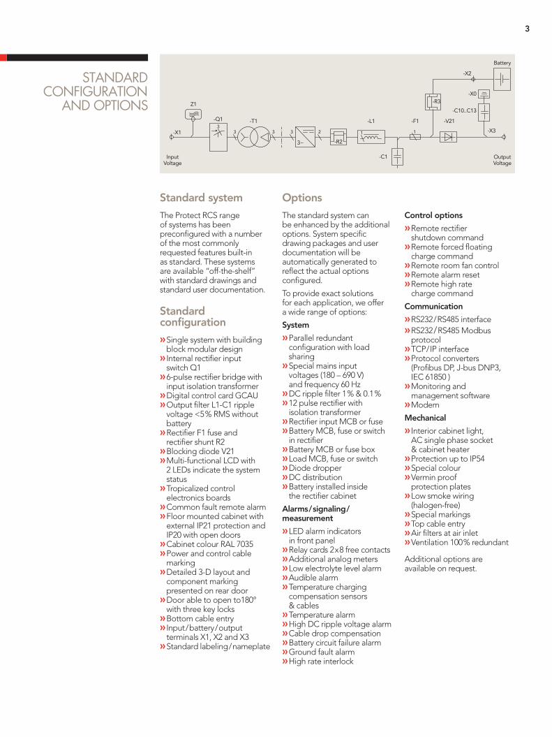
»Single system with building block modular design » Internal rectifier input switch Q1 »6-pulse rectifier bridge with input isolation transformer »Digital control card GCAU »Output filter L1-C1 ripple voltage <5 % RMS without battery »Rectifier F1 fuse and rectifier shunt R2 »Blocking diode V21 »Multi-functional LCD with 2 LEDs indicate the system status »Tropicalized control electronics boards »Common fault remote alarm »Floor mounted cabinet with external IP21 protection and IP20 with open doors »Cabinet colour RAL 7035 »Power and control cable marking »Detailed 3-D layout and component marking presented on rear door »Door able to open to180° with three key locks »Bottom cable entry » Input / battery / output terminals X1, X2 and X3 »Standard labeling / nameplate
Options
The standard system can be enhanced by the additional options. System specific drawing packages and user documentation will be automatically generated to reflect the actual options configured.
To provide exact solutions for each application, we offer a wide range of options:
System
»Parallel redundant configuration with load sharing »Special mains input voltages (180 – 690 V) and frequency 60 Hz »DC ripple filter 1 % & 0.1 % »12 pulse rectifier with isolation transformer »Rectifier input MCB or fuse »Battery MCB, fuse or switch in rectifier »Battery MCB or fuse box »Load MCB, fuse or switch »Diode dropper »DC distribution »Battery installed inside the rectifier cabinet
Alarms / signaling / measurement
»LED alarm indicators in front panel »Relay cards 2 x 8 free contacts »Additional analog meters »Low electrolyte level alarm »Audible alarm »Temperature charging compensation sensors & cables »Temperature alarm »High DC ripple voltage alarm »Cable drop compensation »Battery circuit failure alarm »Ground fault alarm »High rate interlock
Control options
»Remote rectifier shutdown command »Remote forced floating charge command »Remote room fan control »Remote alarm reset »Remote high rate charge command
Communication
»RS232 / RS485 interface »RS232 / RS485 Modbus protocol »TCP / IP interface »Protocol converters (Profibus DP, J-bus DNP3, IEC 61850 ) »Monitoring and management software »Modem
Mechanical
» Interior cabinet light, AC single phase socket & cabinet heater »Protection up to IP54 »Special colour »Vermin proof protection plates »Low smoke wiring (halogen-free) »Special markings »Top cable entry »Air filters at air inlet »Ventilation 100 % redundant
Additional options are available on request.

AEG
PS
- Pro
tect
RC
S - E
N -
11/2
013
V2 -
Tech
nica
l dat
a in
this
do
cum
ent d
oes
no
t co
ntai
n an
y b
ind
ing
gua
rant
ees
or w
arra
ntie
s. C
ont
ent o
nly
serv
es fo
r inf
orm
atio
n p
urp
ose
s an
d c
an b
e m
od
ified
at a
ny ti
me.
We
will
mak
e b
ind
ing
co
mm
itmen
ts o
nly
upo
n re
ceip
t of c
onc
rete
enq
uirie
s an
d c
usto
mer
no
tific
atio
n o
f the
rele
vant
co
nditi
ons
. Due
to th
e no
n-b
ind
ing
nat
ure
of t
hese
term
s, w
e as
sum
e lia
bili
ty n
eith
er fo
r the
acc
urac
y no
r co
mp
lete
ness
of t
he d
ata
pro
vid
ed h
ere.
AEG
is a
reg
iste
red
trad
emar
k us
ed u
nder
lice
nse
fro
m A
B E
lect
rolu
x.
You can also benefit from a full range of professional services that will protect and ensure the durability of your investment and will take over when you need it most:
»Pro CareTM preventive maintenance options »Turnkey solutions » Installation and commissioning »Maintenance services »E-Service /remote monitoring »24 /7 hotline »Onsite training »Hot swapping »Onsite battery replacement »Battery monitoring »Facility and equipment management »24 /7 global onsite contracts »Power quality assessment »Load bank and site capacity analysis »Trouble shooting and repair
AEG POWER SOLUTIONS
Batteries
AEG Power Solutions has considerable in-house knowledge in battery technology and is able to offer expert advice on the specifying, selection, operation and testing of batteries. Our total systems solutions include a wide range of products using lead acid and nickel-cadmium batteries in vented and gas recombination technologies. Replacement batteries can be supplied and installed by our global service team.
Services
With over 60 years of expertise in power systems and solutions, AEG Power Solutions is renowned for its unparalleled services and technical support in critical application environments. As a world class system provider, you can rely on a global network of 20 services centers supported by over 150 field engineers and more than 100 certified service partners around the world. From the power solution selection to your process installation and commissioning, our certified experts go beyond your expectations by offering service excellence that will ensure the lowest operational cost for your mission-critical equipment. The reliability of your installed power solution is supported by a global service team renowned for its short response time and trouble shooting efficiency. Choosing one of the Pro CareTM preventive maintenance options gives you the ultimate peace of mind reassuring complete cost control, security and uninterrupted power supply in utmost critical situations.

Contactos/Contacts:
Comercial/Commercial:
Francisco Lopes
e-mail: flopes@bhb,pt
Tel: (+351) 21 843 64 00
Fax: (+351) 21 843 64 09
Assistência/Service:
Joaquim Picante
e-mail: [email protected]
Tel: (+351) 21 843 64 00
24 Horas: (+351) 96 523 73 93