protect home from high winds
TRANSCRIPT

8/11/2019 Protect Home From High Winds
http://slidepdf.com/reader/full/protect-home-from-high-winds 1/73
Stronger Homes
Stronger
Communities
ConstructionTechniquesto Protect Homes fromHigh Wind Damage
CLEMSONU N I V E R S I T Y

8/11/2019 Protect Home From High Winds
http://slidepdf.com/reader/full/protect-home-from-high-winds 2/73
Construction
Techniquesto Protect Homes from
High Wind Damage

8/11/2019 Protect Home From High Winds
http://slidepdf.com/reader/full/protect-home-from-high-winds 3/73
Disclaimer
The material contained in this publication was prepared by Clemson
University, Department of Civil Engineering , the S.C. Sea Grant Exten-
sion Program and the Blue Sky Foundation of North Carolina, Inc., a
nonprofit corporation. This work was completed and funded by The
State of North Carolina Department of Crime Control and Public Safety
Division of Emergency Management and FEMA through several HMGP
Grants. Neither Clemson University, the Blue Sky Foundation of North
Carolina Inc., the State of North Carolina, the North Carolina Depart-
ment of Crime Control and Public Safety Division of Emergency Manage-
ment or FEMA, the acknowledged individuals, nor any person acting on
behalf of them: (a) makes any warranty, expressed or implied, with re-
spect to the use of any information, apparatus, method, or process dis-
closed in this publication that such use may not infringe privately owned
rights; or (b) assumes any liability with respect to the use of, or for direct
or consequential damages resulting from the use of, any information,apparatus, method or process disclosed in this publication; or (c) has any
liability for damages that result from any negligent act or omission in-
volved in the preparation of this material. Any implied warranty of
merchantability of fitness for a particular use is specifically excluded. Any
person, organization, or entity public or private agrees to hold Clemson
University, the Blue Sky Foundation Inc., the State of North Carolina,
the North Carolina Department of Crime Control and Public Safety
Division of Emergency Management, and FEMA harmless from any harm,
damage or injury resulting from the use of these materials or any process
described therein.

8/11/2019 Protect Home From High Winds
http://slidepdf.com/reader/full/protect-home-from-high-winds 4/73
Table of Contents
Chapter 1: Roof Systems .................................................................. 1
1.1 Sheathing .................................................................... 2
1.2 Underlayment .............................................................. 8
1.3 Flashing........................................................................ 91.4 Asphalt Shingles ......................................................... 10
Chapter 2: Wall Systems .................................................................. 15
2.1 Windows ...................................................................... 16
2.2 Exterior Doors.............................................................. 22
2.3 Garage Doors ............................................................... 24
Chapter 3: Light Framing ................................................................. 31
3.1 Roof Framing ............................................................... 32
3.2 Wall Framing ............................................................... 44
3.3 Foundations ................................................................. 49
Chapter 4: Concrete and Masonry ................................................... 53
4.1 Roof Framing ............................................................... 54
4.2 Masonry Wall Connection .......................................... 56
4.3 Foundations ................................................................. 56
Appendix ..................................................................................... 59
Table A. Minimum Roof Sheathing Panel Thickness ......... 59
Table B.1. Roof Sheathing Nailing Schedule:
Southern Yellow Pine .................................................. 59
Table B.2. Roof Sheathing Nailing Schedule:
Spruce Pine Fir ............................................................ 60
Table C. Corrosion ............................................................... 61
Table D. Window Selection Guide ...................................... 62
Table E. Required Uplift Loads ............................................ 63
Table F. Stud Selection ......................................................... 64
Reference Materials for High Wind Construction .............. 65
Acknowledgements .............................................................. 68
8/11/2019 Protect Home From High Winds
http://slidepdf.com/reader/full/protect-home-from-high-winds 5/73
8/11/2019 Protect Home From High Winds
http://slidepdf.com/reader/full/protect-home-from-high-winds 6/732002 Construction Techniques 1
Chapter 1
Roof Systems

8/11/2019 Protect Home From High Winds
http://slidepdf.com/reader/full/protect-home-from-high-winds 7/732 2002 Construction Technique
Roof Systems
In typical residential construction, roof systems are comprised of three
major elements: (1) roof covering, (2) roof underlayment, and (3) roof
sheathing. Each of these elements plays a critical role in maintaining a
house’s integrity during a high wind event.
1.1 SheathingRoof sheathing can become detached by high winds. Negative pressure
from above, with positive pressure from below, can cause inadequately
nailed sheathing to tear from the roof framing. The positive pressure from
below is increased at eave and gable overhangs. The negative pressure
from above is higher at the edges of the roof. The roof perimeter has
higher pressure due to higher turbulence at the edges of the roof. The
thickness and nailing of the roof sheathing must be adequate to resist
these combined forces so that the sheathing preserves the diaphragm and
maintains the skin of the building.
When retrofitting a roof the
first step should be to strip
away all the existing roof
materials, shingles and
underlayment, leaving only
the sheathing. Past
performance shows that a
second layer of roof
coverings does not perform
as well as a layer attached
directly to the sheathing.
Once all roofing materials
have been removed, each
structural sheathing panel orlumber sheathing board
should be inspected. If any
panels or boards show signs
of deterioration, these panels
or boards should be
replaced.
Boarded roofs are no longer
common in new
construction, but may be
encountered when re-
roofing. If any boards need
replacing, use structural
panel sheathing of same
thickness as replacement.
Once any sheathing panels are lifted by a hurricane’s winds, the entire
structure is more vulnerable to damage; the wind can pressurize the attic
space and force off more sheathing panels. Roof sheathing is most
vulnerable at the eaves, corners and ridges where the wind pressure is the
highest. When sheathing panels are removed, trusses or rafters become
exposed and unstable and the entire roof may collapse. This loss of all or a
portion of the roof system allows rain to enter the building. Water damage
has caused a significant percentage of interior damage in recent storms. To
Figure 1.1: Wind pressures on enclosed and partially enclosed buildingsSource: FEMA-55 Coastal Construction Manual

8/11/2019 Protect Home From High Winds
http://slidepdf.com/reader/full/protect-home-from-high-winds 8/732002 Construction Techniques 3
maintain the integrity of the house envelope, it is important that the
connections at roof corners and at eaves and ridges be as strong as possible.
Materials
The minimum panel thickness for a rafter/truss spacing of 24” is 5/8”. The
maximum span for all rafter/truss spacing is 24”. These values are based
on 3-second gust speeds of 140 mph for the North Carolina coastline. If the area of interest is different, see Table A in the Appendix for appropri-
ate values.
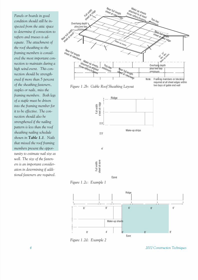
Layout
Apply structural sheathing panels with the long dimension perpendicular
to the roof framing. Start sheathing with the full 4’ width at the eaves
and ridges, so that no sheet is less than 4’ wide at the roof edge(s). All
sheathing must be attached to at least three rafters/trusses with staggered
end joints. If a row of panels must be installed that is less than four feet in
width, this make-up row should be at least 2’ wide and placed in the
middle of the roof slope. It may be necessary to have two rows of make-up
panels to accomplish this. If a make-up panel less than eight feet in
length is required within a given row, it should be placed in the middle of
a row, not at either end, but span at least three rafters. To accomplish
this, it may be necessary to use two panels, each one less than 8 feet in
length.
F u l l w
i d t h
a t h i p
M a k e u p s h e e t s
a t t a c h e d t o a t l e a s t
t h r e e r a f t e r s / t r u s s e s
T w o b a y m i n i m u m F u l l l e n g t h a t r i d g e
F u l l l e n g t h a t r i d g e
F u l l l e n g t h a t e a v e
F u l l l e n g t h a t e a v e
T w o b a y m i n i m u m
F u l l w
i d t h
a t h i p
M a k e
u p
s h e e t s
2 4 ”
2 4 ” m
i n
m i n
Figure 1.2a: Hip Roof Sheathing Layout
8/11/2019 Protect Home From High Winds
http://slidepdf.com/reader/full/protect-home-from-high-winds 9/734 2002 Construction Technique
Panels or boards in good
condition should still be in-
spected from the attic space
to determine if connection to
rafters and trusses is ad-
equate. The attachment of
the roof sheathing to the framing members is consid-
ered the most important con-
nection to maintain during a
high wind event. This con-
nection should be strength-
ened if more than 5 percent
of the sheathing fasteners,
staples or nails, miss the
framing members. Both legs
of a staple must be driven
into the framing member for
it to be effective. The con-
nection should also be
strengthened if the nailing
pattern is less than the roof
sheathing nailing schedule
shown in Table 1.1. Nails
that missed the roof framing
members present the oppor-
tunity to estimate nail size as
well. The size of the fasten-
ers is an important consider-
ation in determining if addi-
tional fasteners are required.
Figure 1.2d: Example 2
6’
8’ 4’
6’ 6’8’ 8’
6’ 8’ 8’
Ridge
Eave
Make-up sheets
Figure 1.2c: Example 1
Fullwidth
sheetatridge
Ridge
Eave
2.5’
2.5’
4’
Fullwidth
sheetateave
Make-up strips
Figure 1.2b: Gable Roof Sheathing Layout
Note: Framing members or blockingrequired at all sheet edges withtwo bays of gable end wall
M a k e u p s h e e t s
a t t a c h e d t o a t l e a s t
t h r e e r a f t e r s / t r u s s e s
N e a r f u l l l e n g t h s h e e t a t r a k e r i d g e
Overhang depthplus two bayminimum
M a k e - u p s h e e t s
T w o b a y m i n i m u m
N e a r f u l l l e n g t h s h e e t a t r a k e r i d g e
Overhang depthplus two bay
minimum
M a k e u p s h e e t s
a t t a c h e d t o a t l e a s t
t h r e e r a f t e r s / t r u s s e s
T w o b a y m i n i m u m
F u l l w
i d t h
s h e e t a
t r i d g
e
N e a r f u l l l e n g t h s h e e t a t r a k e / e a v e
N e a r f u l
l w i d t
h
s h e e t a
t e a v
e
N e a r f u l l l e n g t h s h e e t a t r a k e / e a v e
2 4 ”
2 4 ”
M i n .
M i n .
M a k e
- u p s
h e e t s
8/11/2019 Protect Home From High Winds
http://slidepdf.com/reader/full/protect-home-from-high-winds 10/732002 Construction Techniques 5
For example, a roof with a 17’ length along the slope has a make-up span
of one foot. Since the minimum allowable width for make-up sheets is 2’,
a one-foot make-up sheet cannot be used. To meet the minimum require-
ment two 2.5’ make-up rows must be used. Therefore, instead of four full
4’ wide strips and a 1’ wide make-up sheet, the roof will have 3 full 4’ wide
sheets and two 2.5’ wide make-up sheets located in the middle of the roof
See Example 1 (Figure 1.2c).
A roof with a 34’ length along the eave and 24” rafter/truss spacing has a
make-up span of two feet. Since the minimum allowable length is two
bays, a 2’ make-up sheet cannot be used. To meet the minimum require-
ment two make-up sheets must be used to span 10’. See Example 2
(Figure 1.2d).
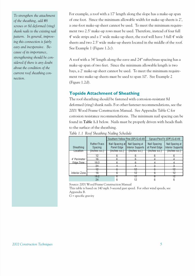
Topside Attachment of Sheathing
The roof sheathing should be fastened with corrosion-resistant 8d
deformed (ring) shank nails. For other fastener recommendations, see the
2001 Wood Frame Construction Manual. See Appendix Table C for
corrosion resistance recommendations. The minimum nail spacing can be
found in Table 1.1 below. Nails must be properly driven with heads flush
to the surface of the sheathing.
To strengthen the attachment
of the sheathing, add #8
screws or 8d deformed (ring)
shank nails to the existing nail
pattern. In general, improv-
ing this connection is fairly
easy and inexpensive. Be-cause of its importance,
strengthening should be con-
sidered if there is any doubt
about the condition of the
current roof sheathing con-
nection.
Source: 2001 Wood Frame Construction ManualThis table is based on 140 mph 3-second gust speed. For other wind speeds, see
Appendix B.G = specific gravity
Table 1.1 Roof Sheathing Nailing Schedule
Southern Yellow Pine (SP) G≥0.49 Spruce Pine Fir (SPF) G<0.49
Rafter/Truss Nail Spacing at Nail Spacing at Nail Spacing Nail Spacing atSheathing Spacing Panel Edge Interior Supports at Panel Edge Interior Supports
Location (inches o.c.) (inches o.c.) (inches o.c.) (inches o.c.) (inches o.c.)
12 6 6 6 64’ Perimeter 16 6 6 4 4Edge Zone 19.2 6 6 4 4
24 4 4 3 312 6 12 6 12
Interior Zone 16 6 12 6 1219.2 6 12 6 1224 6 12 6 6
8/11/2019 Protect Home From High Winds
http://slidepdf.com/reader/full/protect-home-from-high-winds 11/736 2002 Construction Technique
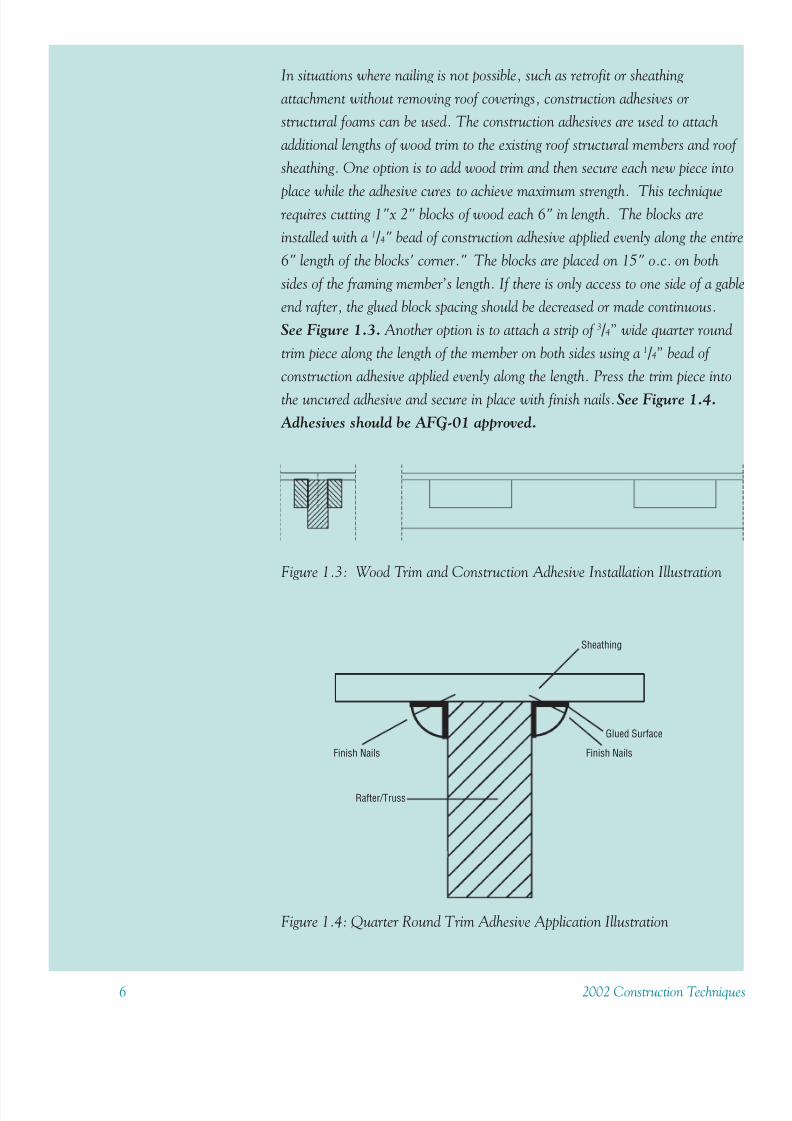
In situations where nailing is not possible, such as retrofit or sheathing
attachment without removing roof coverings, construction adhesives or
structural foams can be used. The construction adhesives are used to attach
additional lengths of wood trim to the existing roof structural members and roof
sheathing. One option is to add wood trim and then secure each new piece into
place while the adhesive cures to achieve maximum strength. This techniquerequires cutting 1"x 2" blocks of wood each 6" in length. The blocks are
installed with a 1 / 4" bead of construction adhesive applied evenly along the entire
6" length of the blocks' corner." The blocks are placed on 15" o.c. on both
sides of the framing member’s length. If there is only access to one side of a gable
end rafter, the glued block spacing should be decreased or made continuous.
See Figure 1.3. Another option is to attach a strip of 3 / 4” wide quarter round
trim piece along the length of the member on both sides using a 1 / 4” bead of
construction adhesive applied evenly along the length. Press the trim piece into
the uncured adhesive and secure in place with finish nails. See Figure 1.4.
Adhesives should be AFG-01 approved.
Figure 1.3: Wood Trim and Construction Adhesive Installation Illustration
Figure 1.4: Quarter Round Trim Adhesive Application Illustration
Sheathing
Glued Surface
Rafter/Truss
Finish NailsFinish Nails

8/11/2019 Protect Home From High Winds
http://slidepdf.com/reader/full/protect-home-from-high-winds 12/732002 Construction Techniques 7
Figure 1.5: Structural Foam Application Illustration
Sheathing
Structural FoamRafter/Truss
Underside Attachment of Sheathing
Structural foam can also be used to strengthen the sheathing-framing member
connection. The foam should be designed for structural applications. This
foam starts as a two-part solution that is sprayed from a specially designed
application machine. This allows the product to be applied in areas where it
may be difficult to reach the members. Figure 1.5 shows how the foam is
sprayed along the length of the framing member at the joint between the member
and the sheathing. The foam undergoes a catalytic reaction and begins curing
immediately. Once it has cured, it created a bond between the framing member
and the sheathing that has been tested as 2 to 4 times stronger than a
mechanically fastened connections.
Structural foam may be difficult to apply to an existing roof. Access to some
joints may be obscured.
8/11/2019 Protect Home From High Winds
http://slidepdf.com/reader/full/protect-home-from-high-winds 13/738 2002 Construction Technique
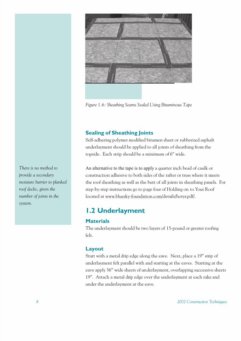
Sealing of Sheathing Joints
Self-adhering polymer modified bitumen sheet or rubberized asphalt
underlayment should be applied to all joints of sheathing from the
topside. Each strip should be a minimum of 6” wide.
An alternative to the tape is to apply a quarter inch bead of caulk or
construction adhesive to both sides of the rafter or truss where it meets
the roof sheathing as well as the butt of all joints in sheathing panels. For
step-by-step instructions go to page four of Holding on to Your Roof
located at www.bluesky-foundation.com/details/hotyr.pdf/.
1.2 Underlayment
Materials
The underlayment should be two layers of 15-pound or greater roofing
felt.
Layout
Start with a metal drip edge along the eave. Next, place a 19” strip of
underlayment felt parallel with and starting at the eaves. Starting at the
eave apply 36” wide sheets of underlayment, overlapping successive sheet
19”. Attach a metal drip edge over the underlayment at each rake and
under the underlayment at the eave.
Figure 1.6: Sheathing Seams Sealed Using Bituminous Tape
There is no method to
provide a secondary
moisture barrier to planked
roof decks, given the
number of joints in the
system.

8/11/2019 Protect Home From High Winds
http://slidepdf.com/reader/full/protect-home-from-high-winds 14/732002 Construction Techniques 9
Attachment
All underlayment should be fastened with nails and 1” diameter tags,
metal or plastic. If metal tags are used, they must be of same or similar
metal as the nails used to prevent a chemical reaction between the two
metals. These tags help to spread the fastener load to prevent the nail
heads from being ripped through the underlayment. Nails and tags should
be corrosion resistant. See Appendix Table C for corrosion resistance
recommendations. Along the overlapping rows and at the end laps, nails
should be spaced at 6” o.c. The nail spacing in the field of the
underlayment should be 12” o.c. All nail spacing is minimum spacing.
This overlap and nail pattern helps prevent the loss of the underlayment
layer in the event of the loss of the roof covering.
For added protection the first strip of underlayment can be replaced with
self-adhering polymer modified bitumen sheet no less than 3’ wide.
To improve its waterproofing capability and its adhesion to the roof deck,
hot asphalt can be mopped on the deck before the underlayment is laid in
place.
Figure 1.7: Underlayment Layout and Attachment
Metal drip edge recover underlayment
19” wide #15 asphaltfelt underlayment
#15 asphalt feltunderlayment. (typ.)
Metal drip edgerecommended under
underlayment.(typ. at eave)
Nail 12” o.c. centeredbetween side laps.
Attach underlayment atlocations with low-prohcapped-head nails or thdisks attached with rooAll nails and disks shalcorrosion resistant.
Nails 6” o.c. a2”side laps
Lap ends 4”. Offsetlaps 3” min. (typ.)
Provide 7 nails atend laps. (typ.)
Provide 4 nails atend of first course.

8/11/2019 Protect Home From High Winds
http://slidepdf.com/reader/full/protect-home-from-high-winds 15/7310 2002 Construction Technique
1.3 FlashingTo exclude water from entry in all cases where openings through roofs
have borders that are flush with or protrude beyond roof coverings, the
opening should be carefully flashed. Well-installed flashings protect the
structure from water damage. Flashing should be applied at all roof slope
changes, such as valleys and ridges. Flashing should also be applied to all
roof penetrations, such as chimneys, vents, skylights, etc., and anytime
two unlike materials come together. Flashing should be installed above
the underlayment and below the shingles.
1.4 Asphalt ShinglesThe loss of roof covering during a hurricane is extremely common. There
are several different kinds of roof coverings available on the market today
including clay, concrete, and metal tile as well as wood shake and asphalt
shingles. This document does not address many of these varied roof coverings. Contact the manufacturers for details on adapting different
roofing materials to high wind areas. Asphalt shingles, the most common
material used today, are discussed in detail. Many of the asphalt shingles
made today are tested using a constant airflow of about 60 mph. A
Category I hurricane has a minimum 1-minute sustained wind of 74 mph.
Even strong windstorms can easily exceed 60 mph wind speed. The loss
of shingles during a storm poses two problems: the house is more
vulnerable to water damage and the lost shingles become wind-borne
projectiles, which can damage property. Asphalt shingles should only be
used on roof slopes of 2/12 or greater.
Materials
Asphalt shingles should have self-seal strips. Tab adhesives are designed
for local temperature extremes, so use local products appropriate for the
climate. Standard 3-tab asphalt shingles may be used with the application
requirements discussed in the following sections. Special high wind
shingles are also available which have been tested using a constant airflowof 110 miles per hour.
Layout
Begin by attaching a starter course consisting of the top half of a shingle
with the tabs cut off. The tab-less shingle strips are installed along the
lower edge of the roof sheathing.
8/11/2019 Protect Home From High Winds
http://slidepdf.com/reader/full/protect-home-from-high-winds 16/732002 Construction Techniques 11
Go to www.bluesky-
foundation.com for info on
viewing or buying a copy of:
Holding on to Your Roof
Part I: Retrofitting Your
Roof Sheathing Using
Adhesives
Part II: Retrofitting Your
Asphalt Shingle Roof
Covering and Sheathing
Connection.
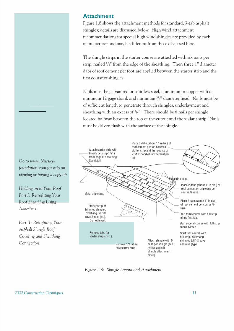
Figure 1.8: Shingle Layout and Attachment
Attach starter strip with6 nails per strip 1/2” infrom edge of sheathing.See detail.
Starter strip oftrimmed shinglesoverhang 3/8” @eave & rake (tp.).
Do not invert.
Metal drip edge.
Remove tabs forstarter strips (typ.).
Remove 1/2 tab @rake starter strip.
Attach shingle with 6nails per shingle (seetypical asphaltshingle attachmentdetail).
Start first course withfull strip. Overhangshingles 3/8” @ eaveand rake (typ).
Start second course with full stripminus 1/2 tab.
Start third course with full stripminus first tab.
Place 2 dabs (about 1” in dia.)of roof cement per course @rake.
Place 2 dabs (about 1” in dia.) oroof cement on drip edge percourse @ rake.
Metal drip edge.
Place 3 dabs (about 1” in dia.) ofroof cement per tab betweenstarter strip and first course or2”x11” band of roof cement pertab.
Attachment
Figure 1.8 shows the attachment methods for standard, 3-tab asphalt
shingles; details are discussed below. High wind attachment
recommendations for special high wind shingles are provided by each
manufacturer and may be different from those discussed here.
The shingle strips in the starter course are attached with six nails perstrip, nailed 1/2” from the edge of the sheathing. Then three 1” diameter
dabs of roof cement per foot are applied between the starter strip and the
first course of shingles.
Nails must be galvanized or stainless steel, aluminum or copper with a
minimum 12 gage shank and minimum 3/8” diameter head. Nails must be
of sufficient length to penetrate through shingles, underlayment and
sheathing with an excess of 3/4”. There should be 6 nails per shingle
located halfway between the top of the cutout and the sealant strip. Nails
must be driven flush with the surface of the shingle.
8/11/2019 Protect Home From High Winds
http://slidepdf.com/reader/full/protect-home-from-high-winds 17/7312 2002 Construction Technique
For added protection hand-tab each shingle along any roof edge with
roofing adhesive. Securing the bottom edge of each shingle will give it a
greater chance of resisting the uplift forces created by a high wind event.
Venting
Venting systems should be designed to protect from wind-driven rains.
Gable end vents should be covered to protect against wind borne debris,with an approved shutter or cover tested to the standards discussed in
Chapter 2. All vents should also be well-attached to the roof, according
to manufacturer’s recommendations to resist high winds.
8/11/2019 Protect Home From High Winds
http://slidepdf.com/reader/full/protect-home-from-high-winds 18/732002 Construction Techniques 13
Retrofit Standards for Roof
Systems_______________________________________________________________________
1. A. Replace Roof Covering and Replace
SheathingRoof covering is to be removed to the decking level and all roof deck is to
be replaced in accordance with locally adopted building codes. Nailing of
sheathing shall follow guidelines given in Option 1.B below.Prior to the
application of underlayment, it is recommended that all joints between
structural sheathing panels be taped with a self-adhering polymer modified
bitumen sheet or rubberized asphalt underlayment that has a minimum
width of 6 inches. This self-adhering product shall be applied in accordance
with the manufacturers instructions for wood application. This product
shall have adherence strength suitable so that it remains attached to the
roof deck and provides secondary water resistance if the roof cover
underlayment tears or fails in a high wind event. Roof covering shall then
be installed in accordance with locally adopted building codes. For three-
tab composite asphalt shingles, 6 roofing nails are required for each shingle.
1. B. Replace Roof Covering and Re-nail
SheathingRoof covering is to be removed to the decking level. If no sheathing
panels need replacing, all roof sheathing is to be re-nailed such that
fastener spacing complies with Table 1.1 and local building codes.
Existing fasteners may be used to satisfy this requirement. It is
recommended re-nailing be done with 8d deformed (ring) shank nails.
Prior to the application of underlayment, it is recommended that all joint
between structural sheathing panels be taped with a self-adhering polymer
modified bitumen sheet or rubberized asphalt underlayment that has aminimum width of 6 inches. This self-adhering product shall be applied in
accordance with the manufacturers instructions for wood application.
This product shall have adherence strength suitable so that it remains
attached to the roof deck and provides secondary water resistance if the
roof cover underlayment tears or fails in a high wind event. Roof covering
shall then be installed according to locally adopted building codes. For
three-tab composite asphalt shingles, 6 roofing nails are required for each
shingle.

8/11/2019 Protect Home From High Winds
http://slidepdf.com/reader/full/protect-home-from-high-winds 19/7314 2002 Construction Technique
1. C. Replace Roof CoveringRoof covering is to be removed to the decking level. Prior to
underlayment application, if no sheathing panels need replacing and
nailing pattern is sufficient, it is recommended to tape all joins between
plywood sheets with a self-adhering polymer modified bitumen sheet or
rubberized asphalt underlayment that has a minimum width of 6 inches.
This self-adhering product shall be applied in accordance with the
manufacturers instructions for wood application. This product shall have
adherence strength suitable so that it remains attached to the roof deck
and provides secondary water resistance if the roof cover underlayment
tears or fails in a high wind event. All new coverings are to be installed in
accordance with locally adopted building codes. For three-tab composite
asphalt shingles, 6 nails are required for each shingle.
1. D. Apply Adhesive to Roof Decking andRaftersFor cases where the roof covering is adequate and attic access is available,
adhesive can be applied to the underside of the roof sheathing from the
attic such that a positive bond between the joists and the sheathing is
formed. The applied adhesive shall be AFG-O1 approved. Joints between
sheathing pieces shall also be caulked with adhesive to prevent water
infiltration in the event of roof covering losses. The adhesive shall be
applied continuously to the eaves. Commercially available urethane foamsystems may also be used according to manufacturer specifications for high
wind uplift resistance.

8/11/2019 Protect Home From High Winds
http://slidepdf.com/reader/full/protect-home-from-high-winds 20/732002 Construction Techniques 15
Chapter 2
Wall Systems
8/11/2019 Protect Home From High Winds
http://slidepdf.com/reader/full/protect-home-from-high-winds 21/7316 2002 Construction Technique
Wall Systems
Building codes categorize all residential buildings as enclosed, partially
enclosed or open. These classifications are the basis for the calculation of
the external and internal pressures on the building. Most buildings are
designed and built as enclosed structures. However, perforations in the
building envelope as small as 1 percent of the wall area can transform an
enclosed building to a partially enclosed building. This doubles the uplift
pressures on the roof and the outward pressures on walls.
Unprotected windows and doors can be penetrated easily by wind borne
debris in high winds, thus allowing entry of damaging water and wind.
Protecting openings with impact resistant components can prevent muchof this damage. All wall openings should be protected since winds can
emanate from any direction in a wind event.
2.1 WindowsAll windows greater than one square foot should comply with the most
recent version of ASTM E1996, SSTD-12 or Miami-Dade County proto-
col A201, or else be protected by shutters that comply with one of those
standards.
Care should be used in the design of combination windows (several
individual windows clustered together) so that the combination window
can resist the design pressure. This can be accomplished by the window
manufacturer using “structural” mullions between the individual window
units to transfer loading to the framing around the window opening or by
installing the individual window units with structural framing in between
each window unit. The second option also has the advantage of being
able to use a number of smaller shutters to protect the window unit.
Windows located in the garage that offer access to the main structure
should be considered exterior windows and protected accordingly.

8/11/2019 Protect Home From High Winds
http://slidepdf.com/reader/full/protect-home-from-high-winds 22/732002 Construction Techniques 17
Window Selection
Each window unit must be selected to resist the maximum positive and
negative pressures listed in Table 2.1. Note that the pressure on the
window increases when the window is located closer to the edge of the
structure.
Windows are given DP Ratings based on their capability to withstandpressure. A DP Rating of 25 indicates that the window can withstand a
pressure of 25 psf, positive or negative. When selecting a window, look
for a window with a DP Rating that matches or exceeds the design pres-
sure for the window’s location.
There are two mainapproaches to retrofitting
windows to improve their
impact resistance or
completely protect them
from debris and pressure
changes.
1. Impact-resistant glass
2. Shutter systems
Window Protection
Unprotected, standard glass windows present the most vulnerable opening
in a building’s envelope. They can be broken easily by flying debris or
destroyed by wind pressure. Once window glass fails, the subsequent
pressurization of the structure can cause total destruction of the house. If
the house withstands the wind pressure, the interior may still be lost dueto water damage. With the exception of impact-resistant polycarbonate
glazing or some laminated glass systems, all window glass, whether it is
annealed, tempered, wire reinforced or insulated, needs to be protected
during a high wind event. For a typical residential application, hurricane
window film is not sufficient protection. Films can prevent injury due to
flying glass, but offer no protection once the window is breached because
they do not help keep glass in the window frame—or the frame in the
house.
Table 2.1: Window Selection Guide
Source: Table based on the wind provisions in ASCE 7-98.
Window is considered to be in edge strip if any portion of window is located within 4' of edge of structure. This table is based on 140 mph 3-second gust wind speed and
Exposure B. For values for different wind speeds, see Appendix D.
Greater Than 30 feet andMean Roof Less Than or Equal to Less Than or Equal to
Height 30 feet 45 feet
All Interior Edge All Interior Edge
Zone Zones Zone Strip Zones Zone Strip
Design Pressure (psf)
Size of Door orWindow (sq ft) Pos (+) Neg (-) Neg (-) Pos (+) Neg (-) Neg (-)
0-25 45 -48 -54 50 -53 -60
25-50 43 -46 -51 48 -52 -5550-100 40 -43 -48 45 -51 -53
100-200 39 -43 -45 43 -48 -50200+ 39 -42 -41 43 -47 -48

8/11/2019 Protect Home From High Winds
http://slidepdf.com/reader/full/protect-home-from-high-winds 23/73

8/11/2019 Protect Home From High Winds
http://slidepdf.com/reader/full/protect-home-from-high-winds 24/732002 Construction Techniques 19
during a storm. For example, if the shutters will cover windows on an
upper floor or in a hard-to-reach position, they should be operable from
the inside. Temporary shutters can be difficult and/or dangerous to install
on second floor windows or higher because they require the use of a ladder.
Permanent Shutters
Permanent shutters should be installed by trained individuals according tothe manufacturer’s specifications to ensure the shutters perform as de-
signed and tested. The most important factor to consider when choosing
a shutter system is its installation as an approved system. It should be
designed and tested for resistance to hurricane force wind loads and debris
impact. Shutters should be able to withstand both positive and negative
wind pressures.
Permanent shutters come in many types and styles, including Bahama,
rolling, accordion, and colonial. Location of the building, location of the
window, and cost are some of the factors to consider when choosing a
shutter style. Depending on the manufacturer, each of these shutter
systems may either close from the inside or the outside.
Many shutters on the market may NOT be designed for high winds and
the associated impacts. It is important to look for shutters that have been
designed and tested to high wind standards. All permanent shutters
should comply with the most recent version of ASTM E1996, SSTD-12 or Miami-Dade County protocol A201.
Bahama Shutters
Bahama shutters are attached directly
above the window with a top hinge.
Adjustable side arms allow the shutter
to be raised or lowered. When closed
at the bottom and latched, approved
shutters provide the necessary wind
and impact resistance. Bahama
shutters should be installed accord-
ing to manufacturer’s specifications.
Bahama shutters should not be used
for windows that open outwards.
Figure 2.2: Bahama Shutter
8/11/2019 Protect Home From High Winds
http://slidepdf.com/reader/full/protect-home-from-high-winds 25/7320 2002 Construction Technique
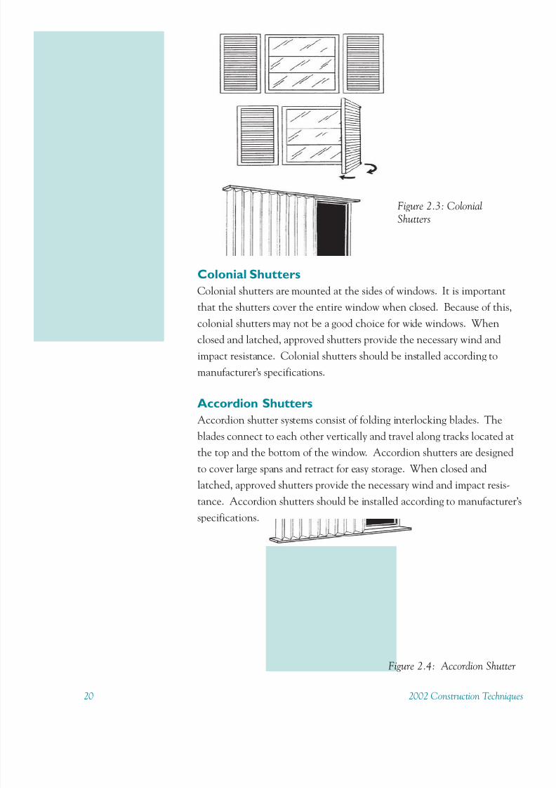
Colonial ShuttersColonial shutters are mounted at the sides of windows. It is important
that the shutters cover the entire window when closed. Because of this,
colonial shutters may not be a good choice for wide windows. When
closed and latched, approved shutters provide the necessary wind and
impact resistance. Colonial shutters should be installed according to
manufacturer’s specifications.
Accordion Shutters
Accordion shutter systems consist of folding interlocking blades. The
blades connect to each other vertically and travel along tracks located at
the top and the bottom of the window. Accordion shutters are designed
to cover large spans and retract for easy storage. When closed and
latched, approved shutters provide the necessary wind and impact resis-
tance. Accordion shutters should be installed according to manufacturer’s
specifications.
Figure 2.3: ColonialShutters
Figure 2.4: Accordion Shutter

8/11/2019 Protect Home From High Winds
http://slidepdf.com/reader/full/protect-home-from-high-winds 26/732002 Construction Techniques 21
Rolling Shutters
Rolling shutters consist of slats that glide up
and down on tracks at the side of each
window. When closed and latched, approved
shutters provide the necessary wind and
impact resistance. Rolling shutters should be
installed according to manufacturer’s specifi-cations.
Temporary Shutters
Temporary shutters can be put in place by the
owner in the event of a storm warning.
Shutters should be able to withstand both
positive and negative wind pressures. Ply-
wood shutters and storm panels are two
examples of temporary shutters.
Plywood Shutters
One of the least expensive solutions for protecting windows is to con-
struct plywood panels that can be installed when a storm warning is
issued. Although the plywood may not withstand as much impact as
other shutter options, they do minimize the size of the opening into the
home. The attachment of plywood shutters depends on the structural
framing material and the exterior finish of the house. The mountinghardware should be pre-installed around each window and each panel
should be labeled with its intended location to facilitate installation.
While plywood shutters offer the lowest cost protection, they are cumber-
some to store and carry. Often more than one person is required to install
them. The Engineered Wood Association (APA) has developed standard
designs of plywood shutters for masonry and wood construction. For some
spans, 2x4s may be needed to strengthen the panels. The recommenda-
tions of the APA should be followed to determine the thickness of the
plywood panels. FEMA has also developed several details for installation
of plywood shutters on wood frame as well as masonry walls. FEMA or
APA publications can be used for design and construction of plywood
shutters. Both of these organizations maintain web sites at www.fema.gov
and www.apawood.org, respectively.
Figure 2.5: Rolling Shutter

8/11/2019 Protect Home From High Winds
http://slidepdf.com/reader/full/protect-home-from-high-winds 27/7322 2002 Construction Technique
With many doors it may
be difficult to determine
the frame installation. If
possible, pry up a length of
door molding. If there is
concern or doubt about
the frame’s installation,
add screws around the
frame that are long enough
to penetrate to the framing members.
Hardware is another area
that can be retrofitted to
improve a door’s strength.
Storm Panels
In addition to plywood, other temporary shutter systems are available,
including steel and aluminum panels and clear polycarbonate panels. The
advantage that these systems have over plywood is that they are designed
specifically to withstand the impact forces of a high wind event. Usually
these panels are corrugated and come in standard widths, allowing them
to be joined together to cover wider openings. As with permanent shut-ters, the panel systems should be tested and rated by the strictest current
testing procedures.
Storm panels also may have an installation system that is quicker than
attaching plywood panels. Clear panels can be installed well in advance
of the storm’s approach and allow light to continue to come through the
windows while other preparations inside the house are being made.
In general, the same principles for the plywood systems apply to other
temporary panel products. They should meet the specific standards for
impact resistance, their mounting hardware should be installed well
before a storm’s impact and they should be labeled for each respective
opening.
2.2 Exterior DoorsThree items should be considered when installing doors: the door, the
frame and the hardware. All three items are important in maintaining
the strength of the entire door system. Failure of any one of these three
components would result in a breach of the building envelope and ensu-
ing damage to the residence.
Exterior doors must be strong enough to resist the wind loads and impact
loads of wind- borne debris or be protected with a panel or shutter system
Doors that open outward do not have the additional resistance to wind
suction provided by the doorjamb that inward opening doors have. Also,
hollow wood doors can fail under the wind and impact loads in a high
wind event. A secure lock set is also needed to help the door resist debris
impact.
Doors located in the garage that offer access to the main structure should
be considered exterior doors and protected accordingly.

8/11/2019 Protect Home From High Winds
http://slidepdf.com/reader/full/protect-home-from-high-winds 28/732002 Construction Techniques 23
Frames
The frames of all exterior doors must be mounted securely to the wall
systems. Additional fasteners can be added to strengthen frames as
needed. Frames that are attached improperly could fail in a hurricane and
allow wind and water penetration.
HardwareEvery door should have three four-inch screw hinges and a dead bolt
security lock with a minimum one inch bolt throw length. Screws used
for the hinges and the strike plate should extend into the framing
members, not just into the door frame. This is true for the dead bolt too.
The bolt throw should be long enough to extend to the framing members
not just into the door frame, which could split and fail in a storm.
The screws included with pre-hung doors should be replaced with screws
of sufficient length to extend into the framing members.
Double doors should have either surface or integral bolts installed that
secure the center of the doors to the header framing member and extend
into the subfloor. See Figure 2.6 below.
Figure 2.6: Door Hardware Illustration
The screw lengths and deadbolt throw should have been
measured during the house
inspection. If either item is
too short to extend through
the frame, they should be
replaced. Screws for the
hinges and strike plates can
be removed and replaced
with longer screws. The
dead bolt also can be
removed from the door and
replaced with a new dead
bolt with a longer throw.
The hole in the door frame
may have to be extended to
accommodate the longer
throw length.
These are small retrofits that
can increase the door’s
strength to withstand a
storm and any other
unwanted attempts to gain
entry to the home.
Retrofitting can be
completed by checking the
length of the bolts, replacing
them if necessary, and
extending the hole depth
through the door frame and/
or threshold.
8/11/2019 Protect Home From High Winds
http://slidepdf.com/reader/full/protect-home-from-high-winds 29/7324 2002 Construction Technique
To ensure that the frame is
fully installed, all mounting
holes should be used and the
condition of the original
fasteners should be checked.
If any mounting holes are
not used or if any of the
screws have deteriorated,
new screws should be
installed.
If the sliding glass doors are
protected by a shutter or a
panel, adding fasteners to
the frame may not benecessary.
Glass Doors
Glass doors should be protected by one of the systems discussed in the
Windows section. In addition, sliding doors should be mounted securely
in their frames so they cannot be pushed in or pulled out under high wind
loads. The frame itself should be attached securely to the wall so that it,
too, does not fail under load.
2.3 Garage DoorsGarage doors serve as additional points of failure and subsequent breaches
of the house envelope. Garage doors are vulnerable to high wind loads fo
two reasons - the relatively long span of opening that they cover and the
strength of the materials from which their systems are constructed. Many
garage doors are constructed from lightweight materials to reduce weight
and expense. Although their lighter weight makes them easier to raise
and lower, it also makes them less resistant to the wind and impact forces
of a hurricane.
Garage door assemblies have three major weaknesses:
1. Deflection under wind loads
2. Track strength and installation
3. Impact resistance
Unbraced garage doors can deflect under the loads applied by high winds.
Depending on whether the door is on the windward or leeward side of the
structure, it will experience positive or negative pressures, respectively.
These pressures will push and pull the door out of its track. If the door is
not braced to resist these deflections, it may fail and allow the pressuriza-
tion of the residence’s interior.
The track is the second system that can fail under a storm’s forces. A
lightweight or poorly anchored and braced track may torque and twist
from the wind force on the garage door. As the track is bent out of shape
and fails, the door glider wheels will pull out of the track and the door wil
collapse.
The last concern when addressing garage doors is impact resistance.
Many doors are not designed to withstand the impact of wind borne
debris created by a hurricane. If the garage door is perforated during a
storm, it may allow interior pressurization and water damage.

8/11/2019 Protect Home From High Winds
http://slidepdf.com/reader/full/protect-home-from-high-winds 30/732002 Construction Techniques 25
Choosing a Garage Door
Use a garage door that is designed specifically to withstand both the wind
load and impact forces of a high wind event. Garage door and tracks
should comply with the most recent version of ASTM E1996, SSTD-12
or Miami-Dade County protocol A201. Garage doors must be properly
installed to provide protection.
Protect The Opening
For additional protection, construct and install a protective panel system
that covers the garage door opening in the same manner that a shutter
covers a window. The construction of a garage shutter is identical to the
construction and installation for a window, however, the extra span needs
to be considered and supported as if it were a large window.
Brace The Garage Door
There are two options for bracing the garage door.
The first option is to attach horizontal wood or metal girts to the interior
surface. The bracing members should extend the length of the door. The
girts are attached to the vertical bracing of the garage door. This option
allows the garage door to remain functional and, therefore, constantly
braced.
The second option is to attach vertical wood or metal girts to the interior
Figure 2.7: Garage Door Bracing IllustrationCourtesy of American Red Cross and Federal Emergency Management Agency -
Against The Wind.

8/11/2019 Protect Home From High Winds
http://slidepdf.com/reader/full/protect-home-from-high-winds 31/7326 2002 Construction Technique
surface. The bracing members should start above the garage door and
continue down the door and into pre-drilled holes in the garage floor.
The girts are attached to the vertical bracing of the garage door. This
option renders the garage door inoperable and, therefore, bracing should
be put in place by the owner in the event of a storm warning.
Brace The FrameSeveral steps are required to strengthen and brace the garage door frame.
The first element to be considered is the track itself. The heavier the
gauge of the material from which the frame is constructed, the better. A
track with a greater cross-sectional area will resist twisting more than a
thinner track. A second strengthening element is a web brace on the
brackets that connect the track to the wall. Web braces can be welded to
these brackets or the brackets can be removed and replaced with brackets
that have integral web bracing. The last connection to be considered to
strengthen the frame is the attachment of the frame to the garage wall. If
the garage door opening is masonry or concrete, the brackets should be
installed with expansion anchors to resist pullout. An epoxy adhesive can
be used in addition to the expansion anchors to provide even greater
resistance. If the house is wood framed, the brackets should be attached
to the framing, not just to the interior surface material. In either case, the
bolts or screws should be sized according to the manufacturer’s recommen-
dations for the specific length and width of the garage door.
Connectors
Connectors are available from a variety of connector manufacturers and
there are a many types that can be used in different situations. Some of
the applications in this chapter may include the use of a variety of con-
nectors and anchor bolts. All connectors and anchor bolts shall be
installed in accordance with the manufacturers specifications and in
compliance with the locally adopted minimum building code. All connec
tors should be corrosion-resistant. See Table C in the Appendix for
recommendations.
Several retrofit optionsaddress these weaknesses:
1. Replace the garage door
system
2. Protect the opening
3. Brace the door
4. Brace the frame
The track thickness can
only be increased by
replacing the track.

8/11/2019 Protect Home From High Winds
http://slidepdf.com/reader/full/protect-home-from-high-winds 32/732002 Construction Techniques 27
Retrofit Standards for Wall
Systems_______________________________________________________________________
2. A. Install Code Compliant Shutters on
WindowsShutters must satisfy the impact resistance and pressure standards in
SSTD 12-97 of the Standard Building Code, ASTM E1886 and ASTM
E1996 or standards in the Miami-Dade Protocol A201. Shutters must be
installed as per the manufacturers specifications. Other requirements: If the
structure is equipped with shutter protection or the equivalent thereof, non-
compliance with the one of the above reference standards should be verified
before replacement with new products. The contractor will ensure that all local
codes, standards and requirements are met.
2. B. Replace Windows with Code
Compliant Impact Resistant ProductsExisting windows shall be replaced with units that satisfy the impact
resistance and pressure standards in SSTD 12-97 of the Standard Building
Code, ASTM E1886 and ASTM E1996 or standards in the Miami-Dade
Protocol A201. Windows must be installed as per the manufacturers
specifications. Other requirements: The contractor will ensure that all localcodes, standards and requirements are met.
2. C. Install Code Compliant Accordion
Storm Shutters on Sliding Glass DoorsProtection devices must meet impact resistance and pressure standards in
SSTD 12-97 of the Standard Building Code, ASTM E1886 and ASTM
E1996 or standards in the Miami-Dade Protocol A201. All devices must
be installed according to the manufacturers instructions. Other require-ments: See other requirements for Retrofit 2.B. above.

8/11/2019 Protect Home From High Winds
http://slidepdf.com/reader/full/protect-home-from-high-winds 33/7328 2002 Construction Technique
2. D. Replace Sliding Glass Doors with
Code Compliant Impact Resistant
ProductsExisting sliding glass doors shall be replaced with units that meet impact
resistance and pressure standards in SSTD 12-97 of the Standard Building
Code, ASTM E1886 and ASTM E1996 or standards in the Miami-Dade
Protocol A201 for both impact resistance and pressure requirements.
Sliding glass doors must be installed as per the manufacturers specifica-
tions. Other requirements: See other requirements for Retrofit 2.B. above.
2. E. Replace Garage Doors with Code
Compliant Impact Resistant ProductsProtection devices must meet impact resistance and pressure standards in
SSTD 12-97 of the Standard Building Code, ASTM E1886 and ASTM
E1996 or standards in the Miami-Dade Protocol A201. All devices must
be installed according to the manufacturers instructions. Other require-
ments: See other requirements for Retrofit 2.B. above.
2. F. Reinforce Garage DoorsRetrofit existing garage door with a “post” system that can be locked
during severe storms and provides positive reinforcement against pressure
loads. Brace the garage door frame. Materials and methods used to
reinforce garage doors and frame shall be installed per the manufacturers
specifications and in compliance with the locally adopted minimum
building code.
2. G. Replace One Entry Door and Shutter
Remaining DoorsOne entry door shall be replaced with an impact resistant product meet-
ing impact resistance and pressure standards in SSTD 12-97 of the Stan-
dard Building Code, ASTM E1886 and ASTM E1996 or standards in the
Miami-Dade Protocol A201. All remaining entry doors shall be equipped
with code compliant shutter devices. All devices must be installed accord
ing to the manufacturers instructions. Other requirements: See other re-
quirements for Retrofit 2.B. above.

8/11/2019 Protect Home From High Winds
http://slidepdf.com/reader/full/protect-home-from-high-winds 34/732002 Construction Techniques 29
2. H. Replace all Entry Doors with Code
Compliant Impact Resistant ProductsExisting entry doors shall be replaced with units that meet impact resis-
tance and pressure standards in SSTD 12-97 of the Standard Building
Code, ASTM E1886 and ASTM E1996 or standards in the Miami-Dade
Protocol A201. Entry doors must be installed as per the manufacturers
specifications. Other requirements: See other requirements for Retrofit 2.E.
above.

8/11/2019 Protect Home From High Winds
http://slidepdf.com/reader/full/protect-home-from-high-winds 35/7330 2002 Construction Technique
This page intentionally left blank.

8/11/2019 Protect Home From High Winds
http://slidepdf.com/reader/full/protect-home-from-high-winds 36/732002 Construction Techniques 31
Chapter 3
Light Framing

8/11/2019 Protect Home From High Winds
http://slidepdf.com/reader/full/protect-home-from-high-winds 37/7332 2002 Construction Technique
Light Framing
3.1 Roof Framing
The two most common roof styles are gable and hip. Gable roofs areusually easier and cheaper to construct than hip roofs. Hip roofs, how-
ever, do have an advantage. The area of highest pressure on a hip roof is
half that of a gable roof. This is because a hip roof is more aerodynamic.
A hip roof also provides diaphragm support at the top of the end wall,
making it much stronger than a gable end wall which has no lateral
support at the junction of the top of the end wall and the bottom of the
gable truss. This is a very weak condition as customarily built (platform
framing) and special provisions must be made for support or continuous
framing at that point.
Light-framed roofs may be rafter-joist or truss. The following recommen-
dations or roof systems include roofs for the main structures, porches and
other built-out rooms. The following recommendations for roof systems
include roofs for the main structures, porches and other built-out rooms.
Rafter-Joist
The maximum rafter spacing, for a rafter-joist roof, should be 24” o.c.
The end of each rafter or ceiling joist should have at least 1.5” of bearing
on wood or metal.
A ridge board or a ridge beam is required for connection of rafters to each
other at the roof ridge.
Figure 3.1 Gable Roof Figure 3.2 Hip Roof

8/11/2019 Protect Home From High Winds
http://slidepdf.com/reader/full/protect-home-from-high-winds 38/732002 Construction Techniques 33
For a roof slope of less than 3/12 (25%), a ridge beam should be used.
The ridge beam should be designed for the specific span and load of the
roof that is to be supported by the ridge beam. If the span is long, the
ridge beam can be designed to transfer load to intermediate columns
along its length. Figures 3.3a and 3.3b show two ways of connecting
rafters to the ridge beam.
Ridge boards should carry no load other than bearing. Ridge boards
should be a minimum 2” nominal thickness and no less in depth than the
depth cut of the rafter. Rafters should be placed directly opposite eachother and bear against the ridge board. Either ceiling joists or rafter ties
should be used with a ridge board and should be parallel to rafters. Ceil-
ing joists or rafter ties should be continuous or securely connected where
they meet over interior partitions and nailed to adjacent rafters to provide
a continuous tie across the building. In addition to the ceiling joists or
rafter ties, a 1”x 6” collar beam should be nailed in the upper third of the
roof to every third pair of rafters. If ceiling joists are not an option, such
as with cathedral ceilings, collar beams should be nailed in the upper
Figure 3.3a Rafter to Ridge Beam Bearing Connection
Figure 3.3b Rafter to Ridge Beam Hanger Connection

8/11/2019 Protect Home From High Winds
http://slidepdf.com/reader/full/protect-home-from-high-winds 39/7334 2002 Construction Technique
third of the roof to every pair of rafters. Metal straps are also available for
collar ties, and leave more head room on low-slope roofs.
Uplift connectors should be provided at rafter bearing to resist the uplift
loads in Table 3.1. Uplift connection may be from rafter to plate or from
rafter to stud. When the former method is used there should also be
adequate connection between the plate and the stud. Figure 3.6 illus-
trates the rafter to plate to stud connections for wood framing. Framinganchors designed to carry horizontal load may be substituted for toe nails.
If metal studs are used, substitute screws for nails as described in manufac-
tures instructions. In addition to uplift loads connections should be
capable of resisting 150 lbs of lateral load parallel and perpendicular to
the wall for roof members spaced 12” o.c., 200 lbs for roof members spaced
16” o.c., and 300 lbs for roof members spaced 24” o.c.
Figure 3.4 Ceiling Joist Detail
Figure 3.5 Rafter Tie Detail
Metal strapping used as collar
ties may be an excellent
option for retrofitting the roof
framing.

8/11/2019 Protect Home From High Winds
http://slidepdf.com/reader/full/protect-home-from-high-winds 40/73

8/11/2019 Protect Home From High Winds
http://slidepdf.com/reader/full/protect-home-from-high-winds 41/7336 2002 Construction Technique
Figure 3.8 Valley Framing
Valley and Hip Framing
All valleys and hips should have rafters no less than two inches nominal
thickness and no less than the cut end of the rafter in depth. The hip and
valley rafters should be designed to carry and distribute the specific load a
that point or be supported at the ridge by a brace to a bearing partition.
Figure 3.7 Hip Framing

8/11/2019 Protect Home From High Winds
http://slidepdf.com/reader/full/protect-home-from-high-winds 42/732002 Construction Techniques 37
Trusses
The maximum spacing for a truss roof should be 24” o.c. Trusses should
be braced to prevent out-of-plane rotation and provide lateral stability.
Trusses should not be notched, drilled, cut, spliced, or otherwise altered in
any manner without approval of the truss designer.
Uplift connectors should be provided at truss bearing to resist the upliftloads in Table 3.1. Uplift connections can be from truss to plate or truss to
stud. Figure 3.9 illustrates the truss to plate to stud connections for wooden
framing. If metal studs are used substitute screws for nails as described in
manufactures instructions. In addition to uplift loads connections should be
capable of resisting 150 lbs of lateral load parallel and perpendicular to the
wall for roof members spaced 12” o.c., 200 lbs for roof members spaced 16”
o.c., and 300 lbs for roof members spaced 24” o.c.
Valley and Hip Roofing
Where trusses are used to form a hip roof, a step-down hip system should
be used as shown in Figure 3.10. Uplift connections at bearing of hip
trusses should be determined using Table 3.2. This method is for a step-
down hip system only.
Figure 3.9 Various Truss toPlate, Truss to Stud, and
Plate to Stud Connections

8/11/2019 Protect Home From High Winds
http://slidepdf.com/reader/full/protect-home-from-high-winds 43/7338 2002 Construction Technique
Hip Truss From Table 3.1- 7' Endjack 11' EndjackMember Find Uplift System System
Load for: Multiply Uplift Load By
Endjacks 24' Building Width 0.68 0.68
Cornerjacks 24' Building Width 0.75 0.85
Hipjack 24' Building Width 1 1.1
with Trusses @ 24" o.c.
#1 Hip Truss Actual Building Width 1.8 2
with Trusses @ 24" o.c.
Source: 1999 SBCCI.
Table 3.2 Uplift Loads at Bearing for Step-Down Hip
Roof Systems
Figure 3.10 Hip Roof Framing with Trusses
8/11/2019 Protect Home From High Winds
http://slidepdf.com/reader/full/protect-home-from-high-winds 44/732002 Construction Techniques 39
Double Header Double
TrimmerRafter
Rafter
Double Header
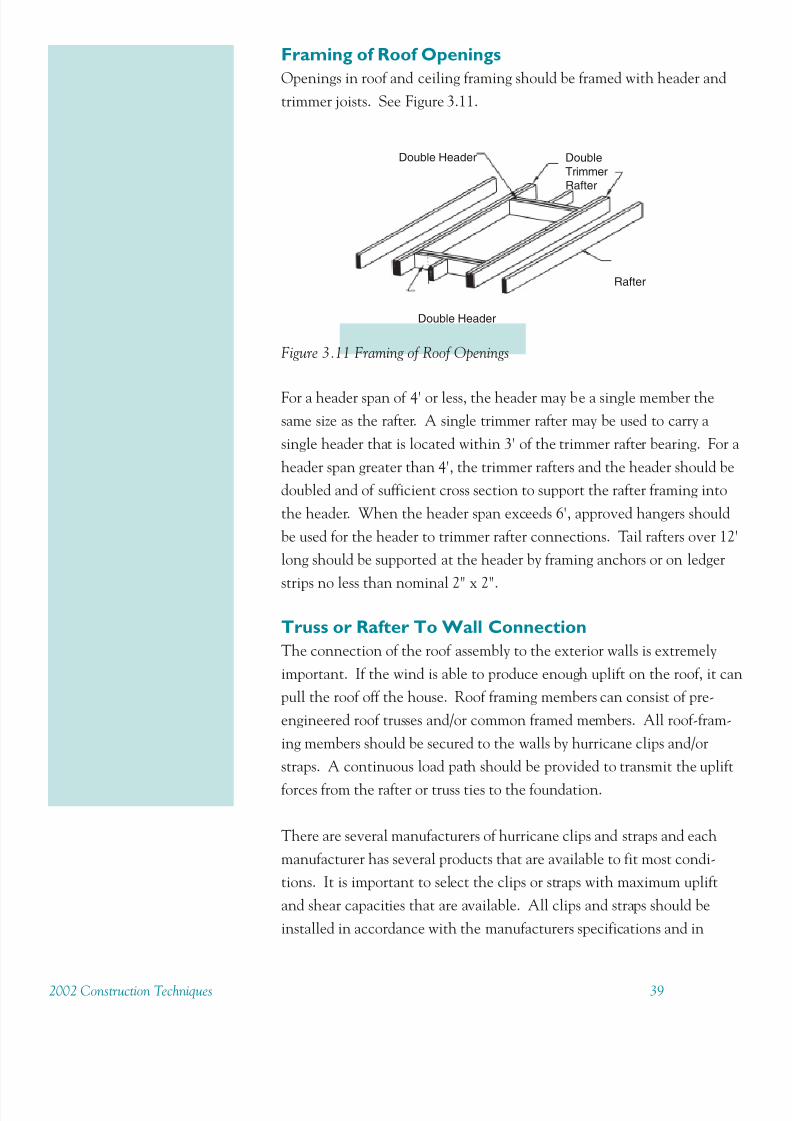
Framing of Roof Openings
Openings in roof and ceiling framing should be framed with header and
trimmer joists. See Figure 3.11.
Figure 3.11 Framing of Roof Openings
For a header span of 4' or less, the header may be a single member the
same size as the rafter. A single trimmer rafter may be used to carry a
single header that is located within 3' of the trimmer rafter bearing. For a
header span greater than 4', the trimmer rafters and the header should be
doubled and of sufficient cross section to support the rafter framing into
the header. When the header span exceeds 6', approved hangers should
be used for the header to trimmer rafter connections. Tail rafters over 12'
long should be supported at the header by framing anchors or on ledger
strips no less than nominal 2" x 2".
Truss or Rafter To Wall Connection
The connection of the roof assembly to the exterior walls is extremely
important. If the wind is able to produce enough uplift on the roof, it can
pull the roof off the house. Roof framing members can consist of pre-
engineered roof trusses and/or common framed members. All roof-fram-
ing members should be secured to the walls by hurricane clips and/or
straps. A continuous load path should be provided to transmit the uplift
forces from the rafter or truss ties to the foundation.
There are several manufacturers of hurricane clips and straps and each
manufacturer has several products that are available to fit most condi-
tions. It is important to select the clips or straps with maximum uplift
and shear capacities that are available. All clips and straps should be
installed in accordance with the manufacturers specifications and in
8/11/2019 Protect Home From High Winds
http://slidepdf.com/reader/full/protect-home-from-high-winds 45/7340 2002 Construction Technique
The intersection of the top of the wall and the roof are covered on the interior of
the building by the wall finish and on the exterior by the soffit assembly. This
makes retrofitting the roof-to-wall connection difficult. There are three
approaches to gain access to add hurricane straps to the roof/wall intersection.
Potentially several different products can be used. Each manufacturer can offer
technical information on uplift load resistance and recommend which products
are suitable for retrofit. For retrofitting in tight areas, screws may be used in place of nails, according to strap manufacturer’s instructions. Short nails made
for connectors are easier to install when retrofitting and help prevent bent nails
in connectors.
Retrofit Techniques and Products - Clips and Straps
There are three possible ways to gain access to the intersection of the roof to the
wall: from the interior, from the exterior, and during re-roofing.
From The InteriorOne solution is to remove the covering materials around the top of the interior
walls and ceiling. This process will provide access to the trusses and the top
plate of the wall. The expense of this technique is depends on the type of interior
finish. Some interior finishes such as plaster or wall papered walls may be too
expensive, invasive and time consuming to consider making holes in these walls
and then repairing after the retrofit is complete. If the interior is wood panels or
drywall, however, it may be more economical to remove these materials to gain
access to the top of the wall, install the retrofit and repair the access point.
From The Exterior
Access to roof members and top of the wall also may be gained from the
exterior. An examination of the soffit and exterior cladding must be made to
determine the cost, invasiveness and time to complete the retrofit. It may be as
simple as removing the soffit material to gain access, make the retrofit and
replace the soffit. In other cases, some access points may have to be cut through
cladding or cladding material may have to be removed and replaced once the
retrofit is accomplished.
During Re-Roof
When the sheathing is removed there is greater access to all components of the
roof load path. It also is easier to install a greater variety of clips or straps than
what the limited access of the attic or soffit may allow. This greater access offers
an opportunity to examine the condition of any existing connectors that may be
present. If any of these components appear corroded, damaged or incorrectly
installed, they should be replaced at this time.

8/11/2019 Protect Home From High Winds
http://slidepdf.com/reader/full/protect-home-from-high-winds 46/732002 Construction Techniques 41
compliance with the locally adopted minimum building code. See Figure
3.9 for some examples of clips and straps.
Gable End Bracing
Another major failure point is the collapse of the gable end. If gable-end
framing has not been sufficiently braced during construction it can deflect
and possibly fail under the strong inward and outward pressures thathurricane winds induce on a house. The collapse a gable end allows
internal pressurization. Wind and water damage may occur once the
building envelope has been breached. Figure 3.12 shows detail on bracing
a gable end wall.
Installing Bracing at Bottom of the Gable End
The forces produced by a hurricane on the gable ends can push or pull
until the deflection causes failure. Bracing the bottom of the truss to the
interior framing members gives the gable end increased strength to resist
the inward and outward forces that the winds apply.
To brace the bottom of the gable end, 2x4 members with a minimum
length of 8’ are installed perpendicular to the plane of the gable end at 6'
o.c. These bracing members should be connected to the bottom chord of
the gable end or to the base of the studs of the gable end with metal
connectors and fastened to each of the interior framing members they
intersect - either the bottom chords of the interior trusses or other fram-ing members. These connections should be made with a minimum of two
16d nails at each intersection.
Retrofit Techniques
and Products - Gable
End BracingThree retrofits have been
designed to prevent gable
end failure:
1. Installing bracing at
the bottom of the gable
end
2. Installing bracing
along the top edge of
the gable end
3. Strengthening the
connection between the
bottom of the gable end
and the top of the
sidewall
Bracing at the bottom of
the gable end is a retrofitthat provides effective
protection against
collapse. The top of the
gable end is braced by the
sheathing, assuming that it
is well connected, but the
bottom of the gable end
may be unbraced. This
lack of bracing would
make it quite vulnerable to
failure.
Figure 3.12 Roof Sheathing Layout and Endwall Bracing.
Rafter/Truss
Building Length
Sheathing
Blocking @
48” o.c. max.in first two
framingspaces at
each end

8/11/2019 Protect Home From High Winds
http://slidepdf.com/reader/full/protect-home-from-high-winds 47/7342 2002 Construction Technique
Installing Bracing Along the Top Edge of the
Gable End
Bracing at the top of the gable end can be achieved in two ways. One
method is to use the same technique as above. That is, installing 8' long
2x4 members at 6' o.c. perpendicular to the gable end surface.
Another method is to install 2x4 blocking at 24" o.c. between the gableend framing and first two interior rafters or truss top chords. The concept
behind this more limited approach is that the roof sheathing will provide
most of the support and connection along the top of the gable end and
the two layers of blocking will reinforce this support.
Connecting the Bottom of the Gable End to the Top
of the End Wall
The bottom chord of the gable-end truss should be attached securely to
the top plate below it; there should be no visible gaps. A pair of nails, a
minimum of 10d for wood framing, should be toenailed on each side 24"
o.c. to create a solid connection between the truss and the top plate. For
metal framing replace the 10d nails with #8 screws. This connection will
reduce the deflection and possibility of failure of the gable end wall during
a hurricane.
Lookout Gable End Overhangs
It is a common building practice to construct the framing for the over-hang at a gable end on the ground and to tack it in place at the roof
eaves. This overhang commonly is referred to as ladder framed because
the framing looks like a ladder before it is attached to the house (see Figure
3.13). Although, this is an economical method of constructing an over-
hang, it is a poor design in terms of wind resistance. The attachment of
the ladder frame to the house is weak. It is designed to resist the gravity
loads that it constantly experiences, but it is not designed to resist the
uplift forces of a hurricane. Hurricane-force winds can push up the
overhangs and pry the sheathing loose along the edge. Once the sheath-
ing along the edge is gone, the entire roof is at risk.
One solution to this problem is to add new lookouts to create the over-
hang using 2x6 members (see Figure 3.14). The new 2x6 members are
placed at 2’ o.c. with the 6” face parallel to the sheathing surface. They
extend from the second framing member, across the gable end member,
and project out the distance of the overhang. To maintain the level of
The last important area to
retrofit at the gable ends is
the connection between the
gable- end trusses and the
top plate of the end wall
below. This is a quick and
easy retrofit that requiresonly a hammer and nails.
This connection also can be
made using hurricane clips
or straps to secure the truss
to the wall top plate. Clips
or straps can be used on
both masonry and wood
frame construction. Check
with the manufacturer of
the chosen connector to
recommend the appropriate
product and installation
methods.

8/11/2019 Protect Home From High Winds
http://slidepdf.com/reader/full/protect-home-from-high-winds 48/732002 Construction Techniques 43
the roof, the roof framing members must be notched to accept the lookou
members. Since most building codes forbid cutting into the depth of a
framing member in the middle third of its span, a 2x4 should be attached
to the second rafter or the truss. This additional 2x4 is attached only to
the second roof framing element.
Connectors
Connectors are available from a variety of connector manufacturers and
there are a many types that can be used in different situations. Some of
the applications in this chapter may include the use of a variety of con-
nectors and anchor bolts. All connectors and anchor bolts should be
installed in accordance with the manufacturers specifications and in
compliance with the locally adopted minimum building code. All con-
nectors should be corrosion-resistant. See Table C in the Appendix for
recommendations.
During re-roofing, the
sheathing along the gable
edge can be removed and
2x6 members can be
retrofitted to create the
overhang.
Figure 3.13 Ladder Framing for Overhang
Lookout Block
Gable End Truss or Endwall
Section A-A

8/11/2019 Protect Home From High Winds
http://slidepdf.com/reader/full/protect-home-from-high-winds 49/7344 2002 Construction Technique
Lesser ofL/2 or 2’
RequiredBlocking
Minimum 2x4 Outlooker
Gable Endwall
Section A-A
Figure 3.14 Lookout Framing for Overhang
3.2 Wall FramingWall studs should be continuous between horizontal supports (floor,
ceiling or roof diaphragms). If platform construction is used on a gable
endwall, the ceiling diaphragm must have adequate strength and stiffness
to brace the gable endwall against out-of-plane loads at the platform level
If there is not a ceiling diaphragm (cathedral ceiling or open floor plan
with two-story walls), balloon framing should be used with the wall studs
spanning the full height of the walls.
Studs should be selected in accordance with Table 3.3. Studs should be
continuous between horizontal supports. A minimum of three studs
should be provided at each corner in an exterior wall.

8/11/2019 Protect Home From High Winds
http://slidepdf.com/reader/full/protect-home-from-high-winds 50/732002 Construction Techniques 45
Table 3.3 Stud Selection
Nominal Stud Sizes
2 x 4 2 x 6 2 x 8
Stud Length Stud Spacing(ft) (in)
12 1312 531 306
8 16 1749 708 408
24 2623 1062 611
12 1982 803 462
10 16 2643 1070 616
24 3965 1605 924
12 2767 1120 645
12 16 3689 1494 86024 5533 2241 1290
12 3658 1481 852
14 16 4877 1975 1137
24 — 2962 1705
12 4650 1883 1084
16 16 — 2511 1445
24 — 3766 2167
12 5737 2323 1337
18 16 — 3098 178324 — 4647 2674
12 — 2801 1612
20 16 — 3735 2149
24 — 5602 3224
Source: 2001 Wood Frame Construction Manual.Tabulated bending stresses assume a building located in Exposure B with a mean roof height of 33 feet. All values are based on a 140 mph 3-second gust wind speed. For different wind
speeds see Appendix Table F. For Fb values of various wood species and grades, see the 2001
Wood Frame Construction Manual Supplement, Table 4A.
Minimum Fb Required (psi)
Wood stud walls should be capped with a double top plate installed to
provide overlapping at corners and intersections with bearing partitions.
End joints in top plates should be offset at least 24”. Wall studs should
have full bearing on at least one bottom plate no less 2” nominal thick-
ness and no less than the width of wall studs. Bottom plates connected to
the foundation should have full bearing on the foundation.
Wall Bracing
Wood structural panel sheathing at least 5/16” thick for 16” stud spacing
and at least 3/8” thick for 24” stud spacing is attached using 8d common
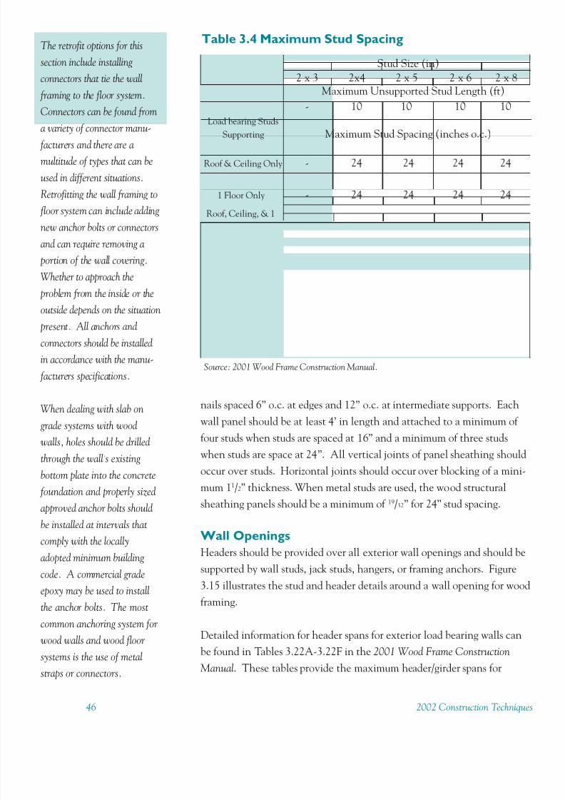
8/11/2019 Protect Home From High Winds
http://slidepdf.com/reader/full/protect-home-from-high-winds 51/7346 2002 Construction Technique
The retrofit options for this
section include installing
connectors that tie the wall
framing to the floor system.
Connectors can be found from
a variety of connector manu-
facturers and there are a
multitude of types that can be
used in different situations.
Retrofitting the wall framing to
floor system can include adding
new anchor bolts or connectors
and can require removing a
portion of the wall covering.
Whether to approach the problem from the inside or the
outside depends on the situation
present. All anchors and
connectors should be installed
in accordance with the manu-
facturers specifications.
When dealing with slab on
grade systems with wood
walls, holes should be drilled
through the wall’s existing
bottom plate into the concrete
foundation and properly sized
approved anchor bolts should
be installed at intervals that
comply with the locally
adopted minimum building code. A commercial grade
epoxy may be used to install
the anchor bolts. The most
common anchoring system for
wood walls and wood floor
systems is the use of metal
straps or connectors.
nails spaced 6” o.c. at edges and 12” o.c. at intermediate supports. Each
wall panel should be at least 4’ in length and attached to a minimum of four studs when studs are spaced at 16” and a minimum of three studs
when studs are space at 24”. All vertical joints of panel sheathing should
occur over studs. Horizontal joints should occur over blocking of a mini-
mum 11/2” thickness. When metal studs are used, the wood structural
sheathing panels should be a minimum of 19/32” for 24” stud spacing.
Wall Openings
Headers should be provided over all exterior wall openings and should be
supported by wall studs, jack studs, hangers, or framing anchors. Figure
3.15 illustrates the stud and header details around a wall opening for wood
framing.
Detailed information for header spans for exterior load bearing walls can
be found in Tables 3.22A-3.22F in the 2001 Wood Frame Construction
Manual. These tables provide the maximum header/girder spans for
Table 3.4 Maximum Stud Spacing
Stud Size (in)
2 x 3 2x4 2 x 5 2 x 6 2 x 8Maximum Unsupported Stud Length (ft)
- 10 10 10 10
Load bearing Studs
Supporting Maximum Stud Spacing (inches o.c.)
Roof & Ceiling Only - 24 24 24 24
1 Floor Only - 24 24 24 24
Roof, Ceiling, & 1
Floor Only - 16 16 24 24
2 Floors Only - 16 16 24 24
Roof, Ceiling, & 2Floors - - - 16 24
Maximum Unsupported Stud Length (ft)
Non-loadbearing 10 14 16 20 20
Studs Maximum Stud Spacing (inches o.c.)
16 24 24 24 24
Source: 2001 Wood Frame Construction Manual.
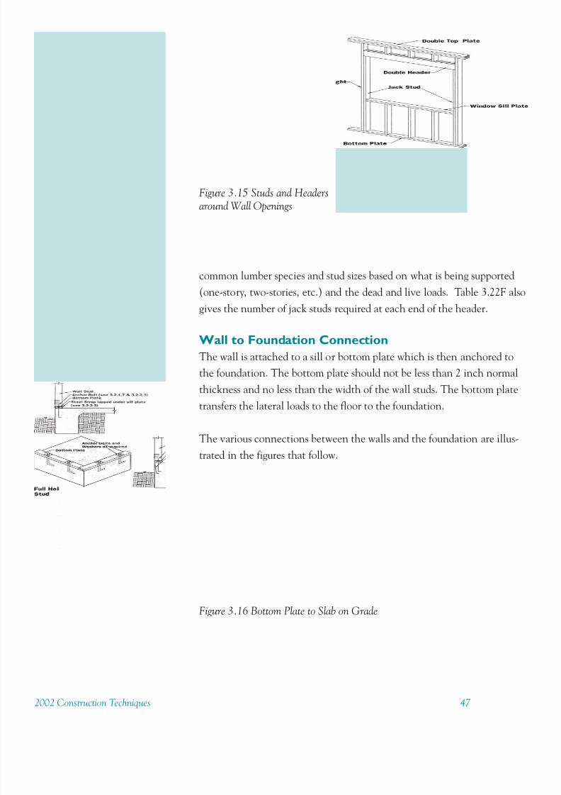
8/11/2019 Protect Home From High Winds
http://slidepdf.com/reader/full/protect-home-from-high-winds 52/732002 Construction Techniques 47
Figure 3.15 Studs and Headers
around Wall Openings
common lumber species and stud sizes based on what is being supported(one-story, two-stories, etc.) and the dead and live loads. Table 3.22F also
gives the number of jack studs required at each end of the header.
Wall to Foundation Connection
The wall is attached to a sill or bottom plate which is then anchored to
the foundation. The bottom plate should not be less than 2 inch normal
thickness and no less than the width of the wall studs. The bottom plate
transfers the lateral loads to the floor to the foundation.
The various connections between the walls and the foundation are illus-
trated in the figures that follow.
Figure 3.16 Bottom Plate to Slab on Grade

8/11/2019 Protect Home From High Winds
http://slidepdf.com/reader/full/protect-home-from-high-winds 53/7348 2002 Construction Technique
Figure 3.18 Wall to Pile Foundation
Figure 3.19 Sill Plate to Concrete Foundation Wall
Figure 3.20 Sill Plate to Masonry Foundation Wall
Figure 3.17 Wall to Permanent Wood Foundation

8/11/2019 Protect Home From High Winds
http://slidepdf.com/reader/full/protect-home-from-high-winds 54/732002 Construction Techniques 49
3.3 FoundationsThe two primary types of floor systems found in residential construction
are concrete and off grade wood floors or a combination of the two.
Connections between the floor system and the foundation system are
important for maintaining the integrity of entire structure from the
ground up. These connections help resist wind forces from tropical
storms, hurricanes or hydrostatic forces from floods and storm surge.
Structures with floor systems not properly connected to the foundation
can be lifted off their foundations and result in extensive damage or total
destruction.
There are many types of foundations used in the construction of residen-
tial structures including concrete slab on grade, concrete footings and
stem walls, piers and piles to name a few. Foundations should be con-
structed on clean compacted fill and should comply with design standardsof the locally adopted minimum building code. Foundation systems
should be connected to the floor system with approved connectors and
installed in compliance with the manufacturers specifications.
Slab-on-Grade Foundations and Footings
Concrete slabs and footings should be poured as a monolithic unit. The
minimum monolithic footing size is 20” thick by 12” wide for one story
buildings and 20” thick by 16” wide for two story buildings. The thickness
includes the thickness of the slab. Either footing size should be reinforced
with two continuous #5 bars.
Wall bottom plates should be anchored to the foundation system with
anchor bolts having a minimum bolt of 5/8” and 3” x 3” x 1/8” washers
spaced 1.5’ o.c. Anchor bolts should be embedded a minimum of 7” in
the bond beam and within 6”-12” of corners and plate ends.
Footings should be level or stepped so that both top and bottom of the
footings are level. The bottom of all footings except for monolithic slab-on-
grade interior footings, should be no less than 12” below finished ground
line. All footings, except for monolithic slab-on-grade foundations, should
be at least 4” wider on each side than the wall resting on the footing.
Floor System to Foundation Connections
The connection between the floor system and the foundation acts to
anchor the house to the earth. This connection completes the load path
To retrofit this connection
properly, it is necessary to
evaluate the anchoring
system used to connect the
floor to the foundation.
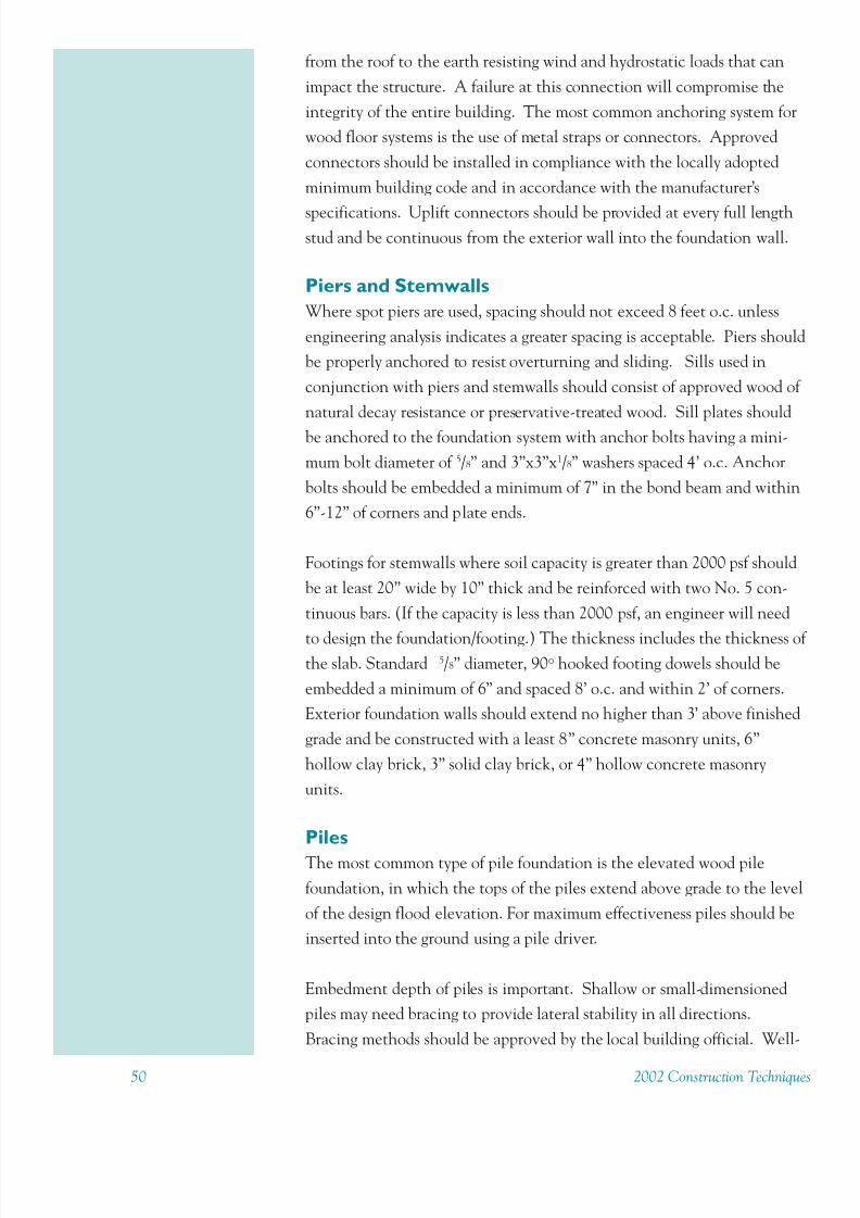
8/11/2019 Protect Home From High Winds
http://slidepdf.com/reader/full/protect-home-from-high-winds 55/7350 2002 Construction Technique
from the roof to the earth resisting wind and hydrostatic loads that can
impact the structure. A failure at this connection will compromise the
integrity of the entire building. The most common anchoring system for
wood floor systems is the use of metal straps or connectors. Approved
connectors should be installed in compliance with the locally adopted
minimum building code and in accordance with the manufacturer’s
specifications. Uplift connectors should be provided at every full lengthstud and be continuous from the exterior wall into the foundation wall.
Piers and Stemwalls
Where spot piers are used, spacing should not exceed 8 feet o.c. unless
engineering analysis indicates a greater spacing is acceptable. Piers should
be properly anchored to resist overturning and sliding. Sills used in
conjunction with piers and stemwalls should consist of approved wood of
natural decay resistance or preservative-treated wood. Sill plates should
be anchored to the foundation system with anchor bolts having a mini-
mum bolt diameter of 5/8” and 3”x3”x1/8” washers spaced 4’ o.c. Anchor
bolts should be embedded a minimum of 7” in the bond beam and within
6”-12” of corners and plate ends.
Footings for stemwalls where soil capacity is greater than 2000 psf should
be at least 20” wide by 10” thick and be reinforced with two No. 5 con-
tinuous bars. (If the capacity is less than 2000 psf, an engineer will need
to design the foundation/footing.) The thickness includes the thickness othe slab. Standard 5/8” diameter, 90o hooked footing dowels should be
embedded a minimum of 6” and spaced 8’ o.c. and within 2’ of corners.
Exterior foundation walls should extend no higher than 3’ above finished
grade and be constructed with a least 8” concrete masonry units, 6”
hollow clay brick, 3” solid clay brick, or 4” hollow concrete masonry
units.
Piles
The most common type of pile foundation is the elevated wood pile
foundation, in which the tops of the piles extend above grade to the level
of the design flood elevation. For maximum effectiveness piles should be
inserted into the ground using a pile driver.
Embedment depth of piles is important. Shallow or small-dimensioned
piles may need bracing to provide lateral stability in all directions.
Bracing methods should be approved by the local building official. Well-

8/11/2019 Protect Home From High Winds
http://slidepdf.com/reader/full/protect-home-from-high-winds 56/732002 Construction Techniques 51
embedded and adequately dimensioned piles may not need bracing– see
local codes. Pile to girder connections can be strengthened using metal
strap connections. Spacing of the straps should comply with local codes.
Corrosion-resistant materials should be used as appropriate; see Appendix
Table C for recommendations.
ConnectorsConnectors can be found from a variety of connector manufacturers and
there are a multitude of types that can be used in different situations. The
use of stainless steel connectors is highly recommended in coastal areas, as
galvanized connectors will rust over time and will need to be replaced
periodically. All connectors and anchor bolts should be installed in
accordance with the manufacturer’s specifications and in compliance with
the locally adopted minimum building code.

8/11/2019 Protect Home From High Winds
http://slidepdf.com/reader/full/protect-home-from-high-winds 57/7352 2002 Construction Technique
Retrofit Standards for Floor
and Foundation Systems
_______________________________________________________________________
3. A. Install Code Compliant AnchoringSystem For Wall to Floor or Wall to
Foundation ConnectionInstall connectors from the wall system to the floor or to the foundation.
Connectors used in anchoring the wall system must satisfy the require-
ments of the locally adopted building code and shall be installed as per
the manufacturers specifications.
3. B. Install Code Compliant AnchoringSystem for Floor to Foundation
ConnectionInstall connectors from the floor system to the foundation. Connectors
used in anchoring the floor system must satisfy the requirements of the
locally adopted building code and shall be installed as per the manufactur
ers specifications. Sills that may have to be replaced during this retrofit
must be replaced with materials of approved wood of natural decay resis-
tance or preservative-treated wood.
3. C. Brace PilesInstall braces on shallow or small-dimensioned piles to provide lateral
stability in all directions. Methods and materials used to brace piles shall
comply with locally adopted building code and shall be installed
according to manufacturer’s specifications.
3. D. Install Code Compliant AnchoringSystem for Girder ConnectionInstall connectors from the girder to piles, piers or stem walls. Connec-
tors used in anchoring the girder must satisfy the requirements of the
locally adopted building code and shall be installed as per the manufactur
ers specifications.

8/11/2019 Protect Home From High Winds
http://slidepdf.com/reader/full/protect-home-from-high-winds 58/732002 Construction Techniques 53
Chapter 4
Concrete and Masonry
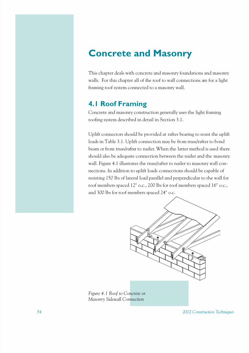
8/11/2019 Protect Home From High Winds
http://slidepdf.com/reader/full/protect-home-from-high-winds 59/7354 2002 Construction Technique
Concrete and Masonry
This chapter deals with concrete and masonry foundations and masonry
walls. For this chapter all of the roof to wall connections are for a light
framing roof system connected to a masonry wall.
4.1 Roof FramingConcrete and masonry construction generally uses the light framing
roofing system described in detail in Section 3.1.
Uplift connectors should be provided at rafter bearing to resist the uplift
loads in Table 3.1. Uplift connection may be from truss/rafter to bond
beam or from truss/rafter to nailer. When the latter method is used there
should also be adequate connection between the nailer and the masonry
wall. Figure 4.1 illustrates the truss/rafter to nailer to masonry wall con-
nections. In addition to uplift loads connections should be capable of
resisting 150 lbs of lateral load parallel and perpendicular to the wall for
roof members spaced 12" o.c., 200 lbs for roof members spaced 16" o.c.,and 300 lbs for roof members spaced 24" o.c.
Figure 4.1 Roof to Concrete orMasonry Sidewall Connection

8/11/2019 Protect Home From High Winds
http://slidepdf.com/reader/full/protect-home-from-high-winds 60/732002 Construction Techniques 55
Gable End Bracing
For masonry wall construction below the gable-end, the same methods as
in Chapter 3 can be completed using bolts instead of nails.
For concrete or masonry walls carried to full roof height, a cast-in-place
rake beam with a 4” or more dimension measured perpendicular to the
slope and one # 5 continuous reinforcing bar should be cast along the rooline (see Figure 4.2). A minimum 2 x 4 wood nailer should be bolted to
the rake beam to connect the wall to roof sheathing.
Connectors
Connectors are available from a variety of connector manufacturers and
there are many types that can be used in different situations. Some of the
applications in this chapter may include the use of a variety of connectors
and anchor bolts. All connectors and anchor bolts should be installed inaccordance with the manufacturers specifications and in compliance with
the locally adopted minimum building code. All connectors should be
corrosion-resistant. See Table C in the Appendix for corrosion resistance
recommendations.
Figure 4.2 Continuous Gable Endwall Reinforcement
If retrofitting, masonry
screws (tapcons) can beused in place of nails assuggested in Chapter 3.
Masonry screws and thespecial bits for drilling the pilot holes are available atmost hardware stores andhome supply centers.
Another alternative is to useretrofit bolts. These boltsare pre-cut threaded rods,supplied with a nut andwasher. A 1 / 2 ” diameter,6" length of retrofit bolt canbe installed every 4’ o.c. Toinstall these bolts, drill a 5 / 8“ diameter hole and remove
the dust from the hole. If the dust is not removed, itwill reduce the epoxy’sholding capacity. Fill thehole halfway with epoxy,starting at the bottom toavoid air pockets. Insert the
bolt, turning it slowly untilit reaches the bottom of thehole.
This connection also can bemade using hurricane clipsor straps to secure the trussto the wall top plate. Clipsor straps can be used onboth masonry and wood
frame construction. Check
with the manufacturer of the chosen connector torecommend the appropriate product and installationmethods.

8/11/2019 Protect Home From High Winds
http://slidepdf.com/reader/full/protect-home-from-high-winds 61/7356 2002 Construction Technique
To retrofit this connection properly, it is necessary toevaluate the anchoring
system used to connect the floor to the foundation.
4.2 Masonry Wall ConnectionExterior concrete and masonry walls should be no less than 8” thick for
high wind regions. Six-inch walls are permitted for one story buildings up
to a maximum ceiling height of 10’ and for the top story of a multistory
building where that story has a maximum ceiling height of 8’. Masonry
walls should include one #5 bar in an 8-inch bond beam at all floor and
roof levels and one #5 bar as vertical reinforcement in a grouted cell at all
corners and spaced at a maximum of 16 ft intervals in exterior walls.
However, the spacing may need to be reduced to as small as 4 ft intervals
based on the building dimensions.
Wall Openings
In addition to the reinforcing above and below a wall opening, reinforcing
may be required on each side of an opening in a masonry wall. One #5
bar should be placed on each side of openings 1' or wider in concrete
walls, and 6' or wider in masonry walls. For openings in masonry walls
wider than 12', two #5 or one #7 bar is required.
4.3 FoundationsThe two primary types of floor systems found in residential construction
are concrete and off grade wood floors or a combination of the two.
Connections between the floor system and the foundation system are
important for maintaining the integrity of entire structure from the
ground up. These connections help resist wind forces from tropical storms
hurricanes or hydrostatic forces from floods and storm surge. Structures
with floor systems not properly connected to the foundation can be lifted
off their foundations and result in extensive damage or total destruction.
The types of foundations used in the construction of concrete and
masonry residential structures include concrete slab-on-grade, concrete
footings and stemwalls. Foundations should be constructed on clean
compacted fill and should comply with design standards of the locallyadopted minimum building code. Foundation systems should be
connected to the floor system with approved connectors and installed in
compliance with the manufacturers specifications.
Slab-on-Grade Foundations and Footings
Slab-on-grade foundations should be monolithic with two #5 continuous
horizontal reinforcing bars. Dimensions are 20” in height including the
slab thickness and 12” wide for one story and 16” wide for two stories.
8/11/2019 Protect Home From High Winds
http://slidepdf.com/reader/full/protect-home-from-high-winds 62/732002 Construction Techniques 57
Footings should be level or stepped so that both top and bottom of the
footings are level. The bottom of all footings, except for monolithic slab-
on-grade interior footings, should be no less than 12" below finished
ground line. All footings, except for monolithic slab- on-grade
foundations, should be at least 4" wider on each side than the wall resting
on the footing. Footing dowel bars should be #5, have a standard 90o
hook, and be embedded 5" into 8" footings and at least 6" into all otherfootings.
Floor System to Foundation Connections
The connection between the floor system and the foundation acts to anchor
the house to the earth. This connection completes the load path from the
roof to the earth resisting wind and hydrostatic loads that can impact the
structure. A failure at this connection will compromise the integrity of the
entire building. The most common anchoring system for wood floor systems i
the use of metal straps or connectors. Approved connectors should be
installed in compliance with the locally adopted minimum building code and
in accordance with the manufacturer’s specifications.
Uplift connectors should be provided at every full length stud and be
continuous from the exterior wall into the foundation wall.
Stemwalls
Foundation stemwalls should be as thick or thicker than the wall
supported, but never less than 8" thick in any case. Each stemwall should
have the same reinforcing as the wall above. Stemwalls should not extend
more than 3' above finished grade.
Footings for stemwalls should be at least 20" wide by 10" thick and be
reinforced with two No.5 continuous bars. The thickness includes the
thickness of the slab.
ConnectorsConnectors can be found from a variety of connector manufacturers and
there are a multitude of types that can be used in different situations. All
connectors should be corrosion resistant. See Appendix Table C for
recommendations. All connectors and anchor bolts should be installed in
accordance with the manufacturer’s specifications and in compliance with
the locally adopted minimum building code.

8/11/2019 Protect Home From High Winds
http://slidepdf.com/reader/full/protect-home-from-high-winds 63/7358 2002 Construction Technique
Retrofit Standards for Floor
and Foundation Systems
_______________________________________________________________________
4.A Install Code Complaint AnchoringSystem for Wall to Floor or Wall to
Foundation ConnectionInstall connectors from the wall system to the floor or to the foundation.Connectors used in anchoring the wall system must satisfy the require-ments of the locally adopted building code and shall be installed as perthe manufacturers specifications.
4.B Install Code Complaint Anchoring
System for Floor to FoundationConnectionInstall connectors from the floor system to the foundation. Connectorsused in anchoring the floor system must satisfy the requirements of thelocally adopted building code and shall be installed as per the manufacturers specifications. Sills that may have to be replaced during this retrofit
must be replaced with materials of approved wood of natural decay resis-tance or preservative-treated wood.
4.C Install Code Complaint Anchoring
System for Girder ConnectionInstall connectors from the girder to piles, piers or stem walls. Connectorsused in anchoring the girder must satisfy the requirements of the locally
adopted building code and shall be installed as per the manufacturersspecifications.

8/11/2019 Protect Home From High Winds
http://slidepdf.com/reader/full/protect-home-from-high-winds 64/732002 Construction Techniques 59
Appendix
Table A: Minimum Roof Sheathing Panel Thickness
3 Second Gust Speed (mph)
90 100 110 120 130Rafter/Truss Spacing
(inches o.c.) Roof SheathingMinimum Panel Thickness
12 3/8" 3/8" 3/8" 3/8" 3/8"
16 3/8" 3/8" 3/8" 3/8" 3/8"
19.2 3/8" 3/8" 3/8" 3/8" 3/8"
24 3/8" 3/8" 3/8" 7/16" 7/16"
Source: 2001 Wood Frame Construction Manual.
-
Southern Yellow Pine (SP) G
3 second Gust Speed (mph)
90 100 110 120 130
Maximum Nail Spacing (inches o.c.)SheathingLocation
Rafter/TrussSpacing
(inches o.c.)
E I E I E I E I E I
12 6 12 6 12 6 12 6 12 6 12
16 6 12 6 12 6 12 6 12 6 6
19.2 6 12 6 12 6 12 6 12 6 6
4' PerimeterEdge Zone
24 6 12 6 6 6 12 6 12 6 6
12 6 12 6 12 6 12 6 12 6 12
16 6 12 6 12 6 12 6 12 6 12
19.2 6 12 6 12 6 12 6 12 6 12Interior Zone
24 6 12 6 12 6 12 6 12 6 12
Table B.1: Roof Sheathing Nailing Schedule: Southern Yellow Pine
Source: 2001 Wood Frame Construction Manual.
E = Nail spacing at panel edges.I = Nail spacing at intermediate supports in the panel field.
-

8/11/2019 Protect Home From High Winds
http://slidepdf.com/reader/full/protect-home-from-high-winds 65/7360 2002 Construction Technique
Spruce Pine Fir (SPF) G<0.49
3 second Gust Speed (mph)
90 100 110 120 130
Maximum Nail Spacing (inches o.c.)SheathingLocation
Rafter/Truss
Spacing(inches o.c.)
E I E I E I E I E I
12 6 12 6 6 6 6 6 6 6 6
16 6 12 6 6 6 6 6 6 6 6
19.2 6 6 6 6 6 6 6 6 4 4
4' PerimeterEdge Zone
24 6 6 6 6 4 4 4 4 4 4
12 6 12 6 12 6 12 6 12 6 4
16 6 12 6 12 6 12 6 12 6 4
19.2 6 12 6 12 6 12 6 12 6 4Interior Zone
24 6 12 6 12 6 12 6 12 6 4
Table B.2: Roof Sheathing Nailing Schedule: Spruce Pine Fir
Source: 2001 Wood Frame Construction Manual.E = Nail spacing at panel edges.
I = Nail spacing at intermediate supports in the panel field.

8/11/2019 Protect Home From High Winds
http://slidepdf.com/reader/full/protect-home-from-high-winds 66/732002 Construction Techniques 61
Recommendations for Corrosion-Resistant Materials and Methods* Source: FEMA TB 8-96
Location
Class of exposure**
Oceanfront Buildings
(300 feet or less from the
shoreline)***
Intermediate Rows of
Buildings in Corrosion-
Prone Areas
(300 to 3,000 feet from the
shoreline)***
Buildings Farther
Landward
(Greater than 3,000 feet
from the shoreline)***
Partially shelteredexteriors
1. Avoid sheetmetalconnectors wherepossible.
2. Use stainless steelconnectors.
3. Use connectors withthicker galvanizingand replace themwhen necessary.
Use connectors withthicker galvanizing.(Optional: stainlesssteel)
Use connectors withstandard galvanizing.(Optional: thickergalvanizing)
Boldly exposed exteriors 1. Avoid sheetmetalconnectors wherepossible.
2. Use stainless steelconnectors.
3. Use connectors withthicker galvanizingand replace themwhen necessary.
Use connectors withthicker galvanizing.(Optional: stainlesssteel)
Use connectors withstandard galvanizing.(Optional: thickergalvanizing)
Vented Enclosurs 1. Use connectors withthicker galvanizing.(Optional: stainlesssteel)
2. Use TPI paints ontruss plates.
(Optional for trussplates: thickergalvanizing, TPI paintsover thicker galvanizing,or stainless steel)
1. Use connectors withthicker galvanizingnear vents.
2. Use TPI paints ontruss plates nearvents.
(Optional: thickergalvanizing for allconnectors)
Use connectors withstandard galvanizing.(Optional: thickergalvanizing)
Interior living space Use connectors withstandard galvanizing.(Optional: thickergalvanizing)
Use connectors withstandard galvanizing.(Optional: thickergalvanizing)
Use connectors withstandard galvanizing.(Optional: thickergalvanizing)
* Recommendations are based on the available research and are subject to change in future Technical
Bulletins.
** see Figure 5 in FEMA's TB 8-96 for corrosion classes.
*** Distances may vary considerably depending on local climate. The width of the corrosion hazard area
relative to the ocean should be determined in each community from field observations and any existing
corrosion studies.
Table C: Corrosion
Care should also be taken to ensure that connectors and fasteners used near salt water are
corrosion-resistant. The Federal Emergency Management Agency (FEMA) has adocument, TB 8-96: Corrosion Protection for Metal Connectors in Coastal Areas, that
discusses corrosion resistance in detail; recommendations are summarized below.
Note: To obtain the FEMA document, call 800/480-2520 and request TB 8-96, ordownload it from http://www.fema.gov/mit/techbul.htm.
Vented enclosures
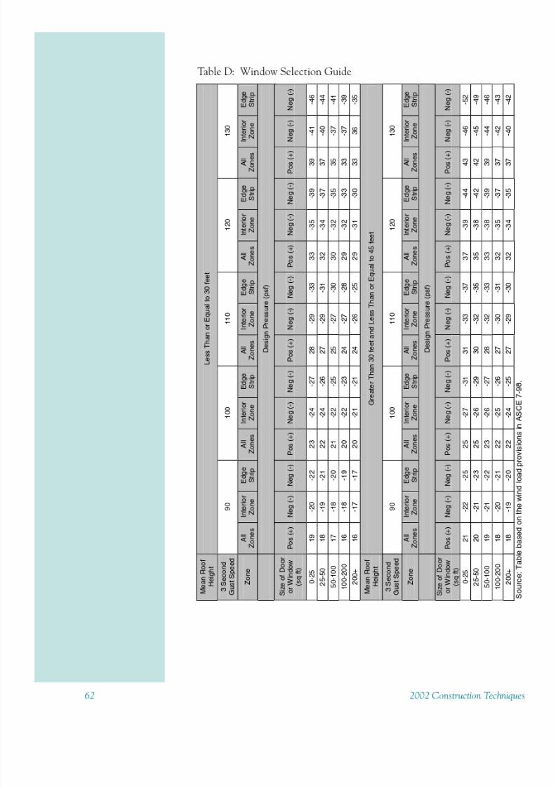
8/11/2019 Protect Home From High Winds
http://slidepdf.com/reader/full/protect-home-from-high-winds 67/73

8/11/2019 Protect Home From High Winds
http://slidepdf.com/reader/full/protect-home-from-high-winds 68/732002 Construction Techniques 63
Table E: Required Uplift Loads
Three Second Gust Wind Speed 90 100 110 120 130 140
Roof/Ceiling AssemblyDesign Dead Load
(psf)
Roof Span(ft.)
Required Uplift Capacity of Connection (lbs.)
12 134 165 199 237 279 323
24 219 271 328 390 458 531
36 306 378 457 544 639 7410
48 393 485 587 698 820 951
12 86 117 151 189 231 275
24 135 187 244 306 374 447
36 186 258 337 424 519 62110
48 237 329 431 542 664 795
12 62 93 127 165 207 251
24 93 145 202 264 332 405
36 126 198 277 364 459 56115
48 159 251 353 464 586 717
12 38 69 103 141 183 227
24 51 103 160 222 290 363
36 66 138 217 304 399 50120
48 81 173 275 386 508 639
12 14 45 79 117 159 203
24 9 61 118 180 248 321
36 6 78 157 244 339 44125
48 3 95 197 308 430 561
Source: 2001 Wood Frame Construction Manual.Values are based on a 12" spacing. To determine connection requirement for different connectorspacing, multiply by the appropriate load multiplier below:
Connection Spacing (in.) 16 19.2 24 48
Load Multiplier 1.33 1.6 2 4
Tabulated uplift loads assume a building located in Exposure B with a mean roof height of 33feet.
48
4
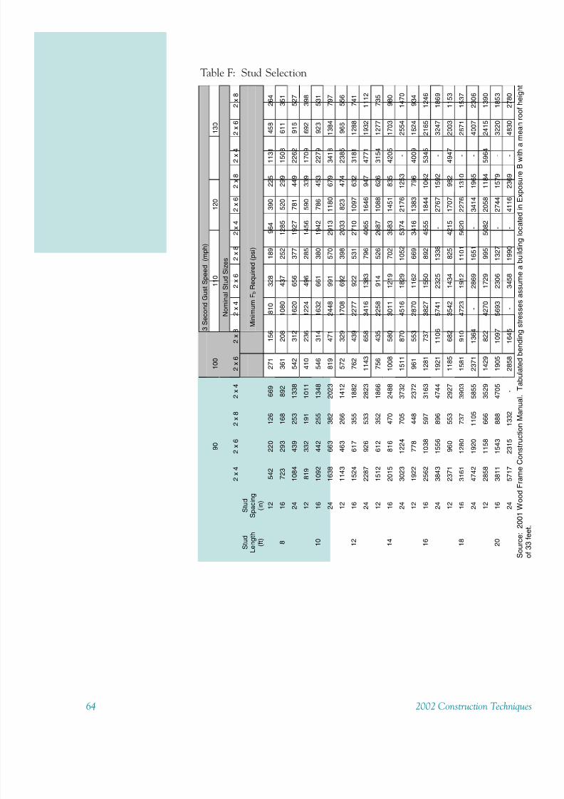
8/11/2019 Protect Home From High Winds
http://slidepdf.com/reader/full/protect-home-from-high-winds 69/7364 2002 Construction Technique
Table F: Stud Selection
3SecondGustSp
eed
(mph)
90
100
110
120
130
NominalStud
Sizes
2x4
2x6
2x
8
2x4
2x6
2x8
2x4
2x
6
2x8
2x4
2x6
2x8
2x4
2x6
2x8
Stud
Length
(ft)
Stud
Spacing
(in)
Minimum
F b
Req
uired(psi)
12
542
220
12
6
669
271
156
810
328
189
964
390
225
1131
458
264
16
723
293
16
8
892
361
208
1080
437
252
1285
520
299
1508
611
351
8
24
1084
439
25
3
1338
542
312
1620
656
377
1927
781
449
2262
916
527
12
819
332
19
1
1011
410
236
1224
496
285
1456
590
339
1709
692
398
16
1092
442
25
5
1348
546
314
1632
661
380
1942
786
453
2279
923
531
10
24
1638
663
38
2
2023
819
471
2448
991
570
2913
1180
679
3418
1384
797
12
1143
463
26
6
1412
572
329
1708
692
398
2033
823
474
2385
966
556
16
1524
617
35
5
1882
762
439
2277
922
531
2710
1097
632
3181
1288
741
12
24
2287
926
53
3
2823
1143
658
3416
138
3
796
4065
1646
947
4771
1932
1112
12
1512
612
35
2
1866
756
435
2258
914
526
2687
1088
626
3154
1277
735
16
2015
816
47
0
2488
1008
580
3011
121
9
702
3583
1451
835
4205
1703
980
14
24
3023
1224
70
5
3732
1511
870
4516
182
9
1052
5374
2176
1253
-
2554
1470
12
1922
778
44
8
2372
961
553
2870
116
2
669
3416
1383
796
4009
1624
934
16
2562
1038
59
7
3163
1281
737
3827
155
0
892
4555
1844
1062
5345
2165
1246
16
24
3843
1556
89
6
4744
1921
1106
5741
232
5
1338
-
2767
1592
-
3247
1869
12
2371
960
55
3
2927
1185
682
3542
143
4
825
4215
1707
982
4947
2003
1153
16
3161
1280
73
7
3903
1581
910
4723
191
2
1101
5620
2276
1310
-
2671
1537
18
24
4742
1920
110
5
5855
2371
1364
-
286
9
1651
-
3414
1965
-
4007
2306
12
2858
1158
66
6
3529
1429
822
4270
172
9
995
5082
2058
1184
5964
2415
1390
16
3811
1543
88
8
4705
1905
1097
5693
230
6
1327
-
2744
1579
-
3220
1853
20
24
5717
2315
133
2
-
2858
1645
-
345
8
1990
-
4116
2369
-
4830
2780
Source:2001WoodFrameConstructionM
anual.Tabulatedbendingstressesassum
eabuildinglocatedinExposureBwitham
eanroofheight
of33feet
8/11/2019 Protect Home From High Winds
http://slidepdf.com/reader/full/protect-home-from-high-winds 70/732002 Construction Techniques 65
Reference Materials for High Wind Construction
American Forest & Paper Association (AF&PA)Wood Frame Construction Manual(2001 High Wind Edition)American Wood Council of AF&PATechnical PublicationsPO Box 5364Madison, WI 53705-5364800-890-7732
www.awc.org
Federal Emergency Management Agency (FEMA)Coastal Construction Manual
[FEMA publications are free; ask for FEMA 55, the Coastal Construction
Manual, and FEMA 20, a catalog of available publications.]
800-480-2520www.fema.gov
Southern Building Code Congress (SBCCI)SSTD 10-99 Standard for Hurricane Resistant ResidentialConstructionSouthern Building Code Congress International, Inc.900 Montclair RoadBirmingham, Alabama 35213-1206 USA205-591-1853www.sbcci.org
Sources of Additional Information
American Society of Civil Engineers1801 Alexander Bell DriveReston, VA 20191-4400800-548-2723www.asce.org
Blue Sky Foundation of NC
920 Main Campus Drive, Suite 100Raleigh, NC 27606919-424-4555 or 919-424-4401 Faxwww.bluesky-foundation.com
FEMA Region IVMitigation Division
3003 Chamblee Tucker Rd.Atlanta, GA 30341770-220-5485

8/11/2019 Protect Home From High Winds
http://slidepdf.com/reader/full/protect-home-from-high-winds 71/7366 2002 Construction Technique
Florida Alliance for Safe Homes (FLASH)1430 Piedmont Drive EastTallahassee, FL 32308877-221-SAFEwww.flash.org
Institute for Business & Home Safety1408 North Westshore Blvd.
Suite 208Tampa, FL 33607866-657-IBHSwww.ibhs.org
North Carolina Sea Grant Extension ProgramCoastal Construction and Erosion Specialist5001 Masonboro Loop Road
Wilmington, NC 28409910-962-2491 or 910-962-2410 fax
www.ncsu.edu/seagrant/
South Carolina Sea Grant Extension ProgramCoastal Hazards Specialist287 Meeting StreetCharleston, SC 29401843-727-6497 or 843-727-0191 fax
www.scseagrant.org
Materials Sources
Sources of Adhesive Weather Stripping Material:
MFM Building Products Corporation800-882-ROOFwww.coshocton.com/mfm/
Protecto Wrap Co800-759-9727
www.protectowrap.com
Bartech International800-341-9917www.ridglass.com

8/11/2019 Protect Home From High Winds
http://slidepdf.com/reader/full/protect-home-from-high-winds 72/732002 Construction Techniques 67
Sources of Automatic Feed Screw Guns:
Quik Drive Corporation888-487-7845www.quikdrive.com
Pam Fastening Technology, Inc800-699-2674
Grabber Construction Products800-477-TURNwww.grabberman.com
Makita USA800-462-5482www.makita.com
Stanley-Bostitch
401-884-2500www.stanleyworks.com
Sources of Power/Pressure Operated Caulk Guns:
Grainger
864-288-0110www.grainger.com
McMaster Carr
404-346-7000www.mcmaster.com
MSC
800-645-7270www.mscdirect.com
Tool Crib of the North800-358-3096www.toolcrib.amazon.com
Caulkmaster800-447-6326
www.caulkmaster.com
Tools-Plus800-222-6133www.tools-plus.com

8/11/2019 Protect Home From High Winds
http://slidepdf.com/reader/full/protect-home-from-high-winds 73/73
Finding AFG-01 Rated Adhesives:These adhesives are readily available at home improvement stores.Check for the AFG-01 rating on the tube. These adhesives were largelydeveloped for subfloor applications. You can usually locate them byasking for the subfloor adhesives.
Sources of High-Wind Asphalt Shingles
Tamko Roofing ProductsStormfighter Shingle800-228-2656www.tamko.com
Certainteed CorporationHatteras Shingle610-341-7000
www.certainteed.com
Sources of Metal Connectors/“Hurricane Clips”:
Simpson Strong-Tie800-999-5099www.strongtie.com
USP Lumber Connectors800-227-0470www.uspconnectors.com
Acknowledgements
This guide was prepared by Clemson University graduate studentsMelanie Frank and Alana Walden, under supervision of Dr. Scott Schiff,
Associate Professor of Civil Engineering at Clemson University and Dr.Elizabeth Judge, Coastal Hazards Specialist for the S.C. Sea GrantExtension Program, in cooperation with Mr. Don Markle, Executive
Di t f th Bl Sk F d ti f N th C li I Q ti