proposedconfigurationsfortheuseofsmartdamperswith...
TRANSCRIPT

Hindawi Publishing CorporationSmart Materials ResearchVolume 2012, Article ID 251543, 16 pagesdoi:10.1155/2012/251543
Research Article
Proposed Configurations for the Use of Smart Dampers withBracings in Tall Buildings
A. M. Aly Sayed Ahmed,1, 2 Alberto Zasso,3 and Ferruccio Resta3
1 Department of Mechanical Engineering, Faculty of Engineering, Alexandria University (on leave), Alexandria, Egypt2 Department of Civil and Environmental Engineering, The University of Western Ontario, London, ON, Canada3 Department of Mechanical Engineering, Politecnico di Milano, Milan, Italy
Correspondence should be addressed to A. M. Aly Sayed Ahmed, [email protected]
Received 30 June 2011; Revised 15 December 2011; Accepted 15 December 2011
Academic Editor: Marcelo A. Trindade
Copyright © 2012 A. M. Aly Sayed Ahmed et al. This is an open access article distributed under the Creative CommonsAttribution License, which permits unrestricted use, distribution, and reproduction in any medium, provided the original work isproperly cited.
This paper presents wind-induced response reduction in a very slender building using smart dampers with proposed bracings-lever mechanism system. The building presents a case study of an engineered design that is instructive. The paper shows thatshear response and flexural response of tall buildings present two very different cases for vibration suppression. Smart dampersare implemented optimally in the building to reduce its response in the lateral directions for both structural safety and occupantcomfort concerns. New bracings-lever mechanism configurations are proposed for the dampers to improve their performance.The study shows how the proposed configurations can enable application to flexural response and scenarios where the interstorydrift is not enough for dampers to work effectively. In addition, a decentralized bang-bang controller improved the performanceof the smart dampers.
1. Introduction
In tall buildings, wind-induced vibrations may cause annoy-ance to the occupants (especially in the upper floors),impaired function of instruments, or structural damage.Safer and more efficient designs are sought out to balancethese issues with the reality of limited resources. Structuralcontrol can potentially provide more efficient structures. Thepurpose of structural control is to absorb and to reflect theenergy introduced by dynamic loads. Passive, active, andsemiactive types of control strategies have been proposed andimplemented in a number of civil structures.
Although tuned mass dampers (TMDs) and active tunedmass dampers (ATMDs) are shown to be effective in reducingthe response of tall buildings under wind loads [1–5], theyare large, heavy, and take up valuable space buildings top.Moreover, they present additional cost to the project. Viscousdampers and semiactive dampers can be used as alternativesto overcome the difficulties associated with the application ofTMDs and ATMDs. These devices do not require frequencytuning [6]. It is therefore sometimes possible to damp severalmodes with one device.
Smart damping technology is a type of semiactive controlthat employs variable dampers (e.g., variable orifice, mag-netorheological fluid, and electrorheological fluid dampers).Smart damping technology assumes the positive aspectsof both passive and active control devices; it can provideincreased performance over passive control without theconcerns of energy and stability associated with activecontrol. Due to its low power requirements and fail-safeproperty, magnetorheological (MR) dampers have beenshown to mesh well with application demands to offer anattractive means of protecting civil infrastructure systemsagainst severe earthquake and wind loading [7–10]. MRdamper is a kind of viscous damper, in which the viscousforce generated in the damper can be controlled.
The challenge in using such devices for tall buildingsis related to where to put the device in the building. Intall buildings, it is required that the damper is connectedbetween two points where a significant displacement isexpected. Unlike short and shear buildings, in which floorrotational angles are very small and there may be a significantinterstory drift under dynamic loads, slender tall buildingsmay vibrate like a cantilever. Cantilever-like behavior of

2 Smart Materials Research
1st mode 2nd mode 3rd mode 4th mode 5th mode 6th modey x
z
(a)
Spatial model
Y
X
Modal model
Z
(b)
Figure 1: Finite element (FE) model of the tower with the coordinate system: the wind direction 0◦ is along the x-axis.
buildings makes it very difficult to have an effective internalbracing system (interstory shear drift is usually not sufficientfor a damper to work effectively).
Constantinou et al. [11] tested a motion amplificationdevice called Toggle Brace Damper system (TBD) to amplifyinterstory motion. However, the efficiency of the TBD systemis highly dependent on various local system parameters[12]. McNamara and Taylor [13] presented an application oftoggle brace damper system in a high-rise structure to sup-press the anticipated wind-induced accelerations. To providesome compactness to the TBD, Sigaher and Constantinou[14] introduced the scissor-jack-damper system. Bertonand Bolander [15] described a displacement amplificationdevice (DAD) based on a gear-type mechanism connectedin series with a fluid viscous damper (FVD). Lee et al. [16]investigated the effectiveness of a toggle brace system thatuses MR damper in a building structure for seismic responsereduction. Walsh et al. [17] conducted numerical simulationsto investigate scissor-jack dampers for controlling vibrationsin a seismically excited flexible truss tower.
In this paper, the building under consideration is shownto behave in one lateral direction-like shear buildings (x-direction) and in the other direction as cantilever structures(y-direction). For the x-direction, internal bracings with MRdampers are used, while, for the y-direction, outer bracingswith MR dampers are proposed. Since the displacementacross the damper is shown to be small, a lever mecha-nism is proposed for motions magnification. Both passive-on and decentralized bang-bang controllers showed thatMR dampers with the proposed bracings-lever mechanismconfigurations are effective in reducing the responses of thebuilding under wind loads in the two lateral directions.
2. Modeling of the Building
The full-scale building has a height of 221.3 m above groundand a rectangular cross-section of B/D = 2.56 (B:chord length, D: thickness). The aspect ratio is about 10,which makes it very slender and sensitive to strong winds.The overall buildings mass is about 1.4 × 10⁵ ton. Thestructure has 50 stories above ground level. There are fourunderground stories. The first six modes of the buildingare shown in Figure 1(a). The first six natural frequencies
are 0.122 Hz, 0.135 Hz, 0.461 Hz, 0.647 Hz, 1.079 Hz, and1.083 Hz, respectively.
Although finite element software packages can help toprovide mode shapes, modal masses, and modal frequenciesfor a desired number of modes, it does not provide infor-mation about damping in buildings. This is because, unlikemass and rigidities that are distributed along the elements,damping, however, is related to friction between joints andsome hysteresis in the material and there is no convenientmean to refine the predictive capabilities regarding inherentstructural damping, owing to its association with a numberof complex mechanisms and even nonstructural elements.
While the best way to get information about damping isto go on site and measure it, there have been some effortsto develop empirical predictive tools for damping estimationbased on full-scale observations [6, 18]. Tamura and Yoshida[19] presented a damping predictor for tall buildings thatis dependent on the vibrations amplitude. The formula forreinforced concrete buildings is given by
ζ = 0.93H
+ 470xHH− 0.0018, (1)
where ζ is the first modal damping, xH is the displacementat the top of the building, and H is the buildings height.For xH = 0.5 m and overall building height of about 240 m(including underground stories), the damping factor fromthe above equation is about 1%. For xH = 0.25 m and1 m, the corresponding damping factors are .5% and 2%,respectively. However, the damping factor for the Isozakitower is assumed to be 1%. For control purposes, a lumped-masses model is derived from the original FEM. In thismodel, the mass of the building is lumped at the positions offloors (Figure 1(b)). In general, equation of motion for an n-story building moving in both the two transverse directionsand in torsion is written as
Msx + Csx + Ksx = −F + Λf , (2)
where x = [XYΘ]T . The terms X = [x1 x2 . . . xn] andY = [y1 y2 . . . yn] are row vectors of the displacements ofthe center of mass of each floor in the x and y directions,respectively, and Θ = [θ1 θ2 . . . θn] is the vector of therotations of each floor about the vertical axis (z-axis), while

Smart Materials Research 3
n is the number of stories. Ms, Ks, and Cs are mass, stiffness,and damping matrices, respectively.
The stiffness matrix of the spatial model is obtainedby assuming the stiffness between floors as a combinationof cantilever and shear rigidities. MATLAB codes [20] arewritten and used to derive the best stiffness matrix that givesthe closest mode shapes to those of the FEM and the samefirst six natural frequencies.
The mass matrix Ms has the following form:
Ms =⎡⎢⎣
M 0 00 M 00 0 I
⎤⎥⎦, (3)
where M = diag([m1 m2 . . . mN ]) is the diagonal N × Nmatrix of masses of each floor, and I = diag([I1 I2 . . . IN ]),where Ii is the moment of inertia of the ith floor. N = totalnumber of floor. The stiffness matrix of the spatial modelis obtained by assuming the stiffness between floors as acombination of cantilever and shear rigidities. MATLAB [20]codes are written and used to derive the best stiffness matrixthat gives the closest mode shapes to those of the FEM andalmost the same first six natural frequencies. The stiffnessmatrix Ks has the form
Ks =⎡⎢⎣
Kx 0 00 Ky 00 0 Kθ
⎤⎥⎦, (4)
where Kx, Ky , and Kθ are the stiffness matrices in the trans-verse directions (x and y) and the torsional direction, respec-tively.
The most effective way to treat damping within modalanalysis framework is to consider the damping value as anequivalent Rayleigh Damping in the form of [21]
Cs = α Ms + β Ks, (5)
in which Cs is the damping matrix; α and β are predefinedconstants. After having the damping matrix, the modaldamping vector is calculated for all of the vibrational modesand the first six-modal damping is taken to be equal to avalue of 1% which is the same value as assumed for theFEM. After adjusting the first six-modal damping factors, thedamping matrix is reconstructed again. To obtain the damp-ing matrix, Cs, using modal damping factors [22], at normalmodes (when the equations of motion are decoupled), theequations of motion for free damped vibration take the form
MX + CD X +[ω2] X = 0, (6)
where
CD = [uu]T[Cs][uu] = 2Ms[ω][ζ], (7)
in which [uu] is the matrix of orthonormal modes asso-ciated with the eigenvalue problem (eigenvectors), [ω] isdiagonal matrix of undamped natural frequencies, and [ζ] is
a diagonal matrix of modal damping. In (2), the disturbanceF = [FxFyT]T is a vector of excitation in which Fx and Fy
are two vectors of the horizontal loads acting in the x andy directions, respectively, and T is a vector of the externaltorsional wind loads. Also, f is the vector of control forces,where its coefficient matrix Λ is the matrix determined bythe location of control devices.
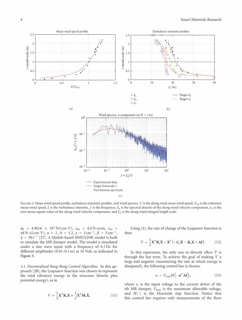
Wind-loading vectors (Fx, Fy , and T) lumped at theposition of floors are obtained from wind tunnel testsconducted at the wind tunnel of Politecnico di Milano[23] on a scaled 1 : 100 rigid model of the tower. Thewind profile represents a typical urban terrain, as shownin Figure 2. The reference mean wind speed (Uref) wasmeasured at a height of 1 m. The target for the wind profilesis the Eurocode 1 [24]. The turbulence intensities in thelongitudinal, lateral, and vertical directions are referred toby Iu, Iv, and Iw, respectively. Further details about the windtunnel experiment are given in Aly et al. [5]. Pressure dataon the outer surface of the rigid model were acquired, andthen the corresponding time histories of the wind excitationforces were calculated at the position of each floor.
The uncontrolled acceleration and displacement re-sponses of the tower in the two lateral directions (x-di-rection and y-direction) were evaluated for 16 different windexposures. The response of the tower was shown to be outof the comfort limit. Wind loads at exposures correspondingto the maximum responses in the two lateral directions areconsidered in this paper (more description about wind loadsestimation and the associated buildings response is providedin Aly [25]). A damping mechanism is needed for both safetyand comfort reasons.
3. MR Dampers
An MR damper model with a maximum capacity of 1000 kNis used in this paper. The MR damper is mathematicallymodeled using the Bouc-Wen model. This model wasdeveloped and shown to accurately predict the behaviorof the MR damper over a wide range of inputs [26]. Theequations governing the force, f , predicted by this model areas follows:
f = c0x + αz, z = γ|x|z|z|n−1 − βx|z|n + Ax, (8)
where z is the evolutionary variable that accounts for thehistory dependence of the response. The model parametersdepend on the voltage, v, to the current driver as follows:
α = αa + αbu, c0 = cx0a + c0bu, (9)
where u is given as the output of the first-order filter
u = −η(u− v). (10)
Equation (10) is used to model the dynamics involvedin reaching rheological equilibrium and in driving the elec-tromagnet in the MR damper. The parameters of the MRdamper were selected so that the device could providea capacity of 1000 kN as follows: αa = 1.0872e5 N/cm,
4 Smart Materials Research
0 0.5 1 1.50
0.5
1
1.5
2
2.5Mean wind speed profile
zm
odel
sca
le (
m)
U/Uref
(a)
0 10 20 30 400
0.5
1
1.5
2
2.5Turbulence intensity profiles
zm
odel
sca
le (
m)
Ii (%)
IuIwIv
Target-IuTarget-Iv
(b)
Experimental dataTarget Eurocode 1 Von Karman spectrum
Wind spectra, u-component (at H = 1 m)100
100 101 102
10−1
10−1
10−2
10−210−3
S u(f
)∗
f/σ
2 u
f ∗ Lxu/U
(c)
Figure 2: Mean wind speed profile, turbulence intensity profiles, and wind spectra. U is the along wind mean wind speed, Uref is the referencemean wind speed, Ii is the turbulence intensity, f is the frequency, Su is the spectral density of the along wind velocity component, σu is theroot mean square value of the along wind velocity component, and Lxu is the along wind integral length scale.
αb = 4.9616 × 10⁵ N/(cm·V), c0a = 4.4 N·s/cm, c0a =44 N·s/(cm·V), n = 1, A = 1.2, γ = 3 cm−1, β = 3 cm−1,η = 50 s−1 [27]. A Matlab-based SIMULINK model is builtto simulate the MR damper model. The model is simulatedunder a sine wave input with a frequency of 0.1 Hz fordifferent amplitudes (0.01–0.1 m) at 10 Volt, as indicated inFigure 3.
3.1. Decentralized Bang-Bang Control Algorithm. In this ap-proach [28], the Lyapunov function was chosen to representthe total vibratory energy in the structure (kinetic pluspotential energy), as in
V = 12
XTKsX +12
XTMsX. (11)
Using (2), the rate of change of the Lyapunov function isthen
V = 12
XTKsX + XT(−CsX−KsX + Λf
). (12)
In this expression, the only way to directly effect V isthrough the last term. To achieve the goal of making V alarge and negative (maximizing the rate at which energy isdissipated), the following control law is chosen:
vi = VmaxH(−xTΛf
), (13)
where vi is the input voltage to the current driver of theith MR damper, Vmax is the maximum allowable voltage,and H(·) is the Heaviside step function. Notice thatthis control law requires only measurements of the floor

Smart Materials Research 5
Table 1: Modal drifts normalized to be 1 m at the top of the building.
Floors Height (m)x-direction y-direction
Lb (m) L′b (m) δ (m) Lb (m) L′b (m) δ (m)
Base-0 19.100 48.446 48.459 0.013 28.147 28.150 0.003
0–6 32.800 55.626 55.691 0.065 39.212 39.219 0.007
6–11 20.500 49.449 49.527 0.078 29.808 29.816 0.008
11–16 20.500 49.449 49.537 0.088 29.808 29.816 0.008
16–21 20.500 49.449 49.537 0.088 29.808 29.816 0.008
21–26 20.500 49.449 49.522 0.073 29.808 29.816 0.008
26–31 20.500 49.449 49.525 0.076 29.808 29.816 0.008
31–36 20.500 49.449 49.531 0.082 29.808 29.817 0.009
36–41 20.500 49.449 49.526 0.077 29.808 29.816 0.008
41–46 20.500 49.449 49.514 0.065 29.808 29.814 0.006
46–50 24.300 51.285 51.336 0.051 32.763 32.768 0.005
0 5 10
0
1
210 Volts
Forc
e (N
)
Velocity (m/s)
−1
−5−2−10
×106
0.01 m 0.05 m0.02 m 0.1 m
Figure 3: Comparison between the damper force under differentamplitudes; 0.1 Hz sinusoidal displacement excitation at an inputvoltage of 10 volts.
velocities (only those in contact with the MR dampers) andapplied control forces.
4. Optimum Placement of Dampers
4.1. Target Positions for the Dampers. Tall buildings usuallyhave stiff stories, and the relative displacement betweenadjacent floors is usually small, which makes it difficult toput dampers between two successive floors. A good methodto check drifts in tall buildings is to consider the first lateralmode shape in the direction where it is necessary to damp thevibrations. The floors that have reasonable shear drift may beselected for dampers to be mounted in between. Figure 4 isa schematic drawing of floors 16 and 21 before and after thefirst modal deformations. Modal deformations of the floorsare normalized to be 1 m at the top of the tower and scaled upby 10 for better visualization. On the figure, Lb is the diagonal(bracing) length before deformation and L′b is the length afterdeformation, while αx and αy represent floors rotation anglesin x-direction and y-direction, respectively. It is shown thatαy is much more than αx which means that the floors are
rotating much more in the y-direction. This is also relatedto the unequal aspect ratios which are about 3.8 in the x-direction and about 9.3 in the y-direction (the aspect ratio iscalculated using the overall height of the tower including theunderground floors).
Table 1 gives the first modal diagonal displacementsbetween each two successive floors of “base, 0th, 6th, 11th,16th, 21st, 26th, 31st, 36th, 41st, 46th, and 50th floors.”The displacements are normalized to be 1 m at the top ofthe tower in each lateral direction. Again, one can see thatthe drifts in the x-direction are much more than those inthe y-direction. By looking at the numbers of Table 1 andtaking into account that there will be some elongations inthe bracing member itself which will be considered negativeswith respect to these numbers, the efficiency of the betweenfloors dampers in the y-direction will be limited. However,the deformations in the x-direction (except the deformationbetween the base and the 0th floor) are large enough fordampers to work properly.
Based on the drift characteristics of the building inthe two lateral directions, dampers may be placed betweenfloors with internal bracings for vibration reduction in thex-direction. For vibration reduction in the y-direction, itmay be placed with outer bracings. Figure 5 shows suggestedpositions for dampers placement in the x- and y-directions.
4.1.1. Placement in the x-Direction. To know exactly whicharrangement of dampers is the best, one may assume thatideal viscous dampers are placed between each two selectedsuccessive floors (those used in Table 1), then the modaldamping factors of the building with dampers can beestimated analytically. Viscous dampers used are assumedto be linear, and their constitutional force deformationrelationship may be expressed as
Fd = Cdx, (14)
where Fd and x are the resistance force and deformationof the damper, respectively. Cd is the damping coefficientof the viscous damper. Using the complex eigenvalue λ, the

6 Smart Materials Research
Floor 21
Floor 16
αxLb
Lb
(a)
Floor 21
Floor 16
Lb
αy
Lb
(b)
Figure 4: Modal deformations of floors number 16 and 21.
Dampers
Bracing
Floor 0
Floor 6
Floor 11
Floor 16
Floor 21
Floor 26
Floor 31
Floor 36
Floor 41
Floor 46
Floor 50
z-axis
x-axisBase −4
(a)
Outerbracing
technique
z-axis
y-axis
(b)
Figure 5: Suggested positions for dampers placement.
modal damping ratio, ζ , is obtained as follows (concerningith mode):
λi = Re(λi) + j Im(λi) = −ζiωi + jωi
√1− ζ2
i , (15)
where j = √−1, “Re” refers to the real part, “Im” refers tothe imaginary part, and
ωi =√
Re (λi)2 + Im (λi)
2 = |λi|,
ζi = −Re(λi)√Re (λi)
2 + Im (λi)2= −Re
(λi|λi|
).
(16)
First, optimization is based on viscous dampers, and,later, MR dampers will be used. Figure 6 shows the effect
of dampers placement and their capacity on the first twolateral modal damping factors of the building in the x-direction. Due to the nature of the wind excitation andthe fact that the first modal frequencies of the buildingare separated, the first mode is the most important oneto be damped. On the figure, uniformly distributed casemeans that the total amount of damping equally distributedbetween stories. In this case, as indicated on the figure, it isnot the most effective one if the target is to provide higherdamping to the first mode. Dampers position “betweenbase and 0th story” is providing little amount of damping,especially for the first mode, which is better to excludethis position. Dampers positions “between 11th and 16th”and “between 16th and 21st” are shown to provide higheramount of damping to the first mode. Dampers position

Smart Materials Research 7
0 0.5 1 1.5 2 2.5 30
1
2
3
4
5
6
7
8Fi
rst
mod
al d
ampi
ng
rati
o (%
)
Between base and 0 storyBetween 0 and 6th storiesBetween 6th and 11th storiesBetween 11th and 16th storiesBetween 16th and 21st storiesBetween 21st and 26th storiesBetween 26th and 31st storiesBetween 31th and 36th storiesBetween 36th and 41st storiesBetween 41st and 46th storiesBetween 46th and 50th storiesUniformly distributed
Total viscous dampers capacity (N·s/m) ×108
(a)
Between base and 0 storyBetween 0 and 6th storiesBetween 6th and 11th storiesBetween 11th and 16th storiesBetween 16th and 21st storiesBetween 21st and 26th storiesBetween 26th and 31st storiesBetween 31th and 36th storiesBetween 36th and 41st storiesBetween 41st and 46th storiesBetween 46th and 50th storiesUniformly distributed
0 0.5 1 1.5 2 2.5 30
1
2
3
4
5
6
7
8
Seco
nd
mod
al d
ampi
ng
rati
o (%
)
Total viscous dampers capacity (N·s/m) ×108
(b)
Figure 6: Modal damping ratio versus total capacity of viscous dampers (x-direction).
0 0.5 1 1.5 2 2.5 30
2
4
6
8
10
12
Firs
t m
odal
dam
pin
g
0 story1st story6th story11th story
16th story21st story26th story31st story
Overall capacity of viscous dampers (N·s/m) ×108
rati
o (%
)
(a)
3
0 story1st story6th story11th story
16th story21st story26th story31st story
0 0.5 1 1.5 2 2.50
2
4
6
8
10
12
14
Seco
nd
mod
al d
ampi
ng
Overall capacity of viscous dampers (N·s/m)
rati
o (%
)
×108
(b)
Figure 7: Modal damping ratio versus total capacity of viscous dampers (y-direction).
“between 16th and 21st” provides slightly higher dampingto the first mode than dampers position 11th and 16th.”However, dampers position “between 11th and 16th” canprovide higher damping in the second mode than dampersposition “between 16th and 21st,” which may be better forhigher frequency excitations (e.g., earthquakes).
4.1.2. Placement in the y-Direction. The placement of dam-pers in the y-direction is between floors and ground asindicated on Figure 5(b). The point of fixing the damperwith ground is considered to be unchangeable, while the
optimum position to which the other part of the link is tobe connected is to be found. Eight different bracing positionsincluding between ground and one of the stories number 0,6, 11, 16, 21, 26, and 31 are considered. Figure 7 gives thefirst two lateral modal damping factors of the building in they-direction against dampers capacity for different bracingpositions. It is shown that as the link is connected to higherstories the first modal damping is increasing. However, thehighest amount of damping to the second mode is providedwhen the link is connected between ground and the 11thstory.

8 Smart Materials Research
Bracingmembers
CoreCore
Pivot support
MR damperLever
16th story
21st story
(a)
Core
Pretensioneddiagonal bracing
Lever
Pivotedsupport
Floor
Pretensionedhorizontal bracing
MR damper
(Ft − Fd/2) (Ft + Fd/2)
(Ft + F f /2)
L2
L1
x f
xd
Fd
⊙
(b)
Figure 8: MR dampers configuration in the x-direction.
4.2. MR Dampers Placement with Lever Mechanism. Thelever mechanism indicated in Figure 8 is used for the purposeof displacement magnification across the damper. Themagnification factor (MF) is defined as
MF = L2
L1= xd
x f= F f
Fd, > 1, (17)
where L1 and L2 are arms of the lever; xd is the displacementacross the damper and x f = X f cos(θ) in which X f is theshear drift between the floors connected to the damper, θis the inclination angle of the diagonal bracing, F f is forceacting on the floor through the diagonal bracing, and Fd isthe force produced by the damper. The symbols are indicatedin Figure 8(b).
Not only can the proposed lever mechanism improvethe performance of the MR dampers (as it increases thevelocity across the damper and hence the amount of energydissipated per cycle), but it also may reduce the requirednumber of devices. However, this may increase the controlforce in the bracing system, hence the need for a strongerbracing link. This may be acceptable provided that a cooling
system is well designed to reject the energy dissipated by thedampers.
4.3. Modal Damping Contribution of the MR Dampers. Opti-mization to find the best place for dampers is first carried outbased on drift and modal damping contribution. Positions“between the 11th and 16th floors” and “between the 16thand 21st floors” had the highest drifts among other possiblepositions in the x-direction (Figure 5). Placement “betweenthe 16th and 21st floors” gave the highest contribution tothe first modal damping for the same amount of viscousdamping over all possible placements in the x-direction. Inthe y-direction, however, the higher the floor level to whichthe bracing element is connected, the higher the contributionto the first modal damping. Note that, for this specificbuilding, the acceleration and displacement response due towind loads are mainly contributed by the first modes in thetwo lateral directions.
Due to the nonlinearity of the MR damper, it is difficultto derive mathematical formulations to give the modalparameters of the system after the dampers are implemented.An alternative is to study the decay of the system under initial

Smart Materials Research 9
Underground base
Bracing member
6th floor levelHinged support
Damping unitGround level
(a)
Support
Precompressedhelical spring
Pretensioned bracingmember
MR damperCoupling
Levermechanism
Pivotedsupport
Ground level
cing
(b)
Figure 9: Analytical model for damped structure (y-direction).
displacement using the SIMULINK model of the MR damperwith the building model. The top floor of the building ina certain lateral direction (x or y) was given unit initialdisplacement, while all of the other floors were given initialdisplacements that were proportional to their first modaldisplacements in that lateral direction. To the authors’ bestknowledge, this helped in exciting the building mostly in itsfirst lateral mode in the consider direction (x or y).
Two 1000 kN MR dampers are placed between each twoselected successive floors (Figure 5), then the first modaldamping of the system is obtained from the response decay.Figure 10(a) shows the effect of the placement of two MRdampers with an ideal bracing system on the first modaldamping and frequency of the building in the x-direction.The buildings damping and frequency without the additionof any dampers “w/o damp.” are indicated in the figurefor comparison. Effect of the magnification factor (MF)is also studied. It is shown that the highest amount ofdamping in the first mode is achieved with the dampers
position “between the 16th and 21st floors.” This meansthat optimization based on drift, viscous dampers, and MRdampers is giving the position “between the 16th and 21stfloors” as the best position. Keeping this in mind, one cansave a lot of time in running simulations with the nonlinearMR damper model. The figure shows that by increasing themagnification factor of the lever mechanism, one can havehigher damping for the same number of dampers (2 MRdampers). This indicates the importance of the proposedlever mechanism. The figure also shows that the additionof MR dampers may slightly increase the undamped naturalfrequency of the building. The building’s frequency shiftincreases with the increase of the MF for the same number ofdampers. Dampers positioned “between the 41st and 46th”resulted in the highest frequency shift.
Four MR dampers attached to an outer bracing leversystem (Figure 9) are used to reduce the building responsein the y-direction. First, the link is assumed to be connectedbetween the ground and one of the floors—0, 1, 6, or 1.

10 Smart Materials Research
0 1 2 3 4 5 6 7 8 9 10 11 12Base–0
0–6
6–11
11–16
16–21
21–26
26–31
31–36
36–41
41–46
46–50
MR
dam
pers
pos
itio
n
Base–0
0–6
6–11
11–16
16–21
21–26
26–31
31–36
36–41
41–46
46–50
MR
dam
pers
pos
itio
n
First modal damping (%)0.12 0.125 0.13 0.135 0.14
First modal undamped frequency (Hz)
w/o dampersMF = 1MF = 1.5
MF = 2MF = 2.5MF = 3
w/o dampersMF = 1MF = 1.5
MF = 2MF = 2.5MF = 3
(a)
0 1 2 3 4 5 6 7 8 9 10 11 12 13 14Ground–0
Ground–1
Ground–6
Ground–11
MR
dam
pers
pos
itio
n
First modal damping (%)
w/o dampers4MRDs, MF = 1
4MRDs, MF = 2 4MRDs, MF = 3
(b)
Figure 10: Effects of MR dampers placement on the modal parameters of the building. First modal damping (%) refers to the amount ofequivalent viscous damping that the building (with the MR dampers) has if it was oscillating in its first mode.
Figure 10(b) shows the effect of the placement of the MRdampers with an ideal outer bracing system on the firstmodal damping of the building. It is shown that, as thelink is connected to higher floors, the first modal dampingincreases. In the figure, like the x-direction case, it is shownthat, by increasing the magnification factor of the levermechanism, one can have higher damping for the samenumber of dampers. Again, this indicates the importance ofthe proposed lever mechanism with the MR dampers.
5. Response under Wind Loads
5.1. Effect of Bracing Stiffness. Figure 11(a) shows the effectof bracing stiffness on the RMS and peak accelerations of thebuilding in the x-direction. Two MR dampers are connectedwith a bracing-lever system between floors 16 and 21. Amagnification factor of 2 is used. The overall deflection in
the bracing system is used as an indicator of the bracingsstiffness. No deflection means an ideal bracing that isassumed to be infinitely stiff. By reducing the overall stiffnessof the bracing system (by allowing for higher allowablestress), the overall bracings deflection can be increased. Inthe figure, “uncontrolled” means the acceleration response ofthe building without the control system. “Design limit” refersto the maximum RMS and peak acceleration levels allowedby the owner of the building. “Passive-on” means that theinput voltage to the current driver of the MR dampersis set to the maximum value (constant input voltage).“Decentralized” means that the input voltage was changeableduring the simulation according to the decentralized bang-bang controller.
Figure 11(a) shows that, by using a bracing system withhigher deflections, the performance of the passive-on case isdecreased. However, the decentralized bang-bang controllershows better performance over the passive-on case at higher

Smart Materials Research 11
0 5 10 15 20 253
4
5
6
7
8
9
10
Overall bracings deflection (mm) Overall bracings deflection (mm)
RM
S ac
cele
rati
on (
mg)
Uncontrolled
Design limit
Passive-on
Decentralized
Uncontrolled
Design limit
Passive-on
Decentralized
0 5 10 15 20 2515
20
25
30
35
Pea
k ac
cele
rati
on (
mg)
(a)
RM
S ac
cele
rati
on (
mg)
Pea
k ac
cele
rati
on (
mg)
0 5 10 15 20 252
4
6
8
10
12
14
Overall bracings deflection (mm) Overall bracings deflection (mm)
UncontrolledDesign limitPassive-on
0 5 10 15 20 2515
20
25
30
35
40
UncontrolledDesign limitPassive-on
(b)
Figure 11: Effects of bracing stiffness on the performance of the MR dampers.
bracings deformation (lower stiffness). For an ideal bracingsystem, the decentralized bang-bang controller is not muchbetter at reducing the RMS acceleration over the passive-oncase and results in higher peak acceleration. The reason forthis is the shock caused by the damper as the decentralizedbang-bang controller tends to change the input voltagefrom 0 to the maximum value. This may increase thebuilding’s instantaneous acceleration if the bracings systemis considered ideal. At the same time, if the bracing systemhas some elasticity (which is the practical case), the bracingacts as a spring between the damper and the building’sfloor hence reduces the shock caused by the MR damper on
the floor. The use of a bracing system with lower stiffnessdecreases the efficiency of the MR damper in reducing RMSaccelerations for both of the passive-on and the decentralizedbang-bang controller. The reduction in the bracings stiffnesstends to reduce the peak acceleration up to a certainlimit of the bracing stiffness (10 mm overall deflectionwhich corresponds to 80 MPa allowable stress) when thedecentralized bang-bang controller is used. After this limitof bracing stiffness, the reduction in the bracing stiffnessreduces the performance of the MR damper. However, thedecentralized bang-bang controller improves the responsereduction.

12 Smart Materials Research
0 500 1000 1500 2000 2500 3000
0
10
20
30
Time (s)
Acc
eler
atio
n (
mg)
UncontrolledPassive-onDecentralized
−40
−30
−20
−10
Figure 12: Time history of the uncontrolled and controlledacceleration response of the last floor in the x-direction.
Figure 11(b) shows the effect of bracing stiffness onthe RMS and peak accelerations of the building in the y-direction. Four MR dampers are connected with a bracing-lever system (Figure 9) between the ground and floor 6.A magnification factor of 3 is used. The overall deflectionin the bracing system is used as an indicator of thebracings stiffness. No deflection means an ideal bracingthat is assumed to be infinitely stiff and able to carry bothtension and compression. The stiffness of the helical spring(Figure 9(b)) is selected such that it will be able to give asufficient pretension in the bracing member and is assumedto be constant. This is to allow the damper to work properlyall the time (i.e., to provide damping whenever the flooris moving to the right or to the left). Again, it is shownthat, by using a bracing system with higher deflections, theperformance of the passive-on case in reducing the RMSacceleration is decreased. However, peak acceleration has noconstant trend. It is increased, then decreased, and increasedagain.
5.2. Numerical Results and Discussion
5.2.1. Response in the x-Direction. To examine the effect ofthe MR dampers on the other responses of the building(x-direction), a bracing system with an overall deflectionof 15 mm is used (about 120 MPa working stress). Theresponses of the building under the wind attack angle of292.5◦ are considered. This wind attack angle is shown to givethe highest acceleration and displacement responses in thex-direction over all of the other possible wind attack angles[25]. Figure 12 gives the time history of the accelerationof the last floor for the uncontrolled, passive-on case, andthe decentralized bang-bang controller. The figure showsthe capability of the MR damper in reducing the buildingsacceleration under strong wind loads for a time period ofabout 1 hour.
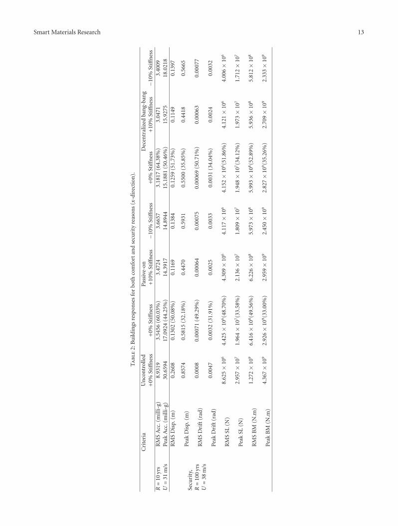
Due to possible changes in the buildings’ natural fre-quencies during its service life [29, 30], uncertainty in thestiffness of the building of ±10% is considered. Table 2 givesthe uncontrolled and controlled responses of the building
in the x-direction. For comfort and security reasons, meanwind speed that corresponds to a return period of 10 yearsand 100 years is used, respectively. For comfort reasons,RMS and peak values of the acceleration are consideredin the comparison. For security, the RMS and the peakvalues of the displacement at the top of the building, theRMS and the peak values of maximum interstory drift,the RMS and the peak values of the shear loads (SL) atthe ground level, and the RMS and the peak values of thebending moment (BM) at the ground level are considered.In the table, “0% stiffness” means the building with theoriginal stiffness, “+10% stiffness” means the building with10% increase in the original stiffness, and “−10% stiffness”means the building with 10% reduction in the originalstiffness. Percentages of response reduction for the case of“0% stiffness” are indicated in the table (between brackets).
Under wind loads with a return period of 10 years, MRdampers with both passive-on and decentralized bang-bangcontroller are able to bring the acceleration responses lowerthan the maximum allowable values (RMS acceleration =5.7 milli-g and peak acceleration = 20 milli-g). However,the decentralized bang-bang controller is shown to workbetter than the passive-on case in reducing the RMSaccelerations for the assumed buildings stiffness uncertainty.This indicates the robustness of the decentralized bang-bang controller. For the building with the original stiffness,decentralized bang-bang controller is able to reduce the RMSand peak accelerations by about 4.4% and 6.2%, respectively.However, for “+10% stiffness” and “−10% stiffness” passive-on is better in reducing the peak accelerations. Under windloads with a return period of 100 years, MR damperswith both passive-on and decentralized bang-bang controllerare capable of reducing the responses of the building.Decentralized bang-bang controller is shown to be betterthan the passive-on in reducing all of the responses except forthe RMS interstory drift angle for the case “−10% stiffness”which is slightly higher than the passive-on case.
5.2.2. Response in the y-Direction. To see the effect of the MRdampers on the responses of the building in the y-direction,a bracing system with an overall deflection of 15 mm isused (about 120 MPa working stress). The responses of thebuilding under the wind attack angle of 0◦ are considered.This wind attack angle was shown to give the highestacceleration and displacement responses in the y-direction[25]. Uncertainty in the stiffness of the building of ±10% isconsidered.
Table 3 gives the uncontrolled and controlled responsesof the building in the y-direction. Under wind loads with areturn period of 10 years, MR dampers with both passive-on and decentralized bang-bang controller are able to bringthe RMS and peak accelerations lower than the maximumallowable values for the assumed uncertainty in the buildingsstiffness except for the “−10% stiffness” with the decentral-ized controller where the peak acceleration is slightly higher.However, this may be accepted as the RMS accelerations aremuch lower than the maximum allowable value (5.7 milli-g). Again, like the x-direction, the decentralized bang-bangcontroller is performing better than the passive-on case
Smart Materials Research 13
Ta
ble
2:B
uild
ings
resp
onse
sfo
rbo
thco
mfo
rtan
dse
curi
tyre
ason
s(x
-dir
ecti
on).
Cri
teri
aU
nco
ntr
olle
dPa
ssiv
e-on
Dec
entr
aliz
edba
ng-
ban
g+
0%St
iffn
ess
+0%
Stiff
nes
s+
10%
Stiff
nes
s−1
0%St
iffn
ess
+0%
Stiff
nes
s+
10%
Stiff
nes
s−1
0%St
iffn
ess
R=
10yr
sR
MS
Acc
.(m
illi-
g)8.
9319
3.54
56(6
0.03
%)
3.47
243.
6657
3.18
17(6
4.38
%)
3.04
713.
4009
U=
31m
/sPe
akA
cc.(
mill
i-g)
30.6
594
17.0
924
(44.
25%
)14
.391
714
.894
415
.188
1(5
0.46
%)
15.9
275
18.0
218
Secu
rity
,R=
100
yrs
U=
38m
/s
RM
SD
isp.
(m)
0.26
080.
1302
(50.
08%
)0.
1169
0.13
840.
1259
(51.
73%
)0.
1149
0.13
97
Peak
Dis
p.(m
)0.
8574
0.58
15(3
2.18
%)
0.44
700.
5931
0.55
00(3
5.85
%)
0.44
180.
5665
RM
SD
rift
(rad
)0.
0008
0.00
071
(49.
29%
)0.
0006
40.
0007
50.
0006
9(5
0.71
%)
0.00
063
0.00
077
Peak
Dri
ft(r
ad)
0.00
470.
0032
(31.
91%
)0.
0025
0.00
330.
0031
(34.
04%
)0.
0024
0.00
32
RM
SSL
(N)
8.62
5×
106
4.42
5×
106(4
8.70
%)
4.30
9×
106
4.11
7×
106
4.15
2×
106(5
1.86
%)
4.12
1×
106
4.00
6×
106
Peak
SL(N
)2.
957×
107
1.96
4×
107(3
3.58
%)
2.13
6×
107
1.80
9×
107
1.94
8×
107(3
4.12
%)
1.97
3×
107
1.71
2×
107
RM
SB
M(N
.m)
1.27
2×
109
6.41
6×
108(4
9.56
%)
6.22
6×
108
5.97
3×
108
5.99
3×
108(5
2.89
%)
5.93
6×
108
5.81
2×
108
Peak
BM
(N.m
)4.
367×
109
2.92
6×
109(3
3.00
%)
2.95
9×
109
2.45
0×
109
2.82
7×
109(3
5.26
%)
2.70
9×
109
2.33
3×
109

14 Smart Materials Research
Ta
ble
3:B
uild
ings
resp
onse
sfo
rbo
thco
mfo
rtan
dse
curi
tyre
ason
s(y
-dir
ecti
on).
Cri
teri
aU
nco
ntr
olle
dPa
ssiv
e-on
Dec
entr
aliz
edba
ng-
ban
g+
0%St
iffn
ess
+0%
Stiff
nes
s+
10%
Stiff
nes
s−1
0%St
iffn
ess
+0%
Stiff
nes
s+
10%
Stiff
nes
s−1
0%St
iffn
ess
R=
10yr
sR
MS
Acc
.(m
g)13
.026
83.
6350
(72.
10%
)3.
4710
3.81
383.
1292
(75.
98%
)2.
9582
3.33
62U
=28
m/s
Peak
Acc
.(m
g)37
.708
716
.162
3(5
7.14
%)
17.1
560
18.4
160
17.9
946
(52.
28%
)16
.119
720
.754
1
Secu
rity
,R=
100
yrs
U=
34.4
m/s
RM
SD
isp.
(m)
0.34
960.
1046
(70.
08%
)0.
0929
0.11
600.
1001
(71.
37%
)0.
0897
0.11
16
Peak
Dis
p.(m
)1.
2290
0.53
81(5
6.22
%)
0.48
540.
5637
0.52
03(5
7.66
%)
0.49
890.
5649
RM
SD
rift
(rad
)0.
0011
0.00
057
(56.
22%
)0.
0005
10.
0006
30.
0005
4(7
1.58
%)
0.00
048
0.00
060
Peak
Dri
ft(r
ad)
0.00
660.
0029
(56.
06%
)0.
0027
0.00
310.
0029
(56.
06%
)0.
0027
0.00
30
RM
SSL
(N)
1.34
7×
107
4.71
1×
106(6
5.03
%)
4.52
12e6
4.80
32e6
4.41
53e6
(67.
22%
)4.
2727
e64.
5132
e6
Peak
SL(N
)4.
864×
107
2.78
4×
107(4
2.76
%)
2.92
53e7
2.12
84e7
2.57
24e7
(47.
11%
)2.
6732
e72.
0441
e7
RM
SB
M(N
.m)
1.99
4×
109
6.53
75e8
(67.
21%
)6.
2312
e86.
6876
e86.
0546
e8(6
9.64
%)
5.80
27e8
6.23
44e8
Peak
BM
(N.m
)6.
873×
109
3.75
9×
109(4
5.31
%)
3.67
94e9
2.95
40e9
3.48
35e9
(49.
32%
)3.
6521
e92.
7948
e9

Smart Materials Research 15
in reducing RMS acceleration values for the building withstiffness uncertainties which indicates the robustness of thiscontroller.
Under wind loads with a return period of 100 years, MRdampers with both passive-on and decentralized bang-bangcontroller are able to give good reductions in the responses ofthe building in the range of 42.76% to 71.56%. Decentralizedbang-bang controller is better than the passive-on in reduc-ing all of the RMS responses. In addition, this controlleris able to reduce the peak shear loads (SLs) and the peakbending moment (BM) over the passive-on case.
6. Concluding Remarks
With many advantages over TMDs and ATMDs, smartdampers are used in this paper to reduce the vibrations ofa tall building in the two lateral directions. Optimization wasdone to find the best position for the MR dampers in thetwo lateral directions. Results show that the best positionof viscous dampers based on drift and modal dampingmaximization is also the best position for the MR damper.Keeping this in mind, one can save a lot of time in runningsimulations with the nonlinear MR damper model.
New bracings-lever mechanism configurations are pro-posed to improve the performance of the dampers. Resultsshow that the proposed control system with the new config-urations is very effective in reducing the capacity and numberof dampers required. It is shown that the decentralizedbang-bang controller with the MR damper may slightlyimprove the performance over the passive-on case for anideal bracing system. Therefore, when the bracings weredesigned to allow for some deformations (practical case), theperformance of the decentralized controller over the passive-on was increased. This means that semiactive controller’seffectiveness is dependent on the stiffness of the bracingsystem. However, the methodology developed in this paperpermits the acceleration levels and design forces of tallbuildings under winds to be controlled and assessed at thepreliminary design stages.
The contributions of this paper can be summarized asfollows.
(1) For the purpose of using MR dampers for vibrationreduction in buildings, it is recognized that shearresponse and flexural response of tall buildingspresent two very different cases for vibration suppres-sion.
(2) A lever mechanism can enable application to flexuralresponse and scenarios where the interstory drift isnot enough for dampers to work effectively.
(3) A comparison of on/off control to full-time applica-tion may be insightful.
In spite of the great advantages of MR dampers overTMDs and ATMDs, the outer bracings in the y-directionmay not be generalized for similar tall buildings if there isspace limitation. In such case, ATMD is a possible alternative.Nevertheless, the proposed control system in the x-directionis an excellent choice.
References
[1] T. T. Soong, Active Structural Control: Theory and Practice,John Wiley & Sons, 1990.
[2] J. C. Wu and B. C. Pan, “Wind tunnel verification of activelycontrolled high-rise building in along-wind motion,” Journalof Wind Engineering and Industrial Aerodynamics, vol. 90, no.12–15, pp. 1933–1950, 2002.
[3] L. T. Lu, W. L. Chiang, J. P. Tang, M. Y. Liu, and C.W. Chen, “Active control for a benchmark building underwind excitations,” Journal of Wind Engineering and IndustrialAerodynamics, vol. 91, no. 4, pp. 469–493, 2003.
[4] A. M. Aly, F. Resta, and A. Zasso, “Active control in a high-risebuilding under multidirectional wind loads,” in Proceedingsof the Structures Congress, vol. 314, Vancouver, Canada, April2008.
[5] A. M. Aly, A. Zasso, and F. Resta, “Dynamics and control ofhigh-rise buildings under multidirectional wind loads,” SmartMaterials Research, vol. 2011, Article ID 549621, 15 pages,2011.
[6] R. J. Smith and M. R. Willford, “The damped outriggerconcept for tall buildings,” Structural Design of Tall and SpecialBuildings, vol. 16, no. 4, pp. 501–517, 2007.
[7] S. J. Dyke, B. F. Spencer, M. K. Sain, and J. D. Carlson,“Modeling and control of magnetorheological dampers forseismic response reduction,” Smart Materials and Structures,vol. 5, no. 5, pp. 565–575, 1996.
[8] H. Metwally, B. El-Souhily, and A. Aly, “Reducing vibrationeffects on buildings due to earthquake using magneto-rheological dampers,” AEJ - Alexandria Engineering Journal,vol. 45, no. 2, pp. 131–140, 2006.
[9] A. M. Aly and R. E. Christenson, “On the evaluation of theefficacy of a smart damper: a new equivalent energy-basedprobabilistic approach,” Smart Materials and Structures, vol.17, no. 4, Article ID 045008, 2008.
[10] A. M. Aly, A. Zasso, and F. Resta, “On the dynamics of a veryslender building under winds: response reduction using MRdampers with lever mechanism,” Structural Design of Tall andSpecial Buildings, vol. 20, no. 5, pp. 539–551, 2011.
[11] M. C. Constantinou, P. Tsopelas, and W. Hammel, “Testingand modeling of an improved damper configuration for stiffstructural systems,” Tech. Rep., Center for Industrial Effective-ness and Taylor Devices, 1998.
[12] C. H. Huang, “Parametric study for motion amplification de-vice with viscous damper,” in the 13th World Conference onEarthquake Engineering, Vancouver, Canada, 2004.
[13] R. J. McNamara and D. P. Taylor, “Fluid viscous dampersfor high-rise buildings,” Structural Design of Tall and SpecialBuildings, vol. 12, no. 2, pp. 145–154, 2003.
[14] A. N. Sigaher and M. C. Constantinou, “Scissor-jack-damperenergy dissipation system,” Earthquake Spectra, vol. 19, no. 1,pp. 133–158, 2003.
[15] S. Berton and J. E. Bolander, “Amplification system for sup-plemental damping devices in seismic applications,” Journal ofStructural Engineering, vol. 131, no. 6, pp. 979–983, 2005.
[16] S.-H. Lee, K.-W. Min, L. Chung et al., “Bracing systems forinstallation of MR dampers in a building structure,” Journal ofIntelligent Material Systems and Structures, vol. 18, no. 11, pp.1111–1120, 2007.
[17] K. K. Walsh, K. J. Cronin, M. D. Rambo-Roddenberry, and K.Grupenhof, “Dynamic analysis of seismically excited flexible

16 Smart Materials Research
truss tower with scissor-jack dampers,” Structural Control andHealth Monitoring. In press.
[18] N. Satake, K. I. Suda, T. Arakawa, A. Sasaki, and Y. Tamura,“Damping evaluation using full-scale data of buildings inJapan,” Journal of Structural Engineering, vol. 129, no. 4, pp.470–477, 2003.
[19] Y. Tamura and A. Yoshida, “Amplitude dependency of damp-ing in buildings,” in Proceedings of the 18th Analysis and Com-putation Speciality Conference, vol. 315, Vancouver, Canada,April 2008.
[20] S. Attaway, Matlab: A Practical Introduction to Programmingand Problem Solving, Butterworth-Heinemann, Amsterdam,The Netherlands, 2009.
[21] I. Chowdhury and S. P. Dasgupta, “Computation of Rayleighdamping coefficients for large systems,” Electronic Journal ofGeotechnical Engineering, vol. 8, 2003.
[22] L. Meirovitch, Analytical Methods in Vibrations, The Macmil-lan Co., New York, NY, USA, 1967.
[23] G. Diana, S. De Ponte, M. Falco, and A. Zasso, “A newlarge wind tunnel for civil-environmental and aeronauticalapplications,” Journal of Wind Engineering and IndustrialAerodynamics, vol. 74–76, pp. 553–565, 1998.
[24] Eurocode 1, “Eurocode 1: Actions on structures—Generalactions — Part 1-4: Wind actions,” prEN 1991-1-4: EuropeanStandard, 2004.
[25] A. M. Aly, On the dynamics of buildings under winds andearthquakes: response prediction and reduction, Ph.D. the-sis, Department of Mechanical Engineering, Politecnico diMilano, Milan, Italy, 2009.
[26] F. Yi, S. J. Dyke, J. M. Caicedo, and J. D. Carlson, “Seismicresponse control using smart dampers,” in Proceedings of theAmerican Control Conference (ACC ’99), pp. 1022–1026, June1999.
[27] A. Khaje-Karamodin, H. Haji-Kazemi, A. R. Rowhanimanesh,and M. R. Akbarzadeh-Tootoonchi, “Semi-active control ofstructures using a neuro-inverse model of MR dampers,”Scientia Iranica, vol. 16, no. 3, pp. 256–263, 2009.
[28] S. J. Dyke and B. F. Spencer Jr., “A comparison of semi-activecontrol strategies for the MR damper,” in Proceedings of theIASTED International Conference on Intelligent InformationSystems (IIS ’97), Grand Bahama Island, Bahamas, December1997.
[29] K. V. Yuen and S. C. Kuok, “Ambient interference in long-termmonitoring of buildings,” Engineering Structures, vol. 32, no. 8,pp. 2379–2386, 2010.
[30] K. V. Yuen and S. C. Kuok, “Modeling of environmental influ-ence in structural health assessment for reinforced concretebuildings,” Earthquake Engineering and Engineering Vibration,vol. 9, no. 2, pp. 295–306, 2010.

Submit your manuscripts athttp://www.hindawi.com
ScientificaHindawi Publishing Corporationhttp://www.hindawi.com Volume 2014
CorrosionInternational Journal of
Hindawi Publishing Corporationhttp://www.hindawi.com Volume 2014
Polymer ScienceInternational Journal of
Hindawi Publishing Corporationhttp://www.hindawi.com Volume 2014
Hindawi Publishing Corporationhttp://www.hindawi.com Volume 2014
CeramicsJournal of
Hindawi Publishing Corporationhttp://www.hindawi.com Volume 2014
CompositesJournal of
NanoparticlesJournal of
Hindawi Publishing Corporationhttp://www.hindawi.com Volume 2014
Hindawi Publishing Corporationhttp://www.hindawi.com Volume 2014
International Journal of
Biomaterials
Hindawi Publishing Corporationhttp://www.hindawi.com Volume 2014
NanoscienceJournal of
TextilesHindawi Publishing Corporation http://www.hindawi.com Volume 2014
Journal of
NanotechnologyHindawi Publishing Corporationhttp://www.hindawi.com Volume 2014
Journal of
CrystallographyJournal of
Hindawi Publishing Corporationhttp://www.hindawi.com Volume 2014
The Scientific World JournalHindawi Publishing Corporation http://www.hindawi.com Volume 2014
Hindawi Publishing Corporationhttp://www.hindawi.com Volume 2014
CoatingsJournal of
Advances in
Materials Science and EngineeringHindawi Publishing Corporationhttp://www.hindawi.com Volume 2014
Smart Materials Research
Hindawi Publishing Corporationhttp://www.hindawi.com Volume 2014
Hindawi Publishing Corporationhttp://www.hindawi.com Volume 2014
MetallurgyJournal of
Hindawi Publishing Corporationhttp://www.hindawi.com Volume 2014
BioMed Research International
MaterialsJournal of
Hindawi Publishing Corporationhttp://www.hindawi.com Volume 2014
Nano
materials
Hindawi Publishing Corporationhttp://www.hindawi.com Volume 2014
Journal ofNanomaterials