proportional pressure relief valve, direct ... - bosch...
TRANSCRIPT
1/14
Information on available spare parts:www.boschrexroth.com/spc
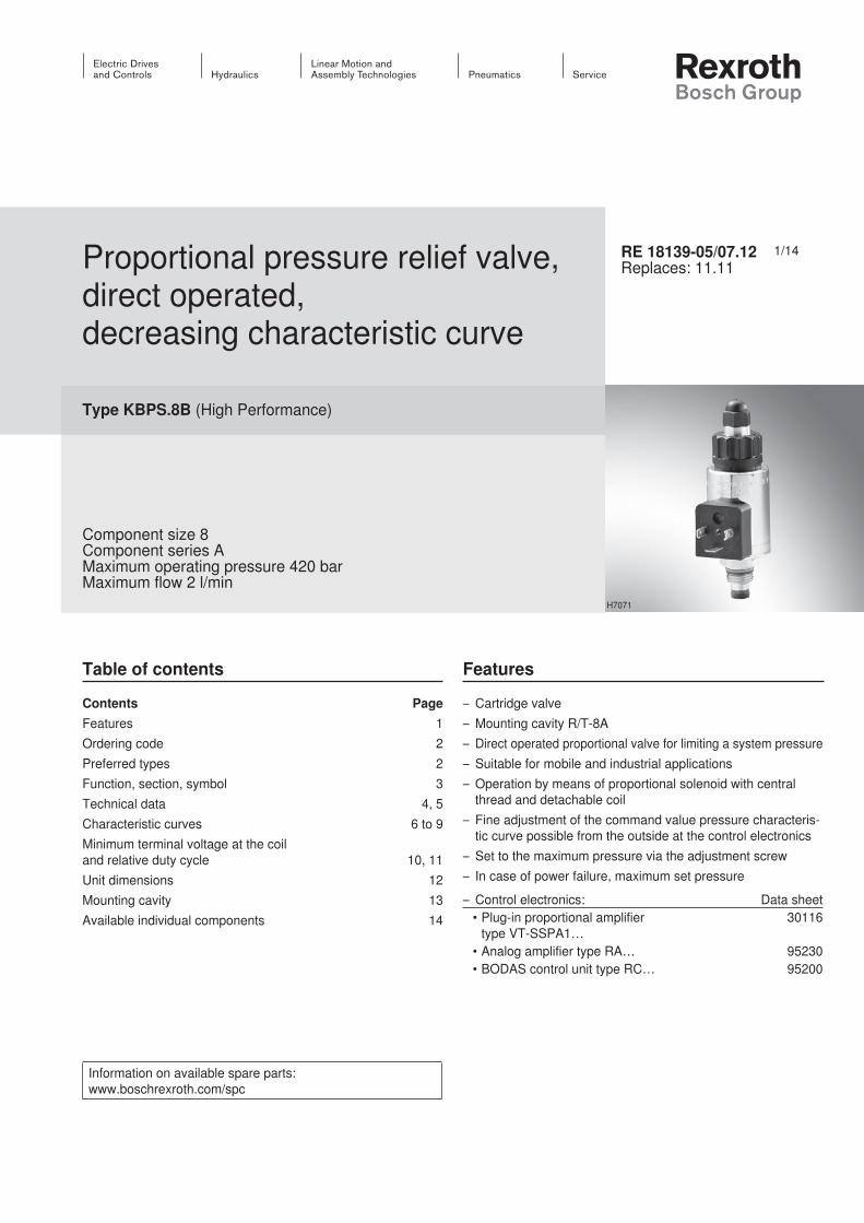
Proportional pressure relief valve, direct operated, decreasing characteristic curve
Type KBPS.8B (High Performance)
Component size 8Component series AMaximum operating pressure 420 barMaximum flow 2 l/min
RE 18139-05/07.12Replaces: 11.11
Table of contents Features
H7071
Contents PageFeatures 1Ordering code 2Preferred types 2Function, section, symbol 3Technical data 4, 5Characteristic curves 6 to 9Minimum terminal voltage at the coil and relative duty cycle 10, 11Unit dimensions 12Mounting cavity 13Available individual components 14
– Cartridge valve– Mounting cavity R/T-8A– Direct operated proportional valve for limiting a system pressure– Suitable for mobile and industrial applications – Operation by means of proportional solenoid with central
thread and detachable coil– Fine adjustment of the command value pressure characteris-
tic curve possible from the outside at the control electronics– Set to the maximum pressure via the adjustment screw– In case of power failure, maximum set pressure
– Control electronics: Data sheet• Plug-in proportional amplifier
type VT-SSPA1…30116
• Analog amplifier type RA… 95230• BODAS control unit type RC… 95200
2/14 Bosch Rexroth AG Hydraulics KBPS RE 18139-05/07.12
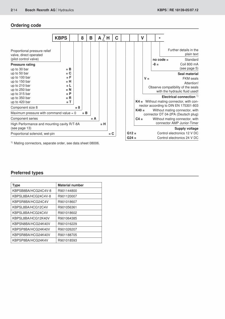
Ordering code
Preferred types
Type Material numberKBPSB8BA/HCG24C4V-8 R901144800KBPSL8BA/HCG24C4V-8 R901120007KBPSR8BA/HCG24C4V R901018607KBPSL8BA/HCG12C4V R901056361KBPSL8BA/HCG24C4V R901018602KBPSL8BA/HCG12K40V R901064385KBPSN8BA/HCG24K40V R901016229KBPSP8BA/HCG24K40V R901026207KBPSR8BA/HCG24K40V R901188705KBPSP8BA/HCG24K4V R901018593
Proportional pressure relief valve, direct operated(pilot control valve)
Pressure ratingup to 30 bar = Bup to 50 bar = Cup to 100 bar = Fup to 150 bar = Hup to 210 bar = Lup to 250 bar = Nup to 315 bar = Pup to 350 bar = Rup to 420 bar = TComponent size 8 = 8Maximum pressure with command value = 0 = BComponent series = AHigh Performance and mounting cavity R/T-8A = H(see page 13)Proportional solenoid, wet-pin = C
Further details in the plain text
no code = Standard-8 = Coil 800 mA
(see page 5)Seal material
V = FKM seals Attention!
Obs erve compati bili ty of the seals with the hydrau lic flu id used!
Electrical connection 1)
K4 = Without mating connector, with con-nector according to DIN EN 175301-803
K40 = Without mating connector, with connector DT 04-2PA (Deutsch plug)
C4 = Without mating connector, with connector AMP Junior-Timer
Supply voltage G12 = Control electronics 12 V DC G24 = Control electronics 24 V DC
KBPS 8 B A H C V *
1) Mating connectors, separate order, see data sheet 08006.
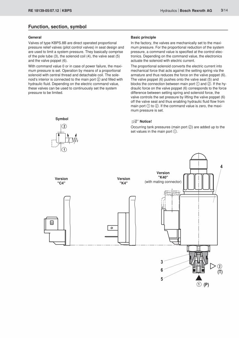
3
5
6 (T)
(P)
2
1
4
2
1
Hydraulics Bosch Rexroth AGRE 18139-05/07.12 KBPS 3/14
Function, section, symbol
Symbol
GeneralValves of type KBPS.8B are direct operated proportional pressure relief valves (pilot control valves) in seat design and are used to limit a system pressure. They basically comprise of the pole tube (3), the solenoid coil (4), the valve seat (5) and the valve poppet (6).With command value 0 or in case of power failure, the maxi-mum pressure is set. Operation by means of a proportional solenoid with central thread and detachable coil. The sole-noid‘s interior is connected to the main port ② and filled with hydraulic fluid. Depending on the electric command value, these valves can be used to continuously set the system pressure to be limited.
Basic principleIn the factory, the valves are mechanically set to the maxi-mum pressure. For the proportional reduction of the system pressure, a command value is specified at the control elec-tronics. Depending on the command value, the electronics actuate the solenoid with electric current.The proportional solenoid converts the electric current into mechanical force that acts against the setting spring via the armature and thus reduces the force on the valve poppet (6). The valve poppet (6) pushes onto the valve seat (5) and blocks the connection between main port ① and ②. If the hy-draulic force on the valve poppet (6) corresponds to the force difference between setting spring and solenoid force, the valve controls the set pressure by lifting the valve poppet (6) off the valve seat and thus enabling hydraulic fluid flow from main port ① to ②. If the command value is zero, the maxi-mum pressure is set.
Notice!Occurring tank pressures (main port ②) are added up to the set values in the main port ①.
Version"C4"
Version"K40"
(with mating connector)Version
"K4"

4/14 Bosch Rexroth AG Hydraulics KBPS RE 18139-05/07.12
Technical data (For applications outside these parameters, please consult us!)
generalWeight kg 0.45Installation position Any - if it is ensured that no air can collect upstream the
valve. Otherwise, we recommend suspended installation of the valve.
Ambient temperature range °C –20 to +120Storage temperature range °C –20 to +80
Environmental audits:Vibration test according to DIN EN 60068-2 / IEC 60068-2 /2 axes (X/Z)DIN EN 60068-2-6: 05/96 Vibrations, sine-shaped 10 cycles (5 Hz to 2000 Hz back to 5 Hz) with logarithmic
frequency changing speed of 1 octave/min, 5 to 57 Hz, ampli-tude 1.5 mm (p-p), 57 to 2000 Hz, amplitude 10 g
IEC 60068-2-64: 05/93 Vibrations (random) andbroadband noise
20 to 2000 Hz, amplitude 0.05 g2/Hz(10 g RMS/30 g peak), testing time 30 min
DIN EN 60068-2-27: 03/95 Shocking Half sine 15 g / 11 ms, 3 x in positive, 3 x in negative direc-tion (a total of 6 individual shocks)
DIN EN 60068-2-29: 03/95 Bump test Half sine 25 g / 6 ms, 1000 x in positive, 1000 x in negative direction (a total of 2000 individual shocks)
Indication per axisClimatic test according to EN 60068-2 / IEC 60068-2 (environmental test):DIN EN 60068-2-1: 03/95 Storage temperature –40 °C, duration 16 hDIN EN 60068-2-2: 08/94 +110 °C, duration 16 hDIN EN 60068-2-1: 03/95 Cold test 2 cycles –25 °C, duration 2 hDIN EN 60068-2-2: 08/94 Dry heating test 2 cycles +120 °C, duration 2 hIEC 60068-2-30: 1985 Humid heat, cyclic Variant 2/ +25 °C to +55 °C
93 % to 97 % relative humidity, 2 cycles à 24 hSalt spray test: 720 h according to DIN 50021→ Coating generally not necessary. If paint is applied nevertheless, the reduced heat dissipation capacity is to be observed.
hydraulicMaximum operating pressure 1) (main port ①) bar 420Maximum admissible return flow pressure (main port ②)
bar 210
Maximum set pressure 2) See command value pressure characteristic curves page 6Minimum set pressure with command value max 3) See characteristic curves page 8 and 9Maximum flow l/min 2 (see characteristic curves page 6 and 7)Hydraulic fluid See page 5Hydraulic fluid temperature range °C –20 to +80Viscosity range mm2/s 15 to 380Maximum permitted degree of contamination of the hydraulic fluid - cleanliness class according to ISO 4406 (c)
Class 20/18/15 4)
1) Attention! The maximum operating pressure is the total of set pressure and return flow pressure!
2) Attention! The valves are set in the factory. In case of subsequent adjustment, the warranty will become invalid!
3) If the valve is installed in a mounting cavity made of non-magnetically conductive material, the minimum set pres-sure is slightly higher.
4) The cleanliness classes specified for the components must be adhered to in hydraulic systems. Effective filtration pre-vents faults and at the same time increases the service life of the components.
For the selection of the filters see www.boschrexroth.com/filter.
Hydraulics Bosch Rexroth AGRE 18139-05/07.12 KBPS 5/14
Technical data (For applications outside these parameters, please consult us!)
hydraulicHysteresis 5) < 4 % of the max. set pressure Range of inversion 5) < 0.5 % of the max. set pressure Response sensitivity 5) < 0.5 % of the max. set pressure Manufacturing tolerance of the command value pressure characteristic curve
– Command value 100 % < 2 % of the max. set pressure
– Command value 0 < 5 % of the max. set pressure
Step response (Tu + Tg) 0 → 100 % and/or 100 % → 0 ms 70 (depending on the system)
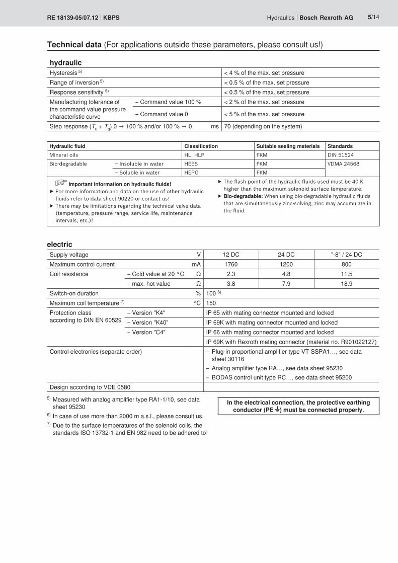
electricSupply voltage V 12 DC 24 DC "-8" / 24 DCMaximum control current mA 1760 1200 800Coil resistance – Cold value at 20 °C Ω 2.3 4.8 11.5
– max. hot value Ω 3.8 7.9 18.9Switch-on duration % 100 6)
Maximum coil temperature 7) °C 150Protection class according to DIN EN 60529
– Version "K4" IP 65 with mating connector mounted and locked– Version "K40" IP 69K with mating connector mounted and locked– Version "C4" IP 66 with mating connector mounted and locked
IP 69K with Rexroth mating connector (material no. R901022127)Control electronics (separate order) – Plug-in proportional amplifier type VT-SSPA1…, see data
sheet 30116– Analog amplifier type RA…, see data sheet 95230– BODAS control unit type RC…, see data sheet 95200
Design according to VDE 05805) Measured with analog amplifier type RA1-1/10, see data
sheet 952306) In case of use more than 2000 m a.s.l., please consult us.7) Due to the surface temperatures of the solenoid coils, the
standards ISO 13732-1 and EN 982 need to be adhered to!
In the electrical connection, the protective earthing conductor (PE ) must be connected pro per ly.
Hydraulic fluid Classification Suitable sealing materials StandardsMineral oils HL, HLP FKM DIN 51524
Bio-degradable – Insoluble in water HEES FKM VDMA 24568
– Soluble in water HEPG FKM
Important information on hydraulic fluids! ▶ For more information and data on the use of other hydraulic fluids refer to data sheet 90220 or contact us!
▶ There may be limitations regarding the technical valve data (temperature, pressure range, service life, maintenance intervals, etc.)!
▶ The flash point of the hydraulic fluids used must be 40 K higher than the maximum solenoid surface temperature.
▶ Bio-degradable: When using bio-degradable hydraulic fl uids that are simultaneously zinc-solving, zinc may accumulate in the fluid.
���
���
���
��
� �� �� �� ���
���
� ��� �� ��� �� ���
��
��
��
��
� ��� �� ��� �� ���
��
�
��
��
���
���
��
�
���
���
������
������
��
� �� �� �� ���
���
���
���
� ��� �� ��� �� ���
��
�
���
��
�
���
� ��� �� ��� �� ���
��
��
��
�
��
��
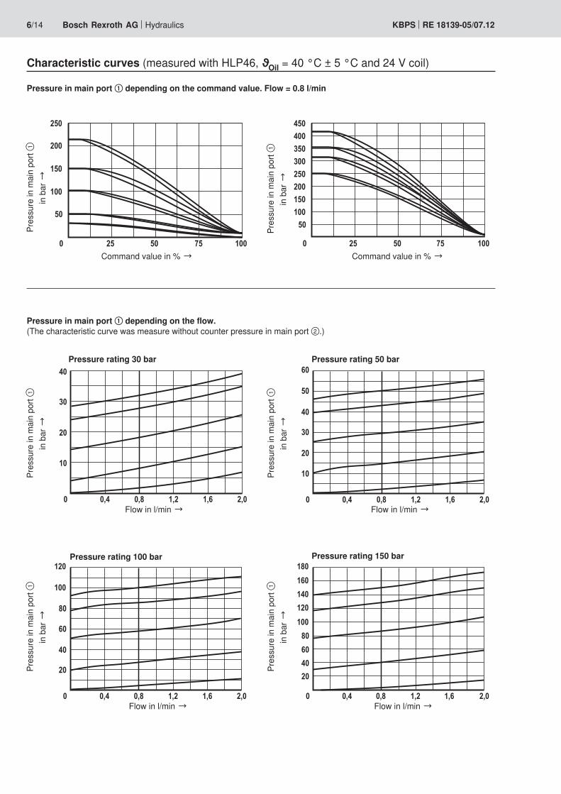
6/14 Bosch Rexroth AG Hydraulics KBPS RE 18139-05/07.12
Characteristic curves (measured with HLP46, ϑOil = 40 °C ± 5 °C and 24 V coil)
Command value in % →
Pressure in main port ① depending on the command value. Flow = 0.8 l/min
Pres
sure
in m
ain
port
①
in b
ar →
Flow in l/min →
Pressure rating 30 bar
Pres
sure
in m
ain
port
①
in b
ar →
Pres
sure
in m
ain
port
①
in b
ar →
Pres
sure
in m
ain
port
①
in b
ar →
Pres
sure
in m
ain
port
①
in b
ar →
Flow in l/min →
Pressure rating 150 bar
Pressure in main port ① depending on the flow. (The characteristic curve was measure without coun ter pressure in main port ②.)
Command value in % →Pr
essu
re in
mai
n po
rt ①
in
bar
→
Flow in l/min →
Pressure rating 100 bar
Flow in l/min →
Pressure rating 50 bar

� ��� �� ��� �� ���
��
���
���
�
���
������
��
��
���
� ��� �� ��� �� ���
���
���
���
���
���
���
���
��
� ��� �� ��� �� ���
���
���
���
���
���
��
�
��
��
��
� ��� �� ��� �� ���
�
��
��
���
���
���
��
� ��� �� ��� �� ���
���
���
���
���
�����
�
��
��
��
�����
Hydraulics Bosch Rexroth AGRE 18139-05/07.12 KBPS 7/14
Characteristic curves (measured with HLP46, ϑOil = 40 °C ± 5 °C and 24 V coil)
Flow in l/min →
Pressure rating 250 bar
Flow in l/min →
Pressure rating 350 bar
Flow in l/min →
Pressure rating 315 bar
Pressure in main port ① depending on the flow. (The characteristic curve was measure without coun ter pressure in main port ②.)
Flow in l/min →
Pressure rating 210 bar
Flow in l/min →
Pressure rating 420 bar
Pres
sure
in m
ain
port
①
in b
ar →
Pres
sure
in m
ain
port
①
in b
ar →
Pres
sure
in m
ain
port
①
in b
ar →
Pres
sure
in m
ain
port
①
in b
ar →
Pres
sure
in m
ain
port
①
in b
ar →
� ��� �� ��� �� ���
�
��
��
�
�
��
� ��� �� ��� �� ���
�
�
�
��
��
��
� ��� �� ��� �� ���
�
��
�
��
���
��
�
� ��� �� ��� �� ���
�
�
�
�
� ��� �� ��� �� ���
��
�
�
��
� ��� �� ��� �� ���
�
�
�
�
�
�
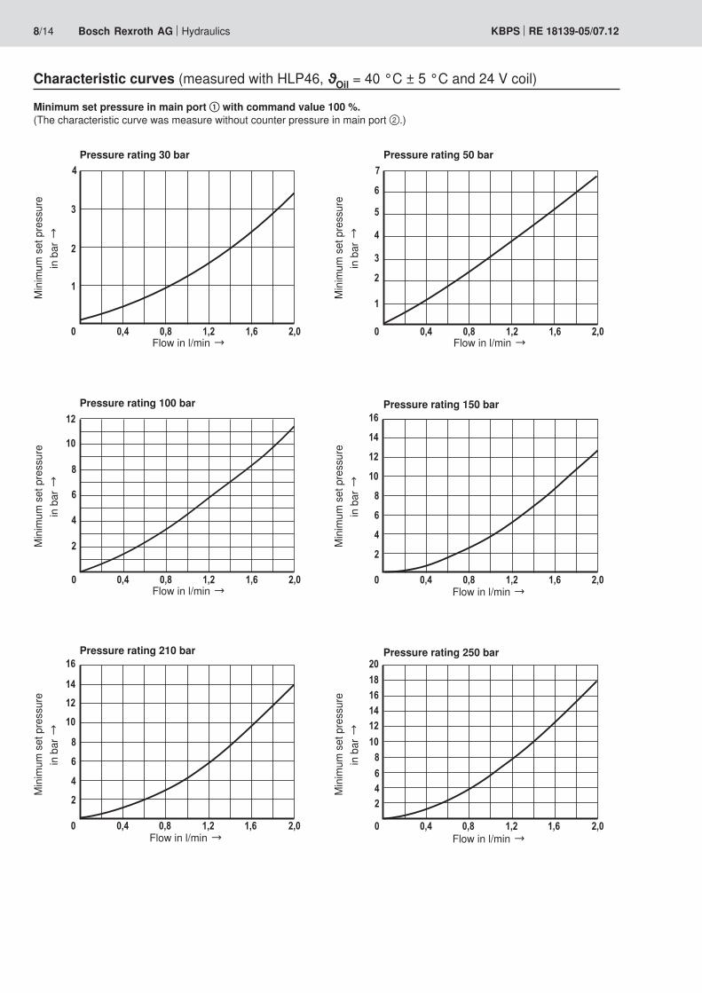
8/14 Bosch Rexroth AG Hydraulics KBPS RE 18139-05/07.12
Characteristic curves (measured with HLP46, ϑOil = 40 °C ± 5 °C and 24 V coil)
Flow in l/min →
Pressure rating 150 bar
Flow in l/min →
Pressure rating 210 bar
Flow in l/min →
Pressure rating 250 bar
Minimum set pressure in main port ① with command value 100 %. (The characteristic curve was measure without coun ter pressure in main port ②.)
Flow in l/min →
Pressure rating 30 bar
Flow in l/min →
Pressure rating 100 bar
Flow in l/min →
Pressure rating 50 bar
Min
imum
set
pre
ssur
e in
bar
→
Min
imum
set
pre
ssur
e in
bar
→
Min
imum
set
pre
ssur
e in
bar
→
Min
imum
set
pre
ssur
e in
bar
→
Min
imum
set
pre
ssur
e in
bar
→
Min
imum
set
pre
ssur
e in
bar
→
� ��� �� ��� �� ���
�
��
��
��
��
� ��� �� ��� �� ���
�
��
��
��
��
� ��� �� ��� �� ���
�
��
��
��
��
��
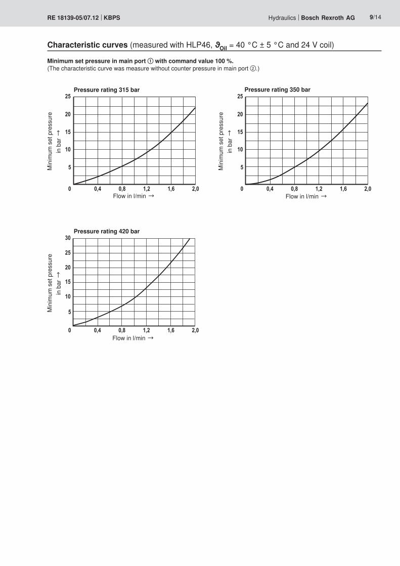
Hydraulics Bosch Rexroth AGRE 18139-05/07.12 KBPS 9/14
Flow in l/min →
Pressure rating 315 bar
Flow in l/min →
Pressure rating 350 bar
Flow in l/min →
Pressure rating 420 bar
Characteristic curves (measured with HLP46, ϑOil = 40 °C ± 5 °C and 24 V coil)
Minimum set pressure in main port ① with command value 100 %. (The characteristic curve was measure without coun ter pressure in main port ②.)
Min
imum
set
pre
ssur
e in
bar
→M
inim
um s
et p
ress
ure
in b
ar →
Min
imum
set
pre
ssur
e in
bar
→
���
�� � �� �����
���
�
���
�
���
��
�
�����
�
�
��
��
���
���
���
���
� �����
���
����
��
���
���
����
��
���
�
�
�
���
�� � �� �����
�
�
�
��
�����
�
�
��
��
���
���
� ��
����
���
����
���
����
���
�
�
�
10/14 Bosch Rexroth AG Hydraulics KBPS RE 18139-05/07.12
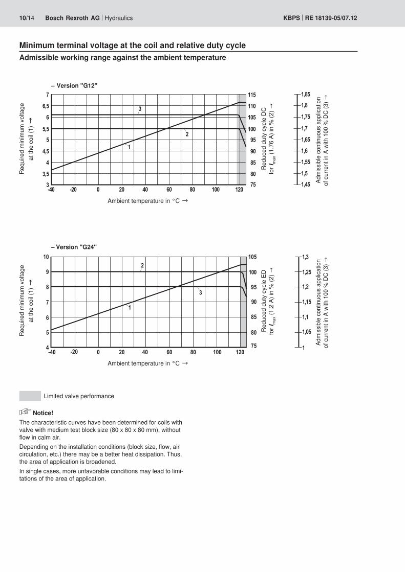
Minimum terminal voltage at the coil and relative duty cycle
Ambient temperature in °C →
Ambient temperature in °C →
Requ
ired
min
imum
vol
tage
at
the
coil (
1) →
Requ
ired
min
imum
vol
tage
at
the
coil (
1) →
Redu
ced
duty
cyc
le D
C fo
r Im
ax (1
.76
A) in
% (2
) →Re
duce
d du
ty c
ycle
ED
for I
max
(1.2
A) i
n %
(2) →
Adm
issib
le c
ontin
uous
app
licat
ion
of c
urre
nt in
A w
ith 1
00 %
DC
(3) →
Adm
issib
le c
ontin
uous
app
licat
ion
of c
urre
nt in
A w
ith 1
00 %
DC
(3) →
– Version "G12"
– Version "G24"
Admissible working range against the ambient temperature
Limited valve performance
Notice!The characteristic curves have been determined for coils with valve with medium test block size (80 x 80 x 80 mm), without flow in calm air.Depending on the installation conditions (block size, flow, air circulation, etc.) there may be a better heat dissipation. Thus, the area of application is broadened.In single cases, more unfavorable conditions may lead to limi-tations of the area of application.
���
�� � �� �����
��
��
��
�
�����
�
�
��
��
���
���
� ����
���
����
��
���
���
����
�
�
�
Hydraulics Bosch Rexroth AGRE 18139-05/07.12 KBPS 11/14
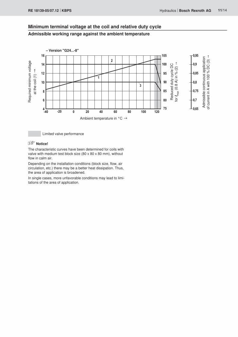
Minimum terminal voltage at the coil and relative duty cycle
Ambient temperature in °C →
Requ
ired
min
imum
vol
tage
at
the
coil (
1) →
Redu
ced
duty
cyc
le D
C fo
r Im
ax (0
.8 A
) in
% (2
) →
Adm
issib
le c
ontin
uous
app
licat
ion
of c
urre
nt in
A w
ith 1
00 %
DC
(3) →
– Version "G24...-8"
Admissible working range against the ambient temperature
Limited valve performance
Notice!The characteristic curves have been determined for coils with valve with medium test block size (80 x 80 x 80 mm), without flow in calm air.Depending on the installation conditions (block size, flow, air circulation, etc.) there may be a better heat dissipation. Thus, the area of application is broadened.In single cases, more unfavorable conditions may lead to limi-tations of the area of application.
�
�
��
�� ��
���
�
��
�
�
�
���
��
���
12/14 Bosch Rexroth AG Hydraulics KBPS RE 18139-05/07.12
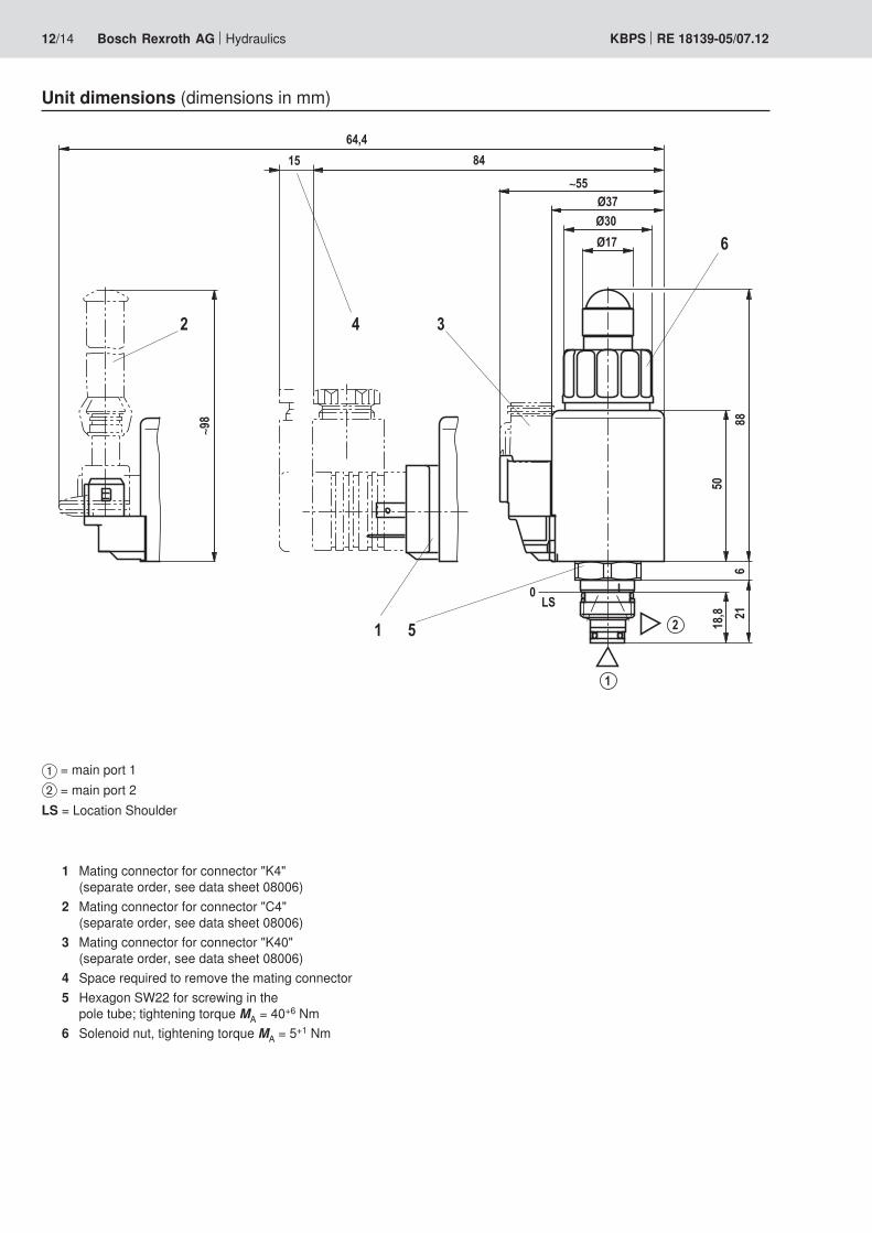
Unit dimensions (dimensions in mm)
1 Mating connector for connector "K4" (separate order, see data sheet 08006)
2 Mating connector for connector "C4" (separate order, see data sheet 08006)
3 Mating connector for connector "K40"(separate order, see data sheet 08006)
4 Space required to remove the ma ting connec tor5 Hexagon SW22 for screwing in the
pole tube; tightening torque MA = 40+6 Nm6 Solenoid nut, tightening torque MA = 5+1 Nm
1 = main port 12 = main port 2
LS = Location Shoulder
��������
����������� �����
� ������ �
�������
���������
� ������
���
���
����
����
����
����
�
� ��
�������
����������
����������
�����
���������� ������
���������
���
��
���
���
����
����
���
����
�
�
��!
�����"#$
"%$
"%$
�����
�����
� �����
��&��
� ������
�����������
"#$
���������
�����
�������&�� ��&
� ������
��� ����������
�
� ������
Hydraulics Bosch Rexroth AGRE 18139-05/07.12 KBPS 13/14
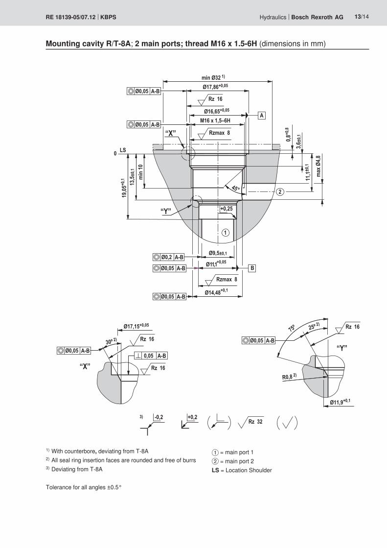
Mounting cavity R/T-8A; 2 main ports; thread M16 x 1.5-6H (dimensions in mm)
1) With counterbore, deviating from T-8A2) All seal ring insertion faces are rounded and free of burrs3) Deviating from T-8A
Tolerance for all angles ±0.5°
1 = main port 12 = main port 2
LS = Location Shoulder
Bosch Rexroth AGHydraulicsZum Eisengießer 197816 Lohr am Main, GermanyPhone +49 (0) 93 52 / [email protected]
© This document, as well as the data, specifications and other informa-tion set forth in it, are the exclusive property of Bosch Rexroth AG. It may not be reproduced or given to third parties without its consent.The data specified above only serve to describe the product. No state-ments concerning a certain condition or suitability for a certain applica-tion can be derived from our information. The information given does not release the user from the obligation of own judgment and verification. It must be remembered that our products are subject to a natural process of wear and aging.
14/14 Bosch Rexroth AG Hydraulics KBPS RE 18139-05/07.12
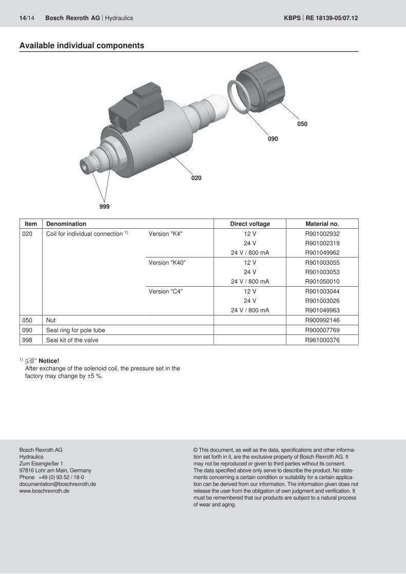
Available individual components
1) Notice!After exchange of the solenoid coil, the pressure set in the factory may change by ±5 %.
Item Denomination Direct voltage Material no.020 Coil for individual connection 1) Version "K4" 12 V
24 V24 V / 800 mA
R901002932R901002319R901049962
Version "K40" 12 V24 V
24 V / 800 mA
R901003055R901003053R901050010
Version "C4" 12 V24 V
24 V / 800 mA
R901003044R901003026R901049963
050 Nut R900992146090 Seal ring for pole tube R900007769998 Seal kit of the valve R961000376
999
020
090
050

Bosch Rexroth AGHydraulicsZum Eisengießer 197816 Lohr am Main, GermanyPhone +49 (0) 93 52 / [email protected]
© This document, as well as the data, specifications and other informa-tion set forth in it, are the exclusive property of Bosch Rexroth AG. It may not be reproduced or given to third parties without its consent.The data specified above only serve to describe the product. No state-ments concerning a certain condition or suitability for a certain applica-tion can be derived from our information. The information given does not release the user from the obligation of own judgment and verification. It must be remembered that our products are subject to a natural process of wear and aging.
Hydraulics Bosch Rexroth AGRE 18139-05/07.12 KBPS 15/14
Notes

Bosch Rexroth AGHydraulicsZum Eisengießer 197816 Lohr am Main, GermanyPhone +49 (0) 93 52 / [email protected]
© This document, as well as the data, specifications and other informa-tion set forth in it, are the exclusive property of Bosch Rexroth AG. It may not be reproduced or given to third parties without its consent.The data specified above only serve to describe the product. No state-ments concerning a certain condition or suitability for a certain applica-tion can be derived from our information. The information given does not release the user from the obligation of own judgment and verification. It must be remembered that our products are subject to a natural process of wear and aging.
16/14 Bosch Rexroth AG Hydraulics KBPS RE 18139-05/07.12
Notes