properties and performance of cement- based grouts …
TRANSCRIPT

BNL- 67006
INFORMAL REPORT
PROPERTIES AND PERFORMANCE OF CEMENT- BASED GROUTS FOR GEOTHERMAL HEAT
PUMP APPLICATIONS
FINAL REPORT FY 1999
M.L. Allan and A.J. Philippacopoulos
November 1999
Prepared for: Office of Geothermal Technologies United States Department of Energy Washington, DC 20585
Materials and Chemical Sciences Division

DISCLAIMER
This document was prepared as an account of work sponsored by an agenc:y of the United States Government. Neither the United States Government nor any agency thereof, nor any of their employees, nor any of their contractors, subcontractors, or their employees makers any warranty, express or implied, or assumes any legal liability or responsibility of the accuracy, completeness, or usefulness of any information, apparatus, product or process disclosed, or represents that its use would not infringe privately owned rights. Reference herein to any specific commercial product, process, or service by trade name, trademark, manufacturer, or otherwise, does not necessarily constitute or imply its endorsement, recommendation, or favoring by the United States Government or any agency thereof. The views and opinions of authors expressed herein do not necessarily state or reflect the United States Government or any agency, contractor, or subcontractor thereof.

PROPERTIES AND PERFORMANCE OF CEMENT-BASED GROUTS FOR GEOTHERMAL HEAT PUMP APPLtICATIONS:
FINAL REPORT FY 99
M.L. ALLAN and A.J. PHILIPPACOPOULOS
NOVEMBER 1999
Prepared for: Office of Geothermal Technologies
U.S. Department of Energy 1000 Independence Ave., S.W.
Washington, D.C. 20585
Materials and Chemical Sciences Division Department of Applied Science
Brookhaven National Laboratory Upton, New York 11973-5000
This work was performed under the auspices of the 1J.S. Department of Energy, Washington, D.C., under Contract No. DE-AC02-98CH10886.


CONTENTS
Page
Summary ......................................................................................................................................... .v
Acknowledgements.. ..................................................................................................................... vii
1.0
2.0
3.0
4.0
5.0
6.0
7.0
8.0
Introduction.. ........................................................................................................................ 1
Experimental Procedure.. .................................................................................................... .2
2.1 Materials and Mix Proportions ............................................................................... .2
2.2 Mixing.. ................................................................................................................... .4
2.3 Coefficient of Permeability.. ................................................................................... .4
2.4 Infiltration Tests.. .................................................................................................... .5
2.5 Splitting Tensile Strength ....................................................................................... .7
2.6 Dynamic Elastic Modulus and Poisson’s Ratio.. .................................................... .7
2.7 Other Properties ...................................................................................................... .8
Experimental Results .......................................................................................................... .9
3.1 Coefficient of Permeability.. ................................................................................... .9
3.2 Infiltration Rate ...................................................................................................... 10
3.3 Splitting Tensile Strength ..................................................................................... .13
3.4 Dynamic Elastic Modulus and Poisson’s Ratio.. .................................................. .13
3.5 Summary of Properties ......................................................................................... .14
Discussion of Experimental Results ................................................................................. .15
Field Test Results.. ............................................................................................................ .17
5.1 Oklahoma State University.. ................................................................................. .17
5.2 Sandia National Laboratories.. .............................................................................. .18
Numerical Modelling of the Effect of Debonding on Heat Transfer.. .............................. .19
6.1 One-Dimensional Models.. ................................................................................... .2 1
6.2 Numerical Evaluation of Debonding .................................................................... .25 6.2.1 One-Dimensional Analysis ....................................................................... .26 6.2.2 Finite Element Analysis ............................................................................ .29
Numerical Modelling of Thermal Stresses and Deformations ......................................... .37
Technology Transfer Activities ........................................................................................ .41
8.1 Environmental Regulatory Approval of Mix 11 l.................................................. 41 8.2 Grout Training Session, Field Demonstration and Presentations.. ....................... .45
8.3 Interactions with GHP Industry, Web Site and Dissemination of Information.....4 7 8.4 Commercial Use of Mix 111 ................................................................................ .48
... 111
9.0 List of Publications FY97 to FY99.. ................................................................................. .49
10.0 Future Work.. .................................................................................................................... .50
11 .O Conclusions ....................................................................................................................... .50
12.0 References .......................................................................................................................... 52
iv

SUMMARY
This research program has designed, evaluated and de-monstrated improve:d cementitious grouts for completing vertical boreholes used with geothermal heat pumps (GHPs). Reduction of required bore length and more efficient performance of GHPs can be achieved through enhancement of grout thermal, physical and mechanical properties. Grouts were formulated to meet a number of criteria including thermal conductivity, coefficient of permeability, dimensional stability, durability, compatibility with conventional mixing and pumping equipment, environmental compliance and economics. The program has involved extensive experimental characterization of grout properties, field verification of grout performance, numerical modelling of grout behavior under thermal loads, and interaction with GHP industry and environmental regulators. The culmination of the research is successful use of the developed grout in commercial projects.
The optimized grout formulation (Mix 111) has a thermal conductivity up to three times higher than that of bentonite and neat cement grout. The grout consists of cement, water, a particular grade of silica sand, superplasticizer and a small amount of bentonitle. The thermal conductivity of Mix 111 was 2.42 W/m.K (1.40 Btu/hr.ft.“F) when mixed in the laboratory and wet cured. The mean value for field mixed grout was 2.19 W/m.K (1.27 Btu/hr.ft.“F) This compares with 0.80 to 0.87 W/m.K (0.46 to 0.50 Btu/hr.ft.“F) for neat cement grout, 0.75 tie 0.80 W/m.K (0.43 to 0.46 Btu/hr.ft.“F) for conventional high solids bentonite grout and 1.46 W/m.K (0.85 Btu/hr.ft.“F) for thermally enhanced bentonite all of which refer to properties under wet conditions. The thermal conductivity of bentonite drops to 0.40 W/m.K (0.2~3 Btu/hr.ft.“F) and that of thermally
enhanced bentonite declines to 0.50 W/m.K (0.29 Btu/hr.ft.“F) w‘hen dried out whereas Mix 111 only decreases to 2.16 W/m.K (1.25 Btu/hr.ft.“F). Therefore, Mix 111 is particularly suited to conditions where drying of the grout may occur. Bore length reductions may be up to 22 to 37% based on calculations performed in FY 97 and depending on bore diameter, soil type and other variables.
Mechanical and hydraulic properties, shrinkage resistance, bond strength to U-loop and durability are also better than neat cement grouts. Of particular importance from an environmental concern is the ability of grout to act as an effective borehole sealant. Coefficient of permeability measurements and infiltration tests on grouted U-loops have comirmed that Mix 111 has acceptable sealing capability. Circulation of different temperature fluids through the U-loop was found to have a relatively small impact on infiltration rate. As fluid temperature was varied frorn 3 to 35°C the infiltration rate remained of the order of lo-’ cm/s. Infiltratio~n rate was not greatly affected by partial replacement of cement with ground granulated blast furnace slag or fly ash.
The structural reliability of ground heat exchangers of GHPs was investigated for different thermal loading conditions. This task included two studies: (a) heat transfer and (b:) thermal stress analysis of the system. First, the heat transfer problem was investigated. Such investigations were based on finite element modeling of the complete system i.e., the polyethylene pipe:s, the grout and the surrounding formation. Both pipes were incorporated into the model. Using these models, several heat transfer analyses were performed considering heating and cooling mod.es of operation as well as a parametric variation of the materials involved. Following the detailed evaluation of the heat response of the system, a thermal stress analysis was carried out. In the latter analysis, material
V

properties obtained from our experimental investigations were input to the models for the grout materials. Furthermore, soils were modeled to represent a range of soft to stiffer site conditions. In addition, as part of our system reliability evaluation studies, a systematic investigation of the
effects in the system response due to formation of gaps at key interfaces was undertaken. Debonding reduces the reliability of the ground heat exchangers. To quantify the impact due to debonding on the performance of GHPs, a dual approach was employed. First, a set of simple one- dimensional models were developed and used to perform variation of parameter studies considering debonding at the grout/formation interface. These results were further investigated using two- dimensional finite element analysis, which allows for a spatial variation of the gaps along the interfaces considered. The latter analysis provided additional insights into the debonding problem that cannot be obtained under one-dimensional assumptions. The above studies provided valuable conclusions regarding (a) the temperature and heat distributions in the pipe/grout/formation system, (b) the thermal stress and deformation fields in the grout and (c) the influence of debonding in the heat transfer characteristics of the system.
Field tests conducted at Oklahoma State University and Sandia National Laboratories on 250 ft deep boreholes verified the improved performance conferred by Mix 111. Thermal resistance was reduced up to 35% compared with high solids bentonite grout and 16% compared with thermally enhanced bentonite. The results confirmed the advantages of :Mix 111 in different geologies and climatic conditions and will give justification for designers to specify the grout on future projects.
Use of Mix 111 in consolidated and unconsolidated formations has been approved by the New Jersey Department of Environmental Protection. BNL collaborated with the DEP and GHP industry to develop permit conditions for the grout. A grout training session and field demonstration of Mix 111 were performed in New Jersey in conjunction with the New Jersey Heat Pump Council, Geothermal Resources Group, Geothermal Services and GPU Energy. Other technology transfer activities included presentations at technical meetings and seminars, publication of research findings and news articles to reach a broad audience, establishment of a web site describing the project and provision of technical assistance and grouting guidelines to users and potential users of the grout.
The grout has been accepted and used successfully in commercial projects throughout the U.S. One of the projects was for installation of a GHP sys.tem at a school and involved 130 boreholes. Interest in the material from the GHP industry has steadily grown due to the advantages in thermal conductivity, potential reductions in bore length, improved bonding characteristics, reproducible field performance and environmental compliance.
vi

ACKNOWLEDGEMENTS
This work was supported by the U.S. Department of Energy/Office of Geothermal Technologies. The Program Manager was Lew Pratsch. The interest and support of collaborators, other researchers and the GHP industry throughout the course of this project are greatly appreciated. In particular, Professor Steve Kavanaugh (University of Alabama), Harry Rot.h (New Jersey Heat IPump Council), Jim Moench (Geothermal Resources Group), Pat Gronewald (Sandia National Lalboratories), Dr. Harvey Sachs (Sachs and Sachs, Inc.), Gordon Craig (Geothermal Services, Inc.)., Buzz Johnson (Eagle Research) and Dr. Marvin Smith (Oklahoma State IJniversity) are thanked. The technical assistance of Dave Elling and George Wei at BNL is also gratefully acknowledged.
vii


1.0 INTRODUCTION
This project is concerned with the development and demonstration of thermally conductive cementitious grouts for use with geothermal (ground coupled, ground source, GeoExchange) heat pumps (GHPs). Grouts are used to facilitate heat transfer between the U-loop and surrounding formation, to protect groundwater from surface contaminants and to prevent cross-contamination between aquifers. The research focuses on characterization, optimization, testing and analysis of advanced cementitious grouts with improved properties compared to conventional neat cement and bentonite grouts. The project was initiated in FY 97 and details of previous research are documented in Allan (1997) and Allan and Philippacopoulos (1998). Reseatch on grouting materials conducted in FY 99 and a summary of prior work are provided in this report.
Initial research examined different thermally conductive fillers for cementitious grouts such as silica sand, alumina, steel grit, silicon carbide and steel fibres (Allan and Kavanaugh, 1999). On the basis of properties, availability and economics, silica sand was chosen for further investigation. The influence of sand content and gradation on thermal conductivity and pumpability with the type
of equipment typically used throughout the GHP industry was studied. Other important properties that were determined included shrinkage, coefficient of permeability, bonding to U-loop, durability (sulphate and freeze-thaw resistance), exotherm, environmental impact, strength and elastic modulus. The developed superplasticized cement-sand grout #showed thermal conductivity up to three times higher than that of neat cement and bentonite grouts. Furthermore, the grout retained conductivity under drying conditions. The superior borehole sealing capability led to approval by the New Jersey Department of Environmental Protection to use the grout in consolidated and unconsolidated formations in that state.
FY 99 research included: Long term infiltration tests on grouted U-loops. Further coefficient of permeability studies.
Dynamic modulus tests. Determination of the effect of age on splitting tensile strength.
Finite element analysis of thermal stresses and deformations
Finite element analysis to evaluate effect due to contact resistance on heat transfer. Field tests of grout performance.
The field test data was provided by Oklahoma State University and Sandia National Laboratories from boreholes that were grouted in FY 98. Owing to de-obligation of a portion of original FY 99 funding to the Geothermal Heat Pump Consortium, some planned experimental, modelling and technology transfer activities were curtailed.

2.0 EXPERIMENTAL PROCEDURE
2.1 Materials and Mix Proportions
Type I cement (ASTM C 150) was used in most of the grout formulations. For one of the boreholes in the field trials at Sandia National Laboratories Type V (sulfate resista.nt) cement was used to take potential advantage of the lower heat of hydration. Ground granulated bl.ast furnace slag (BFS) and fly ash were used as partial replacement for Type I cement in some of the grout formulations.
The superplasticizer used was a sulfonated naphthalene type with a solids ‘content of 42% by mass and was produced by Master Builders Technologies (Rheobuild 1000). This chemical admixture functions as a dispersant and increases grout fluidity. Thus, superplasticizer allowed the water content of the grout to be reduced while maintaining purnpability. The aim Twas to keep the water/cementitious material ratio (w/c) as low as possible in order to improve thermal properties, reduce permeability, and increase durability.
The silica sand was obtained from New Jersey Pulverizing Co. and the test card number is 3343-97. The sieve analysis for the sand is presented in Table 1, along with the specification. This sand gradation was selected on its compatibility with paddle mixing and pumping equipment used in the U.S. GHP industry and the thermal properties conferred on the grout.
A small proportion of Wyoming bentonite (sodium montmorillonite) was added to the cementitious grouts to reduce bleeding, promote full-volume set, and improve sand carrying capacity (i.e., reduce settling).
Table 1. Specification and Sieve Analysis of Sand Used
Sieve No. (Size, pm)
8 (2360)
Percentage Passing (%)
Specification -
100
16 (1180) I 95-100 I 98.84
30 (595) I 55-80 I 66.83
50 (297) I 30-55 I 52.39
100 (149) I 10-30 I 10.75
200 (75) I O-10 I 0.62

The ratio of sand to cement was selected on the basis of using two 100 lb bags of sand (or four 50 lb bags) to one 94 lb bag of cement. This was convenient for field mixing. The mix proportions of Mix 111 are given in Table 2 along with other grouts tested in FY 99 for comparison. The neat cement grout had a water/cement ratio of 0.6 whereas that for the cement-sand grouts was
0.55. Other grout formulations investigated throughout this prqiect are covered in Allan (1997) and Allan and Philippacopoulos (1998).
Table 2. Mix Proportions of Cement-Sand and Neat Cement Grouts Studied in FY 99.
=:
115 Neat Cement
1 1087
8.7 10
2.14 1 1.74
The yield and proportions for a batch of Mix 111 grout based on one bag of cement are given in Table 3. Note that the superplasticizer and bentonite contents may require adjustrnent depending on the mixing equipment used. The given mix proportions have been found to be suitable for paddle mixers typically used by ground loop installers. A high shear grout mixer may permit omission of bentonite and reduction of superplasticizer.
Table 3. Mix Proportions and Yield for Single Batch of Mix 111.
Cement 1 x 94 lb. bag ~~---I
639 ml (1.35 pints) (approximately)
Bentonite (recommended)
Yield
470 g (1.04 l’b) (approximately) --
72.2 litres (19.1 U.S. gallons) -
3

A bentonite grout was used in the infiltration tests. The grout was mixe:d with a solids content of 30% by mass.
2.2 Mixing
Depending on quantity, the grouts were either mixed in a Hobart planetary mixer, an air- driven grout paddle mixer or an air-driven colloidal grout mixer. The paddle mixer was a ChemGrout CG-550P model with a 34 gallon mixing tank an.d equipped with a 5 gpm capacity piston pump. The high shear, colloidal mixer was a ChemGrout CG620 model wi,th a capacity of 60 gallons. The properties of the grout, particularly in the unhardened state, depend on the type of mixer used. Thus, some variation between the properties reported here can be expected if different mixing equipment is used. Further details on required mixing procedure for Mix ;I 11 are covered in Allan and Philippacopoulos (1998) and Allan (1999).
2.3 Coefficient of Permeability (Hydraulic Conductivity)
The water permeability (hydraulic conductivity) of the grouts under saturated. conditions was measured in a flexible wall triaxial cell permeameter on cylirrdrical specimens 102 mm diameter and 70 mm long. The per-meant was de-aired tap water at room temperature. The a:pplied pressure gradient was 207 kPa (30 psi) over the length of the specimen. The confining pressure applied to seal a latex membrane to the side surface of the grout specimen was 414 kPa (60 psi). The experimental set-up followed that given in ASTM D 5084-90.
Two series of permeability tests were performed. The thirst series was on bulk grouts. The materials were cast in 204 mm high cardboard cylinders and cut to size after curing using a diamond saw. The second series was on an annulus of grout cast around two axial lengths of 1 in. ID (1.3 in.
OD) HDPE Driscopipe@5300 (Phillips 66). The purpose of this was to represent grout surrounding a U-loop and determine the permeability of the grout/HDPE pipe system. The centre-to-centre separation of the two pipes was 50 mm. These specimens were cast as 204 mm high cylinders and cut to a length of 70 to 80 mm prior to testing in the permeameter. All specimens were insulated for 28 hours after casting so that thermal effects similar to those that may occur in a borehole were simulated. Specimens were demoulded after 24 hours and cured for 28 days in a water bath.
The two embedded pipes were sealed with wax before c’onducting permeability tests so that water would flow either through the grout or between the grout-pipe interface. This indicated how permeability of the grout-pipe system might be influenced by grout shrinkage and bond quality. A minimum of three specimens per grout mix was tested.
All specimens were vacuum saturated with de-aired water prior to measurement. Volumetric flow rates in and out of the specimens were monitored and measurements commenced when equilibrium was reached.

In previous research the effects of temperature, wet-dry and thermal cycliqg on coefficient of permeability were determined. The procedures are reported in Allan and Philippacopoulos (1998).
2.4 Infiltration Tests
Infiltration tests were performed to measure penetration of a head of water above grouted tubes containing a U-loop. The test configuration was similar to that used by Edil et al. (1992) to study the sealing characteristics of different grouts for water wells. Two series of infiltration tests were performed. The first set of experiments was performed on 5.1 m long, 102 mm internal diameter PVC pipes that contained a single U-loop and were sealed with either neat cement or Mix 111 grout. Grout was tremied from the bottom up into the tubes using a 25.4 mm tremie tube. The tubes were insulated for 14 days to simulate reduced heat dissipation by surrounding soil. After 14 days the top surface of the grout was made flat and even using a carbide grit blade in a reciprocating saw. A 60 cm long 102 mm diameter PVC tube was glued to the top of the grouted tube. A graduated burette was attached at right angles to the top tube. The top tube was then filled with water to give an initial head of 58 cm. The height of water was monitored with time. The potential pathways for water movement are either through the grout or at the grout/U-loop interfaces. The infiltration rate was calculated as the change in elevation with time and monitored at room temperature for 133 days. Figure 1 is a schematic diagram of tjhe experimental arrangement.
In the second series of tests the effects of fluid temperature within the U-loop and thermal cycling on infiltration rate were determined. The experimental arrangement consisted of two PVC tubes per grouting material each containing a U-loop. The tubes were 80 cm long and 102 mm internal diameter. The cementitious grouts tested were Mixes, 111, 114 and 115. Unsuccessful attempts were made to measure the infiltration rate on bentonite grout. This is described further in the Results section. The cementitious grouts were allowed to cure for 28 days. The top tube was filled with water to give an initial head of 29 cm.
Infiltration proceeded at room temperature for the first 63 to 68 days. Water at a temperature of 35°C was then circulated at a flow rate of 5.7 l/min through the U-loops for two to three weeks and infiltration rate was monitored. Following this, the circulating water temperature was decreased to 3°C for a further two to three weeks. The thermal cycling was then repeated. Tlhe hot and cold temperatures of circulating water in the loops simulated operation of a heat pump in cooling and heating modes, respectively. Figure 2 shows the experimental arrangement for running hot and cold water through the U-loops.
It is recognized that operational temperatures may be outside the test range in some circumstances. The experiments enabled the effect of thermal expansion and contraction of the U- loop on infiltration rate to be determined. Due to the relatively short length of the U-loops, the inlet and outlet water temperatures were equal. Thus, the temperature gradient between loop legs that would occur in practice was not reproduced. Heat transfer between the U-loop and head of water resulted in temperature changes in the infiltrating water. The temperature of the water head was 33 and 8°C for the cooling and heating mode tests, respectively, and this must be taken into
5

consideration when analyzing the results. In order to account for volume changes in the head of water associated with thermal effects, the changes in elevation were measured at equal temperatures so that the influence was constant.
T H ad
i 5.1 m
Water -
Graduateld e- burette
F----- Grout
--- U-loop
b 4
102 cm (4 in.)
Figure 1. Schematic diagram of arrangement used in first series of infiltration tests.
6
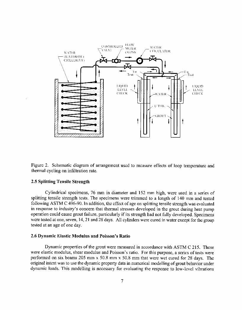
Figure 2. Schematic diagram of arrangement used to measure effects of loop temperature and thermal cycling on infiltration rate.
2.5 Splitting Tensile Strength
Cylindrical specimens, 76 mm in diameter and 152 mm high, were used in a series of splitting tensile strength tests. The specimens were trimmed to a length of 140 ‘mm and tested following ASTM C 496-90. In addition, the effect of age on splitting tensile strength was evaluated in response to industry’s concern that thermal stresses developed in the grout during heat pump operation could cause grout failure, particularly if its strength had not fully developed. Specimens were tested at one, seven, 14,21 and 28 days. All cylinders were cured in water exce:pt for the group tested at an age of one day.
2.6 Dynamic Elastic Modulus and Poisson’s Ratio
Dynamic properties of the grout were measured in accordance with ASTM C 2 15. These were elastic modulus, shear modulus and Poisson’s ratio. For this purpose, a series of tests were performed on six beams 205 mm x 50.8 mm x 50.8 mm that were wet cured for 28 days. The original intent was to use the dynamic property data in numerical modelling of grout behavior under dynamic loads. This modelling is necessary for evaluating the response to low-level vibrations
7

which are applied during proposed non-destructive evaluation of bond integrity in grouted boreholes.
2.7 Other Properties
The experimental procedures for measuring other grout properties that have been investigated throughout this project, such as thermal conductivity, coefficient of thermal expansion, linear shrinkage, bond strength, freeze-thaw durability, sulphate resistance, exotherm, leaching, ultrasonic pulse velocity, static elastic modulus and compressive and flexural strength, are documented in Allan (1997) and Allan and Philippacopoulos (1998).

3.0 EXPERIMENTAL RESULTS
In this section the results obtained in FY 99 are presented. Additionally,, a summary of important properties of Mix 111 determined previously is given.
3.1 Coefficient of Permeability
The coefficient of permeability results for the bulk grouts are presented in Table 4. The system permeabilities for grouts cast around a U-loop are given in Table 5. Figure 3 compares the results graphically.
Table 4. Coefficient of Permeability for Bulk Grouts
Mix 115 6.3 x lo-“+ 7 x lo-” --
Table 5. Coefficient of Permeability for Grout/U-loop System
Grout Mix Permeability (cm/s)
Mix 111 1.9 x lO-‘It 2.1 x 1o‘8
Mix 114 I 2.4 x lo-’ f 1 x lo-’
Mix 115 5.3 x lo-:’ IL 1.4 x lo-‘,
Neat Cement (w/c = 0.6) I 7.5 x l.o-6 + 9 x lo-’
9

%
5 le-9 ._ g 9 le-10
111 114 115 111 114 115 bulk bulk bulk U-loop U-loop U-loop
Figure 3. Coefficient of permeability for bulk grout and grout’U-loop system.
3.2 Infiltration Rate
Figure 4 is a plot of infiltration rate versus time on the ‘long tube tests conducted at room temperature for Mix 111 and neat cement grouts. Each data point represents the average for two tubes. The initial two data points were measured over a time interval of two days and subsequent points indicate the infiltration rate over a prior seven day interval. The mean values after 133 days were 2.9 x lo-’ cm/s and 6.7 x lo-’ cm/s for Mix 111 and neat cement, respectively. There was no outflow from the systems and, therefore, it was not possible to calculate falling hea.d permeability.
4.0e-6 zc g 3.5e-6
3 3.0e-6 2 z 2.5e-6 % E 2.0e-6
s ‘G 1.5e-6 2 g l.Oe-6 S
5.0e-7
,
0 10 20 30 40 50 60 70 80 90 100 110 120 130 140
Time (days)
Figure 4. Infiltration rate versus time for 5.1 m long grouted tubes at room temperature.
10

The infiltration rate results for the short tubes grouted with Mix 111 are sholwn in Figure 5. The mean values are shown and the time interval for each data point was 7 days. The periods when
the heater and chiller were on are indicated. The mean infiltration rate for the tubes grouted with Mix 111 after 68 days at room temperature was 2.4 x lo-’ cm/s.
F 1.4e-6 : E 0 l.Ze-6 -
8 2 l.Oe-6
d . l
$ 6.0e-7 -
2 s 6.0e-7 -. ._ l
S 4.0e-7 - 2 z 0 2 2.0e-7 , -
0 l
0.0 L 0 IO 20 30 40 50 60 70 60 90 100110 120130140 150
Time (days)
Figure 5. Infiltration rate versus time for Mix 111 grouted tubes subjected to thermal cycling.
Figures 6 and 7 show the equivalent test data for Mixes 114 and 115. The tests are still in progress and the complete results will be reported in the future. The mean infiltration rates after 63 days at room temperature were 1.6 x 10m7 and 2.0 x lo-’ cm/s for Mixes 114 and 115, respectively.
Attempts to measure infiltration rate on bentonite grout were unsuccessful because the material oozed out of the tube outlet under the head of water. ‘Therefore, tests on bentonite were discontinued.
11

1.4e-6
1.2e-6
1 .Oe-6 i
8.0e-7 1
6.0e-7 . 1 4.0e-7 _t
‘:o’i . : ~ . ; l =/,
0 20 40 60 80 120
Time (days)
Figure 6. Infiltration rate versus time for Mix 114 grouted tubes subjected to thermal cycling.
1.4e-6 -
1.2e-6 -
l.Oe-6 -
8.0e-7 -
6.0e-7 -
4.0e-7 -
2.0e-7 -
.
.
. . . .
. .
0.0 r I I I
0 20 40 60
.
Time (days)
80 100 120
Figure 7. Infiltration rate versus time for Mix 115 grouted tubes subjected to thermal cycling.
12

3.3 Splitting Tensile Strength
The development of splitting tensile strength with time for Mix 111 is depicted in Figure 8.
r
T
-
1
-
-
7
-
L
- -
14
Time (days)
_I_
-
21
-
_L
- 28
I Figure 8. Splitting tensile strength versus time for Mix 111.
3.4 Dynamic Elastic Modulus and Poisson’s Ratio
The dynamic properties of Mix 111 are summarized in Table 6. Static properties are included in Table 7.
Table 6. Dynamic Elastic Properties of Mix 111.
--
31.8 f 2.1
Dynamic Shear Modulus (GPa) I 12.7 f 0.7
Dynamic Poisson’s Ratio
13

3.5 Summary of Properties
Table 7 summarizes the properties of Mix 111 grout. De:tails of properties measured in prior research are given in Allan (1997) and Allan and Philippacopoulos (1998).
Table 7. Summary of Properties for Mix 111 Grout
-=
Thermal Conductivity, Saturated (W/m.K)
Thermal Conductivity, Dried (W/m.K)
Thermal Conductivity, Saturated, Field Mixed (W/m.K:) -
Specific Gravity -
Coefficient of Permeability (cm/s)
Bond Strength to HDPE @Pa)
28 Day Compressive Strength (MPa)
28 Day Splitting Tensile Strength (MPa) -
56 Day Flexural Strength (MPa) -
Static Elastic Modulus (GPa)
Static Poisson’s Ratio
Dynamic Elastic Modulus (GPa)
Dynamic Shear Modulus (GPa)
Dynamic Poisson’s Ratio
2.423 f 0.045
2.160 f 0.038
2.189 IL 0.057
2.18
1.6 x lo-”
150 k 20.5
36.7 !I 4.2
6.01 I!I 0.48
6.35 f 0.72
13.8 f 0.9
0.21 I!I 0.02
31.8 f 2.1
12.7 f 0.7
0.25 + 0.02
14

4.0 DISCUSSION OF EXPERIMENTAL RESULTS
Mix 111 in bulk form has a relatively low coefficient of permeability (hydraulic conductivity) that corresponds with what would be expected for the water/cement ratio. Addition of ground granulated blast furnace slag did not alter the coefficient of permeability as measured at 28 days. The permeability for the fly ash-modified grout was significantly higher. ‘With prolonged curing and ongoing hydration the permeability may be reduced although this was not investigated.
While coefficient of permeability of the bulk material. is *an important property, the hydraulic characteristics of the grouted borehole system are of key interest for evaluating the ability of the grout to act as an effective sealant. Since the bonding between grout and U-loop is imperfect the permeability of the grout/loop system is not equivalent to that of the bulk grout. This principle is applicable to all grout types, not just cementitious. The coefficients of permeability for grout/U- loop systems were several orders of magnitude higher than that of the bulk grouts due to the contribution of flow at the grout/pipe interfaces. Of the grouts tested, Mix 111 had the lowest system coefficient of permeability. Incorporation of fly ash in the grout increased system permeability and this is attributed to higher shrinkage and poorer bonding to the U-loop (Allan, 1997). All superplasticized cement-sand grouts had significantly better sealing performance than neat cement with w/c = 0.6.
Studies performed last year demonstrated the temperature dependence of system coefficient of permeability due to thermal mismatch (Allan and Philippacopoulos, 1998, 1999). Mix 111 was found to maintain lower system permeability between 1” and 35°C than neat cement grouts with w/c ranging from 0.4 to 0.8. Addition of latex to the grout formulation did not reduce coefficient of permeability.
Infiltration tests performed at room temperature on the 5.1 m long grouted tubes containing a U-loop demonstrated that the Mix 11 I cement-sand grout has a consistently lower infiltration rate. Infiltration decreased with time for both grouts due to ongoing cement hydration and associated changes in pore structure. Also, since the grouts were not saturated at the commencement of the tests there may have been some water absorption in the initial stages that contributes lto the measured infiltration rates.
The infiltration tests performed on 80 cm long tubes grouted with Mix 111 showed a decreasing trend in mean infiltration rate with time during the first 68 days under room temperature conditions. When hot water was circulated through the U-loop the mean infiltration rate was initially approximately the same, followed by an increase and subsequent return to the initial value. Circulation of cold water caused the mean infiltration rate to increase during the first two weeks and then decrease in the third week. During the second hot water cycle mean infiltration rate increased again. The final cold water cycle saw the mean infiltration rate remain constant. In all cases the mean infiltration rate remained of the order of lo-’ cm/s. It was expected that infiltration rate may decrease during the hot cycles due to radial expansion of the U-loop since polyethylene has a higher coefficient of thermal expansion than grout. The increase in temperature of the heald of infiltrating water may have been influential due to corresponding reduction of viscosity. Conversely, an
15

increase in infiltration rate was expected when cold water was circulated through th,e U-loop. This was observed on some occasions, but was not consistent. The results obtained suggest that sealing capability of the Mix 111 grout is not significantly impaired by elevated or decreased temperature circulating fluid and that infiltration rate remains at the same order of magnitude.
The infiltration rates for the tubes grouted with Mix 114 were more variable, especially in the first 63 days. The mean infiltration rates were a similar magnitude to Mix 111. Circulation of hot or cold water initially increased the mean infiltration rates and these decreased with progression of the experiment. The tubes grouted with Mix 115 had similar infiltration rates to Mixes 111 and 114 despite the fact that higher coefficients of permeability were measured for this material. Mean infiltration rate was not significantly influenced by circulation of hot water. An initial increase in infiltration rate was observed during the cold cycle, followed by a decrease.
In summary, for the three superplasticized cement-sand grouts tested and the experimental conditions used, low infiltration rates were maintained during thermal cycling. The variations in infiltration rate with temperature lacked consistency and are not readily explained by simple differential thermal expansion of system components. There may be other contributions to the infiltration rate such as flow between the outer PVC tube and grout. It is recommended that future work should consider measuring in-situ infiltration rate on grouted boreholes in order to include the interfacial conditions between grout and surrounding formation and to confirm the sealing ability of the cement-sand grouts under actual operating conditions. The latter would encompass more realistic temperature gradients in the coupled system.
The splitting tensile strength of Mix 111 increases with age as expected and the strength at one day is 54% of that at 28 days. The grout shows reasonable tensile strength development. The results can be compared with the thermal stresses likely to be induced in the grouts as discussed in Section 7.0. None of the grouted tubes used in infiltration tests developed tensile cracks due to expansion of the U-loop.
The dynamic elastic modulus was significantly higher than the static value. The phenomenon of higher modulus obtained by vibration rather than compressive loading is also found for concrete and attributed to lack of induced microcracking and creep (Neville, 1996). The static Poisson’s ratio for the grout was within the typical range for concrete. A higher value was obtained by the dynamic method for the same reason that the dynamic modulus was higher (Neville, 1996). The mechanical properties of grout within a borehole may change with in-situ curing conditions and
operational temperature and this needs to be taken into consideration.
16

5.0 FIELD TEST RESULTS
5.1 Oklahoma State University
Two 250 fi deep boreholes were grouted at Oklahoma State University in August 1998. The grout was the same as that given in Table 3 except that bentonite was omitted. This resulted in some pumping problems due to excessive settling of sand. These problems were later corrected during the field trials at Sandia. The results of the field tests performed to date at OSU are summarized in Figure 9. The thermal resistance of Mix 111 was compared with 15% and 30% solids bentonite grouts and 63.5% solids thermally enhanced bentonite. The res,uIts indicate that when steady state was approached the resistance for Mix 111 was 29% lower than bentonite and 16% lower than thermally enhanced bentonite for boreholes of similar diameter.
0.8
,J 0.7 m
g & 0.6 L
Cenmtitious Gat
‘+3.6in.:WfBH30 ##l
+4.5in.3@& EHXI #4 ~
-A- 3.6 in. 63.5”/9 TGt35 #2
x4.5 in. 63.5% TS65 #3 ~
e3.5ir-i. ‘150/9 GYvW ti 1
+ 4.9 in. &P/Q CG1 11#6a 1
Figure 9. Results from field tests at Oklahoma State University.
17

5.2 Sandia National Laboratories
The field tests performed at Sandia enabled evaluation of the grout performance under arid conditions. Two boreholes 250 ft deep were grouted with Mix 111 at the site in September 1998 along with one completed with 30% solids bentonite grout. One ‘of the Mix 111 boreholes was based on Type I cement and the other on Type V (sulfate resistant). Type V has a lower exotherm. The results of the field tests are presented in Figure 10. The borehole with the grout containing Type V cement had lower thermal resistance, although further tests would be necessary to reach a statistically valid conclusion. The two Mix 111 boreholes had thermal resistances 26 and 35% lower than bentonite at 70 hours. It is recommended that additional long-term data on the grout behaviour under operational loads in the dry environment be obtained.
0 20 40 60 80 100 120 140 160
dew=)
Figure IO. Field test results from Sandia National Laboratories.
The field results obtained so far verify that improved perfkrnance can be ach:ieved with Mix 111 that is properly mixed and placed. Evaluation after repeated heating and cooling loads would be valuable and provide important information for GHP loop design purposes.
18
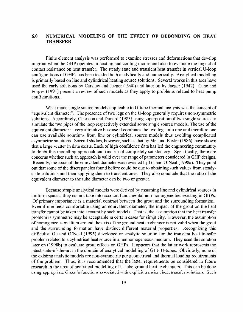
6.0 NUMERICAL MODELING OF THE EFFECT OF DEBONDING ON HEAT TRANSFER
Finite element analysis was performed to examine stresses and deformations that develop in grout when the GHP operates in heating and cooling modes and also to evaluate the impact of contact resistance on heat transfer. The steady state and transient heat transfer in vertical U-loop configurations of GHPs has been tackled both analytically and numerically. Analytical modelling is primarily based on line and cylindrical heating source solutions. Several works in this area have used the early solutions by Carslaw and Jaeger (1940) and later on by Jaeger (1942). Cane and Forges (199 1) present a review of such models as they apply to problems related to heat pump configurations.
What made single source models applicable to U-tube thermal analysis was the concept of “equivalent diameter”. The presence of two legs on the U-loop generally requires non-symmetric solutions. Accordingly, Claesson and Dunard (1983) using superposition of two single sources to simulate the two pipes of the loop respectively extended some single source models. The use of the equivalent diameter is very attractive because it combines the two legs into one and therefore one can use available solutions from line or cylindrical source models thus avoiding complicated asymmetric solutions. Several studies, however, such as that by Mei and Baxter (1986), have shown that a large scatter in data exists. Lack of high confidence data has led the engineering community to doubt this modelling approach and find it not completely satisfactory. Specifically, there are concerns whether such an approach is valid over the range of parameters considered in GHP designs. Recently, the issue of the equivalent diameter was revisited by Gu and O’Neal(1998a). They point
out that some of the discrepancies found before could be due to obtaining such values from steady- state solutions and then applying them to transient ones. They also conclude that the ratio of the equivalent diameter to the tube diameter can be two or greater.
Because simple analytical models were derived by assuming line and cylindrical sources in uniform spaces, they cannot take into account fundamental non-homogeneities existing in GHPs. Of primary importance is a material contrast between the grout and the surrounding formation.
Even if one feels comfortable using an equivalent diameter, the impact of the grout on the heat transfer cannot be taken into account by such models. That is, the assumption that the heat transfer problem is symmetric may be acceptable in certain cases for simplicity. However, the assumption of homogeneous medium around the axis of the ground heat exchanger is not valid when the grout and the surrounding formation have distinct different material properties. Recognizing this difficulty, Gu and O’Neal (1995) developed an analytic solution for the transient heat transfer problem related to a cylindrical heat source in a nonhomogeneous medium. They used this solution later on (1998b) to evaluate grout effects on GHPs. It appears that the latter work; represents the latest state-of-the-art in the domain of analytical modelling of GHP U-tubes. Obviously, none of the existing analytic models are non-symmetric per geometrical and thermal loading requirements of the problem. Thus, it is recommended that the latter requirements be considered in future research in the area of analytical modelling of U-tube ground heat exchangers. This can be done using appropriate Green’s functions associated with explicit transient heat transfer solutions. Such
19
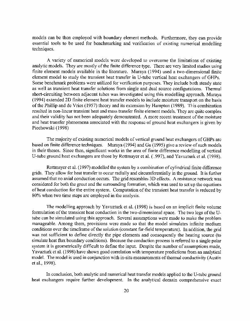
models can be then employed with boundary element methods. Furthermore, they can provide essential tools to be used for benchmarking and verification of existing numerical modelling techniques.
A variety of numerical models were developed to overcome the limitations of existing analytic models. They are mostly of the finite difference type. There are very limited studies using finite element models available in the literature. Muraya (1994) used a two-dimensional finite element model to study the transient heat transfer in U-tube vertical heat exchan,gers of GHPs. Some benchmark problems were utilized for verification purposes. They include both steady state as well as transient heat transfer solutions from single and dual source configurations. Thermal short-circuiting between adjacent tubes was investigated using this modelling approach. Muraya (1994) extended 2D finite element heat transfer models to include moisture transport on the basis of the Phillip and de Vries (1957) theory and its extension by Hampton (1989). Thds combination resulted in non-linear transient heat and mass transfer finite element models. They are quite complex and their validity has not been adequately demonstrated. A more recent treatment of the moisture and heat transfer phenomena associated with the response of ground heat exchangers is given by Piechowski (1998)
The majority of existing numerical models of vertical ground heat exchangers of GHPs are based on finite difference techniques. Muraya (1994) and Gu (1995) give a review of such models in their theses. Since then, significant works in the area of finite difference modelling of vertical U-tube ground heat exchangers are those by Rottmayer et al. (l997), and Yavuzturk et al. (1998).
Rottmayer et al. (1997) modelled the system by a combination of cylindrical finite difference grids. They allow for heat transfer to occur radially and circumferentially in the ground. It is further assumed that no axial conduction occurs. The grid resembles 3D effects. A resistance network was considered for both the grout and the surrounding formation, which was used to set up the equations of heat conduction for the entire system. Computation of the transient heat transfer is reduced by 80% when two time steps are employed in the analysis.
The modelling approach by Yavuzturk et al. (1998) is based on an implicit finite volume formulation of the transient heat conduction in the two-dimensional space. The two legs of the U- tube can be simulated using this approach. Several assumptions were made to ma:ke the problem manageable. Among them, provisions were made so that the model simulates infinite medium conditions over the timeframe of the solution (constant far-field temperature). In adldition, the grid was not sufficient to define directly the pipe elements and consequently the heating source (to simulate heat flux boundary conditions). Because the conduction process is referred to a single polar system it is geometrically difficult to define the input. Despite the number of assumptions made, Yavuzturk et al. (1998) have shown good correlation with temperature predictions from an analytical model. The model is used in conjunction with in-situ measurements of thermal conductivity (Austin et al., 1998).
In conclusion, both analytic and numerical heat transfer models applied to the U-tube ground heat exchangers require further development. In the analytical domain comprehensive exact
20
solutions to the asymmetric 2D problem (including pipes, grout and formation) should be pursued so that available modelling techniques can be validated. In the numerical domain, the focus should be the finite element analysis, thus taking advantage of the significant developments in the last decade in this area.
Current finite difference numerical solutions of the two-dimensional heat conduction equation for application to vertical ground heat exchangers assume perfect bonding between the system components. Shrinkage of grout/backfill and soil, porosity and inhomogeneities in the surrounding formation, or entrained air in the grout due to improper borehole grouting techniques are possible scenarios that will cause interfacial contact resistance and modify the heat transfer process. Shrinkage is a particular concern during heat rejection Ior where the ground heat exchanger is installed above the water table. Differential thermal contraction of the high density polyethylene U-loop and grout when the heat pump operates in heating mode will also potentially cause interfacial gaps.
Bentonite grouts are susceptible to high shrinkage under drying conditions. Studies of the interfacial microstructure between neat cement grouts and U-loop pipes have revealed gaps up to 0.32 mm wide (Allan, 1998; Allan and Philippacopoulos, 1998). Gaps for cement-sand grouts tend to be smaller and discontinuous both radially and axially. Thus, although interfacial bonding remains imperfect, better heat transfer can be expected for suitably designed cement-sand grouts in addition to lower infiltration rates in grouted boreholes. Th.e presence and observed discontinuity of interfacial gaps requires that heat transfer be analyzed using models that can take this into account.
In this study we concentrate on potential quantitative effects due to the presence of gaps (debonding) at various interfaces of the system. A variety of gaps developed at the (a) pipe/grout and (b) grout/soil interfaces are considered. The solutions discussed above have inherent restrictions and therefore are not appropriate for analyzing such effects. Specifically, they a:re dealing with linear continuous solutions of the heat conduction equation. Consequently, we tackle this problem in two different ways. First a set of simplified models are obtained that incorporate the basic ingredients of the problem. Such models are developed from fundamental one-dimensional conduction formulas that are applied to a composite cylindrical system. In addition., finite element analysis is performed assuming a variety of spatially distributed air gaps formed in the system. Using both simplified and finite element models, a paramet.ric variation is perfomted considering different materials and gap sizes. All models are based on steady-state heat transfer. Accordingly, an upper bound approach is considered in evaluating such effects.
6.1 One-Dimensional Models
Simple models that allow the effects of potential interfacial gaps on the heat transfer in ground heat exchangers to be quantified were derived using basic formulas for uniform radial heat conduction. Concentric cylinder models have been used in previous studies of total thermal resistance (e.g., Kavanaugh, 1984; Braud, 1991). A three-component medium was considered to model the borehole associated with the ground heat exchanger and the surrounding formation.
21
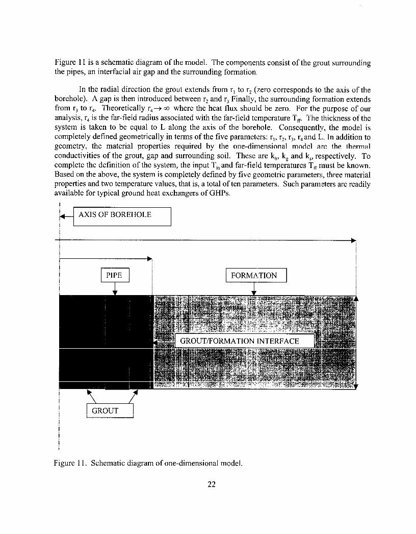
Figure 11 is a schematic diagram of the model. The components consist of the grout surrounding the pipes, an interfacial air gap and the surrounding formation.
In the radial direction the grout extends from rl to r, (zero corresponds to the axis of the borehole). A gap is then introduced between r2 and r3 Finally, the surrounding formation extends from r3 to r,. Theoretically r,-+ 00 where the heat flux should be zero. For the purpose of our analysis, r, is the far-field radius associated with the far-field temperature T, The ,thickness of the system is taken to be equal to L along the axis of the borelhole. Consequently, the model is completely defined geometrically in terms of the five parameters: r,, r2, r,, r, and L. In addition to geometry, the material properties required by the one-dimensional model are the thermal conductivities of the grout, gap and surrounding soil. These are k,, k, and k,, respectively. To complete the definition of the system, the input T, and far-field temperatures T, rnust be known. Based on the above, the system is completely defined by five geometric parameters, three material properties and two temperature values, that is, a total of ten parameters. Such paramleters are readily available for typical ground heat exchangers of GHPs.
I I + AXIS OF BOREHOLE
I
-- ,:
h
I PIPE j
Figure 11. Schematic diagram of one-dimensional model.
22

Steady-state heat conduction is assumed. The heat rate associated with this model is then constant while the heat flux varies inversely proportional to the radial distance r (l/r variation). The first step is to compute the interface temperatures T, = T(rJ and T, = T(rJ. Let &,i;i = b, g, s denote
the thermal resistances of the grout, gap and soil respectively. Furthermore, let 9r,i and q,,i denote
the heat transfer rate and heat flux respectively. By enforcing continuity of heat flow at both interfaces r = r, and r = r, respectively, then the temperatures in question can be obtained from the solution of a 2x2 problem as follows
(1)
where aand p are dimensionless quantities expressing thermal resistance ratios clefined as
R a=r.6
Rt,g (2a)
1 Rtz _=- P Rt,s
W9
The thermal resistances can be obtained from standard formulas (see e.g., Incropera, 1990) as follows
(3c)
23
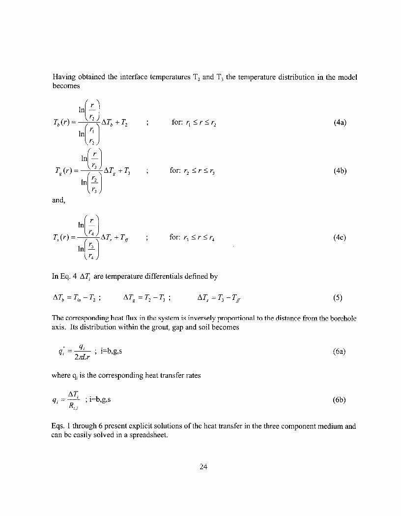
Having obtained the interface temperatures T, and T, the temperature distribution in the model becomes
and,
T,(r) =
9 for: r, I r I r2
9 for: r2 I r I r3
7 for: r3 I r I r4
(44
W)
(44
In Eq. 4 AT are temperature differentials defined by
ATb =T.n -T2 ; ATg =T2-q ; AT, =T3 -TJr (9
The corresponding heat flux in the system is inversely proportional to the distance from the borehole axis. Its distribution within the grout, gap and soil becomes
,, 4i - * 4izzdr ) i=b,g,s
where qi is the corresponding heat transfer rates
(64
AT. qi =----L
R,,i ; i=b,g,s (6b)
Eqs. 1 through 6 present explicit solutions of the heat transfer in the three component medium and can be easily solved in a spreadsheet.
24

In the above derivations it has been assumed that one knows the input and far-field temperatures Ti, and T, respectively. In certain applications, however, instead of the input temperature Tin, the input heat flow is known. This, for example, is the case for fiield tests, which are performed to measure in-situ thermal properties (see e.g., Austin et al., 1998). Such cases require a different set of boundary conditions for the three medium system. Specifically:
411 = ci’Cr)I,=, ; q, = 2dr,q~ 0
(7)
are the input heat flux and heat transfer rates respectively. Enforcing continuity of heat rate at all interfaces yields a 3x3 system. The latter can be solved for the input Ti” and interface temperatures, T, and T,. Solution of the resulting 3x3 system yields
where Et,i ; i=b,g,s are the thermal resistances of the components of the system given by Eq. 3 and q, is the prescribed heat rate at the inner surface. Having obtained the input and interface temperatures from Eq. 8, backsubstitution into Eqs. 4, 5 and 6 results in the required temperature and heat flux distributions in the system.
6.2 Numerical Evaluation of Debonding
The effect of debonding in ground heat exchangers of GHPs was investigated using (a) the simple radial one-dimensional models presented in the previous section and (b) finite element two- dimensional models. Both these types of models were sufficiently adequate in capturing the fundamental effects in the heat conduction process due to formation of gaps in the system. One- dimensional models do not account for spatial variability in the circumferential direction that was observed in interfacial microstructure studies. Hence, effects due to the latter were evaluated by finite element two-dimensional heat conduction. Primarily, two cases of debonding vvere considered in this study: (a) debonding at the grout/formation interface and (b) debonding at the pipe/grout interface.
A typical 4-inch diameter borehole was considered grouted with Mix 111. Other materials such as bentonite were also used in our parametric studies. The temperature for the heating mode was taken as 38°F. This represents an average of the entering (4l”F) and leaving water temperatures (35°F) in the piping loop for this mode of operation. Similarly, the cooling mode temperature was taken as 9 1.4”F which also represents the average of the enteri:ng and leaving water temperatures 86°F and 96.8”F respectively. Note that temperature averages were used only in conjunction with the one-dimensional models.
25

In the two-dimensional finite element analysis the entering and leaving temperatures can be directly applied at the two pipes which are incorporated into the models. The far-fi’eld temperature was set to 55.4”F. After a few parametric computer runs, it was decided to keep the far-field radius at 10 ft. Practically, further increases in the far-field radius did not affect the results. Finally, the following values for the thermal conductivities were used: (a) Mix 111: 2.42 W/m.K (0.116 Btu/hr- in-OF); (b) Bentonite: 0.75 W/m.K (0.0361 Btu/hr-in-OF); (c) Formation 1.72 W/m.K (0.083 Btu/hr- in-OF). The corresponding value for the air-filled gaps was 0.02617 W/m.K (1.29 x 10” Btu/hr-in-OF). It is recognized that under some circumstances interfacial gaps may be filled with water.
6.2.1 One-Dimensional Analysis
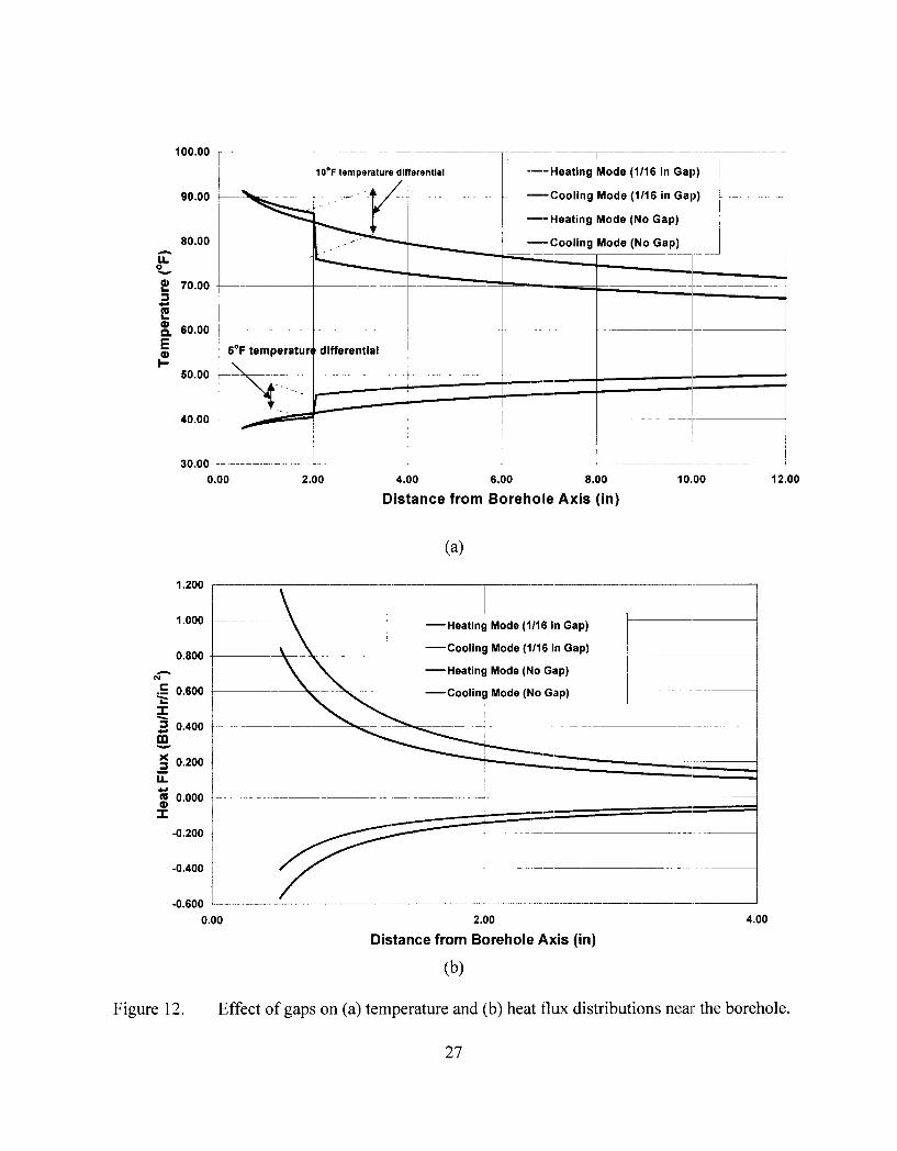
Figure 12 demonstrates the effects of debonding on the temperature and heat flux distributions near the borehole of the ground heat exchanger. The grout material is Mix 111. A l/16” air gap has been introduced at the grout/formation interface. From Figure 12(a) it can be seen that when the distance from the borehole becomes equal to 2 inches a temperature drop takes place for both modes of operation of the heat pump. This drop is about 5°F for the heating and 1O”F for the cooling modes respectively. In addition, the presence of the gap also reduces the heat flow. This can be seen from Figure 12(b) where the flux is reduced especially near the borehole. This behavior occurs for both modes of operation. Note that for the heating mode the flux is negative signifying the fact that during this mode heat is flowing from the surrounding formation into the borehole. Furthermore, from Figure 12(a) it can be seen that as the distance from the axis of the borehole increases, the temperature for both modes of operation converges to the far-field temperature. A second point of interest is related to the variation of the heat flow with the distance from the axis of the borehole. Specifically, from Figure 12(b) it can be seen that as the distance from the axis of the system increases the flux converges to zero. These two observations correlate accurately with the one-dimensional modeling formulation presented in the previous section.
Comparisons between different grout materials are shown in Figure 13. Temperature and heat variations in the vicinity of the ground heat exchanger were obtained for grout materials such as Mix 111 and bentonite. The results shown in Figure 13 correspond to the cooling mode of operation. Note from this figure that Mix 111 handles heat conduction in the ground heat exchanger significantly better than bentonite. Since bentonite has a high potential for shrinkage and consequently debonding is likely to occur with the surrounding formation the latter case is also included in Figure 13 for comparison (i.e., results for l/16” gap). The observed reduction in temperature for the no gap case between the two materials is due to the fact that Mix 111 has been designed with significantly higher thermal conductivity than that of the bentonite. Additionally, the presence of the gap produces a further reduction associated with a temperature drop at the grout/formation interface. Finally, the behavior of the heat flux for these cases i,s also similar. Specifically, the heat flux is much less for bentonite grout with or without a gap. Tlhis reduction is more pronounced closer to the borehole.
26
100.00
90.00
80.00
OF 2 70.00 3
t;i
t p 60.00
E
c
--Cooling Mode (No Gap)
1 6’F temperature differential ~
4.00 6.00 8.00
Distance from Borehole Axis (in)
1.200
1 .ooo
0.800
N-
= c 0.600
z 2 0.400
%
5 0.200
E
t;i
i
0.000
--Heating Mode (1116 in Gap)
-Cooling Mode (l/16 in Gap)
-Heating Mode (No Gap)
-Cooling Mode (No G.ap)
-0.200
-0.400
-0.600 _____..__.-__- -.--
0.00 2.00
Distance from Borehole Axis (in)
Fi gure 12. Effect of gaps on (a) temperature and (b) heat flux distributions near the borehole.
27

95.00
90.00
85.00
ci 0_80.00
!I 3 ; 75.00
t
;70.00
l-
85.00
80.00
--- Bentonite (?/I6 in Gap)
0.00 9.00 18.00 27.00 38.00
1.20
1.00
20.80 e I ‘3
go.50
5 ii
t;i @ 0.40 I
0.20
0.00
Distance from Borehole Axis (in)
z\,z:I::;lI::y- -._::
.-- Bentonite (l/16 in Gap) ,~ . ~_~
2.00
Distance from Borehole Axis (in)
(4 Figure 13. Comparison between different grout materials: (a) temperature and (b) heat flux distributions.
28

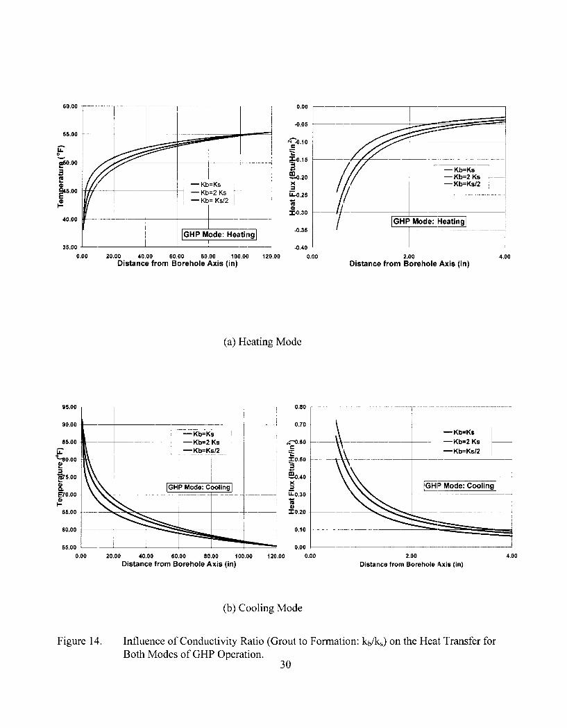
Parametric variations were performed considering different materials for the grout and the formation respectively. These results are shown in Figure 14 for the heating and cooling modes of operation. Both temperature and heat flux variations were evaluated. The thermal conductivity of the grout was taken as equal, then half and finally twice that of the formation. From our results we concluded that the temperature and heat flux distributions in the system depend only on the conductivity ratio between the two materials (grout-to-formatioa) and not on their absolute values. This is consistent with uniform radial heat flow theory. The plots in Figure 14 indicate that higher
grout-to-formation ratio yields higher heat flux. From the sa.me figure it is also) noted that the temperature varies differently in the cooling and heating modes. Therefore, acceptance design criteria should be based on the fact that better heat transfer rates are obtained for higher grout-to- formation thermal conductivity ratios. For example, in the cooling mode of operation the heat transfer rate increased from 11.5 to 13.2 Btu/hr when the grout-to-formation conductivity ratio increases to 2. This, in turn, reflects a reduction in the total resistance of the system. Specifically, the total resistance was decreased from 1.5 to 1.3 F-hr/Btu. Similarly, when the grout-to-formation conductivity ratio was reduced to 0.5, the overall heat transfer rate was reduced from 11.5 to 9.2 Btu/hr.
6.2.2 Finite Element Analysis
A two-dimensional finite element analysis of the heat conduction in the ground heat exchanger was performed in order to account for asymmetric heat response resulting from the spatial distribution of the gaps. Such analysis enables us to obtain a better understanding of the spatial distribution of the effects due to the existence of gaps in the sy,stem. The finite element modeling of the ground-coupled heat pump system was performed using the ANSYS code. The finite element model incorporated both pipes, the grout and the surrounding formation. It consisted of 608 nodal points and 588 elements. Specifically, element PLANE55 (thermal solid) was employed which can be applied in either plane or axisymmetric two-dimensional thermal conduction problems. PLANE55 has four nodes having a single degree-of-freedolm (temperature) at each node. A triangular option also exists. A finer mesh was used inside the ground heat exchanger. The fineness of the grid representing the surrounding formation was reduced with the distance frolm the borehole axis. Figure 15 shows the finite element model near the boreh.ole.
The boundary conditions considered were: (a) prescribed constant heat flux at the inside surface of pipes and, (b) prescribed constant far-field temperature. When symmetric distributions of gaps are considered, then only half of the model is required. In this case, the axis that is defined by the centers of the two pipes becomes an axis of symmetry in the solution. Along this axis, a zero heat flux condition is required. However, for general scenarios of gap spatial distribution, no symmetry in the heat conduction solution exists and therefore the whole finite element model must be considered in the analysis.
29
55.00
G 0
20.00
3 E
$5.00 E I-”
40.00
35.00
0.00 20.00 40.00 50.00 80.00 100.00 Distance from Borehole Axis (in)
2.00 IDistance from Borehole Axis (in)
4.00
(a) Heating Mode
0.00 20.00 40.00 50.00 80.00 100.00 120.00 0.00 2.00 4.00
Distance from Borehole Axis (in) Distance from Borehole Axis (in)
(b) Cooling Mode
Figure 14. Influence of Conductivity Ratio (Grout to Formation: kb/k,) on the Heat Transfer for Both Modes of GHP Operation.
30

Figure 15. Finite element model near borehole.
Several heat transfer finite element analyses were performed. The thermal resistance and overall heat transfer coeffkient of the ground heat exchanger were evaluated by applying a heat flux of 1 .O Btu/hr/A2 at the inner surface of both pipes. Subsequently, the temperature field was evaluated for different gap scenarios. In each case, the temperature of each pipe was computed as the average of all interior nodes associated with the pipe. The average between the two pipes was then treated as the input temperature for the system. Similarly, the output temperature for calculating the heat transfer coefficient was obtained as the average of all nodes alt a circle just outside the borehole (having radius equal to the radius of the borehole plus the gap width). Finally, the total resistance was then obtained by dividing the difference between the input and output temperature by the total input heat rate. Since two-dimensional analyses were performed, all computations were conducted considering a unit length of the borehole/formation system. The grouting material used was bentonite.
As indicated previously, two types of debonding were investigated in the pr’esent study, i.e., debonding between: (a) grout and formation and (b) grout and pipes. Figures 16 and 17 demonstrate results obtained on the temperature distribution for the former case. For clarity, Figures 16 and 17 display results only in the vicinity of the borehole (i.e., up to about one foot dktance from the borehole axis). Note that the overall finite element model extends radially up to loft from the borehole axis. Figure 16a shows the temperature distribution near the borehole for ,the no gap case. As expected, in the absence of gaps the temperature distribution is smooth and symmetric. A l/l 6-
inch gap was then introduced at the grout/formation interface. Its spatial distribution corresponds to a 90’ sector at the right side of the model. Figure 16b shows the corresponding temperature distribution. Note that, consistent with the physics of the problem, the gap inhibits the heat to flow towards the right side of the model. In these figures we display the total response field for completeness. The symmetry in the solution is readily identified.
31

Figure 16.
(W
Effect of Gap at Grout/Formation Interface. Temperatur Borehole: (a) No Gap Case (b) 90” Gap.
32
TemperatureRange (OF)
Temperature Range (OF)
m 55.4 - 55.999 m 56.599 m 57.198 m 57.738 m 58.397 a 58.996 1 59.596 w 60.195
60.794
*e Distribution Near

In order to investigate this behavior, the extent of the gap was subsequently increased to 180”. Figure 17a shows the corresponding temperature contours. As expected, the heat flow is now further restricted towards the right of the borehole. Furthermore, in response to the heat flow restriction, the temperature increases in the vicinity of the right pipe. In fact from Figure 17a it can be seen that flow is directed towards the left pipe thus increasing the temperature around it (pipe-to- pipe thermal interaction). Finally, Figure 17b displays the temperature field when complete debonding is assumed at the grout/formation interface. In the latter case, most of ,the heat flow is restricted within the borehole. From Figure 17b it can also be observed that the temperature increases near the center of the grout, between the two pipes. However, it is also significantly attenuated towards the formation due to the debonding across the entire grout/formation interface.
The results from Figures 16 and 17 indicate that the general behavior of debonding is to inhibit the heat flow. Gaps can be thought as heat flow stoppers. Since heat is prevented from radiating, localized increases in temperatures are observed. The latter can be interpreted as caused by reflection of the heat waves at the interfaces associated with gaps. The more such reflection is focussed the higher the local temperature is increased.
In order to quantify further these results, the overall thermal resistance and the heat transfer coefficient were evaluated for different debonding cases. This was done using the temperature response field from the finite element heat transfer analysis and the approach described above. The base case (no gap) associated with Figure 16a, yields a thermal resistance of 2.0 “F-hr/Btu and corresponding heat transfer coefficient equal to 0.04 Btu/hr-ft2-“F. The presence of a 90” gap (see Figure 16b) caused a 20% reduction in the overall heat transfer coefficient. Similarly, the 180” (see Figure 17a) and complete debonding (see Figure 17b) cases resulted in 33% and 60% reductions in the overall heat transfer coefficient, respectively. Finally, since the temperature field depends on the fineness of the grid, a finer model was used to obtain the results for the 90”-gap case. The difference between the two results was insignificant. For example, the average temperature of the right pipe changed by 0.1 “F. Similarly, the corresponding temperature for the left pipe changed 0.04 “F.
Results associated with potential debonding of the pipes within the borehole are given in Figures 18 and 19, which demonstrate the temperature field within the borehole. Figure 18a displays the corresponding temperature field when both pipes are considered to be completely bonded to the grout. In Figure 18b a small gap (60”sector) has been introduced at the right pipe. This caused the temperature to rise locally near the debonding area. A similar situation occurs whLen a 60” gap is introduced at both pipes interior to the borehole. Temperature attenuation is evident from Figure 19a. Such attenuation becomes more predominant when the right pipe is assumed to1 break off from the grout. The latter situation is shown in Figure 19b, in which the resulting restriction in heat flow causes the temperature to rise locally. The sharp attenuation of heat shown in Figure 19b reflects a corresponding reduction of the heat transfer coefficient. Speck fically, the heat transfer coefficient was reduced by 66%. Note that this reduction is higher than that of a 360” debonding at the grout/formation interface (see Figure 17b). In turn, this indicates that bonding between the pipes and grout is more important in terms of heat transfer than bonding between the: grout and the formation.
33

Temperature Range (OF)
55.4 56.035 56.671 57,306 57.941 58.577 59.212 59.847 60.483 61.118
Temperature Range (“F)
55 . 4 56.159 5rJ.918 El?. 677 58.436 59.135 59.954 60.713 61.472 6 2 . 2 :3 1
Figure 17. Effect of Gap at Grout/Formation Interface. Temperature Distribution Nlear
Borehole: (a) 180’ Gap (b) 360’ Gap.
34

Temperature Range (OF)
59.323 59.47'1 59.619 59 l 76.6 59.914 60 . 061 60.209 60.357 60.504 60.652
(a)
Temper Bature Ralnge (OF)
59.337 59.7 60 . 063 60.426 60.789 61.152 61.515 61.878 62.241 62.604
Figure 18. Effect of Gap at Grout/Pipe Interface. Temperature Distribution Inside the
Borehole: (a) No Gap Case (b) 60” Gap (Right Pipe-Exterior). 35

Fig1
(b)
Temperature Range (OF)
5 9 . .3 0 I 59.789 60.277 60,765 41.2Ei3 61.741 62.23 62.713 63.206 63.694
Temperature Range (OF)
59.328 59.913 60.497 61.0151 61.666 62.25 62.835 63.419 64.003 64.588
x-e 19. Effect of Gap at Grout/Pipe Interface. Temperature Distribution inside the Borehole: (a) 60’ Gap (Both Pipes-Interior) (b) 360’ Gap (Rig,ht Pipe).
36

7.0 NUMERICAL MODELING OF THERMAL STRESSES AND DEFORMATIONS
While much of the research in U-loop ground heat exchangers has focused1 on the thermal conductivity of the grout and on predictions of the temperature response, the corresponding thermal deformation and stress fields have not been addressed. Their s,ignificance is reflec:ted by the need of the designer to know the strength of the grout and its likelilhood to develop thermal fractures. Finite element analysis was performed to evaluate a) the heat transfer and b) the deformation and stress fields in the complete pipe/grout/formation system associated with U-loop ground heat exchangers.
The thermal conductivities of the pipes, grout and formation were: 0.40:, 2.42 and 1.73 W/m.K respectively. The entering and leaving water temperatures for the heating mode were: EWT=S’C, LWT=2”C for the heating mode. The corresponding values for the cooling mode were: EWT=3O”C, LWT=36”C. These values were taken as worst case averages considering their variation with depth. Additional boundary conditions were imposed for the thermal stress analysis models so that they are adequately constrained. Thermoelastic properties considered for each of the materials are: a) pipe: E=l.4 GPa, v=O.45, cx=2.16~10‘~ m/m-C; b) grout: E=13.8 GPa, v=O.2 1,
a=1.65~10-~ m/m-“C; and c) formation: E=2.0 to 5.5 GPa, v=O.33, a=1.65~10~~ m/m-“C (E=elastic modulus, v=Poisson’s ratio and a=coefficient of thermal expansion). The results were obtained with the ANSYS code.
The steady state temperature distribution is shown in Figure 20. Since the response inside the borehole is of primary interest, only results within the borehole are displayed. Similarly, thermal stresses for the cooling and heating mode of operations are shown in Figures 2 1 and .22 respectively. As expected, all results are symmetric with respect to the axis containing the two centers of the
pipes. From Figure 20 it can be seen that the temperature distribution within the borehole for both heating and cooling modes of operation is reasonably smooth. A finer discretization was employed to model the grout. Additionally, two layers of elements were used to model the polyethylene pipes. It is because of such modelling provisions that such smoothness in temperature results was
obtained. A finer mesh does not seem to be required for the temperature solutions. However, for thermal stress solutions some additional refinement may be required for areas exhibiting stress concentrations. Specifically, for both modes of operation higher thermal stresses develop in the grout around the pipes. Comparison of Figures 2 1 and 22 with Figure 20 leads to the conclusion that the stress fields is consistent with those of the temperature. Stresses are especially higher in the grout near the axis of symmetry in the exterior area. This result is consistent with the physics of the problem. It is recommended that the values of the thermal stresses in these particular areas be evaluated using finer grids consistent with standard practice w:ith similar problems
37

3eral :ure R ange (“F)
(a) Heating mode
Temperatu Ire Range C’F)
(b) Cooling mode
Figure 20. Temperature distribution.
35 35.827 36.654 37.482 38.309 39.136 39.963 40.79 41.618 42 445
82.591 84 17 85.749 97.328 86.906 90.48s 92.064 93 643 95.221 96 8
38

Stress Range (MPa)
rel -3.56 -2.12 :; -1.05 -1.89
:; ;p,‘: r-1 1.47
g :::: 3.98
(a) Principal stress Sl
Strless Range (MPa)
i: ::::; I= -6.77
: :g
;y :;:g
[-J -4.38 I_ -3.90
-3.42
(b) Principal stress S2
Figure 2 1. Thermal stresses for cooling mode of operation.
39
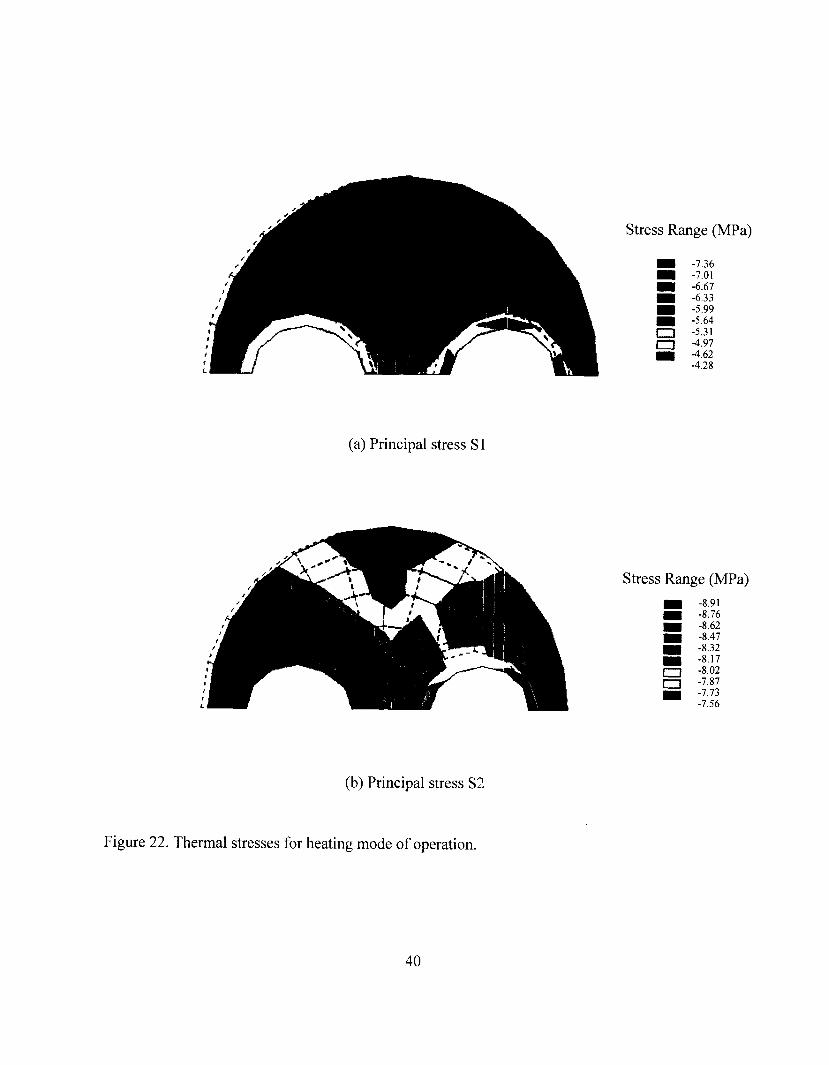
Stress Range (MPa)
: -6.67 -6.33
- :::;,"
c3 -5.31
g Ig:
-4.28
(a) Principal stress Sl
Stress Range (MPa)
I -8.76 -8.91
I -8.62 -8.47
I -8.32 -8.17 -8.02 -7.87 -1.13 -7.56
(b) Principal stress S2
Figure 22. Thermal stresses for heating mode of operation.
40
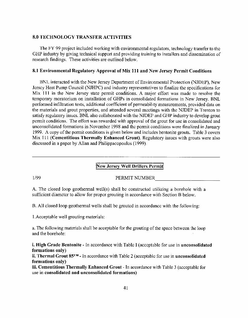
8.0 TECHNOLOGY TRANSFER ACTIVITIES
The FY 99 project included working with environmental regulators, technology transfer to the GHP industry by giving technical support and providing training to installers and dissemination of research findings. These activities are outlined below.
8.1 Environmental Regulatory Approval of Mix 111 and Nmew Jersey Permit Conditions
BNL interacted with the New Jersey Department of Environmental Protection (NJDEP), New Jersey Heat Pump Council (NJHPC) and industry representatives to finalize the specifications for Mix 111 in the New Jersey state permit conditions. A major effort was made to resolve the temporary moratorium on installation of GHPs in consolidate:d formations in New Jersey. BNL performed infiltration tests, additional coefficient of permeability measurements, provided data on the materials and grout properties, and attended several meetings with the NJDEP in Trenton to satisfy regulatory issues. BNL also collaborated with the NJDEP and GHP industry to develop grout permit conditions. The effort was rewarded with approval of the grout for use in consolidated and unconsolidated formations in November 1998 and the permit conditions were finalized in January 1999. A copy of the permit conditions is given below and includes bentonite grouts. Table 3 covers Mix 111 (Cementitious Thermally Enhanced Grout). Regulatory issues with grouts were also discussed in a paper by Allan and Philippacopoulos (1999).
Jersey Well Drillers PermitA -
l/99 PERMIT NUMBER
A. The closed loop geothermal well(s) shall be constructed utilizing a borehole: with a sufficient diameter to allow for proper grouting in accordance with Section B below.
B. All closed loop geothermal wells shall be grouted in accordance with the following:
1 .Acceptable well grouting materials:
a. The following materials shall be acceptable for the grouting of the space between lthe loop and the borehole:
i. High Grade Bentonite - In accordance with Table I (acceptable for use in unconsolidated formations only) ii. Thermal Grout 85TM - In accordance with Table 2 (acceptable for use in unconsolidated formations only) iii. Cementitious Thermally Enhanced Grout - In accordance with Table 3 (acceptable for use in consolidated and unconsolidated formations)
41

TABLE I - HIGH GRADE BENTONITE NUMBERS BASED ON 15 to 30% SOLIDS BY WEIGHT
~~~~’
*Accurate measurement of materials prior to mixing is imperative as air entrainment during the physical mixing of the slurry tends to decrease the density of the mixture.
TABLE 2 - THERMAL GROUT 85(TM) NUMBER BASED ON 63.5% SOLIDS IBY WEIGHT
Pounds of Bentonite
- Pounds of Thermal Target Gallons of Acceptable Range Target Density
Enhancement Water of Water (gallons)
I
lbs/gal* Compound* *
54 200 17.5 17-18 13.1
*Accurate measurements of materials prior to mixing is imperative as air entrainment during the physical mixing of the slurry tends to decrease the density of the mixture. **Compound shall be washed, dried silica sand which is graded and shall have less than 20% by weight retained on a U.S. Sieve #50 and shall have AFS GFN (American Foundrymen’s Society Grain Fineness Number) between 55.0 and 75.0. The silica content (SiO,) shall be greater than 99%.
TABLE 3 - CEMENTITIOUS THERMALLY ENHANCED GROUT
Pounds of Amount of Cement Superplasticizer Sand Conforming to
(Type I, II or V) (Sulfonated Naphthalene
)
94 2 1 ounces per bag of cement (not to exceed 29 ounces)
42

50(297) 30-55
lOO(149) 10-30
200(75) O-10
b. Bentonite or Thermal Grout 85(TM) shall not be used for grouting in those instances where it will come in contact with ground water having a pH less than 5.0 and/or a Total Dissolved Solids content in excess of 1,000 ppm.
c. Where the grouting material extends through zones of salt water, a salt/water resistant grout material shall be used.
2. Grout Mixing and Placement
a. High Grade Bentonite
i. Mixing - Bentonite products and additives should be mixed in accordance with manufacturers’ specifications.
ii. Pressure Grouting - The grout shall be pumped, through a tremie/grout pipe, in one continuous operation, from the bottom to the top of the space to be tilled. The tremie/grout pipe shall be installed with the closed loop upon completion of the borehole. The tremie/grout pipe may be slowly raised as the grout is being placed but the discharge end of the pipe shall remain submerged in the grout at all times until grouting is complete.
b. Thermal Grout ETM
i. Mixing - All products and materials shall be mixed in accordance with manufacturers’ specifications.
ii. Pressure Grouting - The grout shall be pumped with a positive displacement pump (piston pump strongly recommended), through a 1” or l-1/4” inside diameter tremiejgrout pipe <at a rate of 5 to 15 gallons per minute, in one continuous operation, from the bottom to the top of the space to be filled. The tremie/grout pipe shall be installed with the closed loop upon completion Iof the borehole. The tremie/grout pipe may be slowly raised as the grout is being placed but the discharge end of the pipe shall remain submerged in the grout at all times until grouting is complete.
43

c. Cementitious Thermally Enhanced Grout
i Mixing - The mix proportions given and the following “suggested mixing procedure” are for use when the grout is mixed in a low shear (paddle) mixer designed for cement-sand gr’outs. Mixing of the grout by hand, pumps or concrete ready mix trucks is not acceptable.
(a) Pre-mix bentonite with the required measured quantity of water until uniformly dispersed. (b) Place required measured quantity of superplasticizer in mixer containing the premixed bentonite and water. (c) Start mixer at low speed. (d)Mix dispersed bentonite, superplasticizer and water mixture for approximately 10 seconds (care should be taken to avoid air entrainment by mixing at excessively high speed). (e) Gradually add required quantity of cement in mixer and increase mixer speed. Mix for approximately 1 to 2 minutes or until cement is dispersed. (f) Gradually add required quantity of silica sand in mixer and increase mixer speed if necessary. (g) Mix grout until uniform (maximum of 5 minutes should be adequate).
ii. Pressure Grouting - The grout shall be pumped (piston pump is recommended), through a l-1/4” inside diameter tremie/grout pipe with an open end and sevleral side discharge outlets, in one continuous operation, from the bottom to top of the space to be filled. The tremie/grout pipe shall be installed with the closed loop upon completion of the borehole. The tremie/grout pipe may be slowly raised as the grout is being placed but the discharge end of the pipe shall remain submerged in the grout at all times until grouting is complete.
3. Potable water shall be used for mixing grouting materials and drilling fluids.
C. The circulating fluids utilized in the closed loop system shall only be potable water or an appropriate mixture of potable water with one of the following antifreeze solutions:
1. Calcium Chloride 3. Potassium Acetate 5. Propylene Glycol 2. Ethanol 4. Potassium Carbonate 6. Sodium Chloride
D. The only acceptable pipe material for the underground buried portion of the ground heat exchanger is 160 psi polyethylene pipe as specified below:
1. Polyethylene -All material shall maintain a 1600 psi hydrostatic design basis at 73.4 degrees F per ASTM D-2837, and shall be listed in PPI TR4 as a PE340’8 piping formulation. The material shall be a high density, polyethylene extrusion compound having a cell classification of PE345434C or PE355434C with a UV stabilizer of C. D or E as specified in ASTM D-3350 with the following exception: this material shall exhibit zero failures (FO) when tested for 192 or more hours under ASTM D-1693, condition C. as required in ASTM D-3350.
E. The only acceptable methods for joining buried pipe systems are by 1) the heat fusion process in accordance with the pipe manufacturer’s specifications. or 2) those joined using the IGSHPA approved mechanical stab fittings. The resultant assembly shall be leak-proof.
44

F. Prior written approval is required for any deviation to the materials or methods prescribed in the preceding conditions.
8.2 Grout Training Session, Field Demonstration and Presentations
A grout training session and field demonstration was conducted in Dover, New Jersey in collaboration with GPU Energy, NJHPC, Geothermal Resources Group and Geothermal Services in February 1999. A presentation was made to over 40 participants from New Jersey, New York and Pennsylvania on the grout properties and benefits, mix specifications and recommenlded equipment. Participants were supplied with specifications, material suppliers and permit conditions. The field
demonstration was performed by Geothermal Services and involved grouting a 400 ft borehole at the future site of the Rockaway Hilton Hotel. An in-situ thermal conductivity test was performed and showed excellent results. Figures 23 to 26 are photos from the field demonstration.
Figure 23. Field training and demonstration site at Dover, NJ.
45

Figure 24. Grout mixing equipment used by Geothermal Services at Dover field demonstration.
Figure 25. Measuring superplasticizer quantity at Dover field demonstration.
46

Figure 26. Measuring grout specific gravity at Dover field demonstration.
Various other presentations on grouting materials and re,search accomplishments were made throughout FY 99. These included:
Presentation on grouting materials at a ground source heat Ipump design seminar conducted by Professor Steve Kavanaugh (University of Alabama) in Sayreville, NJ.
1998 Geothermal Resources Council Meeting in San Diego, CA 1999 IGSHPA Conference in Stillwater, OK
1999 DOE Geothermal Program Review XVII in Berkeley, CA
DOE Geothermal Heat Pump Review Meeting in Washington, DC.
1999 Geothermal Resources Council Meeting Reno, CA (oral and poster)
8.3 Interaction with GHP Industry, Web Site and Dissemination of Information
In addition to the grout training session and presentations, other interactions with the GHP industry included supply of detailed materials, mixing and pumping specifications and quality control tests to numerous end users throughout the US, Canada, Australia, Switzerland and Japan. Technical assistance has been given to users with regard to procurement of materials, mixing and
pumping procedures and equipment recommendations. In particular, BNL assisted Enlink Geoenergy Services, Eagle Research and Ted Wynne Engineering on the Gallatin Middle School project in Tennessee. The grout specifications and FY 98 Annual Report are being made available though the Geothermal Heat Pump Consortium’s GeoExchange Information Center. BNL’s outreach has included production of a web site describing the project the address of which is http://www.das.bnl.gov/ghpwb.htm. Several technical publications and more general articles were prepared to cover a broad audience. The FY 99 written material included the follo,wing:
47

l
News brief “BNL Develops Thermally Conductive GHP Grouts”, GRC Bulletin, October 1998
“Cementitious Grouts lOl”,Outside the Loop, Vol. 2, No. 2, Spring 1999
“Mix 111 Grout Enhances GHP Performance”, Geothermal Technologies Vol. 4, No. 4, October 1999 (in GRC Bulletin, September/October 1999)
M.L. Allan and A.J. Philippacopoulos, Thermally Conductive Cementitious Grouts for Geothermal Heat Pumps: FY 98 Progress Report, BNL 66 103, November 1998
M.L. Allan, Cementitious Grouts for Geothermal Heat Purnp Systems, Geothermal Resources Council Transactions, Vol. 22, San Diego, 419-424, 1998
M.L. Allan and S.P. Kavanaugh, Thermal Conductivity of Cementitious Grouts and Impact on Heat Exchanger Length Design for Geothermal Heat Pumps, International Journal of HVAC&R Research, Vol. 5, No. 2, 87-98, 1999
S.P. Kavanaugh and M.L. Allan, Testing of Enhanced Cement Ground Heat Exchanger Grouts, ASHRAE Transactions, Vol. 105, Part 1,446-450, Chicago, 1999
M.L. Allan and A.J. Philippacopoulos, Ground Water Protection Issues with Gkeothermal Heat Pumps, Geothermal Resources Council Transactions,, Vol. 23, Reno, 1999
M.L. Allan and A.J. Philippacopoulos, Performance Characteristics and Modelling of Cementitious Grouts for Geothermal Heat Pumps, submitted to World Geothermal Congress 2000, Japan
M.L. Allan, Materials Characterization of Superplasticized Cement-Sand Grout, submitted to Cement and Concrete Research
A.J. Philippacopoulos and M.L. Allan, Influence of Debonding in Ground Heat Exchangers used with Geothermal Heat Pumps, submitted to International Journal of HVAC&R Research M.L. Allan, Guidelines for Mixing and Placing Thermally Conductive Cementitious Grout (Mix 11 l), BNL. No. Pending, November 1999.
8.4 Commercial Use of Mix 111
Mix 111 has been used on five residential projects in New Jersey to date by Geothermal Services Inc. Based on experience in New Jersey, it has been calculated that bore length reductions of 15% are required for breaking even on Mix 111 material costs compared with bentonite grout. This is achievable given the significantly higher thermal conductivity of the grout. Several other
commercial projects in New Jersey and other states are pending. The grout has also been used in prepackaged form on the Gallatin Middle School project in Tennessee involving 130 boreholes 300 ft deep by Enlink Geoenergy Services and Ted Wynne Engineering. Project engineers were extremely satisfied with the high thermal conductivity, consistency from hole to hole of the grout conductivity, independence of performance from the depth of water table and aquifer protection afforded by Mix 111. Marked improvement in reproducible heat transfer compared with backfilling the boreholes with soil cuttings resulted from appropriate grouting techniques and materials. It was found that additional cost from using the grout was nominal and worth the benefits of long term efficiency and functionality. The grout material costs were approximately 2.7% of the overall project.
48

9.0 LIST OF PUBLICATIONS FY 97 TO FY 99
The following is a list of publications produced throughout the course of this research project.
M.L. Allan, Thermal Conductivity of Cementitious Grouts for Geothermal Heat Pumps, FY 97 Progress Report, BNL 65 129, November, 1997.
M.L. Allan, Geothermal Heat Pump Grouting Materials, DOE Geothermal Program Review XVI, Berkeley, April 1998.
M.L. Allan, Thermal Conductivity and Other Properties of Cementitious Grouts, International Ground Source Heat Pump Association Technical Conference,, Stillwater, May 1998.
M.L. Allan, Cementitious Grouts for Geothermal Heat Pump Systems, Geothermal Resources Council Transactions, Vol. 22, San Diego, 419-424, 1998.
M.L. Allan and A.J. Philippacopoulos, Thermally Conductive Cementitious Grout.s for Geothermal Heat Pumps: FY 98 Progress Report, BNL 66103, November 1998.
M.L. Allan and S.P. Kavanaugh, Thermal Conductivity of Cernentitious Grouts and Impact on Heat Exchanger Length Design for Ground Source Heat Pumps, International Journal of HVAC&R Research, Vol. 5, No. 2, 87-98, 1999.
M.L. Allan and A.J. Philippacopoulos, Thermally Conductive Cementitious Grouts for Geothermal Heat Pumps, DOE Geothetmal Program Review XVII, Berkeley, May 1999.
S.P. Kavanaugh and M.L. Allan, Testing of Enhanced Cement Ground Heat Exchanger Grouts, ASHRAE Transactions, Vol. 105, Part 1,446-450, Chicago, 1999.
M.L. Allan and A.J. Philippacopoulos, Ground Water Protection Issues with Geothermal Heat Pumps, Geothermal Resources Council Transactions, Vol. 23, Reno, 1999.
M.L. Allan and A.J. Philippacopoulos, Performance Characteristics and Modelling of Cementitious Grouts for Geothermal Heat Pumps, submitted to World Geothermal Congress 2000, Japan.
M.L. Allan, Material Characterization of Superplasticized Cement-Sand Grout, submitted to Cement and Concrete Research.
A.J. Philippacopoulos and M.L. Allan, Influence of Debonding in Ground Heat Exchangers used with Geothermal Heat Pumps, submitted to International Journal of HVAC&R Research.
M.L. Allan, Guidelines for Mixing and Placing Thermally Con.ductive Cementitious Grout (Mix 11 l), BNL. No. Pending, November 1999.

10.0 FUTURE WORK
It would be valuable to perform the following tasks:
> Conduct experimental tests and static and dynamic stress analysis to verify long-term stability and performance of Mix 111 grout.
p Examine bonding and infiltration characteristics between grout and surrounding formation under operational conditions.
> Develop, analyze and demonstrate non-destructive test method for verification elf bond integrity and quality control in grouted boreholes.
p Determine range of acceptable grout mix proportions and document material properties and performance for this range.
> Experimentally verify results of numerical modelling of heat transfer and thermal stresses.
11.0 CONCLUSIONS
In this project conducted between FY 97 and FY 99 a relatively simple and economic thermally conductive cementitious grout has been developed, characterized, field1 demonstrated, approved by a regulatory agency and accepted for commercial use. Cement-sand grouts have significantly higher thermal conductivity than neat cement and bentonitic grouts amd show better retention of conductivity under drying conditions. Furthermore, suitably designed cement-sand grouts have other benefits such as enhanced bonding to U-loop, low permeability, low shrinkage, mechanical strength, and durability under wet-dry and thermal cycles.
Coefficient of permeability (hydraulic conductivity) and infiltration rate testing over a representative range of temperatures addressed concerns raised by environmental regulators regarding the hydraulic sealing capability of cementitious grouts. The permeability results for the grout/U-loop systems showed that Mix 111 cement-sand grout has superior bond:ing and sealing characteristics compared to neat cements. The improved bonding will also enhance heat transfer. Sealing capability was further demonstrated by infiltration tests in which hot and cold water was
circulated through U-loops embedded in grout and infiltration of a head of water above the grout was monitored. It was found that infiltration rates of the order of 10e7 cm/s were retained throughout thermal cycling. Partial replacement of cement with ground granulated blast furnace slag did not alter coefficient of permeability for the grout/U-loop system but higher values were obtained for grouts containing fly ash. Slag or fly ash did not significantly influence the infiltration rates on grouted U-loops. Field tests on grouted boreholes under operational conditions would be useful and would determine the contribution of interfacial flow between grout and surrounding formation to the overall infiltration rate.
Finite element analysis was performed to investigate (a) the heat transfer near the borehole and surrounding formation and (b) the thermal stresses and deformations developed in the grout. Both modes of GHP operation were considered. Consistent with the physics of the problem, the
temperature field near the borehole is asymmetric with contours showing a distinct concentration of temperature around the two pipes. As one gets further away from the borehole, the temperature field is similar to that of a single line source in a uniform mediurn. Therefore, when the field inside
50

the borehole is of interest (e.g., for thermal stress evaluations), finite element analysis is an acceptable method for predicting the temperature response. Equivalent diameter models do not seem to be sufficiently accurate for temperature large differences between the two pipes similar to those observed in real applications. Furthermore, the results of thermal stress ana1ysi.s indicate stress concentrations in the vicinity of the polyethylene pipes near the borehole/formation interface. Tensile stresses become higher during the cooling mode of operation. Studies of debonding at the grout/formation as well as grout/pipe interfaces indicate that gaps cause: (a) temperature drop along the interface; (b) reduction of heat flux especially near the borehole; and (c) increase of the total resistance of the system; and consequently, a decrease of the overall heat transfer coefficient. Our studies also indicate that better heat transfer rates in the system are obtained for grout conductivities that are close to or higher than that of the formation. Finally, from study of spatial variation of debonding it is concluded that, in general, debonding between pipes and grout is mlore critical than that at the grout/formation interface. Therefore, design and construction of ground heat exchangers of GHPs should include selection and proper placement of an appropriate grouting material to assure good bonding between the U-loop and grout.
The results of field tests on Mix 111 performed by Okl.ahoma State University and Sandia National Laboratories verified that significantly lower thermal resistance can be achieved by Mix 111 grout when properly mixed and placed. Reductions in thermal resistance of 29 to 35% compared with bentonite were found. Further field testing is desirable to monitor long term performance.
BNL cooperated with the New Jersey Department of Environmental Protection, New Jersey Heat Pump Council and GHP industry members to develop permit conditions for Mix 111. Currently, this is the only grouting material that can be used m consolidated fomnations in New Jersey. The grout is now being used successfully on several commercial projects throughout the U.S. and we have been active in technology transfer and support to end users.
51

12.0 REFERENCES
Allan, M.L., Thermal Conductivity of Cementitious Grouts for Geothermal Heat Pumps: FY 1997 Progress Report, BNL 65 129, November, 1997.
Allan, M.L. and Philippacopoulos, A.J., Thermally Conductive Cementitious Grouts for Geothermal Heat Pumps: FY 98 Progress Report, BNL 66103., November 1998.
Allan, M.L. Specifications for Mixing Thermally Conductive Cementitious Grout (Mix 11 l), December 1998.
Allan, M.L. and Kavanaugh, S.P., Thermal Conductivity of Cementitious Grouts and Impact on Heat Exchanger Length Design for Ground Source Heat Pumps, International Journal of HVAC&R Research, Vol. 5, No. 2, 87-98, 1999.
Allan, M.L. and Philippacopoulos, A.J., Ground Water Protection Issues with Geothermal Heat Pumps, Geothermal Resources Council Transactions, Vol. 23, Reno, 1999.
Austin, W. A., Yavuzturk, C. and Spitler, J.D., Development of an in-situ system for measuring ground thermal properties. Submitted to ASHRAE Trans., 1998
Braud, H.J. 1991. Grout Effect in Vertical Heat Pump Bores, In Proceedings cfbzternational Energy Agency Ground Coupled Heat Pump Conference, Montreal.
Cane, R.L. and Forgas D.A., Modeling of ground source heat pump performance. ASHRAE Trans., V. 97, pp. 909-925,1991.
Carslaw, H. S. and Jaegar, J. C., Some two-dimensional problems in conduction of heat circular geometry. Proc. London Math. Sot., V. XLVI, pp. 361-388, 1940.
Claesson, J. and Dunard, A., Heat extraction from the ground by horizontal pipes- A mathematical analysis. Swedish Council on Bldg. Rex, DI, Stockholm, Sweden,1983.
Edil, T.B., Chang, M.M.K., Lan, L.T., and Riewe, T.V., Sealing characteristics of selected grouts for water wells, Ground Water, V. 30, (3), pp. 351-361, 1992.
Gu, Y. and O’Neal, D.L., Development of an equivalent diameter expression for vertical U-tubes used in ground-coupled heat pumps. ASHRAE Trans., V. 102, pp. 1-9, 1998a.
Gu, Y. and O’Neal, D.L., An analytic solution to transient heat conduction in a composite region with a cylindrical heat source. J. Solar Energy Engrg., ASME, Vol. 117, pp.242-248, 1995.
Gu, Y. and O’Neal, D.L., Modeling the effect of backfills on. U-tube ground coil performance. ASHRAE Trans., Vol. 104, pp. l-10, 1998b.
Gu, Y., Effect of backfill on the performance of a vertical U-tube ground-coupled heat pump. Ph.D.
52

Thesis, Texas A&M University, College Station, Texas, 1995.
Hampton, D., Coupled heat and fluid flow in saturated-unsaturated compressible media. Ph.D. Thesis, Colorado State University, Ft. Collins, Colorado, 1989.
Incropera, F.P. and D.P. Dewitt.. Fundamentals of Heat and Mass Transfer, (Third Edition). New York: John Wiley & Sons, Inc., 1990.
Jaeger, J. C., Radial heat flow in circular cylinders with a general boundary condition, J. Roy. Sot. New South Wales, V. 74, pp. 342-352, 1942.
Kavanaugh, S.P. Simulation and experimental veriJication cfvertical ground-coupled heat pumps systems. Ph.D. Thesis, Oklahoma State University, Stillwater, Oklahoma, 1984.
Mei, V. C. and Baxter, V. D., Performance of a ground coupled heat pump with multiple dissimilar U-tube coils in series. ASHRAE Trans., 92, pp. 30-42, 1986.
Muraya, N. K., Numerical modeling of the transient thermal interference of vertical U-tube heat exchangers. Ph.D. Thesis, Texas A&M University, College Station, Texas, 1994.
A.M. Neville, Properties of Concrete, Fourth Edition, John Wiley and Sons, New ‘York, 1996.
Piechowski, M., Heat and mass transfer model of a ground heat exchanger. 2”d Stockton Intl. Geoth. ConJ; 1998.
Phillip, J. R. and de Vries, D. A., Moisture movement in porous materials undler temperature gradients. Trans. Am. Geophys. AGU, Vol. 38, pp. 222-232, 1957.
Rottmayer, S. P., Beckman, W. A. and Mitchell, J. W., Simulation of a single vertical U-tube ground heat exchanger in an infinite medium. ASHRAE Trans., Vol. 103(2), pp. 651-658, 1997.
Yavuzturk, C., Spitler, J.D. and Rees, S.J., A transient two-dimensional finite volume model for the simulation of vertical U-tube ground heat exchangers. Submitted to ASHRAE Trans., 1998
53