propellawt expulsion bladder for the … · propellawt expulsion bladder for the saturn v/s ......
TRANSCRIPT
CHEMICAL CORPORATION
PROPELLAWT EXPULSION BLADDER FOR THE SATURN V/S=IVB
Report RMD 5 1 2 5 4 5
Report Period: 1 November 1968 through 31 January 1969
Contract No.NAS8-21149
https://ntrs.nasa.gov/search.jsp?R=19690017701 2018-06-04T10:38:28+00:00Z
REACTION MOTORS DIVISION DENVILLE, N E W JERSEY
PROPELLANT EXPULSION BLADDER FOR THE SATURN V/S-IVB
Repor t RMD 5125-Q5
Report Period: 1 November 1968 through 3 1 January 1 969
Contract No. NAS8-21149
Control No, DCN-1 -7 -54-20114(1~)
and SI (1F) S2(1F) and S3(1F)
;l i , i : ( Submitted by I /,... fL-4 ,-@ --)-
R . L, Heilman Pro jec t Leader
A / : / ' , Approved by&.+*"@;* +.J, /*=-~---.-p
N. B. Levine Section Chief Synthesis and Production
C. J. Grelecki Manager .
Research Operations
REACTION MOTORS DIVISION DENVILLE, NEW JERSEY
FOREWORD
This r e p o r t was p repa red by Thiokol Chemical Corporation, Reaction Motors Division, Del;ville, New J e r s e y under Contract No. NAS8-2 1149, "Propellant Expulsion Bladder for the Saturn V/S-IVB" for the George C. Marsha l l Space Flight Center of the National Aero- nautics and Space Administration. Mr. J. Schell i s the pro jec t engineer.
This i s the fifth quar te r ly repor t and covers the work conducted dur - ing the per iod 1 November 1968 through 31 January 1969 on RMD Pro jec t 5125,
The personnel of Thiokol Chemical Corporation, Reaction Motors Divi- s ion assigned to the pro jec t w e r e Mr. R , L. Heilrnan j ~ r o j e c t Leader) and
' M r , D. Sinclair under the direct ion of Mr . N, Levineand Dr, C. Grelecki ,
1
REACTION MOTORS DlVlSlON DENVILLE, N E W J E R S E Y
ABSTRACT
Development of a rubber-to-gold adhesive system was satisfactorily completed following evaluation of systems using state-of-the-art adhesives, CNR liquid polymer and NR copolymer. A second s ix inch mandrel and four RCS size mandrels were delivered to NASA/MSFC for goldplating. Brush coating has been selected as the preferable CNR coating technique. The f i r s t six inch mandrel has been goldplated and delivered for bladder fabrication.
IV.
v.
VI*
REACTION MOTORS D l V l S l Q N DENVILLE, N E W JERSEY
CONTENTS
SUMMAR Y
INTRODUCTION
TECHNICAL DISCTJSSION
A. Backup Adhesive Study
B. Mandrel Dissolving Solution Development
C. CNR Coating Technique and Evaluation
D. Fabricat ion and Tooling
PROGRAM STATUS
ANTICIPATED WORK
REFERENCES
Page
1
1
REACTISN MOTORS DIVISION DENVkLLE, NEW J E R S E Y
ILLUSTRATIONS
Page
F i g u r e 1 Tinplated Delarni.nation Sample After Seven Days Exposure to Nz04. 3
"
Figure 2 Tinplated delamination Sample After Seven I
Days Exposure to Nz04, Peeled Back to Expos e Pinhole. 4
F i g u r e 3 Delamination Tes t F ix tu re
7 F i g u r e 4 Delamination Sample After Seven Days
i Exposure to Nz04 ( P r i m e r : 105/copolymer) 10
' A Figure 5 Tensi le Strength vs. CNR Coating Drying Time 15
F i g u r e 6 P r o g r a m Schedule back
7
1 TABLES
I Gold/CNR Adhesion Tes ts - Pee l and Delamination 5 1
'I I1 Gold/CNR Adhesion (Peel) Tests 9
I11 Gold/CNR Adhesion (Pee l ) Tes ts 10
IV Gold/CNR Adhesion (Peel Tes ts 11
V P r i m e r and Coating Solutions for 6" Bladder A 12
REACTION MOTORS DIVISION DLNVILLE, N E W JERSEY
I. SUMMARY
Difficulty experienced in goldplating the s ix inch diameter nlandr el prompted the preparation and delivery of a back-up six inch mandrel for plat- ing. Al l four R CS s ize mandrels were also delivered for goldplating at NASA/ MSFC. Successful plating of the f i r s t s ix inch mandrel was accomplished and shipped to RMD near the end of the report period.
Development of an improved adhesive system has been completed follow - ing extensive evaluation of systems utilizing state- of- the - a r t adhesives, CNR liquid polymer and NR copolymer. Resistance to delarnination throughout seven days exposure to Nz04 has been demonstrated to be repeatable.
Development of a CNR coating technique has continued with the conclu- 6
gion that bladder fabrication will be ir-5tiated using a brush coating procedure. i The program schedule w i l l require an extension in t ime to permit bladder
fabrication and testing following receipt of plated mandrels,
11. INTRODUCTION
Expulsion bladders a r e the mos t reliable and efficient device for m e t e r - ing propellants into a rocket engine thrust chamber under zero gravity conditions, Elastomers a r e ideally suited for this application, however, until recentl:. their use was limited due "i the unavailability of mater ia ls with the requisite resistance to propel1,ants such as nitrogen tetroxide. The development of carboxy nitroso rubber (CNR) by Thiokol-RMD was a major milestone in this area. This material , which i s resis tant to NZ04, was characterized for expulsion bladder application in a company funded program and a subsequent USAF-AFMLPASA- MSFC jointly funded program. In the lat ter , CNR expulsion bladderls closely approximating the Saturn V/S-IVB RCS configuration were successfully fabri- cated and tested.
The desirability of an impermeable bladder for the Saturn V/S-IVB R C S application prompted the study of meta l foil/CNR laminates in the aforementioned program. Since all p b l ~ r n e r i c mater ia ls a r e permeable to liquids and gases, the use of a flexible-metallic l iner is necessary to prevent permeation. Thiokol-RMD demonstrated the suitability of electroformed gold/CNR laminates for zero pe r - meability propellant storage although resul ts were limited by poor adhesion be- tween CNR' and gold.
The objective of this program is the fabrication and demonstration testing of composite electroformed gold/CNR full scale Saturn S-IVB RCS configura- tion bladders. 'In the execution of this goel,
i
RMD Report 5125-Q5
.,- *-...-- . <-%Y33*'"%-*", .,......* ,-*-.--a . , ,
Page 1 . , ' - - .*,. ,-..-- ".,,. , " "- ..."A " L A " "..". " d
REACTION MOTORS DIVISION DCNVILLE, N E W JERSEY
1. Characterize the mater ia l propert ies of CNR, electroformed gold and laminates thereof, f o r bladders f o r the Saturn V/S-IVB-LEM mission.
2 , Classify bladder f aifure nlodes.
3. Determine design c r i t e r ia for both vertically and horizontally oriented bladders by testing full scale bladders,
4. Determine bladder safety margins, as possible within the scope of the
1 testing program.
5 . Demonstrate full scale bladder character is t ics when tested using
N2°4.
Work on this program was stopped from mid-May 1968 until mid-August 1968. During this t ime the program status and scope was reviewed and revised. Reference A provides details of the revised program plan.
111. TECHNICAL DISCUSSION
1 . Candidate Screening
As an initial screening procedure, a se r ies of lap shear tes ts were conducted' to evaluate a variety of surface preparations and p r imer s alone and in conjunction wi th CNR liquid polymer. Samples for these tes ts in- cluded bonded s t r ips of gold foil, f iberglass reinforced gold foil, goldplated alurnin~rm and goldplated stainless steel. Promising tes t resul ts were achieved with t in plate 'and with Y2300 Silane.
A se r ies of peel tes t samples were also prepared, bonding cured CNR 7 to gold foil and gold plated aluminum and stainless steel , using candidate
adhesive systems. Peel strengths of 7 . 0 to 9 .5 pounds per l inear inch (pli) w e r e achieved using Monsanto Gelvas 260 and 263 and the flexibilized epoxies, Epon 871 and 872. Details of procedures and test resul ts of the above .tests were covered in RMD reports 5125-ML-11 and 5125-ML-12.
4
c., A ser ies bf sample coupons were then cut from 0. 005 thick gold sheet, 0.5 'i'nch wide f o r peel tes ts , and 2 inches (diarn. ) round for delamina- tion tests. All coupons were roughened with 120 gr i t emery paper, washed
", with acetone and hot air-dried p r io r to applying the pr imer . Peel and de- lamination test samples were made utilizing each of the promising candi-
# ?
dates selected above. These samples were coated with CNR using a single % '\
RMD Report 51 2 5 4 5 Page 2 .
MEACTION MOTORS DIVISION DENVILLE, NEW JERSEY
component, p r e s s u r e - f e e d , a i r s p r a y gun. Detai ls of ,he p r i m e r s , the CNR formulat ions and the t e s t recul ts a r e given in Table I. The CNR f i lm produced on these samples had a spongy tex ture s i m i l a r t o that previously produced on this p rogram. This will be d i scussed l a t e r under ' 'Coating Technique. " None of the r e su l t s w e r e encouraging cx- cept that t i n plate did exhibit the cxpccted good compatibility with Nt04. Follow-up s t r i p and d isc samples w e r e m a d e applying t in plate t o roughened gold foil and CNR coating a s shown in Table I, except this t i m e by b r u s h coating instead of by spraying, t o a film thickness of 0. 012 inch. P e e l s t rength on this sample was 0. 55 pli. The delamination t e s t was continued fo r seven dzys , af ter which no delamination had occur red . This d i s c sample is shown on F igures 1 and 2. The delamination t e s t f ix ture is shown on F i g u r e 3 .
All pee l s amples d i scussed in this r epor t w e r e pulled using an In- s t r a n tens i le test ing machine with a c ros shead speed of 2 inches p e r minute.
F i g u r e 1. Tin pla,ted D e l m i n a t i o n Sarnp3.e After 7 Days Exposure t o Nz04 (mag. 1.7X)
RMD Repor t 5125-Q5 Page 3
F i g u r e 2. Tin p l a t r a delamination Sample After 7 Days Exposure to NLO4, Peeled Back to Expose Pinhole (Mag. 1. 7X)
F i g u r e 3 . Delamination Tes t F i x t u r e
RMD Repor t 5125-Q5 Page 4
v-----* *I - - - --- "- -*, - - %
- - -7 - - " * - *.,. * .. - = " -+ :*: "
TABLE I
GOLD/CNR ADHESION TESTS - PEEL AND DELAMINATION
Peel (2)
Aver age Pee l
Strength
(pli)
GNR Film Thicknes s
(in. ) Primer ( 1 ) Sample (3)
NO. Disc No. -- Delamination Test (NzOJ Results
Tin plate (0.0008" thk. ) surface not roughened .1
2 3
1 -D -
After 48 hrs. 1/411 diam. delami- nated at pinhole
Y 2300 Silane; 1 thin wipe coat; Cured 1 5 min. a t 3 0 0 ' ~
- -
Partially delaminated during CNR cure; after 48 hrs. 1/8" diam. delaminated at pinhole
MPS 260 Gelva s blution; 7 w/59 MEK (bv); 2 brush coats 8 each cured 2 0 min. @ 2 0 0 ' ~ 9 -
After 65 hrs. fully delaminated (Reattachdd as it dried)
MPS 260 Gelva solution; 10 w/59 MEK (bv); 1 brush coat 11 cured 20 mi& at 200 '~ ; MeS 263 1 2 Gelva solution w/25$ MEK (bv); 1 brush coat cured 20 min. @ 2 0 0 ' ~
- w
After 24 hrs. fully delaminated rn >
(Reattached as it dried)
TABLE I (CONT'D)
Peel (2)
Sample No. - pisc NO. (3)
Average Pee l
Strength
( ~ l i ) Delamination Test (NzO,) Results
CNR Film Thickness
( in.
E. Gelva solution same as IIDI1 for one coat; added one b r ~ s h coat of CNR 1 05, s olution, cured 6 0 rnin. @ room temperature
1 . 4 - 1.5 - 1.6 - - After 24 hrs. fully delaminated
(Reattached as it dried)
F. Epon 871, 50 pbw Epon 828, 50 pbw Catalyst Z, 15 pbw; one thin coat applied w/blade, cured 30 min. @ 3 0 0 ' ~
16 0.022 8. 0 - 17 0. 023 8. 0 - 18 0. 021 rubber tore -
at 9. 0 16-D 0. 017 - After 113 hrs . , over 50% delam.
Epon solution same as "F'l for one coat; added one brush coat of CNR 1 05 e o l~ t ion , cured 1 5 min. @ 200'~
10.2 - 9. 0 - 8. 8 - - After 48 hrs., fully delaminated
Epon solution same as I 1 F " for one coat; applied a second coat of same solution and sprinkled on . gromd (40 mesh) cured CNR; cured 45 min. @ 3 00~5'
6.0 - 5.5 - 4.5 - - After 48 hrs . , fully delaminated
Epon 872, 140 pbw, ~ / 2 5 $ (bv) Xylene Catalyst 2, 7.5 p3w one thin coat applied w,hlade, cured 50 min. a t 3 0 0 ' ~
4. 5 - ncr tes t -
4.5 - w - m After 48 hrs. , fiil'ly delaminated P
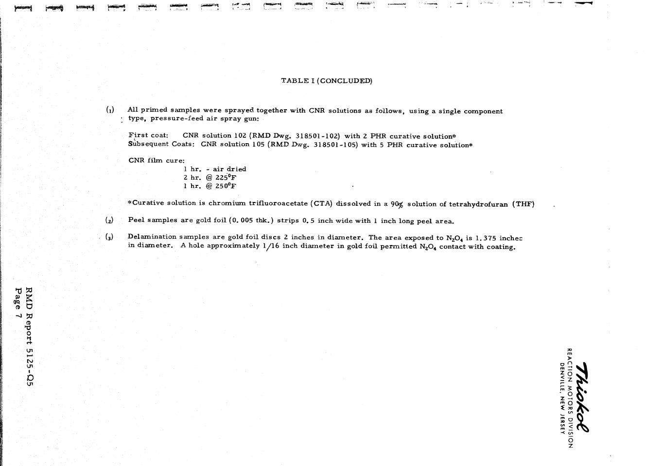
TABLE I (CONCLUDED)
All primed samples were sprayed together with CNR solutions as follows, using a single component type, pressure-feed air spray gun:
F i r s t coat: CNR solution 102 (RMD Dwg. 318501 -102) with 2 PHR curative solution* dbsequent Coats: CNR solution 105 (RMD Dwg. 318501 -1 05) with 5 PHR curative solution*
CNR film cure: 1 hr. - air dried 2 hr. @ 2 2 5 ' ~ 1 hr. @ 2 5 0 ' ~
'Curative solution is chromium trifluoroacetate (CTA) dissolved in a 9% solution of tetrahydrofuran (THF)
(2) Peel samples are gold foil (0. 005 thk.) strips 0.5 inch wide with 1 inch long peel area.
. Delamination samples are gold foil discs 2 inches in diameter. The area exposed to N204 is 1.375 inche; in diameter. A hole approximately 1/16 inch diameter in gold foil permitted N204 contact with coating.
REACTION MOTORS DIVISION DENVILLE, NEW JERSEY
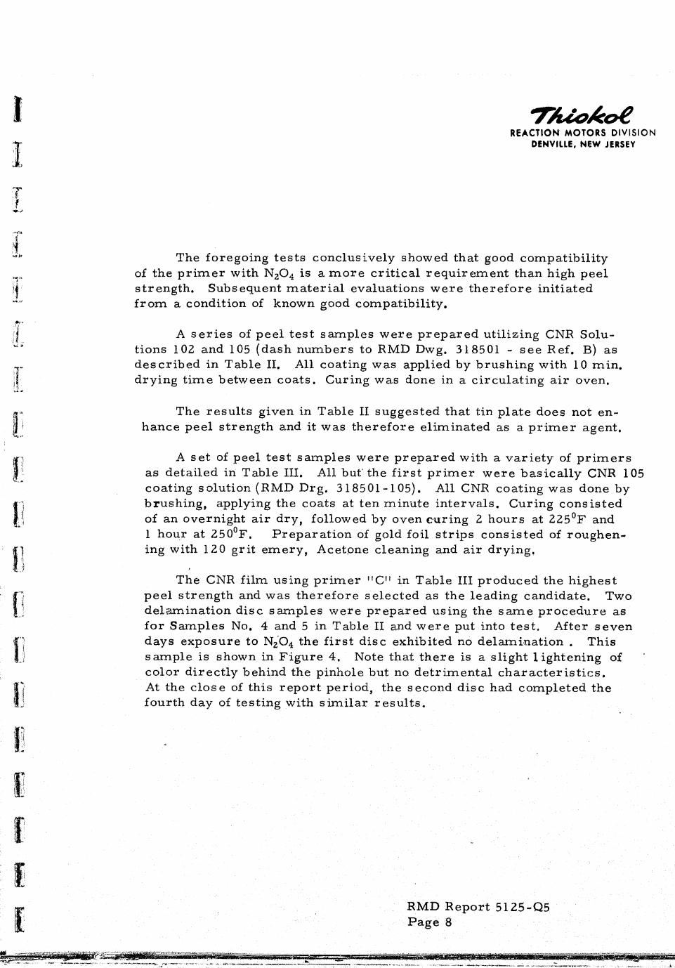
The foregoing tests conclusively showed that good compatibility of the p r imer with NZ04 is a m o r e cr i t ical requirement than high peel strength. Subsequent mater ia l evaluations were therefore initiated f rom a condition of known good compatibility.
A s e r i e s of peel test samples were prepared utilizing CNR Solu- tions 102 and 105 (dash numbers to RMD Dwg. 318501 - see Ref. B) as described in Table 11. A l l coating was applied by brushing with 10 min. drying t ime between coats. Curing was done in a circulating a i r oven.
The results given in Table I1 suggested that tin plate does not en- hance peel strength and it was therefore eliminated as a p r imer agent.
A s e t of peel tes t samples were prepared with a variety of p r imer s as detailed in Table 111. A l l but' the f i r s t p r imer were basically CNR 105 coating solution(RMD Drg. 318501-105). A l l CNR coating was done by brushing, applying the coats at ten minute intervals. Curing consisted of an overnight a i r dry, fo1l.o~ ed by oven curing 2 hours at 2 2 5 ' ~ and 1 hour at 2 5 0 ' ~ . Preparation of gold foil s t r ips consisted of roughen- ing with 120 grit emery, Acetone cleaning and a i r drying.
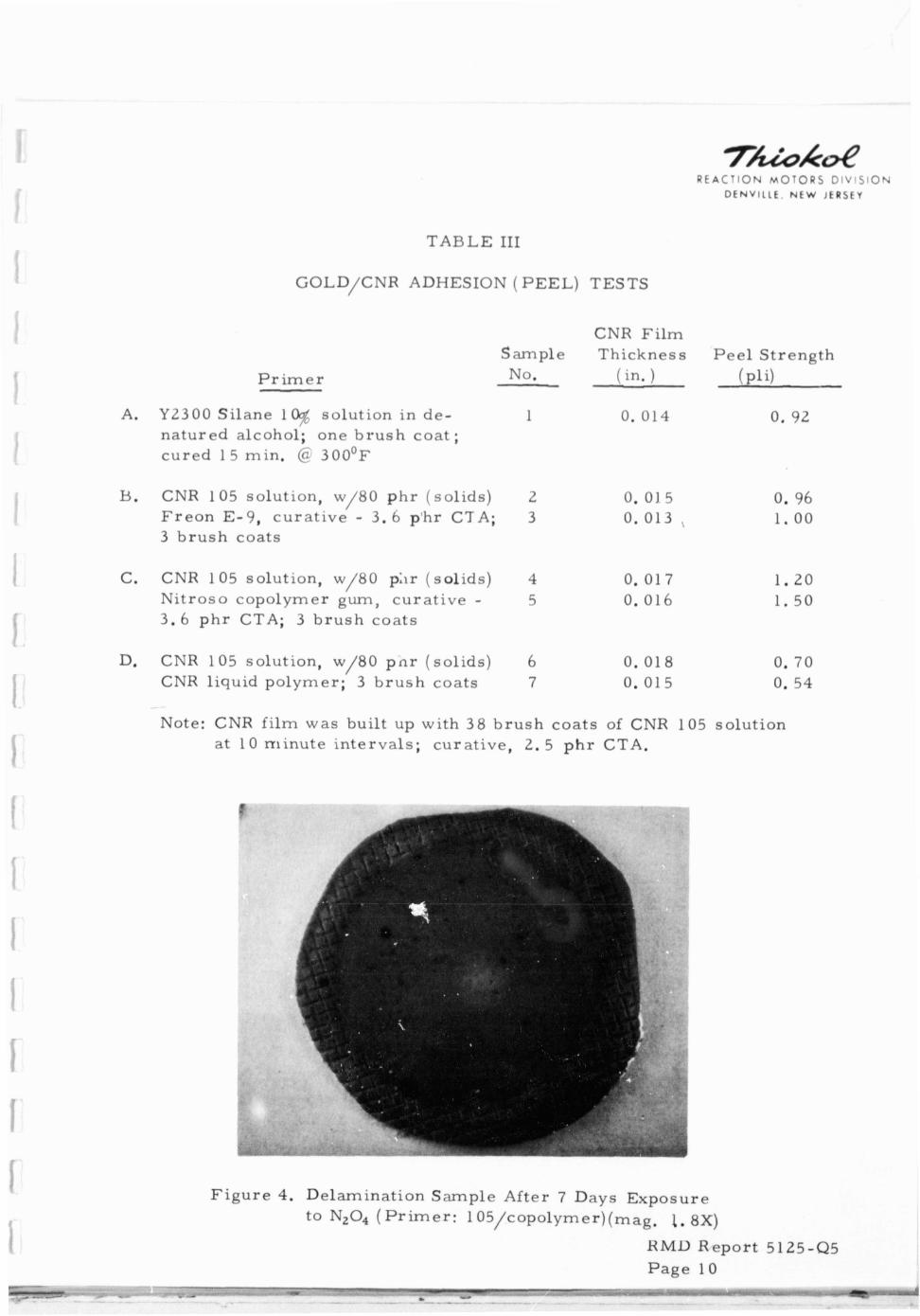
The CNR film using pr imer l1Cl1 in Table I11 produced the highest peel strength and was therefore selected as the leading candidate. Two delamination disc samples were prepared using the s ame procedure as fo r Samples No. 4 and 5 in Table I1 and were put into test . After seven days exposure to Nz'04 the f i r s t disc exhibited no delamination . This sample is shown in Figure 4. Note that there is a slight lightening of color directly behind the pinhole but no detrimental character is t ics . At the close of this report period, the second disc had completed the fourth day of testing with s imilar results.
RMD Report 51 25-Q5 Page 8
R E A C T I O N MOTORS D I V I S I O N D E N V I L L E , N E W !CRSEY
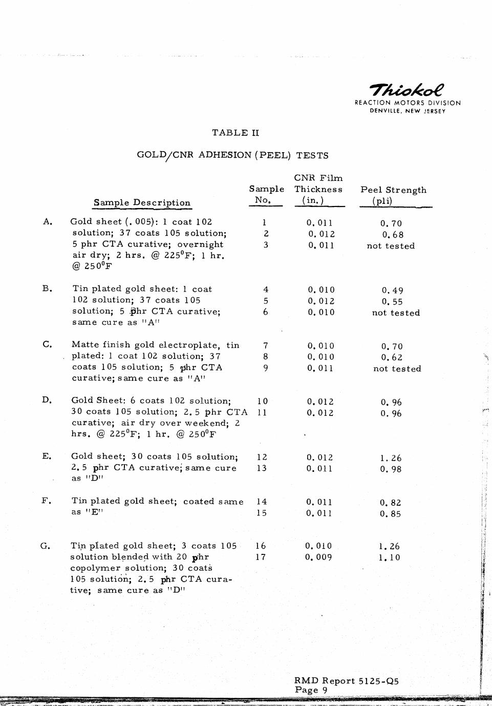
TABLE I1
GOLD/CNR ADHESION (PEEL) TESTS
CNH Fi lm Sample Thickness P e e l Strength
Sample Description -- No. (in. ) ( ~ l i )
Gold shee t (. 005): 1 coat 102 1 0.01 1 0. 70 solution; 3 7 coats 105 solution; 2 0. 012 0. 68 5 phr CTA curative; overnight 3 0. 01 1 not tes ted a i r dry; 2 h r s . @ 2 2 5 ' ~ ; 1 hr. @ 2 5 0 ~ ~
Tin plated gold sheet: 1 coat 4 102 solution; 3 7 coats 105 5 solution; 5 .phr CTA curative; 6 same cure as I1Af1
Matte finish gold electroplate, t in 7 plated: 1 coat 102 solution; 3 7 8 coats 105 solution; 5 phr CTA 9 curative; s a m e c u r e as l t A 1 l
0.010 0.49 0.012 0. 55 0.010 not tes ted
0.010 0. 70 0. 010 0.62 \ 0.011 not tes ted
D. Gold Sheet: 6 coats 102 solution; , 10 0.012 0. 94 30 coats 105 solution; 2. 5 p h r CTA 11 0.012 0. 96 curative; air d r y over weekend; 2
I hrs . @ 2 2 5 ' ~ ; 1 h r . @ 2 5 0 ' ~
E. Goldshee t ; 3 0 c o a t s 105solut ion; 12 0. 012 1. 26 2.5 phr CTA curative; s a m e c u r e 13 0.01 1 0. 98 as "D"
F. Tin plated gold sheet; coated s a m e 14 as "EM 15
G. Ti,n plated gold sheet ; 3 coats 105 16 0.010 1. 26 I I ; i
solution blended with 20 p h r 17 0.009 1.10 i copolymer solution; 3 O coats IX 105 solution; 2. 5 phr CTA cura- I!
! ' , $
tive; s a m e c u r e as I'DH tj i
R E A C 7 l O h ( MOTORS C)!v lSION
DENVILLE, NEW J E R S E Y
TABLE I11
GOLD/CNR ADHESION ( PEEL) TESTS
P r i m e r
CNR F i l m Sarnple Th ickness P e e l S t reng th No. ( in. ) (p l i )
A. Y2300 S i lane 1 solut ion in de- 1 0. 014 0. 92 na tu r ed alcohol'; one b r u s h coa t ; c u r e d 15 min. @ 3 0 0 ' ~
. C N R 1 0 5 s o l u t i o n , w / 8 0 p h r ( s o l i d s ) 2 0.01 5 0. 96 F r e o n E-9 , c u r a t i v e - 3.6 p'hr CTA; 3 0. 013 , 1 .00 3 b r u s h coats
C. CNR 105 solut ion, w/80 phr ( so l i d s ) 4 0. 01 7 1 .20 N i t ro so copo lymer gum, c u r a t i v e - 5 0. 016 1. 50 3 .6 p h r CTA; 3 b r u s h coa t s
D. CNR 105 solut ion, w/80 p n r ( so l i d s ) 6 0. 018 CNR l iquid po lymer ; 3 b r u s h coats 7 0. 015
Note: CNR f i l m was built up with 38 b r u s h coa t s of CNR 105 solu t ion a t 10 m i n u t e i n t e rva l s ; cu ra t ive , 2. 5 p h r CTA.
F i g u r e 4. Delaminat ion Sample After 7 Days Exposure to N,O, ( p r i m e r : 105/copolymer)(mag. 1*8X)
R M U R e p o r t 5125-Q5 P a g e 10
Lh --
, -- -- - *Ilr -.. I . -. - -
REACTION MOTORS DIVISION DENVILLE, NEW J E R S E Y
Because it remains uncured, the Nitroso copolymer serves as a tacki- f i e r and is capable of being m o r e readily deformed and elongated than cured CNR. It was postulated that this type of mater ia l would bond to both gold and CNR and se rve as a link between the two interfaces.
To evaluate the effect of varying the amount of copolymer used, a s e t of peel t e s t samples were prepared with copolymer varied. f rom 40 to 100 phr. Details and peel strengths a r e given in Table IV. It is of interest that all samples except No. 1 and No. 2 peeled in an intermittent fashion, cycling between cohesive and adhesive failure. Cohesive failure occurred at the interface between p r imer coats and straight CNR, The optimum quantity of copolymer appears to be 80 phr.
TABLE IV
GOLD/CNR ADHESION (PEEL) TESTS
Pr imer Sample Thickness Peel Strength
No. (in. ) (PI i) - A. CNR 1 05 solution, w/40 phr 1 0. 014 1.45
2 ,,P"" (solids) Nittoso copolymer gum; 0.016 1.53 3.6 Phr CTA curative; 6 brush
, coats
B. S a m e as " A f 1 except w 80 phr co- polymer
/
C. Same as " A f f except w/100 phr 5 copolymer 6
D. CNR 102 solution, w/80 phs co- 7
polymer; 3.6 phr CTA curative; 8 6 brush coats
Note: CNR fi lm was built up with 36 coats of CNR 105 solution; 2. 5 p,hrCTA curative; overnight a i r dry; oven cure 2 hrs . @ 2 2 5 ' ~ ; 1 hr. @ 2 5 0 ' ~
RMD Report 6125-Q5 Page 11
REACTION MOTORS D I V I ,ION DENVILLE, NEW J E R S E Y
2. Candidate Chosen
The adhesive sys tem selected to be used f o r fabricating the f i r s t s i x inch bladder will therefore b e the CNR 105 solution with n i t roso copolymer gum added. A s u m m a r y of the formula.tions of p r i m e r and coatings is given in Table V.
TABLE V
PRIMER AND COATING SOLUTIONS FOR 6" BLADDER A
Ingredients P h r
P r i m e r : CNR Coating Solution 105 (RMD Dwg. 3 18501 - 105) ( 6 coats)
CNR 8 .34 pbw 100 Hi Sil 233 1.66 pbw TriSolvent Blend 90.00 pbw
Nitroso Copolymer Gum Solution Nitroso Copolymer Gum 10. 00 pbw TriSolvent Blend 90.00 pbw
Chromium Trifluoroacetate (CTA) Solution CTA 10.00 pbw
, Tetrahydrofuran (TWF) 90.00 pbw
Coating: CNR Coating Solution 105 ( s e e above) ,
CTA Solution ( s e e above) CTA
B. Mandrel Dissolving Solution Development
This e f for t was completed as reported in RMD Report 5125-Q4, The caust ic solution selected is Oakite No. 130 at a concentration of 0. 5 lb/gallon of water .
I * 1 1
r n RMD Report 5125-Q5 fl ! ' i: i Page 12 -.
REACTION MOTORS DIVISION DENVILLE, NEW JERSEY
C. CNR Coating Technique Evaluation
An attempt was made to develop spray coating technique for CNR solutions by practicing with neoplpene as an inexpensive sirnulant. Severe cobwebbing was experienced and could not be overcome readily. It was concluded that neoprene had spraying character is t ics too adverse to be considered as a practicable p rac- tice medium. Fabricating neoprene bladders was therefore dropped f r o m the program.
The initial s e t of test samples, discussed in Section 111. A. 1 were made by spraying CNR solutions. A pressure-feed gun was used to spray the premixed (coating solution and curative) solution. The quantity to be sprayed did not warrant the added complication of the two- component spray gun. Results were un- satisfactory: Cobwebbing was a ser ious problem; film buildup was very difficult to control and lumps could not be avoided; solvent entrapment was a problem with the resul t that the cured film had a spongy texture.
Vendors of a i r less spray equipment were consulted to evaluate whether their equipment would eliminate any of the above problems. The conclusions were that a i r l ess spraying would be worth considering for production quantity work. Actual demonstration would be required pr ior to assessing the improvement over a i r spraying. Since this was not economically feasible on this program, a i r l ess spraying was dropped from consideration.
Brush coating of CNR solution has been used by RMD for some t ime on a variety of conformal coating applications. It was also used briefly on a bladder program for USAF ( s e e Reference C). Although the ie a r e disadvantages to brush coating, the obvious advantages listed below make' i t an attractive method for this program:
- Film thickness control - Less mater ia l waste - Ease in accomodating changing solution viscosity - Convenient to provide drying time between layers
RMD Report 5125-Q5 Page 13
REACTION MOTORS DIVISION DENVILLE, NEW JERSEY
This method was therefore selected as the coating technique to be used for bladder fabrication.
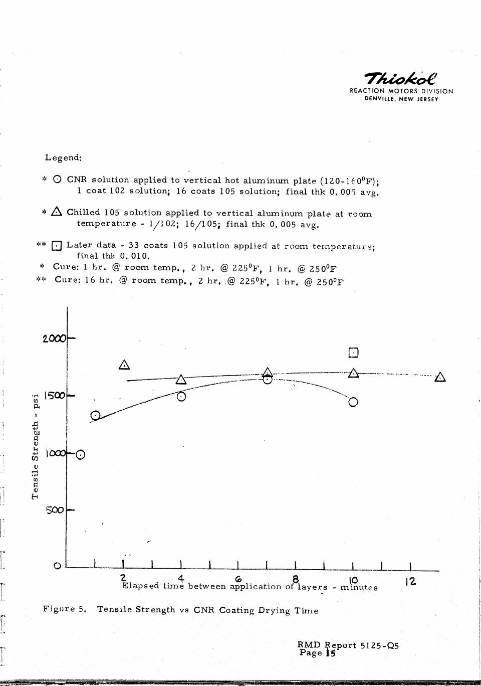
To evaluate the optimum drying t ime between coats of CNR solution, a test was conducted where coating solution was applied to a hot aluminum plate and to a room temperature plate with the elapsed t ime between applications varied from 0.5 minutes to 13 minutes. The resulting films were cured, visu- ally examined under 30X magnification for evidence of bubbles and tensile tested. A l l hot plate samples contained entrained bubbles. A l l room temperature samples were of superior quality, with no evidence of entrained solvent bubbles for 4 minutes (and up) elapsed t ime between coats. The tensile tes t resul ts a r e summarized on Figure 5. They too show the advantage of applying CNR solu- tion to a room temperature mandrel. Subsequently, all coating work will be a i r dried approximately 10 minutes between layers .
D. Fabrication and Tooling
Development of mandrel goldplating technique was performed at NASA/ MSFC during this period. Some difficulty was experienced in plating the s ix inch diameter mandrel s o a back-up unit was prepared and shipped by RMD to MSFC. The four RCS s ize mandrels were polished and shipped to MSFC for plat- ing. The surface finish on these units ranged from 16 to 125 r m s (estimated). Also, there were localized surface irregul.arities and some shallow dents. All were carefully examined pr ior to delivery and assessed to be acceptable condi- tions for the application; i. e . , they would not preclude the achievement of a continuous, leak-free layer of electro-deposited gold.
*
The f i r s t plated s ix inch mandrel was received at RMD near the end of the period. It was inspected visually and by X-ray and appeared suitable for use in fabricating the fir s t bladder:
IV. PROGRAM STATUS
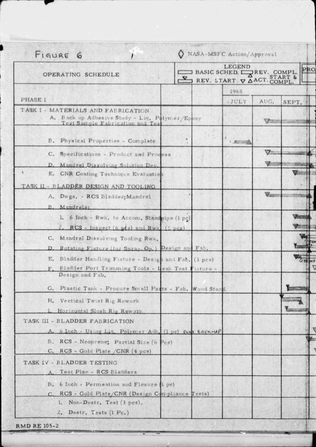
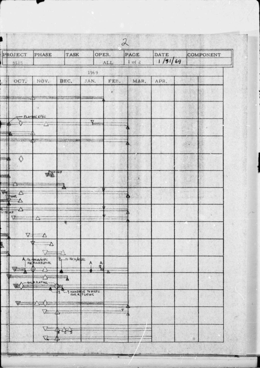
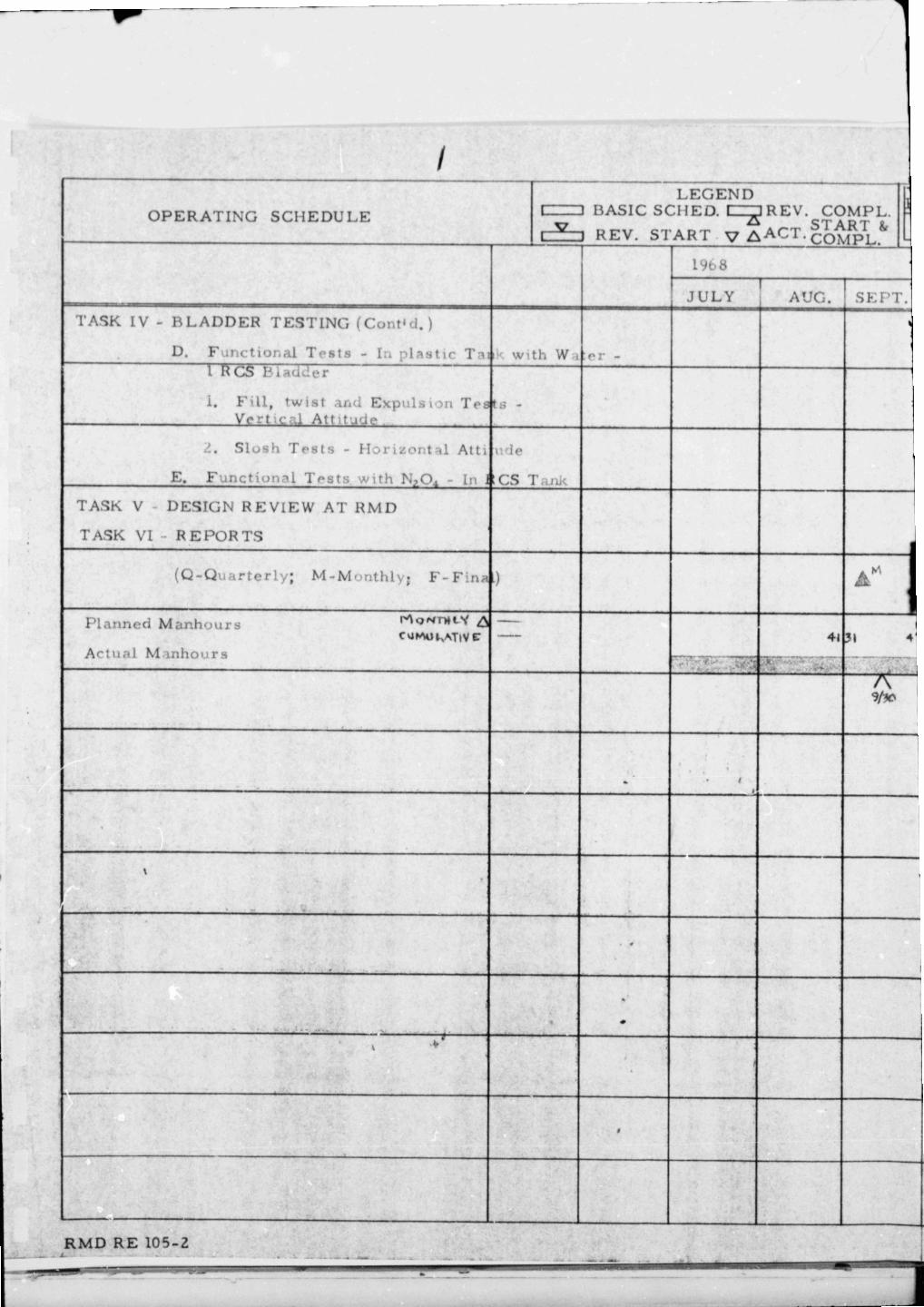
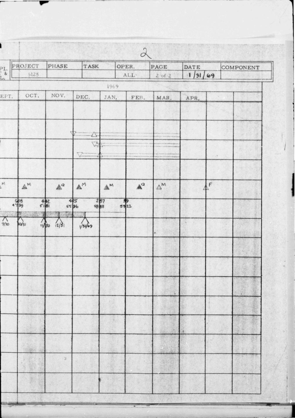
The operating schedule, Figure 6, atta.ched to the back of this report , has - been updated to i l lustrate program status in t e rms of technical accomplishments and also rnanhours expended as of January 31, 1969. The program schedule will require an extension in t ime to permit bladder fabrication and testing following receipt of the plated mandrels.
V. AN'I'ICIPA TED WOKK
Fabricate and tes t the, f i r s t s ix inch bladder.
Prepare bladder tes t plans.
Design handling fixture for R CS bladder.
RMD Report 51 25-Q5 Page 14
REACTION MOTORS DIVISION DENVILLE, N E W J E R S E Y
Legend: . -
* 0 CNR solution applied to ver t ica l hot aluminum plate ( 1 20- 1 Fo'F); 1 coat 102 solution; 16 coats 105 solution; final thk 0. 005 avg.
*c A Chilled 105 solution applied to ver t ical al~a-ninurn plate at room, t empera tu re - 1/102; 16 /105; f inal thk 0. 005 avg.
r I I ** Later data - 3 3 coats 105 solu.tion applied at room ternpera tu~,c ;
final thlr, 0. 01 0.
I * Cure: 1 hr . @ room temp., 2 hr. @ 2 2 5 ' ~ , 1 hr. @ 2 ! j 0 ' ~ ** Cure: 16 hr. @ room temp., 2 hr. ,@ 225O~, 1 hr . @ 2 5 0 ~ ~
0 . ~ 1 I I I - 2
1- 4 6 8 1.0
~ l a ~ s e d t ime between application of l aye r s - minutes 12
Figure 5 . Tensile Strength vs CNX Coating Drying Time
C. HMD Report 5125-Q5 Page A S I j
i .I&- !
REACTION MOTORS DIVISION DENVILLE, N E W J E R S E Y
VI. REFERENCES
Reference A - Letter Defense Contract Administration Services District , Newark, N. 5. , Attention Mr. W, Calabrese f rom Thiokol- RhfD dated 7/15/68 (NASA/MSFC 6401A).
Reference R - ~ h i o k o i - ~ ~ ~ Drawing 318501 I1Coating Solutions. I '
Reference C - Technical Report AF>,/IL-TR -68- 158 prepared by Thiokol- RMD under USAF Contract No. AF33(615)-5311, Project 7381. "Nitroso Rubber Expulsion Bladders for Nitrogen Tatr oxide Application''
"1
; -..- RMD Report 5125-Q5
Page 16 1" i
f i
-- LEGEND
PERATJNP C P T Y X - ~ T T T v L- nASIC SCHED. I= REV. COMPL.
-- LEGEND
PERATJNG SCT-IEDULE 0 nASlC SCI-lED. 1 3 REV. coii/@ START It - - V bACT. COMPL. - - -- -I
4
.TEC7' PHASE 1 TASK OPE! DATE -- 1
I .A ' i7? ---
MAR -
---- LEGEND
E R A T I N G 3DC'LE STAR?' R
~-7 REV. S T A R T v A A ~ T . CObfpL.
I-; I - - - - - -
R M D RE
DAT F: i I C O M I - - , P C - PONE