project report emf detector -...
TRANSCRIPT

1
Project Report
EMF DETECTOR
Adarsh Kumar (120260013)
Yashwanth Sandupatla (120260022)
Vishesh Arya (120260001)
Indian Institute of Technology
Bombay

2
Abstract
Deflection instruments like voltmeters and ammeters, such as moving coil, the magnetic vane, electrodynamometer, hot wire and electrostatic instruments cannot be read with a high accuracy due to some disturbing influences. One such example is stray EMF in the vicinity of our experimental setup. We’ve made an EMF detector which can detect stray EMF and we can choose suitable location for our experiment accordingly.

3
Acknowledgement
The efforts we’ve made in this project would not have been possible without the kind support and help of many individuals. We would like to extend our sincere thanks to all of them. We are highly indebted to Mr. Nitin Pawar and Prof. Pradeep Sarin for their guidance and constant supervision as well as for providing necessary information regarding the project and also for their support in completing the project. We would like to express our gratitude towards our parents and friends for their kind co-operation, encouragement and giving us such attention and time which helped us in completion of this project.

4
Contents
1. Introduction and operation Page 5
2. Algorithm Page 6
3. Arduino Code Page 7-15
4. Circuit Diagram Page 16
5. Snapshots—EMF Detector Page 17
6. Problems Faced Page 18
7. Scope Page 19

5
INTRODUCTION
Our purpose is to build an EMF detector which can detect stray EMF in our
vicinity so that we can apply that knowledge to carefully choose the
environment for experimental setups concerned with accuracy of deflection
instruments. We’ve used LEDs/7-segment LED display, resistors, solid core wire
(antennae) and Arduino.
Operation of the detector:
Changes in electric fields induce a potential in the antenna wire, which is then
read by the Arduino. A code is written which makes LEDs glow whenever
Arduino gets any reading of stray EMF in the vicinity. The function the 3.3 meg-
ohm resistor is changing the sensitivity of the device. In our charge detector, the
antenna picks up a charge from a nearby object and the 3.3 meg-ohm resistor
controls how quickly the charge will dissipate to ground, and therefore how
sensitive the circuit is to external E-fields.

6
ALGORITHM
Important Variables:
1. Sense limit - Variable to control Sensitivity
2. NUMREADINGS - Variable to increase data smoothing
3. val - stores the analog input
4. readings[NUMREADINGS] - Array to store readings for smoothing
Steps:
1. First all the elements are initialized to 0 in the readings array. 2. Then analog input from probe pin 5 is is stored in val. 3. val is the constrained within the sense limit and then mapped to 1-1023 4. All the readings in the loop till the 15th loop is stored in the variable
Total using the readings array.After the 15th loop the Total variable is cleared of the previous readings.
5. The value Total is averaged over the 15 loops and stored in the variable average.
6. The higher the average more number of LED’s will glow.

7
ARDUINO CODE
//EMF Detector
//Project by
//Vishesh Arya - 120260001
//Yashwanth Sandupatla - 120260022
//Adarsh Kumar - 120260013
#define NUMREADINGS 15 // Variable to increase data smoothing
int senseLimit = 15; // Variable to decrease sensitivity (up to 1023 max)
int probePin = 5; // analog 5
int val = 0; // reading from probePin
int LED1 = 2; // connections
int LED2 = 3; // to the 10 LEDs
int LED3 = 4;
int LED4 = 5;
int LED5 = 6;
int LED6 = 7;
int LED7 = 8;
int LED8 = 9;
int LED9 = 10;
int LED10 = 11;
// variables for smoothing

8
int readings[NUMREADINGS]; // the readings from the analog input
int index = 0; // the index of the current reading
int total = 0; // the running total
int average = 0; // final average of the probe reading
//Variable to affect the speed of the updates for numbers. Lower the number the faster it updates.
int updateTime = 40;
void setup() {
pinMode(2, OUTPUT); // specify Display outputs
pinMode(3, OUTPUT);
pinMode(4, OUTPUT);
pinMode(5, OUTPUT);
pinMode(6, OUTPUT);
pinMode(7, OUTPUT);
pinMode(8, OUTPUT);
pinMode(9, OUTPUT);
pinMode(10, OUTPUT);
pinMode(11, OUTPUT);
Serial.begin(9600); // initiate serial connection for debugging/etc
for (int i = 0; i < NUMREADINGS; i++)
readings[i] = 0; // initialize all the readings to 0
intro(); //Runs the intro
}
void loop() {

9
LEDlow();
val = analogRead(probePin); // take a reading from the probe
if(val >= 1){ // if the reading isn't zero, proceed
val = constrain(val, 1, senseLimit); // turn any reading higher than the senseLimit value into the senseLimit value
val = map(val, 1, senseLimit, 1, 1023); // remap the constrained value within a 1 to 1023 range
total -= readings[index]; // subtract the last reading
readings[index] = val; // read from the sensor
total += readings[index]; // add the reading to the total
index = index + 1; // advance to the next index
if (index >= NUMREADINGS) // if we're at the end of the array...
index = 0; // ...wrap around to the beginning
average = total / NUMREADINGS; // calculate the average
if (average > 50){ // if the average is over 50
showLED0(); // Show a 0
}
if (average > 150){ // and so on ...
showLED1(); // Show a 1
}
if (average > 250){
showLED2(); // Show a 2
}

10
if (average > 350){
showLED3(); // Show a 3
}
if (average > 450){
showLED4(); // Show a 4
}
if (average > 550){
showLED5(); // Show a 5
}
if (average > 650){
showLED6(); // Show a 6
}
if (average > 750){
showLED7(); // Show a 7
}
if (average > 850){
showLED8(); // Show a 8
}
if (average > 950){
showLED9(); // Show a 9
}
Serial.println(average); // use output to aid in calibrating

11
delay(updateTime);
}
}
//Show the number 0
void showLED0(){
LEDlow();
digitalWrite(LED1, HIGH);
}
//Show the number 1
void showLED1(){
LEDlow();
digitalWrite(LED1, HIGH);
digitalWrite(LED2, HIGH);
}
//Show the number 2
void showLED2(){
LEDlow();
digitalWrite(LED1, HIGH);
digitalWrite(LED2, HIGH);
digitalWrite(LED3, HIGH);
}
//Show the number 3
void showLED3(){
LEDlow();
digitalWrite(LED1, HIGH);
digitalWrite(LED2, HIGH);
digitalWrite(LED3, HIGH);
digitalWrite(LED4, HIGH);
}
//Show the number 4
void showLED4(){

12
LEDlow();
digitalWrite(LED1, HIGH);
digitalWrite(LED2, HIGH);
digitalWrite(LED3, HIGH);
digitalWrite(LED4, HIGH);
digitalWrite(LED5, HIGH);
}
//Show the number 5
void showLED5(){
LEDlow();
digitalWrite(LED1, HIGH);
digitalWrite(LED2, HIGH);
digitalWrite(LED3, HIGH);
digitalWrite(LED4, HIGH);
digitalWrite(LED5, HIGH);
digitalWrite(LED6, HIGH);
}
//Show the number 6
void showLED6(){
LEDlow();
digitalWrite(LED1, HIGH);
digitalWrite(LED2, HIGH);
digitalWrite(LED3, HIGH);
digitalWrite(LED4, HIGH);
digitalWrite(LED5, HIGH);
digitalWrite(LED6, HIGH);
digitalWrite(LED7, HIGH);
}
//Show the number 7
void showLED7(){

13
LEDlow();
digitalWrite(LED1, HIGH);
digitalWrite(LED2, HIGH);
digitalWrite(LED3, HIGH);
digitalWrite(LED4, HIGH);
digitalWrite(LED5, HIGH);
digitalWrite(LED6, HIGH);
digitalWrite(LED7, HIGH);
digitalWrite(LED8, HIGH);
}
//Show the number 8
void showLED8(){
LEDlow();
digitalWrite(LED1, HIGH);
digitalWrite(LED2, HIGH);
digitalWrite(LED3, HIGH);
digitalWrite(LED4, HIGH);
digitalWrite(LED5, HIGH);
digitalWrite(LED6, HIGH);
digitalWrite(LED7, HIGH);
digitalWrite(LED8, HIGH);
digitalWrite(LED9, HIGH);
}
//Show the number 9
void showLED9(){
LEDlow();
digitalWrite(LED1, HIGH);
digitalWrite(LED2, HIGH);
digitalWrite(LED3, HIGH);
digitalWrite(LED4, HIGH);
14
digitalWrite(LED5, HIGH);
digitalWrite(LED6, HIGH);
digitalWrite(LED7, HIGH);
digitalWrite(LED8, HIGH);
digitalWrite(LED9, HIGH);
digitalWrite(LED10, HIGH);
}
//Resets the display
void LEDlow(){
digitalWrite(LED1, LOW);
digitalWrite(LED2, LOW);
digitalWrite(LED3, LOW);
digitalWrite(LED4, LOW);
digitalWrite(LED5, LOW);
digitalWrite(LED6, LOW);
digitalWrite(LED7, LOW);
}
void intro(){
showLED0();
delay(300);
showLED1();
delay(300);
showLED2();
delay(300);
showLED3();
delay(300);
showLED4();
delay(300);
showLED5();
delay(300);
showLED6();

15
delay(300);
showLED7();
delay(300);
showLED8();
delay(300);
showLED9();
delay(300);
LEDlow();
}
16
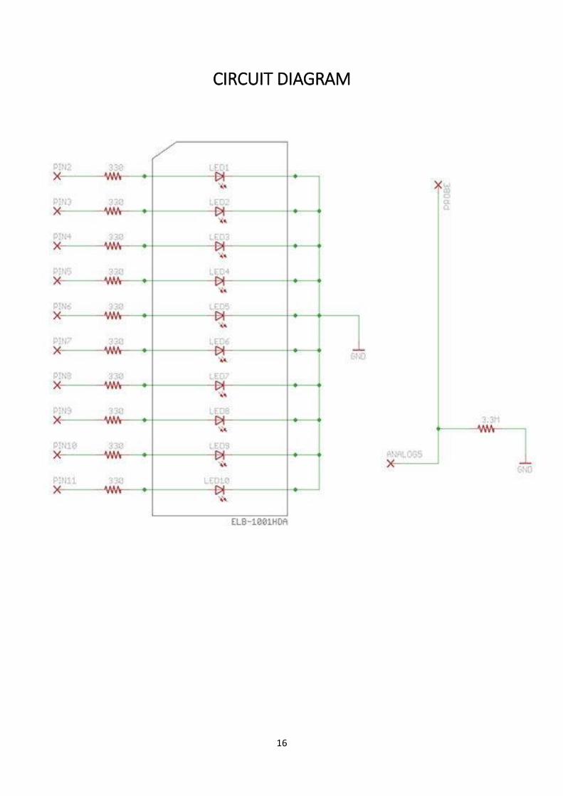
CIRCUIT DIAGRAM

17
EMF DETECTOR-FINALLY!!!!

18
PROBLEMS FACED
One of the major problems, we faced while making this detector was what
should we use as our antennae.
Another problem was, stray EMF keeps fluctuating rapidly and is very difficult to
observe its nature (i.e high or low). So, to tackle this problem, we used a variable
(average) to average some finite number (here 15) of EMF readings in a loop.

19
SCOPE
In the future, we’ll learn how to improve our antennae using a tuning circuit to
detect the presence of stray EMF within a broader range.